cerenkov counter technique in high-energy physics introduction ... developments in the cerenkov...
TRANSCRIPT
Copyright 1973. ~Ill rights reserved
CERENKOV COUNTER TECHNIQUEHIGH-ENERGY PHYSICS
~: 5533
IN
J. Litt and R. Meunier1
CERN, Geneva, Switzerland
CONTENTS1 INTRODUCTION ................................................................ 12 GENERAL PROBLEMS ASSOCIATED WITH THE DETECTION OF CERENKOV RADIATION.. 32.1 The Small Light Yield ................................................................... 32.2 Quantum Efficiency and Noise ........................................................... 32.3 Choice of Cerenkov Angle and Radiator ................................................ 52.4 Attainment of Prescribed Refractive Index .............................................. 82.5 Optical Dispersion in the Radiator ...................................................... 82.6 Optical Aberrations ...................................................................... 92.7 Energy Loss, Scattering, and Diffraction Effects ....................................... 112.8 Phase Space Acceptance ................................................................. 123 THRESHOLD CERENKOV COUNTER ..................................................... 144 DIFFERENTIAL CERENKOV COUNTER ................................................... 194.1 Differential Counter using a Solid or Liquid Radiator .................................. 194.2 Differential Gas Counter ........................................ ’ ......................... 234.3 Optically Corrected Gas Differential Counter .......................................... 255 COMPARISON OF THRESHOLD AND DIFFERENTIAL CERENKOV COUNTERS ............. 296 PATTERN RECOGNITION IN A FOCUSING CERENKOV COUNTER ........................ 346.1 Ring Image Detector ..................................................................... 346.2 Spot Image Detector ..................................................................... 376.3 Multiplexed Cerenkov Counter .......................................................... 397 CONCLUSIONS ................................................................. 40
1 INTRODUCTION
Following the discovery of Cerenkov radiation in 1934 by Vavilov (1) and Cerenkov(1) and the subsequent theoretical explanation by Tamm & Frank (2) in 1937, great deal of effort has been put into the investigation of the properties of thisphenomenon and its application. Several review articles have appeared (3) thatcover the whole subject of Cerenkov radiation in great detail. The aim of the presentarticle is to supplement the previous reviews by placing emphasis on the recentdevelopments in the Cerenkov counter technique as applied to the physics researchat high-energy accelerators. The applications to cosmic ray research and to themeasurement of total deposited energy, such as in shower detectors, will not bereviewed (3).
1 Visitor from CEN, Saclay, France.
www.annualreviews.org/aronlineAnnual Reviews
Ann
u. R
ev. N
ucl.
Sci.
1973
.23:
1-44
. Dow
nloa
ded
from
arj
ourn
als.
annu
alre
view
s.or
gby
HA
RV
AR
D C
OL
LE
GE
on
02/2
8/05
. For
per
sona
l use
onl
y.
2 LITT & MEUNIER
Tamm & Frank (2) developed a classical theory to account for Cerenkov radia-tion based on the idea that a charged particle moving in a transparent mediumwith a uniform velocity larger than the velocity of light in the medium emits aradiation along a conical wavefront. The angle of emission 0 of the radiation of agiven wavelength 2 is related to the relative velocity /3(= v/c) of the particle andthe refractive index n of the medium by the relation
cos 0(2) 1~fin(2) 1.
The theory also produced the spectral distribution and hence the intensity of theradiation. These predictions were confirmed experimentally by Cerenkov (4), andthere followed a quantum-mechanical theory of the effect by Ginsburg (5) in 1940.
Relation 1 can be rewritten as
COS 0(2) = Ulight(,~)/Uparticle 2.
which shows that the angle of emission of the light is directly related to the ratioof the velocity of the light in the radiator to the particle velocity. This fact explainsthe usefulness of Cerenkov radiation in the field of elementary particle physics. Theoptical measurement of the emission angle of the light together with the knowledgeor measurement of the velocity of light in the same medium affords the meansof determining the velocity of a particle and its direction within the accuracy ofoptical techniques.
For a high-energy charged particle, the measurement of its relative velocity /3together with a measurement of its momentum p is practically the only way todetermine the mass m of the particle, which is deduced from the relation
m = P/fiT with 7 = (1 __f12)-~3.
and c = 1
By using the Cerenkov effect, the velocity/3 can be measured to an accuracy in therange of 10-2 to 10-v, with an accuracy in m for a single particle given by
dm/m = ~2(dfl/fl) + (dp/p) 4.
A Cerenkov counter consists of a transparent medium (gaseous, liquid, or solid)in which the radiation is emitted, and an associated electronic detector. The researchat high-energy particle accelerators uses several types of Cerenkov counters whichdiffer in their mechanical arrangements and quality of the optical systems. Fromrelation 1 it is sccn that the radiation is not produced unless fin(2)> 1 (i.e. theCerenkov angle must be greater than zero). The possibility of detecting particleswith velocities above a given value is exploited in the threshold Cerenkov counter.An instrument which detects the radiation over a small range of angle at a nominalvalue 0 is known as a differential Cerenkov counter.
The Cerenkov effect is the result of an electromagnetic interaction that produceslight which can be detected by photomultipliers. Cerenkov detectors, which arestandard equipment in high-energy physics experiments, provide a nondestructivemethod for measuring the mass-of individual charged particles.
www.annualreviews.org/aronlineAnnual Reviews
Ann
u. R
ev. N
ucl.
Sci.
1973
.23:
1-44
. Dow
nloa
ded
from
arj
ourn
als.
annu
alre
view
s.or
gby
HA
RV
AR
D C
OL
LE
GE
on
02/2
8/05
. For
per
sona
l use
onl
y.

CERENKOV COUNTERS IN HIGH-ENERGY PHYSICS 3
2 GENERAL PROBLEMS ASSOCIATED WITH THEDETECTION OF CERENKOV RADIATION
2.1 The Small Liyht Yield
The number of Cerenkov photons Nr emitted per unit length of a radiator oflength L in the Tamm-Frank theory is given by
dN,/dL = 2rco~Z2 [1-(1/f12n2)~(d2/22) 5.2
where ~ is the fine structure constant (~ 1/137), Ze is the charge of the particle, and
21, 22 define the limits of the spectral range of the detected radiation. Relation 5shows that most of the Cerenkov light appears at small values of L
Due to the Z2 dependence in equation 5, a particle with large charge can producesufficient Cerenkov light intensity to be recorded on photographic emulsion (6).However for singly charged particles the light yield is quite small: for example, theenergy loss by Cerenkov radiation in the wavelength bandwidth from 200 to 600 nmis about 1 keV, which is about 100 times less than the energy loss by ionization.It is therefore most important in a Cerenkov detector to minimize the effect ofionization which can cause some radiators to scintillate, and to detect the Cerenkovradiation over as wide a bandwidth as possible.
Thus, many effort~ have been made to improve the light transmission and extendthe sensitivity of the photodetector into the ultraviolet region where the light yieldis greater. At long wavelengths the detection by the counter is limited simultaneouslyby the low-energy threshold of the photocathodes and the reduced Cerenkovphoton emission as given in equation 5. There is not much to be gained in thisregion of the spectrum.
In relation 1 the refractive index n(2) and Cerenkov angle 0(2) are functions of wavelength 2. Extending the wavelength bandwidth leads to a dispersion d0/d), ofthe Cerenkov light that is detrimental to the predsion of the measurement of 0, andhence /~. The dispersion can be made smaller by reducing the bandwidth usingoptical filters. However, this is possible only when the flux of particles can compensatefor the reduced light yield in a given radiator thickness. For single-particle detectionone can either reduce the dispersion by using a smaller value of 0 or apply achromaticcorrection to the optics.
2.2 Quantum Efficiency and Noise
Only the best quality photomultipliers or image intensifiers can be considered foruse in single-particle detectors. The detection efficiency of a given counter is obtainedby folding the quantum efficiency of the photodetector with the optical transmissionand the Cerenkov light spectrum.
As a rule, only the specifications of the photo¢athode efficiency are available fromthe manufacturers. However, the efficiency for collecting the photoelectrons at theanode depends upon the wavelength of the light, especially at the level for detectingsingle photoelectrons (7). High-speed photomultipliers collect the photoelectrons
www.annualreviews.org/aronlineAnnual Reviews
Ann
u. R
ev. N
ucl.
Sci.
1973
.23:
1-44
. Dow
nloa
ded
from
arj
ourn
als.
annu
alre
view
s.or
gby
HA
RV
AR
D C
OL
LE
GE
on
02/2
8/05
. For
per
sona
l use
onl
y.
4 LITT & MEUNIER
focusing them onto a small-size first dynode, which is elaborately calculated tominimize transit time differences. Photoelectrons that are emitted with initiafenergies exceeding a level of about 0.8 eV are likely to miss the first dynode. Thisoccurs for wavelengths shorter than about 450 rim, which is the region of interestfor Cerenkov light detection. This effect depends strongly on the magnitude of theaccelerating field in the region between the photocathode and the first dynode,although raising the collecting field also increases the noise level of the detector.
This reduction of collection efficiency does not continue at wavelengths shorterthan 300 nm because a larger fraction of the photoelectrons is emitted with verylow velocities (see Duteil et al, 8); however in this region the detection of Cerenkovlight is restricted by the transmission through the material of the counter opticsand the entrance window of the photodetector. By using ultraviolet-transmittingmaterials such as fused silica, the detection of the Cerenkov light can be accomplishedout to wavelengths of about 200 rim.
The effective detection efficiency of a photodetector as used in a Cerenkovcounter with the associated electronic equipment can be measured if one defines awavelength bandwidth that would be transmitted by a standard set of optics. It isconvcnient to define the standard optics as those that would be used in the simplestthreshold Cerenkov counter, consisting of(a) onc front-aluminized mirror, 9speciallycoated for reflection at ultraviolet wavelengths and containing a protective-interference layer of ;~/2 thickness of MgFz at 350 nm, and (b) one exit windowof ultraviolet-transmitting fused silica which is antireflection coated with a layer of~/4 thickness of MgFz at 350 rim. These details are not so restrictive, but dointroduce the necessary transmission attenuation that would be present in anythreshold or differential Cerenkov counter. With this standard optics it is possibleto experimentally measure (8) and compare the performances of different types photomultipliers.
For a Cerenkov counter of length L and Cerenkov angle 0, the number ofphotoelectrons N produced by the passage of a singly charged high-energy particleis given by
N = A LOz 6.
where A characterizes the photodetector taking into account the Cerenkov lightspectrum and the transmission of the standard optics. Values of the parameter Ahave been measured in several laboratories (8) and are in good agreement. Thebest photomultiplicrs available today, having a fused silica entrance window and abi-alkali (K-Cs-Sb) photocathode, have a value of the parameter A from about 100-150 cm-~. Photomultipliers having a photocathode of lower quantum efficiencyand a glass entrance window provide a value of A from about 50~0 cm- ~.
In a focusing type of Cerenkov counter the light flash associated with a singleparticle is isochronous for a particle traveling along the counter.axis because thetime taken by the light is equal to the time of flight of the particle. For particlesat a distance from the axis, because the wavefront of the Cerenkov light is conical,the duration of the flash of light is typically a few picoseconds. Hence it is thetransit time-spread in the photomultiplier which is the main contributor to the
www.annualreviews.org/aronlineAnnual Reviews
Ann
u. R
ev. N
ucl.
Sci.
1973
.23:
1-44
. Dow
nloa
ded
from
arj
ourn
als.
annu
alre
view
s.or
gby
HA
RV
AR
D C
OL
LE
GE
on
02/2
8/05
. For
per
sona
l use
onl
y.

CERENKOV COUNTERS IN HIGH-ENERGY PHYSICS 5
coincidence resolving time of the Cerenkov detector; this time can be of the orderof a few nanoseconds.
The noise pulses in a photomultiplier, mainly arising from single photoelectrons,are indistinguishable from true signals since the threshold for the detectionelectronics is generally set below this level. Therefore for the differential type ofCerenkov counter the light output is in most cases shared between several photo-multipliers, and the output signals are placed in a coincidence arrangement. Inthis manner the accidental count rate can be reduced to an extremely low level atthe expense of reducing the overall counting efficiency of the detector.
2.3 Choice of Cerenkov Angle and Radiator
Since the Cerenkov light is emitted at a given angle O, it appears to an observer tocome from a circle positioned at infinity. Focusing optics can be used to concentratethis light onto a ring image of radius r in the focal plane of the system. The radiusr is given by r =ftanO, where f is the focal length of the optics. The basicprinciple of the differential Cerenkov counter is to detect these ring images usingdiaphragm~ placed in front of photodetectors. The counter detects the radiation
I0-6 ~
10" llil i 1 i I I1000 100 10
BEAIvt NtO~NTLltvt (GeV~c)
Figure I Velocity difference between pairs of particles as a function of the beammomentum.
www.annualreviews.org/aronlineAnnual Reviews
Ann
u. R
ev. N
ucl.
Sci.
1973
.23:
1-44
. Dow
nloa
ded
from
arj
ourn
als.
annu
alre
view
s.or
gby
HA
RV
AR
D C
OL
LE
GE
on
02/2
8/05
. For
per
sona
l use
onl
y.
6 L1TT & MEUNIER
emitted at a given angle 0 and within an angular range of A0. The velocity resolutionAfl/fl achieved by such a detector is obtained by differentiating equation 1, and isgiven by
Afl/fl = tan 0(2)A0 7.
In a beam of particles of momentum p, the velocity difference between twoparticles of mass m0 and m1 is given by
(Aft/r) .... = (m~ - m~)/2p 2 8.
The velocity differences between different pairs of particles as a function of the beammomentum are indicated in Figure 1. The velocity resolution of a differential counterat the highest beam momentum is normally designed to be two or three times smallerthan the velocity difference between the particles m0 and ml.
From equation 7 the velocity resolution of a differential counter is proportionalto 0 and, providing that the optics is well designed, can be improved by reducingA0. The light output from the counter, from equation 6, is proportional to 02. Thus,the final choice of angle will be a compromise between a required velocity resolutionand angular acceptance for a given application, and a minimum tolerable amountof light output for a given size and cost of the device.
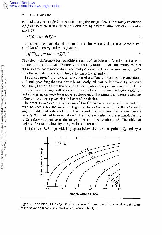
In order to achieve a given value of the Cerenkov angle, a suitable materialmust be chosen for the radiator. Figure 2 shows the variation of the Cerenkovangle for different values of the refractive index n as a function of the particlevelocity r, calculated from equation 1. Transparent materials are available for usein Cerenkov counters over the range of n from 1.0 to about 1.8. The differentregions of n are obtained by using various materials:
1. 1.0 <~ n ~ 1.13 is provided by gases below their critical points (9), and by
0.5
I I I I
0.6 0.7 0.8 0.9 1.0
RELATIVE V~LOCITY J3 (=v/c)
Figure 2 . Variation of the angle 0 of emission of Cerenkov radiation for different valuesof the refractive index n as a function of particle velocity ft.
www.annualreviews.org/aronlineAnnual Reviews
Ann
u. R
ev. N
ucl.
Sci.
1973
.23:
1-44
. Dow
nloa
ded
from
arj
ourn
als.
annu
alre
view
s.or
gby
HA
RV
AR
D C
OL
LE
GE
on
02/2
8/05
. For
per
sona
l use
onl
y.

CERENKOV COUNTERS IN HIGH-ENERGY PHYSICS 7
few liquified gases st~ch as n- 1.11 for liquid hydrogen and n = 1.13 for liquiddeuterium.
2. 1.13 <~ n <~ 1.35 is provided by gases above their critical points.
3. 1.28 ~ n ~ 1.33 i~ provided by fluorocarbons of quite high density that havehigh transparency in the ultraviolet and yet low dispersion.
4. n ~ 1.33 is provided by many liquids including light hydrocarbons and alsowater and glycerine mixtures.
5. n ~ 1.46 is achieved by many solids such as fused silica, plastics, andglasses.
An inhomogeneous medium can be used in a Cerenkov counter, provided that thescale of the inhomogeneity is small compared to the wavelength of the Cerenkovradiation. The use of a mixture of very fine silica powder and air has been
suggested (10) ~hich, by varying the compaction factor, can produce average¯ values of the refractive index in the range from 1.05-1.20~
There are four cases of the application of Cerenkov light to particle velocitydetermination that can be distinguished:
1. Threshold Cerenkov counter using a solid or liquid radiator: The thresholdvelocity flo -- 1In (corresponding to 0 = 0) can be quite low. For example, usingPlexiglas with n = 1.50 produces a threshold value flo >~ 0.67 or Yo >~ 1.3.
2. Threshold gas Cerenkov counter: To obtain high values of n it is oftennecessary to use extremely high pressures. Hence a reasonable upper limit to theavailable range of n could be to use ethylene gas at 50 atm, which produces avalue n = 1.13. This corresponds to a threshold velocity flo >~ 0.88 or ~’0 >~ 2.15.
3. Differential Cerenkov counter using a solid or liquid radiator: Since thistype of counter uses a relatively large value of 0, the velocity resolution cannotbe made extremely small by reducing A0 since the angular acceptance becomestoo small for the counter to be useful. The lowest index liquid which is commonlyused is FC75 which, for Afl/fl ~< 5 × 10 4 and A0 ~ I0- 3 tad, corresponds to a valuen -- 1.28. Thus the upper limit of fl becomes equivalent to particle separation oftypically the doublet ~, K in beams of up to about 5 QeV/c. The lower limit to/3corresponds to the largest n value, which is about 1.58 for styrene or the liquidDC704. Hence this type of counter is approximately restricted to values offl ~ 0.63 or 7 ~> 1.3.
4. Differential gas Cerenkov counter: These counters have an application inbeams up to a few hundred GeV/c, but the lower limit is set by the requirement ofusing a gas at a reasonable pressure, which results in a limit of approximately/3 >~ 0.8 or ~ >~ 1.60.
A gas radiator provides a simple means of changing the refractive index merelyby altering the operating pressure. The change of index is given by the Lorentz-Lorenz law :
(n2 -- 1)/(n 2 +2) = (R/M)p 9.
where R is the molecular refractivity, M is the molecular weight, and p is the gasdensity. For pressures that are not too high, equation 9 can be approximatedto high accuracy by
www.annualreviews.org/aronlineAnnual Reviews
Ann
u. R
ev. N
ucl.
Sci.
1973
.23:
1-44
. Dow
nloa
ded
from
arj
ourn
als.
annu
alre
view
s.or
gby
HA
RV
AR
D C
OL
LE
GE
on
02/2
8/05
. For
per
sona
l use
onl
y.

8 LITT & MEUNIER
(n- 1) = 0- 1) 10.
where no is the refractive index of the gas for a given wavelength of light, at thetemperature of the counter, and at a pressure of 1 atm. The pressure P is inatmospheres.
2.4 Attainment of Prescribed Refractive Index
Sufficient precision is required in the value of the refractive index of the radiatorto achieve a given velocity resolution Aft///. For low-velocity particles there is noproblem with the liquid or solid radiator whose refractive index can be measuredto a few parts in 104 or 105. The only necessary precaution is taking care of anytemperature effects. As the particle velocity increases, so does the requiredprecision of the index measurement. At high energies gases are used as the radiatorand knowledge of the refractive index becomes more difficult. The index dependsupon the gas density, as given in equation 10, which in (urn depends upon thetemperature and pressure according to the equation of state. The refractive indexcan be calculated from a measurement of the gas pressure and temperature, butsuch a procedure can be seriously affected by any impurity in the gas. Othermethods have been used for measuring the refractive index, such as having anoscillating circuit containing a capacitor which is immersed in the gas, althoughsuch methods require a refractometer for absolute calibration.
For accurate work the refractive index should be continuously monitored usingan interferometer, which directly measures the quantity (n-1) by counting thenumber of fringes. In this way temperature, pressure, and purity controls are notnecessary. This method also leads to an absolute determination of the value of flprovided that the Cerenkov angle 0 is known; as occurs in an achromaticcounter.
If one aims at, say, 10 increments of the refractive index setting between thepion and kaon peaks in a mass spectrum for a beam of momentum p, therequired accuracy An/n is given by
An/n ~ ~(fl~- flK)/fl~ ~ (m~- mE~)/20p2 11.
where m~, mr are the masses of the pion and kaon, respectively. Hence for
p = 200 GeV/c An/n = 2.8 × 10⁻⁷p = 300 GeV/c An/n = 1.2 × 10⁻⁷
p = 400 GeV/c An/n = 7.0 × 10- s
With a Rayleigh type of refractometer, an accuracy An/n of better than 10- 7 can beachieved.
2.5 Optical Dispersion in the Radiator
In equation 1 the Cerenkov angle 0 i~ given as a function of the wavelength 2of the light. Hence there is a spread (dispersion) of the Cerenkov angle due to thevariation of the refractive index of the radiator as a function of 2. The amountof chromatic dispersion A0olsp is given by differentiating equation 1.
www.annualreviews.org/aronlineAnnual Reviews
Ann
u. R
ev. N
ucl.
Sci.
1973
.23:
1-44
. Dow
nloa
ded
from
arj
ourn
als.
annu
alre
view
s.or
gby
HA
RV
AR
D C
OL
LE
GE
on
02/2
8/05
. For
per
sona
l use
onl
y.
CERENKOV COUNTERS IN HIGH-ENERGY PHYSICS 9
AOD~sP = An~In(2) tan 0(2)] 12.
where An is the change in refractive index over the range of wavelengths. If onedefines an average wavelength 22 (which is the mean of the distribution of detectedphotoelectrons versus wavelength), and wavelengths 2x, 23, which are the means ofthe distributions on either side of the average wavelength, then equation 12 canbe rewritten as: ,
AOD,sp = [n(22)-- 1]/[n(22)v tan 0(22)] 13.
where
v = [-n(2~)-- 1]/[-n(21)-- n(23)] 14.
The parameter v characterizes the optical dispersion in the radiator and is aquantity having the same definition as the Abbe number for glasses but for thewavelength of interest in Cerenkov detectors. Table 1 contains values of theparameter v and refractive index for some commonly used gas radiators. Thewavelengths chosen are those that are compatible with fused silica optics and S13or $133 photocathode spectral response. These values merely illustrate the variationof these parameters for typical gases. An exhaustive list of the physical quantitiesof radiator materials can be found in the review articles by Jelley (3) andZrelov (3).
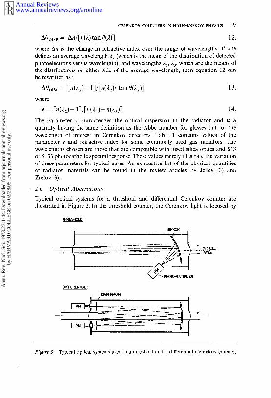
2.6 Optical Aberrations
Typical optical systems for a threshold and differential Cerenkov counter areillustrated in Figure 3. In the threshold counter, the Cerenkov light is focused by
DIFFERENTIAL:
DIAPHRAGM
MIRROR
Fioure 3 Typical optical systems used in a threshold and a differential Cerenkov counter.
www.annualreviews.org/aronlineAnnual Reviews
Ann
u. R
ev. N
ucl.
Sci.
1973
.23:
1-44
. Dow
nloa
ded
from
arj
ourn
als.
annu
alre
view
s.or
gby
HA
RV
AR
D C
OL
LE
GE
on
02/2
8/05
. For
per
sona
l use
onl
y.

10 LITT & MEUNIER
www.annualreviews.org/aronlineAnnual Reviews
Ann
u. R
ev. N
ucl.
Sci.
1973
.23:
1-44
. Dow
nloa
ded
from
arj
ourn
als.
annu
alre
view
s.or
gby
HA
RV
AR
D C
OL
LE
GE
on
02/2
8/05
. For
per
sona
l use
onl
y.

CERENKOV COUNTERS IN HIGH-ENERGY PHYSICS 11
a mirror onto a single photomultiplier. In the case of the differential counter thereflected ring of Cerenkov light is focused onto an adjustable annular diaphragm.The light passing through the aperture of the diaphragm is detected by a numberofphotomultipliers equispaced around the annulus. The simplest way to collect thelight is by using a lens or a spherical mirror; however a spherical mirror ispreferred since it produces less optical aberration.
A spherical mirror of radius of curvature R and focal length f(=R/2) focusesthe cone of light in the differential counter into a ring image of radius r, given by
r =f tan 0 15.
The total radial spread Ar of the ring image is then determined by the sphericaland coma aberrations which, up to third order, are given by :
Ar = - ~(d/f) 3 + ~(d/f)20 16.
The first term in equation 16 is the spherical error and the second term is due tocoma, where d is the useful diameter of the mirror, f is the focal length of themirror, and 0 is the Cerenkov angle. Thus, the angular broadening A00pv of thering image due to the optical aberrations is given by
A0op T = Ar/f 17.
This simple manner of focusing the light is satisfactory in many cases, but to reachthe best performance in velocity resolution and angular acceptance the focusingsystem must be optically corrected. Details of these corrections are given in section 4.
2.7 Energy Loss, Scattering, and Diffraction Effects
As the particle traverses the radiator it loses energy, mainly by the process ofionization, which will alter the value of the velocity fl and hence the value of theCerenkov angle. Multiple Coulomb scattering of the particle causes a broadening ofthe Cerenkov angle.
The ionization loss, which is about 2 MeV × g- 1 × cm- 2 for most materials, canin some applications (11) be corrected by varying the refractive index of theradiator along the length of the counter in such a way as to keep the Cerenkovangle constant. This effect soon becomes negligible as the energy increases.
The angular spread A0ylsc (root mean squared projected angle) due to multiplescattering of the particle of momentum p can be expressed (12)
AOMsc = (E’/pfl)t ~ 18.
where E’ is a constant (~ 15 MeV) and t is the length of the radiator in the unitsof its radiation length. The broadening of the Cerenkov angle has been studied byDedrick (13) for the case of particles undergoing multiple scattering. Within theapproximations of his solution it is concluded that the broadening of the radiationpattern is less than that calculated for the particle trajectory. Thus it is reasonableto use equation 18 as the broadening of the Cerenkov angle.
For a gas radiator of length L, equation 18 can be rewritten as
AOMsc = (E’/p~)[pL(n- 1)/{(n0- 1)X0}] ~ 19.
www.annualreviews.org/aronlineAnnual Reviews
Ann
u. R
ev. N
ucl.
Sci.
1973
.23:
1-44
. Dow
nloa
ded
from
arj
ourn
als.
annu
alre
view
s.or
gby
HA
RV
AR
D C
OL
LE
GE
on
02/2
8/05
. For
per
sona
l use
onl
y.
12 ¯ LITT & MI~UNII~
where p is the gas density, X0 is the radiation length, and the quantities n, n0 ar~defined in equation 10. Values of th~ quantity ~p/{{n0- 1)Xo}~ are ~ncluded inTabl~ l for som~ commonly used gas~s. ~ multipl~ scattering ~rror, as ~wn by~quation 19, is d~t~rmin~d by th~ natur~ of th~ radiator ~d do~s not d~p~ndupon the optical configuration of the counter.
All Cere~ov counters require approximately th~ same thickness of radiator,~xpressed in radiation lengths, for a given photoelectron yield irrespective of th~d~s~ Ccrc~ov angl~. (~s ~s ~n the approximation that ~0 > l, as sho~ inRef. 14.) Sinc~ multipl~ scattering and the magnetic bending of h~-ener~ particlesscale l~ke I/~, they have th~ same relat~v~ e~ect on the smearing of the momentumdetermination of a panicle ~n a ~ven beam-l~ne configuration as th~ momentumincreases.
For th~ d~sign of C~renkov counters that requir~ ~xtr~m~ly high wlocityr~solution light diffraction effects eventually giv~ a limit. ~e broadening of th~Cerenkov cone AOD~FF by diffraction is approximately given by :
AODIFF ~ )~/(L si~ 0) 20.
For example, for a 5-m differential gas Cerenkov counter o~rating at 0 = 25 mradand 2 = 350 nm, the broadening A0~,F~ ~ 3 x 10- 6 tad. If this were the largest con-tribution to the image spread, the effect on the velocity resolution of the counterwould be Afl/fl = tan OAOo,w ~ 8 x 10⁻⁸.
2.8 Phase Space Acceptance
In a focusing counter, for example in d~erential counters and for some thresholdcounters, the Cerenkov li~t is directed onto the photocathode via ~ impingoptics and will be detected only if the light passes through the aperture of adiaphragm. For differential counters the aperture is usually an annular slit sub-tending an angle AOo, and for threshold counters can be defin~ by a single circularaperture placed in front of the photodeteaor.
~e collection of light by the pnotocathode is therefore simultaneously affectedby the value of the angle of emission of the Cerenkov light and the particledivergen~ with respect to the optical ~is of the counter. ~us, all focusingcounters ac~pt only particles that are within a limited region of phase space. ~isreflects the fact that particle identification is achieved throu~ the geometric analysisof the light distribution, uniquely linked to the geometric properties of the particletrajectory.
~e ac~pt~ A~ of a focusing Cerenkov counter can be de~ed as the product-of the Liouville invariant (i.e. the beam emittance) and the momentum acceptan~such that :
A¢ = kS~A~Ap 21.
where Sc is the sensitive area of the photodetector, Ap is the momentum bandwithin which particles coll~ear with the counter axis can be detected, and k is afactor resulting from the integration. The quantity A~ is the solid angle subtendedby the particles of the ~ntral velocity or momentum which are detected such that
www.annualreviews.org/aronlineAnnual Reviews
Ann
u. R
ev. N
ucl.
Sci.
1973
.23:
1-44
. Dow
nloa
ded
from
arj
ourn
als.
annu
alre
view
s.or
gby
HA
RV
AR
D C
OL
LE
GE
on
02/2
8/05
. For
per
sona
l use
onl
y.

CERENKOV COUNTERS IN HIGH-ENERGY PHYSICS 13
00Af~c = (z/4)a0~ 22.
The acceptance Ab of a beam transport system is a constant of motion for aparticle not undergoing acceleration. If there is a Cerenkov counter at some positionin this beam the acceptance can be evaluated at any point along the beam, suchas at the target position where
Ab = St A~t Ap = Ac 23.
In this relation, the subscript t denotes the values at the target position and k is anumerical factor which has been shown (15) to be equal to 1/3.
The acceptance of an identified beam that uses a Cerenkov counter is definedby the requirements for mass separation, which thus fixes the value of A00. Thelargest value of A0o that can be used to detect particles of mass m, whenparticles of mass (m+Arn) are producing light just at the edge of the diaphragm,is given by
(A0o/2) tan 0 = (A/~//~)= (1/72)(Am/m) 24.
and therefore
A0o < (2Am/my2 tan 0) 25.
A more detailed study of matching a differential Cerenkov counter into a beamdesign (15) has shown that
A00 < (2Amf/m~2 tan 0) 26.
where’f is a function limited to values in the range from 0 to 1 depending uponparameters such as target size, collimator size, matrix elements of the beam trans-port system, beam momentum, mass of the particles under consideration, and thequantity tan 0 of the differential Cerenkov counter.
The number of secondary particles Nsec produced in a target by Ninc incidentparticles is given by
Nsec = Ninc(d2N/d~ dp)Af2b p(Am/m)g 27.
where Af~b is the solid angle of the beam and g is an efficiency function with avalue between 0 and 1.
The study of the above functions f and g is the l~asis of the design of a beamsystem containing particle identification. Such a study has been applied to a chargedhyperon beam at CERN, and has shown that a highly efficient identified beamcan be obtained. It results that the target size is very important, and because theeffective target size is many times larger than its physical size, due to the aberrationsof beam optics, the correction of these aberrations is essential.
Two optimum beam configurations are possible. One version can be without amomentum slit, which is therefore a short beam (or a spectrometer), and requires formatching that the angular dispersion of the beam at the counter position be equalto 1/(72 tan 0). The second version includes a momentum slit, which is a generalpurpose high-resolution beam, and requires that the angular dispersion at the counterlocation be zero.
www.annualreviews.org/aronlineAnnual Reviews
Ann
u. R
ev. N
ucl.
Sci.
1973
.23:
1-44
. Dow
nloa
ded
from
arj
ourn
als.
annu
alre
view
s.or
gby
HA
RV
AR
D C
OL
LE
GE
on
02/2
8/05
. For
per
sona
l use
onl
y.

14 LITT & MEUNIER
By scaling the length of a differential Cerenkov counter and the value of theCerenkov angle (14), it is possible to make a beam design that will maintain a goodefficiency of particle identification over the energy range from hundreds of MeV upto hundreds of GeV.
3 THRESHOLD CERENKOV COUNTER
The threshold Cerenkov counter detects particles that have a velocity sufficient toproduce Cerenkov light in the radiator. The threshold velocity/3o is defined as thatvelocity corresponding to a Cerenkov angle 0 = 0, that is/~0 = 1In from equation 1.In practice a finite value of the Cerenkov angle is required before the recordingefficiency of the photodetector reaches an acceptable value.
To obtain a good detection efficiency it is essential to optimize the circuitry of thephotomultiplier and the subsequent discriminator in order to detect single photo-electrons. Due to the statistical fluctuations in the emission of an average numberN of photoelectrons from the photocathode, one can define an electronic detectionefficiency e for a counter usin~ a single photomultiplier as :
e = 1-exp(-N)
The values of e are close to unity, i.e. for N = 4.5 photoelectrons the quantity(1-e) equals 10 2~ and for N = 6.9 then (1--~) equals -3.
The resolution of a threshold counter is determined by the shape of itsefficiency curve near threshold. The slope of this curve is affected by several factorssuch as the dispersion of the radiator, spread in beam momentum, statisticalfluctuation in the number of photoelectrons emitted at the photocathode, and thequality of the counter optics. In general, the resolution can be improved byincreasing the photoelectron yield of the counter, that is, by increasing the lengthof the radiator and maximizing the efficiency for the detection of the Cerenkovphotons.
Some Cerenkov detectors with solid or liquid radiators are built to detect thelight reaching the boundaries of the radiator at the critical angle. Since values ofthe critical angles are quite large, the Cerenkov light intensity is also large andhence these counters have a substantial output signal on which to set the threshold.
Counters of this type are described in the review articles of Ref. 3.An important factor in the design of a threshold Counter is minimization of the
effect of spurious counts due to photomultiplier noise pulses and delta-raysproduced in the material of the counter. For counters operating near to the thresholdvelocity it is often necessary to use at least two counters, and to use the outputsignals in coincidence. This reduces the effect of photomultiplier noise pulses and,to some extent, the effect of delta-rays, but at the cost of a lower electronic detectionefficiency. The number of delta-rays with energies above the threshold can be calcu-lated (12) and, in most cases, is at the level of -3 of therateof desir edparticles.
There have been many ways in which the Cerenkov light has been focused onto thephotocathode, such as by using a cylindrical mirror placed around the radiator
www.annualreviews.org/aronlineAnnual Reviews
Ann
u. R
ev. N
ucl.
Sci.
1973
.23:
1-44
. Dow
nloa
ded
from
arj
ourn
als.
annu
alre
view
s.or
gby
HA
RV
AR
D C
OL
LE
GE
on
02/2
8/05
. For
per
sona
l use
onl
y.

CERENKOV COUNTERS IN HIGH-ENERGY PHYSICS 15
(16, 17), light funnels (18), spherical mirrors (19), parabolic mirrors (17), ellipsoidalmirrors (20), or even a Fresnel lens (21).
There have been numerous examples of the threshold detector. In unseparatedbeams of pions, kaons, and protons, for example, two or three threshold counterscan be used to separate the different types of particles. One counter can be set todetect only pions, and a second to detect pions and kaons. Thus it is possible toidentify each type of particle in the beam with simple electronics logic. At higherenergies, as the thresholds for different particles in a given beam come closertogether, it becomes more difficult to use the threshold technique. The effect ofspurious signals from noise pulses and from delta-rays make the threshold countertechnique unsuitable for some applications.
In recent years the application of threshold Cerenkov detectors has been movingtowards higher energies. Only gas radiator threshold counters can be considered inthe multi-GeV energy region. For relativistic particles the Cerenkov relation ofequation 1 can be rewritten as
n(2)-- 1 = (1/2)02(2) + 1 28.
In equation 8 the velocity difference Afl,,o,,~ between two particles of masses mo andrn~ is given in terms of the beam momentum p. Hence if a threshold counterdetects the lighter particle of mass mo at an average Cerenkov angle (0), and theheavier particle is at threshold (0 = 0), from equations 8 and 28 it results that (0)2 2Afl.w.’
2 2 2= = [(m1-mo)/p ] 29.
assuming that the dispersion in the radiator is small compared to the value of (0).From equations 13 and 29 the dispersion in the gas is given by
a0olsP = ((O>/2v)[1 + (1/y~(0>2)] 30.
and hence,
AODise/<0> = (1/2v)[m~/(m~-- m~)] 31.
The dispersion does not depend upon p, but is only a function of the masses of theparticles. In Table 2 the dispersions have been calculated using equation 31 for somecommon gases and several particle separations. The values are always small, typicallya few percent of the value of <0>, which would not affect significantly the countingrate near threshold.
If one neglects the error due to dispersion for the threshold gas Cerenkovcounter, the design parameters can be derived from equations 6 and 29 to begiven by
(0) = (N/AL)~ <~ [(m~2- m2o)~]/p
L >~ (N/A)[pZ/(m2~ mo2)] 32.
Afl/flLIM,T = ((0)2/2) N/ZAL
Figure 4 shows a focusing threshold gas Cerenkov counter (22) in operation at theSerpukhov accelerator for secondary-beam particle identification. The Cerenkov
www.annualreviews.org/aronlineAnnual Reviews
Ann
u. R
ev. N
ucl.
Sci.
1973
.23:
1-44
. Dow
nloa
ded
from
arj
ourn
als.
annu
alre
view
s.or
gby
HA
RV
AR
D C
OL
LE
GE
on
02/2
8/05
. For
per
sona
l use
onl
y.

16 LITT & MEUNIER
o
www.annualreviews.org/aronlineAnnual Reviews
Ann
u. R
ev. N
ucl.
Sci.
1973
.23:
1-44
. Dow
nloa
ded
from
arj
ourn
als.
annu
alre
view
s.or
gby
HA
RV
AR
D C
OL
LE
GE
on
02/2
8/05
. For
per
sona
l use
onl
y.

CERENKOV COUNTERS IN HIGH-ENERGY PHYSICS 17
OPTICALBAFFLES SPHERICAL MIRROR
0 0.5 1.0t t I PHOTOf~LTIPLIER
SCALE - m
Figure 4 A focusing threshold Cerenkov counter (22) in operation at the Serpukhovaccelerator.
light is focused by an inclined spherical mirror of focal length 60 cm onto a singlephotomultiplier. The spectral range of the detected light is from 180-600 rim. Thecounter is filled with helium gas and operates at a pressure close to atmosphericfor the detection of 50-GeV/c pions. The curves of electronic detection efficiencyversus pressure for different values of the photomultiplier high voltage are shownin Figure 5. The velocity resolution, which is defined to correspond to a change incounting efficiency from 0 to 0.63 [i.e. (1-e) = 1/el, is calculated to be 6.5 × -~.
By summing the outputs of two similar threshold counters it was possible to achievea velocity resolution of 3.6 × 10 6. The background event rate was less than 3 × 10⁻⁴,
and the efficiency on the plateau was better than (1 -5) = 6 × 10⁻⁷.
0 ~ 2HELIUM PRESSURE (otrn)
Figure 5 Pressure curves for the threshold counter of Figure 4 in a beam of 50-GeV/cnegative pions. The electronic detection efficiency is shown for different values of thephotomultiplier high voltage. The velocity resolution is calculated to be 6.5 x 10⁻⁶,
corresponding to a change in the efficiency from 0 to 0.63.
www.annualreviews.org/aronlineAnnual Reviews
Ann
u. R
ev. N
ucl.
Sci.
1973
.23:
1-44
. Dow
nloa
ded
from
arj
ourn
als.
annu
alre
view
s.or
gby
HA
RV
AR
D C
OL
LE
GE
on
02/2
8/05
. For
per
sona
l use
onl
y.
18 LITT & MEUNIER
2
CARBON DIOXIDE PRESSURE (~atm)
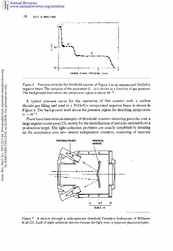
Figure 6 Pressure curve for the threshold counter of Figure 4 in an unseparated 20-GeV/cnegative beam. The variation of the parameter (1 -e) is shown as a function of gas pressure.The background level above the antiproton region is about 10 6.
A typical pressure curve for the operation of this counter with a carbondioxide gas filling and used in a 20-GeV/c unseparated negative beam is shown inFigure 6. The background level above the pressure region for detecting antiprotonsis ~ 10- 6.
There have been several examples of threshold counters detecting particles over alarge angular acceptance (23), mostly for the identification of particles emitted from production target. The light-collection problems are usually simplified by dividingup the acceptance area into several independent counters, consisting of separate
Figure 7 A section through a wide-aperture threshold Cerenkov hodoscope of Williamset al (23). Each of eight spherical mirrors focuses the light onto a separate photomultiplier.
www.annualreviews.org/aronlineAnnual Reviews
Ann
u. R
ev. N
ucl.
Sci.
1973
.23:
1-44
. Dow
nloa
ded
from
arj
ourn
als.
annu
alre
view
s.or
gby
HA
RV
AR
D C
OL
LE
GE
on
02/2
8/05
. For
per
sona
l use
onl
y.

CERENKOV COUNTERS IN HIGH-ENERGY PHYSICS 19
PHOTOI~iULlrlPLIER~ ~
0 0.5
SCALE- m
Fiyure 8 A section through the threshold Cerenkov counter of Ashford et al (23). Theparticles enter from the left and the Cerenkov light produced by electrons is directed outradially by the reflector onto 24 photomultipliers.
mirrors and photomultipliers. A recent example of this type of counter has beenreported by Williams et al (23) and is shown in Figure 7. Each of eight sphericalmirrors (62.5 by 62.5 cm) focuses the Cerenkov light onto a separate photomultiplier.Such a counter can be used as eight separate detectors, or the output may beelectronically added. This counter has been used to separate K + K- states from rr+ ~z-in an experiment using a 15-GeV pion beam at SLAC.
A large threshold Cerenkov counter has been used by Ashford et al (23) fordetecting electrons in experiments of Ke3 decays and hyperon leptonic decays. Asection through the counter is shown in Figure 8. The Cerenkov light emittedin the gas volume is reflected outwards by a sectional parabolic mirror onto a ringof 24 photomultipliers. The detection of pions by this counter was measured to beless than about 0.02~.
4 DIFFERENTIAL CERENKOV COUNTER
The differential Cerenkov counter selects particles of a given velocity by detectingtheir Cerenkov radiation at a fixed angle. As mentioned in section 2.3, the velocityresolution is given by AI3/13 = tan 0A0, where A0 is the total angular acceptance ofthe counter. The design of the differential counter can be separated into two mainclasses depending upon the nature of the radiator ; counters using solid or liquidradiators are thus distinguished from counters using a gas radiator.
4.1 Differential Counter Usin(j a Solid or Liquid Radiator
For low-energy particles having ~ < 5, the required refractive index at thresholdmust be greater than n = 1.02, which is inconveniently in the range of compressed
www.annualreviews.org/aronlineAnnual Reviews
Ann
u. R
ev. N
ucl.
Sci.
1973
.23:
1-44
. Dow
nloa
ded
from
arj
ourn
als.
annu
alre
view
s.or
gby
HA
RV
AR
D C
OL
LE
GE
on
02/2
8/05
. For
per
sona
l use
onl
y.
20 LITT & MEUNIER
gases. As a consequence of the low value of 7, only a modest velocity resolutionof the order of 10-2 to 10-3 is needed to achieve mass separation of the particles.Thus a solid or liquid material can be considered as the radiator for a differentialcounter.
The first optical systems for Cerenkov counters were proposed by Getting (24) anddiscussed in detail in the review by Jelley (3). Several focusing counters have beenmade using solid or liquid radiators (25). The early counters not only suffered froma poor velocity resolution, but also had a fairly small sensitive area. There followedseveral designs for counters that could operate in wide particle beams by meansof focusing the Cerenkov light (26).
Solid or liquid radiators are available over a range of refractive index, althoughthey cannot be tuned as easily as by varying the pressure of a gas. Therefore,attempts have been made to build an optical system of variable focal length tofocus the Cerenkov light emerging from the radiator onto an annular diaphragm.This provides a means of tuning the velocity setting around the value of the refractiveindex of the radiator.
For some differential counters operating with a small angular spread in an experi-ment where multiple scattering and energy loss effects are quite small, often themain contribution to the resolution of the counter is the effect of the dispersion in theradiator. This situation can be improved by compensating for the dispersion bymeans of an achromatic optical system. The general conditions for achromaticoptics in Cerenkov detectors were derived by Frank (27) using refraction and reflec-tion at the interface between different media.
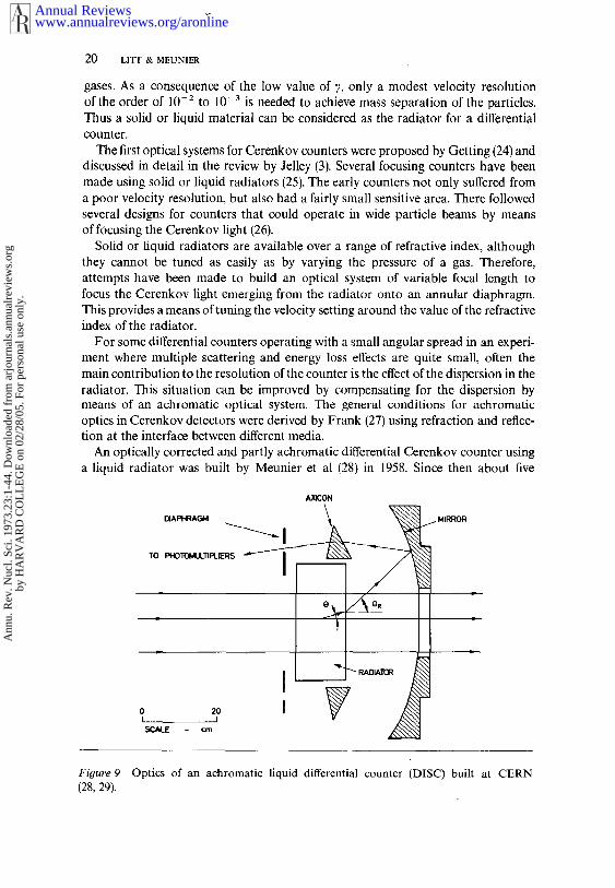
An optically corrected and partly achromatic differential Cerenkov counter usinga liquid radiator was built by Meunier et al (28) in 1958. Since then about five
AXICON
TO PHOTOIdI~TIPLIERS ~
I
L/1
0 2OI I.~,~d. E crn
.~. MIRROR
Figure 9 Optics of an achromatic liquid differential counter (DISC) built at CERN(28, 29).
www.annualreviews.org/aronlineAnnual Reviews
Ann
u. R
ev. N
ucl.
Sci.
1973
.23:
1-44
. Dow
nloa
ded
from
arj
ourn
als.
annu
alre
view
s.or
gby
HA
RV
AR
D C
OL
LE
GE
on
02/2
8/05
. For
per
sona
l use
onl
y.

CERENKOV COUNTERS IN HIGH-ENERGY PHYSICS 21
different designs based upon the same principle have been used in experiments atCERN (11, 29). Their design incorporates an exchangeable liquid radiator cellcovering a range of refractive index of about 5~ (from n ~ 1.55 with high-indexliquids, to n from 1.33-1.40 with water-glycerine mixtures, to n m 1.28 using low-index liquids such as FC75). This type of detector has come to be known as DISC Cerenkov counter (differential isochronous self-collimating).
The principle of the design for the largest liquid DISC cot.~nter is shown inFigure 9. The liquid radiator FC75 is contained in a thin cell having a fused silicawindow. The Cerenkov light is focused by a toroidal mirror of 50-cm radius andpasses through a ring-shaped prism onto the aperture of a diaphragm. The lightpassing through the aperture of the diaphragm is detected by four photomultipliersin coincidence. The ring prism is an axicon lens, that is, it has two conical facesthat are described by rotating straight lines around a common optical axis. Theaxicon not only deflects the Cerenkov light but also compensates for the spread in thecone of light due to dispersion in the radiator.
The light emerging from the exit of the radiator travels at some angle 0R, whichis the refracted Cerenkov angle and not the true Cerenkov angle 0 in the radiator.Hence, there exists a relation between OR and fl given by
tan 0 = /~ sin OR 33.
and hence, from the Cerenkov relation 1, becomes:
sin2 OR = n2 --(1/fl2) 34.
The optical aberrations in this type of counter have to be carefully minimized.The requirements of the optics are that for a single displacement of the axicon lensalong the axis: (a) the focal length is altered to cover a range of OR, (b) the focallength remains fixed, (c) geometric aberrations are corrected, and (d) chromaticaberrations are corrected. These requirements have been met in the design of thetoroidal mirror and axlcon lens. The necessary optical precision can be obtainedusing a mirror and lens made of plastic.
The counter shown in Figure 9 focuses a small angular interval within the rangefrom 40.5° < 0R < 50.6°, and is tuned to a given velocity by moving the positionof the axicon relative to the mirror. Thus, the counter can operate over a range of/~ values:
i.e. using FC75 0.91 < fl < 0.97water 0.85 < fl < 0.94
pentane 0.83 < fl < 0.88
The range covered indicates that these counters are used at beam momentagenerally below about 5 GeV/c. Another design has been made for the detection oflow mass particles (i.e. electrons, muons, and pions) where the // values close unity are encompassed using an angular range from 54.9 < 0~ < 60.3.
The velocity resolution for this type of counter, by differentiating equation 34, isgiven by
dfl =/~3 sin O~ cos O~ dO~ 35.
www.annualreviews.org/aronlineAnnual Reviews
Ann
u. R
ev. N
ucl.
Sci.
1973
.23:
1-44
. Dow
nloa
ded
from
arj
ourn
als.
annu
alre
view
s.or
gby
HA
RV
AR
D C
OL
LE
GE
on
02/2
8/05
. For
per
sona
l use
onl
y.

22 LITT & MEUNIER
The range of angular acceptance d0R is chosen by adjusting a variable aperturediaphragm. With an angular setting of dog ~ 10 mrad, the velocity resolutionbecomes approximately Aft ~ 5 x 10 3.
For detecting low-energy particles, the energy loss in the radiator produces asignificant deterioration in the performance of the DISC counter. ~is effect wascorrected in the multicell DISC counter of Fischer ¢t al (11) in which each cells was filled with a liquid of slightly different refractive index n~ so that therefracted angle 0R was kept constant according to the relation :
n~ = sin 2 0R + (1/fl~) 36.
For these DISC counters a typical optical resolution (d0R) has been about 1 mradfor the smallest diaphragm aperture size of 0.2 mm. Hen~, if we neglect multiplescattering effects and assume that the axicon produces perfect chromatic correction,this type of counter can produce velocity resolutions approaching Aft values of~5 x 10-~.
In the design of a differential Cerenkov counter using solid or liquid radiatorsthere are s¢wral important parameters to be chosen:
1. The velocity resolution with no chromatic correction is, from equation 34,given by
AfllA2 = - flan(AnlA2) 37.
~is should be as small as possible, and should not depend upon other geometricfactors (such as the range of 0) in a well-chosen configuration.
2. The largest divergen~ angle should be chosen for a given velocity resolution.~e Cerenkov angle 0 and refracted angle 0R are related in equation 33, whichcan be rewritten as
AO = (Afl/fl2)[n 2 -(1/f12)] * 38.
Hence the angular acceptan~ depends only upon fl and n, and not on desi~parameters of the counter such as 0.
3. The effect of multiple scattering on the velocity resolution from equations 6, 7,~d 18 can bc expressed as
Afl/fl = tan 0 AOMsc = (15n/p)(N/AX)~ 39.
which is proportional to the refractive index n.Hence, from the above three points the optimization of the counter design does
not depend directly upon the range of the angle OR, but only upon the values of fl, n,and An. ~e best choice for a liquid will have the smallest value of n andThus the design of the counter begins with the choice of the radiator, and thenthe required velocity range determines the range of OR of the optics.
~e fluorocarbons are commonly used in these counters due to their lowdispersion and transparency at ultraviolet wavelengths. The main disadv~tages ofthese liquids are the high density (multiple scattering) and immisdbility with otherliquids.
In some applications (30) a liquid with a low index of refraction, and hen~
www.annualreviews.org/aronlineAnnual Reviews
Ann
u. R
ev. N
ucl.
Sci.
1973
.23:
1-44
. Dow
nloa
ded
from
arj
ourn
als.
annu
alre
view
s.or
gby
HA
RV
AR
D C
OL
LE
GE
on
02/2
8/05
. For
per
sona
l use
onl
y.

CERENKOV COUNTERS IN HIGH-ENERGY PHYSICS 23
low multiple scattering, is used, even though this involves some technical problemsin building the counter. In this respect liquid hydrogen (n- 1.11) and liquiddeuterium (n = 1.13)have been used as radiators. The increase in angular acceptanceof a liquid hydrogen counter as compared with using FC75 would, from equation 39,be a factor of 1.7.
At the upper momentum limit for the liquid or solid radiator differentialCerenkov counter, at say 5 GeV/c, the velocity resolution Aft ~ 5 x l0-3 can betypical. If the counter is filled with liquid EC75 an angular acceptance at thehighest resolution of about 6 mrad can be used--which is about the size of thedivergence of typical secondary beams at these momenta. This type of counter is notsuitable for application at higher energies.
4.2 Differential Gas Counter
To separate pions and kaons in a high-energy beam of, say, 100 GeV/c requiresa velocity resolution of about 10-5. Such a resolution can be obtained with adifferential gas Cerenkov counter. At these high energies the effects of multiplescattering and energy loss become less important, and the main contribution to thevelocity resolution is due to the dispersion in the radiator.
The differential gas counter contains a spherical lens that focuses the cone ofCerenkov light onto an adjustable annular diaphragm. The light passing throughthe aperture is detected by a number of photomultipliers in coincidence. Severaldifferential gas Cerenkov counters have been built (31) with velocity resolutions about 10-4. Even better resolutions can be achieved by using small values of0 and
The chromatic spread of the Cerenkov light AOD~Sp due to dispersion is given by
AODIs~ = (0/2v)[1 +(1/~202)] 40.where v is defined as in equation 14. If we assume that this is the largest errorin the image, the effect of the dispersion error on the velocity resolution is given by
A/~//~ = tan 0 AODIs~ ~ (02/2V) (1/2vy2) 41.
Using equation 8, the maximum value of the Cerenkov angle is thus defined by
02Iv <~ [(1/p2) (rn~z -- m~)] -- (1/vy2) 42.
In this approximation, the design formulae for the differential gas Cerenkovcounter simplify to :
0 <~ 1 [v(m[ -- m~)-- m~]~
L 43.A Lv(m~--~)- mid(Afl/fl)LI.,T = 02/2v
where the subscript i refers to the particle (0 or 1) being detected by the counter.The ultimate resolution using this type of counter is achieved by using the least
www.annualreviews.org/aronlineAnnual Reviews
Ann
u. R
ev. N
ucl.
Sci.
1973
.23:
1-44
. Dow
nloa
ded
from
arj
ourn
als.
annu
alre
view
s.or
gby
HA
RV
AR
D C
OL
LE
GE
on
02/2
8/05
. For
per
sona
l use
onl
y.
24 LITT & MEUNIER
DIAPtI~C-M PR~ V~SSEI.
/
PHOTOfaULTIPLIERS SPHERICAL
0 0,5
SCALE - m
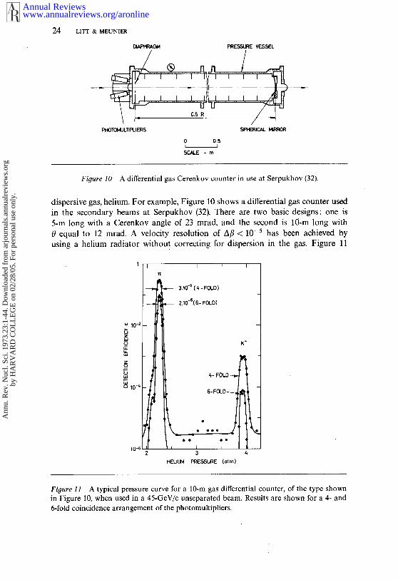
Figure 10 A differential gas Cerenkov counter in use at Serpukhov (32).
dispersive gas, helium. For example, Figure 10 shows a differential gas counter usedin the secondary beams at Serpukhov (32). There are two basic designs: one 5-m long with a Cerenkov angle of 23 mrad, and the second is 10-m long with0 equal to 12 mrad. A velocity resolution of Aft < 10-2 has been achieved byusing a helium radiator without correcting for dispersion in the gas. Figure 11
- ~ 3.10-~ ( 4 - FOLD)
- ~ 2.10"616- FOLD)
4- FOLD
6-FOLD~ ~
=
3
HELILJNI PRESSURE (arm)
Figure 11 A typical pressure curve for a 10-m gas differential counter, of the type shownin Figure i0, when used in a 45-GeV/c unseparated beam. Results are shown for a 4- and6-fold coincidence arrangement of the photomultipliers.
www.annualreviews.org/aronlineAnnual Reviews
Ann
u. R
ev. N
ucl.
Sci.
1973
.23:
1-44
. Dow
nloa
ded
from
arj
ourn
als.
annu
alre
view
s.or
gby
HA
RV
AR
D C
OL
LE
GE
on
02/2
8/05
. For
per
sona
l use
onl
y.

CERENKOV COUNTERS IN HIGH-ENERGY PHYSICS
shows a typical pressure curve for the 10-m counter when used in a 45-GeV/cbeam of pions and kaons. The variation of the detection efficiency is shown whenthe outputs of the 6 photomultipliers are placed into 6- and 4-fold coincidencearrangements. A background level of better than 1 in l0 6 can be routinely obtainedwith these counters.
4.3 Optically Corrected Gas Differential Counter
It is possible to design optics for the differential gas counter that will correct for thedispersion error by a factor of about 15. This achromatic gas counter (DISC) makesit possible to envisage resolutions in the region of Aft ~ 10-6 to 10-v.
In the differential counter the length of the radiator approximately defines thefocal length of the optics. For an acceptable level of.detection efficiency and goodbackground rejection (see section 6.1 for further details) at least 24 photoelectronsshould be detected by the photomultipliers. Thus, with the length and Cerenl~ovangle known, it remains to define the required amount of chromatic correctionand the range of adjustment of the correction needed for a particular application.Although the correction optics are an added complication, they do provide a counterthat can operate over a wide range of operating beam momenta and detectparticles over a large mass range. For certain applications, such as in hyperonphysics where the constraint on the counter length is severe, it is necessary to use aspecially designed achromatic counter.
The required amount of chromatic correction, as given in equation 40, is afunction of the velocity of the particle. This variation can be achieved by movingthe correction element along the axis of the counter. There is a fairly wide choice ofoptical configurations that can achieve the correction. The choic~ is dictated byfactors such as complexity of manufacture, number of lens elements, and avail-ability of optical materials.
For a Cerenkov counter the optics must be ultraviolet-transmitting, whichexcludes all optical glasses except fused silica. There are also some monocrystalswhich can be used such as NaC1, KC1, CaF~, and LiF. However, only NaC1 andKCI have a suitable dispersion compared with that of fused silica, and are avail-able in large sizes (up to 350-ram diameter) at a reasonable cost.
Chromatic correction implies that refracting optics will be needed. One cancontemplate a design with a single element of fused silica which, in conjunctionwith a mirror, must have a positive power. However, this combination cannot betuned to correct over a variable range of chromatism, since the velocity setting ofthe counter would be affected simultaneously by the corrector lens position and thegas pressure. This solution was possible for the liquid DISC counter (28) becausethe refractive index in this instance could not be varied. The large Cerenkov angleand the use of an axicon lens in the liquid DISC counter allows the focus to bemaintained at a fixed position within an accuracy acceptable for this counter atenergies up to about 5 GeV.
The required accuracy for the gas DISC counter is more than two orders ofmagnitude more precise than for the liquid DISC. The chromatic correction hasto be applied in a way that is proportional to (n-1). It is desirable to have
www.annualreviews.org/aronlineAnnual Reviews
Ann
u. R
ev. N
ucl.
Sci.
1973
.23:
1-44
. Dow
nloa
ded
from
arj
ourn
als.
annu
alre
view
s.or
gby
HA
RV
AR
D C
OL
LE
GE
on
02/2
8/05
. For
per
sona
l use
onl
y.
26 LITT & MEUNIER
counter in which the tuning of the velocity setting is independent of the setting ofthe chromatic corrector. Also, the chromatic corrector should not affect to firstorder the focal length of the optics for the mean wavelength, irrespective of itslongitudinal position, so that the diaphragm can be located at a fixed position.Thus a corrector of zero power, is required. One must also incorporate into thedesign of the corrector the possibility of minimizing longitudinal chromaticaberrations, spherical aberrations, coma, and astigmatism.
The design variables are the curvature, thickness, and positions of all the lenses.The optimization of the design has been performed through a detailed study ofray-tracing for a range of particle velocities, wavelength bandwidths, and correctorpositions. In this way an error matrix is developed which must be carefully studiedin relation to the effect of these residual errors on the performance of a specificdetector.
One type of design that has been shown to be a0aenable to satisfactorycorrection over large variations in the design Cerenkov angle from 20 to 120 mradconsists essentially of four elements:
1. A mirror, which is aspheric for counters with small values of Cerenkov angle,and of the Mangin-type for larger angles.
2. A single fused silica lens which, together with the mirror, corrects most of thegeometric aberrations. This element also transforms the optics into a telecentricsystem in which the entrance pupil is at infinity, thus allowing for the stability ofthe Cerenkov angle even in the presence of some defocusing.
3. A chromatic corrector element (which is a doublet, or preferably a triplet, offused silica and sodium chloride), which cancels the variation of chromatism bydisplacement along the counter axis. This element does not affect the velocity settingof the counter.
4. Field lenses of fused silica, used as exit windows, which transfer the lightpassing through the diaphragm aperture onto the photocathode area of thephotomultipliers.
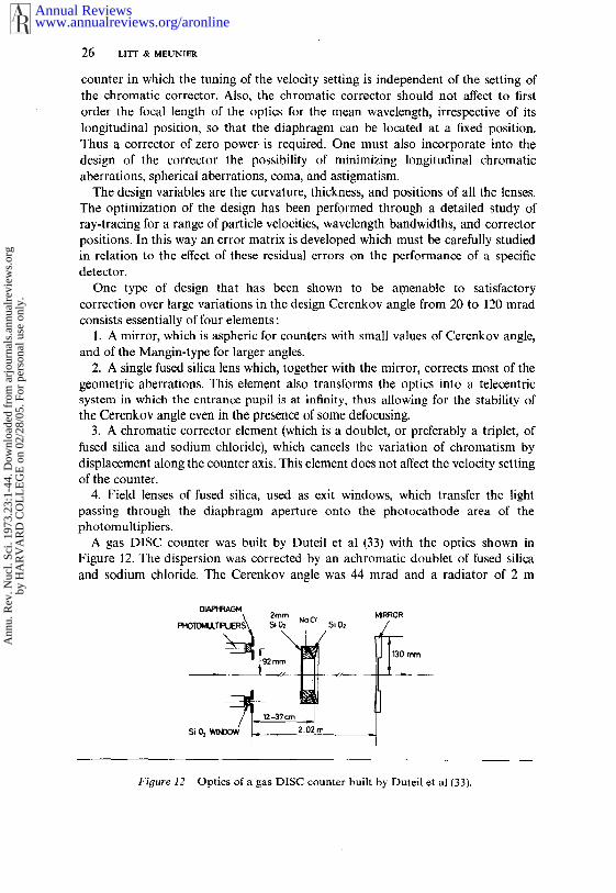
A gas DISC counter was built by Duteil et al (33) with the optics shown Figure 12. The dispersion was corrected by an achromatic doublet of fused silicaand sodium chloride. The Cerenkov angle was 44 mrad and a radiator of 2 m
PHOTOMULT1PLIERS~~i~0~ m NaCl 5i0~
SiOz W~3OW .- ’
MIRROR
Figure 12 Optics of a gas DISC counter built by Duteil et al (33).
www.annualreviews.org/aronlineAnnual Reviews
Ann
u. R
ev. N
ucl.
Sci.
1973
.23:
1-44
. Dow
nloa
ded
from
arj
ourn
als.
annu
alre
view
s.or
gby
HA
RV
AR
D C
OL
LE
GE
on
02/2
8/05
. For
per
sona
l use
onl
y.

CERENKOV COUNTERS IN HIGH-ENERGY PHYSICS
~PrlOTOIdLILTIPLIER~
~ Dt~PHI~Cq~I
I I 0 10 20
27
Figure 13 A gas DISC counter used in the 20-GeV charged hyperon beam at CERN (34).
nitrogen (or carbon dioxide) gas was used. A velocity resolution of better than10-5 was achieved with this counter.
An optically corrected gas differential counter operating (34) in the chargedhyperon beam at the CERN proton synchrotron is shown in Figure 13. Theapplication of this counter to hyperon physics demanded a high velocity resolutionsince the Z- and E- particles are close in mass, and the length had to beminimized because the 5-- half-life is only ~57 crn at 20 GeV. Two counters werebuilt with a limiting velocity resolution of 5 × 10- 5 covering the range of/~ from0.993 to 1.000. The short length was achieved by using a Cerenkov angle of120 mrad, providing sufficient light in a counter external length of 41 cm.
At this large Cerenkov angle, without optical correction, the geometric aberra-tion would limit the velocity resolution to 2 × 10⁻⁴. The chromatic dispersion alonewould limit the velocity resolution to 2×10⁻⁴ at /~= 1.000, and 4×10⁻⁴ at/~ = 0.993. Since these aberrations are of similar importance, the optics were designedto simultaneously minimizc both effects. This was achieved with a designincorporating 6 lenses into a 3-element system, and using spherical surfaces. AMangin-type mirror was used, consisting of a rear-surfaced aluminized negativemeniscus and a single positive meniscus lens. This component removes most of thegeometric aberration. A chromatic corrector triplet, which moves along the counteraxis to cover the range of/~, corrects for the dispersion in the gas radiator. Anamount of longitudinal chromatism produced by the chromatic triplet is canceled byintroducing a similar amount, but with opposite sign, in the mirror. By a carefulevaluation of the correction optics it has been possible to reduce the velocityresolution down to the order of A/3 ~ 5 × 10-~. A typical pressure curve for thisDISC counter is shown in Figure 14.
www.annualreviews.org/aronlineAnnual Reviews
Ann
u. R
ev. N
ucl.
Sci.
1973
.23:
1-44
. Dow
nloa
ded
from
arj
ourn
als.
annu
alre
view
s.or
gby
HA
RV
AR
D C
OL
LE
GE
on
02/2
8/05
. For
per
sona
l use
onl
y.

2~ LITT & MEUNIER
An optically corrected counter is presently under construction for use in thehigh-energy beams at the NAL and CERN SPS multihundred GeV accelerators.This counter is 5-m long, contains helium gas, and uses a Cerenkov angle of
10+.
10z
10~ I1.000 0.gg8 0.996
RELATIVE VELOCITY p (=v/c)
Figure 14
DIAPHRAGM
R=Z35 m
A pressure curve for the DISC counter shown in Figure 13.
29.5cm
4.51 m
MIRROR
Figure 15 Optics for a gas DISC counter which is to be used in the multihundred GeVbeams at NAL and the CERN SPS.
www.annualreviews.org/aronlineAnnual Reviews
Ann
u. R
ev. N
ucl.
Sci.
1973
.23:
1-44
. Dow
nloa
ded
from
arj
ourn
als.
annu
alre
view
s.or
gby
HA
RV
AR
D C
OL
LE
GE
on
02/2
8/05
. For
per
sona
l use
onl
y.

CERENKOV COUNTERS IN HIi3H-ENERGY PHYSICS 29
24.5 mrad. The optics are shown in Figure 15. This counter, which is of the typeB outlined in Ref. 35, is designed for a velocity resolution of about 4 x 10⁻⁷, whichshould be capable of distinguishing between pions and kaons in unseparated beamsup to about 250 GeV/c. The focusing errors in this counter are about five timeslarger than the diffraction limit.
It is not so simple to present design equations for the optically correct~ldifferential counters since the correction involves the simultaneous minimizationof several kinds of aberrations. However, by studying the several counters alreadyin operation it appears that the limiting velocity resolution is approximatelyequivalent to having a diaphragm aperture setting that is close to Ar ~ 0.1 mm(+50~). Hence from this approximate experimental fact, the limiting velocityresolution can be expressed as
(Afl/fl)LiMl T ~- tan 0 AOLIM1T ~ O(Ar/L) 44.
where L is the counter length. Using equations 6, 8, and 44, it is possible to derivean approximate set of design equations for the optically corrected gas differentialcounter :
0 <~ [N(rn2~ - mZo)/(2AArpZ)]÷
L >~ [N/a]÷[ZArp2)/(m~-- m~)]~ 45.
(A/3//~)LIMIT (AO3ar/s)
5 COMPARISON OF THRESHOLD AND DIFFERENTIALCERENKOV COUNTERS
In sections 3 and 4 the design parameters of the threshold and differentialCerenkov counters have been expressed in the form of equations. A comparisonof these parameters for counters at high energies, that is for gas counters, is shownin a graphical form (14) in Figures 16-18. The parameters have been calculatedusing equations 32, 43, and 45. Included in two of these figures are the parametersof four Cerenkov counters presently in operatio~ (32, 34, 36) and three counterscurrently being designed for use at the CERN SPS (35). The parameters of theseselected counters are given in Table 3.
For the curves representing the differential Cerenkov counter, typical values havebeen used for the ratio (N/A), as defined in equation 6. The curves for thethreshold counter are shown for electronic detection ineffidencies (1 -e) at the levelof 10-1 to 10-6. The broken regions in the curves denote that the required gaspressures are in excess of 30 atm for helium or nitrogen, and in excess of 20 atmfor the liquefying gas SF6. The scale on the abscissa for two of the figures isdrawn to show the limiting momentum scale for several pairs of particles. Thelimiting momentum is that value at which the velocity resolution of the counter isequal to the velocity difference between the two particles. In general a Cerenkovcounter should not be used at a momentum as high as the limiting value.
Figure 16 shows the maximum values of the Cerenkov angle for the threshold,differential, and DISC types of counter. From equations 32, 43, and 45 the maximum
www.annualreviews.org/aronlineAnnual Reviews
Ann
u. R
ev. N
ucl.
Sci.
1973
.23:
1-44
. Dow
nloa
ded
from
arj
ourn
als.
annu
alre
view
s.or
gby
HA
RV
AR
D C
OL
LE
GE
on
02/2
8/05
. For
per
sona
l use
onl
y.

30 LITT & MEUNIER
www.annualreviews.org/aronlineAnnual Reviews
Ann
u. R
ev. N
ucl.
Sci.
1973
.23:
1-44
. Dow
nloa
ded
from
arj
ourn
als.
annu
alre
view
s.or
gby
HA
RV
AR
D C
OL
LE
GE
on
02/2
8/05
. For
per
sona
l use
onl
y.

CERENKOV COUNTERS IN HIGH-ENERGY PHYSICS 31
EF_AM MOI4~NTUM FO~ LIMITING wK SEPARATION (GeVIc)10 100 1000 10000
! ~ N/A: 0.4CTI IRE~ ~N/A= 0.2~
"J - 1 IHEP(1 }oDIF’E_~ 2 IHEP(~
SPS-,~ *D, SC
~7SPS-ESP$ -(:
BEAM MOMENTUM AT LIMITING RESOLUTION FOR THE SE]OARATION OFPAIRS OF PARTICLES (GeV/c)
Figure 16 Maximum values of the Cerenkov angle for threshold, differential, and DISCtypes of gas counters. The abscissa corresponds to values of the beam momenta at whichthe limiting velocity resolution of each counter is equal to the velocity difference betweenpairs of particles. The seven Cerenkov counters included in this figure are listed andreferenced in Table 3.
values of the angles for these three types of counter scale with the limitingmomentum as p- ~, p- x, and p- ~, respectively.
The variation of the minimum lengths of the three types of Cerenkov countersis illustrated in Figure 17. The minimum lengths scale with limiting momentumas p2, p2, and p4/3 for the threshold, differential, and DISC counters, respectively.If we assume a constant value of (N/A), the minimum lengths of the threshold anddifferential counters are approximately related by
Lr.R~s~ ~ vLD1vv 46.
Thus, even if we allow for a smaller value of N for the threshold counter, the
www.annualreviews.org/aronlineAnnual Reviews
Ann
u. R
ev. N
ucl.
Sci.
1973
.23:
1-44
. Dow
nloa
ded
from
arj
ourn
als.
annu
alre
view
s.or
gby
HA
RV
AR
D C
OL
LE
GE
on
02/2
8/05
. For
per
sona
l use
onl
y.

32 LITT & MEUNIER
0.1
BEAM MOMENTUM FOR LfMITING wK ~ATION (GeV/c)10 100 1000 10000
N/A~0.25cm
MOMENTUM AT LIMITING RESOLUTION FOR ~-IE SEPARATIONOF PAIRS OF PARTICLES (GeV/c)
Figure /7 Variation of the minimum lengths of threshold, differential, and DISC Cercnkovcounters as a function of the beam momentum for the limiting separation of different pairsof particles.
length of the threshold counter will always be several times the length of adifferential counter.
The limiting velocity resolution (Afl/fl)LiMl T is shown as a function of the Cerenkovangle 0 in Figure 18 for the three types of counters. From the design equations,the limiting resolutions for the threshold, differential, and DISC counters scale as(0~2, 02, and 03, respectively.
In summary, the gas threshold Cerenkov is the least expensive counter to buildas it only requires an average-quality optical mirror, a single photomultiplier, andsimple electronic configuration. The counter vessel need only withstand workingpressures from vacuum to a few atmospheres, and only a simple refractive indexmeasurement is needed. However, for a ~ven rejection the threshold counter becomesextremely long as the beam energy increase~, and therefore these counters have apoorer rejection than the differential counters. There can be counting rate problems,
www.annualreviews.org/aronlineAnnual Reviews
Ann
u. R
ev. N
ucl.
Sci.
1973
.23:
1-44
. Dow
nloa
ded
from
arj
ourn
als.
annu
alre
view
s.or
gby
HA
RV
AR
D C
OL
LE
GE
on
02/2
8/05
. For
per
sona
l use
onl
y.
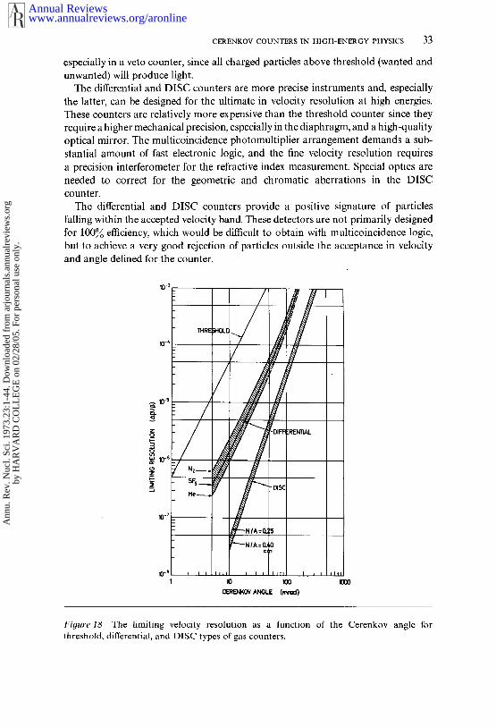
CERENKOV COUNTERS IN HIGH-ENERGY PHYSICS 33
especially in a veto counter, since all charged particles above threshold (wanted andunwanted) will produce light.
The differential and DISC counters are more precise instruments and, especiallythe latter, can be designed for the ultimate in velocity resolution at high energies.These counters are relatively more expensive than the threshold counter since theyrequire a higher mechanical precision, especially in the diaphragm, and a high-qualityoptical mirror. The multicoincidence photomultiplier arrangement demands a sub-stantial amount of fast electronic logic, and the fine velocity resolution requiresa precision interferometer for the refractive index measurement. Special optics areneeded to correct for the geometric and chromatic aberrations in the DISCcounter.
The differential and DISC counters provide a positive signature of particlesfalling within the accepted velocity band. These detectors are not primarily designedfor 100~ efficiency, which would be difficult to obtain with multicoincidence logic,but to achieve a very good rejection of particles outside the acceptance in velocityand angle defined for the counter.
CE~E~KOV AN~LE (mrad)
Figure 18 The limiting velocity resolution as a function of the Cerenkov angle forthreshold, differential, and DISC types of gas counters.
www.annualreviews.org/aronlineAnnual Reviews
Ann
u. R
ev. N
ucl.
Sci.
1973
.23:
1-44
. Dow
nloa
ded
from
arj
ourn
als.
annu
alre
view
s.or
gby
HA
RV
AR
D C
OL
LE
GE
on
02/2
8/05
. For
per
sona
l use
onl
y.

34 LITT & MEUNIER
Threshold counters are generally built to have a good detection efficiency. Thisis especially important for detecting a particle that is not the lightest mass in thebeam. In this case one threshold counter must be used as a veto signal to rejectthe lighter particles.
At their limiting resolutions the differential and DISC counters have a morerestricted angular acceptance than the threshold counter. However, the limiting,resolution is needed only in exceptional cases where one is prepared to tradeacceptance for resolution.
6 PATTERN RECOGNITION IN A FOCUSINGCERENKOV COUNTER
6.1 Rin9 Image Detector
An objective lens using spherical optics will transform Cerenkov light rays emittedat an angle 0(2) along a particle trajectory into a ring image of radius r in the focalplane of the lens, as shown in Figure 19, such that
r = ftan 0(2) 47.
wherefis the focal length of the lens.The image may suffer from optical aberrations which, if required, can be corrected
by using refracting optics such that the quantity dr/d2 becomes zero. The Cerenkovphrtons emitted by the passage of the charged particle will be distributed aroundthe ring image which will then be transformed into a smaller number of photo-electrons by the photodetector. From the geometry of the light dots in the focalplane the velocity and direction of the particle can be obtained. There is thereforea problem of pattern recognition. The radius of the circle and its center must befound for an image defined by random points with a radial distribution which isnot necessarily Gaussian.
There have been many attempts to record the dots of light directly onto a photo-graphic plate, and such a method has been used when working with a well-focusedbeam of monoenergetic particles (37). To detect light from single events it has beennecessary to use an image intensifier (38). The best and most recent example is Giese et al (38) where a velocity resolution of A/3 = 6 × -7 has been observed
CONk~L WAVE ~ WAVE FOCAL
Figure 19 Principle of ring-focusing of Cerenkov light using a spherical lens.
www.annualreviews.org/aronlineAnnual Reviews
Ann
u. R
ev. N
ucl.
Sci.
1973
.23:
1-44
. Dow
nloa
ded
from
arj
ourn
als.
annu
alre
view
s.or
gby
HA
RV
AR
D C
OL
LE
GE
on
02/2
8/05
. For
per
sona
l use
onl
y.

CERENKOV COUNTERS IN HIGH-ENERGY PHYSICS 35
with a systematic error of _+ 2 × 10 7. They used a four-stage cascade image intensifierand recorded the output screen image using photographic film. With a radiator of10-m hdium gas and using 0 = 11.5 mrad they obtained a mean value of 1.8 spotsof light for each particle. From equation 6 this is equivalent to having an A parameterof 13.6 cm-1, which is quite low when compared with photomultiplier detectionbut is due to their restricted wavelength bandwidth from 360 to 480 nm at halfmaximum.
The pattern recognition of a circle requires at least three spots of light, and forthis case the fit is always perfect. Giese et al selected events in which at leastfour spots were evenly spaced around the circumference of the ring, thus reducingthe fraction of good events to 5~. The selection of events in this manner leads tothe above value of the velocity resolution. This is clearly an off-line procedure andis rather slow.
A simple alternate method is to detect the light that passes through an annulardiaphragm placed in front of a photodetector. For detection by a single photo-detector the level of discrimination must be higher than a few photoelectrons soas to reduce the number of spurious noise signals, and there is no guarantee thatthe circle of light does not extend into the opaque part of the diaphragm. Thismethod can produce results for particles that are collinear with the axis, but willnever achieve a very low efficiency for particles that are slightly offset in velocityor collinearity (i.e. it will provide a poor rejection of unwanted events).
An improvement is collection of the light falling outside the annular apertureand using this signal in anticoincidence (39). This method suffers from the difficultythat if the anticoincidence threshold is set very low, even the tail of the lightdistribution that passes through the diaphragm aperture can trigger the anti-coincidence channel and thus reduce the efficiency and the effective aperture of thediaphragm. When analyzing less-abundant particles (such as kaons) close abundant particles (pions), the anticoincidence channel might become overloaded,thus reducing the count rate of the wanted particles. In fact, the anticoincidencemethod has never achieved a very good quality of rejection of unwanted particles.
A more useful method is to fragment the annual diaphragm into several sectors(q), each connected to a photomultiplier. It can be required that all sectors (or fraction of the sectors) give an output signal before an event is selected (seeHuq & Hutchinson, 26). With all q photomultipliers in coincidence, the accidentalbackground rate due to spurious noise pulses soon becomes negligible as q increases,even when the photodetectors are set to fire on single photoelectrons. Also the qoutputs can be grouped in parallel, i.e. the outputs from p adjacent photomultipliersare passed into an or circuit, and the outputs from q/p or circuits are arranged incoincidence. These different configurations have different efficiencies e given forexample by
q-fold e = " [1 - exp (- N/q)]q48.
q/p-fold ~(q,p)= [1-exp(-Np/q)]q/p
where N is the average total number of photoelectrons produced. If an on-linerecord is made of the counts in the~e different channels it is possible to continuously
www.annualreviews.org/aronlineAnnual Reviews
Ann
u. R
ev. N
ucl.
Sci.
1973
.23:
1-44
. Dow
nloa
ded
from
arj
ourn
als.
annu
alre
view
s.or
gby
HA
RV
AR
D C
OL
LE
GE
on
02/2
8/05
. For
per
sona
l use
onl
y.

36 LITT & MEUNIER
extract the value of e, and hence N. The background and rejection can also beobtained from the comparison of e(q,p) in the region of the mass spectrumbetween the particle peaks.
The efficiency for the q-fold coincidence requirements (i.e. assuming p = 1) shown in Table 4 as a function of the value N. These efficiencies are generally atthe level of 70 to 90~. A higher efficiency can be obtained by using a longercounter, but this is not a recommended choice in view of the fast rising cost andthe increased amount of material in the beam.
Table 4 Electronic detection efficiencies for different values of the q-fold coincidenceand for values of the average number of photoelectrons N, calculated using equation 48assuming p = 1.
Effleieneies N = 12 N = 24 N = 48
q = 3 fold
4
6
8
0.946
0.815
0.418
0.133
0.999
0.990
0.855
0.665
1.000
1.000
0.998
0.985
The slope of the velodty resolution curve increases as the value of q is increased.For q > 4, a q-fold coincidence signal implies that the light ring must be com-pletely included in the diaphragm aperture. It is only this configuration that makesthe counter self-collimating, that is, insensitive to particles having a divergencegreater than A0/2.
The expected response of a differential or DISC counter versus the number ofcoincidences q, the total number of photoelectrons N, and the diaphragm angularaperture D (expressed in units of the width of the light spread (A0)) has computed (15), and a sample of the results is shown in Figure 20. A Poissondistribution is assumed for the distribution of N and for the radial distributionof the intensity of the ring image. Although this assumption is a reasonable approxi-mation of the spread due to multiple scattering and geometric aberrations, it is notstrictly valid for the chromatic spread in an uncorrected differential counter, noris it true for the residual chromatic spectrum in a DISC counter. However, theresults of the analysis do provide some conclusions that are in agreement with theexperience of running these detectors:
1. The slope of the sides of the peaks is governed by the magnitude of the angularspread (A0> of the light distribution, and is practically independent of q.
2. The width of the curves depends strongly upon q.3. The detection efficiency on the peak shows a developing plateau ohly when
the diaphragm angular aperture D is set at more than twice the angular spread(A0) of the light.
4. It is rather misleading to quote the velocity resolution as the width at half-height of the detection efficiency curves. An ideal Cerenkov counter would present
www.annualreviews.org/aronlineAnnual Reviews
Ann
u. R
ev. N
ucl.
Sci.
1973
.23:
1-44
. Dow
nloa
ded
from
arj
ourn
als.
annu
alre
view
s.or
gby
HA
RV
AR
D C
OL
LE
GE
on
02/2
8/05
. For
per
sona
l use
onl
y.

~ ~o~__-
-5
N =25~=2
CERENKOV COUNTERS IN HIGH-ENERGY PHYSICS
a)
~ E N=25 q:8 p:l
0 .5
D=
-I.0
-1.5
-5 0 +,5
~3-~o/(tan 9 <A9>)
37
Fi#ure 20 Calculated response curves for a differential or DISC Cerenkov counter as afunction of the number of inputs (q/p) to the coincidence circuit and angular aperture ofthe diaphragm setting (D). The abscissa is a velocity-difference scale expressed in units the velocity resolution of the counter. N is the number of photoelectrons detected by thetotal number (q) of photomultipliers.
a rectangular response curve, with a flat top, and would be capable of rejectingparticles to the side even with a large width of the curve.
From curves similar to those shown in Figure 20 it is apparent ~at a goodcompromise for the working conditions is setting the diaphragm at two or threetimes the value of (A0), and choosing the total number of the groupings (q/p) ofthe photomultipliers to be greater than about 6. This compromise ensures thatthere is a s~nall plateau region on the top of the efficiency curve, with an efficiencyas given by equation 48, and that there is no sizable degradation of the massresolving power of the counter. If the value of q is 6 or 8, from Table 4 one canconclude that a value of N of about 24 is recommended to obtain an acceptablecounting efficiency.
Actual experimental results can be illustrated by the pressure curve of theIHEP 5-m differential counter (32). Figure 21 shows the counting efficiency curvesfor two settings of the diaphragm aperture as a function of the number (q/p) ofinputs into the coincidence arrangement.
6.2 Spot Image Detector
Another possibility for electronic pattern recognition is focusing the Cerenkov lightfrom a single particle to form a single dot of light, a technique which has beenapplied since the start of the development of Cerenkov counters (24, 40). Thefocusing conditions for a dot are such that for a narrow particle beam they are
www.annualreviews.org/aronlineAnnual Reviews
Ann
u. R
ev. N
ucl.
Sci.
1973
.23:
1-44
. Dow
nloa
ded
from
arj
ourn
als.
annu
alre
view
s.or
gby
HA
RV
AR
D C
OL
LE
GE
on
02/2
8/05
. For
per
sona
l use
onl
y.

38 LITT & MEUNIER
10-4
b)
3-FOLD
6 -FOLD
Fioure 21 Pressure curves for the IHEP 5-m differential Cerenkov counter (32) illustrating
quali~y of detection, and rejection of unwanted events, in an unseparated 40-GeV/c negativebeam. The detection efficiency is shown as a function of the number of inputs into thecoincidence arrangement for the two diaphragm slit settings of (a) 1.6 mm and (b) 3.2
approximately obtained through the use of conical, cylindrical, or more complicatedrevolution~surfaces, all having a singular point on the axis. This focusing, althoughapproximate, was sufficient for the precision required from liquid or solid radiatorswith particles of about 100 MeV. For particles outside the velocity acceptance bandthe spot enlarges and falls outside the region defined by a circular diaphragm.
The spot-focusing idea h as been recently revived in a computer study of a proposed
Figure 22 The principle of the spot-focusing of Cerenkov light using an axiconic lens toproduce a plane wavefront, followed by a spherical lens to form the final point image inthe focal plane.
www.annualreviews.org/aronlineAnnual Reviews
Ann
u. R
ev. N
ucl.
Sci.
1973
.23:
1-44
. Dow
nloa
ded
from
arj
ourn
als.
annu
alre
view
s.or
gby
HA
RV
AR
D C
OL
LE
GE
on
02/2
8/05
. For
per
sona
l use
onl
y.

CERENKOV COUNTERS IN HIGH-ENERGY PHYSICS 39
counter design by Benot et al (41). The principle of the counter optics illustrated in Figure 22. The conical wavefront of the Cerenkov light is convertedinto a plane wavefront using an axicon lens, and the final image is formed by aspherical lens. The counter can detect multiparticle production as long as the positionof the target coincides with the position of the apex of the axicon (or a virtualimage of the axicon). The Cerenkov light from a particle of velocity flo is focusedto a spot, whereas light from a particle of vclocity different from flo produces aring image. Benot et al have studied a possible design for this type of detectorwhich, assuming a production target of 1-mm radius, is capable of providing theangular coordinates ofmultiparticles to _+ 0.1 mrad and the velocities (in the range of70 < 7 < 400) to Aft ~ 2 x 10- 6.
The spot-focusing idea offers the possibility of simultaneously detecting the particlevelocity and direction. This is a clear advantage over the crude pattern recognitionafforded by the single annular diaphragm of a differential Cerenkov counter.
6.3 Multiplexed Cerenkov Counter
The restricted phase-space acceptance of a differential counter with a singlediaphragm is a drawback in the measurement of particles coming from an extendedphase space (large target size). One way to obtain more data on each event is multiplex the output of the Cerenkov counter.
A six-channel Cerenkov counter (42) using a specially zoned mirror has been usedin a precision measurement of the pion-proton total cross section (43). As shown Figure 23, the Cerenkov light is focused by a spherical mirror into a ring imageat the focal plane. A special spherical mirror is placed in the focal plane to focus thelight from each of the six zones onto pairs of photomultipliers connected incoincidence. A particle traveling along the optical axis of the counter, and producingCerenkov light at an angle 0, will form a ring image at the focal plane of radiusr =ftan 0, and centered on the point 0. If a particle enters the counter at an angle~ with rcspect to thc optical axis, the center of the ring image is displaced to the
PHOTOMULTIPLERS ~
DIAPHRAGM - ~ TMIRRORS 1 m RING ZONES OF THE
DIAPHRAGM - MIRRORS
a) b)
Figure 23 A six-channel Cerenkov counter built by Ivanov et al (42) in which Cerenkovlight is focused onto special diaphragm-mirrors in the focal plane of the counter optics.Using a suitable electronic logic between the light outputs from each ring zone of thediaphragm-mirrors it is possible to determine the angle of each incoming particle.
www.annualreviews.org/aronlineAnnual Reviews
Ann
u. R
ev. N
ucl.
Sci.
1973
.23:
1-44
. Dow
nloa
ded
from
arj
ourn
als.
annu
alre
view
s.or
gby
HA
RV
AR
D C
OL
LE
GE
on
02/2
8/05
. For
per
sona
l use
onl
y.
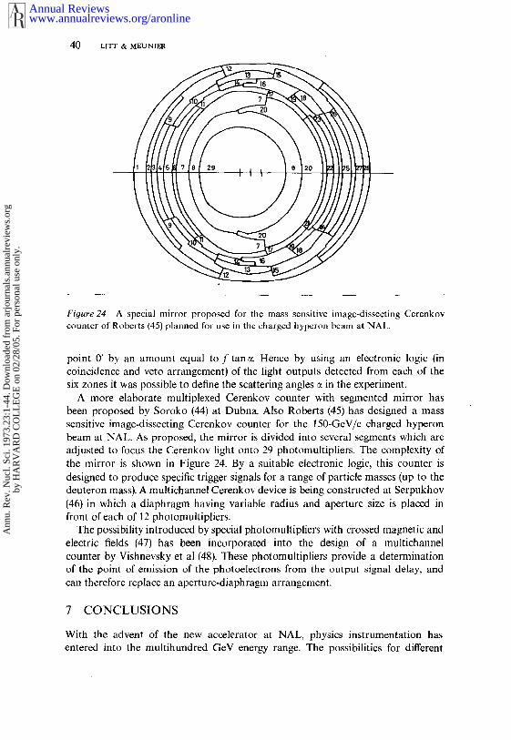
4O LITT & MEUNIER
Figure 24 A special mirror proposed for the mass sensitive image-dissecting Cerenkovcounter of Roberts (45) planned for use in the charged hyperon beam at NAL.
point 0’ by an amount equal to f tan ~. Hence by using an electronic logic (incoincidence and veto arrangement) of the light outputs detected from each of thesix zones it was possible to define the scattering angles ~ in the experiment.
A more elaborate multiplexed Cerenkov counter with segmented mirror hasbeen proposed by Soroko (44) at Dubna. Also Roberts (45) has designed a sensitive image-dissecting Cerenkov counter for the 150-GeV/c charged hyperonbeam at NAL. As proposed, the mirror is divided into several segments which areadjusted to focus the Cerenkov light onto 29 photomultipliers. The complexity ofthe mirror is shown in Figure 24. By a suitable electronic logic, this counter isdesigned to produce specific trigger signals for a range of particle masses (up to thedeuteron mass). A multichannel Cerenkov device is being constructed at Serpukhov(46) in which a diaphragm having variable radius and aperture size is placed front of each of 12 photomultipliers.
The possibility introduced by special photomultipliers with crossed magnetic andelectric fields (47) has been incorporated into the design of a multichannelcounter by Vishnevsky et al (48). These photomultipliers provide a determinationof the point of emission of the photoelectrons from the output signal delay, andcan therefore replace an aperture-diaphragm arrangement.
7 CONCLUSIONS
With the advent of the new accelerator at NAL, physics instrumentation hasentered into the multihundred GeV energy range. The possibilities for different
www.annualreviews.org/aronlineAnnual Reviews
Ann
u. R
ev. N
ucl.
Sci.
1973
.23:
1-44
. Dow
nloa
ded
from
arj
ourn
als.
annu
alre
view
s.or
gby
HA
RV
AR
D C
OL
LE
GE
on
02/2
8/05
. For
per
sona
l use
onl
y.

CERENKOV COUNTERS IN HIGH-ENERGY PHYSICS 41
types of particle detectors and identifiers are quite restricted in this new energy range,and will consist mainly of the following devices :
1. Scintillation counters, which provide fast timing (down to ~0.1 nsec) andtrack position information to the accuracy of a few millimeters.
2. Wire chambers, which have a poorer timing accuracy than scintillators butprovide accurate position information [-down to ~0.1 mm for high pressure wirechambers (49) or drift chambers (50)].
3. Total absorption counters or nuclear detectors based upon the emission ofscintillation or Cerenkov light in large-size radiators. Unfortunately these detectorsmake a destructive measurement on the particles but can produce an energydetermination approaching the accuracy of a few percent (51).
4. Ionization detectors based upon the measurement of the relativistic rise of theenergy loss by ionization. This technique is in an early stage of development (52).
5. Transition radiation detectors, which are also in the developmental stage (53),are particularly suited for the detection of high ~ particles. Thus they will be usefulin detecting low-mass particles.
6. Cerenkov counters, which can provide velocity and angular coordinates ofcharged particles over a wide range of masses and beam energies. The effect is wellknown, and counters can be designed with confidence. Due to the large statisticalfluctuation associated with a low light yield, an intensity measurement of Cerenkovradiation provides a rather poor result for single particles and is valid only for alarge group of particles. However, the usefulness of the Cerenkov detector is thatan angular measurement of the light, which is not subject to the effect of statisticalfluctuations, can produce a high accuracy even for single particles.
The limit for the application of the Cerenkov technique at high energies will beestablished by the ability to resolve the velocity of the particle with an accuracythat is going approximately as lip a. In the differential Cerenkov counter the opticalaberrations will set this limit, whereas the DISC counter will be limited eventuallyby the diffraction of light. It appears that practical limits for the application ofCerenkov counters may be reached within the energy range afforded by the newmultihundred GeV accelerators at NAL and CERN.
Literature Cited
1. Cerenkov, P. A. 1934. Dokl. Akad. NaukSSSR 2:451
Vavilov, S. I. 1934. Dokl. Akad. NaukSSSR 2:457; Ibid 1956. SobranieSochinenii (collected works) 4 : 356.Moscow: Izdatel’stvo Akad. NaukSSSR
2. Tamm, I. E., Frank, I. M. 1937. Dokl.Akad. Nauk SSSR 14:1073. Jelley, J. V. 1958. Cerenkov Radiation
And Its Applications. London:Pergamon
Hutchinson, G. W. 1960. Progr. Nucl.Phys. 8 : 197-236
Zrelov, V. P. 1968. Cerenkov RadiationIn High-Energy Physics. Moscow:Atomizdat. 2 vols. (English transl. 1970. lsrael Program Sci. Transl.)
Denisov, S. P. 1971. Advances inCerenkov counters. IHEP Rep.71/47
4. Cerenkov, P. A. 1944. Tr. Fiz. Inst.Akad. Nauk SSSR 2:45. Ginsburg, V. L. 1940. Zh. Eksp. Teor.
Fiz. 10(6): 5896. Pinsky, L. S., Eandi, R. D., Osborne,
W. Z., Rushing, R. B. 1971. XIIInt. Conf Cosmic Rays, Tasmania4 : 1630-34
www.annualreviews.org/aronlineAnnual Reviews
Ann
u. R
ev. N
ucl.
Sci.
1973
.23:
1-44
. Dow
nloa
ded
from
arj
ourn
als.
annu
alre
view
s.or
gby
HA
RV
AR
D C
OL
LE
GE
on
02/2
8/05
. For
per
sona
l use
onl
y.

42 LITT & MEUNIER
7. Lakes, R. S., Poultney, S. K. 1971.Appl. Opt. 10:797-800
8. Duteil, P., Garron, J. P., Meunier, R.,Stroot, J. P., Spighel, M. 1968.CERN Rep. 68/14
Yovanovitch, D. D. et al 1971. Nucl.lnstrum. Methods 94 : 477-80
9. Vovenko, A. S. et al 1964. Soy. Phys.Usp. 6(6): 794-824
10. Linney, A., Peters, B. 1972. Nucl. lnstrum.Methods 100:545-47
11. Fischer, J., Leontic, B., Lundby, A.,Meunier, R., Stroot, J. P. 1959.Phys. Rev. Lett. 3 : 349-50
12. Rossi, B., Greisen, K. 1941. Rev. Mod.Phys. 13:240
13. Dedrick, K. G. 1952. Phys. Rev. 87:891-96
14. Benot, M., Litt, J., Meunier, R. 1972.Nucl. Instrum. Methods 105 : 431-44
15. Meunier, R. Characteristics of chargedparticle beams for mass identifica-tion using a differential Cerenkovcounter. In preparation
16. Bayatyan, G. L., Zel’dovich, O. Ya.,Landsberg, L. G. 1964. Instrum.Exp. Tech. 7:805-10
17. Vivargent, M., Von Dardel, G., Mermod,R., Weber, G., Winter, K. 1963.Nucl. Instrum. Methods 22:165-68
18. Hinterberger, H., Winston, R. 1966. Rev.Sci. Instrum. 37 : 1094-95 ; Ibid 1968.39:1217 18
19. Denisov, S. P. et al 1970. Nucl. Instrum.Methods 85 : 101-7
20. Dobbs, J. MacG., McFarlane, W. K.,Yount, D. 1967. Nucl. Instrum.Methods 50 : 237-41
21. Swanson, R. J., Masek, G. E. 1961.Rev. Sci. Instrum. 32 : 212
22. Denisov, S. P. et al 1970. Nucl. Instrum.Methods 85 : 101-7
23. Hinterberger, H. et al 1970. Rev. Sci.lnstrum. 41:413-18
Aubert, J. J. et al 1970. gev. Sci.lnstrum. 87 : 79-85
Williams, H. H., Kilert, A., Leith,D. W. G. S. 1972. Nucl. lnstrum.Methods 105 : 483-91
Ashford, V. et al 1972. Nucl. Instrum.Methods 98 : 215 20
Cence, R. J. et al 1973( Nucl. Instrum.Methods 108 : 113-18
24. Getting, I. A. 1947. Phys. Rev. 71 : 123-2425. Chamberlain, O., Segr6, E., Wiegand, C.,
Ypsilantis, T. 1955. Phys. Rev. 100:947-50
Huq, M. 1958. NucL lnstrum. Methods2 : 342-47
26. Leontic, B. 1957. CERN Rep. 59/14Von Dardel, G. 1960. Proc. Int. Conf
Instrum. High Energ. Phys.,Berkeley, 166-71
Huq, M., Hutchinson, G. W. 1959. Nuel.lnstrum. Methods 4: 30-35
27. Frank, I. M. 1956. Usp. Fiz. Nauk58(1): 111
28. Meunier, R., Stroot, J. P., Leontic, B.,Lundby, A., Duteil, P. 1962. Nucl.lnstrum. Methods 17 : 1-19, 20-30
29. Dowell, J. D. et al 1962. Phys. Lett.1 : 53-56
Gilly, L. et al 1964. Phys. Lett. 11:244-48
Gilly, L. et al 1965. Phys. Lett. 19:33~ 38
Davies, J. D. et al 1967. Phys. Rev.Lett. 18 : 62-64
Davies, J. D. et al 1968. Nuovo CimentoA 54 : 608-19
Binon, F. et al Nucl. Phys. B 33:4~60
30. Ayres, D. S. et al 1969. Nucl. lnstrum.Methods 70:13-19
31. Mermod, R., Winter, K., Weber, G.,Von Dardel, G. 1960. Proc. Int.Conf. Instrum. High Energ. Phys.,Berkeley, 172-73
Kycia, T. F., Jenkins, E. W. 1961. Proc.Conf Nucl. Electr., Belgrade i :63-7O
32. Denisov, S. P. et al 1971. Nucl. Instrum.Methods 92 : 77 80
33. Duteil, P., Gilly, L., Meunier, R., Stroot,J. P., Spighel, M. 1964. Rev. Sci.Instrum. 35:1523-24
34. Badier, J. et al 1972. Phys. Lett. B39:414-18
35. Meunier, R. 1970. NAL Summer StudyRep. SS/170, 85-108
36. Bushnin, Yu, B. et al 1971. lnstrum. Exp.Tech. 14:67
37. Zrelov, V. P. 1963. Instrum. Exp. Tech.,6:215-19
Zrelov, V. P., Pavlovic, P., Sulek, P.1972. Nucl. Instrum. Methods 105:109-16
38. Roberts, A. 1960. Nucl. Instrum. Methods9:55
Butslov, M. M., Medvedev, M. N.,Chuvilo, I. V., Sheshunov, V. M.1963. Nucl. Instrum. Methods 20:263-66
Reynolds, G, T., Waters, J. R., Poultney,S. K. 1963. Nucl. Instrum. Methods20 : 267-70
Binnie, D. M., Jane, M. R., Newth, J. A.,Potter, D. C., Waiters, J. 1963.N ucl. I nstrum. Methods 21 : 81-84
Benwell, R. 1964. Nucl. lnstrum. Methods28 : 269-73
lredale, P., Hinder, G. W., Parham, A. G.,
www.annualreviews.org/aronlineAnnual Reviews
Ann
u. R
ev. N
ucl.
Sci.
1973
.23:
1-44
. Dow
nloa
ded
from
arj
ourn
als.
annu
alre
view
s.or
gby
HA
RV
AR
D C
OL
LE
GE
on
02/2
8/05
. For
per
sona
l use
onl
y.
CERENKOV COUNTERS IN HIGH-ENERGY PHYSICS 43
Ryden, D. J. 1966. Advan. Electron.Electron Phys. B 22 : 801-12
Giese, R., Gildemeister, O., Paul, W.,Schuster, G. 1970. Nucl. Instrum.
¯ Methods 88 : 83-9239~ Kycia, T. F., Jenkins, E. W. See Ref. 31
Lindenbaum, S. J., Love, M., Ozaki, S.,Russell, J., Yuan, L. C. L. 1963.Nucl. lnstrum. Methods 20:256-60
40. Marshall, J. 1952. Phys. Rev. 86: 685-93;Ibid 1954. Ann. Rev. Nucl. Sci. 4:141-56
Ozaki, S., Russell, J. J., Sacharidis, E. J.1965. Nucl. lnstrum. Methods 35:301-8
41. Benot, M., Howie, J. M., Litt, J.,Meunier, R. 1973. A spot-focusingCerenkov counter for the detectionof multiparticle events at highenergies. Unpublished
42. Ivanov, V. I., Moroz, N. S., Radomanov,V. B., Stavinsky, V. S., Zubarev,V. N. 1970. JINR Rep. E13/5459,Dubna
.43. Giordenesku, N. et al 1970. JINR Rep.P1/5460, Dubna
44. Soroko, L. M. 1971. JINR Rep. P13/6019, Dubna
45. Roberts, A. 1972. Nucl. Instrum. Methods99 : 589-98
46. Vorontsov, V. L., Goldberg, G. R.,Denisov, S. P., Kudrjashov, A. M.,Lifshits, E. M. 1968. Bull.lzobretate!ia, N36
47. Aleksandrova, N. F. et al 1969. IHEPRep. 69/22, Serpukhov
48. Vishnevsky, N. K. et al 1970. Proc. Int.Conf. lnstrum. High Energ. Phys.,Dubna 1 : 305-20
49. Willis, W. J., Hungerbuehler, V.,Tanenbaum, W., Winters, I. J. 1971.Nucl. Instrum. Methods 91 : 33-36
50. Charpak, G., Rahm, D., Steiner, H. 1970.Nucl. lnstrum. Methods 80:13-34
51.
52.
53.
Charpak, G. 1970. Proc. Int. Conf.Instrum. High Energ, Phys., Dubna1 : 217-50
Charpak, G., Sauli, F., Duinker, W. 1973.High accuracy drift chambers andtheir use in strong magnetic fields.Unpublished
Hughes, E. B., Hofstadter, R., Lakin,W. L., Sick, I. 1969. Nucl. lnstrum.Methods 75 : 130-36
Hayashi, M., Homma, S., Kajiura, N.,Kondo, T., Yamada, S. 1971. Nucl.Instrum. Methods 94:297-99
Engler, J. et al 1973. Nucl. lnstrum.Methods 106:189-200
Landau, L. D. 1944. J. Phys. 6:201-5Vavilov, P. V. 1957. Soy. Phys. JETP
5 : 749-51Blunck, O., Westphal, K. 1951. Z. Phys.
130 : 64149Dim6ovski, Z., Favier, J., Charpak, G.,
Amato, (3. 1971. Nucl. lnstrum.Methods 94:151-55
Garibian, G. M. 1960. Soy. Phys. JETP37 (10): 372-76
Garibian, G. M. 1970. Proc. Int. ConfInstrum. High Ener9. Phys., Dubna2 : 509-29
Alikhanian, A. I., Avakina, K. M.,Garibian, G. M., Lorikian, M. P.,Shikhliarov, K. K. 1970. Phys. Rev.Lett. 25 : 635-39
Wang, C. L., Dell, G. F. Jr., Uto, H.,Yuan, L. C. L. 1972. Phys. Re~.Lett. 29:814-17
Bamberger, A., Dell, G. F. Jr., Uto, H.,Yuan, L. C. L., A/My, P. W. 1973.Phys. Lett. B 43 : 153-56
Alikhanian, A. 1., Kankanian, S. A.,Oganessian, A. ~i., Tamanian, A. G.1973. Phys. Rev. Lett. 30 : 109-11
Harris, F. et al 1973. Nucl. Instrum.Methods 107:413-22
www.annualreviews.org/aronlineAnnual Reviews
Ann
u. R
ev. N
ucl.
Sci.
1973
.23:
1-44
. Dow
nloa
ded
from
arj
ourn
als.
annu
alre
view
s.or
gby
HA
RV
AR
D C
OL
LE
GE
on
02/2
8/05
. For
per
sona
l use
onl
y.

www.annualreviews.org/aronlineAnnual Reviews
Ann
u. R
ev. N
ucl.
Sci.
1973
.23:
1-44
. Dow
nloa
ded
from
arj
ourn
als.
annu
alre
view
s.or
gby
HA
RV
AR
D C
OL
LE
GE
on
02/2
8/05
. For
per
sona
l use
onl
y.

Ann
u. R
ev. N
ucl.
Sci.
1973
.23:
1-44
. Dow
nloa
ded
from
arj
ourn
als.
annu
alre
view
s.or
gby
HA
RV
AR
D C
OL
LE
GE
on
02/2
8/05
. For
per
sona
l use
onl
y.