centroid - cnc services northwest, llc · m-series cnc g-code editor description 2-7 ... g72 10-12...
TRANSCRIPT

CENTROID™
T-SERIES Operator's Manual
Version 8.22 Rev. 030826
U.S. Patent #6490500 © 2004 Centroid Corp. Howard, PA 16841
ii 3/4/04 T-Series Operator’s Manual
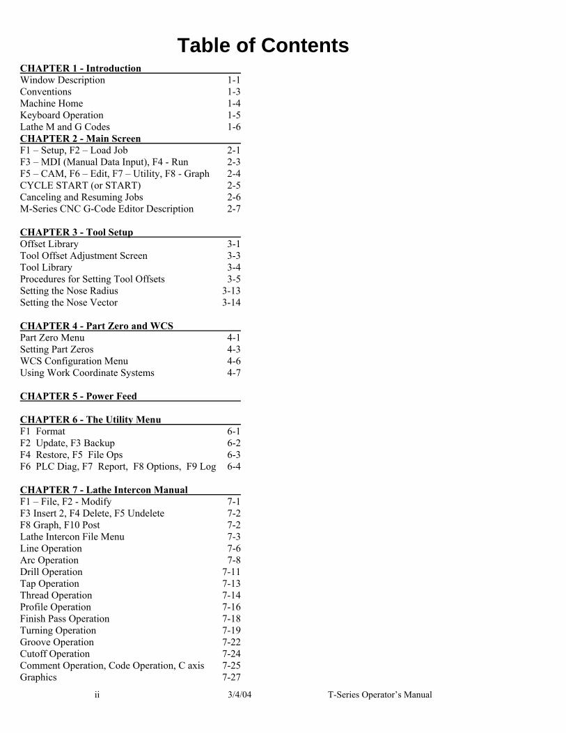
Table of Contents CHAPTER 1 - Introduction Window Description 1-1 Conventions 1-3 Machine Home 1-4 Keyboard Operation 1-5 Lathe M and G Codes 1-6 CHAPTER 2 - Main Screen F1 – Setup, F2 – Load Job 2-1 F3 – MDI (Manual Data Input), F4 - Run 2-3 F5 – CAM, F6 – Edit, F7 – Utility, F8 - Graph 2-4 CYCLE START (or START) 2-5 Canceling and Resuming Jobs 2-6 M-Series CNC G-Code Editor Description 2-7 CHAPTER 3 - Tool Setup Offset Library 3-1 Tool Offset Adjustment Screen 3-3 Tool Library 3-4 Procedures for Setting Tool Offsets 3-5 Setting the Nose Radius 3-13 Setting the Nose Vector 3-14 CHAPTER 4 - Part Zero and WCS Part Zero Menu 4-1 Setting Part Zeros 4-3 WCS Configuration Menu 4-6 Using Work Coordinate Systems 4-7 CHAPTER 5 - Power Feed CHAPTER 6 - The Utility Menu F1 Format 6-1 F2 Update, F3 Backup 6-2 F4 Restore, F5 File Ops 6-3 F6 PLC Diag, F7 Report, F8 Options, F9 Log 6-4 CHAPTER 7 - Lathe Intercon Manual F1 – File, F2 - Modify 7-1 F3 Insert 2, F4 Delete, F5 Undelete 7-2 F8 Graph, F10 Post 7-2 Lathe Intercon File Menu 7-3 Line Operation 7-6 Arc Operation 7-8 Drill Operation 7-11 Tap Operation 7-13 Thread Operation 7-14 Profile Operation 7-16 Finish Pass Operation 7-18 Turning Operation 7-19 Groove Operation 7-22 Cutoff Operation 7-24 Comment Operation, Code Operation, C axis 7-25 Graphics 7-27

T-Series Operator’s Manual 3/4/04 iii
Math Help 7-28 Intercon Lathe Tool Library 7-36 CHAPTER 8 - Lathe Intercon Tutorials Lathe Intercon Tutorial #1 8-1 Lathe Intercon Tutorial #2 8-8 CHAPTER 9 - CNC Program Codes E, F, N, O, P 9-1 Q, R, S, T, U, W 9-2 :, ;, Numerical Expressions 9-3 User and System Variables 9-4 Hot Keys 9-5 CHAPTER 10 - G Codes G00, G01, G02, G03 10-2 G04, G10, G20, G21, G28 10-4 G29, G30, G32 10-5 G40, G41, G42 10-6 Imaginary Tool Nose 10-7 G50, G52, G53 10-9 G54 - G59, G65 10-10 G70, G71, G72 10-12 G74 10-19 G75 10-21 G76 10-23 G80,G83, G84,G85 10-24 G90 10-25 G92 10-26 G94, G96 & G97, G98, G99 10-28 CHAPTER 11 - M-functions Macro M-functions, M00, M01 11-1 M02, M03, M04, M05, M07, M08, M09, M10 11-2 M11, M26, M29, M50, M51 11-3 M91, M92, M93 11-4 M94/M95, M98 11-5 M99, M100, M101, M102, M103 11-6 M104, M105, M106, M107, M108 11-7 M109, M115/M116/M125/M126 11-8 M120, M121, M122, M123 11-9 CHAPTER 12 - CNC Program Example CHAPTER 13 - The Operator Panel The Operator Panel 14-1 Keyboard Jog Panel 14-5 CHAPTER 14 - Configuration Password 14-1 Control Configuration 14-2 Machine Configuration 14-4 Machine Parameters 14-7 PID Configuration 14-16 CHAPTER 15 - CNC7 messages

iv 3/4/04 T-Series Operator’s Manual
T-Series Information Sheet Customer___________________ Kit #__________ Motor Type_____________ Table 1: Jog parameters Axis Slow Jog
(inches/minute) Fast Jog (inches/minute)
Max Rate (inches/minute)
Dead Start (inches/minute)
Delta Vmax (inches/minute)
Z X
Table 2: Motor parameters Axis Label Motor
revs/ inch
Encoder counts/ inch
Lash Limit+
Limit-
Home+
Home-
Direction reversed
Laser Comp
1 2
Table 3: PID parameters
Axis Kp Ki Kd Limit Kg Kv1 Ka Accel Z X
Software Information Software Version ___________ Other On-Line Software _____________ Version: _________ MasterCam SIM serial number __________________ MasterCam Level ____ PLC Program name:___________.SRC PLC Type:___________ System Voltages Source ______ VAC Cap ______ VDC 24V ______ VAC Machine Parameters (31-34) 31 ________ 32 ________ 33 ________ 34 ________

T-Series Operator’s Manual 3/4/04 1-1
CHAPTER 1 Introduction
Window Description The T-Series display screen is separated into five areas: DRO display The DRO display contains the digital readout of the current position of the tool. The display is configurable for number of axes and desired display units of measure (see Chapter 14). The bars under each axis are the load meters and represent the amount of power being supplied to the drive for that axis. The display of axis load meters is configured by machine parameter 143 – see Chapter 14 for specific information. The symbol next to the X axis DRO indicates diameter or radius mode. See also “Hot Keys” later in this chapter. Distance to Go DRO The distance to go DRO is located below the main DRO. This display shows the distance to go to complete the current movement. The display of distance to go is controlled by parameter 143. See Chapter 14 for details. See also “Hot Keys” later in this chapter. Status window The first line in the status window contains the name of the currently loaded job file (see Chapter 2). Below the job name are the Tool Offset and Tool Number, Program Number, Feedrate Override, Spindle Speed, and Feed Hold indicators. The Feedrate Override indicator displays the current override percentage set on the Jog Panel. If your machine is equipped with a variable frequency spindle drive (inverter), the Spindle indicator will display the current spindle speed. The Feed Hold indicator displays the current status of the FEED HOLD button located on the Jog Panel. If FEED HOLD is on, then the Feed Hold indicator will indicate 'On'.
DRO Display Status Window
Message Window
User Window
Function Key Options

1-2 3/4/04 T-Series Operator’s Manual
The Part Count and Elapsed Time indicators are not always displayed. Pressing CYCLE START while a job is running will cause the indicators to appear. The Part Count indicator displays the number of times the currently loaded part has been run. Upon the completion of each run, it increments by one. If a job is canceled prematurely, the Part Count will not be incremented. The Part # counter shows the how many parts have been run, with an up/down arrow displayed to indicate the counting direction. See the run menu for more information on the Part Cnt and Part# setting. The Part Time indicator displays the amount of time passed since CYCLE START was pressed. The indicator will help you to determine how long it takes to cut a particular part. The timer will not stop until the job is canceled for any reason. It will continue to count for optional stops, tool changes, FEED HOLD, etc. Message window The message window is divided into a message section and a prompt section. The prompt section is the lowest text line in the window and will display prompts to the user. For example, the prompt 'Press CYCLE START to start job' is displayed on the prompt line after power up. The message section is the top four text lines of the message window. This section will display warnings, errors, or status messages. The newest messages always appear on the lowest of the four lines. Old messages are shifted up until they disappear off the top of the message window. See Chapter 15 for a description of the T-Series error and status messages. Function Key Options Options are selected by pressing the function key indicated in the box. For example, on the Main Screen, pressing the function key F5 selects the CAM option. User window The information contained in this window is dependent on the operation you are performing on the control. Enter the part zeros and the tool library setup information in this window. The window is empty if you are performing no action. For example, when the CYCLE START button is pressed and a job is processed correctly, up to 11 lines of G code will be displayed in this window.

T-Series Operator’s Manual 3/4/04 1-3
Conventions ● There are 10 function keys used by the control. They are represented by F1, F2,… F10. Keystrokes other than the function keys are represented by enclosing the capitalized name of the key in “<” and “>” symbols. For example, the A key is written as <A> and the “Enter” key is written as <ENTER>. The "Escape" key is written as <ESC>. Key combinations such as <ALT- D> mean that you should press and hold <ALT> then press <D>. ● Data entry menus on the T-Series Control usually use F10 to save changes and <ESC> to discard changes. ● Any menu in the T-Series Control can be exited by pressing <ESC>. This will take you back to the previous menu. This also usually discards any changes you have made in that menu. ● The Centerline of the part (and Spindle) is usually considered to be where X=0. ● The orientation of the axes are as follows: X+ always points away from the Centerline and Z+ always points to the right and away from the Spindle. Although the T-Series Control is able to display the X+ direction as either oriented up or down (set in Machine Parameter 1), most of the illustrations in this manual will show X+ as appearing to point upward, as if the tool turret is mounted behind the centerline of the spindle. ● Tools move in X and Z directions. The work piece remains in a stationary location relative to X and Z. ● CW stands for clockwise, and CCW stands for counterclockwise. ● The work piece physically spins in the Spindle Chuck, the CW and CCW directions refer to the chuck spinning in those directions when viewed in the Z- direction. (From the tailstock to the spindle). ● ID means Inner Diameter, and OD means Outer Diameter.
Spindle Chuck Tool turret mounted
in front of centerline
Tool turret mounted behind centerline
Centerline (X = 0)
Z+
X+
Z+
X+

1-4 3/4/04 T-Series Operator’s Manual
Machine Home When the T-series control is first started, the Main Screen will appear as below.
Before you can run any jobs, you must set the machine home position. If your machine has home/limit switches, reference marks or safe hard stops, the control can automatically home itself. If your machine has reference marks, jog the machine until the reference marks are lined up, (see below), before you press CYCLE START to begin the automatic homing sequence. The control will execute the G-codes in a file called CNC7.HOM in the C:\CNC7T directory. By default, this file contains commands to home X to its plus limit and home Z to its plus limit.
Typical Reference Marks If your machine does not have home/limit switches or safe hard stops, the following message will appear instead.
In this case you must move the machine to its home position yourself, using either the jog keys or the handwheels. Once all axes are at their home positions, press CYCLE START to set machine home.
T-Series Operator’s Manual 3/4/04 1-5
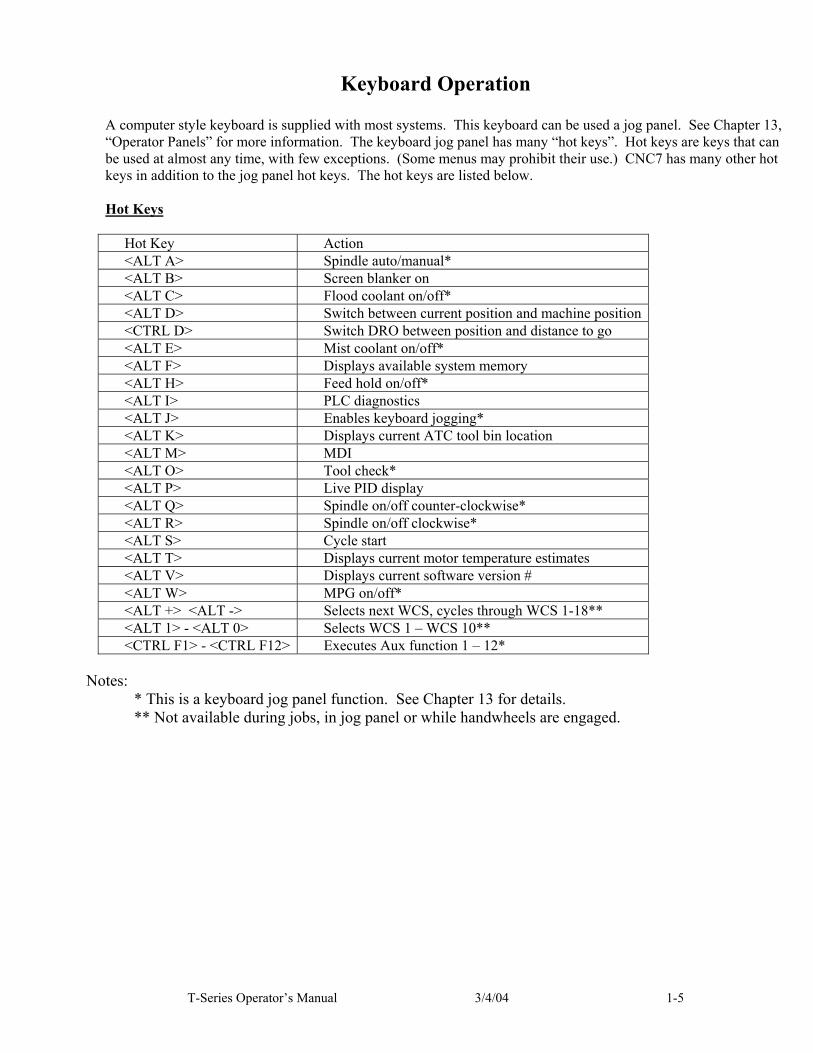
Keyboard Operation A computer style keyboard is supplied with most systems. This keyboard can be used a jog panel. See Chapter 13, “Operator Panels” for more information. The keyboard jog panel has many “hot keys”. Hot keys are keys that can be used at almost any time, with few exceptions. (Some menus may prohibit their use.) CNC7 has many other hot keys in addition to the jog panel hot keys. The hot keys are listed below. Hot Keys
Hot Key Action <ALT A> Spindle auto/manual* <ALT B> Screen blanker on <ALT C> Flood coolant on/off* <ALT D> Switch between current position and machine position <CTRL D> Switch DRO between position and distance to go <ALT E> Mist coolant on/off* <ALT F> Displays available system memory <ALT H> Feed hold on/off* <ALT I> PLC diagnostics <ALT J> Enables keyboard jogging* <ALT K> Displays current ATC tool bin location <ALT M> MDI <ALT O> Tool check* <ALT P> Live PID display <ALT Q> Spindle on/off counter-clockwise* <ALT R> Spindle on/off clockwise* <ALT S> Cycle start <ALT T> Displays current motor temperature estimates <ALT V> Displays current software version # <ALT W> MPG on/off* <ALT +> <ALT -> Selects next WCS, cycles through WCS 1-18** <ALT 1> - <ALT 0> Selects WCS 1 – WCS 10** <CTRL F1> - <CTRL F12> Executes Aux function 1 – 12*
Notes:
* This is a keyboard jog panel function. See Chapter 13 for details. ** Not available during jobs, in jog panel or while handwheels are engaged.

1-6 3/4/04 T-Series Operator’s Manual
Lathe M and G Codes
M00 Stop for operator M01 Optional Stop for operator M02 Restart Program M03 Spindle on CW M04 Spindle on CCW M05 Spindle off M07 Mist Coolant on M08 Flood Coolant on M09 Coolant off M10 Clamp on M11 Clamp off M13 Cutoff M18 Home turret M22 Extend part chute M23 Retract part chute M29 Set trap for G84 M41 Select spindle #1 M42 Select spindle #2 M50 C-axis Disable M51 C-axis Enable M91 Move to minus home M92 Move to plus home M93 Release motor power M94 Turn on input X M95 Turn off input X M98 Call subprogram M99 Return from subprogram M100 Wait for input to open M101 Wait for input to close M102 Restart program M103 Programmed action timer M104 Cancel programmed action timer M105 Move minus to switch M106 Move plus to switch M107 Output BCD tool number M108 Enable override controls M109 Disable override controls M115 Protected probing move M116 Protected probing move M120 Open data file (overwrite existing file) M121 Open data file (append to existing file) M122 Record position(s) and/or comment in data field M123 Record value and/or comment in data field M125 Protected probing move M126 Protected probing move
G00 Rapid Positioning G01 Linear Interpolation G02 Circular or Helical Interpolation CW G03 Circular or Helical Interpolation CCW G04 Dwell G10 Parameter Setting G20 Select Inch Units G21 Select Metric Units G28 Return to Reference Point G29 Return from Reference Point G30 Return to Secondary Reference Point G32 Constant Lead Thread Cutting G40 Cutter Diameter Compensation Cancel G41 Cutter Diameter Compensation Left G42 Cutter Diameter Compensation Right G50 Coordinate System Setting, Max. Spindle Speed
Setting G52 Offset Local Coordinate System G53 Rapid Position in Machine Coordinates G54 Select Work Coordinate System #1 G55 Select Work Coordinate System #2 G56 Select Work Coordinate System #3 G57 Select Work Coordinate System #4 G58 Select Work Coordinate System #5 G59 Select Work Coordinate System #6 G65 Call Macro G70 Finishing Cycle G71 Stock Removal in Turning G72 Stock Removal in Facing G74 End Face Peck Cutting G75 Outer/Inner Diameter Peck Cutting Cycle G76 Multi-Pass Threading Cycle G80 Cancel Canned Cycle G83 Deep Hole Drilling G84 Tapping (Optional) G85 Boring Cycle G90 Outer/Inner Diameter Cutting Cycle G92 One-Pass Threading Cycle G94 End Face Cutting Cycle G96 Constant Surface Speed G97 Constant Surface Speed Cancel G98 Per Minute Feed G99 Per Revolution Feed

T-Series Operator’s Manual 3/4/04 2-1
CHAPTER 2 Main Screen
When the T-Series control is started, the first menu to appear is the Main Screen.
F1 - Setup When you press F1 from the Main Screen, you will be shown the Setup menu containing options related to setting up various aspects of the machine. These options are explained in detail in the next three Chapters.
F2 – Load Job Pressing F2 from the Main Screen allows you to specify the file name of the CNC program that you want to run next. The Load Job Screen is shown as follows.

2-2 3/4/04 T-Series Operator’s Manual
When the Load Job Screen is first displayed, the initial list of files will come from the Control’s hard drive. You can press F1 to switch to the control's floppy drive or press F3 to switch to the drive of a computer attached via a network or null modem cable. Press F2 to switch back to the control's hard drive. You can use the arrow keys to move the cursor to the file you want to load. Once the job file name you wish to load is displayed on the "Job to load" line, press F10. If you wish to use the Remote feature with a null modem cable you should run the INTERSVR program supplied with MS-DOS on the remotely attached computer. See Remote Drive and Directory in Chapter 14 if you need to set up a default drive and directory for the remote feature. On the Load Job Screen, the available keys are:
F1 change to the Floppy drive (A:\ directory) F2 change to the Hard Drive (C:\CNC7T\NCFILES directory) F3 change to an attached computer's drive via RS232 port or network connection F10 load the selected file <Page Up> move the cursor back one page. (A page is 32 files) <Page Down> move the cursor forward one page. <END> select the last file in the list. <HOME> select the first file in the list. Arrow Keys move the cursor in the selected direction
Subdirectories are shown at the end of the list with square brackets, "[" and "]", around the name. If the current directory is not the root directory, a parent directory reference is shown as the last item of the list, signified by an up arrow next to the name. If you know the name of the file you wish to load, type the name on the keyboard and press <ENTER>. When you begin to type, the cursor will move down to the "Job to load" line and display what you have typed on the keyboard. Once <ENTER> is pressed, the control will attempt to find the file. If the file is found, it will be loaded into the control as the selected Job Name. If the file is not located in the current directory, you can type the entire path. Advanced users: The "Job to load" line can perform functions similar to the DOS commands DIR and CD. See the examples below:
If you type: The menu will *.CNC display all files in the current directory that have a .CNC
extension F*. * display all files in the current directory that begin with F .. move up one directory and display all files located in that
directory A: change to the last selected directory on the A: floppy drive
and display all files located in that directory \ change to the root directory of the current drive and
display all the files located in that directory C:\ICN_LATH change to the C:\ICN_LATH directory and display all the
files located in that directory A:\G*.CNC change to the A: floppy drive root directory and display all
files beginning with G that have a CNC extension TEST?.CNC display all files beginning with TEST that have one more
character (TESTA, TEST1, etc.) and have the CNC extension

T-Series Operator’s Manual 3/4/04 2-3
extension
Using this ability is similar to using DIR and CD in DOS but leaving off the DIR or CD. If you can only remember part of the file name or it is located in another directory, these commands make it easier to locate. (See the DIR and CD commands in your MS-DOS manual for further information). WARNING: DO NOT load non G-code files and attempt to run or edit them. The operation of the Graph feature is explained in the “F8- Graph” section later in this chapter.
F3 – MDI (Manual Data Input) Pressing F3 from the Main Screen will allow you to directly enter M and G-codes one line at a time from the keyboard. After pressing CYCLE START, the Control will immediately execute the command you typed. It will then prompt you for another line. When you are finished entering commands, press <ESC>. Examples:
Block? G50X0Z0 ; Set the current XZ position to 0,0 Block? M26/Z ; Set the current Z position as Z home
F4 - Run Press F4 from the Main Screen to change the way your part program will run. You can select an alternate starting point, turn single block mode on or off, and turn optional stops on or off. The options on the Run menu are: F1 - Resume Job The Resume Job feature allows you to resume a previously canceled job at or near the point of interruption. See the section titled "Canceling and Resuming Jobs" in this chapter for a further detailed explanation. F2 - Search Invoking this option will bring you to the “Search and Run” menu. This menu will allow you to specify the program line, block number, or tool number at which execution of a program is to begin. Program lines are numbered from the top of the file down with the first line numbered 1. To enter a block number place an "N" in front of the number. To enter a tool number place a "T" in front of the number. Pressing CYCLE START from here would start the program at the point you specified. An extra option unique to the “Search and Run” menu is the F1 “Do Last Tool Change” function. This key toggles the tool change option as shown on menu. A "YES" tells the control to perform a tool change so that the tool specified for the line or block has the tool indicated in the program. A "NO" uses the currently loaded tool, regardless of what tool is specified for the line or block being searched. F3 – Repeat On/Off This key toggles the repeat feature for part counting. When part counting is in effect and Repeat in on, the job will be automatically run again until the specified number of parts have been run. The On or Off label indicates the state to which the repeat feature will toggle to when pressed. It does not indicate the current state. The current state is indicated in the user window above. The Part Count: prompt is used to set the Part count. Positive values set the part counter to count up and negative values configure the part count to count down. For example, if 10 is entered in the Part Count prompt, the Part Cnt in the status window changes to 10 and the Part # changes to 0 with an upward arrow indicator. When a job is run and then completes, the Part# will increment to 1. If repeat is on, the job will automatically start again and keep running until the Part # has reached the Part Cnt. If a –10 is entered in the Part Count prompt, the Part Cnt in the status window changes to 10 and the Part# changes to 10 with a downward arrow indicator. When a job completes, the Part # will decremented to 9. If repeat is on, the job will automatically start again and keep running until the Part# has reached 0.

2-4 3/4/04 T-Series Operator’s Manual
F4 - /Skips On/Off This function toggles the block skip feature. When block skipping is on, G-code lines that start with a forward slash character ‘/’ are skipped, i.e., they are not processed. The On or Off label indicates the state to which the /Skips feature will toggle to when pressed. It does not indicate the current state. The current state is indicated in the user window above. F5 - Block Mode Turns single block mode on and off. This is similar to pressing AUTO/BLOCK. If single block mode is on, CNC7 will stop after each block in your part program and wait for you to press CYCLE START. F6 - Optional Stops Turns optional stops on and off. If optional stops are on, any M1 codes that appear in your program will cause a wait for CYCLE START (just like M0). If optional stops are off, M1 codes will be ignored. F8 - Graph Graphs the part. For more information, see the F8 – Graph section as described later. If this feature is invoked from the Run and Search menu or the Resume Job menu, then the graphics will show exactly where the searched line or block begins. Dotted lines indicate the portion of the part that is skipped. Solid lines indicate the portion of the part that will be machined. F9 – Rapid On/Off This function key toggles Rapid Override. The On or Off label indicates the state to which the Rapid Override feature will toggle to when pressed. It does not indicate the current state. It has the same effect as the Rapid Over key discussed in Chapter 13. F10 – RTG On/Off This function key toggles the Run-Time Graphics option. If the option is turned on, Run-Time Graphics automatically starts when the CYCLE START button is pressed. This option must be turned on for Run-Time Graphics to be used. If the option is turned off, Run-Time Graphics cannot be started while a job is running.
F5 - CAM Choose F5 from the Main Screen to load an installed CAM software package. Currently, the default CAM system is Intercon (Interactive Conversational) for Lathe software. Your dealer can install other CAD/CAM packages. If more than one CAD/CAM program or on line software package has been installed, a menu will appear that allows you to choose the appropriate program. When you exit the CAD/CAM software, you will return to the T-Series Control Main Screen.
F6 - Edit The edit function from the Main Screen loads a text editor so that you may edit CNC files. Pressing F6 will load the current job file automatically, as indicated by the Job Name displayed in the status window. When you exit the text editor software, you will return to the CNC7 Main Screen. WARNING: Attempting to edit files that contain non-printable characters may cause unexpected results. DO NOT edit the CNC7 files CNC7.CFG, CNC7.PRM, CNC7.JOB, CNC7.TTL and CNC7.WCS. These files will be destroyed and all information lost if they are edited.
F7 - Utility Pressing F7 will bring up the Utility Menu. This menu gives you several options from diagnostics to file functions. See Chapter 6 for a detailed description of the utility operations.
F8 - Graph In addition to the Main Screen, the Graph feature can be accessed from other menus like the Load Job Screen and the various Run Job menus. Use the Graph feature to show a tool path of the current program loaded. The following is a sample graph of a part:

T-Series Operator’s Manual 3/4/04 2-5
A wire frame tool path of your part should appear. Each axis is indicated by the X or Z marker, along with scales to indicate the current location of the part. Here is a list and the function of the F-Keys located on the bottom of the screen: F3 - Set Range Press this key to set the range of line numbers or block numbers to graph. F4 - Time Estimation Press this key to estimate the time needed to create the part. It takes into account accelerations and decelerations, but neglects tool change times. F5 - Redraw Press this key to redraw the graphics at any time. F6 - Pan Press this key to move the part around the graph. Once pressed, use the crosshatches to pick a location of the part that will pan to the center of the graph. Once a section is selected, press F6 again to continue panning. F7 - Zoom In Press this key to zoom into the part relative to the center of the graph. F8 - Zoom Out Press this key to zoom away from the part relative to the center of the graph. F9 - Zoom All Press this key to view the entire part fit inside the graph.
F10 – Park Press <F10> to park the machine at the end of the day for quicker machine homing at startup. Once <F10> is selected, the Cycle Start key must be pressed to start machine movement. The park feature moves each axis, at the max. rate, to ¼ motor revolution from its home position. The Z axis is moved first, then all other axis next.

2-6 3/4/04 T-Series Operator’s Manual
CYCLE START (or START) Press this key to run a job from this screen. See Chapter 13 for a description of the CYCLE START button.
ALT-S The <ALT-S> option is for those operators who have no Jog Panel. Pressing <ALT-S> is the same as pressing the CYCLE START button on the operator panel.
Canceling and Resuming Jobs The control provides several ways for the operator to cancel jobs in progress. The control also allows the operator several ways to resume a canceled job.
Canceling a Job in Progress There are three conventional ways to cancel a currently running job (CNC program). When a job is canceled using any of the following methods, the job's progress will be recorded. This allows the user to restart the job using the Resume Job option or the Search and Run option. CYCLE CANCEL Pressing this key while a job is running will cause the control to abort the job currently being run. The control will stop movement immediately, clear all M-functions, and return to the main screen. TOOL CHECK This has the same effect as CYCLE CANCEL except that a smoother deceleration will take place before the control stops motion. Once the spindle stops, the control will allow you to manually clear the tool of any obstacles, such as being inside of a bore, then depress tool check a second time to return the tool to the tool check position. Emergency Stop Pressing the Emergency Stop key while a job is running will cause the control to abort the job currently being run. The control will stop movement immediately, clear all M-functions, and return to the main screen. Also, the power to all axes will be released.
Resuming a Canceled Job If a job is canceled using one of the methods described above, it can be resumed in one of 2 ways. Resume Job Screen – F1 from the Run Screen Access the resume job screen by pressing F4 on the main screen to go to the run screen, and then pressing F1 in the run screen to go to the resume job screen. If the job was canceled by pressing Tool Check, the control will go to the resume job screen automatically. From this screen, the user can modify tool offsets and the tool library, turn block mode on and off, turn optional stops on or off, graph the partially completed job, or start the partially completed job. The resume job option is not always available. The following situations will cause the resume job option to be unavailable: ● Loading a new job. ● Running a job to completion. ● Parse errors in the job. ● Editing or reposting the job file. ● Loss of power while running a job. Search and Run Screen – F2 from the Run Screen The search and run screen can also be used to restart a job. Search and run allows the user to specify at which line, block, or tool number the job should be resumed.

T-Series Operator’s Manual 3/4/04 2-7
T-Series CNC G-Code Editor Description This is a detailed description of the F6[Edit] option invoked from the Main screen.
Usage To edit a G-code program, press F6[Edit] from the main screen. The G-code of the current job will be loaded. NOTE: If the editor is invoked from the DOS command line, a file may be loaded into the editor by either specifying a name on the command line, or by entering the editor and selecting the F9[Load File] option. Examples:
C:\CNC7T\NCFILES>cnc7edt Invoking editor from command line C:\CNC7T\NCFILES>cnc7edt cnc40.cnc Invoking editor and loading a file from the command line.
Editor Screen The editing screen will have a status line across the top of the screen, while the bottom line of the screen will show some of the available editor functions. The status line displays the current cursor line and column, the current typing mode (Insert/Overwrite), a "modified" message if the file has been modified since the last time is was saved, and the name of file currently being edited. Below is a sample editing screen:
Pressing the F1 key will display a complete list of editor functions and the key(s) that activate them. Press any key to return to editor screen.
Editor Functions The following table contains a list of all available editor functions, the keys that activate them, and brief descriptions of their effects:
Editor function Key(s) Comments Insert/Type over mode Move cursor left, right, up, downMove cursor to beginning of lineMove cursor to end of line Scroll up one screen Scroll down one screen
Insert Arrows Home End Page Up Page Down
Type over cursor is an underline; insert cursor is a block.

2-8 3/4/04 T-Series Operator’s Manual
Move to beginning of file Move to end of file
Ctrl + Page Up Ctrl + Page Down
Delete character under cursor Delete character in front of cursor Delete current line
Del Backspace Ctrl + Y
Deleting at end of line joins with next line. Deleting at beginning of line joins to preceding line.
Help F1 Displays list of all editor commands. Pressing any key returns to the editor.
Load file Save file Exit
F9 F2 F10
Load a file for editing. If a file name is specified for a file that does not exist, a new file will be created. See user dialog table below. Save current file to disk. See user dialog table below. Quit using editor. See user dialog table below.
Search forward Search forward again Replace
F3 F4 F5
Specify string to search for; this is a case-sensitive search Replace all occurrences of one text string with another string. See user dialog table below.
Escape Esc Cancel current dialog sequence. Table 1 - Editor Function Descriptions
The table below describes the dialog sequences involved in using editor functions:
Function Condition Question Save file A file with the current name already
exists. You answer N to the "replace" question. You choose a file name that already exists.
"Do you want to replace the original file <current file name>? Y/N" "Specify a new file name" "Do you want to replace the original file <selected file name?> Y/N"
Load file You have made changes to the current file and have not saved them. You answer Y to the "save" question. You answer N to the "save" question, or you complete the above save process.
"Do you want to save changes in the file <current file name>? Y/N"Perform the save file process above. "Specify file name to be loaded"
Exit editor You have made changes to the current file and have not saved them. You answer Y to the "save" question.
"Do you want to save changes in the file <current file name>? Y/N"Perform the save file process above.
Replace text
The file is modified in memory and on disk.
"Pattern" (string to search for) "Replacement" (string to substitute) Perform the save file process above.
Table 2 – Dialogue Messages

T-Series Operator’s Manual 3/4/04 3-1
CHAPTER 3 Tool Setup
Four menus are involved in tool setup: ● Offset Library – specifies offset definitions to be associated with each tool ● Tool Offset Adjustment Screen – allows operator to make tool wear adjustments for each tool ● Tool Library – miscellaneous tool offset specifications ● Lathe Intercon’s Tool Library – Lathe Intercon’s version of the Tool and Offset Libraries Only the first three menus will be discussed in this chapter. See Chapter 7 for a description of Lathe Intercon’s Tool Library. For information on setting up tool offsets see the section “Procedures for Setting Tool Offsets” later in this chapter.
Offset Library To get to the Offset Library from the Main Screen, press F1[Setup] F2[Tool] F1[Offsets]. On this screen, you can define the offsets to be associated with each tool.
Elements of the Offset Library and its fields are described below: Tool: This is the offset number. Although this number is appended to a “T”, this is not a tool number. However, if you only associate tool numbers with the same numbered offset, then this field would correspond to the tool number. This field is just a display label and cannot be modified. Offset X: This field defines the X offset distance away from the tool measurement radius or diameter. (See X Diam/Radius as described below.) Offset Z: This field defines the Z offset distance away from the Z reference position. (See Z Ref as described below.) Nose Radius: This field tells the control the distance to adjust when cutter diameter compensation (G41 or G42) is activated. Nose Vector: This field tells the control how the tool is oriented in the machine. See the section titled “Setting the Nose Vector” later in this chapter for a more in-depth explanation.

3-2 3/4/04 T-Series Operator’s Manual
X Diam/Radius: This field defines the diameter or radius from which the X offsets of tools are to be measured. This diameter is usually created by a skim cut as part of the tool measuring procedure. (See the Procedures for Setting Tool Offsets section later in this chapter.) To change this field, cursor over to the Offset X column and press F1 and follow the instructions. Z Ref: This field is the Z reference position from which the Z offsets of tools are to be measured. To change this field, cursor over to the Offset Z column and press F1 and follow the instructions. Entry Mode: You can toggle between absolute input or incremental input using the F4[Abs/Inc] key. The Entry Mode affects values entered in the Offset X, Offset Z, Nose Radius, X Diam/Radius, and Z Ref fields. If the Entry Mode is Incremental, then the value that you enter will be added to currently affected field. If the Entry Mode is Absolute, then the value that you enter will change the field to that value. F1 – X Diam/Rad or Z Ref Press this key to establish the X Radius or Diameter for Tool measurement or to establish the Z reference. To establish the X Radius or Diameter, cursor over to the Offset X column and press this key and then follow the instructions. To establish the Z reference, cursor over to the Offset Z column and press this key and then follow the instructions. F2 – Measure Press this key to make a offset measurement of a tool. This key is used in the part tool measuring procedure. (See the Procedures for Setting Tool Offsets section later in this chapter.) F4 – Abs/Inc This toggles the Entry Mode between Absolute and Incremental. (See “Entry Mode” as described above.) F5 – Increment by small amount To make small incremental adjustments to an Offset X, Offset Z, or Nose Radius value, use the arrow keys to select the value to be adjusted and press this key. A small amount (as defined in Machine Parameter 70) will be added to the affected field. F6 – Decrement by small amount To make small decremental adjustments to an Offset X, Offset Z, or Nose Radius value, use the arrow keys to select the value to be adjusted and press this key. A small amount (as defined in Machine Parameter 70) will be subtracted from the affected field. F7 – ATC (Automatic Tool Change) If you have an automatic tool changer installed, you can press this key to change tools. F10 – Save Changes When you are done with modifications press this key to save the changes.
T-Series Operator’s Manual 3/4/04 3-3
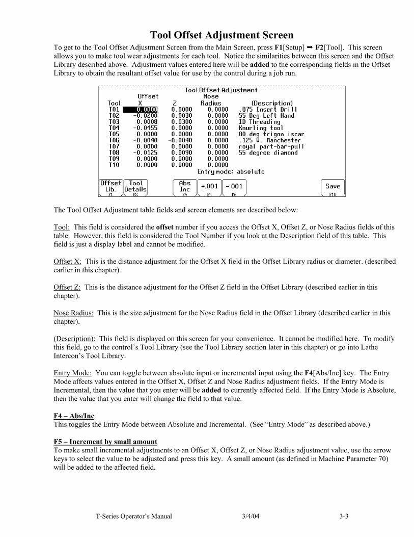
Tool Offset Adjustment Screen To get to the Tool Offset Adjustment Screen from the Main Screen, press F1[Setup] F2[Tool]. This screen allows you to make tool wear adjustments for each tool. Notice the similarities between this screen and the Offset Library described above. Adjustment values entered here will be added to the corresponding fields in the Offset Library to obtain the resultant offset value for use by the control during a job run.
The Tool Offset Adjustment table fields and screen elements are described below: Tool: This field is considered the offset number if you access the Offset X, Offset Z, or Nose Radius fields of this table. However, this field is considered the Tool Number if you look at the Description field of this table. This field is just a display label and cannot be modified. Offset X: This is the distance adjustment for the Offset X field in the Offset Library radius or diameter. (described earlier in this chapter). Offset Z: This is the distance adjustment for the Offset Z field in the Offset Library (described earlier in this chapter). Nose Radius: This is the size adjustment for the Nose Radius field in the Offset Library (described earlier in this chapter). (Description): This field is displayed on this screen for your convenience. It cannot be modified here. To modify this field, go to the control’s Tool Library (see the Tool Library section later in this chapter) or go into Lathe Intercon’s Tool Library. Entry Mode: You can toggle between absolute input or incremental input using the F4[Abs/Inc] key. The Entry Mode affects values entered in the Offset X, Offset Z and Nose Radius adjustment fields. If the Entry Mode is Incremental, then the value that you enter will be added to currently affected field. If the Entry Mode is Absolute, then the value that you enter will change the field to that value. F4 – Abs/Inc This toggles the Entry Mode between Absolute and Incremental. (See “Entry Mode” as described above.) F5 – Increment by small amount To make small incremental adjustments to an Offset X, Offset Z, or Nose Radius adjustment value, use the arrow keys to select the value to be adjusted and press this key. A small amount (as defined in Machine Parameter 70) will be added to the affected field.

3-4 3/4/04 T-Series Operator’s Manual
F6 – Decrement by small amount To make small decremental adjustments to an Offset X, Offset Z, or Nose Radius adjustment value, use the arrow keys to select the value to be adjusted and press this key. A small amount (as defined in Machine Parameter 70) will be subtracted from the affected field. F7 – ATC (Automatic Tool Change) If you have an automatic tool changer installed, you can press this key to change tools. F10 – Save Changes When you are done with modifications press this key to save the changes.
Tool Details To get to the Tool Details screen from the Main Screen, press F1[Setup] F2[Tool] F2[Tool Details]. This screen allows you to view and change miscellaneous tool offset descriptions for use by Lathe Intercon.
The Tool Detail fields and screen elements are described below: Tool (Offset): This field is the tool offset number. It is selected in lathe CNC programs by the third and fourth digits of the T number. For example, T0122 selects tool offset 22 and turret station 01. For convenience in editing, you may jump directly to any offset number by entering the new number in the Tool field. Station: This field contains the station number (turret position) of the tool that uses this offset. This field corresponds to the first two digits of the T number in CNC programs and the “Tool Loc” (Tool Location) field in Lathe Intercon’s version of the Tool Library. To change the station number, type a new number and press <ENTER>. Normally, you should try to keep this number the same as the offset number. However, if you want to use 2 or 3 different offsets for one tool, this is the field that you should change. For example, T0101, T0122, T0123 specify different offsets for the same tool station position. In the tool details, you would enter “1” in the station field of offsets 1, 22, and 23. When you choose an offset from the Intercon Tool Library, Intercon automatically inserts the selected station/offset combination. When you map multiple offsets to a single tool this way, it is likely that most of the information in the respective offsets will be very similar with minor differences. Description: This field contains a text description of the tool. The description will appear in a prompt message on the screen when the control software reaches a tool change during a job run. Type: This field specifies a general class of tool. It is supplied for your reference only. CNC7 does not make use of this information. Possible values are “Turning”, “Threading”, “Grooving/Parting”, “Boring”, “Drill/Tap/Reamer”, and “Custom”. To change the value, press <SPACE> until the desired type is shown. Operation: This field specifies whether the tool is an “Outer Diameter” or “Inner Diameter” tool. CNC7 does not use this information at the present time. In future releases of CNC7, it may be necessary to set this field correctly on systems that are configured for gang tooling.

T-Series Operator’s Manual 3/4/04 3-5
Approach: This field specifies the tool approach direction for a gang tool type or dual tool turret type lathes. It is an essential input to the “most likely nose vector” calculation. To be able to change this value parameter 163 (gang tool parameter) must be set to a 1, otherwise this field should display the direction of all tool approaches as determined by parameter 1. Spindle Direction: This field specifies the spindle direction. Possible values are “CW (M3)”, “CCW (M4)”, “NSP” (no spindle) and “Off”. It is an essential input to the “most likely nose vector” calculation. Spindle Side: This field specifies whether the spindle is mounted on the left or right side of the machine. It is an essential input to the “most likely nose vector” calculation. Mount Direction: This field specifies how the tool is mounted. Possible values are “Vertical” and “Horizontal”. It is an essential input to the “most likely nose vector” calculation. Mount Reversal: This field specifies how the tool is mounted. Possible values are “Normal” and “Reversed”. It is an essential input to the “most likely nose vector” calculation. Hand of Tool: This field specifies whether the tool is left handed, right handed or neutral. The hand of tool is defined as the general direction the insert points when the tool is held flat in your hand, insert side up and facing you. It is an essential input to the “most likely nose vector” calculation. Due to the geometry of some inserts such as grooving and cutoffs, you should use the direction of cut as a guide to setting the hand rather than using the strict definition of handedness. To get the “most likely vector” to match your actual nose vector, you should choose “Neutral”. Vector: This field specifies how the tool is oriented in the machine. It is the same as the Nose Vector field in the Offset Library screen. See the section titled “Setting the Nose Vector” later in this chapter for a more in-depth explanation. To the right of the vector field are two pictures that display the most likely orientation and most likely nose vector, respectively. These pictures are chosen based on the values that you selected for Approach, Spindle Direction, Spindle Side, Mount Direction, Mount Reversal and Hand of Tool. The most likely nose vector is shown in black. The next most probable vectors are shown in red. This feature is provided as an aid to selecting the correct nose vector. It should be used as a guide and secondary check only. Never blindly set the vector based on this value. You must select the actual nose vector and enter it into the vector field. The value that you enter will most probably be exactly what is displayed as the “most likely” nose vector. If not exact, the vector that you enter will probably be a vector with a similar orientation, such as the vectors displayed in red. As discussed in “Hand of Tool”, the most likely vector for grooving and cutoffs will not match the true nose vector if the strict definition of handedness is used. Nose Radius: This field tells the control the distance to adjust when cutter diameter compensation (G41 or G42) is activated. It is the same field found in the Tool Offset library. Coolant: This field specifies a default coolant type to use with each tool. Possible values are FLOOD, MIST, or OFF. Lathe Intercon uses this information to automatically insert M7 or M8 after a tool change. To change the value, press <SPACE> until the desired value is shown. X Offset: This field defines the X offset distance away from the tool measurement radius or diameter. (See X Diameter/Radius as described below.) The field is the same as the Offset X field in the Offset Library but the automatic measurement procedure is slightly different. Either cursor over to the X Offset field or press F1 to jump directly to it. Follow the instructions. Z Offset: This field defines the Z offset distance away from the Z reference position. (See Z Ref as described below.) The field is the same as the Offset Z field in the Offset Library but the automatic measurement procedure is slightly different. Either cursor over to the Z Offset field or press F2 to jump directly to it. Follow the instructions.

3-6 3/4/04 T-Series Operator’s Manual
X Diameter/Radius: This field defines the diameter or radius from which the X offsets of tools are to be measured. This diameter is usually created by a skim cut as part of the tool measuring procedure. (See the Procedures for Setting Tool Offsets section later in this chapter.) To change this field, cursor over to the X Diameter/Radius field (or press F3) and follow the instructions. Z Ref: This field is the Z reference position from which the Z offsets of tools are to be measured. To change this field, cursor over to the Z Offset field (or press F4) and follow the instructions. Note: Instructions are displayed when you move the cursor to the X Offset, Z Offset, X Diam/Radius and Z Ref. Fields. These instructions cannot be dismissed. Use the arrow keys to move to another field. F1 – X Offset / Set X Off When the cursor is anywhere except the X Offset field, the F1 button reads “X Offset”. Press F1 in this case to jump directly to the X Offset field and display instructions. When the cursor is on the X Offset field, the F1 button changes to “Set X Off”. Press F1 in this case (per instructions) to set the current position as the X offset. F2 – Z Offset / Set Z Off When the cursor is anywhere except the Z Offset field, the F2 button reads “Z Offset”. Press F2 to jump directly to the Z Offset field and display instructions. When the cursor is on the Z Offset field, the F2 button changes to “Set Z Off”. Press F2 in this case (per instructions) to set the current position as the Z offset. F3 – X Diam/Rad Press this key to jump directly to the X Diameter/Radius field and display instructions. F4 –Z Ref / Set Z Ref When the cursor is anywhere but the Z Ref field, the F4 button reads “Z Ref”. Press F4 in this case to jump directly to the Z Ref field and display instructions. When the cursor is on the Z Ref field, the button changes to “Set Z Ref”. Press F4 in this case (per instructions) to set the current position as the Z Reference. F10 – Save Changes When you are done with modifications press this key to save the changes and return to the Offset Adjustment screen. F10 will save all changes to all offsets, not just the one currently displayed. Esc – Abandon Changes Esc will abandon edits to all offsets that you changed, not just the one currently displayed.
T-Series Operator’s Manual 3/4/04 3-7
Procedures for Setting Tool Offsets: Introduction Follow these five steps to successful CNC turning: ● Determine the tools necessary to machine the part by analyzing the print. ● Set the X and Z offsets for each tool. (This Chapter) ● Program the part using Intercon. (Chapter 7, Lathe Intercon Manual) ● Set the X and Z Part Zero positions on the stock to be machined. (Chapter 4) ● Graph the part to check for programming errors, and machine the part. Tool offsets let the control know the difference in position for each tool being used. Since different tools are at different positions, each tool will have its own specific offset value in X and Z. For a multi-tool job, it is critical that the X and Z offsets for each tool are set at the proper values. We will use the control to determine the difference in location of each tool by simply defining a position from which to measure each individual tool. The easiest method is to make a skim cut and then touch each tool off of the newly measured skim cut diameter. The control will record the distance that each tool had to move to touch off the known diameter. Once the X and Z offset information is known for each tool, a multi-tool program can be run with success. Before doing the procedures in the ensuing sections, make sure: ● The “Entry Mode” field in the Offset Library is toggled to “absolute”. ● The control is in Diameter mode (set Machine Parameter 55 to 0) ● The adjustment values in the Tool Offset Adjustment Screen (described earlier in this chapter) are all zeroed out for the tools which will be involved in the measurement process. The following instructions show how to set offsets using the Offset Library screen. You may also use the Tool Details screen to set offsets. The details of entering the offset values are different on the Tool Details screen. Otherwise, the procedures are identical.

3-8 3/4/04 T-Series Operator’s Manual
Setting X-Axis Tool Offsets for OD Tools. ● NOTE: Before you begin, the adjustment values in the Tool Offset Adjustment Screen (described earlier in this chapter) should be all zeroed out for the tools which will be involved in the steps below. STEP 1: Chuck up a piece of stock, and use the Jog buttons to make a skim cut (Figure 1). Leave the tool set at this X position. ● NOTE: Start spindle by switching to manual mode, press Spin Start button, and adjust RPM with the spindle override knob. STEP 2: Measure the new skim cut diameter, as shown in Figure 2. STEP 3: Open the Offset Library On the T-Series Control Main Screen, press: F1[Setup] F2[Tool] F1[Offset Lib.] STEP 4: Set the X Measurement Diameter Now press F1[X Diam], enter the diameter measured in Step 2 into the Establish the X Diameter field, and press F10[Save] to accept. The X-Measurement Diameter for OD tools is now set.
Figure 3
Figure 1 Figure 2
=1.8721”

T-Series Operator’s Manual 3/4/04 3-9
STEP 5: Measure the X-Offset Press F2[Meas] to measure the X-offset of the tool used to make the skim cut. The value appears in the X Offset field.
Figure 4
NOTES: ● Be sure that the cursor in the tool library is in the X offset field for the offset number that you are measuring. For instance, if you are using tool #1, make sure the cursor is in the X offset T01 position BEFORE pressing F2. ● Press F2[Meas.] while the tool is STILL at the skim cut diameter. ● Any piece of stock can be used to set tool offsets. It is not necessary to use the actual part blank. STEP 6: Measure the Next Tool Touch the next tool to the new skim cut OD (the X Measurement Diameter) as shown in Figure 5, and press F2[Meas]. Repeat this step for the rest of your OD tools. NOTES: ● Be sure you are clear of any obstacles, then use “Tool Check” to withdraw a tool from its current position. ● Use a piece of paper to touch off the next tool to the skim cut diameter. Slow jog close to the work piece, switch to Incremental jog mode and jog in close at small increments until the tool just pins the paper to the work piece. ● If you are using an ATC, be sure that you are clear of any obstacles, then use the ATC button in the Tool Library to rotate the ATC to the next tool position.
Figure 5
For each new OD tool: Touch off X diameter and press F2[measure]
3-10 3/4/04 T-Series Operator’s Manual
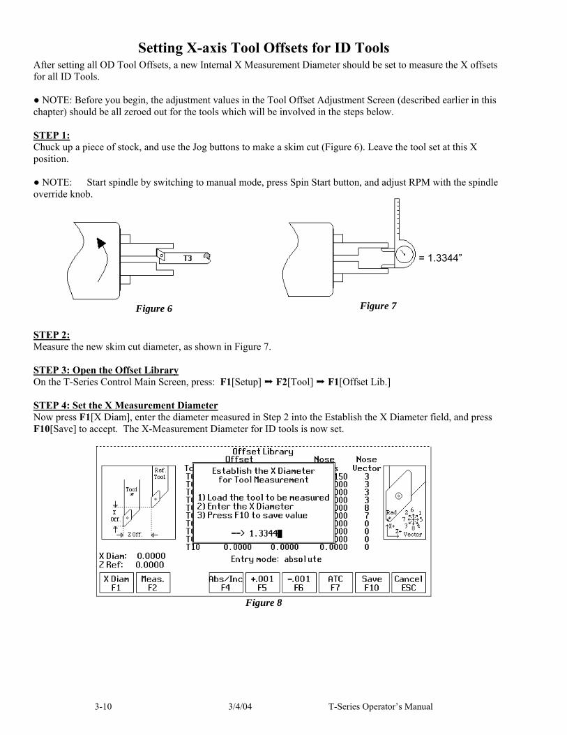
Setting X-axis Tool Offsets for ID Tools After setting all OD Tool Offsets, a new Internal X Measurement Diameter should be set to measure the X offsets for all ID Tools. ● NOTE: Before you begin, the adjustment values in the Tool Offset Adjustment Screen (described earlier in this chapter) should be all zeroed out for the tools which will be involved in the steps below. STEP 1: Chuck up a piece of stock, and use the Jog buttons to make a skim cut (Figure 6). Leave the tool set at this X position. ● NOTE: Start spindle by switching to manual mode, press Spin Start button, and adjust RPM with the spindle override knob. STEP 2: Measure the new skim cut diameter, as shown in Figure 7. STEP 3: Open the Offset Library On the T-Series Control Main Screen, press: F1[Setup] F2[Tool] F1[Offset Lib.] STEP 4: Set the X Measurement Diameter Now press F1[X Diam], enter the diameter measured in Step 2 into the Establish the X Diameter field, and press F10[Save] to accept. The X-Measurement Diameter for ID tools is now set.
Figure 8
Figure 6 Figure 7
= 1.3344”

T-Series Operator’s Manual 3/4/04 3-11
STEP 5: Measure the X-Offset Press F2[Meas.] to measure the X-offset of the tool used to make the skim cut. The value appears in the X Offset field.
Figure 9
NOTES: ● Be sure that the cursor in the tool library is in the X offset field for the offset number that you are measuring. For instance, if you are using tool #5, make sure the cursor is in the X offset T05 position BEFORE pressing F2. ● Press F2[Meas.] while the tool is STILL at the skim cut diameter. STEP 6: Measure the Next Tool Touch off all internal tools on this new internal diameter and press F2[Meas.] to measure each one. Repeat this step for all the remaining ID tools (Figure 10). NOTES: ● Be sure you are clear of any obstacles, then use “Tool Check” to withdraw a tool from it current position. ● Use a piece of paper to touch off the next tool to the skim cut diameter. Slow jog close to the work piece, switch to Incremental jog mode and jog in close at small increments until the tool just pins the paper to the work piece. ● If you are using an ATC, be sure that you are clear of any obstacles, then use the ATC button in the Tool Library to rotate the ATC to the next tool position.
Special Cases: Sometimes it might be difficult to touch a new tool off the X Measurement Diameter set in Step 2. If this is the case, you can repeat each step from Step #1 through 5 for EACH tool, reading in a new reference position for EACH tool! In this case, you will make a new skim cut Measurement Diameter for each tool and enter in that new skim cut diameter as a new reference position for that tool This method is more work, but if touching off a new tool to an existing reference position is very difficult, this method may be used for both OD & ID tools.
Figure 10
For each new ID tool: Touch off X diameter and press F2[measure].

3-12 3/4/04 T-Series Operator’s Manual
Setting X Axis Offsets for Drills, Center Drills, and Taps To set drills, center drills, taps, and boring tools, sweep the tool in with an indicator to find the spindle center. Remember that the X Measurement Diameter should be set to ‘ 0 ‘ before proceeding with step 1. (See the section “Setting X-Axis Tool Offsets for OD Tools” earlier in this chapter for directions on setting an X Measurement Diameter) ● NOTE: Before you begin, the adjustment values in the Tool Offset Adjustment Screen (described earlier in this chapter) should be all zeroed out for the tools which will be involved in the steps below. STEP 1: Set the Indicator Mount the indicator base on the spindle or put the indicator in the chuck. Move the tool towards the approximate center of the spindle. (Figure 11) STEP 2: Center the Drill Touch the indicator probe to the shank of the tool, and rotate the chuck by hand. Jog the X-axis in incremental mode until the indicator reads the same around the circumference of the tool. STEP 3: Measure the X Offset Press F2[Meas] to measure the X-offset of the tool. The value appears in the X Offset field. ● NOTE: This procedure may also be used in setting ID tool offsets in cases where an initial ID skim cut is not possible.
Setting X Axis Offsets for Boring Tools Since boring tools come with a manufactured offset, setting a boring tool is just like setting a drill, with a few added steps. Follow Steps 1 to 3 in the previous section above, and then do the following steps: ● NOTE: Before you begin, the adjustment values in the Tool Offset Adjustment Screen (described earlier in this chapter) should be all zeroed out for the tools which will be involved in the steps below. STEP 4: Find the Tool Offset Look up the tool manufacturer’s offset for the tool being measured. STEP 5: Switch to Incremental mode With the X Offset field highlighted for the tool being measured, press the F4[Abs/Inc] key until the “Entry Mode:” field on the screen reads “incremental”. STEP 6: Enter the Given Offset Multiply the manufacturer’s offset by negative two (–2), and type the number into the X Offset field. The value you type should appear as being added to the measured X offset already measured. ● NOTE: Be sure to press the F4[Abs/Inc] key to toggle the Entry Mode back to “absolute” when you are done.
Figure 11

T-Series Operator’s Manual 3/4/04 3-13
Setting Z-Axis Tool Offsets ● NOTE: Before you begin, the adjustment values in the Tool Offset Adjustment Screen (described earlier in this chapter) should be all zeroed out for the tools which will be involved in the steps below. STEP 1: Chuck up a piece of stock, and use the Jog buttons to make a skim cut (Figure 12) OR if the surface is true, touch off the end as shown in Figure 13. STEP 2: Open the Offset Library From the T-series Control Main Screen, press: F1[Setup] F2[Tool] F1[Offset Lib.] STEP 3: Set the Reference: Make sure the Z column is highlighted, then press F1[Z Ref] and press F10[Save] to accept this as the reference. STEP 4: Measure the Tool Offset Without moving the Z-position of the tool that you just used to set a reference point, press F2[Meas] to measure the Z-offset of that tool (it should result in a 0 as its offset), as seen in figure 14.
Figure 14
STEP 5: Measure the Next Tool Z-Offset Load the next tool and bring it to the reference point (as shown in Figure 13). Press F2[Meas]. Repeat for all remaining tools. ● NOTE: Be sure the cursor in the Tool Library is in the Z-Offset field for the Offset number being measured before pressing F2[Meas].
Z Reference

3-14 3/4/04 T-Series Operator’s Manual
Setting Part Off Tool Z-Offset: ● NOTE: Before you begin, the adjustment values in the Tool Offset Adjustment Screen (described earlier in this chapter) should be all zeroed out for the tools which will be involved in the setup as described below. Load the part off tool and bring it to the stock face (Figure 15). With the menu highlighted in the Z Offset column at the correct offset number, press the F2[Meas] measure key. If the part off tool is 0.125 wide and you want the back side of the tool to be set at Z-Zero, then highlight the Z column in the Offset Library at the offset of the tool being adjusted. Press the F4[Abs/Inc] key to toggle to incremental mode.
Figure 16
Type in -.125 and press ENTER. The value of -0.125 will be added to the value measured in Step 1. ● NOTE: Be sure to press the F4[Abs/Inc] key to toggle the Entry Mode back to “absolute” when you are done.
Figure 15

T-Series Operator’s Manual 3/4/04 3-15
Setting the Nose Radius On the Offset Library is the field for Nose Radius. This field tells the control the distance to adjust when cutter compensation is used (G41 or G42). For more details, see Chapter 10.
Figure 17
To edit the entries, first press the F4[Abs/Inc] until the “Entry Mode” field reads “absolute”. Move to the desired Nose Radius field using the arrow keys. Type in the nose radius of the tool, and then press the Enter key.

3-16 3/4/04 T-Series Operator’s Manual
Setting the Nose Vector Entering Nose Vectors for your tool will tell the control how that tool is oriented in the machine. This is needed for calculating cutter compensation and how the tool is retracted out from cutting cycles. First, highlight the nose vector column for the number of the tool being used. Then, enter the correct nose vector as indicated by the graphic display on the screen.
Figure 18
For +X side tooling (tools approach from the +X direction) nose vectors 3, 8, and 4 are used for OD turning and nose vectors 2, 6, and 1 are for ID boring. For machines that have both +X and –X tooling, such as gang tool lathes, -X side tooling (tools approach from the -X direction) uses nose vectors 2, 6, and 1 for OD turning and nose vectors 3, 8, and 4 are for ID boring. Nose vector 5 is used for backfacing and nose vectors 7 and 0 are used for drilling. Nose vectors 5, 7 and 0 will stay the same even if your tool post is mounted on the front or the rear of the machine.

T-Series Operator’s Manual 3/4/04 4-1
CHAPTER 4 Part Zero and WCS
Setting the Part Zeros for a part establishes a local coordinate system with its origin at the centerline of the part. In Centroid’s T-Series controls, this coordinate system considers X+ as always pointing away from the centerline and Z+ always pointing to the right and away from the spindle. In this chapter, Part Zeros will be discussed first, and then Work Coordinate Systems (abbreviated as WCS) will be discussed second. The WCS feature is simply a way to allow you to maintain multiple Part Zero positions on the same machine. There are a total of 18 Work Coordinate Systems available. A “Work Coordinate System” is synonymous with an individual “Part Zero”.
Part Zero Menu To get to the Part Zero menu from the Main Screen, F1[Setup] F1[Part].
The Part Zero menu fields and screen elements are described below: Axis: This field shows which axis the Part Zero is being set up for. When the Part Zero menu is first brought up, the Z axis will be shown. Press F8[Set X] to access the Part Zero menu for the X axis. Position: This field allows you to establish a non-zero offset between where the tool is and where you want the origin to be. On the X-axis, this is either a diameter or radius distance away from the part centerline that the tool tip is touching. ● NOTE: The part centerline is usually considered to be where the X axis position is 0.

4-2 3/4/04 T-Series Operator’s Manual
Tool Number: This field allows you to tell the control what tool offset number (see the Offset Library in Chapter 3) is being used while setting the Part Zero position. Although this number is called a “Tool Number”, this is not a tool number. However, if you only associate tool numbers with the same numbered offset, then this field would correspond to the tool number. ● NOTE: The Offset Library must be up to date before setting the Part Zeroes. Set All WCS: This field appears only if you are modifying the Part Zero for the X axis.
Press <SPACE> to toggle between “Yes” and “No”. If this field is toggled to “Yes” then this field specifies that the position that you enter will be copied to all the X axis Part positions in every Work Coordinate System. This will cause all Work Coordinate systems to have the same X axis Part Zero. This feature is a convenience, since the centerline position of a part is usually set at X=0, regardless of which WCS is currently active. If this field is toggled to “No” then only the currently selected WCS will be affected. F6 – Previous WCS This key is like the F3[Next WCS] key (see below) except that this key will cycle backward to the previous Work Coordinate System. You can use this key to cycle through all 18 WCSs. F7 – Next WCS This key will select the next Work Coordinate System to affect. If you will be using multiple coordinate systems, you must set up a new set of Part Zeros for each coordinate system. Each coordinate system represents a different Part Zero with their own X and Z axis local origins. You should set up both the X and Z axes for each fixture. You can use this key to cycle through all 18 WCSs. F8-Set X To get access to the Part Zero menu for the X axis, press F8[Set X]. Setting the X axis Part Zero is given special treatment in a sub-menu because it is not done very often (See the section titled “Setting X Axis Part Zero” later in this chapter). F9 - WCS Pressing this key will bring up the WCS Configuration menu, which will let you conveniently view and modify the first 6 Work Coordinate Systems. See the WCS Configuration Menu section for a further explanation. F10 – Set Pressing this key will cause the part position that you entered to be set.
T-Series Operator’s Manual 3/4/04 4-3
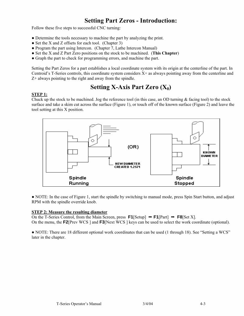
Setting Part Zeros - Introduction: Follow these five steps to successful CNC turning: ● Determine the tools necessary to machine the part by analyzing the print. ● Set the X and Z offsets for each tool. (Chapter 3) ● Program the part using Intercon. (Chapter 7, Lathe Intercon Manual) ● Set the X and Z Part Zero positions on the stock to be machined. (This Chapter) ● Graph the part to check for programming errors, and machine the part. Setting the Part Zeros for a part establishes a local coordinate system with its origin at the centerline of the part. In Centroid’s T-Series controls, this coordinate system considers X+ as always pointing away from the centerline and Z+ always pointing to the right and away from the spindle.
Setting X-Axis Part Zero (X0) STEP 1: Chuck up the stock to be machined. Jog the reference tool (in this case, an OD turning & facing tool) to the stock surface and take a skim cut across the surface (Figure 1), or touch off of the known surface (Figure 2) and leave the tool setting at this X position. ● NOTE: In the case of Figure 1, start the spindle by switching to manual mode, press Spin Start button, and adjust RPM with the spindle override knob. STEP 2: Measure the resulting diameter On the T-Series Control, from the Main Screen, press F1[Setup] F1[Part] F8[Set X]. On the menu, the F2[Prev WCS ] and F3[Next WCS ] keys can be used to select the work coordinate (optional). ● NOTE: There are 18 different optional work coordinates that can be used (1 through 18). See “Setting a WCS” later in the chapter.

4-4 3/4/04 T-Series Operator’s Manual
STEP 3: Enter the OD measurement taken in Step 2 into the Part Position field, and press Enter.
● NOTE: Depending on how your control is set, this value can be a diameter or a radius. See Chapter 14, Machine Parameter 55 for further details. STEP 4: Enter the Tool Number of the tool being used, then press the F10[Set] key. Part Zero is now set for the X-axis. All the other tools set up in the Tool and Offset Libraries (Chapter 3) are now automatically set to this new X-axis Part Zero. OPTIONAL STEP: If you want all Work Coordinate systems to have the same X axis Part Zero, then toggle the “Set all WCS” field to “Yes” and press F10[Set]. This will copy the position that you entered to all the X axis Part positions in every Work Coordinate System. This feature is a convenience, since the centerline position of a part is usually set at X=0, regardless of which WCS is currently active. ● NOTE: Since the X axis Part Zero is usually defined to be the Centerline of the part, there is usually no need to set it up again when doing a different part. An ideal situation would be that you program all parts to have a Centerline of X=0, and thus you would need to set up the X axis Part Zero for every WCS only one time during the whole life of the machine.

T-Series Operator’s Manual 3/4/04 4-5
Setting Z-Axis Part Zero (Z0) STEP 1: Jog the tool to the stock surface and take a skim cut across the face (Figure 3), or touch off of the known surface (Figure 4) and leave the tool setting at this Z position.
● NOTE: In the case of Figure 3, start the spindle by switching to manual mode, press Spin Start button, and adjust RPM with the spindle override knob. STEP 2: On the T-Series Control, from the Main Screen, press F1[Setup] F1[Part]. This will bring you to the Z-axis Part Zero menu.
STEP 3: Type 0.000 (or the known position of the surface you are touching off) into the Part Position field. Press Enter. ● NOTE: If, for example, you need to take a 0.05” face cut off of your part, type 0.05 into the Part Position field on the menu. Z-Zero will now be 0.05” deeper into the part from the existing face. STEP 4: Enter the Tool Number of the tool being used, then press the F10[Set] key. Part Zero is now set for the Z-axis. All the other tools set up in the Tool Library (Chapter 3) are now automatically set to this new Z-axis Part Zero.

4-6 3/4/04 T-Series Operator’s Manual
WCS Configuration Menu To get to the WCS Configuration menu from the Main Screen, F1[Setup] F1[Part] F9[WCS]. When you enter this screen, the DRO display will automatically switch over to machine coordinates as an aid to entering numbers. All the values on this screen are represented in machine coordinates. X values are radius dimensions, even if the machine is in diameter mode (set in Machine Parameter 55). There are 2 sections in this menu, Reference Return Points and the first 6 Work Coordinate Systems, which define the first 6 individual Part Zeros. However, the other 12 Work Coordinate Systems (there are 18 altogether) are not accessible on this menu because they are considered to be an extension. To access the other 12 WCSs, see the previous section (“Part Zero Menu”) or see G54 in Chapter 10. See the next section, “Using Work Coordinate Systems” for instructions on utilizing this feature. F1 – Reference Return Points 1, 2, 3, and 4 This option will let you modify the positions of the reference return points (in machine coordinates). See G30 in Chapter 10 for more information on how to use these return points.
The G28 position (Return #1) is of interest because it specifies the Tool Check position and the usual Tool Change position. The Tool Check position is the machine coordinate position that the machine will move to when the <TOOL CHECK> button is pressed. Also, the G28 position is the usual position at which tool changes occur during a job run. You can change the G28 position if you would like the Tool Check position and tool changes to occur somewhere else. F2 – Origins of Work Coordinate Systems This option lets you specify the locations (in machine coordinates) of the origins of the first 6 work coordinate systems. However, the preferred method for setting these values is to use the Part Zero Setup screen.

T-Series Operator’s Manual 3/4/04 4-7
Using Work Coordinate Systems These different part zero positions are typically used to reduce setup and/or programming time. There are a number of creative ways the WCS can be used to simplify lathe machining. The 18 different WCSs each representing an individual part zero position , and the G-codes that represent each position are shown in the following table.
Regular WCS Extended Work Coordinate Systems WCS G-Code WCS G-Code WCS G-Code WCS #1 G54 WCS #7 G54 P1 WCS #13 G54 P7 WCS #2 G55 WCS #8 G54 P2 WCS #14 G54 P8 WCS #3 G56 WCS #9 G54 P3 WCS #15 G54 P9 WCS #4 G57 WCS #10 G54 P4 WCS #16 G54 P10 WCS #5 G58 WCS #11 G54 P5 WCS #17 G54 P11 WCS #6 G59 WCS #12 G54 P6 WCS #18 G54 P12
At any time that you see the Digital Read Out (DRO) for the X and Z current position, you will see a display of which WCS the control is currently using in the upper left hand corner of the screen right above the DRO (See the figure below). The DRO always displays the tool position from the WCS that is being used.
To change the WCS being used: ● From the T-series control Main Screen, press: F1[Setup] F1[Part]. ● Now press F6[Prev WCS] or F7[Next WCS], and the WCS number will change in the upper left corner of the display. The WCS will change to the next position - if you were on WCS#1 and press F7[Next WCS], it will change the DRO to WCS#2. Simply press F6[Prev WCS] or F7[Next WCS] until the WCS displayed is the one you want to use. After that you can set up the new WCS using the part setup menus for X and Z to define a new Part Zero position with this WCS. See the section “Setting Part Zeros” in this chapter and the two sections after that for step-by-step instructions of how to zero out your part. Once a WCS is set, the control will remember this position as the Part Zero for that WCS until you change it, even if the control is shut off.
FigureF6[Prev WCS] and F7[Next WCS] switch to another WCS
WCS currently in use is shown on most menus

4-8 3/4/04 T-Series Operator’s Manual
Setting WCS inside a CNC program If you generate a G-code program using Intercon, there will be no WCS defined for that program, unless you specifically added a G54-59. This means that the program will start from whatever WCS you are on when you press Cycle Start. Therefore, if you are using WCS, it is important that you verify that you are on the correct WCS before pressing Cycle Start. Do this by simply reading the WCS display on the upper left hand corner of the screen and changing it to the WCS desired before pressing Cycle Start. A more sophisticated way to guarantee that a given program will operate using the correct WCS, is to include the G-code command in the program. This will then automatically switch the WCS to the correct one for that part. There are several ways to add it to any G-code to a part program. If you are programming the part with Lathe Intercon, then a way to add a WCS G-code the program is as follows: ● From the Control’s Main Screen, press: F5[CAM] F1[ICNL] F2[Insert] F6[Other]. ● Then, press F2[Code] and type in the G-code for the WCS that you are using for that part. Alternatively you could insert the WCS G-code into any G-code program using the G-code editor, F6[Edit] from the Main Screen. This editor works much like any common text editor. Simply use the arrow keys to move the cursor to the location you wish to add the G54-59 (usually at the very beginning of the program).
To insert G-codes into Intercon,
press F2[Insert], F6[Other], F2[Code].

T-Series Operator’s Manual 3/4/04 5-1
CHAPTER 5 Power Feed
To get to the Power Feed menu from the Main Screen, press F1[Setup] F4[Feed]. The Power Feed menu is used to command axis movement. All the operations available on the Power Feed menu may also be performed in MDI with the appropriate M and G codes.
F1 - Absolute Power Feed
Press F1 to move an axis to an absolute position, at a specified feedrate.
F2 - Incremental Power Feed Press F2 to move an axis an incremental distance, at a specified feedrate.
F3 - Free XZ Press F3 to release power to the X and Z motors, allowing you to use your machine manually
F4 - Power Applies power to X and Z motors to hold position.

5-2 3/4/04 T-Series Operator’s Manual

T-Series Operator’s Manual 3/4/04 6-1
CHAPTER 6 The Utility Menu
To get to the Utility Menu, press F7 at the Main Screen. The model number will vary depending on your T-Series Control model.
F1 - Format
Pressing F1 will lead you to the Format Menu, which gives you a choice of formatting either a high density or a low-density floppy disk. The marks that distinguish a high-density disk from a low-density disk are an extra hole and the letters "HD".
F1 - HD Pressing F1 at the Format Menu will display a prompt to press <ENTER>. If you press <ENTER>, the floppy disk will be formatted as high density (1.44M). If you do not want to format the disk, press <CTRL-C> to cancel the operation. F2 - DD Pressing F2 will perform the same function as above, except that the floppy disk will be formatted at double density (720K).

6-2 3/4/04 T-Series Operator’s Manual
F2 - Update If you received an update disk from your dealer and you want to update your control software, put the update disk in the floppy disk drive and then press F2. The new software will automatically be loaded onto the hard drive. Once the new software is loaded, the control must be powered down to use the new software. Failure to power down after an update may cause unpredictable errors.
F3 - Backup Pressing F3 will lead you to the Backup Files menu. It is recommended that you back up the T-Series Control's files on a regular basis. You should label your diskettes clearly after backing up. Below are the options available on the Backup Files menu.
F1 - Config Pressing F1 on the Backup Files menu will backup the control's configuration files to a floppy disk. F2 - CNC Pressing F2 on the Backup Files menu will lead you to a list of CNC files that are stored on the control (in the directory C:\CNC7T\NCFILES). You can select the ones you want to backup with F1 (or select all of them with F2), and then accept them with F10. Follow the on-screen instructions. The selected files will then be backed up to one or more floppy disks. F3 - ICN Pressing F3 on the Backup Files menu will lead you to a list of Lathe Intercon files that are stored on the control (in the directory C:\ICN_LATH). You can select the ones you want to backup with F1 (or select all of them with F2), and then accept them with F10. Follow the on-screen instructions. The selected files will then be backed up to one or more floppy disks. F4 - GEO Pressing F4 on the Backup Files menu will lead you to a list of Lathe Mastercam Geometry files that are stored on the control (in the directory C:\NC\GEO). You can select the ones you want to backup with F1 (or select all of them with F2), and then accept them with F10. Follow the on-screen instructions. The selected files will then be backed up to one or more floppy disks.

T-Series Operator’s Manual 3/4/04 6-3
F4 - Restore The Restore option will allow you to restore files that were previously saved with the Backup (F3) option. When restoring files be sure to have the proper back up disk.
F1 - Config Pressing F1 on this menu will restore the control's configuration from a floppy disk backup. F2 - CNC Pressing F2 on this menu will restore CNC files from a floppy disk backup. This will restore to the C:\CNC7T\NCFILES directory. F3 - ICN Pressing F3 on this menu will restore Lathe Intercon program files from a floppy disk backup. This will restore to the C:\ICN_LATH directory. F4 - GEO Pressing F4 on this menu will restore Lathe Mastercam Geometry files from a floppy disk backup. This will restore to the C:\NC\GEO directory.
F5 - File Ops Pressing F5 provides access to an additional file options menu. These options operate on the CNC files stored on the control's hard drive (the control's CNC files are stored in the C:\CNC7T\NCFILES directory). F1 - Import Pressing F1 will lead you to a list of files on the floppy drive. Make sure that the files on the floppy disk are CNC files. You can use F1 to select the ones you want to import (or select all of them with F2) and then accept them with F10. The selected files will be copied from the floppy drive to the control's hard drive. F2 - Export Pressing F2 will lead you to a list of CNC files on the control's hard drive. You can select the ones you want to export with F1 and accept them with F10. The selected files will be copied from the control's hard drive to the floppy drive. F3 - View Pressing F3 will lead you to a list of CNC files on the control's hard drive. You can select the one you want to view with F10 or <ENTER>. The first 19 lines of the file will be displayed. When you are done viewing the file, press <ESC>.

6-4 3/4/04 T-Series Operator’s Manual
F4 - Delete Pressing F4 will lead you to a list of CNC files on the control's hard drive. You can select the ones you want to delete with F1, and continue with F10. The selected files will be deleted from the control's hard drive.
F6 - PLC Diag Runs a PLC diagnostic program to check PLC I/O
F7 - Report Generates a backup of system configurations in a text file on the floppy drive. Your dealer may then use the disk for servicing and troubleshooting purposes.
F8 - Options Shows the software options that you have purchased or added to your control..
F9 - Log Shows the messages and errors that have been logged by the control. F1 - Errors Displays the error/message log. Use PgUp, PgDn, Home & End to view. Esc to exit. F2- Stats Displays counts of errors logged. Use PgUp, PgDn, Home & End to view. Esc. to exit. F3 – Export Exports the log to a floppy disk. Insert a floppy and press Enter.

7-1 3/4/04 T-Series Operator’s Manual
CHAPTER 7 Lathe Intercon Manual
Introduction Centroid's Intercon Conversational Software for Lathe allows you to quickly create a lathe part program right at the control without having to be a G-code expert. Intercon will prompt you to enter values from your print that describes the geometry of the part. Intercon will display graphics of the part as you are creating it, helping you to quickly proceed through part programming.
Lathe Intercon Main Menu When you access Intercon through the <F5> CAM option in the CNC7 Main screen, the part program will be displayed if the current job loaded in CNC7 had an associated Intercon program. If the job file in CNC7 did not have an associated Intercon program, the <F1> File menu will be displayed. See the “Lathe Intercon File Menu” section later on for a description of the file menu.
While in the Lathe Intercon Main Menu, use the up and down arrow keys to highlight the desired operation.
F1 - File Press the F1 key to display the File Menu. See the “Lathe Intercon File Menu” section later in this chapter for a description of the file menu.
F2 - Modify Press the F2 key (or the <ENTER> key) to make changes to the highlighted operation. This will display the Edit Operation Menu for the highlighted operation. Use the <Page Up> and <Page Down> keys to move between operations and highlight the operation you want to modify while in the Edit Operation Menu. See the “Insert Operation” section later in this chapter for a description of each operation type.

7-2 3/4/04 T-Series Operator’s Manual
F3 - Insert Press the F3 key to insert an operation at the currently highlighted operation. See the “Insert Operation” section later in this chapter for details.
F4 - Cut Choosing <F4> will cut (remove) the highlighted operation from the program. The operation that is cut is placed onto the clipboard stack. Attempting to cut a profile start or end operation will cut the entire profile.
F5 - Paste Choosing <F5> will paste the last operation that was cut or copied into the clipboard stack into the current program line that is before the highlighted operation. The number of operations that are currently in the clipboard stack is indicated by a number on the second line of the Paste key. If the top of the clipboard contains a profile, the entire profile will be pasted.
F6 - Copy Choosing <F6> will copy the highlighted operation into the clipboard stack and advance the cursor to the next operation.
F7 – Copy Menus… Choosing <F7> will display these options: <F1> Copy Menu - allows a range of operations to be copied. Specify the Start Block, End Block, and Destination in the prompts that appear in the Copy Menu. The range of operations is copied into a location that precedes the destination block. <F2> Move Menu - allows a range of operations to be moved. Specify the Start Block, End Block, and Destination in the prompts that appear in the Move Menu. The range of operations is moved into a location that precedes the destination block. <F3> Cut, <F4> Paste, <F5> Copy perform the same actions as described above. <F9> Clear Clipbrd - removes all operations in the clipboard stack.
F8 - Graph Press the F8 key to display a graphic preview for the part. See the “Graphics” section later in this chapter for details.
F9 - Setup Press the F9 key to change the part setup. The following window will be displayed on the screen. Use the up and down arrow keys to select between fields. Press the F1 key to toggle between options when necessary and press the F10 key to accept the setup when you are finished. Press the <ESC> key to cancel and return to the File menu.

7-3 3/4/04 T-Series Operator’s Manual
Comment Generation: Toggle between Enabled and Disabled. When comment generation is enabled, Intercon will insert a comment before each block describing the operation type. Disabling comment generation reduces the size of the file. Clearance Amount: Set the distance away from the part you want to position when changing from a rapid to a feedrate move. This amount applies to both the X and Z-axis. G71/G72 Cut Depth: Enter the amount of material to remove per pass in a profile cycle. Value is always a radius amount. G71/G72 Retract Amount: Enter the distance to retract after a cutting pass has been made in a profile cycle. The values are always a radius amount. Peck Retract Amount: Enter the distance to retract after a cutting move has been made in the peck drilling cycle, peck cut off cycle and grooving cycle. G7x X Relief Amount: Enter the relief amount for the X-axis in a Grooving cycle. This is the amount the tool moves away from the material in the X-axis direction before making rapid moves to position for the next cut. G7x Z Relief Amount: Enter the stepover amount for the Z-axis in a Grooving cycle. This is the amount the tool moves away from the material in the Z-axis direction before making rapid moves to position for the next cut. Thread Min. Cut Depth: Enter the minimum amount you want removed for a pass in the threading cycle. Thread Chamfer Amount: Enter the number of turns to taper from the thread depth to the surface of the workpiece. Chamfer Blend Radius: Enter the radius to use when rounding the corners of a chamfer when blend chamfer is selected. Spindle/Coolant Delay: Enter the amount of time in seconds that you want the lathe to wait for the spindle to get up to speed and the coolant to begin flowing.

7-4 3/4/04 T-Series Operator’s Manual
Max Spindle Speed (G50): Enter the maximum spindle speed for posted Intercon programs. Posts a G50 at the beginning of the program if the value entered is greater than zero. Modal Operations (Linear, Arc, Drill/Tap): Toggle between yes or no. Entering yes will cause the same type of operation to be automatically inserted after the initial operation has been accepted. Use G28 for Tool Change: Toggle between yes or no. Entering “yes” will cause Intercon to post a G28 on a tool change operation to return the tool to the G28 position. Gang tooling setups usually require this option to be set to “no”. Help Icons always on: Toggle between yes or no. Selecting “yes” means that help information will always be displayed when editing operations. “No” means that you will have to press a key to get help. Whether set to “yes” or “no”, help screens can always be toggled on or off by pressing the <F5> key when editing an operation. X Coordinate Input: Toggle between radius and diameter. You can select to enter the coordinates as radius amounts or as diameter amounts. Taper Angle Input Fields: Toggle between hide and display. When you select hide, the fields that correspond to polar coordinates will not be shown. When you select display, the fields that correspond to polar coordinates will be shown. Modal Input Fields: Toggle between hide and display. When you select hide, modal fields will not be shown. When you select display, modal fields will be shown. Stop Spindle During Tool Change: Toggle between Yes and No. Enter Yes if you want the spindle to be shut off upon tool change. Enter No if you want the spindle to be left on while doing a tool change. Stop Coolant During Tool Change: Toggle between Yes and No. Entering Yes will cause the coolant to be shut off upon a tool change. Entering No will cause the coolant to be left on while doing a tool change.
F10 - Post Press the F10 key to post a part program. Posting a part program generates the G-codes for the program. After the program is posted, you will be returned to the control software’s Main Screen where you can press CYCLE START to run the job. The program will be automatically saved.
Esc - Quit Press the <Esc> key to quit Intercon. You will be prompted to save changes if any were made. You will be returned to the control software’s Main Screen.
Teach Mode The X and Z keys will fill in a field with the current position for the related axis. This feature works when editing most fields in an operation. Press <F9> when editing an operation to display a DRO.

7-5 3/4/04 T-Series Operator’s Manual
Lathe Intercon File Menu Press the F1 File key while in the Intercon Main Menu to access the File Menu. The screen will look something like the example below:
F1 - New
Press the F1 key to create a new file. You will be prompted to save changes to the currently loaded part program. Press the <Y> key to save changes and the <N> key to continue without saving changes Choosing <F1> New will display the “New file:” prompt above the function keys. The name of the new program can be typed, followed by the <F10> or <ENTER> key to accept the new name. After accepting the new name, the program header information can be entered.
F2 - Load Press the F2 key to load a saved program. You will be prompted to save changes to the currently loaded part program. Press the <Y> key to save changes and the <N> key to continue without saving changes.
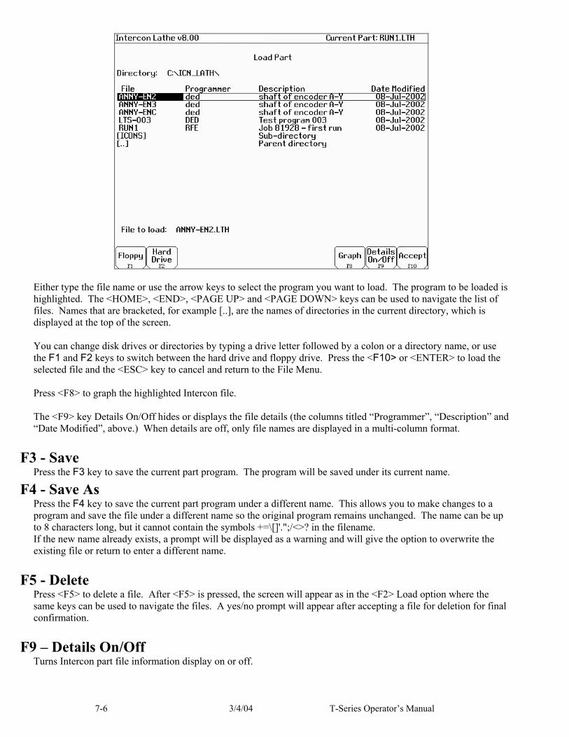
7-6 3/4/04 T-Series Operator’s Manual
Either type the file name or use the arrow keys to select the program you want to load. The program to be loaded is highlighted. The <HOME>, <END>, <PAGE UP> and <PAGE DOWN> keys can be used to navigate the list of files. Names that are bracketed, for example [..], are the names of directories in the current directory, which is displayed at the top of the screen. You can change disk drives or directories by typing a drive letter followed by a colon or a directory name, or use the F1 and F2 keys to switch between the hard drive and floppy drive. Press the <F10> or <ENTER> to load the selected file and the <ESC> key to cancel and return to the File Menu. Press <F8> to graph the highlighted Intercon file. The <F9> key Details On/Off hides or displays the file details (the columns titled “Programmer”, “Description” and “Date Modified”, above.) When details are off, only file names are displayed in a multi-column format.
F3 - Save Press the F3 key to save the current part program. The program will be saved under its current name.
F4 - Save As Press the F4 key to save the current part program under a different name. This allows you to make changes to a program and save the file under a different name so the original program remains unchanged. The name can be up to 8 characters long, but it cannot contain the symbols +=\[]'.";/<>? in the filename. If the new name already exists, a prompt will be displayed as a warning and will give the option to overwrite the existing file or return to enter a different name.
F5 - Delete Press <F5> to delete a file. After <F5> is pressed, the screen will appear as in the <F2> Load option where the same keys can be used to navigate the files. A yes/no prompt will appear after accepting a file for deletion for final confirmation.
F9 – Details On/Off Turns Intercon part file information display on or off.

7-7 3/4/04 T-Series Operator’s Manual
Insert Operation Press the <F3> key or <Insert> key to access the Insert Operation Menu. From this menu, you can add operations to a part program
The operation is added before the currently highlighted operation. The block number is shown to the left. The operations you can insert are listed at the bottom of the screen. Pressing the function key that corresponds to an operation will bring up the Edit Operation Menu for that operation. NOTE: For operations that use negative side tooling (see page 3-14) X values will be negative, such as starting and ending diameters in a turning cycle. Roughing and finishing tools are the same and the user is required to do tool positioning for tool changes.
F1 - Line Press the F1 key at the Insert Operation Menu to insert a linear operation.
Press the <F1> key or <Space> key to toggle between "Rapid" and "Feedrate" options when necessary and press the F10 key to accept the entries. Use the up and down arrow keys to move between fields. Press the <ESC> key to cancel and return to the Insert menu.
End (X,Z)
Z+
X+

7-8 3/4/04 T-Series Operator’s Manual
The destination of the linear move can be given in terms of the end point coordinates or as the counterclockwise angle from the 3 o ' clock position to the line and the length of the line (polar coordinates). Press the F3 key to hide modal fields. Press this key again to show those fields. Press the F4 key to hide the polar coordinates. Press this key again to display those fields. Linear Type: Enter the type of linear move you want to make (Rapid or Feedrate). This field can be toggled between Rapid and Feedrate. A rapid move is a non-cutting positioning move made at the maximum rate. A feedrate move is a cutting move made at the programmed feedrate. When performing a cutting operation, this must be toggled to Feedrate. End X: Enter the X coordinate of the end position of the linear move. You can toggle between absolute and incremental position. When toggled to absolute, enter the absolute position, with reference to the part zero. When toggled to incremental, an INC will appear next to the entry. In this mode, enter the X distance from the preceding end position. End Z: Enter the Z coordinate of the end position of the linear move. You can toggle between absolute and incremental position. When toggled to absolute, enter the absolute position, with reference to the part zero. When toggled to incremental, an INC will appear next to the entry. In this mode, enter the Z distance from the last preceding end position. Angle: The destination can also be determined with an angle from the three o'clock position. Enter this angle in conjunction with the length to determine the end point of the linear move. Length: Enter the length of the linear move. The length, along with the previously entered angle, will be used to calculate the end point of the move. Connect Type: When two feedrate moves are performed consecutively, you can chose the style in which they are connected. You can toggle this field between the following options: None, Bl Chamf (Dist), Chamf (Dist), Bl Chamf (Len), Chamf (Len), or Radius. When set to none, the linear operations are connected at the point of intersection. There is now two chamfer types: Distance and Length. For Distance Chamfers the operator specifies the amount of distance to be removed from the ends of the two linear segments. The chamfer connects the two shortened segments. If a Length Chamfer is chosen, the linear moves are connected by a chamfer of a specified length. Both chamfer types have a blended version. When blend chamfer is chosen, the linear moves are connected by a chamfer with rounded corners. When radius is chosen, a rounded corner connects the two linear moves. ● NOTE: Chamfers and blend chamfers in programs created with pre 8.10 Intercon are Length chamfers. ● NOTE: Chamfer and blend chamfer cannot be used to connect to an arc. Connect Radius: Enter the radius of the rounded corner used to connect two feedrate moves. Chamfer Distance: Enter the Distance to be removed from the end of each linear segment. Chamfer Length: Enter the length of the chamfer you want to connect two linear feedrate moves. Tool Num/Offset: Enter the tool number and offset number used. The first two digits is the tool number; the last two digits is the offset number. You can also press F2 to go to the tool library to select another tool and/or make changes to the tool library. Then, press F10 to accept. Feedrate: Enter the desired cutting feedrate. You can toggle between feed/min and feed/rev. Spindle Speed: Enter the desired spindle speed. You can toggle between RPM or CSS. When toggled to RPM, a constant RPM will be maintained. When toggled to CSS, a constant surface speed will be maintained. Cutter Compensation: Set cutter compensation. You can toggle between None, Right and Left.
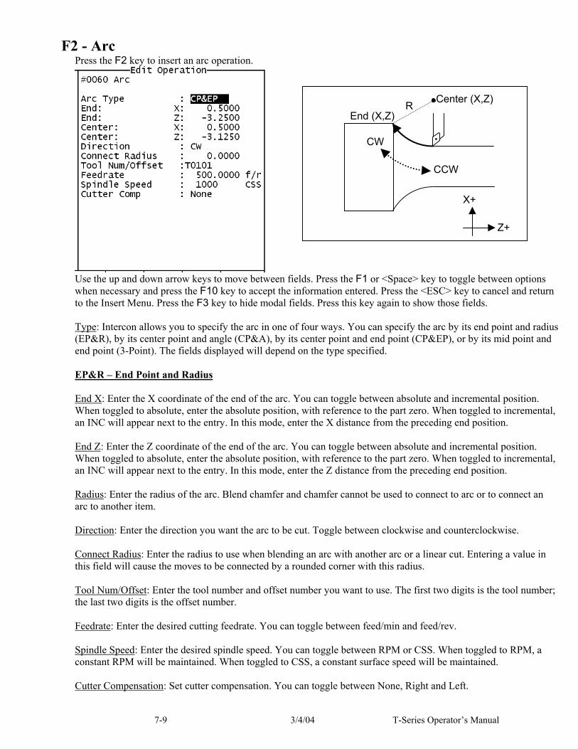
7-9 3/4/04 T-Series Operator’s Manual
F2 - Arc Press the F2 key to insert an arc operation.
Use the up and down arrow keys to move between fields. Press the F1 or <Space> key to toggle between options when necessary and press the F10 key to accept the information entered. Press the <ESC> key to cancel and return to the Insert Menu. Press the F3 key to hide modal fields. Press this key again to show those fields. Type: Intercon allows you to specify the arc in one of four ways. You can specify the arc by its end point and radius (EP&R), by its center point and angle (CP&A), by its center point and end point (CP&EP), or by its mid point and end point (3-Point). The fields displayed will depend on the type specified. EP&R – End Point and Radius End X: Enter the X coordinate of the end of the arc. You can toggle between absolute and incremental position. When toggled to absolute, enter the absolute position, with reference to the part zero. When toggled to incremental, an INC will appear next to the entry. In this mode, enter the X distance from the preceding end position. End Z: Enter the Z coordinate of the end of the arc. You can toggle between absolute and incremental position. When toggled to absolute, enter the absolute position, with reference to the part zero. When toggled to incremental, an INC will appear next to the entry. In this mode, enter the Z distance from the preceding end position. Radius: Enter the radius of the arc. Blend chamfer and chamfer cannot be used to connect to arc or to connect an arc to another item. Direction: Enter the direction you want the arc to be cut. Toggle between clockwise and counterclockwise. Connect Radius: Enter the radius to use when blending an arc with another arc or a linear cut. Entering a value in this field will cause the moves to be connected by a rounded corner with this radius. Tool Num/Offset: Enter the tool number and offset number you want to use. The first two digits is the tool number; the last two digits is the offset number. Feedrate: Enter the desired cutting feedrate. You can toggle between feed/min and feed/rev. Spindle Speed: Enter the desired spindle speed. You can toggle between RPM or CSS. When toggled to RPM, a constant RPM will be maintained. When toggled to CSS, a constant surface speed will be maintained. Cutter Compensation: Set cutter compensation. You can toggle between None, Right and Left.
End (X,Z)Center (X,Z)
R
CW
CCW
Z+
X+

7-10 3/4/04 T-Series Operator’s Manual
CP&A – Center Point and Angle Center X: Enter the X coordinate of the center of the arc. You can toggle between absolute and incremental position. When toggled to absolute, enter the absolute position, with reference to the part zero. When toggled to incremental, an INC will appear next to the entry. In this mode, enter the X distance from the last point. Center Z: Enter the Z coordinate of the center of the arc. You can toggle between absolute and incremental position. When toggled to absolute, enter the absolute position, with reference to the part zero. When toggled to incremental, an INC will appear next to the entry. In this mode, enter the Z distance from the last point. Angle: Enter the angle of the arc. Direction: Enter the direction you want the arc to be cut. Toggle between clockwise and counterclockwise. Connect Radius: Enter the radius to use when blending an arc with a linear cut or another type of arc. Entering a value in this field will cause the arc and a linear move to be connected by a rounded corner with this radius. Tool Num/Offset: Enter the tool number and offset number you want to use. The first two digits is the tool number; the last two digits is the offset number. Feedrate: Enter the desired cutting feedrate. You can toggle between feed/min and feed/rev. Spindle Speed: Enter the desired spindle speed. You can toggle between RPM or CSS. When toggled to RPM, a constant RPM will be maintained. When toggled to CSS, a constant surface speed will be maintained. Cutter Compensation: Set cutter compensation. You can toggle between None, Right and Left. CP&EP – Center Point and End Point End X: Enter the X coordinate of the end of the arc. You can toggle between absolute and incremental position. When toggled to absolute, enter the absolute position, with reference to the part zero. When toggled to incremental, an INC will appear next to the entry. In this mode, enter the X distance from the last point. End Z: Enter the Z coordinate of the end of the arc. You can toggle between absolute and incremental position. When toggled to absolute, enter the absolute position, with reference to the part zero. When toggled to incremental, an INC will appear next to the entry. In this mode, enter the Z distance from the last point. Center X: Enter the X coordinate of the center of the arc. You can toggle between absolute and incremental position. When toggled to absolute, enter the absolute position, with reference to the part zero. When toggled to incremental, an INC will appear next to the entry. In this mode, enter the X distance from the last point. Center Z: Enter the Z coordinate of the center of the arc. You can toggle between absolute and incremental position. When toggled to absolute, enter the absolute position, with reference to the part zero. When toggled to incremental, an INC will appear next to the entry. In this mode, enter the Z distance from the last point. Direction: Enter the direction you want the arc to be cut. Toggle between clockwise and counterclockwise. Connect Radius: Enter the radius to use when blending an arc with a linear cut or another type of arc. Entering a value in this field will cause the arc and a linear move to be connected by a rounded corner with this radius. Tool Num/Offset: Enter the tool number and offset number you want to use. The first two digits is the tool number; the last two digits is the offset number. Feedrate: Enter the desired cutting feedrate. You can toggle between feed/min and feed/rev.

7-11 3/4/04 T-Series Operator’s Manual
Spindle Speed: Enter the desired spindle speed. You can toggle between RPM or CSS. When toggled to RPM, a constant RPM will be maintained. When toggled to CSS, a constant surface speed will be maintained. Cutter Compensation: Set cutter compensation. You can toggle between None, Right and Left. 3-POINT (Start Point, Mid Point, and End Point) Mid X: Enter the X coordinate of a point on the arc between the start point and the end point. You can toggle between absolute and incremental position. When toggled to absolute, enter the absolute position, with reference to the part zero. When toggled to incremental, an INC will appear next to the entry. In this mode, enter the X distance from the last point. Mid Z: Enter the Z coordinate of a point on the arc between the start point and the end point. You can toggle between absolute and incremental position. When toggled to absolute, enter the absolute position, with reference to the part zero. When toggled to incremental, an INC will appear next to the entry. In this mode, enter the Z distance from the last point. End X: Enter the X coordinate of the end of the arc. You can toggle between absolute and incremental position. When toggled to absolute, enter the absolute position, with reference to the part zero. When toggled to incremental, an INC will appear next to the entry. In this mode, enter the X distance from the last point. End Z: Enter the Z coordinate of the end of the arc. You can toggle between absolute and incremental position. When toggled to absolute, enter the absolute position, with reference to the part zero. When toggled to incremental, an INC will appear next to the entry. In this mode, enter the Z distance from the last point. Direction: Enter the direction you want the arc to be cut. Toggle between clockwise and counterclockwise. Connect Radius: Enter the radius to use when blending an arc with a linear cut or another type of arc. Entering a value in this field will cause the arc and a linear move to be connected by a rounded corner with this radius. Tool Num/Offset: Enter the tool number and offset number you want to use. The first two digits is the tool number; the last two digits is the offset number. Feedrate: Enter the desired cutting feedrate. You can toggle between feed/min and feed/rev. Spindle Speed: Enter the desired spindle speed. You can toggle between RPM or CSS. When toggled to RPM, a constant RPM will be maintained. When toggled to CSS, a constant surface speed will be maintained. Cutter Compensation: Set cutter compensation. You can toggle between None, Right and Left.

7-12 3/4/04 T-Series Operator’s Manual
F3 - Drill Press the F3 key to insert a Drill operation. This operation allows you to either do normal Drilling or off-center Boring operations. Both the Drilling and Boring type operations are actually the same, except in the types of tools used and position X field.
Press F5 to toggle between Bore and Drill. If the operation is toggled into Bore mode, then you can modify the Position X coordinate, which can be specified to be off-center (usually by the tool diameter). NOTE: Insert drills and end mills can be used to drill and bore holes into a part. In order to bore with a specific tool, it will need an offset value for that tool so diameters can be controlled. If for example a .750 diameter insert drill is used to drill a hole in a part, but the final diameter of the hole needs to be 1.250, toggle to the boring cycle and for Position X enter .750. This will offset the center of the drill to the center of the part. After the hole is in the part, use a profile or a turning cycle to finish the hole to the 1.250 diameter, using the same tool. Press the F1 key to toggle between options when necessary and the F10 key to accept the entries. Use the up and down arrow keys to move between fields. Press the <ESC> key to cancel and return to the Intercon Main Menu.
Centerline Drilling
Off-Center Boring with an Insert Drill
Drill or Bore
Peck Drill or Peck Bore
Deep Hole Drill or
Deep Hole Bore
Feed move
Rapid move
Depth Z (Dwell occurs here) Depth IncrementRapid Clearance
Retract Amount
Z Surface Height
Clearance Amount
Z+
X+

7-13 3/4/04 T-Series Operator’s Manual
Surface Z: Enter the position of the front face of the work piece. Type: Enter the type of Drilling or Boring you want to perform. You can toggle between Drill, Peck Drill, and Deep Hole Drill, OR if you have toggled into Bore mode with F5, you can toggle between Bore, Peck Bore, and Deep Bore. Position X: (Valid only while in Bore mode) Enter the diameter for the tool being used. Depth Z: Enter the depth of the hole to drill. This is the Z distance from the surface height. Depth Increment: Enter the cut depth increment used during the cycle. This field only applies when the type field has been set to Peck Drill, Deep Hole Drill, Peck Bore, or Deep Hole Bore. Retract Amount: Enter the amount the drill should retract before making another incremental depth cut. This field only applies when the type field has been set to Peck Drill or Peck Bore. Rapid Clearance Enter the amount above the uncut material the drill will rapid to on subsequent cuts. This field only applies when the type field has been set to Deep Hole Drill or Deep Hole Bore Dwell Time: Enter the amount of time in seconds that the drill should dwell at the bottom of the hole. Tool Num/Offset: Enter the tool number and offset number you want to use. The first two digits is the tool number; the last two digits is the offset number. Plunge Rate: Enter the feedrate at which you want to drill the hole. Toggle between feed/min and feed/rev. Spindle Speed: Enter the spindle speed in RPM Pre/Post Cycle Pos.: Allows you to select if you want to move to a specified position before the cycle and/or a position after the cycle. Once toggled from “None” 2 fields appear to enter the desired position.

7-14 3/4/04 T-Series Operator’s Manual
F4 - Tap The tap operation allows you to tap into the parts centerline (cutting in the negative Z direction). The operation may use a floating tap holder or rigid tap, with spindle reversal, or a self-reversing tap head. Press the F4 key to insert a center tapping operation.
Press the F1 key to toggle between options when necessary and the F10 key to accept the entries. Use the up and down arrow keys to move between fields. Press the <ESC> key to cancel and return to the Insert Menu. Tap Head Type: Enter the type of tap head you will be using. You can toggle between floating and reversing. Z Surface Height: Enter the Z position of the surface you are tapping. Depth Z: Enter the depth of the hole you want to tap. You can toggle between absolute Z and an incremental value from the parts surface. This is the Z distance from the surface height. Thread Pitch: Enter the desired threads/unit. Thread Lead: Enter the desired units/thread. Dwell Time: Enter the time in seconds the tap should dwell at the bottom of the hole. This is to allow time for the spindle to reverse rotational direction. Used for Floating Tap only. Tool Num/Offset: Enter the tool number and offset number you want to use. The first two digits is the tool number; the last two digits is the offset number. Spindle Speed: Enter the spindle speed in RPM. A constant RPM value will be maintained. Pre/Post Cycle Pos.: Allows you to select if you want to move to a specified position before the cycle and/or a position after the cycle. Once toggled from “None” 2 fields appear to enter the desired position.
Depth Z (Dwell occurs here)
Z Surface Height
Clearance Amount
CW
CCW Z+
X+
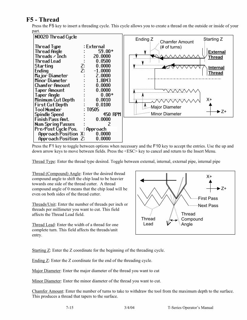
7-15 3/4/04 T-Series Operator’s Manual
F5 - Thread Press the F5 key to insert a threading cycle. This cycle allows you to create a thread on the outside or inside of your part.
Press the F1 key to toggle between options when necessary and the F10 key to accept the entries. Use the up and down arrow keys to move between fields. Press the <ESC> key to cancel and return to the Insert Menu. Thread Type: Enter the thread type desired. Toggle between external, internal, external pipe, internal pipe Thread (Compound) Angle: Enter the desired thread compound angle to shift the chip load to be heavier towards one side of the thread cutter. A thread compound angle of 0 means that the chip load will be even on both sides of the thread cutter. Threads/Unit: Enter the number of threads per inch or threads per millimeter you want to cut. This field affects the Thread Lead field. Thread Lead: Enter the width of a thread for one complete turn. This field affects the threads/unit entry. Starting Z: Enter the Z coordinate for the beginning of the threading cycle. Ending Z: Enter the Z coordinate for the end of the threading cycle. Major Diameter: Enter the major diameter of the thread you want to cut Minor Diameter: Enter the minor diameter of the thread you want to cut. Chamfer Amount: Enter the number of turns to take to withdraw the tool from the maximum depth to the surface. This produces a thread that tapers to the surface.
Internal Thread
External Thread
Starting Z Chamfer Amount (# of turns)
Ending Z
Major Diameter Minor Diameter Z+
X+
First Pass Next Pass
Thread Compound Angle
Thread Lead
Z+
X+

7-16 3/4/04 T-Series Operator’s Manual
Taper Amount: Enter the amount the surface rises over the length of the surface you want to thread – normally negative amount for external, positive amount for internal. This field affects the thread angle field. Taper Angle: Enter the angle that the surface tapers to – normally negative angle for external, positive angle for internal. This field affects the taper amount entry. Minimum Cut Depth: Enter the minimum amount of material to remove during a pass. The threading cycle will remove larger amounts of material initially but will work down to this value. First Cut Depth: Enter the amount of material to be removed during the first cut. Tool Num/Offset: Enter the tool number and offset number you want to use. The first two digits is the tool number; the last two digits is the offset number. Spindle Speed: Enter the desired spindle speed for the threading cycle. You can toggle between RPM or CSS. When toggled to RPM, a constant RPM will be maintained. When toggled to CSS, a constant surface speed will be maintained. Finish Pass Amount: Enter the amount of material to leave for a finishing pass. Num Spring Passes: Enter the number of passes to make at the finish diameter. Pre/Post Cycle Pos.: Allows you to select if you want to move to a specified position before the cycle and/or a position after the cycle. Once toggled from “None” 2 fields appear to enter the desired position.
External Thread External Pipe Thread
Internal Thread Internal Pipe Thread
MajorDiameter Minor
Diameter
Taper Angle (-)
Major Diameter
MinorDiameterTaper
Amount (-)
Major Diameter Minor
DiameterMajor
Diameter Minor Diameter
Taper Angle (+)
Taper Amount (+)
Z+
X+

7-17 3/4/04 T-Series Operator’s Manual
F6 - Profile Press the F6 key to insert a profile. The profile operation allows you to define a profile with lines and arcs that will be produced with a cleanout cycle. (NOTE): Do not move Z until the 2nd line of the profile to avoid over and under cutting of part.
Example Profile Press the F1 key to toggle between options when necessary. When at least one operation is present in the profile, you can press the F10 to accept the profile. Profile Type: Enter the type of profile you want to produce. Toggle between diameter and end face. Choosing diameter will cause the cleanout cycle to be performed along the diameter while choosing end face will cause the cleanout cycle to be performed along the face. Start X: Enter the X coordinate of the start of the profile. Allow for clearance. Start Z: Enter the Z coordinate of the start of the profile. Allow for clearance. Start X and Start Z are where the tool rapids to before it starts the cleanout cycle. ● NOTE: Intercon determines whether the cleanout cycle is external or internal by the start position of the profile and the end position of the first move in the profile. If the end position of the first move is lower than the start position of the profile, the cleanout cycle is external. For external cleanout cycles, all profile operations must be lower than the start point. If the end position of the first move is higher than the start position of the profile, the cleanout cycle is internal. For internal cleanout operations, all profile operations must be higher than the start point. Depth of Cut: Enter the amount to remove per pass per side in the cleanout cycle. Rough Tool: Enter the tool number and offset number you want to use during the roughing portion of the cleanout cycle. The first two digits is the tool number; the last two digits is the offset number. Rough Feedrate: Enter the desired feedrate for the roughing portion of the cycle. You can toggle between Feed Per Revolution (f/r) or Feed Per Minute (f/m). Note that this Rough Feedrate is different from the Finish Feedrates specified within each of the Line and Arc operations inside the profile.

7-18 3/4/04 T-Series Operator’s Manual
Rough Spin Speed: Enter the desired spindle speed for the roughing portion of the cycle. You can toggle between RPM or CSS. When toggled to RPM, a constant RPM will be maintained. When toggled to CSS, a constant surface speed will be maintained. Note that this Rough Spin Speed is different from the Finish Spindle Speeds specified within each of the Line and Arc operations inside the profile. Stock to Leave X: Enter the amount of stock to leave on the X-axis to be removed by the finishing pass(es). Stock to Leave Z: Enter the amount of stock to leave on the Z-axis to be removed by the finishing pass(es). Cutter Compensation: Set cutter compensation. You can toggle between None, Right and Left. After entering these fields, define the profile you want to cut out with lines and arcs. Intercon allows you to insert Lines, Arcs, and Finish Passes within a profile. Lines and Arcs are described earlier. The Finish Pass is described later. Rapid Between Cuts: Choose whether or not the moves between rough passes are to be done as Rapid or Feedrate. You can toggle between Yes and No. ● NOTE: The Spindle Speeds and Feedrates specified within each of the individual Line and Arc operations inside the profile are not used by the roughing portion of the cycle. However they will later be utilized by the Finish Pass, if it is defined.

7-19 3/4/04 T-Series Operator’s Manual
Finish Pass (For Profiles Only)
The Finish Pass is a special operation that only applies to profiles. At least two operations must be present in the profile before you can insert a finishing pass. Multiple finishing passes can be inserted. Once a finish pass is inserted, you can no longer make changes in the profile without going back out to the Insert Operations Menu. ● NOTE: The number of passes made for a finish operation is determined by the greater of
stock to leave x (Profile Operation) OR stock to leave z (Profile Operation) depth of cut x (Finish Operation) depth of cut z (Finish Operation)
Start Block: Enter the block number in the profile that the finishing pass should start on. End Block: Enter the block number in the profile that the finishing pass should end on. Depth of Cut Z: Enter the amount of material to remove from the Z-axis per pass. 0 will be one pass. Depth of Cut X: Enter the amount of material to remove from the X-axis per pass. 0 will be one pass ●If both are 0, then there will be one pass. Tool Num/Offset: Enter the tool number and offset number you want to use for the finish pass. The first two digits is the tool number; the last two digits is the offset number. This field is disabled if G28 is not used for tool changes. Cutter Compensation: Set cutter compensation. You can toggle between None, Right and Left. ● NOTE: The Spindle Speeds and Feedrates specified within each of the individual Line and Arc operations defined inside the profile will determine the Spindle Speeds and Feedrates for the Finish Pass. That is why there is no way to specify a Spindle Speed or Feedrate on the Finish Pass Operation page.

7-20 3/4/04 T-Series Operator’s Manual
F7 – Turning A turning cycle is a repetitive cycle used to cut an outside or inside diameter to a specified dimension within a specified Z range. Press the F7 key to insert a turning cycle into your part program.
Press the F1 key to toggle between options when necessary and the F10 key to accept the entries. Use the up and down arrow keys to move between fields. Press the <ESC> key to cancel and return to the Insert menu. Turning Type: Enter the type of turning you want to use. Toggle between diameter/radius and end face. Choosing diameter/radius will cause the cycle to remove material in a direction parallel to the Z-axis, along the diameter or radius. Choosing end face will cause the cycle to remove material in a direction parallel to the X-axis, along the face. Starting Diameter/Radius: Enter the diameter at which you want the cycle to start. Ending Diameter/Radius: Enter the diameter at which you want the cycle to finish. ● NOTE: When turning an inside diameter, the starting diameter must be less than the ending diameter. When turning an outside diameter, the starting diameter must be greater than the ending diameter. Starting Z: Enter the starting Z value for the turning cycle. Ending Z: Enter the ending Z value for the turning cycle. Taper Amount: Enter the amount that you want to taper from the starting diameter to the ending diameter. This entry affects the taper angle. For diameter turning, enter a positive value to taper from the ending diameter + taper amount to the ending diameter. Enter a negative value to taper from the ending diameter - taper amount to the ending diameter amount. For end face turning, enter a positive value to taper from end Z taper + taper amount to end Z. Enter a negative value to taper from end Z- taper amount to end Z.
Z+
X+
Feed move
Rapid move
End Face Turning
Diameter/Radius Turning

7-21 3/4/04 T-Series Operator’s Manual
● NOTE: The taper amount must be less than the depth of cut. Taper Angle: Enter the angle you want to use to taper. This angle is used to determine the taper amount. For diameter turning, enter a positive value to taper from the ending diameter + taper amount to the ending diameter. Enter a negative value to taper from the ending diameter - taper amount to the ending diameter amount. For end face turning, enter a positive value to taper from end Z taper + taper amount to end Z. Enter a negative value to taper from end Z- taper amount to end Z. Depth of Cut: Enter the amount to remove per pass Rough Tool: Enter the tool and offset number to use for the roughing portion of the cycle. The first two digits is the tool number; the last two digits is the offset number. Rough Feedrate: Enter the cutting feedrate for the roughing portion of the cycle. You can toggle between feed/min and feed/rev. Rough Spin Speed: Enter the spindle speed for the roughing portion of the cycle. You can toggle between RPM and CSS. When toggled to RPM, a constant RPM will be maintained. When toggled to CSS, a constant surface speed will be maintained. Finish Pass Amount: Enter the amount you want the roughing portion of the cycle to leave to be removed by the finish pass. This is a radial amount. If the amount entered is zero, a finish pass will not be performed. Finish Tool: Enter the tool and offset to use during the finishing pass. The first two digits is the tool number; the last two digits is the offset number. This field is disabled if G28 is not used for tool changes. Finish Feedrate: Enter the cutting feedrate for the finishing pass. You can toggle between feed/min and feed/rev. Finish Spin Speed: Enter the spindle speed for the finishing pass. You can toggle between RPM and CSS. When toggled to RPM, a constant RPM will be maintained. When toggled to CSS, a constant surface speed will be maintained. Cutter Compensation: Set cutter compensation. You can toggle between None, Right and Left.
Taper Angle (+)
Radius/Diameter Turning End Face Turning
Z+
X+ Ending Radius/Diameter
Ending Z
Ending Z
Ending Radius/Diameter
Taper Amount (+)
● NOTE: Only one pass is shown in each of the illustrations.
1
2 3
4
1
2
3
4

7-22 3/4/04 T-Series Operator’s Manual
Return Feed Amount: This is a special field that activates 3-sided turning. If the value is 0, then the normal 2-sided turning will be performed. If this value is more than 0, then 3-sided turning will be performed. On 3-sided turning, this field specifies the length of the returning feedrate move.
Pre/Post Cycle Pos.: Allows you to select if you want to move to a specified position before the cycle and/or a position after the cycle. Once toggled from “None” 2 fields appear to enter the desired position.
Normal 2-sided Turning Cycle 3-sided Turning Cycle
Feed move
Rapid move
(Return Feed Amount = 0) Return Feed Amount > 0
Z+
X+
● NOTE: Only one pass is shown in each of the illustrations.
1
2
3
4
1
2
3
4 5

7-23 3/4/04 T-Series Operator’s Manual
F8 - Groove
The grooving operation allows you to cut a groove of specified width and depth in a specified location. Press the F8 key to insert a grooving operation. Press the F1 key to toggle between options when necessary and the F10 key to accept the entries. Use the up and down arrow keys to move between fields. Press the <ESC> key to cancel and return to the Insert menu. Type: Toggle between four options for the type of grooving. The four options are outside, inside, front and back Choosing outside will cause the operation to cut the groove on the outside diameter of the work piece. Choosing inside will cause the operation to cut the groove on the inside diameter of the work piece. Choosing front will cause the operation to cut the groove on the front face of the work piece (see example below). Choosing back will cause the operation to cut the groove on the back face of the work piece.
Starting Diameter/Radius: Enter the position of the surface on which the groove will be produced.
Groove Cut on Outside Diameter
Groove Cut on Face of Part

7-24 3/4/04 T-Series Operator’s Manual
Ending Diameter/Radius: Enter the grooves ending dimension. Depth Increment: Enter the depth increment for the grooving cycle. This is the amount removed per plunge in the peck cutting cycle used to produce the groove. Starting Z: Enter the starting position of the groove. Ending Z: Enter the ending position of the groove. For the outside or inside diameter, it will be a Z value. For the front or back face, this will be an X value. You can toggle between absolute and incremental position. When toggled to absolute, enter the absolute position, with reference to the part zero. When toggled to incremental, an INC will appear next to the entry. In this mode, enter the X distance from the last point. Width Increment: Enter the width increment for the grooving cycle. This is the stepover amount for the cleanout cycle used to produce the width. Corner Finish: Enter the type of corner finish you want. Toggle between square, radius, chamfer (Distance or Length), and blend chamfer (Distance or Length). Shown below is each type of corner that will be produced for the groove. Corner Radius: Enter the radius for the rounded corner when corner finish is set to radius. Chamfer Distance: Enter the Distance to be removed from the end of each linear segment. Chamfer Length: Enter the length of the chamfer you want for the corner finish. Rough Tool Number: Enter the tool number and offset number to use for the roughing portion of the cycle. The first two digits is the tool number; the last two digits is the offset number. Rough Feedrate: Enter the cutting feedrate for the roughing portion of the cycle. You can toggle between feed/min and feed/rev. Rough Spin Speed: Enter the spindle speed for the roughing cycle. You can toggle between RPM and CSS. When toggled to RPM, a constant RPM will be maintained. When toggled to CSS, a constant surface speed will be maintained. Finish Pass Amount: Enter the amount you want the roughing portion of the cycle to leave to be removed by the finish pass. This is a radial amount. If the amount entered is zero, a finish pass will not be performed. Finish Tool Number: Enter the tool number and offset number to use during the finishing pass. The first two digits is the tool number; the last two digits is the offset number. This field is disabled if G28 is not used for tool changes. Finish Feedrate: Enter the cutting feedrate for the finishing pass. You can toggle between feed/min and feed/rev. Finish Spindle: Enter the spindle speed for the finishing pass. You can toggle between RPM and CSS. When toggle to RPM, a constant RPM will be maintained. When toggled to CSS, a constant surface speed will be maintained. Pre/Post Cycle Pos.: Allows you to select if you want to move to a specified position before the cycle and/or a position after the cycle. Once toggled from “None” 2 fields appear to enter the desired position.

7-25 3/4/04 T-Series Operator’s Manual
F9 - Cutoff The cutoff operation allows you to cut off the part with a cutoff tool. Press the F1 key to toggle between options when necessary and the F10 key to save changes. Use the up and down arrow keys to move between fields. Press the <ESC> key to cancel and return to the Insert Menu. Type: Enter the type of cut to cut off the work piece. You can toggle between continuous and peck. Choosing continuous will cause the work piece to be cutoff with a continuous cut. Choosing peck will cause the work piece to be cutoff in incremental moves.
Peck Increment: When the type field is set to peck, enter the increment amount used in cutting the part off. When the type field is set to continuous, this field will not be shown. Z position: Enter the Z position of the cut. Starting Diameter: Enter the diameter at which the cutoff is to start. Ending Diameter: Enter the diameter at which the cutoff is to finish.
Corner Finish: Enter the type of corner finish you want. Toggle between square, radius, chamfer (Distance or Length), and blend chamfer (Distance or Length). Shown below is each type of corner that will be produced for the cutoff. Corner finish will be on the start diameter. Corner Radius: Enter the radius of the corner you want for the corner finish. This field is only shown when radius is chosen for the corner finish. Chamfer Distance: Enter the Distance to be removed from the end of each linear segment. Chamfer Length: Enter the length of the chamfer you want for the corner finish. This field is only shown when chamfer is chosen for corner finish. Tool Num/Offset: Enter the tool number and offset number you want to use. The first two digits is the tool number; the last two digits is the offset number. Feedrate: Enter the cutting feedrate to cutoff the workpiece. You can toggle between feed/min and feed/rev. Spin Speed: Enter the spindle speed for the work piece cutoff. You can toggle between RPM and CSS. When toggle to RPM, a constant RPM will be maintained. When toggled to CSS, a constant surface speed will be maintained. Pre/Post Cycle Pos.: Allows you to select if you want to move to a specified position before the cycle and/or a position after the cycle. Once toggled from “None” 2 fields appear to enter the desired position.

7-26 3/4/04 T-Series Operator’s Manual
F10 - Other Press the F10 key to add a comment to your program or to enter in any M and G code available on your control. If the 3rd axis label in the machine configuration is set to ‘C’ and parameter 93 is set for C axis operation, or if the 4th axis label in the machine configuration is set to ‘C’ and parameter 94 is set for C axis operation, there will be options for C Axis and C Indexing operations shown. The options shown at the bottom of the screen are shown below. Press the <ESC> key to cancel and return to the Insert Operation Menu. F1 - Comment Press the F1 key to enter a comment. The comment can be up to 35 characters long and will be displayed in the generated CNC program.
F2 – M&G Code Press the F2 key to enter M and G codes directly into the part program.
After entering the M and G codes you may press the F10 key to accept the entry or the <ESC> key to cancel and return to the Insert Operation Menu. F3 – C Axis Press the F3 key to enter the C Axis edit operation screen.
Press the F1 key or space bar to toggle between on and off. Press the F10 key to accept the entry or the <ESC> key to cancel and return to the Insert Operation Menu.

7-27 3/4/04 T-Series Operator’s Manual
F4 – C Index Press the F4 key to enter the C Indexing operation screen.
Press the F1 key to toggle between incremental (INC) and absolute (ABS) positioning. Press the F3 key to toggle the brake fields off and on. Degrees: The number of degrees you want to move the C axis. This value can be positive or negative. Minutes: The number of minutes you want to move the C axis. Values for this field are between 0 and 59. Seconds: The number of seconds you want to move the C axis. Values for this field are between 0 and 59. Decimal degrees: This is another method of entering the number of degrees. If you choose to enter the movement of the C axis with the fields listed above, the value of this field will be calculated automatically. If you choose to enter the number of degrees with this field or make changes to it, then the degrees, minutes, and seconds will be calculated or changed automatically. Values for this field can be positive or negative. Brake On M code: The number of the M code to output for the braking function. The brake fields must be toggled on to allow the editing of this field. When the brake fields are on, code will be output to turn off the brake, position the C axis, and then turn on the brake. Brake Off M code: The number of the M code to output for the braking function. The brake fields must be toggled on to allow the editing of this field. Press the F10 key to accept the entry or the <ESC> key to cancel and return to the Insert Operation Menu.

7-28 3/4/04 T-Series Operator’s Manual
Graphics Press the F8 key from the Intercon Main Menu, the File Menu, or from any Edit Operation Menu to view graphics. A wire frame of your part will appear.
F3 - Range Press the F3 key to graph a portion of a part program.
Start Block: Enter the start block number of the portion of the part program you want to graph. End Block: Enter the end block number of the portion of the part program you want to graph. Press the F10 key to accept entries and the <ESC> key to cancel.
F4 - Time Press the F4 key to get an estimate of the time it will take to produce the part. F5 - Redraw Press the F3 key to redraw the graphic. F6 - Pan Press the F6 key to move the part around the graph window. After pressing this key, crosshatches will appear. Move the crosshatches around with the arrow keys. Pick a location on the part with the crosshatches and press the F6 key to pan this to the center of the graph window. F7 - Zoom In Press the F7 key to zoom into the part. You will zoom in to the center of the graph window. F8 - Zoom Out Press the F8 key to zoom out from the part. You will zoom out from the center of the graph window. F9 - Zoom All Press the F9 key to fit the entire part within the graph window. 1 – 9, 0, Space – Feed Rate Override & Hold If no jog panel is attached (or “Keyboard” has been selected as the jog panel type) the number keys 1 – 9 and 0 choose feed rate overrides 10% - 90% and 100%, respectively. The space bar toggles feed hold on and off.

7-29 3/4/04 T-Series Operator’s Manual
Math Help Intercon provides a math assistance function to solve the trigonometric problems common in part drawings. To enter Math Help, press <F6> from any Edit Operation screen. The first time that you invoke Math Help, the following screen appears which shows all available solvers:
The figures on the right are a graphical representation of the highlighted solver on the left. Pressing <ENTER> will display another menu that has various fields particular to the type of problem that is being solved. The graphic below displays the Right Triangle Calculator menu. The options that are available on the function keys are the same for every type of math help solver and perform the following operations:

7-30 3/4/04 T-Series Operator’s Manual
F1 – Prev Soln F2 – Next Soln
The Prev Soln and Next Soln options will cycle backward and forward, respectively, through the available solution sets for math solvers that may have multiple solutions. A status line near the bottom left of the screen appears once a valid solution has been found. The solution status line indicates the total number of solutions and the solution number that is currently represented by the graphic display on the right. For example, in an Arc Tangent Arcs math help, the display solution status may be “- Solution 1 of 8 -“. In this case, the Prev Soln and Next Soln can be used to cycle through all eight of the solutions.
F3 – Clear All The Clear All option removes all solutions. It sets all fields for a particular solver to UNKNOWN.
F4 – Prev Solver F5 – Next Solver
The Prev Solver and Next Solver options cycle backward and forward, respectively, through the various math help solvers. These options are shortcuts which have the same effect as pressing <ESC> to reach the main math help menu, navigating to the previous or next math help option, and then pressing <ENTER>.
F6 – Hide Math The Hide Math option exits math help mode and returns to the operation edit menu. Pressing <F6> to invoke Math Help again will restore Math Help exactly as you left it.
F7 – Copy <<< F8 – Copy >>>
The Copy <<< option will move the value from the selected edit operation field into the selected math help menu field and the Copy >>> operation will move the value from the selected math help menu field into the selected edit operation field. For both options, the selected fields in the math help menu and the operation edit menu are advanced. If the graphical display is visible when choosing one of these options, the effect is to turn off the graphics display. Only when the graphics display is off will the Copy operations actually copy values and advance field selections. The currently selected fields have either a box drawn around them or are highlighted depending upon which menu is active. The active menu, which is either the math operation menu on the left hand side or the operation edit menu on the right hand side, depicts the selected field by highlighting the entire field. The non-active menu displays the active field with a box drawn around it. Use the arrow keys to select fields as described below.
F9 – Graphic On/Off The Graphic On/Off option will remove the graphical representation of the math help menu from the display. This is helpful before copying data between Intercon operations and Math Help.
(Arrow Keys) – Select Fields The <LEFT> and <RIGHT> arrow keys are used to navigate between the math menu and the edit menu. The <UP> and <DOWN> arrow keys are used to navigate within a menu. To choose fields for the “Copy” option, above, use the <UP> and <DOWN> arrow keys to highlight the desired field in the menu and use the <LEFT> or <RIGHT> arrow keys to switch menus.

7-31 3/4/04 T-Series Operator’s Manual
Other features common to all math help operations In some math help operations, there will be an asterisk ‘*’ character that appears immediately to the right of a field. This character marks the field as a “given” field, which means that the value of this field will be held constant in the process of solving the math equations.
F1 –Triangle:Right F2 –Triangle:Other
The screen will show UNKNOWN if the value of each parameter is not known. Math Help waits for known values to be entered, where: Point a, b, or c is the coordinate value for each corner of the triangle. Angle A, B, or C is the angle at each point of the triangle. Length of values are the distances between the points indicated. Continue adding all the known parameters. Select parameters using the arrow keys. When Math Help solves the remaining unknown values, the screen will display them.
F3 – Tangent: Line Arc
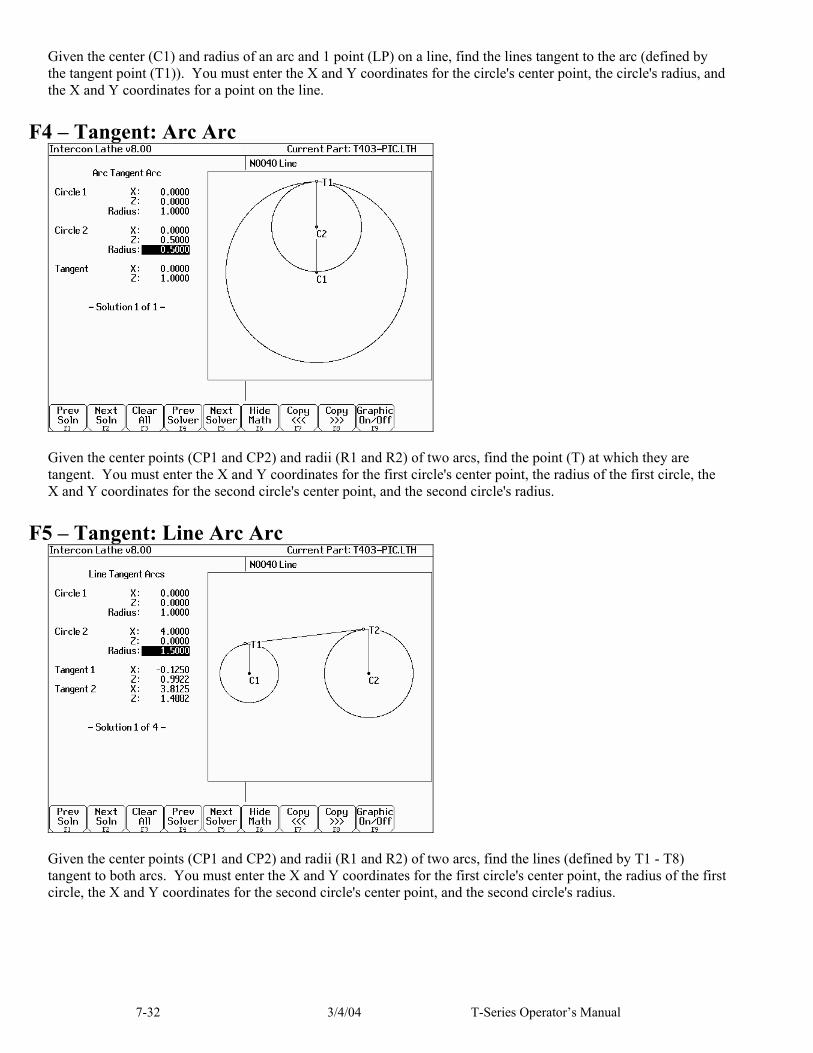
7-32 3/4/04 T-Series Operator’s Manual
Given the center (C1) and radius of an arc and 1 point (LP) on a line, find the lines tangent to the arc (defined by the tangent point (T1)). You must enter the X and Y coordinates for the circle's center point, the circle's radius, and the X and Y coordinates for a point on the line.
F4 – Tangent: Arc Arc
Given the center points (CP1 and CP2) and radii (R1 and R2) of two arcs, find the point (T) at which they are tangent. You must enter the X and Y coordinates for the first circle's center point, the radius of the first circle, the X and Y coordinates for the second circle's center point, and the second circle's radius.
F5 – Tangent: Line Arc Arc
Given the center points (CP1 and CP2) and radii (R1 and R2) of two arcs, find the lines (defined by T1 - T8) tangent to both arcs. You must enter the X and Y coordinates for the first circle's center point, the radius of the first circle, the X and Y coordinates for the second circle's center point, and the second circle's radius.

7-33 3/4/04 T-Series Operator’s Manual
F6 – Tangent: Arc Arc Arc
Given the center points (C1 and C2) and radii of two arcs and the radius of a third arc, find the center point of the third arc and the tangent points (T1 and T2). You must enter the radius of the tangent arc, the X and Y coordinates for the first circle's center point, the radius of the first circle, the X and Y coordinates for the second circle's center point, and the second circle's radius.
F7 – Intersection: Line Line
You must enter the X and Y coordinates for 1 point on each line, and also one of the following: * the X and Y coordinates for a second point * the X coordinate for a second point and the angle from horizontal * the Y coordinate for a second point and the angle from horizontal * the angle from horizontal only

7-34 3/4/04 T-Series Operator’s Manual
F8 – Intersection: Line Arc
Given the center (CP) and radius (R) of an arc, 1 point (LP1) and either a second point (LP2) or one coordinate (LP2 X or Y) and the angle from horizontal, find the intersection point(s) (I1 and I2). You must enter the X and Y coordinates for the circle's center point, the circle's radius, the X and Y coordinates for one point on the line, and one of the following: * the X and Y coordinates of a second point on the line * the X coordinate of a second point and the angle from horizontal * the Y coordinate of a second point and the angle from horizontal
F9 – Intersection: Arc Arc
Given the center points (CP1 and CP2) and the radii (R1 and R2) of two arcs, find the intersection point(s) (I1 and I2) of the arcs. You must enter the X and Y coordinates for the first circle's center point, the radius of the first circle, the X and Y coordinates for the second circle's center point, and the second circle's radius.

7-35 3/4/04 T-Series Operator’s Manual
Intercon Lathe Tool Library You can press F2 in most Edit Operations screens to enter the Tool Library Screen.
Use the up and down arrow keys to select which tool offset to edit. When editing a tool, press <ENTER> to accept the entry and to move onto the next field for that tool, or use the left and right arrow keys to move from field to field. You can also use F5 or F6 to adjust the offsets and nose radius values by a small increment. Absolute/Incremental entry mode for the offset values and nose radius values can be toggled with the F4 key. Press F10 to accept the highlighted offset for the current operation and save any changes. Press <Esc> to cancel the offset selection. If you made changes, you will be asked if you wish to save them. Tool Off (Tool Offset): Use the up and down arrow keys to select a tool offset. Tool Loc (Tool Number): Enter the tool number (01-99) that you want to associate with the tool offset number. Usually the Tool Location would be associated with the same numbered Tool Offset. For example, Tool #1 would have Location T01 and Offset 01, therefore T0101. However, there may be situations where you may want to specify 2 or 3 different offsets for tool #1. For instance, T0102 would be Location T01 and would use Offset 02 and T0103 would be location T01 and use offset 03. X Offset: Enter the amount to adjust the X-axis position when tool offsets are used. Z Offset: Enter the amount to adjust the Z-axis position when tool offsets are used. Nose Radius: Enter the nose radius of the tool. This field is used by cutter compensation, if it is turned on. Nose Vector: Enter the nose vector of the tool. This tells Lathe Intercon how the tool is oriented in the machine. This field affects the behavior of cutter compensation, and also affects the tool retraction moves when a tool change occurs in a program. Spindle Direction: Enter the spindle direction for the tool. Toggle between off, clockwise, and counterclockwise. Coolant: Specify the coolant for each tool. Toggle between off, flood and mist Description: Enter a description of the tool.


8-1 3/4/04 T-Series Operator’s Manual
CHAPTER 8 Lathe Intercon Tutorials
Lathe Intercon Tutorial #1 This is a step-by-step example of creating a part from a blueprint using Intercon. The tool path to be created is for turning a ball end onto a one-inch diameter piece of stock. Before beginning, be sure you are following these five steps to successful turning: ● Determine the tools necessary to machine the part by analyzing the print. ● Set the X and Z offsets for each tool. (T-Series Operator’s Manual, Chapter 3) ● Program the part using Intercon. (Lathe Intercon Manual) ● Set the Part Zero position on the stock to be machined. (T-Series Operator’s Manual, Chapter 4) ● Graph the part to check for programming errors, and machine the part. This exercise begins after the print has been analyzed, the tools have been chosen, and the X and Z offsets have been set. For this particular example, the end face coordinates of the part are chosen to be X0 and Z0. The procedure outlined in the following pages will give you step-by-step instructions for programming the part (Figure 1) using Intercon.
R0.5000
1.0000
2.0000
Figure 1. Part to be Programmed Each feature of the part will become an operation in your program. Beginning from the T-Series Control Main Screen, the following series of keystrokes will describe the step-by-step process of programming the part shown in Figure 1. A. Create a New Part Program: PRESS ACTION COMMENTS F5 CAM CAM Selection menu. F1 ICN Starts Lathe Intercon. F1 File Opens the File Menu. F1 New Creates a new program. Enter a name for the file. F10 Accept Accept the file name. Fill in the dialog box exactly as shown in
Figure 2. F10 Accept Creates a new part file using the data entered.
NOTE: These tutorials assume the options Modal Linear and Arc are turned on in Intercon Setup (F9 on Intercon main menu). When these options are turned on, accepting a Linear or Arc operation automatically inserts new Linear or Arc operation after it. The Esc key can be used to cancel the new operation if it is not desired and return to the operation menu. If these options are not turned on, the user must press F1 or F2 to insert a new Linear or Arc operation.

8-2 3/4/04 T-Series Operator’s Manual
B. Insert the First Cycle: PRESS ACTION COMMENTS F3 Insert Inserts a line for first cycle. F7 Turning Creates a repetitive cycle used to cut an outside or inside
diameter to a specified dimension within a specified Z range. Fill in the Edit Operation side of the screen as shown in Figure 3.
F8 Graph Generates a graph of the part to this point, as shown in Figure 4. This preview can be used to detect problems that may occur if the part was cut now.
Esc Escape/Cancel Returns to the Editing window.
F10 Accept Saves the data.
Figure 3. Turning Cycle Operation
You may enter a description of the part.
Enter your name as programmer.
In this field, hit <SPACE> to toggle between End Chucked and Between Center.
Figure 2. New Part Dialog Box
In this field, hit <SPACE> to toggle between End Face, and Diameter.
Your cycle will begin at X=1.1 in. and end at X=-0.05 in.
Your cycle will begin at Z=0.1 in. and end at Z= 0.01 in.

8-3 3/4/04 T-Series Operator’s Manual
Figure 4. First Graph of Turning Cycle
C. Create A Profile: PRESS ACTION COMMENTS F6 Profile Defines a profile with lines and arcs that will be produced with a
cleanout cycle. Fill in the Edit Operation portion of the screen as shown in Figure 5. The first profile command will create the move shown in Figure 6. NOTE: The line number displayed in the Edit operation window is the line number for the end of the profile (which is currently line 40).
Figure 5. Beginning of Profile Cycle.
In this field, hit <SPACE> to toggle between End Face, and Diameter.
The profile will begin at X=1.0 in., Z = 0.1 in., removing .05 in.
In this field, hit <SPACE> to toggle between Right, Left, and None.
These values set how much stock will be left by the Rough Pass for Finish Pass removal.
Figure 6. First Profile

8-4 3/4/04 T-Series Operator’s Manual
PRESS ACTION COMMENTS F1 Line Inserts a line into your profile (Figure 8). Fill in the Edit
Operation portion of the screen exactly as shown in Figure 7.
Figure 7 Line 1 Edit Screen (Modal and Taper displays on) PRESS ACTION COMMENTS F10 Accept Saves the data for Line 1, and automatically inserts another line
operation. This line will be the second line in Figure 10. Fill in the Edit Operation portion of the screen exactly as shown in Figure 9. Notice that End X is 0 incremental.
Figure 9. Line 2 Edit Screen (Modal and Taper displays on)
Figure 8 First Line in Profile.
Figure 10. Second Line in Profile.

8-5 3/4/04 T-Series Operator’s Manual
PRESS ACTION COMMENTS F10 Accept Saves the data for Line 2 and automatically inserts another line
operation. This next line will be Line 3 in Figure 12. Fill in the Edit Operation portion of the screen exactly as shown in Figure 11.
Figure 11. Line 3 Edit Screen. PRESS ACTION COMMENTS F10 Accept Saves the data for Line 3 and automatically inserts another line
operation Esc Escape/Cancel Cancel current line operation. Return to the profile edit menu.
F2 Arc Inserts an arc into the profile (Figure 14). Fill in the Arc Edit Operation portion of the screen exactly as shown in Figure 13.
F10 Accept Saves the data, automatically inserts another arc operation.
Figure 13. Arc Edit Screen (Modal displayed)
Figure 12. Third Line in Profile.
Figure 14. Arc (0.5” Dia.) in Profile.

8-6 3/4/04 T-Series Operator’s Manual
PRESS ACTION COMMENTS ESC Cancel Arc Cancel current arc. Return to profile edit screen.
F1 Line Inserts a fourth line into your profile (Figure16). Fill in the Line Edit Operation portion of the screen exactly as shown in Figure 15.
Figure 15. Line 4 Edit Screen D. Include a Finish Pass: PRESS ACTION COMMENTS F10 Accept Saves the data for Line 4, and automatically inserts another line
operation.
Esc Escape/Cancel Cancel current line operation. Return to profile edit screen.
F3 Finish Creates a finish pass through the whole profile to remove material left by the rough pass (Figure 18). If no Depth of Cut is set here, the finish pass will remove all the material in one pass. Fill in the Edit Operation portion of the screen exactly as shown below in Figure 17.
● Note: The depth of material left to be removed by the Finish Pass is defined in the beginning of the Profile, (shown in Figure5) in the fields marked ‘Stock to Leave’.
Figure 16. Last Line in Profile.
Figure 17. Full Screen View of Finish Pass Edit Screen.
These numbersrefer to the linesin the program that mark the beginning and end of the profile.

8-7 3/4/04 T-Series Operator’s Manual
E. Graph the Final Part: PRESS ACTION COMMENTS F8 Graph Generates a graph of the finished part, as shown in Figure19.
This preview can be used to detect problems that may occur if the part was cut now.
Figure 19. Graph of Finished Part
F. Post the Part and Exit PRESS ACTION COMMENTS Esc Escape/Cancel Returns you to the Editing window. F10 Accept Saves the data, and returns to the profile editing screen. Ecs Escape/Cancel Returns you to the Main Programming window. F10 Post Saves and posts the job to the control, creating G-codes for the
program.
Figure 18. Finish Pass Over Whole Profile.

8-8 3/4/04 T-Series Operator’s Manual
Lathe Intercon Tutorial #2 This is a step-by-step example of creating a part from a blueprint using Intercon. The tool path to be created is for the part shown in Figure 1. Before beginning, be sure you are following these five steps to successful turning: ● Determine the tools necessary to machine the part by analyzing the print. ● Set the X and Z offsets for each tool. (T-Series Operator’s Manual, Chapter 3) ● Program the part using Intercon. (Lathe Intercon Manual) ● Set the Part Zero position on the stock to be machined. (T-Series Operator’s Manual, Chapter 4) ● Graph the part to check for programming errors, and machine the part. This exercise begins after the print has been analyzed, the tools have been chosen, and the X and Z offsets have been set. For this particular example, the end face coordinates of the part are chosen to be X0 and Z0. The procedure outlined in the following pages will give you step-by-step instructions for programming the part shown below. Beginning from the T-Series Control Main Screen, the following series of keystrokes will describe the step-by-step process of programming the part shown in Figure 1. A. Create a New Part Program:
Figure 1. Part to be Programmed.

8-9 3/4/04 T-Series Operator’s Manual
PRESS ACTION COMMENTS F5 CAM CAM Selection menu. F1 ICN Start Lathe Intercon interface. F1 File Opens the File Menu. F1 New Create a new program. Enter a name for the file. F10 Accept Accept the file name. Fill in the dialog box exactly as shown in
Figure 2. F10 Accept Creates a new part file using the data entered.
B. Insert the First Cycle: PRESS ACTION COMMENTS F7 Turning Creates a repetitive cycle used to cut an outside or inside
diameter to a specified dimension within a specified Z range. Fill in the Edit Operations side of the screen as shown in Figure 3.
Enter your name.
In this field, hit <SPACE> to toggle between End Chucked and Between Center.
Figure 2. New Part Dialog Box
The cycle will begin at X = 2.1 inches, and end at X = –0.05 inches.
The cycle will begin at Z = 0.10 inches, and end at Z = 0.0 inches.
You may enter a description of the part.

8-10 3/4/04 T-Series Operator’s Manual
Figure 4. Setting values for Tool #1, Offset #1
For this example, only these four values need to be set before continuing.
PRESS ACTION COMMENTS F2 Tool Opens the Tool Library. For Tool Offset 1, set the following
values: Tool Location (Tool Number) = T01 Nose Radius = .0150 Nose Vector = 3 Spin Dir = CW (See Figure 4)
F10 Accept Sets the Tool Library for Tool Offset #1. F10 Accept Keeps selected values for the turning cycle.
C. Create A Profile: PRESS ACTION COMMENTS F6 Profile Defines a profile with lines and arcs that will be produced with a
cleanout cycle. You can accept the values when at least two operations are present within the profile. Fill in the Edit Operation side exactly as shown in Figure 5. NOTE: The line number displayed in the Edit operation window is the line number for the end of the profile (which is currently line 40).

8-11 3/4/04 T-Series Operator’s Manual
Figure 5. Beginning of Profile Cycle – Program Line #0030 PRESS ACTION COMMENTS F10 Accept Accept the entered values for the Profile. F1 Line Inserts a line into your profile. Fill in the Edit Operation portion of
the screen exactly as shown in Figure 6.
Figure 6. First Line Within the Profile Cycle – Program Line #0040 PRESS ACTION COMMENTS F10 Accept Keep selected values for first line in profile. Automatically insert
another line operation. Fill in the Edit Operation portion of the screen exactly as shown in Figure 7.
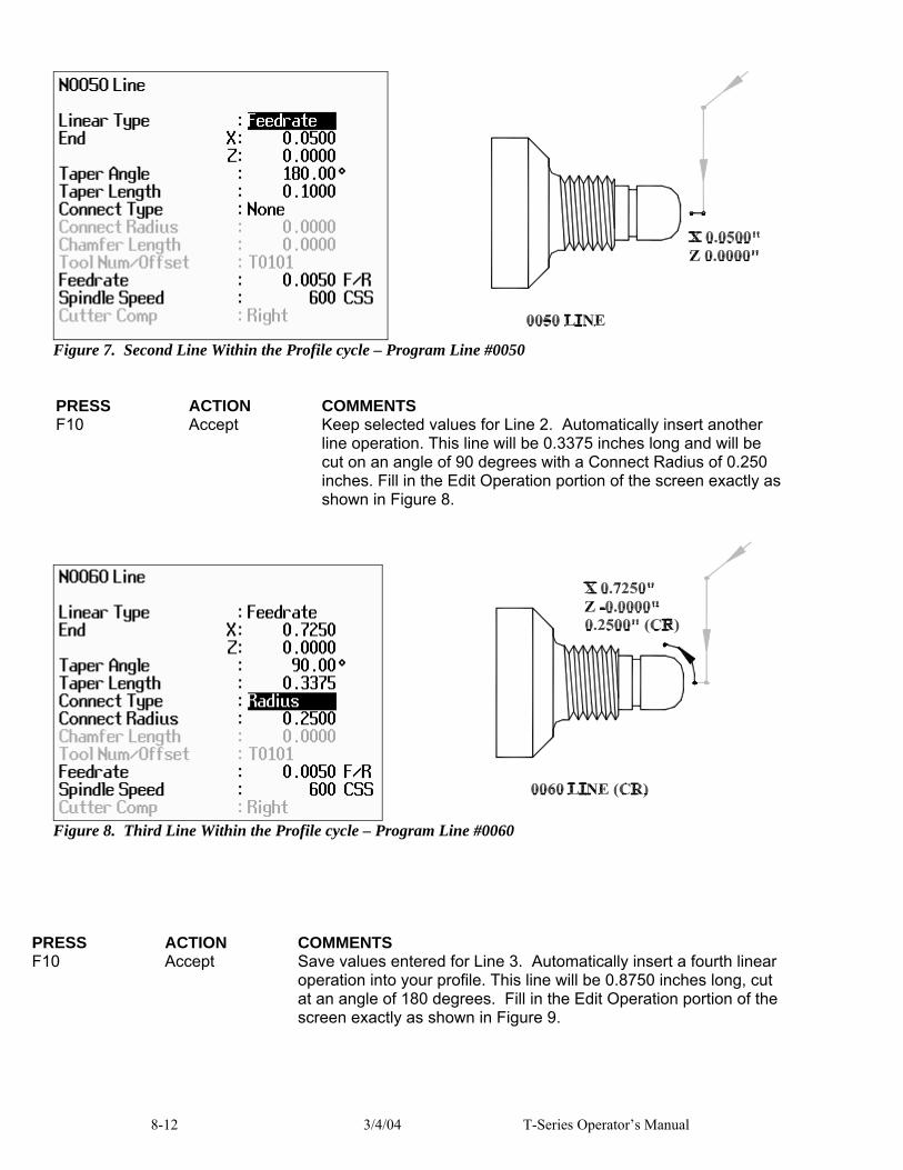
8-12 3/4/04 T-Series Operator’s Manual
Figure 7. Second Line Within the Profile cycle – Program Line #0050
PRESS ACTION COMMENTS F10 Accept Keep selected values for Line 2. Automatically insert another
line operation. This line will be 0.3375 inches long and will be cut on an angle of 90 degrees with a Connect Radius of 0.250 inches. Fill in the Edit Operation portion of the screen exactly as shown in Figure 8.
Figure 8. Third Line Within the Profile cycle – Program Line #0060
PRESS ACTION COMMENTS F10 Accept Save values entered for Line 3. Automatically insert a fourth linear
operation into your profile. This line will be 0.8750 inches long, cut at an angle of 180 degrees. Fill in the Edit Operation portion of the screen exactly as shown in Figure 9.

8-13 3/4/04 T-Series Operator’s Manual
Figure 9. Fourth Line Within the Profile cycle – Program Line #0070
PRESS ACTION COMMENTS F8 Graph Displays a preview of the part up to this point. Your graph should
look like that shown in Figure 10. ESC Escape Returns you to the Editing Menu F10 Accept Keeps selected values for Line 4. Automatically inserts a fifth linear
operation into your profile. This line will be 0.1350 inches long, cut at an angle of 90 degrees, with a blended chamfer connector 0.1” long. Fill in the Edit Operation portion of the screen exactly as shown in Figure 11.
Figure 10. Graph of Partial Profile

8-14 3/4/04 T-Series Operator’s Manual
Figure 11. Fifth Line Within the Profile cycle – Program Line #0080
PRESS ACTION COMMENTS F10 Accept Keep selected values for Line 5. Automatically insert a sixth linear
operation into your profile. This line will be 0.8750 inches long and will cut at an angle of 180 degrees with a connect Radius of 0.125 inches. Fill in the Edit Operation portion of the screen exactly as shown in Figure 12.
Figure 12. Sixth Line Within the Profile cycle – Program Line #0090
PRESS ACTION COMMENTS F10 Accept Keep selected values for Line 6. Automatically insert a seventh
linear operation into your profile. This line will be 0.2225 inches long and will cut at an angle of 90 degrees with a connect radius of 0.015 inches at the corner. Fill in the Edit Operation portion of the screen exactly as shown in Figure 13.

8-15 3/4/04 T-Series Operator’s Manual
Figure 13. Seventh Line Within the Profile cycle – Program Line #0100
PRESS ACTION COMMENTS F10 Accept Keep selected values for Line 7. Inserts an eighth linear operation
into your profile. This line will be 0.3889 inches long and will cut at an angle of 135 degrees, with a connect radius of 0.015 inches at the corner. Fill in the Edit Operation portion of the screen exactly as shown in Figure 14.
Figure 14. Eighth Line Within the Profile cycle – Program Line #0110
PRESS ACTION COMMENTS F10 Accept Keep selected values for Line 8. Inserts a ninth linear operation into
your profile. This line will be 0.625 inches long and will be cut at an angle of 180 degrees. Fill in the Edit Operation portion of the screen exactly as shown in Figure 15.
0110 LINE
X=1.990” Z=-2.025” 0.015” (CR)
0100 LINE
X=1.4400” Z=-1.7500” 0.1250” (CR)

8-16 3/4/04 T-Series Operator’s Manual
Figure 15. Ninth Line Within the Profile cycle – Program Line #0120
PRESS ACTION COMMENTS F8 Graph Displays a preview of the part up to this point. The profile to this
point should look like that shown in Figure 16. ESC Escape Returns you to the Editing Menu
Figure 16. Partial Graph of Profile Through Program Line #0120
0120 LINE

8-17 3/4/04 T-Series Operator’s Manual
PRESS ACTION COMMENTS F10 Accept Keep selected values for Line 9. Automatically inserts a tenth linear
operation. Esc Escape/Cancel Cancel tenth linear operation and return to profile edit menu. F3 Finish Inserts a finishing pass to remove any excess material left from the
Rough Pass, and leave a smooth finish. Fill in the Edit Operation portion of the screen exactly as shown in Figure 17.
● Note: If the depth of cut for X and Z are 0 or equal to the Depth of Cut in line # 0030 (X=0.01inches, and Z=0.005 inches), the finish pass will be cut in one pass
Figure 17. Finish Pass Within the Profile cycle – Program Line #0130.
PRESS ACTION COMMENTS F2 Tool Set the nose radius for Tool 2 = .0150, and the Nose Vector for Tool
2 = 3. Set the Spin Dir=CW, using the <space> bar to toggle thru the choices available.
F10 Accept Sets the Tool Library for Tool #2. F10 Accept Accepts Finish Pass values. Esc Escape Exits the profile edit menu.
D. Insert a Groove: PRESS ACTION COMMENTS F3 Insert Insert a new operation after the end of the profile. F8 Groove Creates an outside groove with a depth increment (X) of 0.05 inches
and a width increment (Z) of 0.025 inches, ending in a corner radius of 0.030 inches. Fill in the Edit Operation portion of the screen exactly as shown in Figure 18.
0130 FINISH PASS

8-18 3/4/04 T-Series Operator’s Manual
Figure 18. Grooving Operation – Program Line #0150.
PRESS ACTION COMMENTS F2 Tool Set the nose radius for Tool 3 = .0070, and the Nose Vector for Tool
3 = 8. Set the Spin Dir=CW, using the <space> bar to toggle thru the choices available. These same values can be set now for Tools 4 & 5, but be sure the cursor is back in the Tool 3 row before pressing F10!
F10 Accept Sets the Tool Library for Tools #3, 4, & 5. F8 Graph Displays a preview of the part up to this point. The part graph
should now look as shown in Figure 19.
Figure 19. Graph of Grooving Operation – Program Line #0150
PRESS ACTION COMMENTS
150 GROOVING
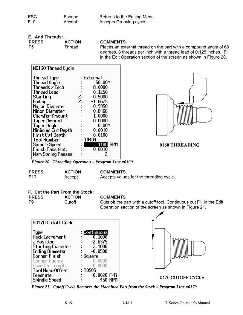
8-19 3/4/04 T-Series Operator’s Manual
ESC Escape Returns to the Editing Menu. F10 Accept Accepts Grooving cycle.
E. Add Threads: PRESS ACTION COMMENTS F5 Thread Places an external thread on the part with a compound angle of 60
degrees, 8 threads per inch with a thread lead of 0.125 inches. Fill in the Edit Operation section of the screen as shown in Figure 20.
Figure 20. Threading Operation – Program Line #0160.
PRESS ACTION COMMENTS F10 Accept Accepts values for the threading cycle.
F. Cut the Part From the Stock: PRESS ACTION COMMENTS F9 Cutoff Cuts off the part with a cutoff tool. Continuous cut Fill in the Edit
Operation section of the screen as shown in Figure 21.
Figure 21. Cutoff Cycle Removes the Machined Part from the Stock – Program Line #0170.
0160 THREADING
0170 CUTOFF CYCLE
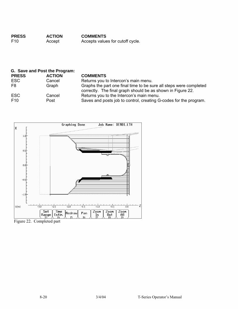
8-20 3/4/04 T-Series Operator’s Manual
PRESS ACTION COMMENTS F10 Accept Accepts values for cutoff cycle.
G. Save and Post the Program: PRESS ACTION COMMENTS ESC Cancel Returns you to Intercon’s main menu. F8 Graph Graphs the part one final time to be sure all steps were completed
correctly. The final graph should be as shown in Figure 22. ESC Cancel Returns you to the Intercon’s main menu. F10 Post Saves and posts job to control, creating G-codes for the program.
Figure 22. Completed part

T-Series Operator’s Manual 3/4/04 9-1
CHAPTER 9 CNC Program Codes
The next three chapters contain a description of the CNC program codes and parameters supported by the T-Series Control. The T-Series Control has some G codes and parameters that are modal, and some that are non-modal (one shot). The G codes and parameters that are modal will stay in effect until a new G code or parameter is issued. One shots are effective for the current line only. For example, a movement command of G01, which is modal, will remain in effect until a different movement command is issued, such as G00, G02, G03, etc.
Miscellaneous CNC Program Symbols
E, F - Feedrate or Thread Lead In threading mode (G32, G76 and G92), E and F can specify thread lead (in units/rev). In other modes, only F can be used to specify feedrate. Feedrate is either units/rev or units/min, depending on G98/G99 mode. The feedrate override knob can be used to modify the programmed feedrate (2% - 200%). The default feedrate is 3.0 units/minute. Example:
G01 X1.0 Z-2 F0.1 ; linear cut at X1 to Z-2 at 0.1 units/rev
N - Block Number Block numbers are used to identify CNC program lines. Block numbers are optional, but can be used with the Search Function (See Search option in Chapter 2) and make reading the NC files easier. Example:
N1 G56 M26/Z N2 G00 X0 Z0
O - Program Number The O program number allows you to identify your program with a certain number. If the program number is 9100-9999, the G codes from the O number through the next M99 will be extracted and placed in a separate subprogram/macro file. The lines will not be executed until the resulting file is called with M98 or G65. Example:
O1521 N1 G56 M26/Z N2 G00 X0 Z0
P - Parameter P can correspond to Dwell Time, subprogram number, or a general parameter in canned cycles. Examples:
G04 P1.32 ; Pause execution for 1.32 seconds G10 P73 R.1 ; Set parameter #73 (G73 retract) to .1 inches
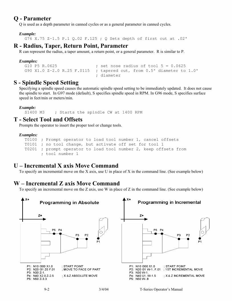
9-2 3/4/04 T-Series Operator’s Manual
Q - Parameter Q is used as a depth parameter in canned cycles or as a general parameter in canned cycles. Example:
G76 X.75 Z-1.5 P.1 Q.02 F.125 ; Q Sets depth of first cut at .02"
R - Radius, Taper, Return Point, Parameter R can represent the radius, a taper amount, a return point, or a general parameter. R is similar to P. Examples:
G10 P5 R.0625 ; set nose radius of tool 5 = 0.0625 G90 X1.0 Z-2.0 R.25 F.0115 ; tapered cut, from 0.5" diameter to 1.0" ; diameter
S - Spindle Speed Setting Specifying a spindle speed causes the automatic spindle speed setting to be immediately updated. It does not cause the spindle to start. In G97 mode (default), S specifies spindle speed in RPM. In G96 mode, S specifies surface speed in feet/min or meters/min. Example:
S1400 M3 ; Starts the spindle CW at 1400 RPM
T - Select Tool and Offsets Prompts the operator to insert the proper tool or change tools. Examples:
T0100 ; Prompt operator to load tool number 1, cancel offsets T0101 ; no tool change, but activate off set for tool 1 T0201 ; prompt operator to load tool number 2, keep offsets from ; tool number 1
U – Incremental X axis Move Command To specify an incremental move on the X axis, use U in place of X in the command line. (See example below)
W – Incremental Z axis Move Command To specify an incremental move on the Z axis, use W in place of Z in the command line. (See example below)

T-Series Operator’s Manual 3/4/04 9-3
: - Visible Comment Identifier
The colon (:) is used to indicate the start of a comment line within a CNC program. The colon must be the first character on the line. Examples:
: select work coordinate 3 G56 : rapid to part zero G00 X0 Z0 :Visible comments will be displayed on screen with the G-codes.
; - Internal Comment Identifier The semicolon (;) is used to indicate the start of an internal comment within a CNC program line. All characters after the semicolon are ignored when the program is run. Internal comments are used to document NC programs or temporarily omit the remainder of a line. Examples:
G56 ; select work coordinate 3 G00 ; G00 selected with no movement
[ ] – Numerical Expression The left bracket ‘[‘ and right bracket ‘]’ are used to delimit a numerical expression. Numerical expressions can contain floating point numbers or user and system variables in combination with mathematical operators and functions. The left parenthesis ‘(‘ or bracket ‘[‘ and right parenthesis ‘)’ or bracket ‘]’ can be used between the first left bracket and last right bracket to force operator precedence or associativity. A bracketed numerical expression can be used anywhere a number would be used. Comparison operators (‘eq’, ‘ne’, etc.) have built in rounding specified by parameter 144. Without this rounding, ‘eq’ would usually return “false” when comparing two numbers calculated in different ways. Comparison operators and logical operators (‘!’, ‘&&’, ‘||’) return 1.0 for “true” and 0.0 for “false”. The mathematical operators and functions are:
+ Addition (or unary positive) eq, == Equals - Subtraction (or unary negative) ne, != Not equals * Multiplication ge, >= Greater than or equals / Division gt, > Greater than ^ Exponentiation le, <= Less than or equals mod, % Modulo lt, < Less than abs Absolute value not, ! Logical not sin Sine (degrees) && Logical and cos Cosine (degrees) || Logical or tan Tangent (degrees) and Bit-wise and sqrt Square root xor Bit-wise exclusive or # Variable access or Bit-wise or ~ Bit-wise complement
Examples:
G91 X[13/64] Z[1+3/8] ; move the X axis 13/64 (0.2031) units ; and the Z axis 1 3/8 (1.375) units incrementally X[SQRT[ABS[SIN[#101]-COS[#102]]]] ; Move X as a function of #101 and #102
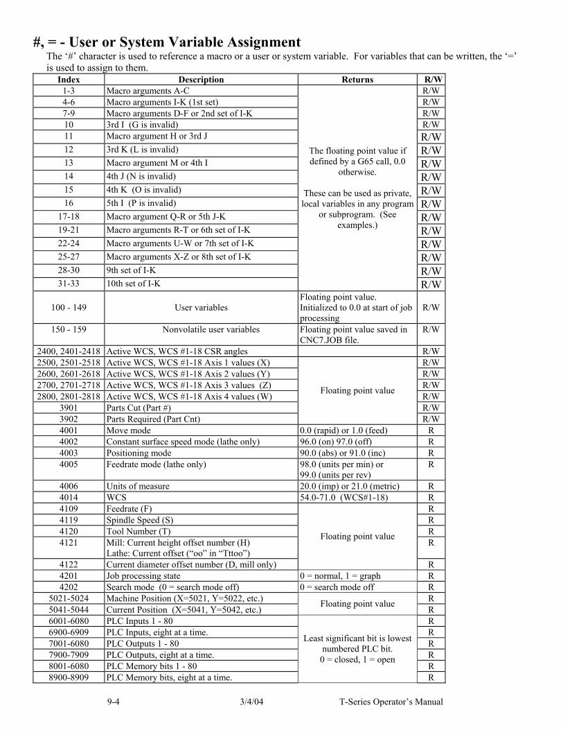
9-4 3/4/04 T-Series Operator’s Manual
#, = - User or System Variable Assignment The ‘#’ character is used to reference a macro or a user or system variable. For variables that can be written, the ‘=’ is used to assign to them.
Index Description Returns R/W 1-3 Macro arguments A-C R/W 4-6 Macro arguments I-K (1st set) R/W 7-9 Macro arguments D-F or 2nd set of I-K R/W 10 3rd I (G is invalid) R/W 11 Macro argument H or 3rd J R/W 12 3rd K (L is invalid) R/W 13 Macro argument M or 4th I R/W 14 4th J (N is invalid) R/W 15 4th K (O is invalid) R/W 16 5th I (P is invalid) R/W
17-18 Macro argument Q-R or 5th J-K R/W 19-21 Macro arguments R-T or 6th set of I-K R/W 22-24 Macro arguments U-W or 7th set of I-K R/W 25-27 Macro arguments X-Z or 8th set of I-K R/W 28-30 9th set of I-K R/W 31-33 10th set of I-K
The floating point value if defined by a G65 call, 0.0
otherwise.
These can be used as private, local variables in any program
or subprogram. (See examples.)
R/W
100 - 149
User variables
Floating point value. Initialized to 0.0 at start of job processing
R/W
150 - 159 Nonvolatile user variables Floating point value saved in CNC7.JOB file.
R/W
2400, 2401-2418 Active WCS, WCS #1-18 CSR angles R/W 2500, 2501-2518 Active WCS, WCS #1-18 Axis 1 values (X) R/W 2600, 2601-2618 Active WCS, WCS #1-18 Axis 2 values (Y) R/W 2700, 2701-2718 Active WCS, WCS #1-18 Axis 3 values (Z) R/W 2800, 2801-2818 Active WCS, WCS #1-18 Axis 4 values (W) R/W
3901 Parts Cut (Part #) R/W 3902 Parts Required (Part Cnt)
Floating point value
R/W 4001 Move mode 0.0 (rapid) or 1.0 (feed) R 4002 Constant surface speed mode (lathe only) 96.0 (on) 97.0 (off) R 4003 Positioning mode 90.0 (abs) or 91.0 (inc) R 4005 Feedrate mode (lathe only) 98.0 (units per min) or
99.0 (units per rev) R
4006 Units of measure 20.0 (imp) or 21.0 (metric) R 4014 WCS 54.0-71.0 (WCS#1-18) R 4109 Feedrate (F) R 4119 Spindle Speed (S) R 4120 Tool Number (T) R 4121 Mill: Current height offset number (H)
Lathe: Current offset (“oo” in “Tttoo”) R
4122 Current diameter offset number (D, mill only)
Floating point value
R 4201 Job processing state 0 = normal, 1 = graph R 4202 Search mode (0 = search mode off) 0 = search mode off R
5021-5024 Machine Position (X=5021, Y=5022, etc.) R 5041-5044 Current Position (X=5041, Y=5042, etc.)
Floating point value R
6001-6080 PLC Inputs 1 - 80 R 6900-6909 PLC Inputs, eight at a time. R 7001-6080 PLC Outputs 1 - 80 R 7900-7909 PLC Outputs, eight at a time. R 8001-6080 PLC Memory bits 1 - 80 R 8900-8909 PLC Memory bits, eight at a time.
Least significant bit is lowest numbered PLC bit.
0 = closed, 1 = open
R

T-Series Operator’s Manual 3/4/04 9-5
9000-9199 Parameter values 0 – 199 See Chapter 14. R
Index Description Returns R/W10000 Lathe: Tool X offset amount, current offset Floating point value R/W
10001-10099 Lathe: Tool X offset amount, offsets 01 - 99 Floating point value R/W11000 Lathe: Tool Z offset amount, current offset Floating point value R/W
11001-11099 Lathe: Tool Z offset amount, offsets 01 - 99 Floating point value R/W12000 Lathe: Tool nose radius, current offset Floating point value R/W
12001-12099 Lathe: Tool nose radius, offsets 01 - 99 Floating point value R/W13000 Lathe: Tool nose vector, current offset 1 - 9 R/W
13001-13099 Lathe: Tool nose vector, offsets 01 - 99 1 - 9 R/W14000 Lathe: Tool coolant, current tool 7, 8, 9 R/W
14001-14099 Lathe: Tool coolant, offsets 01 - 99 7, 8, 9 R/W15000 Lathe: Tool spindle direction, current offset 3, 4, 5 R/W
15001-15099 Lathe: Tool spindle direction, offsets 01 - 99 3, 4, 5 R/W16000 Lathe: Tool location, current offset Floating point value R/W
16001-16099 Lathe: Tool location, offsets 01 - 99 Floating point value R/W17000 Lathe: X wear adjustment, current offset Floating point value R/W
17001-17099 Lathe X wear adjustment, offsets 01 - 99 Floating point value R/W18000 Lathe: Z wear adjustment, current offset Floating point value R/W
18001-18099 Lathe: Z wear adjustment, offsets 01 - 99 Floating point value R/W19000 Lathe: nose radius wear adjustment, current offset Floating point value R/W
19001-19099 Lathe: nose radius wear adjustment, offsets 01 - 99 Floating point value R/W
Examples: #100 = #5041 ; set user variable #100 to the X axis current position G90 X[#5041+1+7/32] ; move the X axis 1 7/32 units (1.2188) incrementally #2501 = #5021 ; set WCS#1 X value to the current X position #2703=[#2703+1/8] ; add 1/8 units (.125) to the WCS#3 Z value ; Subroutine parameter and local variable access. G1 Z#A X#B F#F ; move to the coordinates passed as parameters #[Q] = #F * .10 ; Assign local variable #Q to 10% of #F #17 = #7 * .10 ; Same statement as previous using number references. #[C] = 0.05 ; Reassign #C. (Value passed as parameter is lost.)
Advanced Macro Statements (Optional) Warning: Branching and conditional execution are extremely powerful tools that, combined with access to system variables, allow you to do many things that would otherwise be impossible. Nevertheless, using branching and conditional execution can introduce undesirable and even unpredictable behavior into your programs. Undesirable effects can occur simply by graphing a program. The least of these undesirable effects could be entering an endless loop, failing to draw anything, or wiping out all the information in your tool library or WCS settings. It is your responsibility to make sure that undesirable things do not happen in your programs. You must monitor the job processing and search modes in your program, if necessary, and take appropriate action. Until you are confident of the actions of your program, you should step through it one block at a time to confirm your program logic.

9-6 3/4/04 T-Series Operator’s Manual
GOTO - Branch Execution To branch to another line within the same program or subprogram, use the statement GOTO <expression> where <expression> is any expression that evaluates to a valid block number in the program. GOTO causes an immediate branch to the specified destination. Program codes preceding a GOTO on the same line will be executed normally. Any program codes following GOTO on the same line will cause an error. If fast branching is disabled (parameter 145 = 0) then CNC7 searches forward in the program for the first matching block number and resumes searching, if necessary from the top of the program. For this reason when fast branching is disabled, backward branches take longer than forward branches and backward branch times depend on the total program size. If the program is sufficiently large, use of the GOTO statement could introduce temporary pauses. When fast branching is enabled (parameter 145 = 1) then CNC7 remembers the locations of block numbers as it finds them during program execution. Backward branches always take place immediately. The first forward branch to a block not yet encountered will take additional time as CNC7 searches forward for the block number; however, subsequent forward branches to that block number will take place immediately. The trade-off for using fast branching is that all line numbers at a given level of program or subprogram must be unique and programs will use more memory (approximately 16kilobytes of memory for every 1000 block numbers in the program.)
IF THEN ELSE - Conditional Execution Program symbols, G codes, M codes and GOTO commands may be executed conditionally using the IF statement. The general form of the IF statement is: IF <expression> THEN <execute if true> ELSE <execute if false> where <expression> is any valid expression, <execute if true> is one or more program codes to execute if <expression> evaluates to “true” (non-zero) and <execute if false> is one or more program codes to execute if <expression> evaluates to “false” (zero). All parts of the IF statement must appear on the same line. The “ELSE <execute if false>” part of the statement is optional and may be omitted. The “THEN” may be omitted; however, <expression> must be enclosed in brackets ([]). The IF statement may follow other program codes on the same line. Compound conditionals are possible but they cannot be nested. The first THEN always pairs with the first IF. ELSE always pairs with the first <expression> that evaluates to “false”. All program codes executed are executed as part of the same block. Examples:
; Branch to N200 if machine position is okay, otherwise go to N300 N100 IF #5041 LE 5.0 THEN GOTO 200 ELSE GOTO 300 ; Force subprogram parameter #D to be within range. IF [#D LE 0.005] #[D] = 0.005 ; Compound conditionals IF [#A LE 0.0] GOTO 100 ELSE IF [#A LE 2.5] GOTO 200 ELSE GOTO 300 IF [#A GE 0.0] IF [#D/#A GE 0.0] #[C] = SQRT[#D/#A]

T-Series Operator’s Manual 3/4/04 9-7
INPUT – Prompt Operator for Input The INPUT macro prompts the operator for numeric input. The general form of the INPUT statement is: INPUT “<prompt>” <variable> where <prompt> is the message prompt for the operator and <variable> is the variable in which to store the input. CNC7 will display a dialog with the given prompt and space for the operator response. The operator may enter any numeric expression (see above) including variables as a response. The operator must press CYCLE START or Alt-S to dismiss the dialog. Pressing Esc will cancel the job. CNC7 parses well ahead of the current execution to maximize throughput and efficiency. For this reason, an INPUT macro may prompt the operator for input immediately even though the INPUT macro is located in the middle or near the end of the job. (Use the “IF #6001” idiom to delay the prompt, if desired.) Parsing pauses while the dialog is displayed. Any statements parsed prior to the INPUT macro will have been queued and will continue to execute in the background while the prompt is displayed. Job processing will pause only if all queued statements have been executed before the operator supplies a response. INPUT macros will not graph. If you must graph the job, first set the input variable to a default value and use a conditional to execute the INPUT only if the job is being run normally. Use search mode cautiously with INPUT macros. To have search work properly, you may have to supply exactly the same input during the search as you did during the last actual run. Examples:
; Ask operator for pocket depth. Store result in #101 ; Note: this will not graph. INPUT “Enter pocket depth” #101 ; Allow job with INPUT statements to be graphed. #101 = 0.5 ; Supply a default value for graphing ; Ask for operator input only if not graphing. IF NOT #4201 THEN INPUT “Enter pocket depth” #101

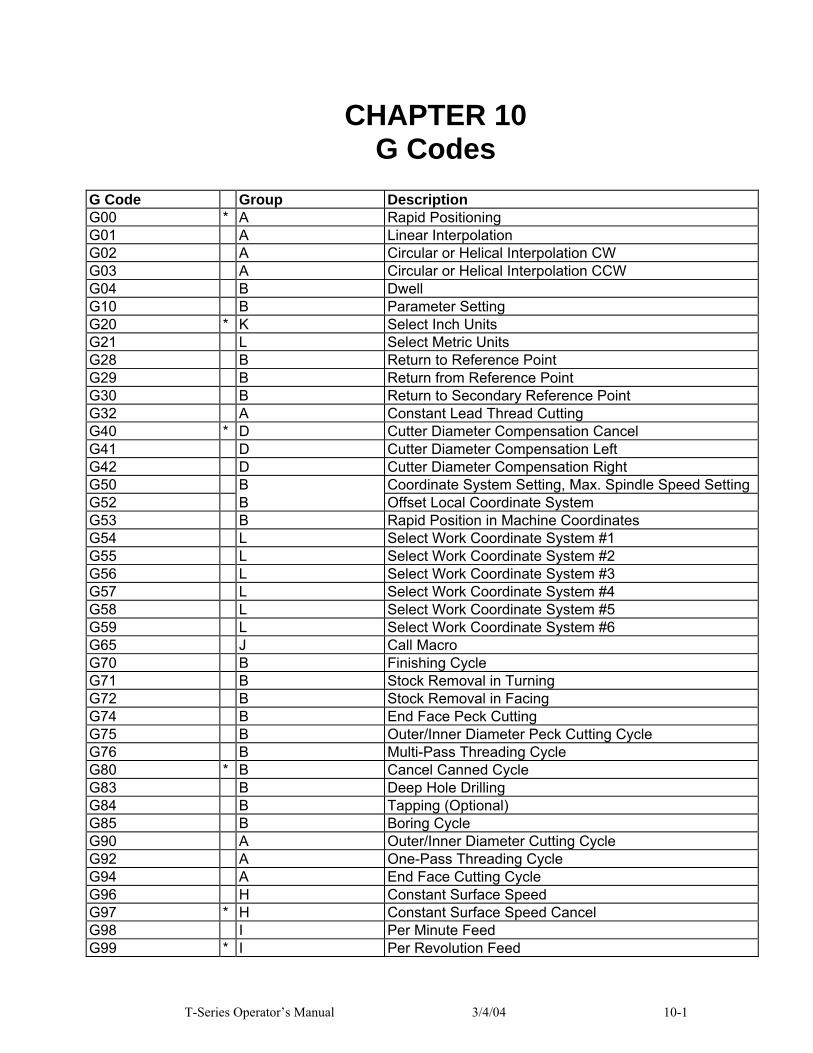
T-Series Operator’s Manual 3/4/04 10-1
CHAPTER 10 G Codes
G Code Group Description G00 * A Rapid Positioning G01 A Linear Interpolation G02 A Circular or Helical Interpolation CW G03 A Circular or Helical Interpolation CCW G04 B Dwell G10 B Parameter Setting G20 * K Select Inch Units G21 L Select Metric Units G28 B Return to Reference Point G29 B Return from Reference Point G30 B Return to Secondary Reference Point G32 A Constant Lead Thread Cutting G40 * D Cutter Diameter Compensation Cancel G41 D Cutter Diameter Compensation Left G42 D Cutter Diameter Compensation Right G50 B Coordinate System Setting, Max. Spindle Speed Setting G52 B Offset Local Coordinate System G53 B Rapid Position in Machine Coordinates G54 L Select Work Coordinate System #1 G55 L Select Work Coordinate System #2 G56 L Select Work Coordinate System #3 G57 L Select Work Coordinate System #4 G58 L Select Work Coordinate System #5 G59 L Select Work Coordinate System #6 G65 J Call Macro G70 B Finishing Cycle G71 B Stock Removal in Turning G72 B Stock Removal in Facing G74 B End Face Peck Cutting G75 B Outer/Inner Diameter Peck Cutting Cycle G76 B Multi-Pass Threading Cycle G80 * B Cancel Canned Cycle G83 B Deep Hole Drilling G84 B Tapping (Optional) G85 B Boring Cycle G90 A Outer/Inner Diameter Cutting Cycle G92 A One-Pass Threading Cycle G94 A End Face Cutting Cycle G96 H Constant Surface Speed G97 * H Constant Surface Speed Cancel G98 I Per Minute Feed G99 * I Per Revolution Feed

10-2 3/4/04 T-Series Operator’s Manual

T-Series Operator’s Manual 3/4/04 10-3
NOTES: ●All the default G Codes have been marked with the symbol " * ". ●A given line of a program may contain more than one G code. ●If several G codes from one group are used in the same line, only the G code specified last will remain active. ●G codes from group B are of "one shot" type (active only in the line in which they are specified). All other G codes are modal (active until another G code of the same group is specified).
G00 - Rapid Positioning G0 moves to the specified position at the maximum motor rate. The coordinates may be either absolute positions or incremental distances. G0 is modal and remains in effect until another positioning mode (G1, G2, G3 etc.) is commanded. G0 is the default-positioning mode. Example:
G0 X0.0 Z0.0
This command moves both X and Z to the absolute coordinate 0.0 at maximum feedrate. ● NOTE: G0 moves are only affected by the feedrate override knob if RAPID OVER button LED is ON.
G01 - Linear Interpolation G1 moves to the specified position at the programmed feedrate. The coordinates may be either absolute positions or incremental distances. The movement will be along a straight line. G1 is modal and remains in effect until another positioning mode (G0, G2, G3 etc.) is commanded. Example:
G01 X2 Z4 F10 G01 X6 Z3 F20
G02 & G03 - Circular Interpolation G2 moves in a clockwise circular motion, and G3 moves in a counterclockwise circular motion. The X or Z position specified in the G2 or G3 command is the end position of the arc, and may be an absolute position (X, Z) or an incremental distance (U, W). G2 and G3 are modal and remain in effect until another positioning mode (G0, G1, etc.) is commanded.
Circular motion can be programmed in two different ways: specifying the final point and the radius of the arc, or specifying the final point and the parameters I and K (center point of the arc as incremental values from the start position).

10-4 3/4/04 T-Series Operator’s Manual
METHOD 1: USING FINAL POINT AND RADIUS The commands G2 and G3 will have the following structure:
G2 Xx Zz Rr G3 Xx Zz Rr
where x and z will be the X and Z coordinates of the final point of the arc, and r will be the radius. Example:
G00 X2.0 Z1.0 ;rapid to start ;position X2, Z1 G02 X4.0 Z2.0 R1 ;arc to X4 Z2 with ;radius of 1
● WARNING: A lathe is not usually used to cut an arc larger than 90 degrees. With the use of special tools, a lathe can cut a 180-degree arc. This is the maximum value a lathe can cut an arc. Make sure the radius chosen follows the cutting ability of the lathe. METHOD 2: USING FINAL POINT AND PARAMETERS I & K
Another way to specify a circular operation is using the parameters I and K instead of the radius R. The parameters I and K are the incremental distances from the start point to the center of the arc. I = X center (radius) - X start (radius) K = Z center - Z start ● NOTE: X coordinates are diameter values, but I and R are always radius values. Example:
G00 X2.0 Z1.0 ;rapid to start ;pos. X2, Z0 G02 X4.0 Z2.0 K1 ;arc to X4 Z1 with radius 1
T-Series Operator’s Manual 3/4/04 10-5
G04 - Dwell G4 causes motion to stop for the specified time. The P parameter is used to specify the time in seconds to delay. G4 causes the block to decelerate to a full stop.
The minimum delay is 0.01 seconds and the maximum is 327.67 seconds. The dwell time is performed after all motion and M functions on the line. If the P parameter is not specified, X will be used instead. If neither P nor X is specified, the default dwell time of 0.01 seconds will be used. Example:
G0 X1 Z1 ; rapid to X1 Z1 G4 P2.51 ; pause for 2.51 seconds G0 X2 Z2 ; rapid to X2 Z2
G10 - Parameter Setting G10 allows you to set parameters for different program operations. Examples:
G10 P5 Z-1.1 ; Sets tool #5 z offset to -1.1 in the Offset Library G10 P5 X-1.3 ; Sets tool #5 x offset to -1.3 in the Offset Library G10 P5 R.25 ; Sets tool #5 nose radius to .25 in the Offset Library G10 P5 Q3 ; Sets tool #5 nose vector to 3 in the Offset Library G10 P1073 R.05 ; Sets machine parameter 73 to 0.05
G20 - Select Inch Units G20 selects inch units, affecting the interpretation of all subsequent dimensions and feedrates in the job file. G20 does not change the native machine units as set on the Control Configuration Menu.
G21 - Select Metric Units G21 selects metric units, affecting the interpretation of all subsequent dimensions and feedrates in the job file. G21 does not change the native machine units, as set on the Control Configuration Menu.
G28 - Return to Reference Point G28 moves to the first reference point, by way of an intermediate point. The location of the reference point, in machine coordinates, may be set in the Work Coordinate System Configuration menu. The intermediate point is specified in the local coordinate system, and may be at the current location (resulting in a move directly to the reference point). If an intermediate point is specified, only those axes for which positions are specified will be moved. If no axes are specified, all axes will be moved. The location of the intermediate point is stored for later use with G29. Examples:
G28 W0 ; move Z axis directly to reference point ; (X doesn't move) G28 U.5 W0 ; move X +.5, then move BOTH axes to ; reference point G28 X2 Z.1 ; move both axes to (2,0.1), then to ; reference point G28 ; move all axes to the reference point ; (no intermediate point)

10-6 3/4/04 T-Series Operator’s Manual
The G28 position is of great importance because it specifies the Tool Check position and the usual Tool Change position. The G28 position is the machine coordinate position that the machine will move to when the <TOOL CHECK> button is pressed. Also, the G28 position is the usual position at which tool changes occur during a job run.
G29 - Return from Reference Point G29 moves all axes to the intermediate point stored in a preceding G28 or G30 command. It may be used to return to the workpiece. If a position is specified, the machine will move to that position (in local coordinates) after reaching the intermediate point. G29 may only be specified after G28 or G30, though there may be intervening moves. Examples:
G29 ; move all axes back from reference point to ;intermediate point G29 X1 Z2 ; move all axes to intermediate point, then move to X1 Z2
G30 - Return to Secondary Reference Point G30 moves to a specified return reference point, by way of an intermediate point. The P parameter may be used to specify one of the 4 available Return Reference Points: The intermediate point is specified in the local coordinate system, and may be at the current location (resulting in a move directly to the reference point). If an intermediate point is specified, only those axes for which positions are specified will be moved. If no axes are specified, all axes will be moved. The location of the intermediate point is stored for later use with G29. The 4 available return reference points are defined in the Work Coordinate System Configuration menu. If you issue G30 without a P parameter, it functions exactly like G28, except that by default it uses the second reference return point. The following table shows how to issue G-codes to utilize the 4 available Return Reference Points:
Return Reference Point G-Code Equivalent Alternate G-Code Return #1 G28 G30 P1 Return #2 G30 G30 P2 Return #3 G30 P3 --- Return #4 G30 P4 ---
Examples:
G30 Z0 ; move Z axis directly to second reference point G30 P1 ; move all axes to first reference point
● NOTE: G30 P1 is equivalent to G28.
G32 - Constant Lead Thread Cutting G32 sets the constant lead thread cutting mode. During this mode, both axes are locked to the spindle encoder count. Once the encoder outputs a 1 turn signal, thread cutting is started at a fixed point so that the tool path remains unchanged for repeated thread cutting. Thread cutting follows the same tool path in rough cutting through finish cutting. ● NOTE: When G32 is used, X and Z indicate the endpoint of the cut and F indicates the lead. Example:
G00 X1.5 Z0.0 ; rapid move G32 X1.5 Z-2.0 F0.125 ; straight thread cut of 2 inches, lead of .125 ; or 8 threads per inch

T-Series Operator’s Manual 3/4/04 10-7
G40, G41, G42 –Cutter Diameter Compensation G41 and G42 in conjunction with the selected tool (T code) apply cutter compensation to the programmed tool path. G41 offsets the tool selected with the T code the amount of its nose radius, to the left of the workpiece, relative to the direction of travel. G42 offsets the tool selected with the T code the amount of its nose radius, to the right of the workpiece, relative to the direction of travel. G40 cancels G41 and G42. Example:
G41 T03 ; Tells the machine to compensate left the amount of the ; nose radius that corresponds to T03 in the Offset ; Library.
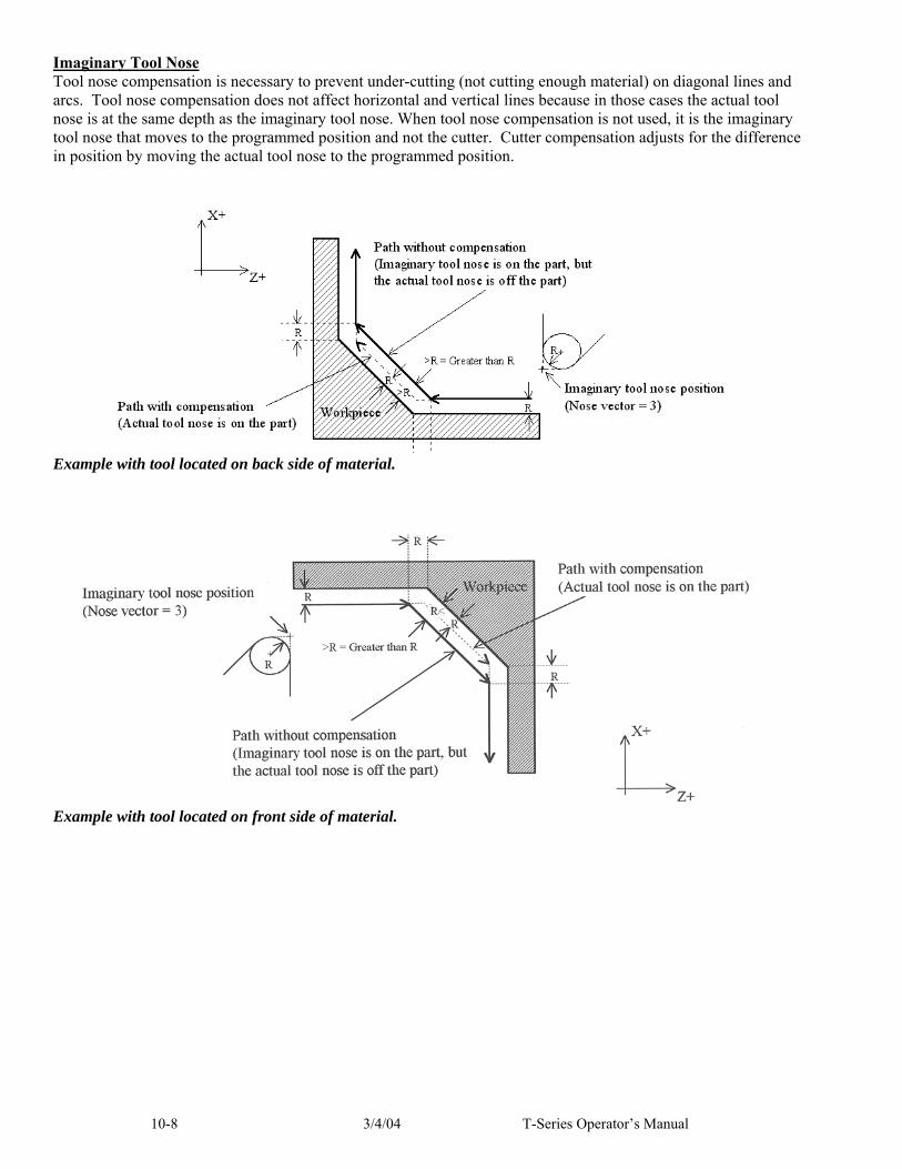
10-8 3/4/04 T-Series Operator’s Manual
Imaginary Tool Nose Tool nose compensation is necessary to prevent under-cutting (not cutting enough material) on diagonal lines and arcs. Tool nose compensation does not affect horizontal and vertical lines because in those cases the actual tool nose is at the same depth as the imaginary tool nose. When tool nose compensation is not used, it is the imaginary tool nose that moves to the programmed position and not the cutter. Cutter compensation adjusts for the difference in position by moving the actual tool nose to the programmed position.
Example with tool located on back side of material.
Example with tool located on front side of material.

T-Series Operator’s Manual 3/4/04 10-9
The direction of the imaginary tool nose is related to the nose vector or direction of the tool during cutting (see Chapter 3). The following drawings show the possible imaginary tool nose directions. Imaginary Tool Nose directions (tool located in back of material):
The tool nose compensation function (G41 or G42) should be in effect before the tool reaches the cutting start point.

10-10 3/4/04 T-Series Operator’s Manual
G50 -Coordinate System Setting or Maximum Spindle Speed for CSS mode
G50 has two functions depending on the supplied parameters: ● With axis parameters, G50 sets the current absolute position to the coordinates specified OR ● With the S parameter, G50 sets the maximum spindle speed when using constant surface speed (see G96 and G97). If you are using multiple work coordinate systems, positioning in all coordinate systems will be changed by the same amount (-4 in X, and +2 in Z in the example below). Examples:
G00 X5 Z-2 ; moves to the specified location G50 X1 Z0 ; sets the current position to the absolute position ; specified. G50 S2500 ; limit spindle to 2500 rpm in G96 mode, no matter how ; close X gets to 0.
G52 - Offset Local Coordinate System G52 shifts the local coordinate system origin by a specified distance. Multiple G52 codes are not cumulative; subsequent shifts replace earlier ones. The G52 shift may therefore be canceled by specifying a shift of zero. If you are using multiple coordinate systems, the G52 shift amount will affect all coordinate systems. Example:
G0 X0 Z0 ; move to origin M98 P9100 ; call subprogram G52 Z4 ; shift coordinate system 4 inches in Z G0 X0 Z0 ; move to new origin M98 P9100 ; call subprogram again with new coordinates G52 Z0 ; restore unshifted coordinate system
G53 - Rapid Positioning in Machine Coordinates G53 is a one-shot code that performs a rapid traverse using machine coordinates. It does not affect the current movement mode (G00-G03) or coordinate system (G54-G59). Example:
G53 X15 Z0 ; move to 15,0 in machine coordinates

T-Series Operator’s Manual 3/4/04 10-11
G54 - G59 - Select Work Coordinate System G54 through G59 select among the six regular work coordinate systems. After issuing the code, subsequent absolute positions will be interpreted in the new coordinate system. Example:
G54 G00 X0 Z0 ; select first WCS, move to origin G02 X1 Z-.5 R.5 ; cut something... G55 X1 Z1 ; select second WCS, move to 1,1
Using Extended Work Coordinate Systems: There are actually total of 18 workpiece origins. The extra workpiece origins are not accessible on the Work Coordinate Configuration menu; they can be set using Part Zero Menu. In a G-code program, the 12 additional workpiece origins may be selected by issuing “G54 P1” through “G54 P12”
Regular WCS Extended Work Coordinate Systems WCS G-Code WCS G-Code WCS G-Code WCS #1 G54 WCS #7 G54 P1 WCS #13 G54 P7 WCS #2 G55 WCS #8 G54 P2 WCS #14 G54 P8 WCS #3 G56 WCS #9 G54 P3 WCS #15 G54 P9 WCS #4 G57 WCS #10 G54 P4 WCS #16 G54 P10 WCS #5 G58 WCS #11 G54 P5 WCS #17 G54 P11 WCS #6 G59 WCS #12 G54 P6 WCS #18 G54 P12
G65 - Call Macro G65 calls a macro with user-specified values. A macro is a subprogram that executes a certain operation (e.g. linear cut, threading, etc.) with values assigned to variable parameters within the operation. Calling methods:
G65 Pxxxx Lrrrr Arguments or
G65 "program.CNC" Lrrrr Arguments where xxxx is the macro number (in file Oxxxx.CNC, 0000-9999 allowed, leading zeros required in filename), rrrr is the repeat value, "program.CNC" is the name of the macro file, and Arguments is a list of variable identifiers and values. Arguments to macro calls are specified by using letters A-Z, excluding G, L, N, O, and P. Macros are written just like normal programs. However, macro programs may access their arguments by using #A, #B, etc., or by using numbers: #1 for A, #2 for B, etc. (exceptions: #4-6 for I-K, #7-11 for D-H). Arguments I, J, and K can be used more than once in a macro call, with the first set of values stored as #4-6, the second as #7-9, etc., to a maximum of 10 sets. A macro can use the negative of an argument by placing a minus sign before the '#'. No other arithmetic operations are supported. Macros can call other macros (up to 4 levels of depth), Macro M-functions, and subprograms. Macro M-functions and subprograms can similarly call macros. Macros 9100 - 9999 may be embedded into a main program, using O91xx to designate the beginning of the macro and M99 to end it. CNC7 will read the macro and generate a file O91xx.CNC, but will not execute the macro. It will be executed when G65 is issued.

10-12 3/4/04 T-Series Operator’s Manual
Example 1: Main program:
G65 "TEST.CNC" A5 B3 Macro TEST.CNC:
G01 X#B Z-#A This call will produce
G01 X3 Z-5 Example 2: Main program:
G65 "TEST2.CNC" I3 J-5 K0.1 I2 J-2 I0 J0 Macro TEST2.CNC:
G01 X#4 Z#5 F#6 G01 X#7 Z#8 F#9 G01 X#10 Z#11 F#12
This call will produce
G01 X3 Z-5 F0.1 G01 X2 Z-2 G01 X0 Z0

T-Series Operator’s Manual 3/4/04 10-13
G70, G71, G72 - Stock Removal Cycles: General Cleanout cycles remove material from a work piece, leaving a desired contour. The cycle works with the profile you specify to generate the cleanout moves necessary. The G71 or G72 cleanout cycles can be used to generate rough contours. After either the G71 or G72 contour cleanout cycles are used, a G70 finish cycle can be used to produce a more smooth and accurate surface. Position requirements before start of cycle: ● Outer Diameter Cleanout - the tool's X-axis starting position must be larger than any point on the specified profile. ● Inner Diameter Cleanout - the tool's X-axis starting position must be smaller than any point on the specified profile. ● The X's start position must take into account U finish allowance Simulated jobs that violate position errors are displayed during backplot, but do not terminate. Jobs that violate position errors are displayed in the operator's message window and are terminated. If the profile's geometry begins with an arc, a rapid must precede the arc. The rapid actually does not take place. The G0's position is only used to define the starting point of the arc. If the profile's first segment is a rapid, the rough finish pass's first move will be a rapid. Cycle Operation: The cleanout cycle begins at the X-axis position prior to the start of the cycle. A rapid will be performed in the Z-axis to the starting Z-axis point of the profile if not already there. Once the cycle is finished, the tool is returned to the start of the profile. If U (W) and R-values are not specified in the G-code for the cycle, the values already stored in parameters 43, 44 will be used respectively. The start block value P must be less than the end block value Q. The N end block cannot contain feedrate without a move. The profile's start block must directly follow the clean out cycle G-codes. Several G-codes and M-codes are not allowed in the profile. These M codes are not allowed in the profile:
M2, M7, M8, M9, M10, M11, M26, M30, M50, M51, M91, M92, M102, M105, M106. These G codes are not allowed in the profile:
G7, G20-21, G28, G29, G30, G32, G50, G52, G53, G54-59, G70, G71, G72, G73, G75, G76, G90, G92, G93, G94.
If cutter compensation is to be used; the G41 or G42 must be turned on prior to the G71/G72 cycle. Finish allowance (U), depth of cut, and escape amounts are always treated as radius values.

10-14 3/4/04 T-Series Operator’s Manual
G71 - Stock Removal in Turning The G71 cycle removes stock in turning (see figure below). In the cycle, the tool starts at position 1 and cuts into the material with a linear move. In another linear move, the tool cuts through position 2. The tool then pulls back to position 3 and rapids back to position 1. This cutting cycle is repeated until the desired contour is achieved. The cycle can perform both inner and outer diameter cleanouts.
Modal values, such as feedrates, in the profile do not take effect in the G71 cycle. Cutter compensation can be used by the G71 cycle. The G71 has two forms: Parameter Setting:
G71 U_R_ U = depth of cut (radius amount); Parameter 43 R = escape amount (radius amount); Parameter 44 Cleanout with U and W:
G71 P_Q_U_W_F_S_T_ P = starting block number for profile Q = ending block number for profile U = finish allowance on X axis; see G70 W = finish allowance on Z axis; see G70 F = cutting feedrate (previous value if unspecified) S = spindle or surface speed (previous value if unspecified) T = tool number and/or offset (previous value if unspecified)

T-Series Operator’s Manual 3/4/04 10-15
Example 1 -G71 Outer Diameter Cleanout: G0 X4.5 Z0.4 ;Positioning tool before clean out cycle G71 U.1 R.2 G71 P1 Q8 U0.01 W0.005 N1 G0 X4 ;Start block - start of profile definition N2 G1 Z0 F.01 ;Second move of profile is Z move N3 G1 X4 Z-1 N4 G1 X3 Z-3 N5 G1 X3 Z-4 N6 G3 X4 Z-4.5 I0 K-.5 N7 G1 Z-5 ;End block - end of profile definition
The resulting contour is shown below:
Example 2 - G71 Inner Diameter Cleanout:
G0 X1 Z0.4 ;Positioning tool before clean out cycle G71 U.1 R.2 G71 P1 Q8 U0.01 W0.005 N1 G0 X4 ;Start block - start of profile definition N2 G1 Z0 F.01 ;Second move of profile if Z move N3 G1 X4 Z-1 N4 G1 X3 Z-3 N5 G1 X3 Z-4 N6 G1 x4 Z-5 ;End block - end of profile definition
The resulting contour is shown below.

10-16 3/4/04 T-Series Operator’s Manual
G72 - Stock Removal in Facing The G72 cycle removes stock in facing (see figure below). In the cycle, the tool starts at position 1. The tool cuts downward, in the negative X direction, using a linear move. The tool is then pulled back in the positive Z direction and rapids back in the positive X direction. The tool then moves to position 2 and proceeds to cut downward with a linear move. The cycle is repeated until the desired contour is achieved. The cycle can perform both outer and inner diameter cleanouts.
An escape move that would cause the tool to crash on the backside during a G72 cycle will not take place. Instead, the tool will rapid back with no escape amount. Modal values, such as feedrates, in the profile do not take effect during the G72 cycle. Cutter compensation can be used. The G72 has two forms: Parameter Setting:
G72 W_R_ W = depth of cut; parameter 43 R = escape amount; parameter 44 Clean out with U and W:
G72 P_Q_U_W_F_S_T_ P = starting block number for profile Q = ending block number for profile U = finishing allowance on X axis (radius) W = finishing allowance on Z axis (radius) F = cutting speedrate (previous value if unspecified) S = spindle or surface speed (previous value if unspecified) T = tool number and/or offset (previous value if unspecified)

T-Series Operator’s Manual 3/4/04 10-17
Examples 1 -G72 Outer Diameter Cleanout: G0 X4.5 Z0.4 ;Positioning tool before clean out cycle G72 U.1 R.2 G72 P1 Q8 U0.01 W0.005 N1 G0 X4 ;Start block - start of profile definition N1 G1 Z0 F.01 ;Second move in profile is Z move N2 G1 X4 Z-1 N3 G1 X3 Z-3 N4 G1 X3 Z-4 N5 G3 X4 Z-4.5 i0 k-.5 N6 G1 Z-5 ;End block - end of profile definition
The resulting contour is shown below:
Example 2 - G72 Inner Diameter Cleanout:
G0 X1 Z0.4 ;Positioning tool before cleanout cycle G72 U.1 R.2 G72 P1 Q8 U0.01 W0.005 N1 G0 X4 ;Start block - start of profile definition N2 G1 Z0 F.01 ;Second move in profile is Z move N3 G1 X4 Z-1 N4 G1 X3 Z-3 N5 G1 X3 Z-4 N6 G1 x4 Z-5 ;End block - end of profile definition
The resulting contour is shown below:

10-18 3/4/04 T-Series Operator’s Manual
G70 - Finishing Cycle The G70 finishing cycle is used in conjunction with a G71 or G72 roughing cycle. The G70 cycle removes material purposely left by the roughing cycle. A different feedrate and tool can be used to follow the exact contour of the workpiece during the finishing cycle. Cutter compensation can be used with the finish pass. The type of compensation used should match the cleanout cycles. The G41/G42 must appear before the G70 cycle is called. The start and end block of the finish cycle do not need to match the G71/G72 profile. If the user picks block with in the start and end block, the finish pass will only pass the tool over the picked block's surface. Multiple finish pass cycles can be performed on a cleaned out contour. For each cycle, multiple passes can be made. All modal values specified in the profile will take effect when the tool passes over the modal's corresponding position. If more than one pass is made, the modal values are reset for each pass to their previous values before G70 was installed. G70 finish pass P and Q block values can only reference the previously executed cleanout profile. The G70 cycle has two forms: Finishing with no offset:
G70 P_Q_ P = starting block number for profile Q = ending block number for profile Finishing with U and W offsets:
G70 P_Q_U_W_ P = starting block number for profile Q = ending block number for profile U = finish allowance on X axis W = finish allowance on Z axis The cycle uses one or more passes along the profile. The number of passes is determined by the greater of:
G71/G72 allowance W OR G71/G72 allowance U G70 allowance W G70 allowance U

T-Series Operator’s Manual 3/4/04 10-19
Examples of obtaining the desired number of finish passes: Roughing cycle specification: G71 U allowance = 0.02 G71 W allowance = 0.02 For 1 finish pass: G70 U allowance = 0.02 or G70 allowance = 0.0 G70 W allowance = 0.02 G70 allowance = 0.0 For 2 finishing passes: G70 U allowance = 0.02 G70 W allowance = 0.01 For n finishing passes (each pass removes n amount of material) G70 U allowance = G71 allowance U/n G70 W allowance = G71 allowance W/n Example: G71 Outer Diameter cutout with one finish pass:
G0 X1 Z6 ; positioning of the tool before cleanout cycle G71 U.1 R.2 G71 P1 Q6 U0.010 W0.005 N1 G0 X4 ; start block - start of profile definition N2 G1 Z-1 F.01 ; Second move in profile is Z move N3 G1 X4 Z-2 N4 G1 X3 Z-4 N5 G1 X3 Z-5 N6 G3 X4 Z-5.5 I0 K-.5 N7 G1 Z-6 ; end block - end of profile definition G70 P1 Q6 U0.005 W0.005 ; finish pass
The resulting contour is shown below.

10-20 3/4/04 T-Series Operator’s Manual
G74 - End Face Peck Cutting Cycle G74 sets the end face peck cutting cycle (chip breaking). If X remains constant at 0 and Z is the only moving axis, then the peck cutting operation will be similar to the peck drilling operation on a mill. If X moves, grooves will be cut with the Z-axis breaking the chips
The basic format of the end face peck cutting cycle is as follows:
G74 Rr1 G74 Xx Zz Pp Qq Rr Ff
Where: r1: escape/retract amount. This is a modal value and it is not changed until another value is entered. This value can also be specified in parameter 44 (see Chapter 14). x: X value of the end point. z: Z value (total depth) of the end point. p: X-axis relief amount (radial). This value can be specified in parameter 45 (see Chapter 14). q: depth of cut. This value can be specified in parameter 43 (see Chapter 14). r: X-axis relief amount. This value can be specified in parameter 46 (see Chapter 14). f: feedrate. ● NOTE: In incremental mode X and Z are replaced by U and W, respectively. Also, even though R is used to specify both ' r1' and ' r ', their functions are specified by the presence of X or U. When X or U is specified, ' r ' is used.

T-Series Operator’s Manual 3/4/04 10-21
Example 2 (X>0): G00 X1 Z0 ; rapid move G74 X1.5 Z-1.5 P0.05 Q0.1 R0.03 F.1 ; peck cut groove to X1.5 to a Z depth of 1.5 at an increment ; of 0.1, moving in X at 0.05 increments with relief amount of ; 0.03 at the cutting bottom at a feedrate of 0.1.
Example 1 (at X0):
G00 X0 Z0 ; rapid move G74 R0.05 ; peck drilling escape/retract amount of 0.05 ;(this is a modal value and is not changed ;until another value is entered) G74 Z-1.5 Q0.2 F0.1 ; peck drill hole at X0 to a Z depth of 1.5 at ; an increment of 0.2, at a feedrate 0.1.

10-22 3/4/04 T-Series Operator’s Manual
G75 - Outside/Inside Diameter Peck Cutting Cycle G75 selects the outer/inner diameter peck cutting cycle. The basic format of the outside/inside diameter peck cutting cycle is as follows:
G75 Rr1 G75 Xx Zz Pp Qq Rr Ff
Where: r1: retract amount. This is a modal value and it is not changed until another value is entered. This value can also be specified in Parameter 44. x: X value (total depth) of the end point. z: Z value of the end point. p: Z-axis step amount. This value can also be specified in parameter 45. q: depth of cut. This value can also be specified in parameter 43. r: Z-axis relief amount. This value can also be specified in parameter 46. f: feedrate. Example with Z step and Z relief amounts:
G00 X3 Z-3 ; rapid move G75 R0.05 ; retract amount of 0.05 (this value is modal and ; is not changed until another value is entered) G75 X0.5 Z-5 P0.2 Q0.1 R0.05 F.01 ; peck cut inner diameter of 0.5 to a length of 2 ; inches at an increment of 0.2, moving in x at ; 0.1 increments, relief amount of 0.05 at the ; bottom of cut at a feedrate of 0.01.

T-Series Operator’s Manual 3/4/04 10-23
Example of Peck Cutting with no Z movement: G00 X3 Z-3 : rapid move G75 R0.05 ; retract amount of 0.05 (this is a modal value ; and is not changed until another value is ; entered) G75 X0.5 Q0.1 F0.01 ; cut inner diameter of 1 at an increment of ; 0.1, feedrate of 0.01.

10-24 3/4/04 T-Series Operator’s Manual
G76 - Multi-Pass Threading Cycle G76 sets the multi-pass threading cycle command. In this cycle, threading is performed in increments to a specified depth.
The basic format for this cycle is as follows:
G76 Pmmrraa Qqmin Rqmax G76 Xx Zz Rr Pp Qq Ff
Where, P: mm: finish count. Can be specified by parameter 50 (see Chapter 14). rr : chamfering amount. Can be specified by parameter 49 (see Chapter 14). aa : thread compound angle. Can be specified by parameter 51 (see Chapter 14). Q: qmin: minimum cutting depth. Can be specified by parameter 52 (see Chapter 14). R: qmax: finish allowance. Can be specified by parameter 53 (see Chapter 14). R: r: taper radius amount. If 0, straight multi-pass threading will be performed. P: p: thread height Q: q: cutting depth in first cut F: f: thread lead (same as in G32) Example:
G00 X4 Z3 ; rapid move G76 P011055 Q0.05 R0.1 ; setting parameters G76 X2 Z0 R0 P0.5 Q0.1 F0.1 ; multi-pass threading of ; 3 inches in length, ; thread height of 0.5 and ; minor diameter of 2 inches, ; lead of 0.1 and first cut ; depth of 0.1.
● NOTE: The first G76 line, without X and/or Z is optional. Without them, the values previously stored in the parameters will be used.

T-Series Operator’s Manual 3/4/04 10-25
G80 – Canned Cycle Cancel G80 is used to cancel a canned cycle once the operation has been performed.
G83 – Deep Hole Drilling G83 is a deep hole drilling cycle. It periodically retracts the tool to the surface to clear accumulated chips, then returns to resume drilling where it left off. The retract and return are performed at a rapid rate. Because there may be chips in the bottom of the hole, the tool does not return all the way to the bottom at the rapid rate. It slows down to federate a short distance above the bottom. This clearance distance is selected by setting parameter 83 with G10 (see example below). Example:
G10 P83 R.05 ; set clearance to .05” G83 X0 R.1 Z-2 Q.5 ; drill 2” deep hole in 0.5” steps
G84 – Tapping (Optional)
G84 performs right-hand tapping. The spindle speed and federate should be set and the spindle started in the CW direction before issuing G84. By default, G84 uses M4 to select spindle CCW (at the bottom of the hole) and M3 to re-select spindle CW (after backing out of the hole). Alternate M functions may be specified by setting parameters 74 (for CCW) and 84 (for CW). See G10 for examples. The tap will continue to cut a short distance beyond the programmed Z height as the spindle comes to a stop before reversing. When tapping blind holes, be sure to specify a Z height slightly above the bottom of the hole to prevent the tool from reaching bottom before the spindle stops. The exact distance you must allow will depend on your machine and the diameter and pitch of the tapping tool.
G85 – Boring Cycle G85 is used to bore a hole so that a smooth finish may be acquired. The tool will feed into depth at the specified federate and retract back out at the same federate.

10-26 3/4/04 T-Series Operator’s Manual
G90 - Outside/Inside Diameter Cutting Cycle G90 sets the outer/inner diameter cutting cycle command. These diameters can be specified along straight cuts or diagonal/taper cuts. In incremental programming, the signs of U and W will depend on the direction of the toolpath when approaching the workpiece. That is, if the cutter moves in the negative X direction, then the value of U will be negative. Straight Cutting In this cycle, the cutter moves to the diameter indicated by X and cuts in a straight line to the depth or length indicated by Z. In the example at the right, the cutter first rapids to the start point located at X2.5Z-1, then rapids down to X1.5 at the same Z, and then cuts at the specified feedrate to Z-4. At Z-4, the cutter then moves back to X2.5 at the same feedrate and returns to the start point. Example:
G00 X2.5 Z-1.0 G90 X1.5 Z-4.0 F0.5
Taper Cutting In this cycle, the cutter cuts diagonally to the diameter and depth indicated by X and Z, respectively. The value of R will dictate the value of the starting diameter. A negative R will make the ending diameter equal to X and the starting diameter equal to X minus twice the absolute value of R. A positive R will make the ending diameter equal to X and the starting diameter equal to X plus twice the value of R. first rapids to the start point located at X2.5Z-1, then rapids down to X1.0, the smaller diameter, at the same Z, and then cuts at the specified feedrate to Z-4. At Z-4 the value of the larger diameter is 1.5. Next, the cutter then moves back to X2.5 at the same feedrate and returns to the start point. Example:
G00 X2.5 Z-1.0 G90 X1.5 Z-4.0 R-0.25 F0.5

T-Series Operator’s Manual 3/4/04 10-27
The following table shows the relationship between the tool paths and the signs of U, W, and R during incremental programming when performing taper cutting.
G92 - Thread Cutting Cycle G92 sets the thread cutting cycle command. This cycle can be specified for straight thread cutting or taper thread cutting. In incremental programming, the signs of U and W will depend on the direction of the tool path when approaching the workpiece. That is, if the cutter moves in the negative X direction, then the value of U will be negative.
G92 is similar to G32 in that X and Z indicate the endpoint of the cut and F indicates the thread lead. The chamfering amount, rr, which is selected by parameter 49 (see Chapter 14), is a multiplier of the thread lead. That is, the chamfer distance is rr times the thread lead.

10-28 3/4/04 T-Series Operator’s Manual
Straight Thread Cutting In this cycle, the cutter moves to the diameter indicated by X and threads in a straight line to the depth or length indicated by Z. In the example below, the cutter first rapids to the start point located at X2.5Z-1, then rapids down to X2 at the same Z, and then cuts with the specified lead to Z-3. At Z-3, the cutter pulls out of the part the amount of the chamfering distance, then rapids back up to X2.5 and returns to the start point. Example:
G00 X2.5 Z-1.0 G92 X2.0 Z-3.0 F.1
Taper Thread Cutting In this cycle, the cutter threads diagonally to the diameter and depth indicated by X and Z, respectively. The value of R will dictate the value of the starting diameters. A negative R will make the ending diameter equal to X and the starting diameter equal to X minus twice the absolute value of R. A positive R will make the ending diameter equal to X and the starting diameter equal to X plus twice the value of R.
In the example below, the cutter first rapids to the start point located at X3.5 Z-1, then rapids down to X2.5, the inner diameter, at the same Z, and then cuts with the specified lead to Z-3. At Z-3 the value of the outer diameter is 2.5 and the cutter pulls out of the part the amount of the chamfering distance, then rapids back up to X2.5 and returns to the start point. Example:
G00 X3.5 Z-1.0 G92 X2.5 Z-3.0 R-0.25 F.1
Multiple thread leads This is done by using the formula: 2nd – nth thread lead start point = previous thread lead start point + ((1/TPI) / # of leads) Example: We want to produce a triple lead thread with a thread lead of 10 threads per inch (TPI). The start point for the first thread lead is 0.1000 from the face of the material being threaded. Thread lead # 1 start point = 0.1000. Thread lead # 2 start point = 0.1000 + ((1/10)/3) = 0.1333. Thread lead # 3 start point = 0.1333 + ((1/10)/3) = 0.1666.

T-Series Operator’s Manual 3/4/04 10-29
G94 - End Face Turning G94 sets the end face turning cycle command. This cycle can be specified for straight face turning or taper face turning. In incremental programming, the signs of U and W will depend on the direction of the toolpath when approaching the workpiece. That is, if the cutter moves in the negative X direction, then the value of U will be negative.
Straight Face Turning In this cycle, the cutter moves to the depth indicated by Z and then cuts to the diameter indicated by X. In the example below, the cutter first rapids to the start point located at X2Z-1, then rapids to Z-1.25 at the same X, and then cuts at the specified feedrate to X1. At X1, the cutter then moves back to Z-1 at the same feedrate and rapids back up to the start point. Example:
G00 X2.0 Z-1.0 G94 X1.0 Z-1.25 F0.1
Taper Face Turning In this cycle, the cutter cuts diagonally to the diameter and depth indicated by X and Z, respectively. The value of R will dictate the approach of the cutter to the specified Z coordinate, that is, the value of R will determine how much the cutter will stop short (positive R) or pass (negative R) Z before cutting diagonally down to the specified diameter. In the example below the value of R is negative, thus, the cutter first rapids to the start point located at X2Z-1, then rapids to Z-1.5 at the same X, and then cuts diagonally down to X1 at the specified feedrate. At X1, the value of Z is -1.25, then the cutter moves back to Z-1 at the same feedrate and rapids back up to the start point. Example:
G00 X2.0 Z-1.0 G94 X1.0 Z-1.25 R-0.25 F0.1

10-30 3/4/04 T-Series Operator’s Manual
The following table shows the relationship between the tool paths and the signs of U, W, and R during incremental programming when performing taper face turning.
G96 & G97 - Constant Surface Speed Control & Cancel G96 sets the mode for constant surface speed control in feet/min (sfm) or meters/min. S values are assumed as surface speed. When CSS is active, the spindle speed changes as the X position changes, to maintain a constant linear velocity at the tool tip. No matter how close X gets to X0, the spindle speed will not exceed the speed set with G50 or the machine's maximum spindle speed, whichever is less. G97 cancels the constant surface speed control.
G96 S800 ; sets constant surface speed to 800 feet/min G01 X1 Z-3 F0.1 G97 S1200 ; cancels constant surface speed and sets ; spindle speed to 1200 rpm
G98 - Feed per minute G98 sets the cutting feedrate mode in units/minute. There are no associated parameters.
G99 - Feed per revolution G99 sets the cutting feedrate mode in units/rev. There are no associated parameters.

T-Series Operator’s Manual 3/4/04 11-1
CHAPTER 11 M-functions
M-functions are used to perform specialized actions in CNC programs. Most of the T-series Control M-functions have default actions, but they can be customized with the use of macro files. Certain restrictions apply to calling M functions: ● Only one M-function per program line is permitted. ● M-functions are not allowed on the same line as a tool change (see T in Chapter 9).
Macro M-functions Macro M functions are M functions that have been customized with a macro file. The T-Series CNC M-functions from 0 through 90 can be fully customized. No M-functions above 90 may be customized with macros. The default action listed will be performed unless that M-function has been customized. To create a macro for an M-function, a file must be created in the C:\CNC7T directory. The file's name must be CNC7.Mxx where xx is the M-function number used to call the macro. M-functions 0-9 must use single digits in the filename (e.g. use M3, not M03). The contents of the file may be any valid M and G-codes. The following is an example macro M-Function to turn on spindle with variable frequency drive and wait for "at speed" response.
M94/1 ; request spindle start M101/5 ; wait for up to speed signal
These lines would be placed in the file C:\CNC7T\CNC7.M3. Each time the M-function is encountered in a program, the macro file will be processed line by line. ● NOTE: Nesting of macro M-functions is allowed, but, recursive calls are not. If a macro M-function does call itself, the default action of the function will be executed. ● NOTE: The M and G-codes within a macro M-function are not usually displayed on the screen as they are executed, and are all treated as one operation in block mode. If you wish to see or step through macro M-functions (e.g. for testing purposes), see Machine Parameter 10 in Chapter 14 ● NOTE: The CNC7.TCH file, which contains the G-code sequence for doing a customized tool change, is also considered to be an M-function Macro so that its behavior can be modified by Machine Parameter 10.
M00 - Stop For Operator Motion stops and the operator is prompted to press the CYCLE START button to continue. Default action:
M100/75
M01 - Optional Stop for Operator M1 has no effect unless optional stops are turned on. When optional stops are on, M1 is identical to M0. Default action:
M100/75 ; if optional stops are turned on.

11-2 3/4/04 T-Series Operator’s Manual
M02 - Restart Program Restarts the program from the first line. The operator is prompted to press the CYCLE START button to continue.
M03 - Spindle On Clockwise M3 requests the PLC to start the spindle in the clockwise direction. Default action:
M95/2 M94/1
M04 - Spindle On Counterclockwise M4 requests the PLC to start the spindle in the counterclockwise direction. Default action:
M95/1 M94/2
M05 - Spindle Stop M5 requests the PLC to stop the spindle. Default action:
M95/1/2
M07 - Mist Coolant On M7 causes the PLC to start the mist coolant system. Default action:
M95/3 M94/5
M08 - Flood Coolant On M8 causes the PLC to start the flood coolant system. Default action:
M95/5 M94/3
M09 - Coolant Off M9 causes the PLC to stop the coolant system. Default action:
M95/3/5
M10 - Clamp On M10 causes the PLC to activate the clamp. Default action:
M94/4
M11 - Clamp Off M11 causes the PLC to release the clamp. Default action:
M95/4

T-Series Operator’s Manual 3/4/04 11-3
M26 - Set Axis Home M26 sets the machine home position for the specified axis to the current position (after the line's movement). Example:
M92/X ; home X axis to plus home switch M26/X ; set machine home for X-axis there M91/Z ; home Z-axis to minus home switch M26/Z ; set machine home for Z-axis there
M29- Set Tap Mode for G84 M29 sets the tap mode for G84; either right-hand or left-hand tapping. Right-hand tap mode is the initial default at job start-up. If Left-hand tap mode is required, M29 and P1 need to be specified on the same line.
Tap Mode Command CW ( Right-hand ) M29 CCW ( Left-hand ) M29 P1
M50 – C Axis Disable M50 is the command to disable the C axis and it is a locked software option. When the C axis is disabled, no axis label will be present on the screen and the encoder information for the C axis is ignored. In order for the M50 command to work, the 3rd or 4th axis label must be set to ‘C’ with the associated parameter (93 for 3rd axis and 94 for 4th axis) set for C axis operation. In practical applications, the default behavior for the M50 command is usually modified using a custom CNC7.M50 program. Example CNC7.M50:
M95/9 ; Switch to speed mode M50 ; Perform the default actions for C axis disable
M51 – C Axis Enable M51 is the command to enable the C axis and it is also locked as a software option.. When C axis is enabled, the C axis label will be present on the DRO and encoder information for the C axis is used to determine the position of the C axis. In order for the M51 command to work, the 3rd or 4th axis label must be set to ‘C’ with the associated parameter (93 for 3rd axis and 94 for 4th axis) set for C axis operation. In practical applications, the default behavior for the M51 command is modified using a custom CNC7.M51 program to ensure that the spindle has stopped before the C axis is enabled. Example CNC7.M51:
G97 ; Turn off CSS (constant surface speed) M3 S0 ; Turn off spindle M101/9 ; Wait for zero speed signal form inverter on INP9 M94/9 ; Switch to torque mode M51 ; Perform the default actions for C axis enable M151 ; Unwind C-axis position
Note in the above examples for M50 and M51 where the M95/9 (turn off INP41) and M94/9 (turn on INP41) commands are used, it is assumed that the plc program, conditioned upon the state of INP41, has been modified to output the appropriate hardware signals required to switch between speed and torque mode.
M91 - Move to Minus Home M91 moves to the minus home switch of the axis specified at the slow jog rate for that axis. After the minus home switch is reached, the tool is moved back until the home switch untrips. Then the next encoder index pulse is reached. Example:
M91/Z ; move the Z-axis to the minus home switch. G50 Z-10 ; sets Z minus home switch at -10

11-4 3/4/04 T-Series Operator’s Manual
M92 - Move to Plus Home M92 moves to the plus home switch of the axis specified at the slow jog rate for that axis. After the plus home switch is reached, the tool is moved back until the home switch untrips. Then the next encoder index pulse is reached. Example:
M92/X ; moves the X-axis to the plus home switch. G50 X+10 ; Sets X plus home switch at +10
M93 - Release Motor Power M93 releases the motor power for the axis specified. If no axis is specified, then all axes are released. Example:
M93/X ; releases the X-axis. M93 ; releases the motors on all axes.
● NOTE: Any axis freed within a CNC program should not be used in that program afterwards. Incorrect positioning may result.
M94/M95 - Output On/Off There are sixteen user definable M-function requests. M94 and M95 are used to request those inputs to turn on or off respectively. M-function requests 1-16 are mapped to the PLC as inputs 33 - 48, as shown in the following table:
On Off PLC Input On Off PLC Input M94/1 M95/1 33 M94/9 M95/9 41 M94/2 M95/2 34 M94/10 M95/10 42 M94/3 M95/3 35 M94/11 M95/11 43 M94/4 M95/4 36 M94/12 M95/12 44 M94/5 M95/5 37 M94/13 M95/13 45 M94/6 M95/6 38 M94/14 M95/14 46 M94/7 M95/7 39 M94/15 M95/15 47 M94/8 M95/8 40 M94/16 M95/16 48
M-function request to PLC Input map To use M94 and M95 to control a function external to the servo control, such as an indexer, the input request must be mapped to one of the PLC outputs in the PLC program. See M94/M95 function usage in the PLC section of the service manual. Example:
M94/5/6 ; turns on output requests 5 and 6. ● NOTE: Requests 1, 2, 3, 4 and 5 are by default used to control the spindle CW, spindle CCW, flood coolant, clamp, and mist coolant. ● NOTE: The request number need not be (and generally is not) the same as the M-function number or the PLC output number. For example, M3 turns on output request #1 (PLC Input #33), which may activate PLC output #14.
M98 - Call Subprogram M98 calls a user-specified subprogram. A subprogram is a separate program that can be used to perform a certain operation (e.g. a drilling pattern, contour, etc.) many times throughout a main program. Calling methods:

T-Series Operator’s Manual 3/4/04 11-5
M98 Pxxxx Lrrrr or
M98 "program.cnc" Lrrrr Where xxxx is the subprogram number (in file Oxxxx.CNC, 0000-9999 allowed, leading 0's required in filename), rrrr is the repeat value, and "program.cnc" is the name of the subprogram file. Subprograms are written just like normal programs, with one exception: an M99 should be at the end of the subprogram. M99 transfers control back to the calling program. Subprograms can call other subprograms (up to 20 nested levels of calling may be used), Macro M-functions, and Macros. Macro M-functions and Macros can similarly call subprograms. Subprograms 9100-9999 can also be embedded into a main program, using 09xxx to designate the beginning of the subprogram and M99 to end it. CNC7 will read the subprogram and generate a file O9xxx.cnc. CNC7 will not execute the subprogram until encounters M98 P9xxx. ● NOTE: An embedded subprogram definition must be placed before any calls to the subprogram.
M99 - Return From Macro or Subprogram M99 designates the end of a subprogram or macro and transfers control back to the calling program when executed. M99 may be specified on a line with other G-codes. M99 will be the last action executed on a line. If M99 is not specified in a subprogram file, M99 is assumed at the end of the file: Example: G1 X3 M99 ;Move to X3 then return to calling program. If M99 is encountered in the main job file, it will be interpreted as the end of the job. If M99 is encountered in an M-function macro file, it will be interpreted as the end of any enclosing subprogram or macro or as the end of the job.
M100 - Wait For Input to Open M100 waits for the specified input to open. Example:
M94/7 ; turns on output 7. M100/1 ; waits for acknowledgment on input 1.
M101 - Wait For Input to Close M101 waits for the specified input to close. Example:
M95/7 ; turns off output 7. M101/1 ; waits for acknowledge on input 1.
M102 - Restart Program M102 performs any movement requested, and restarts the program from the first line. The operator is NOT prompted to press the CYCLE START button to continue.
M103 - Programmed Action Timer M103 starts a timer for the operations in a program. If M104 (stop timer) is not executed before the specified time expires, the program will be canceled and the message "Programmed action timer expired" will be displayed. This function is used to detect the failure of a device connected to the PLC and prevents further programmed action.
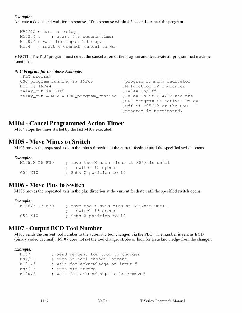
11-6 3/4/04 T-Series Operator’s Manual
Example: Activate a device and wait for a response. If no response within 4.5 seconds, cancel the program.
M94/12 ; turn on relay M103/4.5 ; start 4.5 second timer M100/4 ; wait for input 4 to open M104 ; input 4 opened, cancel timer
● NOTE: The PLC program must detect the cancellation of the program and deactivate all programmed machine functions. PLC Program for the above Example:
;PLC program CNC_program_running is INP65 ;program running indicator M12 is INP44 ;M-function 12 indicator relay_out is OUT5 ;relay On/Off relay_out = M12 & CNC_program_running ;Relay On if M94/12 and the ;CNC program is active. Relay ;Off if M95/12 or the CNC ;program is terminated.
M104 - Cancel Programmed Action Timer M104 stops the timer started by the last M103 executed.
M105 - Move Minus to Switch M105 moves the requested axis in the minus direction at the current feedrate until the specified switch opens. Example:
M105/X P5 F30 ; move the X axis minus at 30"/min until ; switch #5 opens G50 X10 ; Sets X position to 10
M106 - Move Plus to Switch M106 moves the requested axis in the plus direction at the current feedrate until the specified switch opens. Example:
M106/X P3 F30 ; move the X axis plus at 30"/min until ; switch #3 opens G50 X10 ; Sets X position to 10
M107 - Output BCD Tool Number M107 sends the current tool number to the automatic tool changer, via the PLC. The number is sent as BCD (binary coded decimal). M107 does not set the tool changer strobe or look for an acknowledge from the changer. Example:
M107 ; send request for tool to changer M94/16 ; turn on tool changer strobe M101/5 ; wait for acknowledge on input 5 M95/16 ; turn off strobe M100/5 ; wait for acknowledge to be removed

T-Series Operator’s Manual 3/4/04 11-7
M108 - Enable Override Controls M108 re-enables the feedrate override and/or spindle speed override controls if they have previously been disabled with M109. A parameter of 1 indicates the feedrate override; a parameter of 2 indicates the spindle speed override. Example:
M109/1/2 ; disable feedrate and spindle speed overrides M108/1 ; re-enable feedrate override M108/2 ; re-enable spindle speed override
M109 - Disable Override Controls M109 disables the feedrate override and/or spindle speed override controls. M109 cannot be used in MDI mode. Example:
M3 S500 ; start spindle clockwise, 500 rpm M109/1/2 ; disable feedrate and spindle speed overrides M108/1/2 ; re-enable overrides
M115/M116/M125/M126 – Protected Move Probing Functions The protected move probing functions provide the capability to program customized probing routines. The structure for these commands is: Mnnn /Axis p os Pp Ff nnn is either 115, 116, 125, or 126. Axis is a valid axis label, i.e., X, Y, Z, etc. pos is an optional position p is a plc bit number, which can be negative. f is a feedrate (in units per minute.)
For M115 and M116 functions, the indicated axis will move to pos (if specified) until the corresponding plc bit p state is 1, unless p is negative, in which case movement is until the plc bit state is 0. A p value of 1 to 80 (or -1 to -80) specifies plc bits INP1-INP80, 81 to 160 (or -80 to -160) specifies plc bits OUT1-OUT80, and 161 to 240 (or -161 to -240) specifies plc bits MEM1-MEM80. Warnings are generated in the CNC7 message window for "Missing P value" and "Invalid P value." If pos is not specified, M115 will move axis in the negaive direction, and M116 will move axis in the positive direction. Note that is pos is specified, then if does not matter whether M115 or M116 is used. If pos is not specified, the movement is bounded by the settings in the software travel limits. In the abscence of software travel limits, movement is bounded by the maximum probing distance (Machine Parameter 16). In cases where pos is specified, it is still bounded by the software travel limits. If the bounded position is reached before the awaited plc bit state is found, a "Probe unable to detect surface" error will be generated, which will stop any running job. For M125 and M126 protected move functions, the behavior is identical to that of the M115 and M116 commands, except in regards to the plc bit state. M125 and M126 will generate an "Unexpected probe contact" error message if the specified plc bit state is triggered, again stopping any running job.
In summary, the M115 and M116 commands are to be used when one expects contact to be made, and M125 and M126 commands are to be used when one does not expect any contact to be made. Example:
M115/X P-15 F20 ; Move X minus at 20ipm waiting for contact on INP15

11-8 3/4/04 T-Series Operator’s Manual
M116/X P15 F5 ; Move X plus until no contact at 5 ipm
M120 - Open data file (overwrite existing file) This M function will open the requested data file for writing. If no drive or directory is specified with the file name, then the file will be opened in the same directory as the CNC program. If the file cannot be successfully opened, then an error will be returned, ultimately terminating the job. If a data file is already open when M120 is called, that file will first be closed, then the new file opened. Example:
M120 "probetst.dat"
M121 - Open data file (append to existing file) This M function will open the requested file for writing at the end of the file. If no drive or directory is specified with the file name, then the file will be opened in the same directory as the CNC program. If the file does not already exist, it will be created. This is not an error. If the file cannot be successfully opened, then an error will be returned, ultimately terminating the job. If a data file is already open when M121 is called, that file will first be closed, then the new file opened. Example:
M121 "c:\probetst.dat"
M122 - Record position(s) and optional comment in data file This M function will write the current expected position value to the data file, in the usual format (i.e. axis label before number, 4 decimal places in inch mode, 3 decimal places in millimeter mode. Any comment that appeared on the line with M122 will be output after the position(s). With no axis arguments, M122 will write the positions of all installed axes. With axis arguments, it will write the positions only of the requested axes. Positions will be written in local (not machine) coordinates, in native machine units. If no data file has been opened with M120 or M121 before M122 is called, then M122 will return an error and terminate the job. The parameter L1 may be used to suppress the new line character normally outputted after the last position. Examples (M function and sample output):
M122 -> X1.2345 Y-3.2109 Z-0.5678 M122 /Z ; at 10 ipm -> Z-.4321 ; at 10 ipm M122 /X/Z -> X-1.0000 Z0.8732 M122 /X L1 -> X-1.5000 M122 /X -> X-1.5000 X-2.0000
M123 - Record value and/or comment in data file This M function will write the specified parameter value (if any) to the data file, followed by any comment that appeared on the line with M123. If a P value is specified, M123 will output a ';' character followed by the numeric value (4 decimal places in inches, 3 in millimeters). If no P value is specified, then M123 outputs the comment only. If neither a P value nor a comment was specified, M123 does nothing. This is not an error. If no data file has been opened with M120 or M121 before M123 is called, then M123 will return an error and terminate the job. The parameter L1 may be used to suppress the new line character normally outputted after the last value. Examples (M function and sample output):
M123 P1.2345 -> ; 1.2345 M123 P#A ; first macro argument -> ; 1.2345 ; first macro argument M123 ; Probing X+ to surface -> ; probing X+ to surface M123 -> <nothing>
M151 – Unwind C axis This M function will reset the C axis position to less than one revolution of the C axis (< 360 degrees).

T-Series Operator’s Manual 3/4/04 11-9
Example (M51) G97 ; Turn off CSS (constant surface speed) M3 S0 ; Turn off spindle M101/9 ; Wait for zero speed signal form inverter on INP9 M94/9 ; Switch to torque mode M51 ; Perform the default actions for C axis enable M151 ; Unwind C-axis position
Note in the above examples for M50 and M51 where the M95/9 (turn off INP41) and M94/9 (turn on INP41) commands are used, it is assumed that the plc program, conditioned upon the state of INP41, has been modified to output the appropriate hardware signals required to switch between speed and torque mode.
Warning: The spindle must be stopped before issuing the M151 or unpredictable positions can result.


T-Series Operator’s Manual 3/4/04 12-1
CHAPTER 12 CNC Program Example
CNC Program N010 G20 N015 G50 S3000 N020 G00 T0303 N025 G97 S1777 M03 N030 G00 X1.72 Z0. N035 G96 S800 N040 X1.72 N045 G99 G01 Z-1.955 F.01 N050 X1.7901 N055 X2.02 Z-2.0699 N060 Z-2.215 N065 X2.04 N070 G00 Z0. N075 X1.42 N080 G01 Z-1.955 N085 X1.74 N090 G00 Z0. N095 X1.12 N100 G01 Z-1.955 N105 X1.44 N110 G00 Z0. N115 X.82 N120 G01 Z-1.955 N125 X1.14 N130 G00 Z0. N135 X.52
N140 G01 Z-1.955 N145 X.84 N150 G00 Z0. N155 X.52 N160 G01 Z-1.955 N165 X.54 N170 G00 X2.1 N175 G97 S3000 N180 Z0. N185 X.5 N190 G96 S1000 N195 G01 Z-1.965 F.003 N200 X1.7818 N205 X2. Z-2.0741 N210 Z-2.215 N215 G28 T0300 N220 M05 N225 M00 N230 G50 S3000 N235 G00 T0404 N240 G97 S1135 M03 N245 G00 X2.02 Z-2.228 N250 G96 S600 N255 X2.02 N260 G99 G01 X1.1932 N265 G00 X2.02

12-2 3/4/04 T-Series Operator’s Manual
N270 Z-2.2392 N275 G01 X1.2005 N280 G00 X2.02 N285 Z-2.2503 N290 G01 X1.2078 N295 G00 X2.02 N300 Z-2.2615 N305 G01 X1.2151 N310 G00 X2.02 N315 Z-2.2727 N320 G01 X1.2224 N325 G00 X2.02 N330 Z-2.2838 N335 G01 X1.2297 N340 G00 X2.02 N345 Z-2.295 N350 G01 X1.237 N355 G00 X2.02 N360 Z-2.3062 N365 G01 X1.2444 N370 G00 X2.02 N375 Z-2.3173 N380 G01 X1.2517 N385 G00 X2.02 N390 Z-2.3285 N395 G01 X1.259 N400 G00 X2.02 N405 Z-2.3396 N410 G01 X1.2663 N415 G00 X2.02 N420 Z-2.3508 N425 G01 X1.2736 N430 G00 X2.02 N435 Z-2.362 N440 G01 X1.2809 N445 G00 X2.02 N450 Z-2.3731 N455 G01 X1.2882 N460 G00 X2.02 N465 Z-2.3843 N470 G01 X1.2956
N475 G00 X2.02 N480 Z-2.3955 N485 G01 X1.3029 N490 G00 X2.02 N495 Z-2.4066 N500 G01 X1.3102 N505 G00 X2.02 N510 Z-2.4178 N515 G01 X1.3175 N520 G00 X2.02 N525 Z-2.429 N530 G01 X1.3248 N535 G00 X2.02 N540 Z-2.4401 N545 G01 X1.3321 N550 G00 X2.02 N555 Z-2.4513 N560 G01 X1.3394 N565 G00 X2.02 N570 Z-2.4625 N575 G01 X1.3468 N580 G00 X2.02 N585 Z-2.4736 N590 G01 X1.3541 N595 G00 X2.02 N600 Z-2.4848 N605 G01 X1.3614 N610 G00 X2.02 N615 Z-2.496 N620 G01 X1.3687 N625 G00 X2.02 N630 G97 S1910 N635 Z-2.218 N640 X2. N645 G96 S1000 N650 G01 X1.1656 N655 X1.3497 Z-2.4991 N660 G28 T0400 N665 M05 N670 M30

T-Series Operator’s Manual 3/4/04 13-1
CHAPTER 13 The Operator Panel
NOTE: The arrangement of controls on your Operator Panel may vary from the above illustration, depending on the model of your control The operator panel is a sealed membrane keyboard that enables you to control various machine operations and functions. The panel contains momentary membrane switches, which are used in combination with LED indicators to tell you the status of the machine functions. The keys are grouped according to function (jogging, spindle, coolant) and may or may not have LED indicators.

13-2 3/4/04 T-Series Operator’s Manual
Axis Jog Buttons X+ X- Z+ Z-
The X and Z keys are momentary switches for jogging each of the 2 axes of the machine. There are two buttons for each axis (+/-). Only one axis can be jogged at a time.
Jog Speed Selection FAST/SLOW
FAST/SLOW selects between fast and slow jogging. When FAST jog is selected (LED off) and a jog button is pressed, the axis will move at the fast jog rate. If slow jog is selected (LED on) the axis will move at the slow jog rate. See Chapter 14 for information on setting the fast and slow jog rates for each axis.
Jog Mode Selection CONT/INCR
CONT/INCR selects between continuous and incremental jogging. Pressing the key will toggle between those two modes. When the INCR jog is selected, as indicated by the LED, and a jog button is pressed, the axis will move the current jog increment distance and stop. The jog button must be released and then pressed again before any further axis movement can occur. If CONT jog is selected and an axis jog button is pressed, the axis will move continuously until the button is released. ● NOTE: The jog buttons will not operate if the T-Series CNC software is not running, the E-Stop button is engaged, or a job (a CNC program) is running.
Jog Increment Keys x1, x10, x100
To set the jog increment, press any one of these keys. The amount you select here is the distance the control will move an axis if you make an incremental jog (x1=0.0001", x10=0.0010" and x100=0.0100"). You may select only one jog increment at a time, and the key that has a lit LED indicates the current jog increment. The jog increment you select is for all axes; you cannot set separate jog increments for each axis. The jog increment also selects the distance the control will move an axis for each click of the MPG handwheel.
MPG Press this key to convert the control over to Manual Pulse Generator mode. When turned on, the LED will be lit. In continuous mode, the MPG will control the fast jog of the machine. In incremental mode, each click of the handwheel will jog the machine incrementally (X1 or X10) at a distance indicated by the Jog increment key that has its LED turned on.
TOOL CHECK Pressing TOOL CHECK while a job (a CNC program) is not running will move the table to its tool change (G28) position. Pressing TOOL CHECK while a job is running will stop normal program movement, clear all M-functions, and automatically display the Resume Job Menu. From the Resume job menu, you will be able to change tool settings. ● NOTE: When a job is running, pressing TOOL CHECK once stops the job and allows you to manually jog the tool clear. Pressing TOOL CHECK a second time will cause the tool to move to its tool change (G28) position.
SINGLE BLOCK The SINGLE BLOCK key selects between Auto mode and Single Block mode. Single Block mode allows you to run a program line by line by pressing CYCLE START after each block. While in Single Block mode you can select Auto Block mode at any time, but while in Auto Block mode and a program is running you cannot select Single Block mode. Auto Block mode runs the loaded program after CYCLE START is pressed. Auto Block mode is the default. When Single Block mode is selected, the LED will be lit.
CYCLE START When the CYCLE START button is pressed, the T-Series Control will immediately begin processing the current program at the beginning and will prompt you to press the CYCLE START button again to begin execution of the program. After an M0, M1, M2, or tool change is encountered in the program, the message

T-Series Operator’s Manual 3/4/04 13-3
Press CYCLE START to continue
will be displayed on the screen, and the T-Series Control will wait until you press the CYCLE START button before continuing program execution. ● NOTE: Pressing CYCLE START will cause the T-Series Control to start moving the axes immediately without further warning. Be certain that you are really ready to start the program when you press this button. Pressing the FEED HOLD button, E-STOP, or the CYCLE CANCEL button will stop any movement if CYCLE START is pressed accidentally.
CYCLE CANCEL Pressing CYCLE CANCEL while a program is running will cause the T-Series Control to abort the current program. The control will stop moving immediately, clear all M-functions and return to the Main Screen. It is recommended that you press FEED HOLD first before CYCLE CANCEL. If you press CYCLE CANCEL, program execution will stop; if you wish to restart the program you must rerun the entire program or use the search function. See the Search function operation in Chapter 2.
COOLANT ON/OFF The COOLANT ON/OFF key is only operational when manual coolant mode has been selected. If the COOLANT ON/OFF LED is lit, coolant is on. Pressing this button turns the coolant on and off in the manual mode.
COOLANT AUTO/MAN Pressing this key will select auto coolant mode. The COOLANT AUTO/MAN LED will be lit if auto coolant mode is selected. If the COOLANT AUTO/MAN LED is not lit, the T-Series Control is in manual coolant mode. COOL AUTO is the default.
COOLANT FLOOD/MIST The COOLANT FLOOD/MIST key is used to select between flood coolant and mist coolant. You can select between flood and mist coolant at any time, either in Auto or Manual coolant mode. The COOLANT FLOOD/MIST LED will be lit if flood coolant is selected. If the COOLANT FLOOD/MIST LED is not lit, then Mist Coolant mode will be selected.
SPINDLE CW/CCW The SPINDLE CW/CCW key determines the direction the spindle will turn if it is started manually. If the spindle is started automatically, the direction key is ignored and the spindle runs according to what was programmed. When the LED is lit, the spindle will spin clockwise, and when the LED is not lit, the spindle will spin counterclockwise. The current direction of the spindle will be indicated by the LED when the spindle is running in automatic mode. Pressing the SPINDLE CW/CCW key toggles it from clockwise to counterclockwise and vice versa. The default is CW.
SPINDLE AUTO/MAN This key selects whether the spindle will operate under program control (automatic) or under operator control (manual). When the LED is lit, the spindle is under program control. If the LED is not lit, the spindle is under operator control. Pressing the SPINDLE AUTO/MAN key will toggle it from manual to auto and back again. The default is Auto mode.
SPIN START Pressing the SPIN START key when manual spindle mode is selected will cause the spindle to start rotating. Pressing SPIN START when automatic mode is selected restarts the spindle if it has been paused with SPIN STOP.
SPIN STOP Pressing the SPIN STOP key when manual spindle mode is selected will stop the spindle. Pressing SPIN STOP when automatic mode is selected pauses spindle rotation and can be restarted with SPIN START. WARNING: SPIN STOP should only be pressed during FEED HOLD or when a program is NOT running.

13-4 3/4/04 T-Series Operator’s Manual
FEEDRATE OVERRIDE This knob is the percentage of the programmed feedrate that you want to use during feedrate cutting moves. This percentage can be from 2% to 200%.
SPINDLE OVERRIDE This knob is the percentage of the Spindle Speed that will be used by variable frequency spindle drive. In AUTO Mode, the SPINDLE OVERRIDE knob is a percentage override (2% - 200%) of the programmed Spindle Speed (see Chapter 14 for how to assign a spindle speed). In Manual Mode, the knob controls Spindle Speed directly, from 0 to the maximum spindle speed.
T-STOCK IN, T-STOCK OUT, QUILL IN, QUILL OUT, TURRET INDEX
These buttons currently have no settings. However, any of these keys can be programmed to control hydraulic stock clamps, Quills, or Turret index through the PLC. Your installer will provide you with the necessary documentation explaining the operation and functions these keys perform.
RAPID OVER When the LED is lit on the RAPID OVER key, the control is in Rapid Override mode. In this mode, all rapids in all operating modes can be regulated using the FEEDRATE OVERRIDE knob. The default speed is specified in the Machine parameter. More information on machine parameters can be found in Chapter 14 (Configuration).
FEED HOLD Feed Hold decelerates motion of the current movement to a stop, pausing the job that is currently running. Releasing FEED HOLD will continue the movement from the stopped location.
EMERGENCY STOP EMERGENCY STOP releases the power to all the axes and cancels the current job immediately upon being pressed. EMERGENCY STOP also resets certain faults if the fault condition has been fixed or cleared.
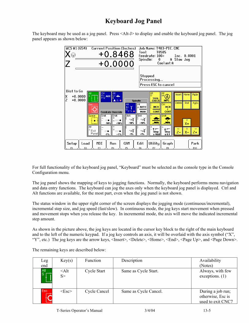
T-Series Operator’s Manual 3/4/04 13-5
Keyboard Jog Panel The keyboard may be used as a jog panel. Press <Alt-J> to display and enable the keyboard jog panel. The jog panel appears as shown below:
For full functionality of the keyboard jog panel, “Keyboard” must be selected as the console type in the Console Configuration menu. The jog panel shows the mapping of keys to jogging functions. Normally, the keyboard performs menu navigation and data entry functions. The keyboard can jog the axes only when the keyboard jog panel is displayed. Ctrl and Alt functions are available, for the most part, even when the jog panel is not shown. The status window in the upper right corner of the screen displays the jogging mode (continuous/incremental), incremental step size, and jog speed (fast/slow). In continuous mode, the jog keys start movement when pressed and movement stops when you release the key. In incremental mode, the axis will move the indicated incremental step amount. As shown in the picture above, the jog keys are located in the cursor key block to the right of the main keyboard and to the left of the numeric keypad. If a jog key controls an axis, it will be overlaid with the axis symbol (“X”, “Y”, etc.) The jog keys are the arrow keys, <Insert>, <Delete>, <Home>, <End>, <Page Up>, and <Page Down>. The remaining keys are described below:
Legend
Key(s) Function Description Availability (Notes)
<Alt S>
Cycle Start Same as Cycle Start. Always, with few exceptions. (1)
<Esc> Cycle Cancel Same as Cycle Cancel. During a job run; otherwise, Esc is used to exit CNC7

15-6 4/17/01 T-Series Operator’s Manual
Legend
Key(s) Function Description Availability (Notes)
used to exit CNC7 menus.
<Space> or <Alt H>
Feed Hold Turns Feed Hold on and off The space key may be used for editing and may not be available at all times. Alt-H is always available.
<Alt J> Start/Exit Panel
Invokes or exits the jog panel. Always, with few exceptions. (1)
<Ctrl F1> - <Ctrl F12>
Aux 1 – Aux 12
Executes the corresponding Aux function and signals the PLC. A custom PLC program is required to act upon jog panel signals.
Always, with few exceptions. (1,3)
<Alt C> and <Alt Q>
Flood Coolant and Mist Coolant
Alt C turns flood coolant on and off. Alt E turns mist coolant on and off. Both flood and mist may be on at the same time. Either key automatically selects manual coolant mode. If requested by CNC7, Alt C and Alt E will select “Auto Coolant Mode”. Press either when prompted.
Always, with few exceptions. (1,3)
<Shift -> or <_>
Feed Rate Override –10%
Decreases the feed rate override by 10%.
Jog panel, job run, graphing, and some other times. (2,4)
<Shift => or <+>
Feed Rate Override +10%
Increases the feed rate override by 10%.
Jog panel, job run, graphing, and some other times. (2,4)
<-> Feed Rate Override –1%
Decreases the feed rate override by 1%.
Jog panel, job run, graphing, and some other times. (2,4)
<=> Feed Rate Override +1%
Increases the feed rate override by 1%.
Jog panel, job run, graphing, and some other times. (2,4)
<Alt R> and <Alt Q>
Spindle On/Off CW/CCW
Alt R turns the spindle on clockwise if the spindle is off; otherwise, it turns the spindle off. Alt Q is similar except counter-clockwise. Either will automatically select manual spindle operation.
Always, with few exceptions. (1,3)
<Alt A>
Spindle Auto/ Manual
Toggles between automatic and manual spindle operation.
Always, with few exceptions. (1,3)
<Shift [> or <{>
Spindle Override –10%
Decreases the spindle override by 10%.
Only in jog panel, and during a job. (2,4)

T-Series Operator’s Manual 3/4/04 13-7
Legend
Key(s) Function Description Availability (Notes)
<Shift ]> or <}>
Spindle Override +10%
Increases the spindle override by 10%.
Only in jog panel, and during a job. (2, 4)
<[> Spindle Override –1%
Decreases the spindle override by 1%.
Only in jog panel, and during a job. (2,4)
<]> Spindle Override +10%
Increases the spindle override by 1%. Only in jog panel, and during a job. (2,4)
<Alt O>
Tool Check Performs a tool check. Always, with few exceptions. (1)
<Alt W>
MPG on/off Turns MPG (handwheel) control on and off.
Available most times that jogging is available.
<|> or <\>
Incremental/ Continuous Jog Selection
Selects incremental or continuous jog mode. Press again to select the opposite mode.
Only in jog panel.
Ctrl (as modifier)
Incremental/ Continuous Jog
Fast and temporary incremental/continuous mode switch. Hold down simultaneously with a jog key. (This is like holding down the Shift key to type a capital letter instead of pressing Caps Lock.)
Only in jog panel.
<‘> or <~>
Fast/ Slow Jog Selection
Selects fast or slow jog mode. Press again to select the opposite mode.
Only in jog panel.
Shift (as modifier)
Fast/Slow Jog Selection
Fast and temporary fast/slow mode switch. Hold down simultaneously with a jog key. (This is like holding down the Shift key to type a capital letter instead of pressing Caps Lock.)
Only in jog panel.
<,> or <<>
Increase Jog Step 10x
Changes incremental jog step from .0001 to .001 to .01, etc. (The “1” moves to the left in the status window.) This also selects handwheel speed.
Only in jog panel.
<.> or <>>
Decrease Jog Step 10x
Changes incremental jog step from .1 to .01 to .001, etc. (The “1” moves to the right in the status window.) This also selects handwheel speed.
Only in jog panel.
<F1> – <F10>
F key pass-thru
Exits the jog panel and executes the corresponding F key.
Where F keys are visible.
Notes: Hot key. In general, the key can be used at any time. Some CNC7 menus may prevent the use of certain keys.

15-8 4/17/01 T-Series Operator’s Manual
The console type in the console configuration menu must be set to “Keyboard” to use this key. The PLC program must be programmed to support this key. Keyboard only systems have this support built-in. Systems with other jog panels may not have this support. Available if not in use by CNC7. For example, feed rate override can be adjusted from the main menu. If you are editing a value in a table or menu, you cannot adjust feed rate override.
MDI and the Keyboard Jog Panel Many of the keys used by the keyboard jog panel are also possible commands to MDI. To use the keyboard jog panel functions in MDI, you must press <Alt J>. You may jog, use the handwheels or any other jog panel function. Press <Alt J> or <Esc> to return to MDI.

T-Series Operator’s Manual 3/4/04 14-1
CHAPTER 14 Configuration
(F3 from Setup)
General The configuration option provides you with a means for modifying the machine and control configuration. The majority of information in this section should not be changed without contacting your dealer. WARNING: Some of the data, if corrupt or incorrect, could cause personal injury or machine damage.
Password When you press F3 from the Setup Menu, you may be prompted to enter a password. This level of security is necessary so that users do not accidentally change vital parameters. The original default password is distributed in the documentation provided to the owner of the machine when the control is installed. This password is changeable via parameter 42. If you know the password, type it and press <ENTER>. If the password you enter is incorrect, a message will appear telling you the password was incorrect and the password prompt will reappear. Pressing <ESC> will remove the prompt. If you don't know the password, simply press <ENTER>. You will be given access to the configuration options so that you can view the information. However, you will not be able to change any of the data.

14-2 3/4/04 T-Series Operator’s Manual
Control Configuration Pressing F1 from the configuration menu will display the Control Configuration menu in the edit window. The Control Configuration menu provides you with a method of changing control dependent data. Each of the fields is discussed in detail below. If you wish to change a field, use the up and down arrow keys to move the cursor to the desired field. Type the new value and press <ENTER>, or press <SPACE> to toggle. When you are done editing, press F10 to save any changes you have made. If you wish to discard your changes and restore the previous values, press <ESC>.
DRO Display Units
This field controls the units of measure the DRO displays. The two options are ' Millimeters ' and ' Inches '. When this field is highlighted by the cursor, "Press SPACE to change" appears at the bottom of the menu. This message is explaining that pressing the <SPACE> key will toggle the value of this field between the two options. The DRO display units do not have to be the same as the machine units of measure (explained below). This field is provided for users of the G20 & G21 codes so that they may view the tool position in terms of job units (see Chapter 10).
Machine Units of Measure This field controls which units of measure the machine uses for each job. The two options are ' Millimeters ' and 'Inches'. Press <SPACE> to toggle the field between the two options. This field determines the default interpretation of job dimensions and feedrates. If ' Inches ' is selected, all feedrates and dimensions will be interpreted as inches as well as any unit dependent parameters. ● NOTE: This field should rarely, if ever, be changed. If you wish to run a job in units other than the default machine units, use the G20 & G21 codes.

T-Series Operator’s Manual 3/4/04 14-3
Maximum Spindle Speed (High Range) This field sets the high range maximum spindle speed. All spindle speeds entered in a CNC program are output as percentages of this maximum value. If your machine is equipped with a multi-range drive, the control will not exceed the spindle speed set by this field while in high gear. See the Machine Parameters section for information on setting the gear ratios for medium and low gear ranges. If your machine is not equipped with a multi-range drive, this field determines the maximum spindle speed.
Minimum Spindle Speed (High Range) This parameter is used to adjust the minimum spindle speed for the high range. This parameter allows the operator to set the minimum value for spindle speed to a value other than 0. All changes in spindle speed are made in relationship to this value, with this parameter as the minimum value. The values stored can range from 0 to 500000.0 RPM.
Machine Home At Powerup This field controls how the machine will home at powerup. Set Machine Home at Powerup to Limit Switch if you have limit/home switches or safe hard stops for all axes, and wish to use the switches or stops for homing. Set Machine Home at Powerup to Ref Mark if you have fixed reference marks for any axis. In Ref Mark homing, axes that contain a zero (0) for the plus or minus home switch in the Machine Configuration designate that axis to have a Ref Mark home, while non-zero values specify Limit Switch homing. Set Machine Home at Powerup to Jog if you need to manually move or jog the machine to its home position. See Chapter 1 for more information about machine home.
PLC Type This field tells the control which PLC type is installed. The possible values are Absent, Lite, Normal, and Dual. The value should not be changed unless a different PLC type is installed. Use the <SPACE> key to select among the four options. The standard PLC types installed are dependent on your T-series number and the options that may have been purchased. Check the information sheet on page ix for which type of PLC is installed on your machine, or check with your dealer for more information.
Console Type Set for type of console installed. "T-" for lathe, "M-" for mill.
Jog Panel Required This field tells the control whether <CYCLE START> must be pressed once or twice before a job is started. Set to “No” will require only one <CYCLE START> press to begin a job.
Screen Blank Delay This field determines the delay used for the screen blank function. When a value other than zero is set, the screen will blank after the specified number of minutes. The blanking function only works if no jobs are running. The value you enter is measured in minutes. Therefore, a value of 5 would blank the screen in 5 minutes if no actions were taken. When the screen is blank, pressing any key will restore the screen. If you do not wish to use this feature, enter a value of zero to disable it. However, if the display is kept on for long periods of time without the blanker enabled, the image of a screen may become ' burned ' into the monitor. That is, you will be able to see this image of the screen on the monitor whether the monitor is on, off, or displaying a different screen image.
Remote Drive & Directory This field sets up the remapped default drive and directory for the F3 key in the Load Job screen. This allows you to conveniently load files from an attached computer via an RS232 null modem cable or LAN network (via RJ-45 Ethernet connection). The Control will usually remap the attached computer's C hard drive as drive E, depending on the way it was set up. You must run the INTERSVR program (supplied with IBM DOS) on the attached computer in order for this feature to work using the RS-232 connection.

14-4 3/4/04 T-Series Operator’s Manual
User Specified Paths Operators can now specify paths for INTERCON files and posted INTERCON files. These paths are specified in PATHL.INI. This file is automatically generated by CNC7 if it does not exist. The default PATHL.INI file is:
INTERCON_PATH=C:\ICN_LATH\ ICN_POST_PATH=C:\CNC7T\NCFILES\
Path tag Purpose of path INTERCON_PATH Main directory containing *.LTH files ICN_POST_PATH Directory INTERCON places *.CNC files created when posting *.LTH files.

T-Series Operator’s Manual 3/4/04 14-5
Machine Configuration Pressing F2 from the configuration menu will bring up the machine configuration menu, which provides you with a method of changing machine dependent data. If you wish to change a field, press F1 or F2 to select the Jog or Motor fields, use the arrow keys to move the cursor and select the desired field. Type the new value and press <ENTER> or press <SPACE> to toggle. When you are done editing, press F10 to save any changes you have made. If you wish to discard your changes and restore the previous values, press <ESC>. Pressing <ESC> again will return you to the previous menu (Setup). ● NOTE: Although X appears on the first line of the DRO and Z appears on the second, their order is reversed on all configuration menus. ● NOTE: Some of these values are set automatically by the Autotune option (See PID Configuration later in this chapter). WARNING: The Motor Parameters should not be changed without contacting your dealer. Corrupt or incorrect values could cause damage to the machine, personal injury, or both.
F1 - Jog Parameters (Values should be recorded on the Information Sheet at the beginning of this manual.)
This screen contains jog and feedrate information. See the figure below.
A description of each of these parameters is listed below. ● NOTE: Some of these values are set automatically by the Autotune option (See PID Configuration later in this chapter). Slow Jog: Determines the speed of motion on an axis when slow jog is selected and a jog button is pressed. The slow jog rate cannot be set to a value greater than the maximum rate.

14-6 3/4/04 T-Series Operator’s Manual
Fast Jog: Determines the speed of motion on an axis when fast jog is selected and a jog button is pressed. The fast jog rate cannot be set to a value greater than the maximum rate. Max Rate: Determines the maximum feedrate of each individual axis. The feedrate on each axis can never exceed Max Rate, even if the feedrate override knob on the front panel is turned up above 100%. (See also the Machine Parameters section for the "Multi-Axis Max Feedrate" parameter that limits the feedrate along move vectors, not just each individual axis.) ● NOTE: The maximum rate may be set to a smaller value if you wish to run your machine at a slower rate. Deadstart: Determines the speed to which an axis decelerates before stopping or reversing direction. A low setting will cause a large slowdown before reversals of direction, causing your machine to be more accurate. A high setting will cause less slowdown before reversals, but this may cause your machine to "bang" and you may lose accuracy. This parameter should not be changed. Delta Vmax: The maximum instantaneous velocity change that will be commanded on a vector transition. This parameter should not be changed. Travel (-): The maximum distance the axis can travel in the minus direction from the home position. Set this parameter to create a software limit that stops the axis before the fixture or tool collides with the machine. Travel (+): The maximum distance the axis can travel in the plus direction from the home position. This parameter is especially useful when using a part or fixture larger than the lathe bed. Set this parameter to create a software limit that stops the axis before the fixture or tool collides with the machine.
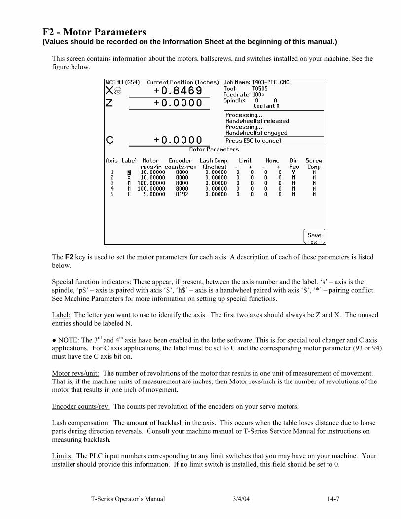
T-Series Operator’s Manual 3/4/04 14-7
F2 - Motor Parameters (Values should be recorded on the Information Sheet at the beginning of this manual.)
This screen contains information about the motors, ballscrews, and switches installed on your machine. See the figure below.
The F2 key is used to set the motor parameters for each axis. A description of each of these parameters is listed below. Special function indicators: These appear, if present, between the axis number and the label. ‘s’ – axis is the spindle, ‘p$’ – axis is paired with axis ‘$’, ‘h$’ – axis is a handwheel paired with axis ‘$’, ‘*’ – pairing conflict. See Machine Parameters for more information on setting up special functions. Label: The letter you want to use to identify the axis. The first two axes should always be Z and X. The unused entries should be labeled N. ● NOTE: The 3rd and 4th axis have been enabled in the lathe software. This is for special tool changer and C axis applications. For C axis applications, the label must be set to C and the corresponding motor parameter (93 or 94) must have the C axis bit on. Motor revs/unit: The number of revolutions of the motor that results in one unit of measurement of movement. That is, if the machine units of measurement are inches, then Motor revs/inch is the number of revolutions of the motor that results in one inch of movement. Encoder counts/rev: The counts per revolution of the encoders on your servo motors. Lash compensation: The amount of backlash in the axis. This occurs when the table loses distance due to loose parts during direction reversals. Consult your machine manual or T-Series Service Manual for instructions on measuring backlash. Limits: The PLC input numbers corresponding to any limit switches that you may have on your machine. Your installer should provide this information. If no limit switch is installed, this field should be set to 0.

14-8 3/4/04 T-Series Operator’s Manual
Homes: The PLC input numbers of any Home Switches you may have. These are similar to the limit switches. If your machine does not have home switches, this field should be set to the Limit Switch value. If no home or limit switch is installed, this field should be set to 0. You may then use hard stops as homing points if you choose. ● NOTE: The Home Switch should never be physically located beyond the Limit Switch. Direction reversed: Used to match the +/- reference of your machine to the control electronics. Toggle this value if you actually move in the Z direction (reverse) when you jog Z+. Screw Compensation: This value indicates whether mapping ballscrew compensation is enabled. When enabled a preset ballscrew map compensates for error along the entire ballscrew. For more information, contact your dealer. It is recommended you enable ballscrew error compensation at all times.
F3 - Find Home Press F3 to move an axis to its plus or minus home switch.
F4 - Set Home Press F4 to set Machine Home for an axis at its current position. This is usually performed after Find Home. This operation should not be used to set the part zero position. To set the part zero position, use the Part Setup menu as described in Chapter 4.
F5 – Manual Ballscrew Compensation This option lets you edit the ballscrew compensation tables. * WARNING: The ballscrew compensation tables should not be changed without contacting your dealer. Corrupt or incorrect values could adversely affect the accuracy of the positioning of your machine.

T-Series Operator’s Manual 3/4/04 14-9
Machine Parameters
This screen provides you with a method of changing various parameters that are used by the control. If you wish to change a field, use the arrow keys to move the cursor and select the desired field. Type the new value and press <ENTER>. When you are done editing the fields, press F10 to accept any changes you have made and save them. Press <ESC> to return to the previous menu [Setup]. <F3> Next Table will toggle the display parameters between parameters 0-99 and parameters 100-199. ● NOTE: Many machine parameters can also be set with the G10 G-code.
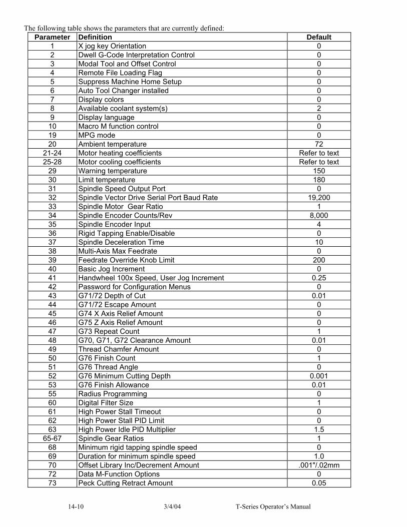
14-10 3/4/04 T-Series Operator’s Manual
The following table shows the parameters that are currently defined: Parameter Definition Default
1 X jog key Orientation 0 2 Dwell G-Code Interpretation Control 0 3 Modal Tool and Offset Control 0 4 Remote File Loading Flag 0 5 Suppress Machine Home Setup 0 6 Auto Tool Changer installed 0 7 Display colors 0 8 Available coolant system(s) 2 9 Display language 0
10 Macro M function control 0 19 MPG mode 0 20 Ambient temperature 72
21-24 Motor heating coefficients Refer to text 25-28 Motor cooling coefficients Refer to text
29 Warning temperature 150 30 Limit temperature 180 31 Spindle Speed Output Port 0 32 Spindle Vector Drive Serial Port Baud Rate 19,200 33 Spindle Motor Gear Ratio 1 34 Spindle Encoder Counts/Rev 8,000 35 Spindle Encoder Input 4 36 Rigid Tapping Enable/Disable 0 37 Spindle Deceleration Time 10 38 Multi-Axis Max Feedrate 0 39 Feedrate Override Knob Limit 200 40 Basic Jog Increment 0 41 Handwheel 100x Speed, User Jog Increment 0.25 42 Password for Configuration Menus 0 43 G71/72 Depth of Cut 0.01 44 G71/72 Escape Amount 0 45 G74 X Axis Relief Amount 0 46 G75 Z Axis Relief Amount 0 47 G73 Repeat Count 1 48 G70, G71, G72 Clearance Amount 0.01 49 Thread Chamfer Amount 0 50 G76 Finish Count 1 51 G76 Thread Angle 0 52 G76 Minimum Cutting Depth 0.001 53 G76 Finish Allowance 0.01 55 Radius Programming 0 60 Digital Filter Size 1 61 High Power Stall Timeout 0 62 High Power Stall PID Limit 0 63 High Power Idle PID Multiplier 1.5
65-67 Spindle Gear Ratios 1 68 Minimum rigid tapping spindle speed 0 69 Duration for minimum spindle speed 1.0 70 Offset Library Inc/Decrement Amount .001"/.02mm 72 Data M-Function Options 0 73 Peck Cutting Retract Amount 0.05

T-Series Operator’s Manual 3/4/04 14-11
78 Display of spindle speed 0 79 Auto brake mode PLC bit for Uniconsole-2 70 80 Voltage Brake Applied Message Frequency 1 82 Spindle drift adjustment 0.0 83 Deep Hole Clearance Amount 0.05 84 Spindle CW M-Function 3
87-88 PID Limiter for Autotune 48 91-94 Axis Properties 0 95-98 Autotune Move Distance 2
99 Cutter Diameter Compensation Look-ahead 2 100 Intercon comment generation 0 101 Intercon clearance amount 0.1 102 Intercon spindle coolant delay 3.0 104 Intercon modal line parameters 0 105 Intercon modal arc parameters 0 106 Intercon modal drilling cycle parameters 0 107 Intercon chamfer blend radius 0.01 108 Intercon polar display 0 109 Intercon modal display 0 111 Intercon no spindle stop during tool change 0 112 Intercon no coolant stop during tool change 0 114 Intercon use G28 during tool change 0 115 Intercon help 0 116 Intercon G50 max spindle speed 0 128 Handwheel MPG mapping 0 129 Handwheel MPG display control 0 132 5th axis heating coefficient Refer to text 136 5th axis cooling coefficient Refer to text 140 Message log priority level 1 141 Maximum message log lines 1000 142 Message log trim amount 1000 143 DRO properties (load meters, 4/5 digits, DTG) 0 144 Comparison rounding 0 145 Advanced macro options (fast branching) 0 146 Feed hold threshold for feed rate override 0 150 Run-Time Graphics 0 152 5th axis Autotune accel time and Ka 48 156 5th axis Autotune move distance 2 163 Gang tooling 0 166 5th axis properties 0
170-179 XPLC parameters 0 180-187 Inverter Parameters 0 188-199 Aux key functions 0
Parameter 1 – X Jog Key Orientation This parameter is a 3-bit field where bit 0 sets the orientation of the X-axis for the graphics displays, bit 1 sets the X+ and X- jog key direction of movement and bit 2 will swap the X and Z jog keys. The default value is 0. When the default value is active, all graphical displays will depict Lathe Tooling mounted from the back.
Bit Function Description Parameter Value 0 Flip X-axis on graphics displays? Yes = 1, No = 0

14-12 3/4/04 T-Series Operator’s Manual
1 Flip movement directions of X jog keys? Yes = 2, No = 0 2 Exchange X axis and Z axis jog keys? Yes = 4, No = 0
Parameter 2 – Dwell G-code Interpretation Control This parameter is a 3-bit field that controls optional interpretation of several G-codes. The following table shows the functions performed by the value entered in this parameter: Currently, only bit 2 is used.
Bit Function Description Parameter Value0 (Not used for Lathe) ---- 1 (Not used for Lathe) ---- 2 Interpret dwell time (P) associated with G4 as milliseconds
rather than seconds Yes = 4 No = 0
Parameter 3 - Modal Tool and Offset Control This parameter controls whether or not the last tool and length offset activated during a job run will remain active after the job is complete. This also controls the Tool status display in the Status Window.
Value Meaning 0 Modal tool and offset numbers remain active between jobs.
Tool Status display will remain active even when job is not running. 1 Tool and offset numbers are reset upon job completion.
Tool Status display will only be updated during job run.
Parameter 4 - Remote File Loading Flag This parameter controls the action of the Load Job Screen when CNC job files are selected from drives letters higher than C. These drives (i.e. drives D, E, F, etc.) are presumed to be network or Interlink drives.
Value Meaning 0 Job files are not copied or cached. They are run from whichever drives they reside on. 1 Job files are copied to the C drive (C:\CNC7T\NCFILES) when they are loaded. The local
copy is used when the job runs. 2 Turn on file caching. Job files are temporarily cached on the C drive. The cached copy is used
while the job is running. The cached copy is deleted when the next job is loaded or when Parameter 4 changes to a 0 or 1.
File caching is useful for machines with both a flash card and a hard drive. By caching job files from the hard drive on the flash card, the hard drive is not used while the job is running. As a result, the life of the hard drive is extended and the flash card does not fill up with job files.
Parameter 5 - Suppress Machine Home Setup This parameter controls machine homing upon startup of the control. The following table details the functions controlled by this parameter:
Bit Function Description Parameter Value 0 Suppress the requirement to set machine home
before running jobs? Yes = 1 No = 0
1 (Unused) ----

T-Series Operator’s Manual 3/4/04 14-13
Bit 0 suppresses the requirement to set machine home before running. If bit 0 of parameter 5 is 0, machine home must be set before jobs may be run. If bit 0 of parameter 5 is 1, machine home is not requested or required. ● NOTE: Parameter 5 Bit 0 is separate from the "Machine Home at Powerup" flag in the Control Configuration Menu. Parameter 5 Bit 0 determines whether you must home the machine; the "Machine Home at Powerup" flag determines how you will home the machine, if you must do so.
Parameter 6 - Automatic tool changer This parameter tells the control whether you have an automatic tool changer installed on your machine. This field affects the action of the T codes in your CNC programs. It also affects whether the ATC key is present in the Tool Offset Setup
Value Meaning 0 Auto Tool Changer NOT Installed 1 Auto Tool Changer Installed
Parameter 7 - Display colors This parameter determines what combination of colors will be used for display. If you have a color display, set this parameter to 0. If you have a monochrome display (especially a monochrome LCD panel) set this parameter to 1.
Parameter 8 - Installed coolant systems This parameter is used by Intercon to determine what coolant systems are available on the machine. It should be set as follows:
Value Meaning 1 Mist Coolant (M7) only 2 Both coolant systems 3 Flood Coolant (M8) only
Parameter 9 - Display language This parameter determines what language will be used for menus, prompts and error messages.
Value Meaning 0 English 1 Spanish 2 French 3 Traditional Chinese 4 Simplified Chinese
Parameter 10 - Macro M-function handling This parameter is a 4-bit field that controls various aspects of M functions. The following table shows the functions performed by the value entered in this parameter. The default value is 0.
Bit Function Description Parameter Value 0 Display M & G codes in M function macros? Yes = 1, No = 0 1 Step through M function macros in Block Mode? Yes = 2, No = 0 2 Brushless motor option: Decelerate smoothly to stop
(pause) on M105 and M106? “Yes” means decelerate smoothly. Choosing “yes” takes more time on each probing move and is slightly less accurate.
Yes = 4, No = 0

14-14 3/4/04 T-Series Operator’s Manual
Parameter 19 - MPG modes The MPG is a hand-held device that is used as an alternate way of jogging the machine. This parameter defines the MPG’s mode of operation.
Bit Function Description Parameter Value 0 Enable MPG when powering up control? Yes = 1, No = 0 1 MPG speed limit x100 = 2, x10 = 0
Parameters 20-30 - Motor temperature estimation These parameters are used for motor temperature estimation. Parameters 20, 29 and 30 correspond to the ambient temperature of the shop, the overheat warning temperature, and the job cancellation temperature, respectively, all in degrees Fahrenheit. Parameters 21 through 24 are the heating coefficients for each of the four axes. Parameters 25 through 28 are the cooling coefficients for each of the four axes. The following table contains the default values for parameters 20 through 30:
Parameter Number
Axis Values Values Values Values Values
8A Drive, 15 in/lb motors
12A Drive, 29 in/lb motors
15A Drive, 29 in/lb motors
15A Drive, 40 in/lb motors
25A Drive, 40 in/lb motors
20 N/A 72 72 72 72 72 21 Z 0.028 0.02 0.027 0.03 0.04 22 X 0.028 0.02 0.027 0.03 0.04 25 Z 0.68 0.68 0.68 0.68 0.68 26 X 0.68 0.68 0.68 0.68 0.68 29 ALL 150 150 150 150 150 30 ALL 180 180 180 180 180
Parameter 31 – Spindle Speed Output Port Parameter 31 determines the destination for the raw spindle speeds generated and output by the Control. Below are the possible values for this parameter. Note that if your machine uses a Vector Drive type spindle, you should not set this parameter to 0.
Value Meaning -1 12 bits to CPU7 , then to Koyo PLC Direct, then to Vector Drive 0 8 bits to CPU7 controlled spindle (Not for Vector Drive) 1 To COM1 serial port, then to Vector Drive 2 To COM2 serial port, then to Vector Drive
Parameter 32 - Spindle Vector Drive Serial Port Baud Rate This is the baud rate (e.g. 9600, 19200, etc.) of the serial port at which the control should communicate with the Baldor Vector Drive or SPIN232 board. This parameter has meaning only if the above parameter 31 is set to 1 or 2, for COM1 or COM2 spindle speed output.
Parameter 33 - Spindle Motor Gear Ratio This parameter determines the gear or belt ratio between the spindle motor and the chuck in high gear range. It should be greater than 1.0 if the motor turns faster than the chuck; less than 1.0 if the chuck turns faster than the motor. ● Note: this value applies to high range. The ratio between high range and lower ranges is established by the gear ratio parameters (65-67).

T-Series Operator’s Manual 3/4/04 14-15
Parameter 34 - Spindle Encoder Counts/Rev This parameter controls the counts/revolution for the spindle encoder. If the encoder counts up when running CW (M3), the value of this parameter must be positive. If the encoder counts up when running CCW (M4), the value of this parameter must be negative.
Parameter 35 - Spindle Encoder Input This parameter specifies the axis input to which the spindle encoder is connected. The spindle encoder is required for spindle-slaved movements such as threading and feed per revolution moves. A value of 2 means the 3rd encoder input; a value of 3 means the 4th encoder input, and a value of 4 means the 5th encoder input.
Parameter 36 - Rigid Tapping Enable/Disable This parameter is a 3-bit field that enables or disables Rigid Tapping and its options. Bit 1 and 2 have no meaning unless bit 0 is turned on.
Bit Function Description Parameter Value 0 Enable Rigid Tapping? Yes = 1, No = 0 1 Suppress sending "Wait for Index Pulse" during Rigid Tapping? Yes = 2, No = 0 2 Allow Spindle Override during Rigid Tapping? Yes = 4, No = 0
Parameter 37 - Spindle Deceleration Time This parameter is used in conjunction with parameter 36 when rigid tapping is enabled. This sets the amount of time required for the spindle to decelerate before it switches direction during a rigid tapping operation.
Parameter 38 - Multi-Axis Max Feedrate This parameter is used to limit the feedrate along all commanded move vectors. This parameter can be used to limit the speed of multi-axis moves on machines that may have enough power to move a single axis rapidly, but starve out of power on 2 or 3 axis rapid moves. A zero in this parameter will disable this feature.
Parameter 39 - Feedrate Override Percentage Limit This parameter is used for limiting the upper end of the Feedrate Override Knob percentage to a value from 100% to 200%. This parameter can be used to restrict the Feedrate Override Knob effect on machines with maximum rates over 200 in/min. The Feedrate Override Knob percentage is normally allowed to go to 200%. However, on machines with high cutting speeds, if the knob is turned up to 200%, it creates overshoots on corners. If this parameter for example is set at 110, it will stop the Feedrate Override Knob from exceeding 110%, and thus cause the overshoots to disappear.
Parameter 40 - Basic Jog Increment This parameter holds the basic jog increment (0.0001" or 0.002mm by default). This value is used by the x1, x10 and x100 jog keys (0.0001, 0.001 and 0.01 on older consoles). It also specifies the distance per click for handwheels (MPG).
Parameter 41 - Handwheel 100x Speed, User Jog Increment On newer consoles, this parameter holds the actual handwheel speed in 100x mode. For normal 100x operation it should be 100. On some systems 100x is way too fast and this value is set to a more reasonable value such as 20 or 30. On older consoles, this parameter holds the user jog increment (0.250" or 1.0 mm by default). The 0.250 jog key on older consoles uses this value.
Parameter 42 – Password for Configuration Menus This parameter determines the password that the user must enter in order to gain supervisor access to the configuration menus.
Value Meaning 54.0 No password required for supervisor access; the user
is not prompted for a password ABCD.ABCD Password is 4 digits represented by “ABCD” Any other number
Password is “137”
14-16 3/4/04 T-Series Operator’s Manual
Parameter 43 - G71/G72 Depth of Cut The depth of each successive cut along the Z-axis (for G71) or X-axis (for G72). The minimum value is 0.0001"; the maximum is 9999.9999"; the default is 0.01".
Parameter 44 - G71/G72 Escape Amount The distance the cutter will move away from the just-cut surface before going back to start the next pass. The minimum value is 0; the maximum is 9999.9999"; the default is 0.
Parameter 45 - G74 X axis Relief Amount Distance along the X axis that the cutter will move away from the surface before returning to the starting point at the end of a pass. The minimum value is 0; the maximum is 9999.9999; the default is 0.
Parameter 46 - G75 Z axis Relief Amount Distance along the Z axis that the cutter will move away from the surface before returning to the starting point at the end of a pass. The minimum value is 0; the maximum is 9999.9999; the default is 0.
Parameter 47 - G73 Repeat Count Number of passes to cut. The minimum value is 1; the maximum is 1000; the default is 1.
Parameter 48 - G70, G71, G72 Clearance Amount The X clearance amount defines how far the tool will move away from the stock removal cycles starting position when the tool finishes the operation and rapids back to the starting position. The default value is 0.01. See Chapter 10 for more information on G70, G71 and G72 stock removal cycles.
Parameter 49 - Thread Chamfer Amount The length of the chamfer inserted at the end of threads cut with the G92 and G76 cycles, as a multiple of the thread lead. A value of 1.0 inserts a one-thread chamfer. The minimum value is 0; the maximum is 100; the default is 0. See Chapter 10 for more information on G92 and G76.
Parameter 50 - G76 Finish Count Number of finish passes in the G76 cycle. All of the finish allowance is removed with the first finish pass; the remaining passes are spring passes over the same path. The minimum value is 1; the maximum is 99; the default is 1. See Chapter 10 for more information on G76.
Parameter 51 - G76 Thread Angle Compound angle of the thread. The minimum value is 0; the maximum is 120; the default is 0. See Chapter 10 for more information on G76.
Parameter 52 - G76 Minimum Cutting Depth In the G76 cycle, each successive pass has a smaller depth increment. This parameter sets the minimum depth increment. The minimum value is 0.0001"; the maximum is 999.9999"; the default is 0.0010". See Chapter 10 for more information on G76.
Parameter 53 - G76 Finish Allowance Finish allowance left after the depth passes, to be removed by the first finish pass. The minimum is 0.0001"; the maximum is 9999.9999"; the default is 0.0100". See Chapter 10 for more information on G76.
Parameter 55 - Radius Programming By default, all X-axis positions and X axis tool offsets are diameter values. The actual travel of the machine will be half the requested distance. If parameter 55 is set to 1, X-axis positions and tool offsets will be interpreted as radius values. In this case, the actual travel of the machine will be equal to the requested distance.
Parameter 60 - Digital Filter Size This parameter defines the PID output filter size for the motor outputs. This parameter is meant to provide a software filter where no hardware filter exists in order to slow down the PID output frequency (normally 4000 times/sec.), or to supplement a hardware filter that appears to be inadequate. It is the number of samples to average the PID output over. For example, a value of 2 says to average the PID output over 2 samples, which would reduce the PID output frequency to 2000 (4000/2) times/sec. The default value of this parameter is 1 (no averaging).

T-Series Operator’s Manual 3/4/04 14-17
Parameters 61-62 - Stall detection parameters The T-Series control will detect and report several stall conditions. The low power stall occurs if the control has been applying a specified minimum current for a specified time, and no encoder motion has been detected. This may indicate a loose or severed encoder cable. A high power stall occurs if the control has been applying at least 90% current for a specified time, and no motion greater than 0.0005" has been detected. This may indicate a physical obstruction. Parameter 61 is the time limit, in seconds, for a high power stall. The default is 0.5 seconds. Parameter 62 is the PID output threshold for a high power stall. The default is 115.
Parameter 63 - High Power Idle PID Multiplier This parameter holds the value of a constant used for motor temperature estimation when an axis is not moving and no job is running but there is power going into the motor to maintain its position. The default value is 1.5. This temperature estimation is intended to detect early if an axis is stopped against some abnormal resistance, such that it will probably overheat later.
Parameters 65-67 - Spindle gear ratios These parameters tell the control the gear ratios for a multi-range spindle drive. Up to four speed ranges are supported; high range is the default. Parameters 65-67 specify the gear ratio for each lower range, relative to high range. For example, if the machine is a lathe with a dual range spindle, and the spindle in low range turns 1/10 the speed it turns in high range, then parameter 65 should be set to 0.1. Parameter 65 is the low range gear ratio. The default is 1. Parameter 66 is the medium-low range gear ratio. The default is 1. Parameter 67 is the medium-high range gear ratio. The default is 1.
Parameter 68 – Minimum Rigid Tapping Spindle Speed This parameter holds the value that the spindle slow down to from the programmed spindle speed towards the end of the tapping cycle. The lower the value, the more accurately the Z axis will land on target, but at the expense of possibly stalling the spindle motor which in turn will cause Z to stop short. If this value is too large, the off target error increases. The suggested starting value is 100 rpm.
Parameter 69 – Duration For Minimum Spindle Speed Mode This is the duration of time, in seconds, that the control will stay at minimum spindle speed. If the number is too small, overshoot may occur. If the number is too large, the user waits longer for the hole to be tapped at the slow speed specified by parameter 68. The suggested starting value is 1.25 seconds.
Parameter 70 - Offset Library Inc/Decrement Amount Sets the increment and decrement amount used in the offset library.
Parameter 72 – Data M Function Options The setting of this parameter affects the operation of the data M functions M122 and M123.
Bit Function Description Parameter Value
0 Suppress output of axis labels by M122? Yes = 1, No = 0
1 Insert commas between positions/values with M122 and M123? Yes = 2, No = 0
2 Suppress spaces between positions/values outputted by M122 and M123? Yes = 4, No = 0
Parameter 73 - Peck Retract Amount This parameter sets the peck retract amount associated with G74 and G75. The minimum value is 0; the maximum value is 9999.9999"; the default value is 0.0500". See Chapter 10 for more information on G74 and G75.

14-18 3/4/04 T-Series Operator’s Manual
Parameter 78 – Display of Spindle Speed This parameter specifies how the spindle speed is determined and displayed in the CNC7 status window. When set to 1.0, the spindle speed is determined from reading the encoder feedback from the axis specified according to parameter 35, which has the number of encoder counts/revolution specified in parameter 34. When set to 0.0, the displayed speed is not measured- the speed is calculated based upon the set speed, spindle override adjustment, and gear range.
Parameter 79 – Auto Brake Mode PLC Bit for Uniconsole-2 This parameter specifies which PLC bit signals the state of automatic brake mode when using the Uniconsole-2 console type. For other console types, it has no effect. This parameter can be changed to allow the Auto Brake mode key to be located in different positions on the Uniconsole-2 jog panel.
Parameter 80 – Voltage Brake Message Frequency This parameter specifies the number of time the “450 Voltage brake applied message has to occur before we show it in the message window and message log. A value of 0 or 1 will display the message for every instance that it occurs.
Parameter 82 – Spindle Drift Adjustment This value is the number of degrees that the spindle will take to coast to a stop if it is cut off while it is spinning at the spindle speed specified by parameter 68.
Parameters 83 and 84 - Canned Cycle Parameters These parameters are associated with the canned drilling and tapping cycles. For a complete description of the use of these parameters, refer to the G-code in which they are used (e.g. G83 uses Parameter 83).
Parameters 87-90 - Autotune Accel Time and Ka These parameters are used by autotune. Increasing the value will lengthen acceleration time and reduce the ka value given by autotune. Lowering the value will decrease the acceleration time and increase Ka. First, set the parameters and then run autotune. The default value is 48. The maximum value is 64 and the minimum value is 1.
Parameters 91-94 – Axis Properties These parameters may be used to set various axis properties. These parameters correspond to Z, X, third and fourth axes, respectively.
Bit Function Description Parameter Value 0 Rotary/Linear Axis Selection Rotary Axis= 1, Linear Axis= 0 1 Rotary Display Mode Wrap Around = 2, Show Rotations = 0 2 Suppress direction check when doing Tool Check? Don’t Check = 4, Check= 0 3 Suppress park function? Don’t Park = 8, Park = 0 4 C Axis Selection C Axis = 16, Off = 0 5 Linear Display of Rotary Axis Linear Display = 32, Default Rotary = 0
Notes on Bit 0: Turning this bit on will cause the DRO display for the affected axis to be displayed in degrees. Also this information is used by Intercon to make rotary axis support available (by setting parameter 94 to 1, indicating that the fourth axis is rotary). This bit is also used when performing inch/mm conversions: values for a rotary axis will not be converted since they are assumed to be in degrees regardless of the system of linear units. Notes on Bit 1: This bit has no effect unless Bit 0 (mentioned above) is turned on. When this bit is turned on, a “Wrap Around” display is shown on the DRO. A “Wrap Around” Rotary Display is a display in degrees without the number of rotations shown. If this bit is turned off, the number of rotations away from 0 degrees will be shown alongside the degree display. Notes on Bit 2: This bit will only affect the Z axis. It controls whether or not a direction check will be performed when the Tool Check button is pressed. If this bit is turned on, direction checking is turned off, and thus, there is a possibility for the Z axis to move downward unexpectedly, depending on the Z value of Return Point #1 (G28). Therefore, it is best in most cases to leave this bit turned off to allow direction checking to be turned on (value = 0). Notes on Bit 3: Setting this bit prevents <F10> (Park) in the main menu from parking this axis.

T-Series Operator’s Manual 3/4/04 14-19
Notes on Bit 4: Setting this bit enables C axis control capability. The corresponding label field in the Machine Configuration should also be set to a “C”. Notes on Bit 5: This setting overrides only the DRO display options for an axis that has bit 0 set (including the Rotary Display Mode – bit 1) so that the display does not reflect a degree symbol or any indication of the number of rotations, but appears as a linear axis.
Parameters 95-98 - Autotune Move Distance These parameters hold the maximum distance that the control will move each axis in either direction from the starting point when Autotune is executed. The default value for these parameters is 2.0 inches.
Parameter 99 – Cutter Diameter Compensation Look-ahead This parameter sets the default number of line or arc events for the G-code interpreter to scan ahead when cutter diameter compensation (G41 or G42) is active. Values of 1 to 10 are allowed for this parameter.
Parameters 100-116 – Intercon parameters These parameters are some of the Intercon setup parameters. See Chapter 7 for more information about these parameters. Changing values will change Intercon settings and may affect the output of the G-code program if it is re-posted.
Parameter 128 – Handwheel (MPG) Mapping This parameter selects how the axes are paired for handwheel operation. Each digit in the displayed number represents an axis. The first axis is at the far right. The value of each digit represents the companion axis, 1 to 5. A zero digit means no pairing. The table below shows how the digits are mapped to axes: Axis: 5 . 4 3 2 1Parameter value 0 . 0 0 0 0
Axis/Companion Example Value 5 4 3 2 1 Comments 0.0000 No pairing. 0.1000 1 Axes 1 & 4 paired. 0.0043 4 3 Axes 1 & 3, 2 & 4 paired. 0.2100 2 1 Axes 1 & 3, 2 & 4 paired. 0.0021 2 1 Invalid – does nothing. Axes are paired with themselves. Only manual axes that are paired with powered axes will produce a valid configuration. Manual axes specified by Parameter 128 must be properly configured as handwheel axes in the Motor Parameters screen of the Machine Configuration. See the Machine Configuration section earlier in this chapter.
Parameter 129 – Handwheel (MPG) Display By default, manual axes paired by Parameter 128 are not displayed in the DRO. This parameter can force display of the manual axis in the DRO, if desired. The parameter has the same axis mapping for each digit as shown in Parameter 128. To display an otherwise hidden manual axis, set the digit corresponding to the axis number to a “1”. For example, “0.1000” would display axis 4, if it is a manual axis that is paired with some other powered axis.
Parameters 132 – 5th Axis Heating Coefficient This parameter sets the heating coefficient for the 5th axis. See parameters 20-30 for more information.
Parameters 136 – 5th Axis Cooling Coefficient This parameter sets the cooling coefficient for the 5th axis. See parameters 20-30 for more information.

14-20 3/4/04 T-Series Operator’s Manual
Parameter 140 – Message log priority level This parameter controls the messages that are written to the message log, which can be accessed through the <F9> Logs function in the Utilities menu. With the Log Level set to 1, CNC7 logs numbered error messages and most other messages except "Moving...", "Jogging...", "Stopped", etc. At Log Level = 9, all messages are logged including user prompts. Message logging can be disabled be setting this parameter to –1.
Parameter 141 – Maximum message log lines This parameter is the number of lines that will be kept in the message log. If this parameter is set to 10,000, for example, the newest 10,000 messages will be retained. CNC7 will delete the oldest messages, trimming the log file to the given number of lines at startup and periodically while CNC7 is in an idle state. Parameter 142 controls the frequency of the log cleanup.
Parameter 142 – Message log trim amount This parameter is the number of additional lines above the minimum that can be added to the log before it is reduced to the minimum size. Setting this parameter to a lower value will cause the log file to be trimmed to its minimum size more often. The higher the value, the less often the log will be trimmed. The speed of the disk drive and total size of the log file at the time it is trimmed will determine how long the log cleanup takes. Under most circumstances, using 10,000 and 1,000 for parameters 141 and 142 will provide a reasonable and useful log size with no noticeable effects on performance. If parameters 141 and 142 are set to excessively high values, the message "Trimming excess lines from log file" will be presented. This message will appear at startup and very infrequently when CNC7 is idle. Normal operation can proceed after the message disappears. If the delay is unacceptable, reduce the values of parameters 141 and 142.
Parameter 143 – DRO Properties (load meters, 4/5 digits, DTG) This parameter controls the display of the axis load meters and 4/5 digit DRO precision.
Bit Function Description Parameter Value 0 Enable Load Meters Enable = 1, Disable = 0 1 Load Meter Outline Enable = 2, Disable = 0 2 DRO 4/5 Digit Precision 4 digits = 4, 5 digits = 0 3 Mini DRO (Distance to Go) Enable = 1, Disable = 0
Use a value of 3 to display load meters with outlines. The axis load meters will be colored green for values that are up to 70% of maximum power output, yellow for values between 70% and 90%, and red for values between 90% and 100%. The axis load meters appear below the DRO for each axis (see Chapter 1).
Parameter 144 – Comparison Rounding This parameter determines the built in rounding for the comparison operators (‘EQ’, ‘NE’, ‘LT’, ‘GT’, etc.) in expressions. Rounding of comparison arguments is necessary due to extremely small errors that are part of every floating-point calculation. The result of such errors is that two floating-point values are rarely exactly equal. The value of parameter 144 represents the precision of comparison in places after the decimal point. If the parameter is set to 9.0, for example, then comparison operators will declare two numbers that differ in value by less than 0.0000000005 as being equal. The value 0.0 is a special value that turns comparison rounding off. When comparison rounding is off, it is up to the G code programmer to build the precision into conditional statements, for example “IF ABS[#A - #B] LT 0.00005 THEN GOTO 100”. When comparison rounding is off, the “EQ” usually returns “false”. If parameter 144 is set to 9, the programmer can shorten the previous example to “IF #A EQ #B THEN GOTO 100”.
Parameter 145 – Advanced Macro Properties (Fast Branching) This parameter turns fast branching on (1) and off (0). The other bits of this parameter are reserved for future use. If fast branching is disabled, CNC7 searches forward in the program for the first matching block number and resumes searching, if necessary, from the top of the program. For this reason, backward branches take longer than forward branches and backward branch times depend on the total program size. If the program is sufficiently large, use of the GOTO statement could introduce temporary pauses.

T-Series Operator’s Manual 3/4/04 14-21
When fast branching is enabled, CNC7 remembers the locations of block numbers as it finds them during program execution. Backward branches always take place immediately. The first forward branch to a block not yet encountered will take additional time as CNC7 searches forward for the block number; however, subsequent forward branches to that block number will take place immediately. The trade-off for using fast branching is that all line numbers at a given level of program or subprogram must be unique and programs will use more memory (approximately 16 kilobytes of memory for every 1000 block numbers in the program.)
Parameter 146 – Feed Hold Threshold for Feed Rate Override This parameter sets the lowest value permitted as the feed rate override percentage before feed hold is engaged. Feed hold will be released when the override percentage is greater than this value.
Parameter 150 – Run-Time Graphics This parameter controls the default value of the Run-Time Graphics option in the Run Menu. If this parameter is set to 0.0, the RTG option in the Run Menu defaults to OFF when CNC7 is started. If the parameter is set to 1.0, the RTG option defaults to ON when CNC7 is started.
Parameters 152 – 5th Axis Autotune Accel Time and Ka This parameter sets the autotune accel time and Ka for the 5th axis. See parameters 87-90 for more information.
Parameters 156 – 5th Axis Autotune Move Distance This parameter sets the autotune move distance for the 5th axis. See parameters 95 – 98 for more information.
Parameter 163 – Gang Tooling This parameter enables the tool library to select front mount or back mount tool approach for gang tooling. If set to 1 you can measure both front mount and back mount tooling.
Parameters 166 – 5th Axis Properties This parameter sets the axis properties for the 5th axis. See parameters 91-94 for more information.
Parameters 170-179 – XPLC Parameters These parameters are accessed by the XPLC through LP0 - LP9 commands. Please see the Service and Installation manual for more information regarding these parameters.
Parameters 180-187 – Inverter Parameters These parameters describe various properties of the inverter.
Parameters 188-199 – Aux Key Functions These parameters are used to assign a function to aux keys 1-12. The following is the list of possible functions that can be executed when a aux key is pressed.
Function Parameter Value Function Parameter ValueNo Function 0 Jog Axis 2 (+) 22 Input Z Axis Position 1 Jog Axis 3 (+) 23 Input X Axis Position 2 Jog Axis 4 (+) 24 Input 3rd Axis Position 3 Jog Axis 5 (+) 25 Set Absolute Zero 4 Jog Axis 1 (-) 31 Set Incremental Zero 5 Jog Axis 2 (-) 32 Execute M code file m11* Jog Axis 3 (-) 33 Free Axes 14 Jog Axis 4 (-) 34 Power Axes 15 Jog Axis 5 (-) 35 XYZ Set Absolute Zero 16 Jog Axis 1 (+) 21
The Input Axis Position functions must be used with the Set ABS/INC Zero functions. After entering the desired value at the input field provided by the Input Axis Position function, press an aux key assigned either the function Set ABS Zero or Set INC Zero. *m is the number of the M-code file to be executed. For example, if the parameter value is 7311, then the file CNC7.M73 will be executed when the Aux key is pressed.

14-22 3/4/04 T-Series Operator’s Manual
All remaining parameters are reserved for further expansion.
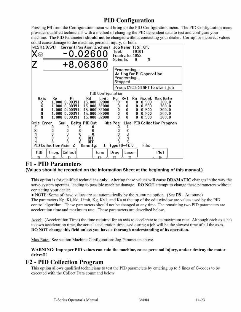
T-Series Operator’s Manual 3/4/04 14-23
PID Configuration Pressing F4 from the Configuration menu will bring up the PID Configuration menu. The PID Configuration menu provides qualified technicians with a method of changing the PID dependent data to test and configure your machine. The PID Parameters should not be changed without contacting your dealer. Corrupt or incorrect values could cause damage to the machine, personal injury, or both.
F1 - PID Parameters (Values should be recorded on the Information Sheet at the beginning of this manual.)
This option is for qualified technicians only. Altering these values will cause DRAMATIC changes in the way the servo system operates, leading to possible machine damage. DO NOT attempt to change these parameters without contacting your dealer. ● NOTE: Some of these values are set automatically by the Autotune option. (See F5 – Autotune) The parameters Kp, Ki, Kd, Limit, Kg, Kv1, and Ka at the top of the edit window are values used by the PID control algorithm. These parameters should not be changed at any time. The remaining two PID parameters are acceleration time and maximum rate. These parameters are described below. Accel: (Acceleration Time) the time required for an axis to accelerate to its maximum rate. Although each axis has its own acceleration time, the actual acceleration time used during a job will be the slowest time of all the axes. DO NOT change this field unless you have a thorough understanding of its operation. Max Rate: See section Machine Configuration: Jog Parameters above. WARNING: Improper PID values can ruin the machine, cause personal injury, and/or destroy the motor drives!!!
F2 - PID Collection Program This option allows qualified technicians to test the PID parameters by entering up to 5 lines of G-codes to be executed with the Collect Data command below.

14-24 3/4/04 T-Series Operator’s Manual
F3 - Collect Data This option allows qualified technicians to collect data on the movement of one of the motors. It uses the values located in the axis and density fields at the bottom of the menu and the PID collection program to collect the data. When this option is selected, the control executes the PID collection program and collects data on the selected axis. The information in the lower left hand side of the edit window provides information to qualified technicians about the selected axis.
F5 - Autotune This option is used by qualified technicians to automatically determine values for Max Rate, Accel/decel time, and Deadstart (See section Machine Configuration, earlier in this chapter) as well as the PID parameters for each installed axis. The Autotune procedure will make a series of moves on each axis, traveling up to 2" (see parameters 95-98) from the initial position in all directions to determine the friction and gravity of each axis. The initial high-speed move will use half of this distance. This will allow Autotune to work on axes with less than 4" of travel, on rotary axes that needs more than 1 degree to get up to speed, and on very fast/slow accelerating machines that need more than 1 inch to get up to speed. (In order to use less than 4", or more than 4 degrees, you must change the corresponding parameter.) ● NOTE: Do not run Autotune unless requested to do so by a qualified technician.
F6 - Drag This option is used by qualified technicians to determine whether your machine is binding anywhere along the axis travel. Press F6 to begin the drag test. Press F1 to select the axis you wish to check. Hit the CYCLE START button. A text file DRAG_X.OUT, or DRAG_Z.OUT file is generated and stored in the C:\CNC7T directory. If significant drag occurs, a message will be displayed on-screen. Contact your dealer to correct the problem as soon as possible
F7 - Laser This option is used by qualified technicians to take automated laser measurements and create or adjust the ballscrew compensation tables using accordingly. Do not attempt to run automatic laser compensation without first contacting your dealer for details.
F9 - Plot This option is used by qualified technicians to plot data collected under the F3 Collect button.

T-Series Operator’s Manual 3/4/04 14-25
Handwheel Configuration If you are using a manual input as a handwheel (MPG) input, be sure to configure all handwheel/MPG parameters. This list serves as a guide to configuration of the handwheels. Motor Parameters do not apply to MPG’s that use the special MPG input. You may configure any unused encoder input as a handwheel input. Screen Parameter Value Comments Jog Parameters
Travel (-), Travel (+) for an axis controlled by a handwheel.
Actual travel limits of the powered axis.
Axis controlled by a handwheel must have travel limits set.
Motor Parameters
Label M Handwheel input must be a manual axis.
Motor Parameters
Motor Revs/Unit Number of “clicks” per rev. If the wheel has no detents, use 100.
Motor Parameters
Encoder Counts/Rev Actual number of counts generated per rotation of the handwheel.
Use higher resolution encoders for smoother operation.
Motor Parameters
Lash, Limits, Homes 0, 0, 0 Do not apply to handwheels.
Motor Parameters
Direction reversed, Screw Compensation
N, N Do not apply to handwheels.
Machine Parameters
Parameter 19 – MPG Modes
As desired to select MPG on at power-up and MPG speed limit.
Be sure to enable or disable 100x operation here. See Machine Parameters for more information.
Machine Parameters
Parameter 40 – Basic Jog Increment
0.0001 in. or 0.002 mm by default.
This specifies the distance per “click” in x1 mode. Note: Also used for jogging.
Machine Parameters
Parameter 41 – Handwheel 100x Speed, User Jog Increment
Set to 100 for 100x movement. If this is too fast, choose a smaller value.
This speed will be used in 100x mode.
Machine Parameters
Parameter 128 – Handwheel Mapping
As needed to achieve the desired mapping.
See Machine Parameters for more information.
Machine Parameters
Parameter 129 – Handwheel Display
0 will work fine. Handwheel display will be suppressed.
See Machine Parameters for more information.
The distance per turn of the handwheel in 1x mode is determined by the following equation: Distance/Turn = Distance/Click * Clicks/Turn Parameter 40 is the distance/click. Motor parameter Revs/Unit holds the Clicks/Turn value. You may adjust the Clicks/Turn value to achieve a different distance per turn. For example, if Parameter 40 is 0.0001 inches and Clicks/Turn is 100, the distance per turn is 0.01 inches. To get 0.05 inches per turn, use 500 clicks per turn. (This assumes that the encoder counts per rev is accurate.)


T-Series Operator’s Manual 3/4/04 15-1
CHAPTER 15 CNC7 messages
Startup errors 101. Message: Error initializing graphics...
cannot continue (text mode). Cause: Missing GFT files or no VGA
adapter found. Effect: Exit CNC7 with return code 63.
'Fix files and try again' prompt from CNC7T4.BAT
Removed: By CNC7T4.BAT. 102. Message: Error initializing CPU7...
cannot continue (text mode). Cause: Error while sending CNC7.HEX
or CNC8.HEX. Other messages with more detail of error appear on screen before this message.
Effect: Exit CNC7 with return code 63. 'Fix files and try again' prompt from CNC7T4.BAT
Removed: By CNC7T4.BAT. 103. Message: Error sending setup
(windowed message). Cause: ESC key pressed while sending
setup. Effect: No setup command sent to
CPU7. CPU7 probably not responding.
Removed: Timed message. 104. Message: Error sending PID setup
(windowed message). Cause: ESC key pressed while sending
PID setup. Effect: No PID setup command sent to
CPU7. CPU7 probably not responding.
Removed: Timed message. 105. Message: CNC7.PLC file read error...
cannot continue (text mode). Cause: Missing or error in CNC7.PLC. Effect: Exit CNC7 with return code 63.
'Fix files and try again' prompt from CNC7T4.BAT
Removed: By CNC7T4.BAT.
106. Message: The PC clock appears to be wrong.
Cause: The time on the PC internal clock is earlier than the time recorded in a previously stored file.
Effect: None. Removed: Start of new job.
Messages issued upon exit 201. Message: Return code 60 (text mode). Cause: Utility button pressed
(CNC7T4.BAT probably not running).
Effect: Exit CNC7 with return code 60. Removed: By CNC7T4.BAT. 202. Message: Return code 61 (text mode). Cause: Edit button pressed
(CNC7T4.BAT probably not running).
Effect: Exit CNC7 with return code 61. Removed: By CNC7T4.BAT. 203. Message: Return code 62 (text mode). Cause: CAM button pressed
(CNC7T4.BAT probably not running).
Effect: Exit CNC7 with return code 62. Removed: By CNC7T4.BAT. 204. Message: Return code 63 (text mode). Cause: CPU7 not responding, or
CNC8.HEX, CNC7.PLC, or font file is missing or damaged.
Effect: Exit CNC7 with return code 63. Removed: By CNC7T4.BAT. 205. Message: Return code 64 (text mode). Cause: A floating-point math error
occurred. Effect: Exit CNC7 with return code 64. Removed: By CNC7T4.BAT. 206. Message: Return code 65 (text mode). Cause: CNC7.CFG file is missing or
damaged. Effect: Exit CNC7 with return code 65. Removed: By CNC7T4.BAT.

15-2 3/4/04 T-Series Operator’s Manual
Status messages 301. Message: Stopped. Cause: No operations in progress. Effect: None. 302. Message: Moving... Cause: Motors are moving while a CNC
program is running. Effect: None. 303. Message: Paused... Cause: Motion is paused while a CNC
program is running (FEED HOLD).
Effect: None. 304. Message: MDI... Cause: CPU7 running in MDI mode. Effect: None. 305. Message: Processing... Cause: CPU7 running in a mode other
than MDI. Effect: None. 306. Message: Job finished. Cause: Normal end of CNC program. Effect: None. 307. Message: Operator abort: job canceled. Cause: ESC or CYCLE CANCEL
pressed. Effect: Job canceled. Removed: Start of new job. 308. Message: Waiting for input #NN. Cause: M100 or M101 executing. Effect: Control pauses until specified
input changes state Removed: After input is received. 309. Prompt: Waiting for CYCLE START
button. Cause: M0, M1, M100/75, or Block
Mode. Effect: 'Block Mode' message displayed
if CNC program running in block mode.
Removed: After CYCLE START pressed.
310. Message: Waiting for output #NN. Cause: M100 or M101 executing. Effect: Control pauses until specified
output changes state Removed: After output is in correct state. 311. Message: Waiting for memory #NN. Cause: M100 or M101 executing. Effect: Control pauses until specified
memory bit changes state Removed: After memory is in correct state. 312. Message: Waiting for PLC operation
(Mnn). Cause: PLC program not clearing PLC
operation in progress. Effect: Control pauses until specified
PLC operation is complete Removed: After PLC program completes
operation in progress. 313. Message: Waiting for dwell time. Cause: G4 executing. Effect: Machine pauses for specified
amount of time. Removed: After specified time has elapsed. 314. Message: Input search data. Cause: Run/search key pressed. Effect: None. Removed: After search data input. 315. Message: Searching... Cause: Run/search in progress. Effect: None. 316. Message: Search complete. Processing Cause: Run/search mode. Search
successful. Preprocessing job. Effect: None. 317. Message: Waiting for automatic tool
change. Cause: M6 executing with automatic
tool changer. Effect: Control pauses until Automatic
Tool Change operation is complete
Removed: After changer signals that tool change is complete.

T-Series Operator’s Manual 3/4/04 15-3
Abnormal stops (faults) Abnormal stops are detected in the following order: PLC, servo drive, spindle drive, lube, ESTOP. This means that if both the servo drive and the spindle drive have faulted, the servo drive fault message would appear.
401. Message: PLC failure detected. Cause: CPU7 stopped with PLC failure
bit set. Effect: Job canceled. Removed: When PLC failure bit removed.
Typical implementation: correct PLC then press and release EMERGENCY STOP.
402. Message: PLC Online. Cause: PLC (RTK2) has returned on
line. Effect: None. 404. Message: Spindle drive fault detected. Cause: CPU7 stopped with spindle
drive fault bit set. Effect: Job canceled. Removed: when spindle drive fault
removed by PLC. Typical implementation: Check inverter for fault or reset spindle contactor OCR, then press and release EMERGENCY STOP.
405. Message: Lubricant level low. Cause: CPU7 stopped with low lube
fault bit set. Effect: Current job continues to run, but
a new job cannot be started. Removed: when low lube fault bit removed
by PLC. Typical implementation: add lube then press and release EMERGENCY STOP.
406. Message: Emergency Stop detected. Cause: CPU7 stopped with no fault bits
set. Effect: 'Fault: Job canceled.' prompt. Removed: when Emergency Stop released.
407. Message: X+ limit (#1) tripped. Cause: CPU7 stopped with limit switch
status. Effect: Job canceled. Removed: Start of new job, when limit
cleared. 408. Message: Programmed action timer
expired. Cause: M103 time expired before M104
encountered. Effect: Job canceled. Removed: Start of new job. 409. Message: _ axis lag. Cause: Lag Distance (Allowable
Following Error) exceeded on any axis for more than 1.5 seconds. Probably: 1.The machine is doing a very heavy cut. 2.The maximum rates or the acceleration values for the motors are set too high. 3.The motors are undersized for the application.
Effect: All axis motion is stopped and the CNC program is aborted.
Removed: 1.If the problem is occasional heavy cuts, slowing down the cutting feedrate can solve the problem. 2.If the problem only occurs on high speed moves then either the maximum speed or the acceleration is set too high. Lower the values in the Motor Setup menu or rerun Autotune again to determine new values. 3.If the problem is persistent lag errors in normal operations it indicates that the motors are too weak to handle the required loads. Increase the gear ratios or get more powerful motors.
Note: If the Lag Distance (Allowable Following Error) is exceeded for more than .025 seconds, then no acceleration will occur on any axis. However, no error message is generated at this point because no fatal error exists.

15-4 3/4/04 T-Series Operator’s Manual
410. Message: _ axis position error. Cause: A position error more than .25
inches is detected on any axis. Probably:
1.The motor is wired up backwards.
2.Noise is getting into the system via the motor cables (the line integrity has been violated).
3.An encoder error occurred. Effect: All axis motion is stopped,
power to the motors is released (all servo drive commands cease) and the CNC program is aborted.
Removed: Try a slow jog on the motor and watch the DRO position. If the position on the DRO goes opposite the direction indicated on the jog button, then the motor is wired up backwards. Change the motor wiring.
● Check the motor cabling paying particular attention to the ground connections. Replace the cable if it is damaged or repair the motor connections.
● Jog the motor awhile, at the maximum rate, using the fast jog buttons. (Check the fast jog rate in the motor jog parameters menu to make sure it is set equal to the maximum motor rate.) If the motor seems to jump around rather than accelerate and decelerate smoothly then you are probably fighting an encoder error.
● Swap the motor with one from another axis and see if the error follows the motor. If it stays with the axis, replace the CPU. If it follows the motor, replace the motor cable. If the problem still persists, replace the motor and encoder.
411. Message: _ axis full power without motion.
Cause: 90% Power (PID Output > 115) is applied to any axis and no motion >.0005 inches is detected, for more than the time specified in parameter 61 (usually .5 seconds). All axis motion is stopped and the CNC program is aborted.
Probably: ● One of the axes is against a
physical stop. ● The servo drive has shutdown
due to a limit switch input. ● The Z home switch is the
same as the Z + limit switch. Effect: All axis motion is stopped and
the CNC program is aborted. Removed: ● If the axis has obviously run
into a physical stop, use the slow jog mode to move the axis away from the end.
● Change the CNC program to remove moves that are out of bounds or re-zero to a point that permits the required CNC moves to be made.
● If the axis is not on a physical stop, check the limit switch to see if it is tripped. If it is then the software is commanding a move into the switch but the hardware is shutting the move down. Go to the motor setup menu and enter the limit switch if this is applicable.
● Make sure the switch input is not unstable or noisy. If it is then replace the switch. If the problem persists it may be necessary to create separate home and limit switch inputs.
● Use slow jog to move opposite the direction causing the error and clear all limit switches. Jog toward the direction causing the error, if no motion occurs then a servo drive failure is indicated.

T-Series Operator’s Manual 3/4/04 15-5
412. Message: _ axis encoder connection is bad.
Cause: Axis is enabled but a differential encoder signal is not detected. May indicate a loose or severed encoder cable or a bad encoder.
Effect: All axis motion is stopped and the CNC program is aborted.
Removed: Reconnect encoder or repair encoder and/or encoder cable.
413. Message: CPU Failure #01: power
down. Cause: CPU7 has experienced a
problem with the PC reset line. Effect: Power down, then power up the
system. The error should disappear.
Removed: Never - system must be powered down.
414. Message: CPU Failure #02: power down.
Cause: CPU7 detected CPU failure. Effect: Power down, then power up the
system. The error should disappear.
Removed: Never - system must be powered down.
415. Message: CPU fault #XX detected. Cause: invalid stop reason from CPU7. Effect: Power down, then power up the
system. The error should disappear.
Removed: Never - system must be powered down.
416. Message: Motion fault #XX detected. Cause: Invalid motion status from
CPU7. Effect: Power down, then power up the
system. The error should disappear.
Removed: never - system must be powered down.
417. Message: Abnormal end of job. Cause: Job ended without reason. Effect: Job canceled. Removed: Start of new job.
418. Message: Search data not found. Cause: Requested search input data not
found in loaded CNC file. Effect: Job canceled. Removed: Jogging, start of new job, other
error. 419. Message: Search line in embedded
subprogram. Cause: Requested search line is part of
an embedded subprogram; Search can only be used to start in the main program.
Effect: Job canceled. Removed: Start of new job. 420. Message: _ axis motor overheating. Cause: CNC7 estimates that a motor has
reached the warning temperature (set in Parameter 29).
Effect: No effect on a job which is currently running. However, a new job cannot be started until the motor has cooled below the warning temperature.
Removed: When next message appears. 421. Message: Motor(s) too hot: job canceled. Cause: CNC7 estimates that one or
more motors have reached the limit temperature (set in Parameter 30).
Effect: The current job is canceled and power is released.
Removed: Start of new job (after motors have cooled below warning temperature).
422. Message: Jog Panel Offline. Cause: Jog panel failure or loose cable. Effect: All buttons on jog panel are
inoperative. Removed: By reconnecting jog panel cable
and appearance of next message. 423. Message: Jog Panel Online. Cause: Loose jog panel cable has been
reconnected. Effect: All buttons on jog panel are
operative.
15-6 3/4/04 T-Series Operator’s Manual
424. Message: Feedrate Override Offline. Cause: Jog panel failure or loose cable. Effect: Feedrate knob and some jog
panel keys are inoperative. Removed: By appearance of next message. 425. Message: Feedrate Override Online. Cause: Loose jog panel cable has been
reconnected. Effect: Feedrate Override knob is
operative. 426. Message: Spindle Override Offline. Cause: Jog panel failure or loose cable. Effect: Spindle knob and some jog
panel keys are inoperative. Removed: By appearance of next message. 427. Message: Spindle Override Online. Cause: Loose jog panel cable has been
reconnected. Effect: Spindle Override knob is
operative. 428. Message: MPG Offline. Cause: MPG failure or loose cable. Effect: MPG is inoperative. Removed: By reconnecting MPG cable and
appearance of next message. 429. Message: MPG Online. Cause: Loose MPG cable has been
reconnected. Effect: MPG is operative. 430. Message: CPU7 PIC Offline. Cause: Power supply or hardware
problem. Effect: Power down, then power up the
system. The error should disappear.
431. Message: CPU7 PIC Online. Cause: CPU7 is back on line. Effect: None. 432. Message: External PLC Offline. Cause: Koyo PLC Direct failure or
loose cable. Effect: None. Removed: When PLC failure removed or
cable reconnected.
433. Message: External PLC Online. Cause: PLC failure corrected. Effect: None. 434. Message: _ idling too high: Releasing
power. Cause: Axis is not moving and no job is
running but axis has stopped against some abnormal resistance.
Effect: Power to motors is released. Removed: Start of new job. 435. Message: _ axis runaway: Check motor
wiring. Cause: Axis was moving more than 120
in/min while power was supposed to be off. Motor may be wired backwards or may be a shorted servo drive.
Effect: Power to motors is released. Removed: Start of new job (after wiring or
servo drive failure has been removed).
436. Message: Servo drive shutdown. Cause: This error message is produced
by hardware detection of a physical error.
The servo drive hardware originates this error message if it detects either an over-current or over-voltage condition. The particular hardware condition is reflected on the servo drive LEDs. Once the servo drive detects this error condition it stops all motion and removes power to the motors. The hardware indicates the presence of this condition to the CNC7 software via the servo drive fault input to the PLC.
Effect: Power to motors is released. Removed: The particular condition can be
resolved by observing the servo drive LEDs. This message is removed and the condition is reset only if the ESTOP is pressed and released. The PLC program that is responsible for latching this condition is also responsible for clearing this condition.
T-Series Operator’s Manual 3/4/04 15-7
439. Message: %c axis servo drive processor failure
Cause: Logic power failure or processor failure
Effect: No motor power Removed: Power complete unit down and
check connections to drive. 441. Message: %c axis over-voltage Cause: Drive input power greater than
350 vdc. Effect: No motor power Removed: Check input voltage; cycle start. 442. Message: %c axis under-voltage Cause: Drive input power less than 80
vdc. Effect: No motor power Removed: Check input voltage; cycle start. 443. Message: %c axis commutation encoder
bad Cause: Bad connection from encoder. Effect: No motor power Removed: Check encoder cable; cycle
input power. 444. Message: %c axis over-temperature
detected Cause: Drive over temp sensor tripped. Effect: No motor power Removed: Wait for drive to cool and cycle
start. 445. Message: %c axis over-current detected Cause: Over-current detected on axis Effect: No motor power Removed: Check motor power connection;
cycle start. 446. Message: %c axis synchronization
failure Cause: Communication checksum error Effect: No motor power Removed: Check fiber optic cables.
CNC syntax errors 501. Message: Invalid character on line
NNNNN. Cause: Invalid character on CNC line. Effect: Job canceled. Removed: Start of new job.
502. Message: Invalid G code on line NNNNN.
Cause: Invalid G code encountered on CNC line.
Effect: Job canceled. Removed: Start of new job. 503. Message: Invalid M function on line
NNNNN. Cause: Invalid M function encountered
on CNC line. Effect: Job canceled. Removed: Start of new job. 504. Message: Invalid parameter on line
NNNNN. Cause: Invalid or missing number after
letter. Effect: Job canceled. Removed: Start of new job. 505. Message: Invalid value on line NNNNN. Cause: Value out of range (T, H, D). Effect: Job canceled. Removed: Start of new job. 506. Message: Only 1 M code per line. Cause: More than one M code appears
on the line. Effect: Job canceled. Removed: Start of new job. 507. Message: No closing quote. Cause: The closing quotation mark (“)
in a quoted string is missing. Effect: Job canceled. Removed: Start of new job. 508. Message: Macro nesting too deep. Cause: Macro nesting limit exceeded on
attempt to invoke a subroutine. Effect: Job canceled. Removed: Start of new job. 509. Message: Option not available. Cause: Attempt to access a locked
software option. Effect: Job canceled. Removed: Start of new job. 510. Message: Too many macro arg’s.

15-8 3/4/04 T-Series Operator’s Manual
Cause: Too many arguments were given in a G65 macro call.
Effect: Job canceled. Removed: Start of new job. 511. Message: Missing parameter. Cause: A parameter is required or
expected but not found. Effect: Job canceled. Removed: Start of new job. 512. Message: X not set for selected WCS. Cause: The selected WCS does not have
a value set for X. Effect: Job canceled. Removed: Start of new job. 513. Message: Expected “=”. Cause: Error in expression to left of
“=”, missing “=”, or orphaned parameter.
Effect: Job canceled. Removed: Start of new job. 514. Message: Empty expression. Cause: The expression contains no
operands. Effect: Job canceled. Removed: Start of new job. 515. Message: Syntax error in expression. Cause: Illegal character in number,
variable or function. Effect: Job canceled. Removed: Start of new job. 516. Message: Unmatched bracket
(parenthesis). Cause: Brackets or parentheses are
paired improperly or misplaced. Effect: Job canceled. Removed: Start of new job. 517. Message: Evaluation stack overflow. Cause: Brackets or parentheses are
nested too deeply. Effect: Job canceled. Removed: Start of new job. 518. Message: Undefined variable. Cause: The variable name does not
exist. Effect: Job canceled. Removed: Start of new job. 519. Message: Too many variables.
Cause: The space allotted for user-defined variables has been exceeded.
Effect: Job canceled. Removed: Start of new job. 520. Message: Invalid variable name. Cause: The variable name contains an
illegal character. Effect: Job canceled. Removed: Start of new job. 521. Message: Divide by zero. Cause: Attempt to divide by zero. Effect: Job canceled. Removed: Start of new job. 522. Message: Domain error. Cause: Imaginary number would result
(square root of a negative number).
Effect: Job canceled. Removed: Start of new job. 523. Message: Invalid value in assignment. Cause: Attempt to assign an illegal
value to a system variable. Effect: Job canceled. Removed: Start of new job. 524. Message: Variable is read-only. Cause: Attempt to assign a value to a
read-only system variable. Effect: Job canceled. Removed: Start of new job.

T-Series Operator’s Manual 3/4/04 15-9
Cutter compensation errors 601. Message: Error: no compensation in
MDI. Cause: G41 or G42 entered in MDI. Effect: MDI is not canceled, but cutter
compensation does NOT go into effect. Remainder of line processed.
602. Message: Arc as first comp. move on line
NNNNN. Cause: Cutter compensation started with
arc as first move. Effect: Job canceled. Removed: Start of new job. 603. Message: Arc as first uncomp. move on
line NNNNN. Cause: Arc specified as first move after
end of compensation (G40). Effect: Job canceled. Removed: Start of new job. 604. Message: Plane must be XY on line
NNNNN. Cause: Cutter compensation started with
YZ or ZX plane selected. Effect: Job canceled. Removed: Start of new job. 605. Message: Canned cycle not allowed on
line NNNNN. Cause: Canned cycle attempted during
compensation. Effect: Job canceled. Removed: Start of new job. 606. Message: G53 not allowed on line
NNNNN. Cause: G53 attempted during
compensation. Effect: Job canceled. Removed: Start of new job. 607. Message: Set home not allowed on line
NNNNN. Cause: M26 attempted during
compensation. Effect: Job canceled. Removed: Start of new job.
608. Message: Ref. point move not allowed on line NNNNN.
Cause: G28, G29, or G30 attempted during compensation.
Effect: Job canceled.
Parameter setting errors 701. Message: G10 error: no R-value on line
NNNNN. Cause: G10 used with no R-value. Effect: Job canceled. Removed: Start of new job 702. Message: G10 error: invalid D on line
NNNNN. Cause: G10 D0 Rxx specified. Effect: Job canceled (D0 cannot be set;
it is always zero). Removed: Start of new job. 703. Message: G10 error: invalid H on line
NNNNN. Cause: G10 H0 Rxx specified. Effect: Job canceled (H0 cannot be set;
it is always zero). Removed: Start of new job. 704. Message: G10 error: invalid P on line
NNNNN. Cause: G10 used with unknown P
value. Effect: Job canceled. Removed: Start of new job. 705. Message: G10 error: No D, H, or P on
line NNNNN. Cause: G10 used without D, H, or P to
assign value. Effect: Job canceled. Removed: Start of new job.
Miscellaneous errors 901. Message: Ref. point invalid on line
NNNNN. Cause: G30 with invalid P value (must
be 1 or 2). Effect: Job canceled. Removed: Start of new job.

15-10 3/4/04 T-Series Operator’s Manual
902. Message: No prior G28 or G30 on line NNNNN.
Cause: G29 with no preceding G28 or G30.
Effect: Job canceled. Removed: Start of new job. 903. Message: Warning: No coordinates for
G92 on line NNNNN. Cause: G92 with no axis coordinates to
set. Effect: Remainder of line processed; job
continues. Removed: When next message appears. 904. Message: Invalid plane for arc on line
NNNNN. Cause: I, J, or K specified with wrong
plane (e.g. K with G17, or I with G19).
Effect: Job canceled. Removed: Start of new job. 905. Message: Warning: 0 radius arc on line
NNNNN. Cause: Arc move was specified with
zero radius. Effect: Move is done as a linear move;
job continues. Removed: When next message appears. 906. Message: Warning: unknown arc on line
NNNNN. Cause: Position of arc move could not
be determined from parameters (e.g. G91 G2 X0 Y0 R1).
Effect: Move is done as a linear move; job continues.
Removed: When next message appears. 907. Message: _ axis travel exceeded on line
NNNNN. Cause: Software travel limit would be
exceeded by the requested move. Effect: Job canceled. Removed: Start of new job. 908. Message: Option not available on line
NNNNN. Cause: A code for an extra-cost option
was specified, but the option has not been licensed.
Effect: Job canceled. Removed: Start of new job.
909. Message: Program too long: job canceled.
Cause: Attempt to run a job over 640K in length, without the unlimited program size option.
Effect: Job canceled. Removed: Start of new job. 910. Message: No subroutines in MDI. Cause: Specified O9100 - O9999 in
MDI, which would begin an embedded subprogram.
Effect: MDI canceled. Removed: Start of new job. 911. Message: Illegal recursion. Cause: Attempt to execute a
subprogram or macro that calls itself, either directly or indirectly.
Effect: Job canceled. Removed: Start of new job. 912. Message: Too many subprogram calls. Cause: Attempt to run a job with 20 or
more levels of subprogram nesting.
Effect: Job canceled. Removed: Start of new job. 913. Message: Could not open file
filename.ext. Cause: Attempt to call a subprogram or
macro, but the subprogram file does not exist.
Effect: Job canceled. Removed: Start of new job. 1100 – 1199. Custom messages defined in
CNC7XMSG.TXT. Please contact your dealer if you have any questions regarding a particular message.

T-Series Operator’s Manual 3/4/2004 7-1