centrifugal roof supply fan - air movement and control ... · pdf filecentrifugal roof supply...
TRANSCRIPT
Centrifugal Roof Supply FanModel SAFBelt Drive
BU
IL
DI
NG
V
AL
UE
I
N
AI
R.
July2010
Model SAF - Supply Air Fan
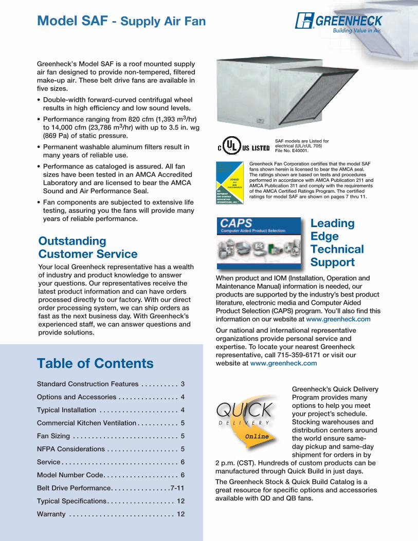
Greenheck’s Model SAF is a roof mounted supply air fan designed to provide non-tempered, filtered make-up air. These belt drive fans are available in five sizes.
• Double-width forward-curved centrifugal wheel results in high efficiency and low sound levels.
• Performance ranging from 820 cfm (1,393 m3/hr) to 14,000 cfm (23,786 m3/hr) with up to 3.5 in. wg (869 Pa) of static pressure.
• Permanent washable aluminum filters result in many years of reliable use.
• Performance as cataloged is assured. All fan sizes have been tested in an AMCA Accredited Laboratory and are licensed to bear the AMCA Sound and Air Performance Seal.
• Fan components are subjected to extensive life testing, assuring you the fans will provide many years of reliable performance.
2
Standard Construction Features . . . . . . . . . . 3
Options and Accessories . . . . . . . . . . . . . . . . 4
Typical Installation . . . . . . . . . . . . . . . . . . . . . 4
Commercial Kitchen Ventilation . . . . . . . . . . . 5
Fan Sizing . . . . . . . . . . . . . . . . . . . . . . . . . . . . 5
NFPA Considerations . . . . . . . . . . . . . . . . . . . 5
Service . . . . . . . . . . . . . . . . . . . . . . . . . . . . . . . 6
Model Number Code. . . . . . . . . . . . . . . . . . . . 6
Belt Drive Performance. . . . . . . . . . . . . . . .7-11
Typical Specifications . . . . . . . . . . . . . . . . . . 12
Warranty . . . . . . . . . . . . . . . . . . . . . . . . . . . . 12
Table of Contents
Outstanding Customer ServiceYour local Greenheck representative has a wealth of industry and product knowledge to answer your questions. Our representatives receive the latest product information and can have orders processed directly to our factory. With our direct order processing system, we can ship orders as fast as the next business day. With Greenheck’s experienced staff, we can answer questions and provide solutions.
LeadingEdge Technical Support
When product and IOM (Installation, Operation and Maintenance Manual) information is needed, our products are supported by the industry’s best product literature, electronic media and Computer Aided Product Selection (CAPS) program. You’ll also find this information on our website at www.greenheck.com
Our national and international representative organizations provide personal service and expertise. To locate your nearest Greenheck representative, call 715-359-6171 or visit our website at www.greenheck.com
Greenheck’s Quick Delivery Program provides many options to help you meet your project’s schedule. Stocking warehouses and distribution centers around the world ensure same-day pickup and same-day shipment for orders in by
2 p.m. (CST). Hundreds of custom products can be manufactured through Quick Build in just days.
The Greenheck Stock & Quick Build Catalog is a great resource for specific options and accessories available with QD and QB fans.
RAPIDAAPIE N T R E G AE N T R E G AT RE N T R E G AE N T R E G AT R E
RAPIDAE N T R E G AE N T R E G AT RE N T R E G AE N T R E G AT R E
Greenheck Fan Corporation certifies that the model SAF fans shown herein is licensed to bear the AMCA seal. The ratings shown are based on tests and procedures performed in accordance with AMCA Publication 211 and AMCA Publication 311 and comply with the requirements of the AMCA Certified Ratings Program. The certified ratings for model SAF are shown on pages 7 thru 11.
SAF models are Listed for electrical (UL/cUL 705) File No. E40001.
3
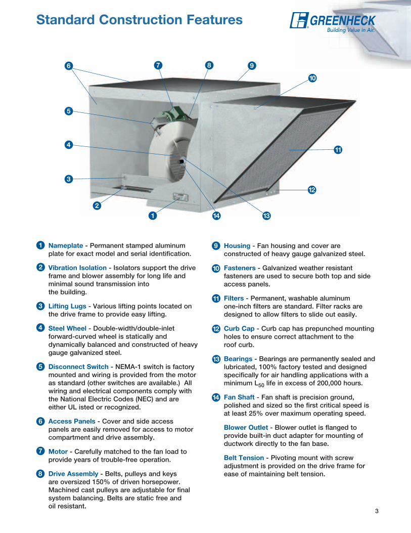
Standard Construction Features
Nameplate - Permanent stamped aluminum plate for exact model and serial identification.
Vibration Isolation - Isolators support the drive frame and blower assembly for long life and minimal sound transmission into the building.
Lifting Lugs - Various lifting points located on the drive frame to provide easy lifting.
Steel Wheel - Double-width/double-inlet forward-curved wheel is statically and dynamically balanced and constructed of heavy gauge galvanized steel.
Disconnect Switch - NEMA-1 switch is factory mounted and wiring is provided from the motor as standard (other switches are available.) All wiring and electrical components comply with the National Electric Codes (NEC) and are either UL isted or recognized.
Access Panels - Cover and side access panels are easily removed for access to motor compartment and drive assembly.
Motor - Carefully matched to the fan load to provide years of trouble-free operation.
Drive Assembly - Belts, pulleys and keys are oversized 150% of driven horsepower. Machined cast pulleys are adjustable for final system balancing. Belts are static free and oil resistant.
1
2
3
4
5
6
7
8
9
10
11
12
13
14
Housing - Fan housing and cover are constructed of heavy gauge galvanized steel.
Fasteners - Galvanized weather resistant fasteners are used to secure both top and side access panels.
Filters - Permanent, washable aluminum one-inch filters are standard. Filter racks are designed to allow filters to slide out easily.
Curb Cap - Curb cap has prepunched mounting holes to ensure correct attachment to the roof curb.
Bearings - Bearings are permanently sealed and lubricated, 100% factory tested and designed specifically for air handling applications with a minimum L50 life in excess of 200,000 hours.
Fan Shaft - Fan shaft is precision ground, polished and sized so the first critical speed is at least 25% over maximum operating speed.
Blower Outlet - Blower outlet is flanged to provide built-in duct adapter for mounting of ductwork directly to the fan base.
Belt Tension - Pivoting mount with screw adjustment is provided on the drive frame for ease of maintaining belt tension.
3
4
5
6 7 8 9
10
11
12
13141
2
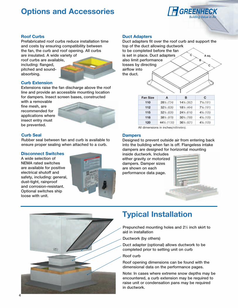
Options and Accessories
4
Disconnect Switches A wide selection of NEMA rated switches are available for positive electrical shutoff and safety, including: general, dust-tight, rainproof and corrosion-resistant. Optional switches ship loose with unit.
Curb ExtensionExtensions raise the fan discharge above the roof line and provide an accessible mounting location for dampers. Insect screen bases, constructed with a removable fine mesh, are recommended for applications where insect entry must be prevented.
Curb Seal Rubber seal between fan and curb is available to ensure proper sealing when attached to a curb.
Roof CurbsPrefabricated roof curbs reduce installation time and costs by ensuring compatibility between the fan, the curb and roof opening. All curbs are insulated. A wide variety of roof curbs are available, including: flanged, pitched and sound-absorbing.
A sq.C
C
B
DampersDesigned to prevent outside air from entering back into the building when fan is off. Flangeless intake dampers are designed for horizontal mounting inside ductwork. Includes either gravity or motorized dampers. Damper sizes are shown on each performance data page.
Fan Size A B C
110 281⁄2 (724) 141⁄4 (362) 71⁄8 (181)
112 321⁄2 (826) 181⁄4 (464) 71⁄8 (181)
115 321⁄2 (826) 241⁄4 (616) 41⁄8 (105)
118 381⁄2 (978) 301⁄4 (768) 41⁄8 (105)
120 441⁄2 (1130) 361⁄4 (921) 41⁄8 (105)
Prepunched mounting holes and 21⁄2 inch skirt to aid in installation
Ductwork (by others)
Duct adapter (optional) allows ductwork to be completed prior to setting unit on curb
Roof curb
Roof opening dimensions can be found with the dimensional data on the performance pages.
Note: In cases where extreme snow depths may be encountered, a curb extension may be required to raise unit or condensation pans may be required in ductwork.
Typical Installation
Duct AdaptersDuct adapters fit over the roof curb and support the top of the duct allowing ductwork to be completed before the fan is set in place. Duct adapters also limit performance losses by directing airflow into the duct.
All dimensions in inches(millimeters).
5
Commercial Kitchen Ventilation
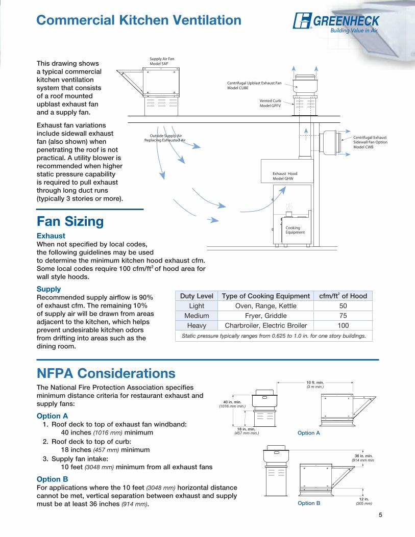
NFPA ConsiderationsThe National Fire Protection Association specifies minimum distance criteria for restaurant exhaust and supply fans:
Option A 1. Roof deck to top of exhaust fan windband:
40 inches (1016 mm) minimum 2. Roof deck to top of curb:
18 inches (457 mm) minimum 3. Supply fan intake:
10 feet (3048 mm) minimum from all exhaust fans
Option BFor applications where the 10 feet (3048 mm) horizontal distance cannot be met, vertical separation between exhaust and supply must be at least 36 inches (914 mm).
40 in. min.
18 in. min.
10 ft. min.
36 in. min.
12 in.
(3 m min.)
(914 mm min.)
(305 mm)
(1016 mm min.)
(457 mm min.)
40 in. min.
18 in. min.
10 ft. min.
36 in. min.
12 in.
(3 m min.)
(914 mm min.)
(305 mm)
(1016 mm min.)
(457 mm min.)
Sidewall ExhaustFan
Exhaust OnlyHood
Centrifugal Upblast Exhaust FanModel CUBE
Vented CurbModel GPFV
Exhaust HoodModel GHW
Supply Air FanModel SAF
Outside Supply AirReplacing Exhausted Air
Centrifugal ExhaustSidewall Fan OptionModel CWB
CookingEquipment
Option A
Option B
This drawing shows a typical commercial kitchen ventilation system that consists of a roof mounted upblast exhaust fan and a supply fan.
Exhaust fan variations include sidewall exhaust fan (also shown) when penetrating the roof is not practical. A utility blower is recommended when higher static pressure capability is required to pull exhaust through long duct runs (typically 3 stories or more).
Fan SizingExhaustWhen not specified by local codes, the following guidelines may be used to determine the minimum kitchen hood exhaust cfm. Some local codes require 100 cfm/ft2 of hood area for wall style hoods.
SupplyRecommended supply airflow is 90% of exhaust cfm. The remaining 10% of supply air will be drawn from areas adjacent to the kitchen, which helps prevent undesirable kitchen odors from drifting into areas such as the dining room.
Duty Level Type of Cooking Equipment cfm/ft2 of HoodLight Oven, Range, Kettle 50
Medium Fryer, Griddle 75Heavy Charbroiler, Electric Broiler 100
Static pressure typically ranges from 0.625 to 1.0 in. for one story buildings.

SAF - 110 - 7
MODEL CONFIGURATION
SAF - Belt Drive Supply
NOMINAL WHEEL DIAMETER IN INCHES
FAN SIzE110 through 120
MOTOR HP 7 = 3/4 30 = 34 = 1/4 10 = 1 50 = 53 = 1/3 15 = 11⁄2 75 = 71⁄25 = 1/2 20 = 2 100 = 10
Model Number CodeThe model number system is designed to completely identify the fan. The correct code letters must be specified to designate belt or direct drive. The remainder of the model number is determined by the size and performance selected from the following pages.
Filtered supply fans require regular inspection and cleaning (or replacement) of filters to ensure high efficiency and performance. The model SAF is designed to provide easy access to filters and other components through a convenient removable hood cover.
Weather Resistant Fasteners Easy to remove galvanized fasteners keep the hood cover secured.
Filter Removal Filter racks are designed so filters can easily slide out for cleaning or replacement.
Removable Hood Cover Removal of the hood cover allows easy access to all fan components for inspection, cleaning, and service.
ServiceabilityThe internal drive components are easy to reach and service with the hood removed.
6
Service

Inlet
Airflow
119/16 (294)
211/16
(535)
11/2 (38)
133/8(340)
91/4(235)
25(635)
22(559)
81/4 (210)
30(762)
30(762)
7
SAF-110
Do not select t
o the le
ft of t
his s
yste
m c
urve
cfm
ModelNumber
FanCFM
Static Pressure in inches wg0.125 0.25 0.375 0.5 0.625 0.75 1 1.125 1.25 1.5
SAF-110
820RPM 432 549BHP 0.05 0.08
Sones 11.4 11.9
1000RPM 476 579 672 755BHP 0.07 0.11 0.14 0.17
Sones 10.0 11.7 11.3 10.5
1180RPM 525 616 701 780 850BHP 0.11 0.14 0.18 0.22 0.26
Sones 10.5 11.2 11.5 11.2 11.2
1360RPM 577 660 736 809 878 941BHP 0.15 0.19 0.23 0.28 0.32 0.37
Sones 11.2 11.0 11.4 11.4 11.8 12.7
1540RPM 632 707 777 844 908 969 1082 1134 1192BHP 0.21 0.25 0.30 0.35 0.40 0.45 0.55 0.60 0.66
Sones 12.0 11.7 11.7 11.8 12.7 13.7 15.2 18.3 19.5
1720RPM 688 757 822 883 943 1001 1110 1162 1210 1307BHP 0.28 0.33 0.38 0.43 0.48 0.54 0.65 0.71 0.77 0.89
Sones 13.1 12.8 12.4 12.8 13.9 14.9 17.9 18.9 19.9 22
1900RPM 745 809 870 927 982 1036 1140 1189 1238 1328BHP 0.37 0.42 0.48 0.53 0.59 0.65 0.77 0.83 0.90 1.02
Sones 14.2 14.1 13.7 14.5 15.4 16.4 18.6 19.5 20 23
2080RPM 802 864 920 974 1026 1075 1174 1221 1266BHP 0.47 0.53 0.59 0.65 0.71 0.77 0.90 0.97 1.04
Sones 15.5 15.7 15.9 16.5 17.3 18.2 20 21 21
2260RPM 859 920 971 1023 1071 1119 1210BHP 0.59 0.66 0.71 0.78 0.85 0.92 1.05
Sones 16.9 17.6 18.1 18.6 19.4 21 22
2440RPM 918 976 1025 1073 1120
BHP 0.72 0.80 0.87 0.94 1.01Sones 18.8 19.6 20 21 22
2620RPM 977 1032 1080BHP 0.88 0.97 1.04
Sones 21 22 23
MAXIMUM RPM = 1400TIP SPEED = RPM x 2.91
MAXIMUM MOTOR FRAME SIZE = 145TAVERAGE OUTLET VELOCITY = CFM/1.07
Damper Size = 14 x 14 (355 x 355)Roof Opening = 161/2 x 161/2 (419 x 419)Curb Cap Thickness = 0.052 (1)^Approximate Unit Weight = 181 lb. (82 kg)
All dimensions in inches (millimeters). ^Weight shown is largest cataloged Open Drip Proof motor.
Performance certified is for installation type B: free inlet, ducted outlet. Power rating (Bhp) does not include transmission losses. Performance ratings include the effects of a filter.
The sound ratings shown are loudness values in fan sones at 5 ft. (1.5 m) in a hemispherical free field calculated per AMCA Standard 301. Values shown are for installation type B: free inlet hemispherical sone levels.
Inlet
Airflow
1311/16 (348)
27 3/8(695)
2 (51)
159/16
(395)
1011/16
(271)
32(814)
91/2 (241)
34(864)
34(864)
291/4(743)
1/16
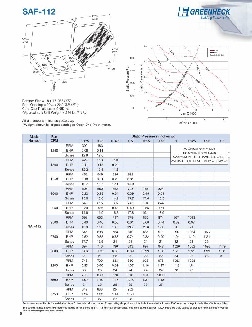
SAF-112
8
Damper Size = 18 x 18 (457 x 457)Roof Opening = 201/2 x 201/2 (521 x 521)Curb Cap Thickness = 0.052 (1)^Approximate Unit Weight = 244 lb. (111 kg)
All dimensions in inches (millimeters). ^Weight shown is largest cataloged Open Drip Proof motor.
ModelNumber
FanCFM
Static Pressure in inches wg0.125 0.25 0.375 0.5 0.625 0.75 1 1.125 1.25 1.5
SAF-112
1250RPM 390 483BHP 0.08 0.11
Sones 12.8 12.6
1500RPM 422 513 590BHP 0.11 0.15 0.20
Sones 12.2 12.5 11.8
1750RPM 459 549 616 682BHP 0.16 0.21 0.26 0.31
Sones 12.7 12.7 12.1 14.0
2000RPM 503 580 652 708 766 824BHP 0.22 0.28 0.34 0.39 0.45 0.51
Sones 13.6 13.6 14.2 15.7 17.6 18.3
2250RPM 549 615 685 745 794 844BHP 0.30 0.36 0.43 0.49 0.55 0.61
Sones 14.6 14.9 16.6 17.8 19.1 18.9
2500RPM 598 653 717 779 830 874 967 1013BHP 0.40 0.46 0.53 0.61 0.68 0.74 0.89 0.97
Sones 15.8 17.0 18.8 19.7 19.8 19.6 20 21
2750RPM 647 698 753 810 865 911 990 1034 1077BHP 0.52 0.58 0.66 0.74 0.82 0.90 1.04 1.12 1.21
Sones 17.7 19.9 21 21 21 21 22 23 25
3000RPM 697 743 790 843 897 947 1026 1062 1098 1179BHP 0.66 0.73 0.80 0.89 0.99 1.08 1.23 1.31 1.39 1.58
Sones 20 21 23 22 22 22 24 25 26 31
3250RPM 748 790 833 880 928 978 1063 1098BHP 0.83 0.90 0.98 1.07 1.16 1.27 1.45 1.54
Sones 22 23 24 24 24 24 26 27
3500RPM 798 839 878 918 964 1009BHP 1.02 1.10 1.18 1.26 1.37 1.48
Sones 24 25 25 25 26 27
3750RPM 849 888 924 962BHP 1.24 1.33 1.41 1.50
Sones 26 27 27 28
Do not select t
o th
e left
of thi
s sys
tem
cur
ve
cfm
MAXIMUM RPM = 1200TIP SPEED = RPM x 3.30
MAXIMUM MOTOR FRAME SIZE = 145TAVERAGE OUTLET VELOCITY = CFM/1.48
Performance certified is for installation type B: free inlet, ducted outlet. Power rating (Bhp) does not include transmission losses. Performance ratings include the effects of a filter.
The sound ratings shown are loudness values in fan sones at 5 ft. (1.5 m) in a hemispherical free field calculated per AMCA Standard 301. Values shown are for installation type B: free inlet hemispherical sone levels.
Inlet
Airflow
161/16 (408)
273/8(695)
91/16
(230)
321/16
(814)
291/4(743)
81/2 (216)
34(864)
34(864)
2 (51)
1813/16
(478)
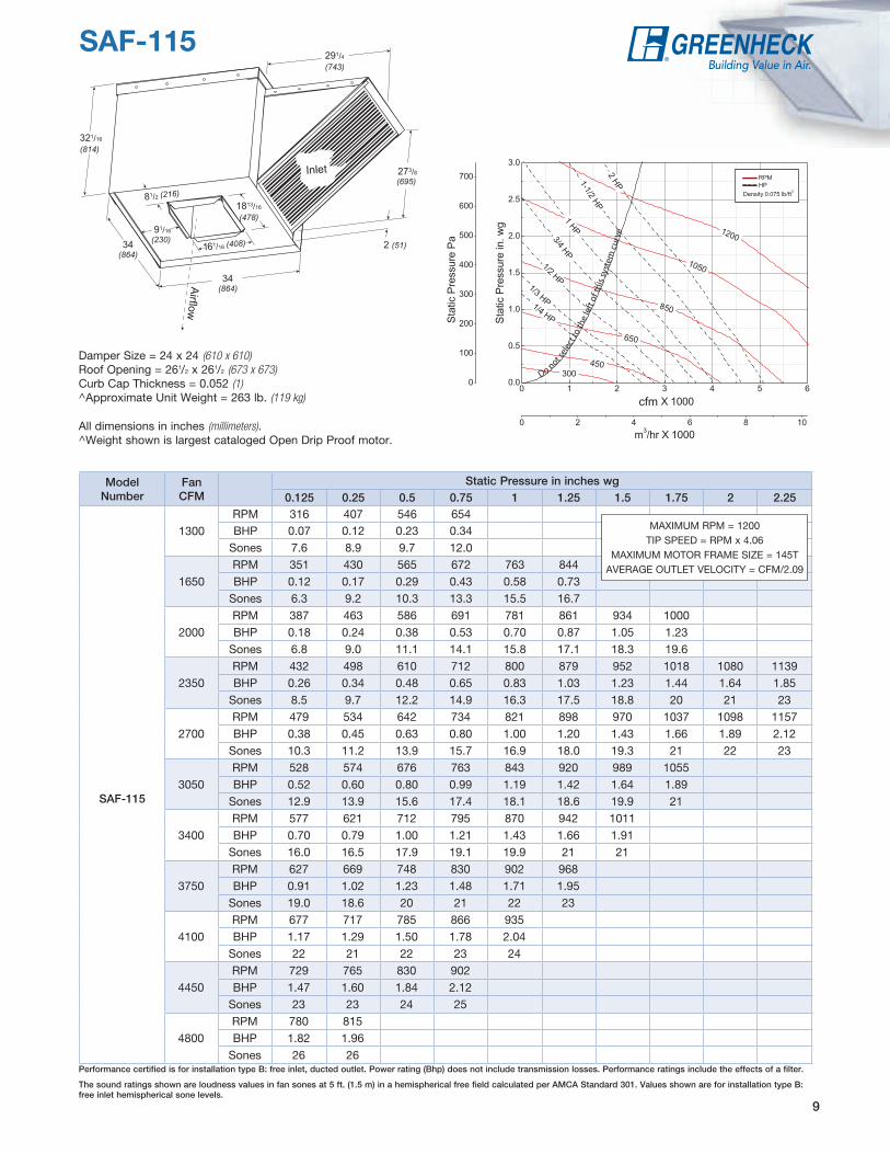
SAF-115
Do not sel
ect t
o th
e le
ft o
f thi
s sy
stem
cur
ve
cfm
ModelNumber
FanCFM
Static Pressure in inches wg0.125 0.25 0.5 0.75 1 1.25 1.5 1.75 2 2.25
SAF-115
1300RPM 316 407 546 654BHP 0.07 0.12 0.23 0.34
Sones 7.6 8.9 9.7 12.0
1650RPM 351 430 565 672 763 844BHP 0.12 0.17 0.29 0.43 0.58 0.73
Sones 6.3 9.2 10.3 13.3 15.5 16.7
2000RPM 387 463 586 691 781 861 934 1000BHP 0.18 0.24 0.38 0.53 0.70 0.87 1.05 1.23
Sones 6.8 9.0 11.1 14.1 15.8 17.1 18.3 19.6
2350RPM 432 498 610 712 800 879 952 1018 1080 1139BHP 0.26 0.34 0.48 0.65 0.83 1.03 1.23 1.44 1.64 1.85
Sones 8.5 9.7 12.2 14.9 16.3 17.5 18.8 20 21 23
2700RPM 479 534 642 734 821 898 970 1037 1098 1157BHP 0.38 0.45 0.63 0.80 1.00 1.20 1.43 1.66 1.89 2.12
Sones 10.3 11.2 13.9 15.7 16.9 18.0 19.3 21 22 23
3050RPM 528 574 676 763 843 920 989 1055BHP 0.52 0.60 0.80 0.99 1.19 1.42 1.64 1.89
Sones 12.9 13.9 15.6 17.4 18.1 18.6 19.9 21
3400RPM 577 621 712 795 870 942 1011BHP 0.70 0.79 1.00 1.21 1.43 1.66 1.91
Sones 16.0 16.5 17.9 19.1 19.9 21 21
3750RPM 627 669 748 830 902 968BHP 0.91 1.02 1.23 1.48 1.71 1.95
Sones 19.0 18.6 20 21 22 23
4100RPM 677 717 785 866 935BHP 1.17 1.29 1.50 1.78 2.04
Sones 22 21 22 23 24
4450RPM 729 765 830 902BHP 1.47 1.60 1.84 2.12
Sones 23 23 24 25
4800RPM 780 815BHP 1.82 1.96
Sones 26 26
9
MAXIMUM RPM = 1200TIP SPEED = RPM x 4.06
MAXIMUM MOTOR FRAME SIZE = 145TAVERAGE OUTLET VELOCITY = CFM/2.09
Damper Size = 24 x 24 (610 x 610)Roof Opening = 261/2 x 261/2 (673 x 673)Curb Cap Thickness = 0.052 (1)^Approximate Unit Weight = 263 lb. (119 kg)
All dimensions in inches (millimeters). ^Weight shown is largest cataloged Open Drip Proof motor.
Performance certified is for installation type B: free inlet, ducted outlet. Power rating (Bhp) does not include transmission losses. Performance ratings include the effects of a filter.
The sound ratings shown are loudness values in fan sones at 5 ft. (1.5 m) in a hemispherical free field calculated per AMCA Standard 301. Values shown are for installation type B: free inlet hemispherical sone levels.
Inlet
Airflow
191/8 (486)
311/16
(789)
2 (51)
225/16
(567)
115/16
(287)
361/16
(916)
32
(813)
93/4 (248)
40(1016)
40(1016)
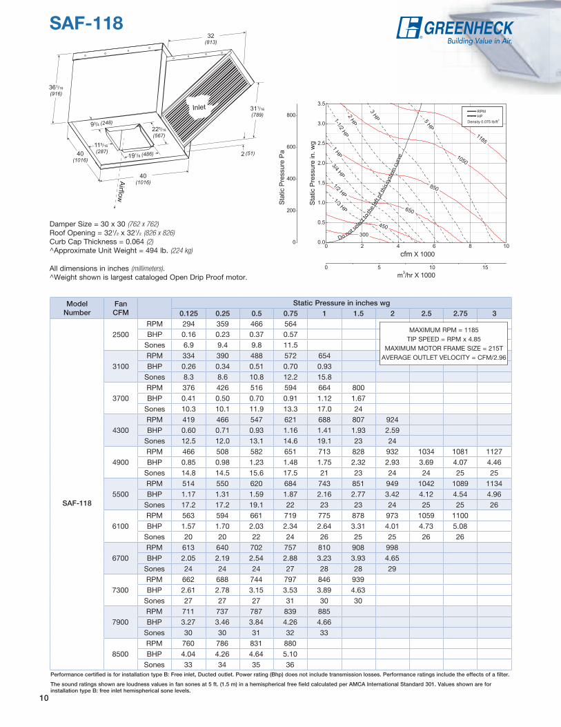
SAF-118
10
Damper Size = 30 x 30 (762 x 762)Roof Opening = 321/2 x 321/2 (826 x 826)Curb Cap Thickness = 0.064 (2)^Approximate Unit Weight = 494 lb. (224 kg)
All dimensions in inches (millimeters). ^Weight shown is largest cataloged Open Drip Proof motor.
ModelNumber
FanCFM
Static Pressure in inches wg0.125 0.25 0.5 0.75 1 1.5 2 2.5 2.75 3
SAF-118
2500RPM 294 359 466 564BHP 0.16 0.23 0.37 0.57
Sones 6.9 9.4 9.8 11.5
3100RPM 334 390 488 572 654BHP 0.26 0.34 0.51 0.70 0.93
Sones 8.3 8.6 10.8 12.2 15.8
3700RPM 376 426 516 594 664 800BHP 0.41 0.50 0.70 0.91 1.12 1.67
Sones 10.3 10.1 11.9 13.3 17.0 24
4300RPM 419 466 547 621 688 807 924BHP 0.60 0.71 0.93 1.16 1.41 1.93 2.59
Sones 12.5 12.0 13.1 14.6 19.1 23 24
4900RPM 466 508 582 651 713 828 932 1034 1081 1127BHP 0.85 0.98 1.23 1.48 1.75 2.32 2.93 3.69 4.07 4.46
Sones 14.8 14.5 15.6 17.5 21 23 24 24 25 25
5500RPM 514 550 620 684 743 851 949 1042 1089 1134BHP 1.17 1.31 1.59 1.87 2.16 2.77 3.42 4.12 4.54 4.96
Sones 17.2 17.2 19.1 22 23 23 24 25 25 26
6100RPM 563 594 661 719 775 878 973 1059 1100BHP 1.57 1.70 2.03 2.34 2.64 3.31 4.01 4.73 5.08
Sones 20 20 22 24 26 25 25 26 26
6700RPM 613 640 702 757 810 908 998BHP 2.05 2.19 2.54 2.88 3.23 3.93 4.65
Sones 24 24 24 27 28 28 29
7300RPM 662 688 744 797 846 939BHP 2.61 2.78 3.15 3.53 3.89 4.63
Sones 27 27 27 31 30 30
7900RPM 711 737 787 839 885BHP 3.27 3.46 3.84 4.26 4.66
Sones 30 30 31 32 33
8500RPM 760 786 831 880BHP 4.04 4.26 4.64 5.10
Sones 33 34 35 36
Do not select
to th
e le
ft of
this
sys
tem
cur
ve
cfm
MAXIMUM RPM = 1185TIP SPEED = RPM x 4.85
MAXIMUM MOTOR FRAME SIZE = 215TAVERAGE OUTLET VELOCITY = CFM/2.96
Performance certified is for installation type B: Free inlet, Ducted outlet. Power rating (Bhp) does not include transmission losses. Performance ratings include the effects of a filter.
The sound ratings shown are loudness values in fan sones at 5 ft. (1.5 m) in a hemispherical free field calculated per AMCA International Standard 301. Values shown are for installation type B: free inlet hemispherical sone levels.
Inlet
Airflow
253/8 (645)
441/16
(1119)
57/8(149)
481/16
(1221)
3513/16
(910)
111/16 (281)
46(1168)
231/16
(586)
46(1168)
21/8 (54)
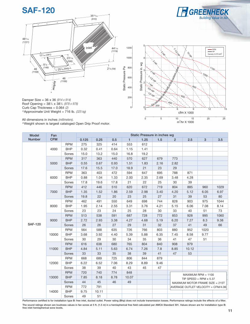
SAF-120
Do not s
elect
to th
e le
ft of
this
sys
tem
cur
ve
cfm
ModelNumber
FanCFM
Static Pressure in inches wg0.125 0.25 0.5 1 1.25 1.5 2 2.5 3 3.5
SAF-120
4000RPM 275 325 414 553 612BHP 0.32 0.41 0.64 1.15 1.41
Sones 15.0 13.2 15.0 16.8 19.2
5000RPM 317 363 440 570 627 679 773BHP 0.55 0.67 0.93 1.51 1.83 2.16 2.82
Sones 17.6 15.5 17.0 18.9 21 23 29
6000RPM 363 403 472 594 647 695 788 871BHP 0.88 1.04 1.33 2.00 2.35 2.69 3.48 4.28
Sones 17.8 19.6 17.8 21 22 25 30 39
7000RPM 412 446 510 620 672 719 804 885 960 1029BHP 1.35 1.52 1.86 2.59 2.98 3.40 4.20 5.12 6.05 6.97
Sones 19.8 22 20 23 25 27 31 39 53 80
8000RPM 462 491 550 649 698 744 828 903 975 1044BHP 1.95 2.14 2.55 3.31 3.76 4.21 5.15 6.06 7.08 8.14
Sones 23 23 24 25 28 30 33 40 51 73
9000RPM 513 538 591 687 728 772 853 928 995 1060BHP 2.72 2.93 3.38 4.27 4.68 5.19 6.20 7.27 8.3 9.38
Sones 26 26 27 29 31 32 37 41 49 66
10000RPM 564 588 635 726 766 803 880 952 1020BHP 3.68 3.92 4.40 5.39 5.88 6.35 7.45 8.58 9.77
Sones 30 29 30 34 35 36 41 47 51
11000RPM 616 638 680 765 804 840 908 979BHP 4.84 5.11 5.63 6.74 7.26 7.8 8.85 10.12
Sones 33 33 35 38 39 41 47 53
12000RPM 668 689 725 806 844 879BHP 6.22 6.52 7.06 8.29 8.89 9.46
Sones 38 39 40 43 45 47
13000RPM 720 740 774 848BHP 7.85 8.18 8.78 10.07
Sones 44 45 46 49
14000RPM 772 791BHP 9.75 10.11
Sones 49 51
11
Damper Size = 36 x 36 (914 x 914)Roof Opening = 381/2 x 381/2 (978 x 978)Curb Cap Thickness = 0.064 (2)^Approximate Unit Weight = 716 lb. (325 kg)
All dimensions in inches (millimeters). ^Weight shown is largest cataloged Open Drip Proof motor.
MAXIMUM RPM = 1100TIP SPEED = RPM x 5.37
MAXIMUM MOTOR FRAME SIZE = 215TAVERAGE OUTLET VELOCITY = CFM/4.06
Performance certified is for installation type B: free inlet, ducted outlet. Power rating (Bhp) does not include transmission losses. Performance ratings include the effects of a filter.
The sound ratings shown are loudness values in fan sones at 5 ft. (1.5 m) in a hemispherical free field calculated per AMCA Standard 301. Values shown are for installation type B: free inlet hemispherical sone levels.
P.O. Box 410 • Schofield, WI 54476-0410 • Phone (715) 359-6171 • greenheck.com00.F&V.1006 R5 7-2010
Copyright © 2010 Greenheck Fan Corp.
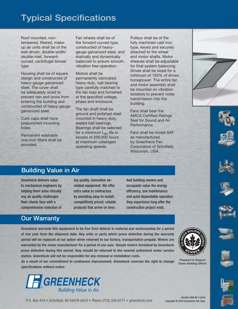
Typical Specifications
Roof mounted, non-tempered, filtered, make-up air units shall be of the belt-driven, double-width/double-inlet, forward-curved, centrifugal blower type.
Housing shall be of square design and constructed of heavy-gauge galvanized steel. The cover shall be adequately sized to prevent rain and snow from entering the building and constructed of heavy-gauge galvanized steel.
Curb caps shall have prepunched mounting holes.
Permanent washable one-inch filters shall be provided.
Fan wheels shall be of the forward-curved type, constructed of heavy- gauge galvanized steel, and statically and dynamically balanced to ensure smooth, vibration free operation.
Motors shall be permanently lubricated, heavy-duty, ball bearing type carefully matched to the fan load and furnished at the specified voltage, phase and enclosure.
The fan shaft shall be ground and polished steel mounted in heavy-duty, sealed ball bearings. Bearings shall be selected for a minimum L50 life in excess of 200,000 hours at maximum cataloged operating speeds.
Pulleys shall be of the fully machined cast iron type, keyed and securely attached to the wheel and motor shafts. Motor sheaves shall be adjustable for final system balancing. Drives shall be sized for a minimum of 150% of driven horsepower. The entire fan and motor assembly shall be mounted on vibration isolators to prevent noise transmission into the building.
Fans shall bear the AMCA Certified Ratings Seal for Sound and Air Performance.
Fans shall be model SAF as manufactured by Greenheck Fan Corporation of Schofield, Wisconsin, USA.
Building Value in Air
Greenheck warrants this equipment to be free from defects in material and workmanship for a period
of one year from the shipment date. Any units or parts which prove defective during the warranty
period will be replaced at our option when returned to our factory, transportation prepaid. Motors are
warranted by the motor manufacturer for a period of one year. Should motors furnished by Greenheck
prove defective during this period, they should be returned to the nearest authorized motor service
station. Greenheck will not be responsible for any removal or installation costs.
As a result of our commitment to continuous improvement, Greenheck reserves the right to change
specifications without notice.
Our Warranty
Prepared to SupportGreen Building Efforts
Greenheck delivers value to mechanical engineers by helping them solve virtually any air quality challenges their clients face with a comprehensive selection of
top quality, innovative air-related equipment. We offer extra value to contractors by providing easy-to-install, competitively priced, reliable products that arrive on time.
And building owners and occupants value the energy efficiency, low maintenance and quiet dependable operation they experience long after the construction project ends.