center for reliable computing - stanford university
TRANSCRIPT

Center forReliableComputing
TECHNICALREPORT
An Apparatus for Pseudo-Deterministic Testing
Shridhar K. Mukund, Edward J. McCluskey and T. R. N. Rao
94-12
(CSL TR # 94-642)
October 1994
Center for Reliable ComputingERL 460
Computer Systems LaboratoryDepartments of Electrical Engineering and Computer Science
Stanford UniversityStanford, California 943054055
Abstract:
Pseudo-random testing is popularly used, particularly in Built-In Self Test (BIST) applications. Toachieve a desired fault coverage, pseudo-random patterns are often supplemented with few deterministicpatterns. When positions of deterministic patterns in the pseudo-random sequence are known a priori,pseudo-random sub-sequences can be chosen such that they cover these deterministic patterns. We callthis method of test application, pseudo-deterministic testing. The theory of discrete logarithm has beenapplied to determine positions of bit-patterns in the pseudo-random sequence generated by a modularform or internal-XOR Linear Feedback Shift Register (LFSR) [5,7]. However, the scheme requires thatall the inputs of the combinational logic block (CLB), under test, come from the same LFSR source.This constraint in circuit configuration severely limits its application.
In this paper, we propose a practical and cost effective technique for pseudo-deterministic testing.For most part, the problem of circuit configuration has been simplified to one of scan path insertion, byemploying LFSR/SR (an arbitrary length shift register driven by a standard form or external-XORLFSR). To enable the usage of LFSR/SR as a pseudo-deterministic pattern source, we propose amethod to determine positions of bit-patterns, at arbitrarily chosen tap configurations, in the LFSR/SRsequence.
Funding:
This work was supported in part by the Innovative Science and Technology Office of the StrategicDefense Initiative Organization and administered through the Office of Naval Research under ContractNo. NOOO14-92-J- 1782, by the National Science Foundation under Grant No. MIP-9 107760, and byCirrus Logic Inc.
Copyright 0 1994 by the Center for Reliable Computing, Stanford University.All rights reserved, including the right to reproduce this report, or portions thereof, in any form.

An Apparatus for Pseudo-Deterministic Testing
Shridhar K. Mukund* and Edward J. McCluskey
CENTER FOR RELIABLE COMPUTING
Computer Systems Laboratory
Departments of Electrical Engineering and Computer Science
Stanford University
Stanford, CA 94305
T.R.N. Rao
CENTER FOR ADVANCED COMPUTER STUDIES
University of Southwestern Louisiana
Lafayette, LA 70504
CRC Report No. 94- 12
(CSL TR # 94-642)
October 1994
Abstract
Pseudo-random testing is popularly used, particularly in Built-In Self Test (BIST) appli-cations. To achieve a desired fault coverage, pseudo-random patterns are often supple-mented with few deterministic patterns. When positions of deterministic patterns in thepseudo-random sequence are known a priori, pseudo-random sub-sequences can bechosen such that they also cover these deterministic patterns. We call this method oftest application, pseudo-deterministic testing. The theory of discrete logarithm has beenapplied to determine positions of bit-patterns in the pseudo-random sequence generatedby a modular form or internal-XOR Linear Feedback Shift Register (LFSR) [Mukund 9 11,[Lempel94]. However, the scheme requires that all the inputs of the combinational logicblock (CLB), under test, come from the same LFSR source. This constraint in circuitconfiguration severely limits its application.
In this paper, we propose a practical and cost effective technique for pseudo-determinis-tic testing. For most part, the problem of circuit configuration has been simplified to oneof scan path insertion, by employing LFSR/SR (an arbitrary length shift register drivenby a standard form or external-XOR LFSR). To enable the usage of LFSR/SR as apseudo-deterministic pattern source, we propose a method to determine positions of bit-patterns, at arbitrarily chosen tap configurations, in the LFSR/SR sequence.
*. This author is with R&D, Cirrus Logic Inc., pursuing graduate study in Electrical Engineering through the HonorsCooperative Program at Stanford University.

Table of Contents1. Introduction . . . . . . . . . . . . . . . . . . . . . . . . . . . . . . . . . . . . . . . . . . 1
1.1 On Pseudo-Deterministic Testing 11.2 Modular Form LFSR - Generator of &ii”, ’ ‘. 1 1 : : : 1 .* .’ .* .*.‘.*.‘. . . ‘. 2
2. Motivation . . . . . . . . . . . . . . . . . . . . . . . . . . . . . . . . . . . . . . . . . . . . 3
3. Standard Form LFSR - The Dual . . . . . . . . . . . . . . . . . . . . . . . . . . . 3
4. LFSR/SR - The Apparatus . . . . . . . . . . . . . . . . . . . . . . . . . . . . . . . . 5
5. AnIllustration . . . . . . . . . . . . . . . . . . . . . . . . . . . . . . . . . . . . . . . . . 8
6. Conclusion . . . . . . . . . . . . . . . . . . . . . . . . . . . . . . . . . . . . . . . . . . 10
Acknowledgments . . . . . . . . . . . . . . . . . . . . . . . . . . . . . . . . . . . . . . . . . . . . . l lReferences . . . . . . . . . . . . . . . . . . . . . . . . . . . . . . . . . . . . . . . . . . . . . . . . . . . l l
List of FiguresFigure 1. Modular Form LFSR or SDC . . . . . . . . . . . . . . . . . . . . . . . . 2
Figure 2. A BIST Example . . . . . . . . . . . . . . . . . . . . . . . . . . . . . . . . . . 3
Figure 3. Standard Form LFSR . . . . . . . . . . . . . . . . . . . . . . . . . . . . . . 4
Figure 4. A I tap, N-stage LFSR/SR with n-stage driving LFSR . . . . . . 5
Figure 5. An Application of the Pseudo-Deterministic Test Apparatus . 8
Figure 6. SDC with feedback polynomial, x4 = 1 + x3 . . . . . . . . . . . . . 9
Figure 7. A sequence generated by a (10.4) LFSR/SR . . . . . . . . . . . . 10

1. IntroductionWith growing complexity of integrated circuits and systems, the cost of testing hasbecome ever more significant. BIST is increasingly being applied as an effective meansto reduce the cost of testing. The test complexity is cut down through systematic struc-tured approach and the test time is reduced through concurrency. BIST also gives usthe ability for testing parts in-circuit, and possibly on-line [McCluskey 851.
For built-in self testing, one must be able to generate and apply test patterns internally.Due to simplicity and compactness, LFSR is popularly used as the apparatus for gener-ating pseudo-random test patterns. Pseudo-random test patterns are effective when thecircuit is random-pattern testable. A typical circuit may however have some randompattern resistant (RPR) faults. As a result, it is often required to supplement random-patterns with few deterministically generated patterns. This situation may sometimesbe alleviated by using weighted random patterns or through logic changes to improverandom-pattern testability [Eichelberger 9 11. Several techniques that embed determin-istic patterns in pseudo-random sequence have been proposed [Dufaza 911, [Hellebrand921, [Vasudevan 931. These methods either have large area overhead or can embed onlya limited number of deterministic patterns.
1.1 On Pseudo-Deterministic Testing
An optimal choice of pseudo-random subsequences can be made, if positions of deter-ministic test vectors, say corresponding to RPR faults, is known a priori. Throughappropriate choice of seeds, the hardware apparatus for pseudo-random testing can bemade to additionally cover deterministic patterns. This method of pseudo-deterministictest application is especially well suited for BIST, where the test vectors have to be gener-ated internally.
When the LFSR has fewer stages, say less than 16, one can use the brute-force methodof running it through the maximal sequence and thereby determine positions of deter-ministic patterns. However, as the number of stages become larger, it becomes prohibi-tive to do so. The theory of discrete logarithms has been used to address this problem.
A related problem of interest is that of identifying RPR faults. Random-pattern resis-tance is a function of pseudo-random test length. The exponential dependency betweenpseudo-random test length and fault coverage, suggests that there is a point beyondwhich increasing the test length does not improve fault coverage significantly [McClus-key 881. For a given pseudo-random test length, an efficient method for identifying RPRfaults has been suggested in [waicukauski 851.
In order to find an optimal set of seeds, one must consider a reasonable size subset, ifnot all, of the test vectors for every RPR fault class. At least one of the test vectors foreach RPR fault class needs to be covered by the pseudo-deterministic sequence. Clearly,if a very short test length is chosen, the working set of patterns to consider can becomevery large. Therefore, pseudo-deterministic test is best thought of as an enhancementand not an alternative to pseudo-random test. This trade-off and related heuristics havebeen discussed in [Lempel 941.

1.2 Modular Form LFSR - Generator of GF(2n)The theory of discrete logarithm has been applied to determine positions of bit patternsin the sequence generated by a modular form LFSR [Mukund 911, [Lempel94]. Considerthe modular realization of a n-stage LFSR in Fig. 1, with the feedback polynomial
p(x) = cg+clx+ . . . +c,~lxn-l +xn .
We call this, the Shift Division Circuit (SDC).
Let p(x) be primitive and a be one of its roots in GF(Zn). Then we can identify the state:
P = [b() b, .** on-J
of the SDC with the field element:p = bo+bla+...+b,-,a”-’ *
Notice that every step of work performed by the device corresponds to multiplying thefield element /3 by the field element a. This means, starting from any non-zero state PO,the SDC generates all the other non-zero elements of GF(Zn) successively as:
In particular, in order to determine how many steps it will take for the SDC, startingfrom the state PO, to arrive at the state /3, we need only compute log,p - log,&.
CO Cl
Figure 1. Modular Form LFSR or SDC
The problem of computing the discrete logarithm, m = log,/3 , has received wide atten-tion in the area of Cryptography [Pohlig 781, [Coppersmith 841, [Odlyzko 84). If the valueof n is so chosen that ZR- 1 is a large prime or at least one of its prime factors is large,then it is very hard to extract logarithms in the field GF(2n). On the other hand, it ismuch easier to exponentiate. It is this disparity that led Diffe and Hellman [Diffe 761 topropose a cryptographic scheme based on exponentiation in finite field.
However, in the pseudo-deterministic test application, the value n can be chosen suchthat 2n- 1 is smooth (expressible as a product of relatively small primes). Fortunately,most values of n in the range of interest, say 16 < n < 100, are such that 2n-1 is smooth.Methods for computing discrete logarithms that are particularly suited for this applica-tion and the procedure for making choices of n have been proposed in [Mukund 911.

2. MotivationConsider the pseudo-random BIST situation of Fig. 2. The input registers can be config
Figure 2. A BIST Example
ured as independent LFSRs to test random pattern testable faults in CLBl and CLB2.However, for pseudo-deterministic testing, it is essential that all the inputs of every CLBcome from the same source. As a result, we need to configure the three registers intoone large LFSR, such that only a subset of the LFSR stages are connected to each CLB.The number of possible test patterns, for every RPR fault class, grows exponentially withthe difference in the number of LFSR stages and the number of CLB inputs. The prob-lem of identifying positions of deterministic test patterns is soon rendered impractical.In reality, the interplay between the inputs of CLBs is even more complex, especially innon-data path situations.
In order to satisfy the constraint that the inputs to every CLB must come from the samesource, we adopt LFSR/SR, a device proposed for pseudo-exhaustive testing [Bar-Alai831. LFSR/SR is simply a standard form LFSR driving an arbitrary length shift register(scan-chain). The inputs of CLBs are connected to the shift register at arbitrarily chosentap positions. Given certain tapping configuration, a method for selecting the feedbackpolynomial is discussed in [Barzilai 831. In practice, the number of stages in the drivingLFSR is one or two stages more than the number of inputs of the maximum input CLB .
Our intent is to find a method to determine positions of bit-patterns, at arbitrary tapconfigurations, in the sequence generated by the LFSR/SR.
3. Standard Form LFSR - The Dual 1
In preparation, we first develop a linear transformation that will help us identify posi-tions of bit-patterns in a standard form LFSR sequence.
*. Most combinational networks have more than one output. In many cases each of the outputs depend on only a subsetof the inputs. We can hence consider the input sets on which every output depends as the target, instead of CLBs[McCluskey 841. This can potentially make the driving LFSK smaller and hence further simplify the problem ofpseudo-deterministic test.

We call the autonomous time-sequential circuit of Fig. 3,
‘?- D < 4 De . . .
V V V
Figure 3. Standard Form LFSR
with the transition matrix:
T =
0 0 . . . 0 co1 0 . . . 0 Cl
0 1 . . . 0 c2
. . . . . . . . . . . . . . .0 0 . . . 1 C,-l
the standard form LFSR.
We also know that the transition matrix of an accompanying SDC with the same feed-back polynomial is the transpose:
TT =
0 1 0 . . . 010 0 1 . . . 0. . . . . . . . . . . . . . .o o o . . . 1co Cl c2 **- c,-1
If the feedback polynomial is primitive and we start from any non-zero state, then boththe circuits traverse through all the 2n - 1 distinct non-zero states. The position of a bit-pattern in the standard form LFSR sequence can be determined by the following theo-rem.
Theorem 1: There exists a one-to-one correspondence between,the state sets of a stan-dard form LFSR and a SDC with the same feedback polynomial, which is linear andrespects the succession of states in both the devices.
Proof: Considering the invertible matrix:
A =
it is easy to verify that:
Cl c2 cj . . . c,-l 1
c2 cg Cd . . . 1 0
. . . . . . . . . . . . . . . . .C n-l 1 0 . . . 0 0
1 0 o... 0 0
TA = ATT
(Equation 1)
Thus, if we define the linear mapping o by sending the state (3 of the standard form LFSRto the corresponding state:
o(P) = PA (Equation 2)
of the accompanying SDC, then it is evidently invertible and we see from:
o(PT) = PTA = PATT = o@)TT,
that the transition of states in both the devices is preserved. Q. E. D.
We see from this theorem that in order to determine the distance between the test vec-tors PO and p in the standard form LFSR, we need only compute log,a (p) - fog,0 (PO) .
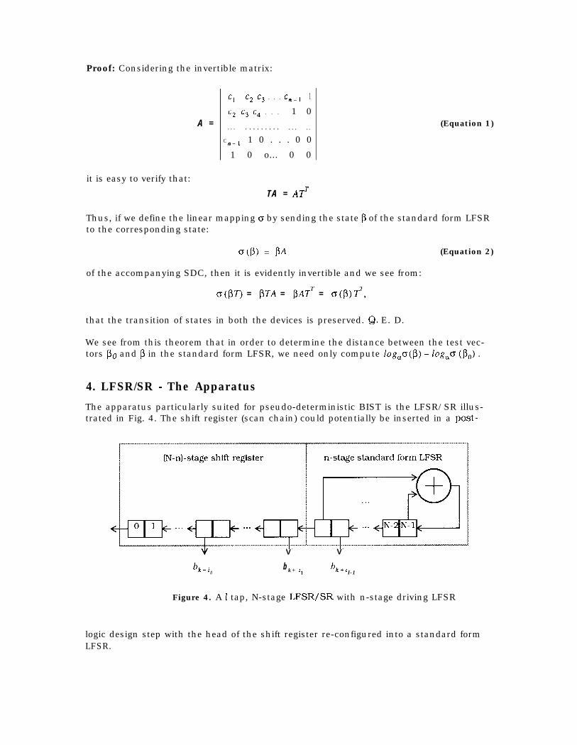
4. LFSR/SR - The ApparatusThe apparatus particularly suited for pseudo-deterministic BIST is the LFSR/SR illus-trated in Fig. 4. The shift register (scan chain) could potentially be inserted in a post-
bk+i0
Vb k + 1,
V
bk+iI-1
Figure 4. A 2 tap, N-stage LFSR/SR with n-stage driving LFSR
logic design step with the head of the shift register re-configured into a standard formLFSR.

As discussed in [Barzilai 831, one can generate test patterns of the form:
bk+i ... bk+i ,k”1 1I-1
by the help of an arbitrarily chosen tapping configuration:
T =[i, i, i, . . . i,-, ,Olii<N- 11
on a N-stage LFSR/SR, where the driving n-stage standard form LFSR has a primitivefeedback polynomial. A problem of interest is to make the choice of a primitive feedbackpolynomial such that all I-patterns can be generated at a set of s arbitrarily chosen tap-ping configurations*:
0, 1, 1, 1, s, 1,2 ,z , a*-, z *
To this end, a theorem is obtained in [Barzilai 831. Here we give a proof in a differentperspective that illustrates how the position of a test pattern 6k at the tapping confrgura-tion z can be determined in the LFSR/SR sequence.
Theorem 2: For any integer $, we divide x1’ by p(x) to obtain the remainder
r,, t-a = xfmod(p(X)) = CiI’ o+Ci,,l~+ ... +ci,,~-lxfl-l.
If the feedback polynomial p(x) is primitive, then the tapping configuration z generates allZ-patterns if and only if, the vectors:
y(f) = [q. c;,,~ . . . ci (Equation 3)I’
are linearly independent.
Proof: Suppose the LFSR starts working with the non-zero state:
P =[0 b, 6, . . . b,J
and we write:
Divide x1’ by p(x) to obtain:
XL1 = 4, (X>P (~1 + ri, (~1 deg trl (x> > < n *I I J
Then, since p(T) = 0, we see from:
pk+i, = pgTk+” = PkTLJ = Pkri CT) 7J
*. For the sake of clarity only one of the s tapping configurations is illustrated in Fig. 4.

that the signal b,, i , being the zeroth component of the vector pk+ i , can be computedas: I I
which means we have:
where:
(Equation 4)
Thus we see, if the columns of C are linearly dependent, then fixed non-trivial linearrelations can be found between the components of 6k. This means not all l-patterns canbe obtained from the tap configuration 2. If, on the contrary, the columns of C are lin-early independent, then since Pk can be any non-zero n-vector, every given Z-pattern canbe obtained by selecting a suitable k. Q. E. D.
In particular, if wecannot exceed n.
wish the tapping configuration to generate all the I-patterns then I
On the other hand, if L c n and the matrix C has rank I, then for any given l-vector 6,, thelinear system:
pc = 6, (Equation 5)
has 2(n - ‘I solutions for p, say V (6,) . Thus, if the driving LFSR starts with an initial statePO, then for every step:
2)= (N-n-k) + (fog,o(p) -fog,o(Bo))mod(2”-1), P E W,) (Equation 6)
of work, the configuration z will output the pattern 6,.

5. An IllustrationIn this section, we provide an example to illustrate the application of LFSR/SR inpseudo-deterministic testing. Consider the scenario shown in Fig. 5. The design has a
$) 2+0 2+2
/,.. *.A.. . . . .
*:. ‘5
. . .:.;::> . . . . . . . . . . . . . . . . . . . . .2 :: *.5.
;;.
2+6* . . . ..../... **,+.
d2) l+O 1+6 1+7
..:: ll..f -. . . . ;. . ,I‘ .:.- .:... n::. . .
TI
v v \I/1 1 1
CLB 1
Figure 5. An Application of the Pseudo-Deterministic Test Apparatus
set of registers, some of which are connected to the inputs of CLBl (gnd CLB2. The goalis to apply the deterministic pattern Sz(‘) = [I I I] to CLBl and 6, = 010 toCLB2.[ 1The registers are configured into a shift register. The order in which the registers areconnected is arbitrary. As a result, we have tap configurations 2(l) and x(2) connected toCLBl and CLB2 respectively. We can pick a primitive feedback polynomial for the driv-ing LFSR using the method suggested in [6], such that the columns of the C matricescorresponding to x(l) and T(~) are linearly independent. \nstead, $t us arbitrarily pick a4-stage LFSR with the primitive feedback polynomial: x = 1 + x , and test for the linearindependence of the columns of C matrices. From Eqn. 3, we have:
y(l) (0) = xOmod (p (x) ) = [ 1000] )y(l) (2) = x2mod (p (x) ) = [OOlO] ,y(l) (6) = x%od (p (x) ) = x4x2 = (1 +x3)x2 = x2+x5 = x2+ (1 +x3)x= x+x2+x4= 1 +x+x2+x3= [llll],
yc2) (0) = x’mod (p (x) ) = [ lOOO] ,YC2) (6) = [llll],
YC2) (7) = x6x = (1 +x+x2+x3)x = x+x2+x3+x4= 1 +x+x2= [lllO]
Therefore, from Eqn. 4,
C(l) = ~~~, and Cc2) = ~~~.
By inspection, the columns of Ct’) and Ct2) are linearly independent.
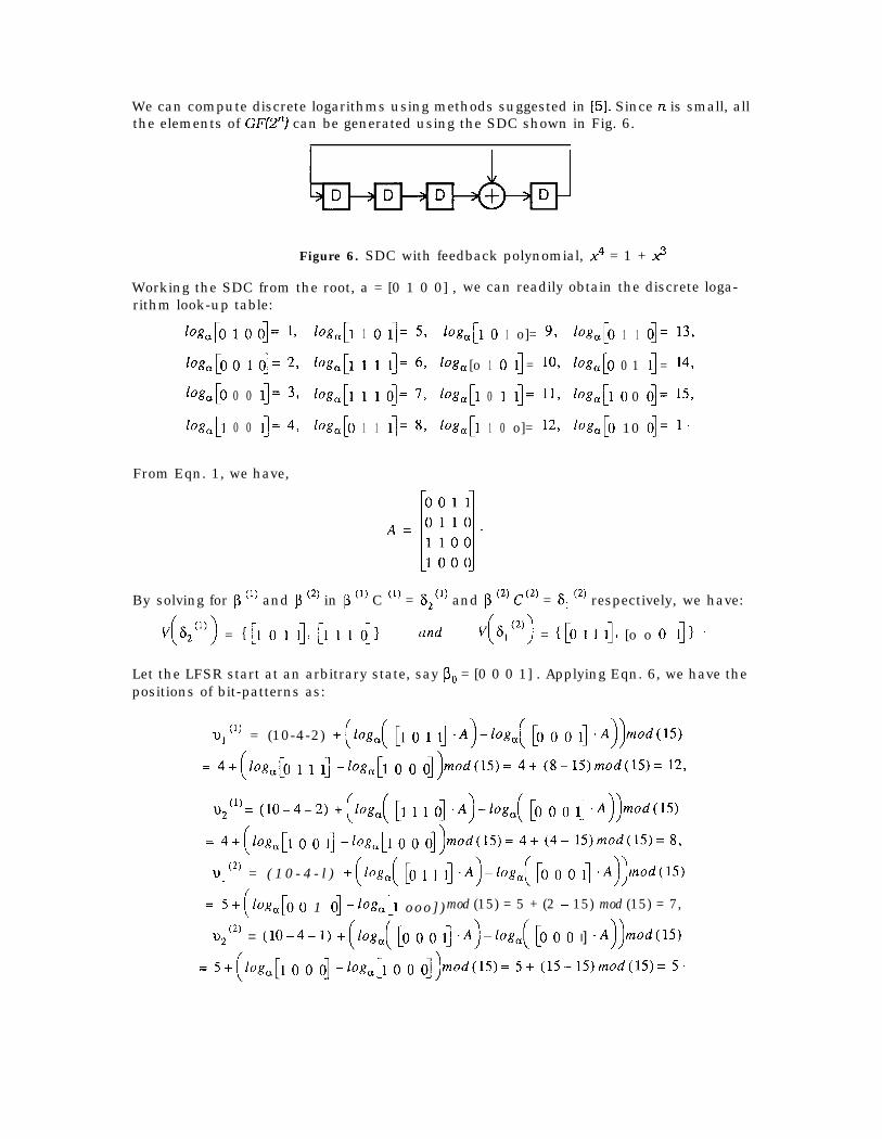
We can compute discrete logarithms using methods suggested in [5]. Since n is small, allthe elements of GFQn) can be generated using the SDC shown in Fig. 6.
Figure 6. SDC with feedback polynomial, x4 = 1 + 2
Working the SDC from the root, a = [0 1 0 0] , we can readily obtain the discrete loga-rithm look-up table:
log,[o 1 0 o]= 19 lo&J1 1 0 1]= 59 lOg,[l 0 1 o]= 93 @,[o 1 1 o]= 1%
log, [o 0 1 o] = 2, log, [l 1 1 1]= 69 1% [o 1 0 l] = 10, @,[o 0 1 l] = 14,
lw,[o 0 0 1]= 3, lo&J1 1 1 o]= 7, lo&J1 0 1 1]= 11, lo&J1 0 0 o]= 159
lo&J1 0 0 1]= 4, lo&Jo 1 1 1]= 87 @,[l 1 0 o]= 12, lo&[0 10 o]= 1.
From Eqn. 1, we have,
By solving for p (‘I and J3 (2) in p (‘I C (‘I = s211) and p 12) Cc2) = 6, (2) respectively, we have:
~(8~~~)) = I[1 o 1 I]~ [I 1 I 011 and v(Q2)) = $0 I I 1J [o o o 111 .Let the LFSR start at an arbitrary state, say PO = [0 0 0 1] . Applying Eqn. 6, we have thepositions of bit-patterns as:
2)1 (‘I = (10-4-2) +(log,( [I 0 1 11 .A)-log,( [o 0 0 11 .A))mod(l5)
= 4+(log,[O 1 1 I. -log& 0 0 o])mod(l5)= 4+ (8-15>mod(15)= 12,
2)2 (l)= (10-4-Z) +(log,( [I 1 1 o] ++og,( [o 0 0 1-j -A))mod(l5)
= 4+(Iog,,[1 0 0 11 -log& 0 0 o])mod(lS)= 4+ Cd-- 15)modU5)= 8,
Y (2) = ( 1 0 - 4 - l ) +(log,( [o 1 1 11 ++og,( [o 0 0 I] .A))mMlS)
= 5+(~og,[oo 1 o]-h,[l o o o ] ) mod (15) = 5 + (2 - 15) mod (15) = 7,
2)2 (2) = (10-4-1) +(fog,( [o 0 0 11 -A)-log,( [o 0 0 I] +())mod(lS)
= 5+(loga[1 0 0 01 -/og,[l 0 0 o])mod(l5)= 5+ (1545>mod(15)= 5.

(1)The bit pattern &2 = [ 1 1 1 1 at the tappin 9 configuration 2(l) is generated at the step 8and 12. The bit pattern s, c2) = 1 1o 1 o at z( ) is generated at the step 5 and 7.
Let us now verify the above by actually running the LFSR/SR as shown in Fig. 7.
REGO REGl REG2 REG3 REG4 REG5 REG6 REG7 REG8 REG9(1) (1) (1)
20 % z2
(2)ZO
(2)%
(2)z2
STEP01234567
9 1 1 1 1 0 1 0 1 1010 1 1 1 0 1 0 1 1 0 011 1 1 0 1 0 1 1 0 0 112 1 0 MI 0 IIlII 1 0 0 IDII 013 0 1 0 1 1 0 0 1 0 014 1 0 1 1 0 0 1 0 0 015 0 1 1 0 0 1 0 0 0 1
Figure 7. A sequence generated by a (10.4) LFSR/SR
Notice that if we seed the driving LFSR with the pattern [Ol 111, a sequence of length 7covers the bit patterns of interest. A minimum sequence length of 6 is required for thedriving LFSR to reach the farthest tap position, namely REG 1.
6. ConclusionFor pseudo-deterministic test (pseudo-random test that also covers a set of known deter-ministic patterns), one needs to identify positions of bit-patterns in pseudo-randomsequences. In this paper, a linear transformation [Eqn. 21 to relate the sequence gener-ated by a standard form (external-XOR) LFSR with that of an accompanying modularform (internal-XOR) LFSR has been presented. The positions of bit-patterns are thenidentified by computing discrete logarithms in the field generated by the accompanyingmodular form LFSR. A further transformation [Eqn. 51 to relate the sequence generatedby a standard form LFSR with the sequence generated at arbitrarily chosen tap positionsin a LFSR/SR (shift register driven by a standard form LFSR) is also presented. A for-mula [Eqn. 61 for identifying positions of bit-patterns in the sequence generated at thesetap positions has been provided.
Pseudo-deterministic test requires that all the inputs of every CLB (combinational logicblock) come from the same pattern source. In a typical BIST scenario, there is interplay
10

between the inputs of different CLBs. Hence, it is impractical to directly apply LFSR. Inthis paper, we have addressed this problem by proposing the use of LFSR/SR as the pat-tern source. An arbitrary length LFSR/SR can be created simply by scan chaining theregisters driving the CLBs, whose inputs interplay. This apparatus makes pseudo-deter-ministic testing practical and cost effective.
Acknowledgments
The authors gratefully acknowledge Kencheng Zeng and Pran Kurup for helpful com-ments and suggestions. This work was supported in part by the Innovative Science andTechnology Office of the Strategic Defense Initiative Organization and administeredthrough the Office of Naval Research under Contract No. NOOO14-92-J-1782, by theNational Science Foundation under Grant No. MIP-9107760, and by Cirrus Logic Inc.
References
[Barzilai 831 Barzilai, 2.. D. Coppersmith, and A. L. Rosenberg, “Exhaustive Generationof Bit Patterns with Applications to VLSI Self-Testing,” IEEE Trans. Cornput., Feb1983.
[Coppersmith 841 Coppersmith, D., “Fast Evaluation of Logarithms in Fields of Charac-teristic Two,” IEEE Trans. In-o. Theory, July 1984.
[Diffe 761 Diffe, W., and M. E. Hellman, “New Directions in Cryptography,” IEEE Trans.Info. Theory, 1976.
[Dufaza 911 Dufaza, C., and G. Cambon, “LFSR based Deterministic and Pseudo-Ran-dom Test Pattern Generator structures,” Proc. European Test Conference, 199 1.
[Eichelberger 9 l] Eichelberger, E. B., E. Lindbloom, J. A. Waicukauski and T. W. Will-iams, “Structured Logic Testing,” Prentice Hall, Englewood Cl@& New Jersey 1991.
[Hellebrand 921 Hellebrand, S., S. Tarnick and J. Rajski, “Generation of Vector PatternsThrough Reseeding of Multiple-Polynomial Linear Feedback Shift Registers,” Proc.ITC, 1992.
[Lempel94] Lempel, M., Sandeep K. Gupta, and Melvin A. Breuer, “Test Embedding withDiscrete Logarithms, * IEEE VLSI Test Symposium, 1994.
[McCluskey 88) McCluskey, E. J., Samy Makar, Samiha Mourad, and Kenneth D. Wag-ner, “Probability Models for Pseudorandom Test Sequences,” IEEE Trans. Computer-Aided Design, Jan. 1988.
[McCluskey 851 McCluskey, E. J., “Built-In Self-Test Techniques,” IEEE Design & Test,April, 1985.
[McCluskey 841 McCluskey, E. J., “Verification Testing-A Pseudoexhaustive Test Tech-nique,” IEEE Trans. Comput., June 1984.
[Mukund 911 Mukund, S. K., T.R.N. Rao, and Kencheng Zeng, “On Reducing Test Lengthin LFSR based Testing,” VLSI Design Symposium, Jan. 199 1.
[Odlyzko 841 Odlyzko, A. M., “Discrete Logarithms in Finite Fields and their Crypto-graphic Significance ,” Adv. in Cryptology (Proc. of Eurocrypt ‘84). Lecture Notes inComputer Science, Vol. 209, Springer-Verlag, New York, 1984.
11

[Pohlig 781 Pohlig, S. C., and Martin E. Hellman, “An Improved Algorithm for ComputingLogarithms over GF(p) and Its Cryptographic Significance,” IEEE Trans. Info. Theory,Jan. 1978.
[Vasudevan 93) Vasudevan, B., D.E. Ross, M. Gala and K.L. Watson, “LFSR Based Deter-ministic Hardware for At-Speed BIST,” Proc. VLSI Test Symp., 1993.
[Waicukauski 851 Waicukauski, J. A., Edward B. Eichelberger, Donato 0. Forlenza, EricLindbloom, and Thomas McCarthy, “Fault Simulation for Structured VLSI,” VLSISystems Design, Dec. 1985.
12