cellular network interface – 2 (cni2) - mercury … network interface – 2 (cni2) ......
TRANSCRIPT

Honeywell Process Solutions
Cellular Network Interface – 2 (CNI2)
Operating and Installation Guide
Issued: April 23, 2012
V 1.50 Honeywell

www.honeywell.com 1
Copyright © 2012, 2011 Honeywell | Mercury Instruments, Cincinnati, Ohio, USA.
www.honeywell.com 2
Contents REVISION HISTORY ................................................................................................................13
TRADEMARKS AND COPYRIGHTS .......................................................................................15
SYMBOLS AND ICONS. ..........................................................................................................16
IMPORTANT BATTERY INFORMATION .................................................................................19
CNI2 OVERVIEW .....................................................................................................................20
CNI2 FEATURES .....................................................................................................................20
CERTIFICATIONS ....................................................................................................................20
MECHANICAL ASSEMBLIES ..................................................................................................21
INSTRUMENT MOUNTING OPTIONS ................................................................................................... 21
WALL MOUNTING .................................................................................................................................. 21
METER INDEX BASE ............................................................................................................................. 22
VERTICAL PIPE MOUNTING ................................................................................................................. 25
ENCLOSURE SEALING ......................................................................................................................... 26
INTERNAL BATTERY POWER OPTIONS ............................................................................................. 26
INTERNAL CIRCUIT BOARDS ............................................................................................................... 29
CNI2 Board ......................................................................................................................................... 29
Serial Port Multiplexer Board .............................................................................................................. 30
Summary of Serial Data Connection Scenarios ................................................................................. 31
CNI2 INDEX BASE.................................................................................................................................. 32
OPTIONAL REMOTE PULSE TRANSMITTER ...................................................................................... 35
ANTENNA OPTIONS .............................................................................................................................. 36
TAMPER DETECT & CALL SWITCH OPTIONS .................................................................................... 39
ELECTRICAL ASSEMBLIES ...................................................................................................40
CIRCUIT BOARD CONNECTORS & JUMPERS ................................................................................... 40
Cellular Radio Module ......................................................................................................................... 41
SIM Card Socket ................................................................................................................................. 41
Reset Jumper JP4............................................................................................................................... 41
Power Connectors J1 & J2 ................................................................................................................. 41
Terminal Block TB2 ............................................................................................................................. 42
Terminal Block TB4 ............................................................................................................................. 42
JP3 & JP6 Jumper Settings ................................................................................................................ 42
Connector J4 ....................................................................................................................................... 43
Connector J7, J9, J11 and J12 ........................................................................................................... 43
Terminal Block TB1 ............................................................................................................................. 44
RS-232 MULTIPLEXER BOARD ............................................................................................................ 45
UNCORRECTED PULSE OUTPUT BOARD .......................................................................................... 47
SIGNAL INPUTS & OUTPUTS ............................................................................................................... 48
Alarm / Pulse Inputs ............................................................................................................................ 48
Pulse Counting Inputs ......................................................................................................................... 51
Outputs ................................................................................................................................................ 51
POWER SUPPLY OPTIONS .................................................................................................................. 52
Extending Battery Life ......................................................................................................................... 52
Low Battery Detection ......................................................................................................................... 53
AC MAINS POWER CONFIGURATION ................................................................................................. 53
SOLAR POWER CONFIGURATION ...................................................................................................... 54
SERIAL PORT CONNECTIONS - TB2 ................................................................................................... 55
SIM SOCKET CONNECTION ................................................................................................................. 56
PROGRAMMING INFORMATION ............................................................................................58
STARTING THE MP32® CONFIGURATION PROGRAM ....................................................................... 59
www.honeywell.com 3
CONFIGURING THE PROGRAMMING PORT ...................................................................................... 60
STARTING THE CNI2 PROGRAMMING APPLICATION....................................................................... 61
MAIN SCREEN ....................................................................................................................................... 62
Saving and Retrieving Configurations................................................................................................. 62
Remote Unit ID (RUID) ...................................................................................................................... 62
Primary Destination ............................................................................................................................. 62
Originate Calls ..................................................................................................................................... 63
Allow Connection Requests ................................................................................................................ 63
Respond to Voice Calls / Respond to SMS ........................................................................................ 63
Time Interval Size ............................................................................................................................... 63
Firmware Version ................................................................................................................................ 64
Compare Device Configuration to Template ....................................................................................... 64
INPUT / OUTPUT CONFIGURATION .................................................................................................... 65
Alarm Input Parameters ...................................................................................................................... 65
“Special Purpose” Input Parameters ................................................................................................... 67
Pulse-Counting Input Parameters ....................................................................................................... 69
Output Parameters .............................................................................................................................. 72
Output Under Host Control.............................................................................................................. 72
Output Follows Input ....................................................................................................................... 72
“Special Purpose” Output ................................................................................................................ 74
OPTIONS SCREEN ................................................................................................................................ 75
Applications Selection ......................................................................................................................... 75
Metretek SIP ................................................................................................................................... 76
Metretek SIP via InvisiConnect ....................................................................................................... 76
Metretek InvisiConnect .................................................................................................................... 76
Mercury MINI-MAX or Mercury Pulse Accumulator ........................................................................ 76
Metretek SMS Modem .................................................................................................................... 76
Transparent Modem ........................................................................................................................ 77
Allow Transparent Mode ..................................................................................................................... 77
When Answering if No Port Select……............................................................................................... 78
Low Battery Alarm ............................................................................................................................... 80
Queue Size ......................................................................................................................................... 81
Queue Full Alarm ................................................................................................................................ 81
Sample Rates ...................................................................................................................................... 81
SERIAL PORT CONFIGURATION SCREEN ......................................................................................... 82
Port Select ID ...................................................................................................................................... 82
Port Enable ......................................................................................................................................... 82
Max BPS. Data Bits, Parity, Stop Bits ................................................................................................. 82
Flow Control ........................................................................................................................................ 83
Hardware Handshaking ................................................................................................................... 83
Software Handshaking .................................................................................................................... 84
No (None) Handshaking .................................................................................................................. 84
RS-485 Half Duplex ........................................................................................................................ 84
Delay before Sending Packets ............................................................................................................ 84
Listening Port ...................................................................................................................................... 85
Always Send CONNECT Message ..................................................................................................... 85
Always “RING” Port ............................................................................................................................. 85
Use Non-verbose Result Codes ......................................................................................................... 86
Enable Blocking .................................................................................................................................. 86
Use Alternate CONNECT Message .................................................................................................... 86
Connect on DTR High ......................................................................................................................... 86
Disconnect on DTR Low ..................................................................................................................... 87
CELLULAR SETTINGS SCREEN........................................................................................................... 88
“SIP” Versus “MIP” .............................................................................................................................. 88
“Dynamic” Versus “Static” IP Addresses............................................................................................. 88
CDMA Service (Aeris, Verizon, Sprint) ............................................................................................... 89
www.honeywell.com 4
CDMA Packet (Internet) Service ..................................................................................................... 89
CDMA Circuit Switched Data (CSD) Service .................................................................................. 89
Over-the-Air-Activation (OTAA) ...................................................................................................... 90
OTAA Programming Number .......................................................................................................... 91
Packet Service Connection Command ........................................................................................... 92
Session Timeout ............................................................................................................................. 92
Ping Interval .................................................................................................................................... 92
Source Port Starting / Ending Numbers .......................................................................................... 92
PAP User Name and Password ...................................................................................................... 92
Maximum Packet Size ..................................................................................................................... 93
Auxiliary Radio Type ....................................................................................................................... 93
GSM Service (AT&T, T-Mobile, Rogers)............................................................................................. 94
GSM Packet (Internet) Service ....................................................................................................... 94
GSM Circuit Switched Data (CSD) Service .................................................................................... 95
Installation of the SIM Card ............................................................................................................. 96
GPRS Access Point Name.............................................................................................................. 97
Packet Service Connection Command ........................................................................................... 97
Session Timeout ............................................................................................................................. 97
Ping Interval .................................................................................................................................... 97
Source Port Starting / Ending Numbers .......................................................................................... 97
PAP User Name and Password ...................................................................................................... 98
PIN Number..................................................................................................................................... 98
Maximum Packet Size ..................................................................................................................... 98
Auxiliary Radio Type ....................................................................................................................... 99
iDENService (Nextel, Harmony) ......................................................................................................... 99
HSPA Service ................................................................................................................................... 100
CALL SCHEDULING SCREEN ............................................................................................................. 101
Call Retry Strategy ............................................................................................................................ 101
Primary Call Retry Count .................................................................................................................. 101
Primary Call Retry Interval ................................................................................................................ 102
Secondary Call Retry Interval ........................................................................................................... 102
Try Alternate Destination .................................................................................................................. 102
Enable Repetitive Call Schedule ....................................................................................................... 102
Special Retry Strategy for Unique InvisiConnect Applications ......................................................... 103
SERVER MODE .................................................................................................................................... 105
“Servers” and “Clients” ...................................................................................................................... 105
Server Mode Requirements .............................................................................................................. 105
Server Mode Security........................................................................................................................ 105
Server Mode Start / End Options ...................................................................................................... 106
Server Mode LED Indicators ............................................................................................................. 106
Configuring the CNI2 for Server Mode.............................................................................................. 107
Allow Connection Requests .......................................................................................................... 107
Modem (CNI2) Listening Port Number .......................................................................................... 108
Friends List .................................................................................................................................... 108
Hardware-Triggered Server Mode ................................................................................................ 109
ATD Command-Triggered Server Mode ....................................................................................... 111
Scheduled Server Mode ................................................................................................................ 112
How Does the CNI2 Know What Day It Is? ...................................................................................... 112
Daylight Savings Time (DST) adjustment ..................................................................................... 113
Time Zone Adjustment .................................................................................................................. 114
Early Termination of a Server Session ............................................................................................. 115
Interruption of a Server Session ....................................................................................................... 116
Connections to a Specific Serial Port ................................................................................................ 117
PROGRAMMING THE CNI2 ................................................................................................................. 118
Loading a Configuration with the Programming Cable ..................................................................... 118
OVER-THE-AIR (OTA) PROGRAMMING............................................................................................. 120
www.honeywell.com 5
What is Over-the-Air Programming? ................................................................................................. 120
Over-the-Air Configuration Changes Using DC-2009® ..................................................................... 120
Over-the-Air “Firmware” Changes Using DC-2009® ......................................................................... 122
Over-the-Air Configuration Changes Using InvisiConnect® .............................................................. 123
Over-the-Air Firmware Changes Using InvisiConnect® .................................................................... 124
MERCURY INSTRUMENTS EMULATION ............................................................................. 126
WHAT ARE ITEM CODES? .................................................................................................................. 126
DIFFERENCES BETWEEN METRETEK AND MERCURY DEVICES ................................................ 126
WRITE-PROTECTED ITEM CODES .................................................................................................... 127
ITEM CODES PROTECTED BY ITEM-139 .......................................................................................... 128
MULTIPLE ACCESS ITEM CODES ..................................................................................................... 129
SERVER MODE (“CALL-OUT”) ITEM CODES .................................................................................... 130
Item-487 (Call-in Keep Alive Time) ................................................................................................... 131
Item-488 (Call-out Repeat Interval) ................................................................................................... 131
Item-490 (Call-out Start Time) .......................................................................................................... 131
Item-485 (Call-out Stop Time) ........................................................................................................... 131
Item-489 (Call-out Keep Alive Time) ................................................................................................. 131
How Changes to Call-Out Items Affect MP32’s Server Mode Settings ............................................ 132
How Changes to MP32’s Server Mode Setting Affect the Call-Out Item Codes .............................. 134
MEASUREMENT (PULSE-COUNTING) ITEM CODES ....................................................................... 135
What are “Volume Unit” Item Codes? ............................................................................................... 137
What are “Pulse Value” Item Codes? ............................................................................................... 138
What is the “Energy Unit” Item Code? .............................................................................................. 139
What are “Scaling Factor” Item Codes?............................................................................................ 139
What is the “Energy Value” Item Code? ........................................................................................... 139
How are Pulse Counts Converted and Corrected? ........................................................................... 140
THE AUDIT TRAIL SIZE ....................................................................................................................... 142
THE “T&A” AND “T&A2” EVENT RECORDS ....................................................................................... 143
“FIRST-TIME” ITEM CODE DEFAULT VALUES .................................................................................. 145
RESET ITEM CODE DEFAULT VALUES............................................................................................. 146
PROGRAMMING THE ITEM CODES................................................................................................... 148
Local Programming ........................................................................................................................... 148
Remote Programming ....................................................................................................................... 148
TRANSPARENT MODEM OPERATION .............................................................................................. 149
POWER PRESERVATION MODE .......................................................................................... 151
TRIGGERING POWER PRESERVATION MODE WITH THE LOW-BATTERY ALARM SET POINT 153
TRIGGERING POWER PRESERVATION MODE WITH A HARDWARE INPUT ................................ 154
Configuring Metretek SIP or InvisiConnect Devices ......................................................................... 156
Configuring Mercury PA or Mini-Max Devices .................................................................................. 157
LED STATUS INDICATORS .................................................................................................. 158
CALL PROGRESS AND STATUS (CLIENT MODE) ............................................................................ 158
ERROR CODES .................................................................................................................................... 159
LEDS AFTER OVER-THE-AIR REPROGRAMMING ........................................................................... 164
TECHNICAL INFORMATION ................................................................................................. 165
“SAMPLE RATE” EXPLAINED ............................................................................................................. 165
“DEBOUNCE” EXPLAINED .................................................................................................................. 166
What is Switch “Bounce”? ................................................................................................................. 166
What is “Debouncing”? ..................................................................................................................... 166
FORM-C OPERATION .......................................................................................................................... 168
USING THE OUTPUTS ........................................................................................................................ 169
OUTPUT SIGNAL POLARITIES ....................................................................................................... 169
www.honeywell.com 6
OUTPUT-FOLLOWS-INPUT ............................................................................................................ 170
OUTPUT-FOLLOWS-INPUT ACCURACY ERRORS ................................................................... 170
OUTPUT-FOLLOWS-INPUT DELAY ERRORS ........................................................................... 170
CONVERTING AN OUTPUT TO DRY CONTACT ........................................................................... 171
AT MODEM EMULATION MODE ......................................................................................................... 175
ATV (response type) Command ....................................................................................................... 176
ATE (echo) Command ...................................................................................................................... 176
ATH (hangup) Command .................................................................................................................. 176
ATZ (reset) Command ...................................................................................................................... 176
ATA (answer) Command .................................................................................................................. 176
ATD (dial) Command ........................................................................................................................ 176
+++ (escape) Command ................................................................................................................... 177
AT Command Chaining ..................................................................................................................... 177
AT+ICLK? (time and date) Command .............................................................................................. 177
AT+TOTALS? Command .................................................................................................................. 178
AT+PORTx Command ...................................................................................................................... 179
Response to AT Commands while in SLEEP Mode ......................................................................... 180
DC-2009 DATA COLLECTION SOFTWARE SETUP FOR METRETEK “SIP” MODE .......... 181
INTRODUCTION ................................................................................................................................... 181
SETTING UP THE SIP SERVER FOR PACKET (INTERNET) CONNECTIONS ................................ 181
SETTING UP DC-2009 FOR CSD CONNECTIONS ............................................................................ 183
SETTING UP A CALL SCHEDULE....................................................................................................... 185
DEFINING THE CNI2 – MANUAL MODE ........................................................................................... 188
CONFIGURING THE CNI2 ................................................................................................................... 191
CONFIGURING THE CNI2’S PULSE-COUNTING INPUTS ................................................................ 192
CONFIGURING THE CNI2’S CALL INFORMATION ............................................................................ 194
CONFIGURING THE CNI2’S ALARMS ................................................................................................ 195
Customer Alarm-1 ............................................................................................................................. 196
Customer Alarm-2 ............................................................................................................................. 196
Magnetic or ”CALL” Switch Alarm ..................................................................................................... 196
TAMPER Detect Alarm ..................................................................................................................... 197
AC-OFF Alarm .................................................................................................................................. 197
AC-ON Alarm .................................................................................................................................... 197
Unit Reset Alarm ............................................................................................................................... 197
Call Retry Alarm ................................................................................................................................ 197
Queue Full Alarm .............................................................................................................................. 197
Clock Resync Alarm .......................................................................................................................... 197
Remote Daily Volume Low Input-1,2,3,4 .......................................................................................... 198
Remote Daily Volume High Input-1,2,3,4.......................................................................................... 198
Remote TTI Consumption Low Input-1,2,3,4 .................................................................................... 198
Remote TTI Consumption High Input-1,2,3,4 ................................................................................... 198
Low Battery Alarm ............................................................................................................................. 198
DEFINING THE CNI2 – AUTOMATIC MODE .................................................................................... 199
STARTING DC-2009 ............................................................................................................................. 199
OBTAINING THE CNI2’S CELLULAR PHONE NUMBER.................................................................... 199
OBTAINING THE CNI2’S HARDWARE STATUS AND CELLULAR INFORMATION .......................... 200
TROUBLESHOOTING GUIDE ............................................................................................... 205
HARDWARE ALARM-SENSING .......................................................................................................... 205
PULSE-COUNTING .............................................................................................................................. 206
POWER SOURCE ................................................................................................................................ 207
NETWORK LOW-SIGNAL PROBLEMS ............................................................................................... 208
NETWORK CONNECTION PROBLEMS (CLIENT MODE) ................................................................. 209
NETWORK CONNECTION PROBLEMS (SERVER MODE) ............................................................... 210
www.honeywell.com 7
SERIAL PORT ....................................................................................................................................... 212
MAINTENANCE ..................................................................................................................... 215
BATTERY REPLACEMENT .................................................................................................................. 215
CLEANING AND CHEMICAL COMPATIBILITY LIST .......................................................................... 215
MAINTENANCE CHECKLIST ............................................................................................................... 215
ESD HANDLING PRECAUTIONS .......................................................................................... 217
CONTROL DRAWINGS - HAZARDOUS AREA ..................................................................... 218
HAZARDOUS AREA CLASSIFICATION (NORTH AMERICAN CLASS I, DIVISION 2) ..................... 218
SPECIFICATIONS .................................................................................................................. 222
CERTIFICATIONS ................................................................................................................................ 222
CELLULAR CARRIER CERTIFICATIONS ........................................................................................... 222
MECHANICAL ....................................................................................................................................... 223
Operational Temperature range ........................................................................................................ 223
Environmental Ratings ...................................................................................................................... 223
Enclosure Mounting .......................................................................................................................... 223
Mounting Direction ............................................................................................................................ 223
Humidity Range ................................................................................................................................. 223
Cable Glands .................................................................................................................................... 223
Weight of CNI2 with Wall Mount Option: (w/o batteries).................................................................. 223
Weight of CNI2 with Meter Mount Option: (w/o batteries) ............................................................... 223
Battery Pack Shipping Weight .......................................................................................................... 224
J9, J12 Connector Type .................................................................................................................... 224
J7, J11 Connector Type .................................................................................................................... 225
TB4 Connector Type ......................................................................................................................... 225
ELECTRICAL - POWER ....................................................................................................................... 226
Battery Voltage: (without load applied) ............................................................................................ 226
Approved Battery Pack Assemblies .................................................................................................. 226
Battery Life ........................................................................................................................................ 226
Current Requirements during Transmission ..................................................................................... 226
Sleep current (data logger mode, no communications option boards) ............................................. 226
Boost Capacitor ................................................................................................................................. 227
Low-Voltage Detector........................................................................................................................ 227
Power Input #3 (TB1) Connector Type ............................................................................................. 227
Power Input #1 & #2 (J1 and J2) Connector Type ............................................................................ 227
ELECTRICAL - GENERAL .................................................................................................................... 228
Pulse Count Retention Memory ........................................................................................................ 228
Flash Program Memory .................................................................................................................... 228
Static RAM Memory .......................................................................................................................... 228
Clocks ............................................................................................................................................... 228
Logic Supply Voltage ........................................................................................................................ 228
Auxiliary Supply Voltage ................................................................................................................... 228
ELECTRICAL – DIGITAL OUTPUTS .................................................................................................... 229
Number of outputs............................................................................................................................. 229
Output Configuration ......................................................................................................................... 229
Source resistance ............................................................................................................................. 229
Operating Modes ............................................................................................................................... 229
Recommended Output Cable ........................................................................................................... 229
ELECTRICAL – DIGITAL INPUTS ........................................................................................................ 230
Number of inputs ............................................................................................................................... 230
Input Configuration ............................................................................................................................ 230
Input rate (sampling mode) ............................................................................................................... 230
Minimum input pulse width (sampling mode) .................................................................................... 230
www.honeywell.com 8
Sample rate (sampling mode) ........................................................................................................... 230
Debounce Count (sampling mode) ................................................................................................... 230
Input rate (edge-detection mode) ...................................................................................................... 230
Minimum pulse width (edge-detection mode) ................................................................................... 230
Wetting current per input ................................................................................................................... 230
Wetting voltage ................................................................................................................................. 230
Input resistance ................................................................................................................................. 230
Recommended Input Cable .............................................................................................................. 230
ELECTRICAL – SERIAL PORT (TB2) .................................................................................................. 231
Number of input lines ........................................................................................................................ 231
Input levels ........................................................................................................................................ 231
Number of output lines ...................................................................................................................... 231
Output levels ..................................................................................................................................... 231
Bit rate ............................................................................................................................................... 231
TB2 Connector Type ......................................................................................................................... 231
FUNCTIONAL ....................................................................................................................................... 232
Modes of Operation........................................................................................................................... 232
Cellular Network Communications Options (varies with model) ....................................................... 232
Paging Mechanisms .......................................................................................................................... 232
Status Indicators ............................................................................................................................... 232
Firmware and Configuration Programming ....................................................................................... 232
CELLULAR RADIO AND ANTENNA INFORMATION .......................................................................... 233
GSM24 .............................................................................................................................................. 233
CDMA24 ............................................................................................................................................ 233
HSPA24 ............................................................................................................................................ 233
iDen270 ............................................................................................................................................. 233
Receive Frequencies ........................................................................................................................ 233
Transmit Frequencies ....................................................................................................................... 233
Antenna Connector ........................................................................................................................... 233
Antenna (internal quad-band) (GSM24, CDMA24) ........................................................................... 233
Antenna (internal quad-band) (iDEN270) ......................................................................................... 233
ASCII CHART ........................................................................................................................................ 234
www.honeywell.com 9
Figures
Wall Mounting Tabs and Dimensions ........................................................................................21
Wall Mount Hangers Assembly Sequence ................................................................................22
CNI2 with Universal Mounting Bracket (UMB) ...........................................................................23
Bottom View of the Universal Mounting Bracket (UMB) .............................................................24
Universal Mounting Bracket (UMB) Hole Pattern .......................................................................24
Pipe Mounting using Collar .......................................................................................................25
Pipe Mounting using U-Bolts .....................................................................................................25
Enclosure Sealing Options ........................................................................................................26
Lithium Battery Pack Mounting ..................................................................................................26
Alkaline Battery Pack Mounting .................................................................................................27
Disposable Alkaline Battery Pack ..............................................................................................28
CNI2 Board Orientation .............................................................................................................29
CNI2 Board and Multiplexer Board ............................................................................................30
CNI2 with single RS-232 connection to an external instrument. ................................................31
This is the default configuration. ................................................................................................31
CNI2 with multiplexer board to support two serial data links. .....................................................31
Index Base with Magnetic Switches ..........................................................................................32
Pulse Output Board ...................................................................................................................33
Internal View of the Index Base .................................................................................................33
Rotation Gears within the Index Base .......................................................................................34
Remote Pulse Transmitter ........................................................................................................35
Location of the Internal Antenna ...............................................................................................36
Antenna Connection to GSM, CDMA and HSPA Radio Modules ..............................................37
U.FL Antenna Connector for iDEN Radio Modules ....................................................................37
Antenna Connection Location for iDEN Radio Modules ............................................................37
Bottom View with External RF Connector ..................................................................................38
Location of the TAMPER and CALL Switches ...........................................................................39
CNI2 Circuit Board Layout.........................................................................................................40
J1 and J2 Power Connectors ....................................................................................................41
Configuration Jumpers ..............................................................................................................42
Jumper Block JP6 Settings .......................................................................................................43
Jumper Block JP3 Settings .......................................................................................................43
Capacitor Connection to TB1 (prewired) ...................................................................................44
The arrow points to the black reserve capacitor ........................................................................44
Serial RS-232 Multiplexer Board ...............................................................................................45
Wiring to the Serial RS-232 Multiplexer Board ..........................................................................46
Uncorrected Pulse Output Board ..............................................................................................47
Alarm / Pulse Input Terminal Block TB4 ....................................................................................48
Alarm / Pulse Input Connectors J9, J10, J11 and J12 ...............................................................49
CNI2 Power Connections ..........................................................................................................52
AC Power Adapter ....................................................................................................................53
External Power Tie-In Block ......................................................................................................54
Typical Solar Power System .....................................................................................................54
Serial Port Terminal Block TB2 .................................................................................................55
Typical SIM Card ......................................................................................................................56
Installation of the SIM Card .......................................................................................................57
Serial and USB Programming Cables .......................................................................................58
www.honeywell.com 10
MP32® Login Screen .................................................................................................................59
MP32® Device Selection Screen ...............................................................................................59
Programming Port Configuration Screen ...................................................................................60
CNI2 Main Configuration Screen ...............................................................................................61
Standard Alarm Descriptions .....................................................................................................65
Configuration of an Alarm Input .................................................................................................66
Configuration of a “Special Purpose” Input ................................................................................68
Configuration of a Pulse Counting Input ....................................................................................69
Examples of Using the Scaling Factor .......................................................................................70
Changing the Polarity of the “Output-Follows-Input” Feature .....................................................73
Configuration of a “Special Purpose” Output .............................................................................74
Options Screen .........................................................................................................................75
“Applications” Selection Menu ...................................................................................................75
“Route To” Port Selection in Transparent Mode ........................................................................79
Serial Port Configuration Screen ...............................................................................................82
Hardware Flow Control .............................................................................................................84
DTR Detection Jumper ..............................................................................................................87
CDMA Cellular Configuration Screen ........................................................................................91
Installation of the SIM Card .......................................................................................................96
GSM Cellular Configuration Screen ..........................................................................................96
Call Scheduling Screen ........................................................................................................... 101
Server Mode Enable Checkbox ............................................................................................... 107
Server Mode Screen ............................................................................................................... 108
Using a Hardware Input Line to Start and Stop a Server Session ........................................... 109
Server Mode Duration Setting ................................................................................................. 110
Scheduled Server Mode Screen ............................................................................................. 112
CNI2 Server Time Adjustment ................................................................................................. 114
Early Termination of a Server Session .................................................................................... 115
Serial Port Listening Port Number ........................................................................................... 117
Attaching the Programming Cable........................................................................................... 118
DC-2009 OTA Device Selection Screen .................................................................................. 121
InvisiConnect® OTA Configuration Screen .............................................................................. 123
InvisiConnect® OTA Firmware Screen ..................................................................................... 125
Write-protected Item Codes .................................................................................................... 127
Multiple Access Item Codes .................................................................................................... 130
Server Mode (“Call-Out”) Item Codes ...................................................................................... 130
Server Mode Results of Item Code Changes .......................................................................... 133
Example Scheduled Server Mode ........................................................................................... 134
Measurement-Related Item Codes .......................................................................................... 136
Volume Unit Item Codes and Multipliers.................................................................................. 137
Pulse Value Item Codes and Multipliers. ................................................................................. 138
Energy Unit Item Code and Multiplier. ..................................................................................... 139
Raw Pulse Count Item Code Settings ..................................................................................... 140
Correction and Conversion Equations ..................................................................................... 141
Selecting the Audit Trail Size in MP32 .................................................................................... 142
“First-Time” Item Code Default Values .................................................................................... 145
Reset Item Code Default Values ............................................................................................. 146
Reset Item Code Default Values (continued) .......................................................................... 147
Serial Connection to the CNI2 ................................................................................................. 148
Enabling Transparent Modem Operation ................................................................................. 149
www.honeywell.com 11
Power Preservation Mode Jumper .......................................................................................... 152
Low-Battery Alarm Point ......................................................................................................... 153
Hardware Trigger Example #1 ................................................................................................ 155
Hardware Trigger Example #2 ................................................................................................ 155
Hardware-Triggered “Power Preservation Mode” Settings for Metretek Devices ..................... 156
Hardware-Triggered “Power Preservation Mode” Settings for Mercury Devices ...................... 157
Example of Error Code “35” Display ........................................................................................ 159
LED Error Codes 11 thru 19 .................................................................................................... 160
LED Error Codes 21 thru 39 .................................................................................................... 161
LED Error Codes 41 thru 49 .................................................................................................... 162
LED Error Codes 51 thru 59 .................................................................................................... 163
LED Error Codes 61 thru 79 .................................................................................................... 164
Example of Timed Sampling ................................................................................................... 165
Example of Switch Bounce ..................................................................................................... 166
Example of Debouncing Process ............................................................................................ 167
Typical Form-A and Form-C (KYZ) Connections ..................................................................... 168
Example of Detection of a Form-C Fault ................................................................................. 168
Polarities of the Output Lines .................................................................................................. 169
Accuracy Errors Using the “Output-Follows-Input” Feature ..................................................... 170
Delay Errors Using “Output-Follows-Input” Feature ................................................................. 170
Converting the CNI2’s “J7” Output to Dry Contact ................................................................... 171
Changing the Polarity of the “Output-Follows-Input” Feature ................................................... 172
Converting the CNI2’s “J9” or “J12” Output to Dry Contact ...................................................... 173
Converting the CNI2’s “J11” Output to Dry Contact ................................................................. 174
Typical CNI2 “AT” Responses ................................................................................................. 175
Received Data (RXD) Detection Jumper ................................................................................. 180
Starting the DC-2009 System Configuration ............................................................................ 181
Changing the Data Collection Configuration ............................................................................ 182
Configuring the SIP Server ..................................................................................................... 183
Configuring DC-2009 for CSD Connections ............................................................................ 184
Configuring a Call Schedule .................................................................................................... 185
Defining a Call Profile Name ................................................................................................... 186
Defining a Call Profile.............................................................................................................. 187
Starting the CNI2 Configuration Process ................................................................................. 188
Remote Unit Selection Screen ................................................................................................ 189
Device Type Selection Screen ................................................................................................ 189
Add Remote Unit Screen ........................................................................................................ 190
Remote Unit Configuration General Information Screen .......................................................... 191
Device Configuration Screen ................................................................................................... 192
Data Input Configuration Screen ............................................................................................. 193
Call Information Screen ........................................................................................................... 194
Hardware Alarm Configuration Screen .................................................................................... 195
Viewing the Cellular and Hardware Status .............................................................................. 200
Cellular and Hardware Status Screen ..................................................................................... 201
Starting the Call Diagnostic Dump Utility ................................................................................. 202
Using the Call Diagnostic Dump Utility .................................................................................... 203
Status and Cellular Information on the Call Dump Screen ....................................................... 203
Cellular Information Fields ...................................................................................................... 204
Hardware Alarm-Sensing Troubleshooting Guide ................................................................... 205
Pulse-Counting Troubleshooting Guide ................................................................................... 206
www.honeywell.com 12
Power Source Troubleshooting Guide ..................................................................................... 207
Network Low-Signal Troubleshooting Guide ........................................................................... 208
Network Connection (Client Mode) Troubleshooting Guide ..................................................... 209
Network Connection (Server Mode) Troubleshooting Guide.................................................... 210
Network Connection (Server Mode) Troubleshooting Guide (continued) ................................. 211
Serial Port Troubleshooting Guide .......................................................................................... 212
Serial Port Troubleshooting Guide (continued) ........................................................................ 213
J9 and J12 Connectors ........................................................................................................... 224
J7 and J11 Connectors ........................................................................................................... 225
TB4 Plug ................................................................................................................................. 225
Power Input Connector Polarities ............................................................................................ 227
TB2 Plug (7-Position Plug Not Shown) .................................................................................... 231
ASCII Conversion Chart .......................................................................................................... 234

www.honeywell.com 13
Version 1.00 April 23, 2010 - Initial release of draft document.
Version 1.01 May 3, 2010
- Redefined section breaks. - Redefined some text styles to allow automatic inclusion into the table of contents. - Added figure titles to all illustrations and added a list of figures after the table of contents. - Moved battery regulations statements and warnings to the beginning of the document. - Added an auto-date field to the cover sheet. - Refined and added to the section that deals with programming the unit.
Version 1.02 August, 2010 (currently in red for easy identification)
- Clarified the difference between Simple Internet Protocol and Mobile Internet Protocol and how to select which one to use.
- Elaborated how low battery conditions are detected and reported. - Clarified which configurations can use the “Try Alternate Destination” feature. - Added text and figures for RS-485 Full-Duplex and Half-Duplex operation. - Added additional error codes to the Error Code tables.
Version 1.03 February 1, 2011
- Honeywell update. - Change text to consistent color.
Version 1.10 February 21, 2011
- Added a trademark reference for AutoSol®. - Added a new chapter called “Mercury Instruments Emulation”. - Added notes about over-the-air configuration and firmware changes from InvisiConnect. - Added or changed certain items in the Specifications section. -
Version 1.20 April 4, 2011 - Added a new chapter called “Trouble Shooting Guide”. - Added notes about the use of the Scaling Factor for pulse-counting inputs.
Version 1.30 June 6, 2011
- Added support for Item-139 when the CNI2 is configured for Mercury protocol. - Added technical information about HSPA (“3G”) network support.
Version 1.40 March 20, 2012
- Added new FCC ID numbers that were issued when Telit purchased Motorola’s M2M radio products. Also added the FCC ID number for the h24 HSPA radio.
- Added information about addressing specific serial ports while in Server Mode. - Added a new chapter called “Power Preservation Mode”. - Modified the table listing the JP6 jumper settings. Location 15/16 is now used to enable
or disable “Power Preservation Mode”. - Added information about the low-battery alarm point as it relates to “Power Preservation
Mode”.
REVISION HISTORY

www.honeywell.com 14
- Added information about several new “AT” commands: AT+TOTALS? and AT+PORTx. - Changed the “Mercury Instruments Emulation” section to more clearly define what the
“T&A” and “T&A2” alarm records mean. - Added new information about the “Output-Follows-Input” function for the I/O lines. We
now allow the user to define whether the output should be the true or inverted version of the input.
- Added information about the reporting of the radio’s MEID or IMEI serial number when calling in as a Metretek SIP or InvisiConnect device.
- Removed text and illustrations that refer to the RS-485 option board. - Updated illustrations to show the revised location for the tamper detect switch. - Added new illustration that shows the location of the reserve capacitor component. - Added additional information about iDEN radios.
Version 1.50 April 23, 2012
- Documented a special retry strategy for unique InvisiConnect applications that was introduced in V1.6 of the CNI2 firmware.
- Documented some enhancements to Server mode that were introduced in V1.6 of the CNI2 firmware.

www.honeywell.com 15
“Windows” refers to Microsoft Windows 2000, XP, Vista and Windows-7 that are either registered trademarks or trademarks of Microsoft Corporation in the United States and/or other countries. “MV90®” is either a registered trademark or trademark of Itron Corporation. “DC-2009®” “MP32®”, “InvisiConnect®” and “Masterlink®” are either registered trademarks or trademarks of Honeywell International. “AutoSol®” is either a registered trademark or trademark of Automation Solutions and refers to their AutoSol Enterprise Server (AES). Other brands and product names are trademarks or registered trademarks of their respective holders.
Metretek, Inc. was a business that produced data logging and telemetry products, and enterprise software, between 1977 and 2008. Metretek was acquired by Mercury Instruments, LLC in 2008 and the Metretek name was retired. Mercury Instruments was acquired by Honeywell in 2010. The Metretek and Mercury names appear in this document as a reference to legacy products and protocols, which are still in use today.
For additional information please contact a Product Support Specialist or visit our website.
Honeywell | Mercury Instruments 3940 Virginia Ave. • Cincinnati, Ohio 45227 USA
Phone 513-272-1111 • Fax 513-272-0211 www.honeywell.com
www.mercuryinstruments.com
TRADEMARKS AND COPYRIGHTS
www.honeywell.com 16
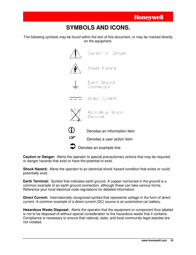
The following symbols may be found within the text of this document, or may be marked directly
on the equipment.
Denotes an information item
Denotes a user action item
Denotes an example line
Caution or Danger: Alerts the operator to special precautionary actions that may be required, or danger hazards that exist or have the potential to exist. Shock Hazard: Alerts the operator to an electrical shock hazard condition that exists or could potentially exist. Earth Terminal: Symbol that indicates earth ground. A copper rod buried in the ground is a common example of an earth ground connection, although these can take various forms. Reference your local electrical code regulations for detailed information. Direct Current: Internationally recognized symbol that represents voltage in the form of direct current. A common example of a direct current (DC) source is an automotive car battery. Hazardous Waste Disposal: Alerts the operator that the equipment or component thus labeled is not to be disposed of without special consideration to the hazardous waste that it contains. Compliance is necessary to ensure that national, state, and local community legal statutes are not violated.
SYMBOLS AND ICONS.
www.honeywell.com 17
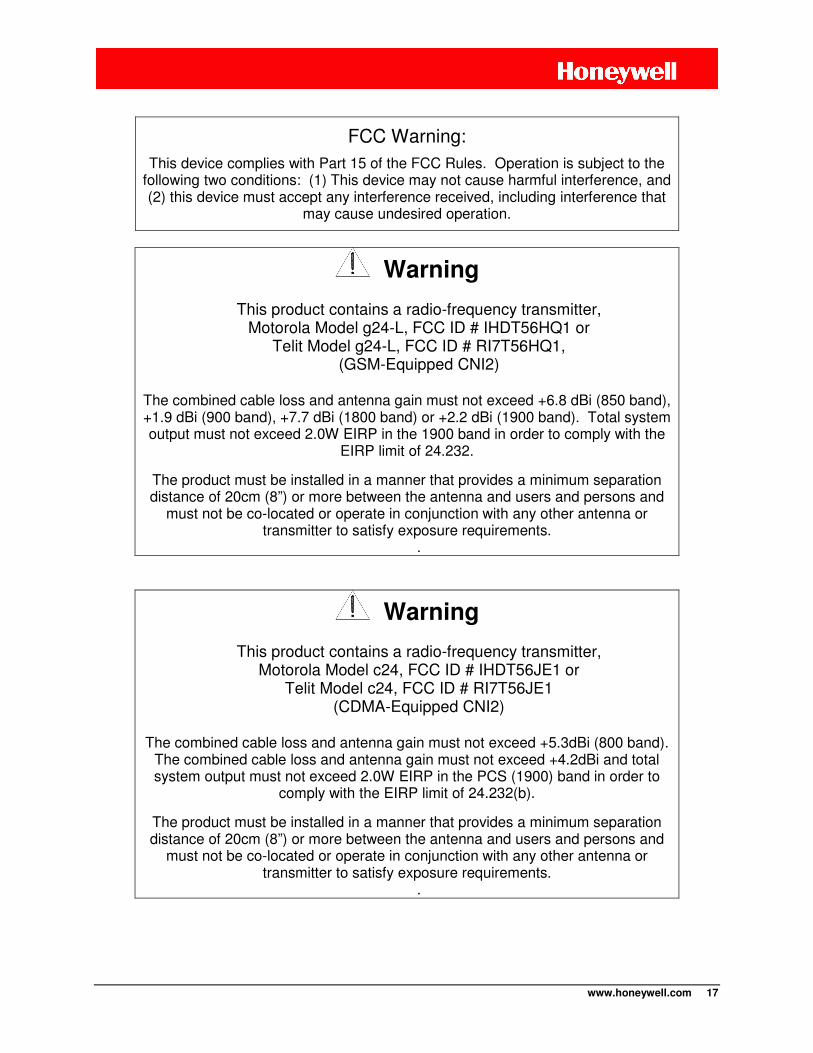
FCC Warning:
This device complies with Part 15 of the FCC Rules. Operation is subject to the following two conditions: (1) This device may not cause harmful interference, and (2) this device must accept any interference received, including interference that
may cause undesired operation.
Warning
This product contains a radio-frequency transmitter, Motorola Model g24-L, FCC ID # IHDT56HQ1 or
Telit Model g24-L, FCC ID # RI7T56HQ1, (GSM-Equipped CNI2)
The combined cable loss and antenna gain must not exceed +6.8 dBi (850 band), +1.9 dBi (900 band), +7.7 dBi (1800 band) or +2.2 dBi (1900 band). Total system output must not exceed 2.0W EIRP in the 1900 band in order to comply with the
EIRP limit of 24.232.
The product must be installed in a manner that provides a minimum separation distance of 20cm (8”) or more between the antenna and users and persons and
must not be co-located or operate in conjunction with any other antenna or transmitter to satisfy exposure requirements.
.
Warning
This product contains a radio-frequency transmitter, Motorola Model c24, FCC ID # IHDT56JE1 or
Telit Model c24, FCC ID # RI7T56JE1 (CDMA-Equipped CNI2)
The combined cable loss and antenna gain must not exceed +5.3dBi (800 band).
The combined cable loss and antenna gain must not exceed +4.2dBi and total system output must not exceed 2.0W EIRP in the PCS (1900) band in order to
comply with the EIRP limit of 24.232(b).
The product must be installed in a manner that provides a minimum separation distance of 20cm (8”) or more between the antenna and users and persons and
must not be co-located or operate in conjunction with any other antenna or transmitter to satisfy exposure requirements.
.
www.honeywell.com 18
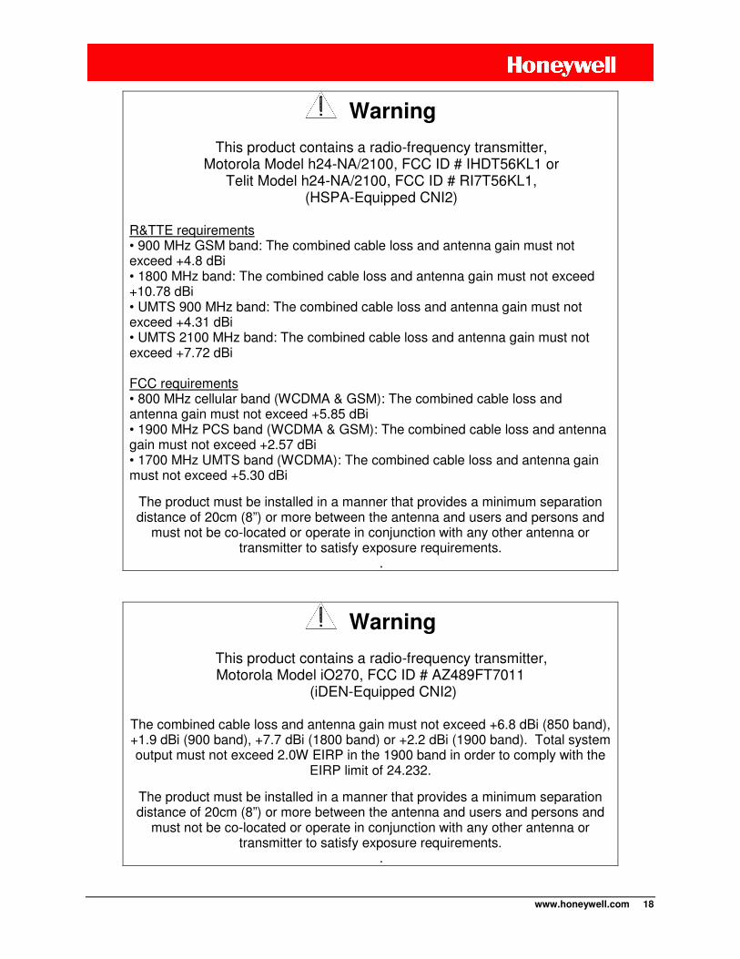
Warning
This product contains a radio-frequency transmitter, Motorola Model h24-NA/2100, FCC ID # IHDT56KL1 or
Telit Model h24-NA/2100, FCC ID # RI7T56KL1, (HSPA-Equipped CNI2)
R&TTE requirements • 900 MHz GSM band: The combined cable loss and antenna gain must not exceed +4.8 dBi • 1800 MHz band: The combined cable loss and antenna gain must not exceed +10.78 dBi • UMTS 900 MHz band: The combined cable loss and antenna gain must not exceed +4.31 dBi • UMTS 2100 MHz band: The combined cable loss and antenna gain must not exceed +7.72 dBi FCC requirements • 800 MHz cellular band (WCDMA & GSM): The combined cable loss and antenna gain must not exceed +5.85 dBi • 1900 MHz PCS band (WCDMA & GSM): The combined cable loss and antenna gain must not exceed +2.57 dBi • 1700 MHz UMTS band (WCDMA): The combined cable loss and antenna gain must not exceed +5.30 dBi
The product must be installed in a manner that provides a minimum separation distance of 20cm (8”) or more between the antenna and users and persons and
must not be co-located or operate in conjunction with any other antenna or transmitter to satisfy exposure requirements.
.
Warning
This product contains a radio-frequency transmitter, Motorola Model iO270, FCC ID # AZ489FT7011
(iDEN-Equipped CNI2)
The combined cable loss and antenna gain must not exceed +6.8 dBi (850 band), +1.9 dBi (900 band), +7.7 dBi (1800 band) or +2.2 dBi (1900 band). Total system output must not exceed 2.0W EIRP in the 1900 band in order to comply with the
EIRP limit of 24.232.
The product must be installed in a manner that provides a minimum separation distance of 20cm (8”) or more between the antenna and users and persons and
must not be co-located or operate in conjunction with any other antenna or transmitter to satisfy exposure requirements.
.
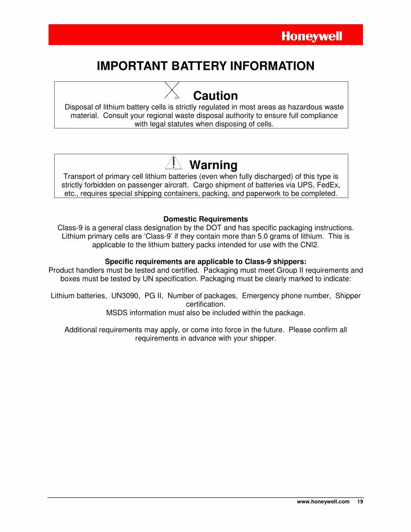
www.honeywell.com 19
Caution Disposal of lithium battery cells is strictly regulated in most areas as hazardous waste
material. Consult your regional waste disposal authority to ensure full compliance with legal statutes when disposing of cells.
Warning Transport of primary cell lithium batteries (even when fully discharged) of this type is strictly forbidden on passenger aircraft. Cargo shipment of batteries via UPS, FedEx, etc., requires special shipping containers, packing, and paperwork to be completed.
Domestic Requirements Class-9 is a general class designation by the DOT and has specific packaging instructions.
Lithium primary cells are ‘Class-9’ if they contain more than 5.0 grams of lithium. This is applicable to the lithium battery packs intended for use with the CNI2.
Specific requirements are applicable to Class-9 shippers:
Product handlers must be tested and certified. Packaging must meet Group II requirements and boxes must be tested by UN specification. Packaging must be clearly marked to indicate:
Lithium batteries, UN3090, PG II, Number of packages, Emergency phone number, Shipper
certification. MSDS information must also be included within the package.
Additional requirements may apply, or come into force in the future. Please confirm all
requirements in advance with your shipper.
IMPORTANT BATTERY INFORMATION
www.honeywell.com 20
The Honeywell CNI2 is a pulse accumulator (data logger) and serial data communications product with an integral cellular radio transceiver. Pulse signal inputs (dry contact) and alarm inputs can be supplied from an external electronic corrector or other measurement device. An index base option with both a mechanical index display and pulse switch output is available. Serial data communications with a corrector or similar instrument are also possible using an RS-232 connection or optional dual connections. A variety of power options are also available. These include alkaline battery, lithium battery, or an external source such as solar or an ac-to-dc converter.
• Numerous pulse counting inputs and alarm trigger inputs are supported. • Optional meter index base enables direct mounting onto a gas meter. • Several mounting options provide flexibility to mount to a wall, pipe, meter, etc. • Cellular radio service options include conventional GSM, CDMA, iDEN and HSPA. • The internal antenna feature conceals the nature of the wireless device. Where signal
strength is a concern, external antenna options are also supported. • Various power options are available, including alkaline battery, lithium battery, or
connections for external sourced power. External power can be either AC mains or solar.
• Power Preservation Mode extends battery backup life during loss of primary power. • The enclosure is field proven durable and UV resistant against weather effects. • Over-the-air firmware update capability allows for new feature enhancements as they
become available. • Over-the-air configuration update capability allows for changes in the operating
environment once the device is put into service (except in Canada).
• CSA Hazardous area certification, Class I, Div-2, Group-D • PTCRB cellular network approvals (for GSM-based units) • FCC Part 15(B), 22, 24 • Measurement Canada Metrology • Approved for use with AT&T, T-Mobile and Rogers GPRS (GSM) networks • Approved for use on Verizon, Sprint and Aeris 1XRTT (CDMA) networks. • iDEN units operate on the Nextel or Harmony networks.
CNI2 OVERVIEW
CNI2 FEATURES
CERTIFICATIONS

www.honeywell.com 21
INSTRUMENT MOUNTING OPTIONS
A number of options are available for convenient installation of the CNI2 product. These should be clearly specified at the time of order to ensure that the field technician has everything he or she needs to install the product.
WALL MOUNTING
Where a flat wall surface is available, such as on the side of a building or shed, stainless steel “hangers” can be utilized. Illustrated below is the rear view of a CNI2, along with associated mounting dimensions.
Wall Mounting Tabs and Dimensions
MECHANICAL ASSEMBLIES
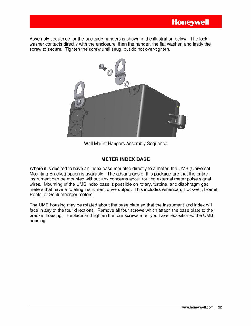
www.honeywell.com 22
Assembly sequence for the backside hangers is shown in the illustration below. The lock-washer contacts directly with the enclosure, then the hanger, the flat washer, and lastly the screw to secure. Tighten the screw until snug, but do not over-tighten.
Wall Mount Hangers Assembly Sequence
METER INDEX BASE
Where it is desired to have an index base mounted directly to a meter, the UMB (Universal Mounting Bracket) option is available. The advantages of this package are that the entire instrument can be mounted without any concerns about routing external meter pulse signal wires. Mounting of the UMB index base is possible on rotary, turbine, and diaphragm gas meters that have a rotating instrument drive output. This includes American, Rockwell, Romet, Roots, or Schlumberger meters. The UMB housing may be rotated about the base plate so that the instrument and index will face in any of the four directions. Remove all four screws which attach the base plate to the bracket housing. Replace and tighten the four screws after you have repositioned the UMB housing.

www.honeywell.com 23
CNI2 with Universal Mounting Bracket (UMB)

www.honeywell.com 24
The bottom side of the UMB meter index is seen below, along with the ‘wriggler’ mechanism.
Bottom View of the Universal Mounting Bracket (UMB)
The following illustration provides reference dimensions for the base plate.
Universal Mounting Bracket (UMB) Hole Pattern
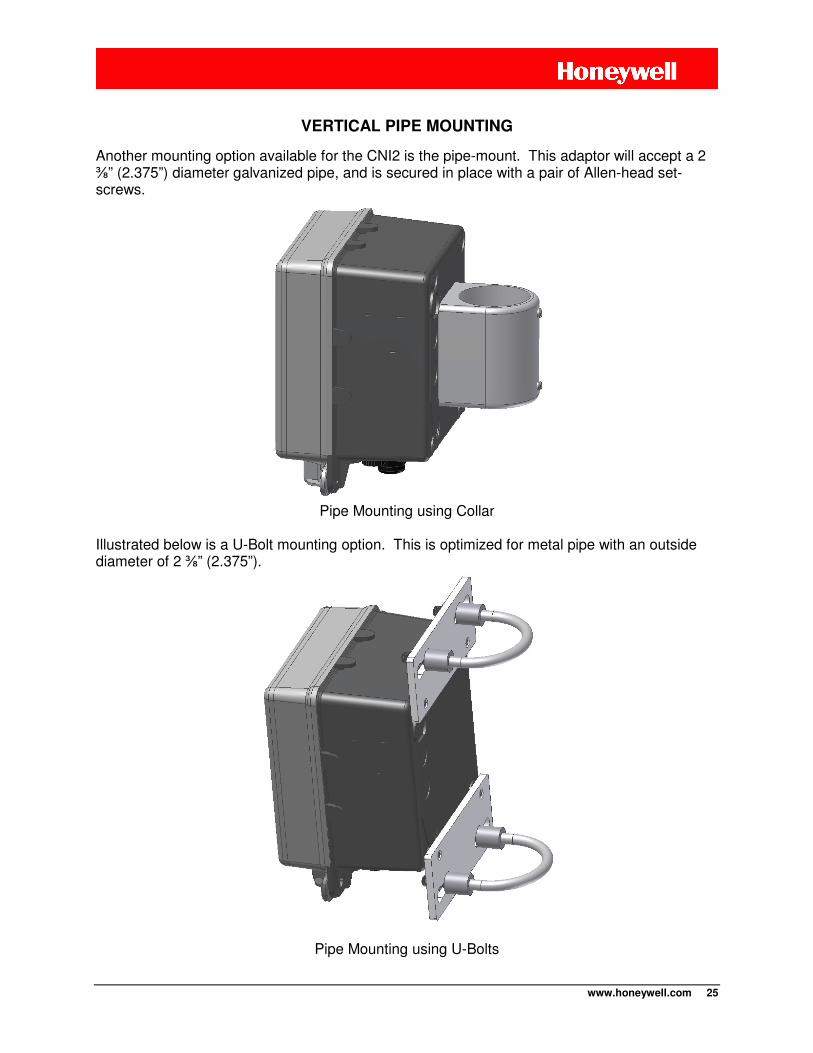
www.honeywell.com 25
VERTICAL PIPE MOUNTING
Another mounting option available for the CNI2 is the pipe-mount. This adaptor will accept a 2 ⅜” (2.375”) diameter galvanized pipe, and is secured in place with a pair of Allen-head set-screws.
Pipe Mounting using Collar
Illustrated below is a U-Bolt mounting option. This is optimized for metal pipe with an outside diameter of 2 ⅜” (2.375”).
Pipe Mounting using U-Bolts

www.honeywell.com 26
ENCLOSURE SEALING
Sealing of the enclosure is readily accomplished using either a conventional lock through the larger hole or a security wire seal through the smaller hole.
Enclosure Sealing Options
INTERNAL BATTERY POWER OPTIONS
Several battery configurations are available to best serve the particular applications. Shown below is the dual-cell lithium power pack. This pack inserts onto the enclosure door with the right-side of the metal plate tilted inwards first, and then snapping secure on the left side. Removal is the opposite, and it is a simple matter of pressing outwards against the plastic lever.
Lithium Battery Pack Mounting

www.honeywell.com 27
A larger quad-cell lithium pack is also available for double the capacity of the dual cell type. Refer to the specifications section at the end of this manual for a comprehensive listing of battery pack options their part numbers. Alkaline battery packs are available in either disposable form, or with a molded plastic housing that permits direct replacement of individual cells. The illustration below shows the plastic housing model mounted onto the enclosure door. Although the molded battery housing has a higher initial cost, it offers the advantage of replacement cell availability from numerous local suppliers.
NOTE When replacing alkaline batteries, only use new fresh cells from the same supplier and
having equivalent part numbers.
Alkaline Battery Pack Mounting
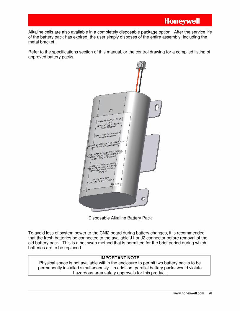
www.honeywell.com 28
Alkaline cells are also available in a completely disposable package option. After the service life of the battery pack has expired, the user simply disposes of the entire assembly, including the metal bracket. Refer to the specifications section of this manual, or the control drawing for a compiled listing of approved battery packs.
Disposable Alkaline Battery Pack
To avoid loss of system power to the CNI2 board during battery changes, it is recommended that the fresh batteries be connected to the available J1 or J2 connector before removal of the old battery pack. This is a hot swap method that is permitted for the brief period during which batteries are to be replaced.
IMPORTANT NOTE Physical space is not available within the enclosure to permit two battery packs to be permanently installed simultaneously. In addition, parallel battery packs would violate
hazardous area safety approvals for this product.
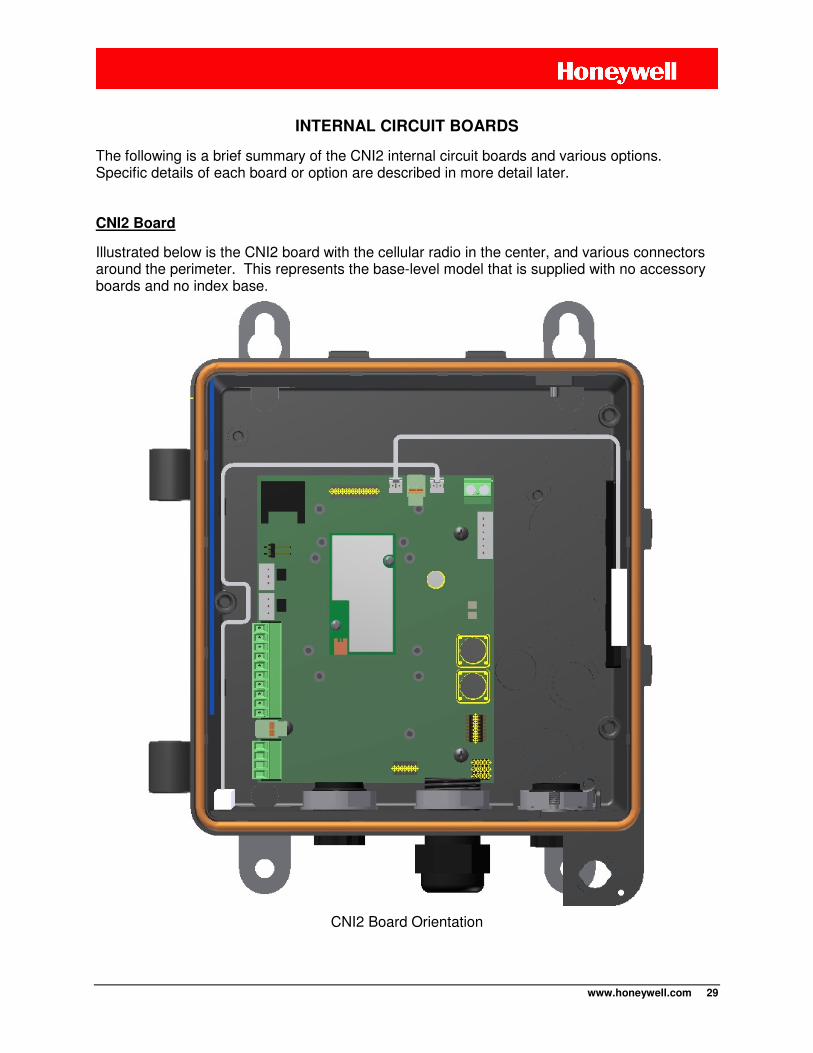
www.honeywell.com 29
INTERNAL CIRCUIT BOARDS
The following is a brief summary of the CNI2 internal circuit boards and various options. Specific details of each board or option are described in more detail later.
CNI2 Board
Illustrated below is the CNI2 board with the cellular radio in the center, and various connectors around the perimeter. This represents the base-level model that is supplied with no accessory boards and no index base.
CNI2 Board Orientation
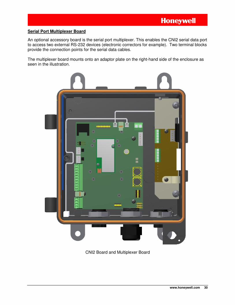
www.honeywell.com 30
Serial Port Multiplexer Board
An optional accessory board is the serial port multiplexer. This enables the CNI2 serial data port to access two external RS-232 devices (electronic correctors for example). Two terminal blocks provide the connection points for the serial data cables. The multiplexer board mounts onto an adaptor plate on the right-hand side of the enclosure as seen in the illustration.
CNI2 Board and Multiplexer Board
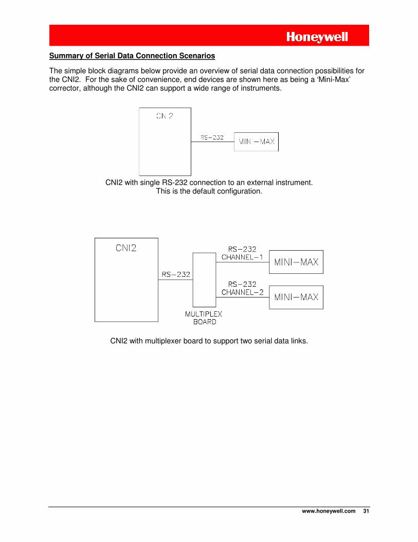
www.honeywell.com 31
Summary of Serial Data Connection Scenarios
The simple block diagrams below provide an overview of serial data connection possibilities for the CNI2. For the sake of convenience, end devices are shown here as being a ‘Mini-Max’ corrector, although the CNI2 can support a wide range of instruments.
CNI2 with single RS-232 connection to an external instrument.
This is the default configuration.
CNI2 with multiplexer board to support two serial data links.
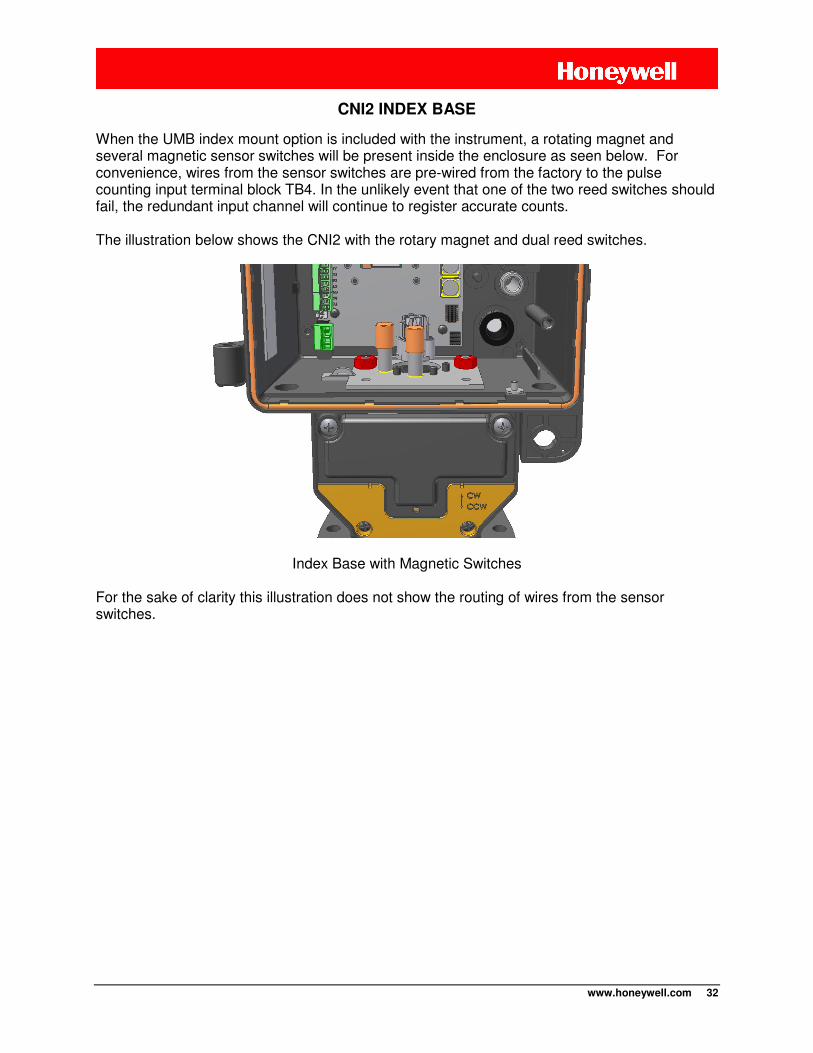
www.honeywell.com 32
CNI2 INDEX BASE
When the UMB index mount option is included with the instrument, a rotating magnet and several magnetic sensor switches will be present inside the enclosure as seen below. For convenience, wires from the sensor switches are pre-wired from the factory to the pulse counting input terminal block TB4. In the unlikely event that one of the two reed switches should fail, the redundant input channel will continue to register accurate counts. The illustration below shows the CNI2 with the rotary magnet and dual reed switches.
Index Base with Magnetic Switches
For the sake of clarity this illustration does not show the routing of wires from the sensor switches.
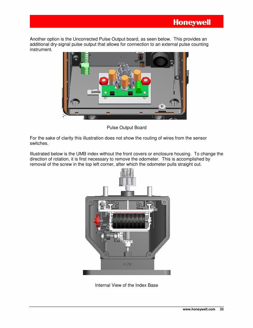
www.honeywell.com 33
Another option is the Uncorrected Pulse Output board, as seen below. This provides an additional dry-signal pulse output that allows for connection to an external pulse counting instrument.
Pulse Output Board
For the sake of clarity this illustration does not show the routing of wires from the sensor switches.
Illustrated below is the UMB index without the front covers or enclosure housing. To change the direction of rotation, it is first necessary to remove the odometer. This is accomplished by removal of the screw in the top left corner, after which the odometer pulls straight out.
Internal View of the Index Base

www.honeywell.com 34
A small Allen wrench tool is included with the index. Loosen the set screws on the top and bottom miter gears and swap the gear that engages. Shift the gear set upwards for meters with CW rotation and down for meters with CCW rotation. See the gear detail drawing below. After the gears are securely set, check for good gear engagement that is neither too loose (causing gear skipping) or too tight (causing gear binding). Then reinstall the odometer.
Rotation Gears within the Index Base
As a final note, it is also possible to change the number of digits visible on the mechanical odometer using horizontal sliding “windows”. Up to three digits can be masked-off from the right side, and/or up to three digits from the left side.
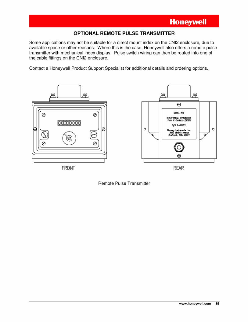
www.honeywell.com 35
OPTIONAL REMOTE PULSE TRANSMITTER
Some applications may not be suitable for a direct mount index on the CNI2 enclosure, due to available space or other reasons. Where this is the case, Honeywell also offers a remote pulse transmitter with mechanical index display. Pulse switch wiring can then be routed into one of the cable fittings on the CNI2 enclosure. Contact a Honeywell Product Support Specialist for additional details and ordering options.
Remote Pulse Transmitter
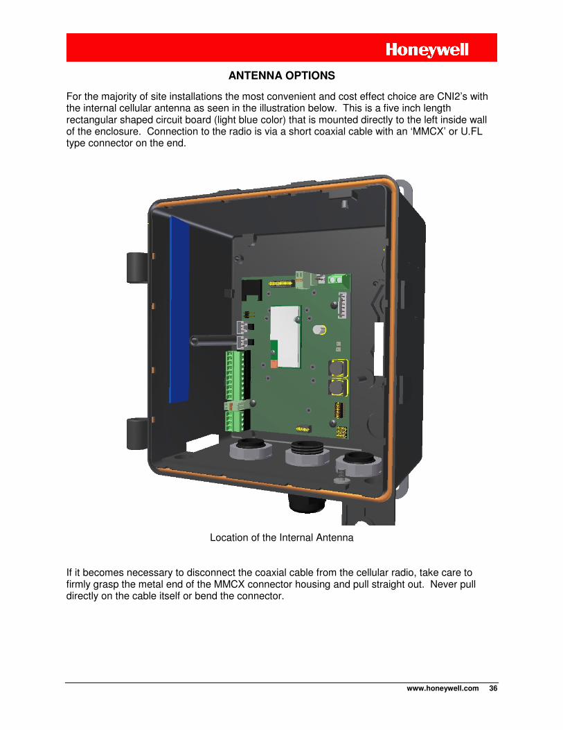
www.honeywell.com 36
ANTENNA OPTIONS
For the majority of site installations the most convenient and cost effect choice are CNI2’s with the internal cellular antenna as seen in the illustration below. This is a five inch length rectangular shaped circuit board (light blue color) that is mounted directly to the left inside wall of the enclosure. Connection to the radio is via a short coaxial cable with an ‘MMCX’ or U.FL type connector on the end.
Location of the Internal Antenna
If it becomes necessary to disconnect the coaxial cable from the cellular radio, take care to firmly grasp the metal end of the MMCX connector housing and pull straight out. Never pull directly on the cable itself or bend the connector.
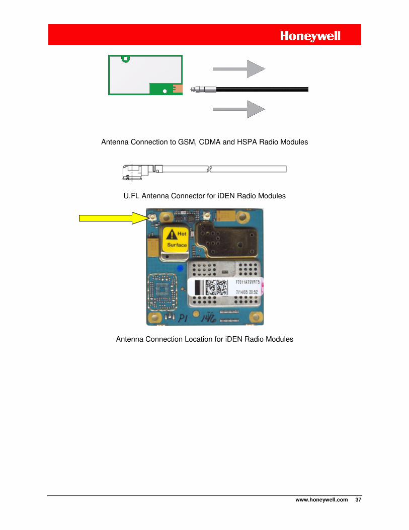
www.honeywell.com 37
Antenna Connection to GSM, CDMA and HSPA Radio Modules
U.FL Antenna Connector for iDEN Radio Modules
Antenna Connection Location for iDEN Radio Modules

www.honeywell.com 38
Where cellular signal reception is problematic, due to either terrain or proximity to cellular towers, it may be necessary to use an external antenna instead. This option is available in the
form of a bulkhead N-Fitting (jack or female) mount as seen in the illustration. An external antenna can then be elevated as required and directionally pointed to the nearest cell tower.
Bottom View with External RF Connector

www.honeywell.com 39
TAMPER DETECT & CALL SWITCH OPTIONS
The figure below illustrates where two magnetic detect switches are located within the CNI2. At the bottom left corner is a seen a small white magnetic switch which has been wired into the J9 connector. This enables a field technician to swipe a hand-held magnet wand (part no. 20-7286) near the bottom left side in order to initiate a call. In cases where the CNI2 enclosure is sealed with a lock or wire seal, this form of call trigger is very convenient.
Location of the TAMPER and CALL Switches
The white rectangular TAMPER detect switch is seen on the right-center inside wall. Not shown here is the actuating magnet attached to the front door. When the door is opened the switch activates and can generate an immediate call into the central office, or the event will be reported on the next scheduled call.
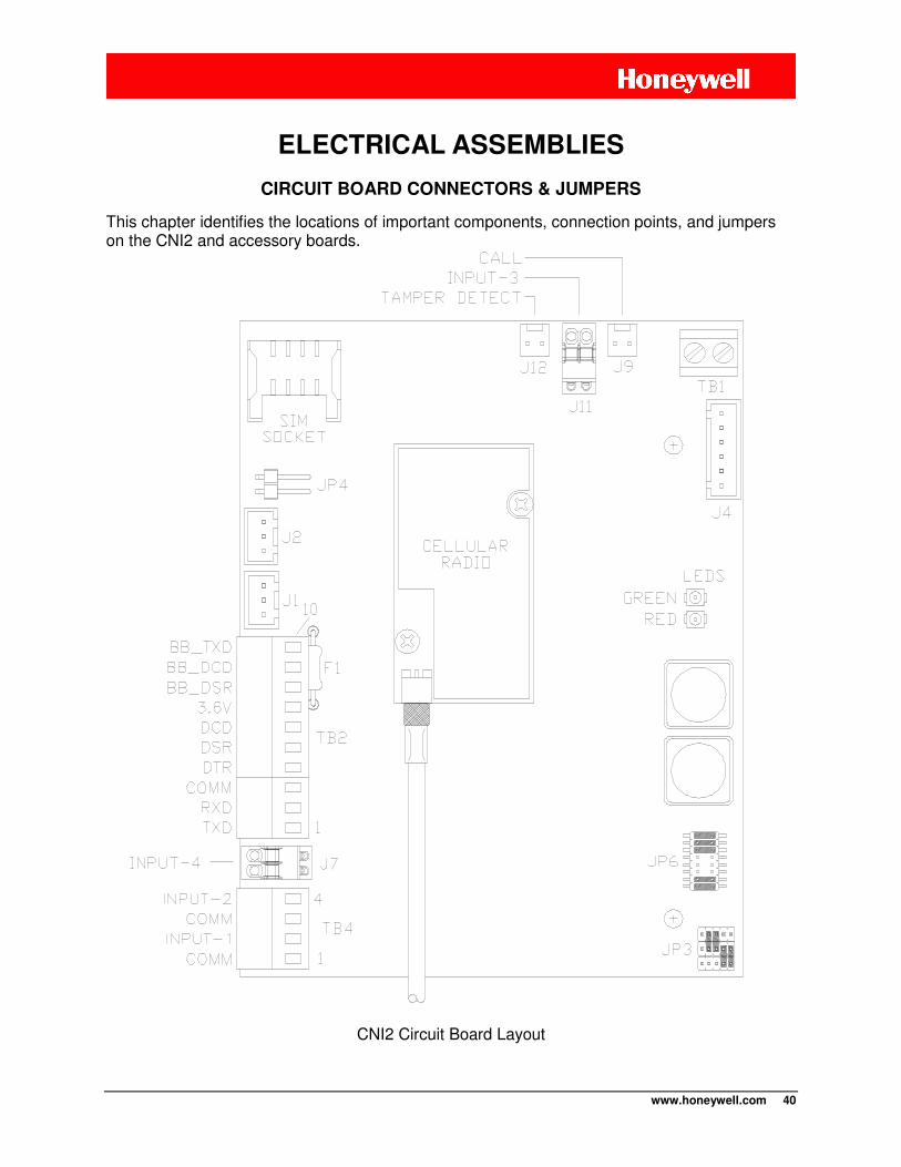
www.honeywell.com 40
CIRCUIT BOARD CONNECTORS & JUMPERS
This chapter identifies the locations of important components, connection points, and jumpers on the CNI2 and accessory boards.
CNI2 Circuit Board Layout
ELECTRICAL ASSEMBLIES
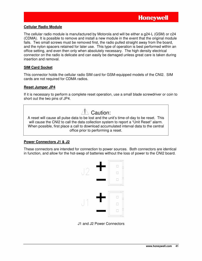
www.honeywell.com 41
Cellular Radio Module
The cellular radio module is manufactured by Motorola and will be either a g24-L (GSM) or c24 (CDMA). It is possible to remove and install a new module in the event that the original module fails. Two small screws must be removed first, the radio pulled straight away from the board, and the nylon spacers retained for later use. This type of operation is best performed within an office setting, and even then only when absolutely necessary. The high density electrical connector on the radio is delicate and can easily be damaged unless great care is taken during insertion and removal.
SIM Card Socket
This connector holds the cellular radio SIM card for GSM-equipped models of the CNI2. SIM cards are not required for CDMA radios.
Reset Jumper JP4
If it is necessary to perform a complete reset operation, use a small blade screwdriver or coin to short out the two pins of JP4.
Caution: A reset will cause all pulse data to be lost and the unit’s time-of-day to be reset. This will cause the CNI2 to call the data collection system to report a “Unit Reset” alarm.
When possible, first place a call to download accumulated interval data to the central office prior to performing a reset.
Power Connectors J1 & J2
These connectors are intended for connection to power sources. Both connectors are identical in function, and allow for the hot-swap of batteries without the loss of power to the CNI2 board.
J1 and J2 Power Connectors
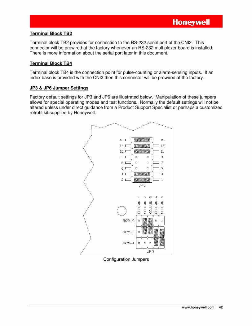
www.honeywell.com 42
Terminal Block TB2
Terminal block TB2 provides for connection to the RS-232 serial port of the CNI2. This connector will be prewired at the factory whenever an RS-232 multiplexer board is installed. There is more information about the serial port later in this document. Terminal Block TB4
Terminal block TB4 is the connection point for pulse-counting or alarm-sensing inputs. If an index base is provided with the CNI2 then this connector will be prewired at the factory. JP3 & JP6 Jumper Settings
Factory default settings for JP3 and JP6 are illustrated below. Manipulation of these jumpers allows for special operating modes and test functions. Normally the default settings will not be altered unless under direct guidance from a Product Support Specialist or perhaps a customized retrofit kit supplied by Honeywell.
Configuration Jumpers
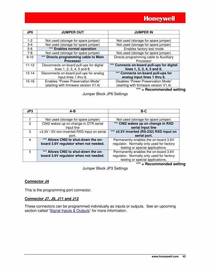
www.honeywell.com 43
JP6 JUMPER OUT JUMPER IN
1-2 Not used (storage for spare jumper) Not used (storage for spare jumper) 3-4 Not used (storage for spare jumper) Not used (storage for spare jumper) 5-6 *** Enables normal operation Enables factory test mode 7-8 Not used (storage for spare jumper) Not used (storage for spare jumper) 9-10 *** Directs programming cable to Main
Processor Directs programming cable to Auxilliary
Processor 11-12 Disconnects on-board pull-ups for digital
lines 1, 2, 3, 4, 5 and 8. *** Connects on-board pull-ups for digital
lines 1, 2, 3, 4, 5 and 8.
13-14 Disconnects on-board pull-ups for analog input lines 1 thru 6.
*** Connects on-board pull-ups for analog input lines 1 thru 6.
15-16 Enables “Power Preservation Mode” (starting with firmware version V1.4)
Disables “Power Preservation Mode” (starting with firmware version V1.4)
*** = Recommended setting Jumper Block JP6 Settings
JP3 A-B B-C
1 Not used (storage for spare jumper) Not used (storage for spare jumper) 2 CNI2 wakes up on change in DTR serial
input line *** CNI2 wakes up on change in RXD
serial input line
3 +3.3V / 0V non-inverted RXD input on serial port.
*** ±5.5V inverted (RS-232) RXD input on serial port.
4 *** Allows CNI2 to shut-down the on-board 3.6V regulator when not needed.
Permanently enables the on-board 3.6V regulator. Normally only used for factory
testing or special applications. 5 *** Allows CNI2 to shut-down the on-
board 3.6V regulator when not needed. Permanently enables the on-board 3.6V regulator. Normally only used for factory
testing or special applications.
*** = Recommended setting Jumper Block JP3 Settings
Connector J4
This is the programming port connector.
Connector J7, J9, J11 and J12
These connectors can be programmed individually as inputs or outputs. See an upcoming section called “Signal Inputs & Outputs” for more information.
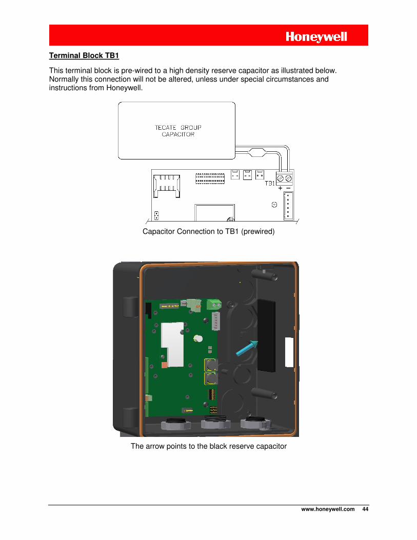
www.honeywell.com 44
Terminal Block TB1
This terminal block is pre-wired to a high density reserve capacitor as illustrated below. Normally this connection will not be altered, unless under special circumstances and instructions from Honeywell.
Capacitor Connection to TB1 (prewired)
The arrow points to the black reserve capacitor
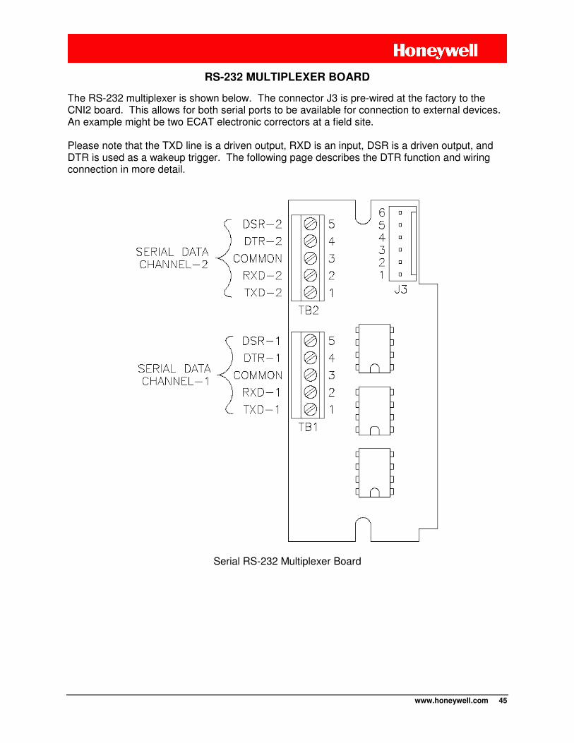
www.honeywell.com 45
RS-232 MULTIPLEXER BOARD
The RS-232 multiplexer is shown below. The connector J3 is pre-wired at the factory to the CNI2 board. This allows for both serial ports to be available for connection to external devices. An example might be two ECAT electronic correctors at a field site. Please note that the TXD line is a driven output, RXD is an input, DSR is a driven output, and DTR is used as a wakeup trigger. The following page describes the DTR function and wiring connection in more detail.
Serial RS-232 Multiplexer Board
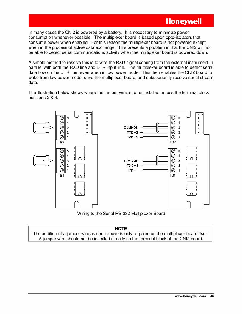
www.honeywell.com 46
In many cases the CNI2 is powered by a battery. It is necessary to minimize power consumption whenever possible. The multiplexer board is based upon opto-isolators that consume power when enabled. For this reason the multiplexer board is not powered except when in the process of active data exchange. This presents a problem in that the CNI2 will not be able to detect serial communications activity when the multiplexer board is powered down. A simple method to resolve this is to wire the RXD signal coming from the external instrument in parallel with both the RXD line and DTR input line. The multiplexer board is able to detect serial data flow on the DTR line, even when in low power mode. This then enables the CNI2 board to wake from low power mode, drive the multiplexer board, and subsequently receive serial stream data. The illustration below shows where the jumper wire is to be installed across the terminal block positions 2 & 4.
Wiring to the Serial RS-232 Multiplexer Board
NOTE The addition of a jumper wire as seen above is only required on the multiplexer board itself.
A jumper wire should not be installed directly on the terminal block of the CNI2 board.
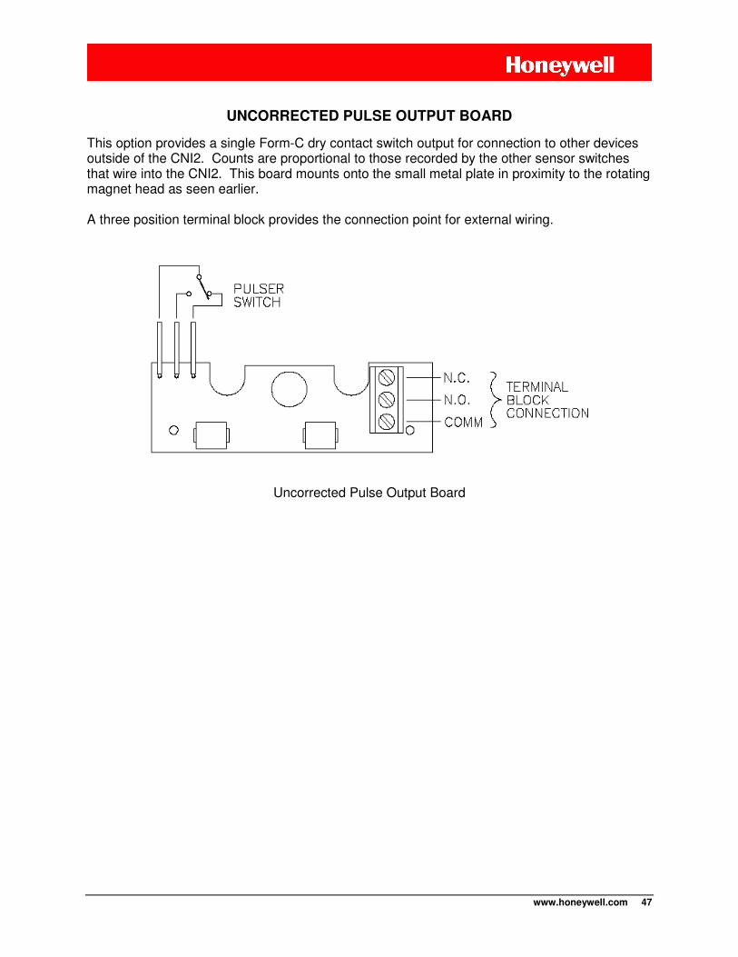
www.honeywell.com 47
UNCORRECTED PULSE OUTPUT BOARD
This option provides a single Form-C dry contact switch output for connection to other devices outside of the CNI2. Counts are proportional to those recorded by the other sensor switches that wire into the CNI2. This board mounts onto the small metal plate in proximity to the rotating magnet head as seen earlier. A three position terminal block provides the connection point for external wiring.
Uncorrected Pulse Output Board
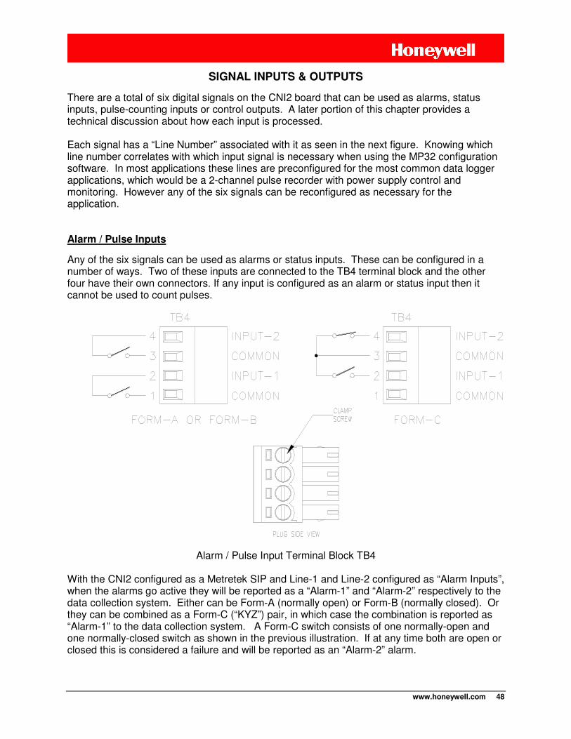
www.honeywell.com 48
SIGNAL INPUTS & OUTPUTS
There are a total of six digital signals on the CNI2 board that can be used as alarms, status inputs, pulse-counting inputs or control outputs. A later portion of this chapter provides a technical discussion about how each input is processed. Each signal has a “Line Number” associated with it as seen in the next figure. Knowing which line number correlates with which input signal is necessary when using the MP32 configuration software. In most applications these lines are preconfigured for the most common data logger applications, which would be a 2-channel pulse recorder with power supply control and monitoring. However any of the six signals can be reconfigured as necessary for the application. Alarm / Pulse Inputs
Any of the six signals can be used as alarms or status inputs. These can be configured in a number of ways. Two of these inputs are connected to the TB4 terminal block and the other four have their own connectors. If any input is configured as an alarm or status input then it cannot be used to count pulses.
Alarm / Pulse Input Terminal Block TB4
With the CNI2 configured as a Metretek SIP and Line-1 and Line-2 configured as “Alarm Inputs”, when the alarms go active they will be reported as a “Alarm-1” and “Alarm-2” respectively to the data collection system. Either can be Form-A (normally open) or Form-B (normally closed). Or they can be combined as a Form-C (“KYZ”) pair, in which case the combination is reported as “Alarm-1” to the data collection system. A Form-C switch consists of one normally-open and one normally-closed switch as shown in the previous illustration. If at any time both are open or closed this is considered a failure and will be reported as an “Alarm-2” alarm.
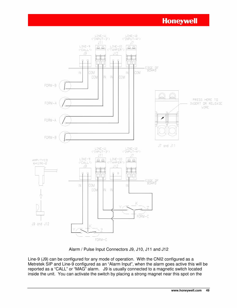
www.honeywell.com 49
Alarm / Pulse Input Connectors J9, J10, J11 and J12
Line-9 (J9) can be configured for any mode of operation. With the CNI2 configured as a Metretek SIP and Line-9 configured as an “Alarm Input”, when the alarm goes active this will be reported as a “CALL” or “MAG” alarm. J9 is usually connected to a magnetic switch located inside the unit. You can activate the switch by placing a strong magnet near this spot on the

www.honeywell.com 50
outside of the enclosure. Alternatively the switch can be a simple pushbutton switch located inside the unit or protruding from the wall of the enclosure. Or you can just momentarily short the J9 pins with a screwdriver or coin. Line-10 (J12) can be configured for any mode of operation. With the CNI2 configured as a Metretek SIP and Line-10 configured as an “Alarm Input”, when the alarm goes active this will be reported as a “TAMPER” alarm. J12 is often connected to a magnetic switch mounted to the side of the enclosure and a magnet on the door. When the door is opened the magnet and switch separate and generate an alarm. This is often used to detect intrusion as well as to record service events. You can also combine Line-9 and Line-10 together as a Form-C (“KYZ”) pair. A Form-C switch consists of one normally-open and one normally-closed switch as shown in the previous illustration. With the CNI2 configured as a Metretek SIP and Line-9 and -10 configured as “Alarm Inputs”, when the switch goes active it is reported as a “CALL” alarm to the data collection system. If at any time both switches are open or closed at the same time this is considered a failure and will be reported as a “TAMPER” alarm. Line-11 (J11) can be configured for any mode of operation. The most common use is an alarm input or a pulse-counting input. To facilitate easier connection this is a two-piece “pluggable” connector. With the CNI2 configured as a Metretek SIP and Line-11 configured as an “Alarm Input”, when the alarm goes active this will be reported as an “AC-OFF” alarm. When it returns to an inactive state an “AC-ON” alarm will be reported. Line-12 (J7) can be configured for any mode of operation. The most common use is an alarm input or a pulse-counting input. To facilitate easier connection this is a two-piece “pluggable” connector. If Line-12 is configured as a “Special Purpose Output”, the line will go active several 100 milliseconds before the radio is powered up, and will go inactive several 100 milliseconds after the radio is powered down. This signal can be used to control an external power source. You can also combine the Line-11 and Line-12 inputs together as a Form-C (“KYZ”) pair as shown in the previous illustration.
www.honeywell.com 51
Pulse Counting Inputs
Any of the six signals can be used as pulse-counting inputs, but no more than four can be configured this way because that’s all the data collection system will accept. If the CNI2 is configured as a Mercury Mini-Max or Pulse Accumulator, the only two pulse-counting inputs can be reported. If any input is configured as a pulse-counting input then it cannot be used as an alarm or status input. Pulse-counting inputs can be either Form-A, Form-B or Form-C switches.
Outputs
Any of the six signals can be configured as outputs. These are low-level (+3.3V) logic signals with very low current (2 mA) capabilities. In many cases these signals will need additional amplification or conversion by external equipment.
WARNING An output has strict limitations with respect to voltage and current. See the specifications section to avoid damage to the CNI2 board.
• Output Under Host Control: This configuration can be used to control external
equipment from the central office, such as a warning light, an audio alarm or a pump. This is only supported when the CNI2 is configured as a Metretek SIP and when using the “Relay Settings” feature in the DC-2009® data collection system. The output is changed to the new setting only after a successful call.
• Output Follows Input #”: In this configuration the output follows any one of the inputs
(“repeater”). This allows other external equipment to have access to the same pulse or alarm information that is being processed by the CNI2.
• Special Purpose Output: This type of output is controlled by the CNI2 for special purpose applications.
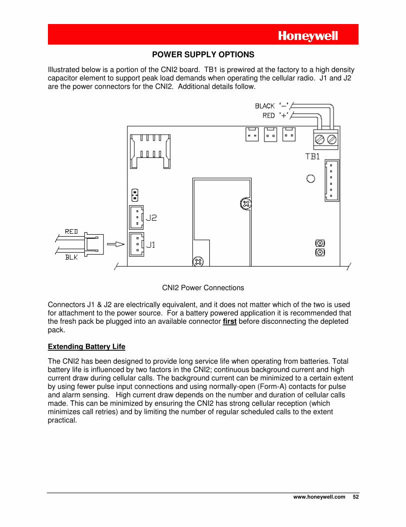
www.honeywell.com 52
POWER SUPPLY OPTIONS
Illustrated below is a portion of the CNI2 board. TB1 is prewired at the factory to a high density capacitor element to support peak load demands when operating the cellular radio. J1 and J2 are the power connectors for the CNI2. Additional details follow.
CNI2 Power Connections
Connectors J1 & J2 are electrically equivalent, and it does not matter which of the two is used for attachment to the power source. For a battery powered application it is recommended that the fresh pack be plugged into an available connector first before disconnecting the depleted pack.
Extending Battery Life
The CNI2 has been designed to provide long service life when operating from batteries. Total battery life is influenced by two factors in the CNI2; continuous background current and high current draw during cellular calls. The background current can be minimized to a certain extent by using fewer pulse input connections and using normally-open (Form-A) contacts for pulse and alarm sensing. High current draw depends on the number and duration of cellular calls made. This can be minimized by ensuring the CNI2 has strong cellular reception (which minimizes call retries) and by limiting the number of regular scheduled calls to the extent practical.
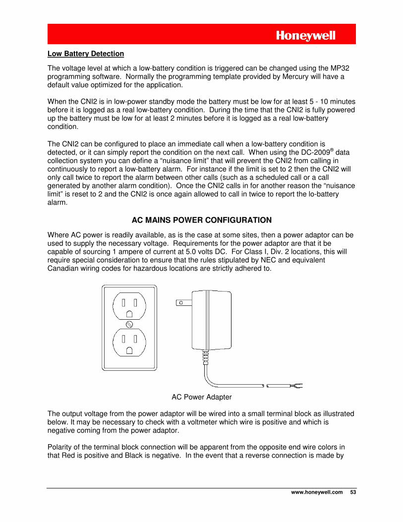
www.honeywell.com 53
Low Battery Detection
The voltage level at which a low-battery condition is triggered can be changed using the MP32 programming software. Normally the programming template provided by Mercury will have a default value optimized for the application. When the CNI2 is in low-power standby mode the battery must be low for at least 5 - 10 minutes before it is logged as a real low-battery condition. During the time that the CNI2 is fully powered up the battery must be low for at least 2 minutes before it is logged as a real low-battery condition.
The CNI2 can be configured to place an immediate call when a low-battery condition is detected, or it can simply report the condition on the next call. When using the DC-2009® data collection system you can define a “nuisance limit” that will prevent the CNI2 from calling in continuously to report a low-battery alarm. For instance if the limit is set to 2 then the CNI2 will only call twice to report the alarm between other calls (such as a scheduled call or a call generated by another alarm condition). Once the CNI2 calls in for another reason the “nuisance limit” is reset to 2 and the CNI2 is once again allowed to call in twice to report the lo-battery alarm.
AC MAINS POWER CONFIGURATION
Where AC power is readily available, as is the case at some sites, then a power adaptor can be used to supply the necessary voltage. Requirements for the power adaptor are that it be capable of sourcing 1 ampere of current at 5.0 volts DC. For Class I, Div. 2 locations, this will require special consideration to ensure that the rules stipulated by NEC and equivalent Canadian wiring codes for hazardous locations are strictly adhered to.
AC Power Adapter
The output voltage from the power adaptor will be wired into a small terminal block as illustrated below. It may be necessary to check with a voltmeter which wire is positive and which is negative coming from the power adaptor. Polarity of the terminal block connection will be apparent from the opposite end wire colors in that Red is positive and Black is negative. In the event that a reverse connection is made by

www.honeywell.com 54
accident, no harm will be caused to the electronics aside from the fact that the CNI2 will not power as expected.
External Power Tie-In Block
A lithium or Alkaline battery pack can be connected to the vacant J1 / J2 power connector to supply continuous power in the event of AC mains failure. Lithium batteries have a longer ‘shelf-life’ as compared to alkaline batteries, and are normally regarded as the superior choice for long term backup applications.
SOLAR POWER CONFIGURATION
Solar power is also a possibility, although it will be necessary to also provide a voltage charge regulator and lead acid battery as seen in the illustration. Wiring to the terminal block illustrated previously will be the same as was the case for the AC mains application. The lead acid battery serves as the backup source during the evening and cloudy days. Correct sizing of the solar panel and lead acid battery are necessary for a given territorial region. Application notes are available from solar panel suppliers to assist in the process of sizing the panel and battery.
Typical Solar Power System
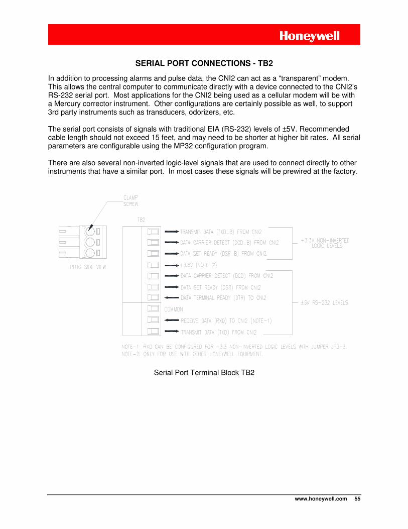
www.honeywell.com 55
SERIAL PORT CONNECTIONS - TB2
In addition to processing alarms and pulse data, the CNI2 can act as a “transparent” modem. This allows the central computer to communicate directly with a device connected to the CNI2’s RS-232 serial port. Most applications for the CNI2 being used as a cellular modem will be with a Mercury corrector instrument. Other configurations are certainly possible as well, to support 3rd party instruments such as transducers, odorizers, etc. The serial port consists of signals with traditional EIA (RS-232) levels of ±5V. Recommended cable length should not exceed 15 feet, and may need to be shorter at higher bit rates. All serial parameters are configurable using the MP32 configuration program. There are also several non-inverted logic-level signals that are used to connect directly to other instruments that have a similar port. In most cases these signals will be prewired at the factory.
Serial Port Terminal Block TB2
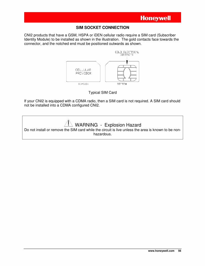
www.honeywell.com 56
SIM SOCKET CONNECTION
CNI2 products that have a GSM, HSPA or iDEN cellular radio require a SIM card (Subscriber Identity Module) to be installed as shown in the illustration. The gold contacts face towards the connector, and the notched end must be positioned outwards as shown.
Typical SIM Card
If your CNI2 is equipped with a CDMA radio, then a SIM card is not required. A SIM card should not be installed into a CDMA configured CNI2.
WARNING - Explosion Hazard Do not install or remove the SIM card while the circuit is live unless the area is known to be non-
hazardous.
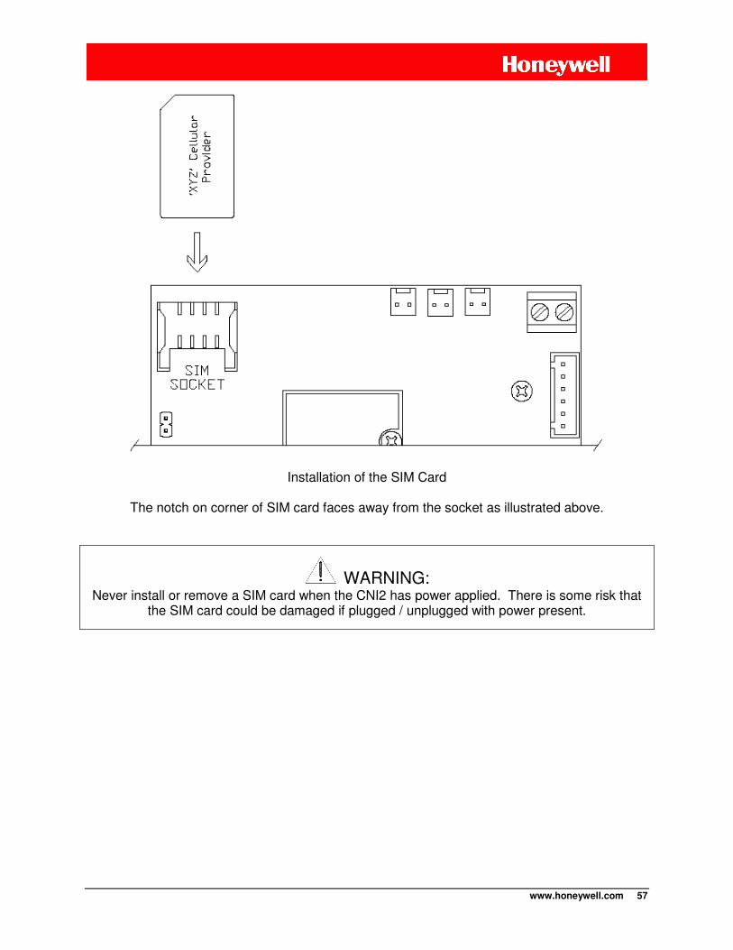
www.honeywell.com 57
Installation of the SIM Card
The notch on corner of SIM card faces away from the socket as illustrated above.
WARNING: Never install or remove a SIM card when the CNI2 has power applied. There is some risk that
the SIM card could be damaged if plugged / unplugged with power present.
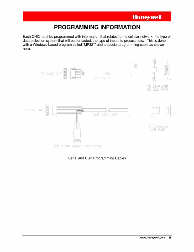
www.honeywell.com 58
Each CNI2 must be programmed with information that relates to the cellular network, the type of data collection system that will be contacted, the type of inputs to process, etc. This is done with a Windows-based program called “MP32®” and a special programming cable as shown here.
Serial and USB Programming Cables
PROGRAMMING INFORMATION
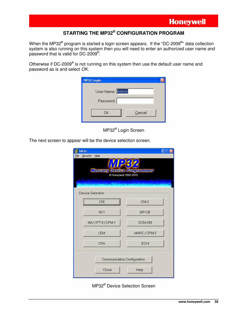
www.honeywell.com 59
STARTING THE MP32® CONFIGURATION PROGRAM When the MP32® program is started a login screen appears. If the “DC-2009®” data collection system is also running on this system then you will need to enter an authorized user name and password that is valid for DC-2009®. Otherwise if DC-2009® is not running on this system then use the default user name and password as is and select OK.
MP32® Login Screen The next screen to appear will be the device selection screen.
MP32® Device Selection Screen
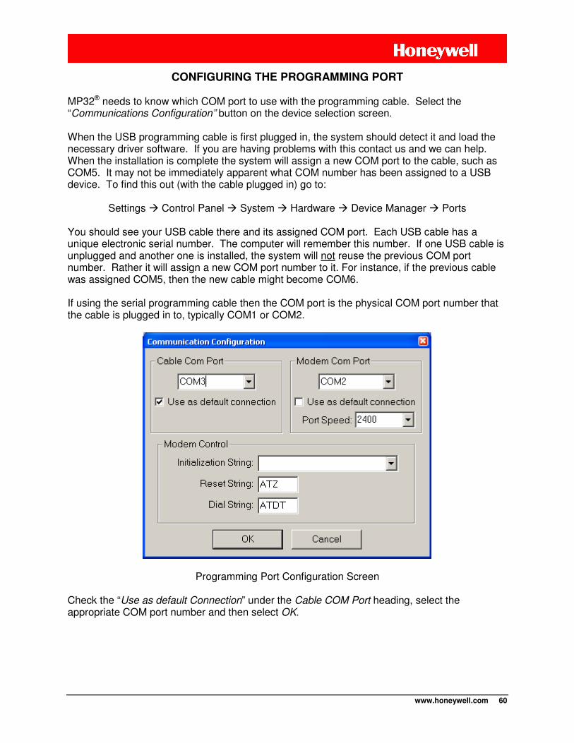
www.honeywell.com 60
CONFIGURING THE PROGRAMMING PORT MP32® needs to know which COM port to use with the programming cable. Select the “Communications Configuration” button on the device selection screen. When the USB programming cable is first plugged in, the system should detect it and load the necessary driver software. If you are having problems with this contact us and we can help. When the installation is complete the system will assign a new COM port to the cable, such as COM5. It may not be immediately apparent what COM number has been assigned to a USB device. To find this out (with the cable plugged in) go to:
Settings Control Panel System Hardware Device Manager Ports You should see your USB cable there and its assigned COM port. Each USB cable has a unique electronic serial number. The computer will remember this number. If one USB cable is unplugged and another one is installed, the system will not reuse the previous COM port number. Rather it will assign a new COM port number to it. For instance, if the previous cable was assigned COM5, then the new cable might become COM6.
If using the serial programming cable then the COM port is the physical COM port number that the cable is plugged in to, typically COM1 or COM2.
Programming Port Configuration Screen
Check the “Use as default Connection” under the Cable COM Port heading, select the appropriate COM port number and then select OK.
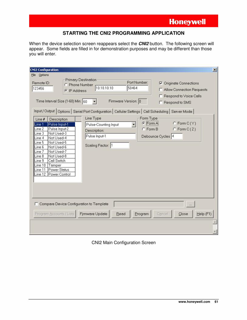
www.honeywell.com 61
STARTING THE CNI2 PROGRAMMING APPLICATION When the device selection screen reappears select the CNI2 button. The following screen will appear. Some fields are filled in for demonstration purposes and may be different than those you will enter.
CNI2 Main Configuration Screen
www.honeywell.com 62
MAIN SCREEN
Saving and Retrieving Configurations
A “configuration” is a set of parameters that will be programmed into the CNI2. It is also referred to as a “template”. Once you define a configuration it can be saved by using the FILE pull-down menu in the upper left-hand corner of the screen. A previously saved configuration can be opened in the same manner. This is useful if many units are to be programmed with similar information, such as all using the same destination IP addresses or cellular information.
To start a programming session either OPEN a previously saved template or manually enter all of the parameters. If you would like to work with the configuration that is already stored in the CNI2 you can perform a READ operation of the CNI2 with the programming cable installed and the unit powered up. The status of the operation is displayed on the bottom of the screen. The CANCEL button will terminate the session in the event there is no response or an error.
IMPORTANT NOTE Reading the configuration from a CNI2 automatically resets the unit and clears all
accumulated data. Remote Unit ID (RUID)
Each CNI2 must have a unique six-digit ID number. This is required by the data collection system. Legal values are 000000-FFFFFF (hexadecimal notation). Sequential numbering is not required, nor is it necessary to use any of the hexadecimal digits ‘A, B, C, D, E, or F’. Typically if you do not specify the ID number prior to shipment then the CNI2 is shipped with an RUID that is the last six digits of the serial number located on the front label. Primary Destination
CSD mode is similar to a dial-up connection on a wired phone line. CSD service is no longer offered by some cellular service providers. If the CNI2 is allowed to originate a CSD data call to another modem then it will need the phone number of that modem. Select the “Phone Number” button and enter up to 32 numeric digits. As with most cellular phones, it is usually necessary to enter the entire phone number, including area code, even if the call is local. For example in the U.S., a call to 555-1212 within area code 987 may have to be entered as 19875551212. If the CNI2 is to communicate via the Internet then it will need the IP address and port number of the data collection server. Your computer systems administrator usually assigns these values. Select the “IP Address” button. Then enter the address of the server expressed in “dotted decimal format”, such as 198.32.67.101. The data collection server is usually assigned a default port number of 50466, but the system administrator can change this. Do not use port numbers below 1024. The Primary Destination is used for scheduled calls, consumption-related alarms, page call-backs, low battery alarms, etc. Any hardware input that has been programmed as an alarm input can have its own unique destination. This will be discussed shortly.
www.honeywell.com 63
Originate Calls
Check this box if the CNI2 is allowed to originate CSD or Internet connections. This allows the CNI2 to call in at regularly scheduled times or whenever an alarm condition occurs. When using the Internet for communications the CNI2 acts as a “client”. It can only originate calls to the data collection system, which is considered an internet “server”. Allow Connection Requests
This setting allows the CNI2 to act as an Internet “server”, allowing it to be contacted via the Internet. When this box is checked the Server Mode configuration screen is used to define specific server features.
IMPORTANT NOTE The Allow Connection Requests feature requires the cellular radio to be powered up more
frequently. This will have a great impact on battery life. A permanent power source such as solar or AC is recommended if you wish to use this option.
Respond to Voice Calls / Respond to SMS
“Paging” is a mechanism that causes the CNI2 to call back to the Primary Destination on demand. You can page the CNI2 by calling its cellular voice number or by sending it a text message using SMS, or short message service. Your cellular account may not offer voice or SMS service. In addition to paging, if the CNI2 is configured for CSD mode then checking the “Respond to Voice Calls” box will allow the CNI2 to answer incoming CSD calls from the central office.
IMPORTANT NOTE The Respond to Voice Calls / Respond to SMS options are NOT recommended for battery-powered operation. These options require the cellular radio to be powered up at all times, which will quickly drain the CNI2’s batteries. A permanent power source such as solar or
AC is recommended if you wish to use these options. Time Interval Size
You can configure the CNI2 to count pulses from up to 6 sources. Pulses are counted over a specific time interval and the total for that period is saved as one record. It then starts the counting process over for the next time interval and this process continues indefinitely. The time interval can be 1, 2, 3, 5, 6, 10, 12, 15, 20, 30 or 60 minutes (anything evenly divisible into 60). A shorter time period allows you to observe small changes with more detail. But it also consumes storage space more quickly, causing the CNI2 to need to communicate with the data collection system more frequently so that older data is not lost. This can have an impact on both battery life and the cost of the cellular service. The CNI2 has the capacity to save a total of 30,000 records before it starts to overwrite the oldest records. These are divided equally between all active pulse-counting channels. If only one channel is used for pulse-counting then all 30,000 record locations will be used for that
www.honeywell.com 64
channel. If using a 10-minute interval it would take a little over 200 days to reach the end of the memory. If three channels are active then each channel is allocated 1/3 of the memory, or 10,000 records. If some of the pulse / alarm inputs are not being used for pulse-counting then they should be programmed as alarm inputs even if they are not going to be used for alarms. This will cause the memory to be divided between only those channels that will be counting pulses. The data collection system (DC-2009® or MV90®) must also be configured with the same interval size; otherwise the calls from the CNI2 will be rejected. Although the CNI2 can accept up to six channels of pulse information, DC-2009® or MV90® can only accept four. Firmware Version
The firmware version number is reported any time the configuration is read from the CNI2 using the programming cable. This value cannot be altered. Compare Device Configuration to Template
This feature is useful when programming many CNI2 devices with similar information. When the CNI2’s configuration is read it is compared to a configuration file (a “template”) of your choice. If there are any differences other than the unit’s ID number, they will be displayed. You can manually enter the filename of the template or use the browse button to locate it on your system.
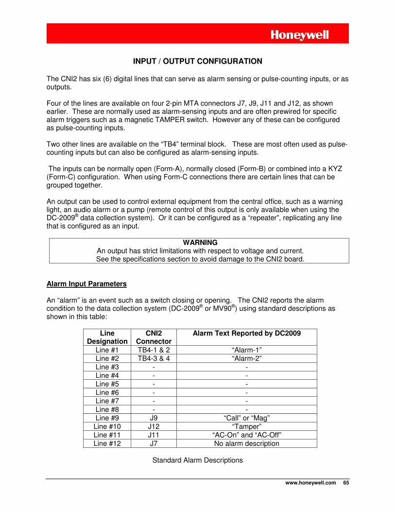
www.honeywell.com 65
INPUT / OUTPUT CONFIGURATION
The CNI2 has six (6) digital lines that can serve as alarm sensing or pulse-counting inputs, or as outputs. Four of the lines are available on four 2-pin MTA connectors J7, J9, J11 and J12, as shown earlier. These are normally used as alarm-sensing inputs and are often prewired for specific alarm triggers such as a magnetic TAMPER switch. However any of these can be configured as pulse-counting inputs. Two other lines are available on the “TB4” terminal block. These are most often used as pulse-counting inputs but can also be configured as alarm-sensing inputs. The inputs can be normally open (Form-A), normally closed (Form-B) or combined into a KYZ (Form-C) configuration. When using Form-C connections there are certain lines that can be grouped together. An output can be used to control external equipment from the central office, such as a warning light, an audio alarm or a pump (remote control of this output is only available when using the DC-2009® data collection system). Or it can be configured as a “repeater”, replicating any line that is configured as an input.
WARNING An output has strict limitations with respect to voltage and current. See the specifications section to avoid damage to the CNI2 board.
Alarm Input Parameters An “alarm” is an event such as a switch closing or opening. The CNI2 reports the alarm condition to the data collection system (DC-2009® or MV90®) using standard descriptions as shown in this table:
Line
Designation CNI2
Connector Alarm Text Reported by DC2009
Line #1 TB4-1 & 2 “Alarm-1” Line #2 TB4-3 & 4 “Alarm-2” Line #3 - - Line #4 - - Line #5 - - Line #6 - - Line #7 - - Line #8 - - Line #9 J9 “Call” or “Mag”
Line #10 J12 “Tamper” Line #11 J11 “AC-On” and “AC-Off” Line #12 J7 No alarm description
Standard Alarm Descriptions
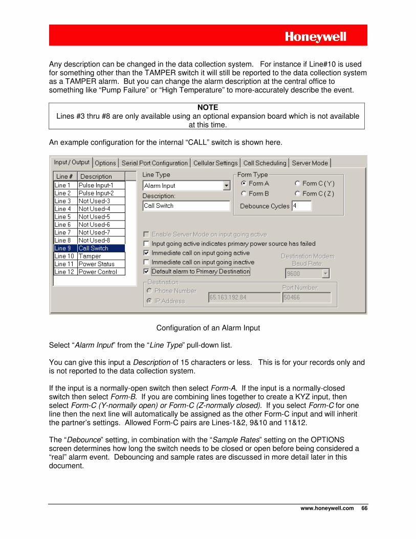
www.honeywell.com 66
Any description can be changed in the data collection system. For instance if Line#10 is used for something other than the TAMPER switch it will still be reported to the data collection system as a TAMPER alarm. But you can change the alarm description at the central office to something like “Pump Failure” or “High Temperature” to more-accurately describe the event.
NOTE Lines #3 thru #8 are only available using an optional expansion board which is not available
at this time. An example configuration for the internal “CALL” switch is shown here.
Configuration of an Alarm Input Select “Alarm Input” from the “Line Type” pull-down list. You can give this input a Description of 15 characters or less. This is for your records only and is not reported to the data collection system. If the input is a normally-open switch then select Form-A. If the input is a normally-closed switch then select Form-B. If you are combining lines together to create a KYZ input, then select Form-C (Y-normally open) or Form-C (Z-normally closed). If you select Form-C for one line then the next line will automatically be assigned as the other Form-C input and will inherit the partner’s settings. Allowed Form-C pairs are Lines-1&2, 9&10 and 11&12.
The “Debounce” setting, in combination with the “Sample Rates” setting on the OPTIONS screen determines how long the switch needs to be closed or open before being considered a “real” alarm event. Debouncing and sample rates are discussed in more detail later in this document.
www.honeywell.com 67
The “Immediate Call on Input Going Active” will cause the CNI2 to call immediately into the central office when the alarm event is sensed. The “Immediate Call on Input Going Inactive” will cause the CNI2 to call immediately into the central office when the alarm event ends. If neither box is checked then the alarm event will be reported on the next scheduled call.
NOTE Even if the “immediate call” boxes are checked the data collection system (DC-2009® or
MV90®) has the ability to override them.
The “Input Going Active Indicates Primary Power Source has Failed” is usually used in systems that contain a primary power source (ac or solar) and also an emergency backup battery. This puts the CNI2 into a low-power conservation mode until the alarm event is over. During this time some features may not be available. For instance if the CNI2 is configured to respond to SMS pages, which requires that the radio be powered up and running all the time, this mode will be temporarily suspended and the radio will be powered down until the primary power has been restored. By checking the “Default Alarm to Primary Destination” box the CNI2 will call into the Primary destination phone number or IP address. Otherwise you can specify a unique destination for each alarm. “Special Purpose” Input Parameters An input can be configured to perform a predefined function that does not relate to normal alarm-sensing or pulse-counting. At this time there are two functions:
1) Starting and ending “Power Preservation Mode”, which is a way to conserve power when a primary power source has failed. See the section called “Power Preservation Mode” for details.
2) Starting and / or ending what is called “Server Mode”. Server Mode allows the CNI2 to
accept connection requests from the central office over the Internet. In many cases the CNI2 will only enter Server Mode for brief periods throughout the day. One way to make this happen is to configure one of the inputs as a Server Mode control line. The next screen shot illustrates how Line-12 (connector J7) is used for this purpose. The Line Type is chosen to be “Special Purpose Input”. The input is configured as a Form-A (normally open) input. When the “Enable Server Mode on Input Going Active” box is checked two more selections will appear. One selection will terminate the Server Mode after a user-defined time period (in the Server Mode configuration screen). The other selection will terminate the Server Mode when the input returns to the inactive (open) state. See the section called “Server Mode” for many more details.
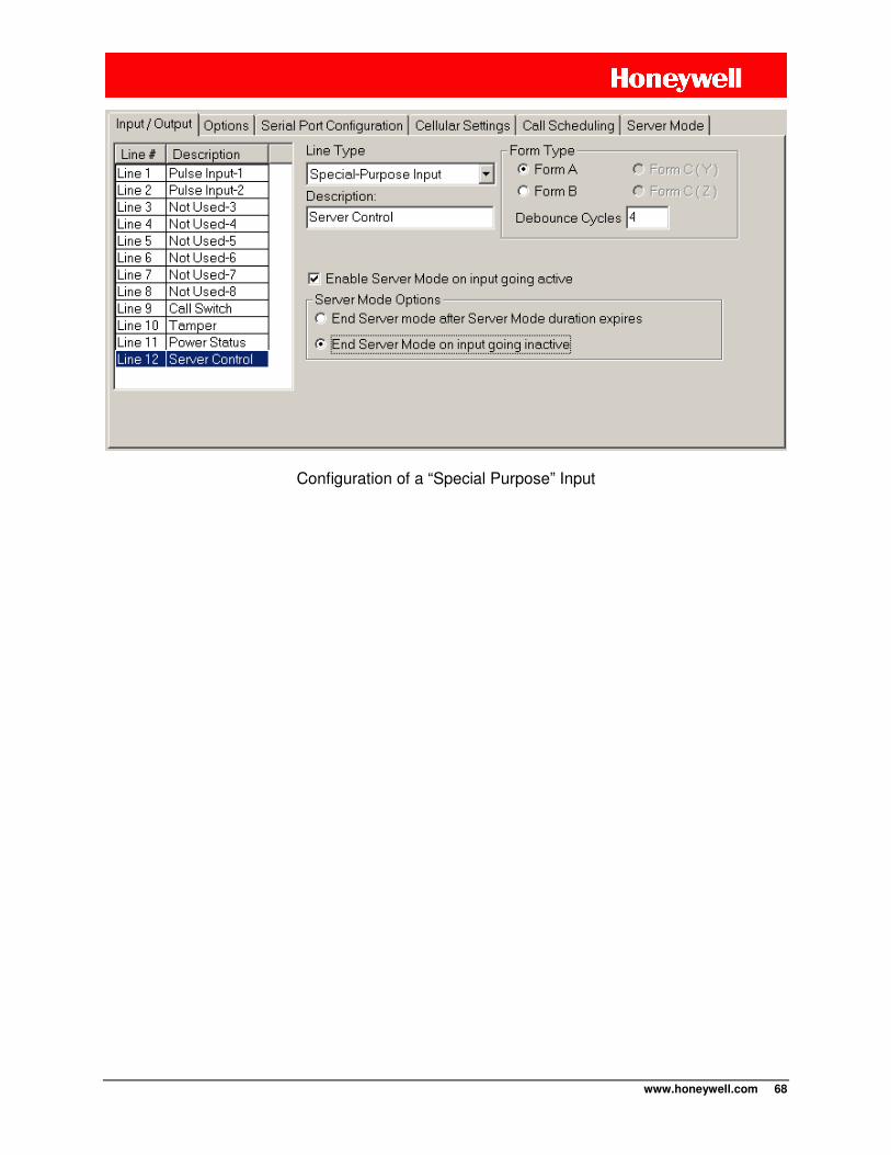
www.honeywell.com 68
Configuration of a “Special Purpose” Input
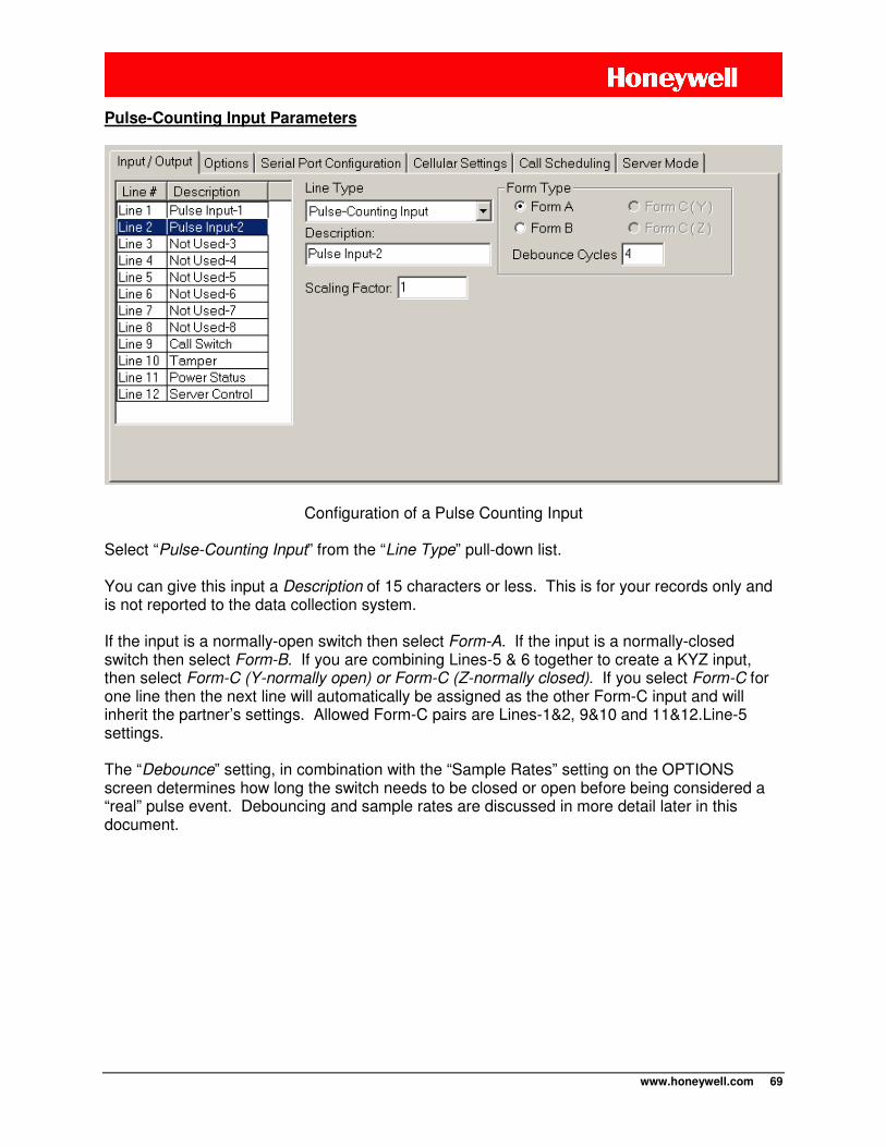
www.honeywell.com 69
Pulse-Counting Input Parameters
Configuration of a Pulse Counting Input Select “Pulse-Counting Input” from the “Line Type” pull-down list. You can give this input a Description of 15 characters or less. This is for your records only and is not reported to the data collection system. If the input is a normally-open switch then select Form-A. If the input is a normally-closed switch then select Form-B. If you are combining Lines-5 & 6 together to create a KYZ input, then select Form-C (Y-normally open) or Form-C (Z-normally closed). If you select Form-C for one line then the next line will automatically be assigned as the other Form-C input and will inherit the partner’s settings. Allowed Form-C pairs are Lines-1&2, 9&10 and 11&12.Line-5 settings.
The “Debounce” setting, in combination with the “Sample Rates” setting on the OPTIONS screen determines how long the switch needs to be closed or open before being considered a “real” pulse event. Debouncing and sample rates are discussed in more detail later in this document.
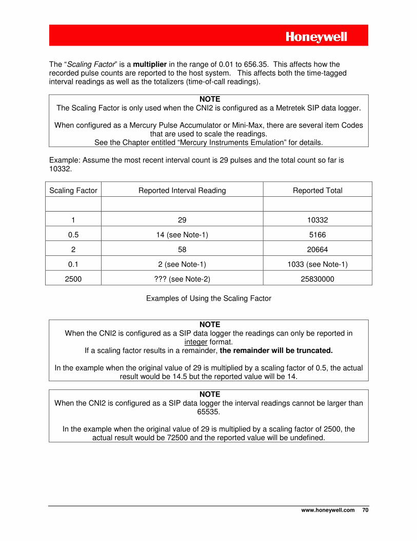
www.honeywell.com 70
The “Scaling Factor” is a multiplier in the range of 0.01 to 656.35. This affects how the recorded pulse counts are reported to the host system. This affects both the time-tagged interval readings as well as the totalizers (time-of-call readings).
NOTE The Scaling Factor is only used when the CNI2 is configured as a Metretek SIP data logger.
When configured as a Mercury Pulse Accumulator or Mini-Max, there are several item Codes
that are used to scale the readings. See the Chapter entitled “Mercury Instruments Emulation” for details.
Example: Assume the most recent interval count is 29 pulses and the total count so far is 10332.
Scaling Factor Reported Interval Reading Reported Total
1 29 10332
0.5 14 (see Note-1) 5166
2 58 20664
0.1 2 (see Note-1) 1033 (see Note-1)
2500 ??? (see Note-2) 25830000
Examples of Using the Scaling Factor
NOTE When the CNI2 is configured as a SIP data logger the readings can only be reported in
integer format. If a scaling factor results in a remainder, the remainder will be truncated.
In the example when the original value of 29 is multiplied by a scaling factor of 0.5, the actual
result would be 14.5 but the reported value will be 14.
NOTE When the CNI2 is configured as a SIP data logger the interval readings cannot be larger than
65535.
In the example when the original value of 29 is multiplied by a scaling factor of 2500, the actual result would be 72500 and the reported value will be undefined.
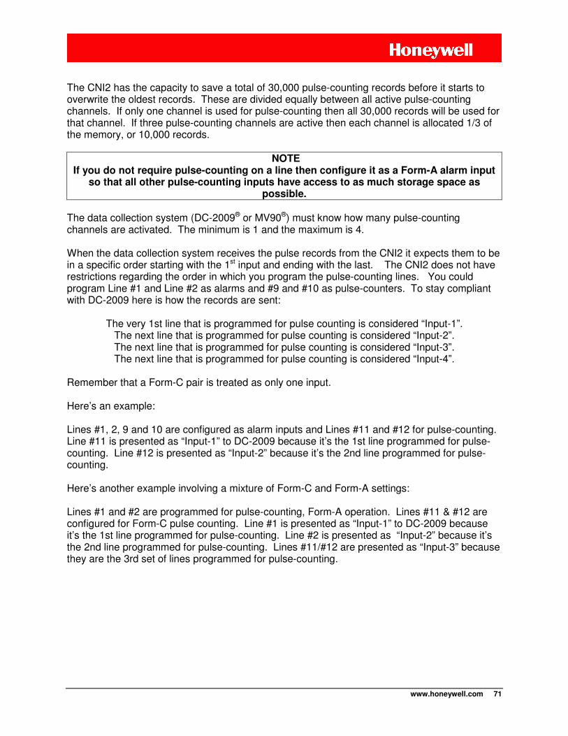
www.honeywell.com 71
The CNI2 has the capacity to save a total of 30,000 pulse-counting records before it starts to overwrite the oldest records. These are divided equally between all active pulse-counting channels. If only one channel is used for pulse-counting then all 30,000 records will be used for that channel. If three pulse-counting channels are active then each channel is allocated 1/3 of the memory, or 10,000 records.
NOTE If you do not require pulse-counting on a line then configure it as a Form-A alarm input
so that all other pulse-counting inputs have access to as much storage space as possible.
The data collection system (DC-2009® or MV90®) must know how many pulse-counting channels are activated. The minimum is 1 and the maximum is 4. When the data collection system receives the pulse records from the CNI2 it expects them to be in a specific order starting with the 1st input and ending with the last. The CNI2 does not have restrictions regarding the order in which you program the pulse-counting lines. You could program Line #1 and Line #2 as alarms and #9 and #10 as pulse-counters. To stay compliant with DC-2009 here is how the records are sent:
The very 1st line that is programmed for pulse counting is considered “Input-1”.
The next line that is programmed for pulse counting is considered “Input-2”. The next line that is programmed for pulse counting is considered “Input-3”. The next line that is programmed for pulse counting is considered “Input-4”.
Remember that a Form-C pair is treated as only one input. Here’s an example: Lines #1, 2, 9 and 10 are configured as alarm inputs and Lines #11 and #12 for pulse-counting. Line #11 is presented as “Input-1” to DC-2009 because it’s the 1st line programmed for pulse-counting. Line #12 is presented as “Input-2” because it’s the 2nd line programmed for pulse-counting. Here’s another example involving a mixture of Form-C and Form-A settings: Lines #1 and #2 are programmed for pulse-counting, Form-A operation. Lines #11 & #12 are configured for Form-C pulse counting. Line #1 is presented as “Input-1” to DC-2009 because it’s the 1st line programmed for pulse-counting. Line #2 is presented as “Input-2” because it’s the 2nd line programmed for pulse-counting. Lines #11/#12 are presented as “Input-3” because they are the 3rd set of lines programmed for pulse-counting.
www.honeywell.com 72
Output Parameters
An output line can be configured three ways. There is more information about using the outputs in the Technical Information section of this document. You can give this input a Description of 15 characters or less. This is for your records only and is not reported to the data collection system. Output Under Host Control
DC-2009® has the ability to control up to 3 output lines. These can be used to activate external equipment such as pumps or audible alarms. These outputs are controlled using the “Relay Information” screen in DC-2009’s “Remote Unit Configuration” program. This is discussed in an upcoming chapter.
There are no restrictions on which digital signals can be programmed as outputs. But DC-2009 refers to Relay Numbers-1, 2 and 3. So here is how the CNI2 handles this:
The very 1st line that is programmed as a host-controlled output is considered “Relay-1”. The next line that is programmed as a host-controlled is considered “Relay-2”. The next line that is programmed as a host-controlled is considered “Relay-3”.
Output Follows Input
When a line is programmed as an alarm or pulse-counting input its state can be replicated on any one of the output lines, within the frequency limits of the CNI2. This allows other pulse-counting or alarm-sensing equipment to have access to the same information. For instance the CNI2 may be counting pulses and there may be another piece of equipment located nearby that needs to count these pulses too. The CNI2 can be programmed to transmit a replica of the input signal to this other piece of equipment. To use this feature select the desired output line. Then from the selection list choose the “Output Follows Input #x” where “x” is one of the input lines. For instance you may want Input Line #1 to appear on Output Line #12. You would select Line #12 and then program is as “Output Follows Input #1”. There are some timing limitations when using this feature. This will be discussed shortly.
Using the “Output-Under-Host-Control” feature, the outputs are not changed until the call has ended and declared a good call.
NOTE Whenever the CNI2 is powered up or reset, all outputs that have been configured
for host control will be in an open-circuit condition until changed by DC-2009.
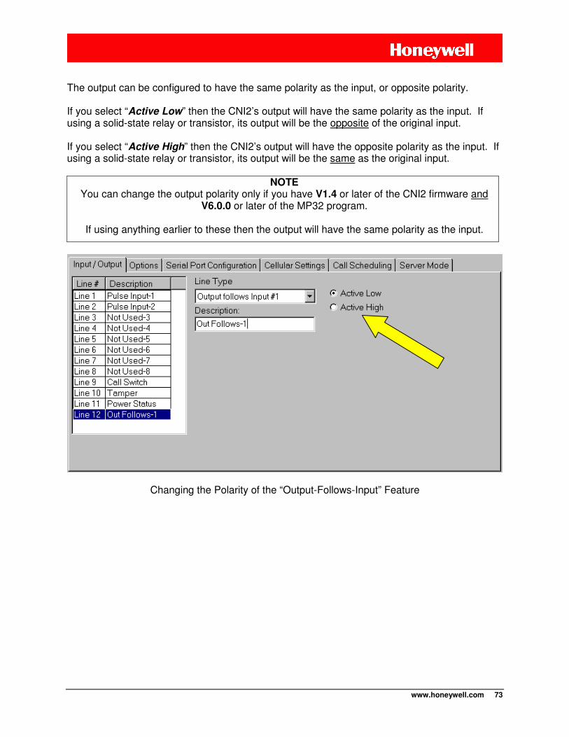
www.honeywell.com 73
The output can be configured to have the same polarity as the input, or opposite polarity. If you select “Active Low” then the CNI2’s output will have the same polarity as the input. If using a solid-state relay or transistor, its output will be the opposite of the original input. If you select “Active High” then the CNI2’s output will have the opposite polarity as the input. If using a solid-state relay or transistor, its output will be the same as the original input.
NOTE You can change the output polarity only if you have V1.4 or later of the CNI2 firmware and
V6.0.0 or later of the MP32 program.
If using anything earlier to these then the output will have the same polarity as the input.
Changing the Polarity of the “Output-Follows-Input” Feature
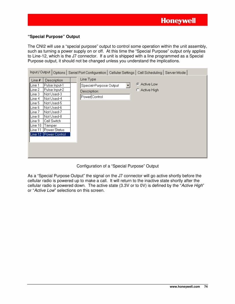
www.honeywell.com 74
“Special Purpose” Output
The CNI2 will use a “special purpose” output to control some operation within the unit assembly, such as turning a power supply on or off. At this time the “Special Purpose” output only applies to Line-12, which is the J7 connector. If a unit is shipped with a line programmed as a Special Purpose output, it should not be changed unless you understand the implications.
Configuration of a “Special Purpose” Output As a “Special Purpose Output” the signal on the J7 connector will go active shortly before the cellular radio is powered up to make a call. It will return to the inactive state shortly after the cellular radio is powered down. The active state (3.3V or to 0V) is defined by the “Active High” or “Active Low” selections on this screen.
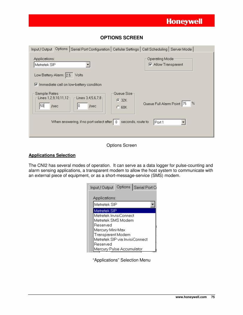
www.honeywell.com 75
OPTIONS SCREEN
Options Screen Applications Selection
The CNI2 has several modes of operation. It can serve as a data logger for pulse-counting and alarm sensing applications, a transparent modem to allow the host system to communicate with an external piece of equipment, or as a short-message-service (SMS) modem.
“Applications” Selection Menu
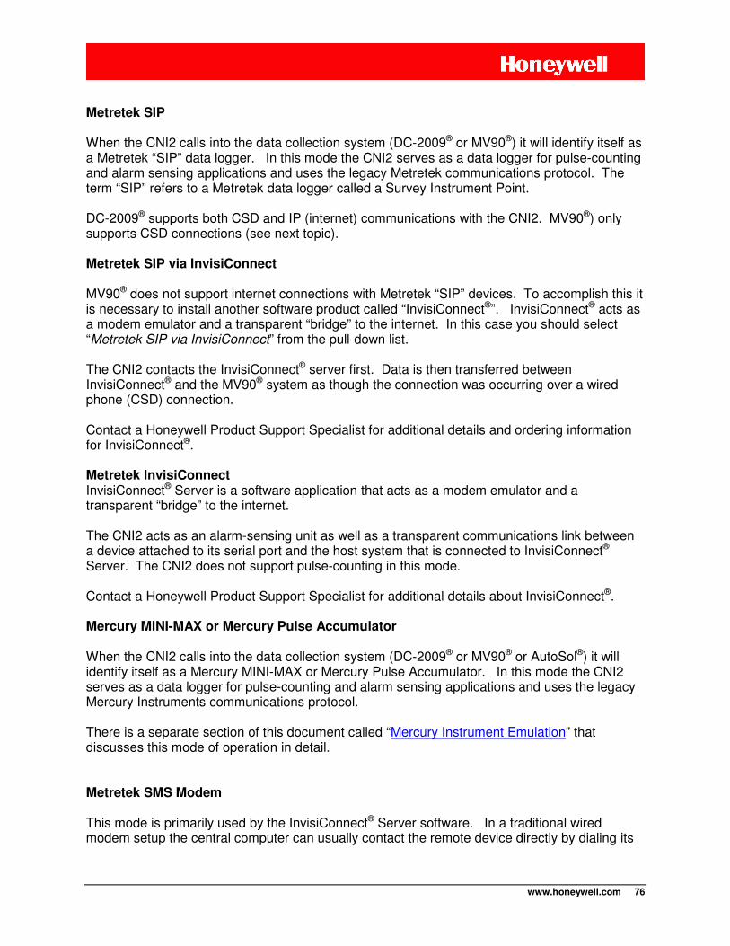
www.honeywell.com 76
Metretek SIP When the CNI2 calls into the data collection system (DC-2009® or MV90®) it will identify itself as a Metretek “SIP” data logger. In this mode the CNI2 serves as a data logger for pulse-counting and alarm sensing applications and uses the legacy Metretek communications protocol. The term “SIP” refers to a Metretek data logger called a Survey Instrument Point. DC-2009® supports both CSD and IP (internet) communications with the CNI2. MV90®) only supports CSD connections (see next topic). Metretek SIP via InvisiConnect MV90® does not support internet connections with Metretek “SIP” devices. To accomplish this it is necessary to install another software product called “InvisiConnect®”. InvisiConnect® acts as a modem emulator and a transparent “bridge” to the internet. In this case you should select “Metretek SIP via InvisiConnect” from the pull-down list. The CNI2 contacts the InvisiConnect® server first. Data is then transferred between InvisiConnect® and the MV90® system as though the connection was occurring over a wired phone (CSD) connection. Contact a Honeywell Product Support Specialist for additional details and ordering information for InvisiConnect®.
Metretek InvisiConnect InvisiConnect® Server is a software application that acts as a modem emulator and a transparent “bridge” to the internet. The CNI2 acts as an alarm-sensing unit as well as a transparent communications link between a device attached to its serial port and the host system that is connected to InvisiConnect® Server. The CNI2 does not support pulse-counting in this mode. Contact a Honeywell Product Support Specialist for additional details about InvisiConnect®.
Mercury MINI-MAX or Mercury Pulse Accumulator
When the CNI2 calls into the data collection system (DC-2009® or MV90® or AutoSol®) it will identify itself as a Mercury MINI-MAX or Mercury Pulse Accumulator. In this mode the CNI2 serves as a data logger for pulse-counting and alarm sensing applications and uses the legacy Mercury Instruments communications protocol. There is a separate section of this document called “Mercury Instrument Emulation” that discusses this mode of operation in detail. Metretek SMS Modem This mode is primarily used by the InvisiConnect® Server software. In a traditional wired modem setup the central computer can usually contact the remote device directly by dialing its
www.honeywell.com 77
phone number. On the Internet there are “servers” and “clients”. A server is usually a computer system that is always running and always “listening” for connection requests from clients. When you use your personal computer to access a website your PC is the client and the website is the server. A client cannot be contacted directly via the Internet. In many cases the CNI2 acts as a client only. However the CNI2 can be “paged”. The page then causes the CNI2 to call back immediately to the central office. One method of paging is by Short Message Service, or SMS. SMS is often used to send short text messages between two cellular phones. In some cases a message can be sent from a computer using a traditional SMTP (email) server. But there may be obstacles to sending an SMS. First, the computer running the data collection system may not have access to an SMTP server. Or if the computer is using a cellular modem to connect to the Internet it may not be able to send SMS messages without first terminating the Internet connection. Finally, for security reasons, some cellular providers only allow SMS messages to be exchanged between two mobile devices, and not between a mobile device and an SMTP server. The SMS Modem is a special configuration of a CNI2. Its sole purpose is to allow the central computer to send mobile-to-mobile SMS messages via the cellular network without interfering with existing Internet connections or requiring an email server connection. Transparent Modem In this mode the CNI2 serves as a communications device only and does not count pulses or report alarms. It establishes a two-way connection between the central office and any serial device connected to one of its serial ports. As a transparent modem a call can be triggered by an alarm event (CALL switch, TAMPER switch, etc.). However since it is not calling a known data collection system such as DC-2009® or MV90® it has no way to report the actual reason for the call. Allow Transparent Mode
This checkbox only applies when the CNI2 is configured as a Metretek SIP, a Mercury MINI-MAX or Mercury Pulse Accumulator. At the beginning of a call the CNI2 will attempt to communicate with the data collection system using the Metretek or Mercury protocol. If after a short period of time there is no recognizable response from the system, and if the “Allow Transparent” box is checked, the CNI2 will establish a transparent communications link between the device attached to its serial port and the host system. Here’s an example of how this might be used. Let’s say the CNI2 is counting pulses from its UMB index and its serial port is connected to a digital camera. The CNI2 will normally call into DC-2009® or MV90® to report its UMB count information. The data collection system does not know that there is a camera at the site and wouldn’t know how to communicate with it anyway.
www.honeywell.com 78
Now another application program (not DC-2009® or MV90® or AutoSol®) wants to capture an image of the site where the CNI2 is located. After the CNI2 connects and does not receive a recognizable Metretek or Mercury response it will establish a connection to the camera. At this point the application program can now communicate directly with the camera and will close the connection when finished. The time it takes to establish the transparent connection depends on the way the CNI2 is configured. As a Metretek SIP this could be as short as 5 – 10 seconds. As a Mercury MINI-MAX or Pulse Accumulator this might be a long as 50 seconds or more. There is a separate section of this document called “Mercury Instrument Emulation” that discusses the reasons for this and ways to shorten the time. On the Cellular Settings configuration screen (to be discussed shortly) is a setting called “Session Timeout”. During transparent mode if there is no communications between the host system and the serial device for this period of time, the CNI2 will terminate the connection by itself. This period of time has a direct impact on battery life and should be kept as short as is reasonable for the application. Also see the next discussion about port selection as this also affects the transparent mode of operation. When Answering if No Port Select……. This setting is used when the CNI2 is allowed to enter “transparent” mode. In this mode the CNI2 will establish a transparent communications link between the host system and the device attached to one of its serial ports (see previous discussions). This mode is only possible if (a) the CNI2 has been configured as a “Transparent Modem” or (b) the CNI2 is configured as a Metretek or Mercury data logger and the “Allow Transparent” box is checked. The CNI2 has one on-board serial port (Port-1). This can be expanded to two ports using the Serial Port Multiplexer discussed earlier in this document. Future options will allow up to 7 additional ports to be added. Each port is assigned a unique ID number using the Serial Port Configuration screen, to be discussed shortly. Port-1 is automatically assigned the RUID that is assigned to the entire CNI2. Port-2 and beyond are assigned unique ID numbers by you. When the CNI2 receives an incoming connection request, or is paged to call back to the central office, it needs to know which serial port to select for the call. Once the connection with the host is established the CNI2 will wait a certain number of seconds (defined by you) for a special command to arrive from the host. This command has the format:
+-+PAxxxxxx<cr>
where “xxxxxx” is the ID of one of the serial ports and <cr> is a carriage return character. The “xxxxxx” must contain all six digits of the RUID including leading 0’s.
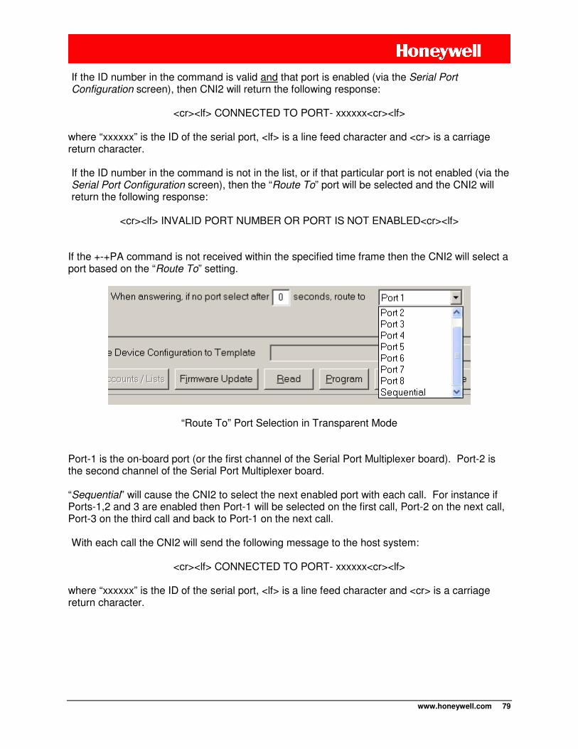
www.honeywell.com 79
If the ID number in the command is valid and that port is enabled (via the Serial Port Configuration screen), then CNI2 will return the following response:
<cr><lf> CONNECTED TO PORT- xxxxxx<cr><lf>
where “xxxxxx” is the ID of the serial port, <lf> is a line feed character and <cr> is a carriage return character. If the ID number in the command is not in the list, or if that particular port is not enabled (via the Serial Port Configuration screen), then the “Route To” port will be selected and the CNI2 will return the following response:
<cr><lf> INVALID PORT NUMBER OR PORT IS NOT ENABLED<cr><lf>
If the +-+PA command is not received within the specified time frame then the CNI2 will select a port based on the “Route To” setting.
“Route To” Port Selection in Transparent Mode Port-1 is the on-board port (or the first channel of the Serial Port Multiplexer board). Port-2 is the second channel of the Serial Port Multiplexer board. “Sequential” will cause the CNI2 to select the next enabled port with each call. For instance if Ports-1,2 and 3 are enabled then Port-1 will be selected on the first call, Port-2 on the next call, Port-3 on the third call and back to Port-1 on the next call. With each call the CNI2 will send the following message to the host system:
<cr><lf> CONNECTED TO PORT- xxxxxx<cr><lf>
where “xxxxxx” is the ID of the serial port, <lf> is a line feed character and <cr> is a carriage return character.
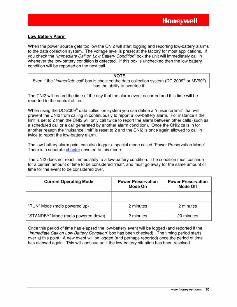
www.honeywell.com 80
Low Battery Alarm When the power source gets too low the CNI2 will start logging and reporting low-battery alarms to the data collection system. The voltage level is preset at the factory for most applications. If you check the “Immediate Call on Low Battery Condition” box the unit will immediately call in whenever the low-battery condition is detected. If this box is unchecked then the low battery condition will be reported on the next call.
NOTE Even if the “immediate call” box is checked the data collection system (DC-2009® or MV90®)
has the ability to override it. The CNI2 will record the time of the day that the alarm event occurred and this time will be reported to the central office. When using the DC-2009® data collection system you can define a “nuisance limit” that will prevent the CNI2 from calling in continuously to report a low-battery alarm. For instance if the limit is set to 2 then the CNI2 will only call twice to report the alarm between other calls (such as a scheduled call or a call generated by another alarm condition). Once the CNI2 calls in for another reason the “nuisance limit” is reset to 2 and the CNI2 is once again allowed to call in twice to report the low-battery alarm. The low-battery alarm point can also trigger a special mode called “Power Preservation Mode”. There is a separate chapter devoted to this mode. The CNI2 does not react immediately to a low-battery condition. The condition must continue for a certain amount of time to be considered “real”, and must go away for the same amount of time for the event to be considered over.
Current Operating Mode Power Preservation Mode On
Power Preservation Mode Off
“RUN” Mode (radio powered up) 2 minutes 2 minutes
“STANDBY” Mode (radio powered down) 2 minutes 20 minutes
Once this period of time has elapsed the low-battery event will be logged (and reported if the “Immediate Call on Low Battery Condition” box has been checked). The timing period starts over at this point. A new event will be logged (and perhaps reported) once the period of time has elapsed again. This will continue until the low-battery situation has been resolved.
www.honeywell.com 81
Queue Size
The CNI2 can count electrical pulses from up to siz sources although the data collection system (DC-2009® or MV90®) will only accept up to 4. Pulses are counted over a specific time interval and the total for that period is saved as one record. It then starts the counting process over for the next time interval and this process continues indefinitely. The place where this is stored is called the “queue”. The time interval can be anything evenly divisible into 60 minutes. A shorter time period allows you to observe small changes with more detail. But it also consumes memory more quickly, causing the CNI2 to need to communicate with the data collection system more frequently so that older data is not lost. This can have an impact on both battery life and the cost of the cellular service. The CNI2 can save a total of 30,000 records before it starts to overwrite the oldest records. These are divided equally between all active pulse-counting channels. If only one channel is used for pulse-counting then all 30,000 record locations will be used for that channel. If using a 10-minute interval it would take a little over 200 days to reach the end of the memory. If three channels are active then each channel is allocated 1/3 of the memory, or 10,000 records. Each record consumes 2 bytes of memory. For a queue size of 30,000 records select the “60K” size. For a smaller queue (16,000 records) select the “32K” size. The data collection system (DC-2009® or MV90®) has the ability to request the entire contents of the queue, so a smaller queue size will result in a shorter call, lower power consumption and lower cellular costs. Queue Full Alarm
To prevent the loss of accumulated data the CNI2 will place an immediate call to the central office when the storage “queue” reaches a certain point. You can define this as any percentage between 1% and 100%. Default is 75%. Sample Rates
The CNI2 does not inspect the state of the inputs 100% of the time; otherwise it wouldn’t have time to perform any other functions. Rather the CNI2 briefly inspects (“samples”) the condition of the lines one or more times each second. You can configure the CNI2 to take as few as one sample per second or as many as 50 samples per second. The 12 possible input/output lines are divided into two groups, each with its own sampling rate. Lines-1, 2, 9, 10, 11 and 12 are one group. Lines-3 thru 8 are in the other group.
NOTE Lines #3 thru #8 are only available using an optional expansion board which is not available
at this time. The sample rate is based on how quickly you expect the inputs to change. Faster sampling rates are used for quickly-changing inputs but results in higher power consumption. Too slow of a sampling rate can lead to errors. Debouncing and sample rates are discussed in more detail later in this document.
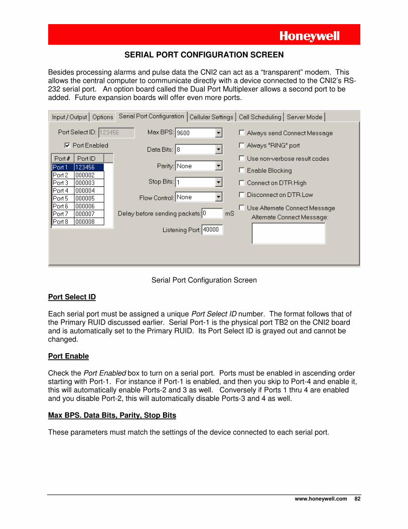
www.honeywell.com 82
SERIAL PORT CONFIGURATION SCREEN
Besides processing alarms and pulse data the CNI2 can act as a “transparent” modem. This allows the central computer to communicate directly with a device connected to the CNI2’s RS-232 serial port. An option board called the Dual Port Multiplexer allows a second port to be added. Future expansion boards will offer even more ports.
Serial Port Configuration Screen
Port Select ID Each serial port must be assigned a unique Port Select ID number. The format follows that of the Primary RUID discussed earlier. Serial Port-1 is the physical port TB2 on the CNI2 board and is automatically set to the Primary RUID. Its Port Select ID is grayed out and cannot be changed. Port Enable Check the Port Enabled box to turn on a serial port. Ports must be enabled in ascending order starting with Port-1. For instance if Port-1 is enabled, and then you skip to Port-4 and enable it, this will automatically enable Ports-2 and 3 as well. Conversely if Ports 1 thru 4 are enabled and you disable Port-2, this will automatically disable Ports-3 and 4 as well. Max BPS. Data Bits, Parity, Stop Bits
These parameters must match the settings of the device connected to each serial port.
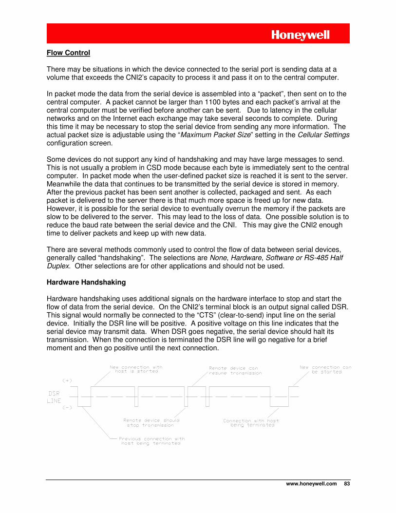
www.honeywell.com 83
Flow Control
There may be situations in which the device connected to the serial port is sending data at a volume that exceeds the CNI2’s capacity to process it and pass it on to the central computer. In packet mode the data from the serial device is assembled into a “packet”, then sent on to the central computer. A packet cannot be larger than 1100 bytes and each packet’s arrival at the central computer must be verified before another can be sent. Due to latency in the cellular networks and on the Internet each exchange may take several seconds to complete. During this time it may be necessary to stop the serial device from sending any more information. The actual packet size is adjustable using the “Maximum Packet Size” setting in the Cellular Settings configuration screen. Some devices do not support any kind of handshaking and may have large messages to send. This is not usually a problem in CSD mode because each byte is immediately sent to the central computer. In packet mode when the user-defined packet size is reached it is sent to the server. Meanwhile the data that continues to be transmitted by the serial device is stored in memory. After the previous packet has been sent another is collected, packaged and sent. As each packet is delivered to the server there is that much more space is freed up for new data. However, it is possible for the serial device to eventually overrun the memory if the packets are slow to be delivered to the server. This may lead to the loss of data. One possible solution is to reduce the baud rate between the serial device and the CNI. This may give the CNI2 enough time to deliver packets and keep up with new data. There are several methods commonly used to control the flow of data between serial devices, generally called “handshaking”. The selections are None, Hardware, Software or RS-485 Half Duplex. Other selections are for other applications and should not be used.
Hardware Handshaking
Hardware handshaking uses additional signals on the hardware interface to stop and start the flow of data from the serial device. On the CNI2’s terminal block is an output signal called DSR. This signal would normally be connected to the “CTS” (clear-to-send) input line on the serial device. Initially the DSR line will be positive. A positive voltage on this line indicates that the serial device may transmit data. When DSR goes negative, the serial device should halt its transmission. When the connection is terminated the DSR line will go negative for a brief moment and then go positive until the next connection.
www.honeywell.com 84
Hardware Flow Control
Software Handshaking
Xon/Xoff handshaking (also called “software handshaking”) uses two ASCII characters to stop and start the flow. The CNI2 will send an “Xoff” (19 decimal or 13 hex) to the serial device to stop the transmission, and an “Xon” (17 decimal or 11 hex) to resume transmission. Once an Xoff character is sent the serial device should halt its transmission. Also the DSR line will remain positive throughout the session. When the connection is terminated the DSR line will go negative for a brief moment and then go positive until the next connection.
No (None) Handshaking
If NONE is selected the DSR line will remain positive throughout the session. When the connection is terminated the DSR line will go negative for a brief moment and then go positive until the next connection. In CSD mode each byte of data from the serial device is immediately passed on to the central computer, and visa versa. In this case flow control is generally not needed and “NONE” can be selected as the flow control method. In packet mode if the serial device never sends more than 1100 bytes in one message and must receive a response before sending another message, then the flow control can be set to “NONE”. RS-485 Half Duplex
Select this only if an external RS485 conversion module is being used in half-duplex mode.
Delay before Sending Packets
In packet mode the data from the serial device is assembled into “packets” and sent on to the central computer. The maximum size of the packet is programmable and cannot exceed 1100 bytes. The data from the serial device is sent out whenever it exceeds the maximum packet size. However some or all messages from the serial device may never exceed the maximum packet size. Therefore the CNI2 must have a way to determine when the serial device’s message is complete and ready to send to the host. Some serial devices may terminate a message with a particular character like a carriage return or line feed. However for other devices these two characters may be meaningful data. Therefore searching for a particular terminating character may not work in all cases. The CNI2 determines when a message is complete when there have been no characters received from the serial device for a certain period of time. This value can range from 1 to 65535 milliseconds and may have to be determined experimentally. A value that is too low may cause a message to be sent is several packets. Also, each packet contains the device’s message along with some overhead information used for routing and error checking. Breaking a larger message down into several packets means more overhead and could affect the cost of the cellular service. Remember, the cost of packet service is usually based on the number of bytes exchanged in a month.
www.honeywell.com 85
Choosing a value that is too high may cause the application program running on the central computer to abort or retry too often because it did not receive a response within an acceptable period of time. Start with a value of 50 ms and fine-tune it from there.
Listening Port
The CNI2 can act as an internet server and accept connection requests from other clients. This is discussed in detail in the section of this document called Server Mode. In order to connect to the CNI2 the client must know the CNI2’s IP address and port number. The CNI2 has its own “listening” port number which appears on the Server Mode Screen. Each serial port has a listening port number as well. Starting with firmware version V1.4 this allows the client to establish a connection to a device attached to the serial port rather than to the CNI2 itself. See Connections to a Specific Serial Port for more details about this.
NOTE Do not use a Listening Port number of 0 (zero).
Always Send CONNECT Message
The serial device connected to the CNI2 can request a call or answer an incoming call by issuing specific “AT” commands such as “ATD” (dial) or “ATA” (answer). When the connection with the central computer has been established the CNI2 will send a “CONNECT” message to the serial device to let it know that the connection has been established. The CNI2 can also place a call on its own in response to an alarm condition or some other event. In these situations the CNI2 would not normally send a “CONNECT” message to the serial device. However some devices may require a “CONNECT” message before allowing further communications. By checking the Always Send Connect Message box the CNI2 will always send a “CONNECT” message every time it connects with the central computer, regardless of who originated the call.
. Always “RING” Port
In some applications the serial device connected to the CNI2 may have been programmed to automatically answer incoming calls. After the call is answered and a connection is established with the central computer a “CONNECT” message is usually sent to the serial device. In other applications the serial device might control when incoming calls will be answered. The CNI2 will send a number of “RING” messages to the serial device and wait for the serial device to respond with an answer (“ATA”) command. If this mode is required, check the Always “RING” Port checkbox. The CNI2 will send up to three “RING” messages to the remote device. If an “ATA” is received the CNI2 will respond with a “CONNECT” message. If no response is received the CNI2 will send a “CONNECT” message only if the Always Send Connect Message box has been checked.
www.honeywell.com 86
Use Non-verbose Result Codes For AT-compatible modems a “verbose” message is usually a readable text string such as “CONNECT” or “RING”. A “terse”, “numeric”, or “non-verbose” message typically consists of one or two numeric digits, such as “2”. The CNI2 defaults to verbose messages, but the remote device can change this by issuing an “ATV” or “ATV0” command. However some devices may simply expect non-verbose messages and will not issue any additional commands to make this happen. In this case check the Use Non-verbose Result Codes box.
Enable Blocking
This is used solely for InvisiConnect® applications and is not currently supported.
Use Alternate CONNECT Message
Usually the serial device requires some sort of notification when a connection has been established with the central computer. Often this message will be “CONNECT xxxx”, where “xxxx” indicates the baud rate, such as “CONNECT 9600”. The CNI2 defaults to this format, but the serial device can change this to a simple “CONNECT” message by issuing an “ATX” command. However some serial devices may simply expect a simple “CONNECT” message and will not issue any additional commands to make this happen. In this case check the Edit CONNECT Message box. You must specify the exact message in the Connect Message window. This includes non-readable (control) characters. Non-verbose responses are often one to two ASCII numbers followed by a carriage return character. Verbose messages are normally preceded and followed by a carriage return and line feed combination. Use the “Enter” key on your keyboard to insert a carriage return and line feed combination. To insert a single line feed character press and hold the ALT key while on the keyboard’s numeric keypad enter the digits 0 1 0. Then release the ALT key. To insert a single carriage return character press and hold the ALT key while on the keyboard’s numeric keypad enter the digits 0 1 3. Then release the ALT key. In either case you will not actually see the characters in the window, but you may see the cursor move to the next line.
Connect on DTR High Some serial devices may indicate a desire to place a call by simply activating a control line. On the CNI2’s TB2 terminal block is an input line called DTR. If the DTR input line on the communications terminal block goes positive, the CNI2 will wait 10 seconds for an “ATD” (dial) or “ATA” (answer) command from the device. If a command is received the CNI2 will start the call process. Otherwise a call will be placed after 10 seconds and the CNI2 will behave according to the Always Send Connect Message setting. If enabled a “CONNECT” message will be sent to the serial device once the connection with the central computer has been established. The call will end with a “NO CARRIER” message. If the connection cannot be established a “NO CARRIER” message is returned. As discussed earlier two remote devices can be wired to the same CNI2 using the optional Serial Port Multiplexer board. Either remote device can raise the DTR line but the CNI2 will not be able to determine which device is actually asserting the line. If the wrong port is selected when this happens the CNI2 may not see the “ATD” command if the remote device issues one.
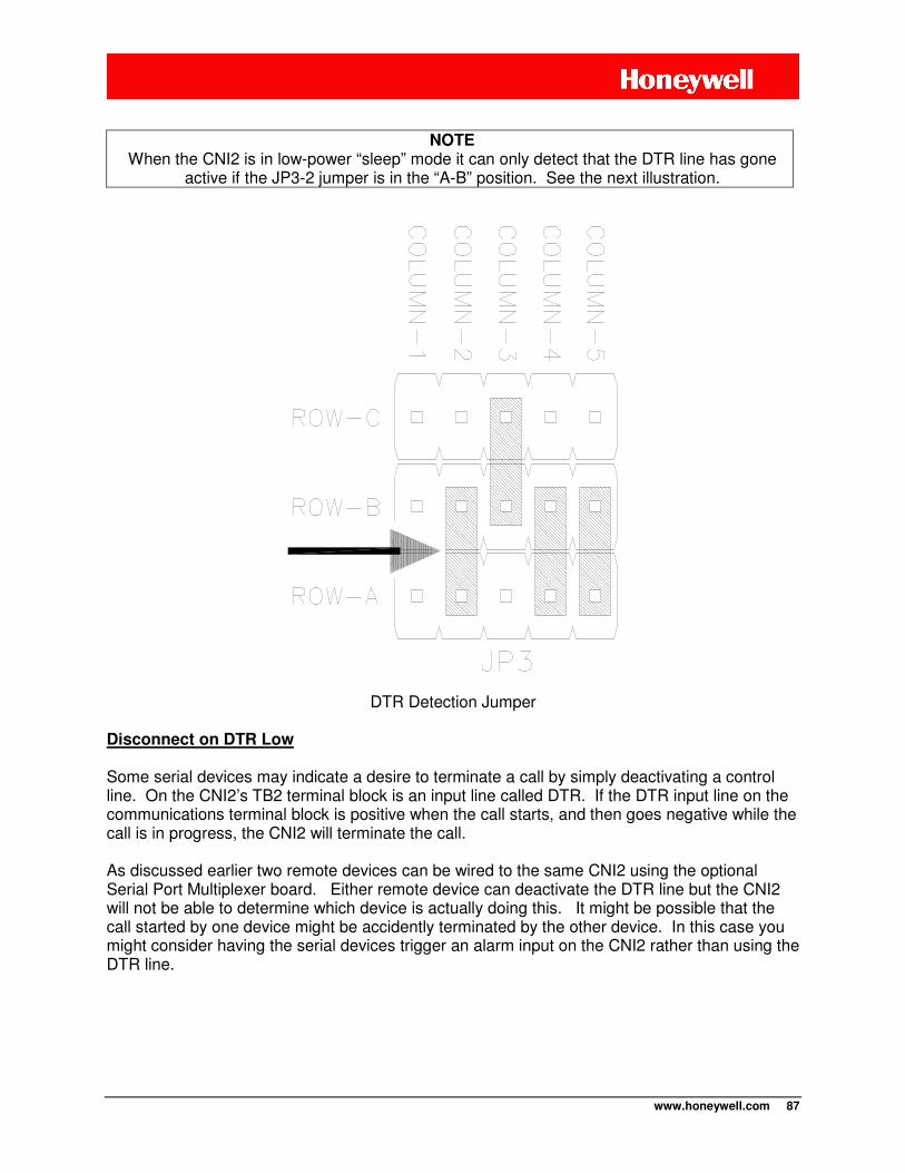
www.honeywell.com 87
NOTE
When the CNI2 is in low-power “sleep” mode it can only detect that the DTR line has gone active if the JP3-2 jumper is in the “A-B” position. See the next illustration.
DTR Detection Jumper Disconnect on DTR Low Some serial devices may indicate a desire to terminate a call by simply deactivating a control line. On the CNI2’s TB2 terminal block is an input line called DTR. If the DTR input line on the communications terminal block is positive when the call starts, and then goes negative while the call is in progress, the CNI2 will terminate the call. As discussed earlier two remote devices can be wired to the same CNI2 using the optional Serial Port Multiplexer board. Either remote device can deactivate the DTR line but the CNI2 will not be able to determine which device is actually doing this. It might be possible that the call started by one device might be accidently terminated by the other device. In this case you might consider having the serial devices trigger an alarm input on the CNI2 rather than using the DTR line.
www.honeywell.com 88
CELLULAR SETTINGS SCREEN
“SIP” Versus “MIP”
If the CNI2 will be communicating over the Internet there are two protocols that can be used. The original protocol used in the early days of dial-up and wireless Internet service is called Simple Internet Protocol, or “SIP”. Most wireless carriers still support SIP. The more-recent Mobile Internet Protocol, or “MIP”, solves the problems of losing an internet connection as you travel from cell to cell, or if your call is passed on to a different roaming partner. The CNI2 will likely be in a fixed location and therefore doesn’t require MIP. However there are now certain cellular providers that have dropped support for SIP in favor of MIP. You have the ability to choose which protocol to use. Check with your service provider if in doubt.
NOTE If you have a choice between using SIP and MIP, SIP is generally faster, resulting in
shorter calls. “Dynamic” Versus “Static” IP Addresses Each time the CNI2 requests an internet connection from the cellular provider it is assigned an IP (Internet Protocol) Address. You can request a “Static” IP address for each CNI2. This means that the CNI2 is assigned the same address with each connection and no other device in the world will have that same address. You may have to pay more to have a Static IP address. If you do not request a Static IP address then the CNI2 will likely be assigned a new address each time it connects. This is known as a “Dynamic” IP address. This address is only valid for the current connection and will likely be assigned to another device after the current connection is terminated. If you intend to allow the CNI2 to act as a Server then it must have a Static IP address. Server Mode is discussed later in this document. In order for some other machine to contact the CNI2 that machine must know the IP address of the CNI2. This is why it is important for the IP address to remain constant. Otherwise if the CNI2 will only call in to a server such as DC-2009® and InvisiConnect® then a Static IP address is not a requirement.
www.honeywell.com 89
CDMA Service (Aeris, Verizon, Sprint)
CDMA is an abbreviation for Code Division Multiple Access communications. CDMA technology was originally developed for military applications but was eventually commercialized. This communications standard is widely used in North America and in some parts of Asia and South America. Rather than dividing calls into time slots like GSM, CDMA allows all users to transmit at the same time. Each call is accompanied by a unique digital code that allows it to be differentiated from the rest. As an analogy suppose you are in a crowded room and many conversations are taking place at the same time. Your brain is able to distinguish the conversation you are having with your friend because it is able to focus on your friend’s voice characteristics. As the room grows more crowded each person must talk louder and the size of the conversation “zone” grows smaller. You may have to move closer to your friend to keep the conversation going. Thus the number of conversations is limited by the overall interference and noise in the room. A cellular account must be activated with a cellular service provider prior to placing a CNI2 into service. The service provider may ask the device type, which must be specified as the “CNI2 / CDMA24”. CDMA Packet (Internet) Service
Single carrier, radio transmission technology (1X or 1XRTT) packet service may have to be added to a standard voice plan, or may be a stand-alone service. Packet service packages are generally priced by the number of bytes to be transferred rather than by the minute. Typically the smallest available package will be 1 megabyte (1 Mb) per month. The amount of data that the CNI2 will produce depends upon what sort of data is requested from the CNI2. The amount of information exchanged on each call may range from several hundred bytes to 10’s of thousands of bytes. It may be necessary to test the system for several months and then adjust the cellular account for the best cost based on your needs. The CNI2 requires full Internet access because the data collection software could be running on any server located anywhere in the world. Full access is usually assigned to customers who will be connecting a cellular modem to a personal computer. If you are allowed to use Simple Internet Protocol (SIP) one parameter that will be needed is the packet service connection command. In most cases the command will be ATD#777 but you may want to check with your service provider. CDMA Circuit Switched Data (CSD) Service
The service provider must support asynchronous circuit-switched data (CSD) exchange at the baud rate of the central computer’s modem. Sometimes this capability may be included as part of a standard voice package or it may be an add-on feature at extra cost. One consideration when ordering service is the frequency of calls to and from the CNI2. Each service provider offers different packages that may include a fixed number of minutes per month
www.honeywell.com 90
for a fixed price. However, when this number is exceeded, the cost per each additional minute can be very high. There are also variations in the way “minutes” are measured. For example, a call lasting 1 minute 10 seconds may be considered to be a 2-minute call by some providers. It might be possible to purchase less expensive packages that have additional “weekend” or “evening” minutes, and then schedule the CNI2 to call in at those times. Some plans may offer the 1st minute free. This might be advantageous for short calls. Another consideration when ordering service is the location of the CNI2 with respect to the service provider’s network. It is best to describe where the units will be located and where they will be calling, otherwise you could be charged “roaming” or long-distance fees. Some providers offer free long distance or no roaming charges as part of their basic plans. The final consideration is the direction of the calls. If the CNI2 is to originate calls, then the service must support “mobile-originate” service. If the unit is to receive calls, then “mobile-terminate” service is required. The service provider may need the following information:
• Type of cellular service desired, which is circuit-switched data (CSD). • The device type, which must be specified as the “CNI2 / CDMA24”. • Data rate. This rate must match the speed of central computer’s modem. • Mobile-originate and/or mobile-terminate service. • Number of minutes per month. • Location of the CNI2and the location of central computer (to determine if “roaming” or
long distance charges apply). • The service provider will need to know the “MEID” number printed on the radio. This is
printed on a label on the radio. Over-the-Air-Activation (OTAA) Unlike GSM, CDMA technology does not support the use of a SIM memory card (Subscriber Identity Module) to hold and transport account information. Therefore the account information must be downloaded into the cellular radio’s own memory. For some carriers this is accomplished by dialing a special phone number to request “over-the-air-activation” (OTAA). The activation phone number is specific to the service provider and must be programmed into the CNI2. The OTAA process does two things. After the first successful OTAA call a new phone number is programmed into the phone. This is the number that can be used to page the unit via a phone or data call, or via an SMS message. It also starts the account billing process. Second, a “preferred roaming list” (PRL) is downloaded into the phone. This instructs the radio which service provider(s) to search for and connect to. Over-the-air activation is attempted whenever the unit is reset. Another call will be attempted if the first one fails. After two unsuccessful attempts the CNI2 will go into an idle mode and will attempt another OTAA call every hour until one is successful. Until then the unit will not be able to call in to the data collection system. After the first successful call an OTAA call is then performed every 7 days. The reason for this is that cellular service providers often make arrangements with other providers to carry calls in
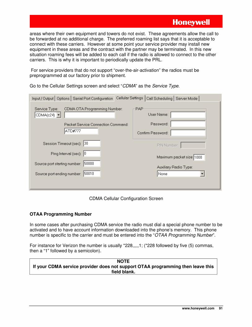
www.honeywell.com 91
areas where their own equipment and towers do not exist. These agreements allow the call to be forwarded at no additional charge. The preferred roaming list says that it is acceptable to connect with these carriers. However at some point your service provider may install new equipment in these areas and the contract with the partner may be terminated. In this new situation roaming fees will be added to each call if the radio is allowed to connect to the other carriers. This is why it is important to periodically update the PRL. For service providers that do not support “over-the-air-activation” the radios must be preprogrammed at our factory prior to shipment. Go to the Cellular Settings screen and select “CDMA” as the Service Type.
CDMA Cellular Configuration Screen
OTAA Programming Number
In some cases after purchasing CDMA service the radio must dial a special phone number to be activated and to have account information downloaded into the phone’s memory. This phone number is specific to the carrier and must be entered into the “OTAA Programming Number”. For instance for Verizon the number is usually *228,,,,,1; (*228 followed by five (5) commas, then a “1” followed by a semicolon).
NOTE If your CDMA service provider does not support OTAA programming then leave this
field blank.
www.honeywell.com 92
Packet Service Connection Command
This command is needed to request a Simple Internet Protocol (SIP) packet connection. For most CDMA service providers the phrase ATD#777 will work, and this is the default setting for the CNI2 in CDMA mode. If you are having problems connecting, this could be the problem. Contact your service provider for more information.
NOTE Leaving the Packet Service Connection Command field blank automatically selects If
Mobile Internet Protocol (MIP).
Session Timeout
If there is no communications between the CNI2 and the data collection system for this many seconds then the CNI2 will terminate the connection. Recommended value is 30 seconds. Ping Interval
Not used in this application. Source Port Starting / Ending Numbers
This only applies to packet (Internet) connections. DC-2009® and InvisiConnect® act as an Internet servers on your computer and thus must be allowed access to the outside world. Most corporate computer systems use firewall technology to prevent unauthorized and potentially damaging access from outside sources. To minimize potential invasion DC-2009® or InvisiConnect® and the CNI2 exchange private information using the 64-bit data encryption standard (DES64). If this exchange fails, the connection is terminated by both sides. When the CNI2 calls in it assigns itself what is known as a “source port” number. To further enhance security the CNI2 can be assigned only one or a specific range of source port numbers that the firewall will allow through. Valid source port numbers are 40000 – 65535. The CNI2 will use a new number with each call. For example for a range of 50000 – 50010, the first call will use 50000, the 2nd call 50001, and so on. When 50010 has been used the next port number will roll back to 50000. PAP User Name and Password
As an added security measure some cellular service providers require Password Authentication Protocol, or PAP, to gain access to their Internet service. The radio must present a user name and a password that was assigned when the cellular service was purchased. The user name or password can be any combination of printable characters, including spaces, such as “Bob Smith” or “1234”. The total number of characters for both the user name and password cannot exceed 48 characters. Often the cellular provider has a specific format for the username and password, so you will need to obtain that information from them.
www.honeywell.com 93
The password is hidden on this screen for added security. You must enter the password twice to verify that it was entered correctly.
NOTE If PAP is not required then both the user name and password fields
must be blank, otherwise the connection may be refused.
Maximum Packet Size
The setting has no affect in CSD mode. In packet (IP) mode the data from the serial device is assembled into “packets” and sent on to the central computer. The maximum packet size is 1100 bytes. Depending upon cellular network congestion and the quality of the radio connection, it may help to reduce the packet size. The larger the packet, the more chance there is for errors. Several smaller packets may have a better chance of arriving intact than a single large one. As each packet arrives at the central computer, it is checked for errors. If a packet arrives with errors, the computer will request retransmissions until it arrives intact or until a maximum number of retries have occurred. This can introduce significant delays and may increase the cost of the cellular service. Remember, the cost of packet service is based on the number of bytes exchanged in a month. Excessive retries may cause your maximum plan limit to be exceeded. If you notice excessive retries, or if the connection between the CNI2 and the central computer terminates early or often, this may be the cause. Auxiliary Radio Type
Not currently supported.
www.honeywell.com 94
GSM Service (AT&T, T-Mobile, Rogers)
GSM is an abbreviation for Global System for Mobile communications. This communications standard is widely used throughout Europe, Africa, Asia and parts of North and South America. Messages are digitized into packets and sent in brief bursts during allocated time slots using a variation of TDMA (Time Division Multiple Access) techniques. Up to 8 cellular phones can thus share the same frequency band, which in turn permits the system to support more users with existing equipment. Efficient utilization of spectrum is an important consideration for service providers since there is only a limited bandwidth space that has been allocated to cellular phone service. Most GSM systems throughout the world operate on either the 900 MHz or 1800 MHz communications bands. In North America most GSM systems operate on the 850 and 1900 MHz bands.
GSM Packet (Internet) Service
Some GSM service providers may not offer all forms of data transfer. General packet radio service (GPRS) may have to be added to a standard voice plan, or may be a stand-alone service. GPRS packages are generally priced by the number of bytes to be transferred rather than by the minute. Typically the smallest available package will be 1 megabyte (1 Mb) per month. The amount of data that the CNI2 will produce depends upon what sort of data is requested from it. The amount of information exchanged on each call may range from several hundred bytes to 10’s of thousands of bytes. It may be necessary to test the system for several months and then adjust the cellular account for the best cost based on your needs. In order to connect to the Internet, the cellular service provider has its own computer equipment called a “gateway” server, aptly named, as it is their gateway to the Internet. The server will have an “APN” (access point name), usually in the form of a domain name such as “internetaccess.providername.com” or something as simply as “proxy”. Contact your service provider for this information. This APN will be needed when configuring the CNI2. Service providers may have several different gateways to choose from, depending upon the type of service required. “Web phones” (cellular phones that support Internet access) are generally assigned to a gateway that only connects to WAP services (wireless application protocol). The CNI2 requires full Internet access because the data collection software could be running on any server located anywhere in the world. Full access gateways are usually assigned to customers who will be connecting a cellular modem to a personal computer. If you are allowed to use Simple Internet Protocol (SIP) another parameter that will be needed is the packet service connection command. In most cases the command will be ATD*99# but you may want to check with your service provider. A cellular account must be activated with a cellular service provider prior to placing a CNI2 into service. The service provider may ask the device type, which must be specified as the “CNI2 / GSM24”.
www.honeywell.com 95
GSM Circuit Switched Data (CSD) Service
For CSD service the GSM service provider must support asynchronous circuit-switched data (CSD) exchange at 4800 or 9600 baud. The baud rate must match the baud rate of the central computer’s modem. Sometimes this capability may be included as part of a standard voice package or it may be an add-on feature at extra cost. One consideration when ordering service is the frequency of calls to and from the CNI2. Each service provider offers different packages that may include a fixed number of minutes per month for a fixed price. However, when this number is exceeded, the cost per each additional minute can be very high. There are also variations in the way “minutes” are measured. For example, a call lasting 1 minute 10 seconds may be considered to be a 2-minute call by some providers. It might be possible to purchase less expensive packages that have additional “weekend” or “evening” minutes, and then schedule the CNI2 to call in at those times. Some plans may offer the 1st minute free. This might be advantageous for short calls. Another consideration when ordering service is the location of the CNI2 with respect to the service provider’s network. It is best to describe where the units will be located and where they will be calling, otherwise you could be charged “roaming” or long-distance fees. Some providers offer free long distance or no roaming charges as part of their basic plans. The final consideration is the direction of the calls. If the CNI2 is to originate calls, then the service must support “mobile-originate” service. If the unit is to receive calls, then “mobile-terminate” service is required. The service provider will need the following information:
• Type of cellular service desired, which is circuit-switched data (CSD). • The device type, which must be specified as the “CNI2 / GSM24”. • Data mode is to support 4800 or 9600-baud operation. This rate must match the speed
of central computer’s modem. • Mobile-originate and/or mobile-terminate service. • Number of minutes per month. • Location of the CNI2 and the location of central computer (to determine if “roaming” or
long distance charges apply). • The service provider may need to know the “IMEI” number printed on the radio.
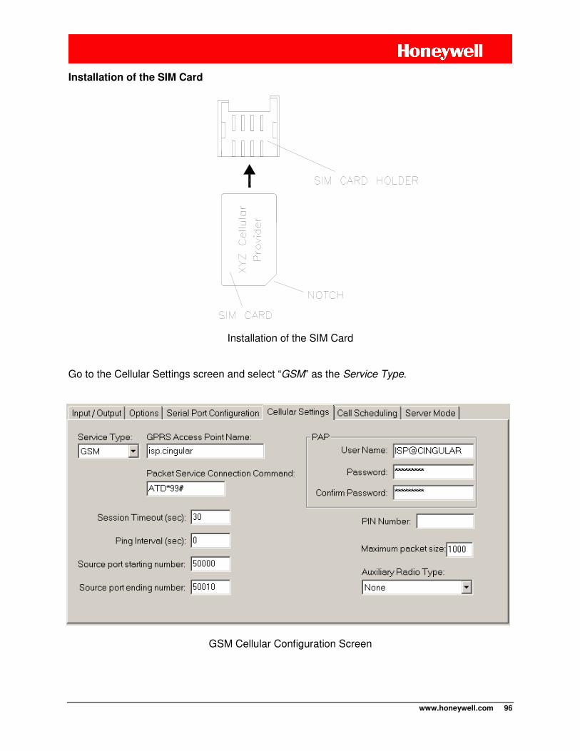
www.honeywell.com 96
Installation of the SIM Card
Installation of the SIM Card Go to the Cellular Settings screen and select “GSM” as the Service Type.
GSM Cellular Configuration Screen
www.honeywell.com 97
GPRS Access Point Name
If the CNI2 will be making an Internet connection the cellular service provider will need to provide an Internet APN (access point name). In order to connect to the Internet, the provider has its own computer equipment called a “gateway” server. The server will usually have an APN in the form of a domain name, such as “myserviceprovider.com” or a generic name such as “proxy”. Contact your service provider for this information. Packet Service Connection Command
This command is needed to request a Simple Internet Protocol (SIP) packet connection. For most GSM cellular service providers the phrase ATD*99# will work, and this is the default setting for the CNI2 in GSM mode. If you are having problems connecting, this could be the problem. Contact your service provider for more information.
NOTE Leaving the Packet Service Connection Command field blank automatically selects If
Mobile Internet Protocol (MIP).
Session Timeout
If there is no communications between the CNI2 and the data collection system for this many seconds then the CNI2 will terminate the connection. Recommended value is 30 seconds. Ping Interval
Not used in this application. Source Port Starting / Ending Numbers
This only applies to packet (Internet) connections. DC-2009® and InvisiConnect® act as an Internet servers on your computer and thus must be allowed access to the outside world. Most corporate computer systems use firewall technology to prevent unauthorized and potentially damaging access from outside sources. To minimize potential invasion DC-2009® or InvisiConnect® and the CNI2 exchange private information using the 64-bit data encryption standard. If this exchange fails, the connection is terminated by both sides. When the CNI2 calls in it assigns itself what is known as a “source port” number. To further enhance security the CNI2 can be assigned only one or a specific range of source port numbers that the firewall will allow through. Valid source port numbers are 40000 – 65535. The CNI2 will use a new number with each call. For example for a range of 50000 – 50010, the first call will use 50000, the 2nd call 50001, and so on. When 50010 has been used the next port number will roll back to 50000.
www.honeywell.com 98
PAP User Name and Password
As an added security measure some cellular service providers require Password Authentication Protocol, or PAP, to gain access to their Internet service. The radio must present a user name and a password that was assigned when the cellular service was purchased. The user name or password can be any combination of printable characters, including spaces, such as “Bob Smith” or “1234”. The total number of characters for both the user name and password cannot exceed 48 characters. Often the cellular provider has a specific format for the username and password, so you will need to obtain that information from them. The password is hidden on this screen for added security. You must enter the password twice to verify that it was entered correctly.
NOTE If PAP is not required then both the user name and password fields
must be blank, otherwise the connection may be refused.
PIN Number
GSM cellular radios require a memory card called a SIM card (Subscriber Identity Module). This is issued when the cellular service is purchased. A SIM holds information about the account so that certain services are made available to the customer such as Internet access. A SIM card can be moved to a different phone or radio, and the account information moves with it. Though convenient, this may encourage someone to steal the SIM card, insert it into his or her own cellular phone and make hundreds of hours of calls that will be billed to you or your company. A personal identification number (PIN) is an extra security measure to prevent unauthorized use of a SIM card. The PIN number can range from 1 to 8 numeric digits long and can be assigned by the cellular service provider when the card is activated.
NOTE If a PIN number is not required then the PIN number field must be blank.
Maximum Packet Size
The setting has no affect in CSD mode. In packet (IP) mode the data from the serial device is assembled into “packets” and sent on to the central computer. The maximum packet size is 1100 bytes. Depending upon cellular network congestion and the quality of the radio connection, it may help to reduce the packet size. The larger the packet, the more chance there is for errors. Several smaller packets may have a better chance of arriving intact than a single large one. As each packet arrives at the central computer, it is checked for errors. If a packet arrives with errors, the computer will request retransmissions until it arrives intact or until a maximum number of retries have occurred. This can introduce significant delays and may increase the cost of the cellular service. Remember, the cost of packet service is based on the number of bytes exchanged in a month. Excessive retries may cause your maximum plan limit to be exceeded.
www.honeywell.com 99
If you notice excessive retries, or if the connection between the CNI2 and the central computer terminates early or often, this may be the cause. Auxiliary Radio Type
Not currently supported. iDENService (Nextel, Harmony)
iDEN is an abbreviation for Integrated Digital Enhanced Network. This communications standard was developed by Motorola and provides its users the benefits of a trunked radio and a cellular telephone. Up to six communication channels share a 25 kHz space. iDEN operates on either the 800 MHz or 900MHz bands and is based on time division multiple access (TDMA) and GSM architectures. It supports circuit-switched data (CSD) and packet (Internet) communications, as well as voice and two-way radio services. Like GSM radios an iDEN radio requires a memory card called a SIM card (Subscriber Identity Module). When “iDEN” is selected as the Service Type most parameters are the same as for GSM. Refer to the previous section for information. One parameter that is not required is the Internet APN (access point name), so this field is disabled (grayed out). Set the Packet Service Connection Command to ATD. The CNI2 only supports internet (packet) mode when using the iDEN radio. CSD is not supported.
NOTE Motorola discontinued the io270 (iDEN) radio in 2010. Although the CNI2 is capable of working with this radio we may not be able to offer this configuration past 2010.
Customers that have their own supply of io270 radios should contact Honeywell.
www.honeywell.com 100
HSPA Service
NOTE
HSPA service is supported in V1.4 or later firmware. However at this time the CNI2 has not been approved to operate on HSPA networks
in North America. Contact Honeywell for updated information about this.
HSPA (High Speed Packet Access) is the 3rd generation (“3G”) deployment for many cellular providers. 3G was primarily intended to provide more services and faster speeds for handheld phones and other personal devices. The term “HSDPA” refers to enhanced download speeds (data being sent to the mobile device such as the CNI2). The term “HSUPA” refers to enhanced upload speeds (data being sent from the mobile device such as the CNI2). The cellular providers may offer higher speeds in one direction or the other, or the same speeds in both directions. The CNI2 does not require these types of services or speeds. However as the cellular technology advances the cellular providers may have to terminate “2G” services in order to provide more bandwidth for 3G devices. At the present time this would be the primary reason for requesting that the CNI2 support HSPA. If HSPA service is not available where the CNI2 is located, it will automatically switch over to standard GSM / GPRS (“2G”) service. Like GSM units, the HSPA version also requires a SIM card. All other programming aspects are the same as for a GSM unit.
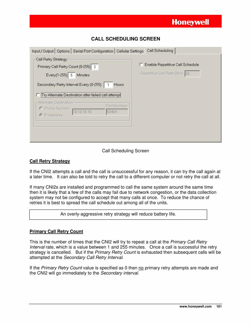
www.honeywell.com 101
CALL SCHEDULING SCREEN
Call Scheduling Screen
Call Retry Strategy
If the CNI2 attempts a call and the call is unsuccessful for any reason, it can try the call again at a later time. It can also be told to retry the call to a different computer or not retry the call at all. If many CNI2s are installed and programmed to call the same system around the same time then it is likely that a few of the calls may fail due to network congestion, or the data collection system may not be configured to accept that many calls at once. To reduce the chance of retries it is best to spread the call schedule out among all of the units.
Primary Call Retry Count
This is the number of times that the CNI2 will try to repeat a call at the Primary Call Retry Interval rate, which is a value between 1 and 255 minutes. Once a call is successful the retry strategy is cancelled. But if the Primary Retry Count is exhausted then subsequent calls will be attempted at the Secondary Call Retry Interval. If the Primary Retry Count value is specified as 0 then no primary retry attempts are made and the CNI2 will go immediately to the Secondary interval.
An overly-aggressive retry strategy will reduce battery life.
www.honeywell.com 102
Primary Call Retry Interval
This is the number of minutes to wait between each Primary retry attempt. The range is from 1 to 255 minutes. Secondary Call Retry Interval
After the Primary Call Retry Count has expired, or if it was set to 0 to begin with, the Secondary Call Retry Interval defines the number of hours between each additional attempt, up to 255 maximum. There is no limit to the number of times the CNI2 will attempt a call at this rate. Once a call is successful the retry strategy is cancelled. If the secondary interval is specified as 0 then no further attempts will be made to retry the call. Try Alternate Destination
The Try Alternate Destination feature applies only to a CNI2 configured as a “Metretek SIP”, “Metretek SIP via InvisiConnect”, “Mercury MINI-MAX” or “Mercury Pulse Accumulator”. If the CNI2 attempts a call and the call is unsuccessful for any reason, it can immediately retry the call to a different destination. If this 2nd call also fails then the CNI2 will follow the normal retry strategy described earlier. Each new retry will start with a call to the primary destination followed by a call to the alternate destination if the call to the primary destination fails. This feature is useful when there are several data collection systems sharing the same database and the primary system is overwhelmed with other calls or is down for maintenance or some other reason. Even if the retry strategy is disabled, if the Try Alternate Destination is checked, the CNI2 will still try one call to the alternate destination if the call to the primary destination fails. Enable Repetitive Call Schedule
In some applications you might want the CNI2 to call in at regular intervals. Check the box and enter the time period in minutes. This schedule will be followed as soon as the unit is reset or
To completely disable the retry strategy, set both the Primary Retry Count and the Secondary Retry Interval to zero (0).
Disabling the retry strategy is not recommended for most applications. Each time the CNI2 contacts DC-2009® or MV90® it is given a new time to call back. If a call fails and the unit is not allowed to retry the call, it will never receive a new call-back time and therefore will
not have a reason to call back again unless an alarm situation forces a new call.
If you do disable the retry strategy you may want to consider using the Repetitive Call Schedule feature. With this enabled the unit will have another reason to call in at a later
time.
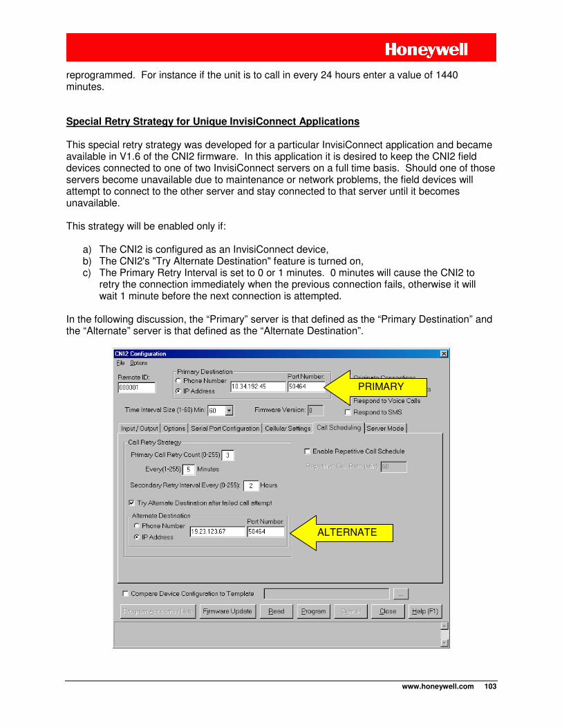
www.honeywell.com 103
reprogrammed. For instance if the unit is to call in every 24 hours enter a value of 1440 minutes.
Special Retry Strategy for Unique InvisiConnect Applications
This special retry strategy was developed for a particular InvisiConnect application and became available in V1.6 of the CNI2 firmware. In this application it is desired to keep the CNI2 field devices connected to one of two InvisiConnect servers on a full time basis. Should one of those servers become unavailable due to maintenance or network problems, the field devices will attempt to connect to the other server and stay connected to that server until it becomes unavailable. This strategy will be enabled only if:
a) The CNI2 is configured as an InvisiConnect device, b) The CNI2's "Try Alternate Destination" feature is turned on, c) The Primary Retry Interval is set to 0 or 1 minutes. 0 minutes will cause the CNI2 to
retry the connection immediately when the previous connection fails, otherwise it will wait 1 minute before the next connection is attempted.
In the following discussion, the “Primary” server is that defined as the “Primary Destination” and the “Alternate” server is that defined as the “Alternate Destination”.
PRIMARY
ALTERNATE
www.honeywell.com 104
The special retry strategy will do this:
a) If the CNI2 is able to connect to the Primary server, but loses the connection at some point, it will retry the next call to the Primary server again.
b) Only after the CNI2 is unable to connect to the Primary server three times in a row will it
attempt to connect to the Alternate server.
c) After connecting to the Alternate server, if it loses the connection, it will retry the next call to the Alternate server again.
d) Only after the CNI2 is unable to connect to the Alternate server three times in a row will
it attempt to connect to the Primary server.
e) If neither server is available then the CNI2 will alternately try each one three times (3 to Primary, 3 to Alternate, back to Primary, etc.). This will continue on forever or until one of the servers is contacted.
NOTE In this mode the Primary Retry Count is ignored and the CNI2 will never enter
Secondary Retry.
www.honeywell.com 105
SERVER MODE
“Servers” and “Clients”
On the Internet there are “servers” and “clients”. A server is a computer system that is always running and always “listening” for connection requests from clients. When you use your personal computer to access a website your PC is the client and the website’s comuter is the server. A client cannot be contacted directly via the Internet. For security and power-related reasons, the CNI2 usually acts as a client. If the CNI2 is configured as a data logger then the data collection system (such as DC-2009® or MV90®) is the server. There may be times when it is desired to contact the CNI2 rather than waiting for it to call in. There are several methods that can be used to “page” the CNI2. Paging is discussed in various other sections of this document. A “page” can be in the form of an SMS (text) message or the reception of a voice call. In either case the CNI2 will immediately call back to a server and is still acting as a client. The downside to this method is that the CNI2’s radio must remain powered up at all times to receive the page, and this mode requires a full-time power source rather than batteries. Another method is to allow the CNI2 can act as a server and accept connection requests from other clients. This still requires the radio to be powered up but the CNI2 can be scheduled to enter this mode for short periods of time to maximize battery life. If a full-time power source is used then the CNI2 can remain in Server Mode for as long as needed. Server Mode Requirements
Each time the CNI2 requests an internet connection from the cellular provider it is assigned an IP (Internet Protocol) Address. There are two types of IP Addresses; “static” and “dynamic”. Dynamic addresses are assigned from a pool of addresses and are only valid for the duration of a connection. The dynamic address assigned to the CNI2 for one session will likely be different for the next. In order for another client to contact the CNI2 that client must know the IP address of the CNI2. So it is important for the CNI2’s IP address to remain constant. If you wish to use Server Mode then you must request a “Static” IP address for the CNI2 when setting up the cellular service. This means that the CNI2 is assigned the same address with each connection and no other device will have that same address. You may have to pay more to have a Static IP address. Server Mode Security
Allowing any client to connect to the CNI2 has its risks, just as it would with your corporate or private servers. To provide some level of security there are several security features:
a) The CNI2 must be assigned a “port number”. When the client requests a connection to the CNI2 it must specify the CNI2’s static IP address and the port number in order for the connection to be allowed.
www.honeywell.com 106
b) When the client connects to the CNI2 the CNI2 will know the client’s IP address. You
can create a list of up to ten IP addresses, or range of IP addresses, that are allowed to connect to the CNI2. This is called a “Friends List”.
Server Mode Start / End Options
Generally the use of Server Mode requires a robust power source. To accommodate battery power sources we’ve provided several ways to start and end Server Mode to maximize battery life, as follows:
a) Server Mode can be scheduled to start and end at specific times during the day and on specific days of the week. The client system can then be configured to contact the CNI2 during those times.
b) Server Mode can be started when an external signal goes active and ended when that signal goes inactive.
c) Server Mode can be started when an external signal goes active and ended after a
user-defined period of time.
d) Server Mode can be started by receiving a special ATD command from a device connected to the CNI2’s serial port and ended after a user-defined period of time.
e) Server Mode can be ended after the 1st successful connection with a client.
Server Mode LED Indicators Here is the LED sequence from the time the CNI2 starts a Server session to the time it is ready for a connection request from a client. The green LED is mostly used to indicate the status of the radio and the network whereas the red LED indicates the progress of the connection.
1. If waking up from low-power “sleep” mode the green LED will start flashing once per second.
2. The radio is powered up and initialized for communications. If this is successful the
green LED’s flash rate will double.
3. When adequate signal is detected and the radio registers with the network the green LED’s flash rate will double again if the signal strength is less than 3 bars or will triple for signal strength of 3 bars or more.
4. The unit will start a connection sequence. While the green LED continues to flash the
red LED will begin flashing once per second.
5. When the unit has established a data connection with the network the red LED’s flash rate will double.
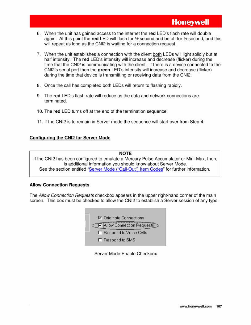
www.honeywell.com 107
6. When the unit has gained access to the internet the red LED’s flash rate will double again. At this point the red LED will flash for ½ second and be off for ½ second, and this will repeat as long as the CNI2 is waiting for a connection request.
7. When the unit establishes a connection with the client both LEDs will light solidly but at half intensity. The red LED’s intensity will increase and decrease (flicker) during the time that the CNI2 is communicating with the client. If there is a device connected to the CNI2’s serial port then the green LED’s intensity will increase and decrease (flicker) during the time that device is transmitting or receiving data from the CNI2.
8. Once the call has completed both LEDs will return to flashing rapidly.
9. The red LED’s flash rate will reduce as the data and network connections are
terminated.
10. The red LED turns off at the end of the termination sequence.
11. If the CNI2 is to remain in Server mode the sequence will start over from Step-4.
Configuring the CNI2 for Server Mode
NOTE If the CNI2 has been configured to emulate a Mercury Pulse Accumulator or Mini-Max, there
is additional information you should know about Server Mode. See the section entitled “Server Mode (“Call-Out”) Item Codes” for further information.
Allow Connection Requests
The Allow Connection Requests checkbox appears in the upper right-hand corner of the main screen. This box must be checked to allow the CNI2 to establish a Server session of any type.
Server Mode Enable Checkbox
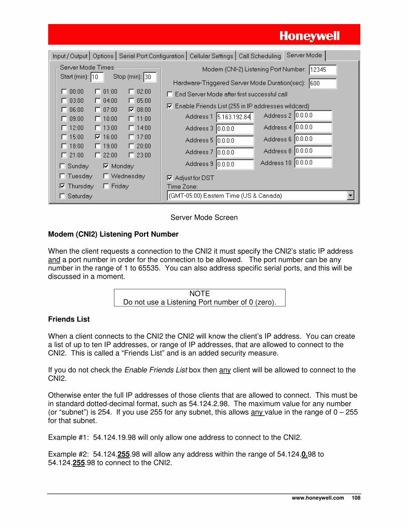
www.honeywell.com 108
Server Mode Screen Modem (CNI2) Listening Port Number
When the client requests a connection to the CNI2 it must specify the CNI2’s static IP address and a port number in order for the connection to be allowed. The port number can be any number in the range of 1 to 65535. You can also address specific serial ports, and this will be discussed in a moment.
NOTE Do not use a Listening Port number of 0 (zero).
Friends List
When a client connects to the CNI2 the CNI2 will know the client’s IP address. You can create a list of up to ten IP addresses, or range of IP addresses, that are allowed to connect to the CNI2. This is called a “Friends List” and is an added security measure. If you do not check the Enable Friends List box then any client will be allowed to connect to the CNI2. Otherwise enter the full IP addresses of those clients that are allowed to connect. This must be in standard dotted-decimal format, such as 54.124.2.98. The maximum value for any number (or “subnet”) is 254. If you use 255 for any subnet, this allows any value in the range of 0 – 255 for that subnet. Example #1: 54.124.19.98 will only allow one address to connect to the CNI2. Example #2: 54.124.255.98 will allow any address within the range of 54.124.0.98 to 54.124.255.98 to connect to the CNI2.
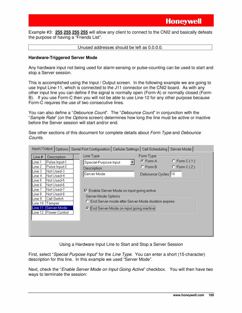
www.honeywell.com 109
Example #3: 255.255.255.255 will allow any client to connect to the CNI2 and basically defeats the purpose of having a “Friends List”.
Unused addresses should be left as 0.0.0.0.
Hardware-Triggered Server Mode
Any hardware input not being used for alarm-sensing or pulse-counting can be used to start and stop a Server session. This is accomplished using the Input / Output screen. In the following example we are going to use Input Line-11, which is connected to the J11 connector on the CNI2 board. As with any other input line you can define if the signal is normally open (Form-A) or normally closed (Form-B). If you use Form-C then you will not be able to use Line-12 for any other purpose because Form-C requires the use of two consecutive lines. You can also define a “Debounce Count”. The “Debounce Count” in conjunction with the “Sample Rate” (on the Options screen) determines how long the line must be active or inactive before the Server session will start and/or end. See other sections of this document for complete details about Form Type and Debounce Counts.
Using a Hardware Input Line to Start and Stop a Server Session First, select “Special Purpose Input” for the Line Type. You can enter a short (15-character) description for this line. In this example we used “Server Mode”. Next, check the “Enable Server Mode on Input Going Active” checkbox. You will then have two ways to terminate the session:
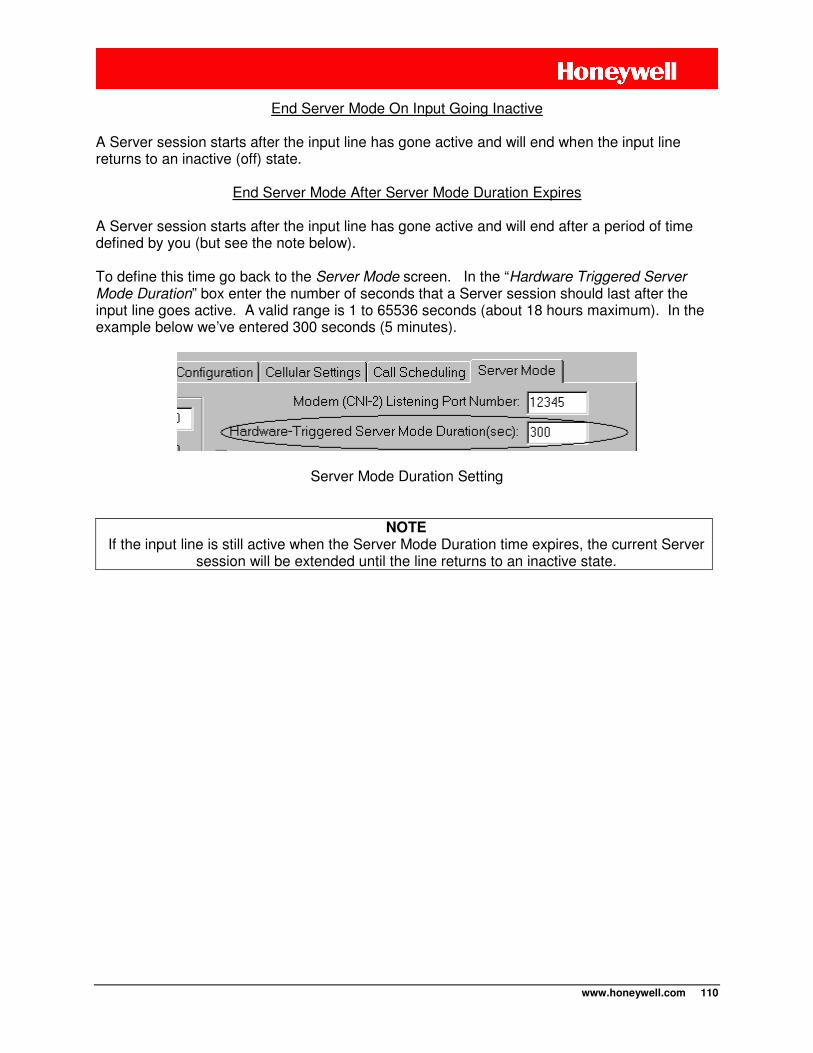
www.honeywell.com 110
End Server Mode On Input Going Inactive
A Server session starts after the input line has gone active and will end when the input line returns to an inactive (off) state.
End Server Mode After Server Mode Duration Expires A Server session starts after the input line has gone active and will end after a period of time defined by you (but see the note below). To define this time go back to the Server Mode screen. In the “Hardware Triggered Server Mode Duration” box enter the number of seconds that a Server session should last after the input line goes active. A valid range is 1 to 65536 seconds (about 18 hours maximum). In the example below we’ve entered 300 seconds (5 minutes).
Server Mode Duration Setting
NOTE If the input line is still active when the Server Mode Duration time expires, the current Server
session will be extended until the line returns to an inactive state.
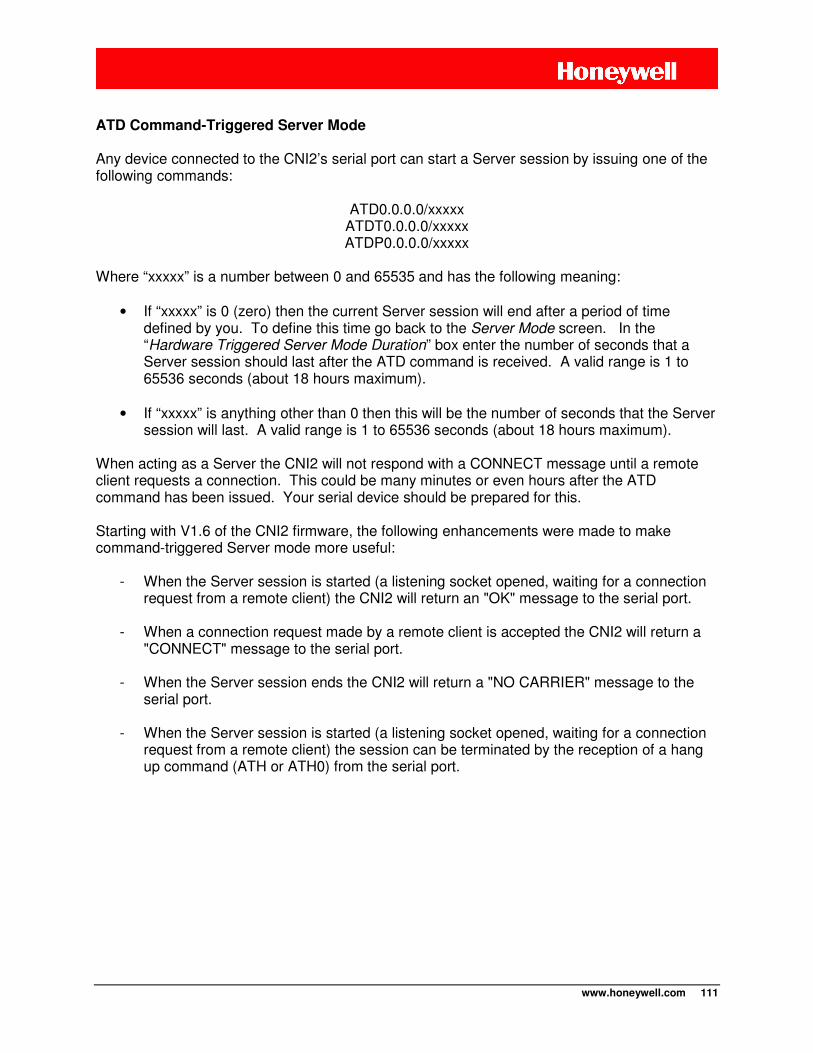
www.honeywell.com 111
ATD Command-Triggered Server Mode
Any device connected to the CNI2’s serial port can start a Server session by issuing one of the following commands:
ATD0.0.0.0/xxxxx ATDT0.0.0.0/xxxxx ATDP0.0.0.0/xxxxx
Where “xxxxx” is a number between 0 and 65535 and has the following meaning:
• If “xxxxx” is 0 (zero) then the current Server session will end after a period of time defined by you. To define this time go back to the Server Mode screen. In the “Hardware Triggered Server Mode Duration” box enter the number of seconds that a Server session should last after the ATD command is received. A valid range is 1 to 65536 seconds (about 18 hours maximum).
• If “xxxxx” is anything other than 0 then this will be the number of seconds that the Server
session will last. A valid range is 1 to 65536 seconds (about 18 hours maximum). When acting as a Server the CNI2 will not respond with a CONNECT message until a remote client requests a connection. This could be many minutes or even hours after the ATD command has been issued. Your serial device should be prepared for this. Starting with V1.6 of the CNI2 firmware, the following enhancements were made to make command-triggered Server mode more useful:
- When the Server session is started (a listening socket opened, waiting for a connection request from a remote client) the CNI2 will return an "OK" message to the serial port.
- When a connection request made by a remote client is accepted the CNI2 will return a "CONNECT" message to the serial port.
- When the Server session ends the CNI2 will return a "NO CARRIER" message to the
serial port.
- When the Server session is started (a listening socket opened, waiting for a connection request from a remote client) the session can be terminated by the reception of a hang up command (ATH or ATH0) from the serial port.
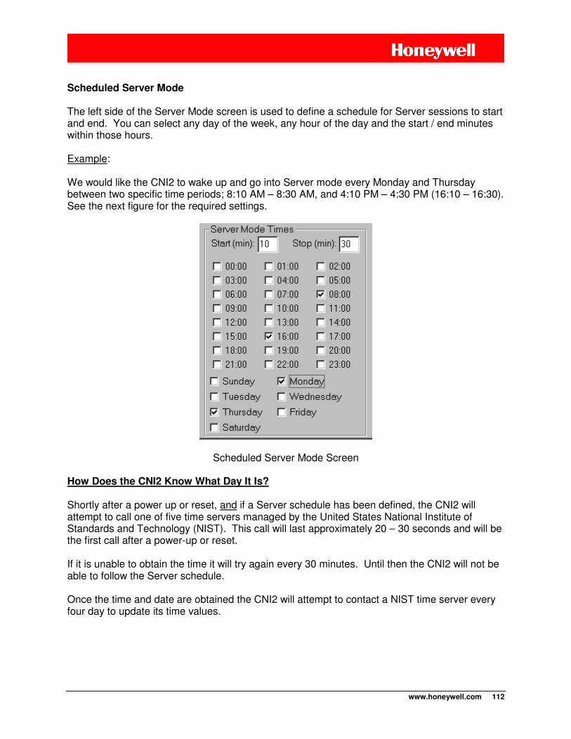
www.honeywell.com 112
Scheduled Server Mode
The left side of the Server Mode screen is used to define a schedule for Server sessions to start and end. You can select any day of the week, any hour of the day and the start / end minutes within those hours. Example: We would like the CNI2 to wake up and go into Server mode every Monday and Thursday between two specific time periods; 8:10 AM – 8:30 AM, and 4:10 PM – 4:30 PM (16:10 – 16:30). See the next figure for the required settings.
Scheduled Server Mode Screen How Does the CNI2 Know What Day It Is?
Shortly after a power up or reset, and if a Server schedule has been defined, the CNI2 will attempt to call one of five time servers managed by the United States National Institute of Standards and Technology (NIST). This call will last approximately 20 – 30 seconds and will be the first call after a power-up or reset. If it is unable to obtain the time it will try again every 30 minutes. Until then the CNI2 will not be able to follow the Server schedule. Once the time and date are obtained the CNI2 will attempt to contact a NIST time server every four day to update its time values.
www.honeywell.com 113
NOTE
The time and date obtained from a NIST time server is only used to schedule Server sessions. It is not used for call scheduling or time-tagging of pulse data or alarm events.
Daylight Savings Time (DST) adjustment If the CNI2 is located in an area that observes Daylight Savings Time (DST), and you would like the CNI2 to make that adjustment automatically, check the “Adjust for DST” box on the Server Mode screen. Example: In the United States DST starts on the 2nd Sunday in March and ends on the 1st Sunday in November. If the “Adjust for DST” box is checked the CNI2 will add one hour to the NIST time between these dates.
NOTE DST adjustment only applies to the time and date obtained from a NIST time server, which
is only used to schedule Server sessions.
It is not applied to the time that is obtained from a data collection server such as DC-2009®
or MV90®, which is used for call scheduling or time-tagging of pulse data or alarm events.
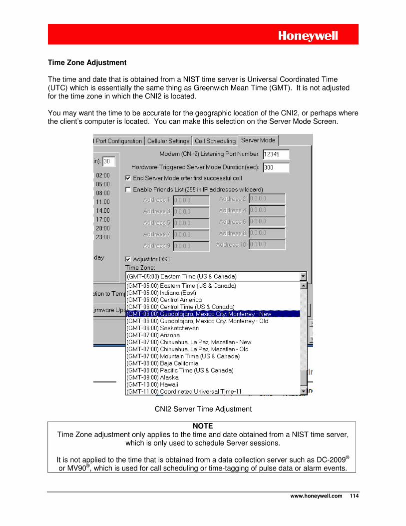
www.honeywell.com 114
Time Zone Adjustment
The time and date that is obtained from a NIST time server is Universal Coordinated Time (UTC) which is essentially the same thing as Greenwich Mean Time (GMT). It is not adjusted for the time zone in which the CNI2 is located. You may want the time to be accurate for the geographic location of the CNI2, or perhaps where the client’s computer is located. You can make this selection on the Server Mode Screen.
CNI2 Server Time Adjustment
NOTE Time Zone adjustment only applies to the time and date obtained from a NIST time server,
which is only used to schedule Server sessions.
It is not applied to the time that is obtained from a data collection server such as DC-2009®
or MV90®, which is used for call scheduling or time-tagging of pulse data or alarm events.
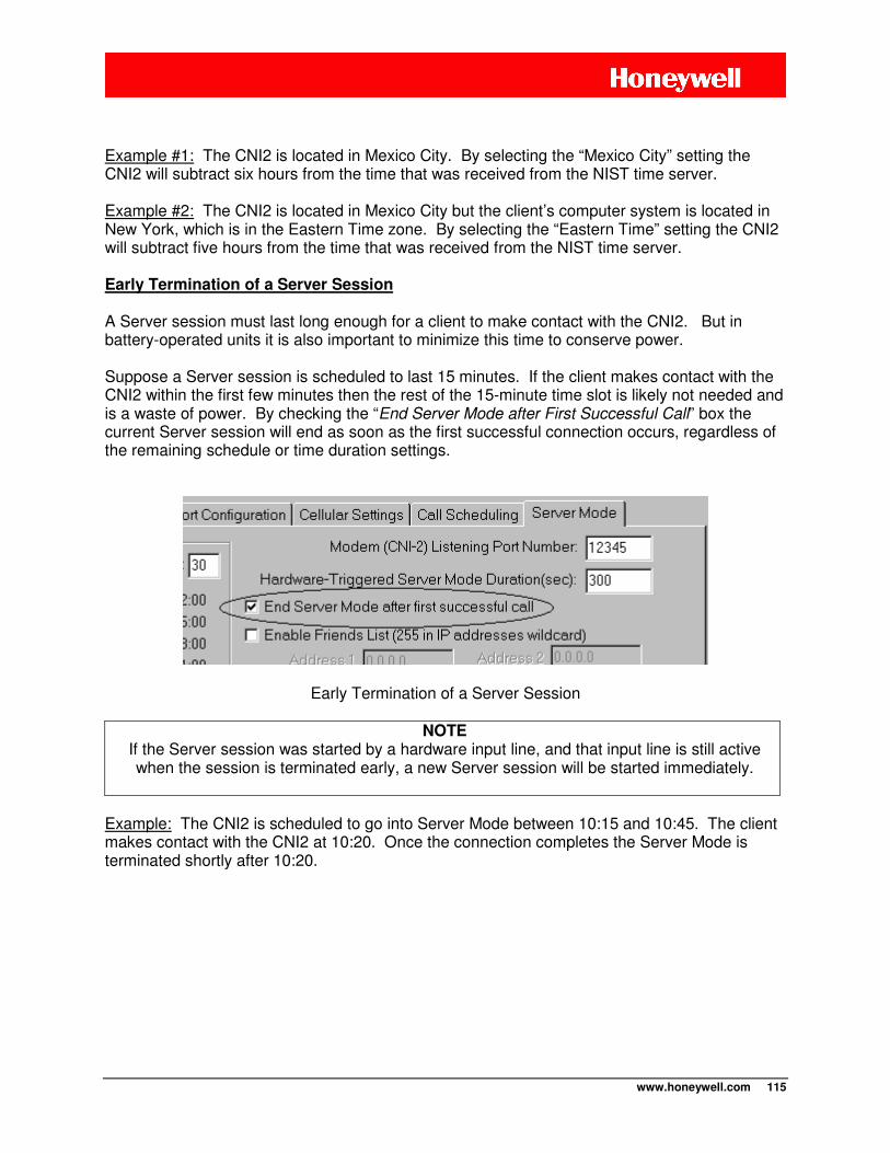
www.honeywell.com 115
Example #1: The CNI2 is located in Mexico City. By selecting the “Mexico City” setting the CNI2 will subtract six hours from the time that was received from the NIST time server. Example #2: The CNI2 is located in Mexico City but the client’s computer system is located in New York, which is in the Eastern Time zone. By selecting the “Eastern Time” setting the CNI2 will subtract five hours from the time that was received from the NIST time server. Early Termination of a Server Session
A Server session must last long enough for a client to make contact with the CNI2. But in battery-operated units it is also important to minimize this time to conserve power. Suppose a Server session is scheduled to last 15 minutes. If the client makes contact with the CNI2 within the first few minutes then the rest of the 15-minute time slot is likely not needed and is a waste of power. By checking the “End Server Mode after First Successful Call” box the current Server session will end as soon as the first successful connection occurs, regardless of the remaining schedule or time duration settings.
Early Termination of a Server Session
NOTE If the Server session was started by a hardware input line, and that input line is still active when the session is terminated early, a new Server session will be started immediately.
Example: The CNI2 is scheduled to go into Server Mode between 10:15 and 10:45. The client makes contact with the CNI2 at 10:20. Once the connection completes the Server Mode is terminated shortly after 10:20.
www.honeywell.com 116
Interruption of a Server Session While waiting for connection request from a remote client there are several ways this can be interrupted:
1) The “Originate Connections” box is checked and…
a. A hardware or event alarm occurs and the CNI2 is configured to call in to report it b. The CNI2 is scheduled to call in at a specific time of the day to report pulse data, c. The CNI2 receives a dial command from the device connected to its serial port.
2) The “Respond to Voice Calls” box is checked and…
a. The CNI2 receives a voice call (page) or a CSD call.
However once a remote client connects to the CNI2 that session will be allowed to complete and will not be interrupted by any of the events mentioned above. Depending upon how the CNI2 is configured it may return to listening for a connection request after the interruption. Example: The CNI2 is scheduled to listen for a connection request between 8:00AM – 8:45AM. At 8:15AM an alarm condition occurs that must be reported immediately. The CNI2 terminates the Server session and establishes a Client connection to a data collection system such as DC-2009®. Once the call has finished there is still time remaining on the Server schedule, so the CNI2 will reopen a listening channel and will continue to listen for a connection request until 8:45AM.
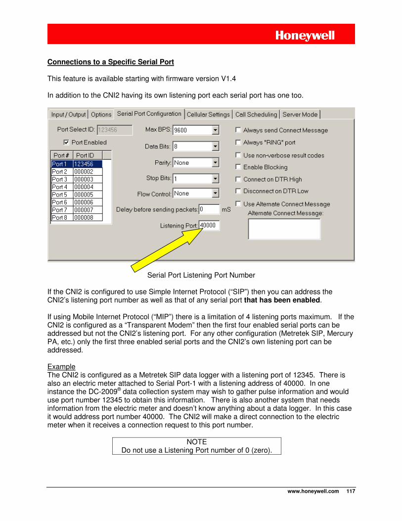
www.honeywell.com 117
Connections to a Specific Serial Port
This feature is available starting with firmware version V1.4 In addition to the CNI2 having its own listening port each serial port has one too.
Serial Port Listening Port Number
If the CNI2 is configured to use Simple Internet Protocol (“SIP”) then you can address the CNI2’s listening port number as well as that of any serial port that has been enabled. If using Mobile Internet Protocol (“MIP”) there is a limitation of 4 listening ports maximum. If the CNI2 is configured as a “Transparent Modem” then the first four enabled serial ports can be addressed but not the CNI2’s listening port. For any other configuration (Metretek SIP, Mercury PA, etc.) only the first three enabled serial ports and the CNI2’s own listening port can be addressed. Example The CNI2 is configured as a Metretek SIP data logger with a listening port of 12345. There is also an electric meter attached to Serial Port-1 with a listening address of 40000. In one instance the DC-2009® data collection system may wish to gather pulse information and would use port number 12345 to obtain this information. There is also another system that needs information from the electric meter and doesn’t know anything about a data logger. In this case it would address port number 40000. The CNI2 will make a direct connection to the electric meter when it receives a connection request to this port number.
NOTE Do not use a Listening Port number of 0 (zero).
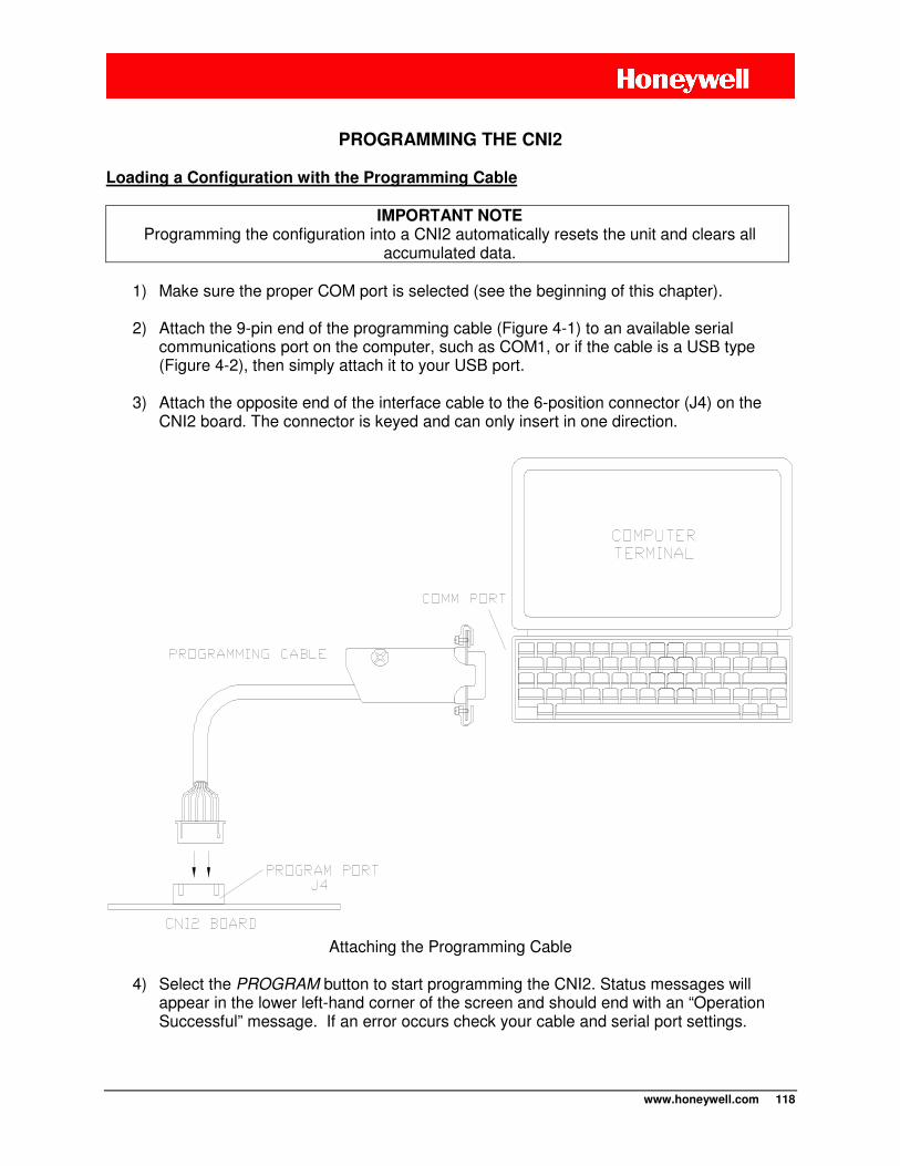
www.honeywell.com 118
PROGRAMMING THE CNI2
Loading a Configuration with the Programming Cable
IMPORTANT NOTE Programming the configuration into a CNI2 automatically resets the unit and clears all
accumulated data.
1) Make sure the proper COM port is selected (see the beginning of this chapter).
2) Attach the 9-pin end of the programming cable (Figure 4-1) to an available serial communications port on the computer, such as COM1, or if the cable is a USB type (Figure 4-2), then simply attach it to your USB port.
3) Attach the opposite end of the interface cable to the 6-position connector (J4) on the
CNI2 board. The connector is keyed and can only insert in one direction.
Attaching the Programming Cable
4) Select the PROGRAM button to start programming the CNI2. Status messages will
appear in the lower left-hand corner of the screen and should end with an “Operation Successful” message. If an error occurs check your cable and serial port settings.

www.honeywell.com 119
During programming the RED and GREEN LEDs may light as data is being transferred between the CNI2 and MP32®.
5) When programming has completed, unplug the cable from the CNI2 board. The CNI2 is now ready to be put into service.
www.honeywell.com 120
OVER-THE-AIR (OTA) PROGRAMMING What is Over-the-Air Programming?
The CNI2’s configuration and/or its operating program (called “firmware”) can be changed once the unit is installed in the field. This is called over-the-air (OTA) programming. At the present time this feature is only supported when using the DC-2009® data collection system or InvisiConnect®, and then only in Internet (IP) mode. MV90® does not support OTA changes and DC-2009® and InvisiConnect® do not support OTA in CSD mode.
NOTE
The remote unit ID (RUID) and Service Type (GSM or CDMA) cannot be changed over-the-air. These can only be changed using a programming cable.
WARNING In some case and in some countries (Canada for example) a metering device is not allowed
to have its program or configuration changed over-the-air.
Over-the-Air Configuration Changes Using DC-2009®
Both MP32® and DC-2009® must be running on the same system at the same time. The PROGRAM ACCOUNTS / LISTS button on the bottom of the main MP32 screen will be enabled only when both programs are running. Set up all configuration items as you would for any CNI2. Then select the PROGRAM ACCOUNTS / LISTS button on the bottom of the main MP32 screen. The following screen will appear.
IMPORTANT
It is extremely important that all configuration parameters be correct, especially those related to the cellular network.
Otherwise the CNI2 may not be able to contact the central office again. This will require an on-site visit to correct the problem.
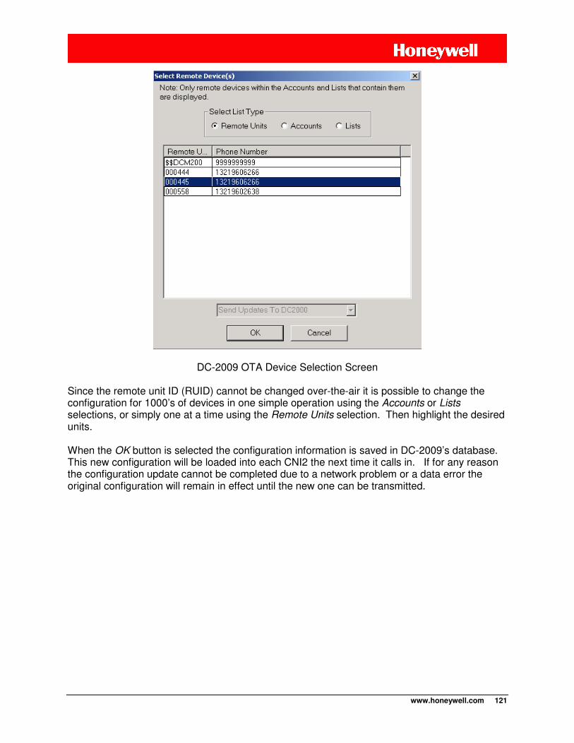
www.honeywell.com 121
DC-2009 OTA Device Selection Screen
Since the remote unit ID (RUID) cannot be changed over-the-air it is possible to change the configuration for 1000’s of devices in one simple operation using the Accounts or Lists selections, or simply one at a time using the Remote Units selection. Then highlight the desired units. When the OK button is selected the configuration information is saved in DC-2009’s database. This new configuration will be loaded into each CNI2 the next time it calls in. If for any reason the configuration update cannot be completed due to a network problem or a data error the original configuration will remain in effect until the new one can be transmitted.
www.honeywell.com 122
Over-the-Air “Firmware” Changes Using DC-2009® The CNI2’s operating software, also called “firmware”, can be changed over-the-air. Both MP32® and DC-2009® must be running on the same system at the same time.
1. Select the FIRMWARE UPDATE button on the bottom of the main MP32 screen.
2. We will provide a software file that contains the new firmware code. Enter the filename into the Firmware Filename box or use the browse button to locate it on the disk drive.
3. Select the SEND FIRMWARE UPDATE TO DC-2009 button. This button will be enabled
only when both MP32® and DC-2009® must be running on the same system at the same time.
4. See the previous screen shot. It is possible to change the firmware for 1000’s of devices
in one simple operation using the Accounts or Lists selections, or simply one at a time using the Remote Units selection. Then highlight the desired units.
5. When the OK button is selected the firmware information is saved in DC-2009’s
database. This new firmware will be loaded into each CNI2 the next time it calls in. If for any reason the firmware update cannot be completed due to a network problem or a data error the old firmware will remain in effect until the new one can be transmitted.
The CNI2 does not replace its firmware until after the call has completed. During the time that the CNI2 is reprogramming itself the green and red LEDs will alternately flash at a rapid rate. This can take up to 15 seconds to complete.
WARNING It is extremely important to select the correct firmware file.
Otherwise the CNI2 may not be able to contact the central computer again. This will require an on-site visit to correct the problem.
RECOMMENDATION
Try an over-the-air firmware update on a CNI2 that is located in your office first! If you’ve selected the wrong file you will be able to correct it before sending it to units that
are located in the field.
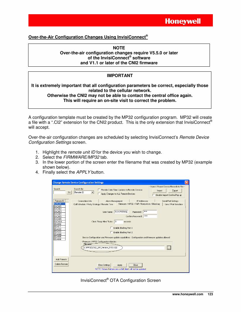
www.honeywell.com 123
Over-the-Air Configuration Changes Using InvisiConnect®
A configuration template must be created by the MP32 configuration program. MP32 will create a file with a “.CI2” extension for the CNI2 product. This is the only extension that InvisiConnect® will accept. Over-the-air configuration changes are scheduled by selecting InvisiConnect’s Remote Device Configuration Settings screen.
1. Highlight the remote unit ID for the device you wish to change. 2. Select the FIRMWARE/MP32 tab. 3. In the lower portion of the screen enter the filename that was created by MP32 (example
shown below). 4. Finally select the APPLY button.
InvisiConnect® OTA Configuration Screen
IMPORTANT
It is extremely important that all configuration parameters be correct, especially those related to the cellular network.
Otherwise the CNI2 may not be able to contact the central office again. This will require an on-site visit to correct the problem.
NOTE Over-the-air configuration changes require V5.5.0 or later
of the InvisiConnect® software and V1.1 or later of the CNI2 firmware
www.honeywell.com 124
The configuration will be updated the next time the unit calls in. If the CNI2 has been configured as a Metretek SIP going through InvisiConnect® then the configuration is changed after the CNI2 has completed its transaction with DC-2009® or MV90®. The CNI2 does not replace its configuration until after the call has completed. During the time that the CNI2 is reprogramming itself the green and red LEDs will alternately flash at a rapid rate. This can take up to 2 seconds to complete. Over-the-Air Firmware Changes Using InvisiConnect®
You will be supplied with a firmware files with a “.HEX” extension. This is the only extension that InvisiConnect® will accept. Over-the-air firmware changes are scheduled by selecting InvisiConnect’s Remote Device Configuration Settings screen.
1. Highlight the remote unit ID for the device you wish to change. 2. Select the FIRMWARE/MP32 tab. 3. In the lower portion of the screen enter the filename that was provided (example shown
in the next screenshot). 4. Finally select the APPLY button.
IMPORTANT It is extremely important to select the correct firmware file.
Otherwise the CNI2 may not be able to contact the central computer again. This will require an on-site visit to correct the problem.
NOTE Over-the-air firmware changes require V5.5.0 or later
of the InvisiConnect® software and V1.1 or later of the CNI2 firmware
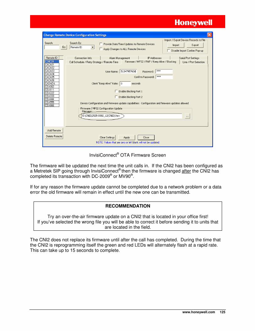
www.honeywell.com 125
InvisiConnect® OTA Firmware Screen The firmware will be updated the next time the unit calls in. If the CNI2 has been configured as a Metretek SIP going through InvisiConnect® then the firmware is changed after the CNI2 has completed its transaction with DC-2009® or MV90®. If for any reason the firmware update cannot be completed due to a network problem or a data error the old firmware will remain in effect until the new one can be transmitted.
The CNI2 does not replace its firmware until after the call has completed. During the time that the CNI2 is reprogramming itself the green and red LEDs will alternately flash at a rapid rate. This can take up to 15 seconds to complete.
RECOMMENDATION
Try an over-the-air firmware update on a CNI2 that is located in your office first! If you’ve selected the wrong file you will be able to correct it before sending it to units that
are located in the field.
www.honeywell.com 126
Some data collection systems may not support Metretek devices but may support Mercury Instruments devices. The CNI2 can emulate either a Mercury Pulse Accumulator or a Mini-Max corrector (pulse and alarm information only, the CNI2 does not measure pressure or temperature or perform any calculations based on these two measurements). DC-2009®, Masterlink® and AutoSol® support both of these instruments. MV90® can support either instrument depending upon which options were purchased for MV90®.
WHAT ARE ITEM CODES?
An “Item Code” is a 3-digit number that describes the information to be written to or read from a Mercury device. For example, Item-203 is used to load or read the current time and Item-204 the current date. Not all Mercury devices support all Item Codes. For example, since a real Mini-Max measures gas pressure, it supports Item-8, which is the current gas pressure reading. But a Pulse Accumulator knows nothing about gas pressure. Most data collection programs would know not to ask a Pulse Accumulator for Item-8. But if it were asked for Item-8, a real Pulse Accumulator would respond with a “Not Supported” error message.
DIFFERENCES BETWEEN METRETEK AND MERCURY DEVICES
• For the CNI2 to emulate a Pulse Accumulator or Mini-Max it will respond to nearly 350 Item Codes that are a combination of codes supported by both instruments. So in the previous example, if the CNI2 is configured as a Pulse Accumulator and is asked for Item-8, it will respond with a value of 0.0 rather than “Not Supported”. Some programs like Masterlink® allow certain items to be written into, including Item-8. If this happens, and the CNI2 is then asked for Item-8, it will report the new value instead of 0.0.
• Metretek pulse accumulators gather and report raw pulse counts. If these counts need
to be corrected or converted to some other value, this is done by the data collection system, namely DC-2009®. Mercury Instruments devices also gather raw pulse counts. However, if these counts need to be corrected or converted to some other value, this is generally done by the instrument before being reported to the data collection system. There are many Item Codes that a Mercury device uses to correct and convert these counts. These are described shortly.
• Newer versions of a real Mini-Max support what is known as Event Logs and Alarm
Logs. A real Pulse Accumulator, as well as the CNI2, does not currently support these features.
• A Metretek pulse accumulator can gather and report pulse counts from four independent
sources. A Pulse Accumulator is limited to two channels, and a Mini-Max one channel. If the CNI2 is configured as a Mini-Max it can report the 2nd channel’s information if it is asked for that information. However most data collection systems are not designed to ask for a 2nd channel of information from a Mini-Max.
MERCURY INSTRUMENTS EMULATION
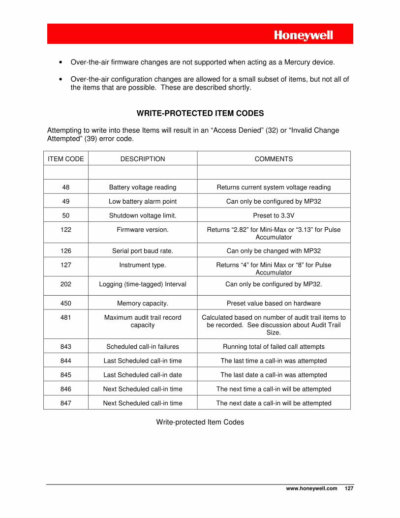
www.honeywell.com 127
• Over-the-air firmware changes are not supported when acting as a Mercury device.
• Over-the-air configuration changes are allowed for a small subset of items, but not all of
the items that are possible. These are described shortly.
WRITE-PROTECTED ITEM CODES
Attempting to write into these Items will result in an “Access Denied” (32) or “Invalid Change Attempted” (39) error code.
ITEM CODE DESCRIPTION COMMENTS
48 Battery voltage reading Returns current system voltage reading
49 Low battery alarm point Can only be configured by MP32
50 Shutdown voltage limit. Preset to 3.3V
122 Firmware version. Returns “2.82” for Mini-Max or “3.13” for Pulse Accumulator
126 Serial port baud rate. Can only be changed with MP32
127 Instrument type. Returns “4” for Mini Max or “8” for Pulse Accumulator
202 Logging (time-tagged) Interval Can only be configured by MP32.
450 Memory capacity. Preset value based on hardware
481 Maximum audit trail record capacity
Calculated based on number of audit trail items to be recorded. See discussion about Audit Trail
Size.
843 Scheduled call-in failures Running total of failed call attempts
844 Last Scheduled call-in time The last time a call-in was attempted
845 Last Scheduled call-in date The last date a call-in was attempted
846 Next Scheduled call-in time The next time a call-in will be attempted
847 Next Scheduled call-in time The next date a call-in will be attempted
Write-protected Item Codes
www.honeywell.com 128
ITEM CODES PROTECTED BY ITEM-139
Item-139 is used to protect some or all other item codes from being changed, as follows: 0 = Full read/write access. 1 = Read access only, no write access is permitted 2 = No read/write access from the local serial port 3 = Full read/write access except for metrological items
If Item-139 is set to 2 and an attempt is made to access the items via the local serial port (for instance using Masterlink®), the CNI2 will return the “Access Denied” (32) error code. Attempting to write into items protected by Item-139 will result in an “Access Denied” (32) or “Invalid Change Attempted” (39) error code.
NOTE
A “Metrological” item is any item that affects the accuracy of the pulse-count readings. Examples include scaling factors, calibration constants, energy-related conversion
factors, etc.
Item-139 is also considered a metrological item. If you write 1, 2 or 3 into Item-139, you will not be able to change it back to 0. Therefore writing to Item-139 should be the last
thing you do before putting the CNI2 into service.
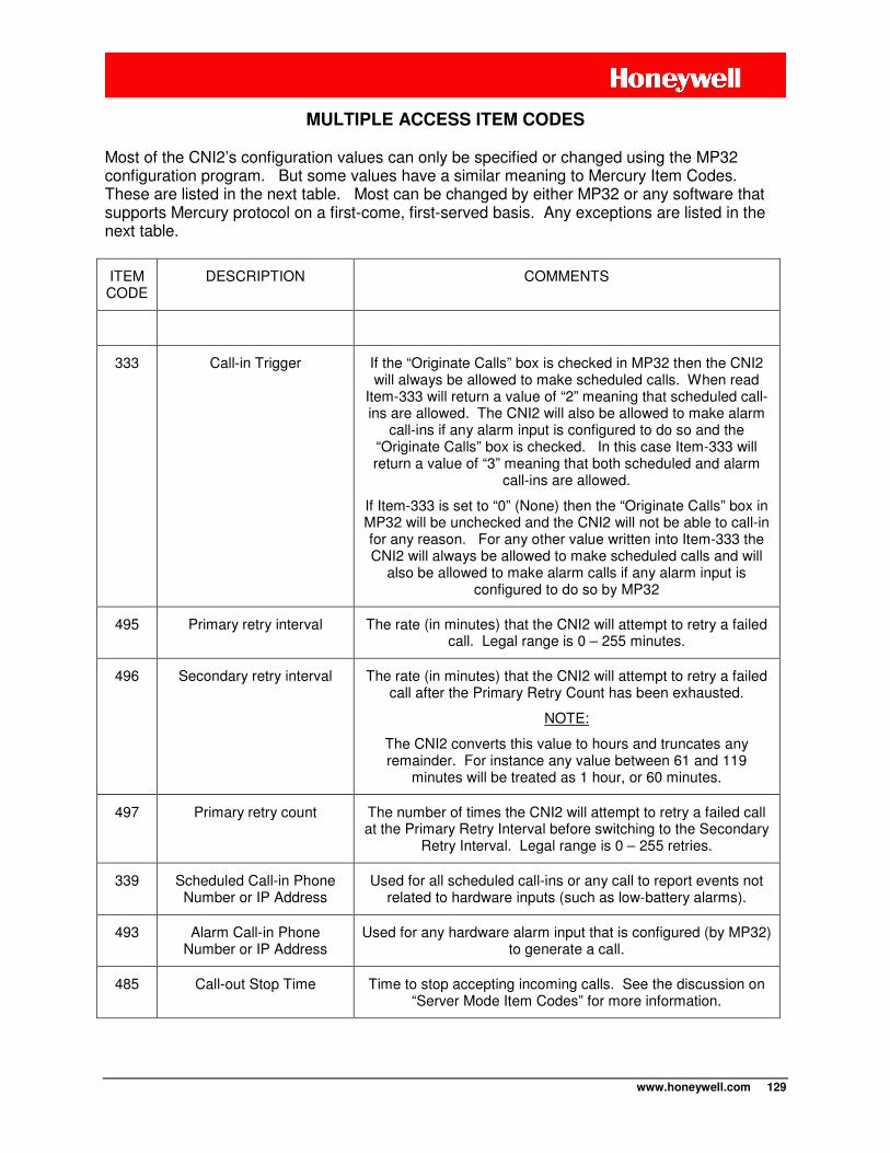
www.honeywell.com 129
MULTIPLE ACCESS ITEM CODES Most of the CNI2’s configuration values can only be specified or changed using the MP32 configuration program. But some values have a similar meaning to Mercury Item Codes. These are listed in the next table. Most can be changed by either MP32 or any software that supports Mercury protocol on a first-come, first-served basis. Any exceptions are listed in the next table.
ITEM CODE
DESCRIPTION COMMENTS
333 Call-in Trigger If the “Originate Calls” box is checked in MP32 then the CNI2 will always be allowed to make scheduled calls. When read
Item-333 will return a value of “2” meaning that scheduled call-ins are allowed. The CNI2 will also be allowed to make alarm
call-ins if any alarm input is configured to do so and the “Originate Calls” box is checked. In this case Item-333 will return a value of “3” meaning that both scheduled and alarm
call-ins are allowed.
If Item-333 is set to “0” (None) then the “Originate Calls” box in MP32 will be unchecked and the CNI2 will not be able to call-in for any reason. For any other value written into Item-333 the CNI2 will always be allowed to make scheduled calls and will
also be allowed to make alarm calls if any alarm input is configured to do so by MP32
495 Primary retry interval The rate (in minutes) that the CNI2 will attempt to retry a failed call. Legal range is 0 – 255 minutes.
496 Secondary retry interval The rate (in minutes) that the CNI2 will attempt to retry a failed call after the Primary Retry Count has been exhausted.
NOTE:
The CNI2 converts this value to hours and truncates any remainder. For instance any value between 61 and 119
minutes will be treated as 1 hour, or 60 minutes.
497 Primary retry count The number of times the CNI2 will attempt to retry a failed call at the Primary Retry Interval before switching to the Secondary
Retry Interval. Legal range is 0 – 255 retries.
339 Scheduled Call-in Phone Number or IP Address
Used for all scheduled call-ins or any call to report events not related to hardware inputs (such as low-battery alarms).
493 Alarm Call-in Phone Number or IP Address
Used for any hardware alarm input that is configured (by MP32) to generate a call.
485 Call-out Stop Time Time to stop accepting incoming calls. See the discussion on “Server Mode Item Codes” for more information.
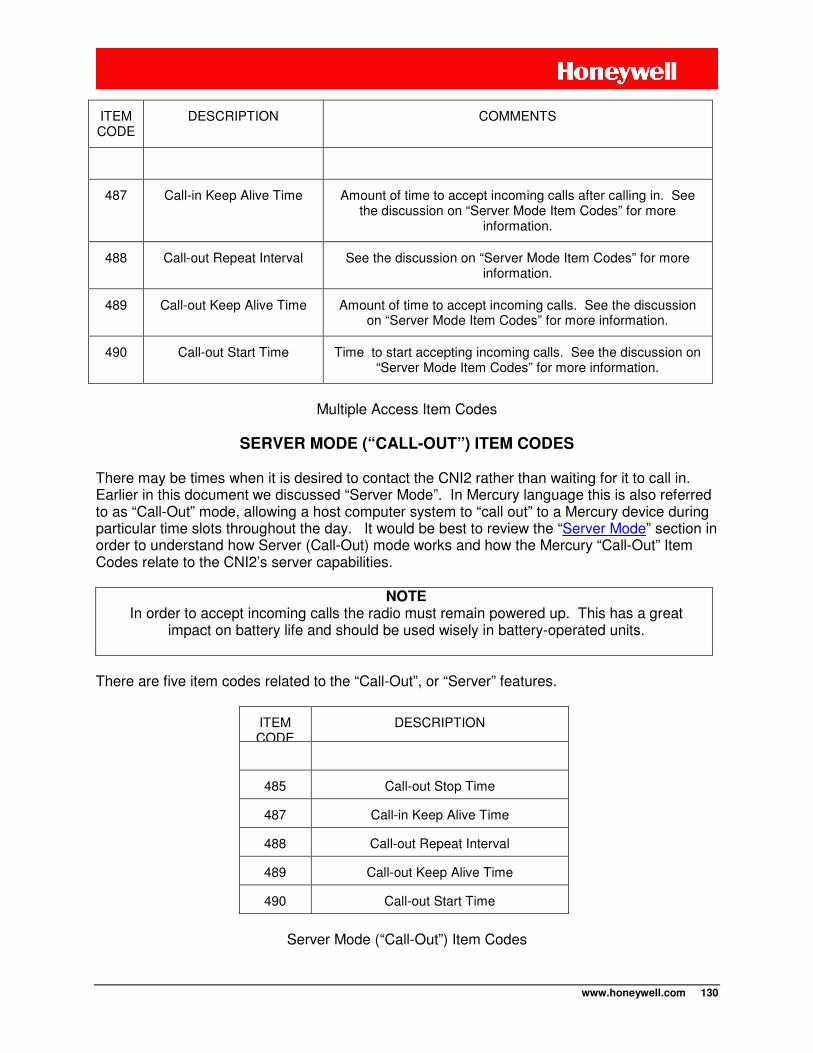
www.honeywell.com 130
ITEM CODE
DESCRIPTION COMMENTS
487 Call-in Keep Alive Time Amount of time to accept incoming calls after calling in. See the discussion on “Server Mode Item Codes” for more
information.
488 Call-out Repeat Interval See the discussion on “Server Mode Item Codes” for more information.
489 Call-out Keep Alive Time Amount of time to accept incoming calls. See the discussion on “Server Mode Item Codes” for more information.
490 Call-out Start Time Time to start accepting incoming calls. See the discussion on “Server Mode Item Codes” for more information.
Multiple Access Item Codes
SERVER MODE (“CALL-OUT”) ITEM CODES
There may be times when it is desired to contact the CNI2 rather than waiting for it to call in. Earlier in this document we discussed “Server Mode”. In Mercury language this is also referred to as “Call-Out” mode, allowing a host computer system to “call out” to a Mercury device during particular time slots throughout the day. It would be best to review the “Server Mode” section in order to understand how Server (Call-Out) mode works and how the Mercury “Call-Out” Item Codes relate to the CNI2’s server capabilities.
NOTE In order to accept incoming calls the radio must remain powered up. This has a great
impact on battery life and should be used wisely in battery-operated units.
There are five item codes related to the “Call-Out”, or “Server” features.
ITEM CODE
DESCRIPTION
485 Call-out Stop Time
487 Call-in Keep Alive Time
488 Call-out Repeat Interval
489 Call-out Keep Alive Time
490 Call-out Start Time
Server Mode (“Call-Out”) Item Codes
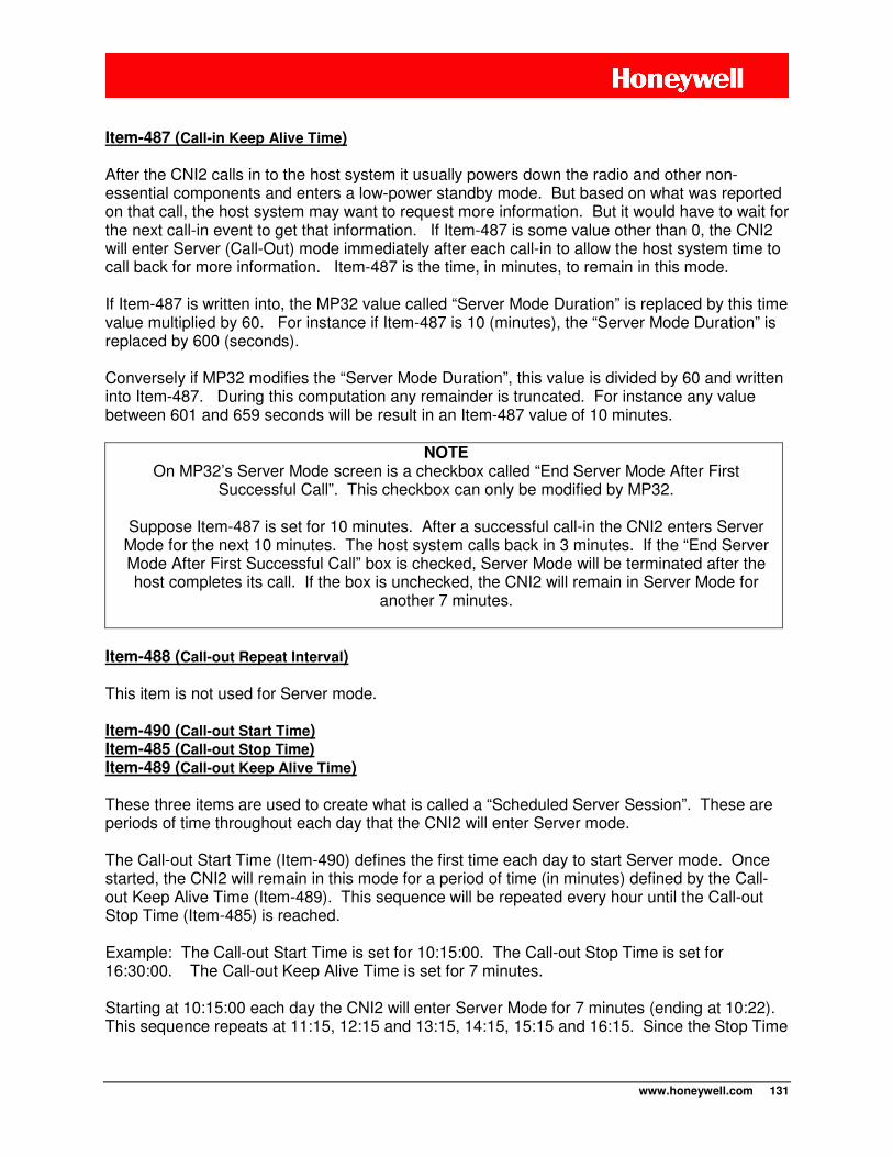
www.honeywell.com 131
Item-487 (Call-in Keep Alive Time) After the CNI2 calls in to the host system it usually powers down the radio and other non-essential components and enters a low-power standby mode. But based on what was reported on that call, the host system may want to request more information. But it would have to wait for the next call-in event to get that information. If Item-487 is some value other than 0, the CNI2 will enter Server (Call-Out) mode immediately after each call-in to allow the host system time to call back for more information. Item-487 is the time, in minutes, to remain in this mode. If Item-487 is written into, the MP32 value called “Server Mode Duration” is replaced by this time value multiplied by 60. For instance if Item-487 is 10 (minutes), the “Server Mode Duration” is replaced by 600 (seconds). Conversely if MP32 modifies the “Server Mode Duration”, this value is divided by 60 and written into Item-487. During this computation any remainder is truncated. For instance any value between 601 and 659 seconds will be result in an Item-487 value of 10 minutes.
NOTE On MP32’s Server Mode screen is a checkbox called “End Server Mode After First
Successful Call”. This checkbox can only be modified by MP32.
Suppose Item-487 is set for 10 minutes. After a successful call-in the CNI2 enters Server Mode for the next 10 minutes. The host system calls back in 3 minutes. If the “End Server Mode After First Successful Call” box is checked, Server Mode will be terminated after the host completes its call. If the box is unchecked, the CNI2 will remain in Server Mode for
another 7 minutes.
Item-488 (Call-out Repeat Interval)
This item is not used for Server mode. Item-490 (Call-out Start Time) Item-485 (Call-out Stop Time) Item-489 (Call-out Keep Alive Time)
These three items are used to create what is called a “Scheduled Server Session”. These are periods of time throughout each day that the CNI2 will enter Server mode. The Call-out Start Time (Item-490) defines the first time each day to start Server mode. Once started, the CNI2 will remain in this mode for a period of time (in minutes) defined by the Call-out Keep Alive Time (Item-489). This sequence will be repeated every hour until the Call-out Stop Time (Item-485) is reached. Example: The Call-out Start Time is set for 10:15:00. The Call-out Stop Time is set for 16:30:00. The Call-out Keep Alive Time is set for 7 minutes. Starting at 10:15:00 each day the CNI2 will enter Server Mode for 7 minutes (ending at 10:22). This sequence repeats at 11:15, 12:15 and 13:15, 14:15, 15:15 and 16:15. Since the Stop Time
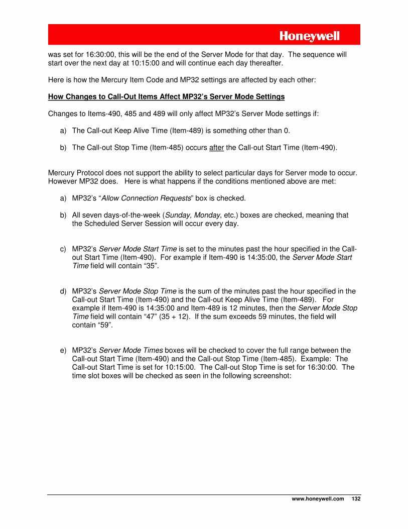
www.honeywell.com 132
was set for 16:30:00, this will be the end of the Server Mode for that day. The sequence will start over the next day at 10:15:00 and will continue each day thereafter. Here is how the Mercury Item Code and MP32 settings are affected by each other: How Changes to Call-Out Items Affect MP32’s Server Mode Settings Changes to Items-490, 485 and 489 will only affect MP32’s Server Mode settings if:
a) The Call-out Keep Alive Time (Item-489) is something other than 0.
b) The Call-out Stop Time (Item-485) occurs after the Call-out Start Time (Item-490).
Mercury Protocol does not support the ability to select particular days for Server mode to occur. However MP32 does. Here is what happens if the conditions mentioned above are met:
a) MP32’s “Allow Connection Requests” box is checked.
b) All seven days-of-the-week (Sunday, Monday, etc.) boxes are checked, meaning that the Scheduled Server Session will occur every day.
c) MP32’s Server Mode Start Time is set to the minutes past the hour specified in the Call-out Start Time (Item-490). For example if Item-490 is 14:35:00, the Server Mode Start Time field will contain “35”.
d) MP32’s Server Mode Stop Time is the sum of the minutes past the hour specified in the Call-out Start Time (Item-490) and the Call-out Keep Alive Time (Item-489). For example if Item-490 is 14:35:00 and Item-489 is 12 minutes, then the Server Mode Stop Time field will contain “47” (35 + 12). If the sum exceeds 59 minutes, the field will contain “59”.
e) MP32’s Server Mode Times boxes will be checked to cover the full range between the Call-out Start Time (Item-490) and the Call-out Stop Time (Item-485). Example: The Call-out Start Time is set for 10:15:00. The Call-out Stop Time is set for 16:30:00. The time slot boxes will be checked as seen in the following screenshot:
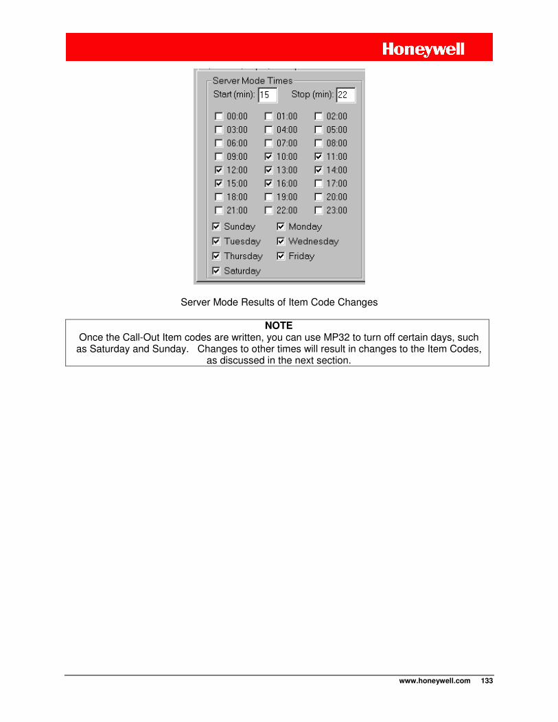
www.honeywell.com 133
Server Mode Results of Item Code Changes
NOTE Once the Call-Out Item codes are written, you can use MP32 to turn off certain days, such
as Saturday and Sunday. Changes to other times will result in changes to the Item Codes, as discussed in the next section.
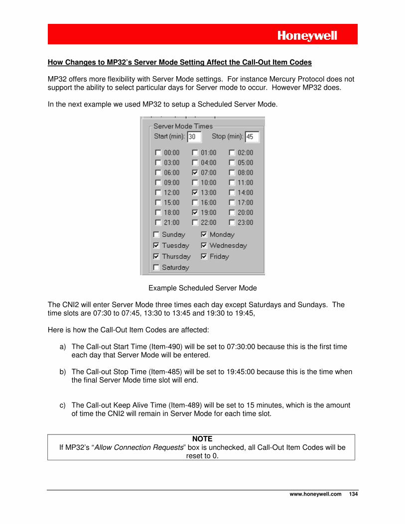
www.honeywell.com 134
How Changes to MP32’s Server Mode Setting Affect the Call-Out Item Codes MP32 offers more flexibility with Server Mode settings. For instance Mercury Protocol does not support the ability to select particular days for Server mode to occur. However MP32 does. In the next example we used MP32 to setup a Scheduled Server Mode.
Example Scheduled Server Mode The CNI2 will enter Server Mode three times each day except Saturdays and Sundays. The time slots are 07:30 to 07:45, 13:30 to 13:45 and 19:30 to 19:45, Here is how the Call-Out Item Codes are affected:
a) The Call-out Start Time (Item-490) will be set to 07:30:00 because this is the first time each day that Server Mode will be entered.
b) The Call-out Stop Time (Item-485) will be set to 19:45:00 because this is the time when the final Server Mode time slot will end.
c) The Call-out Keep Alive Time (Item-489) will be set to 15 minutes, which is the amount of time the CNI2 will remain in Server Mode for each time slot.
NOTE If MP32’s “Allow Connection Requests” box is unchecked, all Call-Out Item Codes will be
reset to 0.
www.honeywell.com 135
MEASUREMENT (PULSE-COUNTING) ITEM CODES
Mercury Instruments devices gather (and can report) raw pulse counts. However, if these counts need to be corrected or converted to some other value, this is generally done by the device before being reported to the data collection system. There are many Item Codes that a Mercury device uses to correct and convert these counts.
NOTE
The CNI2 has multiple input lines that can be configured as pulse-counting inputs. The very 1st line configured for pulse-counting is called “Channel-1”.
The 2nd line configured for pulse-counting is called “Channel-2”.
ITEM CODE
LEGACY DESCRIPTION
as a MINI-MAX
LEGACY DESCRIPTION
as a PULSE ACCUMULATOR
0 Corrected Volume Channel-1 Fixed Factor Volume
2 Uncorrected Volume Channel-1 Accumulated Volume
44 Pressure Correction Factor Channel-1 Fixed Factor Value
90 Corrected Volume Units Channel-1 Fixed Factor Volume Units
92 Uncorrected Volume Units Channel-1 Accumulated Volume Units
98 Meter Index Rate Channel-1 Input Pulse Value
114 Meter Scaling Factor Channel-1 Input Pulse Scaling Factor
140 Energy Channel-1 Energy
141 Energy Units Channel-1 Energy Units
142 Gas Energy Value Channel-1 Gas Energy Value
190 Daily Energy Channel-1 Daily Energy
221 Daily Corrected Volume Alarm Limit Channel-1 Daily Fixed Factor Volume Alarm Limit
222 Daily Corrected Volume Alarm Indicator
Channel-1 Daily Fixed Factor Volume Alarm Indicator
223 Daily Corrected Volume Channel-1 Daily Fixed Factor Volume
224 Daily Uncorrected Volume Channel-1 Daily Accumulated Volume
225 Incremental Corrected Volume Channel-1 Incremental Fixed Factor Volume
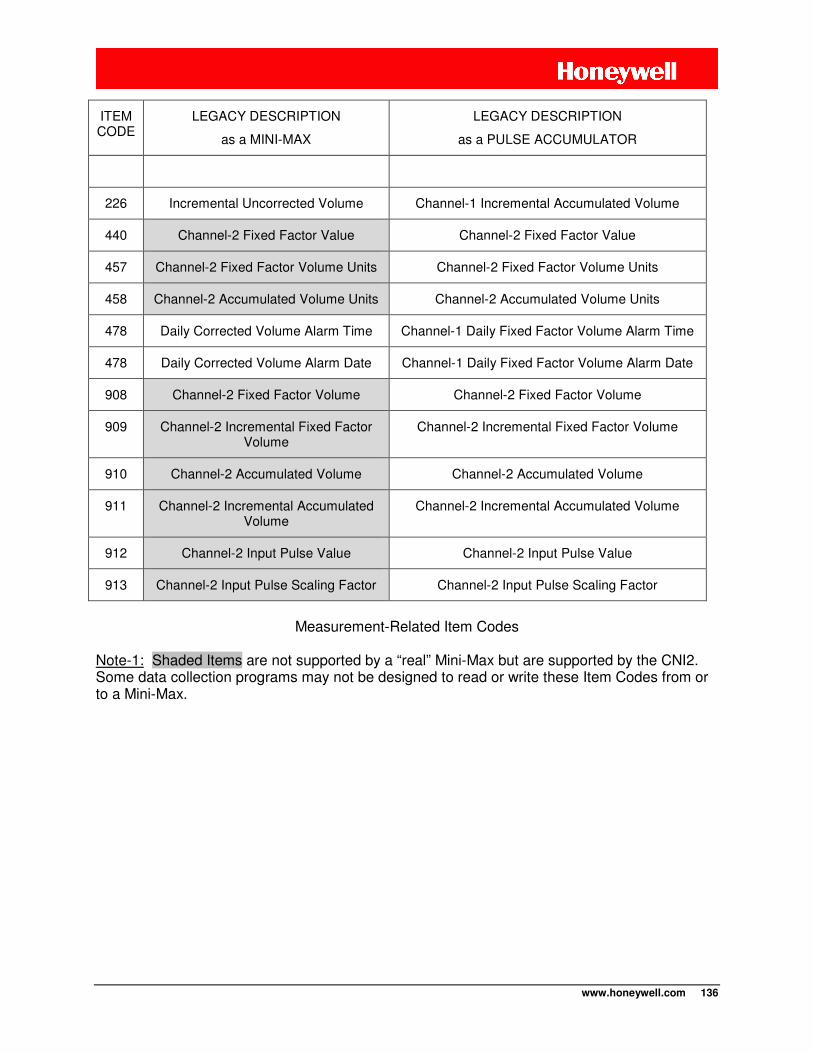
www.honeywell.com 136
ITEM CODE
LEGACY DESCRIPTION
as a MINI-MAX
LEGACY DESCRIPTION
as a PULSE ACCUMULATOR
226 Incremental Uncorrected Volume Channel-1 Incremental Accumulated Volume
440 Channel-2 Fixed Factor Value Channel-2 Fixed Factor Value
457 Channel-2 Fixed Factor Volume Units Channel-2 Fixed Factor Volume Units
458 Channel-2 Accumulated Volume Units Channel-2 Accumulated Volume Units
478 Daily Corrected Volume Alarm Time Channel-1 Daily Fixed Factor Volume Alarm Time
478 Daily Corrected Volume Alarm Date Channel-1 Daily Fixed Factor Volume Alarm Date
908 Channel-2 Fixed Factor Volume Channel-2 Fixed Factor Volume
909 Channel-2 Incremental Fixed Factor Volume
Channel-2 Incremental Fixed Factor Volume
910 Channel-2 Accumulated Volume Channel-2 Accumulated Volume
911 Channel-2 Incremental Accumulated Volume
Channel-2 Incremental Accumulated Volume
912 Channel-2 Input Pulse Value Channel-2 Input Pulse Value
913 Channel-2 Input Pulse Scaling Factor Channel-2 Input Pulse Scaling Factor
Measurement-Related Item Codes
Note-1: Shaded Items are not supported by a “real” Mini-Max but are supported by the CNI2. Some data collection programs may not be designed to read or write these Item Codes from or to a Mini-Max.
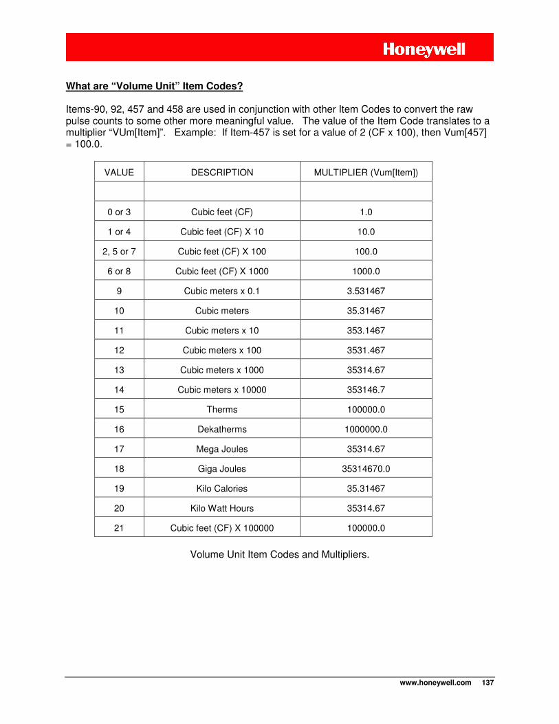
www.honeywell.com 137
What are “Volume Unit” Item Codes?
Items-90, 92, 457 and 458 are used in conjunction with other Item Codes to convert the raw pulse counts to some other more meaningful value. The value of the Item Code translates to a multiplier “VUm[Item]”. Example: If Item-457 is set for a value of 2 (CF x 100), then Vum[457] = 100.0.
VALUE DESCRIPTION MULTIPLIER (Vum[Item])
0 or 3 Cubic feet (CF) 1.0
1 or 4 Cubic feet (CF) X 10 10.0
2, 5 or 7 Cubic feet (CF) X 100 100.0
6 or 8 Cubic feet (CF) X 1000 1000.0
9 Cubic meters x 0.1 3.531467
10 Cubic meters 35.31467
11 Cubic meters x 10 353.1467
12 Cubic meters x 100 3531.467
13 Cubic meters x 1000 35314.67
14 Cubic meters x 10000 353146.7
15 Therms 100000.0
16 Dekatherms 1000000.0
17 Mega Joules 35314.67
18 Giga Joules 35314670.0
19 Kilo Calories 35.31467
20 Kilo Watt Hours 35314.67
21 Cubic feet (CF) X 100000 100000.0
Volume Unit Item Codes and Multipliers.
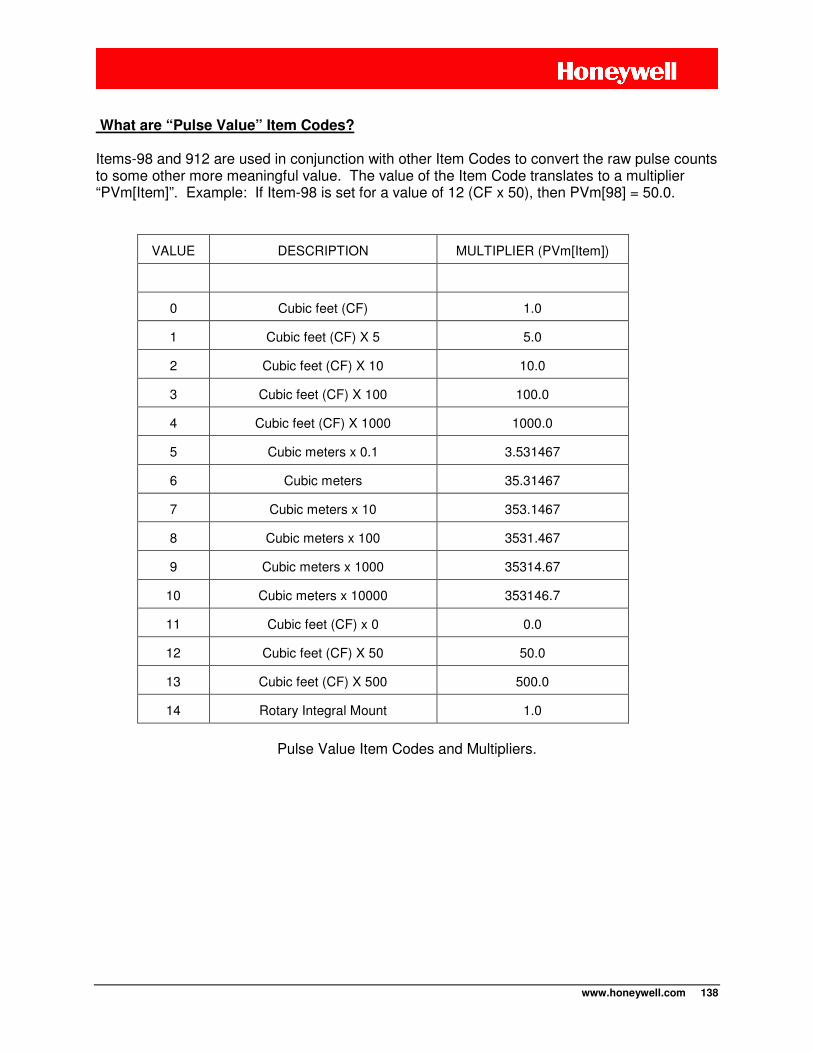
www.honeywell.com 138
What are “Pulse Value” Item Codes? Items-98 and 912 are used in conjunction with other Item Codes to convert the raw pulse counts to some other more meaningful value. The value of the Item Code translates to a multiplier “PVm[Item]”. Example: If Item-98 is set for a value of 12 (CF x 50), then PVm[98] = 50.0.
VALUE DESCRIPTION MULTIPLIER (PVm[Item])
0 Cubic feet (CF) 1.0
1 Cubic feet (CF) X 5 5.0
2 Cubic feet (CF) X 10 10.0
3 Cubic feet (CF) X 100 100.0
4 Cubic feet (CF) X 1000 1000.0
5 Cubic meters x 0.1 3.531467
6 Cubic meters 35.31467
7 Cubic meters x 10 353.1467
8 Cubic meters x 100 3531.467
9 Cubic meters x 1000 35314.67
10 Cubic meters x 10000 353146.7
11 Cubic feet (CF) x 0 0.0
12 Cubic feet (CF) X 50 50.0
13 Cubic feet (CF) X 500 500.0
14 Rotary Integral Mount 1.0
Pulse Value Item Codes and Multipliers.
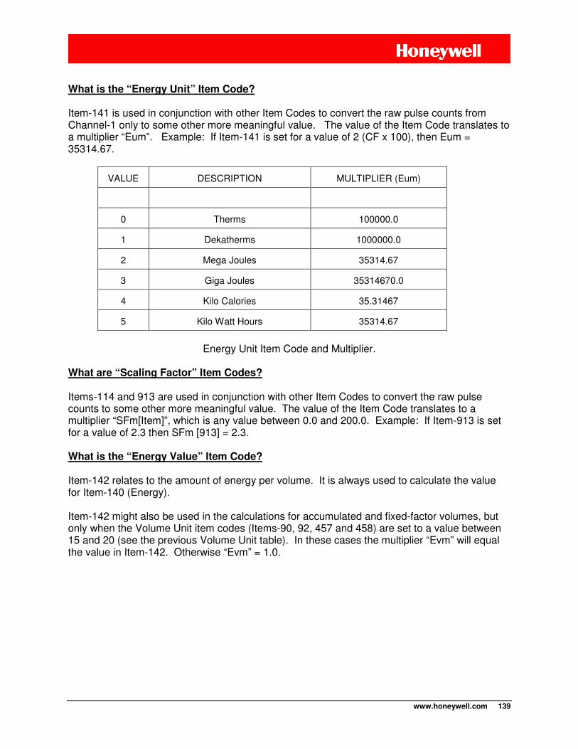
www.honeywell.com 139
What is the “Energy Unit” Item Code?
Item-141 is used in conjunction with other Item Codes to convert the raw pulse counts from Channel-1 only to some other more meaningful value. The value of the Item Code translates to a multiplier “Eum”. Example: If Item-141 is set for a value of 2 (CF x 100), then Eum = 35314.67.
VALUE DESCRIPTION MULTIPLIER (Eum)
0 Therms 100000.0
1 Dekatherms 1000000.0
2 Mega Joules 35314.67
3 Giga Joules 35314670.0
4 Kilo Calories 35.31467
5 Kilo Watt Hours 35314.67
Energy Unit Item Code and Multiplier.
What are “Scaling Factor” Item Codes? Items-114 and 913 are used in conjunction with other Item Codes to convert the raw pulse counts to some other more meaningful value. The value of the Item Code translates to a multiplier “SFm[Item]”, which is any value between 0.0 and 200.0. Example: If Item-913 is set for a value of 2.3 then SFm [913] = 2.3. What is the “Energy Value” Item Code? Item-142 relates to the amount of energy per volume. It is always used to calculate the value for Item-140 (Energy). Item-142 might also be used in the calculations for accumulated and fixed-factor volumes, but only when the Volume Unit item codes (Items-90, 92, 457 and 458) are set to a value between 15 and 20 (see the previous Volume Unit table). In these cases the multiplier “Evm” will equal the value in Item-142. Otherwise “Evm” = 1.0.
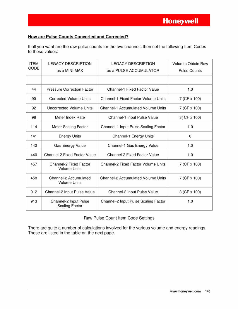
www.honeywell.com 140
How are Pulse Counts Converted and Corrected? If all you want are the raw pulse counts for the two channels then set the following Item Codes to these values:
ITEM CODE
LEGACY DESCRIPTION
as a MINI-MAX
LEGACY DESCRIPTION
as a PULSE ACCUMULATOR
Value to Obtain Raw
Pulse Counts
44 Pressure Correction Factor Channel-1 Fixed Factor Value 1.0
90 Corrected Volume Units Channel-1 Fixed Factor Volume Units 7 (CF x 100)
92 Uncorrected Volume Units Channel-1 Accumulated Volume Units 7 (CF x 100)
98 Meter Index Rate Channel-1 Input Pulse Value 3( CF x 100)
114 Meter Scaling Factor Channel-1 Input Pulse Scaling Factor 1.0
141 Energy Units Channel-1 Energy Units 0
142 Gas Energy Value Channel-1 Gas Energy Value 1.0
440 Channel-2 Fixed Factor Value Channel-2 Fixed Factor Value 1.0
457 Channel-2 Fixed Factor Volume Units
Channel-2 Fixed Factor Volume Units 7 (CF x 100)
458 Channel-2 Accumulated Volume Units
Channel-2 Accumulated Volume Units 7 (CF x 100)
912 Channel-2 Input Pulse Value Channel-2 Input Pulse Value 3 (CF x 100)
913 Channel-2 Input Pulse Scaling Factor
Channel-2 Input Pulse Scaling Factor 1.0
Raw Pulse Count Item Code Settings
There are quite a number of calculations involved for the various volume and energy readings. These are listed in the table on the next page.
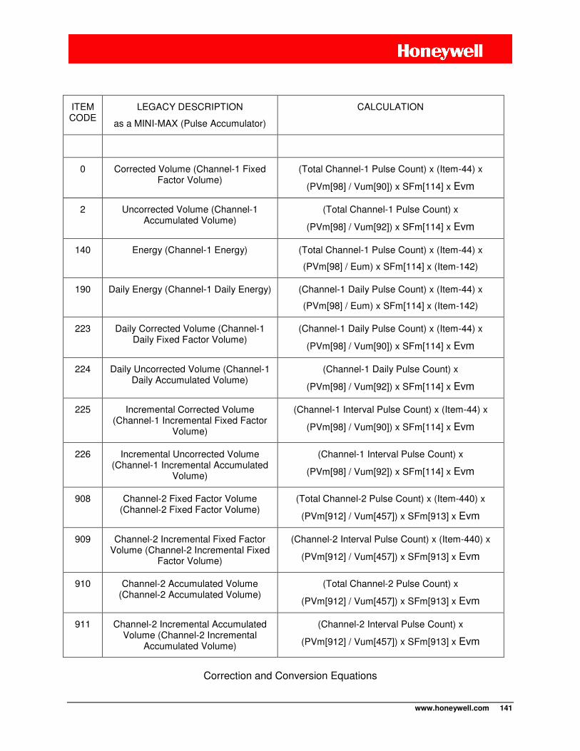
www.honeywell.com 141
ITEM CODE
LEGACY DESCRIPTION
as a MINI-MAX (Pulse Accumulator)
CALCULATION
0 Corrected Volume (Channel-1 Fixed Factor Volume)
(Total Channel-1 Pulse Count) x (Item-44) x
(PVm[98] / Vum[90]) x SFm[114] x Evm
2 Uncorrected Volume (Channel-1 Accumulated Volume)
(Total Channel-1 Pulse Count) x
(PVm[98] / Vum[92]) x SFm[114] x Evm
140 Energy (Channel-1 Energy) (Total Channel-1 Pulse Count) x (Item-44) x
(PVm[98] / Eum) x SFm[114] x (Item-142)
190 Daily Energy (Channel-1 Daily Energy) (Channel-1 Daily Pulse Count) x (Item-44) x
(PVm[98] / Eum) x SFm[114] x (Item-142)
223 Daily Corrected Volume (Channel-1 Daily Fixed Factor Volume)
(Channel-1 Daily Pulse Count) x (Item-44) x
(PVm[98] / Vum[90]) x SFm[114] x Evm
224 Daily Uncorrected Volume (Channel-1 Daily Accumulated Volume)
(Channel-1 Daily Pulse Count) x
(PVm[98] / Vum[92]) x SFm[114] x Evm
225 Incremental Corrected Volume (Channel-1 Incremental Fixed Factor
Volume)
(Channel-1 Interval Pulse Count) x (Item-44) x
(PVm[98] / Vum[90]) x SFm[114] x Evm
226 Incremental Uncorrected Volume (Channel-1 Incremental Accumulated
Volume)
(Channel-1 Interval Pulse Count) x
(PVm[98] / Vum[92]) x SFm[114] x Evm
908 Channel-2 Fixed Factor Volume (Channel-2 Fixed Factor Volume)
(Total Channel-2 Pulse Count) x (Item-440) x
(PVm[912] / Vum[457]) x SFm[913] x Evm
909 Channel-2 Incremental Fixed Factor Volume (Channel-2 Incremental Fixed
Factor Volume)
(Channel-2 Interval Pulse Count) x (Item-440) x
(PVm[912] / Vum[457]) x SFm[913] x Evm
910 Channel-2 Accumulated Volume (Channel-2 Accumulated Volume)
(Total Channel-2 Pulse Count) x
(PVm[912] / Vum[457]) x SFm[913] x Evm
911 Channel-2 Incremental Accumulated Volume (Channel-2 Incremental
Accumulated Volume)
(Channel-2 Interval Pulse Count) x
(PVm[912] / Vum[457]) x SFm[913] x Evm
Correction and Conversion Equations
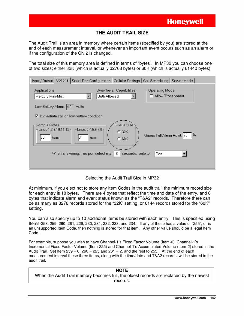
www.honeywell.com 142
THE AUDIT TRAIL SIZE
The Audit Trail is an area in memory where certain items (specified by you) are stored at the end of each measurement interval, or whenever an important event occurs such as an alarm or if the configuration of the CNI2 is changed. The total size of this memory area is defined in terms of “bytes”. In MP32 you can choose one of two sizes; either 32K (which is actually 32768 bytes) or 60K (which is actually 61440 bytes).
Selecting the Audit Trail Size in MP32 At minimum, if you elect not to store any Item Codes in the audit trail, the minimum record size for each entry is 10 bytes. There are 4 bytes that reflect the time and date of the entry, and 6 bytes that indicate alarm and event status known as the “T&A2” records. Therefore there can be as many as 3276 records stored for the “32K” setting, or 6144 records stored for the “60K” setting. You can also specify up to 10 additional Items be stored with each entry. This is specified using Items-258, 259, 260, 261, 229, 230, 231, 232, 233, and 234. If any of these has a value of “255”, or is an unsupported Item Code, then nothing is stored for that item. Any other value should be a legal Item Code. For example, suppose you wish to have Channel-1’s Fixed Factor Volume (Item-0), Channel-1’s Incremental Fixed Factor Volume (Item-225) and Channel-1’s Accumulated Volume (Item-2) stored in the Audit Trail. Set Item 259 = 0, 260 = 225 and 261 = 2, and the rest to 255. At the end of each measurement interval these three items, along with the time/date and T&A2 records, will be stored in the audit trail.
NOTE
When the Audit Trail memory becomes full, the oldest records are replaced by the newest records.
www.honeywell.com 143
Each additional item to be stored occupies 8 bytes each. So in our example we have time/date (4 bytes), three other items (3 x 8 = 24 bytes) and the T&A2 records (6 bytes), for a total of 34 bytes per entry. Therefore there can be as many as 963 records stored for the “32K” setting, or 1807 records stored for the “60K” setting. The maximum record size is reported in Item-481. It is recalculated any time something is added to or removed from the list of things to be recorded.
WARNING Any time the Audit Trail configuration is changed, the Audit Trail is cleared and all previous
records will be lost.
THE “T&A” AND “T&A2” EVENT RECORDS
The “T&A” and “T&A2” records, which are stored in the audit trail, are used to report certain events as they occur. Many of the individual event and alarm bits in these records are associated with pressure and temperature, neither of which is measured by the CNI2. The legacy “T&A2” record consists of 24 bits of information. The bits are labeled as follows:
ABCD EFGH IJKL MNOP QRST WXYZ The legacy “T&A” record consists of 16 bits of information. The bits are labeled as follows:
ABCD MNOP QRST WXYZ Bits ABCD indicate the reason that an entry was made into the audit trail: 0000 – Scheduled entry (usually the end of a pulse-counting interval) 0010 – Entry made due to an alarm condition. 0011 – Entry made due to an access from the serial port (usually done with MasterLink). 0111 – Entry made because some item was changed. 1000 – Entry made because the CNI2 was reset 1001 – Entry made because an alarm condition was cleared by command Bits EFGH and IJKL are not currently used. Bits MNOP, QRST and WXYZ are used to indicate a specific alarm condition: Bit-M: The 2nd CNI2 input configured as an ALARM input has gone active. Bit-N: The 1st CNI2 input configured as an ALARM input has gone active. Bit-O: Not currently used, Bit-P: The 5th CNI2 input configured as an ALARM input has gone active. Bit-Q: The 4th CNI2 input configured as an ALARM input has gone active. Bit-R: The 3rd CNI2 input configured as an ALARM input has gone active. Bit-S: Not currently used, Bit-T: Not currently used, Bit-W: Not currently used, Bit-X: Not currently used,
www.honeywell.com 144
Bit-Y: Primary power source has failed. Bit-Z: Low battery alarm Any of the CNI2’s input lines can be configured as alarm inputs, and those alarms can be configured to trigger a call into the host system. If any alarm input goes active an “ALARM TRIGGER” entry will be made in the Audit Trail and Item-108 will be set to a true condition. In addition the very first 5 inputs that are configured as ALARM inputs will set unique bits in the T&A2 or T&A records.
NOTE Some data collection systems may have different descriptions for some of the alarm bits.
In many cases these descriptions can be changed.
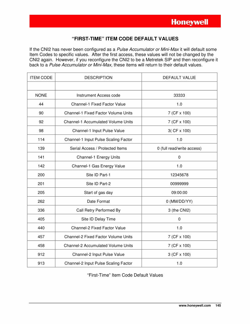
www.honeywell.com 145
“FIRST-TIME” ITEM CODE DEFAULT VALUES
If the CNI2 has never been configured as a Pulse Accumulator or Mini-Max it will default some Item Codes to specific values. After the first access, these values will not be changed by the CNI2 again. However, if you reconfigure the CNI2 to be a Metretek SIP and then reconfigure it back to a Pulse Accumulator or Mini-Max, these items will return to their default values.
ITEM CODE DESCRIPTION DEFAULT VALUE
NONE Instrument Access code 33333
44 Channel-1 Fixed Factor Value 1.0
90 Channel-1 Fixed Factor Volume Units 7 (CF x 100)
92 Channel-1 Accumulated Volume Units 7 (CF x 100)
98 Channel-1 Input Pulse Value 3( CF x 100)
114 Channel-1 Input Pulse Scaling Factor 1.0
139 Serial Access / Protected Items 0 (full read/write access)
141 Channel-1 Energy Units 0
142 Channel-1 Gas Energy Value 1.0
200 Site ID Part-1 12345678
201 Site ID Part-2 00999999
205 Start of gas day 09:00:00
262 Date Format 0 (MM/DD/YY)
336 Call Retry Performed By 3 (the CNI2)
405 Site ID Delay Time 0
440 Channel-2 Fixed Factor Value 1.0
457 Channel-2 Fixed Factor Volume Units 7 (CF x 100)
458 Channel-2 Accumulated Volume Units 7 (CF x 100)
912 Channel-2 Input Pulse Value 3 (CF x 100)
913 Channel-2 Input Pulse Scaling Factor 1.0
“First-Time” Item Code Default Values
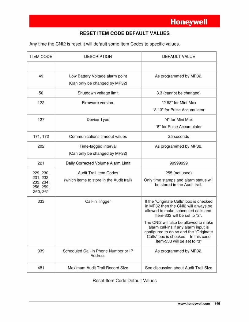
www.honeywell.com 146
RESET ITEM CODE DEFAULT VALUES
Any time the CNI2 is reset it will default some Item Codes to specific values.
ITEM CODE DESCRIPTION DEFAULT VALUE
49 Low Battery Voltage alarm point
(Can only be changed by MP32)
As programmed by MP32.
50 Shutdown voltage limit 3.3 (cannot be changed)
122 Firmware version. “2.82” for Mini-Max
“3.13” for Pulse Accumulator
127 Device Type “4” for Mini Max
“8” for Pulse Accumulator
171, 172 Communications timeout values 25 seconds
202 Time-tagged interval
(Can only be changed by MP32)
As programmed by MP32.
221 Daily Corrected Volume Alarm Limit 99999999
229, 230, 231, 232, 233, 234, 258, 259, 260, 261
Audit Trail Item Codes
(which items to store in the Audit trail)
255 (not used)
Only time stamps and alarm status will be stored in the Audit trail.
333 Call-in Trigger If the “Originate Calls” box is checked in MP32 then the CNI2 will always be allowed to make scheduled calls and.
Item-333 will be set to “2”.
The CNI2 will also be allowed to make alarm call-ins if any alarm input is
configured to do so and the “Originate Calls” box is checked. In this case
Item-333 will be set to “3”
339 Scheduled Call-in Phone Number or IP Address
As programmed by MP32.
481 Maximum Audit Trail Record Size See discussion about Audit Trail Size
Reset Item Code Default Values
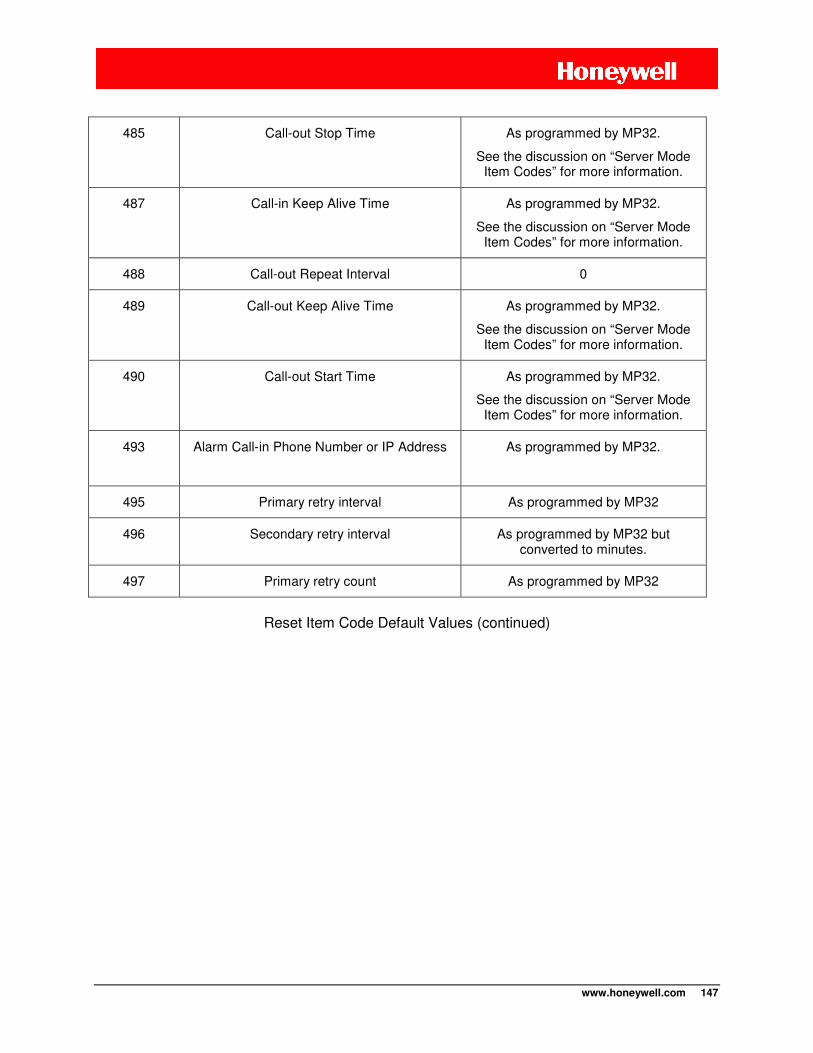
www.honeywell.com 147
485 Call-out Stop Time As programmed by MP32.
See the discussion on “Server Mode Item Codes” for more information.
487 Call-in Keep Alive Time As programmed by MP32.
See the discussion on “Server Mode Item Codes” for more information.
488 Call-out Repeat Interval 0
489 Call-out Keep Alive Time As programmed by MP32.
See the discussion on “Server Mode Item Codes” for more information.
490 Call-out Start Time As programmed by MP32.
See the discussion on “Server Mode Item Codes” for more information.
493 Alarm Call-in Phone Number or IP Address As programmed by MP32.
495 Primary retry interval As programmed by MP32
496 Secondary retry interval As programmed by MP32 but converted to minutes.
497 Primary retry count As programmed by MP32
Reset Item Code Default Values (continued)
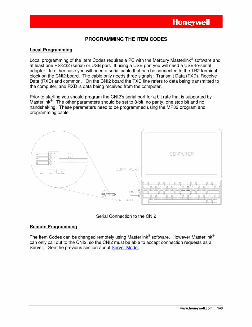
www.honeywell.com 148
PROGRAMMING THE ITEM CODES
Local Programming
Local programming of the Item Codes requires a PC with the Mercury Masterlink® software and at least one RS-232 (serial) or USB port. If using a USB port you will need a USB-to-serial adapter. In either case you will need a serial cable that can be connected to the TB2 terminal block on the CNI2 board. The cable only needs three signals: Transmit Data (TXD), Receive Data (RXD) and common. On the CNI2 board the TXD line refers to data being transmitted to the computer, and RXD is data being received from the computer. Prior to starting you should program the CNI2’s serial port for a bit rate that is supported by Masterlink®. The other parameters should be set to 8-bit, no parity, one stop bit and no handshaking. These parameters need to be programmed using the MP32 program and programming cable.
Serial Connection to the CNI2
Remote Programming The Item Codes can be changed remotely using Masterlink® software. However Masterlink® can only call out to the CNI2, so the CNI2 must be able to accept connection requests as a Server. See the previous section about Server Mode.
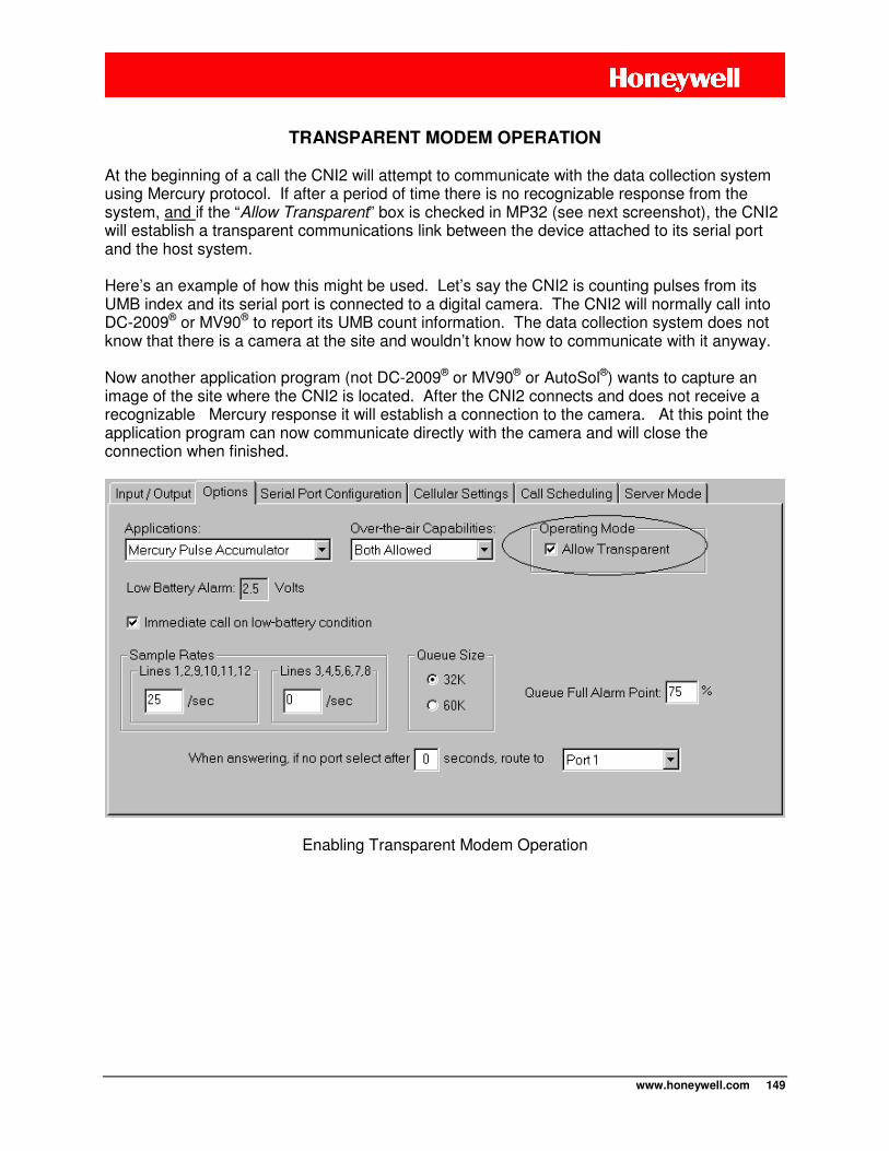
www.honeywell.com 149
TRANSPARENT MODEM OPERATION
At the beginning of a call the CNI2 will attempt to communicate with the data collection system using Mercury protocol. If after a period of time there is no recognizable response from the system, and if the “Allow Transparent” box is checked in MP32 (see next screenshot), the CNI2 will establish a transparent communications link between the device attached to its serial port and the host system. Here’s an example of how this might be used. Let’s say the CNI2 is counting pulses from its UMB index and its serial port is connected to a digital camera. The CNI2 will normally call into DC-2009® or MV90® to report its UMB count information. The data collection system does not know that there is a camera at the site and wouldn’t know how to communicate with it anyway. Now another application program (not DC-2009® or MV90® or AutoSol®) wants to capture an image of the site where the CNI2 is located. After the CNI2 connects and does not receive a recognizable Mercury response it will establish a connection to the camera. At this point the application program can now communicate directly with the camera and will close the connection when finished.
Enabling Transparent Modem Operation

www.honeywell.com 150
The time it takes to establish the transparent connection might be 50 seconds or more. There is an Item Codes that affects this delay period.
1) If the CNI2 is originating the call into the host system it sends a particular message to the host and must wait up to 20 seconds to receive a response from the host system. This is a fixed time period that cannot be changed.
2) Whether calling in to the host system or answering a call from the host system, the CNI2 must wait for a particular message from the host system. The amount of time to wait is defined by Item-171. The default value is 25 seconds but you can make this shorter. Do not make this shorter than 10 seconds otherwise latency delays in the cellular network may cause a call to terminate early.
If the CNI2 has not received a recognizable response from the system the Transparent Mode will be entered. For more information on Transparent Modem operation see the section entitled “Allow Transparent Mode”.
www.honeywell.com 151
NOTE
“Power Preservation Mode” is available with firmware version V1.4 or later.
“Power Preservation Mode” becomes important when the CNI2 has a primary power source such as an ac-to-dc power adapter, and also a backup power source such as a battery. If ac power is lost the backup battery will allow the CNI2 to continue to count pulses, monitor alarms, keep time, etc. However the battery may not be able to support full-time radio operations for very long. “Power Preservation Mode” allows the CNI2 to temporarily suspend full-time radio operations in favor of preserving pulse-counting and time-keeping operations.
NOTE
The CNI2 always draws power from the highest voltage source. Therefore the primary power source should always be a higher voltage than the backup supply.
EXAMPLE
The CNI2 has been configured as a data logger and to respond to SMS (text) messages as a paging mechanism. This requires the radio to be powered up at all times to receive those messages. The CNI2 is connected to a 9Vdc ac-to-dc power adapter, and also a small 7.2Vdc lithium backup battery that can only support two full hours of continuous radio operations. The ac power grid goes down for 4 hours. Without “Power Preservation Mode” the CNI2 would continue as though nothing had happened. The lithium battery dies after 2 hours and all pulse and time information is lost. With “Power Preservation Mode” the radio is powered down during the time that ac power is lost. After ac power is restored the radio is turned back on and normal operation resumes. There is little impact to the lithium backup battery and no data is lost. There is however a 4-hour window in which the CNI2 cannot be paged.
POWER PRESERVATION MODE
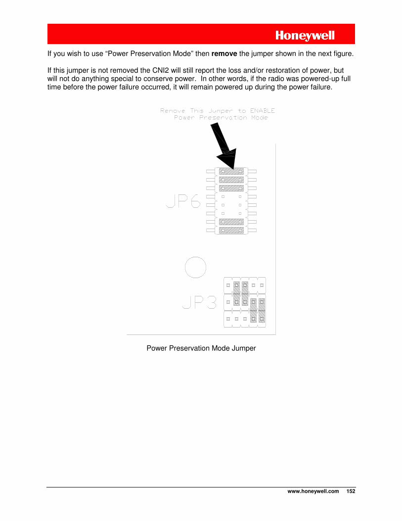
www.honeywell.com 152
If you wish to use “Power Preservation Mode” then remove the jumper shown in the next figure. If this jumper is not removed the CNI2 will still report the loss and/or restoration of power, but will not do anything special to conserve power. In other words, if the radio was powered-up full time before the power failure occurred, it will remain powered up during the power failure.
Power Preservation Mode Jumper
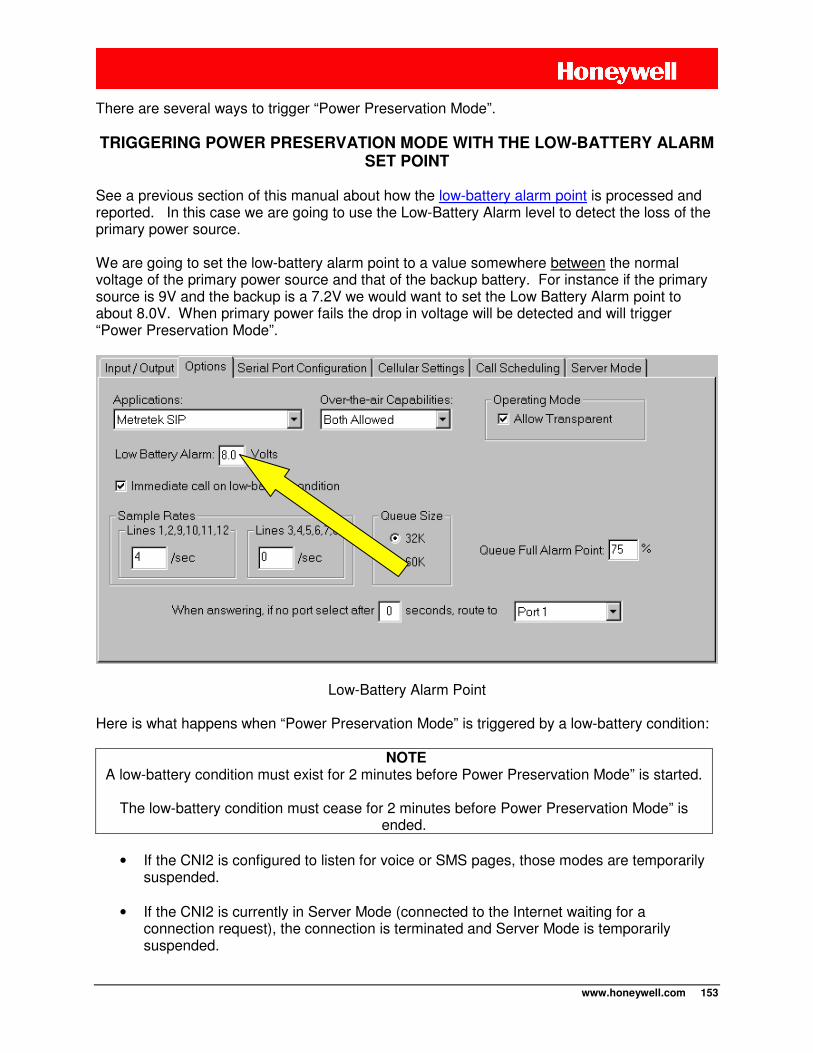
www.honeywell.com 153
There are several ways to trigger “Power Preservation Mode”. TRIGGERING POWER PRESERVATION MODE WITH THE LOW-BATTERY ALARM
SET POINT See a previous section of this manual about how the low-battery alarm point is processed and reported. In this case we are going to use the Low-Battery Alarm level to detect the loss of the primary power source. We are going to set the low-battery alarm point to a value somewhere between the normal voltage of the primary power source and that of the backup battery. For instance if the primary source is 9V and the backup is a 7.2V we would want to set the Low Battery Alarm point to about 8.0V. When primary power fails the drop in voltage will be detected and will trigger “Power Preservation Mode”.
Low-Battery Alarm Point Here is what happens when “Power Preservation Mode” is triggered by a low-battery condition:
NOTE
A low-battery condition must exist for 2 minutes before Power Preservation Mode” is started.
The low-battery condition must cease for 2 minutes before Power Preservation Mode” is ended.
• If the CNI2 is configured to listen for voice or SMS pages, those modes are temporarily
suspended.
• If the CNI2 is currently in Server Mode (connected to the Internet waiting for a connection request), the connection is terminated and Server Mode is temporarily suspended.
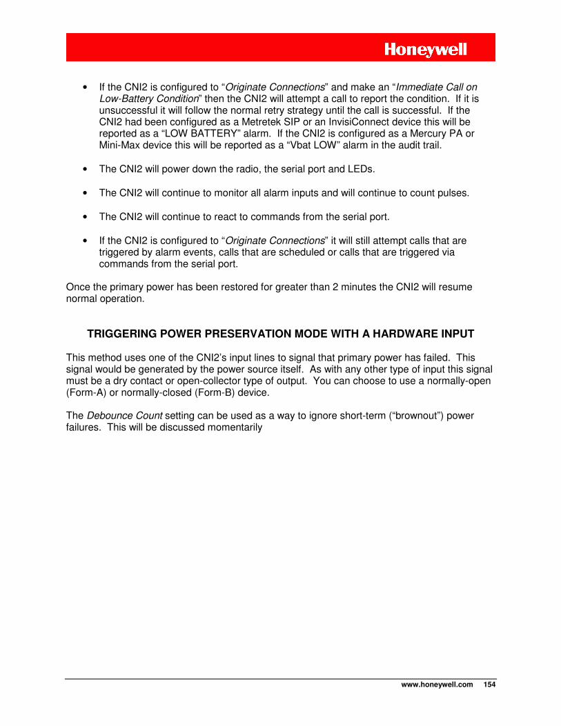
www.honeywell.com 154
• If the CNI2 is configured to “Originate Connections” and make an “Immediate Call on
Low-Battery Condition” then the CNI2 will attempt a call to report the condition. If it is unsuccessful it will follow the normal retry strategy until the call is successful. If the CNI2 had been configured as a Metretek SIP or an InvisiConnect device this will be reported as a “LOW BATTERY” alarm. If the CNI2 is configured as a Mercury PA or Mini-Max device this will be reported as a “Vbat LOW” alarm in the audit trail.
• The CNI2 will power down the radio, the serial port and LEDs.
• The CNI2 will continue to monitor all alarm inputs and will continue to count pulses.
• The CNI2 will continue to react to commands from the serial port.
• If the CNI2 is configured to “Originate Connections” it will still attempt calls that are
triggered by alarm events, calls that are scheduled or calls that are triggered via commands from the serial port.
Once the primary power has been restored for greater than 2 minutes the CNI2 will resume normal operation.
TRIGGERING POWER PRESERVATION MODE WITH A HARDWARE INPUT This method uses one of the CNI2’s input lines to signal that primary power has failed. This signal would be generated by the power source itself. As with any other type of input this signal must be a dry contact or open-collector type of output. You can choose to use a normally-open (Form-A) or normally-closed (Form-B) device. The Debounce Count setting can be used as a way to ignore short-term (“brownout”) power failures. This will be discussed momentarily
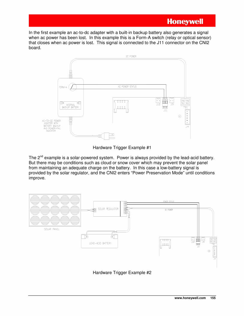
www.honeywell.com 155
In the first example an ac-to-dc adapter with a built-in backup battery also generates a signal when ac power has been lost. In this example this is a Form-A switch (relay or optical sensor) that closes when ac power is lost. This signal is connected to the J11 connector on the CNI2 board.
Hardware Trigger Example #1 The 2nd example is a solar-powered system. Power is always provided by the lead-acid battery. But there may be conditions such as cloud or snow cover which may prevent the solar panel from maintaining an adequate charge on the battery. In this case a low-battery signal is provided by the solar regulator, and the CNI2 enters “Power Preservation Mode” until conditions improve.
Hardware Trigger Example #2
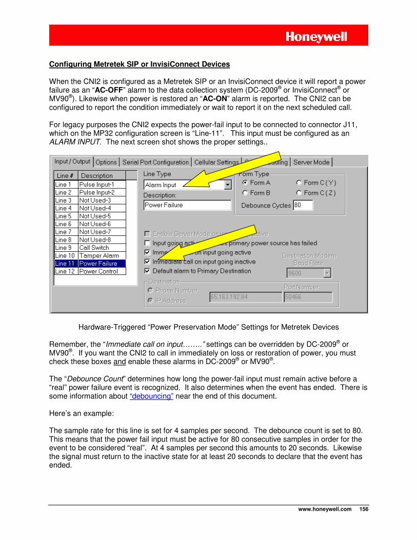
www.honeywell.com 156
Configuring Metretek SIP or InvisiConnect Devices When the CNI2 is configured as a Metretek SIP or an InvisiConnect device it will report a power failure as an “AC-OFF” alarm to the data collection system (DC-2009® or InvisiConnect® or MV90®). Likewise when power is restored an “AC-ON” alarm is reported. The CNI2 can be configured to report the condition immediately or wait to report it on the next scheduled call. For legacy purposes the CNI2 expects the power-fail input to be connected to connector J11, which on the MP32 configuration screen is “Line-11”. This input must be configured as an ALARM INPUT. The next screen shot shows the proper settings..
Hardware-Triggered “Power Preservation Mode” Settings for Metretek Devices Remember, the “Immediate call on input……..” settings can be overridden by DC-2009® or MV90®. If you want the CNI2 to call in immediately on loss or restoration of power, you must check these boxes and enable these alarms in DC-2009® or MV90®. The “Debounce Count” determines how long the power-fail input must remain active before a “real” power failure event is recognized. It also determines when the event has ended. There is some information about “debouncing” near the end of this document. Here’s an example: The sample rate for this line is set for 4 samples per second. The debounce count is set to 80. This means that the power fail input must be active for 80 consecutive samples in order for the event to be considered “real”. At 4 samples per second this amounts to 20 seconds. Likewise the signal must return to the inactive state for at least 20 seconds to declare that the event has ended.
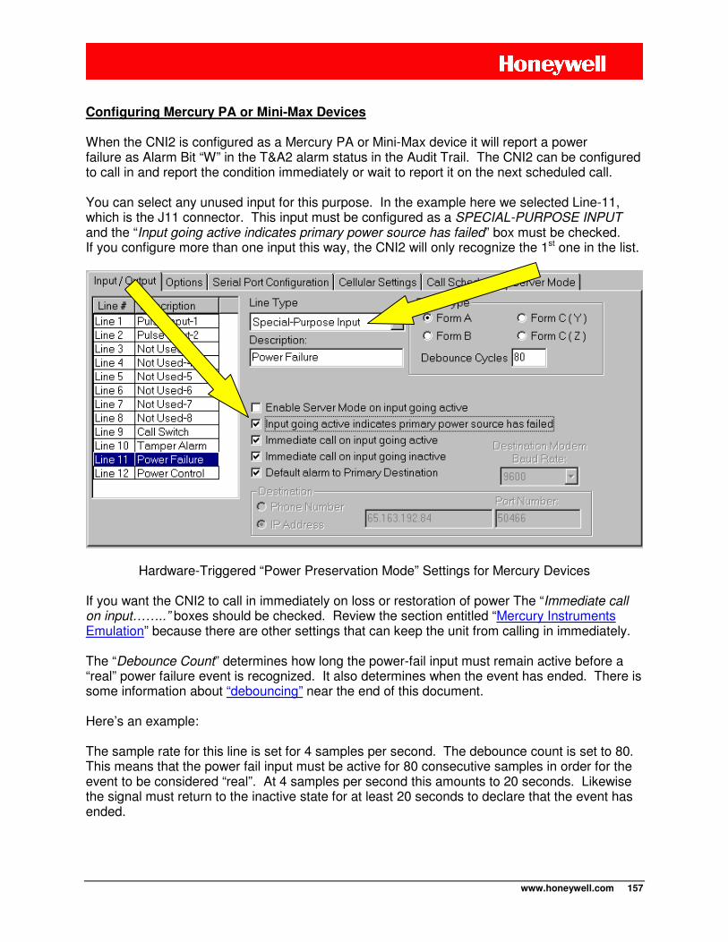
www.honeywell.com 157
Configuring Mercury PA or Mini-Max Devices When the CNI2 is configured as a Mercury PA or Mini-Max device it will report a power failure as Alarm Bit “W” in the T&A2 alarm status in the Audit Trail. The CNI2 can be configured to call in and report the condition immediately or wait to report it on the next scheduled call. You can select any unused input for this purpose. In the example here we selected Line-11, which is the J11 connector. This input must be configured as a SPECIAL-PURPOSE INPUT and the “Input going active indicates primary power source has failed” box must be checked. If you configure more than one input this way, the CNI2 will only recognize the 1st one in the list.
Hardware-Triggered “Power Preservation Mode” Settings for Mercury Devices If you want the CNI2 to call in immediately on loss or restoration of power The “Immediate call on input……..” boxes should be checked. Review the section entitled “Mercury Instruments Emulation” because there are other settings that can keep the unit from calling in immediately. The “Debounce Count” determines how long the power-fail input must remain active before a “real” power failure event is recognized. It also determines when the event has ended. There is some information about “debouncing” near the end of this document. Here’s an example: The sample rate for this line is set for 4 samples per second. The debounce count is set to 80. This means that the power fail input must be active for 80 consecutive samples in order for the event to be considered “real”. At 4 samples per second this amounts to 20 seconds. Likewise the signal must return to the inactive state for at least 20 seconds to declare that the event has ended.
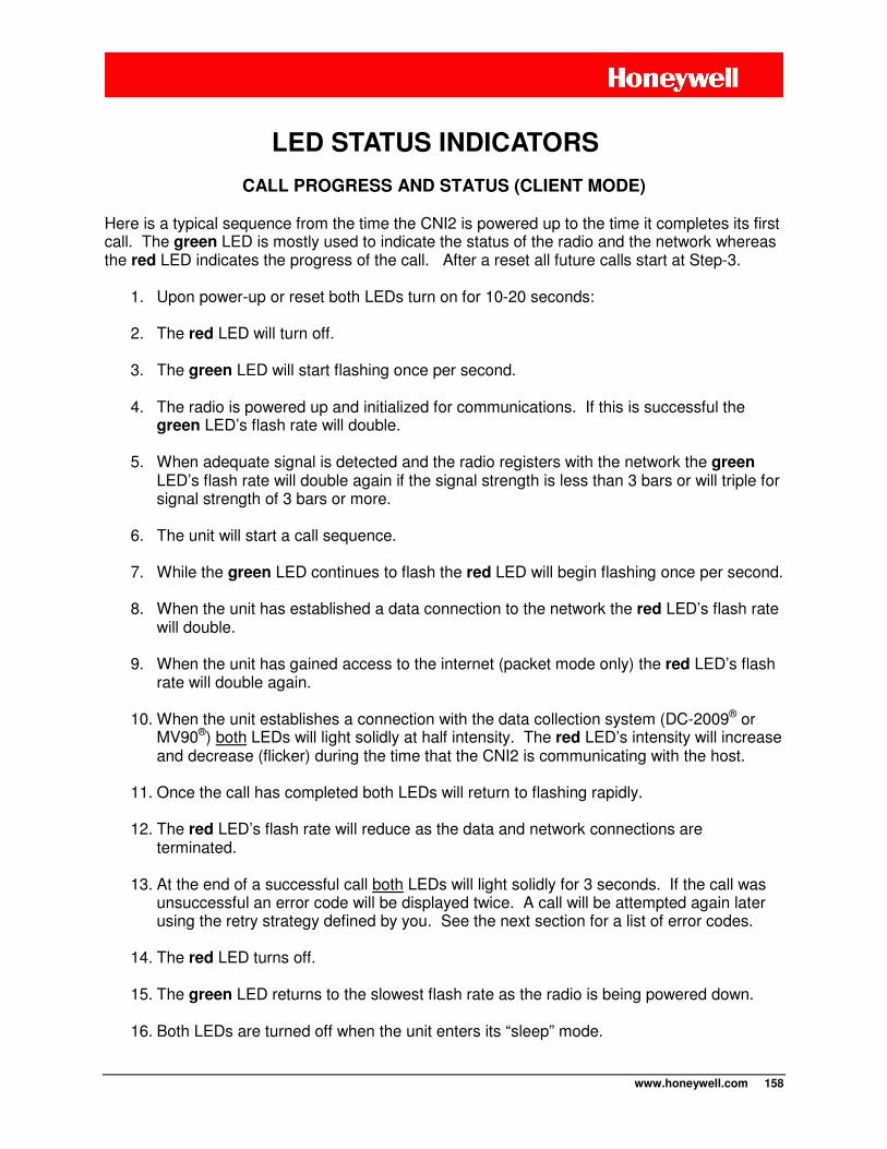
www.honeywell.com 158
CALL PROGRESS AND STATUS (CLIENT MODE)
Here is a typical sequence from the time the CNI2 is powered up to the time it completes its first call. The green LED is mostly used to indicate the status of the radio and the network whereas the red LED indicates the progress of the call. After a reset all future calls start at Step-3.
1. Upon power-up or reset both LEDs turn on for 10-20 seconds:
2. The red LED will turn off.
3. The green LED will start flashing once per second.
4. The radio is powered up and initialized for communications. If this is successful the green LED’s flash rate will double.
5. When adequate signal is detected and the radio registers with the network the green
LED’s flash rate will double again if the signal strength is less than 3 bars or will triple for signal strength of 3 bars or more.
6. The unit will start a call sequence.
7. While the green LED continues to flash the red LED will begin flashing once per second.
8. When the unit has established a data connection to the network the red LED’s flash rate
will double.
9. When the unit has gained access to the internet (packet mode only) the red LED’s flash rate will double again.
10. When the unit establishes a connection with the data collection system (DC-2009® or
MV90®) both LEDs will light solidly at half intensity. The red LED’s intensity will increase and decrease (flicker) during the time that the CNI2 is communicating with the host.
11. Once the call has completed both LEDs will return to flashing rapidly.
12. The red LED’s flash rate will reduce as the data and network connections are
terminated.
13. At the end of a successful call both LEDs will light solidly for 3 seconds. If the call was unsuccessful an error code will be displayed twice. A call will be attempted again later using the retry strategy defined by you. See the next section for a list of error codes.
14. The red LED turns off.
15. The green LED returns to the slowest flash rate as the radio is being powered down.
16. Both LEDs are turned off when the unit enters its “sleep” mode.
LED STATUS INDICATORS
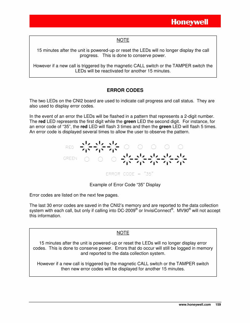
www.honeywell.com 159
ERROR CODES
The two LEDs on the CNI2 board are used to indicate call progress and call status. They are also used to display error codes. In the event of an error the LEDs will be flashed in a pattern that represents a 2-digit number. The red LED represents the first digit while the green LED the second digit. For instance, for an error code of “35”, the red LED will flash 3 times and then the green LED will flash 5 times. An error code is displayed several times to allow the user to observe the pattern.
Example of Error Code “35” Display
Error codes are listed on the next few pages. The last 30 error codes are saved in the CNI2’s memory and are reported to the data collection system with each call, but only if calling into DC-2009® or InvisiConnect®. MV90® will not accept this information.
NOTE
15 minutes after the unit is powered-up or reset the LEDs will no longer display the call progress. This is done to conserve power.
However if a new call is triggered by the magnetic CALL switch or the TAMPER switch the
LEDs will be reactivated for another 15 minutes.
NOTE
15 minutes after the unit is powered-up or reset the LEDs will no longer display error codes. This is done to conserve power. Errors that do occur will still be logged in memory
and reported to the data collection system.
However if a new call is triggered by the magnetic CALL switch or the TAMPER switch then new error codes will be displayed for another 15 minutes.
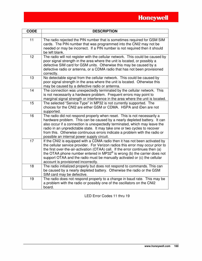
www.honeywell.com 160
CODE DESCRIPTION
11 The radio rejected the PIN number that is sometimes required for GSM SIM
cards. The PIN number that was programmed into the CNI2 may not be needed or may be incorrect. If a PIN number is not required then it should be left blank.
12 The radio will not register with the cellular network. This could be caused by poor signal strength in the area where the unit is located, or possibly a defective SIM card for GSM units. Otherwise this may be caused by a defective radio or antenna, or a CDMA radio that has not been provisioned correctly.
13 No detectable signal from the cellular network. This could be caused by poor signal strength in the area where the unit is located. Otherwise this may be caused by a defective radio or antenna.
14 The connection was unexpectedly terminated by the cellular network. This is not necessarily a hardware problem. Frequent errors may point to marginal signal strength or interference in the area where the unit is located.
15 The selected “Service Type” in MP32 is not currently supported. The choices for the CNI2 are either GSM or CDMA. HSPA and iDen are not supported.
16 The radio did not respond properly when reset. This is not necessarily a hardware problem. This can be caused by a nearly depleted battery. It can also occur if a connection is unexpectedly terminated, which may leave the radio in an unpredictable state. It may take one or two cycles to recover from this. Otherwise continuous errors indicate a problem with the radio or possible an internal power supply circuit.
17 If the CNI2 is equipped with a CDMA radio then it has not been activated by the cellular service provider. For Verizon radios this error may occur prior to the first over-the-air-activation (OTAA) call. If the error continues then (a) the OTAA phone number entered in MP32® is wrong (b) the carrier does not support OTAA and the radio must be manually activated or (c) the cellular account is provisioned incorrectly.
18 The radio initialized properly but does not respond to commands. This can be caused by a nearly depleted battery. Otherwise the radio or the GSM SIM card may be defective.
19 The radio does not respond properly to a change in baud rate. This may be a problem with the radio or possibly one of the oscillators on the CNI2 board.
LED Error Codes 11 thru 19
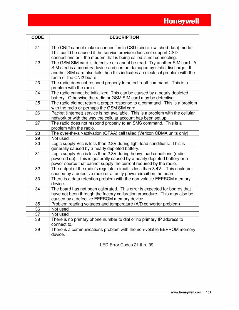
www.honeywell.com 161
CODE DESCRIPTION
21 The CNI2 cannot make a connection in CSD (circuit-switched-data) mode.
This could be caused if the service provider does not support CSD connections or if the modem that is being called is not connecting.
22 The GSM SIM card is defective or cannot be read. Try another SIM card. A SIM card is a memory device and can be damaged by static discharge. If another SIM card also fails then this indicates an electrical problem with the radio or the CNI2 board.
23 The radio does not respond properly to an echo-off command. This is a problem with the radio.
24 The radio cannot be initialized. This can be caused by a nearly depleted battery. Otherwise the radio or GSM SIM card may be defective.
25 The radio did not return a proper response to a command. This is a problem with the radio or perhaps the GSM SIM card.
26 Packet (Internet) service is not available. This is a problem with the cellular network or with the way the cellular account has been set up.
27 The radio does not respond properly to an SMS command. This is a problem with the radio.
28 The over-the-air-activation (OTAA) call failed (Verizon CDMA units only) 29 Not used 30 Logic supply Vcc is less than 2.8V during light-load conditions. This is
generally caused by a nearly depleted battery. 31 Logic supply Vcc is less than 2.8V during heavy-load conditions (radio
powered up). This is generally caused by a nearly depleted battery or a power source that cannot supply the current required by the radio.
32 The output of the radio’s regulator circuit is less than 3.4V. This could be caused by a defective radio or a faulty power circuit on the board.
33 There is a data retention problem with the non-volatile EEPROM memory device.
34 The board has not been calibrated. This error is expected for boards that have not been through the factory calibration procedure. This may also be caused by a defective EEPROM memory device.
35 Problem reading voltages and temperature (A/D converter problem) 36 Not used 37 Not used 38 There is no primary phone number to dial or no primary IP address to
connect to. 39 There is a communications problem with the non-volatile EEPROM memory
device.
LED Error Codes 21 thru 39
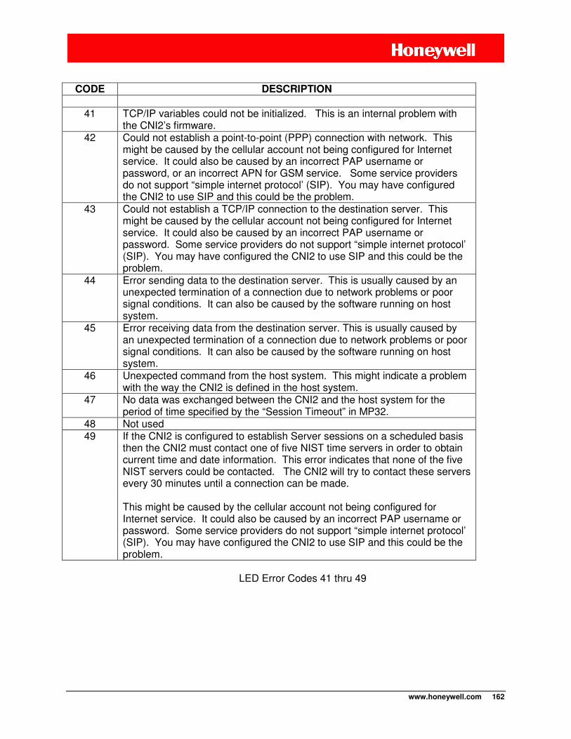
www.honeywell.com 162
CODE DESCRIPTION
41 TCP/IP variables could not be initialized. This is an internal problem with
the CNI2’s firmware. 42 Could not establish a point-to-point (PPP) connection with network. This
might be caused by the cellular account not being configured for Internet service. It could also be caused by an incorrect PAP username or password, or an incorrect APN for GSM service. Some service providers do not support “simple internet protocol’ (SIP). You may have configured the CNI2 to use SIP and this could be the problem.
43 Could not establish a TCP/IP connection to the destination server. This might be caused by the cellular account not being configured for Internet service. It could also be caused by an incorrect PAP username or password. Some service providers do not support “simple internet protocol’ (SIP). You may have configured the CNI2 to use SIP and this could be the problem.
44 Error sending data to the destination server. This is usually caused by an unexpected termination of a connection due to network problems or poor signal conditions. It can also be caused by the software running on host system.
45 Error receiving data from the destination server. This is usually caused by an unexpected termination of a connection due to network problems or poor signal conditions. It can also be caused by the software running on host system.
46 Unexpected command from the host system. This might indicate a problem with the way the CNI2 is defined in the host system.
47 No data was exchanged between the CNI2 and the host system for the period of time specified by the “Session Timeout” in MP32.
48 Not used 49 If the CNI2 is configured to establish Server sessions on a scheduled basis
then the CNI2 must contact one of five NIST time servers in order to obtain current time and date information. This error indicates that none of the five NIST servers could be contacted. The CNI2 will try to contact these servers every 30 minutes until a connection can be made. This might be caused by the cellular account not being configured for Internet service. It could also be caused by an incorrect PAP username or password. Some service providers do not support “simple internet protocol’ (SIP). You may have configured the CNI2 to use SIP and this could be the problem.
LED Error Codes 41 thru 49
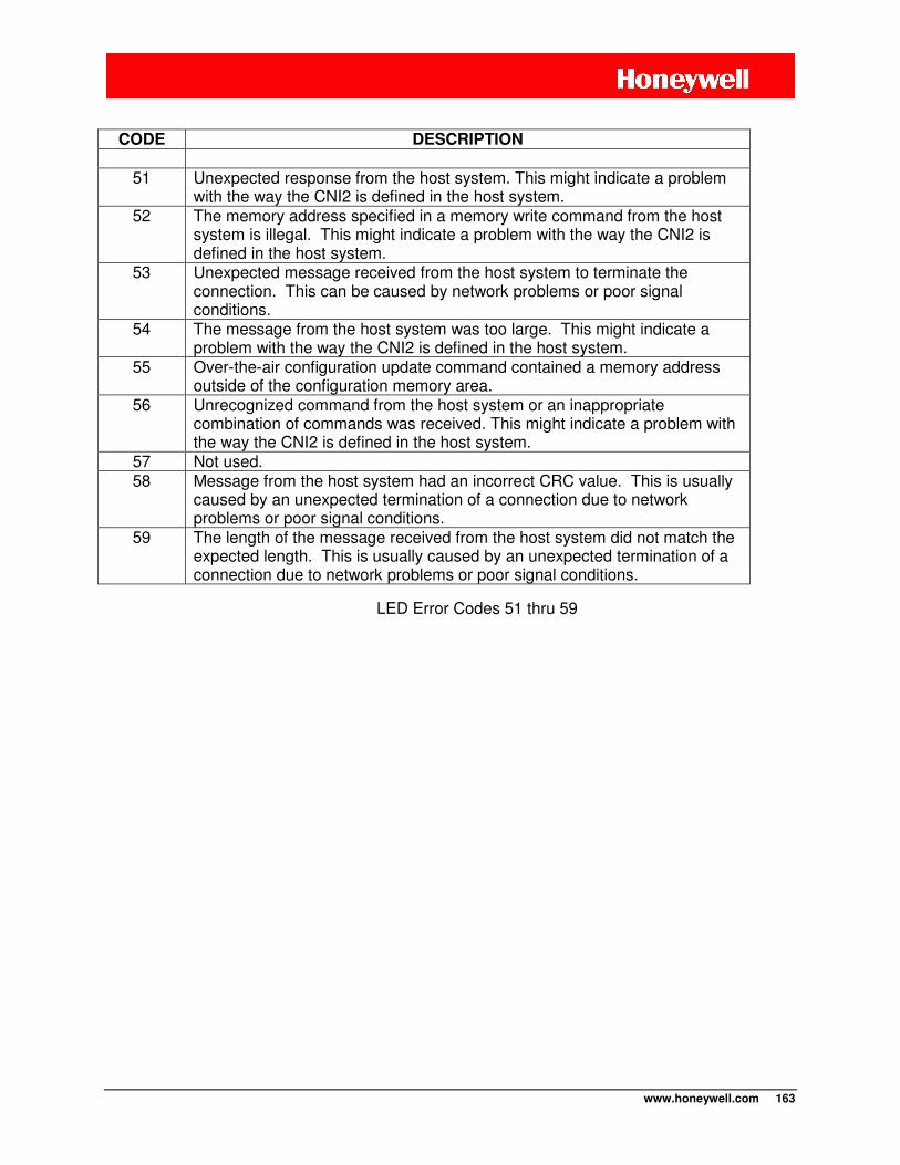
www.honeywell.com 163
CODE DESCRIPTION
51 Unexpected response from the host system. This might indicate a problem
with the way the CNI2 is defined in the host system. 52 The memory address specified in a memory write command from the host
system is illegal. This might indicate a problem with the way the CNI2 is defined in the host system.
53 Unexpected message received from the host system to terminate the connection. This can be caused by network problems or poor signal conditions.
54 The message from the host system was too large. This might indicate a problem with the way the CNI2 is defined in the host system.
55 Over-the-air configuration update command contained a memory address outside of the configuration memory area.
56 Unrecognized command from the host system or an inappropriate combination of commands was received. This might indicate a problem with the way the CNI2 is defined in the host system.
57 Not used. 58 Message from the host system had an incorrect CRC value. This is usually
caused by an unexpected termination of a connection due to network problems or poor signal conditions.
59 The length of the message received from the host system did not match the expected length. This is usually caused by an unexpected termination of a connection due to network problems or poor signal conditions.
LED Error Codes 51 thru 59
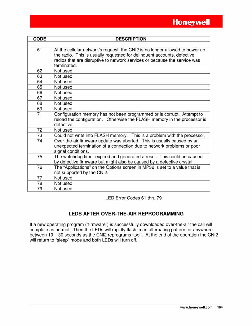
www.honeywell.com 164
CODE DESCRIPTION
61 At the cellular network’s request, the CNI2 is no longer allowed to power up the radio. This is usually requested for delinquent accounts, defective radios that are disruptive to network services or because the service was terminated.
62 Not used 63 Not used 64 Not used 65 Not used 66 Not used 67 Not used 68 Not used 69 Not used 71 Configuration memory has not been programmed or is corrupt. Attempt to
reload the configuration. Otherwise the FLASH memory in the processor is defective.
72 Not used 73 Could not write into FLASH memory. This is a problem with the processor. 74 Over-the-air firmware update was aborted. This is usually caused by an
unexpected termination of a connection due to network problems or poor signal conditions.
75 The watchdog timer expired and generated a reset. This could be caused by defective firmware but might also be caused by a defective crystal.
76 The “Applications” on the Options screen in MP32 is set to a value that is not supported by the CNI2.
77 Not used 78 Not used 79 Not used
LED Error Codes 61 thru 79
LEDS AFTER OVER-THE-AIR REPROGRAMMING
If a new operating program (“firmware”) is successfully downloaded over-the-air the call will complete as normal. Then the LEDs will rapidly flash in an alternating pattern for anywhere between 10 – 30 seconds as the CNI2 reprograms itself. At the end of the operation the CNI2 will return to “sleep” mode and both LEDs will turn off.
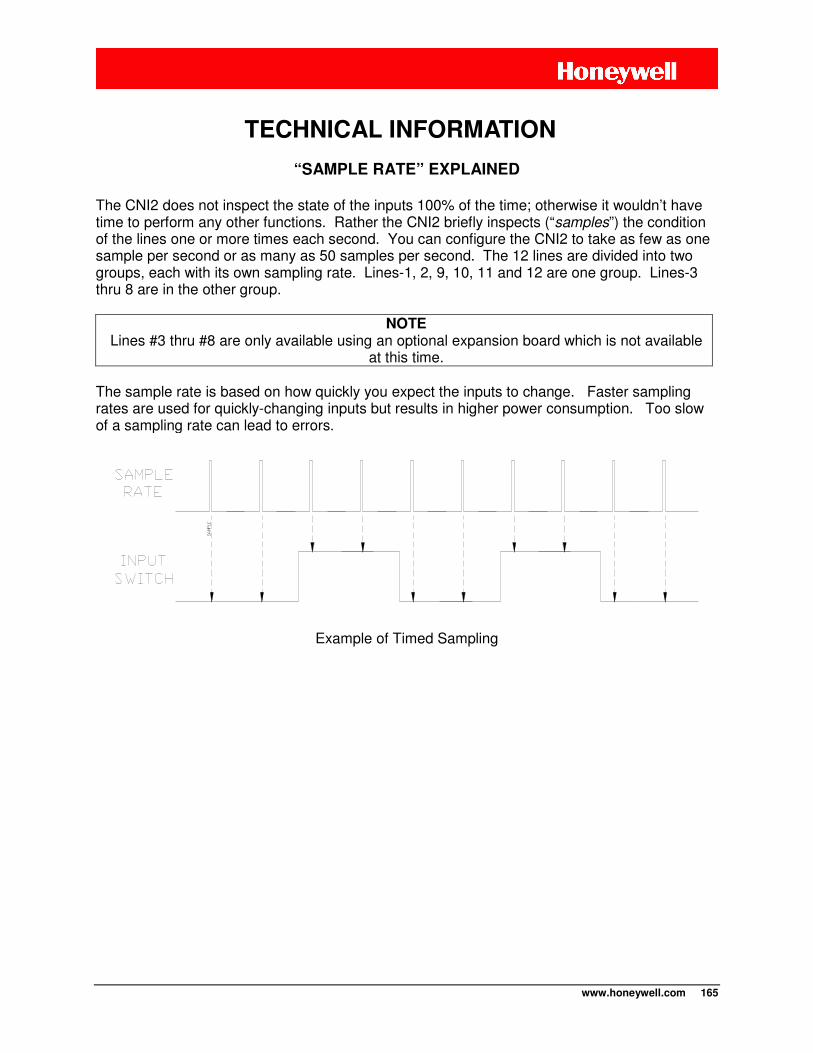
www.honeywell.com 165
“SAMPLE RATE” EXPLAINED
The CNI2 does not inspect the state of the inputs 100% of the time; otherwise it wouldn’t have time to perform any other functions. Rather the CNI2 briefly inspects (“samples”) the condition of the lines one or more times each second. You can configure the CNI2 to take as few as one sample per second or as many as 50 samples per second. The 12 lines are divided into two groups, each with its own sampling rate. Lines-1, 2, 9, 10, 11 and 12 are one group. Lines-3 thru 8 are in the other group.
NOTE Lines #3 thru #8 are only available using an optional expansion board which is not available
at this time. The sample rate is based on how quickly you expect the inputs to change. Faster sampling rates are used for quickly-changing inputs but results in higher power consumption. Too slow of a sampling rate can lead to errors.
Example of Timed Sampling
TECHNICAL INFORMATION

www.honeywell.com 166
“DEBOUNCE” EXPLAINED
What is Switch “Bounce”?
If you strike a hard surface with a stick it is likely to bounce a few times before coming to rest. The same is true for most mechanical switches. As the contacts come together they may “bounce” (open and close a few times), then finally settle in the closed position. This “bouncing” may be falsely interpreted as several events rather than just one. If the CNI2 is counting pulses from this switch it might interpret the bounce as two or three pulses rather than just one. Electronic switches such as transistors do not have this problem.
Example of Switch Bounce
What is “Debouncing”?
The process of “debouncing” requires the switch be in the same state over a specific number of samples to be considered “valid”. Therefore the DEBOUNCE CYCLES and SAMPLE RATE are interrelated. If the input line changes states within this period of time the event is ignored and the debouncing process starts over. See the next illustration. Suppose an alarm input is sampled 10 times a second and the debounce cycles are set for 4. This means that the input has to be in the same state for 4 consecutive samples (0.4 seconds) to be considered “valid”. If it changes even once during this time the entire process starts over. As seen in the illustration the first and second transitions were ignored because they did not stay in that same state for 4 samples. However the third transition was considered to be a “real” event. Setting the DEBOUNCE CYCLES to 1 will result in the fastest recognition of a change in the switch. As soon as it changes from one state to another it is considered “valid”. But this may also lead to inaccurate results if the switch bounces a lot. This setting is normally used with non-mechanical switches such as transistors because they do not exhibit bounce problems. The debounce cycle count can be as high as 255. The equation is (debounce ÷ sample rate) seconds. For instance if the sample rate is set to 25 and the debounce is 2, then the input condition will be recognized in (2 ÷ 25) seconds, or 0.08 seconds (80 mS). As an alarm input this means that the signal must be in the active (on) state for at least 80 mS to be considered a real alarm. As a pulse counting input the signal must be in the active (on) state for at least 80 mS and in the inactive (off) state for another 80 mS to be considered a real pulse. This total period of 160 mS translates into a maximum pulse rate of 6.25 pulses per second.
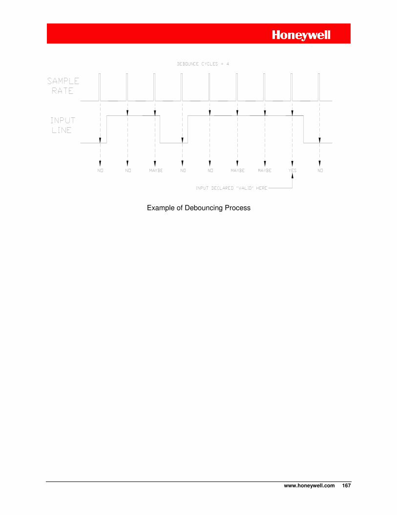
www.honeywell.com 167
Example of Debouncing Process
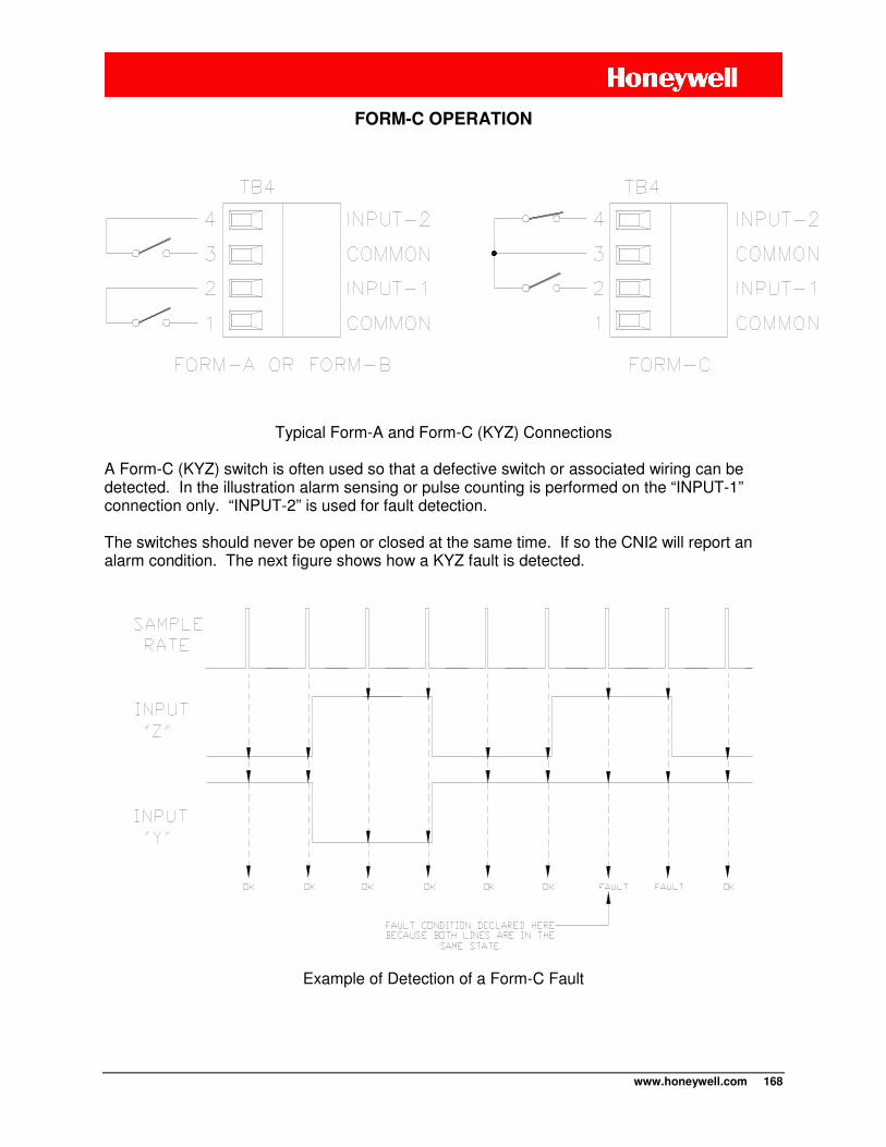
www.honeywell.com 168
FORM-C OPERATION
Typical Form-A and Form-C (KYZ) Connections
A Form-C (KYZ) switch is often used so that a defective switch or associated wiring can be detected. In the illustration alarm sensing or pulse counting is performed on the “INPUT-1” connection only. “INPUT-2” is used for fault detection. The switches should never be open or closed at the same time. If so the CNI2 will report an alarm condition. The next figure shows how a KYZ fault is detected.
Example of Detection of a Form-C Fault
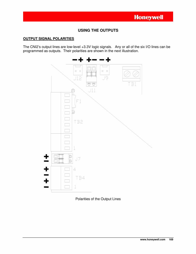
www.honeywell.com 169
USING THE OUTPUTS
OUTPUT SIGNAL POLARITIES The CNI2’s output lines are low-level +3.3V logic signals. Any or all of the six I/O lines can be programmed as outputs. Their polarities are shown in the next illustration.
Polarities of the Output Lines
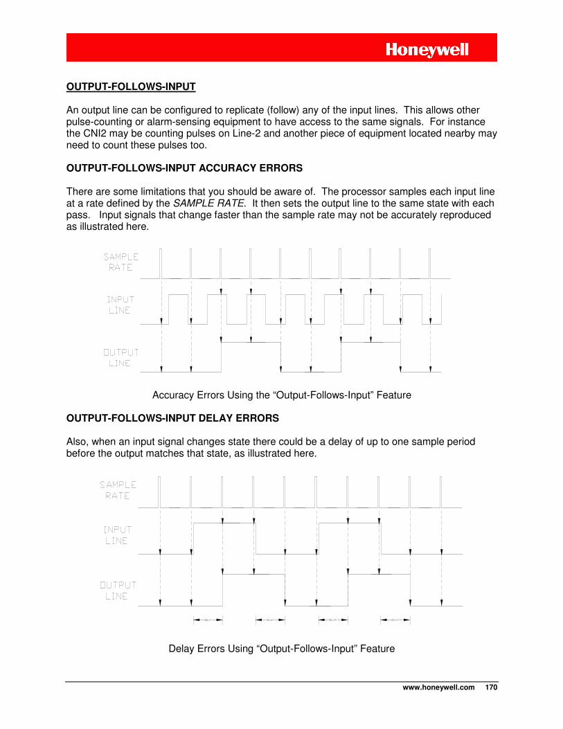
www.honeywell.com 170
OUTPUT-FOLLOWS-INPUT An output line can be configured to replicate (follow) any of the input lines. This allows other pulse-counting or alarm-sensing equipment to have access to the same signals. For instance the CNI2 may be counting pulses on Line-2 and another piece of equipment located nearby may need to count these pulses too. OUTPUT-FOLLOWS-INPUT ACCURACY ERRORS
There are some limitations that you should be aware of. The processor samples each input line at a rate defined by the SAMPLE RATE. It then sets the output line to the same state with each pass. Input signals that change faster than the sample rate may not be accurately reproduced as illustrated here.
Accuracy Errors Using the “Output-Follows-Input” Feature
OUTPUT-FOLLOWS-INPUT DELAY ERRORS
Also, when an input signal changes state there could be a delay of up to one sample period before the output matches that state, as illustrated here.
Delay Errors Using “Output-Follows-Input” Feature
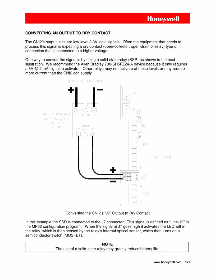
www.honeywell.com 171
CONVERTING AN OUTPUT TO DRY CONTACT
The CNI2’s output lines are low-level 3.3V logic signals. Often the equipment that needs to process this signal is expecting a dry-contact (open-collector, open-drain or relay) type of connection that is connected to a higher voltage. One way to convert the signal is by using a solid-state relay (SSR) as shown in the next illustration. We recommend the Allen Bradley 700-SH5FZ24-A device because it only requires a 3V @ 2 mA signal to activate. Other relays may not activate at these levels or may require more current than the CNI2 can supply.
Converting the CNI2’s “J7” Output to Dry Contact In this example the SSR is connected to the J7 connector. This signal is defined as “Line-12” in the MP32 configuration program. When the signal at J7 goes high it activates the LED within the relay, which is then sensed by the relay’s internal optical sensor, which then turns on a semiconductor switch (MOSFET).
NOTE The use of a solid-state relay may greatly reduce battery life.
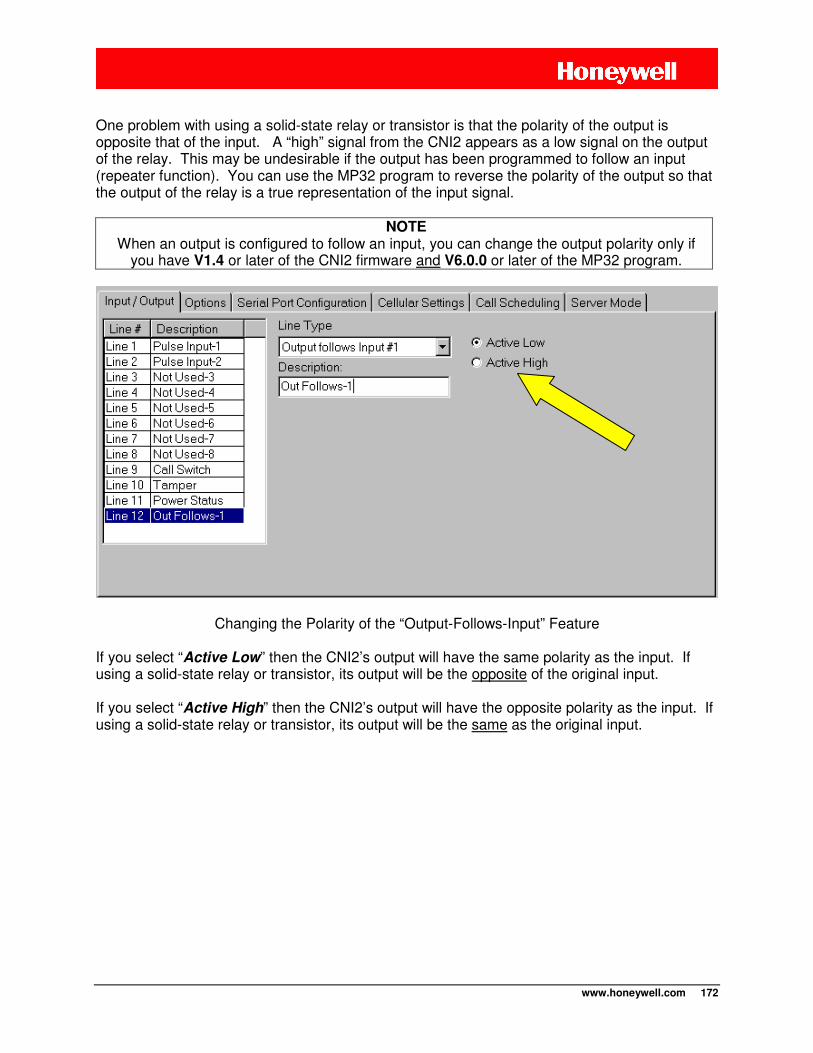
www.honeywell.com 172
One problem with using a solid-state relay or transistor is that the polarity of the output is opposite that of the input. A “high” signal from the CNI2 appears as a low signal on the output of the relay. This may be undesirable if the output has been programmed to follow an input (repeater function). You can use the MP32 program to reverse the polarity of the output so that the output of the relay is a true representation of the input signal.
NOTE When an output is configured to follow an input, you can change the output polarity only if
you have V1.4 or later of the CNI2 firmware and V6.0.0 or later of the MP32 program.
Changing the Polarity of the “Output-Follows-Input” Feature If you select “Active Low” then the CNI2’s output will have the same polarity as the input. If using a solid-state relay or transistor, its output will be the opposite of the original input. If you select “Active High” then the CNI2’s output will have the opposite polarity as the input. If using a solid-state relay or transistor, its output will be the same as the original input.
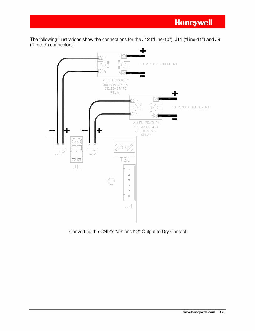
www.honeywell.com 173
The following illustrations show the connections for the J12 (“Line-10”), J11 (“Line-11”) and J9 (“Line-9”) connectors.
Converting the CNI2’s “J9” or “J12” Output to Dry Contact
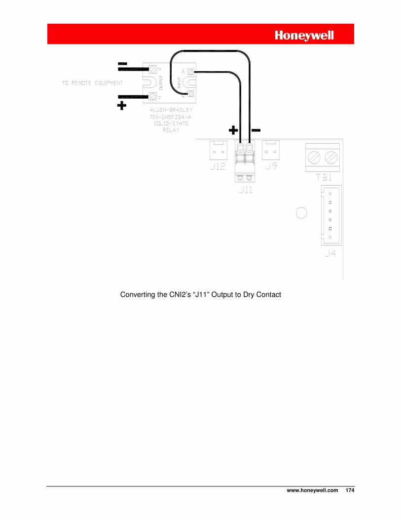
www.honeywell.com 174
Converting the CNI2’s “J11” Output to Dry Contact
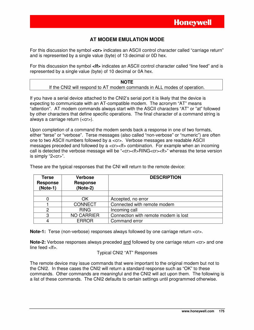
www.honeywell.com 175
AT MODEM EMULATION MODE
For this discussion the symbol <cr> indicates an ASCII control character called “carriage return” and is represented by a single value (byte) of 13 decimal or 0D hex. For this discussion the symbol <lf> indicates an ASCII control character called “line feed” and is represented by a single value (byte) of 10 decimal or 0A hex.
NOTE If the CNI2 will respond to AT modem commands in ALL modes of operation.
If you have a serial device attached to the CNI2’s serial port it is likely that the device is expecting to communicate with an AT-compatible modem. The acronym “AT” means “attention”. AT modem commands always start with the ASCII characters “AT” or ”at” followed by other characters that define specific operations. The final character of a command string is always a carriage return (<cr>). Upon completion of a command the modem sends back a response in one of two formats, either “terse” or “verbose”. Terse messages (also called “non-verbose” or “numeric”) are often one to two ASCII numbers followed by a <cr>. Verbose messages are readable ASCII messages preceded and followed by a <cr><lf> combination. For example when an incoming call is detected the verbose message will be “<cr><lf>RING<cr><lf>” whereas the terse version is simply “2<cr>”. These are the typical responses that the CNI will return to the remote device:
Terse Response (Note-1)
Verbose Response (Note-2)
DESCRIPTION
0 OK Accepted, no error 1 CONNECT Connected with remote modem 2 RING Incoming call 3 NO CARRIER Connection with remote modem is lost 4 ERROR Command error
Note-1: Terse (non-verbose) responses always followed by one carriage return <cr>. Note-2: Verbose responses always preceded and followed by one carriage return <cr> and one line feed <lf>.
Typical CNI2 “AT” Responses The remote device may issue commands that were important to the original modem but not to the CNI2. In these cases the CNI2 will return a standard response such as “OK” to these commands. Other commands are meaningful and the CNI2 will act upon them. The following is a list of these commands. The CNI2 defaults to certain settings until programmed otherwise.
www.honeywell.com 176
ATV (response type) Command ATV, ATV0: This instructs the CNI2 to return “terse” (non-verbose or numeric) result codes starting with this command. ATV1 (default): This instructs the CNI2 to return “verbose” result codes starting with this command. This is the default setting
NOTE: An ATV command will override the Use Non-verbose Result Codes setting that was
programmed by MP32. ATE (echo) Command An AT modem can be instructed to immediately return every character it receives. This is called “echoing”. The “ATE” command controls this function. The default is echo OFF.
ATE, ATE0 (default): This instructs the CNI2 to disable echoing starting with the next command. ATE1: This instructs the CNI2 to enable echoing starting with the next command. ATH (hangup) Command ATH, ATH0: Once a connection has been established this instructs the CNI2 to terminate the connection with the central computer. The normal response to this is “NO CARRIER”. If a connection does not exist then the normal response will be “OK”. ATZ (reset) Command ATZ, ATZ0: Once a connection has been established this command instructs the CNI2 to terminate the connection with the central computer. The normal response to this is “NO CARRIER”. If a connection does not exist then the normal response will be “OK”. ATA (answer) Command ATA: This instructs the CNI2 to answer an incoming call and establish a connection with the central computer. The normal response is a “CONNECT” message if a connection is established or “NO CARRIER” if one could not be established. The CONNECT message can be modified using MP32. ATD (dial) Command ATDxxxx, ATDPxxxx, ATDTxxxx: This instructs the CNI2 to establish a connection to the central computer. The “xxxx” portion of this command is the phone number or IP address of the central office. For “ATD” commands with no phone number included, the CNI2 will use the primary destination phone number or IP address that was programmed by MP32. The normal response is a “CONNECT” message if a connection is established or “NO CARRIER” if one could not be established. The CONNECT message can be modified using MP32. For CSD calls the “xxxx” portion of the ATD command is the destination phone number followed by a <cr>. Example ATD3215551212<cr> will dial the number 555-12212 in area code 321.
www.honeywell.com 177
For IP mode the “xxxx” portion of the ATD command is IP address/Port Number <cr>. For example ATD192.34.165.29/23267 will connect to IP address 192.34.165.29 on Port #23267.
NOTE If the CNI2 detects a decimal point (.) or a forward slash (/) in the dial string it will assume
this is an IP address and Port #, and not a standard phone number. +++ (escape) Command Once the CNI2 has established a connection with the central computer it can no longer respond to AT commands. However AT modems are always looking for an “escape” sequence, which is “+++” preceded and followed by 1 second of quiet time. This will return the CNI2 to command mode and the unit will respond with an “OK” message. Following this the CNI2 will wait 5 seconds to receive an “ATH” (hangup) command from the device. If the command is received, or 5 seconds elapse, the CNI2 will terminate the connection with the central computer and will return a “NO CARRIER” message to the remote device. AT Command Chaining “AT” commands can be grouped together into one string. For example, the command “ATE0V1” commands the CNI2 to turn off echoing and return verbose responses. However “ATA”, “ATH” or “ATD” commands should be sent separately or should be the last command in a chain. AT+ICLK? (time and date) Command This command will return time and date information to the serial device. The response will be formatted as follows, including delimiters such as quotation marks (“), forward slash (/) and colon (:):
<cr><lf>+ICLK: "yy/MM/dd,hh:mm:ss±zz"<cr><lf> where:
yy = 2-digit year [00-99], as in 2000-2099] MM = 2-digit month [01-12] dd = 2-digit day of month [00-31] hh = 2-digit hour [00-23] mm = 2-digit minute [00-59] ss = 2-digit seconds [00-59] ± = “+” or “-“ zz = time zone offset from GMT(UTC) in ¼ hour increments [-48 to +48]
If the CNI2 does not have a valid time an “ERROR” message will be returned instead. In order for the CNI2 to provide a valid response it must be given time and date information by some computer system. The CNI2 does not get its time from the cellular network.
www.honeywell.com 178
Here are some things to consider when using the AT+ICLK? command:
• If the CNI2 receives its time from a computer running MV90®, DC-2009®, InvisiConnect® or Masterlink® software the CNI2’s time represents the time on the computer system. If the CNI2 is in a different time zone then the “zz” offset will represent the time zone in which the computer is located.
• When configured as a Metretek SIP data logger the time given to the CNI2 does not contain any information about year, month or day. So these values in the response, as well as the time zone offset, will be incorrect.
• When configured as an SMS Modem the CNI2 will respond with an “ERROR” message.
• When configured as an InvisiConnect® device, in order for the CNi2 to receive time and
date information from the InvisiConnect® Server, the “Provide Time/Date Updates to Remote Devices” feature must be turned on in the InvisiConnect® software.
• When configured as a Transparent Modem, or if a schedule for Server sessions has
been defined, shortly after a power up or reset the CNI2 will attempt to call one of five time servers managed by the United States National Institute of Standards and Technology (NIST). If it is unable to obtain the time it will try again every 30 minutes. Once the time is obtained the CNI2 will attempt to contact a NIST time server every four days to update the clock. See the section of this manual titled “Server Mode” for details.
AT+TOTALS? Command This command allows the user to see the totalizer values from all pulse-counting channels. For example for a CNI2 that has been configured to count pulses on Lines 1, 5, 6 and 10 the response will be: <cr><lf>+TOTALS: <cr><lf> L01=00000000124<cr><lf> L05=0000009876<cr><lf> L06=0000000000<cr><lf> L10=0000000013<cr><lf> <cr><lf>OK<cr><lf> For a unit that has been configured to count pulses on Line 1 only the response will be: <cr><lf>+TOTALS: <cr><lf> L01=0000000124<cr><lf> <cr><lf>OK<cr><lf>

www.honeywell.com 179
AT+PORTx Command The AT+PORTx command selects the requested serial port (x = 1 - 8) if that port has been enabled. If so an "OK" is returned and then the requested port is selected and initialized. If the port number is out of the range of 1-8 then an "ERROR" message is transmitted. If the requested port has not been enabled then the following response is returned:
"INVALID PORT NUMBER OR PORT IS NOT ENABLED"
NOTE Once the new port is selected you will likely not be able to communicate with the CNI2 again until you physically connect to the new port and match that port’s baud rate, number of stop
bits etc.
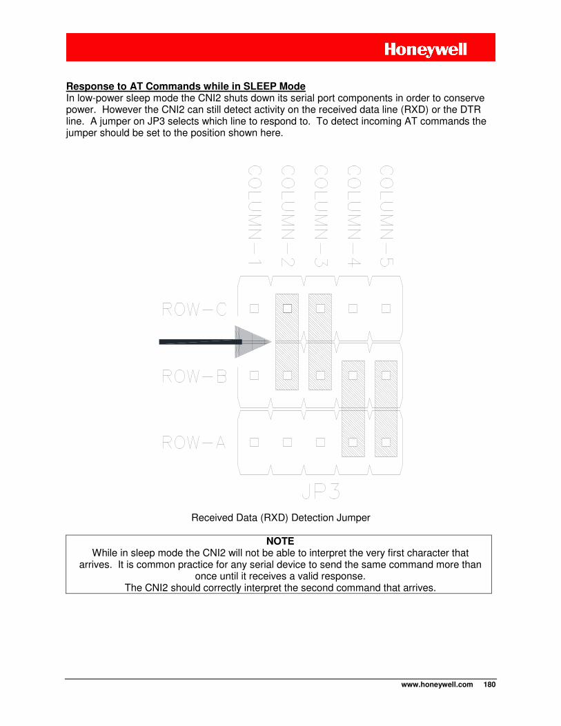
www.honeywell.com 180
Response to AT Commands while in SLEEP Mode In low-power sleep mode the CNI2 shuts down its serial port components in order to conserve power. However the CNI2 can still detect activity on the received data line (RXD) or the DTR line. A jumper on JP3 selects which line to respond to. To detect incoming AT commands the jumper should be set to the position shown here.
Received Data (RXD) Detection Jumper
NOTE While in sleep mode the CNI2 will not be able to interpret the very first character that
arrives. It is common practice for any serial device to send the same command more than once until it receives a valid response.
The CNI2 should correctly interpret the second command that arrives.
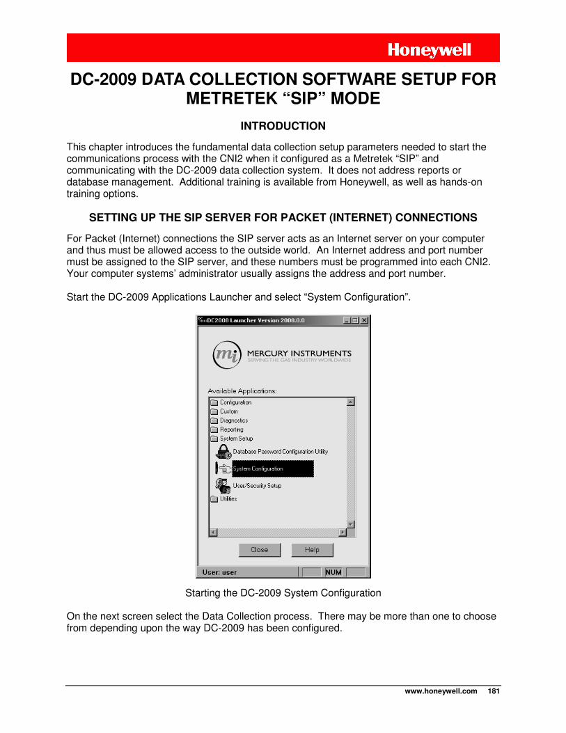
www.honeywell.com 181
INTRODUCTION
This chapter introduces the fundamental data collection setup parameters needed to start the communications process with the CNI2 when it configured as a Metretek “SIP” and communicating with the DC-2009 data collection system. It does not address reports or database management. Additional training is available from Honeywell, as well as hands-on training options.
SETTING UP THE SIP SERVER FOR PACKET (INTERNET) CONNECTIONS
For Packet (Internet) connections the SIP server acts as an Internet server on your computer and thus must be allowed access to the outside world. An Internet address and port number must be assigned to the SIP server, and these numbers must be programmed into each CNI2. Your computer systems’ administrator usually assigns the address and port number. Start the DC-2009 Applications Launcher and select “System Configuration”.
Starting the DC-2009 System Configuration
On the next screen select the Data Collection process. There may be more than one to choose from depending upon the way DC-2009 has been configured.
DC-2009 DATA COLLECTION SOFTWARE SETUP FOR METRETEK “SIP” MODE
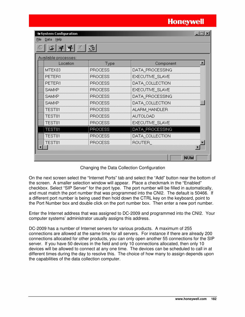
www.honeywell.com 182
Changing the Data Collection Configuration
On the next screen select the “Internet Ports” tab and select the “Add” button near the bottom of the screen. A smaller selection window will appear. Place a checkmark in the “Enabled” checkbox. Select “SIP Server” for the port type. The port number will be filled in automatically, and must match the port number that was programmed into the CNI2. The default is 50466. If a different port number is being used then hold down the CTRL key on the keyboard, point to the Port Number box and double click on the port number box. Then enter a new port number. Enter the Internet address that was assigned to DC-2009 and programmed into the CNI2. Your computer systems’ administrator usually assigns this address. DC-2009 has a number of Internet servers for various products. A maximum of 255 connections are allowed at the same time for all servers. For instance if there are already 200 connections allocated for other products, you can only open another 55 connections for the SIP server. If you have 50 devices in the field and only 10 connections allocated, then only 10 devices will be allowed to connect at any one time. The devices can be scheduled to call in at different times during the day to resolve this. The choice of how many to assign depends upon the capabilities of the data collection computer.
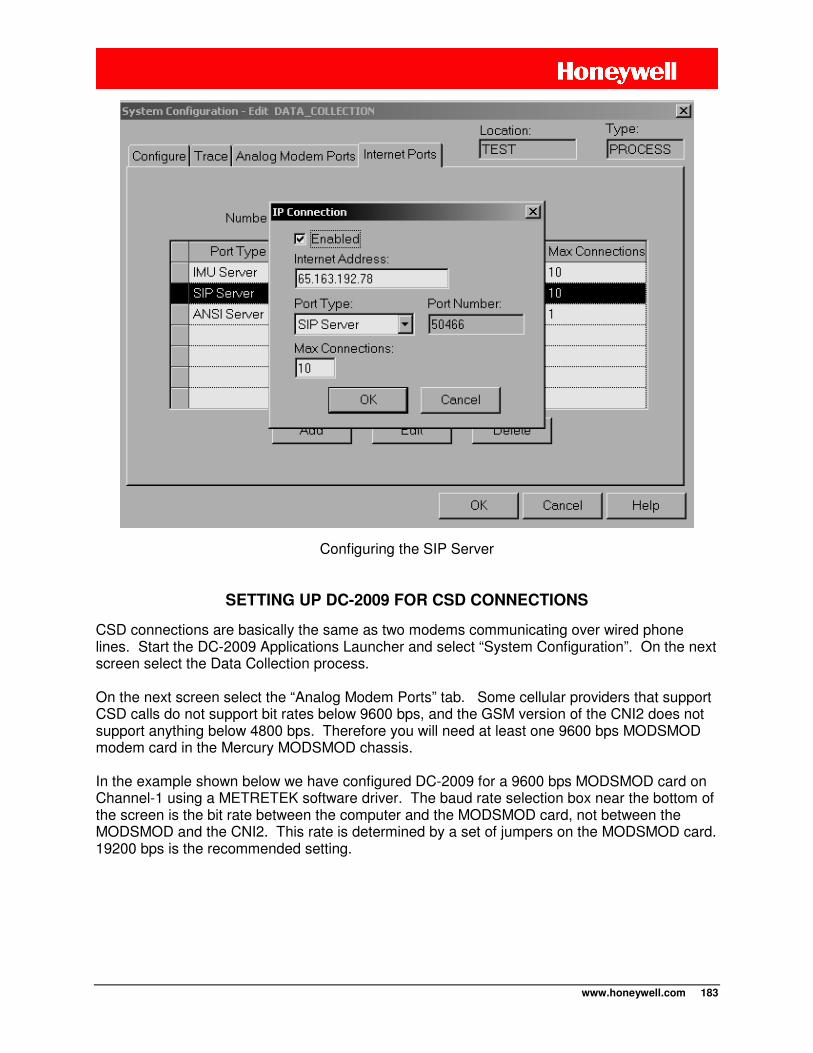
www.honeywell.com 183
Configuring the SIP Server
SETTING UP DC-2009 FOR CSD CONNECTIONS
CSD connections are basically the same as two modems communicating over wired phone lines. Start the DC-2009 Applications Launcher and select “System Configuration”. On the next screen select the Data Collection process. On the next screen select the “Analog Modem Ports” tab. Some cellular providers that support CSD calls do not support bit rates below 9600 bps, and the GSM version of the CNI2 does not support anything below 4800 bps. Therefore you will need at least one 9600 bps MODSMOD modem card in the Mercury MODSMOD chassis. In the example shown below we have configured DC-2009 for a 9600 bps MODSMOD card on Channel-1 using a METRETEK software driver. The baud rate selection box near the bottom of the screen is the bit rate between the computer and the MODSMOD card, not between the MODSMOD and the CNI2. This rate is determined by a set of jumpers on the MODSMOD card. 19200 bps is the recommended setting.
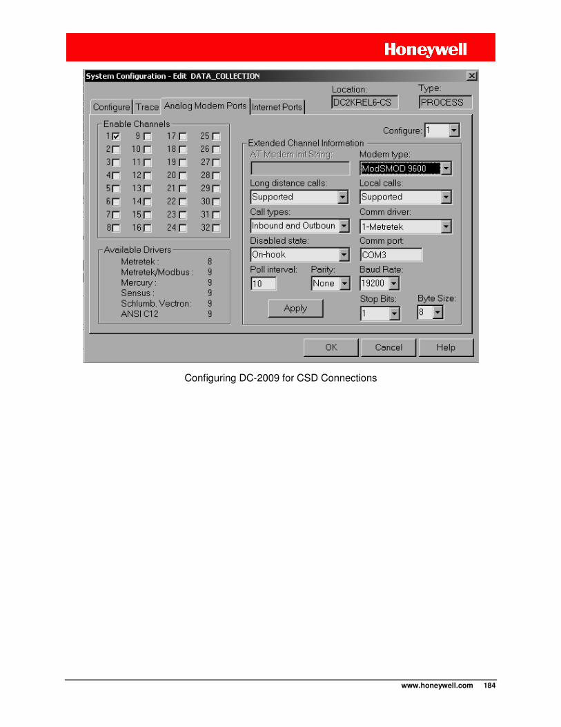
www.honeywell.com 184
Configuring DC-2009 for CSD Connections
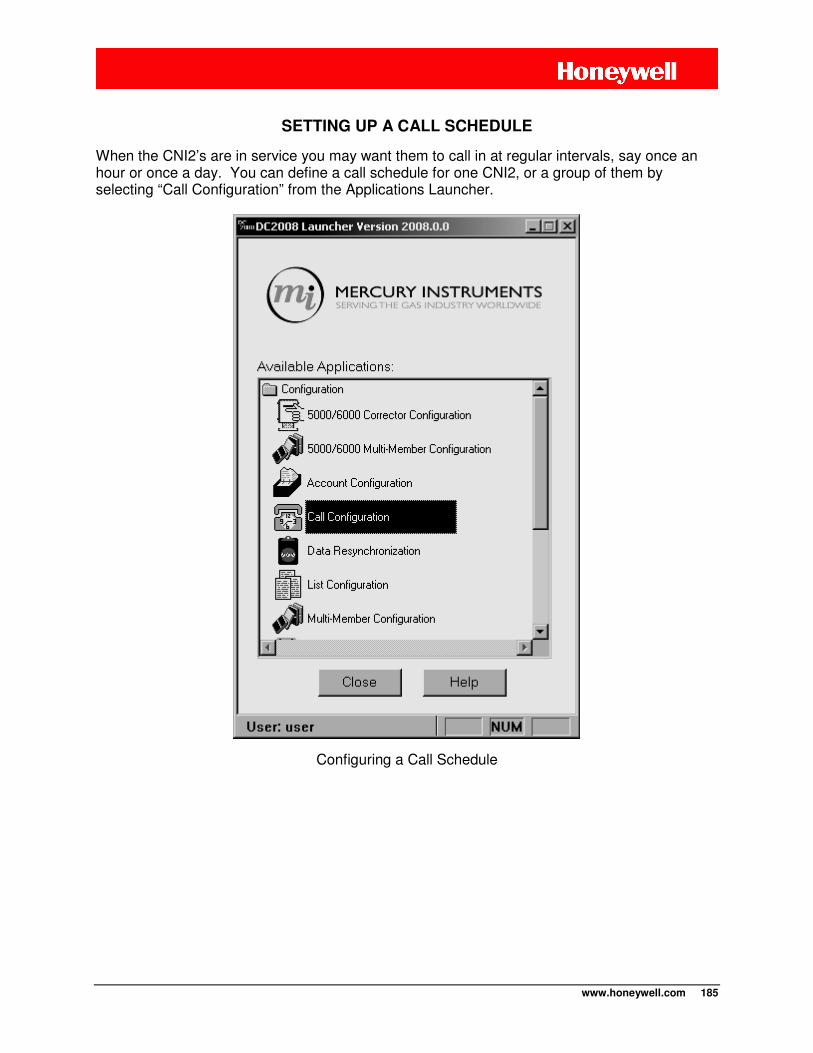
www.honeywell.com 185
SETTING UP A CALL SCHEDULE
When the CNI2’s are in service you may want them to call in at regular intervals, say once an hour or once a day. You can define a call schedule for one CNI2, or a group of them by selecting “Call Configuration” from the Applications Launcher.
Configuring a Call Schedule
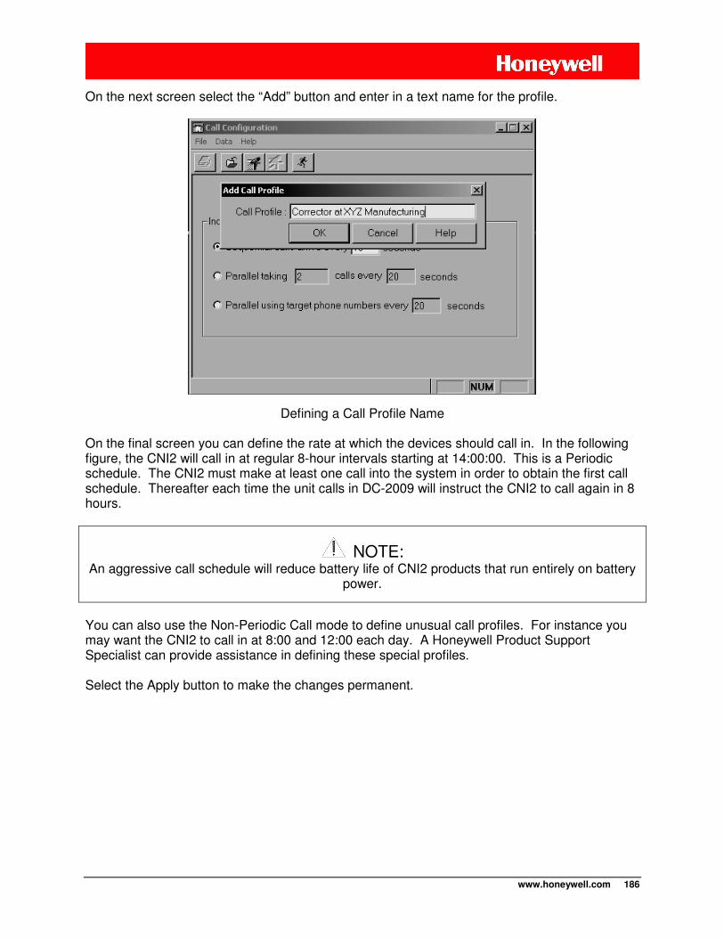
www.honeywell.com 186
On the next screen select the “Add” button and enter in a text name for the profile.
Defining a Call Profile Name
On the final screen you can define the rate at which the devices should call in. In the following figure, the CNI2 will call in at regular 8-hour intervals starting at 14:00:00. This is a Periodic schedule. The CNI2 must make at least one call into the system in order to obtain the first call schedule. Thereafter each time the unit calls in DC-2009 will instruct the CNI2 to call again in 8 hours.
NOTE: An aggressive call schedule will reduce battery life of CNI2 products that run entirely on battery
power.
You can also use the Non-Periodic Call mode to define unusual call profiles. For instance you may want the CNI2 to call in at 8:00 and 12:00 each day. A Honeywell Product Support Specialist can provide assistance in defining these special profiles. Select the Apply button to make the changes permanent.
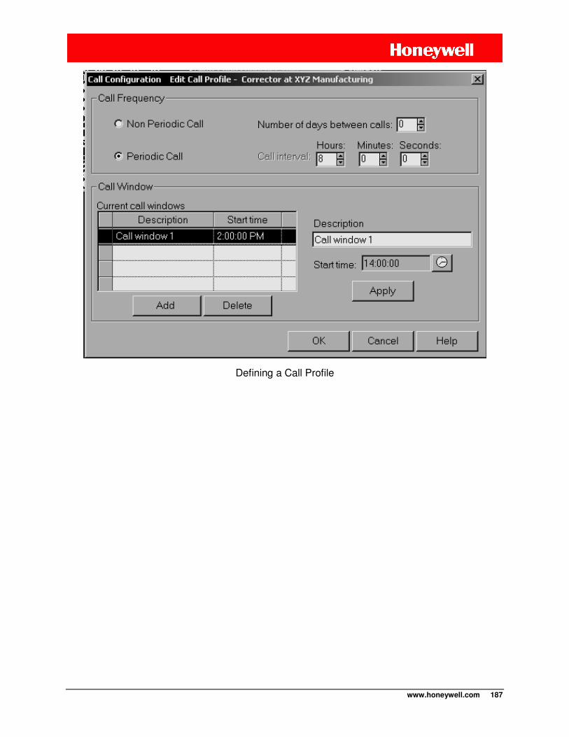
www.honeywell.com 187
Defining a Call Profile
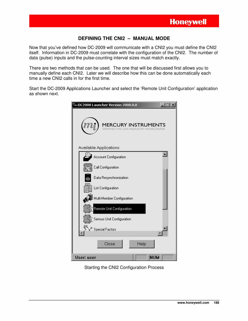
www.honeywell.com 188
DEFINING THE CNI2 – MANUAL MODE
Now that you’ve defined how DC-2009 will communicate with a CNI2 you must define the CNI2 itself. Information in DC-2009 must correlate with the configuration of the CNI2. The number of data (pulse) inputs and the pulse-counting interval sizes must match exactly. There are two methods that can be used. The one that will be discussed first allows you to manually define each CNI2. Later we will describe how this can be done automatically each time a new CNI2 calls in for the first time. Start the DC-2009 Applications Launcher and select the ‘Remote Unit Configuration’ application as shown next.
Starting the CNI2 Configuration Process
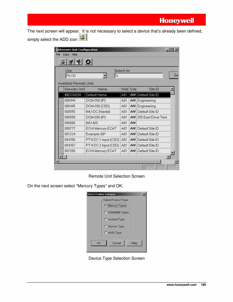
www.honeywell.com 189
The next screen will appear. It is not necessary to select a device that’s already been defined,
simply select the ADD icon
Remote Unit Selection Screen
On the next screen select “Mercury Types” and OK.
Device Type Selection Screen
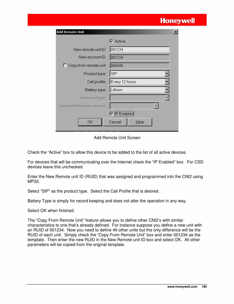
www.honeywell.com 190
Add Remote Unit Screen
Check the “Active” box to allow this device to be added to the list of all active devices. For devices that will be communicating over the Internet check the “IP Enabled” box. For CSD devices leave this unchecked. Enter the New Remote unit ID (RUID) that was assigned and programmed into the CNI2 using MP32. Select “SIP” as the product type. Select the Call Profile that is desired. Battery Type is simply for record keeping and does not alter the operation in any way. Select OK when finished. The “Copy From Remote Unit” feature allows you to define other CNI2’s with similar characteristics to one that’s already defined. For instance suppose you define a new unit with an RUID of 001234. Now you need to define 49 other units but the only difference will be the RUID of each unit. Simply check the “Copy From Remote Unit” box and enter 001234 as the template. Then enter the new RUID in the New Remote unit ID box and select OK. All other parameters will be copied from the original template.
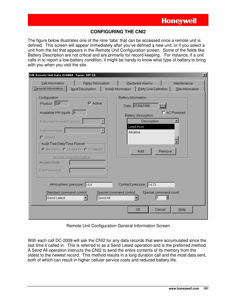
www.honeywell.com 191
CONFIGURING THE CNI2
The figure below illustrates one of the nine ‘tabs’ that can be accessed once a remote unit is defined. This screen will appear immediately after you’ve defined a new unit, or if you select a unit from the list that appears in the Remote Unit Configuration screen. Some of the fields like Battery Description are not critical and are primarily for record keeping. For instance, if a unit calls in to report a low-battery condition, it might be handy to know what type of battery to bring with you when you visit the site.
Remote Unit Configuration General Information Screen
With each call DC-2009 will ask the CNI2 for any data records that were accumulated since the last time it called in. This is referred to as a Send Latest operation and is the preferred method. A Send All operation instructs the CNI2 to send the entire contents of its memory from the oldest to the newest record. This method results in a long duration call and the most data sent, both of which can result in higher cellular service costs and reduced battery life.
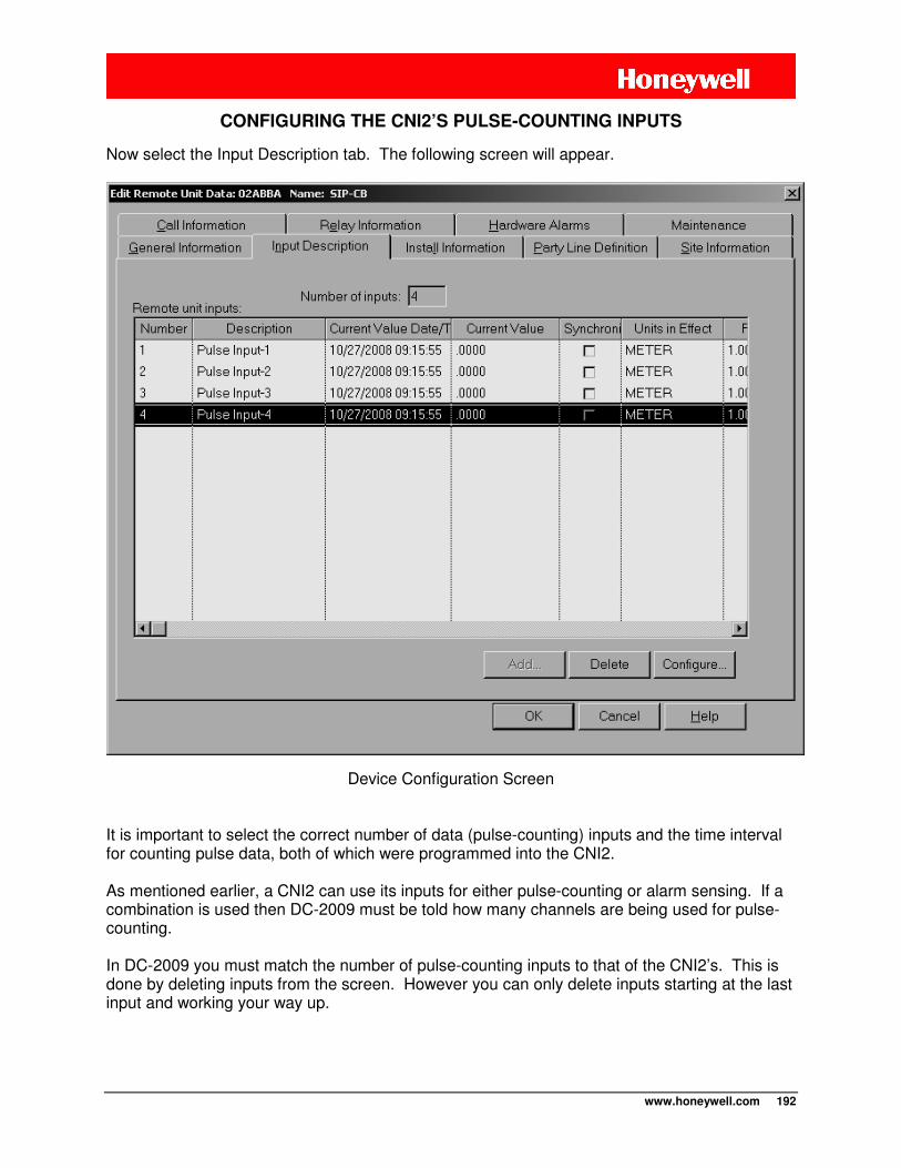
www.honeywell.com 192
CONFIGURING THE CNI2’S PULSE-COUNTING INPUTS
Now select the Input Description tab. The following screen will appear.
Device Configuration Screen
It is important to select the correct number of data (pulse-counting) inputs and the time interval for counting pulse data, both of which were programmed into the CNI2. As mentioned earlier, a CNI2 can use its inputs for either pulse-counting or alarm sensing. If a combination is used then DC-2009 must be told how many channels are being used for pulse-counting. In DC-2009 you must match the number of pulse-counting inputs to that of the CNI2’s. This is done by deleting inputs from the screen. However you can only delete inputs starting at the last input and working your way up.
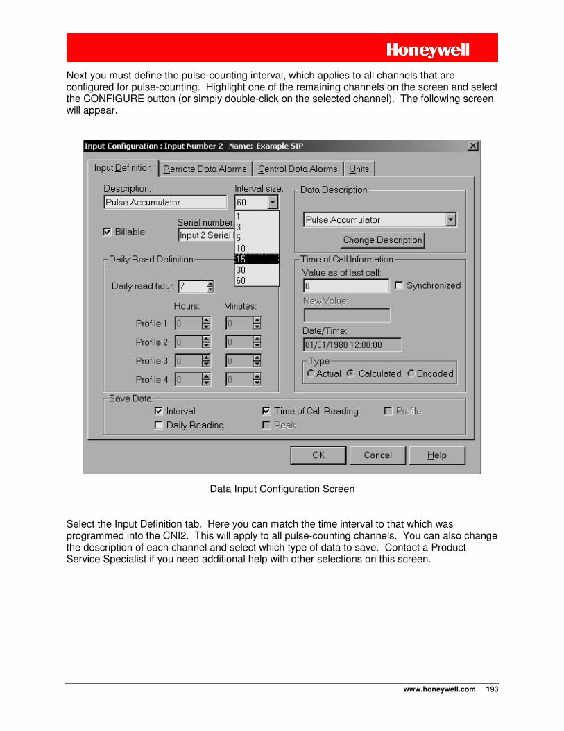
www.honeywell.com 193
Next you must define the pulse-counting interval, which applies to all channels that are configured for pulse-counting. Highlight one of the remaining channels on the screen and select the CONFIGURE button (or simply double-click on the selected channel). The following screen will appear.
Data Input Configuration Screen
Select the Input Definition tab. Here you can match the time interval to that which was programmed into the CNI2. This will apply to all pulse-counting channels. You can also change the description of each channel and select which type of data to save. Contact a Product Service Specialist if you need additional help with other selections on this screen.
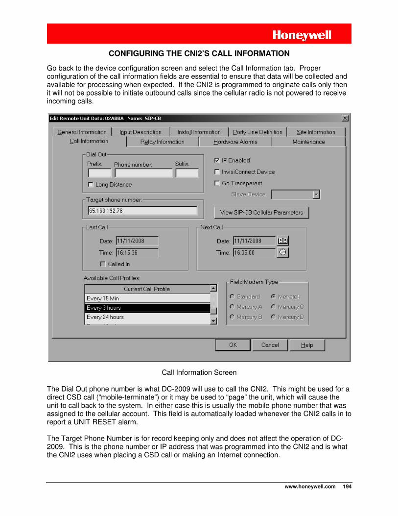
www.honeywell.com 194
CONFIGURING THE CNI2’S CALL INFORMATION
Go back to the device configuration screen and select the Call Information tab. Proper configuration of the call information fields are essential to ensure that data will be collected and available for processing when expected. If the CNI2 is programmed to originate calls only then it will not be possible to initiate outbound calls since the cellular radio is not powered to receive incoming calls.
Call Information Screen
The Dial Out phone number is what DC-2009 will use to call the CNI2. This might be used for a direct CSD call (“mobile-terminate”) or it may be used to “page” the unit, which will cause the unit to call back to the system. In either case this is usually the mobile phone number that was assigned to the cellular account. This field is automatically loaded whenever the CNI2 calls in to report a UNIT RESET alarm. The Target Phone Number is for record keeping only and does not affect the operation of DC-2009. This is the phone number or IP address that was programmed into the CNI2 and is what the CNI2 uses when placing a CSD call or making an Internet connection.
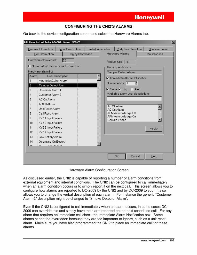
www.honeywell.com 195
CONFIGURING THE CNI2’S ALARMS
Go back to the device configuration screen and select the Hardware Alarms tab.
Hardware Alarm Configuration Screen As discussed earlier, the CNI2 is capable of reporting a number of alarm conditions from external equipment and internal conditions. The CNI2 can be configured to call immediately when an alarm condition occurs or to simply report it on the next call. This screen allows you to configure how alarms are reported to DC-2009 by the CNI2 and by DC-2009 to you. It also allows you to change the verbal description of each alarm. For instance the generic “Customer Alarm-2” description might be changed to “Smoke Detector Alarm”. Even if the CNI2 is configured to call immediately when an alarm occurs, in some cases DC-2009 can override this and simply have the alarm reported on the next scheduled call. For any alarm that requires an immediate call check the Immediate Alarm Notification box. Some alarms cannot be overridden because they are too important to ignore, such as a unit reset alarm. Make sure you have also programmed the CNI2 to place an immediate call for these alarms.
www.honeywell.com 196
The Nuisance Limit can be used to disable calls due to a repeating alarm condition. As an example, say the CNI2 is scheduled to call in every 12 hours. One of the alarm inputs comes from a pressure sensor which has become defective. Until the sensor is repaired the CNI2 will keep calling in every couple of minutes to report a the pressure alarm. This is especially undesirable for battery-operated units because each call consumes power. But if you set the Nuisance Limit to 3 then DC-2009 will instruct the CNI2 to stop calling in after the third report of the same alarm. Later, when the CNI2 calls in at its regularly-scheduled time (12 hours later), the Nuisance Limit will be reset and the unit will again be allowed to report the alarm up to 3 times until the next scheduled call. The SAVE checkbox allows the alarm condition to be recorded in the database. The LOG checkbox allows the alarm to be reported to the computer’s printer or screen. The ALERT checkbox will activate the printer’s audio alarm if a printer is used. For each alarm be sure to select the APPLY button after you make any changes. Note: Changes made to any alarm configuration will not go into effect until the next communication with the CNI2. Here is a general list of the alarms supported by the CNI2. You can change the description of each alarm to more accurately describe its purpose. For instance “Customer Alarm 1” could be changed to “High Pressure”. Most electrical switches have only two contacts and are either normally-open (Form-A) or normally-closed (Form-B). A third configuration, Form-C, contains two switches, one of each type. Customer Alarm-1 If Line #1 has been configured as a Form-A or Form-B alarm input the alarm will be reported as a “Customer Alarm-1” alarm. If the combination of Line #1 & #2 has been configured as a Form-C alarm, then the alarm condition itself will be reported as a “Customer Alarm-1” alarm. If a switch failure is detected, the failure is reported as a “Customer Alarm-2” alarm. Customer Alarm-2 If Line #2 has been configured as a Form-A or Form-B alarm input the alarm will be reported as a “Customer Alarm-2” alarm. If the combination of Line #1 & #2 has been configured as a Form-C alarm then see the discussion for the Customer Alarm-1 alarm. Magnetic or ”CALL” Switch Alarm If Line #9 has been configured as a Form-A or Form-B alarm input the alarm will be reported as a MAGNETIC SWITCH or CALL SWITCH alarm. If the combination of Line #9 & #10 has been configured as a Form-C alarm, then the alarm condition itself will be reported as a MAGNETIC SWITCH or CALL SWITCH alarm. If a switch failure is detected, the failure is reported as a TAMPER alarm.
www.honeywell.com 197
TAMPER Detect Alarm If Line #10 has been configured as a Form-A or Form-B alarm input the alarm will be reported as a TAMPER alarm. If the combination of Line #9 & #10 has been configured as a Form-C alarm then see the discussion for the Magnetic or “CALL” Switch alarm. AC-OFF Alarm If Line #11 has been configured as a Form-A or Form-B alarm input an active alarm will be reported as an AC-OFF alarm. AC-ON Alarm If Line #11 has been configured as a Form-A or Form-B alarm input an inactive alarm will be reported as an AC-ON alarm. Unit Reset Alarm Reports if the CNI2 has been reset. A reset can be caused by the following conditions:
1 - The JP4 reset pins are shorted together.
2 - The board’s configuration memory or operating code has been changed or read using the programming cable.
3 - The battery is nearly exhausted and can no longer support the current required by the board.
Call Retry Alarm If a previous call attempt failed then this alarm will be reported on the next successful call. Numerous Call Retry alarms may be an indication of network problems or that the unit is located in a marginal reception area. It may also happen if too many units are programmed to call the data collection system at the same time. Queue Full Alarm If pulse data is not collected often enough there is a chance that the oldest data may be lost due to insufficient memory. This memory is referred to as the “queue” and the CNI2 will call in to report a “Queue Full” alarm when a certain percentage of the queue contains new records. Default value is 75% but can be changed using MP32. Clock Resync Alarm The CNI2’s time-of-day clock is updated each time it calls in to the data collection system. A Clock Resync alarm is reported if the CNI2’s clock has been corrected by more than ±20 seconds, and will be reported on the next call. Be aware that there will always be a Clock Resync alarm reported on the next call after a unit reset call, and this is normal. Frequent Clock Resync alarms may indicate one of the following problems:
1 - The CNI2 cannot properly keep time due to a timekeeping hardware fault.
www.honeywell.com 198
2 - The time given to the CNI2 is taken from the computer’s time-of-day clock. This alarm may indicate that the computer’s clock is inaccurate (slow, fast or has been changed since the last call, such as a daylight savings time (DST) change).
3 - If the CNI2 is programmed to call more than one computer, and the computers’ clocks are different by more than 20 seconds, this will result in Clock Resync alarms.
4 - During packet (Internet) connections DC-2009 prepares the message containing the new time-of-day and sends it to the CNI2. If a packet does not arrive after a certain amount of time, the same packet is retransmitted. This will be repeated several more times before the connection is terminated. If it takes over 20 seconds to deliver the packet, then the time in the message will be 20 seconds older than the CNI2’s current time.
Remote Daily Volume Low Input-1,2,3,4 These alarms occur if the daily volume use is below the limits for pulse inputs 1, 2, 3 and 4, respectively. Remote Daily Volume High Input-1,2,3,4 These alarms occur if the daily volume use is above the limits for pulse inputs 1, 2, 3 and 4, respectively. Remote TTI Consumption Low Input-1,2,3,4 These alarms occur if the interval volume use is below the limits for pulse inputs 1, 2, 3 and 4, respectively. Remote TTI Consumption High Input-1,2,3,4 These alarms occur if the interval volume use is above the limits for pulse inputs 1, 2, 3 and 4, respectively.
Low Battery Alarm This alarm indicates that the battery pack in the CNI2 needs to be replaced as soon as possible. The voltage level at which the alarm will occur is programmed using MP32. The battery should be changed as soon as possible to continue uninterrupted service. Note About Batteries
Battery voltage level drops in cold weather. If the unit is located in cold climates you may receive occasional low-battery alarms as the temperature drops. As the unit warms up during the day the voltage may return to acceptable levels. However, any low-battery alarm should be taken seriously and the battery should be replaced soon. If the battery gets too low the unit may no longer be able to make calls and may not be able to save its’ pulse data.
www.honeywell.com 199
DEFINING THE CNI2 – AUTOMATIC MODE
Manually defining a large deployment of CNI2’s in larger systems can be tedious. In many cases the only difference between all of these units will be their remote unit ID (RUID) numbers. As long as all other parameters are the same there is a way to automate this process. First, go to the Remote Unit Selection Screen and locate a template called “$CNI2”. Select this for editing to define all of the parameters that you will need for your CNI2’s. If you look at the General Information tab on the Remote Unit Configuration screen you will see a checkbox called “Active”. As long as this box is checked any new CNI2 that calls in for the very first time will be automatically added to the system under the RUID number that was programmed into the unit. If the “Active” box is not checked then the call will be rejected unless you manually add the unit to the system.
STARTING DC-2009
Once all CNI2’s have been defined you can start DC-2009. For CSD connections the appropriate modem channels will be initialized. For packet (Internet) connections the SIP server will be started and will begin listening on the number of channels that were selected. DC-2009 is a powerful and highly-configurable application program. There are many features not discussed here. A Honeywell Product Support Specialist can provide more information and training options.
OBTAINING THE CNI2’S CELLULAR PHONE NUMBER
Whenever a CNI2 calls in to report a UNIT RESET alarm DC-2009 will ask for its Mobile Directory Number (MDN), which is usually the phone number that was assigned to the cellular account. DC-2009 saves this number in the database and also places it in the Call Information tab on the Remote Unit Configuration screen. It appears as the Dial-Out number. For this feature to work the mobile phone number must be stored on the SIM card. There are usually three or four memory slots reserved for this, one for voice (which is usually considered the primary mobile number), another for a data number (usually used for “mobile-terminate” CSD service) and a third for a FAX number. The CNI2 will report the 1st mobile number stored on the SIM card. If you are using the phone number for paging purposes then this should be the voice number. If you wish to make mobile-terminate CSD calls then this should be the data number. Confirm with your cellular service provider to make sure the right number is stored on the SIM card.
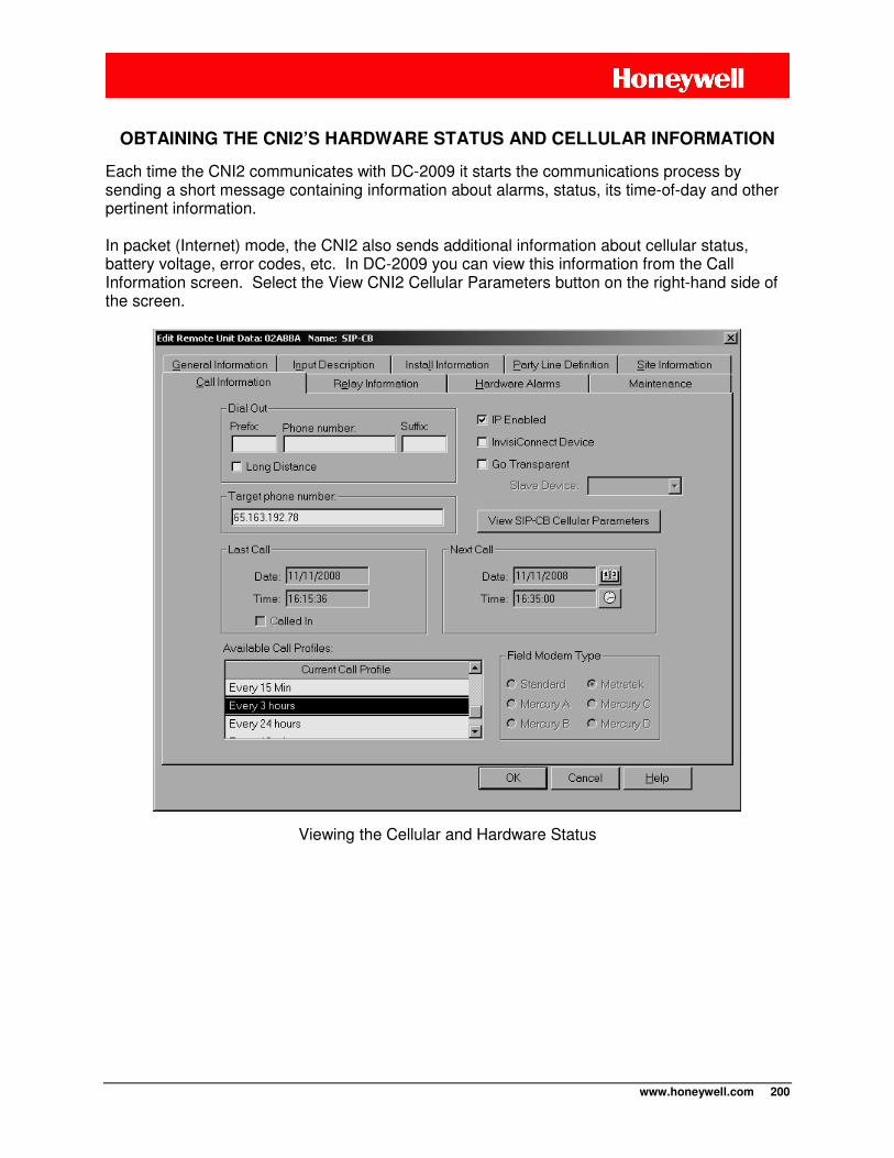
www.honeywell.com 200
OBTAINING THE CNI2’S HARDWARE STATUS AND CELLULAR INFORMATION
Each time the CNI2 communicates with DC-2009 it starts the communications process by sending a short message containing information about alarms, status, its time-of-day and other pertinent information. In packet (Internet) mode, the CNI2 also sends additional information about cellular status, battery voltage, error codes, etc. In DC-2009 you can view this information from the Call Information screen. Select the View CNI2 Cellular Parameters button on the right-hand side of the screen.
Viewing the Cellular and Hardware Status
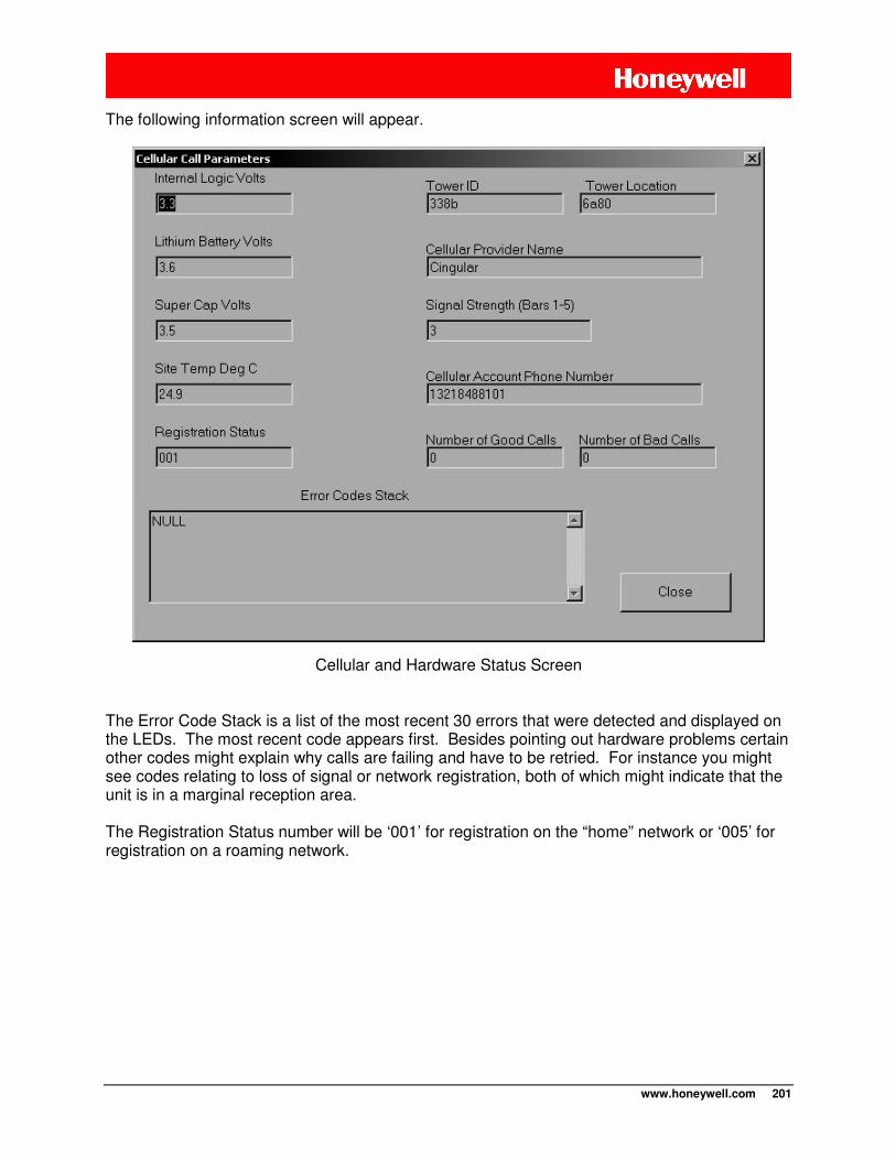
www.honeywell.com 201
The following information screen will appear.
Cellular and Hardware Status Screen
The Error Code Stack is a list of the most recent 30 errors that were detected and displayed on the LEDs. The most recent code appears first. Besides pointing out hardware problems certain other codes might explain why calls are failing and have to be retried. For instance you might see codes relating to loss of signal or network registration, both of which might indicate that the unit is in a marginal reception area. The Registration Status number will be ‘001’ for registration on the “home” network or ‘005’ for registration on a roaming network.
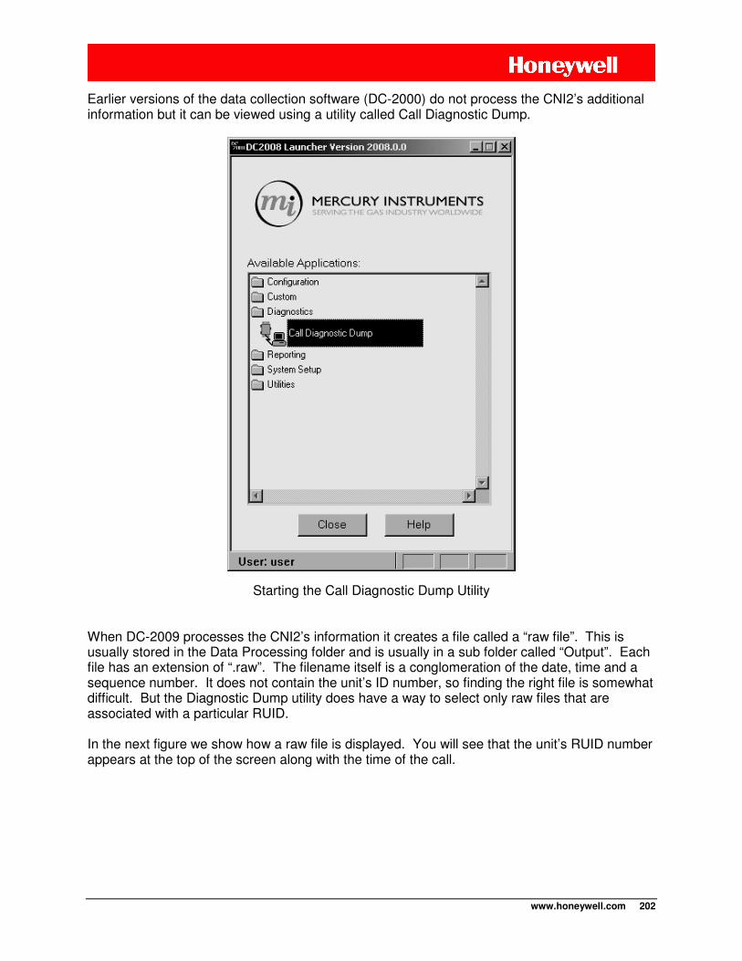
www.honeywell.com 202
Earlier versions of the data collection software (DC-2000) do not process the CNI2’s additional information but it can be viewed using a utility called Call Diagnostic Dump.
Starting the Call Diagnostic Dump Utility
When DC-2009 processes the CNI2’s information it creates a file called a “raw file”. This is usually stored in the Data Processing folder and is usually in a sub folder called “Output”. Each file has an extension of “.raw”. The filename itself is a conglomeration of the date, time and a sequence number. It does not contain the unit’s ID number, so finding the right file is somewhat difficult. But the Diagnostic Dump utility does have a way to select only raw files that are associated with a particular RUID. In the next figure we show how a raw file is displayed. You will see that the unit’s RUID number appears at the top of the screen along with the time of the call.
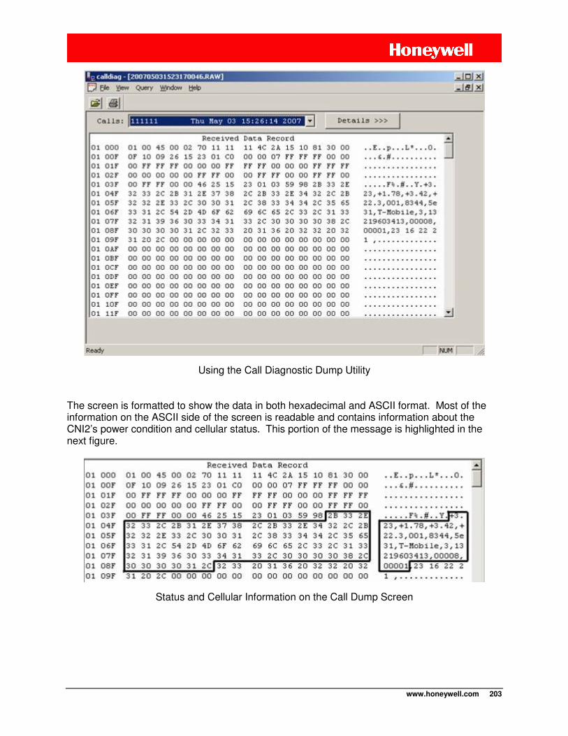
www.honeywell.com 203
Using the Call Diagnostic Dump Utility
The screen is formatted to show the data in both hexadecimal and ASCII format. Most of the information on the ASCII side of the screen is readable and contains information about the CNI2’s power condition and cellular status. This portion of the message is highlighted in the next figure.
Status and Cellular Information on the Call Dump Screen
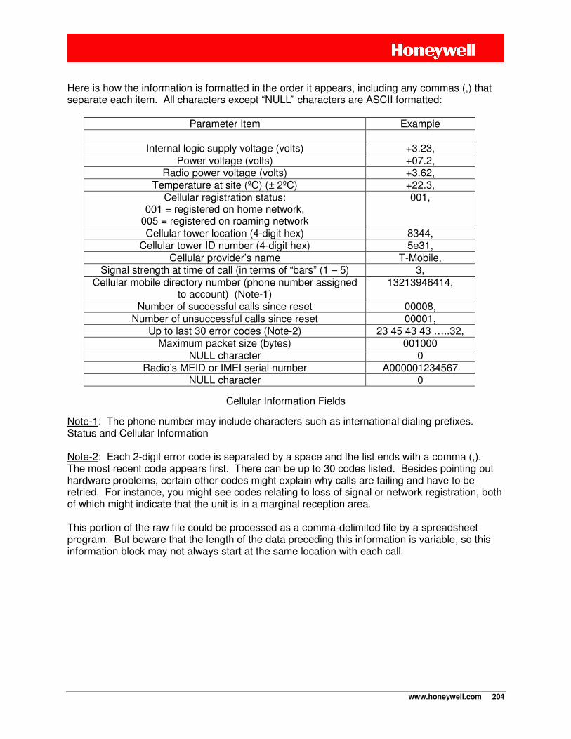
www.honeywell.com 204
Here is how the information is formatted in the order it appears, including any commas (,) that separate each item. All characters except “NULL” characters are ASCII formatted:
Parameter Item Example
Internal logic supply voltage (volts) +3.23,
Power voltage (volts) +07.2, Radio power voltage (volts) +3.62,
Temperature at site (ºC) (± 2ºC) +22.3, Cellular registration status:
001 = registered on home network, 005 = registered on roaming network
001,
Cellular tower location (4-digit hex) 8344, Cellular tower ID number (4-digit hex) 5e31,
Cellular provider’s name T-Mobile, Signal strength at time of call (in terms of “bars” (1 – 5) 3,
Cellular mobile directory number (phone number assigned to account) (Note-1)
13213946414,
Number of successful calls since reset 00008, Number of unsuccessful calls since reset 00001,
Up to last 30 error codes (Note-2) 23 45 43 43 …..32, Maximum packet size (bytes) 001000
NULL character 0 Radio’s MEID or IMEI serial number A000001234567
NULL character 0
Cellular Information Fields
Note-1: The phone number may include characters such as international dialing prefixes. Status and Cellular Information
Note-2: Each 2-digit error code is separated by a space and the list ends with a comma (,). The most recent code appears first. There can be up to 30 codes listed. Besides pointing out hardware problems, certain other codes might explain why calls are failing and have to be retried. For instance, you might see codes relating to loss of signal or network registration, both of which might indicate that the unit is in a marginal reception area.
This portion of the raw file could be processed as a comma-delimited file by a spreadsheet program. But beware that the length of the data preceding this information is variable, so this information block may not always start at the same location with each call.
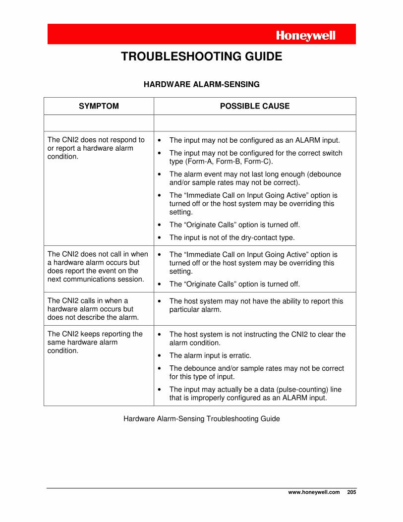
www.honeywell.com 205
HARDWARE ALARM-SENSING
SYMPTOM POSSIBLE CAUSE
The CNI2 does not respond to or report a hardware alarm condition.
• The input may not be configured as an ALARM input.
• The input may not be configured for the correct switch type (Form-A, Form-B, Form-C).
• The alarm event may not last long enough (debounce and/or sample rates may not be correct).
• The “Immediate Call on Input Going Active” option is turned off or the host system may be overriding this setting.
• The “Originate Calls” option is turned off.
• The input is not of the dry-contact type.
The CNI2 does not call in when a hardware alarm occurs but does report the event on the next communications session.
• The “Immediate Call on Input Going Active” option is turned off or the host system may be overriding this setting.
• The “Originate Calls” option is turned off.
The CNI2 calls in when a hardware alarm occurs but does not describe the alarm.
• The host system may not have the ability to report this particular alarm.
The CNI2 keeps reporting the same hardware alarm condition.
• The host system is not instructing the CNI2 to clear the alarm condition.
• The alarm input is erratic.
• The debounce and/or sample rates may not be correct for this type of input.
• The input may actually be a data (pulse-counting) line that is improperly configured as an ALARM input.
Hardware Alarm-Sensing Troubleshooting Guide
TROUBLESHOOTING GUIDE
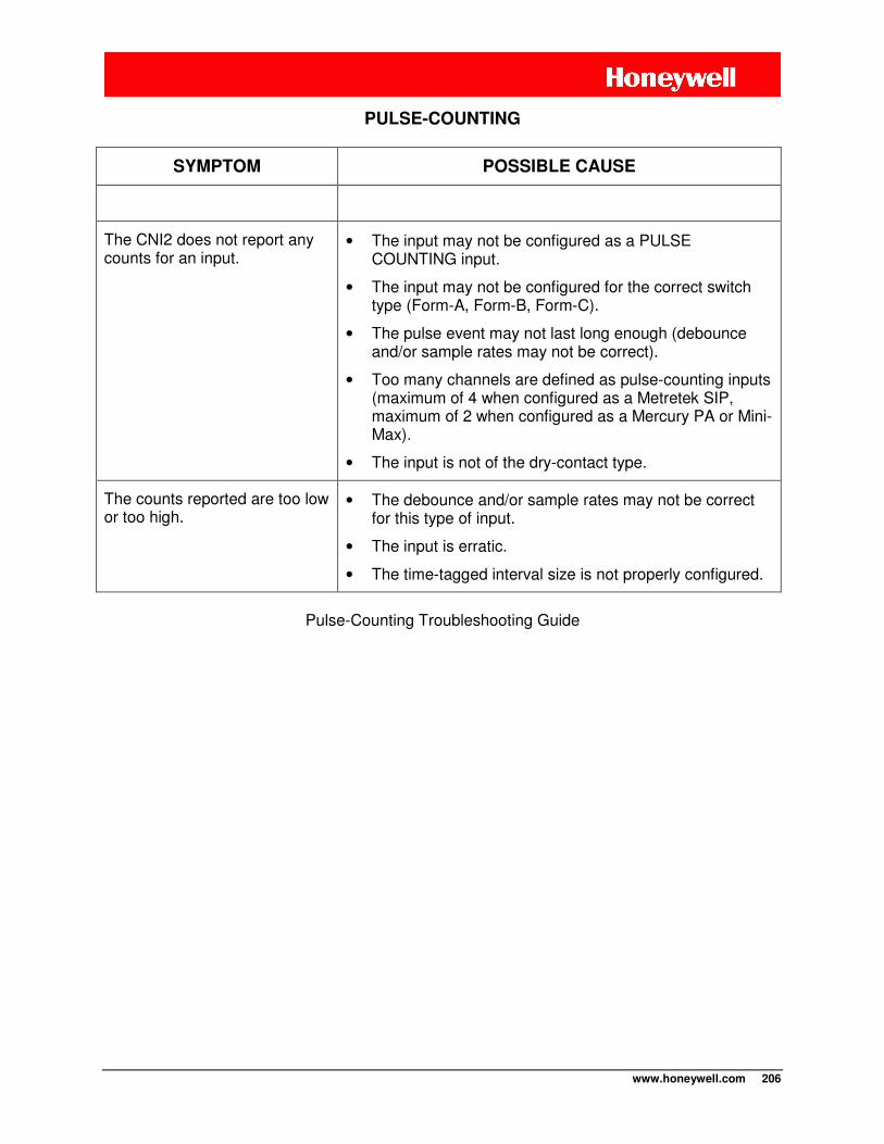
www.honeywell.com 206
PULSE-COUNTING
SYMPTOM POSSIBLE CAUSE
The CNI2 does not report any counts for an input.
• The input may not be configured as a PULSE COUNTING input.
• The input may not be configured for the correct switch type (Form-A, Form-B, Form-C).
• The pulse event may not last long enough (debounce and/or sample rates may not be correct).
• Too many channels are defined as pulse-counting inputs (maximum of 4 when configured as a Metretek SIP, maximum of 2 when configured as a Mercury PA or Mini-Max).
• The input is not of the dry-contact type.
The counts reported are too low or too high.
• The debounce and/or sample rates may not be correct for this type of input.
• The input is erratic.
• The time-tagged interval size is not properly configured.
Pulse-Counting Troubleshooting Guide
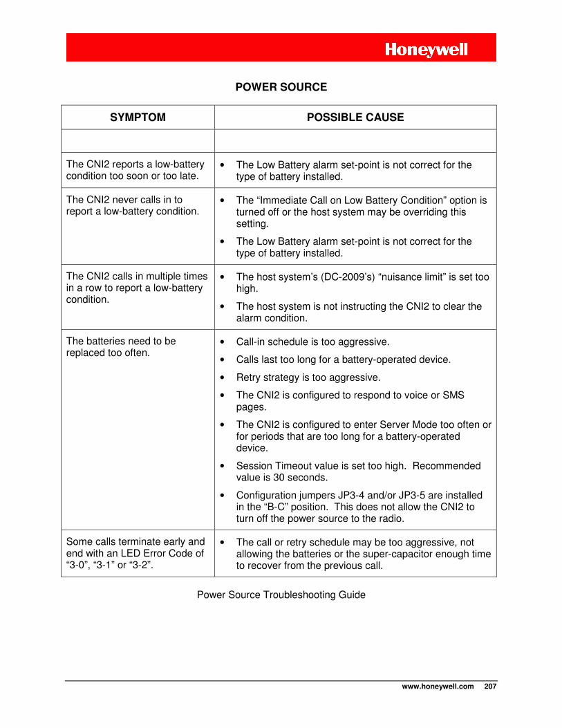
www.honeywell.com 207
POWER SOURCE
SYMPTOM POSSIBLE CAUSE
The CNI2 reports a low-battery condition too soon or too late.
• The Low Battery alarm set-point is not correct for the type of battery installed.
The CNI2 never calls in to report a low-battery condition.
• The “Immediate Call on Low Battery Condition” option is turned off or the host system may be overriding this setting.
• The Low Battery alarm set-point is not correct for the type of battery installed.
The CNI2 calls in multiple times in a row to report a low-battery condition.
• The host system’s (DC-2009’s) “nuisance limit” is set too high.
• The host system is not instructing the CNI2 to clear the alarm condition.
The batteries need to be replaced too often.
• Call-in schedule is too aggressive.
• Calls last too long for a battery-operated device.
• Retry strategy is too aggressive.
• The CNI2 is configured to respond to voice or SMS pages.
• The CNI2 is configured to enter Server Mode too often or for periods that are too long for a battery-operated device.
• Session Timeout value is set too high. Recommended value is 30 seconds.
• Configuration jumpers JP3-4 and/or JP3-5 are installed in the “B-C” position. This does not allow the CNI2 to turn off the power source to the radio.
Some calls terminate early and end with an LED Error Code of “3-0”, “3-1” or “3-2”.
• The call or retry schedule may be too aggressive, not allowing the batteries or the super-capacitor enough time to recover from the previous call.
Power Source Troubleshooting Guide
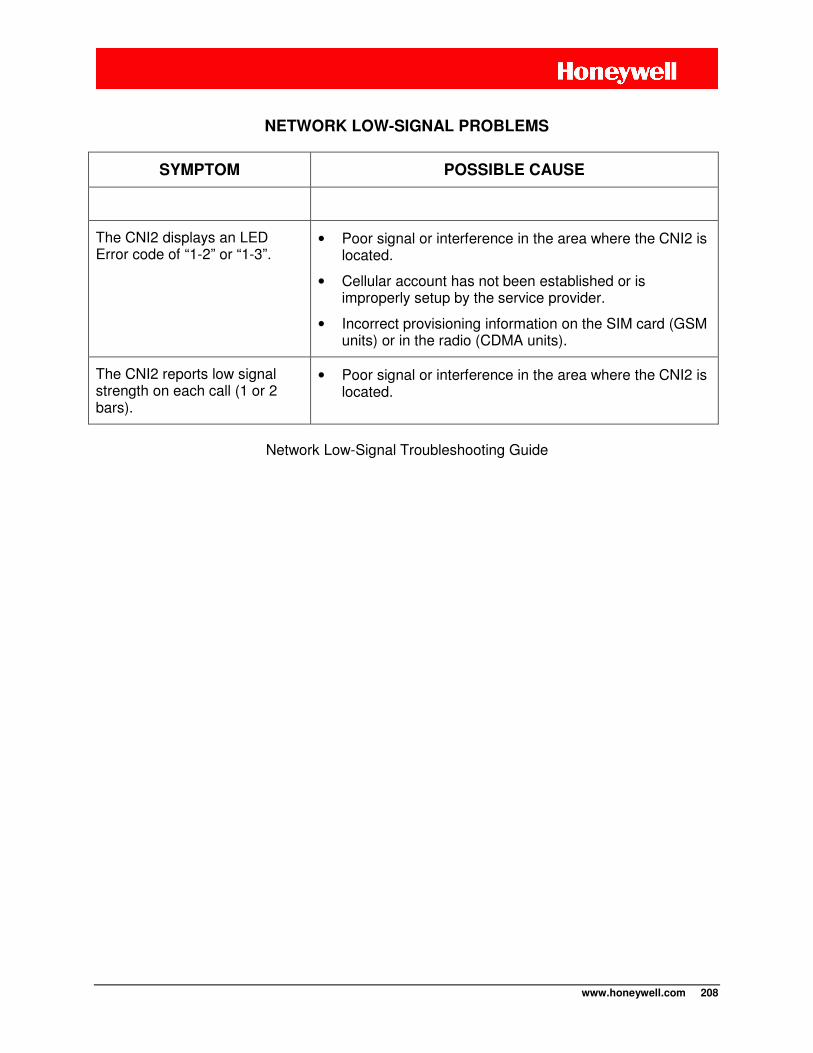
www.honeywell.com 208
NETWORK LOW-SIGNAL PROBLEMS
SYMPTOM POSSIBLE CAUSE
The CNI2 displays an LED Error code of “1-2” or “1-3”.
• Poor signal or interference in the area where the CNI2 is located.
• Cellular account has not been established or is improperly setup by the service provider.
• Incorrect provisioning information on the SIM card (GSM units) or in the radio (CDMA units).
The CNI2 reports low signal strength on each call (1 or 2 bars).
• Poor signal or interference in the area where the CNI2 is located.
Network Low-Signal Troubleshooting Guide
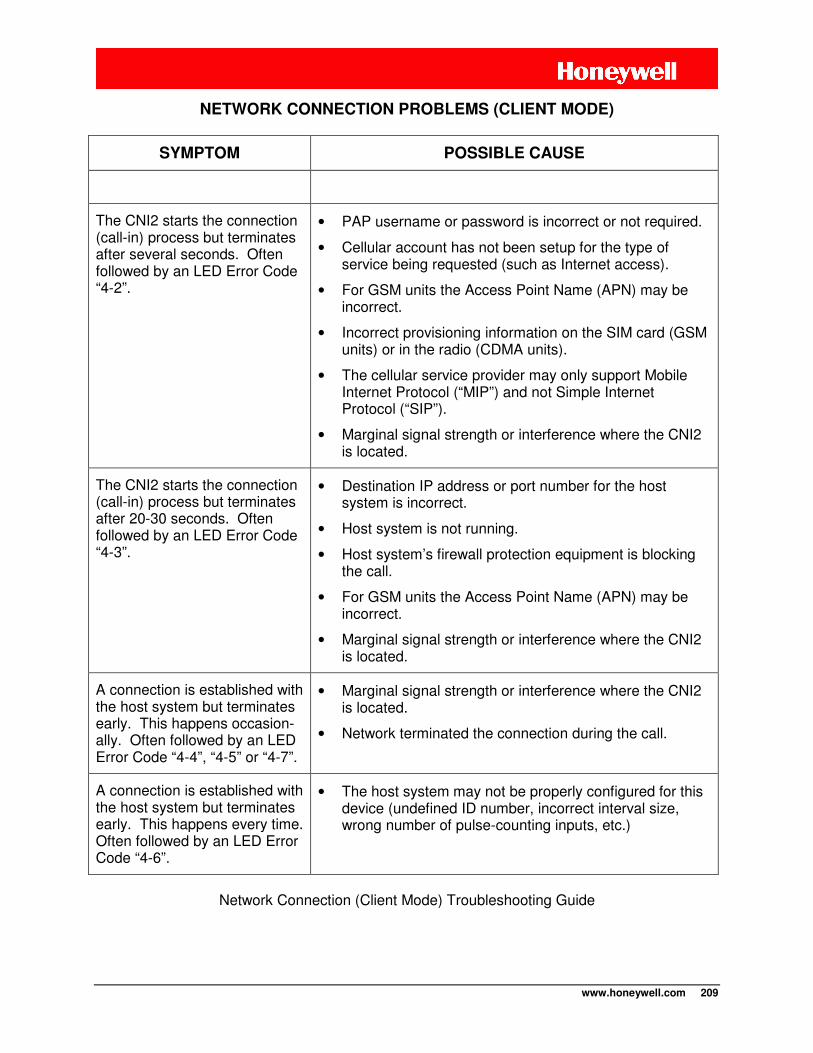
www.honeywell.com 209
NETWORK CONNECTION PROBLEMS (CLIENT MODE)
SYMPTOM POSSIBLE CAUSE
The CNI2 starts the connection (call-in) process but terminates after several seconds. Often followed by an LED Error Code “4-2”.
• PAP username or password is incorrect or not required.
• Cellular account has not been setup for the type of service being requested (such as Internet access).
• For GSM units the Access Point Name (APN) may be incorrect.
• Incorrect provisioning information on the SIM card (GSM units) or in the radio (CDMA units).
• The cellular service provider may only support Mobile Internet Protocol (“MIP”) and not Simple Internet Protocol (“SIP”).
• Marginal signal strength or interference where the CNI2 is located.
The CNI2 starts the connection (call-in) process but terminates after 20-30 seconds. Often followed by an LED Error Code “4-3”.
• Destination IP address or port number for the host system is incorrect.
• Host system is not running.
• Host system’s firewall protection equipment is blocking the call.
• For GSM units the Access Point Name (APN) may be incorrect.
• Marginal signal strength or interference where the CNI2 is located.
A connection is established with the host system but terminates early. This happens occasion-ally. Often followed by an LED Error Code “4-4”, “4-5” or “4-7”.
• Marginal signal strength or interference where the CNI2 is located.
• Network terminated the connection during the call.
A connection is established with the host system but terminates early. This happens every time. Often followed by an LED Error Code “4-6”.
• The host system may not be properly configured for this device (undefined ID number, incorrect interval size, wrong number of pulse-counting inputs, etc.)
Network Connection (Client Mode) Troubleshooting Guide
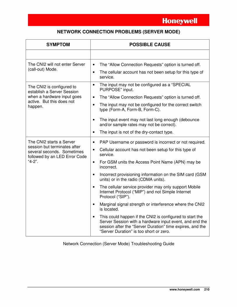
www.honeywell.com 210
NETWORK CONNECTION PROBLEMS (SERVER MODE)
SYMPTOM POSSIBLE CAUSE
The CNI2 will not enter Server (call-out) Mode.
• The “Allow Connection Requests” option is turned off.
• The cellular account has not been setup for this type of service.
The CNI2 is configured to establish a Server Session when a hardware input goes active. But this does not happen.
• The input may not be configured as a “SPECIAL PURPOSE” input.
• The “Allow Connection Requests” option is turned off.
• The input may not be configured for the correct switch type (Form-A, Form-B, Form-C).
• The input event may not last long enough (debounce
and/or sample rates may not be correct).
• The input is not of the dry-contact type.
The CNI2 starts a Server session but terminates after several seconds. Sometimes followed by an LED Error Code “4-2”.
• PAP Username or password is incorrect or not required.
• Cellular account has not been setup for this type of service.
• For GSM units the Access Point Name (APN) may be incorrect.
• Incorrect provisioning information on the SIM card (GSM units) or in the radio (CDMA units).
• The cellular service provider may only support Mobile Internet Protocol (“MIP”) and not Simple Internet Protocol (“SIP”).
• Marginal signal strength or interference where the CNI2 is located.
• This could happen if the CNI2 is configured to start the Server Session with a hardware input event, and end the session after the “Server Duration” time expires, and the “Server Duration” is too short or zero.
Network Connection (Server Mode) Troubleshooting Guide
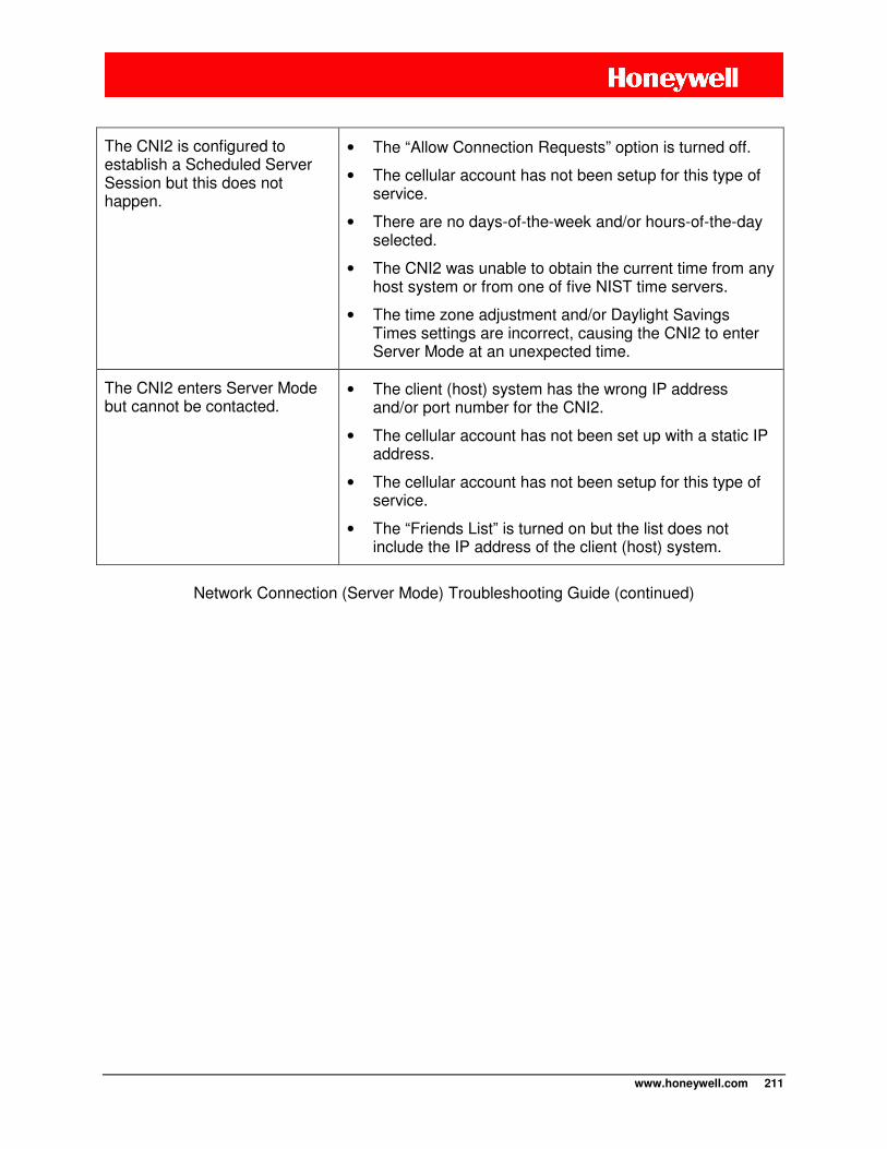
www.honeywell.com 211
The CNI2 is configured to establish a Scheduled Server Session but this does not happen.
• The “Allow Connection Requests” option is turned off.
• The cellular account has not been setup for this type of service.
• There are no days-of-the-week and/or hours-of-the-day selected.
• The CNI2 was unable to obtain the current time from any host system or from one of five NIST time servers.
• The time zone adjustment and/or Daylight Savings Times settings are incorrect, causing the CNI2 to enter Server Mode at an unexpected time.
The CNI2 enters Server Mode but cannot be contacted.
• The client (host) system has the wrong IP address and/or port number for the CNI2.
• The cellular account has not been set up with a static IP address.
• The cellular account has not been setup for this type of service.
• The “Friends List” is turned on but the list does not include the IP address of the client (host) system.
Network Connection (Server Mode) Troubleshooting Guide (continued)

www.honeywell.com 212
SERIAL PORT
SYMPTOM POSSIBLE CAUSE
The CNI2 cannot establish communications with the device attached to its serial port.
• Incorrect baud rate, parity, stop bits or character length.
• Incorrect serial port selected.
• “Allow Transparent” option is turned off.
• Configuration jumper JP3-3 is not in the correct location for this type of serial connection.
• Some serial devices need a special response or keyword to allow the communications to begin. For instance a “CONNECT” message. The CNI2 may not be properly configured to send this type of message to the device.
• The handshaking selection may not be proper for the device.
The CNI2 will not accept a dial-out (“ATD”) command from the device attached to its serial port.
• In most applications the CNI2 will enter a low-power sleep mode between calls. If the CNI2 is brought out of this mode by the reception of data from the serial device, it may miss the first character of the ATD command and therefore not recognize it as an ATD command. The serial device should be configured to repeat the command within 15 seconds, or precede the command with one or two “AT” commands.
• Configuration jumper JP3-2 is not installed in the correct location for the CNI2 to recognize incoming data from the serial device.
• Configuration jumper JP3-3 is not in the correct location for this type of serial connection.
The CNI2 accepts a dial-out (“ATD”) command from the device attached to its serial port but cannot connect to the host system. Often followed by an LED Error Code “4-3”.
• The destination phone number or IP address/port number included in the ATD command may be wrong or improperly formatted.
• Host system is not running.
• Host system’s firewall protection equipment is blocking the call.
Serial Port Troubleshooting Guide
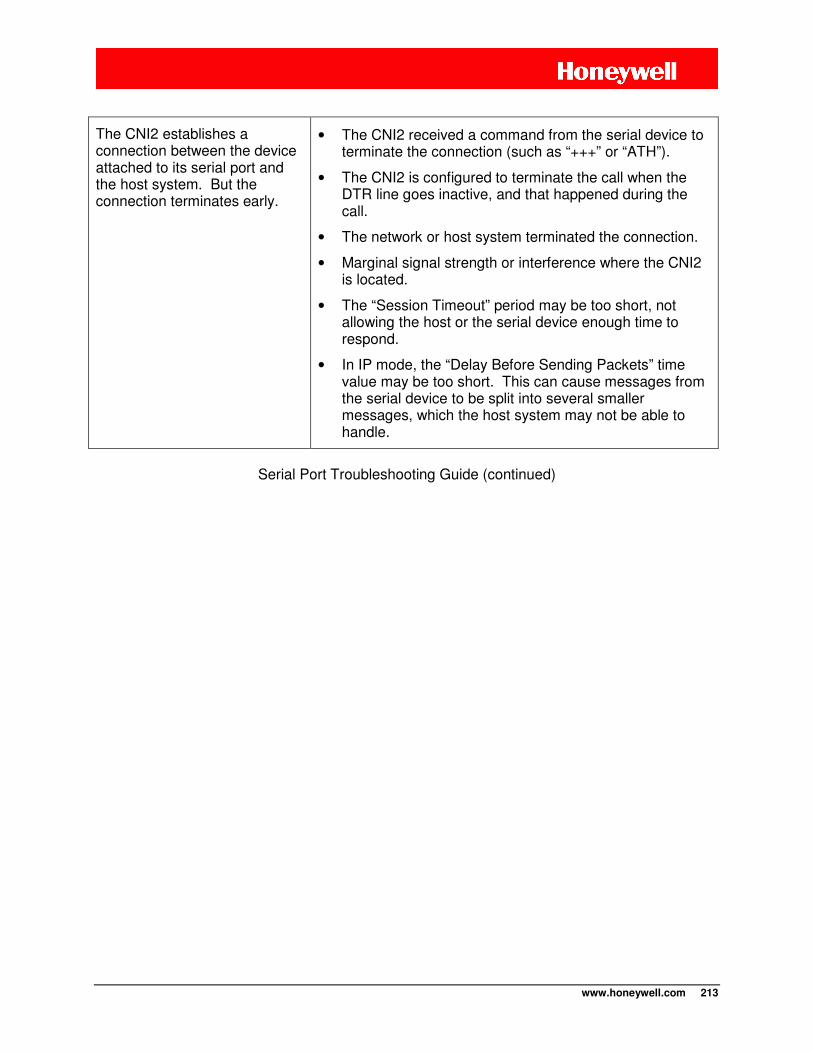
www.honeywell.com 213
The CNI2 establishes a connection between the device attached to its serial port and the host system. But the connection terminates early.
• The CNI2 received a command from the serial device to terminate the connection (such as “+++” or “ATH”).
• The CNI2 is configured to terminate the call when the DTR line goes inactive, and that happened during the call.
• The network or host system terminated the connection.
• Marginal signal strength or interference where the CNI2 is located.
• The “Session Timeout” period may be too short, not allowing the host or the serial device enough time to respond.
• In IP mode, the “Delay Before Sending Packets” time value may be too short. This can cause messages from the serial device to be split into several smaller messages, which the host system may not be able to handle.
Serial Port Troubleshooting Guide (continued)

www.honeywell.com 214
www.honeywell.com 215
BATTERY REPLACEMENT
Life of the battery pack is dependent on several factors such as the number of calls made per day or month, the number of inputs attached, etc. Some users may prefer to wait for a low battery alarm to be reported before sending a person the field to replace the pack. Others may prefer to replace the battery pack on a fixed schedule, regardless of the remaining battery capacity. This approach has several trade-offs, which include higher reliability and less down time but at the extra expense of purchasing batteries more often. There could potentially be lower labor costs for the field technician if he or she is also servicing other nearby equipment. Replacement of internal battery packs is quick and convenient by pressing left-wards on the large plastic tab and pulling the pack out. Take care to not lose grip of the battery pack while disconnecting the power connector from the CNI2 board. Battery replacement intervals will vary depending on frequency of calls and the battery type (lithium vs. alkaline).
CLEANING AND CHEMICAL COMPATIBILITY LIST
Acceptable cleaning and degreasing agents for the external surface of the CNI2 enclosure: Mineral Spirits, Isopropyl Alcohol, mild soap and water, VM&P Naptha, Fantastik, Windex, Joy dishwashing soap, Top Job, Mr. Clean, Formula 409.
MAINTENANCE CHECKLIST A regular program of performing inspection and maintenance on a CNI2 when in the field offers the following benefits:
a) Longer total service life of the product b) More reliability, less downtime c) Decreased risk of potential hazards caused by deteriorating wires, etc.
Each user will have their own internal policies for maintenance / inspection of equipment, which includes regulators, turbine meters, pipelines, and electrical equipment to name just a few. Some of these policies and schedules are dictated by statutory requirements that must be met, and some are based on internal corporate experience where the benefits of regular maintenance have become apparent.
Physical inspection of the equipment is also necessary, with the following list provided as a starting point:
1) Check the condition and integrity of the cables leading into the CNI2. Long term exposure to the elements may cause the cable jacket to become brittle. Physical damage from lawn equipment or similar equipment is not uncommon. Maintaining the cable in good condition will enhance the reliability and safety of the system.
2) Check for evidence of tampering, vandalism, or unintended impact damage. If someone
has attempted to tamper with the unit, there may be evidence of screwdriver pry marks on the door of the enclosure. Such a unit should be serviced immediately, since the
MAINTENANCE
www.honeywell.com 216
water ingress resistance of the CNI2 will have been compromised, which reduces the overall safety and reliability levels.
3) If the enclosure is opened for service reasons, check for any evidence of moisture
accumulation, mold, or cable corrosion. Inspect the enclosure gasket for evidence of small cracks, which would indicate that it should be replaced. It is normal however that a gasket will have a slight indent mark due to the compression from the lid. Insects will normally not be an issue so long as the cable glands were properly tightened during the initial install. Performing this periodic service step increases potential service life, reliability, and maintains hazardous area safety.
4) Where the CNI2 has the external antenna connection option, this should be inspected
for corrosion. Normally it is best policy to completely seal the connector area with a suitable sealant.
5) Cleaning / decontamination of the enclosure’s exterior is normally not necessary, except
to address obvious issues such as a bird or hornet nests atop the unit. If it is desired to clean the surface for better label visibility, then a cloth heavily dampened with water or aspray cleaner such as Clorox Formula 409 will work.
WARNING – Explosion Hazard
The plastic enclosure’s surfaces are potential sources for static charge accumulation when rubbed with a dry cloth. This could result in static discharge, which would then
lead to hazardous gas ignition / explosion.
Always use a damp cloth when cleaning the outside surface of a CNI2 enclosure.
Additional service is normally not required, unless it becomes necessary to swap out a CNI2 or diagnose problems. Precautionary guidelines when using multi-meters and other diagnostic equipment while inside a potential hazardous gas environment apply here.
WARNING – Explosion Hazard
Do not make or break connections while the circuit is alive unless you are in an area known to be non-hazardous. This includes both field wiring connections and battery
pack replacement.
If there are any operational problems directly related to the electronics of the CNI2, then it is often times more convenient to swap the unit out with a spare and then later make a determination in the repair shop as to whether it should be returned to Honeywell for service.

www.honeywell.com 217
Any electronics device contains components sensitive to ESD (electrostatic discharge). For example people experience up to 35kV ESD, typically while walking on a carpet in low humidity environments. In the same manner many electronic components can be damaged by less than 1000 volts of ESD. For this reason you must observe the following handling precautions when servicing this equipment:
1) Always wear a conductive wrist strap.
2) Eliminate static generators (plastics, Styrofoam, and so on) in the work area.
3) Remove nylon or polyester jackets, roll up long sleeves, and remove or tie back loose hanging neckties, jewelry, and long hair.
4) Store and transport all static sensitive components in ESD protective containers.
5) Disconnect all power from the unit before ESD sensitive components are removed or inserted, unless noted.
6) Use a static safeguarded workstation, which can be set up by using an anti-static kit (Motorola part number 0180386A82). This kit includes a writes strap, two ground cords, a static control tablemat, and a static control floor mat. The Motorola part number for a replacement wrist strap that connects to the tablemat is 4280385A59.
7) When anti-static facilities are unavailable, use the following technique to minimize the chance of damaging the equipment:
8) Let the static sensitive component rest on a conductive surface when you are not holding it.
9) When setting down or picking up the static sensitive component, make skin contact with a conductive work surface first and maintain this contact while handling the component.
10) If possible, maintain relative humidity of 70-75% in development labs and service shops. Less humidity is more conducive towards static charge buildup and subsequent discharge.
ESD HANDLING PRECAUTIONS
www.honeywell.com 218
HAZARDOUS AREA CLASSIFICATION (NORTH AMERICAN CLASS I, DIVISION 2)
The CNI2 is approved for use in hazardous gas environments, Class I, Division 2, Group-D (methane, propane, butane), temperature class T4. Equivalent ratings as defined by the NEC / NFPA70 article 501 are Class I, Zone 2, Group IIA. Prior to installing equipment, always confirm the safety ratings are appropriate by checking the label affixed to the product. The NEC / NFPA-70 text provides important guidance for proper electrical wiring methods, grounding, safety area classifications etc. Articles 500-505 are of particular relevance to hazardous gas environments. Control drawing 40-5084 defines the exact parameters related to all permissible inputs, outputs, battery options, and site information. This drawing is also available in electronic PDF format free of charge upon request. Contact your local Product Support Specialist for assistance. NOTE: The hazardous ratings label affixed to the product should be relied upon as being the most reliable source of information concerning approved ratings. This manual and similar texts or brochures may be updated periodically to reflect new product improvements or additional certifications that have been obtained.
CONTROL DRAWINGS - HAZARDOUS AREA
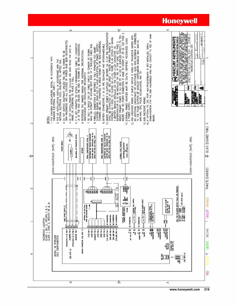
www.honeywell.com 219
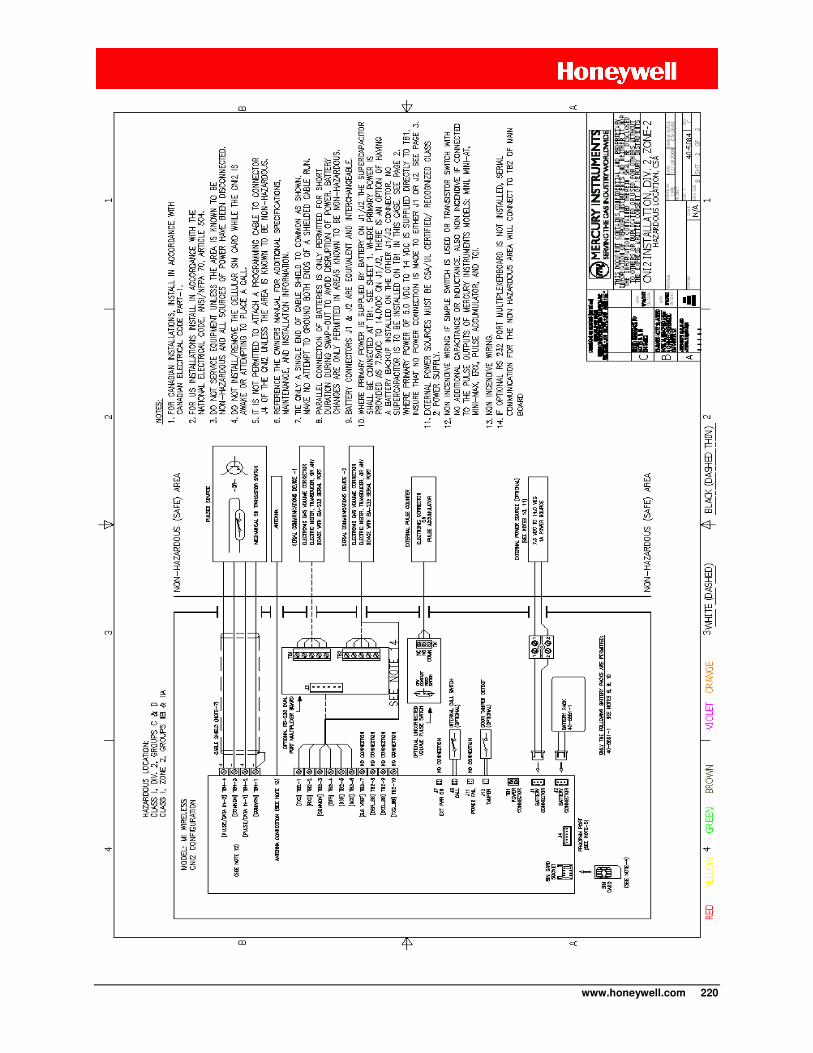
www.honeywell.com 220
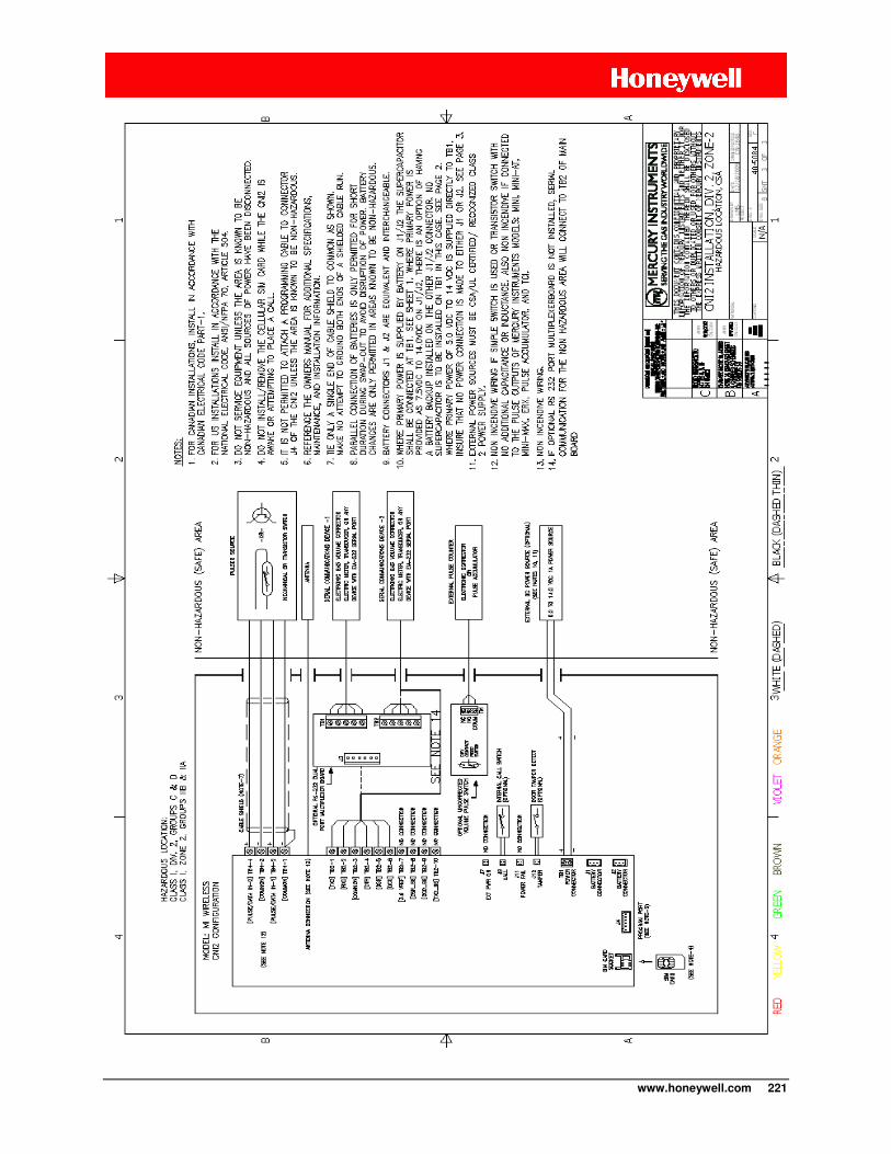
www.honeywell.com 221
www.honeywell.com 222
SPECIFICATIONS
CERTIFICATIONS
• Measurement Canada (metrology) • CSA: Class I, Div 2, Group-D Hazardous Gas Areas • FCC, CFR, Title 47, Chapter I, Part 15 Subpart B (USA) ICES-003,Issue 4, 2004 (Canada)
Itertek Report #100101158ATL-001 • FCC Parts 22, 24 IHDT56HQ1 (G24-L) and IHDP56JE1 (C24) • PTCRB for the North American GSM network
CELLULAR CARRIER CERTIFICATIONS The CNI2 is permitted to operate with the following cellular network carriers.
• Aeris, CDMA / 1XRTT • Rogers, GSM / GPRS • T-Mobile, GSM / GPRS • AT&T, GSM / GPRS • Sprint, CDMA/ 1XRTT • Verizon Wireless, CDMA / 1XRTT
www.honeywell.com 223
MECHANICAL
Operational Temperature range
-22 °F to 158 °F (-30 °C to 70 °C)
Environmental Ratings Enclosure is equivalent in protection to NEMA 3R, suitable for indoor or outdoor use, providing a degree of protection against solid foreign objects, and to provide a degree of protection with respect to harmful effects due to ingress of rain, sleet, snow or formation of ice on the enclosure. Fiberglass reinforced polycarbonate enclosure is resistant to the effects of long term UV exposure.
Enclosure Mounting Various mounting options are available, including flat wall, pipe clamps, or direct meter mount. Contact a Honeywell Product Support Specialist to discuss your application and the most appropriate solution. Several configurations are shown near the beginning of this document.
Mounting Direction To maintain integrity of the enclosure protection rating, the enclosure must be mounted in a vertical configuration.
Humidity Range 5 - 95% R.H. If the product is to be retained in storage for any length of time, it is recommended that the humidity range be maintained between 10 - 70% R.H., non-condensing.
Cable Glands A maximum of three cable glands can be populated onto the enclosure. The actual number of supplied glands will vary depending on the configuration ordered and whether the CNI2 is supplied with or without an index.
Weight of CNI2 with Wall Mount Option: (w/o batteries) 2.4 pounds
Weight of CNI2 with Meter Mount Option: (w/o batteries) 3.4 pounds
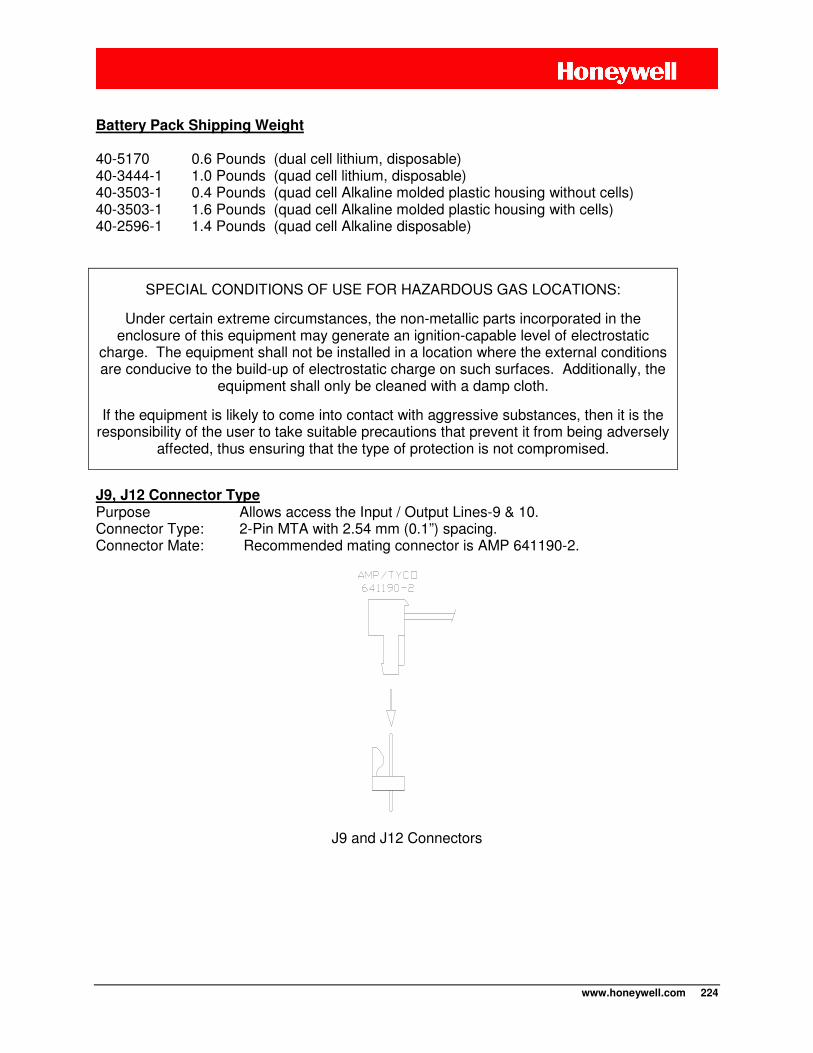
www.honeywell.com 224
Battery Pack Shipping Weight
40-5170 0.6 Pounds (dual cell lithium, disposable) 40-3444-1 1.0 Pounds (quad cell lithium, disposable) 40-3503-1 0.4 Pounds (quad cell Alkaline molded plastic housing without cells) 40-3503-1 1.6 Pounds (quad cell Alkaline molded plastic housing with cells) 40-2596-1 1.4 Pounds (quad cell Alkaline disposable)
SPECIAL CONDITIONS OF USE FOR HAZARDOUS GAS LOCATIONS:
Under certain extreme circumstances, the non-metallic parts incorporated in the enclosure of this equipment may generate an ignition-capable level of electrostatic
charge. The equipment shall not be installed in a location where the external conditions are conducive to the build-up of electrostatic charge on such surfaces. Additionally, the
equipment shall only be cleaned with a damp cloth.
If the equipment is likely to come into contact with aggressive substances, then it is the responsibility of the user to take suitable precautions that prevent it from being adversely
affected, thus ensuring that the type of protection is not compromised.
J9, J12 Connector Type Purpose Allows access the Input / Output Lines-9 & 10. Connector Type: 2-Pin MTA with 2.54 mm (0.1”) spacing. Connector Mate: Recommended mating connector is AMP 641190-2.
J9 and J12 Connectors
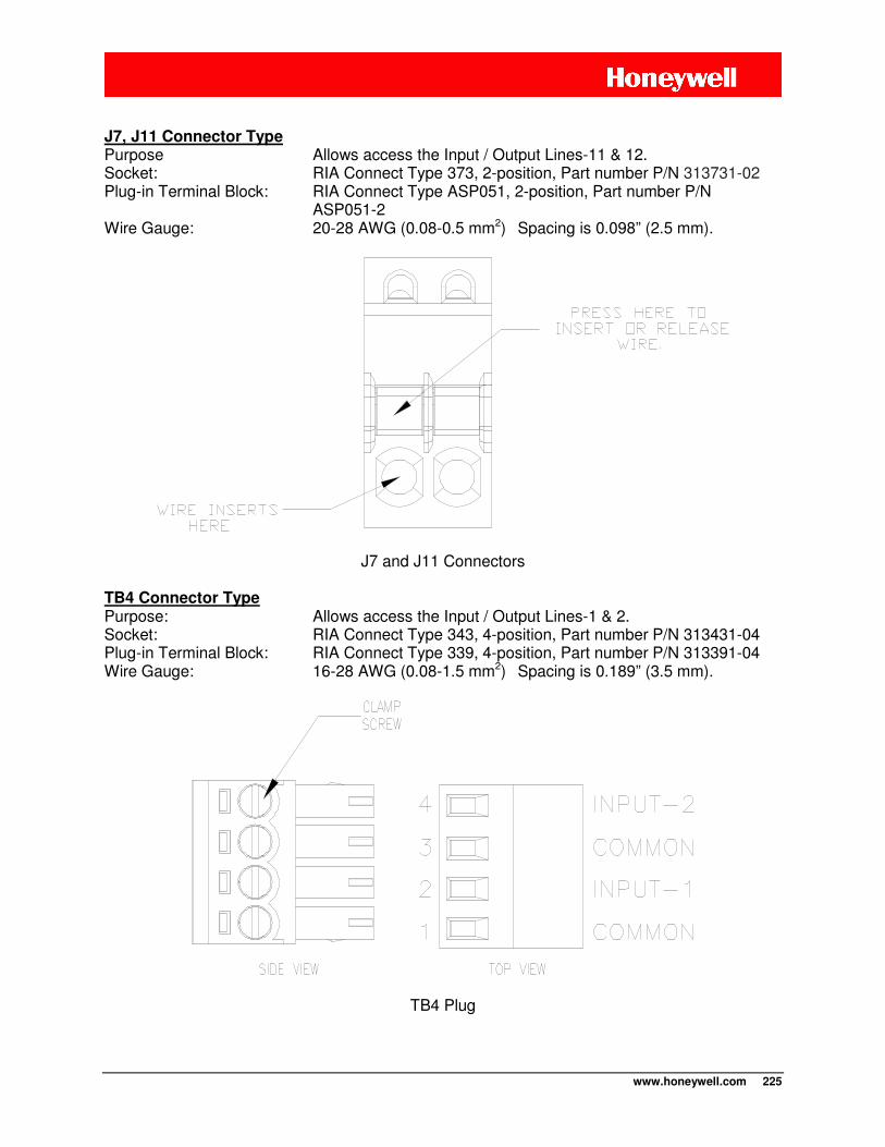
www.honeywell.com 225
J7, J11 Connector Type Purpose Allows access the Input / Output Lines-11 & 12. Socket: RIA Connect Type 373, 2-position, Part number P/N 313731-02 Plug-in Terminal Block: RIA Connect Type ASP051, 2-position, Part number P/N
ASP051-2 Wire Gauge: 20-28 AWG (0.08-0.5 mm2) Spacing is 0.098” (2.5 mm).
J7 and J11 Connectors TB4 Connector Type Purpose: Allows access the Input / Output Lines-1 & 2. Socket: RIA Connect Type 343, 4-position, Part number P/N 313431-04 Plug-in Terminal Block: RIA Connect Type 339, 4-position, Part number P/N 313391-04 Wire Gauge: 16-28 AWG (0.08-1.5 mm2) Spacing is 0.189” (3.5 mm).
TB4 Plug
www.honeywell.com 226
ELECTRICAL - POWER
Battery Voltage: (without load applied) Lithium = 6.9 Volts Alkaline = 6.0 Volts
Approved Battery Pack Assemblies 40-5170 Dual cell lithium, disposable configuration. 40-3444-1 Quad cell lithium, disposable configuration. 40-3503-1 Quad cell alkaline molded plastic assembly (replaceable cells). 40-2596-1 Quad cell alkaline disposable configuration.
Battery Life Highly dependent upon number of pulse counting inputs, cellular call durations, and the number of calls made per day or month. Due to the number of potential variables, this is difficult to predict for all circumstances. Mercury can provide reference information that details a single “typical” site and the expected life based on this example case.
CAUTION: Disposal of lithium battery cells is strictly regulated in most areas as hazardous waste material.
Consult your regional waste disposal authority to ensure full compliance with legal statutes when disposing of cells.
WARNING: Transport of primary cell lithium batteries (even when fully discharged) is strictly forbidden on
passenger aircraft. Cargo shipment of batteries via UPS, FedEx, etc., requires approved shipping containers, packing methods, MSDS information, and other paperwork to be included.
Current Requirements during Transmission GSM, HSPA: During transmission the average current is 300 mA but peak currents can be as high as 2.0 amps for a duration of 0.5 milliseconds every 4.5 milliseconds.
iDEN: During transmission the average current is 250 mA but peak currents can be as high as 1.2 amps for a duration of 15 milliseconds every 90 milliseconds.
CDMA: During transmission the maximum current draw is 800 mA.
Sleep current (data logger mode, no communications option boards) < 350 µA.

www.honeywell.com 227
Boost Capacitor Connects to the TB1 terminal block and assists the battery pack during peak current events, usually during radio transmission. Low-Voltage Detector Measured at the TB1, J1 and J2 power connectors, which ever has the highest voltage. A user-selectable alarm point in the range of 0.1 – 28 Vdc can be used to report low-voltage situations. Power Input #3 (TB1) Connector Type Screw terminal, 5.08 mm (0.2”) spacing. 90º entry. 14-26 AWG (0.14 – 1.5 mm2) wire size. Maximum torque is 0.6 Nm (5.3 lbs.-in). See next illustration for polarity. Power Input #1 & #2 (J1 and J2) Connector Type 3-pin JST B3B-XH-A. Recommended mating connector is JST XHP-3 connector housing with two SXH-001T-P0.6 female contacts. See next illustration for polarity.
Power Input Connector Polarities

www.honeywell.com 228
ELECTRICAL - GENERAL
Pulse Count Retention Memory User-selectable between 32K (which is actually 32768 bytes) or 60K (which is actually 61440 bytes). Total number of records that can be stored varies with the configuration. As a Metretek SIP each pulse-counting channel requires 2 bytes per record. As a Mercury Mini-Max or Pulse Accumulator the total number of records depends on the number of audit trail items being requested. See the Chapter entitled “Mercury Emulation” for exact details.
Flash Program Memory 116k bytes. Holds operating system and configuration values. Static RAM Memory 8k bytes.
Clocks Main frequency: 15.360 MHz Time keeping frequency: 32.768 kHz “Sleep” frequency: 200 kHz nominal (internal oscillator), bursting to 15 MHz during input sample periods in data logger mode. Logic Supply Voltage 3.3V nominal. This supply is also available on Expansion Port #1 (J8) and Expansion Port #2 (J3) but is intended to be used as a reference and not as a power source. Auxiliary Supply Voltage 3.6V, 1.5A max. Normally only used to power the cellular radio or a potential option board that might be developed in the future. It is normally under the control of the processor. This supply is also available on Expansion Port #2 (J3), the serial port terminal block (TB2) and the middle pins of the J1 and J2 power input connectors. These connections are current-limited with a replaceable 250 mA fuse (Littelfuse 251-250 or equivalent).
www.honeywell.com 229
ELECTRICAL – DIGITAL OUTPUTS
Number of outputs Six outputs are available if not being used as inputs. Two are available on the TB2 terminal block, 4 are available on the J7, J9, J11 and J12 connectors. Output Configuration Push-pull, +3.3V, 2 mA max. Programmable as normally low or normally high. Source resistance 100Ω Operating Modes Up to three outputs can be changed remotely using DC-2009® data collection system and with the CNI2 configured as a Metretek SIP. Any output (J7) can be configured to follow an input. One output can be configured to control external power sources. Recommended Output Cable Alpha 6300/4, Belden 9534, or equivalent having less than 100pF/ft capacitance. This cable type is 24awg, shielded, and has a PVC jacket. Terminate only one end of the cable shield to signal common or ground. Maximum cable length run should not exceed 1000 feet. Other cable types or gauges can be also be used as long as careful consideration is given to suitable wiring practices and performance.
www.honeywell.com 230
ELECTRICAL – DIGITAL INPUTS Number of inputs Six inputs are available if not being used as outputs. Two are available on the TB2 terminal block, 4 are available on the J7, J9, J11 and J12 connectors. Input Configuration Form-A or Form-B (independently configurable). Two inputs can be paired for Form-C operation. Input rate (sampling mode) 10 Hz maximum Minimum input pulse width (sampling mode) 25 mS. Sample rate (sampling mode) 1 – 50 samples per second (applies to all 6 inputs). Sample rate is user-selectable. A value of 0 selects edge-detection mode. Debounce Count (sampling mode) Number of samples needed to declare an input valid. This is user-selectable and each input is independently configurable. For instance if the sample rate is 4 samples per second, and the debounce value is set to 20, then the signal must be in the same state for 20 consecutive samples to be declared valid, which would be for a period of 5 seconds. Debounce values are ignored in edge-detection mode. Input rate (edge-detection mode) TBD Hz maximum Minimum pulse width (edge-detection mode) TBD mS. Wetting current per input 33 µA nominal. Wetting voltage +3.3V nominal. Input resistance 100Ω Recommended Input Cable Alpha 6300/4, Belden 9534, or equivalent having less than 100pF/ft capacitance. This cable type is 24awg, shielded, and has a PVC jacket. Terminate only one end of the cable shield to signal common or ground. Maximum cable length run should not exceed 1000 feet. Other cable types or gauges can be also be used as long as careful consideration is given to suitable wiring practices and performance.
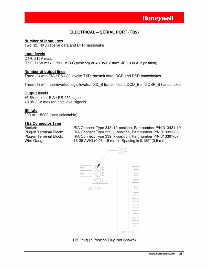
www.honeywell.com 231
ELECTRICAL – SERIAL PORT (TB2)
Number of input lines Two (2), RXD receive data and DTR handshake Input levels
DTR: ±15V max. RXD: ±15V max (JP3-3 in B-C position) or +3.3V/0V max JP3-3 in A-B position) Number of output lines Three (3) with EIA / RS-232 levels: TXD transmit data, DCD and DSR handshakes Three (3) with non-inverted logic levels: TXD_B transmit data DCD_B and DSR_B handshakes Output levels
±5.5V max for EIA / RS-232 signals. +3.3V / 0V max for logic-level signals. Bit rate 300 to 115200 (user-selectable)
TB2 Connector Type Socket: RIA Connect Type 343, 10-position, Part number P/N 313431-10 Plug-in Terminal Block: RIA Connect Type 339, 3-position, Part number P/N 313391-03 Plug-in Terminal Block: RIA Connect Type 339, 7-position, Part number P/N 313391-07 Wire Gauge: 16-28 AWG (0.08-1.5 mm2) Spacing is 0.189” (3.5 mm).
TB2 Plug (7-Position Plug Not Shown)
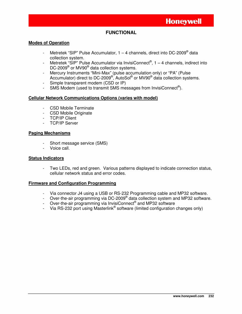
www.honeywell.com 232
FUNCTIONAL
Modes of Operation
- Metretek “SIP” Pulse Accumulator, 1 – 4 channels, direct into DC-2009® data collection system.
- Metretek “SIP” Pulse Accumulator via InvisiConnect®, 1 – 4 channels, indirect into DC-2009® or MV90® data collection systems.
- Mercury Instruments “Mini-Max” (pulse accumulation only) or “PA” (Pulse Accumulator) direct to DC-2009®, AutoSol® or MV90® data collection systems.
- Simple transparent modem (CSD or IP) - SMS Modem (used to transmit SMS messages from InvisiConnect®).
Cellular Network Communications Options (varies with model)
- CSD Mobile Terminate - CSD Mobile Originate - TCP/IP Client - TCP/IP Server
Paging Mechanisms
- Short message service (SMS) - Voice call.
Status Indicators
- Two LEDs, red and green. Various patterns displayed to indicate connection status,
cellular network status and error codes. Firmware and Configuration Programming
- Via connector J4 using a USB or RS-232 Programming cable and MP32 software. - Over-the-air programming via DC-2009® data collection system and MP32 software. - Over-the-air programming via InvisiConnect® and MP32 software - Via RS-232 port using Masterlink® software (limited configuration changes only)
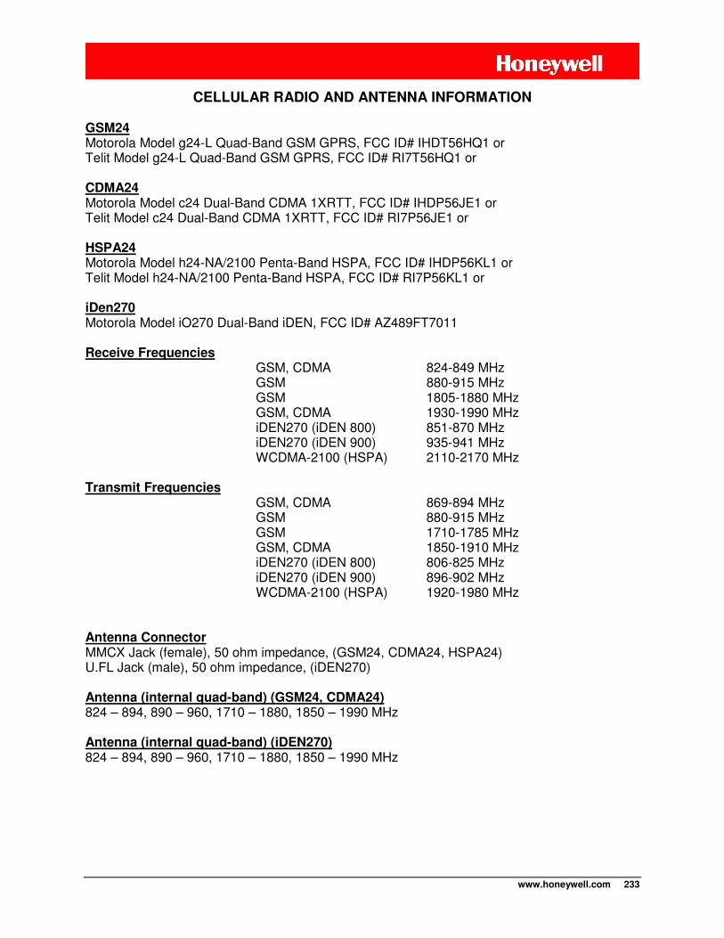
www.honeywell.com 233
CELLULAR RADIO AND ANTENNA INFORMATION
GSM24 Motorola Model g24-L Quad-Band GSM GPRS, FCC ID# IHDT56HQ1 or Telit Model g24-L Quad-Band GSM GPRS, FCC ID# RI7T56HQ1 or CDMA24 Motorola Model c24 Dual-Band CDMA 1XRTT, FCC ID# IHDP56JE1 or Telit Model c24 Dual-Band CDMA 1XRTT, FCC ID# RI7P56JE1 or HSPA24 Motorola Model h24-NA/2100 Penta-Band HSPA, FCC ID# IHDP56KL1 or Telit Model h24-NA/2100 Penta-Band HSPA, FCC ID# RI7P56KL1 or iDen270 Motorola Model iO270 Dual-Band iDEN, FCC ID# AZ489FT7011 Receive Frequencies
GSM, CDMA 824-849 MHz GSM 880-915 MHz GSM 1805-1880 MHz GSM, CDMA 1930-1990 MHz iDEN270 (iDEN 800) 851-870 MHz iDEN270 (iDEN 900) 935-941 MHz WCDMA-2100 (HSPA) 2110-2170 MHz Transmit Frequencies
GSM, CDMA 869-894 MHz GSM 880-915 MHz GSM 1710-1785 MHz GSM, CDMA 1850-1910 MHz iDEN270 (iDEN 800) 806-825 MHz iDEN270 (iDEN 900) 896-902 MHz WCDMA-2100 (HSPA) 1920-1980 MHz
Antenna Connector MMCX Jack (female), 50 ohm impedance, (GSM24, CDMA24, HSPA24) U.FL Jack (male), 50 ohm impedance, (iDEN270) Antenna (internal quad-band) (GSM24, CDMA24) 824 – 894, 890 – 960, 1710 – 1880, 1850 – 1990 MHz Antenna (internal quad-band) (iDEN270) 824 – 894, 890 – 960, 1710 – 1880, 1850 – 1990 MHz
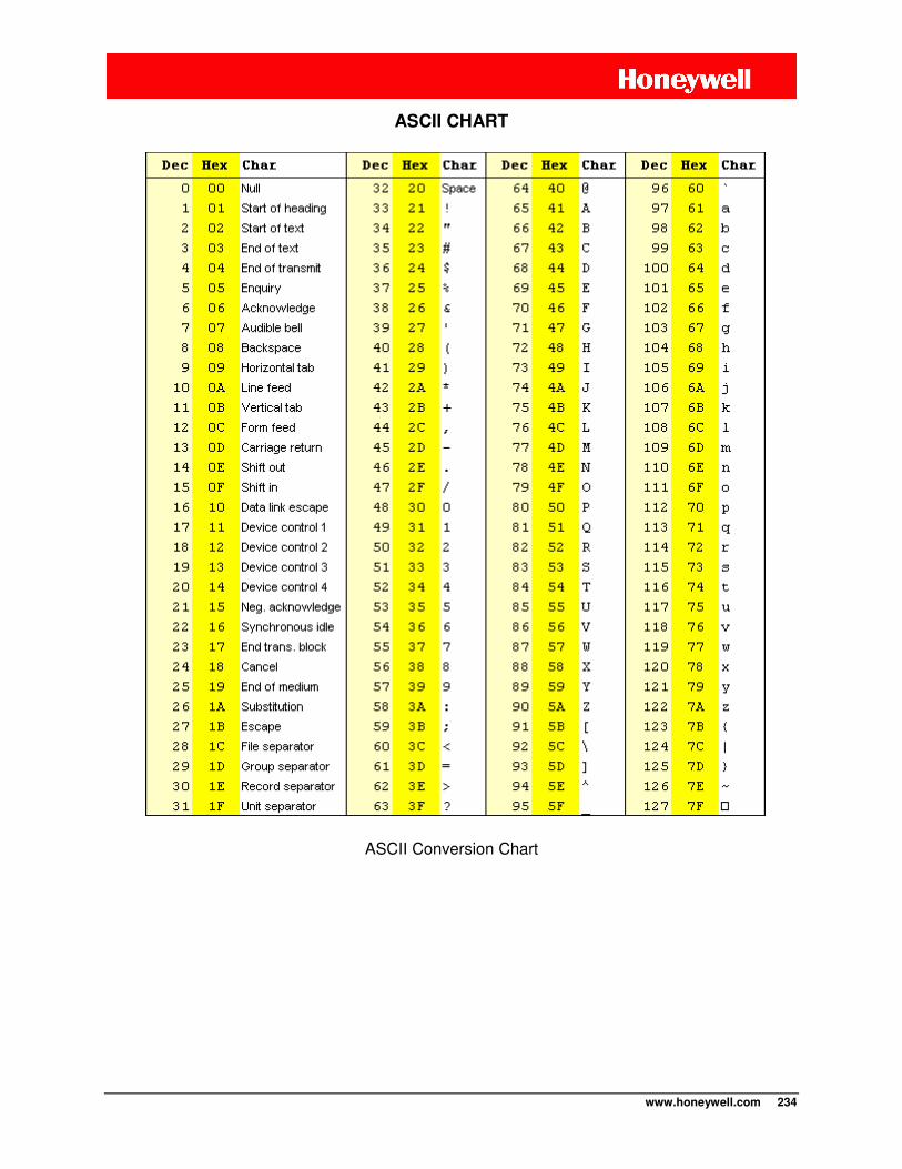
www.honeywell.com 234
ASCII CHART
ASCII Conversion Chart

www.honeywell.com 235
Find Out More:
To learn more about
Mercury Instruments products, contact your
Honeywell Process Solutions representative,
visit www.mercuryinstruments.com or call
513-272-1111.
Automation and Control Solutions
Honeywell Process Solutions
3940 Virginia Ave.
Cincinnati, OH 45227 MNL-CNI2-1
513-272-1111 April, 2012
www.honeywell.com © 2012 Honeywell