cellular coverage workgroup€¦ · hotel technology next generation solution architectures 25...
TRANSCRIPT

Cellular Coverage Workgroup
A Hotelier’s Guide to Cellular Coverage
Solutions
Solution Architectures
Version 1.00

Hotel Technology Next Generation Solution Architectures
25 January 2012 Version 1.00
Page 2
About HTNG
Hotel Technology Next Generation (HTNG) is a non-profit association with a mission to foster, through collaboration
and partnership, the development of next-generation systems and solutions that will enable hoteliers and their
technology vendors to do business globally in the 21st century; to be recognized as a leading voice of the global hotel
community, articulating the technology requirements of hotel companies of all sizes to the vendor community; and to
facilitate the development of technology models for hospitality that will foster innovation, improve the guest
experience, increase the effectiveness and efficiency of hotels, and create a healthy ecosystem of technology suppliers.
Copyright 2012, Hotel Technology Next Generation
All rights reserved.
No part of this publication may be reproduced, stored in a retrieval system, or transmitted, in any form or by any
means, electronic, mechanical, photocopying, recording, or otherwise, without the prior permission of the copyright
owner.
For any software code contained within this specification, permission is hereby granted, free-of-charge, to any person
obtaining a copy of this specification (the "Software"), to deal in the Software without restriction, including without
limitation the rights to use, copy, modify, merge, publish, distribute, sublicense, and/or sell copies of the Software, and
to permit persons to whom the Software is furnished to do so, subject to the above copyright notice and this
permission notice being included in all copies or substantial portions of the Software.
Manufacturers and software providers shall not claim compliance with portions of the requirements of any HTNG
specification or standard, and shall not use the HTNG name or the name of the specification or standard in any
statements about their respective product(s) unless the product(s) is (are) certified as compliant to the specification or
standard.
THE SOFTWARE IS PROVIDED "AS IS", WITHOUT WARRANTY OF ANY KIND, EXPRESS OR IMPLIED, INCLUDING BUT NOT
LIMITED TO THE WARRANTIES OF MERCHANTABILITY, FITNESS FOR A PARTICULAR PURPOSE, AND NON-INFRINGEMENT.
IN NO EVENT SHALL THE AUTHORS OR COPYRIGHT HOLDERS BE LIABLE FOR ANY CLAIM, DAMAGES, OR OTHER LIABILITY,
WHETHER IN AN ACTION OF CONTRACT, TORT OR OTHERWISE, ARISING FROM, OUT OF, OR IN CONNECTION WITH THE
SOFTWARE OR THE USE OR OTHER DEALINGS IN THE SOFTWARE.
Permission is granted for implementers to use the names, labels, etc. contained within the specification. The intent of
publication of the specification is to encourage implementations of the specification.
This specification has not been verified for avoidance of possible third-party proprietary rights. In implementing this
specification, usual procedures to ensure the respect of possible third-party intellectual property rights should be
followed.
The names Hotel Technology Next Generation and HTNG, and logos depicting these names, are trademarks of Hotel
Technology Next Generation. Permission is granted for implementers to use the aforementioned names in technical
documentation for the purpose of acknowledging the copyright and including the notice required above. All other use
of the aforementioned names and logos requires the permission of Hotel Technology Next Generation, either in written
form or as explicitly permitted for the organization’s members through the current terms and conditions of
membership.

Hotel Technology Next Generation Solution Architectures
25 January 2012 Version 1.00
Page 3
Table of contents 1 INTRODUCTION ............................................................................................................................................... 4
2 CELLULAR COVERAGE SOLUTIONS ......................................................................................................... 5
2.1 BASIC STRUCTURE AND ELEMENTS ................................................................................................................ 5 2.2 WIRELESS SERVICE PROVIDER (MNO) CONNECTIVITY .................................................................................. 6 2.3 COVERAGE SOLUTION COMPONENTS ............................................................................................................. 7 2.4 CELLULAR COVERAGE SOLUTION ARCHITECTURES ....................................................................................... 9
2.4.1 Active Systems ........................................................................................................................................ 9 2.4.2 Passive Systems ................................................................................................................................... 11 2.4.3 Hybrid Systems .................................................................................................................................... 11 2.4.4 Comparison of Cellular Coverage Solution Architectures .................................................................. 13
2.5 THE IMPACT OF 4G ON CELLULAR COVERAGE SOLUTIONS .......................................................................... 14

Hotel Technology Next Generation Solution Architectures
25 January 2012 Version 1.00
Page 4
1 Introduction
The cellular coverage best practices guide is intended to educate hoteliers and hospitality
technology management organizations recommending and supporting hotel properties on the
fundamentals of cellular coverage solutions. This guide includes an overview of the wireless
technologies supported by the cellular coverage solutions, available solutions and their
strengths and weaknesses, as well as design, installation and post-installations considerations.
This guide is intended to provide the hospitality IT or telecom manager with a thorough
overview and explains the process that hundreds of hotels have undertaken to select and
implement a cellular coverage solution. The information is presented in an uncomplicated
manner so that it may be quickly grasped for a high-level understanding, while still providing
enough depth to support a comprehensive understanding of the technologies, issues, and
concerns.
The contents of this guide are provided on the HTNG website in the following sections:
Solution Architectures
Design Considerations
Installation and Post-Installation Considerations
Glossary

Hotel Technology Next Generation Solution Architectures
25 January 2012 Version 1.00
Page 5
2 Cellular Coverage Solutions
Mobile Network Operators (MNOs) -- like AT&T, Sprint, T-Mobile and Verizon – have
experienced astonishing subscriber growth and today the majority of all cellular calls are made
in building. The expectations for both guests and staff have increased in parallel.
Typically, in order to keep up with customer demand, MNOs have grown their footprint by
constructing more cellular base transmit stations (often called cell sites). These are most often
recognized by the antennas mounted to a tower or building. Each cell site serves a predefined
area based on the traffic (number of customers) and the range of RF signal. When the range or
capacity is exceeded, another cell site must be strategically installed within the MNOs existing
network of cell sites.
However using a MNO cell-site to provide coverage inside a building is not always practical. For
a hotel property, there are many factors that determine practicality. Proximity to a cell site is
one major factor, but a property’s size and physical structure (e.g. steel, concrete, reflective
glass, etc.) also play a role by limiting RF penetration from a cell site. Additionally, the advent
of the smartphone and newer 4G technologies used by the MNOs, such as HSPA+ and LTE,
require very good coverage and depending on a cell site for in-building coverage is becoming is
less and less practical.
Cellular coverage solutions allow hoteliers to improve MNO coverage inside buildings by
deploying an antenna system directly in a facility.
Ubiquitous cell coverage for all carriers is becoming an expected amenity, much as high-speed
Internet access has become, and a cellular coverage solutions supporting multi-MNOs not only
ensures that hoteliers have a new amenity, but can also differentiate when it comes to revenue
opportunity, such as convention business.
2.1 Basic Structure and Elements
For cellular services, a MNO provides a signal source that enables cellular signals to be
communicated between the MNO network and a cellular coverage solution. The cellular
coverage solution distributes the cellular signals in-building and consists of a head-end that
interfaces to the MNO signal source, a cable transport, and antennas as shown in the diagram
below.

Hotel Technology Next Generation Solution Architectures
25 January 2012 Version 1.00
Page 6
2.2 Wireless Service Provider (MNO) Connectivity
The two most common signal sources for MNO connectivity are the bi-directional amplifier
(BDA) and base station (BTS). Each can provide the link to the MNO’s network and the MNO will
typically recommend the correct signal source for the facility, and then supply and maintain the
equipment. Additionally, ownership of the signal source typically remains with the MNO.
BTS systems come in various sizes and capacities but are typically larger and more expensive
than BDA. They require a T1 or other backhaul to the MNO’s call-switching center and more
HVAC resources than a BDA. A BTS, in essence, acts as miniature cell site. It is connected
directly to the MNO network and provides dedicated capacity to the facility through the cellular
coverage solution. With the increase in smartphones and data services this dedicated capacity
is becoming more critical and a BTS is being required by MNOs more often than a BDA.
Bi-directional amplifiers repeat signal from an outdoor cell site, thereby sharing the capacity of
the outside cell site. BDAs typically communicate with the outdoor cell site via a directional
antenna mounted on the roof of the building. RF signals from the cell site are received by the
antenna and passed to the BDA via a coaxial cable. The signals are amplified by the BDA and
then passed to the cellular coverage solution. Similarly, the return signals are passed by the
cellular coverage solution back to the BDA, where they are amplified for transport back to the
cell site outside the building.
While BDAs are lower in cost and typically much smaller than BTSs, several guidelines must be
adhered to with a BDA. First, a BDA should only be installed with prior consent and
coordination with the MNO (failure to do so may result in interference to the MNO network and
it is illegal to install a BDA without MNO prior consent to do so). Second, capacity should be
carefully examined. Since the BDA shares capacity with an outdoor cell site, if the outside cell
site is loaded with traffic outside the building, the ability to get acceptable coverage in the
Micro Cell
BDA
Antenna
Antenna
BTS
Carrier
Network
Hotel
Cell Phone
Cell Phone
Antenna
Cell Tower
Land Line
(T1's)

Hotel Technology Next Generation Solution Architectures
25 January 2012 Version 1.00
Page 7
facility may be limited. Next, a BDA with an off-air interface is more susceptible to interference
and to causing interference. Finally, depending on the type of cellular coverage solution, the
cost of a BDA cost can vary.
Note: A BDA is almost always used to communicate with the public safety network. These are
relatively un-complex for public safety in the 700 and 800 MHz bands, but may be quite
complex and expensive for public safety in the 150 or 450 MHz band.
IP base station. The advent of IP base stations in both the macro (outdoor) and indoor
environments provides WSPs with another solution to address coverage gaps and to increase
coverage capacity to meet the ever increasing demand of data traffic. The IP base stations are
easier to locate within a facility due to their smaller form factor while providing backhaul
savings due to improved bandwidth utilization. Again, this is another factor considered by the
WSP in determining the location-specific solution.
Ultimately there are tradeoffs between all of these solutions. Therefore, it is recommended,
and often required, that the WSP determine the correct signal source working with both the
facility and cellular coverage solution integrator. Once this is done, the WSP will provide
appropriate guidelines on connecting the signal source to the WSP network.
2.3 Coverage Solution Components
As mentioned previously, the cellular coverage solution itself consists of head-end, transport,
and re-distribution. The head-end places the RF signals from the MNO signal source into a
format suitable for distribution over the transport cabling and the re-distribution element (s)
(typically a small in-building antenna about the size of a smoke alarm).
While simple in concept, cellular coverage solutions can differ in many ways and the industry
has categorized them in the terms active, passive, and hybrid. These terms refer to the
electronics or lack of electronics in the head-end and transport. Before covering the
differences in these areas, it is useful to discuss some common elements - the transport
cabling and re-distribution elements.

Hotel Technology Next Generation Solution Architectures
25 January 2012 Version 1.00
Page 8
All cellular coverage solutions use cabling for transportation of RF signals from the head-end to
the re-distribution. These signals are transported in one of the following ways:
Coaxial cable, usually a half-inch in diameter, it has the largest diameter of any medium. Coax
is very high bandwidth and can support both high throughput and a wide variety of RF signals.
Coax is expensive to install relative to other transport mediums like CATV or CAT5/6, but with
lower RF signal loss, it may be used for distances up to 250 feet without any conversion
(electrical) or re-amplification of the RF signals.
Fiber, either single-mode or multi-mode optical fiber, can transport many frequencies on the
same fiber at distances greater than any other medium. While electrical to optical conversion is
required, fiber provides the greatest level of flexibility and scalability.
Mixed transport uses a combination of CAT5/6, CATV and/or fiber. The use of these mediums
can be attractive, as they may already exist in a facility. However, this transport presents high
loss to the RF signal and requires the RF signals be manipulated (usually down converted).
Manipulation can increase the cost of the coverage solution and may limit bandwidth, so
multiple services may require multiple or parallel systems.
Redistribution is most often accomplished via antennas. These devices may be completely
passive in nature or be a combination of active electronics and passive components. Both
directional and omni-directional antennas
may be used, with omni-directional being
most common. Omni-directional antennas
provide consistent signal levels in all
directions and are generally mounted in the
ceiling as shown in the diagram. Directional
antennas focus the signal strength in one
direction and work well for narrow hallways
or large rooms.
Typically, antennas cover an area of about
2,000 to 20,000 square feet depending upon
the power of the coverage solution, the
required signal strength of the wireless
services being provided, obstructions in the coverage area, and the pattern of the antenna. For
example, 4G technologies may require a denser antenna deployment than previous generations
of cellular technology.

Hotel Technology Next Generation Solution Architectures
25 January 2012 Version 1.00
Page 9
2.4 Cellular Coverage Solution Architectures
As mentioned previously, the terms, active, passive, and hybrid have become an industry
standard method of categorizing cellular coverage solutions. These terms refer to the use of
electronics in the head-end and transport. Passive, as the name suggests, is non-powered,
usually using half-inch diameter (or greater) coaxial cable. Signals simply pass from the head-
end over the transport coaxial cables to re-distribution. Active, on the other hand, is powered
and electronic components are used to manipulate the RF signals at the head-end, the
transport, and re-distribution.
In reality, all of the coverage solutions available utilize a mixture of active and passive
methodologies. For this reason, these terms are intended to refer to a particular solution’s
primary methodology (i.e. the system is mostly active or mostly passive). A hybrid system
comes closest to a 50-50 mixture of active and passive methodologies.
Coverage solutions offered by different vendors vary in capabilities, flexibility, and complexity.
Generally, capabilities and cost are traded off by the different technologies. Some support
multi-MNOs, some are optimized for specific MNOs, and some support convergence of other
services, such as Public Safety and WLAN.
2.4.1 Active Systems
Active systems utilize a high level of active components in the head-end, transport, and re-
distribution. With the large number of active components, these systems can use inexpensive
mediums, such as CATV, CAT5/6 and fiber.
The active electronics take native RF signals from the signal source through the head-end and
convert the signal to a lower frequency for transmission over CATV, CAT5/6 or convert the
signal to optical for transmission over fiber. These signal are converted back to RF at the
remote and transmitted over an antenna (or two if MIMO is being used) at the re-distribution
point.
Active systems scale very well. To increase the number of remote amplifiers and antennas in a
large building, an expansion hub may be added to the transport points as illustrated in the
diagram below. These expansion hubs are typically located in an IDF closet. Several expansion
hubs may be added that feed multiple remote units thereby expanding the overall system
footprint.

Hotel Technology Next Generation Solution Architectures
25 January 2012 Version 1.00
Page 10
Active systems are best at providing coverage for a single MNO, grouping of MNOs, or grouping
of services, such as cellular/PCS, and can be very cost effective. However, when a large number
of MNOs or numerous services on a single MNO, such as cellular/PCS/LTE, then multiple
“parallel” networks may be required. For a building, the actual design will be typically based on
size, cost, output power, and antenna configuration option considerations.
Converged services, such as Public Safety and WLAN, are not typically supported on active
systems; however in one case of newer technology, CAT5e/6 is being used to support both
cellular signal and Ethernet signals, such that the same cable is used to transport both cellular
and Ethernet/WLAN connectivity with no interference to either technology.
There are numerous active solutions on the market. The table below shows different potential
solutions, including the function of the head-end, transport equipment and cabling, as well as
the type of re-distribution (note: in the case of the nomenclature cable 1/cable 2, cable 1 is
used between the head-end and the transport equipment and cable 2 is used between the
transport equipment and the re-distribution).
Solution Head-End Equipment
Transport Cabling
Transport Equipment
Re-Distribution
Fiber/CAT5 or RG6
Conversion to Fiber
Fiber/CAT5 or RG6
Fiber to RF Conversion then Conversion to CAT 5 or RG6
Active Device with Antennas
CAT5/6 Conversion to CAT5/6
CAT5/6 Re-Amplification Active Device with Antennas
Fiber Conversion to Fiber
Fiber Fiber MUX or Conversion to RF then back to Fiber
Active Device with Antennas
Interface
Transport
CATV, CAT-5/6, Fiber
Co
nve
rsio
n
Signal
Source
Exp
an
sio
n
A1
Remote
Remote
Remote

Hotel Technology Next Generation Solution Architectures
25 January 2012 Version 1.00
Page 11
2.4.2 Passive Systems
Passive systems consist primarily of passive components, such as splitters or couplers , half-
inch coaxial cable, and antennas to distribute the RF signal from the signal source to different
areas of the building or coverage area without conversion or amplification. The head-end
simply combines RF signals from several services that are then re-distributed over a broadband
antenna – the simplicity is the fundamental benefit of a passive system.
Passive systems are the least expensive type of system in smaller facilities. However, they
require professional engineering design, due to installation complexities. Additionally, the
power of the signal source needs to be stronger than in an active or hybrid coverage solution
and this generally increases the cost of the signal source the MNO has to provide.
Converged services, such as Public Safety and WLAN are supported on passive systems.
Integration of WLAN is achieved by passively coupling the output of a WLAN access point onto
the distribution coax, such that WLAN services share the antenna with the cellular services.
The passive solutions available on the market are described below:
Solution Head-End Equipment
Transport Cabling
Transport Equipment
Re-Distribution
Coax Frequency Combiner
Coax Splitters Passive Antennas
Coax with Wi-Fi
Frequency Combiner
Coax Splitters, Passive Combiners to Wi-Fi AP Connections
Passive Antennas
2.4.3 Hybrid Systems
Hybrid systems combine active and passive elements, typically using very low loss optics in the
“transport” part of the network and taking advantage of the broadband nature of coax for the
“distribution” part of the network. Like an active system, the hybrid system uses a remote
before connecting to multiple antennas for re-distribution. However, at this point, the active
and hybrid system differ. The hybrid system does not use an expansion hub like the active
system described earlier; rather the hybrid system uses a higher output power remote unit.
From the remote, coax is deployed to support multiple passive antennas. The remote hubs are
typically installed in telecom closets or IDFs for easy access.
Interface
A1
Transport
½” Coax
Re-distribution
WLAN
Coupler
WLAN
Access
Point
Signal
Source
Signal
Source
Signal
Source
Signal
Source
Hotel Technology Next Generation Solution Architectures
25 January 2012 Version 1.00
Page 12
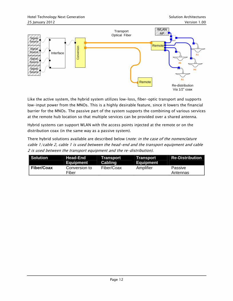
Like the active system, the hybrid system utilizes low–loss, fiber-optic transport and supports
low-input power from the MNOs. This is a highly desirable feature, since it lowers the financial
barrier for the MNOs. The passive part of the system supports the combining of various services
at the remote hub location so that multiple services can be provided over a shared antenna.
Hybrid systems can support WLAN with the access points injected at the remote or on the
distribution coax (in the same way as a passive system).
There hybrid solutions available are described below (note: in the case of the nomenclature
cable 1/cable 2, cable 1 is used between the head-end and the transport equipment and cable
2 is used between the transport equipment and the re-distribution).
Solution Head-End Equipment
Transport Cabling
Transport Equipment
Re-Distribution
Fiber/Coax Conversion to Fiber
Fiber/Coax Amplifier Passive Antennas
InterfaceA1
Transport
Optical Fiber
Re-distribution
Via 1/2” coax
A1
A1
A1
Co
nve
rsio
n Remote
Remote
WLAN
AP
Signal
Source
Signal
Source
Signal
Source
Signal
Source

Hotel Technology Next Generation Solution Architectures
25 January 2012 Version 1.00
Page 13
2.4.4 Comparison of Cellular Coverage Solution Architectures
As described above, there are many different types of architectures and solutions for cellular
coverage solutions. The following table outlines the pros and cons:
Active
Passive Hybrid
MNO Connectivity
Accepted by MNOs Accepted by MNOs; however, requires high-power signal source
Accepted by MNOs
Modularity Not modular, limited number of MNOs or MNO services. Low cost for single MNO/service
Not modular, supports all MNO and MNO services
Modular, easily expanded from single MNO/MNO service to multiple MNO/MNO services
Scalability Scalable from small to large deployments, adjustable signal power level per each antenna
Best suited for smaller deployments, but can scale with professional design and deployment
Scalable from small to large deployments
Reliability and Monitoring
Multiple failure points, pro-active monitoring for all elements of the system
Limited failure points, monitoring not available, troubleshooting requires professional support
Medium failure points, pro-active monitoring of active components, troubleshooting of passive components requires professional support
Environmental Active equipment in MDF, IDF, and ceilings with Power/HVAC requirement.
Passive equipment in MDF, IDF, and ceilings with no power/HVAC requirement.
Active equipment in MDF, IDF with power/HVAC requirement. Passive equipment in ceilings with no power/HVAC requirement.
4G Supports MIMO with single cable run
MIMO requires completely parallel system deployment
MIMO requires parallel cable infrastructure (some active electronics can be shared)
Converged Services
Typically, MNO Only Supports Public Safety and WLAN
Supports Public Safety and WLAN

Hotel Technology Next Generation Solution Architectures
25 January 2012 Version 1.00
Page 14
2.5 The Impact of 4G on Cellular Coverage Solutions
Beginning in 2011, MNOs have started to deploy 4G technologies, most notably 4G LTE.
4G LTE has several major requirements that must be taken into consideration for an existing as
well as new cellular coverage solutions. These include:
High modulation techniques that require better coverage and higher signal strength
MIMO (multiple input, multiple output) antenna configurations
New frequency bands (700 MHz & 1.7/2.1 GHz spectrum, but may be expanded to other
spectrums, including 850 MHz and 1900 MHz)
Channel bandwidth: 1.25-20 MHz
The impact to cellular coverage solutions include:
Coverage and signal strength – Traditionally, cellular coverage solutions have been deployed for
voice and antennas could be placed far apart and still achieve adequate coverage and signal
strength. With high-speed data services enabled by 4G, a denser antenna deployment is
required, which affects both number of antennas and associated transport cabling.
MIMO - MIMO (multiple input multiple output) technology is a key element of 4G LTE. MIMO
requires that RF be distributed over two independent channels. Depending on the coverage
solution, this may simply mean that two antennas be deployed at each antenna location (vs. one
for other cellular technologies, such as voice), but depending on the architecture, it may also
require duplication of hubs and remotes. In some cases, MNOs will require MIMO for 4G and in
other cases they do not. Upgrading to MIMO post installation can be expensive and MIMO
requirements should be understood from the beginning. The following diagram displays a
hybrid cellular coverage solution supporting

Hotel Technology Next Generation Solution Architectures
25 January 2012 Version 1.00
Page 15
4G MIMO technology:
New frequency bands – New spectrum was acquired by MNOs to implement high-speed data
services, specifically 700 MHz, 1.6 GHz, 1.7/2.1 GHz. When these are added to a cellular
coverage solution, the number of frequencies that are required to be supported can rise to 6 or
7 and the system must be carefully planned and designed to be able to add new bands and
avoid possible interference. In older systems, some components, such as combiners and
splitters, may be incompatible with these new bands and have to be replaced.
Channel bandwidth – currently LTE is implemented over single wideband channel however
future technology, LTE advanced, will require an increase spectrum usage through contiguous
and non-contiguous channel bonding. This may impact current cellular coverage solutions.
InterfaceMIMO CH A
Transport
Optical Fiber
MIMO CH A
MIMO CH A
MIMO CH A
Co
nve
rsio
n Remote
Signal
Source
Signal
Source
Signal
Source
Signal
Source
MIMO CH B
MIMO CH B
MIMO CH B
Remote
MIMO CH B