cellasic onix2 microfluidic system - zhejiang university
TRANSCRIPT

User Guide
CellASIC® ONIX2 Microfluidic SystemCat. No. CAX2-S0000

Made in U.S.A.
EMD Millipore Corporation Hayward, CA 94545
The M logo, Millipore, CellASIC, and Millex are registered trademarks of Merck KGaA, Darmstadt, Germany.
All trademarks of third parties are the property of their respective owners.
© 2016 EMD Millipore Corporation. Billerica, MA, U.S.A. All rights reserved.
20202092, Rev. 03/16
Notice
The information in this document is subject to change without notice and should not be construed as a commitment by EMD Millipore Corporation (“Millipore”) or an affiliate. Neither EMD Millipore Corporation nor any of its affiliates assumes responsibility for any errors that may appear in this document.
For research use only. Not for use in diagnostic procedures.
C

Contents
1 Introduction to the CellASIC® ONIX2 Microfluidic System .............................................. 11.1 Overview ..........................................................................................................................................................1
1.2 Benefits ............................................................................................................................................................1
1.3 Environmental Control .................................................................................................................................2
1.4 Applications ....................................................................................................................................................3
1.5 CellASIC® ONIX Microfluidic Plate and Cell Type Compatibility .....................................................3
1.6 Product Use Limitations ..............................................................................................................................3
2 Components Required .......................................................................................................... 43 Symbols Used in this User Guide / Symboles utilisés dans ce manuel d’utilisation ....... 54 Product Labeling .................................................................................................................. 65 Safety Precautions / Précautions de sécurité .................................................................... 66 Installation and Setup ......................................................................................................... 8
6.1 Packaging ........................................................................................................................................................8
6.2 Site Requirements .........................................................................................................................................8
6.3 CellASIC® ONIX2 Software Installation ..................................................................................................9
6.4 CellASIC® ONIX2 Microfluidic System Setup ........................................................................................9
7 CellASIC® ONIX2 Software Features ................................................................................137.1 Opening Screen ........................................................................................................................................... 13
7.2 Manual Mode Tab ...................................................................................................................................... 14
7.3 Plate Layout Tab.......................................................................................................................................... 19
7.4 Protocol Editor Tab ..................................................................................................................................... 21
7.5 Run Tab .......................................................................................................................................................... 25
7.6 Status Bar ..................................................................................................................................................... 28
7.7 Menu Items and Advanced Features .................................................................................................... 29
8 Operation ............................................................................................................................388.1 Before Your Experiment ............................................................................................................................ 38
8.2 Creating and Running a New Experiment ........................................................................................... 40
8.3 Repeating a Previous Experiment with Minimal Clicks ................................................................... 47
8.4 Using the Mini-view .................................................................................................................................. 48
8.5 Viewing and Exporting Data from a Previously Run Experiment ................................................. 50

9 Maintenance and Cleaning ...............................................................................................529.1 Running a System Self Check ................................................................................................................. 52
9.2 Cleaning the CellASIC® ONIX2 Microfluidic System ........................................................................ 53
9.3 Cleaning the Gasket................................................................................................................................... 53
9.4 Gasket/Manifold Assembly ...................................................................................................................... 53
9.5 Cleaning the Manifold and Tubing ........................................................................................................ 54
9.6 Replacing Manifold Luer Filters ............................................................................................................. 56
10 Troubleshooting ..................................................................................................................5711 Specifications .....................................................................................................................5912 Ordering Information .........................................................................................................6113 Technical Assistance ..........................................................................................................6214 Manufacturer .....................................................................................................................6215 Standard Warranty ............................................................................................................62
Contents, continued

CellASIC® ONIX2 Microfluidic System 1
1 Introduction to the CellASIC® ONIX2 Microfluidic System1.1 Overview
The CellASIC® ONIX2 Microfluidic System enables continuous live-cell imaging with media flow, temperature control, and gas environment control. A selection of proprietary microfluidic plate designs allows cells to be captured and exposed to different conditions via flow channels.
The system can be used with typical inverted microscopes and the microfluidic plates fit standard multiwell plate stage adapters. The CellASIC® ONIX2 Microfluidic System connects to the microfluidic plate via a pneumatic manifold that uses pressurized air to control flow within the plate. A vacuum seal created between the manifold and the microfluidic plate ensures that each well is independent and that flow rates and fluid switching are accurate. Flow and environment control are managed through a computer software program.
This user guide covers the setup and operation of the CellASIC® ONIX2 Microfluidic System. User guides for the CellASIC® ONIX Microfluidic Plates are available at www.millipore.com/cellasic.
Figure 1. CellASIC® ONIX2 Microfluidic System setup
1.2 Benefits ● The CellASIC® ONIX2 Microfluidic System provides a total solution for controlling the perfusion, temperature, and gas environment for time-lapse, live-cell imaging applications.
● The CellASIC® ONIX2 Software automates the entire experiment, allowing scheduled flow changes without supervision. Customized experiments can be performed by programming changes to media solutions, flow rates, and exposure times. The easy-to-use software is flexible and can generate simple solution-switching protocols or advanced flow profiles.

CellASIC® ONIX2 Microfluidic System2
● The precision laminar flow maintained by the system creates a highly stable environment for cells. The CellASIC® ONIX2 Microfluidic System requires only microliter volumes of fluid and can run for multiple days without refilling.
1.3 Environmental ControlThe CellASIC® ONIX2 Microfluidic System can provide both temperature and gas environment control. If you already have or do not require temperature control, the CellASIC® ONIX2 Manifold Basic can be used to provide a defined gas environment to the cell culture region. If temperature control is also desired, the CellASIC® ONIX2 Manifold XT is the solution. The CellASIC® ONIX2 Manifold XT takes advantage of the small size of the culture volume to efficiently, accurately, and conveniently maintain a precise cell culture environment. Temperature control is achieved using a convective heat exchange module where recirculating air gently and uniformly warms or cools the cells.
NOTE: For immersion objectives and air objectives with a working distance less than 2 mm, it is necessary to warm the objective using an objective heater (see Installation and Setup).
Gas control is achieved using highly accurate external premixed gas sources. The system purges the cell culture region at a gas consumption rate of only 5 mL/minute. Please contact your local sales representative for assistance in selecting the ONIX2 platform components that will work best with your specific microscopy setup and experiment.
Figure 2. Manifold and plate cutaway
Convective heat exchanger
Air pressure-driven flow
#1.5 thickness 170 µm thick glass
Cell culture chambers
Recirculating temperature-controlled gas mixture
ManifoldMicrofluidic plate
1.2 Benefits, continued

CellASIC® ONIX2 Microfluidic System 3
1.4 ApplicationsThe CellASIC® ONIX2 Microfluidic System and Plates are perfect for many live cell imaging applications. The following are some common applications:
● Long-term time-lapse imaging ● Kinetic responses to solution change
● Cell cycle analysis ● Apoptosis
● Protein localization ● Cell fixing and immunostaining
● Cell migration ● Mitosis
● GFP/CFP/YFP expression
1.5 CellASIC® ONIX Microfluidic Plate and Cell Type CompatibilityThe CellASIC® ONIX2 Microfluidic System is compatible with all CellASIC® ONIX Microfluidic Plates. Each unique plate design provides compatibility with a range of cell sizes and types as follows:
Y04 Series Microfluidic Plates are compatible with non-adherent cells that are 3.5–7 µm in diameter. Examples: S. cerevisiae, S. pombe
B04 Microfluidic Plates are compatible with non-adherent cells that are 0.7–4.5 µm in diameter. Examples: E. coli, B. subtilis, cyanobacteria
M04 Series Microfluidic Plates are compatible with any adherent or non-adherent mammalian cell line capable of culture on glass. Examples: MCF-7, HeLa, NIH3T3, PC3, primary cells, stem cells
C04 Microfluidic Plates are compatible with non-adherent flagellates. Example: Chlamydomonas
For the most up-to-date list of our current plate types, please visit www.millipore.com/cellasic.
Please contact Technical Service for questions about cell types or coatings.
1.6 Product Use LimitationsThe CellASIC® ONIX2 Microfluidic System is intended for research use only. It is not for use in diagnostic procedures.
All due care and attention should be exercised in the handling of the CellASIC® ONIX2 Microfluidic System and CellASIC® ONIX Microfluidic plates. Instructions provided in this manual should be followed when using CellASIC® ONIX2 System.
If the equipment is used in a manner not specified by the manufacturer, protection provided by the equipment may be impaired and the warranty may be voided.

CellASIC® ONIX2 Microfluidic System4
2 Components RequiredThe following components are required for a functional CellASIC® ONIX2 System. Refer to Ordering Information for additional manifolds, accessories, and other components.
Component Catalogue Number
CellASIC® ONIX2 Microfluidic System(includes ONIX2 Filter Multiconnector, Software USB Drive, Replacement Filter Pack, Accessory Fittings, Self Check Plate, Cleaning Plate)
CAX2-S0000
CellASIC® ONIX2 Manifold XT (Temperature Controlled)
ORCellASIC® ONIX2 Manifold Basic (No Temperature Control)
CAX2-MXT20
CAX2-MBC20
CellASIC® ONIX Microfluidic Plates Refer to Ordering Information

CellASIC® ONIX2 Microfluidic System 5
3 Symbols Used in this User Guide / Symboles utilisés dans ce manuel d’utilisation
The following symbols are used throughout this user guide and/or on product labels, and the user shall abide by indicated requirements:
Les symboles suivants sont utilisés tout au long de ce manuel d’utilisation et/ou sur les étiquettes des produits ; l’utilisateur devra respecter les exigences indiquées :
Symbol / Symbole Definition Définition
YCaution, consult accompanying documents.
Attention, consultez les documents joints.
CCE conformity marking. Reference Declaration of Conformity for specific directives.
Marquage de la conformité CE. Déclaration de conformité à certaines directives pour référence.
hCatalogue number Référence
NDate of manufacture Date de fabrication
MManufacturer Fabricant
fSerial number Numéro de série
iConsult instructions for use. Consultez le mode d’emploi.
Federal Communications Commission (FCC) conformity marking
Marquage de la conformité avec la Commission fédérale des communications américaine (FCC pour Federal Communications Commission)
Canadian Standards Association® (CSA) conformity marking
Marquage de la conformité avec l’Association canadienne de normalisation (CSA pour Canadian Standards Association®)
Do not discard with common solid waste at end of life. Segregate with other waste electrical and electronic equipment (WEEE) and send to an appropriate facility for recycling. For information on recycling electrical and electronic products in the European Union, please visit www.millipore.com/weee.
Ne pas jeter avec les déchets solides communs en fin de vie. Mettre à part avec les autres déchets d’équipements électriques et électroniques (DEEE) et envoyer à une entreprise habilitée pour recyclage. Pour une information sur le recyclage des produits électriques et électroniques dans l’Union européenne, veuillez consulter la page www.millipore.com/weee sur Internet.

CellASIC® ONIX2 Microfluidic System6
4 Product Labeling
Figure 3. Product label appears on back of the system
5 Safety Precautions / Précautions de sécuritéReview and understand the safety precautions below before installing and operating the CellASIC® ONIX2 Microfluidic System.
Lire et comprendre les précautions de sécurité ci-dessous avant d’installer et de faire fonctionner le Système de microfluidique CellASIC® ONIX2.
Y WARNING Y ATTENTIONTo avoid danger of electric shock, do not install the system in an area with a high humidity level. Refer to Site Requirements in section 6.
Pour éviter le risque de choc électrique, ne pas installer le système dans une zone où le taux d’humidité est élevé. Se reporter au paragraphe “Site Requirements” (Exigences relatives au lieu d’installation) de la Section 6.
Do not touch the cables or power plugs with wet hands.
Ne pas toucher les câbles ou les prises électriques avec des mains mouillées.
To avoid potential shock hazard, use the correct plug configuration and make sure that the power cable is plugged securely into a properly grounded AC power outlet. Make sure that the connection between the cable and the system is secure.
Pour éviter le risque potentiel de choc, utiliser la bonne configuration de prise et s’assurer que le câble électrique est solidement branché dans une prise de courant correctement reliée à la terre. S’assurer que la connexion entre le câble et le système est sécurisée.
Always ensure that the power supply input voltage matches the voltage available in your location.
Toujours s’assurer que la tension du courant d’alimentation du système correspond bien à la tension disponible sur place.
Use only the power cables supplied by EMD Millipore Corporation for use with the CellASIC® ONIX2 Microfluidic System. Use of other power cables may damage the system.
Utiliser uniquement les câbles électriques fournis par EMD Millipore Corporation pour une utilisation avec le Système de microfluidique CellASIC® ONIX2. L’utilisation d’autres câbles électriques pourrait endommager le système.

CellASIC® ONIX2 Microfluidic System 7
Y WARNING Y ATTENTIONMinimize power draw from other instruments on the same power circuit.
Minimiser la consommation de courant par d’autres instruments branchés sur le même circuit.
Do not use with flammable or explosive liquids. Ne pas utiliser avec des liquides inflammables ou explosifs.
Before cleaning and moving the system, always turn off power and unplug power supply.
Avant de nettoyer ou de déplacer le système, toujours l’éteindre et le débrancher.
When working with biological material, always wear a suitable lab coat, disposable gloves, and eye protection. Proper lab safety should always be followed when using the system.
Lorsque vous travaillez avec des matières biologiques, toujours porter une blouse de laboratoire, des gants à usage unique et une protection oculaire adéquats. Il convient de toujours suivre les mesures de sécurité au laboratoire appropriées lors de l’utilisation du système.
For all experiments, perform biosafety risk assessment, mitigation, decontamination, and waste disposal procedures in accordance with established national and institutional guidelines.
Pour toute expérience, effectuer les procédures d’évaluation et de réduction des risques de biosécurité, de décontamination et d’élimination des déchets conformément aux directives nationales et institutionnelles en place.
FCC statement: This equipment has been tested and found to comply with the limits for a Class A digital device, pursuant to part 15 of the FCC Rules. These limits are designed to provide reasonable protection against harmful interference when the equipment is operated in a commercial environment. This equipment generates, uses, and can radiate radio frequency energy and, if not installed and used in accordance with the instruction manual, may cause harmful interference to radio communication. Operation of the equipment in a residential area is likely to cause harmful interference, in which case the user will be required to correct the interference at his own expense.
Déclaration FCC : Cet équipement a été testé et s’est avéré conforme aux limites pour un dispositif numérique de la Classe A, conformément à la Section 15 du Règlement FCC. Ces limites sont conçues pour assurer une protection raisonnable contre les interférences préjudiciables lorsque l’équipement est exploité dans un environnement commercial. Cet équipement génère, utilise et peut émettre de l’énergie à radiofréquences et, s’il n’est pas installé et utilisé conformément au manuel d’instruction, peut provoquer des interférences préjudiciables pour les communications radio. L’utilisation de l’équipement dans une zone résidentielle est de nature à provoquer des interférences préjudiciables, auxquelles l’utilisateur devra remédier à ses frais.
CSA® statement: This Class A digital apparatus complies with Canadian ICES-003.
Déclaration CSA® : Cet appareil numérique de Classe A est conforme avec la norme canadienne ICES-003.
5 Safety Precautions / Précautions de sécurité, continued

CellASIC® ONIX2 Microfluidic System8
6 Installation and Setup6.1 Packaging
Inspect the packaging for damage upon receipt. If there are any signs of damage, contact the responsible shipping company.
Y WARNING Y ATTENTIONDo not put system components showing signs of damage into operation as this may result in severe personal injury and/or property damage.
Ne pas mettre en marche des composants du système présentant des signes de dommages, car cela pourrait provoquer des blessures corporelles graves et/ou des dommages matériels.
NOTE: Systems will not be accepted for repair if not in original packaging. EMD Millipore Corporation will provide shipping boxes for a charge if original packaging has been discarded.
6.2 Site RequirementsThe CellASIC® ONIX2 Microfluidic System is designed for indoor laboratory use. The user must provide an installation site that meets the following requirements.
Space requirement Stable and horizontal base able to bear the weight of microfluidic system components and user-provided components.
Width Length Height Weight330 mm (13 in.) 306 mm (12 in.) 108 mm (4.25 in.) 6.7 kg (14.75 lb)
DOC 20199741 REV 1
330 mm
108
mm
306 mm
Environment Operating temperature range: 20–30 °CKeep away from bright sunlightHumidity < 80%, noncondensing
Power supply Voltage range: 100–240 VAC, 40 WFrequency range: 50/60 HzConnect the CellASIC® ONIX2 Microfluidic System only to a grounded power outlet.Take precautions to ensure uninterrupted power supply if there is the potential for power supply issues (e.g., brownouts, power surges, frequent thunderstorms, etc.).

CellASIC® ONIX2 Microfluidic System 9
6.3 CellASIC® ONIX2 Software InstallationIn order to run this software, your computer must meet the requirements outlined below:
Windows® 7 or Windows® 10 operating system (32 or 64 bit)4 GB RAM or higher1920 × 1080 resolution monitor or higher200 MB or higher hard drive spaceKeyboard, mouse, USB port
NOTE: Two USB ports required if using Temperature Calibration Plate (CAX2-ACT20)
To install the CellASIC® ONIX2 Software onto the computer, insert the provided USB drive into the USB port on the computer, or download the most recent version of the software from www.millipore.com/cellasic. If downloaded from the website, first “extract” the zipped package if it is compressed. Run the ONIX2 installer executable (e.g., ONIX2 v1.0 Installer.exe). An installation wizard guides you through the installation of the software. Simply follow the prompts. Administrator rights are required for installation.
6.4 CellASIC® ONIX2 Microfluidic System SetupRemove all components from shipping boxes and lay out on work surface.
1. Place the CellASIC® ONIX2 Microfluidic System within 1–2 meters of an inverted microscope. For best results, locate the system on a flat surface isolated from the microscope and route the manifold tubing so that it does not hinder stage movement.
2. Connect the power cord from a grounded electrical outlet to the system (D in Figure 4). The internal power supply accepts any voltage source between 100 and 240 VAC. Connect the USB cable from the computer to the USB port (C in Figure 4) on the back panel of the system.
Y WARNING Y ATTENTIONTo avoid personal injuries and/or property damage caused by electrical power, connect the system and computer to a grounded power outlet. Make sure that this power outlet complies with IEC (International Electrotechnical Commission) regulations.
Pour éviter les blessures corporelles et/ou les dommages matériels causés par le courant électrique, brancher le système et l’ordinateur à une prise de terre. S’assurer que cette prise est conforme à la réglementation IEC (International Electrotechnical Commission).
CellASIC® ONIX2 Microfluidic System10
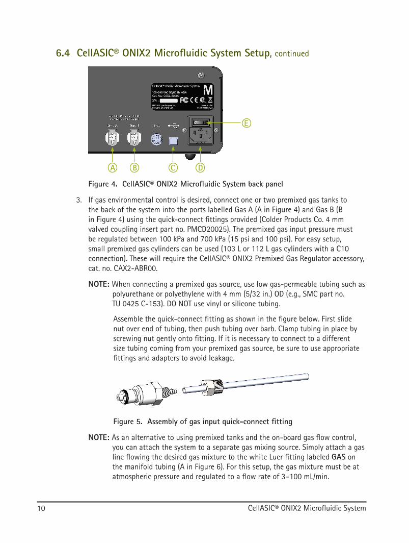
Figure 4. CellASIC® ONIX2 Microfluidic System back panel
A DB C
E
3. If gas environmental control is desired, connect one or two premixed gas tanks to the back of the system into the ports labelled Gas A (A in Figure 4) and Gas B (B in Figure 4) using the quick-connect fittings provided (Colder Products Co. 4 mm valved coupling insert part no. PMCD20025). The premixed gas input pressure must be regulated between 100 kPa and 700 kPa (15 psi and 100 psi). For easy setup, small premixed gas cylinders can be used (103 L or 112 L gas cylinders with a C10 connection). These will require the CellASIC® ONIX2 Premixed Gas Regulator accessory, cat. no. CAX2-ABR00.
NOTE: When connecting a premixed gas source, use low gas-permeable tubing such as polyurethane or polyethylene with 4 mm (5/32 in.) OD (e.g., SMC part no. TU 0425 C-153). DO NOT use vinyl or silicone tubing.
Assemble the quick-connect fitting as shown in the figure below. First slide nut over end of tubing, then push tubing over barb. Clamp tubing in place by screwing nut gently onto fitting. If it is necessary to connect to a different size tubing coming from your premixed gas source, be sure to use appropriate fittings and adapters to avoid leakage.
Figure 5. Assembly of gas input quick-connect fitting
NOTE: As an alternative to using premixed tanks and the on-board gas flow control, you can attach the system to a separate gas mixing source. Simply attach a gas line flowing the desired gas mixture to the white Luer fitting labeled GAS on the manifold tubing (A in Figure 6). For this setup, the gas mixture must be at atmospheric pressure and regulated to a flow rate of 3–100 mL/min.
6.4 CellASIC® ONIX2 Microfluidic System Setup, continued

CellASIC® ONIX2 Microfluidic System 11
4. Securely attach the vacuum Luer fitting (black), eight pressure Luer filters (translucent), and gas Luer fitting (white) from the manifold to the Luer fittings on the CellASIC® ONIX2 Filter Multiconnector, cat. no. CAX2-AMC00 (Figure 6). The Filter Multiconnector can be plugged into the front panel of the system as shown in the figure below. Magnets and spacing prevent the connector from being plugged in incorrectly. To disconnect, pull on the tabs on both ends (B).
Figure 6. Connecting the Filter Multiconnector
A
B
B
Important: Match each fitting to the corresponding line in order. The black fitting must be matched to black line labelled VAC. Before starting each experiment, make sure all eight Luer filters are securely attached to the fittings and that the Filter Multiconnector is securely pushed all the way into the front panel until it seats. At the same time, check to see that there is no liquid contamination in the manifold tubing and/or filters. If contamination is observed, clean tubing and manifold by running the cleaning sequence and replace Luer filter(s) according to Maintenance and Cleaning.
Figure 7. Connecting the manifold plug
Pull on knurled sheath to disconnect
5. If the temperature controlled CellASIC® ONIX2 Manifold XT is being used, you must also connect the 4-conductor plug from the manifold. Align the red mark on the top of the plug to the dot on the front panel and push the plug into the socket labeled Manifold (Figure 7) on the front of the system. The plug can be removed by pulling on the sheath; be sure to grab only the knurled sheath when pulling to disconnect.
6.4 CellASIC® ONIX2 Microfluidic System Setup, continued

CellASIC® ONIX2 Microfluidic System12
6. Turn on the system power using the switch on the back panel above the power cord entry (E in Figure 4). The green Ready indicator (G in Figure 8) will light up when the unit is ready for operation.
7. Run the ONIX2 Software (Windows Start Menu→All Programs→EMD Millipore→ONIX2→ONIX2). The status bar at the bottom of the window should say Ready.
NOTE: If a connection does not happen automatically when using the system for the first time, go to the Tools menu and select Settings to manually establish a connection to the ONIX2 Microfluidic System. Refer to section 7.7.2, Tools Menu for instructions.
8. You may perform a System Self Check to confirm ideal operation of the system. Refer to Maintenance and Cleaning for instructions on running a System Self Check.
Figure 8. CellASIC® ONIX2 Microfluidic System front panel
Indicator light MeaningReady (G) Lit when system is ready, blinking if
system is not yet ready or there is a warning
Sealed (H) Lit when plate is sealed, blinking while attempting to seal
Error (I) Blinking if there is an errorJF G H I
6.4 CellASIC® ONIX2 Microfluidic System Setup, continued

CellASIC® ONIX2 Microfluidic System 13
7 CellASIC® ONIX2 Software Features7.1 Opening Screen
Figure 9. Opening screen options
C
B
A
7.2.2 Create an Experiment
New Experiment (A) - Select to start a new experiment file. You will then need to select the plate type before a new experiment file is created.
New Experiment Based on Previous (B) - Select to start new experiment based on an existing one. All data from the previous experiment will be copied except for the experiment’s run data.
7.2.3 Open an Experiment
Open Previous Experiment (C) - Select to open an existing experiment, either a previously completed experiment with run data, or an experiment that has been saved but not yet run.

CellASIC® ONIX2 Microfluidic System14
7.2 Manual Mode TabThe Manual Mode tab allows interactive operation of the ONIX2 System.
Figure 10. Manual Mode tab
BE
FD
CA G
7.2.1 Plate ViewStable and accurate flow control is achieved using air pressure above the liquid in each well. Multiple wells on a plate are grouped together and addressed by a single pneumatic line via the manifold. Each set of wells is called a “well group” and can be addressed by one of two pressures, pressure X or pressure Y. The plate view section allows the user to manually turn on/off well groups, select X/Y pressure for each well group, and set X and Y pressure values.
Each colored bar is a Well Group (A). Click on one to manually turn it on or off. When on, pressure is applied to the set of wells; when off, the wells are vented to atmospheric pressure. Sometimes, you will notice multiple well groups are “tied” together, i.e., they are not allowed to be activated independently.
Click Perfusion Off (B) to turn off all open well groups immediately.
Unlock the Access to All Well Groups lock (C) to enable the setting of any well group rather than just the standard perfusion well groups.
NOTE: Well groups other than the standard perfusion well groups sometimes have low fluidic resistance and therefore a high liquid flow rate. Be careful when activating these well groups that you don’t run out of fluid in the wells.

CellASIC® ONIX2 Microfluidic System 15
7.2 Manual Mode Tab, continuedIn Pressure Control, entering a value (D) sets the pressure level in kilopascals. The control prevents setting a pressure outside of limits which are based on initial plate selection.
Clicking kPa will open up a conversion tool allowing conversion of psi into kPa (Figure 11).
Figure 11. Psi to kPa converter tool
The Dual Pressure Mode button (E in Figure 10) activates the secondary pressure for more advanced control capabilities. In this mode, pressure X and pressure Y can be selectively addressed to any of the eight well group outputs. By default, all well groups are addressed by pressure X as indicated by the color of the circle below each well group button. Click on the circles to change to pressure Y or back to pressure X (Figure 12).
Figure 12. Dual pressure mode

CellASIC® ONIX2 Microfluidic System16
The Unit View window (F in Figure 10) shows a graphic of the microfluidic culture chamber and the location and direction of the flow from the different inputs. The colors of each input to the culture chamber correspond to the associated well group.
Click on the Mini-view icon in the top-right of the plate view section (G in Figure 10) to open the floating manual mini-view window as described below.
7.2.2 Environment ControlAllows user to manually set environment control parameters
Environment Control paneTemperature control can be turned On/Off and the target setpoint adjusted.
Gas Flow can be turned On/Off, gas A or gas B selected, and Slow or Fast flow rate selected. Select slow flow rate if running an experiment in the same gas environment. Select the fast flow rate when switching to a different gas environment, so that the new gas environment is achieved swiftly.
When gas environment control is turned On, consumption of premixed gas mixture will be approximately 5 mL/min at slow flow or 50 mL/min at fast flow (e.g., a typical nominal 330 CF tank of premixed gas will last for approximately 6 years at continuous slow flow or 6 months at fast flow.)
7.2.3 Plate Setup SequencesShort automated sequences can be run using this feature. When an experiment file is first created, these sequences are populated with defaults according to the plate type. Using the default setting specific to each plate is recommended, however, optimization may still be required depending on the cell type and/or concentration. Edited sequences are saved as part of the experiment file when the experiment file is saved and can be repeated by “creating a new experiment based on previous” and selecting the previously saved experiment. For some plate types, cell loading can be achieved without using the software and ONIX2 Microfluidic System. For example, the M04S-03 ONIX microfluidic plates can be gravity-loaded by pipette.
7.2 Manual Mode Tab, continued
CellASIC® ONIX2 Microfluidic System 17
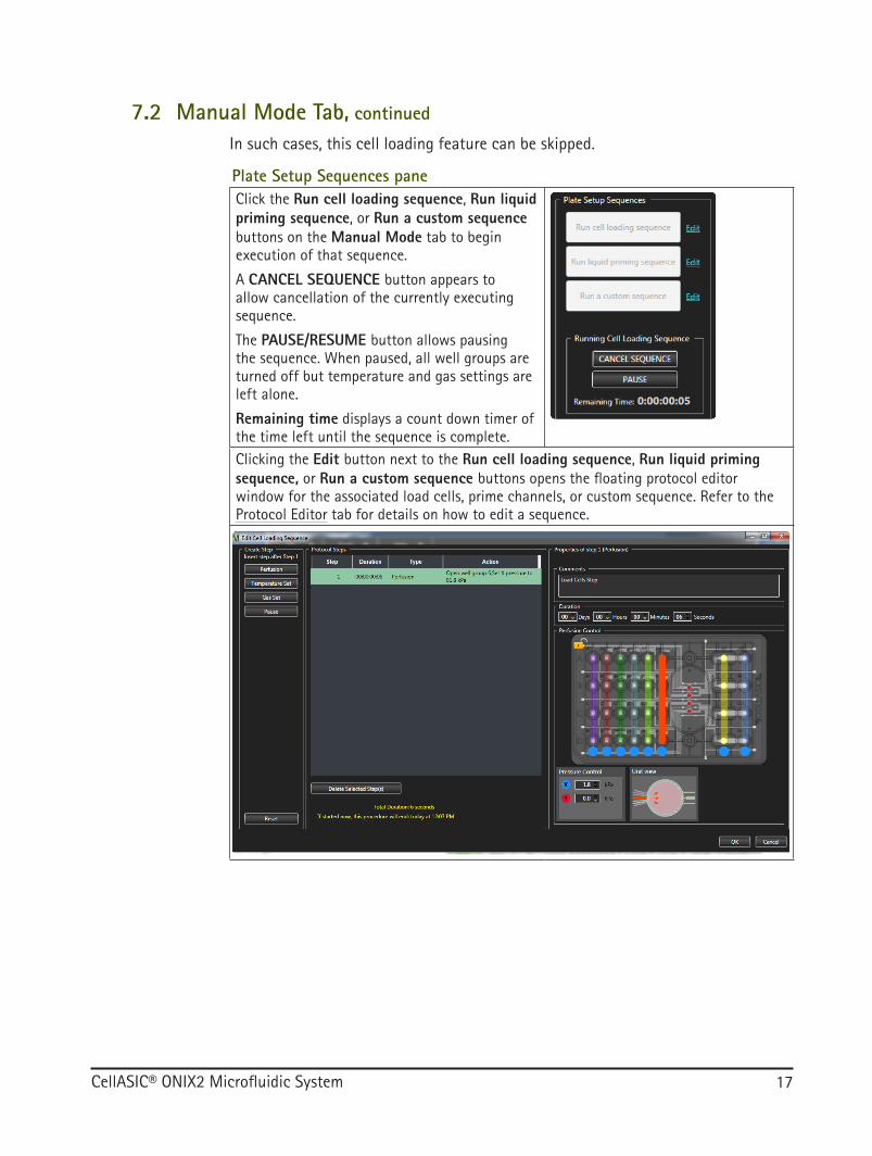
In such cases, this cell loading feature can be skipped.
Plate Setup Sequences paneClick the Run cell loading sequence, Run liquid priming sequence, or Run a custom sequence buttons on the Manual Mode tab to begin execution of that sequence.
A CANCEL SEQUENCE button appears to allow cancellation of the currently executing sequence.
The PAUSE/RESUME button allows pausing the sequence. When paused, all well groups are turned off but temperature and gas settings are left alone.
Remaining time displays a count down timer of the time left until the sequence is complete.Clicking the Edit button next to the Run cell loading sequence, Run liquid priming sequence, or Run a custom sequence buttons opens the floating protocol editor window for the associated load cells, prime channels, or custom sequence. Refer to the Protocol Editor tab for details on how to edit a sequence.
7.2 Manual Mode Tab, continued

CellASIC® ONIX2 Microfluidic System18
7.2.4 Plate Mini-viewThe Plate View mini-view (G in Figure 10) is a small control window which can float on top of other windows and is intended to be used in parallel with your microscopy software.
Plate Mini-viewThe Always on Top button sets the window to float on top of all other application windows in case your microscopy software takes up the full screen.All other controls are the same as in the Manual Mode tab of the main application.
7.2 Manual Mode Tab, continued

CellASIC® ONIX2 Microfluidic System 19
7.3 Plate Layout TabThis tab gives you the option to enter experiment information and notes. The information is recorded in the experiment file and included in generated reports. When a new experiment is created based on a previous experiment, all of the information entered on this tab (except the plate barcode number) is copied into the new experiment file.
Figure 13. Plate Layout tab
A
C
D
B
You may enter information into the fields provided. Tab and Shift*Tab move horizontally through the fields, while Enter and Shift*Enter move vertically.
Plate Barcode (A) Record the barcode number of your plate hereWell text fields for A1 to D8 (C) Record the media and cell solutions loaded into each
well hereText Description (B) Describe your experiment in this fieldClear All Values (D) Click button to clear all text fields on this tab
CellASIC® ONIX2 Microfluidic System20
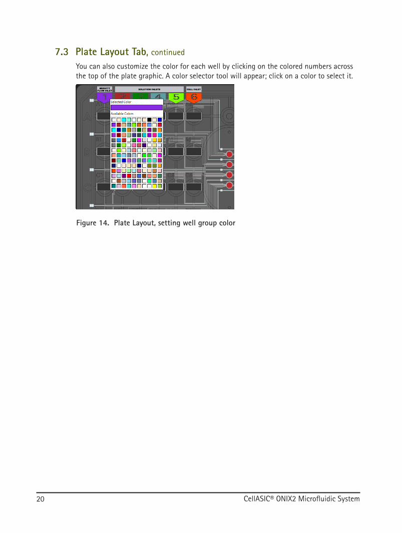
You can also customize the color for each well by clicking on the colored numbers across the top of the plate graphic. A color selector tool will appear; click on a color to select it.
Figure 14. Plate Layout, setting well group color
7.3 Plate Layout Tab, continued

CellASIC® ONIX2 Microfluidic System 21
7.4 Protocol Editor TabThe Protocol Editor allows the creation and editing of an experiment protocol. A protocol is comprised of a sequence of environment control and/or perfusion steps. Steps can be added and altered as desired. When the experiment protocol is ready, it can be executed using the Run tab. To modify the parameters of a step, select the step in the protocol and use the step editor pane on the right side (E).
Figure 15. Protocol Editor tab
ABCD
E
Protocol Editor provides options to:
● Insert a new step anywhere in the sequence
● Modify parameters of any step
● Delete a set of steps
● Copy a set of steps and insert the copied steps at a specific point of the sequence
● Create loops of steps
● Insert plate-setup sequences
After an experiment run has started, the protocol can only be viewed and no longer modified. To modify the protocol again, you will need to create a new experiment file based on the currently open one.

CellASIC® ONIX2 Microfluidic System22
7.4.1 Step Editor PaneEach step within a protocol can be edited using the Step Editor pane, which is displayed on the right when a single step is selected.
Step Step Editor Pane DescriptionPerfusion Step (A in Figure 15)
A perfusion step sets the pressure and well group(s) states for a specified duration.See description in Manual Mode Tab for more details on how to control perfusion.
Temperature Set (B in Figure 15)
A Temperature Set step turns On/Off the temperature control and sets the target temperature.The state of temperature control and the target setpoint will remain until the next Temperature Set step, or when the protocol completes.
7.4 Protocol Editor Tab, continued

CellASIC® ONIX2 Microfluidic System 23
Step Step Editor Pane DescriptionGas Set (C in Figure 15)
A Gas Set step sets the gas environment conditions: flow can be On/Off, A/B, and Slow/Fast.The state of gas flow will remain until the next Gas Set step, or when the protocol completes.
Pause (D in Figure 15)
When the procedure executor encounters a Pause step, it halts execution and notifies the user, giving them the option to resume or abort the run. If Duration is set to zero, the pause will continue indefinitely and can be manually resumed at any time. Otherwise, the protocol will automatically resume after the specified time completes.
If the Keep well groups open during pause box is checked, the previously existing perfusion state will continue during the pause. If the box is not checked, flow is stopped (i.e., well groups are closed) during the pause. In this case, the user is free to unseal and reseal the plate while in the paused state. Temperature and gas flow continue in either case.
7.4.2 Insert a New StepClick on Perfusion, Gas Set, Temperature Set, or Pause buttons on the left (A, B, C, or D in Figure 15) to create a new step of that type. The step will be inserted after the most recently selected step.
7.4.3 Delete a Set of StepsTo delete one or more steps, click on the step or use the shift and control keys while clicking to select multiple steps. Click Delete Selected Step(s) or press the delete key to delete the selected steps.
7.4 Protocol Editor Tab, continued

CellASIC® ONIX2 Microfluidic System24
7.4.4 Copy/Cut and Paste a Set of StepsTo copy one or more steps, click on the step or use the shift and control keys to click on multiple steps. Then right click on one of the selected steps and click Copy. To paste, select one step, right click on the step, and then click Paste. The copied steps will be inserted immediately following the selected step. The keyboard shortcuts Ctrl-c for copy, Ctrl-x for cut, and Ctrl-v for paste can also be used.
7.4.5 Group and Repeat StepsThe user can select a set of one or more consecutive steps to group them, in order to repeat that set:
Select one or more steps by clicking on the step or using the shift and control keys to select multiple steps.
Right-click on selected steps and select Group and Repeat.
The selected steps become a “group step” which can be repeated. User can select a repeat count.
NOTE: To ungroup, right-click on a group and select Ungroup to release the grouping.
7.4.6 Insert SequenceIn order to insert one of the already defined Cell Load, Prime Channels, or Custom sequences, right click on a step and select Insert sequence before and choose the desired sequence. This will copy the entire set of steps from the chosen sequence and insert them just prior to the selected step in the protocol.
7.4 Protocol Editor Tab, continued

CellASIC® ONIX2 Microfluidic System 25
7.5 Run TabThe Run tab is used to start and monitor the execution of a protocol.
Figure 16. Run tab during a protocol run
A
CD E
F
J
K LMG H
I
B
N
7.5.1 Run dataThis area (A) displays run data if the experiment has been run or is currently being run.
Display Settings (B) Click to show or hide columns.Export (C) Click to export the experiment data in tab-separated
value format (same as File→Export Run Data).
7.5.2 Plate ViewThe plate view (D) shows the current state of the system as the protocol is being executed. When a protocol is not running, the plate view can be used as a control, similar to the Manual Mode tab; when a protocol is running, the controls are disabled.
Mini-view (E) Click to open the floating manual control (also accessible from Manual Mode tab).
CellASIC® ONIX2 Microfluidic System26
7.5.3 Dynamic Timeline
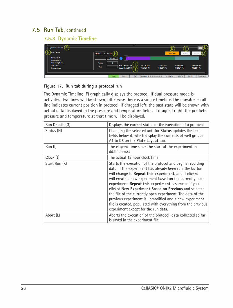
Figure 17. Run tab during a protocol run
F
J
K LMG H
I
N
The Dynamic Timeline (F) graphically displays the protocol. If dual pressure mode is activated, two lines will be shown; otherwise there is a single timeline. The movable scroll line indicates current position in protocol. If dragged left, the past state will be shown with actual data displayed in the pressure and temperature fields. If dragged right, the predicted pressure and temperature at that time will be displayed.
Run Details (G) Displays the current status of the execution of a protocolStatus (H) Changing the selected unit for Status updates the text
fields below it, which display the contents of well groups A1 to D8 on the Plate Layout tab.
Run (I) The elapsed time since the start of the experiment in dd:hh:mm:ss
Clock (J) The actual 12 hour clock timeStart Run (K) Starts the execution of the protocol and begins recording
data. If the experiment has already been run, the button will change to Repeat this experiment, and if clicked will create a new experiment based on the currently open experiment. Repeat this experiment is same as if you clicked New Experiment Based on Previous and selected the file of the currently open experiment. The data of the previous experiment is unmodified and a new experiment file is created, populated with everything from the previous experiment except for the run data.
Abort (L) Aborts the execution of the protocol; data collected so far is saved in the experiment file
7.5 Run Tab, continued

CellASIC® ONIX2 Microfluidic System 27
Pause (M) Temporarily pauses execution of the protocol. While paused, the button changes to Resume and experiment can be resumed when the user desires. Pause turns off well groups but keeps temperature and pressure settings. When the user resumes the experiment, previous well groups and pressure configuration are restored. The Pause button also changes to Resume whenever the protocol hits a programmed undetermined pause. However, determined pauses (e.g., a 5 minute programmed pause) cannot be manually resumed before the end of their scheduled duration.
Mini-view (N) Opens the floating mini-view dynamic timeline
7.5.4 Dynamic Timeline Mini-view
O
Figure 18. Dynamic Timeline mini-view
The mini-view is intended to be a small interface companion to your microscopy software. All other controls are the same as in the Dynamic Timeline described above.
Always on Top (O) Sets the window to float on top of all other application windows
7.5 Run Tab, continued

CellASIC® ONIX2 Microfluidic System28
7.6 Status BarThe status bar is displayed at the bottom of the main window and manual mini-view. It displays current system status at all times.
Figure 19. Status bar and error/warning tray
I
A C D E F G HB
Display Field Status DescriptionSystem status (A) Options for status:
DisconnectedNot readyReadyRunningPaused
Sealed status (B) Not sealedSealed
Error status (C) OKWARNING (flashes orange)ERROR (flashes red)If there is an error or warning, click on the ERROR/WARNING button in the status bar to bring up the error/warning tray (I) for details (only in the main application).
Output status (D) Outputs: well group output state in order from 1 to 8.Shows an empty circle if well group is off, or a filled circle with color according to X or Y pressure color.
Pressure X status (E) X: pressure in kPaPressure Y status (F) Y: pressure in kPaGas flow status (G) Gas: Off or flow source and flow rate
Options for flow source:A (or text from settings if it exists)B (or text from settings if it exists)
Options for flow rate:SlowFast
Temperature status (H) Temp: temperature of manifoldIf no manifold connected "--"

CellASIC® ONIX2 Microfluidic System 29
7.7 Menu Items and Advanced Features
7.7.1 File Menu
Figure 20. File menu
A
CDEFGH
B
I
New Experiment (A) Select to start a new, previously undocumented experiment. A plate type selection window opens and when a plate type is chosen, a new experiment file is created.
New Experiment Based on Previous (B)
Select to start a new experiment based on an existing one. An experiment file browser opens and when the user selects an experiment, a new experiment is created and pre-populated with the plate layout and protocol from the selected experiment (but no run data).
Open Previous Experiment (C)
Select to open an existing experiment, either a previously completed run (protocol and data), or an experiment that has been saved but not yet run.
Save Experiment (D) Saves your experiment filePrint Experiment Report (E) Prints the Experiment Report which can either be saved as a PDF or
sent to a printer. If desired, there is an option to automatically save a PDF Experiment Report when the experiment file is saved. This option is accessible in Tools→Settings→Application.
Export Run Data (F) Exports the current run data in tab-separated text file format (.tsv)Close Experiment (G) Closes currently open experiment and returns to the opening screenRecent Experiments (H) Shows the 10 most recently opened experiment filesExit (I) Exits the application

CellASIC® ONIX2 Microfluidic System30
7.7.2 Tools Menu
Figure 21. Tools menu
A
Settings (A) - System TabEstablishes a connection to the ONIX2 Microfluidic System. A connection to the most recently successful port is automatically attempted when the software is opened. If a connection is not automatically established, search for the serial number of your system in the Communication Port selector (the system must be connected and powered on), then click Connect.
Settings (A) - Application TabYou may choose well group and pressure default colors on this Settings tab.
In the Pneumatic Configuration section you may also set a text description of the gas mix-tures connected to gas inputs A and B on the rear of the system. These descriptions will be visible in the application when gas flow is used and are also saved to the experiment data file when the experiment is run.
Checking the box in the Auto-Save Report section will automatically save a PDF file of the experiment report every time the experiment is saved. The PDF will have the same file name as the experiment file and will be overwritten when resaved.
7.7 Menu Items and Advanced Features, continued

CellASIC® ONIX2 Microfluidic System 31
Settings (A) - Notifications TabEmail alerts can be sent through the CellASIC® ONIX2 Software to specified recipients when a protocol is completed or disrupted. In order to do this, an outgoing email address and mail server must be specified in notifications tab of the settings dialogue. This outgoing email address/server will be saved and act as the sender email address in all communications from the CellASIC® ONIX2 Software-specified recipients until another email address/server is entered. If the ONIX2 platform is shared among different users, it is recommended that a shared sender’s email address be set up to avoid confusion. Then enter recipient email addresses that you’d like to receive the email. Click the Send Test Email button to test email functionality. The ONIX2 software will indicate whether the email was sent successfully. If successful, a test email using the sender’s email address will appear in the recipient’s inbox with the subject “CellASIC® ONIX2 Email Test”. After confirmation of receiving the email, click OK to complete Email Alert setup.
NOTE: Please check your local network connectivity and firewall settings to allow Email Alert capability on the CellASIC® ONIX2 Software.
7.7 Menu Items and Advanced Features, continued

CellASIC® ONIX2 Microfluidic System32
Settings (A) - Notification Tab, continued
Fill out all fields in the Email Alert Settings pop-up window according to email service provider. Below are example settings for some of the most commonly used email services. If in doubt, please check with your email service provider.
NOTE: Some service providers may require additional account configuration to enable mail access. For example Gmail™ email requires the user to go to account settings, and under "Sign-in & security" turn "Allow less secure apps" on.
Email Service Provider Server Settings ExamplesGmail™ Outgoing Mail Server (SMTP): smtp.gmail.com
Port: 587Sender’s Email Address: Gmail™ address of your or your group’s choosing to send the alertsUsername: Full Gmail.com email address (same as above)Password: Gmail™ password for this account
Outlook® Outgoing Mail Server (SMTP): smtp.live.comPort: 587Sender’s Email Address: Outlook® email address of your or your group’s choosing to send the alertsUsername: Full Outlook.com email address (same as above)Password: Outlook.com password for this account
Comcast® Outgoing Mail Server (SMTP): smtp.comcast.netPort: 587Sender’s Email Address: Comcast® email address of your or your group’s choosing to send the alertsUsername: Full Comcast® email address (same as above)Password: Comcast® password for this email account
Yahoo!® Outgoing Mail Server (SMTP): smtp.mail.yahoo.comPort: 587Sender’s Email Address: Yahoo!® email address of your or your group’s choosing to send the alertsUsername: Full Yahoo!® Mail email address (same as above)Password: Yahoo!® Mail password for this email account
AT&T® Outgoing Mail Server (SMTP): smtp.mail.att.netPort: 587Sender’s Email Address: AT&T® email address of your or your group’s choosing to send the alertsUsername: Full AT&T® email address (same as above)Password: AT&T® password for this email account
7.7 Menu Items and Advanced Features, continued

CellASIC® ONIX2 Microfluidic System 33
Settings (A) - Automation TabThe check boxes on this tab enable external control of the CellASIC® ONIX2 Software, for more powerful integration with your microscopy software. For details on the features of the application programming interface (API), please contact Technical Service.
System and Manifold Self Check (B)To ensure that the system is installed and running properly, run the System and Manifold Self Check. For details refer to Maintenance and Cleaning section.
B
ManifoId Cleaning (C)Refer to Maintenance and Cleaning section.
C
Temperature Calibration (D)A Temperature Calibration Plate is available as an optional accessory. It consists of a very accurate temperature probe embedded inside a microfluidic plate precisely where the cells would be cultured. By following the steps below, the Temperature Calibration Plate can be used to improve the accuracy of the sample chamber temperature from ± 1 °C (without the Temperature Calibration Plate) to as high as ± 0.2 °C (with the Temperature Calibration Plate). We recommend using a Temperature Calibration Plate if a short working distance (< 2 mm) or immersion objective with objective heater is used, or simply if you want to confirm that the cell culture region is being maintained
D
at the desired temperature despite room temperature variation and the heat sink capacity of the microscope objectives.
7.7 Menu Items and Advanced Features, continued

CellASIC® ONIX2 Microfluidic System34
Temperature Calibration, continued
1. Attach the USB cable of the CellASIC® ONIX2 Temperature Calibration Plate (cat. no. CAX2-ACT20) to the USB port of the computer.
2. Make sure your software is connected to the ONIX2 Microfluidic System, your Manifold XT is connected to the ONIX2, and the ONIX2 Microfluidic System is ready (see Installation and Setup).
3. Go to the Opening screen of the CellASIC® ONIX2 Software and click on Tools→Temperature Calibration. A plot with calibration instructions will appear.
Figure 22. Temperature calibration interface
For air objectives with working distance greater than 2 mm:
a. Seal the CellASIC® ONIX2 Manifold XT to the Temperature Calibration Plate.
b. Place the manifold and plate onto the microscope stage and set up the microscope as it will be set up for the cell-based experiment. Correctly position the objective and condenser, and move the stage and objective to focus on the features within the viewing region of the Temperature Calibration Plate.
c. Turn the temperature control On and adjust the setpoint to the desired temperature for the experiment.
d. Allow the temperature of the Temperature Calibration Plate to stabilize. This may take up to 20 minutes and can be monitored in the temperature calibration plot window. If the stabilized temperature of the plate is not at the desired temperature for the experiment, adjust the Calibration Offset up or down and wait for stabilization. Several adjustment/stabilization cycles may be required to bring the Temperature Calibration Plate to the desired temperature. The setpoint and offset required to bring the Calibration Plate to the desired experimental temperature are the setpoint and offset you will use for your experiment. Click Make Default to store the calibration offset value.
7.7 Menu Items and Advanced Features, continued

CellASIC® ONIX2 Microfluidic System 35
Temperature Calibration, continued
For immersion objectives and air objectives with working distance less than 2 mm:
NOTE: Objective heater required!
a. Seal the CellASIC® ONIX2 Manifold XT to the Temperature Calibration Plate.
b. Place the manifold and plate onto the microscope stage and set up the microscope as it will be set up for the cell-based experiment. Correctly position the condenser and stage, but do not have the objective near the plate.
c. Follow steps 3 and 4 in section above to determine the setpoint and offset required.
d. Bring the objective close and focus on the features within the viewing region of the Temperature Calibration Plate. Adjust the setpoint of your objective heater until the Temperature Calibration Plate is again at the desired temperature. Stabilization time depends on the objective heater. Use this objective heater setpoint for your experiment.
Plate Types (E)You may select the plate types that you would like to show up on the drop down menu when creating a new experiment.
E
7.7 Menu Items and Advanced Features, continued

CellASIC® ONIX2 Microfluidic System36
Unseal Plate (F)You may use this menu item to begin a seal attempt or to unseal a plate without pushing the seal button on the system itself.
F
7.7 Menu Items and Advanced Features, continued

CellASIC® ONIX2 Microfluidic System 37
7.7.3 Help Menu
Figure 23. Help topics
A
CB
User Guides (A)Brings up an electronic copy of the system user guide or the selected plate user guide
Technical Support (B)Provides contact information
About (C)Provides version information
7.7 Menu Items and Advanced Features, continued
CellASIC® ONIX2 Microfluidic System38
8 Operation8.1 Before Your Experiment
8.1.1 Prepare the ONIX Plate
1. Prepare the ONIX Microfluidic Plate according to the instructions in the Plate User Guide.
2. Depending on your experiment, optional steps at this point may include:
● Precoating chambers with ECM or priming channels with growth medium
● Loading cells using passive surface tension methods
● Preculture in incubator using passive gravity flow to allow cells to attach
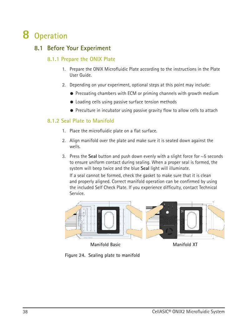
8.1.2 Seal Plate to Manifold
1. Place the microfluidic plate on a flat surface.
2. Align manifold over the plate and make sure it is seated down against the wells.
3. Press the Seal button and push down evenly with a slight force for ~5 seconds to ensure uniform contact during sealing. When a proper seal is formed, the system will beep twice and the blue Seal light will illuminate.If a seal cannot be formed, check the gasket to make sure that it is clean and properly aligned. Correct manifold operation can be confirmed by using the included Self Check Plate. If you experience difficulty, contact Technical Service.
Figure 24. Sealing plate to manifold
Manifold Basic Manifold XT

CellASIC® ONIX2 Microfluidic System 39
8.1.3 Set Up Microscope for Imaging
1. Place plate/manifold on your microscope stage. Make sure plate is flat and secure.
2. Use your microscope control software to set up a multi-position and multi-timepoint acquisition. There are many options for imaging; one typical approach is described here:
● Select the image locations. Some microscopy software includes plate maps of the ONIX Plates and you can use these to set up your microscope for automated image acquisition. Alternatively you can select your positions manually after placing the plate on the microscope.
Figure 25. Several locations within a single unit may be selected for imaging
● Set up the image sequence. Often one brightfield and multiple fluorescent images are taken at each location and each timepoint. Performing image or laser-based autofocus at the beginning of each timepoint and location is useful to account for the potential of thermal drift in long experiments.
8.1 Before Your Experiment, continued

CellASIC® ONIX2 Microfluidic System40
8.2 Creating and Running a New Experiment
8.2.1 Create Experiment File
1. Click New Experiment on the opening screen or File menu.
2. In the Select Plate Type dialogue, select the desired plate type (e.g., M04S-03 - Plate for Mammalian Cells) and click OK.
Figure 26. Plate type selection

CellASIC® ONIX2 Microfluidic System 41
8.2.2 Run Plate Setup SequencesIf cells were not loaded previously using a passive surface tension or gravity method, you may do active cell loading now.
1. Click Manual Mode to navigate to the Manual Mode tab, if not already there.
Figure 27. Cell loading
A
2. If desired, adjust the cell load sequence by clicking Edit next to the Run cell loading sequence button (A). Using the default setting specific to each plate is recommended, however, optimization may be required depending on the cell type and/or concentration. For some plate types, cell loading can be achieved without using the ONIX2 System. For example, the M04S-03 microfluidic plates can be gravity-loaded by pipette. In such cases, this cell loading sequence can be skipped.
8.2 Creating and Running a New Experiment, continued

CellASIC® ONIX2 Microfluidic System42
3. A protocol editor window will open. Modify the cell load sequence as desired and click OK.
Figure 28. Edit cell loading sequence
NOTE: Plate Setup sequences are saved as part of your experiment file. If you want to customize a setup sequence and save it for future use, simply save your experiment file and next time you would like to run the same sequence choose New experiment based on previous and select the file you just saved. Your customized setup sequences will be available and you can revert to the default sequences at anytime by clicking Reset.
8.2 Creating and Running a New Experiment, continued
CellASIC® ONIX2 Microfluidic System 43
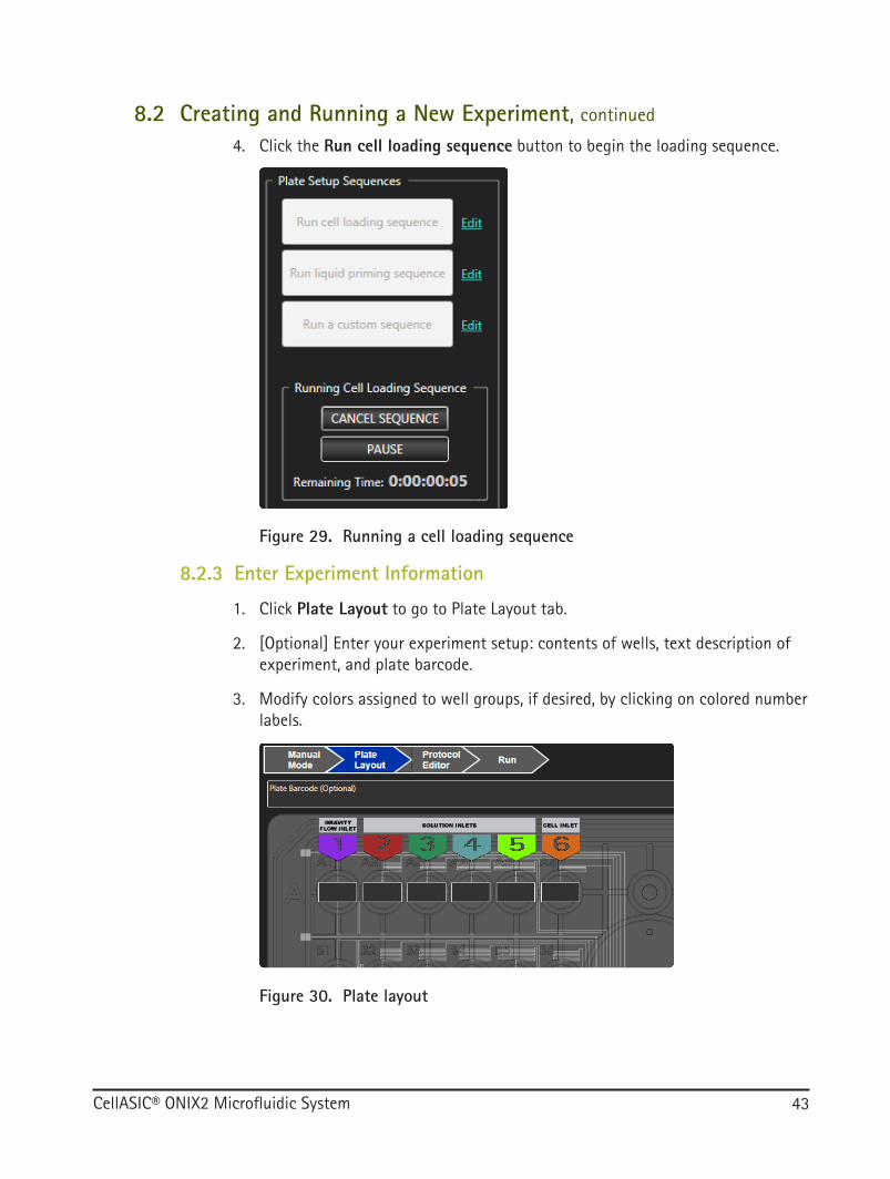
4. Click the Run cell loading sequence button to begin the loading sequence.
Figure 29. Running a cell loading sequence
8.2.3 Enter Experiment Information
1. Click Plate Layout to go to Plate Layout tab.
2. [Optional] Enter your experiment setup: contents of wells, text description of experiment, and plate barcode.
3. Modify colors assigned to well groups, if desired, by clicking on colored number labels.
Figure 30. Plate layout
8.2 Creating and Running a New Experiment, continued

CellASIC® ONIX2 Microfluidic System44
8.2.4 Create the Protocol
1. Click Protocol Editor (A) to go to the Protocol Editor tab.
Figure 31. Protocol editor
B
A C
2. Add and modify perfusion, pause, temperature set, and gas set steps as desired.
NOTE: Each step within a protocol can be edited using the Step Editor pane, which is displayed on the right (B) when a single step is selected.
● Right click on a step or multiple steps to copy and paste.
● Select multiple steps and right click to create repeat loops.
● Refer to Menu Items and Advanced Features section for more details.
8.2 Creating and Running a New Experiment, continued

CellASIC® ONIX2 Microfluidic System 45
8.2.5 Run the Experiment
1. Click Run (C in Figure 31) to go to the Run tab.
2. Click Start Run to open the final Pre-run Check dialogue. If the experiment needs to be saved, or if there are errors or warnings you will be notified here.
Figure 32. Pre-run check dialogue
3. When the experiment is ready, click Run. Your experiment is now running.
NOTE: You may pause an experiment either programmatically in the protocol or manually by clicking Pause. If paused programmatically, there is an option to Keep well groups open during pause, otherwise flow will be stopped while environmental control is continued during the pause. While paused with no flow, you may unseal and reseal plate, either by pressing the Seal button on the system or by clicking Seal or Unseal from the Tools menu. Click Resume to resume flow and continue execution of the protocol. A record of the pause is recorded in the run data and shown by a dashed mark on the Dynamic Timeline.
8.2 Creating and Running a New Experiment, continued

CellASIC® ONIX2 Microfluidic System46
Figure 33. Experiment will pause if an error occurs during a run
NOTE: If a warning condition occurs, e.g., gas supply low, it will be recorded in the experiment data. If an error condition occurs, e.g., the seal to plate is lost during execution of a protocol, the experiment will pause and the event will be recorded in the experiment data.
Notifications of an error or warning can be sent via email or text message; see Menu Items and Advanced Features to turn on this feature.
Correct the error, if possible (refer to Troubleshooting section) and click Clear Errors (Figure 33) to acknowledge. Then click Resume (Figure 34) to continue execution of the protocol.
Figure 34. Experiment may be resumed after the error has been addressed
8.2 Creating and Running a New Experiment, continued

CellASIC® ONIX2 Microfluidic System 47
8.3 Repeating a Previous Experiment with Minimal Clicks
8.3.1 Create Experiment File Based on a Previous Experiment
1. Click New experiment based on previous on the opening screen or File menu.
2. In the file browser find your previous experiment and click Open.
8.3.2 Run Plate Setup Sequences
1. On the Manual Mode tab you may click Run cell loading sequence and wait for cell load sequence to complete.
8.3.3 Edit Experiment Information
1. Click Plate Layout to go to the Plate Layout tab.
2. Enter plate barcode (not required, but recommended).
3. Edit any plate layout information that is new for this experiment.
Figure 35. Protocol editor
B
A C
8.3.4 Run the Experiment
1. Click Run to go to the Run tab.
2. Click Start Run to open the final Pre-run Check dialogue.
3. Click Save to save your experiment.
4. Click Run.

CellASIC® ONIX2 Microfluidic System48
8.4 Using the Mini-view
8.4.1 Begin Experiment
1. Launch application.
2. Click New Experiment on opening screen.
3. In the Select Plate Type dialogue, select the desired plate type (e.g., M04S-03 - Plate for Mammalian Cells) and click OK.
8.4.2 Open Plate Mini-view
1. On the Manual Mode tab, click the Mini-View button icon to open the plate mini-view. The plate mini-view is a small control window which can float on top of other windows and is intended to be used in parallel with your microscopy software.
2. Click Always on Top (A) to make mini-view float above other applications.
Figure 36. Mini-view on top
A
B

CellASIC® ONIX2 Microfluidic System 49
8.4.3 Operate the ONIX2 Manually
1. If desired, click Dual Pressure Mode (B in Figure 36) to activate secondary pressure.
2. Set pressures X and Y (C in Figure 37).
3. Click on Well groups (D) and Pressure Select (E) buttons to activate flows. The Unlock all well group access lock icon (F) allows manual activation of well groups other than the solution inlets.
Figure 37. Plate Mini-view with two well groups active and secondary pressure enabled
C
D
E
F

CellASIC® ONIX2 Microfluidic System50
8.5 Viewing and Exporting Data from a Previously Run Experiment
8.5.1 Open Experiment File
1. Click Open Previous Experiment on opening screen.
2. In the file browser find your previous experiment and click Open.
8.5.2 View Run Data
3. Click Run to go to the Run Tab.
4. Run data is shown in table format and can also be viewed by dragging the slider in the dynamic timeline.
Figure 38. Run tab showing run data

CellASIC® ONIX2 Microfluidic System 51
8.5.3 Export Data
1. Click Export to export the collected run data in TSV (tab-separated value) text format. The file can be opened using standard spreadsheet applications.
2. In file browser, select file name and location.
3. Click Save.
NOTE: The experiment summary can also be exported in PDF format by selecting the File menu and clicking Print Experiment Report.
Figure 39. Example of printed experiment report
CellASIC® ONIX2 Experiment Report
CellASIC® ONIX2 Experiment Report

CellASIC® ONIX2 Microfluidic System52
9 Maintenance and Cleaning
Y WARNING Y ATTENTIONPerform only the maintenance procedures described in this manual and observe the relevant safety precautions. Failure to do so may cause property damage or personal injury.Maintenance or repair procedures not described in this manual should be performed only by an EMD Millipore Corporation service engineer. Tampering with or alterations to the CellASIC® ONIX2 Microfluidic System, Manifolds and/or other components may void the warranty. Refer to the Technical Assistance section for information on contacting Technical Service.
Ne réaliser que les opérations de maintenance décrites dans ce manuel et prendre les précautions de sécurité adéquates. Le non-respect de ces exigences peut provoquer des dommages matériels ou des blessures corporelles.Les procédures de maintenance ou de réparation non décrites dans ce manuel doivent être réalisées uniquement par un ingénieur de maintenance EMD Millipore Corporation. Altérer ou modifier le Système de microfluidique CellASIC® ONIX2, le Manifold et/ou d’autres composants est susceptible d’annuler la garantie. Se reporter à la section “Technical Assistance” pour de plus amples informations sur la façon de contacter notre Service technique.
9.1 Running a System Self CheckA system self check should be run periodically to confirm ideal operation of the ONIX2 System.
1. Before you begin: ● Connect the ONIX2 System to the computer via USB ● Turn on the power switch (rear panel) ● Establish connection with the software ● If you have premixed gas sources, make sure they are connected and gas valves are open
2. Click System and Manifold Self Check in the Tools menu to open the System and Manifold Self Check dialogue.
3. Click Run Self Check.
4. Follow the prompts on the screen.
5. When prompted, follow directions to seal manifold to Self Check Plate.
6. The self check takes several minutes to complete. All checks should state PASS. If any say FAIL, please send results file to Technical Service (detailed results are saved to the folder indicated; the link can be clicked to access the folder). WARNINGS indicate an issue that needs further investigation. For example, if the results state WARNING Unable to fully check gas environment, gas input not detected, confirm that gas inputs are connected. If they are and the warning is still present contact Technical Service.

CellASIC® ONIX2 Microfluidic System 53
Figure 40. Example System and Manifold self check result with a gas input warning
9.2 Cleaning the CellASIC® ONIX2 Microfluidic SystemWipe dust off outer surface of system enclosure. Do not allow liquid to enter the system while cleaning.
9.3 Cleaning the GasketRemove the gasket from manifold periodically and clean gently with soap and water. Rinse with distilled water and/or 70% ethanol and shake off excess liquid. Lay gasket back onto manifold with holes properly aligned; do not stretch gasket during alignment. Set manifold in upright position to avoid settling of dust on gasket and allow to air dry.
For sanitization prior to experiment, gasket can be wiped or sprayed lightly with 70% ethanol and blotted dry with a lint-free cloth.
9.4 Gasket/Manifold AssemblyIf gasket is detached from the manifold, re-assemble using the following method:
1. Check cleanliness of the gasket; lint and particles may affect system operation. To clean the gasket, follow cleaning instructions above.
2. Match the outline shape of gasket to manifold.
3. Align and insert gasket oval lip into the manifold viewing oval.
4. Lay gasket flat onto manifold surface.
9.1 Running a System Self Check, continued

CellASIC® ONIX2 Microfluidic System54
5. Make slight adjustments to gasket/manifold position so gasket and manifold align hole-to-hole (black and green arrows below). Do not stretch gasket.
Figure 41. Attachment of gasket to manifold
Manifold viewing oval
Gasket oval lip
9.5 Cleaning the Manifold and TubingThe glass on the top of the CellASIC® ONIX2 Manifold XT and Manifold Basic can be gently cleaned with 70% ethanol or a glass cleaner.
NOTE: Manifold components are not autoclavable.
If fluid enters the manifold tubing during the course of an experiment, it should be cleaned as described below, and the filters should be replaced. A wet filter will interfere with proper functioning of the system.
NOTE: The manifold cleaning sequence takes approximately 5 minutes to complete, but may require an overnight air drying step before all tubing is dry and ready for use in an experiment.
1. Fill the center region of the CellASIC® ONIX2 Cleaning Plate with distilled water or hydrogen peroxide (3–6%) up to the max fill indicator line.
CAUTION: DO NOT use ethanol in the Cleaning Plate, as the ethanol will penetrate the protective filters in the Filter Multiconnector during the cleaning sequence.
MISE EN GARDE: NE PAS utiliser d’éthanol dans la Plaque de nettoyage car l’éthanol pénètre dans les filtres de protection du Filtre multi-connecteur au cours de la séquence de nettoyage.
9.5 Gasket/Manifold Assembly, continued

CellASIC® ONIX2 Microfluidic System 55
2. Seal the manifold to the cleaning plate.
Figure 42. Cleaning plate
3. Go to Tools→Cleaning Sequence to open the cleaning sequence interface.
4. Click Clean to begin the cleaning sequence.
Figure 43. Cleaning sequence interface
5. When cleaning sequence is complete, click Dry to expel the remaining liquid in the lines.
6. Cleaning and drying sequences can be repeated until manifold and tubing are acceptable. Replace the cleaning solution for each cleaning sequence for best results.
7. If after several dry sequences, tubing is not completely dry, include an overnight air drying step.
CAUTION: When cleaning the Manifold XT tubing, keep the manifold right side up and level, and do not expose the heat exchange module to liquid.
MISE EN GARDE : Lors du nettoyage de la tubulure du collecteur du Manifold XT, conserver le collecteur à l’endroit et de niveau, et ne pas exposer le module d’échange de chaleur à des liquides.
9.5 Cleaning the Manifold and Tubing, continued

CellASIC® ONIX2 Microfluidic System56
9.6 Replacing Manifold Luer FiltersIf the Luer filter fittings become wet and/or contaminated, they can be replaced easily. First remove the CellASIC® ONIX2 Filter Multiconnector from the front panel, then twist the lock collars counterclockwise to eject the filters. Attach new filters by placing them loosely on male Luer fittings inside the lock collar. You may need to adjust the orientation of the filter locking tabs to fit the filter into the lock collar. Gently twist each lock collar clockwise until the filter is brought up snug inside the collar. Discard wet/contaminated filters as they cannot be cleaned or reused. Replacement filters are included in the accessory box that comes with the system, and can be ordered separately as needed. See Ordering Information.
lock collars
unlock
Figure 44. Luer filter replacement

CellASIC® ONIX2 Microfluidic System 57
10 TroubleshootingGeneralObservation Potential Cause Recommended Action1. System does not
power onNo AC power Confirm that the power cable is securely connected
to the system and the power outlet.Verify that the outlet has power.Make sure the ON/OFF switch on the rear panel is in the ON position.
2. Error indicator light blinks
Error condition exists Check error/warning tray in ONIX2 Software to see what the error is. Follow recommended actions in Software Issues and Errors and Warnings tables below.
3. Ready indicator light blinks
Warning condition exists Check error/warning tray in ONIX2 Software to see what the warning is. Follow recommended actions in Software Issues and Errors and Warnings table below.
4. All three lights (Ready, Sealed, and Error) flash together
ONIX2 firmware has crashed Turn power off using ON/OFF switch on the rear panel, then turn back on. If problem persists, contact Technical Service.
5. Difficulty sealing manifold to plate
Downward force not applied evenly
Confirm recommended hand position as described in Before Your Experiment.
Debris on gasket Clean gasket as indicated in Maintenance and Cleaning.
Gasket misaligned Make sure gasket is aligned as described in Maintenance and Cleaning.
Plate surface damaged Inspect the plate for damage such as cracks or chips to the surface. If damage is found, contact Technical Service.
Loose Luer fittings/filters Tighten Luer fittings and filters as indicated in Installation and Setup.
Luer fittings not in correct order
Connect Luer fittings consecutively along the length of the Filter Multiconnector.
6. Plate fluid leakage Damaged plate Check plate for cracks. If cracks are found, contact Technical Service.
7. Fluid in the manifold lines
Culture chamber outlet wells were not emptied and they overflowed
Clean manifold and tubing and replace filters as described in Maintenance and Cleaning.For subsequent experiments, choose a slower flow rate and/or pause protocol midway to empty waste outlets.

CellASIC® ONIX2 Microfluidic System58
Software IssuesObservation Potential Cause Recommended Action1. Email Alert not working Connection to server failed Check information entered, internet connection,
and firewall settings.Email placed in junk folder Confirm that sender address is not blocked by
recipient email.
Errors and Warnings (may appear in status bar and error/warning tray)Error Potential Cause Recommended Action1. Seal lost Poorly formed seal Follow actions for “Difficulty sealing manifold to
plate” above.2. Pressure X/Y leakage
detectedLoose Luer fittings/filters on Filter Multiconnector
Tighten Luer fittings and filters as indicated in Maintenance and Cleaning.
Filter Multiconnector not fully inserted
Verify that Filter Multiconnector is pushed in all the way.
Microfluidic plate leakage Check plate for cracks. If cracks are found, contact Technical Service.
Debris on gasket Clean gasket as indicated in Maintenance and Cleaning.
3. Pump error Pump malfunction Contact Technical Service.4. Incompatible manifold
connectedONIX2 Microfluidic System not compatible with manifold
Update your software and firmware (see Settings - System Tab).
Warnings Potential Cause Recommended Action1. Gas A/B low Gas cylinder supply getting
lowReplace the gas cylinder.
2. Gas A/B empty or not connected
Gas cylinder empty or not connected
Reconnect or replace the gas cylinder.Make sure gas cylinder is connected to the correct gas inlet (i.e., the one that is selected in software).
3. Incorrect gas flow detected
Manifold tubing pinched Ensure that tubing is not pinched and that gas flow is unobstructed.
Gas cylinder empty or not connected
Reconnect or replace the gas cylinder.
4. Manifold disconnected Poor electrical connection Verify that the manifold cable is securely inserted into connector on front panel of the system.
Attempting temperature control but using the ONIX2 Manifold Basic
If temperature control is desired, an ONIX2 Manifold XT must be connected.
10 Troubleshooting, continued

CellASIC® ONIX2 Microfluidic System 59
10 Troubleshooting, continued
Errors and Warnings (may appear in status bar and error/warning tray)Warnings Potential Cause Recommended Action1. Manifold unable
to reach target temperature
Operating temperature out of range; too warm or too cold
Cool or heat the room to specified operating temperature of 20-30 °C.
2. Manifold lower/upper blower timed out
Debris prevented blowers in ONIX2 Manifold XT from rotating
Confirm that there is no debris preventing blower operation.
If these corrective actions do not resolve the issue, run the Self Check (see Maintenance and Cleaning). Contact Technical Service and provide them with the self check results file.
11 SpecificationsGeneral
Dimensions 330 mm wide × 306 mm deep × 108 mm high (13 in. × 12 in. × 4.25 in.)
Weight 6.7 kg (14.75 lb)Power consumption 100–240 VAC, 50/60 Hz, 40 WCooling mode Air cooled (natural convection)Environmental conditions For indoor laboratory useOperating temperature 20 °C to 30 °CStorage temperature 5 °C to 35 °C
Flow ControlNumber of outputs 8 (each addressable by either of two pressure controllers)Pressure range -50 to 70 kPa (-7.25 to 10.2 psi)Pressure accuracy ± 1.5 kPa (0.22 psi)Pressure stabilization time within ± 5 kPa (0.73 psi) in < 5 seconds
Gas Environmental ControlControl capabilities Option to electronically select between two premixed gasses and
set flow rate to slow or fast.Gas input requirements Clean, dry, premixed gas mixtures containing air, CO2, N2, and
O2 (up to 25%), regulated to between 100 kPa and 700 kPa (15 psi and 100 psi)

CellASIC® ONIX2 Microfluidic System60
Gas Environmental Control, continued
Gas consumption Slow flow: 5 mL/min ± 2 mL/min Fast flow: 50 mL/min ± 20 mL/min
Cell culture region gas environment accuracy
For slow gas flow: < 10% deviation from delivered gas concentration For fast gas flow: < 2% deviation from delivered gas concentration
Temperature Control (Requires CAX2-MXT20 CellASIC® ONIX2 Manifold XT)Temperature control range Room temperature to 40 °CControl method Bi-directional PIDAccuracy of sample chamber
temperature± 1 °C (using the CAX2-ACT20 ONIX2 Temperature Calibration Plate
can result in accuracy as high as ± 0.2 °C)Stability of sample chamber
temperature± 0.2 °C
Rise time (25 °C to 37 °C) < 30 minutesCooling time (37 °C to 25 °C) < 30 minutes
Computer RequirementsOperating system Windows® 7 or Windows® 10 (32 or 64 bit)Random access memory (RAM) 4 GB or higherMonitor 1920 × 1080 resolution or higherHard drive 200 MB or higherHardware interface USB 2.0 or higher
Microscope RequirementsType Inverted microscopeMinimum stage
weight capacityFor CAX2-MXT20 CellASIC® ONIX2 Manifold XT and filled plate:
310 g (10.9 oz)For CAX2-MBC20 CellASIC® ONIX2 Manifold Basic and filled plate:
200 g (7.1 oz)Minimum condenser working
distanceFor CAX2-MXT20 CellASIC® ONIX2 Manifold XT: 28 mm (1.1 in.) For CAX2-MBC20 CellASIC® ONIX2 Manifold Basic: 28 mm (1.1 in.)
Maximum condenser diameter For CAX2-MXT20 CellASIC® ONIX2 Manifold XT: 70 mm (2.8 in.) For CAX2-MBC20 CellASIC® ONIX2 Manifold Basic: no limit
11 Specifications, continued

CellASIC® ONIX2 Microfluidic System 61
12 Ordering InformationThis section lists catalogue numbers for the CellASIC® ONIX products. See Technical Assistance section for contact information. You can purchase these products on-line at www.millipore.com/cellasic.
Product Description Cat. No. Qty/PkCellASIC® ONIX2 Microfluidic System
(includes ONIX2 Filter Multiconnector, Software USB Drive, Replacement Filter Pack, Accessory Fittings, Self Check Plate, Cleaning Plate)
CAX2-S0000 1
CellASIC® ONIX2 Manifold XT (Temperature Controlled) CAX2-MXT20 1
CellASIC® ONIX2 Manifold Basic (No Temperature Control) CAX2-MBC20 1
Replacement Parts and AccessoriesCellASIC® ONIX2 Filter Multiconnector (includes filters) CAX2-AMC00 1CellASIC® ONIX2 Software USB Drive CAX2-SSW01 1CellASIC® ONIX2 Gasket CAX2-AGK20 1CellASIC® ONIX2 Self Check Plate CAX2-ASP20 1CellASIC® ONIX2 Cleaning Plate CAX2-ACP20 1CellASIC® ONIX2 Replacement Filter Pack (9 × 4 mm and 1 × 13 mm Millex® 0.45 PTFE filters)
CAX2-AFP00 1
CellASIC® ONIX2 Accessory Fittings CAX2-ABF00 1CellASIC® ONIX2 Temperature Calibration Plate CAX2-ACT20 1CellASIC® ONIX2 Premixed Gas Regulator (for use with 103 L or 112 L gas cylinders with a C10 connection)
CAX2-ABR00 1
CellASIC® ONIX Microfluidic PlatesWe offer a wide variety of plates for your application needs. Below are some of our most common plates. For a complete list of plate types, please visit www.millipore.com/cellasic.
CellASIC® ONIX plate for haploid yeast cells (4-chamber, trap heights of 3.5, 4.0, and 4.5 µm)
Y04C-02-5PK 5
CellASIC® ONIX plate for diploid yeast cells (4-chamber, trap heights of 5, 6, and 7 µm)
Y04D-02-5PK 5
CellASIC® ONIX plate for bacteria cells (4-chamber, trap heights of 0.7, 0.9, 1.1, 1.3, 2.3, and 4.5 µm)
B04A-03-5PK 5
CellASIC® ONIX switching plate for mammalian cells (4-chamber) M04S-03-5PK 5CellASIC® ONIX open-top plate for mammalian cells (4-chamber) M04L-03-5PK 5CellASIC® ONIX gradient plate for mammalian cells (4-chamber) M04G-02-5PK 5CellASIC® ONIX plate for Chlamydomonas cells (4-chamber, chamber height of 5 µm with 4 µm pocket)
C04A-01-5PK 5

CellASIC® ONIX2 Microfluidic System62
13 Technical AssistanceFor more information, contact the office nearest you. In the U.S., call 1-800-645-5476. Outside the U.S., go to our web site at www.millipore.com/offices for up-to-date worldwide contact information. You can also visit the tech service page on our web site at www.millipore.com/techservice.
14 Manufacturer
M
EMD Millipore Corporation Hayward, CA 94545 U.S.A.
15 Standard WarrantyThe applicable warranty for the products listed in this publication may be found at www.millipore.com/terms (“Conditions of Sale”).