a microfluidic device approach to generate hollow … microfluidic device... · a microfluidic...
TRANSCRIPT

A microfluidic device approach to generate hollow alginate microfibers with controlledwall thickness and inner diameterUyen H. T. Pham, Madiha Hanif, Amit Asthana, and Samir M. Iqbal Citation: Journal of Applied Physics 117, 214703 (2015); doi: 10.1063/1.4919361 View online: http://dx.doi.org/10.1063/1.4919361 View Table of Contents: http://scitation.aip.org/content/aip/journal/jap/117/21?ver=pdfcov Published by the AIP Publishing Articles you may be interested in A low cost design and fabrication method for developing a leak proof paper based microfluidic device withcustomized test zone Biomicrofluidics 9, 026502 (2015); 10.1063/1.4918641 Facile fabrication processes for hydrogel-based microfluidic devices made of natural biopolymers Biomicrofluidics 8, 024115 (2014); 10.1063/1.4871936 A pneumatic valve controlled microdevice for bioanalysis Biomicrofluidics 7, 054116 (2013); 10.1063/1.4826158 Bromo-oxidation reaction in enzyme-entrapped alginate hollow microfibers Biomicrofluidics 5, 024117 (2011); 10.1063/1.3605512 Thiolene-based microfluidic flow cells for surface plasmon resonance imaging Biomicrofluidics 5, 026501 (2011); 10.1063/1.3596395
[This article is copyrighted as indicated in the article. Reuse of AIP content is subject to the terms at: http://scitation.aip.org/termsconditions. Downloaded to ] IP:
12.96.1.130 On: Thu, 04 Jun 2015 04:17:53

A microfluidic device approach to generate hollow alginate microfiberswith controlled wall thickness and inner diameter
Uyen H. T. Pham,1,2,3 Madiha Hanif,1,2,3 Amit Asthana,4,a) and Samir M. Iqbal1,2,3,5,6,b)
1Department of Bioengineering, University of Texas at Arlington, Arlington, Texas 76010, USA2Nano-Bio Lab, University of Texas at Arlington, Arlington, Texas 76019, USA3Nanotechonology Research Center, University of Texas at Arlington, Arlington, Texas 76019, USA4CSIR-Centre for Cellular & Molecular Biology, Habsiguda, Uppal Road, Hyderabad � 500 007, India5Department of Electrical Engineering, University of Texas at Arlington, Arlington, Texas 76011, USA6Department of Urology, University of Texas Southwestern Medical Center at Dallas, Dallas, Texas 75235,USA
(Received 26 January 2015; accepted 17 April 2015; published online 3 June 2015)
Alginate is a natural polymer with inherent biocompatibility. A simple polydimethylsiloxane
(PDMS) microfluidic device based self-assembled fabrication of alginate hollow microfibers is pre-
sented. The inner diameter as well as wall thickness of the microfibers were controlled effortlessly,
by altering core and sheath flow rates in the microfluidic channels. The gelation/cross-linking
occured while the solutions were ejected. The microfibers were generated spontaneously, extruding
out of the outlet microchannel. It was observed that the outer diameter was independent of the flow
rates, while the internal diameter and wall thickness of the hollow fibers were found to be functions
of the core and sheath flow rates. At a constant sheath flow, with increasing core flow rates, the in-
ternal diameters increased and the wall thicknesses decreased. At a fixed core flow, when sheath
flow rate increased, the internal diameters decreased and the wall thickness increased. The immobi-
lization of enzymes in such hollow microfibers can be a potential application as microbioreactors.VC 2015 AIP Publishing LLC. [http://dx.doi.org/10.1063/1.4919361]
INTRODUCTION
Alginate is a polysaccharide polymer that is derived from
brown algae (Phaeophyceae).1 Its chemical structure consists
of block copolymer of (1,4)-b-D-mannuronate (M) and a-L-
guluronate (G) contents.2 Alginate hydrogel can be made by
different methods such as ionic crosslinking, covalent cross-
linking, or thermal gelation. The simplest alginate hydrogel
formation is through ionic crosslinking. During gelation, only
G blocks crosslink with divalent cations which is described as
an “egg-box” model.2 Different chemical agents have variety
of effects on the gelation of alginate, with calcium chloride
(CaCl2) being the most commonly used. Calcium chloride is a
highly water soluble chemical reagent; its Ca2þ cations cross-
link with alginate via ionic diffusion.3 Moreover, it rapidly
increases the gelation rate of the alginate hydrogel. The physi-
cal and chemical properties of alginate depend on the source
of alginate which may contain various lengths of M and G res-
idue components and selective binding sites for multivalent
cations. In addition, the sol-to-gel transition of alginate during
gel formation is not affected by temperature. These unique
characteristics have made alginate a promising candidate to
mimic biological matrices.1 Alginate hydrogel possesses
many natural characteristics that make it the most suitable ma-
terial for many biological applications such as enzyme immo-
bilization, drug delivery, tissue engineering, food industry,
pharmaceutical industry, wound dressing, etc.
Over last two decades, the applications of microstructures
like microfibers, microspheres, microstrips, microbeads, etc.,
have steadily increased in areas like tissue engineering, bio-
technology, and analytical chemistry.4 The efficiency of
chemical functionalization, biocompatible surface derivation,
and molecular immobilization depends on the type of micro-
structures. For example, many studies have demonstrated the
encapsulation and culture of cells in the alginate hydrogel
microfibers. The common characteristic of the fabricated fiber
microstructures for cell culturing is to possess very thin side
walls. These fiber-shaped microstructures can be used to
mimic the 3D constructs of complex tissues in vivo like blood
vessels, muscle fiber, neural nerves, etc.5 The thin side wall
allows the cultured cells to proliferate and migrate into 3D
functional morphology. However, these structures are not suit-
able for enzyme immobilization applications. The thin side
walls of the fiber microstructure cause massive and rapid leak-
age from the microfibers.
Enzyme immobilization is a method to confine enzymes
in the supporting matrix. The common microstructures for
enzyme immobilization are microbeads or microfibers. It is
very difficult to control the gelation rate of microbeads and
thus their size distribution lacks uniformity.6 The previous
studies have reported limitations due to low encapsulation
efficiency and diffusion of enzymes through the thin walls of
microbeads/microspheres. Therefore, there is a need for a
coating of cationic polymer like chitosan.7–9 However, the
coating layers cause toxicity to the immobilized molecules.10
Compared to microbeads, microfibers have a larger
surface-to-volume ratio. The fiber-based techniques like
electrospinning, wetspinning, interfacial complexation, or
a)Email: [email protected])Present address: University of Texas at Arlington, 500 S. Cooper St #217,
Box 19072, Arlington, Texas 76019, USA. Email: [email protected].
Telephone: þ1-817-272-0228. Fax: þ1-817-272-7458.
0021-8979/2015/117(21)/214703/6/$30.00 VC 2015 AIP Publishing LLC117, 214703-1
JOURNAL OF APPLIED PHYSICS 117, 214703 (2015)
[This article is copyrighted as indicated in the article. Reuse of AIP content is subject to the terms at: http://scitation.aip.org/termsconditions. Downloaded to ] IP:
12.96.1.130 On: Thu, 04 Jun 2015 04:17:53
thermal spinning have been employed to fabricate the micro-
fibers. The microfibers have been used as substrates or for
reinforcement in biotechnology. These production methods
are, however, expensive, hard to control, and incompatible
with biological molecules due to high electric fields involved
or harshness of the chemical agents used.11
In this work, the micro-devices were fabricated and used
for facile synthesis of hollow alginate microfibers. As com-
pared to other fiber-based techniques, the microfluidic plat-
form is: (1) simple, (2) rapid, and (3) provided superior
control over microfiber properties. In the present method no
chemical agents or high electric fields were employed to gen-
erate microfibers. The microfibers were fabricated in the
microfluidic channels by coaxial flow reaction. Divalent cati-
ons exchange and crosslink with pre-polymer chains to form
the microfiber structure. The fibers were generated spontane-
ously and extruded out of the channel after certain residence
time. Traditionally, soft lithography is used to fabricate com-
plex devices. For example, Kang12 designed a single micro-
fluidic device that contained coaxial-flow channels and
rectangular channels. While rectangular channels could be
fabricated easily, cylindrical channels require templates that
can be removed after polymer gelation. In addition, the pro-
cess of fabricating rectangular and cylindrical microchannels
by soft lithography is time consuming and not suitable for a
wet lab environment due to the requirement of cleanroom
and specialized tools.
In 2004, Jeong et al.13 introduced a new method to fabri-
cate the cylindrical microchannels using embedded glass
capillaries. The glass capillary-based platform has been used
to fabricate poly (lactic-co-glycolic acid) (PLGA) microfibers
for 3D cell culture,14 alginate microfibers for cellular loading,4
and to create microfibers to control the cell orientation.15
With the glass capillary-based systems, the fabricated micro-
fibers contained thin side walls. Thus these fibers could only
be used for cell harvesting. Moreover, changing the flow rate
controlled the outer diameter of the generated microfibers.
The glass capillary-based system is simple and rapid, how-
ever, it is labor-intensive, requires certain skill sets and the
use of specialized tools.12 Moreover, none of the previous
studies have reported the relationship between flow rates and
internal diameter or wall thickness of hollow microfibers.
In this paper, we introduce a PDMS microfluidic de-
vice fabricated using an embedded template method.8,16
Unlike the glass capillary-based platform, our microfluidic
devices were fabricated completely in PDMS. The bench-
top embedded template method of fabrication was simple,
rapid, and cost-effective. This device was then used to
generate long continuous hollow microfibers. The inner
diameters and the wall thickness of alginate hollow
microfibers were controlled by changing the flow rates.
The alginate microfibers were characterized for their
diameters and the wall thicknesses with respect to the
core and sheath flow rate. We show that: (1) at a constant
sheath flow with an increasing core flow, the internal
diameters increased and wall thicknesses decreased; and
(2) at a constant core flow with an increasing sheath flow,
the internal diameters decreased and the wall thicknesses
increased.
EXPERIMENTAL
Materials
PDMS was prepared using Sylgard 184 kits purchased
from Ellsworth Adhesives (Dow Corning, Midland, MI,
USA). The kit contained PDMS base and curing agent.
Sodium alginate (Protanal LF 10/60 FT, high gel-strength
and medium viscosity, pH 6.0–8.0 of 1% solution) was a gift
from FMC BioPolymer (Philadelphia, PA, USA). Anhydrous
calcium chloride (BioReagent, �96.0%) was obtained from
Sigma-Aldrich (St. Louis, MO, USA).
Fabrication of PDMS microfluidic device
The design of the microfluidic device was a “diverged
Y-shape.” This was an optimum design because it qualified
the following criteria: (1) all pre-polymer and chemical
agents merged at the intersection, and (2) it prevented back-
flow through the inlets. The microfluidic device was fabri-
cated by a simple embedded template method described by
Asthana et al.16 The device contained three inlets and one
outlet port (Fig. 1). The three inlets were connected 1 mm
away from the end of the outlet microchannel.
As indicated in Fig. 2, the outlet template was a plastic
hollow capillary tube with an outer diameter of 0.7 mm. A
small hole was punched through the plastic hollow capillary
using a small BD needle (26 G � 5/8 in.). The distance from
one end of the plastic tube to the punched hole was 1 mm. A
long straight aluminium wire was introduced through the
hole. The diameter of the wire was 0.4 mm.
This wire was bent at approximately 45� to form a
V-shape. For the main inlet template, another wire was
attached at the end of the plastic hollow tube. Larger 1 mm
diameter plastic hollow capillaries were placed at the open-
end of three inlets and outlet.
As shown in Fig. 2, the embedded template was secured
on the Petri dish using double-side tape. The mixture of
PDMS pre-polymer and curing agent (ratio 10:1) was poured
to completely cover the template. The whole assembly was
put in a vacuum chamber for degassing. The Petri dish with
the template covered in PDMS was then cured at 150 �C.
Thereafter, all the templates were pulled out from the cured
PDMS matrix followed by oxygen plasma exposure of as-
fabricated device for 10–15 min. The oxygen plasma treat-
ment made the PDMS surface hydrophilic due to the intro-
duction of silanol (Si—OH) groups to the surface.
Synthesis of hollow alginate microfibers
For fabrication of the alginate hollow fibers, the experi-
ment was set up as shown in Fig. 3. The alginate microfiber
was generated in a microfluidic device using coaxial-flow in-
fly ionic crosslinking. A 2% alginate solution (w/v) was run
through the side channels as sheath flow. A 20 mM CaCl2aqueous solution was introduced from the central channel as
core flow. When the three fluids merged at the intersection,
the gelation mechanism spontaneously began and ionic
crosslinking occurred between sodium alginate and calcium
chloride. The unreacted CaCl2 diffused through to the walls
of the hollow fiber walls and acted as a lubricant, which
214703-2 Pham et al. J. Appl. Phys. 117, 214703 (2015)
[This article is copyrighted as indicated in the article. Reuse of AIP content is subject to the terms at: http://scitation.aip.org/termsconditions. Downloaded to ] IP:
12.96.1.130 On: Thu, 04 Jun 2015 04:17:53

assisted in smooth extrusion of hollow fibers from the outlet
channel without requiring any additional pressure.4 By
adjusting the flow rates of CaCl2 core and alginate sheath
flow easily controlled the diameter of the alginate hollow
microfiber. The relationships between the flow rates and
diameters of the hollow microfibers were investigated by
two sets of experiments: (1) changing core flow at a fixed
sheath flow rate, and (2) changing the sheath flow at a con-
stant core flow rate.
In the first set of experiments, the sheath flow was kept
constant at 0.05 ml/min while the core flow was changed to
0.42, 0.50, 0.75, and 0.90 ml/min. In the second set of
FIG. 1. The template method. (a) The
aluminium wire was inserted through
the hole. (b) The wire was bent to form
a V-shape. (c) The single wire was
attached at other end of the plastic
tube. (d) The large plastic tubes were
placed at the open end of inlets and
outlet.
FIG. 2. Bench-top fabrication of the microfluidic device. (a) The diverged
Y-shape template platform has three inlet ports and one outlet. (b) The tem-
plate is fully covered by PDMS prepolymer and then placed in a vacuum
chamber. (c) The assembly is cured at 150 �C. (d)–(f) The templates are
pulled out leaving voids which work as microfluidic channels.
FIG. 3. The experiment setup. A 2% alginate solution is introduced from the
two side-channels and 20 mM CaCl2 is injected from the central channel.
The alginate and CaCl2 solutions merge at the intersection and crosslink.
The hollow microfiber is collected in a beaker of 100 mM CaCl2 solution.
214703-3 Pham et al. J. Appl. Phys. 117, 214703 (2015)
[This article is copyrighted as indicated in the article. Reuse of AIP content is subject to the terms at: http://scitation.aip.org/termsconditions. Downloaded to ] IP:
12.96.1.130 On: Thu, 04 Jun 2015 04:17:53
experiments, the sheath flow was changed to 0.01, 0.03, 0.05,
0.1, and 0.3 ml/min while the core flow was fixed at 0.50 ml/
min. The fabricated alginate fibers were immersed in a 100 mM
CaCl2 solution for 24 h to harden the microfibers.
For diameter and wall thickness characterization, the
fibers were imaged using an optical microscope. The lengths
of the fibers were kept at 4–6 cm, while the internal and outer
diameters were measured randomly at 10 different points on
the fiber. The wall thickness was calculated by subtracting
the internal diameter from the outer diameter. Each flow rate
experiment was repeated at least three times. The fiber diam-
eter characterizations were expressed as the mean and stand-
ard deviation. Linear relationships were seen between the
flow rates and the microfiber diameters.
RESULTS AND DISCUSSION
Characterization of hollow alginate microfiber
The single long hollow microfiber could be fabricated
continuously as long as the solutions were fed at the inlet
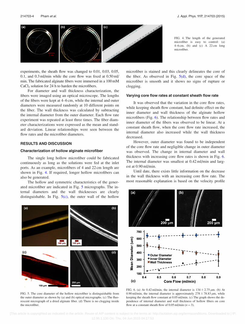
ports. As an example, microfibers of 4 and 22 cm length are
shown in Fig. 4. If required, longer hollow microfibers can
also be generated.
The hollow and symmetric characteristics of the gener-
ated microfiber are indicated in Fig. 5 micrographs. The in-
ternal diameters and the wall thicknesses are clearly
distinguishable. In Fig. 5(c), the outer wall of the hollow
microfiber is stained and this clearly delineates the core of
the fiber. As observed in Fig. 5(d), the core space of the
microfiber is smooth and it shows no signs of rupture or
clogging.
Varying core flow rates at constant sheath flow rate
It was observed that the variation in the core flow rates,
while keeping sheath flow constant, had definite effect on the
inner diameter and wall thickness of the alginate hollow
microfibers (Fig. 6). The relationship between flow rates and
inner diameter of the fibers was observed to be linear. At a
constant sheath flow, when the core flow rate increased, the
internal diameter also increased while the wall thickness
decreased.
However, outer diameter was found to be independent
of the core flow rate and negligible change in outer diameter
was observed. The change in internal diameter and wall
thickness with increasing core flow rates is shown in Fig. 6.
The internal diameter was smallest at 0.42 ml/min and larg-
est at 0.90 ml/min.
Until date, there exists little information on the decrease
in the wall thickness with an increasing core flow rate. The
most reasonable explanation is based on the velocity profile
FIG. 4. The length of the generated
microfiber is easy to control: (a)
4–6 cm. (b) and (c) A 22 cm long
microfiber.
FIG. 5. The core diameter of the hollow microfiber is distinguishable from
the outer diameter as shown by (a) and (b) optical micrographs. (c) The fluo-
rescent micrograph of a dried alginate fiber. (d) There is no clogging inside
the microfiber.
FIG. 6. (a) At 0.42 ml/min, the internal diameter is 134 6 2.75 lm. (b) At
0.90 ml/min, the internal diameter is approximately 278 6 78.83 lm, while
keeping the sheath flow constant at 0.05 ml/min. (c) The graph shows the de-
pendence of internal diameter and wall thickness of hollow fibers on core
flow at a constant sheath flow of 0.05 ml/min (n¼ 3).
214703-4 Pham et al. J. Appl. Phys. 117, 214703 (2015)
[This article is copyrighted as indicated in the article. Reuse of AIP content is subject to the terms at: http://scitation.aip.org/termsconditions. Downloaded to ] IP:
12.96.1.130 On: Thu, 04 Jun 2015 04:17:53
concept.17,18 At a constant sheath flow rate, with increasing
core flow rates, the velocity profiles between the core and
sheath flows are significantly different. This difference causes
increase in drag force of the two fluids that results in the
stretching of the core fluid. This phenomenon causes decrease
in diffusion of Ca2þ, which leads to less effective crosslinking
between Ca2þ and alginate, resulting in a thin fiber wall at a
high core flow rate. Another possible explanation of thinner
wall of hollow fiber is shift in the focus of sheath flow. At
core flow rates lower than the constant sheath flow, sheath
flow has focusing or pinching effect similar to hydrodynamic
focusing in droplet generation. On the other hand, at higher
core flow rates, this focusing reduces and core flow pushes the
sheath flow towards the wall of the microfluidic device caus-
ing thinner walls. To further explore the above explanation se-
ries of experiments were done with varying sheath flows at
constant core flow, as described below.
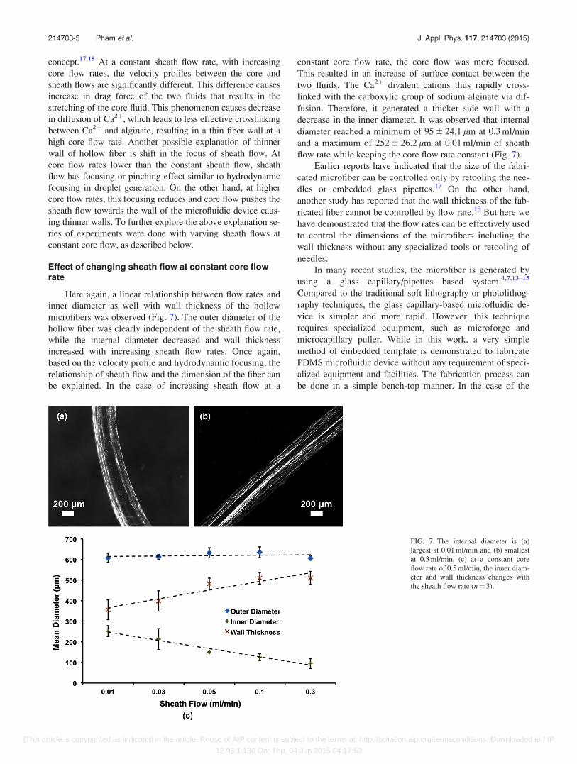
Effect of changing sheath flow at constant core flowrate
Here again, a linear relationship between flow rates and
inner diameter as well with wall thickness of the hollow
microfibers was observed (Fig. 7). The outer diameter of the
hollow fiber was clearly independent of the sheath flow rate,
while the internal diameter decreased and wall thickness
increased with increasing sheath flow rates. Once again,
based on the velocity profile and hydrodynamic focusing, the
relationship of sheath flow and the dimension of the fiber can
be explained. In the case of increasing sheath flow at a
constant core flow rate, the core flow was more focused.
This resulted in an increase of surface contact between the
two fluids. The Ca2þ divalent cations thus rapidly cross-
linked with the carboxylic group of sodium alginate via dif-
fusion. Therefore, it generated a thicker side wall with a
decrease in the inner diameter. It was observed that internal
diameter reached a minimum of 95 6 24.1 lm at 0.3 ml/min
and a maximum of 252 6 26.2 lm at 0.01 ml/min of sheath
flow rate while keeping the core flow rate constant (Fig. 7).
Earlier reports have indicated that the size of the fabri-
cated microfiber can be controlled only by retooling the nee-
dles or embedded glass pipettes.17 On the other hand,
another study has reported that the wall thickness of the fab-
ricated fiber cannot be controlled by flow rate.18 But here we
have demonstrated that the flow rates can be effectively used
to control the dimensions of the microfibers including the
wall thickness without any specialized tools or retooling of
needles.
In many recent studies, the microfiber is generated by
using a glass capillary/pipettes based system.4,7,13–15
Compared to the traditional soft lithography or photolithog-
raphy techniques, the glass capillary-based microfluidic de-
vice is simpler and more rapid. However, this technique
requires specialized equipment, such as microforge and
microcapillary puller. While in this work, a very simple
method of embedded template is demonstrated to fabricate
PDMS microfluidic device without any requirement of speci-
alized equipment and facilities. The fabrication process can
be done in a simple bench-top manner. In the case of the
FIG. 7. The internal diameter is (a)
largest at 0.01 ml/min and (b) smallest
at 0.3 ml/min. (c) at a constant core
flow rate of 0.5 ml/min, the inner diam-
eter and wall thickness changes with
the sheath flow rate (n¼ 3).
214703-5 Pham et al. J. Appl. Phys. 117, 214703 (2015)
[This article is copyrighted as indicated in the article. Reuse of AIP content is subject to the terms at: http://scitation.aip.org/termsconditions. Downloaded to ] IP:
12.96.1.130 On: Thu, 04 Jun 2015 04:17:53
glass capillary-based systems, the controllable flow rates
must be kept in narrow optimal ranges to avoid a spiral curl
of the fiber. The formation of spiral curl by the microfiber
can lead to clogging of the microchannel outlet. For exam-
ple, as reported by Shin et al.,4 in order to fabricate a straight
microfiber, the optimal CaCl2 sheath flow and alginate sam-
ple flow were 20 ml/min and 1 ll/min. Compared to previous
works, our technique is more efficient and easier to use. The
ranges of the flow rates are more flexible and the spiral curl
does not occur even at extremely high flow rates. For
instance, in our experiment, the highest alginate and CaCl2flow rates were 0.3 ml/min and 0.9 ml/min. The advantage of
this wide range of flow rates is that it will be a rapid process
when fabricating microfibers on a large scale with varying
dimensions irrespective of applications.
CONCLUSIONS
This work demonstrates a simple embedded template
method to fabricate PDMS microfluidic device without the
need for cleanroom or specialized equipment. The microflui-
dic devices used for the synthesis of alginate microfibers are
very simple and provide rapid means to generate microfibers.
The size of the fiber (diameters and wall thickness) is con-
trolled by merely changing the flow rates. The advantage of
this technique is that it can be used extensively for fabrica-
tion of bioreactors, and can be used for continuous monitor-
ing of analytes, their concentration, biotransformations, and
chemical synthesis.
ACKNOWLEDGMENTS
The authors acknowledge experimental assistance and
useful discussion with Young-Tae Kim, Mohammad R. Hasan,
Jeyantt S. Sankaran, Muhymin Islam, Wintana T. Kansai,
Phuong M. Nguyen, Dien V. Nguyen, and Thong Trinh. This
work was supported by the National Science Foundation
through an REU Supplement to grant ECCS-1201878.
1K. I. Draget and C. Taylor, “Chemical, physical and biological properties
of alginates and their biomedical implications,” Food Hydrocolloids 25(2),
251–256 (2011).2K. Y. Lee and D. J. Mooney, “Alginate: properties and biomedical
applications,” Prog. Polym. Sci. 37(1), 106–126 (2012).
3K. I. Draget, “Alginates,” in Handbook of Hydrocolloids, 2nd ed., edited
by G. O. Phillips and P. A. Williams (Woodhead Publishing, 2009), pp.
807–828.4S.-J. Shin, J.-Y. Park, J.-Y. Lee, H. Park, Y.-D. Park, K.-B. Lee, C.-M.
Whang, and S.-H. Lee, “‘On the fly’ continuous generation of alginate
fibers using a microfluidic device,” Langmuir 23(17), 9104–9108 (2007).5H. Onoe, T. Okitsu, A. Itou, M. Kato-Negishi, R. Gojo, D. Kiriya, K. Sato,
S. Miura, S. Iwanaga, and K. Kuribayashi-Shigetomi, “Metre-long cell-
laden microfibres exhibit tissue morphologies and functions,” Nat. Mater.
12(6), 584–590 (2013).6A. Ilyas, M. Islam, W. Asghar, J. U. Menon, A. S. Wadajkar, K. T.
Nguyen, and S. M. Iqbal, “Salt-leaching synthesis of porous PLGA nano-
particles,” IEEE Trans. Nanotechnol. 12(6), 1082–1088 (2013).7A. Asthana, K. H. Lee, S.-J. Shin, J. Perumal, L. Butler, S.-H. Lee, and D.-
P. Kim, “Bromo-oxidation reaction in enzyme-entrapped alginate hollow
microfibers,” Biomicrofluidics 5, 024117 (2011).8A. Asthana, K. H. Lee, K.-O. Kim, D.-M. Kim, and D.-P. Kim, “Rapid
and cost-effective fabrication of selectively permeable calcium-alginate
microfluidic device using ‘modified’ embedded template method,”
Biomicrofluidics 6, 012821 (2012).9Q. Liu, A. M. Rauth, and X. Y. Wu, “Immobilization and bioactivity of
glucose oxidase in hydrogel microspheres formulated by an
emulsification-internal gelation-adsorption-polyelectrolyte coating meth-
od,” Int. J. Pharm. 339(1), 148–156 (2007).10Y. A. Morch, I. Donati, B. L. Strand, and G. Skjak-Bræk, “Effect of Ca2þ,
Ba2þ, and Sr2þ on alginate microbeads,” Biomacromolecules 7(5),
1471–1480 (2006).11A. Tamayol, M. Akbari, N. Annabi, A. Paul, A. Khademhosseini, and D.
Juncker, “Fiber-based tissue engineering: Progress, challenges, and oppor-
tunities,” Biotechnol. Adv. 31(5), 669–687 (2013).12E. Kang, “Novel PDMS cylindrical channels that generate coaxial flow,
and application to fabrication of microfibers and particles,” Lab Chip
10(14), 1856–1861 (2010).13W. Jeong, J. Kim, S. Kim, S. Lee, G. Mensing, and D. J. Beebe,
“Hydrodynamic microfabrication via ‘on the fly’ photopolymerization of
microscale fibers and tubes,” Lab Chip 4(6), 576–580 (2004).14C. M. Hwang, A. Khademhosseini, Y. Park, K. Sun, and S.-H. Lee,
“Microfluidic chip-based fabrication of PLGA microfiber scaffolds for tis-
sue engineering,” Langmuir 24(13), 6845–6851 (2008).15C. M. Hwang, Y. Park, J. Y. Park, K. Lee, K. Sun, A. Khademhosseini,
and S. H. Lee, “Controlled cellular orientation on PLGA microfibers with
defined diameters,” Biomed. Microdevices 11(4), 739–746 (2009).16A. Asthana, K.-O. Kim, J. Perumal, D.-M. Kim, and D.-P. Kim, “Facile
single step fabrication of microchannels with varying size,” Lab Chip 9(8),
1138–1142 (2009).17T. Takei, S. Sakai, H. Ijima, and K. Kawakami, “Development of mamma-
lian cell-enclosing calcium-alginate hydrogel fibers in a co-flowing
stream,” Biotechnol. J. 1(9), 1014–1017 (2006).18S. Sakai, Y. Liu, E. J. Mah, and M. Taya, “Horseradish peroxidase/cata-
lase-mediated cell-laden alginate-based hydrogel tube production in two-
phase coaxial flow of aqueous solutions for filament-like tissues fab-
rication,” Biofabrication 5(1), 015012 (2013).
214703-6 Pham et al. J. Appl. Phys. 117, 214703 (2015)
[This article is copyrighted as indicated in the article. Reuse of AIP content is subject to the terms at: http://scitation.aip.org/termsconditions. Downloaded to ] IP:
12.96.1.130 On: Thu, 04 Jun 2015 04:17:53