ce niehoff a2-146- tg13f_uid1042010927391
TRANSCRIPT
Page 1TG13F
Table of ContentsSection A: Wiring Diagram ................................. 2 – 3 Section B: Basic Troubleshooting .............................4 Section C: A2-146/A2-153 Advanced Troubleshooting ..................5Section D: A2-214 Advanced Troubleshooting .... 6 – 8Section E: C653 w/A2-325 Advanced Troubleshooting .......... 9 – 11Section F: Advanced Troubleshooting .....................12
Battery Conditions Until temperatures of electrical system components stabilize, these conditions may be observed during cold start voltage tests.
• Maintenance/Low Maintenance Battery:— Immediately after engine starts, system volts measure lower than regulator setpoint and system amps measure at a medium level. — 3-5 minutes into charge cycle, volts increase and amps decrease. — 5-10 minutes into charge cycle, volts reach regulator setpoint or very close, and amps decrease to a minimum. — Low maintenance battery has same characteris- tics with slightly longer recharge times.
• Maintenance-free Battery:— Immediately after engine starts, system volts measure lower than regulator setpoint with low charging amps. — Once the charge cycle begins, low volts and low amps are still present. — After the alternator energizes, voltage will increase several tenths. Amps will increase gradually, then quickly, to medium to high amps. — Finally, volts will increase to setpoint and amps will decrease. The time it takes to reach optimum voltage and amperage will vary with engine speed, load, and ambient temperature.
• High-cycle Maintenance-free Battery:— These batteries respond better than standard maintenance-free. Charge acceptance of these batteries may display characteristics similar to maintenance batteries.
NOTICE
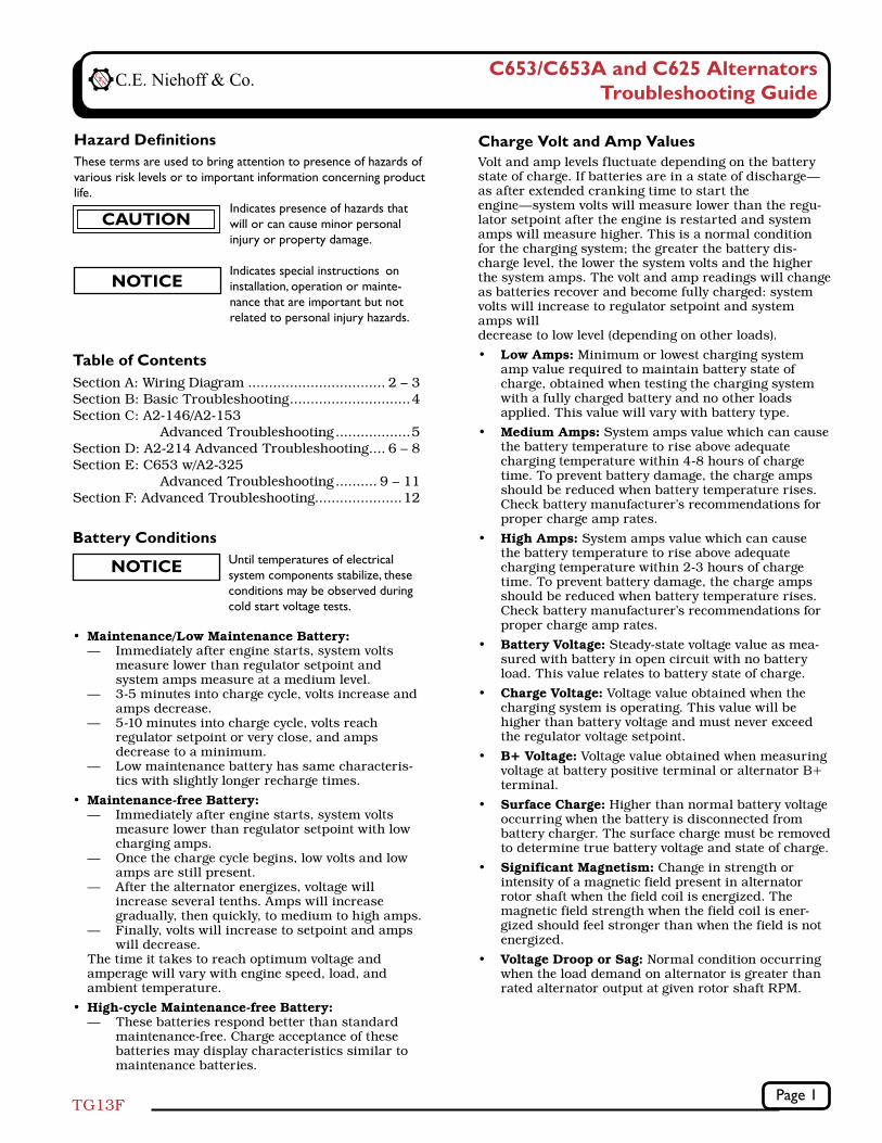
Hazard Definitions These terms are used to bring attention to presence of hazards of various risk levels or to important information concerning product life. Indicates presence of hazards that will or can cause minor personal injury or property damage.
Indicates special instructions on installation, operation or mainte- nance that are important but not related to personal injury hazards.
CAUTION
NOTICE
C653/C653A and C625 AlternatorsTroubleshooting Guide
Charge Volt and Amp ValuesVolt and amp levels fluctuate depending on the battery state of charge. If batteries are in a state of discharge—as after extended cranking time to start the engine—system volts will measure lower than the regu-lator setpoint after the engine is restarted and system amps will measure higher. This is a normal condition for the charging system; the greater the battery dis-charge level, the lower the system volts and the higher the system amps. The volt and amp readings will change as batteries recover and become fully charged: system volts will increase to regulator setpoint and system amps will decrease to low level (depending on other loads).
• Low Amps: Minimum or lowest charging system amp value required to maintain battery state of charge, obtained when testing the charging system with a fully charged battery and no other loads applied. This value will vary with battery type.
• Medium Amps: System amps value which can cause the battery temperature to rise above adequate charging temperature within 4-8 hours of charge time. To prevent battery damage, the charge amps should be reduced when battery temperature rises. Check battery manufacturer’s recommendations for proper charge amp rates.
• High Amps: System amps value which can cause the battery temperature to rise above adequate charging temperature within 2-3 hours of charge time. To prevent battery damage, the charge amps should be reduced when battery temperature rises. Check battery manufacturer’s recommendations for proper charge amp rates.
• Battery Voltage: Steady-state voltage value as mea-sured with battery in open circuit with no battery load. This value relates to battery state of charge.
• Charge Voltage: Voltage value obtained when the charging system is operating. This value will be higher than battery voltage and must never exceed the regulator voltage setpoint.
• B+ Voltage: Voltage value obtained when measuring voltage at battery positive terminal or alternator B+ terminal.
• Surface Charge: Higher than normal battery voltage occurring when the battery is disconnected from battery charger. The surface charge must be removed to determine true battery voltage and state of charge.
• Significant Magnetism: Change in strength or intensity of a magnetic field present in alternator rotor shaft when the field coil is energized. The magnetic field strength when the field coil is ener-gized should feel stronger than when the field is not energized.
• Voltage Droop or Sag: Normal condition occurring when the load demand on alternator is greater than rated alternator output at given rotor shaft RPM.
Page 2TG13F
Section A: Wiring Diagrams
B– terminal stud
P terminal
IGN terminal
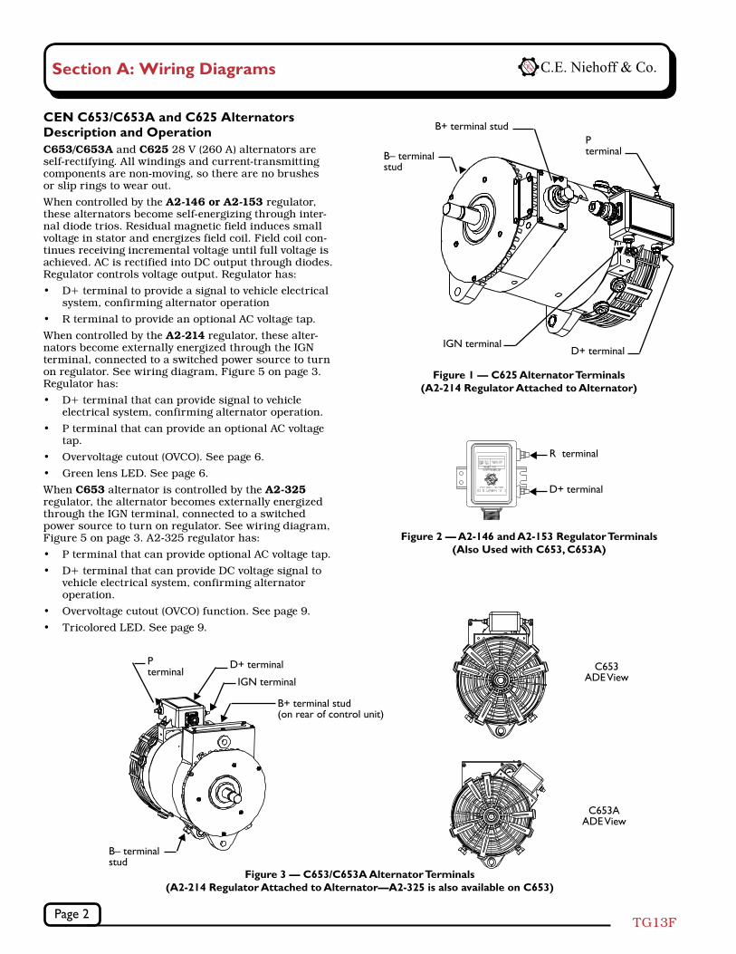
Figure 1 — C625 Alternator Terminals (A2-214 Regulator Attached to Alternator)
B+ terminal stud
D+ terminal
Figure 3 — C653/C653A Alternator Terminals (A2-214 Regulator Attached to Alternator—A2-325 is also available on C653)
B– terminal stud
D+ terminal
IGN terminal
B+ terminal stud(on rear of control unit)
P terminal
C653AADE View
C653ADE View
D+ terminal
R terminal
Figure 2 — A2-146 and A2-153 Regulator Terminals (Also Used with C653, C653A)
CEN C653/C653A and C625 Alternators Description and OperationC653/C653A and C625 28 V (260 A) alternators are self-rectifying. All windings and current-transmitting components are non-moving, so there are no brushes or slip rings to wear out.
When controlled by the A2-146 or A2-153 regulator, these alternators become self-energizing through inter-nal diode trios. Residual magnetic field induces small voltage in stator and energizes field coil. Field coil con-tinues receiving incremental voltage until full voltage is achieved. AC is rectified into DC output through diodes. Regulator controls voltage output. Regulator has:
• D+ terminal to provide a signal to vehicle electrical system, confirming alternator operation
• R terminal to provide an optional AC voltage tap.
When controlled by the A2-214 regulator, these alter-nators become externally energized through the IGN terminal, connected to a switched power source to turn on regulator. See wiring diagram, Figure 5 on page 3. Regulator has:
• D+ terminal that can provide signal to vehicle electrical system, confirming alternator operation.
• P terminal that can provide an optional AC voltage tap.
• Overvoltage cutout (OVCO). See page 6.
• Green lens LED. See page 6.
When C653 alternator is controlled by the A2-325 regulator, the alternator becomes externally energized through the IGN terminal, connected to a switched power source to turn on regulator. See wiring diagram, Figure 5 on page 3. A2-325 regulator has:
• P terminal that can provide optional AC voltage tap.
• D+ terminal that can provide DC voltage signal to vehicle electrical system, confirming alternator operation.
• Overvoltage cutout (OVCO) function. See page 9.
• Tricolored LED. See page 9.
Page 3TG13F
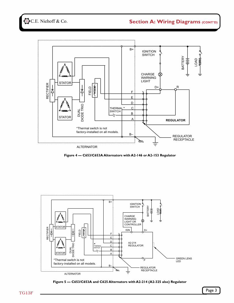
Figure 4 — C653/C653A Alternators with A2-146 or A2-153 Regulator
Figure 5 — C653/C653A and C625 Alternators with A2-214 (A2-325 also) Regulator
Section A: Wiring Diagrams (CONT’D)
*
*Thermal switch is not factory-installed on all models.
*
REGULATOR
*Thermal switch is not factory-installed on all models.

Page 4TG13F
SYMPTOM ACTION
TABLE 1 – System Conditions
Check: loose drive belt; low bat-tery state of charge.
Check: current load on system is greater than alternator can produce.
Check: defective wiring or poor ground path; low regulator setpoint.
Check: defective alternator or regulator.
Check: wrong regulator.
Check: high regulator setpoint.
Check: defective regulator.
Check: alternator.
Check: broken drive belt.
Check: battery voltage at alter-nator output terminal.
Check: defective alternator or regulator.
Check: lost residual magnetism in self-energizing alternator. Go to:
• Chart 1, page 5, for A2-146/ A2-153
• Chart 2, page 7, for A2-214 • Chart 4, page 10, for A2-325
Low Voltage Output
High Voltage Output
No Voltage Output
Preliminary Check-outCheck symptoms in Table 1 and correct if necessary.
Tools and Equipment for Job• Digital Multimeter (DMM)
• Ammeter (digital, inductive)
• Jumper wires
Identification RecordList the following for proper troubleshooting:
Alternator model number _________________________
Regulator model number ________________________
Setpoints listed on regulator _____________________
Section B: Basic Troubleshooting
Basic Troubleshooting1. Inspect charging system components for damage
Check connections at B– cable, B+ cable, and regulator harness. Also check connections at regulator terminal wiring from regulator to vehicle components. Repair or replace any damaged component before electrical troubleshooting.
2. Inspect vehicle battery connections Connections must be clean and tight.
3. Check drive belt Repair or replace as necessary.
4. Determine battery voltage and state of charge If batteries are discharged, recharge or replace batteries as necessary. Electrical system cannot be properly tested unless batteries are charged 95% or higher.
5. Connect meters to alternator Connect red lead of DMM to alternator B+ terminal and black lead to alternator B– terminal. Clamp inductive ammeter on B+ cable.
6. Operate vehicle Observe charge voltage. If charge voltage is above 32 volts, immediately shut down system. Electrical system damage may occur if charging system is allowed to operate at high voltage. Go to Table 1.
If voltage is at or below regulator setpoint, let charging system operate for several minutes to normalize operating temperature.
7. Observe charge volts and amps Charge voltage should increase and charge amps should decrease. If charge voltage does not increase within ten minutes, continue to next step.
8. Battery is considered fully charged if charge voltage is at regulator setpoint and charge amps remain at lowest value for 10 minutes.
9. If charging system is not performing properly, go to:
• Chart 1, page 5, for A2-146/A2-153
• Chart 3, page 8, for A2-214
• Chart 5, page 11, for A2-325
CAUTION
Failure to check for the following conditions will result in erroneous test results in the troubleshooting charts.
NOTICE
Page 5TG13F
Section C: A2-146/A2-153 Advanced Troubleshooting
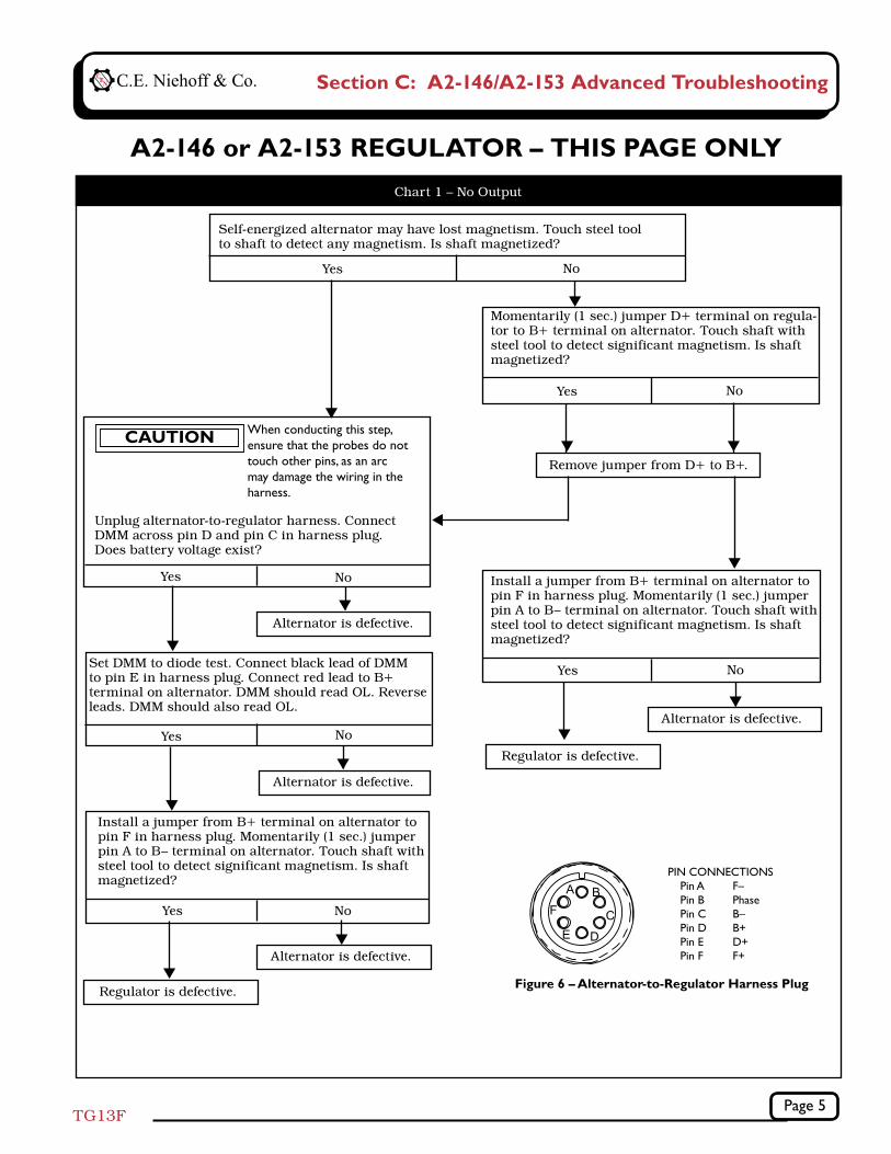
A2-146 or A2-153 REGULATOR – THIS PAGE ONLY
Self-energized alternator may have lost magnetism. Touch steel tool to shaft to detect any magnetism. Is shaft magnetized?
Momentarily (1 sec.) jumper D+ terminal on regula-tor to B+ terminal on alternator. Touch shaft with steel tool to detect significant magnetism. Is shaft magnetized?
Yes No
Yes No
Figure 6 – Alternator-to-Regulator Harness Plug
Chart 1 – No Output
Install a jumper from B+ terminal on alternator to pin F in harness plug. Momentarily (1 sec.) jumper pin A to B– terminal on alternator. Touch shaft with steel tool to detect significant magnetism. Is shaft magnetized?
Yes No
PIN CONNECTIONS Pin A F– Pin B Phase Pin C B– Pin D B+ Pin E D+ Pin F F+
Set DMM to diode test. Connect black lead of DMM to pin E in harness plug. Connect red lead to B+ terminal on alternator. DMM should read OL. Reverse leads. DMM should also read OL.
Unplug alternator-to-regulator harness. Connect DMM across pin D and pin C in harness plug. Does battery voltage exist?
Yes No
Alternator is defective.
Yes No
Alternator is defective.
Alternator is defective.
Regulator is defective.
Install a jumper from B+ terminal on alternator to pin F in harness plug. Momentarily (1 sec.) jumper pin A to B– terminal on alternator. Touch shaft with steel tool to detect significant magnetism. Is shaft magnetized?
Yes No
Alternator is defective.
Regulator is defective.
Remove jumper from D+ to B+.
When conducting this step, ensure that the probes do not touch other pins, as an arc may damage the wiring in the harness.
CAUTION
Page 6TG13F
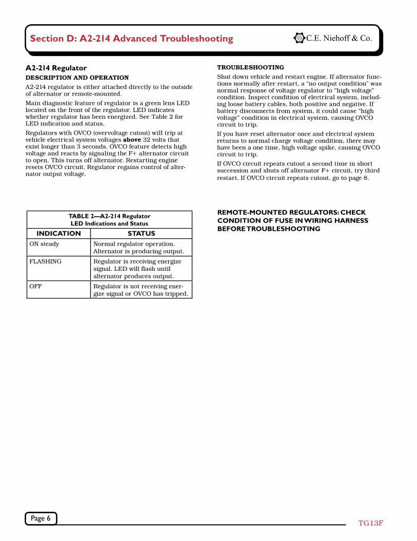
A2-214 Regulator DeSCrIptIOn AnD OperAtIOnA2-214 regulator is either attached directly to the outside of alternator or remote-mounted.
Main diagnostic feature of regulator is a green lens LED located on the front of the regulator. LED indicates whether regulator has been energized. See Table 2 for LED indication and status.
Regulators with OVCO (overvoltage cutout) will trip at vehicle electrical system voltages above 32 volts that exist longer than 3 seconds. OVCO feature detects high voltage and reacts by signaling the F+ alternator circuit to open. This turns off alternator. Restarting engine resets OVCO circuit. Regulator regains control of alter-nator output voltage.
trOUBLeSHOOtInGShut down vehicle and restart engine. If alternator func-tions normally after restart, a “no output condition” was normal response of voltage regulator to “high voltage” condition. Inspect condition of electrical system, includ-ing loose battery cables, both positive and negative. If battery disconnects from system, it could cause “high voltage” condition in electrical system, causing OVCO circuit to trip.
If you have reset alternator once and electrical system returns to normal charge voltage condition, there may have been a one time, high voltage spike, causing OVCO circuit to trip.
If OVCO circuit repeats cutout a second time in short succession and shuts off alternator F+ circuit, try third restart. If OVCO circuit repeats cutout, go to page 8.
REMOTE-MOUNTED REGULATORS: CHECK CONDITION OF FUSE IN WIRING HARNESS BEFORE TROUBLESHOOTING
TABLE 2—A2-214 Regulator LED Indications and Status
INDICATION STATUSON steady Normal regulator operation.
Alternator is producing output.
FLASHING Regulator is receiving energize signal. LED will flash until alternator produces output.
OFF Regulator is not receiving ener-gize signal or OVCO has tripped.
Section D: A2-214 Advanced Troubleshooting
Page 7TG13F
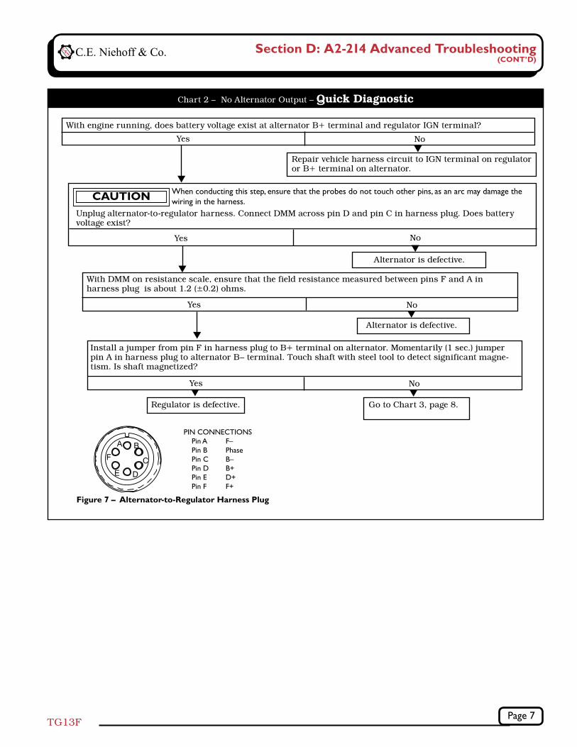
Chart 2 – No Alternator Output – Quick Diagnostic
Figure 7 – Alternator-to-Regulator Harness Plug
PIN CONNECTIONS Pin A F– Pin B Phase Pin C B– Pin D B+ Pin E D+ Pin F F+
With engine running, does battery voltage exist at alternator B+ terminal and regulator IGN terminal?
Yes No
Repair vehicle harness circuit to IGN terminal on regulator or B+ terminal on alternator.
Yes No
Alternator is defective.
With DMM on resistance scale, ensure that the field resistance measured between pins F and A in harness plug is about 1.2 (±0.2) ohms.
Yes No
Alternator is defective.
Install a jumper from pin F in harness plug to B+ terminal on alternator. Momentarily (1 sec.) jumper pin A in harness plug to alternator B– terminal. Touch shaft with steel tool to detect significant magne-tism. Is shaft magnetized?
Yes No
Go to Chart 3, page 8.
Regulator is defective.
Unplug alternator-to-regulator harness. Connect DMM across pin D and pin C in harness plug. Does battery voltage exist?
When conducting this step, ensure that the probes do not touch other pins, as an arc may damage the wiring in the harness.CAUTION
Section D: A2-214 Advanced Troubleshooting (CONT’D)
Page 8TG13F
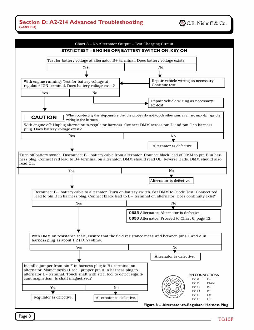
Chart 3 – No Alternator Output – Test Charging Circuit
STATIC TEST – ENGINE OFF, BATTERY SWITCH ON, KEY ON
PIN CONNECTIONS Pin A F– Pin B Phase Pin C B– Pin D B+ Pin E D+ Pin F F+
Figure 8 – Alternator-to-Regulator Harness Plug
Test for battery voltage at alternator B+ terminal. Does battery voltage exist?
Yes No
Repair vehicle wiring as necessary. Continue test.
With engine running: Test for battery voltage at regulator IGN terminal. Does battery voltage exist?
Yes No
Repair vehicle wiring as necessary. Re-test.
With engine off: Unplug alternator-to-regulator harness. Connect DMM across pin D and pin C in harness plug. Does battery voltage exist?
Yes No
Alternator is defective.
Install a jumper from pin F in harness plug to B+ terminal on alternator. Momentarily (1 sec.) jumper pin A in harness plug to alternator B– terminal. Touch shaft with steel tool to detect signifi-cant magnetism. Is shaft magnetized?
Yes No
Alternator is defective.
Turn off battery switch. Disconnect B+ battery cable from alternator. Connect black lead of DMM to pin E in har-ness plug. Connect red lead to B+ terminal on alternator. DMM should read OL. Reverse leads. DMM should also read OL.
Yes No
Alternator is defective.
Reconnect B+ battery cable to alternator. Turn on battery switch. Set DMM to Diode Test. Connect red lead to pin B in harness plug. Connect black lead to B+ terminal on alternator. Does continuity exist?
Yes No
Regulator is defective.
With DMM on resistance scale, ensure that the field resistance measured between pins F and A in harness plug is about 1.2 (±0.2) ohms.
Yes No
Alternator is defective.
When conducting this step, ensure that the probes do not touch other pins, as an arc may damage the wiring in the harness.CAUTION
C625 Alternator: Alternator is defective.
C653 Alternator: Proceed to Chart 6, page 12.
Section D: A2-214 Advanced Troubleshooting(CONT’D)
Page 9TG13F
Section E: C653 w/A2-325 Advanced Troubleshooting
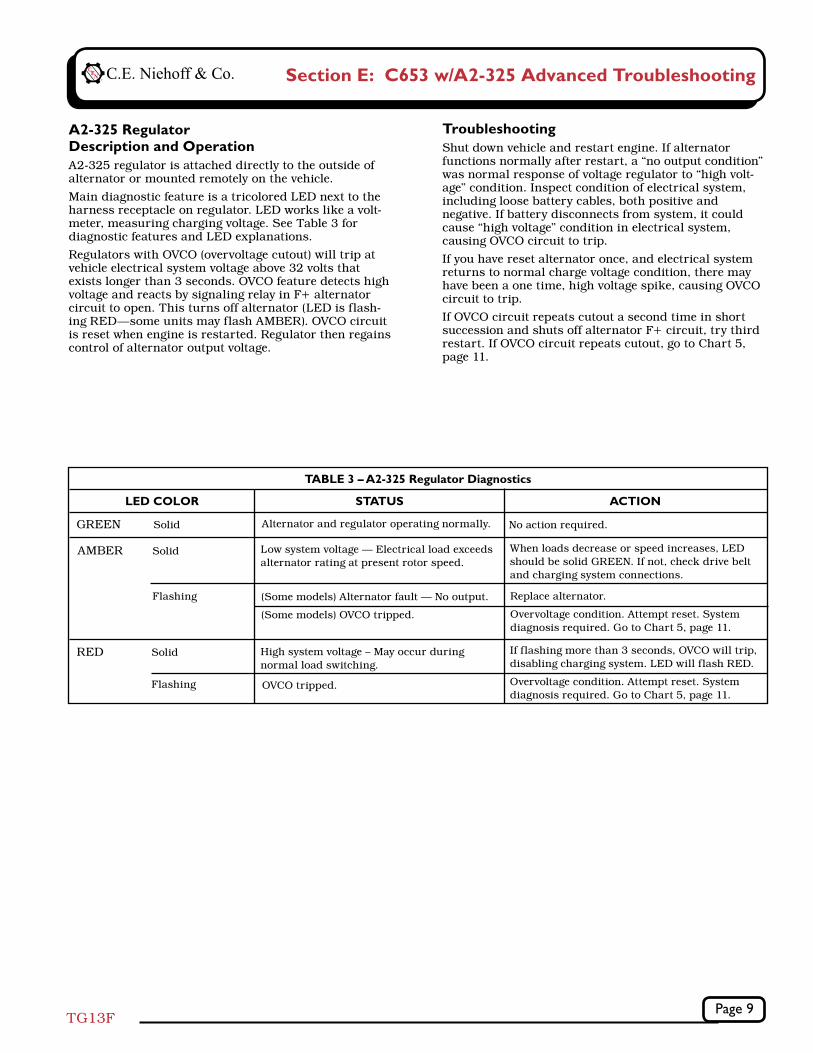
A2-325 Regulator Description and OperationA2-325 regulator is attached directly to the outside of alternator or mounted remotely on the vehicle.
Main diagnostic feature is a tricolored LED next to the harness receptacle on regulator. LED works like a volt-meter, measuring charging voltage. See Table 3 for diagnostic features and LED explanations.
Regulators with OVCO (overvoltage cutout) will trip at vehicle electrical system voltage above 32 volts that exists longer than 3 seconds. OVCO feature detects high voltage and reacts by signaling relay in F+ alternator circuit to open. This turns off alternator (LED is flash-ing RED—some units may flash AMBER). OVCO circuit is reset when engine is restarted. Regulator then regains control of alternator output voltage.
LED COLOR STATUS
TABLE 3 – A2-325 Regulator Diagnostics
Alternator and regulator operating normally.GREEN Solid
Low system voltage — Electrical load exceeds alternator rating at present rotor speed.
ACTION
No action required.
When loads decrease or speed increases, LED should be solid GREEN. If not, check drive belt and charging system connections.
AMBER Solid
High system voltage – May occur during normal load switching.
If flashing more than 3 seconds, OVCO will trip, disabling charging system. LED will flash RED.
Overvoltage condition. Attempt reset. System diagnosis required. Go to Chart 5, page 11.
RED Solid
(Some models) Alternator fault — No output.
(Some models) OVCO tripped.
Flashing
Flashing OVCO tripped.
TroubleshootingShut down vehicle and restart engine. If alternator functions normally after restart, a “no output condition” was normal response of voltage regulator to “high volt-age” condition. Inspect condition of electrical system, including loose battery cables, both positive and negative. If battery disconnects from system, it could cause “high voltage” condition in electrical system, causing OVCO circuit to trip.
If you have reset alternator once, and electrical system returns to normal charge voltage condition, there may have been a one time, high voltage spike, causing OVCO circuit to trip.
If OVCO circuit repeats cutout a second time in short succession and shuts off alternator F+ circuit, try third restart. If OVCO circuit repeats cutout, go to Chart 5, page 11.
Replace alternator.
Overvoltage condition. Attempt reset. System diagnosis required. Go to Chart 5, page 11.
Page 10TG13F
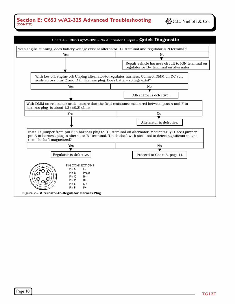
Figure 9 – Alternator-to-Regulator Harness Plug
PIN CONNECTIONS Pin A F– Pin B Phase Pin C B– Pin D B+ Pin E D+ Pin F F+
Chart 4 – C653 w/A2-325 – No Alternator Output – Quick Diagnostic
With engine running, does battery voltage exist at alternator B+ terminal and regulator IGN terminal?
Yes No
Repair vehicle harness circuit to IGN terminal on regulator or B+ terminal on alternator.
With key off, engine off: Unplug alternator-to-regulator harness. Connect DMM on DC volt scale across pins C and D in harness plug. Does battery voltage exist?
Yes No
Alternator is defective.
With DMM on resistance scale, ensure that the field resistance measured between pins A and F in harness plug is about 1.2 (±0.2) ohms.
Yes No
Alternator is defective.
Install a jumper from pin F in harness plug to B+ terminal on alternator. Momentarily (1 sec.) jumper pin A in harness plug to alternator B– terminal. Touch shaft with steel tool to detect significant magne-tism. Is shaft magnetized?
Yes No
Proceed to Chart 5, page 11.
Regulator is defective.
Section E: C653 w/A2-325 Advanced Troubleshooting(CONT’D)
Page 11TG13F
Section E: C653 w/A2-325 Advanced Troubleshooting (CONT’D)
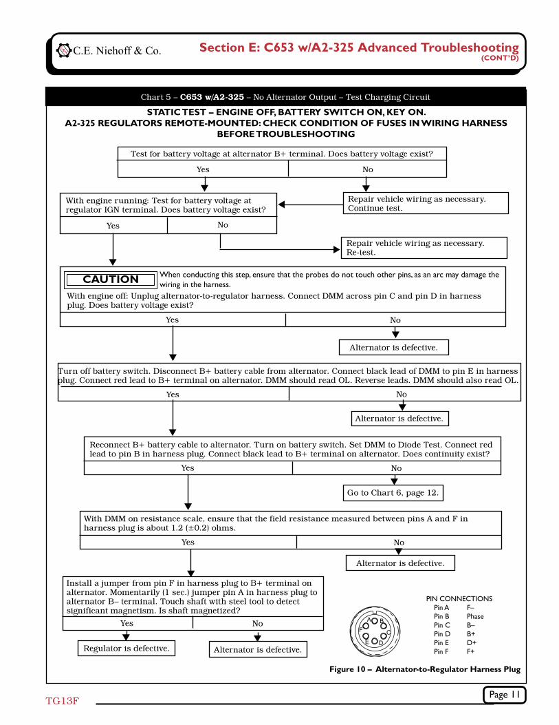
Chart 5 – C653 w/A2-325 – No Alternator Output – Test Charging Circuit
STATIC TEST – ENGINE OFF, BATTERY SWITCH ON, KEY ON.A2-325 REGULATORS REMOTE-MOUNTED: CHECK CONDITION OF FUSES IN WIRING HARNESS
BEFORE TROUBLESHOOTING
Figure 10 – Alternator-to-Regulator Harness Plug
PIN CONNECTIONS Pin A F– Pin B Phase Pin C B– Pin D B+ Pin E D+ Pin F F+
Test for battery voltage at alternator B+ terminal. Does battery voltage exist?
Yes No
Repair vehicle wiring as necessary. Continue test.
With engine running: Test for battery voltage at regulator IGN terminal. Does battery voltage exist?
Yes No
Repair vehicle wiring as necessary. Re-test.
With engine off: Unplug alternator-to-regulator harness. Connect DMM across pin C and pin D in harness plug. Does battery voltage exist?
Yes No
Alternator is defective.
Install a jumper from pin F in harness plug to B+ terminal on alternator. Momentarily (1 sec.) jumper pin A in harness plug to alternator B– terminal. Touch shaft with steel tool to detect significant magnetism. Is shaft magnetized?
Yes No
Alternator is defective.
Turn off battery switch. Disconnect B+ battery cable from alternator. Connect black lead of DMM to pin E in harness plug. Connect red lead to B+ terminal on alternator. DMM should read OL. Reverse leads. DMM should also read OL.
Yes No
Alternator is defective.
Reconnect B+ battery cable to alternator. Turn on battery switch. Set DMM to Diode Test. Connect red lead to pin B in harness plug. Connect black lead to B+ terminal on alternator. Does continuity exist?
Yes No
Go to Chart 6, page 12.
Regulator is defective.
With DMM on resistance scale, ensure that the field resistance measured between pins A and F in harness plug is about 1.2 (±0.2) ohms.
Yes No
Alternator is defective.
When conducting this step, ensure that the probes do not touch other pins, as an arc may damage the wiring in the harness.CAUTION
Page 12TG13F
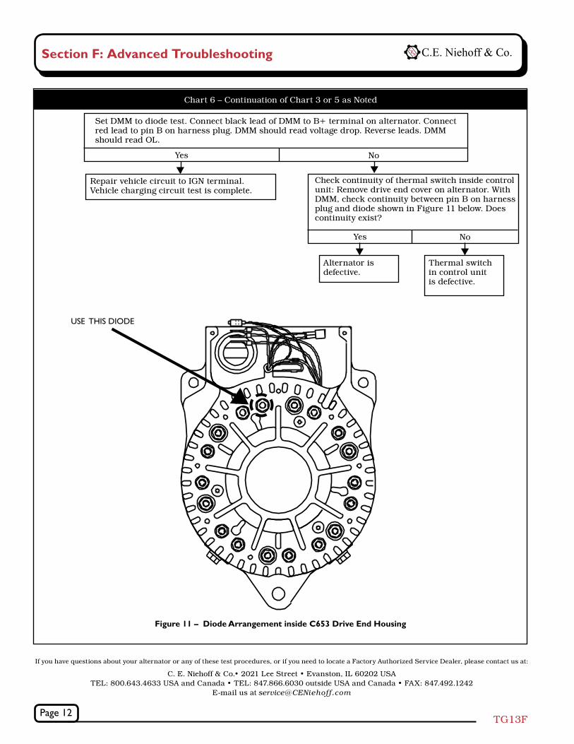
Repair vehicle circuit to IGN terminal. Vehicle charging circuit test is complete.
Set DMM to diode test. Connect black lead of DMM to B+ terminal on alternator. Connect red lead to pin B on harness plug. DMM should read voltage drop. Reverse leads. DMM should read OL.
Check continuity of thermal switch inside control unit: Remove drive end cover on alternator. With DMM, check continuity between pin B on harness plug and diode shown in Figure 11 below. Does continuity exist?
Yes No
Yes No
Alternator is defective.
Thermal switch in control unit is defective.
Figure 11 – Diode Arrangement inside C653 Drive End Housing
USE THIS DIODE
Chart 6 – Continuation of Chart 3 or 5 as Noted
If you have questions about your alternator or any of these test procedures, or if you need to locate a Factory Authorized Service Dealer, please contact us at:
C. E. Niehoff & Co.• 2021 Lee Street • Evanston, IL 60202 USA TEL: 800.643.4633 USA and Canada • TEL: 847.866.6030 outside USA and Canada • FAX: 847.492.1242
E-mail us at [email protected]
Section F: Advanced Troubleshooting