cd horizon legacy - mt ortho · cd horizon ® legacy ... the force vectors a set screw normally...
TRANSCRIPT

CD HORIZON® LEGACY™
Spinal System – Degenerative Surgical Techniqueas described by:
John R. Johnson, MDSteven D. Glassman, MDRolando M. Puno, MDJohn R. Dimar, II, MDMitchell J. Campbell, MDLeatherman Spine CenterLouisville, Kentucky
George Frey, MD Colorado Comprehensive Spine InstituteEnglewood, Colorado
Thomas Kiaer, MDRigshospitaletCopenhagen, Denmark
Pierre Lascombes, MDCHU de BraboisNancy, France
Edward P. Abraham, MD, FRCS (C)Saint John Regional HospitalSaint John, Canada
Stephen J. Lewis, MD, MSc, FRCS (C)Toronto Western HospitalToronto, Canada
Daniele Fabris Monterumici, MDClinica OrtopedicaTraumatologicaUniversita di Padova, Italy

1CD HORIZON® LEGACY™ Spinal System Degenerative Technique
Preface . . . . . . . . . . . . . . . . . . . . . . . . . . . . . . . . . . . . . . . . . . . . . . . . . . . . . . . . . . . . . . . . . . . . . . . . . . . . . 2
Implants. . . . . . . . . . . . . . . . . . . . . . . . . . . . . . . . . . . . . . . . . . . . . . . . . . . . . . . . . . . . . . . . . . . . . . . . . . . . . 3
Instruments . . . . . . . . . . . . . . . . . . . . . . . . . . . . . . . . . . . . . . . . . . . . . . . . . . . . . . . . . . . . . . . . . . . . . . . . . 4
Surgical Technique
Pedicle Preparation . . . . . . . . . . . . . . . . . . . . . . . . . . . . . . . . . . . . . . . . . . . . . . . . . . . . . . . . . . . 8
Multi Axial Screw Insertion . . . . . . . . . . . . . . . . . . . . . . . . . . . . . . . . . . . . . . . . . . . . . . . . . . . . 12
Rod Insertion. . . . . . . . . . . . . . . . . . . . . . . . . . . . . . . . . . . . . . . . . . . . . . . . . . . . . . . . . . . . . . . . . 14
Rod Reduction Options . . . . . . . . . . . . . . . . . . . . . . . . . . . . . . . . . . . . . . . . . . . . . . . . . . . . . . . 16
Compression and Distraction . . . . . . . . . . . . . . . . . . . . . . . . . . . . . . . . . . . . . . . . . . . . . . . . . . 18
Final Tightening . . . . . . . . . . . . . . . . . . . . . . . . . . . . . . . . . . . . . . . . . . . . . . . . . . . . . . . . . . . . . . 19
Graft Placement. . . . . . . . . . . . . . . . . . . . . . . . . . . . . . . . . . . . . . . . . . . . . . . . . . . . . . . . . . . . . . 21
X10 CROSSLINK™ Plate Placement. . . . . . . . . . . . . . . . . . . . . . . . . . . . . . . . . . . . . . . . . . . . 22
Postoperative Care and Mobilization . . . . . . . . . . . . . . . . . . . . . . . . . . . . . . . . . . . . . . . . . . 26
Product Ordering Information. . . . . . . . . . . . . . . . . . . . . . . . . . . . . . . . . . . . . . . . . . . . . . . . . . . . . . . . 28
Important Product Information. . . . . . . . . . . . . . . . . . . . . . . . . . . . . . . . . . . . . . . . . . . . . . . . . . . . . . . 33
TABLE OF CONTENTS

2 CD HORIZON® LEGACY™ Spinal SystemDegenerative Technique
Over the past 10 years there has been a continuous evolution in the surgical application of pedicle screw fi xation. Meeting the needs of advancing surgical techniques has required systems that are adaptable, reliable, and user-friendly. The CD HORIZON® Multi Axial Screw Spinal System has become one of the world’s most popular pedicle screw instrumentation by continuing to evolve and address these developmental goals. Building on this success, Medtronic Sofamor Danek introduces the next generation in the CD HORIZON® Spinal System lineage, the CD HORIZON® LEGACY™ Spinal System.
The CD HORIZON® LEGACY™ Spinal System is a familiar top-loading multi axial screw system with an enhanced locking mechanism, a lower functional profi le, and an ergonomically designed instrument set. The system has also been designed for treatment of degenerative disease, deformity, and trauma indications.
A primary enhancement of the CD HORIZON® LEGACY™ Spinal System is a unique reverse-angle thread locking mechanism. This locking mechanism preserves the ease of top-loading set screw introduction, while helping to eliminate the diffi culties of cross-threading. This patented design, known as G4 Technology, also improves the ease and security of fi nal tightening. An additional improvement is a reduction in the multi axial screw “footprint.” This modifi cation diminishes the functional profi le of the screw and limits the problems of facet impingement. Beyond these advances in implant design, the instrument set has been signifi cantly re-engineered and improved.
In addition to the technical advances, an important design focus of the CD HORIZON® LEGACY™ Spinal System was to accommodate the specialized needs of the hospital and OR staff. Important factors include a broad range of surgical capabilities within a single system and the availability of modules for treatment of deformity and other specialty needs. Other alterations, such as color-coding by screw size, serve to limit the complexity of the system for the OR technician. Overall, the CD HORIZON® LEGACY™ Spinal System represents an advancement in the development and refi nement of pedicle screw instrumentation.
PREFACE

3CD HORIZON® LEGACY™ Spinal System Degenerative Technique
Titanium screw head internal washers are color-coded by screw diameter.
4.0mm 4.5mm 5.0mm 5.5mm 6.5mm 7.5mm 8.5mmCD HORIZON® LEGACY™
Multi Axial Screw
Color-Coding Reference
NOTE: Color-coding available in titanium only.
5.5mm Rod CD HORIZON® System Precut Contoured RodNOTE: Available in titanium only.
Multi Axial Screws/Rods
G4 Technology is the fourth generation closure technology for CD HORIZON® instrumentation. The set screw has been designed to thread easier and hold stronger. The reverse-angle thread locking mechanism reverses the force vectors a set screw normally exerts on the side walls of implants during final tightening.
IMPLANTS
Patented reverse-angle thread technology offers a lower profile implant with no sacrifice in performance
Improves the ease of insertion and security of final tightening
Reduction in the “footprint” preserves the superior facet joint, lowers the construct’s overall profile, and enhances the multi axial capabilities
Preserves the ease of top-loading set screw introduction, yet eliminates difficulties of cross-threading
Set screws are available in break-off and non break-off
Provides optimal patient matching with seven screw diameters
Allows more room for bone graft
4 CD HORIZON® LEGACY™ Spinal SystemDegenerative Technique
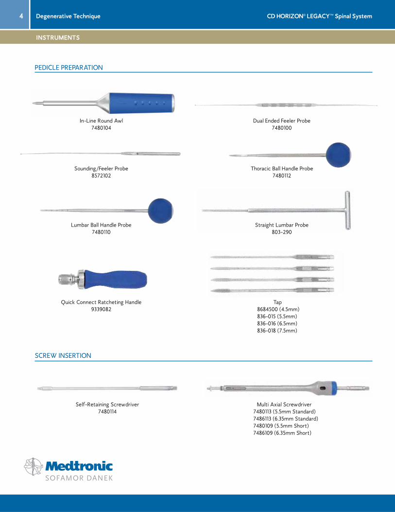
Dual Ended Feeler Probe7480100
Self-Retaining Screwdriver7480114
Quick Connect Ratcheting Handle9339082
Sounding/Feeler Probe8572102
Multi Axial Screwdriver 7480113 (5.5mm Standard) 7486113 (6.35mm Standard) 7480109 (5.5mm Short) 7486109 (6.35mm Short)
In-Line Round Awl7480104
Lumbar Ball Handle Probe7480110
Thoracic Ball Handle Probe7480112
Tap 8684500 (4.5mm) 836-015 (5.5mm) 836-016 (6.5mm) 836-018 (7.5mm)
Straight Lumbar Probe803-290
INSTRUMENTS
PEDICLE PREPARATION
SCREW INSERTION

5CD HORIZON® LEGACY™ Spinal System Degenerative Technique
Rod Inserter 7480126 (5.5mm) 7486126 (6.35mm)
Forceps Rocker 7480142 (5.5mm) 7486142 (6.35mm)
French Bender7480162
Rod Template808-575
Beale Rod Reducer 7480134 (5.5mm) 7486134 (6.35mm)
Provisional Driver7480131
Rod Gripper 7480175 (5.5mm) 7486175 (6.35mm)
Dual Ended Plug Starter7480122
ROD REDUCTION
ROD INSERTION
INSTRUMENTS

6 CD HORIZON® LEGACY™ Spinal SystemDegenerative Technique
Parallel Compressor, Small7480165
Parallel Distractor7480170
Counter Torque 7480150 (5.5mm) 7486150 (6.35mm)
Self-Retaining Break-Off Driver7480144
T27 Obturator7480154
Additional Instruments
Non Break-Off Plug Starter7480156
T27 - Quick Connect7480147
Torque-Limiting Driver 7480146 (5.5mm) 7486146 (6.35mm)
TORX 25 Shaft 815-518
3.0mm Hex Driver8110530
COMPRESSION AND DISTRACTION
ADDITIONAL INSTRUMENTS
INSTRUMENTS
FINAL TIGHTENING

7CD HORIZON® LEGACY™ Spinal System Degenerative Technique
Counter Torque8110540
3.0mm Hex Head Shaft, Removal Driver 8110530
7/32” Torque-Limiting Set Screwdriver8110535
Forceps Plate Holder8110510 (optional)
Plate Benders8110525
45° In Line Plate Holder8110511
Measuring Credit Card 8110501 (5.5mm) 7486175 (6.35mm)
Measuring Caliper8110502
X10 CROSSLINK™ MULTI-SPAN® Plate X10 CROSSLINK™ Fixed Plate
Implant Positioners808-545 (optional)
INSTRUMENTS
X10 CROSSLINK™ PLATE IMPLANTS AND INSTRUMENTS
8 CD HORIZON® LEGACY™ Spinal SystemDegenerative Technique
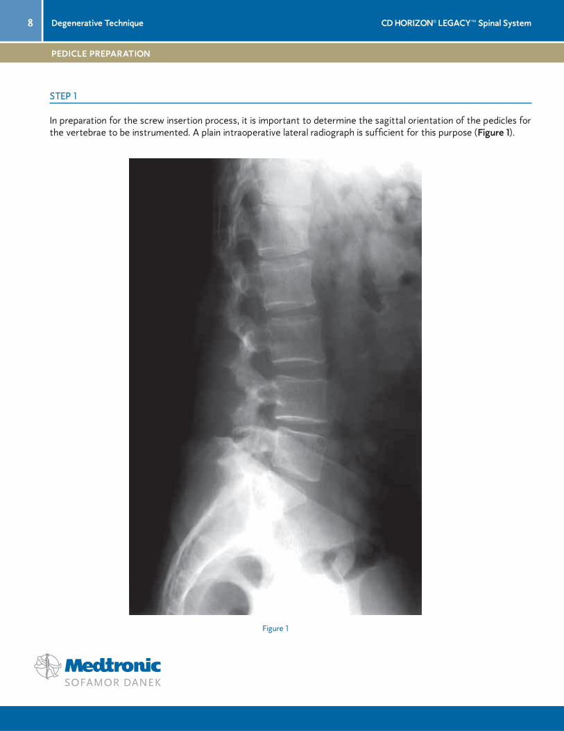
Figure 1
In preparation for the screw insertion process, it is important to determine the sagittal orientation of the pedicles for the vertebrae to be instrumented. A plain intraoperative lateral radiograph is suffi cient for this purpose (Figure 1).
STEP 1
PEDICLE PREPARATION

9CD HORIZON® LEGACY™ Spinal System Degenerative Technique
Identify the appropriate anatomical landmarks for creating the entry points of the pilot holes for screw insertion (Figures 2a and 2b).
Figure 2a
Figure 2b
PEDICLE PREPARATION (CONTINUED)
STEP 1

10 CD HORIZON® LEGACY™ Spinal SystemDegenerative Technique
Pilot holes are created with a sharp awl or burr, depending on surgeon preference (Figure 3), and then followed by either a Thoracic or Lumbar Ball Handle Probe (Figure 4) or a Straight Lumbar Probe.
Figure 3 Figure 4
“At this time a feeler probe may be used to follow the pilot holes and palpate for any perforations in the pedicle walls.”
STEP 1
PEDICLE PREPARATION (CONTINUED)
11CD HORIZON® LEGACY™ Spinal System Degenerative Technique
PEDICLE PREPARATION (CONTINUED)
STEP 1
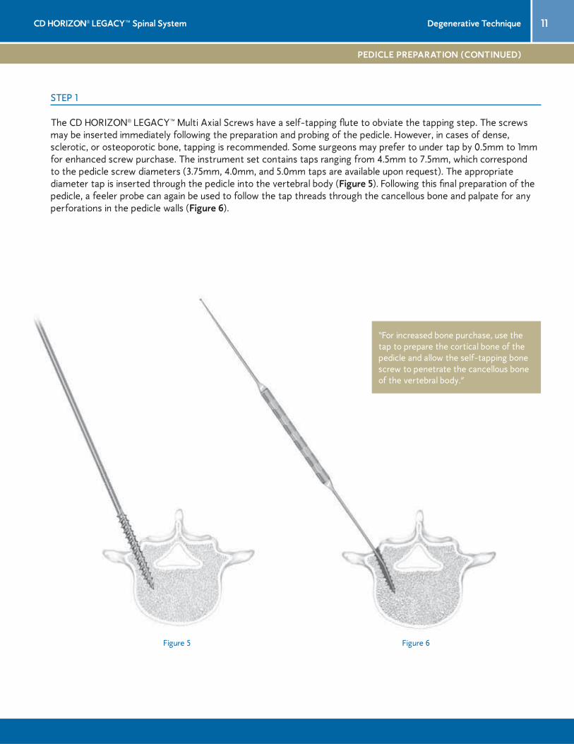
The CD HORIZON® LEGACY™ Multi Axial Screws have a self-tapping fl ute to obviate the tapping step. The screws may be inserted immediately following the preparation and probing of the pedicle. However, in cases of dense, sclerotic, or osteoporotic bone, tapping is recommended. Some surgeons may prefer to under tap by 0.5mm to 1mm for enhanced screw purchase. The instrument set contains taps ranging from 4.5mm to 7.5mm, which correspond to the pedicle screw diameters (3.75mm, 4.0mm, and 5.0mm taps are available upon request). The appropriate diameter tap is inserted through the pedicle into the vertebral body (Figure 5). Following this fi nal preparation of the pedicle, a feeler probe can again be used to follow the tap threads through the cancellous bone and palpate for any perforations in the pedicle walls (Figure 6).
Figure 5 Figure 6
“For increased bone purchase, use the tap to prepare the cortical bone of the pedicle and allow the self-tapping bone screw to penetrate the cancellous bone of the vertebral body.”
12 CD HORIZON® LEGACY™ Spinal SystemDegenerative Technique
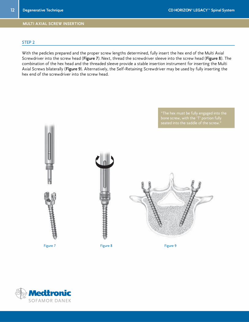
With the pedicles prepared and the proper screw lengths determined, fully insert the hex end of the Multi Axial Screwdriver into the screw head (Figure 7). Next, thread the screwdriver sleeve into the screw head (Figure 8). The combination of the hex head and the threaded sleeve provide a stable insertion instrument for inserting the Multi Axial Screws bilaterally (Figure 9). Alternatively, the Self-Retaining Screwdriver may be used by fully inserting the hex end of the screwdriver into the screw head.
Figure 7 Figure 9Figure 8
STEP 2
MULTI AXIAL SCREW INSERTION
“The hex must be fully engaged into the bone screw, with the ‘T’ portion fully seated into the saddle of the screw.”

13CD HORIZON® LEGACY™ Spinal System Degenerative Technique
MULTI AXIAL INSERTION (CONTINUED)
STEP 2
Intraoperative posteroanterior and lateral plain radiographs are taken to evaluate the position of the screws in two planes (Figures 10a and 10b). Intraoperative EMG monitoring can be used if available. When fully inserted, the screws should extend 50 to 80% into the vertebral body and be parallel to the superior endplate. For sacral fi xation, especially when the bone is osteopenic, bicortical purchase may be utilized. Some surgeons also suggest targeting screws toward the “tri-cortical point” (the convergence of the S1 endplate to the anterior cortex), which provides the best fi xation for the S1 pedicle screw. Once the screw is inserted, the instrument sleeve is unscrewed and the screwdriver is disengaged from the screw.
Figure 10a
“The reduced screw head footprint has four immediately noticeable benefi ts: enhanced multi axial capability, lower overall construct profi le, the ability to preserve the superior facet, and better access for bone graft placement.”
Figure 10b
14 CD HORIZON® LEGACY™ Spinal SystemDegenerative Technique
Figure 11
STEP 3
ROD INSERTION
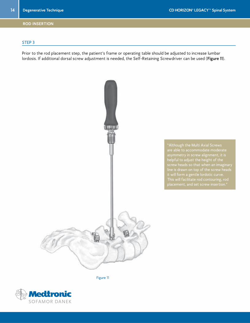
Prior to the rod placement step, the patient’s frame or operating table should be adjusted to increase lumbar lordosis. If additional dorsal screw adjustment is needed, the Self-Retaining Screwdriver can be used (Figure 11).
“Although the Multi Axial Screws are able to accommodate moderate asymmetry in screw alignment, it is helpful to adjust the height of the screw heads so that when an imaginary line is drawn on top of the screw heads it will form a gentle lordotic curve. This will facilitate rod contouring, rod placement, and set screw insertion.”

15CD HORIZON® LEGACY™ Spinal System Degenerative Technique
Figure 13Figure 12
Figure 14
Next, the rod is placed into the top-loading screws beginning from either the cephalad or caudad direction using either the Rod Inserter (Figure 12) or the Rod Gripper (Figure 13). With the rod lying in the bottom of the screw heads, the Break-Off Set Screws (hereafter referred to as “plugs”) may be inserted into the implants using the plug starter (Figure 14).
“Multiple plugs can be loaded into the plug starter for intraoperative effi ciency.”
ROD INSERTION (CONTINUED)
STEP 3

16 CD HORIZON® LEGACY™ Spinal SystemDegenerative Technique
STEP 4
ROD REDUCTION OPTIONS
If the rod is not fully seated into the bottom of the screw head, the Beale Rod Reducer or the Forceps Rocker can be used to fully seat the rod and simplify the plug insertion process. NOTE: Care should be taken with any rod reduction maneuver. Improper instrument use may dislodge the implants or damage the bony anatomy.
The Beale Rod Reducer is the preferred method for reduction when the rod is lying even to the top of the implant head. To use the rod reducer, position the reducer so that the handles are parallel to the rod and grasp the screw head from above. The reducer handles are slowly compressed allowing the sleeve to slide down and seat the rod (Figure 15). The plug starter or Provisional Driver is then inserted through the rod reducer plug tube to insert the plug into the head of the pedicle screw (Figure 16).
Figure 16
Figure 15
17CD HORIZON® LEGACY™ Spinal System Degenerative Technique
ROD REDUCTION (CONTINUED)
STEP 4
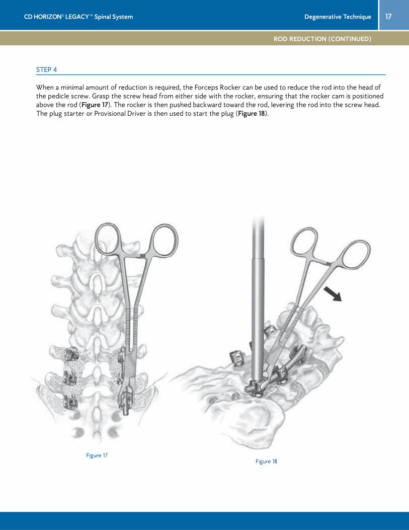
When a minimal amount of reduction is required, the Forceps Rocker can be used to reduce the rod into the head of the pedicle screw. Grasp the screw head from either side with the rocker, ensuring that the rocker cam is positioned above the rod (Figure 17). The rocker is then pushed backward toward the rod, levering the rod into the screw head. The plug starter or Provisional Driver is then used to start the plug (Figure 18).
Figure 17Figure 18

18 CD HORIZON® LEGACY™ Spinal SystemDegenerative Technique
If either compression or distraction is needed, it should be performed at this time. In either maneuver, the plug on one side of the motion segment should be provisionally tightened, with the plug loose in the implant to be compressed or distracted. Compression or distraction will occur against the provisionally tightened implant.
The Provisional Driver may be used to temporarily lock and secure the rod and implant construct. Usually, temporary fi xation of the implant may be performed numerous times without damage to either the plug or the implant threads. However, if the plug has been cross-threaded, it must be replaced.
Care should be taken with all plugs to ensure that the feet of either the compressor or the distractor are placed securely against the implant body and not against the plug (Figure 19). Failure to do this may result in slippage of the implant or premature breaking of the plug. It is preferred that compression be released just prior to the plug being broken off or fi nal tightened. This technique will help ensure that the implant head and rod are normalized to one another and thus allow for the rod to be fully seated in the implant head during the fi nal tightening step. Once satisfactory compression or distraction has been achieved, fi nal tightening may be performed.
Figure 19
STEP 5
COMPRESSION AND DISTRACTION
“It is highly recommended that the plug not be broken off or fi nal tightened under compression.”

19CD HORIZON® LEGACY™ Spinal System Degenerative Technique
FINAL TIGHTENING
STEP 6
When all implants are securely in place, fi nal tightening and breakoff of the plug head is done. Insert the Self-Retaining Break-Off Driver into the cannulated portion of the Counter Torque, which should be positioned over the implant and rod. The t-handle on the driver provides adequate leverage for the break off of the plug head. The handle of the Counter Torque device should be held fi rmly to prevent torquing of the construct while the plug is secured and sheared off (Figure 20).
Figure 20
“A slight rostral/caudal movement of the Counter Torque during set screw tightening will adjust the Multi Axial Screw saddle squarely to the rod and should simplify fi nal tightening and breakoff.”
“Prior to fi nal tightening, ensure that the distance between the screw heads is adequate to place a X10 CROSSLINK™ Plate in the upper and lower one-third of the construct to increase construct rigidity.”

20 CD HORIZON® LEGACY™ Spinal SystemDegenerative Technique
STEP 6
FINAL TIGHTENING (CONTINUED)
Figure 21 Figure 22
After the plug head has been sheared off, it will be retained within the cannulated shaft of the Self-Retaining Break-Off Driver. Each additional plug can then be sequentially secured and sheared off, while the sheared pieces are retained (Figure 21). At any time following set screw breakoff, the T27 Obturator may be inserted into the cannulated shaft of the Self-Retaining Break-Off Driver to release the broken-off sections of the plug’s heads which have been retained in the driver (Figure 22).
21CD HORIZON® LEGACY™ Spinal System Degenerative Technique
GRAFT PLACEMENT
STEP 7
Figure 23
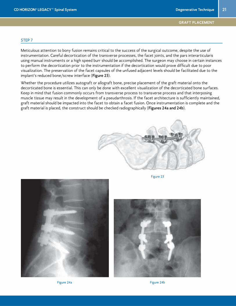
Meticulous attention to bony fusion remains critical to the success of the surgical outcome, despite the use of instrumentation. Careful decortication of the transverse processes, the facet joints, and the pars interarticularis using manual instruments or a high speed burr should be accomplished. The surgeon may choose in certain instances to perform the decortication prior to the instrumentation if the decortication would prove diffi cult due to poor visualization. The preservation of the facet capsules of the unfused adjacent levels should be facilitated due to the implant’s reduced bone/screw interface (Figure 23).
Whether the procedure utilizes autograft or allograft bone, precise placement of the graft material onto the decorticated bone is essential. This can only be done with excellent visualization of the decorticated bone surfaces. Keep in mind that fusion commonly occurs from transverse process to transverse process and that interposing muscle tissue may result in the development of a pseudarthrosis. If the facet architecture is suffi ciently maintained, graft material should be impacted into the facet to obtain a facet fusion. Once instrumentation is complete and the graft material is placed, the construct should be checked radiographically (Figures 24a and 24b).
Figure 24a Figure 24b

22 CD HORIZON® LEGACY™ Spinal SystemDegenerative Technique
Figure 25 Figure 26
X10 CROSSLINK™ Plates should be used to signifi cantly increase the torsional stability of a construct. Longer constructs may necessitate placement of an X10 CROSSLINK™ Plate at each end to increase construct rigidity. Two measuring devices are available to determine the proper length X10 CROSSLINK™ Plate to use: the Measuring Credit Card (Figure 25) and the Measuring Caliper (Figure 26).
Prior to plate placement, ensure that the X10 CROSSLINK™ Plate Set Screws are backed out to prevent binding during placement onto the rods of the construct. If the set screw is backed out too far, it will disengage from the plate but it can easily be reinserted.
STEP 8
X10 CROSSLINK™ PLATE PLACEMENT

23CD HORIZON® LEGACY™ Spinal System Degenerative Technique
The surgeon may choose one of several X10 CROSSLINK™ Plate placement options.
In Line Plate Holder Method
The midline nut is provisionally tightened to gain control of the multi-span device during placement. With the use of the In Line Plate Holder, the plate is selected, gripped and positioned to capture the far rod. Following placement of the plate onto one rod, tighten the set screw using the 7/32” Torque-Limiting Set Screwdriver until it is fi rmly attached to the rod (Figure 27). Next, loosen the midline nut to appreciate the multi axial fl exibility of the plate and seat the opposite end onto the other rod, followed by fi nal tightening of the Break-Off Set Screws to 60 in-lbs. Finally, tighten the midline nut to 80 in-lbs, remembering that the midline nut is NOT a Break-Off Set Screw (Figure 28).
Figure 27 Figure 28
X10 CROSSLINK™ PLATE PLACEMENT (CONTINUED)
STEP 8

24 CD HORIZON® LEGACY™ Spinal SystemDegenerative Technique
STEP 8
X10 CROSSLINK™ PLATE PLACEMENT (CONTINUED)
Implant Positioner Method
With the use of the Implant Positioners, the appropriate X10 CROSSLINK™ MULTI-SPAN® Plate is selected and gripped (Figure 29). Ensure that both Implant Positioners fi t securely onto both rod set screws.
The Implant Positioners can be used to sequentially articulate the X10 CROSSLINK™ Plate around the rod (Figure 29). If the plate cannot be precisely seated against the rod, the set screw is still too prominently extended into the ventral opening. Keep the plate in the wound and abutting against the rod. By rotating the implant positioners, the set screw can be manipulated and slightly backed out, allowing the rod to fully seat in the ventral opening. Once precise contact has been achieved between the plate and the rod, the implant positioners can be used to provisionally tighten the X10 CROSSLINK™ Plate to the rod. The same process is carried out for the other side of the plate. Both halves of the plate should precisely articulate with the rod before fi nal tightening and set screw breakoff (Figure 30).
Remove the Implant Positioners and provisionally tighten the midline nut using the 7/32” Torque-Limiting Set Screwdriver. A Counter Torque may be placed on the X10 CROSSLINK™ MULTI-SPAN® Plate to minimize torque transfer to the construct during fi nal tightening. The screwdriver shaft is introduced through the Counter Torque. The set screws are sheared off using the screwdriver. The midline nut then undergoes fi nal tightening with the same screwdriver. The midline nut on the X10 CROSSLINK™ MULTI-SPAN® Plate is NOT a Break-Off Set Screw; the driver will “click” when the appropriate torque is obtained.
Figure 29 Figure 30
25CD HORIZON® LEGACY™ Spinal System Degenerative Technique
X10 CROSSLINK™ PLATE PLACEMENT (CONTINUED)
STEP 8
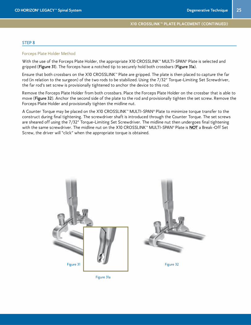
Forceps Plate Holder Method
With the use of the Forceps Plate Holder, the appropriate X10 CROSSLINK™ MULTI-SPAN® Plate is selected and gripped (Figure 31). The forceps have a notched tip to securely hold both crossbars (Figure 31a).
Ensure that both crossbars on the X10 CROSSLINK™ Plate are gripped. The plate is then placed to capture the far rod (in relation to the surgeon) of the two rods to be stabilized. Using the 7/32” Torque-Limiting Set Screwdriver, the far rod’s set screw is provisionally tightened to anchor the device to this rod.
Remove the Forceps Plate Holder from both crossbars. Place the Forceps Plate Holder on the crossbar that is able to move (Figure 32). Anchor the second side of the plate to the rod and provisionally tighten the set screw. Remove the Forceps Plate Holder and provisionally tighten the midline nut.
A Counter Torque may be placed on the X10 CROSSLINK™ MULTI-SPAN® Plate to minimize torque transfer to the construct during fi nal tightening. The screwdriver shaft is introduced through the Counter Torque. The set screws are sheared off using the 7/32” Torque-Limiting Set Screwdriver. The midline nut then undergoes fi nal tightening with the same screwdriver. The midline nut on the X10 CROSSLINK™ MULTI-SPAN® Plate is NOT a Break-Off Set Screw, the driver will “click” when the appropriate torque is obtained.
Figure 31 Figure 32
Figure 31a

26 CD HORIZON® LEGACY™ Spinal SystemDegenerative Technique
STEP 9
POSTOPERATIVE CARE AND MOBILIZATION
Prior to closure do a fi nal check to ensure that the plugs are symmetrically seated in the screw heads and sheared off, that the bone graft has not become dislodged during manipulation, and that a proper count of all sheared-off plug heads is correct (Figure 33).
Appropriate postoperative monitoring following evaluation of the extent of the surgical procedure and the patient’s overall medical status is essential. Deep vein anti-embolic treatment should be considered for all patients, along with active pulmonary toilet, fl uid balance, nutritional status, and monitoring of neurologic function. Prophylactic antibiotics may be continued for a brief duration following surgery until the wound seals. Finally, postoperative bracing may be considered for longer fusions or situations where signifi cant instability following instrumentation exists.
A structured progressive physical therapy program is essential to mobilize the patient in order to diminish postoperative complications and to rehabilitate the patient suffi ciently for discharge. During the inpatient rehabilitation period, patients should be carefully instructed in the appropriate methods of getting in and out of bed, stair climbing, and brace application, as well as how long to sit and various other activities of daily living. Patients that lag behind a normal recovery period proportional to the extent of their surgery should be expediently considered for transfer to a rehabilitation inpatient facility.
Finally, postoperative follow-up for a minimum of two years is crucial to assess the progression of fusion and, equally important, the patient’s clinical improvement.
Figure 33

27CD HORIZON® LEGACY™ Spinal System Degenerative Technique
IMPLANT EXPLANTATION
The CD HORIZON® LEGACY™ Set Screws (plugs) may be removed using the T27 Obturator and the Self-Retaining Break-Off Driver. The T27 Obturator is inserted into the working end of the Self-Retaining Break-Off Driver, so that the knurled portion of the T27 Obturator is fl ush with the driver. Insert the obturator tip through the Counter Torque, which should be seated on the screw, and into the plug, turning counter-clockwise until the plug has been removed. The pedicle screws may be removed using either the Multi Axial Screwdriver or the Self-Retaining Screwdriver in connection with the Ratcheting Handle. First, attach the Ratcheting Handle to the modular end of the driver. Next, fully engage the hex end of the screwdriver into the screw head, then, if utilizing the Multi Axial Screwdriver, thread the instrument sleeve into the screw head. Turn counter-clockwise until the pedicle screws have been removed.
If removal of an X10 CROSSLINK™ MULTI-SPAN® Plate is necessary, place the 7/32” Torque-Limiting Set Screwdriver over the midline nut and turn counter-clockwise to loosen. Place the 3.0mm Hex Head Shaft Removal Driver into a standard Medtronic Sofamor Danek Quick Connect Handle. Place the tip of the 3.0mm internal hex screwdriver into the set screw and confi rm that the 3.0mm tip is completely inserted and seated in the set screw so that the tip does not strip the hex. Turn the screwdriver counter-clockwise to loosen the set screw from the rod.

28 CD HORIZON® LEGACY™ Spinal SystemDegenerative Technique
5.5MM PRODUCT ORDERING INFORMATION
5.5MM RODS
CATALOG NUMBER DESCRIPTION
TITANIUM STAINLESS STEEL
869-022 868-021 5.5mm x 500mm Hex End Lined Rod
SET SCREWS
7540020 7560020 Break-Off Set Screw
7540120 7560120 Non Break-Off Set Screw
CONNECTORS
84505HT 84505H 5.5mm to 5.5mm Domino
84506HT 84506H 5.5mm to 6.35mm Domino
84509HT 84509H 5.5mm to 5.5mm Axial
84510HT 84510H 5.5mm to 6.35mm Axial
MULTI AXIAL SCREWS
75445525 75645525 5.5mm x 25mm
75445530 75645530 5.5mm x 30mm
75445535 75645535 5.5mm x 35mm
75445540 75645540 5.5mm x 40mm
75445545 75645545 5.5mm x 45mm
75445550 75645550 5.5mm x 50mm
75445555 75645555 5.5mm x 55mm
75446530 75646530 6.5mm x 30mm
75446535 75646535 6.5mm x 35mm
75446540 75646540 6.5mm x 40mm
75446545 75646545 6.5mm x 45mm
75446550 75646550 6.5mm x 50mm
75446555 75646555 6.5mm x 55mm
75447530 75647530 7.5mm x 30mm
75447535 75647535 7.5mm x 35mm
75447540 75647540 7.5mm x 40mm
75447545 75647545 7.5mm x 45mm
75447550 75647550 7.5mm x 50mm
75447555 75647555 7.5mm x 55mm
75447560 75647560 7.5mm x 60mm

29CD HORIZON® LEGACY™ Spinal System Degenerative Technique
MULTI AXIAL SCREWS (Available Upon Request)
CATALOG NUMBER DESCRIPTION
TITANIUM STAINLESS STEEL
75444020 75644020 4.0mm x 20mm
75444025 75644025 4.0mm x 25mm
75444030 75644030 4.0mm x 30mm
75444035 75644035 4.0mm x 35mm
75444040 75644040 4.0mm x 40mm
75444045 75644045 4.0mm x 45mm
75444050 75644050 4.0mm x 50mm
75444520 75644520 4.5mm x 20mm
75444525 75644525 4.5mm x 25mm
75444530 75644530 4.5mm x 30mm
75444535 75644535 4.5mm x 35mm
75444540 75644540 4.5mm x 40mm
75444545 75644545 4.5mm x 45mm
75444550 75644550 4.5mm x 50mm
75445020 75645020 5.0mm x 20mm
75445025 75645025 5.0mm x 25mm
75445030 75645030 5.0mm x 30mm
75445035 75645035 5.0mm x 35mm
75445040 75645040 5.0mm x 40mm
75445045 75645045 5.0mm x 45mm
75445050 75645050 5.0mm x 50mm
75446025 75646025 6.0mm x 25mm
75446030 75646030 6.0mm x 30mm
75446035 75646035 6.0mm x 35mm
75446040 75646040 6.0mm x 40mm
75446045 75646045 6.0mm x 45mm
75446050 75646050 6.0mm x 50mm
75446055 75646055 6.0mm x 55mm
75446060 75646060 6.0mm x 60mm
75446065 75646065 6.0mm x 65mm
5.5MM PRODUCT ORDERING INFORMATION (CONTINUED)
MULTI AXIAL SCREWS (Available Upon Request)
CATALOG NUMBER DESCRIPTION
TITANIUM STAINLESS STEEL
75446520 75646520 6.5mm x 20mm
75446525 75646525 6.5mm x 25mm
75446560 75646560 6.5mm x 60mm
75446565 75646565 6.5mm x 65mm
75447525 75647525 7.5mm x 25mm
75447565 75647565 7.5mm x 65mm
75447570 75647570 7.5mm x 70mm
75448525 75648525 8.5mm x 25mm
75448530 75648530 8.5mm x 30mm
75448535 75648535 8.5mm x 35mm
75448540 75648540 8.5mm x 40mm
75448545 75648545 8.5mm x 45mm
75448550 75648550 8.5mm x 50mm
75448555 75648555 8.5mm x 55mm
75448560 75648560 8.5mm x 60mm
75448565 75648565 8.5mm x 65mm

30 CD HORIZON® LEGACY™ Spinal SystemDegenerative Technique
6.35MM PRODUCT ORDERING INFORMATION
6.35MM RODS
CATALOG NUMBER DESCRIPTION
TITANIUM STAINLESS STEEL
969-022 968-021 6.35mm x 500mm Hex lined Rod
SET SCREWS
7640020 7660020 Break-Off Set Screw
7640120 7660120 Non Break-Off Set Screw
CONNECTORS
84505HT 84505H 6.35mm to 6.35mm Domino
84506HT 84506H 6.35mm to 5.5mm Domino
96509HT 96509H 6.35mm to 6.35mm Axial
84510HT 84510H 6.35mm to 5.5mm Axial
MULTI AXIAL SCREWS
76445525 76645525 5.5mm x 25mm
76445530 76645530 5.5mm x 30mm
76445535 76645535 5.5mm x 35mm
76445540 76645540 5.5mm x 40mm
76445545 76645545 5.5mm x 45mm
76445550 76645550 5.5mm x 50mm
76445555 76645555 5.5mm x 55mm
76446530 76646530 6.5mm x 30mm
76446535 76646535 6.5mm x 35mm
76446540 76646540 6.5mm x 40mm
76446545 76646545 6.5mm x 45mm
76446550 76646550 6.5mm x 50mm
76446555 76646555 6.5mm x 55mm
76447530 76647530 7.5mm x 30mm
76447535 76647535 7.5mm x 35mm
76447540 76647540 7.5mm x 40mm
76447545 76647545 7.5mm x 45mm
76447550 76647550 7.5mm x 50mm
76447555 76647555 7.5mm x 55mm
76447560 76647560 7.5mm x 60mm
31CD HORIZON® LEGACY™ Spinal System Degenerative Technique
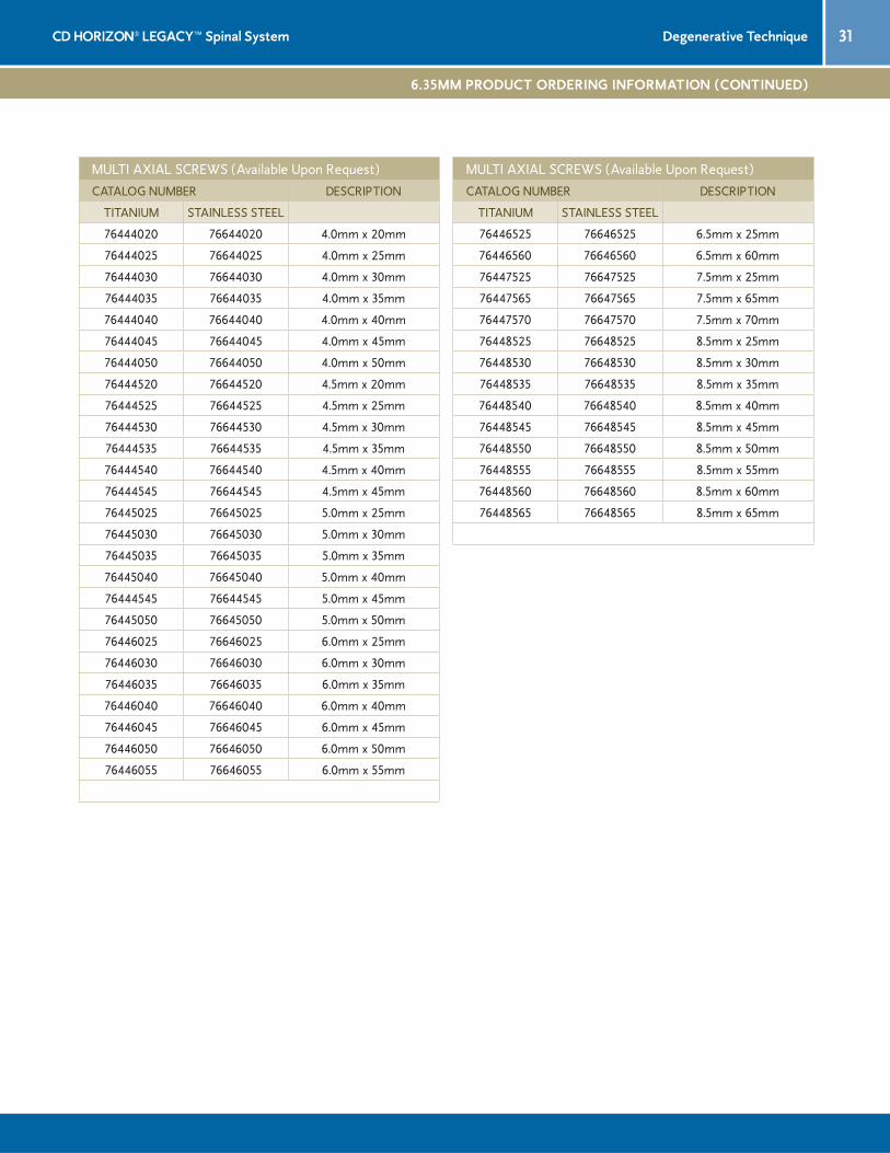
MULTI AXIAL SCREWS (Available Upon Request)
CATALOG NUMBER DESCRIPTION
TITANIUM STAINLESS STEEL
76444020 76644020 4.0mm x 20mm
76444025 76644025 4.0mm x 25mm
76444030 76644030 4.0mm x 30mm
76444035 76644035 4.0mm x 35mm
76444040 76644040 4.0mm x 40mm
76444045 76644045 4.0mm x 45mm
76444050 76644050 4.0mm x 50mm
76444520 76644520 4.5mm x 20mm
76444525 76644525 4.5mm x 25mm
76444530 76644530 4.5mm x 30mm
76444535 76644535 4.5mm x 35mm
76444540 76644540 4.5mm x 40mm
76444545 76644545 4.5mm x 45mm
76445025 76645025 5.0mm x 25mm
76445030 76645030 5.0mm x 30mm
76445035 76645035 5.0mm x 35mm
76445040 76645040 5.0mm x 40mm
76444545 76644545 5.0mm x 45mm
76445050 76645050 5.0mm x 50mm
76446025 76646025 6.0mm x 25mm
76446030 76646030 6.0mm x 30mm
76446035 76646035 6.0mm x 35mm
76446040 76646040 6.0mm x 40mm
76446045 76646045 6.0mm x 45mm
76446050 76646050 6.0mm x 50mm
76446055 76646055 6.0mm x 55mm
6.35MM PRODUCT ORDERING INFORMATION (CONTINUED)
MULTI AXIAL SCREWS (Available Upon Request)
CATALOG NUMBER DESCRIPTION
TITANIUM STAINLESS STEEL
76446525 76646525 6.5mm x 25mm
76446560 76646560 6.5mm x 60mm
76447525 76647525 7.5mm x 25mm
76447565 76647565 7.5mm x 65mm
76447570 76647570 7.5mm x 70mm
76448525 76648525 8.5mm x 25mm
76448530 76648530 8.5mm x 30mm
76448535 76648535 8.5mm x 35mm
76448540 76648540 8.5mm x 40mm
76448545 76648545 8.5mm x 45mm
76448550 76648550 8.5mm x 50mm
76448555 76648555 8.5mm x 55mm
76448560 76648560 8.5mm x 60mm
76448565 76648565 8.5mm x 65mm
32 CD HORIZON® LEGACY™ Spinal SystemDegenerative Technique
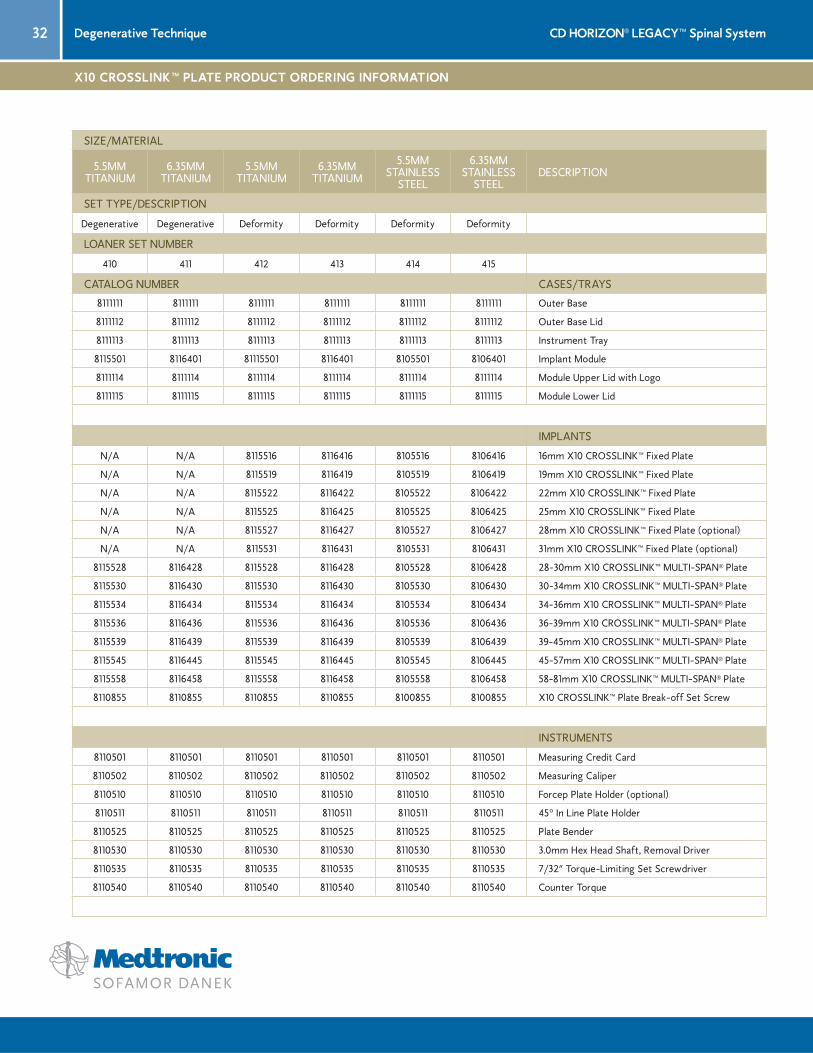
X10 CROSSLINK™ PLATE PRODUCT ORDERING INFORMATION
SIZE/MATERIAL
5.5MMTITANIUM
6.35MMTITANIUM
5.5MMTITANIUM
6.35MMTITANIUM
5.5MMSTAINLESS
STEEL
6.35MMSTAINLESS
STEELDESCRIPTION
SET TYPE/DESCRIPTION
Degenerative Degenerative Deformity Deformity Deformity Deformity
LOANER SET NUMBER
410 411 412 413 414 415
CATALOG NUMBER CASES/TRAYS
8111111 8111111 8111111 8111111 8111111 8111111 Outer Base
8111112 8111112 8111112 8111112 8111112 8111112 Outer Base Lid
8111113 8111113 8111113 8111113 8111113 8111113 Instrument Tray
8115501 8116401 81115501 8116401 8105501 8106401 Implant Module
8111114 8111114 8111114 8111114 8111114 8111114 Module Upper Lid with Logo
8111115 8111115 8111115 8111115 8111115 8111115 Module Lower Lid
IMPLANTS
N/A N/A 8115516 8116416 8105516 8106416 16mm X10 CROSSLINK™ Fixed Plate
N/A N/A 8115519 8116419 8105519 8106419 19mm X10 CROSSLINK™ Fixed Plate
N/A N/A 8115522 8116422 8105522 8106422 22mm X10 CROSSLINK™ Fixed Plate
N/A N/A 8115525 8116425 8105525 8106425 25mm X10 CROSSLINK™ Fixed Plate
N/A N/A 8115527 8116427 8105527 8106427 28mm X10 CROSSLINK™ Fixed Plate (optional)
N/A N/A 8115531 8116431 8105531 8106431 31mm X10 CROSSLINK™ Fixed Plate (optional)
8115528 8116428 8115528 8116428 8105528 8106428 28-30mm X10 CROSSLINK™ MULTI-SPAN® Plate
8115530 8116430 8115530 8116430 8105530 8106430 30-34mm X10 CROSSLINK™ MULTI-SPAN® Plate
8115534 8116434 8115534 8116434 8105534 8106434 34-36mm X10 CROSSLINK™ MULTI-SPAN® Plate
8115536 8116436 8115536 8116436 8105536 8106436 36-39mm X10 CROSSLINK™ MULTI-SPAN® Plate
8115539 8116439 8115539 8116439 8105539 8106439 39-45mm X10 CROSSLINK™ MULTI-SPAN® Plate
8115545 8116445 8115545 8116445 8105545 8106445 45-57mm X10 CROSSLINK™ MULTI-SPAN® Plate
8115558 8116458 8115558 8116458 8105558 8106458 58-81mm X10 CROSSLINK™ MULTI-SPAN® Plate
8110855 8110855 8110855 8110855 8100855 8100855 X10 CROSSLINK™ Plate Break-off Set Screw
INSTRUMENTS
8110501 8110501 8110501 8110501 8110501 8110501 Measuring Credit Card
8110502 8110502 8110502 8110502 8110502 8110502 Measuring Caliper
8110510 8110510 8110510 8110510 8110510 8110510 Forcep Plate Holder (optional)
8110511 8110511 8110511 8110511 8110511 8110511 45° In Line Plate Holder
8110525 8110525 8110525 8110525 8110525 8110525 Plate Bender
8110530 8110530 8110530 8110530 8110530 8110530 3.0mm Hex Head Shaft, Removal Driver
8110535 8110535 8110535 8110535 8110535 8110535 7/32” Torque-Limiting Set Screwdriver
8110540 8110540 8110540 8110540 8110540 8110540 Counter Torque

33CD HORIZON® LEGACY™ Spinal System Degenerative Technique
IMPORTANT INFORMATION ON THE CD HORIZON® SPINAL SYSTEM
PURPOSE:
The CD HORIZON® Spinal System is intended to help provide immobilization and stabilization of spinal segments as an adjunct to fusion of the thoracic, lumbar, and/or sacral spine.
DESCRIPTION:
The CD HORIZON® Spinal System consists of a variety of shapes and sizes of rods, hooks, screws, CROSSLINK® Plates, staples and connecting components, as well as implant components from other Medtronic Sofamor Danek spinal systems, which can be rigidly locked into a variety of configurations, with each construct being tailor-made for the individual case.
Certain implant components from other Medtronic Sofamor Danek spinal systems can be used with the CD HORIZON® Spinal System. These components include TSRH® rods, hooks, screws, plates, CROSSLINK®
plates, connectors, staples and washer, GDLH™ rods, hooks, connectors and CROSSLINK® bar and connectors; LIBERTY™ rods and screws; DYNALOK PLUS® and DYNALOK® CLASSIC bolts along with rod/bolt connectors; and Sofamor Danek Multi-Axial rods and screws. Please note that certain components are specifically designed to connect to ø3.5mm, ø4.5mm, ø5.5mm rods or ø6.35mm rods, while other components can connect to both ø.5mm rods and ø6.35mm rods. Care should be taken so that the correct components are used in the spinal construct.
CD HORIZON® hooks are intended for posterior use only. CD HORIZON® staples and CD HORIZON® ECLIPSE® rods and associated screws are intended for anterior use only. However, for patients of smaller stature, CD HORIZON® 4.5mm rods and associated components may be used posteriorly.
The CD HORIZON® Spinal System implant components are fabricated from medical grade stainless steel, medical grade titanium, titanium alloy, medical grade cobalt-chromium-molybdenum alloy, or medical grade PEEK OPTIMA-LT1. Certain CD HORIZON® Spinal System components may be coated with hydroxyapatite. No warranties express, or implied, are made. Implied warranties of merchantability and fitness for a particular purpose or use are specifically excluded. See the MSD Catalog for further information about warranties and limitations of liability
Never use stainless steel and titanium implant components in the same construct.
Medical grade titanium, titanium alloy and/or medical grade cobalt-chromium-molybdenum alloy may be used together. Never use titanium, titanium alloy and/or medical grade cobalt-chromium-molybdenum alloy with stain-less steel in the same construct.
The CD HORIZON® Spinal System also includes anterior staples made of Shape Memory Alloy (Nitinol – NiTi). Shape Memory Alloy is compatible with titanium, titanium alloy and cobalt-chromium-molybdenum alloy. Do not use with stainless steel.
PEEK OPTIMA-LT1 implants may be used with stainless steel, titanium or cobalt-chromium-molybdenum alloy implants. CD HORIZON® PEEK Rods are not to be used with CROSSLINK® Plates.
To achieve best results, do not use any of the CD HORIZON® Spinal System implant components with compo-nents from any other system or manufacturer unless specifically allowed to do so in this or another Medtronic Sofamor Danek document. As with all orthopaedic and neurosurgical implants, none of the CD HORIZON® Spinal System components should ever be reused under any circumstances.
INDICATIONS:
The CD HORIZON® Spinal System is intended for posterior, non-cervical fixation for the following indications: degenerative disc disease (defined as back pain of discogenic origin with degeneration of the disc confirmed by history and radiographic studies); spondylolisthesis; trauma (i.e., fracture or dislocation); spinal stenosis; curva-tures (i.e., scoliosis, kyphosis and/or lordosis); tumor; pseudarthrosis; and/or failed previous fusion.
When used in a percutaneous, non-cervical, posterior approach with the SEXTANT™ instrumentation, the CD HORIZON® screws are intended for the following indications: degenerative disc disease (defined as back pain of discogenic origin with degeneration of the disc confirmed by history and radiographic studies); spondylolisthesis; trauma (i.e., fracture or dislocation); spinal stenosis; curvatures (i.e., scoliosis, kyphosis and/or lordosis); tumor; pseudoarthrosis; and/or failed previous fusion.
Except for hooks, when used as an anterolateral thoracic/lumbar system, CD HORIZON® components such as ECLIPSE® components are intended for the following indications: (1) degenerative disc disease (as defined by back pain of discogenic origin with degeneration of the disc confirmed by patient history and radiographic stud-ies), (2) spinal stenosis, (3) spondylolisthesis, (4) spinal deformities (i.e., scoliosis, kyphosis, and/or lordosis), (5) fracture, (6) pseudarthrosis, (7) tumor resection, and/or (8) failed previous fusion.
The CD HORIZON® SPINOUS PROCESS Plate is posterior, non-pedicle supplemental fixation device, intended for use in the non-cervical spine (T1 – S1). It is intended for plate fixation/attachment to spinous process for the purpose of achieving supplemental fusion in the following conditions: degenerative disc disease - defined as back pain of discogenic origin with degeneration of the disc confirmed by history and radiographic studies; spondylo-listhesis; trauma (i.e., fracture or dislocation); and/or tumor.
The CD HORIZON® LEGACY 3.5mm rod and associated components, when used as a pedicle screw fixation system of the non-cervical posterior spine in skeletally mature patients, are indicated for one or more of the following: (1) degenerative spondylolisthesis with objective evidence of neurologic impairment, (2) fracture, (3) dislocation, (4) scoliosis, (5) kyphosis, (6) spinal tumor, and/or (7) failed previous fusion (pseudarthrosis).
In addition, when used as a pedicle screw fixation system, the CD HORIZON® LEGACY 3.5mm rod and associ-ated components, are indicated for skeletally mature patients: (a) having severe spondylolisthesis (Grades 3 and 4) of the fifth lumbar-first sacral (L5-S1) vertebral joint; (b) who are receiving fusions using autogenous bone graft only; (c) who are having the device fixed or attached to the lumbar and sacral spine (L3 and below); and (d) who are having the device removed after the development of a solid fusion mass.
When used as a pedicle screw system in skeletally mature patients, the CD HORIZON® Spinal System PEEK rods and associated components are intended to provided immobilization and stabilization of spinal segments as an adjunct to fusion in the treatment of the following acute and chronic instabilities of the thoracic, lumbar and sacral spine: (1) degenerative spondylolisthesis with objective evidence of neurologic impairment, (2) kyphosis, and/or (3) failed previous fusion. Additionally, when used as a pedicle screw device, the CD HORIZON® Spinal System PEEK rod constructs are indicated for use in patients who: (1) are receiving fusion with autogenous graft only, (2) who are having the device attached to the lumbar or sacral spine, and/or (3) who are having the device removed after the development of a solid fusion mass.
In order to achieve additional levels of fixation, the CD HORIZON® Spinal System rods may be connected to the VERTEX™ Reconstruction System with the VERTEX™ rod connector. Refer to the VERTEX™ Reconstruction System Package Insert for a list of the VERTEX™ indications of use.
CONTRAINDICATIONS:
Contraindications include, but are not limited to:
1. Active infectious process or significant risk of infection (immuno compromise).
2. Signs of local inflammation.
3. Fever or leukocytosis.
4. Morbid obesity.
5. Pregnancy.
6. Mental illness.
7. Grossly distorted anatomy caused by congenital abnormalities.
8. Any other medical or surgical condition which would preclude the potential benefit of spinal implant surgery, such as the presence of congenital abnormalities, elevation of sedimentation rate unexplained by other diseases, elevation of white blood count (WBC), or a marked left shift in the WBC differential count.
9. Rapid joint disease, bone absorption, osteopenia, osteomalacia and/or osteoporosis.
10. Suspected or documented metal allergy or intolerance.
11. Any case not needing a bone graft and fusion.
12. Any case where the implant components selected for use would be too large or too small to achieve a suc-cessful result.
13. Any patient having inadequate tissue coverage over the operative site or inadequate bone stock or quality.
14. Any patient in which implant utilization would interfere with anatomical structures or expected physiological performance.
15. Any patient unwilling to follow postoperative instructions.
16. Any case not described in the indications.
POTENTIAL ADVERSE EVENTS:
All of the possible adverse events associated with spinal fusion surgery without in strumentation are possible. With instrumentation, a list ing of potential adverse events includes, but is not limited to:
1. Early or late loosen ing of any or all of the compo nents.
2. Disassembly, bend ing, and/or breakage of any or all of the components.
3. Foreign body (allergic) reaction to implants, debris, corrosion products (from crevice, fretting, and/or general corrosion), including metallosis, staining, tumor forma tion, and/or autoimmune disease.
4. Pressure on the skin from component parts in patients with inadequate tis sue cov erage over the implant possibly causing skin pene tration, irritation, fibrosis, neurosis, and/or pain. Bursitis. Tissue or nerve damage caused by improper positioning and placement of implants or instruments.
5. Post-operative change in spinal cur vature, loss of cor rec tion, height, and/or reduc tion.
6. Infection.
7. Dural tears, pseudomeningocele, fistula, persistent CSF leakage, meningitis.
8. Loss of neurological function (e.g., sensory and/or motor), including paralysis (complete or incomplete), dysesthe sias, hyperesthesia, anesthesia, paresthesia, appear ance of radiculopa thy, and/or the de velopment or con tinuation of pain, numb ness, neuroma, spasms, sensory loss, tingling sensation, and/or visual defi-cits.
9. Cauda equina syndrome, neuropathy, neurological deficits (transient or permanent), paraplegia, paraparesis, reflex deficits, irritation, arachnoiditis, and/or muscle loss.
10. Urinary retention or loss of bladder control or other types of urological system compromise.
11. Scar formation possibly causing neurological compromise or compression around nerves and/or pain.
12. Fracture, microfracture, resorption, damage, or pene tration of any spinal bone (including the sacrum, pedicles, and/or vertebral body) and/or bone graft or bone graft harvest site at, above, and/or be low the level of surgery. Retropulsed graft.
13. Herniated nucleus pulposus, disc disruption or degeneration at, above, or below the level of surgery.
14. Non-union (or pseud arthrosis). Delayed union. Mal-union.
15. Cessation of any poten tial growth of the operated por tion of the spine.
16. Loss of or increase in spinal mobility or function.
17. Inability to perform the activities of daily living.
18. Bone loss or decrease in bone density, possibly caused by stresses shield ing.
19. Graft donor site compli cations including pain, fracture, or wound heal ing problems.
20. Ileus, gastri tis, bowel obstruction or loss of bowel control or other types of gastrointestinal system compro-mise.
21. Hemorrhage, hematoma, occlusion, seroma, edema, hypertension, embolism, stroke, excessive bleed ing, phlebitis, wound necrosis, wound dehiscence, damage to blood vessels, or other types of cardiovascular system compromise.
22. Reproductive system compromise, including sterility, loss of con sortium, and sexual dysfunction.
23. Development of respira tory problems, e.g. pul monary embolism, atelectasis, bron chitis, pneumonia, etc.
24. Change in mental status.
25. Death.
Note: Additional surgery may be necessary to correct some of these potential adverse events.
WARNING:
The safety and effectiveness of pedicle screw spinal systems have been established only for spinal conditions with significant mechanical instability or deformity requiring fusion with instrumentation. These conditions are significant mechanical instability or deformity of the thoracic, lumbar, and sacral spine secondary to degenera-tive spondylolisthesis with objective evidence of neurologic impairment, fracture, dislocation, scoliosis, kyphosis, spinal tumor, and failed previous fusion (pseudarthrosis). The safety and effectiveness of this device for any other conditions are unknown. The implants are not prostheses.
In the absence of fusion, the instrumentation and/or one or more of its components can be expected to pull out, bend or fracture as a result of exposure to every day mechanical stresses.
PRECAUTION:
The implantation of pedicle screw spinal systems should be performed only by experienced spinal surgeons with specific training in the use of this pedicle screw spinal system because this is a technically demanding procedure presenting a risk of serious injury to the patient.
A successful result is not always achieved in every surgical case. This fact is especially true in spinal surgery where many extenuating circumstances may compromise the results. This device system is not intended to be the sole means of spinal support. Use of this product without a bone graft or in cases that develop into a non-union will not be successful. No spinal implant can withstand body loads without the support of bone. In this event, bending, loosening, disassembly and/or breakage of the device(s) will eventually occur.
Preoperative and operating procedures, including knowledge of surgical techniques, good reduction, and proper selection and placement of the implants are important considerations in the successful utilization of the system by the surgeon. Further, the proper selection and compliance of the patient will greatly affect the results. Patients who smoke have been shown to have an increased incidence of non-unions. These patients should be advised of this fact and warned of this consequence. Obese, malnourished, and/or alcohol abuse patients are also poor candidates for spine fusion. Patients with poor muscle and bone quality and/or nerve paralysis are also poor candidates for spine fusion.
PHYSICIAN NOTE:
Although the physician is the learned intermediary between the company and the patient, the important medi-cal information given in this document should be conveyed to the patient.
USA For US Audiences Only
CAUTION: Federal law (USA) restricts these devices to sale by or on the order of a physician.
Other preoperative, intraoperative, and postoperative warnings and precautions are as follows:

34 CD HORIZON® LEGACY™ Spinal SystemDegenerative Technique
IMPORTANT INFORMATION ON THE CD HORIZON® SPINAL SYSTEM
IMPLANT SELECTION:
The selection of the proper size, shape and design of the implant for each patient is crucial to the success of the procedure. Metallic surgical implants are subject to repeated stresses in use, and their strength is limited by the need to adapt the design to the size and shape of human bones. Unless great care is taken in patient selection, proper placement of the implant, and postoperative management to minimize stresses on the implant, such stresses may cause metal fatigue and consequent breakage, bending or loosening of the device before the healing process is complete, which may result in further injury or the need to remove the device prematurely.
DEVICE FIXATION:
In cases where a percutaneous posterior approach is used refer to the CD HORIZON® SEXTANT™ surgical technique.
MEDTRONIC SOFAMOR DANEK CD HORIZON® Spinal System instrumentation contains 3.5mm, 4.5 mm, 5.5mm and/or 6.35mm rods and implants, which are intended to be used with device specific instruments.
For self breaking plugs, always hold the assembly with the Counter Torque device. Tighten and break-off the head of the plug to leave the assembly at optimum fixation security. After the upper part of the self breaking plug has been sheared off, further re-tightening is not necessary and not recommended. The head part should not remain in the patient. AFTER THE UPPER PART OF THE SELF BREAKING PLUG HAS BEEN SHEARED OFF, RE-ADJUSTMENT IS NOT POSSIBLE UNLESS THE PLUG IS REMOVED AND REPLACED WITH A NEW ONE.
When using DTT Transverse Links , the M6 plug should be tightened to between 8 and 9 Nm.( 70 to 80 inch-lbs).
CD HORIZON® PEEK Rods are not to be used with CROSSLINK® Plates.
PREOPERATIVE:
1. Only patients that meet the criteria described in the indications should be selected.
2. Patient conditions and/or pre dispositions such as those addressed in the aforementioned contraindica-tions should be avoided.
3. Care should be used in the handling and storage of the implant components. The implants should not be scratched or otherwise damaged. Implants and instruments should be protected during storage, espe-cially from corrosive environments.
4. An adequate inventory of implants should be available at the time of surgery, normally a quantity in excess of what is expected to be used.
5. Since mechanical parts are involved, the surgeon should be familiar with the various components before using the equipment and should personally assemble the devices to verify that all parts and necessary instruments are present before the surgery begins. The CD HORIZON® Spinal System components (described in the DESCRIPTION section) are not to be combined with the components from another manufacturer.
6. All components and instruments should be cleaned and sterilized before use. Additional sterile compo-nents should be available in case of an unexpected need.
INTRAOPERATIVE:
1. Extreme caution should be used around the spinal cord and nerve roots. Damage to the nerves will cause loss of neurological functions.
2. Breakage, slippage, or misuse of instruments or implant components may cause injury to the patient or operative personnel.
3. The rods should not be repeatedly or excessively bent. The rods should not be reverse bent in the same location. Use great care to insure that the implant surfaces are not scratched or notched, since such actions may reduce the functional strength of the construct. If the rods are cut to length, they should be cut in such a way as to create a flat, non-sharp surface perpendicular to the midline of the rod. Cut the rods outside the operative field. Whenever possible, use pre-cut rods of the length needed.
4. Utilize an imaging system to facilitate surgery.
5. To insert a screw properly, a guide wire should first be used, followed by a sharp tap. Caution: Be care-ful that the guide-wire, if used, is not inserted too deep, becomes bent, and/or breaks. Ensure that the guide-wire does not advance during tapping or screw insertion. Remove the guide-wire and make sure it is intact. Failure to do so may cause the guide wire or part of it to advance through the bone and into a location that may cause damage to underlying structures.
6. Caution: Do not overtap or use a screw/bolt that is either too long or too large. Overtapping, using an incorrectly sized screw/bolt, or accidentally advancing the guidewire during tap or screw/bolt insertion, may cause nerve damage, hemorrhage, or the other possible adverse events listed elsewhere in this package insert. If screws/bolts are being inserted into spinal pedicles, use as large a screw/bolt diameter as will fit into each pedicle.
7. Bone graft must be placed in the area to be fused and graft material must extend from the upper to the lower vertebrae being fused.
8. To assure maximum stability, two or more CROSSLINK® plates or DTT Transverse Links on two bilaterally placed, continuous rods, should be used whenever possible.
9. Before closing the soft tissues, provisionally tighten (finger tighten) all of the nuts or screws, especially screws or nuts that have a break-off feature. Once this is completed go back and firmly tighten all of the screws and nuts. Recheck the tightness of all nuts or screws after finishing to make sure that none loosened during the tightening of the other nuts or screws. Failure to do so may cause loosening of the other components.
POSTOPERATIVE:
The physician’s postoperative directions and warnings to the patient, and the corresponding patient compli-ance, are extremely important.
1. Detailed instructions on the use and limitations of the device should be given to the patient. If partial weight-bearing is recommended or required prior to firm bony union, the patient must be warned that bending, loosening and/or breakage of the device(s) are complications which may occur as a result of excessive or early weight-bearing or muscular activity. The risk of bending, loosening, or breakage of a temporary internal fixation device during postoperative rehabilitation may be increased if the patient is active, or if the patient is debilitated or demented. The patient should be warned to avoid falls or sudden jolts in spinal position.
2. To allow the maximum chances for a successful surgical result, the patient or devices should not be exposed to mechanical vibrations or shock that may loosen the device construct. The patient should be warned of this possibility and instructed to limit and restrict physical activities, especially lifting and twist-ing motions and any type of sport participation. The patient should be advised not to smoke tobacco or utilize nicotine products, or to consume alcohol or non-steroidals or anti-inflammatory medications such as aspirin during the bone graft healing process.
3. The patient should be advised of their inability to bend or rotate at the point of spinal fusion and taught to compensate for this permanent physical restriction in body motion.
4. Failure to immobilize a delayed or non-union of bone will result in excessive and repeated stresses on the implant. By the mechanism of fatigue, these stresses can cause the eventual bending, loosening, or breakage of the device(s). It is important that immobilization of the spinal surgical site be maintained until firm bony union is established and confirmed by roentgenographic examination. If a state of non-union persists or if the components loosen, bend, and/or break, the device(s) should be revised and/or removed immediately before serious injury occurs. The patient must be adequately warned of these hazards and closely supervised to insure cooperation until bony union is confirmed.
5. As a precaution, before patients with implants receive any subsequent surgery (such as dental proce-dures), prophylactic antibiotics may be considered, especially for high-risk patients.
6. The CD HORIZON® Spinal System implants are temporary internal fixation devices. Internal fixation devices are designed to stabilize the operative site during the normal healing process. After the spine is fused, these devices serve no functional purpose and may be removed. While the final decision on implant removal is, of course, up to the surgeon and patient, in most patients, removal is indicated because the implants are not intended to transfer or support forces developed during normal activities. If the device is not removed following completion of its intended use, one or more of the following complica-tions may occur: (1) Corrosion, with localized tissue reaction or pain; (2) Migration of implant position, possibly resulting in injury; (3) Risk of additional injury from postoperative trauma; (4) Bending, loosening and breakage, which could make removal impractical or difficult; (5) Pain, discomfort, or abnormal sensa-tions due to the presence of the device; (6) Possible increased risk of infection; (7) Bone loss due to stress shielding; and (8) Potential unknown and/or unexpected long term effects such as carcinogenesis. Implant removal should be followed by adequate postoperative management to avoid fracture, re-fracture, or other complications.
7. Any retrieved devices should be treated in such a manner that reuse in another surgical procedure is not possible. As with all orthopedic implants, the CD HORIZON® Spinal System components should never be reused under any circumstances.
PACKAGING:
Packages for each of the components should be intact upon receipt. If a loaner or consignment system is used, all sets should be carefully checked for completeness and all components including instruments should be carefully checked to ensure that there is no damage prior to use. Damaged packages or products should not be used, and should be returned to Medtronic Sofamor Danek.
CLEANING AND DECONTAMINATION:
Unless just removed from an unopened Medtronic Sofamor Danek package, all instruments and implants must be disassembled (if applicable) and cleaned using neutral cleaners before sterilization and introduction into a sterile surgical field or (if applicable) return of the product to Medtronic Sofamor Danek. Cleaning and disinfecting of instruments can be performed with aldehyde-free solvents at higher temperatures. Cleaning and decontamination must include the use of neutral cleaners followed by a deionized water rinse.
Note: certain cleaning solutions such as those containing formalin, glutaraldehyde, bleach and/or other alka-line cleaners may damage some devices, particularly instruments; these solutions should not be used. Also, many instruments require disassembly before cleaning.
All products should be treated with care. Improper use or handling may lead to damage and/or possible improper functioning of the device.
STERILIZATION:
Unless marked sterile and clearly labeled as such in an unopened sterile package provided by the company, all implants and instruments used in surgery must be sterilized by the hospital prior to use. Remove all packaging materials prior to sterilization. Only sterile products should be placed in the operative field. Unless specified elsewhere, these products are recommended to be steam sterilized by the hospital using one of the three sets of process parameters below:
METHOD CYCLE TEMPEATURE EXPOSURE TIMESteam Pre-Vacuum 270° F (132° C) 4 MinutesSteam Gravity 250° F (121° C) 60 MinutesSteam* Pre-Vacuum* 273° F (134° C)* 20 Minutes*Steam* Gravity* 273° F (134° C)* 20 Minutes*
NOTE: Because of the many variables involved in sterilization, each medical facility should calibrate and verify the sterilization process (e.g., temperatures, times) used for their equipment. *For outside the United States, some non-U.S. Health Care Authorities recommend sterilization according to these parameters so as to minimize the potential risk of transmission of Creutzfeldt-Jakob disease, especially of surgical instruments that could come into contact with the central nervous system.
PRODUCT COMPLAINTS:
Any Health Care Professional (e.g., customer or user of this system of products), who has any complaints or who has experienced any dissatisfaction in the product quality, identity, durability, reliability, safety, effectiveness and/or performance, should notify the distributor, Medtronic Sofamor Danek. Further, if any of the implanted spinal system component(s) ever “malfunctions,” (i.e., does not meet any of its performance specifications or otherwise does not perform as intended), or is suspected of doing so, the distributor should be notified immediately. If any Medtronic Sofamor Danek product ever “malfunctions” and may have caused or contributed to the death or serious injury of a patient, the distributor should be notified immediately by telephone, FAX or written correspondence. When filing a complaint, please provide the component(s) name and number, lot number(s), your name and address, the nature of the complaint and notification of whether a written report from the distributor is requested.
FOR FURTHER INFORMATION:
Medtronic B.V.Earl Bakkenstraat 106422 PJ HeerlenThe NetherlandsTel: + 31 45 566 80 00
1800 Pyramid PlaceMemphis, TN 38132Telephone 800 876 3133 (In U.S.A.) 901 396 3133 (Outside of U.S.A.)FAX 901 396 0356
©2005 MEDTRONIC SOFAMOR DANEK. All rights reserved.

35CD HORIZON® LEGACY™ Spinal System Degenerative Technique
NOTES

36 CD HORIZON® LEGACY™ Spinal SystemDegenerative Technique
NOTES


LITLEGDEGST6IRN1801/016©2006 Medtronic Sofamor Danek USA, Inc. All Rights Reserved.
MEDTRONIC SOFAMOR DANEK USA, INC.Spinal Division Worldwide Headquarters1800 Pyramid PlaceMemphis, TN 38132(901) 396-3133(800) 876-3133Customer Service: (800) 933-2635
www.sofamordanek.comFor more information go to www.myspinetools.com
The surgical technique shown is for illustrative purposes only. The technique(s) actually employed in each case will always depend upon the medical judgement of the surgeon exercised before and during surgery as to the best mode of treatment for each patient.