cciaiiaaciac - ministerio de fomento€¦ · to cedeira, where they took more photographs. they...
TRANSCRIPT

COMISIÓN DEINVESTIGACIÓNDE ACCIDENTESE INCIDENTES DEAVIACIÓN CIVIL
CIAIACCIAIAC
ReportA-035/2016
Accident involving a Robin DR-400-180 aircraft, registration EC-KFG, in Villanueva del Condado, municipality of Vegas del Condado (León, Spain), on 6 September 2016


Report
A-035/2016
Accident involving a Robin DR-400-180 aircraft, registration EC-KFG, in Villanueva del Condado,
municipality of Vegas del Condado (León, Spain), on 6 September 2016
GOBIERNODE ESPAÑA
MINISTERIODE FOMENTO
SUBSECRETARÍA
COMISIÓN DE INVESTIGACIÓNDE ACCIDENTES E INCIDENTES DE AVIACIÓN CIVIL

Edita: Centro de Publicaciones Secretaría General Técnica Ministerio de Fomento ©
NIPO: 161-17-156-2
Diseño, maquetación e impresión: Centro de Publicaciones
COMISIÓN DE INVESTIGACIÓN DE ACCIDENTES E INCIDENTES DE AVIACIÓN CIVIL
Tel.: +34 91 597 89 63 E-mail: [email protected] C/ Fruela, 6Fax: +34 91 463 55 35 http://www.ciaiac.es 28011 Madrid (España)

F o r e w o r d
This report is a technical document that reflects the point of view of the Civil Aviation Accident and Incident Investigation Commission (CIAIAC) regarding the circumstances of the accident object of the investigation, and its probable causes and consequences.
In accordance with the provisions in Article 5.4.1 of Annex 13 of the International Civil Aviation Convention; and with articles 5.5 of Regulation (UE) nº 996/2010, of the European Parliament and the Council, of 20 October 2010; Article 15 of Law 21/2003 on Air Safety and articles 1., 4. and 21.2 of Regulation 389/1998, this investigation is exclusively of a technical nature, and its objective is the prevention of future civil aviation accidents and incidents by issuing, if necessary, safety recommendations to prevent from their reoccurrence. The investigation is not pointed to establish blame or liability whatsoever, and it’s not prejudging the possible decision taken by the judicial authorities. Therefore, and according to above norms and regulations, the investigation was carried out using procedures not necessarily subject to the guarantees and rights usually used for the evidences in a judicial process.
Consequently, any use of this report for purposes other than that of preventing future accidents may lead to erroneous conclusions or interpretations.
This report was originally issued in Spanish. This English translation is provided for information purposes only.


Report A-035/2016
vii
Ta b l e o f c o n t e n t s
Abbreviations ............................................................................................................................... ix
Synopsis ........................................................................................................................................ xi
1. Factual information ............................................................................................................... 1
1.1. History of the flight........................................................................................................ 1 1.2. Injuries to persons .......................................................................................................... 1 1.3. Damage to aircraft ......................................................................................................... 2 1.4. Other damage ................................................................................................................ 2 1.5. Personnel information .................................................................................................... 2 1.6. Aircraft information ........................................................................................................ 2 1.6.1. General information ......................................................................................... 2 1.6.2. Stall speed in relation to bank angle and flap configuration ........................... 4 1.7. Meteorological information ............................................................................................ 4 1.7.1. General conditions ........................................................................................... 4 1.7.2. Conditions in the accident area ....................................................................... 4 1.8. Aids to navigation .......................................................................................................... 5 1.9. Communications ............................................................................................................ 5 1.9.1. Control tower at the A Coruña Airport ........................................................... 5 1.9.2. Control tower at the León Airport ................................................................... 6 1.10. Aerodrome information .................................................................................................. 7 1.11. Flight recorders .............................................................................................................. 7 1.11.1. GPS .................................................................................................................. 7 1.12. Wreckage and impact information ................................................................................. 10 1.12.1. General information on the distribution of the wreckage ................................ 10 1.12.2. Condition of the aircraft wreckage .................................................................. 12 1.13. Medical and pathological information ............................................................................ 15 1.14. Fire ................................................................................................................................. 15 1.15. Survival aspects .............................................................................................................. 15 1.16. Tests and research .......................................................................................................... 15 1.16.1. Eyewitness statements ..................................................................................... 15 1.16.1.1. Worker at the municipal pool......................................................... 15 1.16.1.2. Resident in one of the houses ........................................................ 16 1.17. Organizational and management information ................................................................ 16 1.18. Additional information ................................................................................................... 17 1.19. Useful or effective investigation techniques ................................................................... 17 1.19.1. Photographs taken during the accident flight .................................................. 17 1.19.2. Synchronization of the times on the camera and the GPS unit ....................... 17
2. Analysis ................................................................................................................................ 19 2.1. Analysis of the tracks and possible impact sequence ..................................................... 19 2.2. Analysis of the aircraft wreckage ................................................................................... 20 2.3. Procedural analysis of the flight ..................................................................................... 21 2.4. Determining the aircraft’s flight path ............................................................................. 21 2.5. Analysis of the circling maneuver ................................................................................... 23 2.6. Stall in a turn ................................................................................................................. 25

Report A-035/2016
viii
3. Conclusions ............................................................................................................................ 27
3.1. Findings ......................................................................................................................... 27 3.2. Causes/Contributing factors ........................................................................................... 28
4. Safety recommendations ...................................................................................................... 29

Report A-035/2016
ix
A b b r e v i a t i o n s
º ‘ “ Sexagesimal degrees, minutes and secondsºC Degrees centigradeAEMET Spain’s National Weather AgencyAESA Spain’s National Aviation Safety AgencyAGL Above ground levelAUW All-up weightCAVOK Visibility, clouds and current weather better than prescribed values or conditions CPL Commercial pilot licenseCTA Control areaCTR Control zoneESE East southeastFI Flight instructorft/min Feet per minuteGPS Global positioning systemHP Horsepowerh HourshPa HectopascalsICAO International Civil Aviation OrganizationIGN Spain’s National Geographic InstituteIR Instrument flightKg KilogramsKm KilometersKm/h Kilometers/hourKt Knotsl Litersm Metersm2 Square metersm/min Meters per minutem/s Meters per secondMEP Multi-engine pistonMin MinutesmHz MegahertzN/A Not affected / not availablePPL Private pilot licenseQNH Altimeter subscale setting to obtain elevation when on the groundrad/s Radians per secondRPM Revolutions per minutes SecondsSEP Single-engine pistonSERA Implementing Regulation (EU) No 932/2012, laying down the common rules of the air and operational provisions regarding services and procedures in air navigation (Standarised European Rules of the Air)SPS Standard Positioning ServiceSW SouthwestTACC Terminal area control centerTAFYR Trabajos Aéreos Fotografía y Reportajes S.L.UTC Coordinated universal timeVA Maneuvering speedVNE Never-exceed speed


Report A-035/2016
xi
S y n o p s i s
Owner and Operator: TAFYR
Aircraft: ROBIN DR-400-180
Date and time of accident: Tuesday, 6 September 2016 at 16:12 local time
Site of accident: Villanueva del Condado. Municipality of Vegas del Condado (León, Spain)
2, killed
Aerial work – Commercial – Aerial photography
Maneuvering – low altitude flight
Persons onboard:
Type of flight:
Phase of flight:
Date of approval: 26 April 2017
Summary of the event
The aircraft had taken off from the A Coruña Airport at 14:39. The flight plan indicated that the destination was the Pamplona Airport. It was an aerial photography flight during which the crew planned to do photographic work along their planned route.
At about 16:10, the aircraft reached the town of Villanueva del Condado (León) and started flying in a circle at a low altitude around a group of various buildings inside a plot that is located some 750 m northwest of the town of Villanueva del Condado.
An eyewitness who was in the municipal pool stated that he saw the aircraft fly overhead, then over a group of black poplar trees before banking to the right. Immediately afterward he saw the nose of the aircraft drop sharply.
The aircraft violently impacted the ground a few meters ahead, resulting in the death of both occupants and in the destruction of the aircraft.
The investigation has determined that the accident occurred as the aircraft stalled while circling over a group of houses the occupants wanted to photograph.

Report A-035/2016
xii
The following factors contributed to the accident:
• The low circling altitude.
• Circling the group of houses with a small turn radius, which required an excessive bank angle.

Report A-035/2016
1
1. FACTUAL INFORMATION
1.1. History of the flight
The aircraft had taken off from the A Coruña Airport at 14:39. The flight plan indicated that the destination was the Pamplona Airport. It was an aerial photography flight during which the crew intended to do photographic work along their planned route.
According to information in the flight plan filed by the crew, the flight had a planned duration of 6 h. The aircraft had a range of 7 h.
On the day of the event, immediately before taking off, the aircraft had been refueled with 110 liters of AVGAS 100LL.
After taking off, the aircraft headed north and flew to the town of Narón (A Coruña), which they circled once while they took several photographs. From there the aircraft flew to Cedeira, where they took more photographs. They then headed to Villadangos del Páramo (León) to take more photographs, after which they proceeded northeast.
At about 16:10, the aircraft reached the town of Villanueva del Condado (León).
Based on information provided by eyewitnesses, the aircraft started to circle a group of buildings at a low altitude. These buildings are inside a plot that is located some 750 m northwest of the town of Villanueva del Condado.
One eyewitness stated that he saw the aircraft fly overhead, and then over a group of black poplar trees, after which it banked right. Immediately afterwards he saw the nose of the airplane drop sharply.
The aircraft violently impacted the ground a few meters ahead, resulting in the death of both occupants and in the destruction of the aircraft.
1.2. Injuries to persons
Injuries Crew Passengers Total in the aircraft Others
Fatal 2 2
Serious
Minor N/A
None N/A
TOTAL 2 2

Report A-035/2016
2
1.3. Damage to aircraft
The aircraft was destroyed as a result of the impact with the ground.
1.4. Other damage
There was no other damage.
1.5. Personnel information
The pilot, a 30-year old Spanish national, had a commercial pilot license (CPL) issued by Spain’s National Aviation Safety Agency (AESA) on 17 March 2007. He had a multi-engine piston (MEP) rating that was valid until 31 May 2017, a single-engine piston (SEP) rating valid until 30 April 2018, an instrument rating (IR) valid until 31 May 2017 and a private pilot and single-engine instructor rating (FI PPL SEP) valid until 30 September 2017. He also had a class-1 medical certificate that was valid until 31 May 2017. He had a total of 557 flight hours, of which 202:20 had been on the type.
He had joined the company that operated the aircraft, TAFYR, in July 2015, and had flown a little over 200 h doing aerial photography work.
1.6. Aircraft information
1.6.1. General information
The aircraft was a Robin DR-400-180, serial number 693, manufactured in 1972.
This model is equipped with a Lycoming O-360-A3A engine with four horizontally-op-posed, air-cooled cylinders. It has an 8.5:1 compression ratio and generates a maximum of 180 HP at 2700 RPM.
It has a fixed tricycle landing gear.
Its empty weight is 610 kg and its maximum takeoff weight is 1100 kg.
It had an Airworthiness Review Certificate issued by Spain’s National Aviation Safety Agency that was valid until 20 July 2017.
The aircraft had 5340 total flight hours at the time of the accident.

Report A-035/2016
3
The table below provides information on the most recent maintenance checks the aircraft had undergone.
Inspection date Type of inspection Aircraft hours
27/06/2016 50 h, 100 h/annual 5302:40
15/02/2016 50 h 5253:00
Its general characteristics are as follows:
• Wingspan: 8.72 m
• Length: 7.10 m
• Height: 2.23 m
• Wing surface area: 14.20 m2
• Empty weight: 610 kg
• Maximum takeoff weight: 1100 kg
• Fuel capacity: 190 l (50.2 gallons)
• Engine: Lycoming O-360-A3A (180 HP)
• Propeller: two fixed pitch blades
• Maximum cruise speed: 140 kt
• Never-exceed speed (VNE): 166 kt
• Maneuvering speed (VA): 116 kt
• Maximum speed with flaps down: 92 kt
• Stall speed (no flaps): 57 kt
• Stall speed (with flaps): 51 kt
• Flap deflection angle associated with lever position.
o 1st notch (takeoff): 15º
o 2nd notch (landing): 60º
• The stall warning sounds 5 to 8 knots before the stall.
• Maximum demonstrated crosswind component: 22 kt

Report A-035/2016
4
1.6.2. Stall speed in relation to bank angle and flap configuration
The table below, which is taken from the Aircraft Flight Manual, shows the stall speeds for the aircraft at the maximum weight (AUW)1 in relation to its bank angle and flap con-figuration.
FLAP POSITIONBANK ANGLE
0º 30º 60º
FLAPS UP 57 kt 61 kt 80 kt
FLAPS TAKE OFF 54 kt 57 kt 75 kt
FLAPS LANDING 51 kt 55 kt 72 kt
1.7. Meteorological information
1.7.1. General conditions
According to information provided by AEMET, the situation was characterized by a block-ing high between two lows located to the northwest and northeast of the peninsula, with a small, cut-off low off the Portuguese coast with a slight surface reflection. At the surface there was a high-pressure area over Europe that extended to the Iberian Peninsula. The small low over Portugal favored the wind from the south over the western half of the peninsula, and hence relatively high temperatures. The skies were practically clear except in the far northwest of Galicia, where there was some convective activity over the sea.
1.7.2. Conditions in the accident area
AEMET does not have data for Villanueva del Condado. The closest station is the León Airport (Virgen del Camino), which is some 20 km SW. Considering the data from this sta-tion, the radar images and the adverse phenomena warnings, the most likely conditions at the accident site were as follows:
• Wind
o Direction: south (170°)
o Speed: moderate, 10 km/h, Maximum gusts: 28 km/h at 13:40 UTC.
• Visibility: good.
• Cloud cover: clear skies.
• Temperature: 31º C
1 All-up weight.

Report A-035/2016
5
• QNH: 1023 hPa.
• Relative humidity: around 16%
• Significant weather phenomena: none.
1.8. Aids to navigation
Not applicable.
1.9. Communications
1.9.1. Control tower at the A Coruña Airport
The initial contact between the crew of the aircraft, whose callsign was FYR92, and the control tower at the A Coruña Airport took place at 14:32:37 UTC. During this call, the crew informed the tower that they were at parking stand 5A and ready to taxi.
The controller replied, providing the following information: FYR92 21 in use, wind 030 degrees 5 knots and QNH1016, temperature 24, dew point 18 and CAVOK. This informa-tion was correctly acknowledged by the crew.
The controller then cleared them to taxi to holding point N, assigned them their transpon-der code (3440) and asked them to report their intentions after takeoff.
The crew acknowledged the transponder code and reported they had work in Ferrol and, if possible, they would fly the left downwind leg, leave the pattern and proceed toward Ferrol.
The controller acknowledged and informed them that their readback had been correct.
The crew of the aircraft asked the controller if they could use 03 for takeoff, which the controller approved, asking them to report when ready to line up and wait.
At 14:35:48, the crew called the control tower to report they were at holding point N, ready to line up and hold on runway 03. The controller authorized them to enter the run-way and taxi along it to the 03 threshold. This information was correctly acknowledged by the crew.
At 14:37:38, the controller informed the crew there was no traffic reported in the CTR and gave them wind information (040 at 17 kt). He then cleared them to take off from runway 03.

Report A-035/2016
6
After the crew’s acknowledgment, the controller informed them that they could proceed to the work area at their discretion, that there was no traffic reported in the CTR, and asked them to report leaving the work area and the CTR.
At 14:55:09, the crew of the aircraft called the control tower to report they had complet-ed their work and were proceeding on course 110 toward León. They added they were climbing to 5500 ft.
At 14:56:00, the controller signed off, instructing them to contact the Santiago TACC (Terminal Area Control Center) on 120.20 MHz for more information.
The crew did not establish contact with the Santiago TACC.
1.9.2. Control tower at the León Airport
The crew of the aircraft made contact with the control tower at the León Airport at 15:48:11 (13:48:11 UTC).
During this exchange, they informed the controller that they were on a visual photogra-phy flight, that they were preparing to enter the León CTA from the west and that they had work to do over Villadangos.
The controller acknowledged receipt of the message and informed the crew there was no reported traffic and that the QNH was 1022. He instructed them to report when estab-lished in the work area.
The crew correctly acknowledged, adding their work would last two minutes and that they would be flying at 1000 ft AGL.
At 15:59:21, the crew of the aircraft called the control tower to report they were 30 sec-onds away from their work area.
A little over two minutes later, specifically at 16:01:46, the crew called the controller to report they had completed their work and were proceeding to Aguilar de Campo.
The controller acknowledged and informed the crew they could continue at their discre-tion and to report leaving the CTA.
The crew of the aircraft replied that they would report leaving the CTA.
There were no further communications either with the León Airport control tower or with any other control service station.

Report A-035/2016
7
1.10. Aerodrome information
Not applicable.
1.11. Flight recorders
The aircraft was not equipped with a flight data recorder or a cockpit voice recorder, nei-ther of which is required by the applicable aviation regulation to be installed on this type of aircraft.
1.11.1. GPS
Two GPS units were recovered from the aircraft wreckage, both of them made by Garmin, a GPS150 and a GPSmap196 model. They were in bad condition as a result of the acci-dent.
The GPS150 unit does not store any information. The GPSmap196, however, does offer this possibility.
The unit was heavily damaged to the point that it did not even turn on. As a result, the CIAIAC requested assistance from the French accident investigation authority, the “Bur-eau d’Enquêtes et d’Analyses pour la sécurité de l’aviation civile”, in whose laboratory the stored data were downloaded and verified to contain information from the accident flight.
According to this information, the aircraft took off from runway 03 at the A Coruña Air-port at around 14:39.
After takeoff, it flew more or less along the runway heading until it reached the town of Narón at 14:47, in the vicinity of which it made a full turn with a radius of about 350 m at a height of about 500 m.
It then flew northeast, reaching the town of Cedeira at 14:53, near which it made another full turn, this one with a radius of some 300 m at a height of between 400 and 600 ft. Figure 1. Photograph of the Garmin GPSmap196 unit

Report A-035/2016
8
The aircraft then proceeded to the ESE, reaching the town of Villadangos del Páramo (León) at 16:01. This town is located some 15 km southwest of the city of León. It made another 400-m radius 360º turn at a height of 600 ft.
At 16:02 it left the area and headed to the northeast, reaching the accident area at 16:10:45.
Figure 2 shows the aircraft’s flight path, calculated based on data contained in the GPS-map196 unit it was carrying, as well as the flight path calculated using the photographs of houses taken from the aircraft.
Based on the GPS information, after flying over the municipal sports complex at an alti-tude of 915 m (point G1 in Figure 2), the aircraft started to turn right in a circle to photo-graph the group of houses, which the crew were doing when the accident occurred.
The GPS track contained in Figure 2 shows nine points, labeled G1 through G9. The table below contains time and altitude data from the GPS information on each of these points. The elevation of the terrain was obtained from information in IGN maps. The height, dis-tance and speed values were calculated from the preceding data. The average radius of this circling maneuver was about 150 m.
Point Local time Altitude (m)
Terrain eleva-tion (m)
Height (m)
Distance (m)
Speed (m/s – kt)
G1 16:10:49 915 858 57 210 52.5 – 102.0
G2 16:10:53 922 850 7294 47.0 – 91.4
G3 16:10:55 920 851 69
84 42.0 – 81.6
G4 16:10:57 915 849 66
89 44.5 – 86.5
G5 16:10:59 910 850 60
87 43.5 - 84.5
G6 16:11:01 902 853 49
86 43.0 – 83.6
G7 16:11:03 899 856 43
85 42.5 – 82.6
G8 16:11:05 897 857 40
78 39.0 – 75.8
G9 16:11:07 895 858 37

Report A-035/2016
9
Figure 2. Map of the accident site, with the flight path obtained from the GPS unit (red line) and that
determined from the photographs (blue line).

Report A-035/2016
10
1.12. Wreckage and impact information
1.12.1. General information on the distribution of the wreckage
Figure 3 shows an aerial photograph of the aircraft wreckage.
As this photograph shows, the main wreckage was located at the edge of a crop field, with part of the wreckage located in the field and the rest on a road and a water trough that runs parallel to the road. The aircraft was facing in the approximate direction of 250º.
The tail, the aft section of the fuselage and the right wing came to rest on the road.
The center part of the fuselage and the left wing were on the water trough. The front part of the fuselage, including the cockpit, was completely fragmented over the crop field, next to the water trough.
The engine, propeller and part of the engine cowling were at the bottom of a hole that was located further into the field.
To the left of this hole (from the direction of the main wreckage) there was an elongated mark that had been left by the impact of the left wing.
Figure 3. Aerial photograph of the aircraft wreckage and the marks it left on the ground

Report A-035/2016
11
Figure 4. Diagram of the marks on the ground and location of aircraft wreckage

Report A-035/2016
12
There was a mark on the ground that reached the hole and extended some 17 m in the opposite direction from where the aircraft wreckage was located (see diagram in Figure 4).
This mark had two different segments, one that extended from the hole until the point where a part of the wing stringer was found, located some 2 m away from the hole. This segment was very deep and wide (shown in blue in the diagram in Figure 4).
The second segment started where the first ended and continued a further 15 m. The depth of this segment varied. It was deepest in the part closest to the hole, becoming shallower further away. In fact, at its furthest point from the hole, the mark only affected the grass but not the ground beneath it.
Another notable characteristic of this mark was its prominent verticality.
Debris from the aircraft were found inside this mark, including the right wingtip light.
1.12.2. Condition of the aircraft wreckage
The aircraft sustained considerable damage as a result of the impact with the ground.
The part of the fuselage that was on the road corresponded to the segment from the aft edge of the rear cockpit window and the tail of the aircraft. Although there was damage from the impact with the ground, it was fairly limited.
The tail section was almost intact. There were no significant impact marks or damage. The only finding of note was the presence of mud that had been projected upward. The vertical stabilizer and the rudder were in their correct positions and moved freely. Con-tinuity from the controls to the pedals could not be checked because the cables had been severed.
The horizontal part of the tail as-sembly consists of a single control surface that doubles as a horizon-tal stabilizer and elevator. It moved without any problem when the control stick in the cockpit was moved. Its motion reflected the input made to the control stick. The control stick could only be moved back and forth (pitch con-trol), but was jammed in the side-to-side direction (bank control). Figure 5. Photograph of the rear of the aircraft

Report A-035/2016
13
The elevator trim tabs were intact and correctly attached to the surfaces.
The right wing was in its natural location with respect to the fuselage, though it had physically detached from the frame and broken into two main pieces, which were upside down.
The outer wing fragment spanned from the outboard edge to the dihedral. The aileron, which is approximately the same length as the segment, was properly attached to it. There were no signs that this control surface had malfunctioned. There was a tear along the outer part of the wing, and part of the outboard edge was missing, including the wingtip light.
The other wing fragment spanned from the dihedral to the root, and included the flap, which was attached to the wing. The control linkage was broken and the flap could easily be moved by hand, making it impossible to determine its position at the time of the acci-dent. The flap had bent due to compressive stress in the part closest to the root.
The left wing was still attached to the airframe. Practically all of the leading edge exhibited significant compressive stress toward the trailing edge. These deformations were also no-ticeable as wrinkles on the top surface of the wing.
Both the aileron and the flap were still attached to the wing through their fittings. The aileron control cables were jammed, causing the aileron to be stuck in its neutral position and making it impossible to move by hand. As noted earlier, the control stick for this sur-face was stuck. In contrast, the flap pivoted freely about its fittings since its control linkage was broken.
Figure 6. Photograph of the flap lever (left). At the right, close-up of the area shown in the red box in
the figure on the left, providing a better view of the locking pin and the three control housings
Report A-035/2016
14
The cockpit was practically destroyed. Only the rear section, from the rear edge of the canopy to the aft wall, remained. Forward of this, only the floor remained. The seats had detached when their attachments to the rails broke. Of all the control levers, only the bank and elevator controls and the flap lever remained in their positions.
The flap lever was close to but not at its position of maximum deflection. In fact, the locking pin for the lever was not in its corresponding housing. The lever was stuck in that position and could not be moved by hand.
The lever was subsequently checked once the wreckage was moved to a site for storage. This time the lever was able to be moved, though it did not remain in any one position because the pin would not go into any of the housings, apparently because it was stuck. The lever had small deformations that made it difficult to press the pushbutton. As a re-sult, once the pushbutton was pressed, the spring force needed to return it to its position was insufficient to move it, and the pushbutton remained in the down position.
The instrument panel was completely destroyed, making it impossible to determine the positions of the engine controls, instrument readings, breaker positions, etc.
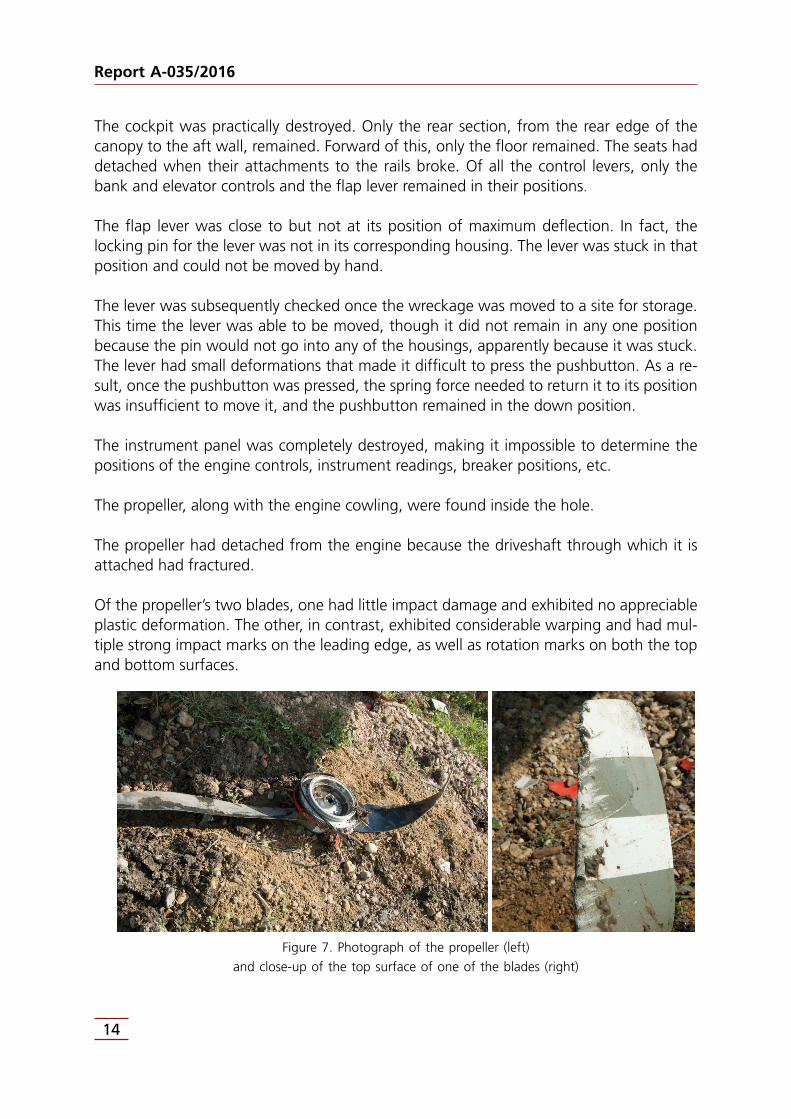
The propeller, along with the engine cowling, were found inside the hole.
The propeller had detached from the engine because the driveshaft through which it is attached had fractured.
Of the propeller’s two blades, one had little impact damage and exhibited no appreciable plastic deformation. The other, in contrast, exhibited considerable warping and had mul-tiple strong impact marks on the leading edge, as well as rotation marks on both the top and bottom surfaces.
Figure 7. Photograph of the propeller (left)
and close-up of the top surface of one of the blades (right)

Report A-035/2016
15
The engine was in the crop field, but very close to the trough. It had detached from the aircraft structure when its mount broke.
1.13. Medical and pathological information
Both aircraft occupants were killed when the trauma they sustained during the impact destroyed their vital organs.
The toxicological tests conducted did not detect the presence of ethyl alcohol or of any other toxic substance, narcotic or medications that could have played a role in the acci-dent.
1.14. Fire
There was no fire.
1.15. Survival aspects
The impact with the ground was extremely violent, causing the complete destruction of the front part of the aircraft, including the cockpit, on impact.
In light of the accident’s characteristics and the level of damage it caused to the aircraft, the occupants had virtually no chances of survival.
1.16. Tests and research
1.16.1. Eyewitness statements
1.16.1.1. Worker at the municipal pool
This employee was inside the complex that houses the Vegas del Condado municipal swimming pool, cleaning the pool.
He stated that he heard a small airplane fly over his position. He added that he heard the noise but did not see the airplane, since he continued with his work and did not look up.
A short time later he again heard the sound of the airplane, and this time he did look up. He watched as the airplane flew over the pool. It was flying very low, so much so that it brushed the top of a large cedar tree in the complex.

Report A-035/2016
16
He saw how as soon as it flew past the tree, the airplane banked right and plummeted immediately afterward, followed by the sound of the impact.
1.16.1.2. Resident in one of the houses
He was inside a house he owned that was located in the vicinity of the crash site.
At approximately 16:00 his step-daughter called him to tell him that her boyfriend was going to fly over the town and to look out the window to see if he could spot him.
He went outside and saw a small plane flying to the west, until it went out of sight beyond the house in the adjacent plot. He remembered feeling absolute silence, though he could not say if the engine had stopped or not, and then he heard a crash.
He went running to the location of the noise as he called 112.
He soon reached the crash site and saw the airplane wreckage.
1.17. Organizational and management information
The company TAFYR, S.A. was authorized by AESA to engage in aerial work involving oblique photography, surveillance and patrol activities. Its authorization was valid until 18 October 2017.
Point 8.1.1 Minimum altitudes of part A of its Operations Manual specifies that:
Aerial work flights shall be performed at visual heights (altitudes). The SERA2 regulation shall be observed at all times and in cities with a population of over 300,000, the require-ments specified in the applicable operational plans shall be observed.
In populated areas with under 300,000 inhabitants, the lowest altitude shall be 1000 ft above the highest obstacle.
In locations with more than 300,000 inhabitants, the operational flight plan filed by TAFYR and approved by AESA shall apply. The captain is responsible for complying with the re-quirements specified and approved by AESA in said operational flight plans.
In uninhabited areas, the lowest altitude shall be 500 ft AGL as per the SERA regulation. Operations below 500 ft are allowed with AESA approval.
2 Implementing Regulation (EU) No 932/2012, laying down the common rules of the air and operational provisions regarding services and procedures in air navigation.

Report A-035/2016
17
1.18. Additional information
Not applicable.
1.19. Useful or effective investigation techniques
1.19.1. Photographs taken during the accident flight
Investigators were able to recover the two photo cameras that were being used to per-form the aerial photographic work that constituted the purpose of the accident flight.
The memory cards were in good condition, allowing the information recorded in them to be extracted.
The downloaded data included four files associated with four photographs taken in the area of the accident shortly before the crash.
The metadata in the digital files for these photographs contain information on each, with data on sensor size, focal distance, time taken, etc.
Using these data, as well as the dimensions that certain elements have on the sensor and in reality and using optical and trigonometric principles, as well as photographic analysis techniques, the distance and height between the camera and a specific point when an image was taken was determined.
The diagram in Figure 2 shows the location where, based on the data indicated above, the photographs were taken. The height of each is as follows:
- Photograph 1: 73.38 m
- Photograph 2: 67.69 m
- Photograph 3: 113.13 m
- Photograph 4: 100.57 m
1.19.2. Synchronization of the times on the camera and the GPS unit
One photograph was selected that was taken during the circling maneuver flown over an industrial area in Villadongos del Páramo (León) prior to the accident, and the point from which the photograph was taken was identified.

Report A-035/2016
18
The GPS track for the flight was reviewed to determine the “GPS” time when the aircraft flew over the point from which the photograph was taken.
The metadata from the digital file for the photograph showed the “camera” time when the picture was taken.
The following results were obtained:
- “GPS” time: 14:01:49
- “Camera” time: 15:01:17
Therefore, the camera time was 59 minutes 28 seconds faster than the GPS time.
The last four photographs were taken at the “camera” times shown below, correspond-ing to the “GPS” times given:
Photograph number Camera time GPS time
4438 15:10:18 14:10:50
4439 15:10:19 14:10:51
4440 15:10:22 14:10:54
4441 15:10:26 14:10:58
It was noted that at the “GPS” times calculated from the camera time, the aircraft was approximately over the location from where the photographs were taken.

Report A-035/2016
19
2. ANALYSIS
2.1. Analysis of the tracks and possible impact sequence
As the information in point 1.12 shows, no evidence was found that the aircraft impacted any kind of object, either natural or artificial, prior to crashing into the ground. The crash itself left the longitudinal mark on the field that was found leading to the aircraft wreck-age.
There were also no aircraft fragments found separate from the main wreckage, which would indicate that no components detached from the aircraft prior to its impacting the ground.
The aircraft’s initial impact with the ground left a mark on the field measuring some 15 m in length. The aircraft components found inside this furrow were from the right wing.
This implies that when the aircraft impacted the ground, it was at a right bank angle. While it is difficult to quantify the aircraft’s bank angle, the pronounced verticality of the mark left by the wingtip indicates that the bank angle was severe.
After the initial contact, the right wing dug further into the ground, until a point was reached where structural damage was caused, as evidenced by the stringer fragment found inside this furrow.
The right wing’s contact with the ground in turn caused the aircraft to start to pivot about the outer edge of the wing, making the nose of the aircraft plunge to the ground (see Figure 8).
This was a high energy impact that caused the destruction of the front part of the air-frame and created the hole inside of which the engine and propeller were found.
The left wing then impacted the ground. Both the damage to this part of the aircraft and the marks left on the ground by this impact were considerably less significant than those produced by the previous impact. This implies that the initial impact absorbed most of the aircraft’s energy.
Figure 8. Aircraft impact sequence

Report A-035/2016
20
After the impact by the left wing, the aircraft was left with practically no speed, and its subsequent movement was limited to completing its pivot about the nose and the tail falling to the ground.
This all indicates that the aircraft approached the ground at a slow descent rate with a high right bank angle.
2.2. Analysis of the aircraft wreckage
The damage and deformations exhibited by the two propeller blades clearly indicate that when they impacted the ground, the engine was under power.
The elevator and rudder were both intact and in their positions. The elevator retained continuity to the control lever in the cockpit. This was not the case for the rudder, whose continuity was lost when its control cable was severed, almost in all likelihood during the impact with the ground.
Nothing was noted that would indicate the presence of a fault prior to the accident in any of the components involved in controlling the bank angle (ailerons, control stick or connecting cables).
The flaps were correctly attached to the wings and showed no signs of malfunctioning. The fracture of the control linkages is believed to have occurred solely as a result of the aircraft’s impact with the ground.
As for the position of the flaps at the time of the accident, it will be difficult to determine since the possibility of finding it out from the position of the flaps is ruled out by the fact that the control linkages were broken.
The lever used to actuate the flaps was in a position near “full flaps”, but with the locking pin outside the housing.
The pin and housings are designed so that the pin cannot leave the housing unless the pilot presses the release button. The fact that neither the pin nor any of the three housings present in the flap system exhibited any significant damage indicates that the pin did not leave the housing during, and as a result of, the impact, in which case the only possibility is that the pin was not in any of the housings.
The only time when the pin is not in one of the housings is when the lever is being moved from one fixed position of the flaps to another fixed position, either while being extended or retracted.

Report A-035/2016
21
It is likely, therefore, that at the time of the accident, the flap lever was being actuated by the pilot, though it is impossible to determine either its exact position or if the flaps were being lowered or raised.
2.3. Procedural analysis of the flight
According to the operations manual of the company TAFYR S.A., the company was au-thorized by AESA to do photographic work in populated areas with fewer than 300,000 inhabitants at an altitude of 1000 ft above the highest obstacle, and at 500 ft AGL in uninhabited areas. Operating below 500 ft required the company to obtain authorization from AESA prior to the flight.
The area over which the aircraft was flying moments before the accident may be regarded as being unpopulated; that is, it was not flying over a population center, but rather over a small group of houses, meaning that if the aircraft had had an engine failure, the pilot could have easily cleared the group of houses. The pilot should thus have maintained an altitude of no fewer than 500 ft AGL at all times.
However, based on the GPS data, the pilot descended below 500 ft (152.4 m) and main-tained an altitude that was considerably lower. The heights shown by the GPS at the various points range from 72 m at the start of the maneuver to 37 m at the last point. It is likely that because the subject of the photographic work was individuals who were relat-ed to the pilot, and due to the small size of the area to photograph, the pilot decided to descend in an effort to improve the quality of the photograph as much as possible. How-ever, flying at such a low altitude limited the pilot’s reaction time and prevented him from keeping an adequate margin of separation with the ground in the event of a problem.
2.4. Determining the aircraft’s flight path
Figure 2 shows two possible flight paths for the aircraft during the last phase of the flight. One was determined from GPS data and the other from the photographs taken from the aircraft and the marks and position of the wreckage after the accident.
As this graph shows, there are slight differences between the two trajectories.
The path obtained from the GPS information should be more accurate than the one de-termined from the photographs, given the methodology used to obtain the latter and the errors of the GPS system. In this regard, as specified in point 3.7.3.1.1.1 of ICAO Annex 10, the errors of the GPS SPS3 shall not exceed the following limits:
3 Standard positioning service. The specified level of positioning, velocity and timing accuracy that is available to any global positioning system (GPS) used on a continuous, worldwide basis.

Report A-035/2016
22
Worldwide average Worst location
95% of the time 95% of the time
Horizontal position error 9 m (30 ft) 17 m (56 ft)
Vertical position error 15 m (49 ft) 37 m (121 ft)
The GPS trajectory, however, does not seem to accurately reflect the aircraft’s position and heading at the time of the accident, as determined by the marks and the position of the wreckage, which are irrefutable, or by the statement of the eyewitness who was working at the pool.
This individual stated that he saw the aircraft, just once, fly overhead and that he then saw it bank right and fall. The GPS flight path shows that the aircraft flew over the pool upon reaching the area, then started circling the group of houses (not flying over the pool again, but close to it). The accident happened as it was completing the circling maneuver. All of this happened over a very short period of time, on the order of 20 seconds.
Given this scenario, it seems quite likely that what happened is that the eyewitness saw the aircraft fly overhead when it arrived in the area, that he then lost it from view during the few seconds that it was circling, and that he saw it again just before the accident. The short length of time that elapsed, combined with the fact that the eyewitness did not see any part of the circling maneuver, could have led him to think that the aircraft crashed immediately after he saw it arrive.
As concerns the inconsistencies observed involving the heading and position of the air-craft immediately before crashing to the ground, a few factors should be considered that could have affected the flight path.
The first is the position error in the GPS system, which, as indicated above, is between 9 and 17 m.
The accuracy of the GPS unit present in the aircraft is 49 ft.
Another consideration is the fact that the GPS unit does not record position data continu-ously, but rather in information packets. The data are stored in temporary storage (buffer) until the packet is complete, at which point it is sent to the memory, where the informa-tion is recorded.
When the unit is turned off suddenly, as must have happened in this case, the data that are in the buffer are not sent to the memory and are irretrievably lost. Experience from previous cases has shown that this period of time lasts from 2 to 4 seconds.

Report A-035/2016
23
Considering the position errors, the accuracy of the unit and the fact that the GPS data for the last part of the flight were lost, it is believed that the aircraft’s actual flight path was fairly close to the GPS path shown in Figure 2, though slightly shifted to the northwest. The final part, for which there are no GPS data, would have matched the flight path cal-culated from the photographs.
In addition, a comparison of the flight path obtained from the GPS data with the location of the points from which the photographs were determined to have been taken shows that the approach used to obtain the latter would be sufficient to allow for an acceptably accurate analysis of the flight path.
2.5. Analysis of the circling maneuver
During the accident flight, the crew conducted a total of four photography sessions, in-cluding the one at the accident site. The table below provides a summary of the average values of the turn radius and heights of the circling maneuvers.
Location Turn radius (m) Height (ft)
Narón 350 500
Cedeira 300 400 to 600
Villadangos 400 600
Villanueva del Condado 150 230
A comparison of these parameters shows that those for the first three circling maneuvers are rather uniform both in terms of the turn radius and the height at which the airplane was flying. The parameters for the circling maneuver that led to the accident, however, are signifi-cantly lower (4th line in the above table).
The smaller the turn radius, the higher the aircraft’s bank angle has to be in order to execute the turn.
The bank angle can be obtained from the angular velocity, which can in turn be calculated from the turn angle and the duration of the turn.
Figure 9. Sectors created from points of last circling
maneuver. Radius and angle spanned by each sector

Report A-035/2016
24
Figure 9 shows the final 9 points of the turn, though point 1 will not be used. Each point is separated by 2 s.
These points are grouped by threes, 2-3-4, 3-4-5, 4-5-6, etc., to form sectors. The center of the circle that passes through all three points in each group was calculated and used to determine the radius and angle that comprise the sector.
These data were used to calculate the angular velocity of the airplane in each sector, and this value was then used to calculate the aircraft’s bank angle and linear velocity. The table below shows the resulting values.
Sector Radius(m)
Sector angle Angular speed(rad/s)
Linear speed(m/s) (kt)
Bank angle
2-3-4 159,8 65,2º 2,8448 10-1 45,46 88,37 52,81º
3-4-5 111,3 92,0º 4,0142 10-1 44,68 86,85 61,32º
4-5-6 201,4 50,4º 2,1991 10-1 44,29 86,09 44,79º
5-6-7 103,6 98,6º 4,3022 10-1 44,57 86,64 62,90º
6-7-8 133,2 75,0º 3,2729 10-1 43,59 84,73 55,49º
7-8-9 119,4 78,6º 3,4295 10-1 40,94 79,58 55,06º
In the last segment of the turn, the aircraft had a bank angle of 55.06º and a speed of 79.6 kt.
Point 1.6.2 contains information on the aircraft’s stall speed in terms of the bank angle and the position of the flaps. Since the Aircraft Flight Manual only provides information on the stall speeds for three bank angles (0º, 30º and 60º), the values for 60º will be used for reference, as it is the closest to the bank angle that the airplane had.
The stall speed at a 60º bank angle is 80 kt with the flaps up, 75 kt with flaps 1 and 72 kt with full flaps. Based on the calculations done, the aircraft’s speed during the final segment was below the no-flap stall speed, though it was above the flaps-1 stall speed.
On this topic, it should be noted that the aircraft speeds calculated were ground speeds, and that the stall speeds given in the flight manual are airspeeds.
Therefore, the speeds calculated for the aircraft have to be corrected for the wind present at the time, the value of which is unknown. In any case, the effect of the wind will make the airspeed be higher than the ground speed when the wind comes at the aircraft from the front, and lower when it comes at the aircraft from the tail.
Although the wind is estimated to have been weak, since the aircraft was so close to its stall speed, the wind could have contributed to the airplane approaching its stall speed.

Report A-035/2016
25
It is also worth noting that the aircraft was descending as it circled. As commented in point 1.11.1, at the start of the maneuver (point 2), it was at an altitude of 922 m, a value that decreased gradually to 895 m by the time it reached the last point. This means that it descended 27 m over a time period of 14 s, equivalent to an average descent rate of 115.7 m/min (380 ft/min).
At this last point, the aircraft’s AGL was only about 37 m, meaning it could not descend any more. For this reason, the pilot probably made control inputs to halt the aircraft’s des-cent. One effect associated with this action is an increase in drag that, if not offset by an increase in power, leads to a loss of speed.
2.6. Stall in a turn
The analysis of the marks and the aircraft wreckage, as well as of the speeds obtained from the data extracted from the GPS, the information on the turn angle and the analysis of the circling maneuver are consistent with a stall in a turn situation.
Normally this maneuver is executed at a safe altitude. While recovering from such a stall, the airplane loses approximately 500 ft.
In this case the pilot was not high enough above the ground to recover from the stall, which resulted in the aircraft impacting the ground, first with the wingtip, followed by the rest of the aircraft.


Report A-035/2016
27
3. CONCLUSIONS
3.1. Findings
• The pilot had a commercial pilot license along with SEP, MEP, IR and FI PPL SEP ratings, all of them valid.
• He had a class-1 medical certificate that was valid until 31 May 2017.
• The pilot was sufficiently experienced in flying aircraft in general, the accident aircraft type in particular, and in doing aerial photography work.
• The aircraft’s documentation was valid and it was airworthy.
• The company that operated the aircraft, TAFYR, had the necessary permits to conduct the aerial photography work that was planned for the accident flight.
• The aircraft was refueled with 110 liters of AVGAS 100LL fuel before starting the flight.
• The aircraft had a range of 7 hours.
• The aircraft took off from the A Coruña Airport at 14:39.
• After takeoff, it flew for 1 h 32 min before the accident, during which time it circled over three different locations to take aerial photographs.
• The average turn radius of these circles was 350 m, and their average height was 500 ft.
• The aircraft started a turn over a group of houses in Villanueva del Condado (León), one of which belonged to a relative of the pilot.
• The average radius of this turn was 150 m and its average height was 230 ft.
• During this turn, the aircraft reached bank angles of over 60º.
• The aircraft impacted the terrain at a high right bank angle.
• At the time of the accident, the engine was under power.
• There were no signs that the aircraft’s control systems were faulty or malfunctioned.
• It was not possible to determine the position of the flaps at the time of the accident.

Report A-035/2016
28
3.2. Causes/Contributing factors
The accident occurred as the aircraft stalled while circling over a group of houses the oc-cupants wanted to photograph
The following factors contributed to the accident:
• The low circling altitude.
• Circling the group of houses with such a small turn radius, which required an excessive bank angle.

Report A-035/2016
29
4. SAFETY RECOMMENDATIONS
No safety recommendations are issued.
