ccc class i modeling report - nc
TRANSCRIPT
PROPOSED CAROLINAS CEMENT COMPANY LLC CASTLE HAYNE, NORTH CAROLINA PLANT -
CCLL AASSSS II AAII RR DDII SSPPEERRSSII OONN MM OODDEELL II NNGG
Prepared for:
Carolinas Cement Company LLC Castle Hayne, North Carolina Plant
Prepared by:
Alpine Geophysics, LLC 2655 South County Road 750 East
Dillsboro, Indiana 47018 Project No. TS-311
Environmental Quality Management, Inc.
Cedar Terrace Office Park, Suite 250 3325 Durham-Chapel Hill Boulevard
Durham, North Carolina 27707 PN 050020.0051
February 25, 2008

ii
TABLE OF CONTENTS Section Page Figures............................................................................................................................................ iii Tables............................................................................................................................................. iv Executive Summary....................................................................................................................... vi 1 Site Description....................................................................................................................1 2 CCC Sources and Emissions................................................................................................4 3 Class I Air Quality Modeling Methodology ........................................................................7 3.1 Class I Impact Analysis Overview...........................................................................7 3.2 Regulatory Context and Model Selection ................................................................8 3.3 CALPUFF Modeling System Overview ..................................................................9 3.4 Modeling Domain and Receptor Grid....................................................................11 3.5 Meteorological Data...............................................................................................11 3.6 Geophysical Data ...................................................................................................13 3.7 CALPUFF Model Options and Configuration.......................................................13 3.8 Class I Modeling Analysis .....................................................................................15 3.9 Documentation.......................................................................................................16 4 Class I Modeling Results ...................................................................................................17 4.1 Class I SIL..............................................................................................................17 4.2 Visibility Analysis..................................................................................................17 4.3 Class I Deposition Analysis ...................................................................................24 References......................................................................................................................................26

iii
FIGURES
Number Page 1 General Location of CCC Plant ...........................................................................................2 2 Existing Site Layout.............................................................................................................3 3 CALPUFF Modeling Schematic (Scire, et al., 2000) ........................................................10 4 4-km CALPUFF Modeling Domain Within 12-km Eastern US........................................12 5 4-km CALPUFF Modeling Domain ..................................................................................12

iv
TABLES
Number Page 1 Main Kiln Stack Parameters for the CCC Plant...................................................................4 2 Emission Increases for the CCC Plant .................................................................................6 3 Size Distribution of Particulate Matter for the Main Kiln Stack (E44) .............................14 4 PSD Class I Significant Impact Levels ..............................................................................15
5 Summary of Sulfur Dioxide Class I Significant Impacts at Cape Romain National Wildlife Refuge Due to Proposed CCC Plant....................................................................18
6 Summary of Sulfur Dioxide Class I Significant Impacts at Swanquarter National Wildlife Refuge Due to Proposed CCC Plant....................................................................18
7 Summary of Nitrogen Oxides Class I Significant Impacts at Cape Romain National
Wildlife Refuge Due to Proposed CCC Plant....................................................................19
8 Summary of Nitrogen Oxides Class I Significant Impacts at Swanquarter National Wildlife Refuge Due to Proposed CCC Plant....................................................................19
9 Summary of PM10 Class I Significant Impacts at Cape Romain National Wildlife Refuge Due to Proposed CCC Plant ..................................................................................20
10 Summary of PM10 Class I Significant Impacts at Swanquarter National Wildlife Refuge Due to Proposed CCC Plant ..................................................................................20
11 Class I Area Visibility Impairment Analysis at Cape Romain National Wildlife Refuge
Due to Proposed CCC Plant – Maximum Percent Change in Extinction Coefficient and Number of Days > 5% (MVISBK=2) ................................................................................22
12 Class I Area Visibility Impairment Analysis at Swanquarter National Wildlife Refuge
Due to Proposed CCC Plant – Maximum Percent Change in Extinction Coefficient and Number of Days > 5% (MVISBK=2) ................................................................................22

v
TABLES (continued)
Number Page
13 Class I Area Visibility Impairment Analysis at Cape Romain National Wildlife Refuge Due to Proposed CCC Plant – Maximum Percent Change in Extinction Coefficient and Number of Days > 5% (MVISBK=2) ......................................................23
14 Class I Area Visibility Impairment Analysis at Swanquarter National Wildlife Refuge Due to Proposed CCC Plant – Maximum Percent Change in Extinction Coefficient and Number of Days > 5% (MVISBK=6) ................................................................................23 15 Sulfate/Nitrate Deposition at Cape Romain National Wildlife Refuge Due to Proposed CCC Plant ..........................................................................................................................24 16 Sulfate/Nitrate Deposition at Swanquarter National Wildlife Refuge Due to Proposed
CCC Plant ..........................................................................................................................25

vi
EXECUTIVE SUMMARY
This document provides the results of the Class I area air quality modeling analysis
required as part of the Prevention of Significant Deterioration (PSD) submittal for the proposed
Carolinas Cement Company LLC (CCC) plant to be located near Castle Hayne, North Carolina.
CCC is proposing the construction of a new Portland cement manufacturing plant. This
document includes an evaluation of two specific Class I areas in terms of PSD related air quality
impacts due to the proposed CCC facility including: Significant Impact Levels (SILs) and
associated Significant Impact Area (SIA); Class I PSD increment consumption; Class I area
visibility impacts; and Class I sulfate/nitrate deposition rates. Dispersion modeling was the
primary modeling tool used to assess the Class I area impacts for pollutant emissions from the
proposed new sources at CCC. Incremental concentration, deposition, and visibility impact
estimates were compared to ambient air levels recommended or specified by the Federal Land
Managers (FLM), the North Carolina Department of Environment and Natural Resources
(DENR), and the U. S. Environmental Protection Agency.
The Class I area analysis focused on the two closest Class I areas, namely, Swanquarter
National Wildlife Refuge, located about 170 km to the northeast of the proposed CCC site along
the north shore of the Pamlico Sound, east and west of the village of Swan Quarter, and the Cape
Romain National Wildlife Refuge located about 220 km to the southwest of the proposed CCC
site just northeast of Charleston, South Carolina. The Class I impacts were determined using the
CALPUFF methodology as recommended by the FLM. A modeling protocol was submitted to
Ms. Meredith Bond and Ms. Jill Webster of the Air Quality Branch of the U.S. Fish and Wildlife
Service (USFWS), and to DENR. Both the USFWS and DENR approved the modeling protocol
after CCC agreed to a few modifications which were subsequently incorporated herein.
All modeling was performed using a refined grid modeling approach (4 km grid and
meteorological data base) in the CALPUFF modeling system. Based on this dispersion,
deposition, and visibility modeling, the ambient air impacts of the project were estimated to be
less than all threshold levels specified by all applicable regulatory requirements for both the
Swanquarter and Cape Romain National Wildlife Refuge Class I areas.

1
SECTION 1
SITE DESCRIPTION
Figure 1 shows the general location of the proposed plant. Figure 2 presents a closer
view of the proposed CCC site including existing roads and plant buildings. The buildings
currently located on this site were from the previously active Ideal Cement facility. CCC
currently utilizes some of the silos on site for storage and shipping/receiving operations as part of
their permitted cement terminal operations. The proposed facility will be newly constructed
equipment and structures with some existing structures being reused where feasible. The
geographical setting around the plant is flat to gently rolling with very few significant elevated
terrain features. The Cape Fear River bounds the property to the north and flows south through
Wilmington, NC. The river valley does not create much of a terrain change from the surrounding
topography. Terrain along the Atlantic Coastal Plain, which dominates nearly all of the
geographical setting between the proposed site and the Swanquarter and the Cape Romain
National Wildlife Refuges, is generally flat to gently rolling to the coast. The area is
characterized by small farms, small towns, pine forests, and sparsely populated rural residential
areas. The town of Castle Hayne lies less than three miles to the southwest and has a population
of less than 1200.

2
Figure 1. General Location of CCC Plant

3
Figure 2. Existing Site Layout
4
SECTION 2
CCC SOURCES AND EMISSIONS
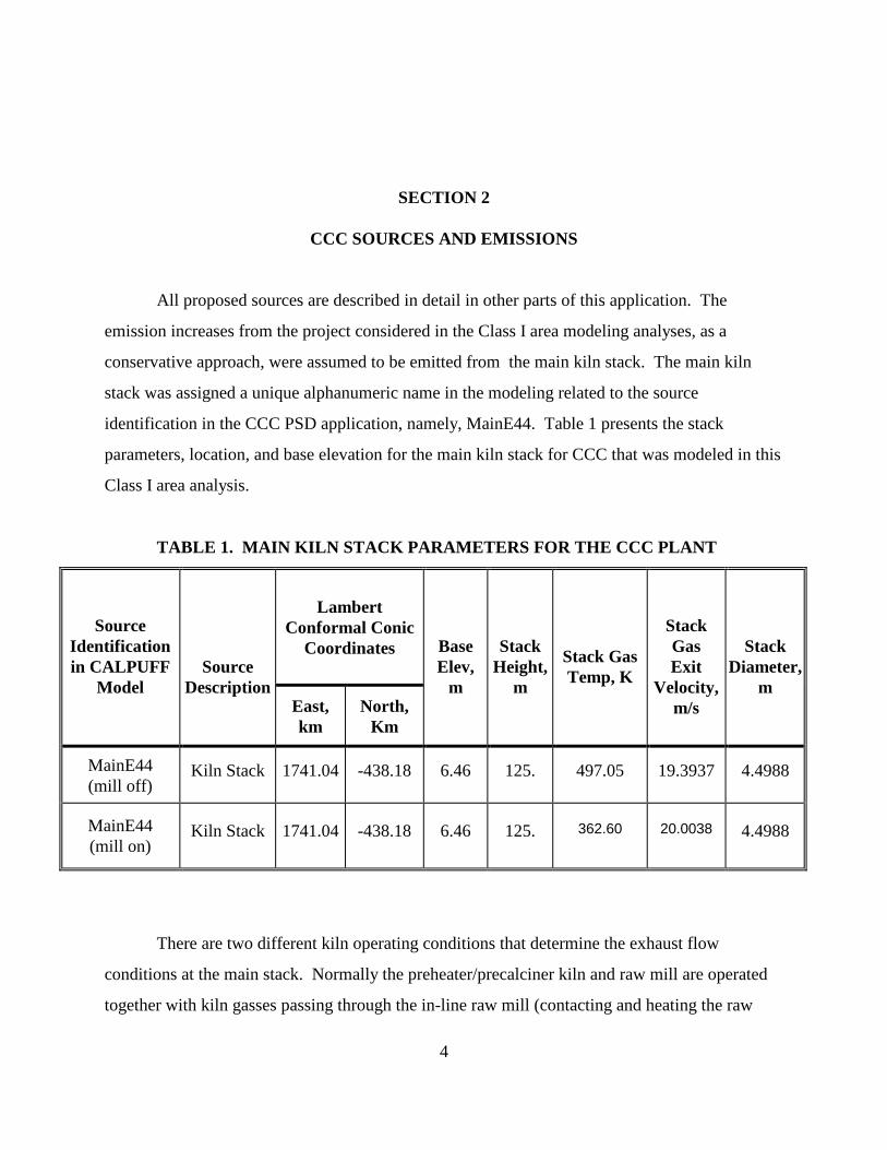
All proposed sources are described in detail in other parts of this application. The
emission increases from the project considered in the Class I area modeling analyses, as a
conservative approach, were assumed to be emitted from the main kiln stack. The main kiln
stack was assigned a unique alphanumeric name in the modeling related to the source
identification in the CCC PSD application, namely, MainE44. Table 1 presents the stack
parameters, location, and base elevation for the main kiln stack for CCC that was modeled in this
Class I area analysis.
TABLE 1. MAIN KILN STACK PARAMETERS FOR THE CCC PL ANT
Lambert
Conformal Conic Coordinates
Source Identification in CALPUFF
Model
Source Description
East, km
North, Km
Base Elev,
m
Stack
Height, m
Stack Gas Temp, K
Stack Gas Exit
Velocity, m/s
Stack
Diameter, m
MainE44 (mill off)
Kiln Stack 1741.04 -438.18 6.46 125. 497.05 19.3937 4.4988
MainE44 (mill on)
Kiln Stack 1741.04 -438.18 6.46 125.
362.60
20.0038
4.4988
There are two different kiln operating conditions that determine the exhaust flow
conditions at the main stack. Normally the preheater/precalciner kiln and raw mill are operated
together with kiln gasses passing through the in-line raw mill (contacting and heating the raw

5
material as it is ground) before exiting the baghouse and main stack. The kiln system is operated
with the “mill on” condition approximately 90 percent of the time.
When the raw mill is not operating (“mill off” condition, approximately 10 percent of the
time), kiln system exhaust gasses bypass the raw mill and are directly exhausted through the
baghouse and main stack. This is a short-term condition that normally occurs only a few hours at
a time because the raw mill must operate to produce kiln feed (once the feed is depleted from
storage, the kiln must shut down). The stack gas exhaust temperature is significantly higher
during this condition because heat is not being transferred to the raw material. The actual stack
exhaust flow rate is only slightly higher during the mill off condition due to the addition of
conditioning water to cool the gases.
Stack emission rates for most pollutants are not affected by the two different kiln
operating conditions. However, maximum SO2 emissions will occur with the mill off condition
because SO2 is absorbed in the raw mill, only when it is operating. When the raw mill is
operating, the actual SO2 emission rate is less than the annual average SO2 emission rate.
For the Class I modeling, long-term (annual) emissions are modeled using the annual
emission rates for each pollutant and the mill on stack exhaust conditions representing the typical
long-term kiln operations. Short-term (24-hours or less) emissions are modeled using two
scenarios to evaluate worst-case conditions: 1) mill on stack exhaust with average SO2 emission
rate and maximum PM10 and NOX emission rates, and 2) mill off stack exhaust with maximum
SO2, PM10, and NOX emission rates.
Table 2 presents the increased emissions due to the proposed CCC facility that were used
in all Class I area modeling. The Table 2 emissions were modeled for all SIL impacts as well as
visibility and deposition impacts at both Swanquarter and Cape Romain. The maximum
emission rates were used in all short-term modeling and the annual average rates for annual
modeling (except the annual PM10 modeling where the maximum rate was also used). As
indicated in Section 4 of this report, no Class I SILs were exceeded and thus, no further
increment modeling including other sources was required.

6
TABLE 2. EMISSION INCREASES FOR THE CCC PLANT
SO2 Emissions, lb/h
NOx Emissions, lb/h
PM10 Emissions, lb/h
Source
Identification in CALPUFF
Model
Source Description Max ratea
Average rateb
Max ratea Average
rateb Max ratea
Average rateb
MainE44 Kiln Stack
450.40
247.52
498.61
488.13
122.88
122.23
aBased on maximum short term emissions for Kiln Stack E44 with mill off condition. bBased on average emissions for Kiln Stack E44 which are the total for a year based on proposed throughputs and the maximum number of hours in a year, 8760.

7
SECTION 3
CLASS I AIR QUALITY MODELING METHODOLOGY
3.1 Class I Impact Analysis Overview
As noted above, the Class I areas analyzed in this report are the Swanquarter National
Wildlife Refuge, located along the north shore of the Pamlico Sound, east and west of the village
of Swan Quarter, North Carolina and the Cape Romain National Wildlife Refuge, located
northeast of Charleston, South Carolina. Based on the July 26, 2007 pre-application meeting
with DENR (Mr. Chuck Buckler) and a subsequent teleconference meeting on August 21, 2007
with USFWS and DENR representatives, other more distant Class I areas were not considered in
this analysis. These exclusions were based on the distances between CCC’s site and other Class I
areas being greater than 300km. The modeling for the Class I areas included an analysis of the
SIL thresholds for SO2, NOx, and PM10 and impacts of the proposed facility on other Air Quality
Related Values (AQRVs). No Class I increment consumption analysis was conducted because
the impacts of the proposed facility alone were less than the applicable SILs (see Section 4).
The modeling for the Class I areas was performed with the CALPUFF Model (Version
5.8, recently approved by the EPA for PSD analyses) and its various companion programs. The
CALPUFF modeling system has been adopted by the EPA as a guideline model for source-
receptor distances greater than 50 km. CALPUFF was recommended for Class I impact
assessments by the FLM Workgroup (FLAG, 2000), by the Interagency Workgroup on Air
Quality Modeling (IWAQM) (EPA, 1998), by VISTAS (VISTAS, 2005) for visibility modeling
required under the Best Available Retrofit Technology (BART) program, and by the EPA for
PSD modeling at Class I areas. As recommended, CALPUFF was used as the primary modeling
system for the refined source-specific modeling applications for the subject Class I areas. The
model’s formulation provides the appropriate tools for assessing and simulating the various
geographical and meteorological influences, the stack and stack gas conditions, the atmospheric

8
and physical processes and the gas-phase, aerosol, and aqueous-phase chemical processes that
influence ambient air concentrations, deposition, and visibility.
The CALPUFF modeling system was originally developed as a component of a three-part
modeling system sponsored by the California Air Resources Board (CARB) in the mid-1980s.
The CARB sought to develop a new puff-based model, a new grid-based model and an improved
meteorological processor that would support application of the two. CALGRID was the urban-
scale photochemical grid model resulting from the project (Yamartino et al., 1992) comparable in
science and capabilities to the Urban Airshed Model (UAM-IV) (Scheffe and Morris, 1993). The
model formulation was aimed at overcoming the deficiencies in EPA’s steady-state Gaussian
plume models that were routinely used for inert and linearly reactive materials (principally SO2)
from elevated point sources. Thus, the CALGRID model was designed to treat the complexities
of urban-scale photochemical processes while CALPUFF was formulated to treat the non-steady
state transport, diffusion, linear reaction, and deposition of primary pollutants from point sources.
3.2 Regulatory Context and Model Selection
The proposed CCC site is in attainment with all ambient air quality standards. The
proposed plant is subject to the air dispersion modeling requirements associated with the PSD
permitting program. The EPA Guideline on Air Quality Models (40 CFR 51 Appendix W) and
the New Source Review Workshop Manual (EPA, 1990) offer preferred techniques for
performing air dispersion modeling. Additional modeling recommendations are provided in the
Interagency Workgroup on Air Quality Modeling (IWAQM) Phase II Summary Report and
Recommendations for Modeling Long Range Transport Impacts (EPA, 1998) and in the Federal
Land Managers’ Air Quality Related Values Workgroup (FLAG) Phase I Report (FLM, 2000).
Recommendations from these documents were used to develop this air modeling methodology.
Air dispersion modeling evaluations required for a Class I area under the requirements for
PSD analysis include a SIL analysis, PSD increment evaluation (if SIL’s are exceeded), visibility
impairment evaluation through the calculation of extinction coefficients, and deposition impacts.
Given the potential complex nature of the meteorology in a near shoreline environment (along
the eastern edge of the Atlantic Coastal Plain) and the recommendations of the various regulatory
agencies, the CALPUFF Model was used for performing all of the Class I air dispersion

9
modeling for this project. The application of CALPUFF to this project in a refined mode was
performed using the CALMET program (Version 5.8) along with detailed gridded meteorology
(4km grid spacing) based on hourly and spatially consistent meteorological data sets generated
using the MM5 program along with observed NWS data. This is consistent with the
aforementioned recommendations and guidelines. The CALPOST and POSTUTIL post-
processors were used to calculate the visibility extinction coefficients, the concentrations in the
SIL and PSD increment averaging times, and the deposition rates from the CALPUFF
concentrations and deposition rates.
3.3 CALPUFF Modeling System Overview
CALPUFF is a non-steady state numerical air quality model that simulates the transport,
diffusion, deposition, and chemical transformation of SO2, NOx, and particulate emissions from
point, line, and area sources. Emissions are characterized by diffusing puffs that are transported
by the wind and within which chemical reactions are simulated. The main components of the
model are CALMET (a three-dimensional kinematic meteorological interpolator), CALPUFF
(the core dispersion and chemical transformation module), and CALPOST (a post-processing
package). Figure 3 (original Figure 5 from the CALPUFF User’s Guide, Scire et al, 2000) shows
a flow diagram of the model. In all cases, the Linux operating system version of CALPUFF,
Version 5.8 was used in this study.
The CALMET meteorological processor was used with meteorological, geophysical, land
use, and elevation data to generate hourly, gridded meteorological inputs for the modeling study.
Final generated meteorological data sets consisted of three years (2001-2003) of 4-km grid
resolution data using MM5 data sets as the initial guess field supplemented with observed
National Weather Service surface and upper air sounding observations within the study area.
Terrain, land use, and land cover data were based on USGS data. All meteorological data were
based on a 4-km gridded modeling domain generated in the CALMET Version 5.8 format by the
USFWS in association with VISTAS. The data used in this analysis extend well beyond each
Class I area (>100 km) and encompass a large enough area to allow the genesis of mesoscale
meteorological events as well as incorporate all other PSD sources if applicable.

10
Figure 3. CALPUFF Modeling Schematic (Scire, et al., 2000)
The CALPUFF Model contains the algorithms for determining the transport and dispersion
of emissions into modeling grids at time steps commensurate with meteorology and puff
tracking. To perform the most representative analysis as possible of the proposed CCC project,
the modeling study followed all applicable regulatory guidelines.
Post-processors were used subsequent to the application of the CALPUFF Model which
only calculates the hourly receptor specific air concentrations. CALPOST and POSTUTIL were
used to generate air concentrations on an individual pollutant and averaging period basis. The
processors were also used to estimate visibility impairment and deposition impacts. POSTUTIL
was used for the repartitioning of the pollutant-specific deposition rates and for combining
particle size contributions. CALPOST was used to obtain SIL-applicable results and PSD
increment consumption, calculate the light-extinction coefficient changes, and estimate the total
annual sulfur and nitrogen deposition at each Class I area.

11
3.4 Modeling Domain and Receptor Grid
The computational modeling domain and receptor grid serve as the basis for all modeling
that were performed. The domain represents the extent of the study area and the modeling grid
provides a consistent format for conducting the modeling and for translating the meteorology
data to the computation level.
The modeling domain for this analysis was selected by using an approximate 200 km buffer
around the CCC site and a 100 km buffer around both the Swanquarter and Cape Romain Class I
areas. This buffer allowed representative upwind generation of meteorological data for consideration
of plume transport and dispersion in the vicinity of the coastline regions.
The computational grid was a Lambert Conformal Coordinates (LCC) grid with a
projection origin of 40oN and 97oW and matching parallel latitudes of 33o and 45o. The grid has
4-km grid cell spacing using a Datum of NWS84 which gives an origin of 1066.005km and
-686.004km. The domain consists of 228 x-coordinates and 232 y-coordinates. Figure 4 shows
the overall 4-km modeling domain (Subdomain 5 in VISTAS vernacular) within the overall 12-
km Eastern U.S. domain and Figure 5 shows the 4-km domain with the location of the CCC
plant, Swanquarter and Cape Romain indicated.
The Class I area receptor locations were taken from the National Park Service (NPS) Class I
receptor database (http://www2.nature.nps.gov/air/Maps/Receptors/index.cfm). These locations
were projected into the appropriate computational grid, and reformatted for input into CALPUFF.
Elevations for each receptor were determined from digital elevation data from the NPS information.
3.5 Meteorological Data
All meteorological data were generated for the modeling domain at a 4-km grid scale.
The data were obtained from DENR and consisted of processed MM5 data and NWS
observations using the CALMET, Version 5.8 format. These data were generated through
VISTAS for 2001, 2002, and 2003. The 12-km EPA MM5 national data bases for 2001 and
2002 and the 36 km MM5 national data base for the 2003 period were used as the initial guess
fields for each year, respectively along with the NWS observations to provide fine local detail
and refinement.

12
Figure 4. 4-km CALPUFF Modeling Domain Within 12-km Eastern US
Figure 5. 4-km CALPUFF Modeling Domain

13
3.6 Geophysical Data
The CALMET processor was used by VISTAS along with geophysical, land use, and
elevation data to generate meteorological inputs for the modeling study. Land use and land
cover data were derived from the 1:250,000-scale United States Geological Survey (USGS)
Composite Theme Grid (CTG) data (ftp://edcftp.cr.usgs.gov/pub/data/LULC/250K). Class I
terrain elevation data were obtained from the NPS Class I area data base.
3.7 CALPUFF Model Options and Configuration
The CALPUFF modeling parameters adhered to DENR, US EPA, and FLM guidance
documents. A brief discussion of several key inputs used in the modeling is provided below.
Specification of Background Rayleigh Scattering
This option is applicable to the visibility calculations. Rayleigh scattering refers to the
scattering of light off of the molecules of the air. Natural atmospheric light extinction due to
Rayleigh scattering can create variations in background visibility. The FLAG guidance
document recommends a specific value of 10 Mm-1 which was derived and applicable at 5000 ft
Mean Sea Level (MSL). An elevation-dependent Rayleigh term based on receptor elevations in
Swanquarter and Cape Romain could potentially affect the calculation of visibility impacts. The
factor of 10 Mm-1 was used as a conservative measure for this study.
Humidity
The study used a maximum 95 percent relative humidity as recommended by the USFWS
(Bond, 2007). The background light extinction was computed first using the FLAG (FLAG,
2000) recommended refined method in CALPUFF, where MVISBK = 2. In this method
extinction was calculated as a function of speciated Particulate Matter (PM) concentrations (from
the CALPUFF Model) and hourly relative humidity values from the hourly 4-km meteorological
data. The background light extinction was computed a second manner using the FLAG (Allen,
2006) recommended method in CALPUFF where MVISBK = 6. In this method extinction is
calculated as a function of speciated PM concentrations (from the CALPUFF Model) and

14
average quarterly default relative humidity values from the FLAG guidance document for the
Swanquarter and Cape Romain Class I areas, namely:
Swanquarter: Winter – 2.9 Spring – 3.3 Summer – 3.8 Fall – 3.2
Cape Romain: Winter – 2.9 Spring – 3.3 Summer – 3.9 Fall – 3.3
Particulate Matter Speciation
Very limited data are available on the species and size distribution of PM emissions from
cement kilns. For modeling purposes, AP-42 Table 11.6-5, Summary of Average Particle Size
Distribution for Portland Cement Kilns, (EPA, 1995) for a dry process with a fabric filter (SCC
3-05-006-06) was used as the basis for the particle size distribution for particulate emissions.
Table 3 provides the PM size distribution by size category that was used in the CALPUFF
Model. The mass distribution of all PM was adjusted for only PM10 by weighting the distribution
only for PM10. The percent in each particle size category was then used to distribute the
emissions. PM10 emission estimates included condensibles.
TABLE 3. SIZE DISTRIBUTION OF PARTICULATE MATTER F OR THE MAIN KILN STACK (E44)
Particle Size Range (µµµµm)
Source ID and
Description Low High
Mean particle
diameter, (µµµµm)
Filterable PM (%)
Filterable & Condensible
PM10 (%)
Maximum short-term emissions for SIL
modeling, lb/h
15 20 17.1 14.3 - -
10 15 12.3 6.5 - -
5 10 7.6 7.2 6.1 7.51
2.5 5 3.8 32.8 27.9 34.33
0.5 2.5 1.7 39.2 66.0 81.04
Main E44
Total 100 100.0 122.88

15
3.8 Class I Modeling Analysis
For the visibility and deposition analyses, the recommendations in the Interagency
Workgroup on Air Quality Modeling (IWAQM) Phase II Summary Report and Recommendations
for Modeling Long Range Transport Impacts (EPA-454/R-98-019, December 1998) and the
Federal Land Managers’ Air Quality Related Values Workgroup (FLAG) Phase I Report (U.S.
Forest Service- Air Quality Program, the NPS – Air Resources Division, and the USFWS – Air
Quality Branch, December 2000) were followed.
The SILs specified by the PSD regulations for Class I areas were used to discern the
extent of the potential significant impact areas. Table 4 summarizes the Class I significant
impact levels for this analysis.
TABLE 4. PSD CLASS I SIGNIFICANT IMPACT LEVELS
Averaging Period SO2
(µg/m3) NOx
(µg/m3) PM10
(µg/m3) Annual 0.1 0.1 0.2
24 Hour 0.2 0.3
3 Hour 1
The visibility analysis evaluated the potential change in light extinction relative to the
natural background due to the proposed project. The analysis computed the light extinction on a
daily (24-hour block) basis for all receptors located in the NPS receptors for Swanquarter and
Cape Romain. The CALPUFF modeling resulted in the calculation of ground-level air
concentrations of visibility impairing air emissions including sulfates, nitrates, and PM. These
results were converted to light-extinction coefficients using the equations in the IWAQM (EPA,
1998) and FLAG guidance (FLM, 2000). All of the recommended light extinction procedures
are part of the POSTUTIL and CALPOST post-processor analyses.
The calculations include a determination of the natural background extinction, which is a
function of naturally occurring atmospheric pollutants as well as Rayleigh scattering. The
background extinction coefficients were calculated using the methodology in Appendix 2.B –

16
Estimate of Natural Conditions (FLM, 2000). The analyses were based on 24-hour averages of
visibility as recommended by the FLAG guidance.
The threshold level specified in the IWAQM and FLAG guidance whereby the source
impacts on visibility are acceptable is a maximum 5 percent (5%) change in light extinction over
the background level on each day (natural background varies by day considering relative
humidity, location, and the like). When applying the average relative humidity in method
MVISBK=6, the 98th percentile value light extinction on an annual basis (8th highest value) and
over the three years of analysis (22nd highest value) was compared to the 5 percent threshold.
Guidance from the FLAG document was used for performing the Class I area sulfate and
nitrate deposition modeling analysis. Annual deposition values for each Class I area were compared
to the Deposition Analysis Threshold (DAT) for sulfur and nitrogen deposition as specified in a letter
from the NPS and the USFWS (to Mr. S. Becker, Executive Director of STAPPA/ALAPCO, January
2, 2002) and as presented in the associated Guidance on Nitrogen And Sulfur Deposition Analysis
Thresholds (downloaded from the FLM website at
www2.nature.nps.gov/air/permits/flag/flaginfo.index.htm). The applicable DAT proposed by the
Guidance is 0.01 kg/ha/yr for both sulfate and nitrate deposition.
3.9 Documentation
All input, output, and intermediate files used in the modeling in CALPUFF and all post-
processors will be provided on storable computer diskettes to DENR and to the USFWS. The
CALMET meteorological data files for 2001, 2002, and 2003 were provided by DENR (courtesy
of VISTAS and USFWS) and therefore, do not need to be resent.

17
SECTION 4
CLASS I MODELING RESULTS
4.1 Class I SIL
Tables 5 through 10 present the maximum impacts on both the Cape Romain and
Swanquarter Class I areas for each year of meteorological analysis for SO2, NOx, and PM10.
Where applicable, ambient air concentration impacts for both the “mill off” and “mill on”
operations are presented. Generally, the “mill on” operations resulted in lower concentration
estimates than those during a “mill off” condition as applicable to short-term averaging periods.
As can be seen, the air quality impacts are less than the Class I SILs for SO2, PM10 and NOx for
all averaging periods for all operational conditions of the mill. Therefore, no further analysis was
required in terms of PSD increment consumption for the proposed facility or for any cumulative
impacts with other sources in the region.
4.2 Visibility Analysis
The revised EPA guidance (IWAQM, 1998) and the FLM guidance (FLAG, 2000)
recommends the use of non-steady state dispersion modeling for both screening and refined
dispersion modeling. Following the methodology prescribed in Section 3 above, refined modeling
was performed to evaluate the visibility impacts of the increased CCC emissions at Cape Romain
and Swanquarter. The results of the CALPUFF Model were processed in two ways to assess
visibility impacts as per discussions with the USFWS, Air Quality Branch (Allen, 2006 and Bond,
2007). Air concentrations were estimated for all chemical species identified in earlier sections of
this document using the maximum 24-hour air emissions for all pollutants. Post-processing in the
CALPOST processor was performed using two techniques for calculating background visibility. The
first was with CALPOST variable, MVISBK=2 whereby the hour-by-hour relative humidity values
from the 4-km CALMET data sets were used to calculate the 24-hour average light extinction. This
analysis resulted in the calculation of ground-level air concentrations of visibility impairing

18
TABLE 5. SUMMARY OF SULFUR DIOXIDE CLASS I SIGNIFI CANT IMPACTS AT CAPE ROMAIN NATIONAL WILDLIFE REFUGE DUE TO PROPOSE D CCC PLANT
Year of Meteorology
Highest 3-hour Concentration
(FFFFg/m3)
Highest 24-hour Concentration
(FFFFg/m3)
Highest Annual Concentration
(FFFFg/m3)
Mill off 2001 0.350 0.135 NA
2002 0.397 0.133 NA
2003 0.408 0.110 NA
Mill on
2001 0.232 0.089 0.0031
2002 0.242 0.095 0.0035
2003 0.212 0.061 0.0027
Class I PSD Increment
25 5 2
Class I SIL 1.0 0.2 0.08
TABLE 6. SUMMARY OF SULFUR DIOXIDE CLASS I SIGNIFI CANT IMPACTS AT
SWANQUARTER NATIONAL WILDLIFE REFUGE DUE TO PROPOSE D CCC PLANT
Year of
Meteorology
Highest 3-hour Concentration
(FFFFg/m3)
Highest 24-hour Concentration
(FFFFg/m3)
Highest Annual Concentration
(FFFFg/m3)
Mill off
2001 0.569 0.149 NA
2002 0.465 0.167 NA
2003 0.554 0.192 NA
Mill on
2001 0.391 0.101 0.0080
2002 0.259 0.087 0.0059
2003 0.282 0.112 0.0085
Class I PSD Increment
25 5 2
Class I SIL 1.0 0.2 0.08

19
TABLE 7. SUMMARY OF NITROGEN OXIDES CLASS I SIGNIF ICANT IMPACTS AT CAPE ROMAIN NATIONAL WILDLIFE REFUGE DUE TO PROP OSED CCC
PLANT
Year of Meteorology
Highest Annual Concentration
(FFFFg/m3)
Mill on
2001
0.0031
2002
0.0040
2003
0.0034
Class I PSD Increment 1
Class I SIL 0.1
TABLE 8. SUMMARY OF NITROGEN OXIDES CLASS I SIGNIF ICANT IMPACTS AT SWANQUARTER NATIONAL WILDLIFE REFUGE DUE TO PROP OSED CCC
PLANT
Year of Meteorology
Highest Annual Concentration
(FFFFg/m3)
Mill on
2001
0.0094
2002
0.0072
2003
0.0096
Class I PSD Increment 1
Class I SIL
0.1

20
TABLE 9. SUMMARY OF PM 10 CLASS I SIGNIFICANT IMPACTS AT CAPE ROMAIN NATIONAL WILDLIFE REFUGE DUE TO PROPOSED
CCC PLANT
Year of Meteorology
Highest 24-hour Concentration
(FFFFg/m3)
Highest Annual Concentration (FFFFg/m3)
Mill off
2001 0.060 NA
2002 0.062 NA
2003 0.059 NA
Mill on 2001 0.066 0.0027
2002 0.063 0.0030 2003 0.048 0.0024
Class I PSD Increments
8 4
Class I SIL 0.32 0.16
TABLE 10. SUMMARY OF PM 10 CLASS I SIGNIFICANT IMPACTS AT SWANQUARTER NATIONAL WILDLIFE REFUGE DUE TO PROPOSE D CCC
PLANT
Year of
Meteorology
Highest 24-hour Concentration
(FFFFg/m3)
Highest Annual Concentration
(FFFFg/m3)
Mill off
2001 0.104 NA
2002 0.085 NA
2003 0.105 NA
Mill on
2001 0.099 0.0062 2002 0.077 0.0046 2003 0.094 0.0065
Class I PSD Increments
8 4
Class I SIL
0.32
0.16

21
pollutants from the proposed project that were subsequently converted to light-extinction coefficients
using the equations in the IWAQM guidance for individual constituents (self-contained in
CALPOST). The total atmospheric extinction was then calculated for all constituents in the
modeling including sulfates and nitrates. For this analysis, as per the FLAG and IWAQM guidance,
and considering that this is a refined grid modeling analysis, if the 98th percentile visibility impact in
terms of percent change in extinction coefficient relative to natural background is below 5 percent,
the FLMs are not likely to object to the project. Tables 11 and 12 present the results of the visibility
calculations for the increased CCC emissions on Cape Romain and Swanquarter using MVISBK=2,
hourly relative humidity values. Visibility calculations are shown for both the “mill on” and “mill
off” operations. As can be see in the tables, only a few days had visibility impacts greater than the 5
percent threshold and were thus, less than the 98th percentile criterion. The maximum percent
change in light extinction for the “mill off” operations was 5.5 percent at Cape Romain, with two
days (over three years of meteorological data) greater than 5 percent light extinction change (at only
one receptor each day). The maximum percent change in light extinction for the “mill on”
operations was 6.6 percent at Cape Romain with two (2) days (over three years of meteorological
data) greater than 5 percent light extinction change (at only one receptor each day). The maximum
percent change in light extinction for the “mill off” operations was 9.9 percent at Swanquarter, with
three days (over three years of meteorological data) greater than 5 percent light extinction change (at
only one receptor each day). The maximum percent change in light extinction for the “mill off”
operations was 8.9 percent at Swanquarter, with three days (over three years of meteorological data)
greater than 5 percent light extinction change (at only one receptor each day).
As an alternative methodology recommended by the USFWS (Bond, 2007), the default
relative humidity values from the FLAG guidance (FLAG, 2000), which are the seasonally averaged
humidity values, were used in the analysis to calculate the 24-hour average background light
extinction. This is the methodology referred to in the CALPOST Model as MVISBK=6. Tables 13
and 14 provide the visibility impacts for each year of meteorological data for Cape Romain and
Swanquarter for both the “mill on” and “mill off” operations. As Tables 13 and 14 show, no days or
receptors were calculated with visibility impacts greater than the 5 percent threshold.

22
TABLE 11. CLASS I AREA VISIBILITY IMPAIRMENT ANALY SIS AT CAPE ROMAIN NATIONAL WILDLIFE REFUGE DUE TO PROPOS ED CCC PLANT – MAXIMUM PERCENT CHANGE IN EXTINCTION COEFFICIENT AND NUMBER
OF DAYS > 5% (MVISBK=2) Visibility Impairment
Year Maximum Plume Extinction Number of Days >5%
Mill off 2001 4.9% 0 2002 5.6% 1 2003 5.5% 1
Mill on 2001 5.7% 1 2002 6.5% 1 2003 4.8% 0
Recommended Maximum Extinction
Change
5% N/A
TABLE 12. CLASS I AREA VISIBILITY IMPAIRMENT ANALY SIS AT SWANQUARTER NATIONAL WILDLIFE REFUGE DUE TO PROPOSE D CCC
PLANT – MAXIMUM PERCENT CHANGE IN EXTINCTION COEFFI CIENT AND NUMBER OF DAYS > 5% (MVISBK=2)
Visibility Impairment Year
Maximum Plume Extinction Number of Days >5%
Mill off 2001 9.9% 2 2002 4.6% 0 2003 8.5% 1
Mill on 2001 8.2% 2 2002 3.6% 0 2003 8.7% 1
Recommended Maximum Extinction
Change
5% N/A

23
TABLE 13. CLASS I AREA VISIBILITY IMPAIRMENT ANALY SIS AT CAPE ROMAIN NATIONAL WILDLIFE REFUGE DUE TO PROPOSE D CCC PLANT – MAXIMUM PERCENT CHANGE IN EXTINCTION COEFFICIENT AND NUMBER
OF DAYS > 5% (MVISBK=6)
Visibility Impairment Year
Maximum Plume Extinction Number of Days >5%
Mill off 2001 1.9% 0 2002 2.4% 0 2003 2.3% 0
Mill on 2001 2.2% 0 2002 2.7% 0 2003 2.0% 0
Recommended Maximum Extinction
Change
5% N/A
TABLE 14. CLASS I AREA VISIBILITY IMPAIRMENT ANALY SIS AT SWANQUARTER NATIONAL WILDLIFE REFUGE DUE TO PROPOSE D CCC
PLANT – MAXIMUM PERCENT CHANGE IN EXTINCTION COEFFI CIENT AND NUMBER OF DAYS > 5% (MVISBK=6)
Visibility Impairment
Year Maximum Plume Extinction Number of Days >5%
Mill off 2001 4.9% 0 2002 2.9% 0 2003 4.1% 0
Mill on 2001 4.1% 0 2002 1.9% 0 2003 4.1% 0
Recommended Maximum Extinction
Change
5% N/A

24
4.3 Class I Deposition Analysis For the sulfate/nitrate deposition analysis, modeling was performed for the Class I areas
following the refined CALPUFF methodology outlined above. Tables 15 and 16 present the annual
deposition values for each Class I area compared to the Deposition Analysis Threshold (DAT) for
sulfur and nitrogen deposition of 0.01 kg/ha/yr. These DAT values are a guideline and not a
regulatory standard. In all cases the estimated sulfate and nitrate deposition was less than the
applicable DAT.
TABLE 15. SULFATE/NITRATE DEPOSITION AT CAPE ROMAI N NATIONAL WILDLIFE REFUGE DUE TO PROPOSED CCC PLANT
Deposition Rate by Year of Meteorological Data, kg/ha/yr Year
Sulfur Nitrogen
Mill on
2001 0.0037 0.0017
2002 0.0039 0.0024
2003 0.0030 0.0014
East U.S. DAT,
kg/ha/yr 0.01 0.01

25
TABLE 16. SULFATE/NITRATE DEPOSITION AT SWANQUARTE R NATIONAL
WILDLIFE REFUGE DUE TO PROPOSED CCC PLANT
Deposition Rate by Year of Meteorological Data, kg/ha/yr Year
Sulfur Nitrogen
Mill on
2001 0.0076 0.0032
2002 0.0068 0.0028
2003 0.0095 0.0042
East U.S. DAT,
kg/ha/yr 0.01 0.01

26
REFERENCES
Allen, 2006. Telephone conference with Mr. Timothy Allen, May 12, 2006.
Bond, 2007. Telephone conference with Ms. Meredith bond, Mr. Timothy Allen, and Ms. Jill Webster of USFWS and Mr. Tom Anderson of NCDENR,
Earth Tech, 2005a. Comments on observations vs. no-observations mode in CALMET. Prepared for VISTAS Technical Analysis Work Group, Asheville, NC.
Earth Tech. 2005b. Summary of methods for computing visibility in CALPUFF. Prepared for VISTAS Technical Analysis Work Group, Asheville, NC.
EPA, 2003. “Guidance for Estimating Natural Visibility Conditions under the Regional Haze Rule”, U.S. EPA, Research Triangle Park, North Carolina. EPA-454/B-03-005.
Escoffier-Czaja, C. and J.S. Scire, 2002: The effects of ammonia limitation on nitrate aerosol formation and visibility impacts in Class I areas. 12th Joint AMS/AWMA Conference on the Applications of Air Pollution Meteorology, Norfolk VA, 20-24 May 2002.
FLAG, 2000. “Federal Land Managers' Air Quality Values Workgroup Phase I Report”, prepared by the Federal Land Managers Advisory Group, December 2000.
Grell, G. A., J. Dudhia, and D. R. Stauffer. 1994. "A Description of the Fifth Generation Penn State/NCAR Mesoscale Model (MM5). NCAR Tech. Note, NCAR TN-398-STR, 138 pp.
IWAQM. 1998. Interagency Workgroup on Air Quality Modeling (IWAQM) Phase 2 Summary Report and Recommendations for Modeling Long-Range Transport and Impacts on Regional Visibility. EPA-454/R-98-019. U.S. Environmental Protection Agency, Office of Air Quality Planning and Standards, Research Triangle Part, NC.

27
McNally, D. E., and T. W. Tesche, 2002. “Annual Meteorological Modeling Methodology: Annual Application of the MM5 to the Continental United States”, prepared for the EPA Office of Air Quality Planning and Standards, Research Triangle Park, NC.
Notar, J. 2005a. Federal land managers class I visibility issues. EPA Regional, State, and Local Dispersion Modeler’s Workshop, 16-20 May. New Orleans, LA. Available at: http://www.cleanairinfo.com/modelingworkshop/disp_index.htm
Scire, J. S., F. R. Robe, M. E. Fernau, and R. J. Yamartino, 2000a: A user’s guide for the CALMET Meteorological Model (version 5.0). Tech. Rep., Earth Tech, Inc., Concord, MA, 332 pp. [Available online at http://www.src.com/calpuff/calpuffl.htm.
Scire, J. S., D. G. Strimaitis, and R. J. Yamartino, 2000b: A user’s guide for the CALPUFF Dispersion Model (version 5.0). Tech. Rep., Earth Tech, Inc., Concord, MA, 521 pp. [Available online at http://www.src.com/calpuff/calpuffl.htm.]
Scire, J.S., Z. Wu and G. Moore, 2003: Evaluation of the CALPUFF model in predicting concentration, visibility and deposition at Class I areas in Wyoming. Presented at the AWMA Specialty Conference: Guideline on Air Quality Models: The Path Forward. Mystic, CT, 22-24 October 2003.
Tesche, T. W., 2002. “Limitations and Uncertainties in CALPUFF Modeled Visibility Impacts from Electric Generating Stations”, prepared for WE Energies, prepared by Alpine Geophysics, LLC, Ft. Wright, KY.
Tesche, T. W., and D. E. McNally, 2002. “Annual Application of MM5 to Support CALPUFF Air Quality Modeling”, prepared for the U. S. EPA, Region VIII, prepared by Alpine Geophysics, LLC, Arvada, CO.
VISTAS, 2006. Tombach, I., P. Brewer, T. Rogers, and C. Arrington. “Protocol for the Application of the CALPUFF Model for Analyses of Best Available Retrofit Technology (BART)”, Revision 3.2, August 31, 2006.
Stelson A.W. and J.H. Seinfeld: 1982: Relative humidity and temperature dependence of the ammonium nitrate dissociation constant. Atmospheric Environment, 16, 983-992.

28
Yocke, M. A., and M. K. Liu, 1978. Modeling wind distributions over complex terrains. Report by Systems Applications, Inc., No. SYSAPP-EF78-78, San Rafael, CA.