cbm-105fn/fp circuit board - itoh denki acceleration time from 0~2.5s after the run signal is...
TRANSCRIPT

SPECIFICATIONS SUBJECT TO CHANGE WITHOUT NOTICE Page 1 of 12 www.itohdenki.com ITOH DENKI, USA, INC. [email protected] 135 Stewart Road Ph: 570.820.8811 Hanover Industrial Estates Fx: 570.820.8838 Hanover Township, PA 18706 rev14-1119
CBM-105FN/FP Circuit Board
Features
• Adjustable acceleration and deceleration time (0 to 2.5s)
• Stable speed operation • Manual or automatic recovery of the
thermal overload device • One (1) rotary switch to select up to 10
different fixed speeds or external voltage input for up to 20 fixed speeds
• Forcibly stops the motor if motor lock last for 4 seconds or thermal overload error lasts for 1 second or more.
• Two (2) LEDs (red & green) to identify the type of error and power
• Back EMF error for overspeeding protection
• Pulse signal output to indicate motor revolution
• Servo brake control allows product to maintain its position after run signal is removed
• Error output selection for output in normal or abnormal status
• Lead free design; RoHS compliant • Low Voltage Protection reacts when
o Sustained low voltage (less than 15V DC) for at least 1 second
o Fluctuating voltage dropping below 15V DC, 5 times within 0.5 second
• External Direction control o When external DIR signal is changed
while motor is running, the motor stops for 0.5 second, then runs again in opposite direction

SPECIFICATIONS SUBJECT TO CHANGE WITHOUT NOTICE Page 2 of 12 www.itohdenki.com ITOH DENKI, USA, INC. [email protected] 135 Stewart Road Ph: 570.820.8811 Hanover Industrial Estates Fx: 570.820.8838 Hanover Township, PA 18706 rev14-1119
SPECIFICATIONS
Connections CN1
2 PIN connector POWER
Male Connector on Card WAGO #734-162
Female Connector for Wiring WAGO #734-102
PIN Description 1 +24V DC Wire size
28~14AWG 2 0V CN3
9 PIN connector MOTOR
Male Connector on Card JST #S9B-XH-A(9P)
Female Connector for Wiring JST #XHP-9
PIN Description 1 GND – Grey
Wire size: 28~22 AWG signal lines
& 24~22 AWG phase lines
Terminal pins:
JST #SXH-001T-P0.6
2 +12V DC – Blue 3 Motor phase U – Red 4 Motor phase V – White 5 Motor phase W – Black 6 Hall sensor U - Violet 7 Hall sensor V – Orange 8 Hall sensor W – Green 9 Thermistor – Light Blue
11
1
PIN 1 indicator 109
5678
9 0 1 23
4
LED2LED1
DECACC
SW1
SW2
[0.18
"]4.5
mm (x
2)
120mm[4.72"]
129mm[5.08"]
5mm
(x2)
[0.20
"]
52mm
[2.05
"]
4.5mm[0.18"]
VR2VR14321
DECACC
CBM-105 CN1
CN2
CN3
23mm[0.91"]

SPECIFICATIONS SUBJECT TO CHANGE WITHOUT NOTICE Page 3 of 12 www.itohdenki.com ITOH DENKI, USA, INC. [email protected] 135 Stewart Road Ph: 570.820.8811 Hanover Industrial Estates Fx: 570.820.8838 Hanover Township, PA 18706 rev14-1119
SPECIFICATIONS Connections CN2
5 PIN connector CONTROL
Male Connector on Card WAGO #733-365
Female Connector for Wiring WAGO #733-105
PIN Description 1 +24V DC or 0V input (RUN)
Wire size: 28~20AWG
2 +24V DC or 0V input (DIR) 3 0 ~ +10V DC input (V-IN) 4 +24V DC or 0V output (ERR) 5 0V output (PLS)
Control Wiring Power to CN1 (24V DC) remains ON, control motor through CN2
Press down spring clamp in connector with a small screwdriver. Insert leads in proper order. Lead should be stripped approx: 0.31~0.35”
WAGO connector (included) must be inserted and/or pulled out carefully, so as not to damage other parts.

SPECIFICATIONS SUBJECT TO CHANGE WITHOUT NOTICE Page 4 of 12 www.itohdenki.com ITOH DENKI, USA, INC. [email protected] 135 Stewart Road Ph: 570.820.8811 Hanover Industrial Estates Fx: 570.820.8838 Hanover Township, PA 18706 rev14-1119
SPECIFICATIONS
Electrical
24V DC ±10% input - Battery - Power Supply: fullwave rectified with smoothed current and <10% Ripple - Supply should be rated at 5 A or more and should not be effect by peak
current of 20 A for 1 msec. Power ON delay <1s 4A locking current Input signal level for activation
- 0V (3V or less) for NPN - 24V (18V or greater) for PNP
Output (Error and Motor Pulse) signals - Open collector 24V, 25mA or less - NPN - PNP (selectable for Error only)
Servo brake mode - 0.2s delay between stop signal and servo brake reaction - 1.0A maximum brake current - Servo brake is not active with run signal applied or during error conditions
Applicable PM Models
PM486/500FS PM486/500/570/605FE PM486/500FP PM635FS
Brake Dynamic (Electric) Servo (Power Moller holds its position)
Protection Thermal protection reaction - 85° C (185° F) on the PCB - 105° C (221° F) in the motor
Built-in 5A fuse for power supply protection Built-in diode for incorrect wiring protection
Applicable Environment
Temperature 0~40° C (32~104° F) <90% Relative Humidity (No condensation) No corrosive gas Vibration <0.5G

SPECIFICATIONS SUBJECT TO CHANGE WITHOUT NOTICE Page 5 of 12 www.itohdenki.com ITOH DENKI, USA, INC. [email protected] 135 Stewart Road Ph: 570.820.8811 Hanover Industrial Estates Fx: 570.820.8838 Hanover Township, PA 18706 rev14-1119
OPERATION DIP Switches (SW1) – User Settings DIP-SW Function ON setting OFF setting Initial setting
1
Thermal device / low voltage / back EMF recovery Manual
Automatic (Thermal restarts
1min after cool down) ON
2 Speed change selection External
(0~10V DC applied) Internal
(Rotary switch) OFF
3 DIR*
(no external DIR signal; viewed from cable side)
FS/FP – CCW FE – CW
FS/FP – CW FE – CCW OFF
4 Error signal activity Active during normal status
Active during abnormal status ON
5 Brake mode Servo Dynamic OFF
6
Error output (FN type) PNP NPN OFF
Error output (FP type) PNP NPN ON
*External direction signal only - If a direction change signal should occur while the motor is running, the motor will first stop for 0.5s. Then, the motor will start in the new direction. Rotary switch (SW2) Applicable when using internal speed control (DIP-SW2 OFF) Factory default position 9 (highest speed) Potentiometers* VR1 – Acceleration Adjust acceleration time from 0~2.5s after the RUN signal is applied VR2 – Deceleration Adjust deceleration time from 0~2.5s after the RUN signal is removed
* VRs turn 270° Brake Servo Brake mode with DIP-SW 1-5 ON
- Holds Power Moller in position 0.2s after the RUN signal is removed - If external force moves the Power Moller it will return back to its initial stopped position - Maximum holding force is 17.7 lb-in at 1.0 A (Based on a PM486FE-60) - Servo brake does not function during an error condition
Motor pulse output signal
- NPN (0V) output from CN2-5 - Two (2) pulses per motor revolution

SPECIFICATIONS SUBJECT TO CHANGE WITHOUT NOTICE Page 6 of 12 www.itohdenki.com ITOH DENKI, USA, INC. [email protected] 135 Stewart Road Ph: 570.820.8811 Hanover Industrial Estates Fx: 570.820.8838 Hanover Township, PA 18706 rev14-1119
NPN (0V) / PNP (24V) inputs The card(s) are ordered with the inputs preset from the factory – ALL NPN or ALL PNP. The model designation will show the factory preset.
• CBM-105FN – NPN input type (Default) • CBM-105FP – PNP input type
If it is necessary to change the input type, the internal dip switch will need to be changed as shown below:
1. Pry open plastic cover at screwdriver slots on back of card
2. Change internal dip switch to appropriate setting and replace cover
Position for Signal Type Initial Setting NPN Setting PNP Setting Up Down Up
Note – the output can be manually switched by DIP switch SW1-6 – Output signal type for both CN2-4

SPECIFICATIONS SUBJECT TO CHANGE WITHOUT NOTICE Page 7 of 12 www.itohdenki.com ITOH DENKI, USA, INC. [email protected] 135 Stewart Road Ph: 570.820.8811 Hanover Industrial Estates Fx: 570.820.8838 Hanover Township, PA 18706 rev14-1119
LED and ERROR Indications LED 1 – Green (power) LED 2 – Red (error condition) Green LED, Red LED, and Error Indication
Status LED 1 (Green)
LED 2 (Red)
ERR Output (DIP-SW4 setting)
Error Condition* Result
OFF ON Normal
operation ● ○ ○ ● - - No power ○ ○ ○ ○ - Supply power
(24V DC)
Fuse blown ○ Flashes (6Hz)
●○●○●○ ●○●○●○
● ○ Current overload Card must be replaced
Back EMF ● Flashes/off
(6Hz) ●○●○●○ ○○○○○○
● ○ Supply voltage
>40V DC for 2s. or 60V DC for 0.1s
Motor stops
Low voltage (<15V) ●
Flashes (6Hz)
●○●○●○ ●○●○●○
● ○ ≤15V DC (>1s or
5x in 0.5s)
Motor does not operate
Thermal protection** ● ● ● ○ Motor or PCB
overheated Motor stops 1s after reaction
Motor lock ● Flashes (1Hz) ● ○ ● ○ Motor does not
turn for 4s Motor stops
Motor not plugged in ● ● ● ○ - Motor does not
operate
*To reset an error condition: Remove input signals; then reapply an input signal to either CN2-1 (RUN) or CN2-2 (DIR)
**If thermal device recovery is set for automatic, the error will reset 1min after the
temperature has reached operating range, and as long as no external input has been applied.
Back EMF error If card detects back EMF over 40V DC for 2sec or 60V DC for 0.1sec the motor will stop running and go into dynamic brake condition to slow the product down. Automatic Recovery
- The roller will automatically restart 1sec after the voltage goes below 30V DC with a run signal active
Manual Recovery - Can only be reset 1sec after the voltage goes below 30V DC - To reset an error condition: Remove input signals; then reapply an input signal to either
CN2-1 (RUN) or CN2-2 (DIR)

SPECIFICATIONS SUBJECT TO CHANGE WITHOUT NOTICE Page 8 of 12 www.itohdenki.com ITOH DENKI, USA, INC. [email protected] 135 Stewart Road Ph: 570.820.8811 Hanover Industrial Estates Fx: 570.820.8838 Hanover Township, PA 18706 rev14-1119
Speed Change Tables
9 55.4 196.8 433.68 50.5 180.4 433.67 43.6 155.8 433.66 41.3 147.6 433.65 36.7 131.2 433.64 27.6 98.4 350.33 18.4 65.6 233.52 13.8 49.2 175.21 9.2 32.8 116.80 6.9 24.6 87.6
Internal Control Rotary Switch
Surface Speed* ft/min ±5%
PM486FE-17 (3-stage)
PM486FE-60 (2-stage)
PM486FE-100 (1-stage)
9.6~9.9 55.4 196.8 433.69.1~9.4 50.5 180.4 433.68.6~8.9 48.2 172.2 433.68.1~8.4 45.9 164.0 433.67.6~7.9 43.6 155.8 433.67.1~7.4 41.3 147.6 433.66.6~6.9 36.7 131.2 433.66.1~6.4 34.4 123.0 433.65.6~5.9 32.1 114.8 408.75.1~5.4 29.8 106.6 379.54.6~4.9 27.6 98.4 350.34.1~4.4 25.3 90.2 321.13.6~3.9 23.0 82.0 291.93.1~3.4 20.7 73.8 262.72.6~2.9 18.4 65.6 233.52.1~2.4 16.1 57.4 204.31.6~1.9 13.8 49.2 175.21.1~1.4 11.5 41.0 146.00.6~0.9 9.2 32.8 116.80.1~0.4 6.9 24.6 87.6
0~10V DC
External Control Surface Speed* ft/min ±5%
PM486FE-17 (3-stage)
PM486FE-60 (2-stage)
PM486FE-100 (1-stage)
• The listed speed steps are based on our 1.9” (48.6mm) diameter roller tube, FE motors,
and 3 different gear stages. Shaded speeds represent no-load speeds. Any speed settings (for the corresponding gear stage) above the model’s maximum speed will have no effect. Also, FS and FP models will operate slightly faster.

SPECIFICATIONS SUBJECT TO CHANGE WITHOUT NOTICE Page 9 of 12 www.itohdenki.com ITOH DENKI, USA, INC. [email protected] 135 Stewart Road Ph: 570.820.8811 Hanover Industrial Estates Fx: 570.820.8838 Hanover Township, PA 18706 rev14-1119
Troubleshooting Power Moller does not run
Power Check that the green LED 1 illuminated to indicate the card is receiving 24 V DC Check that the voltage to the card is stable 24V DC, see page 4 Check the wiring to CN1 is properly wired and in the correct position, see page 3
Run signal
Check the run signal is properly wired and in the correct position of CN2-1, see page 3 Check the signal injected into CN2-1 is the proper voltage: 0V for NPN or 24V for PNP Check if 0V DC is used for CN2-1 run signal that it is common to 0V DC in CN1-2, see page 3 Check that the internal dip switch under the black plastic cover is set to the proper position: up for NPN (0V) and down for PNP (24V)
Error Check the red LED 2 is illuminated or blinking; if so remove the cause of the error, see page 6. See also page 9 in troubleshooting “Error signal is frequently discharged”
Power Moller
Check that the Power Moller is properly inserted into the frame. Check that the end caps are not contacting the frame and that the motor side shaft has been secured by the applicable mounting bracket. If using an FS or FP type motors then both shafts, motor and spring loaded shaft, must also be secured by the applicable mounting bracket. Proper mounting is required for tube rotation. Check that the Power Moller’s connector is properly inserted into the driver card. In belt applications check the belt tension is not too strong for the Power Moller type. When slaving idler rollers check that the number of idlers slaved is adequate for the Power Moller type being used. Check that the Power Moller’s cable is in good condition, with no twisting or severe kinks in the cable that would indicate broken wires. Also check for any cuts in the power cable or wires near the connector.
Speed variation not achieved or speed is slower than expected
Power Moller Check the speed of the Power Moller to see if it is the correct model to achieve the speed variation or the speed expected
SW1-2 Setting Check the dip switch SW1-2 is set properly for your speed adjustment, ON for external speed and OFF for internal speed, see page 5. If set for external speed and there is no voltage input to CN2 Power Moller will run at its slowest speed.
External Speed
Check when using external voltage to vary the speed that the 0V line is common with the 0V connected to CN1-2 or Power Moller will remain at its slowest speed. Check that the 24V DC power to the card is stable Check the analog voltage input is between 0V and 10V DC.
CN2-3
Check the wiring to CN2-3 is properly inserted in the correct position in the connector and the connector is properly inserted into the card. See page 3

SPECIFICATIONS SUBJECT TO CHANGE WITHOUT NOTICE Page 10 of 12 www.itohdenki.com ITOH DENKI, USA, INC. [email protected] 135 Stewart Road Ph: 570.820.8811 Hanover Industrial Estates Fx: 570.820.8838 Hanover Township, PA 18706 rev14-1119
Reversing not achieved
CW / CCW Using external signal
If using 0V DC inserted into CN2-2 to change direction, check that the 0V DC is common to the 0V DC on CN1-2, see page 3 for wiring Check the wiring is properly connected and inserted into CN2-2 Check that the internal dip switch under the black plastic cover is set to the proper position: up for NPN (0V) and down for PNP (24V).
SW1-3 Using the dip switch on card
Direction will not change with a run signal active using the dip switch SW1-3. Only with an external signal will the direction change with the run signal active. Turn off the run signal first then select the direction from SW1-3.
Error signal is not discharged
SW1-4 Check your dip switch setting for signal discharge during normal status or discharge only in error status. See page 5
Voltage Check the external voltage is 24V DC or less and its 0V DC is common to the 0V DC input for CN1-2
CN2-4 Check the wiring to CN2-4 is properly made in the correct connector, see page 3
SW1-6 Check dip switch 1-6 is properly set for the output type you require, see page 5.
Error signal is discharged frequently
Red LED2
If LED2 is illuminated or blinking this indicates an error which can be identified from the table on page 6 Check the wire gauge from the power supply is sufficiently large enough so there isn’t a significant voltage drop causing a low voltage error Check the power supply is large enough with sufficient amperage, see page 4
Environment
Check that the Power Moller and CBM-105FN are used in an ambient temperature range between 32ºF and 104ºF Make sure the CBM-105FN’s back plate is against a metal surface to maximize heat dissipation
Power Moller
Check that the roller is not contacting the frame and there is nothing caught between the roller and frame that would increase friction. Also check there is nothing caught in an O-ring drive band or belt drive that would increase the force on the roller. Check that the Power Moller’s cable is properly inserted into the driver card Check that the Power Moller’s cable is in good condition, with no twisting or severe kinks in the cable that would indicate broken wires. Also check for any cuts in the power cable or wires near the connector.
SPECIFICATIONS SUBJECT TO CHANGE WITHOUT NOTICE Page 11 of 12 www.itohdenki.com ITOH DENKI, USA, INC. [email protected] 135 Stewart Road Ph: 570.820.8811 Hanover Industrial Estates Fx: 570.820.8838 Hanover Township, PA 18706 rev14-1119
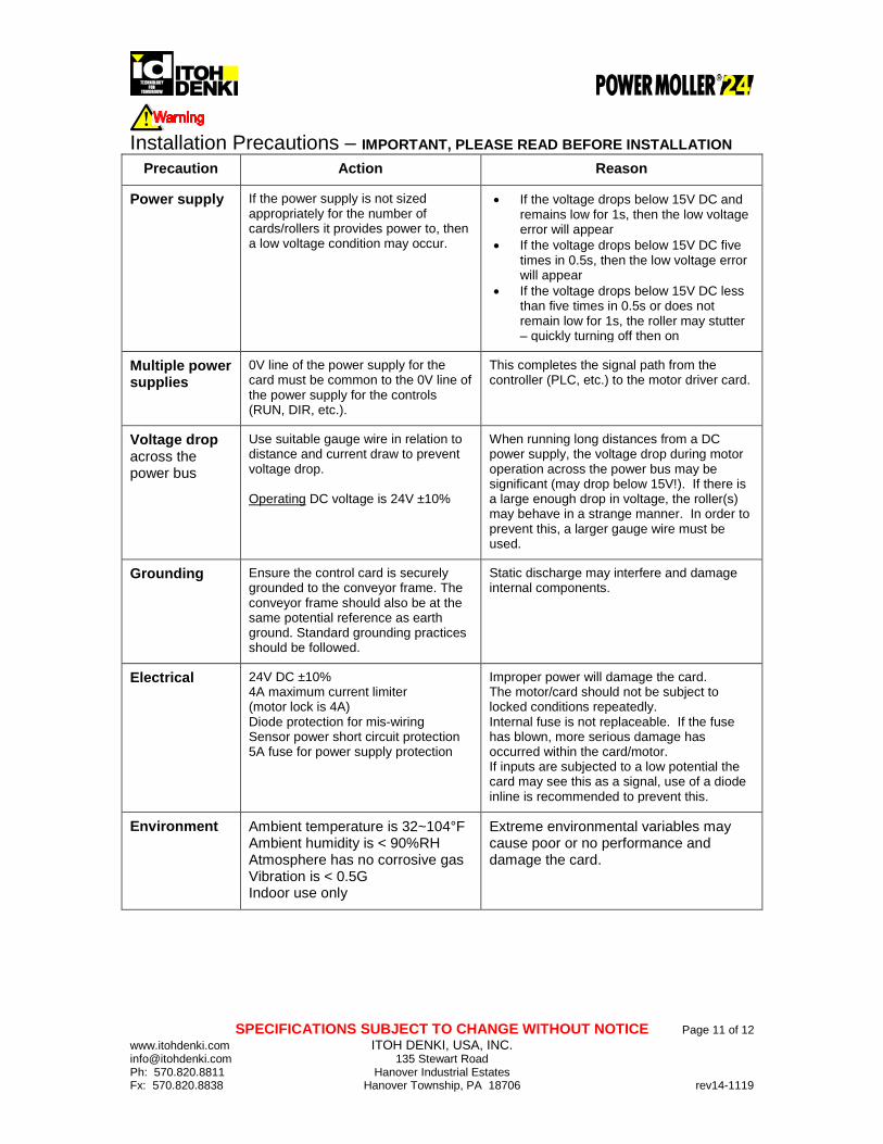
Installation Precautions – IMPORTANT, PLEASE READ BEFORE INSTALLATION
Precaution Action Reason
Power supply If the power supply is not sized appropriately for the number of cards/rollers it provides power to, then a low voltage condition may occur.
• If the voltage drops below 15V DC and remains low for 1s, then the low voltage error will appear
• If the voltage drops below 15V DC five times in 0.5s, then the low voltage error will appear
• If the voltage drops below 15V DC less than five times in 0.5s or does not remain low for 1s, the roller may stutter – quickly turning off then on
Multiple power supplies
0V line of the power supply for the card must be common to the 0V line of the power supply for the controls (RUN, DIR, etc.).
This completes the signal path from the controller (PLC, etc.) to the motor driver card.
Voltage drop across the power bus
Use suitable gauge wire in relation to distance and current draw to prevent voltage drop. Operating DC voltage is 24V ±10%
When running long distances from a DC power supply, the voltage drop during motor operation across the power bus may be significant (may drop below 15V!). If there is a large enough drop in voltage, the roller(s) may behave in a strange manner. In order to prevent this, a larger gauge wire must be used.
Grounding Ensure the control card is securely grounded to the conveyor frame. The conveyor frame should also be at the same potential reference as earth ground. Standard grounding practices should be followed.
Static discharge may interfere and damage internal components.
Electrical
24V DC ±10% 4A maximum current limiter (motor lock is 4A) Diode protection for mis-wiring Sensor power short circuit protection 5A fuse for power supply protection
Improper power will damage the card. The motor/card should not be subject to locked conditions repeatedly. Internal fuse is not replaceable. If the fuse has blown, more serious damage has occurred within the card/motor. If inputs are subjected to a low potential the card may see this as a signal, use of a diode inline is recommended to prevent this.
Environment Ambient temperature is 32~104°F Ambient humidity is < 90%RH Atmosphere has no corrosive gas Vibration is < 0.5G Indoor use only
Extreme environmental variables may cause poor or no performance and damage the card.

SPECIFICATIONS SUBJECT TO CHANGE WITHOUT NOTICE Page 12 of 12 www.itohdenki.com ITOH DENKI, USA, INC. [email protected] 135 Stewart Road Ph: 570.820.8811 Hanover Industrial Estates Fx: 570.820.8838 Hanover Township, PA 18706 rev14-1119
Revision History
Revision Number Change 12-0508 Initial document
12-0723 Added trouble shooting section
12-0810 Changed analog voltage inputs
12-1025 Spelling correction
13-0314 Added auto-sensing input diode recommendation
13-0513 Removed auto-sensing feature
14-1119 Added internal input type switch