cavitation during tensile drawing of …bib-pubdb1.desy.de/record/95383/files/polimery.pdf ·...
TRANSCRIPT

CAVITATION DURING TENSILE DRAWING OF
SEMICRYSTALLINE POLYMERS
Andrzej Pawlak, Andrzej Gałęski
Centre of Molecular and Macromolecular Studies, Polish Academy of Sciences,
Sienkiewicza 112, 90-363 Łódź
e-mail: [email protected]
Corresponding author: A. Pawlak
1
CAVITATION DURING TENSILE DRAWING OF SEMICRYSTALLINE POLYMERS
Abstract
The article presents the state of knowledge on the phenomenon of cavitation observed during
uniaxial stretching of semicrystalline polymers. Cavitation occurs when the stress at which the
amorphous phase breaks is lower than the stress initiating plastic deformation of crystals. The
text presents the process of plastic deformation, conditions in which polymers cavitate, with
special attention devoted to plastic deformation and cavitation in polyethylene, polypropylene
and polyamide.
KAWITACJE PODCZAS JEDNOOSIOWEGO ROZCIĄGANIA POLIMERÓW
CZĘŚCIOWOKRYSTALICZNYCH
Streszczenie
W artykule opisany jest stan wiedzy na temat zjawiska kawitacji, obserwowanego podczas
deformacji jednoosiowej polimerów częściowokrystalicznych. Do kawitacji dochodzi, gdy
naprężenie przy którym rozerwaniu ulega faza amorficzna ma mniejszą wartość niż
naprężenie, przy którym zaczyna się deformacja plastyczna kryształów. W tekście omówiono
szczegółowo proces deformacji plastycznej i warunki które muszą zostać spełnione aby
polimer kawitował. Szczególną uwagę zwrócono na mechanizmy deformacji plastycznej i
kawitacji w polietylenie, polipropylenie oraz poliamidzie.
Keywords: plastic deformation, cavitation, polyethylene, polypropylene
Słowa kluczowe: deformacja plastyczna, kawitacje, polietylen, polipropylen
2

Plastic deformation of semicrystalline polymers
Good mechanical properties are required in most polymer applications. The
possibilities of their control depend on the understanding of the phenomena which occur
during deformation. Regardless of many years of studies, the knowledge of deformation
mechanisms is still not complete, especially in the case of the most common kind of
deformation, i. e. uniaxial stretching. One of the issues to be examined, which is the main
subject of this paper, is cavitation during deformation, observed in some polymers under
tension.
Plastic deformation of a semicrystalline polymer is a complex process, because
different elements of amorphous and crystalline phase participate in it, depending on the level
of deformation [1-7]. Macromolecules are entangled in amorphous phase and their fragments
are elements of lamellae. As a result, polymer chains form an elastic network. In the polymers
crystallized from melt in common conditions the crystalline lamellae frequently form
spherulitic structures.
When a polymer is deformed the internal distribution of forces depends on the location
within spherulite, therefore deformation is not uniform. Usually the uniaxial tensile test [4-6,
8] provides the source of knowledge about plastic deformation of polymers, however results
of other tests, such as uniaxial compression [9,10] or plane strain compression [11-13], are
also available. The absolute values of stress and strain parameters may depend on the test
type, however the fundamental mechanisms of the polymer’s deformation process (the
exceptions discussed below) are the same. For this reason, the process of plastic deformation
may be presented on the example of uniaxial stretching.
3

When the external force is applied to a polymer, it is deformation of amorphous phase
which occurs first. This results in the changes in the position (e. g. orientation) of individual
lamellae and/or groups of lamellae and interlamellar slips, the slips being the effect of
operation of shear forces [4]. The possibilities of such deformation of amorphous phase are
limited to macroscopic strains below 10-15%. Above it, the internal stresses are high enough
to initiate chain slips inside the crystalline lamellae, so-called intralamellar slips [7]. Chain
slips are the result of a screw dislocation movement. The large number and collectivity of
these slips are responsible for the observed macroscopic yield point. The chain slips in
crystals may be fine or coarse. Usually at the beginning of plastic deformation fine slips
dominate. Later, with an increase in strain coarse slips are observed more frequently. Chain
slip is a dominating mechanism in plastic deformation of polymer crystals, but sometimes
also two other processes, twinning and phase (martensitic) transformations, are observed
[1,3,8].
If a deformed polymer is of a sperulitic structure, then after crossing the yield point
elongation of spherulites is observed. The lamellae forming spherulites are linked in a stiff
structure and at the beginning of deformation they have only limited possibility of changing
position. Moreover, the course of deformation inside the spherulite depends on the location.
This is illustrated in Fig. 1, where three significant areas are marked as A, B, C. In the polar
zone of a spherulite (A in Fig. 1) the tensile stress component is parallel to lamellar surfaces
and is responsible for crystal fragmentation at large strains. If the spaces between broken
fragments of lamellae are small, they may be filled with amorphous phase under the influence
of the compression component of stress [14].
The diagonal part of a spherulite (marked B) is the place where shear forces operate
and interlamellar slips are first initiated [15]. On the spherulite’s equator (area C) lamellae are
4

perpendicular to the direction of force and the separation of lamellae occurs at the beginning
of deformation. Sometimes the undulation of lamellae is observed in this part of a spherulite,
because the stress tensor also has a compression component [15,16].
With an increase in deformation intralamellar slips become a widespread phenomenon.
Slips result in the appearance of block structures of lamellae, individual blocks having a width
of 10-30 nm [17]. When the true strain reaches 0.6 (for PE), lamellar fragmentation begins.
Fragmentation does not necessarily mean full disintegration of crystals. At this strain also the
first fibrils are formed [18]. Fragmentation of lamellae is related to partial local stress
relaxation. Changes in the amorphous phase occurred at this phase of deformation seem to be
of smaller significance. Fragments of macromolecules may transfer from crystals into the
amorphous phase, and orientation of macromolecules or eventually breaking of bonds in
chains may occur that was detected by electron paramagnetic resonance [19].
The studies of relaxation in polyolefins conducted by Strobl’s group demonstrated that
the chains disentanglement in amorphous phase starts at the true strain of 1.0 or more [18].
The polymer deformation becomes irreversible and the polymer does not return to the initial
dimensions after stress relaxation, even if it is annealed at the temperature close to the melting
point. Disentanglement process is characteristic of tensile deformation. For plane strain
compression it has been observed that the number of entanglements does not change with
deformation [20,21]. As a result of the above described phenomena the structure is converted
from lamellar into fibrillar, when the macroscopic (engineering) strain is larger than 100%.
The process of transformation may be briefly described by Peterlin's model [22].
On the basis of studies of polyethylenes and ethylene copolymers Strobl presented a
hypothesis that there exist some characteristic strain values, related to successive deformation
mechanisms, which are the same for any polymer [18,23,24,25]. The characteristic points A
5

to D, as proposed by Strobl, are marked on the stress-strain curve, presented in Fig 2. In these
points the following mechanical processes are initiated: A- individual acts of deformation as
single lamellar separations; rotations of lamellae and interlamellar slips; B- massive chains
slips; C - lamellar fragmentation and beginning of fibrillation; and D - chains
disentanglement. It is doubtful if the same characteristic strain values were in force for
polymers so much different from polyolefins, e .g. poly(lactide acid) (PLA) or polyethylene
terephtalate in which the amorphous phase at room temperature is in a glassy state, and the
yield point (B) is reached much earlier than in HDPE. The yield in PLA is often reached at the
engineering strain below 5% [26], while for HDPE the yield strain is 10% or more.
The above description of plastic deformation does not include an important process,
which is observed in many semicrystalline polymers, i .e. cavitation during deformation. The
cavities are formed inside the strained amorphous phase. The process of cavitation is rapid
and numerous voids are formed. Cavities are of micro- and nanometer size [27-31] and are
mainly localized in the part of amorphous phase inside the spherulites [16]. Rozanski et al.
[32] showed that the increase of free volume in polymer leads to intensification of cavitation
process and it seems that initiation (nucleation) of cavitation is caused by largest free volume
fluctuations. The rapid break of polymer structure due to voiding changes the local state of
stress and influences further deformation. It seems that the influence of smaller nanocavities
on the process of deformation is more important than those of micrometer size, since their
number is significantly larger and they disturb the process of deformation on a more
fundamental level.
It should be emphasized that voids may also exist in a non-deformed polymer, as a
result of its solidification from melt. Previously we studied cavitation phenomena occuring
during isothermal crystallization [33-35]. It was demonstrated that due to differences in
6
density between the melt and the crystalline phase, negative stress is formed in the places
occluded by growing spherulites. The value of the generated pressure depends on the polymer
type and on the area of "weak" place. Our measurements showed that the negative pressure
for polyethylene is between -3 and -10 MPa [33]. Negative pressure may lead to the break of
melt before solidification or to the formation of stressed areas between spherulites. The
cavities formed during isothermal crystallization are of micrometer size.
If the process of crystallization is non-isothermal, spherulites usually grow smaller.
Also the pockets of melt occluded between growing spherulites are smaller than during
isothermal crystallization and negative pressures are lower. The solidified amorphous phase is
stressed but cavitation does not occur during non-isothermal crystallization. Probably, the
procedure of crystallization leading to a more or less strained amorphous phase may influence
further cavitation during deformation.
However, the main subject of this paper are nanometer cavities, which are formed in
the polymer in amorphous layers between crystalline lamellae during tensile deformation.
Cavitation
Cavitation has been observed in semicrystalline polymers for 20 years. For a long time
it has been treated as a marginal phenomenon. Systematic description of voids formation,
their evolution and conditions of cavitation has not been published yet. As it is known, voids
are formed during uniaxial deformation in crystallizing polymers such as: polyethylene,
polypropylene, poly(methylene oxide), poly(ethylene terephtalate), polyamide 6. The
cavitation process depends on the polymer’s morphology and deformation conditions [14,26-
29,36-45].
The cavities in polymers are usually detected by scattering techniques, most often by
7

small-angle X-ray scattering (SAXS) [27-31]. Recently, instead of the classical X-ray source
the synchrotron radiation has been applied more often [27,28,30,31,46,47]. The X-ray
radiation allows to detect the holes with a diameter of 2-80 nm. The larger cavities, of
micrometer size, scatter the light and the scattering is visible as a whitening of the material
[42]. Void formation decreases the density of a polymer, therefore cavitation may be detected
by densitometry or by complementary measurements of volume increase [48-52].
Fig. 3 presents mechanical properties of some cavitating (POM, PA 6) and non-
cavitating (LDPE) polymers and accompanying changes in volume. Cavitation in polymers is
characterized by a large volume increase, reaching 30-50% or more of the initial volume
[45,51]. This is illustrated in Fig 3b on the example of strained poly(methylene oxide) (POM)
sample. Fig. 3 also presents that for non-cavitating polymers, like LDPE, the volume is nearly
constant.
Sometimes voids are incorrectly identified as crazes. Crazes are usually generated in
amorphous polymers (PS, PC), but are also observed in semicrystalline polymers [53-56].
They are voids in which edges are joined by oriented polymer fibrils, and thanks to these
ligaments crazes are able to transfer stresses. This is not the case with cavities. The SAXS
scattering pattern from crazes has two perpendicular components - from voids and from
fibrils, and is therefore different than the pattern from voids [53]. It may be concluded that it
is the generation of cavities and not crazing which is typical of deformed crystalline polymers.
The earliest texts which dealt with cavitation were published in the seventies of the
last century. These papers mostly focused on the morphological changes during deformation,
not on cavitation. As example, Keller and Pope studied the oriented LDPE and observed an
increase in SAXS scattering with an increase in interlamellar distances [57]. Clark, in turn,
noted an increase in volume of the deformed polymer [58]. These facts were interpreted as an
8

effect of cavitation between those lamellae whose surfaces were oriented perpendicularly to
the direction of deformation [3]. The larger cracks, of a few micrometers width, were
observed by Peterlin [8] and Jang [56], inside the spherulites and on the border between
spherulites. In some cracks, located inside the spherulites, fragments of the deformed polymer
were visible, so they were wrongly interpreted as crazes [56]. The above observations
concerned late stages of the deformation process.
One of the early papers, linking deformation mechanisms to the accompanying volume
changes, was the work by Cessna [51]. He noted that when polypropylene is deformed rapidly
(20 m/min) or at very low temperatures (-190 oC), 30-40% volume increase occurs before the
break, probably as a result of voiding or crazing. Stein and co-workers analyzed X-ray
scattering from HDPE specimens tested in the deformation oscillations mode and in cold
drawing. They concluded that in the second case the anisotropic cavities were formed at the
strain of 10%. The observed voids were initially oriented perpendicularly to the direction of
deformation, but next they reoriented [59].
Galeski et al. examined the morphology of deformed polyamide, contrasted with OsO4
and sliced. They stated that traces of the previously existing cavities were visible in different
positions inside the spherulites, marked by the broken chemical bonds [15]. The analysis of
position of places which reacted with OsO4 led to the conclusion that the cavities were formed
in the equatorial parts of spherulites, between the folded (undulated) lamellae and in the polar
parts, between the broken lamellae.
In the period of 1995-1998 the group led by Butler published a cycle of three papers
on the mechanical properties of polyolefins [27,28,47]. They observed that voiding occurred
at the beginning of plastic deformation. Simultaneous SAXS and WAXS in-situ
measurements during uniaxial stretching demonstrated that cavities in HDPE appeared close
9

to the yield point, exactly at the moment of martensitic transformation of some crystals [47].
Another interesting observation was that in linear low density polyethylene (LLDPE),
characterized by thinner crystals, martensitic transformation also occurs, but without
cavitation. The second paper showed that oval scattering pattern from cavities changes
orientation at the engineering strains larger than 30% [27]. It was also observed that whitening
due to cavitation occurs around the yield point. More intensive X-ray scattering was from
cavities in polyethylene characterized by lower molecular weight [28].
Similar, simultaneous X-ray and tensile studies of polyethylene were conducted by
Hughes et al. [30], but the strain rate was higher (3s-1) in this case. It was confirmed that
cavities are formed at the yield and that whitening of samples accompanies cavitation.
Authors suggest that voids are formed in the spherulite’s equator and that the cavities are
initially elongated perpendicularly to the direction of deformation. The voids reorient with an
increase in deformation or the new ones are generated, but oriented in the direction of
deformation.
There are many works which concern cavitation in polypropylene. Liu et al. [42]
confirmed Cessna's [51] observation that whitening due to cavitation occurs when the draw
ratio is fast or the testing temperature is low. Microscopic examination by scanning electron
microscopy (SEM ) showed that whitening is in microscale accompanied by voids, located
between fibrils. Similar voids were not observed in the other samples, for which whitening
did not occur. Their second observation was that the X-ray diffraction peaks from crystalline
phase were wider in the cavitating samples, which means that fragmentation of crystals
occurred into smaller blocks.
Another group from Korea [43] noticed that if polypropylene is simultaneously kept
under hydrostatic pressure during deformation, then whitening and cavitiation are not present.
10

Yamaguchi and Nitta [44] measured light transmittance for PP samples and concluded that
whitening is visible at yield (i. e. for strain of 15%), however a decrease in transmittance
begins much earlier, at the engineering strain of 7%.
Zhang and co-workers [60] studying mechanisms of plastic deformation in the
samples previously exposed to gamma radiation from 60Co source, observed that radiated PP
cavitates shortly before yield point, if the temperature is below 60o C. They concluded that
voiding precedes a massive break of lamellar crystals and that the formation of voids is a
necessary precursor of chains slips when macromolecular chains in amorphous phase have
limited mobility or when shear inside the crystal is difficult due to low temperature or
considerable thickness of crystals.
Changes in volume in many deformed polymers were the subject of studies conducted
by G'Sell’s group [45,48,49]. An example of homopolymer characterized by a large increase
in volume is poly(ethylene terephtalate). The microscopic analysis showed that in PET two
mechanisms of deformation are present: shear bands and crazes [48]. Long crazes, with the
length of around 100 μm, were responsible for the volume increase in these polymers. In the
other of the examined polymers, poly(vinylidene fluoride), the analyzed volume was
disturbed by two processes: nucleation of cavities before yield and growth of cavities during
further deformation [61]. A large increase in volume, up to 40%, was observed by G'Sell for
polypropylene and polyethylene [45,49]. Billon [62] made a similar observation for the
injected PP specimens. Na et al. [63] discovered that the solid state annealing lead to an
increase in volume during tensile deformation, both in isotactic polypropylene and in
nucleated PP, containing mostly β phase crystals [64].
In the recent years a few papers have been published which discussed plastic
deformation and the effect of cavitation in which synchrotron radiation was applied for
11

detection of cavities. These included, among others, the articles by Schneider et al. [31] and
Jiang et al. [46]. Schneider analyzed disc-shaped HDPE samples, in which deformation was
localized by notching. As in the case of earlier works, cavities were visible starting from yield
and their shape changed with deformation. The analysis of SAXS profiles led to the
conclusion that the content of the voids’ fractions does not change during the hardening phase
of deformation, however the size of voids changes with the strain level.
It is commonly known that if a polymer has a spherulitic structure, then cavities are
formed at yield in the equatorial belt of a spherulite, where lamellar surfaces are perpendicular
to the direction of stretching and where the amorphous phase is highly stretched [15] (see Fig.
1). The fact that cavitation is in places located close to the equator was confirmed by atomic
force microscopy studies [16]. On the other hand, in the scanning electron microscopy more
visible are cavities formed as a result of breaking of lamella in the polar fans of spherulites
[15,65]. Figure 4 is the illustration of this fact for polypropylene. According to expectations
voids are not observed in the diagonal part of spherulites, under 45o to the direction of
deformation (point C in Fig. 4), where shear dominates. The number of cavities increases with
the degree of deformation. When strains are larger then the lamellar - fibrillar transformation
takes place according to Peterlin's micronecking model [66]. It appeared later that Peterlin’s
model requires voiding as a necessary condition for transformation, even if deformation
earlier occurred without cavitation. The cavities in the final phase of stretching have recently
been observed by G'Sell [67].
Our examinations of the following polymers: low density polyethylene (LDPE),
ethylene-octene copolymer (EOC), high density polyethylene (HDPE), polyamide 6 (PA),
polypropylene (PP), and poly(methylene oxide) (POM) showed that most of these polymers
cavitate during uniaxial stretching, with the exception of LDPE and EOC [40]. The same
12

polymers never cavitated during compression in the plane strain conditions. Careful analysis
of experimental results lead to the conclusion that the cavities are generated when the local
3D extensional stresses exceed the strength of amorphous phase, but are smaller than the
stresses needed for plastic deformation of crystals. For this reason cavities were visible in
polymers (POM, PP, HDPE) characterized by large, weakly defected crystals. In the case of
polymers with thin and defected crystals the plastic deformation of crystals by chain slips was
easier to initiate than the break of amorphous phase. Hence, in our experiments LDPE and
EOC did not cavitate. In the stress-strain measurements the polymers able to cavitate are
characterized by a larger yield stress (see Fig. 3a), because the yield stress increases with the
thickness of lamella and with the reduction of the number of defects in crystals.
The 3D stress is important in cavitation of semicrystalline polymers, and we may learn
that, for example, from the studies by Castagnet et al. [68] The three-dimensional tensile
stresses are not present in the compressed polymers, so amorphous phase does not break.
Comparison of the true stress-true strain curves for the uniaxially stretched and the plane
strain compressed polymers shows that there are differences between test results. The stresses
in compression at the same strain are larger than the stresses in tension. The difference is
small if the polymer does not cavitate, but large for those which cavitate [40].
One of the studied polymers, polyamide, has exhibited untypical behavior. The
character of the stress-strain dependence suggested formation of voids during the tensile test,
but both X-ray and light scattering observations did not confirm this hypothesis. Estimations
based on surface energy and thickness of amorphous layer showed that negative pressure,
preventing closing of 5.6 nm size cavities by surface tension, is for polyamide equal to -33.6
MPa. This pressure is larger than the pressure generated at yield around the void, which is
equal to -28.0 MPa. It means that the voids are formed in polyamide, but they are non stable
13

and vanish easily during deformation. This is in accordance with the previous observations by
Galeski concerning the chains break in some areas of the deformed polyamide, where cavities
were not directly visible [15]. Similar calculations for cavitating polymers (i. e. PP, POM,
HDPE) showed that in these polymers local stresses exceed the cavitation’s stability level, so
the cavities do not vanish [40].
The conclusion about existing competition between two possible processes –
cavitation and plastic deformation of crystals, was based on comparison of behavior for
different polymers deformed by stretching. However, if it is true it should be possible to
observe in one selected polymer both cavitational and non cavitational behavior, depending
on their morphology or testing condition. The aim of further experiments, done in our
laboratory and described below was to analyze the influence of different morphological
factors and experimental parameters on occurring of cavitation.
Recapitulation of recent results from our laboratory
Two subsequent sections are the synthesis and recapitulation of recent results from our
laboratory, published in years 2007-2010 [14,41,69,70,71]. In these sections we discuss the
role of morphology and experimental conditions on cavitation, respectively. The examined
materials were limited to polyolefins: high density polyethylene and polypropylene (see
Table I). Detailed descriptions of experiments may be found in [41,69,70].
a) Influence of sample morphology on cavitation process.
Two factors which influences morphology of semicrystalline polymers formed from
melt are the cooling procedure and existence or non existence of orientation (stretching or
14

shearing) forces in melt during processing. Orientation of lamellae can be an example of a
morphological factor favoring cavitation, existing for instance in the surface layer of an
injected HDPE bar [41]. The observation conducted by scanning electron microscopy (see
Fig. 5) indicated that in such a surface layer crystals are oriented perpendicularly to the
direction of deformation (and injection) on the distance up to 300 μm from the surface. When
the external force is applied, cavities in the surface layer are generated already at the strain of
0.0015 and the stress of 2 MPa. However, the cavities in the core of the same sample are
generated much later, after yield, at true stress of 29 MPa and strain of 0.3. The reason for
early cavitation in skin is strong localization of deformation in amorphous layers between
regularly displaced crystals.
The thickness of crystals and the number of defects in their structure, limiting strength
to plastic deformation, depends on the process of crystallization from melt. We examined
HDPE samples cooled from the molten state in various manner in air, in water and in iced
water. The studies showed that the cavitation did not occur in the sample that solidified most
quickly, i. e. in water with ice, in which crystals were thinnest (19.7 nm). Limited cavitation
was observed in a polymer cooled in water, where crystals had the thickness of 20.6 nm,
however very intensive cavitation was noted in HDPE cooled in air, where the thickness of
crystals was 24.3 nm. The yield stress, which is related to crystal perfection, was equal to 19,
21 and 26 MPa respectively [41].
Figure 6 presents typical SAXS patterns registered in-situ during tensile deformation
of HDPE. The elongated shape of scattering pattern indicates that cavities in polymers are
initially ellipsoidal and oriented perpendicularly to the direction of deformation. Their
dimensions are not uniform and start from a few nanometers. Usually the SAXS patterns
show the presence of 2-4 populations of voids, characterized by different values of
15

gyration radius Rg [72]. For example, the radii of gyration for a polyethylene sample with the
local strain of 0.3 were equal to 4 and 11 nm [41]. This allows to assume that the axes of
ellipsoid describing larger voids, one with Rg=11 nm, were 48 and 7 nm. The voids’ size
increase with an increase in deformation. We observed that when the local strain in HDPE
was equal to 1.4, which is related to the engineering strain of 35%, the gradual reorientation
of voids into the direction of deformation occurred, followed by further elongation at large
strains. The wide angle X-ray scattering studies (WAXS) showed that the changes in the
voids’ shape are forced by reorientation of crystals surrounding the amorphous phase [41].
X-ray scattering measurements do not provide quantitative estimations of the scale of
the cavitation phenomenon. However, if the dimensions of the sample are measured during
deformation, for example by video recording, it is possible to determine the volume changes
as a function of deformation [45,52,73]. Cavitation is responsible for nearly an entire increase
in volume and thus the increase is the measure of the voiding scale. The experiments for
HDPE specimens cooled in air showed that their volume increased significantly, even up to
100% for the local strain ɛ=7 [41]. If a polymer does not cavitate, the changes in volume are
usually small [67]. Our recent studies of isotactic polypropylene samples having different
amounts of α and β crystals showed that the volume in deformed polymer containing 90% of
β crystals may increase even 200% [71]. The intensity of SAXS scattering from voids is for β
form reach PP samples three times more than intensity of scattering from usual α form
polypropylene. However, the cavitation process, i. e. the moment of initiation, evolution of
cavities shape and void's sizes, characterized by radius of gyration, were similar in both
crystalline forms of polypropylene.
One of the factors influencing cavitation process via morphology modification is
molecular mass. We examined two polypropylenes with different molecular mass, of 4.0*105
16

g/mol and 2.5*105 g/mol, but with similar crystalline phase, i. e. characterized by the similar
degree of crystallinity and crystal thickness. The voids were more numerous in the polymer
with the lower molecular mass, where the amorphous phase was weaker and less entangled
[14].
We showed the influence of the local morphology on cavitation on the example of
deformation of thick injected polypropylene specimens. Examination by polarized light
microscopy indicated that the structure of the injected sample depends on the position in
volume, as result of different heat withdrawal during solidification. In the center large, 20-30
μm size, spherulites were formed. The closer to the surface, the number and the size of the
spherulites decreased. In the skin layer spherulites were not observed, but only small
crystalline structures. We expected that cavitation in such a gradient structure would first
occur in the center, as confirmed by the SAXS studies. The voids were not detected in the
skin layer of the specimen, even at the local strain equal to 2.6 [14].
The morphology of a polymer may be modified by annealing in the solid state, which
leads to the thickening of crystals and increase in crystallinity. We examined HDPE samples
initially crystallized in such as manner that they do not cavitate at normal testing conditions.
If the same material was annealed 3h at T=125 oC, the number of the defects in the thicker
crystals reduced, and the break of amorphous phase became easier than initiation of crystals
slips and the polymer cavitated after annealing [69].
b) Influence of experimental factors on cavitation process.
Apart from morphological factors also testing conditions such as deformation rate and
temperature influence the cavitation process, because the sensitivity of amorphous and
crystalline phase on changes of experimental conditions is different. As mentioned earlier,
17

polyolefins (PP, PE) cooled quickly from melt have small, defected crystals and do not
cavitate after yield when tested at the typical rates of 8.3*10-4 - 3.3*10-3 s-1 [14]. However, if
the deformation rate for PP sample is increased to 8.3*10-3 s-1 , then the yield stress increases
form 35 to 38 MPa and the polymer begins to cavitate. The presence of cavitation was
confirmed by a rapid increase in volume in the deformed sample, visible at the strain of 0.15
and more [14]. The opposite situation is observed for PP samples, which were previously
solidified by cooling melt in the air. These specimens cavitate when they are deformed at rate
of 8.3*10-4 s-1 and higher. We searched for the rate below which cavitation will be suppressed
and it happened at the deformation rate of 0.8*10-5 s-1. Figure 7 presents SAXS patterns for PP
samples deformed to engineering strain of 25% at different strain rates: 1.6*10-4 s-1, 0.8*10-5
s-1 and 5*10-6 s-1, respectively. Yield stress for polypropylene at such test conditions was 28, 26
and 24 MPa, respectively. Yield strain for all samples was equal 15%. The cavitation was
invisible for slower test. These results, not published previously, were confirmed by volume
strain measurement, which does not show increase of volume for slowly and very slowly
deformed samples.
Voiding in polymers also depends on the testing temperature. The studies of
commercial polypropylene Novolen 1100 N by BASF showed that a polymer which cavitates
at the temperature of 20 and 40 oC does not cavitate when the temperature is increased to 70
oC, because the barrier for initiation of plastic deformation of crystals decreases with
temperature [70]. Similar studies of HDPE deformed with the rate of 5%/min at elevated
temperatures, in range of 20-75 oC, showed that in this polymer the yield stress quickly
decreases with temperature from 27 MPa at 20 oC to 19 MPa at 40 oC and only 9 MPa at 75
oC. The whitening of this material was observed at temperatures of deformation up to 32 oC,
but not at the higher temperatures. SAXS studies of deformed samples showed that some
18
limited cavitation occur at T=40 oC, but the cavities are not detected when the temperature of
sample was 50 oC and more. The above observations of cavitation in HDPE deformed at
elevated temperatures were not published previously.
CONCLUSIONS
The cavitation is observed in many semicrystalline polymers deformed in tension, but
never in compression. The reason is that 3D negative pressure should be generated for
breaking structure of amorphous phase. The cavities are formed around yield point, at the
moment when the intensive plastic deformation of crystals begin. It is the competition
between two possible processes: generation of cavitation and initiation of plastic deformation
of crystals. If the strength of amorphous phase is lower than yield stress of crystals
deformation than the voids are formed at yield. In opposite situation, which happens when the
crystals are thin and defected, the plastic deformation of lamellae occurs without cavitation.
The formation of cavities changes rapidly local state of stress and by this promotes
further deformation and fragmentation of crystals. It means that cavitation is an important
element of deformation process. It is possible, by modifying polymer morphology or
deformation conditions, to control the scale of cavitation. It was shown for polypropylene and
polyethylene that if the crystallization process is rapid and larger numbers of defects are
generated in crystals then such polymers do not cavitate. Also increasing the test temperature
or decreasing of the straining rate leads to deformation without cavitation.
19

Acknowledgments:
The study was supported by a grant of MNiSW No. N N508 468834. We wish to express
thanks to the Hamburg Synchrotron Radiation Laboratory for the beam time granted within
the project I 20090069 EC.
Literature:
1. Galeski A.: Prog. Polym. Sci. 2003, 28, 1643.
2. Oleinik E.: Polym. Sci. Ser. C 2003, 45, 17.
3. Lin L., Argon A. S.: J. Mat. Sci. 1994, 29, 294.
4. Zhou H., Wilkes G. L., J. Mater. Sci. 1998, 33, 287.
5. Bowden P. B., Young R. J.: J. Mater. Sci. 1974, 9, 2034.
6. Peterlin A.: Coll. Polym. Sci. 1987, 265, 357.
7. Seguela R.: e-Polymers 2007, no. 032.
8. Peterlin A., in: Advances in Polymer Science and Engineering, Proceedings of the
Symposium on Polymer Sciences and Engineering, Plenum Press, New York 1972, pp
1-19.
9. Staniek E., Seguela R., Escaig B., Francois P.: J. Appl. Pol. Sci. 1999, 72, 1241.
10. Bartczak Z., Cohen R., Argon A.: Macromolecules 1992, 25, 4692.
11. Bartczak Z., Argon A., Cohen R.: Polymer 1994, 35, 3427.
12. Galeski A., Bartczak Z., Argon A.S., Cohen R.E.: Macromolecules 1992, 25, 5705.
13. Pluta M., Bartczak Z., Galeski A.: Polymer, 2000, 41, 2271.
14. Pawlak A., Galeski A.: Macromolecules 2008, 41, 2839.
15. Galeski A., Argon A. S., Cohen R. E.: Macromolecules 1988 ,21, 2761.
16. Thomas C., Ferreiro V., Coulon G., Seguela R.: Polymer 2007, 48, 6041.
17. Friedrich, K in: Advances in Polymer Sciences, vol. 52/53; Kausch H.H. Ed; Springer:
20

Berlin 1983, pp. 225-274
18. Hiss R., Hobeika S., Lynn C., Strobl G.: Macromolecules 1999, 32, 4390.
19. Campbell D., Peterlin A.: J. Polym. Sci. B 1968, 6, 481.
20. Schonherr H., Vancso G. J., Argon A. S.: Polymer 1995, 36, 2115.
21. Cassagnau P., Montfort J.P., Martin G., Monge P.: Rheolog. Acta 1993, 32, 156.
22. Peterlin A.: J. Mater Sci. 1971, 6 , 490.
23. Hobeika S., Men Y., Strobl G.: Macromolecules 2000, 33, 1827.
24. Fu Q., Men Y., Strobl G.: Polymer 2003, 44, 1941.
25. Hong K., Rastogi A., Strobl G.: Macromolecules 2004, 37, 10165.
26. Piorkowska E., Kulinski Z., Gadzinowska K.: Polimery 2009, 54, 83.
27. Butler M. F., Donald A. M., Ryan A. J.: Polymer 1997, 38, 5521.
28. Butler M. F., Donald A. M., Ryan A. J.: Polymer 1998, 39, 39.
29. Castagnet S., Girault S., Gacougnolle J. L., Dang P.: Polymer 2000, 41, 7523.
30. Hughes D. J., Mahendrasingam A., Oatway W. B., Heeley E. L., Martin C., Fuller W.:
Polymer 1997, 38, 6427.
31. Schneider K., Trabelsi S., Zafeiropoulos N. E., Davies R., Riekel Ch., Stamm M.:
Macromol. Symp. 2006, 236, 241.
32. Rozanski A., Galeski A., Debowska M.: Macromolecules 2011, 44, 20.
33. Piorkowska E., Galeski A.: J. Polym. Sci. B-Polym. Phys. 1993, 31, 1285.
34. Nowacki R., Kolasinska J., Piorkowska E.: J. Appl. Polym. Sci. 2001, 79, 2439.
35. Nowacki R., Piorkowska E.: J. Appl. Polym. Sci. 2007, 105, 1053.
36. Duffo P., Monasse B., Haudin J. M., G’Sell C., Dahoun A.: J. Mater. Sci. 1995, 30,
701.
37. Nathani H., Dasari A., Misra R. D. K.: Acta Mater. 2004, 52, 3217.
38. Li J. X., Cheung W. L.: Polymer 1999, 40, 2089.
39. Gencur S. J., Rimnac C. M., Kurtz S. M.: Biomaterials 2003, 24, 3947.
40. Pawlak A., Galeski A.: Macromolecules 2005, 38, 9688.
41. Pawlak A.: Polymer 2007, 48, 1397.
42. Liu Y., Truss R. W.: J. Polym. Sci., B. Polym. Phys. 1994, 32, 2037.
43. Pae K. D., Chiu H-C., Lee J. K., Kim J-H.: Polym. Eng. Sci. 2000, 40, 1783.
44. Yamaguchi, M., Nitta, K.-H.: Polym. Eng. Sci. 1999, 39, 833.
45. G'Sell Ch., Bai S.-L., Hiver J.-M.: Polymer 2004, 45, 5785.
21

46. Jiang Z., Tang Y., Men Y., Enderle H.-F., Lilge D., Roth S. V., Gehrke R., Rieger J.:
Macromolecules 2007, 40, 7263.
47. Butler M. F., Donald A. M., Bras W., Mant G. R., Derbyshire G. E., Ryan A.J.:
Macromolecules 1995, 28, 6383.
48. G’Sell C., Hiver J. M., Dahoun A.: Int. J. Solids and Struct. 2002, 39, 3857.
49. Addiego F., Dahoun A., G’Sell C., Hiver J. M.: Polymer 2006, 47, 4387.
50. Lazzeri A., Thio Y. S., Cohen R. E.: J. Appl. Polym. Sci. 2004, 91, 925.
51. Cessna L. C.: Polym. Eng. Sci 1974, 14, 696.
52. Naqui S. I., Robinson I.M.: J. Mat. Sci. 1993, 28, 1421.
53. Brown H. R., Kramer E. J.: J. Macromol. Sci. Phys. 1981, B19, 487.
54. Mills P.J., Kramer E. J.: J. Mater. Sci. 1985, 20, 4413.
55. Zafeiropoulos N. E., Davies R. J., Schneider K., Burghammer M., Riekel Ch., Stamm
M.: Macromol. Rapid Commun. 2006, 27, 1689.
56. Jang B. Z., Uhlmann D. R., Vander Sande B. J.: Polym. Eng. Sci. 1985, 25, 98.
57. Keller A., Pope D. P.: J. Mater. Sci. 1971, 6, 453.
58. Garber C. A., Clark E. S.: J. Macromol. Sci. Phys. 1970, B4, 499.
59. Young P., Kyu T., Suehiro S., Lin J. S., Stein R. S.: J. Polym. Sci. Polym. Phys. Ed.
1983, 21, 881.
60. Zhang X. C., Butler M. F., Cameron, R. E.: Polymer 2000, 41, 3797.
61. Quatravaux T., Elkoun S., G'Sell C., Cangemi L., Meimon Y.: J. Polym. Sci. B Polym.
Phys. 2002, 40, 2516.
62. Temimi N., Burr A., Billon N. in: Book of Abstracts. Euromech Colloquium 487.
Structure Sensitive Mechanics of Polymer Materials: Physical and Mechanical
Aspects. Strasbourg 10-13.10.2006; Remond Y., Patlazhan S. Eds; Strasbourg 2006,
pp. 67-68.
63. Na B., Lv R.: J. Appl. Polym. Sci. 2007, 105, 3274.
64. Lv R., Xu W., Na B., Yan J.: J. Appl. Polym. Sci. 2008, 108, 3185.
65. Dijkstra P. T. S., Van Dijk D. J., Huetnik J: Polym. Eng. Sci. 2002, 42, 152-160.
66. Peterlin A. Plastic deformation of crystalline polymers in: Polymeric Materials, Baer
E., Ed., American Society for Metals: Metals Park, Ohio, 1975, pp. 175-195.
67. Addiego F., Dahoun A., G'Sell C., Hiver J. M., Godard O.: Polym. Eng. Sci. 2009, 49,
1198.
22

68. Castagnet S., Deburk Y.: Mater. Sci. Eng. 2007, A 448, 56.
69. Pawlak A., Galeski A.: Polymer 2010, 51, 5771.
70. Pawlak A., Galeski A.: J. Pol. Sci. B: Pol. Phys. 2010, 48, 1271.
71. Pawlak A.: J. Appl. Polym. Sci. (in print)
72. Yamashita T., Nabeshima Y.: Polymer 2000, 41, 6067.
73. Powers J. M., Caddell R. M.: Polym. Eng. Sci. 1972, 12, 432.
23
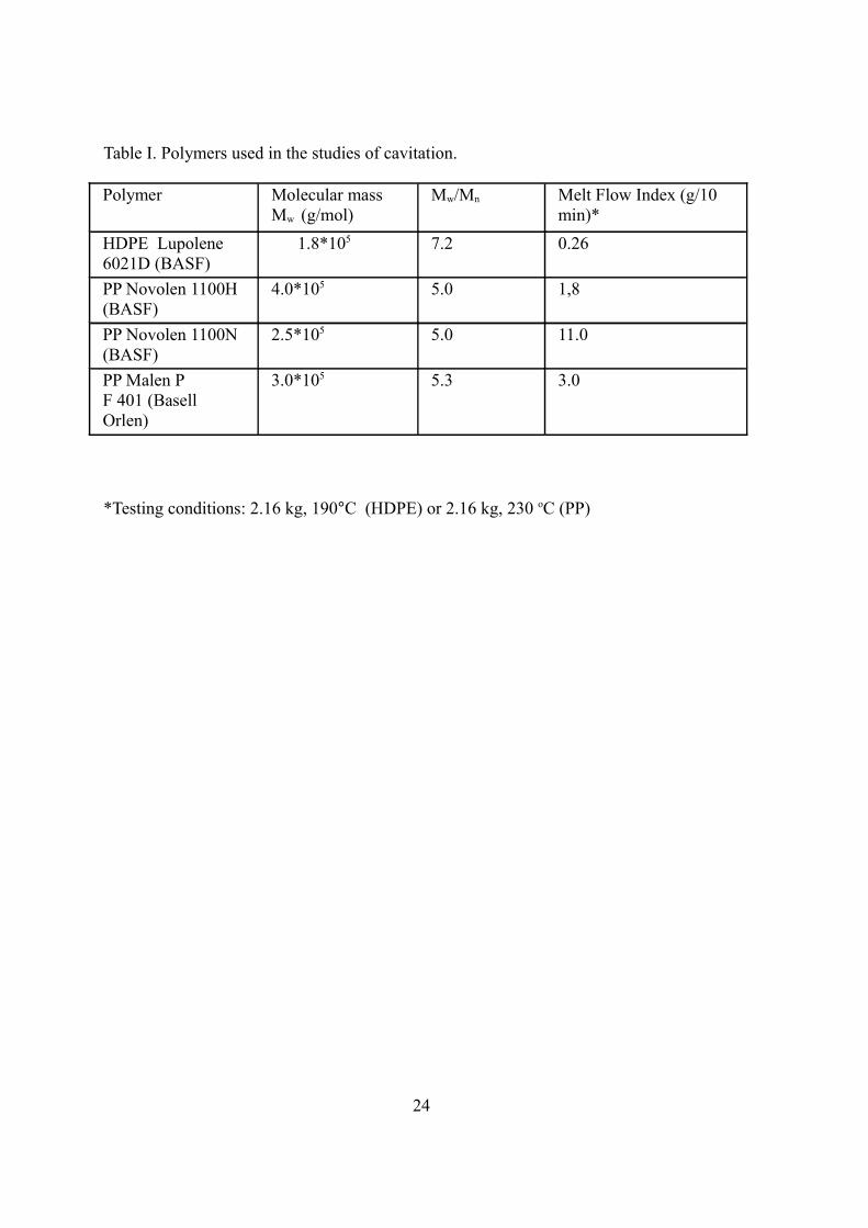
Table I. Polymers used in the studies of cavitation.
Polymer Molecular massMw (g/mol)
Mw/Mn Melt Flow Index (g/10 min)*
HDPE Lupolene 6021D (BASF)
1.8*105 7.2 0.26
PP Novolen 1100H (BASF)
4.0*105 5.0 1,8
PP Novolen 1100N (BASF)
2.5*105 5.0 11.0
PP Malen P F 401 (Basell Orlen)
3.0*105 5.3 3.0
*Testing conditions: 2.16 kg, 190°C (HDPE) or 2.16 kg, 230 oC (PP)
24

Fig. 1. Schematic of spherulite’s deformation in tension. Details of lamellar deformation in
the polar part (A), under the angle 45o (B) and in the equatorial part of the spherulite (C) are
presented.
Fig. 2.The stress-strain dependence for HDPE sample deformed at the strain rate of 5%/min.
Strobl's characteristic points of deformation [18] are marked as A-D.
25

Fig 3. Mechanical properties of selected polymers in tension (a) and related volume changes
(b).
Fig 4. Deformed spherulite of polypropylene observed by SEM. The direction of deformation
was horizontal. A - polar fan, B- equatorial area, C - diagonal, shear area, without cavities.
SD – strain direction.
26

Fig. 5. Engineering stress-strain curve for injection molded HDPE and SAXS patterns
registered for skin and core of sample (top). The morphology of skin and core is shown on
SEM photographs (right). This figure is based on the data from the studies described in [41].
27

Fig 6. The photography of deformed HDPE sample and SAXS patterns, as registered in situ
by applying synchrotron radiation. Arrows indicate the places where patterns were registered,
the numbers show local strain. Scattering on voids is clearly visible for strains of 0.6 and 3.0,
and some traces are observed for the strain of 0.15.
Fig. 7. SAXS patterns for PP samples deformed to engineering strain of 25% at different
strain rates: a) non deformed, b) 5*10-6 s-1, c) 0.8*10-5 s-1 , d) 1.6*10-4 s-1.
28

FIGURE CAPTION
Fig. 1. Schematic of spherulite’s deformation in tension. Details of lamellar deformation in
the polar part (A), under the angle 45o (B) and in the equatorial part of the spherulite (C) are
presented.
Fig 2. The stress-strain dependence for HDPE sample deformed at the strain rate of 5%/min.
Strobl's characteristic points of deformation [18] are marked as A-D.
Fig 3. Mechanical properties of selected polymers in tension (a) and related volume changes
(b).
Fig 4. Deformed spherulite of polypropylene observed by SEM. The direction of deformation
was horizontal. A - polar fan, B- equatorial area, C - diagonal, shear area, without cavities.
SD – strain direction.
Fig. 5. Engineering stress-strain curve for injection molded HDPE and SAXS patterns
registered for skin and core of sample (top). The morphology of skin and core is shown on
SEM photographs (right). This figure is based on the data from the studies described in [41].
Fig 6. The photography of deformed HDPE sample and SAXS patterns, as registered in situ
by applying synchrotron radiation. Arrows indicate the places where patterns were registered,
the numbers show local strain. Scattering on voids is clearly visible for strains of 0.6 and 3.0,
and some traces are observed for the strain of 0.15.
Fig. 7. SAXS patterns for PP samples deformed to engineering strain of 25% at different
strain rates: a) non deformed, b) 5*10-6 s-1, c) 0.8*10-5 s-1 , d) 1.6*10-4 s-1.
29