causes and performance impacts of dominant joints in slabs ......cr designs to provide load transfer...
TRANSCRIPT
PNA Construction Technologies | www.pna-inc.com | © 2018
Page 1 of 23
Causes and Performance Impacts of Dominant Joints in Slabs-on-Ground A discussion on the interaction between shrinkage and restraints for various design types
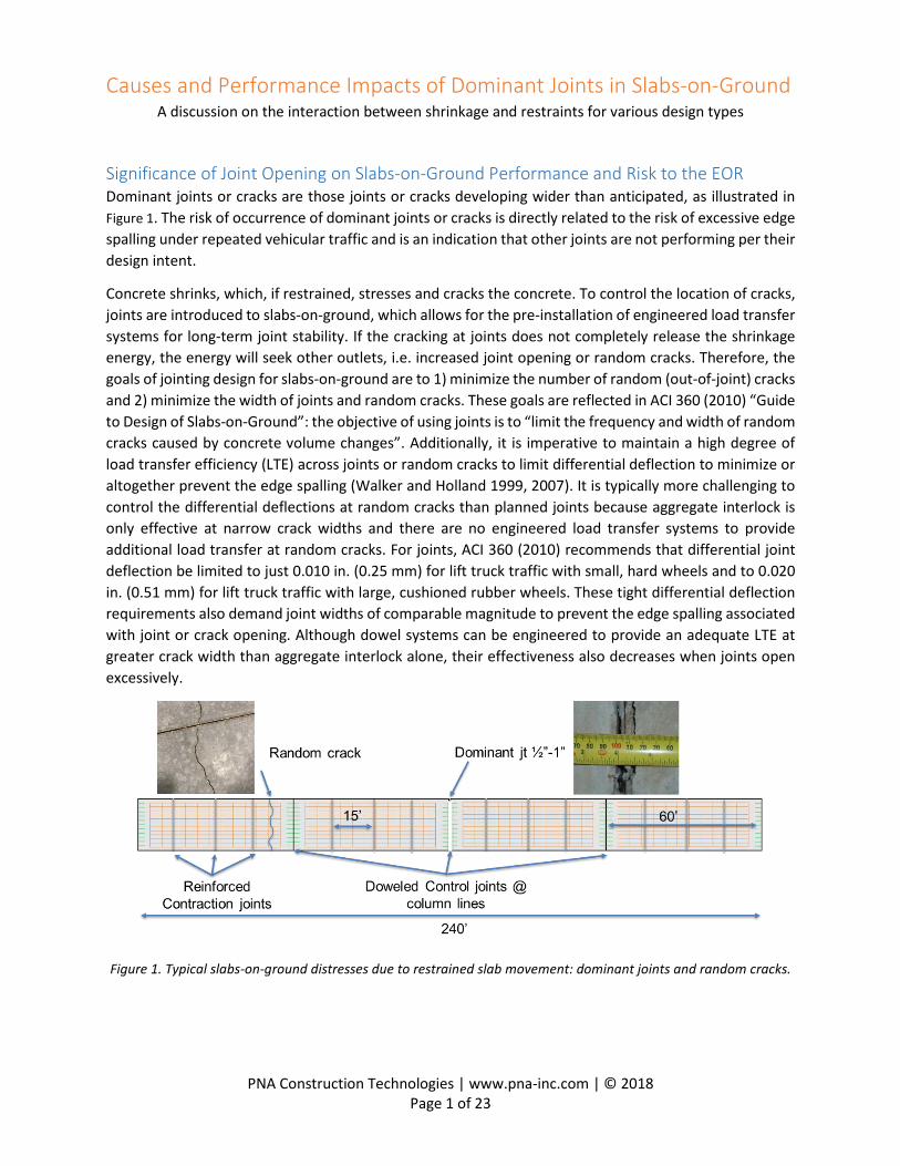
Significance of Joint Opening on Slabs-on-Ground Performance and Risk to the EOR Dominant joints or cracks are those joints or cracks developing wider than anticipated, as illustrated in Figure 1. The risk of occurrence of dominant joints or cracks is directly related to the risk of excessive edge spalling under repeated vehicular traffic and is an indication that other joints are not performing per their design intent.
Concrete shrinks, which, if restrained, stresses and cracks the concrete. To control the location of cracks, joints are introduced to slabs-on-ground, which allows for the pre-installation of engineered load transfer systems for long-term joint stability. If the cracking at joints does not completely release the shrinkage energy, the energy will seek other outlets, i.e. increased joint opening or random cracks. Therefore, the goals of jointing design for slabs-on-ground are to 1) minimize the number of random (out-of-joint) cracks and 2) minimize the width of joints and random cracks. These goals are reflected in ACI 360 (2010) “Guide to Design of Slabs-on-Ground”: the objective of using joints is to “limit the frequency and width of random cracks caused by concrete volume changes”. Additionally, it is imperative to maintain a high degree of load transfer efficiency (LTE) across joints or random cracks to limit differential deflection to minimize or altogether prevent the edge spalling (Walker and Holland 1999, 2007). It is typically more challenging to control the differential deflections at random cracks than planned joints because aggregate interlock is only effective at narrow crack widths and there are no engineered load transfer systems to provide additional load transfer at random cracks. For joints, ACI 360 (2010) recommends that differential joint deflection be limited to just 0.010 in. (0.25 mm) for lift truck traffic with small, hard wheels and to 0.020 in. (0.51 mm) for lift truck traffic with large, cushioned rubber wheels. These tight differential deflection requirements also demand joint widths of comparable magnitude to prevent the edge spalling associated with joint or crack opening. Although dowel systems can be engineered to provide an adequate LTE at greater crack width than aggregate interlock alone, their effectiveness also decreases when joints open excessively.
Figure 1. Typical slabs-on-ground distresses due to restrained slab movement: dominant joints and random cracks.
PNA Construction Technologies | www.pna-inc.com | © 2018
Page 2 of 23
Structural engineers are often tasked to provide “the” slabs-on-ground design that offers the best performance at minimum cost, without owners/developers specifying an acceptable distress level, design life, or reliability, and oftentimes without well-defined loading details – e.g., speculative buildings. However, there likely are multiple design solutions (as opposed to a singular “the” solution) for a specific project, each of which is associated with different performance and serviceability risks for the owner. Without evaluating the risk associated with each slab-on-ground design approach for each project and advising the owner on their associated risks with each approach, the engineer of record (EOR) may assume more risk than necessary, subjecting their company to callbacks and potential involvement in a lawsuit should dominant joints or random cracking that exceeds the owner’s expectation occur.
In this paper, the mechanisms of dominant joint formation are discussed; an accompanying tool that can predict the joint width and cracking potential based on these theories is available from your local PNA engineer upon request. With this tool, engineers can analyze and improve slab-on-ground designs to minimize the occurrence of dominant joints and random cracking, and be better informed on the associated risk of each design approach to be better armed for the upfront risk discussion with owners. The tool can also be used to investigate the causes of these premature distresses in previously constructed slabs-on-ground during forensic investigations as owners look to identify responsibilities.
Three Slab-on-Ground Types Depending on the location, type, and amount of steel bar reinforcement, slab-on-ground designs are commonly categorized into three types, namely strategically reinforced (SR), jointed reinforced (JR), and continuously reinforced (CR), as shown in Figure 2.
• For SR, steel is only included at the joints, in the form of an engineered dowel system to provide long-term load transfer, and there is no internal slab reinforcement. Slabs are designed to move independently from each other and are designed thick enough (with consideration of slab curl, supporting k-value, etc.) such that cracking is controlled.
• For CR, saw-cut joints are not used and the amount of steel (0.5% or greater) is sufficient to cause closely spaced, very tight cracks such that the combined aggregate and steel rebar LTE is sufficient to ensure long-term performance. Dowels are, however, typically used at construction joints in CR designs to provide load transfer because of a lack of continuity of the reinforcing steel across these joints. It is important to note that the continuous “reinforcement will not prevent cracking, but will actually increase crack frequency” (ACI 360, 2010). CR slab thicknesses are commonly assumed to be equal to that required for SR.
• For JR, a mix of locally continuous reinforcement (typically 0.1% for slabs-on-ground1) and saw-cut joints is used. The reinforcement may be interrupted at sawcut joints to allow for the intermittent use of dowels. The percent steel by area for JR is much lower than that used in cracks for CR or the dowels in joints for SR. Ultimately, the steel that spans a joint or crack in a JR falls well below that necessary to contribute to long-term load transfer on its own. Therefore, the steel must keep the crack tight or risk becoming a location of a dominant joint or crack and/or a location of spalling due to the insufficient load transfer provided by the small amount of steel. Design thick of a JR might necessarily be greater than that for SR or CR; for example, if faulting controls, the joints or cracks with only 0.1% steel cross the opening does not provide sufficient
1 If specifying between 0.1% and 0.5%, see “Stay out of the Courthouse Zone” by Wayne Walker, PE and Jerry Holland, PE at http://www.ssiteam.com/uploads/collections/Stay_out_of_the_Courthouse_Zone1.pdf

PNA Construction Technologies | www.pna-inc.com | © 2018
Page 3 of 23
load transfer to assume a reduction from edge loading condition to an interior loading condition as can be assumed with SR or CR.
Figure 2. Types of slab-on-ground designs as a function of reinforcement.
Drivers of and Restraint to Joint Opening and Random Slab Cracking A JR system with intermittent doweled sawcut contraction joints was chosen, as shown in Figure 3, for the detailed discussion in this paper. With concrete shrinkage of εsh and a temperature drop of ΔT from the concrete’s set volume and temperature, respectively, an unrestrained slab will contract (εsh + αΔT)L, where α is the coefficient of thermal expansion and contraction (CTE) of the concrete. In an ideal world with no restraint to the contraction, all joints will open uniformly and no panels will experience random cracking. However, there are many possible restraints acting against the contraction, altering or redistributing joint opening and introducing the risk of random cracking within a slab.
Figure 3. Slab deformation, joint opening, and possible restraints under environmental changes in a JR.
The first and omnipresent restraint is that between the slab and ground on which it rests, typically called subgrade/subbase friction. Because a slab shrinks toward its centroid, the substrate on which it lies exerts frictional force opposing the shrinkage (e.g., its force points outward from the centroid). The magnitude of the subgrade/subbase friction is a function of slab self-weight (e.g., density and thickness) and the friction coefficient between the slab and substrate. The friction coefficient depends both on the subgrade/subbase material and the evenness of the interface. For example, when the grading is rough or includes ruts, a higher friction coefficient can be expected as the slab keys into its supporting layer. Subgrade/subbase friction reduces joint openings compared to a zero-restraint condition. In effect, the more it reduces the joint opening, the more stress it adds in the slab to contribute to random cracking.

PNA Construction Technologies | www.pna-inc.com | © 2018
Page 4 of 23
Another source of restraint is internal reinforcement. Because steel and concrete have a similar CTE, internal reinforcement provides little restraint to contraction of concrete due to thermal changes. It does, however, restrain other forms of contraction (e.g., drying, chemical, and autogenous shrinkage). The restraint is exerted to concrete via steel/concrete shear as illustrated in Figure 3. If the reinforcement is continuous across joints, it will also contribute to the redistribution of joint openings, which will be discussed in detail in the next section. It should be noted that while rebars are tensioned at joints, this tensile force should not be included when calculating the restrained concrete deformation because it acts on internal steel only and not on the concrete slab.
Other common restraints include joint reinforcement, typically in the form of tiebars or dowels. Tiebars provide significant pullout resistance because their design is intended to ensure sufficient embedment depth such that pullout and steel yield are well balanced reactions in an effort to optimize steel content. While dowels are engineered to transfer loads across joint surface, they have smooth surfaces to create as little restraint to shrinkage as possible. However, dowels always develop some pullout resistance because concrete shrinks around them (e.g., griping each individual dowel) that is characterized as adhesion between the concrete and dowel, there is some dowel/steel friction coefficient analogous to that explained previously for the slab and its support layer, and any misalignment of the dowel may increase the pullout resistance. Ultimately, both tiebars and dowels add restraint and contribute to reduced joint opening compared to the zero-restraint condition. As with the other sources of restraint, they in-turn increase slab stresses and the risk of random cracking.
Redistribution of Jointing Opening Joint opening and stress generation for slabs-on-ground are formulated in Appendix I based on the interaction between shrinkage and the various restraints. A key assumption for deriving the mathematics is the conservation of deformation for each individual slab and its abutting joints. In other words, in Figure 3, the ends of the space of interest “L” are fixed. This is only true when there is no steel across the joint. When there is steel across a joint (e.g., rebars, tiebars, or dowels), each steel element behaves like a spring that tends to pull the adjacent slabs closer in an effort to release its internal tension. This mechanism, termed as redistribution of joint opening in this article, is illustrated in Figure 4. The steel tends to retract to its original length (or shape), which will happen if the tensile force F=kΔ is greater than the sum of friction either to its left or right. The mathematics of this mechanism can be found in Appendix II.
Figure 4. Redistribution of joint opening leading to a dominant joint.

PNA Construction Technologies | www.pna-inc.com | © 2018
Page 5 of 23
Dowel Pullout Resistance The pullout resistance of dowels can significantly impact the amount of realized joint opening. Although dowels have smooth surface, they resist pullout due to adhesion, friction, and misalignment. As shown in Figure 5, the pullout of a perfectly aligned dowel needs to first overcome the adhesive resistance, after which friction will controls for most of the displacement. Dowel-concrete adhesion can be greatly reduced by the application of debonding agent. By the same token, debonding agents also serve to lubricate and lower the dowel-concrete friction coefficient. However, because friction is the product of normal pressure and friction coefficient, there will still be significant friction if the normal pressure on a dowel is significant.
Figure 5. Dowel pullout resistance, left: laboratory test using plate dowels, right: conceptual model.
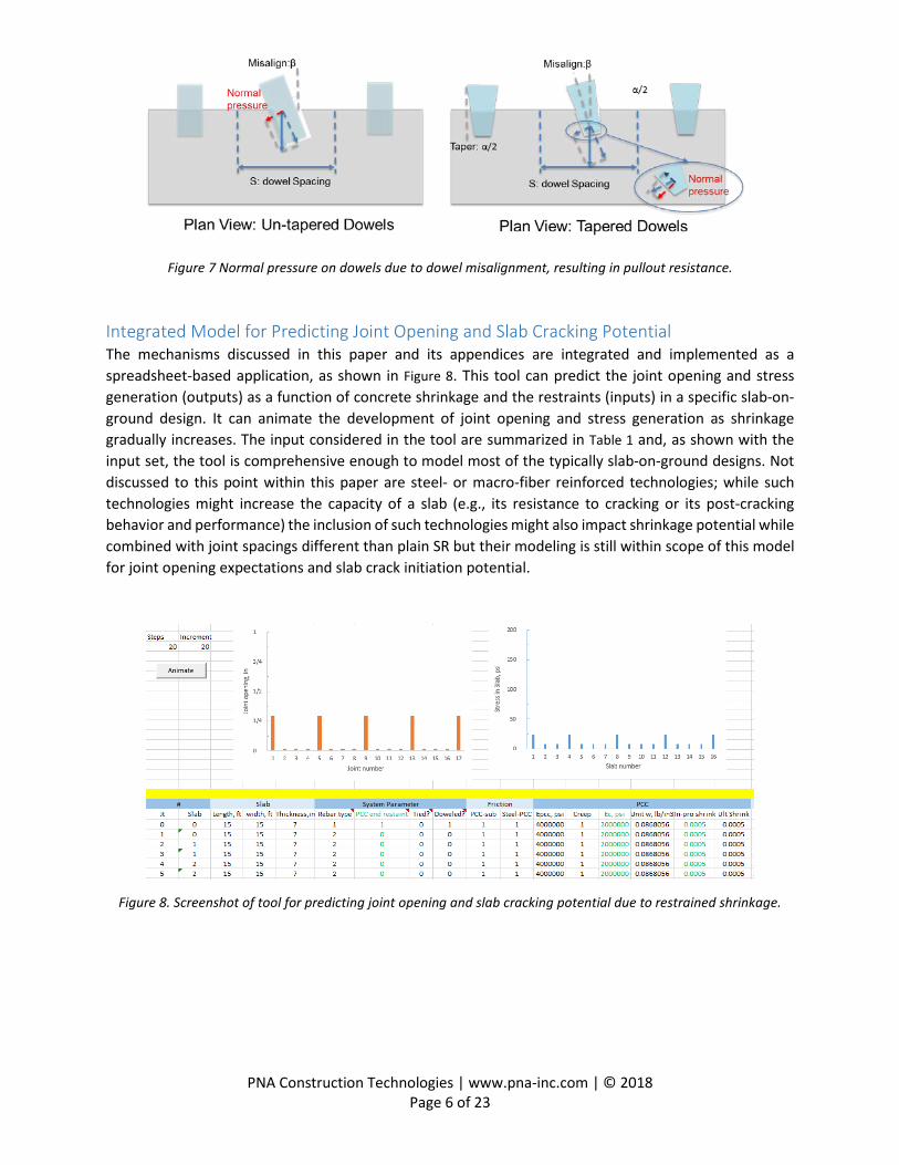
Figure 6 demonstrates that as the concrete shrinks and grips each dowel, the dowels restrain the volumetric reduction of concrete shrinkage, resulting in compression is the concrete and normal pressure on the dowels. For round dowels, this happens in all three directions, namely x, y, and z. For tapered plate dowels or dowels with compressible foam on their vertical sides, this only occurs in the z direction, which is illustrated in Appendix III. Another mechanism of dowel pullout resistance is dowel misalignment, as shown in Figure 7. This additional resistance is also frictional in nature, for which the normal pressure is a function of the degree of misalignment as well as the tapering of the sides of the dowels. In Figure 7, the normal pressure increases with misalignment, but decreases with dowel tapering. The mathematical model for determining dowel pullout resistance is presented in Appendix III.
Figure 6. Normal pressure on dowels due to concrete shrinkage, resulting in pullout resistance.
PNA Construction Technologies | www.pna-inc.com | © 2018
Page 6 of 23
Figure 7 Normal pressure on dowels due to dowel misalignment, resulting in pullout resistance.
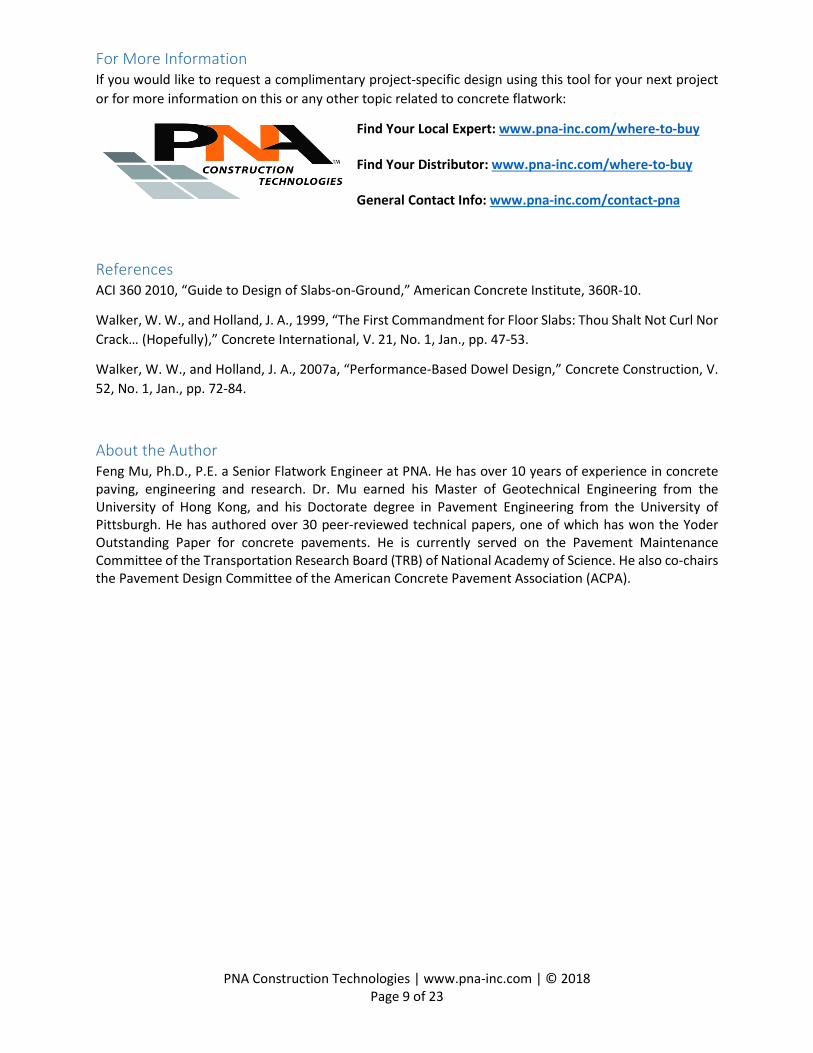
Integrated Model for Predicting Joint Opening and Slab Cracking Potential The mechanisms discussed in this paper and its appendices are integrated and implemented as a spreadsheet-based application, as shown in Figure 8. This tool can predict the joint opening and stress generation (outputs) as a function of concrete shrinkage and the restraints (inputs) in a specific slab-on-ground design. It can animate the development of joint opening and stress generation as shrinkage gradually increases. The input considered in the tool are summarized in Table 1 and, as shown with the input set, the tool is comprehensive enough to model most of the typically slab-on-ground designs. Not discussed to this point within this paper are steel- or macro-fiber reinforced technologies; while such technologies might increase the capacity of a slab (e.g., its resistance to cracking or its post-cracking behavior and performance) the inclusion of such technologies might also impact shrinkage potential while combined with joint spacings different than plain SR but their modeling is still within scope of this model for joint opening expectations and slab crack initiation potential.
Figure 8. Screenshot of tool for predicting joint opening and slab cracking potential due to restrained shrinkage.

PNA Construction Technologies | www.pna-inc.com | © 2018
Page 7 of 23
Table 1 Inputs Considered in the Integrated Tool for Joint Opening and Slab Cracking Potential
Model Properties
Benchmark Value
Model Properties
Benchmark Value
Slab Length, ft 15
Tapered Plate Dowel
Length, in. 12 Width, ft 15 Width, in. 2.5
Thickness, in. 7.0 Thickness, in. 0.5
Friction Slab-Support 1.0 Taper, ° 4.0 Steel-Concrete 1.0 Spacing, in. 18
PCC
Modulus, psi 4,000,000 Misalignment, ° 0.0 Creep 1.0
Round Dowel
Length, in. 18 Density, lb/in3 0.087 Diameter, in. 1.0
Shrinkage 500 x 10-6 Spacing, in. 12
Steel Modulus, psi 29,000,000 Misalignment, ° 0.0 Yield stress, psi 60,000 Tiebar Diameter, in. -
Rebar Diameter, in. 0.375 Spacing, in. - Spacing, in. 16
To illustrate an application of the integrated model, consider a JR slab-on-ground design, as shown in Figure 4, which has doweled construction joints at a spacing of 240 ft, sawcut contraction joints with continuous steel at 15 ft spacing, and reinforcement interrupted at doweled sawcut contraction joints every 60 ft; other inputs are taken as the benchmark values in Table 1.
The outputs of the tool are joint opening and the internal stress of the slab that indicates the potential for random slab cracking, an example of which is shown in Figure 9 and Figure 10. The numbering of the joints and slabs is as shown in Figure 4. In Figure 9, an average of ¼ in. joint opening can be anticipated at the column-line contraction joints for the benchmark JR case with tapered plate dowels in all doweled joints; the wider joint openings at the column line joints are caused by the redistribution of joint opening. If round dowels are used in lieu of tapered plate dowels, the dynamic of the system changes resulting in a construction joint opening up to 1-1/8 in., as shown in Figure 10. This is because the round dowels provide much higher pullout resistance, causing joint openings to redistribute because of this added system restraint from the round dowels.
Figure 9. Results of benchmark JR case with tapered plate dowels at column-line joints.

PNA Construction Technologies | www.pna-inc.com | © 2018
Page 8 of 23
Figure 10. Results of benchmark JR case with round dowels at column-line joints.
Factors Affecting Jointing Opening and Cracking Potential for SR, JR, and CR Designs The integrated model enables more detailed investigation of common slab-on-ground systems than ever before, with consideration of the interaction between shrinkage and restraints. The sensitivity and stability of typical SR, JR, and CR designs were further studied, with highlights presented in Appendix IV (SR), Appendix V (JR), and Appendix (CR). First, it should be noted that sensitivity and stability are two different measures of a system. Sensitivity is defined as a system’s response to the change of one property across the whole system – e.g., changing the length for all the slabs. Stability is defined as a system’s response to the change of one property for only a part of the system – e.g., changing the length for only one or a few slabs. Sensitivity and stability, when combined, reveal the reliability of a system as its as-built condition deviates from the ideal design condition, which is inevitable in the field. The study of sensitivity and stability of these designs can also shed light on the possible causes for some of the premature failures observed in the field. Thus, through consideration of sensitivity and stability during the design phase, much can be learned by the EOR and communicated to the owner about construction-related-risk of the common slab-on-ground design types.
Conclusions Dominant joints result from concrete shrinkage and redistribution of joint opening. Restraints to shrinkage can affect joint opening and induce random slab cracking, as has been fairly understood, in-turn redistributing the joint openings to form dominant joints. In this paper, the mechanisms contributing to joint opening and stress generation in the slabs were presented. A spreadsheet-based tool that systematically incorporates the mechanisms was developed and applied to comprehensively evaluate the sensitivity and stability of various slabs-on-ground designs.
It is envisioned that this tool can help designers improve slab-on-ground designs to minimize premature failures such as dominant joints and random cracking. The designers can also use it evaluate the risks associated with their design or design alternatives, based on which the risk can be more transparently shared among the owners, engineers, and contractors.
PNA Construction Technologies | www.pna-inc.com | © 2018
Page 9 of 23
For More Information If you would like to request a complimentary project-specific design using this tool for your next project or for more information on this or any other topic related to concrete flatwork:
Find Your Local Expert: www.pna-inc.com/where-to-buy Find Your Distributor: www.pna-inc.com/where-to-buy General Contact Info: www.pna-inc.com/contact-pna
References ACI 360 2010, “Guide to Design of Slabs-on-Ground,” American Concrete Institute, 360R-10.
Walker, W. W., and Holland, J. A., 1999, “The First Commandment for Floor Slabs: Thou Shalt Not Curl Nor Crack… (Hopefully),” Concrete International, V. 21, No. 1, Jan., pp. 47-53.
Walker, W. W., and Holland, J. A., 2007a, “Performance-Based Dowel Design,” Concrete Construction, V. 52, No. 1, Jan., pp. 72-84.
About the Author Feng Mu, Ph.D., P.E. a Senior Flatwork Engineer at PNA. He has over 10 years of experience in concrete paving, engineering and research. Dr. Mu earned his Master of Geotechnical Engineering from the University of Hong Kong, and his Doctorate degree in Pavement Engineering from the University of Pittsburgh. He has authored over 30 peer-reviewed technical papers, one of which has won the Yoder Outstanding Paper for concrete pavements. He is currently served on the Pavement Maintenance Committee of the Transportation Research Board (TRB) of National Academy of Science. He also co-chairs the Pavement Design Committee of the American Concrete Pavement Association (ACPA).

PNA Construction Technologies | www.pna-inc.com | © 2018
Page 10 of 23
Appendix I. Joint Opening and Internal Stress Generation prior to Redistribution Assuming only concrete drying shrinkage, the conservation of deformation for a half concrete slab, as shown in Figure 3, is:
𝜀𝜀𝑠𝑠ℎ𝐿𝐿2
= ∆𝑋𝑋𝑠𝑠,𝑖𝑖 + ∆𝑋𝑋𝑐𝑐 + ∆𝑋𝑋0 where:
𝜀𝜀𝑠𝑠ℎ: shrinkage of concrete 𝐿𝐿: slab length, in. ∆𝑋𝑋𝑐𝑐: restrained deformation of a half concrete slab, in. ∆𝑋𝑋𝑠𝑠,𝑖𝑖: deformation of internal steel reinforcement, in. ∆𝑋𝑋0: slippage of rebar at joint, in.
The restrained deformation of a half slab can be calculated as:
∆𝑋𝑋𝑐𝑐 = �𝐹𝐹𝑓𝑓(𝑥𝑥) + 𝐹𝐹𝑠𝑠(𝑥𝑥) + 𝐹𝐹𝑝𝑝
ℎ𝐸𝐸𝑐𝑐𝑑𝑑𝑥𝑥
𝐿𝐿/2
0
where: 𝑥𝑥: distance from centroid of slab, in. ℎ: slab thickness, in. 𝐸𝐸𝑐𝑐: Young’s modulus of concrete after discounting for creep, psi 𝐸𝐸𝑐𝑐 = 𝐸𝐸𝑐𝑐0/(1 + 𝐶𝐶) 𝐸𝐸𝑐𝑐0: Young’s modulus of concrete, psi 𝐶𝐶: Creep coefficient 𝐹𝐹𝑓𝑓: subgrade/subbase frictional resistance per unit width of slab, lbf/in., 𝐹𝐹𝑓𝑓(𝑥𝑥) = 𝛾𝛾ℎ �𝐿𝐿
2− 𝑥𝑥� 𝜇𝜇𝑐𝑐−𝑠𝑠𝑠𝑠𝑠𝑠
𝐹𝐹𝑠𝑠: rebar shear resistance per unit width of slab, lbf/in., 𝐹𝐹𝑠𝑠(𝑥𝑥) = 𝑛𝑛𝑛𝑛𝑛𝑛𝑑𝑑𝑠𝑠 �𝐿𝐿2− 𝑥𝑥�
𝐹𝐹𝑝𝑝: tiebar and dowel pullout resistance per unit width of slab, lbf/in. 𝛾𝛾: unit weight of concrete, pci 𝜇𝜇𝑐𝑐−𝑠𝑠𝑠𝑠𝑠𝑠: friction coefficient between concrete slab and subgrade/subbase 𝑛𝑛: rebar density 𝑛𝑛 = 1/𝑂𝑂𝑠𝑠, 1/in. 𝑂𝑂𝑠𝑠: rebar spacing, in. 𝑛𝑛: shear stress between concrete and rebar, psi 𝑑𝑑𝑠𝑠: rebar diameter, in.
The deformation of internal reinforcement can be expressed as:
∆𝑋𝑋𝑠𝑠,𝑖𝑖 = �𝐹𝐹𝑠𝑠(𝑥𝑥) − 𝐹𝐹𝑟𝑟
𝑛𝑛𝑛𝑛 𝑑𝑑𝑠𝑠2
4 𝐸𝐸𝑠𝑠𝑑𝑑𝑥𝑥
𝐿𝐿/2
0
where: 𝐹𝐹𝑟𝑟: joint rebar tensile force per unit width of slab, lbf/in. 𝐸𝐸𝑠𝑠: Young’s modulus of steel, psi
Therefore, the joint opening can be determined as:
∆𝐽𝐽= 2 �𝜀𝜀𝑠𝑠ℎ𝐿𝐿
2− ∆𝑋𝑋𝑐𝑐�
The maximum stress in the concrete can be determined as:
𝜎𝜎𝑚𝑚𝑚𝑚𝑚𝑚,𝑐𝑐 = 𝛾𝛾𝐿𝐿2𝜇𝜇𝑐𝑐−𝑠𝑠𝑠𝑠𝑠𝑠 +
𝑛𝑛𝑛𝑛𝑛𝑛𝑑𝑑𝑠𝑠ℎ
𝐿𝐿2
+𝐹𝐹𝑝𝑝ℎ

PNA Construction Technologies | www.pna-inc.com | © 2018
Page 11 of 23
Appendix II. Joint Opening Redistribution The friction of the slabs to the left and right of a joint are defined as 𝐹𝐹𝑙𝑙 and 𝐹𝐹𝑅𝑅 , which can be determined as:
𝐹𝐹𝑙𝑙𝑖𝑖 = �𝐹𝐹𝑙𝑙𝑖𝑖−1 + 𝑟𝑟ℎ
𝐿𝐿2𝜇𝜇𝑐𝑐−𝑠𝑠𝑠𝑠𝑠𝑠, 𝐹𝐹𝑗𝑗𝑗𝑗𝑖𝑖𝑛𝑛𝑗𝑗𝑖𝑖 > 𝐹𝐹𝑙𝑙𝑖𝑖−1 + 𝑟𝑟ℎ
𝐿𝐿2𝜇𝜇𝑐𝑐−𝑠𝑠𝑠𝑠𝑠𝑠
𝐹𝐹𝑗𝑗𝑗𝑗𝑖𝑖𝑛𝑛𝑗𝑗𝑖𝑖, 𝑗𝑗𝑗𝑗ℎ𝑒𝑒𝑟𝑟𝑒𝑒𝑖𝑖𝑠𝑠𝑒𝑒
where:
𝐹𝐹𝑗𝑗𝑗𝑗𝑖𝑖𝑗𝑗𝑗𝑗𝑖𝑖 = (𝑛𝑛𝑓𝑓𝑠𝑠𝐴𝐴𝑠𝑠)𝑅𝑅𝑅𝑅𝑠𝑠𝑚𝑚𝑟𝑟+(𝑛𝑛𝑓𝑓𝑠𝑠𝐴𝐴𝑠𝑠)𝑗𝑗𝑖𝑖𝑅𝑅 + 𝑛𝑛𝑑𝑑𝐹𝐹𝑝𝑝𝑠𝑠𝑙𝑙𝑙𝑙𝑗𝑗𝑠𝑠𝑗𝑗, the pullout of rebar, tiebar and dowel at joint i, and 𝐹𝐹𝑅𝑅𝑖𝑖 can be determined similarly
There are three possibilities for the redistribution of joint opening ∆𝑗𝑗. In the following equations, 𝑑𝑑𝑙𝑙𝑅𝑅𝑓𝑓𝑗𝑗 and 𝑑𝑑𝑟𝑟𝑖𝑖𝑟𝑟ℎ𝑗𝑗 are the proportions of the redistribution of joint to the left and right:
1. when both 𝐹𝐹𝑙𝑙 > 𝐹𝐹𝑗𝑗𝑗𝑗𝑖𝑖𝑗𝑗𝑗𝑗 and 𝐹𝐹𝑅𝑅 > 𝐹𝐹𝑗𝑗𝑗𝑗𝑖𝑖𝑗𝑗𝑗𝑗, the steel will yield and there is no distribution. ∆𝑗𝑗′= ∆𝑗𝑗
2. when both 𝐹𝐹𝑙𝑙 < 𝐹𝐹𝑗𝑗𝑗𝑗𝑖𝑖𝑗𝑗𝑗𝑗 and 𝐹𝐹𝑙𝑙 < 𝐹𝐹𝑅𝑅 a) If 𝐹𝐹𝑙𝑙 < 𝑛𝑛𝑑𝑑𝐹𝐹𝑝𝑝𝑠𝑠𝑙𝑙𝑙𝑙𝑗𝑗𝑠𝑠𝑗𝑗
∆𝑗𝑗′= ∆𝑋𝑋0 𝑑𝑑𝑙𝑙𝑅𝑅𝑓𝑓𝑗𝑗 = 1(∆𝑗𝑗 − ∆𝑗𝑗′ ) 𝑑𝑑𝑟𝑟𝑖𝑖𝑟𝑟ℎ𝑗𝑗 = 0(∆𝑗𝑗 − ∆𝑗𝑗′ )
b) if 𝐹𝐹𝑙𝑙 ≥ 𝑛𝑛𝑑𝑑𝐹𝐹𝑝𝑝𝑠𝑠𝑙𝑙𝑙𝑙𝑗𝑗𝑠𝑠𝑗𝑗
∆𝑗𝑗′= (1 +𝐹𝐹𝑙𝑙 − 𝑛𝑛𝑑𝑑𝐹𝐹𝑝𝑝𝑠𝑠𝑙𝑙𝑙𝑙𝑗𝑗𝑠𝑠𝑗𝑗
𝐸𝐸𝑠𝑠(𝑛𝑛𝑗𝑗𝐴𝐴𝑠𝑠,𝑗𝑗 + 𝑛𝑛𝑟𝑟𝐴𝐴𝑠𝑠,𝑟𝑟))∆𝑋𝑋0
𝑑𝑑𝑙𝑙𝑅𝑅𝑓𝑓𝑗𝑗 = 1(∆𝑗𝑗 − ∆𝑗𝑗′ ) 𝑑𝑑𝑟𝑟𝑖𝑖𝑟𝑟ℎ𝑗𝑗 = 0(∆𝑗𝑗 − ∆𝑗𝑗′ )
3. when both 𝐹𝐹𝑅𝑅 < 𝐹𝐹𝑗𝑗𝑗𝑗𝑖𝑖𝑗𝑗𝑗𝑗 and 𝐹𝐹𝑅𝑅 < 𝐹𝐹𝑙𝑙
a) If 𝐹𝐹𝑅𝑅 < 𝑛𝑛𝑑𝑑𝐹𝐹𝑝𝑝𝑠𝑠𝑙𝑙𝑙𝑙𝑗𝑗𝑠𝑠𝑗𝑗 ∆𝑗𝑗′= ∆𝑋𝑋0
𝑑𝑑𝑙𝑙𝑅𝑅𝑓𝑓𝑗𝑗 = 0(∆𝑗𝑗 − ∆𝑗𝑗′ ) 𝑑𝑑𝑟𝑟𝑖𝑖𝑟𝑟ℎ𝑗𝑗 = 1(∆𝑗𝑗 − ∆𝑗𝑗′ )
b) if 𝐹𝐹𝑅𝑅 ≥ 𝑛𝑛𝑑𝑑𝐹𝐹𝑝𝑝𝑠𝑠𝑙𝑙𝑙𝑙𝑗𝑗𝑠𝑠𝑗𝑗
∆𝑗𝑗′= (1 +𝐹𝐹𝑅𝑅 − 𝑛𝑛𝑑𝑑𝐹𝐹𝑝𝑝𝑠𝑠𝑙𝑙𝑙𝑙𝑗𝑗𝑠𝑠𝑗𝑗
𝐸𝐸𝑠𝑠(𝑛𝑛𝑗𝑗𝐴𝐴𝑠𝑠,𝑗𝑗 + 𝑛𝑛𝑟𝑟𝐴𝐴𝑠𝑠,𝑟𝑟))∆𝑋𝑋0
𝑑𝑑𝑙𝑙𝑅𝑅𝑓𝑓𝑗𝑗 = 0(∆𝑗𝑗 − ∆𝑗𝑗′ ) 𝑑𝑑𝑟𝑟𝑖𝑖𝑟𝑟ℎ𝑗𝑗 = 1(∆𝑗𝑗 − ∆𝑗𝑗′ )

PNA Construction Technologies | www.pna-inc.com | © 2018
Page 12 of 23
Appendix III. Dowel Pullout Resistance
Figure AIII-1. Normal pressure on dowels due to concrete shrinkage, top: dowels without compressible foam on the sides; bottom: tapered plate dowels or dowels with compressible foam on the sides.
As shown in Figure AIII-1, the dowel pullout resistance due to concrete shrinkage is calculated as:
𝑃𝑃𝑠𝑠ℎ𝑟𝑟𝑖𝑖𝑗𝑗𝑟𝑟𝑚𝑚𝑟𝑟𝑅𝑅 = 𝜀𝜀𝑑𝑑𝐸𝐸𝑐𝑐𝐴𝐴𝑑𝑑𝜇𝜇𝑐𝑐−𝑠𝑠
where the concrete strain due to concrete shrinkage is 𝜀𝜀𝑑𝑑 = 𝜀𝜀𝑥𝑥+𝜀𝜀𝑦𝑦+𝜀𝜀𝑧𝑧3
and 𝐴𝐴𝑑𝑑 is the surface area of the dowel.
Figure AIII-2. Normal pressure on dowels due to misalignment.
As shown in Figure AIII-2, the pullout resistance due to misalignment can be determined as follows
For round dowels and un-tapered plate/square dowels:
𝑃𝑃𝑚𝑚𝑖𝑖𝑠𝑠𝑚𝑚𝑙𝑙𝑖𝑖𝑟𝑟𝑗𝑗 = 𝜀𝜀𝑠𝑠ℎ𝐸𝐸𝑐𝑐𝑆𝑆𝐻𝐻𝑝𝑝𝑐𝑐𝑐𝑐tan (𝛽𝛽)𝜇𝜇𝑐𝑐−𝑠𝑠
For tapered plate dowels:
𝑃𝑃𝑚𝑚𝑖𝑖𝑠𝑠𝑚𝑚𝑙𝑙𝑖𝑖𝑟𝑟𝑗𝑗 = 𝜀𝜀𝑠𝑠ℎ𝐸𝐸𝑐𝑐𝑆𝑆𝐻𝐻𝑝𝑝𝑐𝑐𝑐𝑐tan (𝛽𝛽)cos (𝛼𝛼/2)𝜇𝜇𝑐𝑐−𝑠𝑠

PNA Construction Technologies | www.pna-inc.com | © 2018
Page 13 of 23
Appendix IV. Sensitivity and Stability of Strategic Reinforced (SR) Slab-on-Ground Design The benchmark SR design has similar inputs as the benchmark case in Table 1, except that there is no internal reinforcement and round dowels are used at all the joints.
Sensitivity
Figure AIV-1. Sensitivity of SR design to concrete slab and subgrade/subbase friction.
Figure AIV-2. Sensitivity of SR design to concrete-steel friction.
Figure AIV-3. Sensitivity of SR design to round dowel misalignment.

PNA Construction Technologies | www.pna-inc.com | © 2018
Page 14 of 23
Stability
Figure AIV-4. Stability of SR design to slab thickness.
Figure AIV-5. Stability of SR design to concrete-steel (dowel) friction.
Figure AIV-6. Stability of SR design to concrete modulus.
Figure AIV-7. Stability of SR design to concrete shrinkage.

PNA Construction Technologies | www.pna-inc.com | © 2018
Page 15 of 23
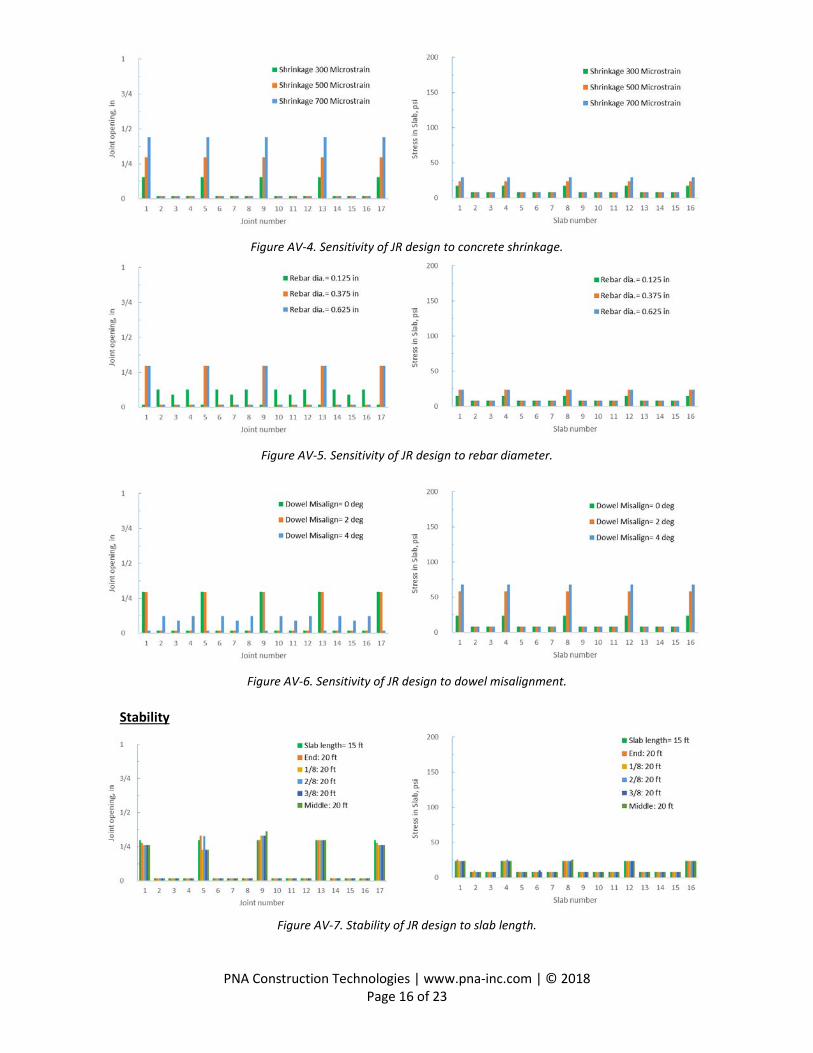
Appendix IV. Sensitivity and Stability of Jointed Reinforced (JR) Slab-on-Ground Design The benchmark JR design is the same as the benchmark case described in Table 1 and the paper text.
Sensitivity
Figure AV-1. Sensitivity of JR design to slab length.
Figure AV-2. Sensitivity of JR design to concrete slab and subgrade/subbase friction.
Figure AV-3. Sensitivity of JR design to concrete-steel friction.
PNA Construction Technologies | www.pna-inc.com | © 2018
Page 16 of 23
Figure AV-4. Sensitivity of JR design to concrete shrinkage.
Figure AV-5. Sensitivity of JR design to rebar diameter.
Figure AV-6. Sensitivity of JR design to dowel misalignment.
Stability
Figure AV-7. Stability of JR design to slab length.

PNA Construction Technologies | www.pna-inc.com | © 2018
Page 17 of 23
Figure AV-8. Stability of JR design to slab thickness.
Figure AV-9. Stability of JR design to concrete slab and subgrade/subbase friction.
Figure AV-10. Stability of JR design to concrete-steel friction (note change of joint opening scale).

PNA Construction Technologies | www.pna-inc.com | © 2018
Page 18 of 23
Figure AV-11. Stability of JR design to concrete modulus.
Figure AV-12. Stability of JR design to concrete shrinkage.
Figure AV-13. Stability of JR design to dowel misalignment.

PNA Construction Technologies | www.pna-inc.com | © 2018
Page 19 of 23
Appendix VI. Sensitivity and Stability of Continuously Reinforced (CR) Slab-on-Ground Design The benchmark CR design is like that in Table 1, except that the steel reinforcement is continuous and without any dowels between construction joints (e.g., full reinforced and undoweled sawcut contraction joints). At construction joints, tiebars and dowels are used in an alternate pattern.
Sensitivity
Figure AVI-1. Sensitivity of CR design to slab length.
Figure AVI-2. Sensitivity of CR design to concrete slab and subgrade/subbase friction.
Figure AVI-3. Sensitivity of CR design to concrete-steel friction.

PNA Construction Technologies | www.pna-inc.com | © 2018
Page 20 of 23
Figure AVI-4. Sensitivity of CR design to concrete modulus.
Figure AVI-5. Sensitivity of CR design to concrete shrinkage.
Figure AVI-6. Sensitivity of CR design to rebar size (note change of joint opening scale).
Figure AVI-7. Sensitivity of CR design to rebar spacing.

PNA Construction Technologies | www.pna-inc.com | © 2018
Page 21 of 23
Figure AVI-8. Sensitivity of CR design to tiebar size.
Figure AVI-9. Sensitivity of CR design to tiebar spacing.
Stability
Figure AVI-10. Stability of CR design to slab length.
Figure AVI-11. Stability of CR design to slab thickness.

PNA Construction Technologies | www.pna-inc.com | © 2018
Page 22 of 23
Figure AVI-12. Stability of CR design to concrete slab and subgrade-subbase friction.
Figure AVI-13. Stability of CR design to concrete shrinkage.
Figure AVI-14. Stability of CR design to steel yield strength.
Figure AVI-15. Stability of CR design to rebar size.
PNA Construction Technologies | www.pna-inc.com | © 2018
Page 23 of 23
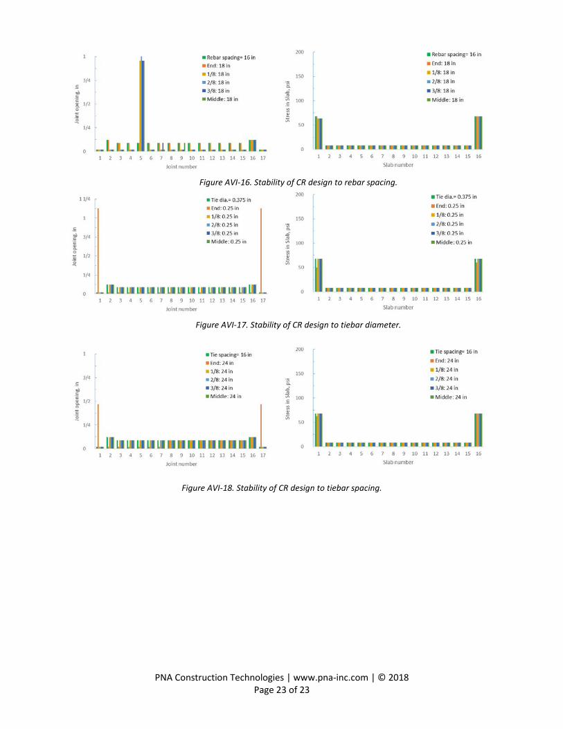
Figure AVI-16. Stability of CR design to rebar spacing.
Figure AVI-17. Stability of CR design to tiebar diameter.
Figure AVI-18. Stability of CR design to tiebar spacing.