catalytic nanoparticle growth and nanotube morphology in a
TRANSCRIPT

1
Catalytic Nanoparticle Growth and Nanotube
Morphology in a Continuous Gas Phase
Process for Carbon Nanotube Synthesis
C. Hoecker1, F. Smail2, M. Pick2 and A.M. Boies1
1Department of Engineering, University of Cambridge2Q-Flo Limited, BioCity, Nottingham
Cambridge Particle Meeting
28th June 2014
Introduction – The CNT-Fiber-Spinning-Process
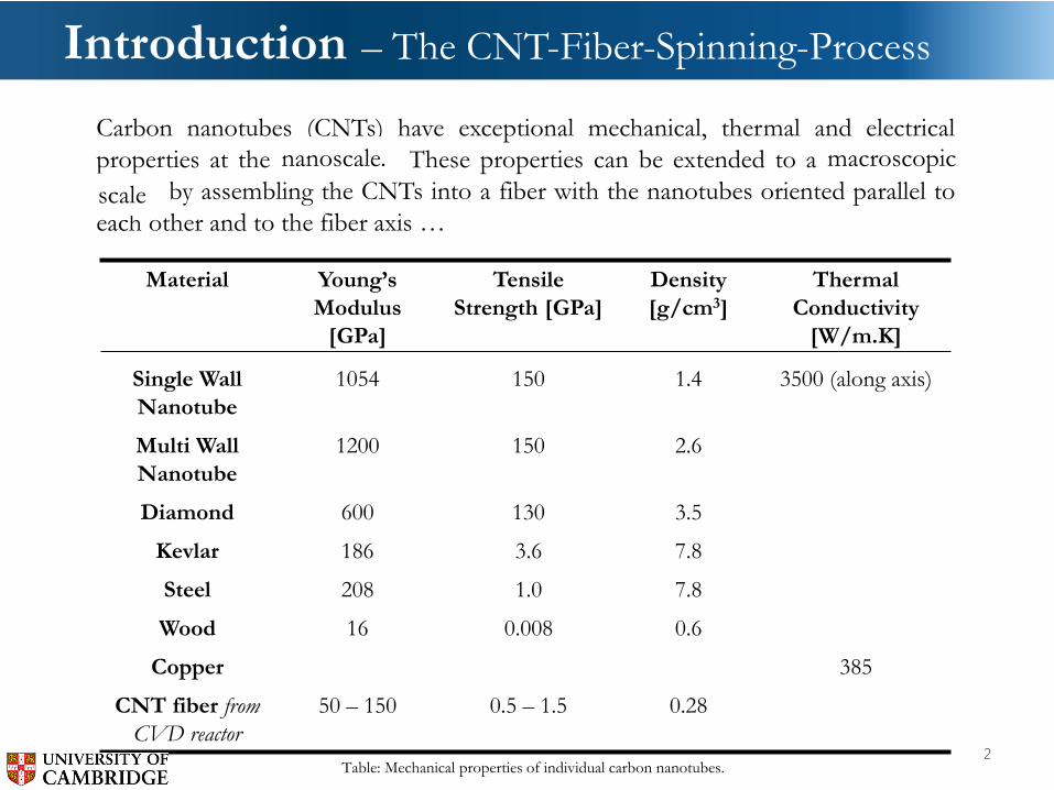
Carbon nanotubes (CNTs) have exceptional mechanical, thermal and electrical
properties at the nanoscale These properties can be extended to a macroscopic
scale by assembling the CNTs into a fiber with the nanotubes oriented parallel to
each other and to the fiber axis …
Material Young’s
Modulus
[GPa]
Tensile
Strength [GPa]
Density
[g/cm3]
Thermal
Conductivity
[W/m.K]
Single Wall
Nanotube
1054 150 1.4 3500 (along axis)
Multi Wall
Nanotube
1200 150 2.6
Diamond 600 130 3.5
Kevlar 186 3.6 7.8
Steel 208 1.0 7.8
Wood 16 0.008 0.6
Copper 385
CNT fiber from
CVD reactor
50 – 150 0.5 – 1.5 0.28
Table: Mechanical properties of individual carbon nanotubes.
nanoscale. macroscopic
2
scale

Introduction - CNT Fibre Strength Properties
Knot Test
Courtesy Tortech Nanofibres
Fibre As-supplied Knotted Knot
strength strength efficiency
(GPa/SG) (GPa/SG) (%)
CNT Fibre 1.22 1.2 98
Kevlar 49 2.2 0.4 17
Dyneema 3.6 1.9 53
T300 carbon fibre 2.3 0.026 1
Cotton - - 91
Nylon - - 99

Introduction – The CNT-Fiber-Spinning-Process
This process allows a
continuous collection of:
• CNT fibers - Individual
solvent-condensed filaments.
Spinning rates of ~20 m/min
which correspond to 1 – 5 g/day
are achieved
• Uncondensed aerogel – CNT
sheets
Video courtesy of Dr. Fiona
Smail, Department of
Materials Science, Cambridge
4
11
00
–1
30
0 °
C
The production cost is comparable
to the production of synthetic
amorphous carbon (~1 USD/kg)
Li, Y.-L., I. A. Kinloch, et al. (2004). "Direct Spinning of
Carbon Nanotube Fibers from Chemical Vapor Deposition
Synthesis." Science 304(5668): 276-278.

Typically gaseous source of Carbon
Ferrocene to supply Iron (~2%)
Thiophene to supply Sulfur (~0.3%)
1100 –
1300 °
C
Bulk H2 - FlowCH4
• Ferrocene decomposes and Iron
nanoparticles nucleate and grow via
condensational and collisional processes
• Sulfur conditions the particle surface
Introduction – The CNT-Fiber-Spinning-Process
5

Introduction – The CNT-Fiber-Spinning-Process
11
00
–1
30
0 °
C
6
• Ferrocene decomposes and Iron
nanoparticles nucleate and grow via
condensational and collisional processes
• Sulfur conditions the particle surface
• Carbon source thermally and catalytically
decomposes
• Carbon reaches solubility limit in catalyst
nanoparticle
• Carbon is precipitated as nanotubes
• An aerogel of nanotubes forms. This
aerogel can then be captured and wound out
of the hot zone continuously as a fiber or
film.
‘Nanotube smoke’
or ‘aerogel’

Introduction – From Nanotube to Fiber
Bundle of Carbon Nanotubes
Carbon Nanotube (single and double walled)
Carbon Nanotube Chirality
7
Carbon Nanotube Fiber

Introduction – From Nanotube to Fiber
8
Hypotheses
• Carbon nanotube production rate as well as CNTquality is primarily driven by ‘idealized’ catalystnanoparticles
o CNT diameter, chirality, number of walls and therefore itsmechanical properties are influenced by catalyst particlediameter
o Typically only ~1% of produced catalyst nanoparticlescontribute to CNT growth
• ‘Delivery’ of catalyst nanoparticles at a temperaturewhere optimal catalytic cracking of carbon sourceoccurs is important
9

Objectives
Goal
Develop a mechanistic understanding of the catalyst formation,CNT growth and aerogel formation.
Objectives
• Analyze the growth of the catalyst nanoparticles along thefurnace axis by means of an SMPS sampling system
• Determine the evolution of CNT growth by characterizingdeposits and web along the furnace axis by means of SEM
• Develop a technique for optical analysis (spectroscopy and light-scattering) of the CNT-aerogel-formation process
10

Methods – Experimental Setup – Reactant-Injector System
11
Furnace tube, 40 mm
inner diameter
C4H4S
Bulk H2-flow
(~0.25-5 l/min)
Sulfur source: thiophene (C4H4S)
cooled down in ice-water to 0.1 °C
H2 carrier gas for
thiophene (C4H4S , ~5 ml/min)
Iron source: solid
ferrocene, sublimes at
70 °C
H2 carrier gas for
ferrocene (~40
ml/min)
Carbon source:
e.g. methane (CH4 , ~20
ml/min)
Different injector-designs – here:
schematic of showerhead design
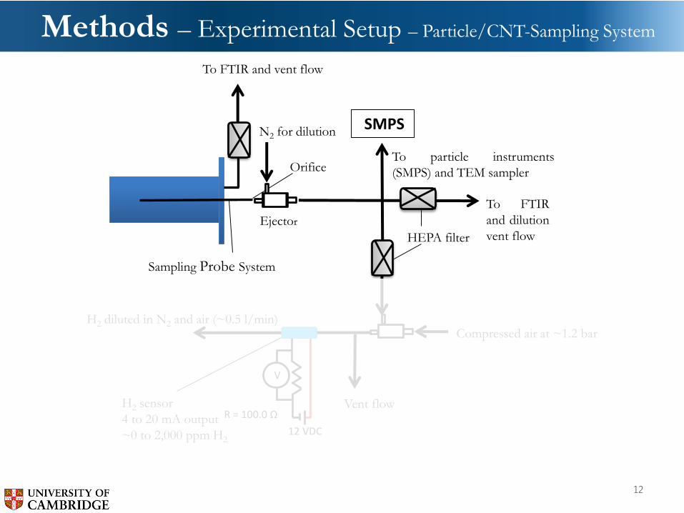
Methods – Experimental Setup – Particle/CNT-Sampling System
12
Vent flow
Orifice
Sampling Probe System
Tube furnace
H2 sensor
4 to 20 mA output
~0 to 2,000 ppm H2
N2 for dilution
To FTIR
and dilution
vent flowEjector
V
12 VDC
R = 100.0 Ω
To particle instruments
(SMPS) and TEM sampler
Compressed air at ~1.2 bar
HEPA filter
H2 diluted in N2 and air (~0.5 l/min)
To FTIR and vent flow
SMPS

500 ml/minRe~25<<2300
Results – Analysis along Tube Axis
13
Temperature distribution (Tmax~1500 K)
Wal
l T
emp
erat
ure
[K
]
Length of Tube [mm]
Reactor tube, 40 mm inner diameter,
length: 700 mm

Results – Analysis along Tube Axis
14
1
2
34
5
6
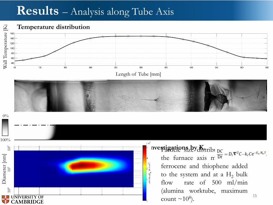
Results – Analysis along Tube Axis
15
Temperature distribution
Breakdown of ferrocene. Modelled based on Investigations by K.
Kuwana et al. and D. Conroy et al.
Wal
l T
emp
erat
ure
[K
]
Length of Tube [mm]
Dia
met
er [
nm
]10
0
10
110
2
Particle size distributions along
the furnace axis measured for
ferrocene and thiophene added
to the system and at a H2 bulk
flow rate of 500 ml/min
(alumina worktube, maximum
count ~108).
0%
100%
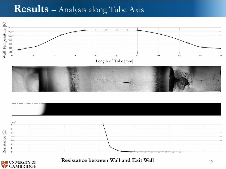
Results – Analysis along Tube Axis
16Resistance between Wall and Exit Wall
Wal
l T
emp
erat
ure
[K
]R
esis
tan
ce [
Ω]
Length of Tube [mm]

Results – Analysis along Tube Axis
17
7
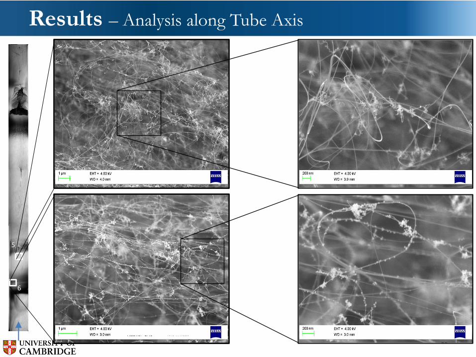
Results – Analysis along Tube Axis
18
5
6
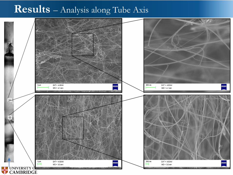
Results – Analysis along Tube Axis
19
3
4
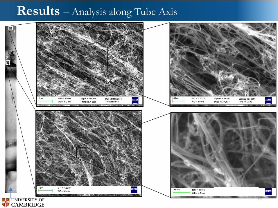
Results – Analysis along Tube Axis
20
1
2
Summary and Conclusions
• Introduction of CVD process that has the potential toproduce (oriented) CNTs at a rate and a pricecomparable to the production of synthetic amorphouscarbon.
• Particle appearance and disappearance observed in bothSEM images and SMPS measurements was shown.
• Catalyst nanoparticles stick to initially grown CNTs andmay act as a growing point of a new CNT.
• Different ‘quality’ of produced web was shown bymeans of SEM.
• During the synthesis process, CNTs mostly assembleinto bundles.
21

Outlook
22
Gaining optical access to the process …

Thank you…
23
Questions ?

Introduction – From Nanotube to Fiber
24

Results – Analysis along Tube Axis
25
Wal
l Te
mp
erat
ure
[K
]D
iam
ete
r [n
m]
10
0
1
01
10
2
Particle size distributions along thefurnace axis measured for ferroceneand thiophene added to the system andat a H2 bulk flow rate of 500 ml/min(alumina worktube).
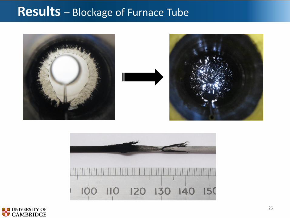
Results – Blockage of Furnace Tube
26

Results – Blockage of Furnace Tube – no Thiophene
27
• No ‘web’ growth at specific spot
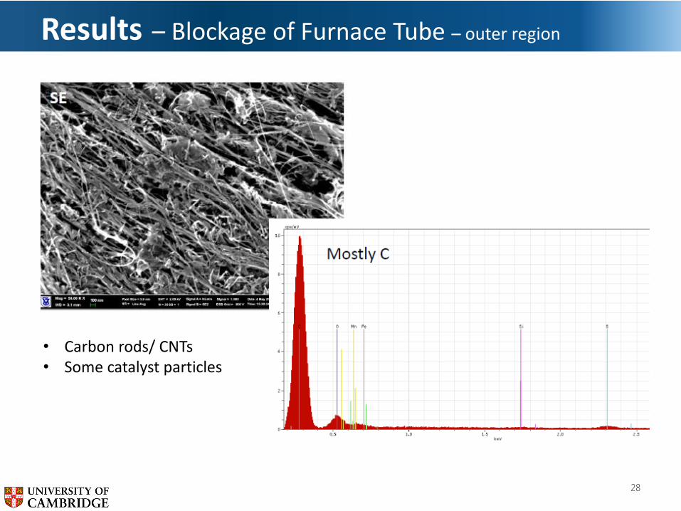
Results – Blockage of Furnace Tube – outer region
28
• Carbon rods/ CNTs• Some catalyst particles

Results – Blockage of Furnace Tube – inner region
29
• Carbon rods• No catalyst particles

Results – Blockage of Furnace Tube – inner region
30
• Carbon rods/ CNTs• Some catalyst particles