case study on identification, evaluation & repair of
TRANSCRIPT

International Journal of Engineering Technology, Management and Applied Sciences
www.ijetmas.com January 2017, Volume 5, Issue 1, ISSN 2349-4476
260 P.Suganthy, R.Gajendran
Case Study on Identification, Evaluation & Repair of Cracks in
Concrete Structures
P.Suganthy
Assistant Professor
Sri Ranganathar Institute of Engineering and
Technology,Coimbatore
R.Gajendran
Assistant Professor
Sri Ranganathar Institute of Engineering and
Technology,Coimbatore
ABSTRACT
Cracks are one kind of universal problem of concrete construction. It affects the building artistic and the functions and it
also destroys the wall’s integrity, even reduce the durability of structure. Therefore we should take some measures to
reduce and prevent the cracks. Some faulty steps during construction lead to different type of cracks on various
structural and non- structural parts of the building. Timely identification of such cracks and adopting preventive
measure are essential. The repair materials and repair techniques are different, depending upon the forms of cracks
according to their positions in structure. Some types of cracks seriously need attention as they are structurally
hazardous. In some cases, restorative work can cause more serious problems and extend the results to be more cracking
and more make damage in the buildings. In this project, we have discussed about the cracking after construction and
rebar technique adopted to overcome it.
Keywords
Structure Safety, Durability of Structure, Cracks, Repair materials and Repair techniques.
INTRODUCTION
A crack is a complete or incomplete separation of concrete into two or more parts produced by breaking or
fracturing. It destroys the wall’s integrity, affects the structure safety even reduce the durability of structure.
Cracks develop due to deterioration of concrete or corrosion or reinforcement bars due to poor construction or
inappropriate selection of constituent material and by temperature and shrinkage effects. Cracking can occur
in hardened and fresh, or plastic, concrete as a result of volume changes and repeated loading. Active cracks
may require more complex repair procedures that may include eliminating the actual cause of the cracking in
order to ensure a successful long-term repair. Failure to address the underlying cause may result in the crack’s
repair being short-term, making it necessary to go through the same process again. Cracks’ sizes range from
micro-cracks that expose the concrete to efflorescence to larger cracks caused by external loading conditions.
Noting cracks’ sizes shapes and locations can aid in determining their initial causes. The stress-strain response
of concrete is closely associated with the formation of micro cracks, that is, cracks that form at coarse-
aggregate boundaries (bond cracks) and propagate through the surrounding mortar (mortar cracks).
STRUCTURAL CRACKS
These cracks occur due to incorrect design, faulty construction or overloading and these may endanger the
safety of a building. Structural cracks are of important and have to be dealt more carefully because neglect to
this leads to unsafe structure. Structural cracks are due to poor construction sites, swollen soil, poor soil
bearing or overloading. For Example as we see in the ground floor of Block of A, in the western side of room
no A001, structural cracks started to appear (Figure 1) these cracks are usually accompanied by other signs of
foundation issues such as sticking doors and windows, slanted doors, sloping floors and cracks in porches.
The common characteristics of structural cracks include:
Continuous horizontal cracks along walls

International Journal of Engineering Technology, Management and Applied Sciences
www.ijetmas.com January 2017, Volume 5, Issue 1, ISSN 2349-4476
261 P.Suganthy, R.Gajendran
Vertical cracks that are wider at the top or bottom
Stair-step cracks
Foundation wall cracks
Cracks in beams, foundation slabs
Angled cracks that form in the corners of walls with a horizontal crack in the center
Cracks wider than 1/8"
Cracks extending to the upper levels of the home
Figure 1 Figure 2
To control this, Rebar technique is adopted in stages,which is shown in Figure 3, Figure 4. Rebar also known
as reinforcing steel, reinforcement steel, is a steel bar or mesh of steel wires used as a tension device in
reinforced concrete and reinforced masonry structures to strengthen and hold the concrete in tension. Rebar's
surface is often patterned to form a better bond with the concrete. Concrete is a material that is very strong in
compression, but relatively weak in tension. To compensate for this imbalance in concrete's behavior, rebar is
cast into it to carry the tensile loads. Most steel reinforcement is divided into primary and secondary
reinforcement.
Figure 3 Figure 4
NON-STRUCTURAL CRACKS
Non Structural cracks occur mostly due to internally induced stresses in building materials. These cracks
normally do not endanger the safety but may look unsightly, create an impression of faulty work or give a
feeling of instability. These are mostly due to internally induced stresses in buildings materials and do not
endanger safety of a building but may look unsightly, or may create an impression of faulty work or may give
a feeling of instability. In some situations due to penetration of moisture through them non-structural cracks

International Journal of Engineering Technology, Management and Applied Sciences
www.ijetmas.com January 2017, Volume 5, Issue 1, ISSN 2349-4476
262 P.Suganthy, R.Gajendran
may spoil the internal finishes thus adding to the cost of maintenance, or corrode the reinforcement, thereby
adversely affecting the stability of the Structure in long run.
Non-structural cracks started to appear as in Figure 5.
Figure 5
Controlling measures such as Portland cement grouting can be taken. Wide cracks, particularly in gravity
dams and thick concrete walls, may be repaired by filling with Portland cement grout. This method is effective
in stopping water leaks, but it will not structurally bond cracked sections. The procedure consists of cleaning
the concrete along the crack; installing built-up seats (grout nipples) at intervals astride the crack (to provide a
pressure tight connection with the injection apparatus); sealing the crack between the seats with a cement
paint, sealant, or grout; flushing the crack to clean it and test the seal; and then grouting the whole area. Grout
mixtures may contain cement and water or cement plus sand and water, depending on the width of the crack.
Figure 6
Drying shrinkage
After hardening, concrete begins to shrink as water not consumed by cement hydration leaves the system. This
is known as drying shrinkage. Water above that necessary to hydrate cement is required for proper workability
and finish ability – the water is called “water of convenience.” In general, the higher the additional water
content, the higher the shrinkage potential. For small, unrestrained concrete specimens (prisms), a low
ultimate shrinkage (strain) is considered to be less than 520 millionths (at 50 percentage relative humidity and
[73 degrees Fahrenheit]). Typical concrete shrinkage has been measured at 520 to 780 millionths. However,
for some mixtures, shrinkage exceeding 1,100 millionths has been documented. Using concrete with a higher
drying shrinkage increases the risk of problems with the floor performance.
Drying shrinkage cracks started to appear as in Figure 7.

International Journal of Engineering Technology, Management and Applied Sciences
www.ijetmas.com January 2017, Volume 5, Issue 1, ISSN 2349-4476
263 P.Suganthy, R.Gajendran
Figure 7
Controlling measures such as Dry packing can be chosen, Dry packing is the hand placement of a low water
content mortar followed by tamping or ramming of the mortar into place, producing intimate contact between
the mortar and the existing concrete. Because of the low water-cement ratio of the material, there is little
shrinkage, and the patch remains tight and can have good quality with respect to durability, strength, and
water tightness. To minimize shrinkage in place, the mortar should stand for 1/2 hour after mixing and then
should be remixed prior to use. The mortar should be placed in layers about 3/8 in. (10 mm) thick. Each layer
should be thoroughly compacted over the surface using a blunt stick or hammer, and each underlying layer
should be scratched to facilitate bonding with the next layer. The repair should be cured by using either water
or a curing compound. The simplest method of moist curing is to support a strip of folded wet burlap along the
length of the crack.
Figure 8
CRACK DUE TO THERMAL PROBLEMS
External seasonal temperature variations
In thicker sections, the internal temperature rises and drops slowly, while the surface cools rapidly to ambient
temperature. Surface contraction due to cooling is restrained by the hotter interior concrete that doesn’t
contract as rapidly as the surface. This restraint creates tensile stresses that can crack the surface concrete as a
result of this uncontrolled temperature difference across the cross section. In most cases thermal cracking
occurs at early ages. In rare instances thermal cracking can occur when concrete surfaces are ex-posed to
extreme temperature rapidly.
External seasonal temperature variations cracks started to appear as in Figure 9:

International Journal of Engineering Technology, Management and Applied Sciences
www.ijetmas.com January 2017, Volume 5, Issue 1, ISSN 2349-4476
264 P.Suganthy, R.Gajendran
Figure 9
Remedial measures can be taken as Epoxy injection method. The technique generally consists of establishing
entry and venting ports at close intervals along the cracks, sealing the crack on exposed surfaces, and injecting
the epoxy under pressure. Epoxy injection has been successfully used in the repair of cracks in buildings,
bridges, dams, and other types of concrete structures (ACI 503R). However, unless the cause of the cracking
has been corrected, it will probably recur near the original crack.
Figure 10
CRACK DUE TO STRUCTURAL PROBLEMS
Accidental overload
The cross section of concrete is designed with both calculated and estimated loads, determined from building
codes. Design includes such factors as the strength of the concrete, the number, sizing, and placement of
reinforcing bars, and size and shape of the concrete cross section. When a structure is overloaded to the extent
not covered in safety factors, concrete may be damaged or fail. Overloading may be in shear, flexure, or
tension, or may be a result of fatigue or cyclic loading.
Accidental overload cracks started to appear as in Figure 11:
Figure 11

International Journal of Engineering Technology, Management and Applied Sciences
www.ijetmas.com January 2017, Volume 5, Issue 1, ISSN 2349-4476
265 P.Suganthy, R.Gajendran
Remedial measures can be taken as Conventional reinforcement,cracked reinforced concrete have been
successfully repaired by inserting reinforcing bars and bonding them in place with epoxy. This technique
consists of sealing the crack, drilling holes that intersect the crack plane at approximately 90 degree, filling the
hole and crack with injected epoxy and placing a reinforcing bar into the drilled hole. Typically, No. 4 or 5
(10 M or 15 M) bars are used, extending at least 18 in. (0.5 m) each side of the crack. The reinforcing bars can
be spaced to suit the needs of the repair. They can be placed in any desired pattern, depending on the design
criteria and the location of the in-place reinforcement.
CRACKS DUE TO PLASTIC PROBLEMS
Plastic shrinkage
Plastic shrinkage cracks typically occur on horizontal surfaces exposed to the atmosphere. These cracks are
different from other early cracks becausethey are deeper and wider. Plastic shrinkage cracks are typically two
to four inches deep and approximately one-eighth inch wide. They may also extend several feet in length
adopting a crow’s-foot pattern. These cracks form before any bond has developed between the aggregate
particles and mortar. Therefore, the cracks tend to follow the edges of large aggregate particles or reinforcing
bars and never break through the aggregate particles. Although plastic shrinkage cracks usually do not impair
the structural performance of the slab, cracks in some building floors have been blamed for leakage.
Plastic shrinkage cracks started to appear as in Figure 12
Figure 12
Remedial measures can be taken Epoxy injection method. The technique generally consists of establishing
entry and venting ports at close intervals along the cracks, sealing the crack on exposed surfaces, and injecting
the epoxy under pressure. Epoxy injection has been successfully used in the repair of cracks in buildings,
bridges, dams, and other types of concrete structures (ACI 503R). However, unless the cause of the cracking
has been corrected, it will probably recur near the original crack.
Figure 13
MICRO CRACKS
They are usually very fine voids caused by large capillary pores resulting from the use of low grades
(strength) of concrete with high water to cement ratio. They could also occur due to addition of excess water
International Journal of Engineering Technology, Management and Applied Sciences
www.ijetmas.com January 2017, Volume 5, Issue 1, ISSN 2349-4476
266 P.Suganthy, R.Gajendran
or high water to cement ratio of concrete mix. Fine cracks are generally present in concrete and can occur due
to various reasons. They do not pose a serious threat to concrete deterioration initially as they are generally
not deep and are discontinuous. With lapse of time due to variations in temperatures, changes in weather
conditions, changes in loading conditions they increase in depth, length and width and combine with other
fine cracks to create continuous passage for moisture, chlorides, sulphates and other chemicals from the
environment to enter and start corrosion of steel in concrete and other deleterious reactions.
Micro cracks started to appear as in Figure 14:
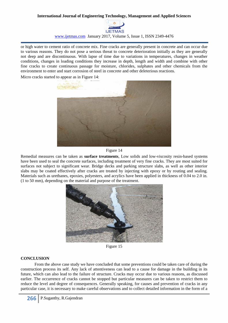
Figure 14
Remedial measures can be taken as surface treatments, Low solids and low-viscosity resin-based systems
have been used to seal the concrete surfaces, including treatment of very fine cracks. They are most suited for
surfaces not subject to significant wear. Bridge decks and parking structure slabs, as well as other interior
slabs may be coated effectively after cracks are treated by injecting with epoxy or by routing and sealing.
Materials such as urethanes, epoxies, polyesters, and acrylics have been applied in thickness of 0.04 to 2.0 in.
(1 to 50 mm), depending on the material and purpose of the treatment.
Figure 15
CONCLUSION
From the above case study we have concluded that some preventions could be taken care of during the
construction process its self. Any lack of attentiveness can lead to a cause for damage in the building in its
future, which can also lead to the failure of structure. Cracks may occur due to various reasons, as discussed
earlier. The occurrence of cracks cannot be stopped but particular measures can be taken to restrict them to
reduce the level and degree of consequences. Generally speaking, for causes and prevention of cracks in any
particular case, it is necessary to make careful observations and to collect detailed information in the form of a

International Journal of Engineering Technology, Management and Applied Sciences
www.ijetmas.com January 2017, Volume 5, Issue 1, ISSN 2349-4476
267 P.Suganthy, R.Gajendran
checklist with regards to the following aspects as may be relevant to a particular case. Better understanding of
the causes of cracks one may be able to avoid major structural catastrophes.
REFERENCES [1] Kazem Reza Kashyzadeh, NedaAghiliKesheh. Study type of Cracks in construction and its controlling. Volume 2,
Issue 8, August 2012, PP 528-531.
[2] IS 456:2000, “Indian Standard of Plain and Reinforced Concrete Code of Practice”.
[3] Hand book HB 84-2006: Guide to Concrete Repair and Protection, A joint publication of ACRA, CSIRO and
Standards Australia.
[4] KishorKunal, NameshKillemsetty. Study on control of cracks in a Structure through Visual Identification &
Inspection. Volume 11, Issue 5 Ver. VI, PP 64-72.
[5] RytisSkominas, VincasGurskis, AlgimantasPatasius. Research of material suitability for crack repair in reinforced
concrete structures. 4th International Conference CIVIL ENGINEERING`13.
[6] Syed MohdMehndi, Prof. Meraj Ahmad Khan & Prof. Sabih Ahmad. Causes and evaluation of cracks in concrete
structures. Volume 2, Issue 5, PP. 29-33.