case study: challenges of a single-layer reticulated …
TRANSCRIPT

CASE STUDY: CHALLENGES OF A SINGLE-LAYER RETICULATED DOME
Naveed Anwar, Pramin Norachan, Thaung Htut Aung
AIT Consulting, Asian Institute of Technology, Bangkok, Thailand

2
Thailand and Buddhist Temples
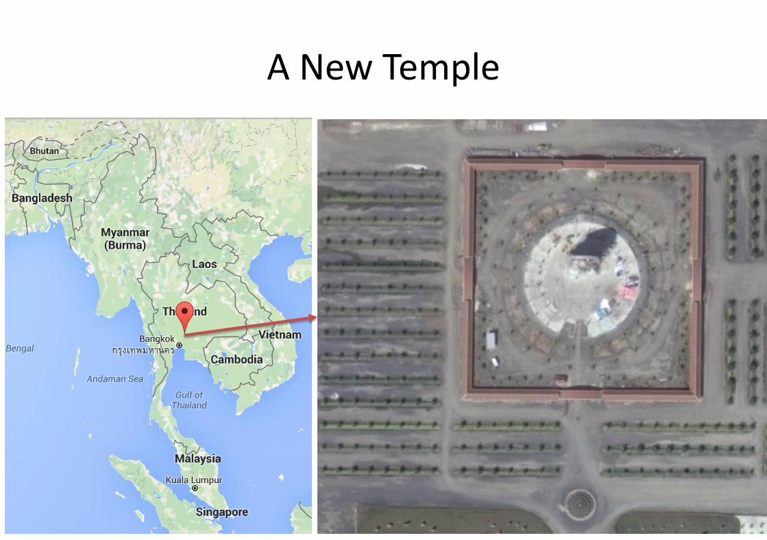
A New Temple

Buddhist Monks
4

5The dome is used to cover a tall Buddha statue located in Saraburi, Thailand

The Challenges
• The form is pre-decided and is not the most efficient
– Not spherical, not parabolic, but a combination
• The sub structure was already constructed by the time we were engaged
– The foundations
– The ring columns
• The height is governed by the height of the statue, already under construction
• Client had already purchased tones steel pipes of 260 diamm of 4.5 mm thickness

7
Structural System
Single layer, reticulated shell, made from steel pipes

8
FINITE ELEMENT MODELING
RC base structure
Steel dome structure
• The structure was already completed up to columns.• The RC columns and beams were modelled as linearly
elastic members using frame element.• The RC slabs were modelled as linearly elastic shell
elements.
• The steel circular pipes were modelled by using frame elements.
• The cladding areas were modelled by using shell elements with modification of stiffness in order to transfer only loads without contributing any stiffness.

9
MODAL ANALYSIS
• The first two modes are pure translation in horizontal direction, respectively due to symmetrical configuration of the structure as expected.
• The third mode is vertical vibration, while the fourth mode performs in twisting.

10
MODAL ANALYSIS
• After the fifth mode, it is found that the steel dome structure starts to vibrate with the local vibration in various patterns.
11
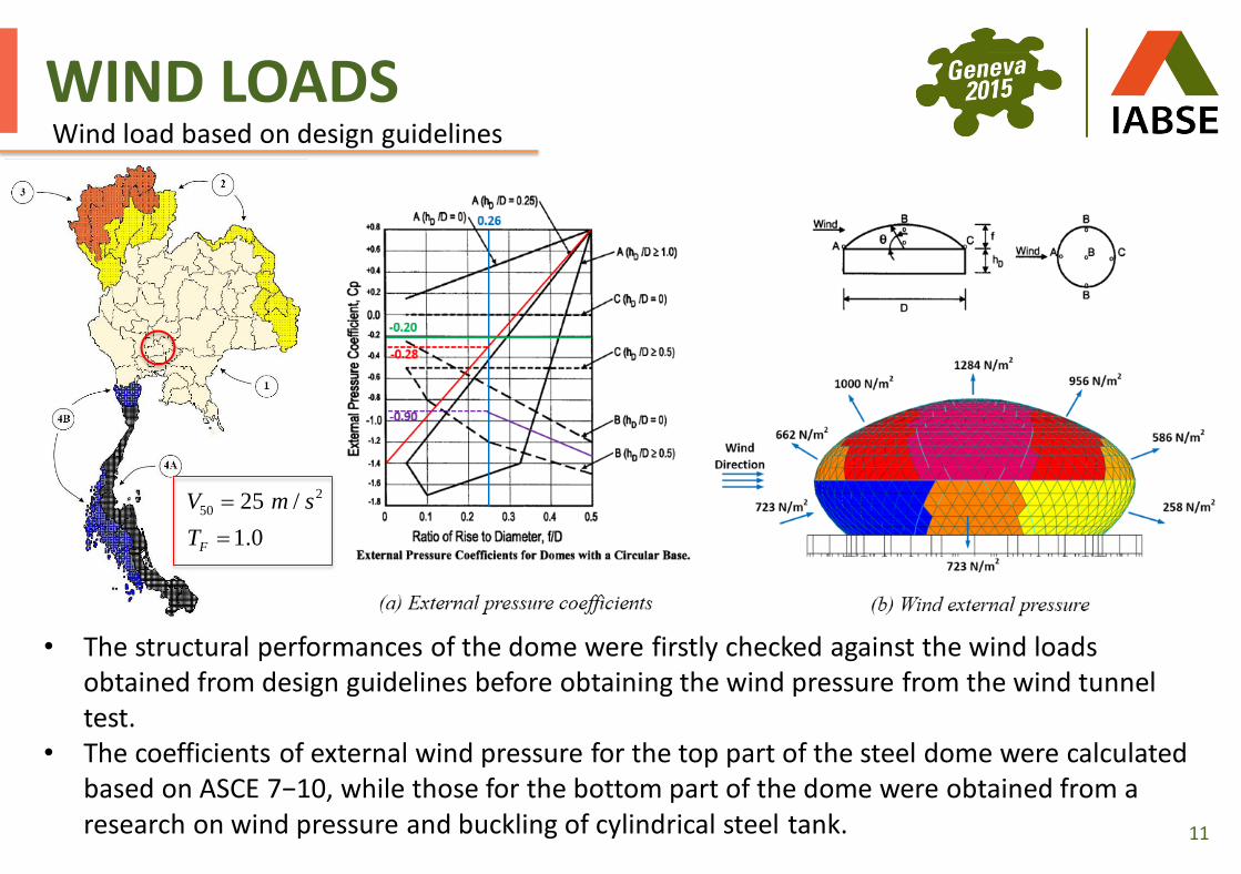
WIND LOADS Wind load based on design guidelines
• The structural performances of the dome were firstly checked against the wind loads obtained from design guidelines before obtaining the wind pressure from the wind tunnel test.
• The coefficients of external wind pressure for the top part of the steel dome were calculated based on ASCE 7−10, while those for the bottom part of the dome were obtained from a research on wind pressure and buckling of cylindrical steel tank.
2
50 25 /
1.0F
V m s
T

12
WIND LOADS Wind load based on wind tunnel test
To obtain more accurate wind pressure acting on the dome structure, wind study of the dome structure was performed by TU-AIT wind tunnel test.

13
WIND LOADS Wind load based on wind tunnel test
• The scaled model exposed to approaching wind was rotated by direction basis for 36 directions at 10 degree intervals.
• Due to symmetry of the dome geometry, the structural analysis was performed under one direction of wind.
• The time-history pressure at 79 locations were scaled up and assigned to the finite element model in SAP2000 for evaluation of the dynamic responses.
• The sample time-history pressures at the different locations on the dome surface are illustrated in the figure.

14
DEFORMATIONS AND DIAPLACEMENTS
• The deformation shapes under wind pressure obtained from wind tunnel test at a time step are illustrated in the figure.
• As expected, the results shows that the upward deformation are observed at the top of the dome due to the suction pressure at this region, while pushing pressure can be observed at the surface that directly resist wind load.
Deformation of the structure under wind obtained from the wind tunnel test
suction
pushing

15
SEISMIC LOADS
• Earthquake load was obtained from the Thai seismic calculation guideline DPT 1302−52.
• The response spectra at the design basis earthquake level (DBE) for 475 year return period (10% of probability of exceedance in 50 years) was used in this evaluation with the importance factor (I=1.25) and the response modification factor (R=1).
0.00
0.02
0.04
0.06
0.08
0.10
0.12
0 1 2 3 4 5 6
Spec
tral
Acc
eler
atio
n, S
a (g
)
Period (s)
16
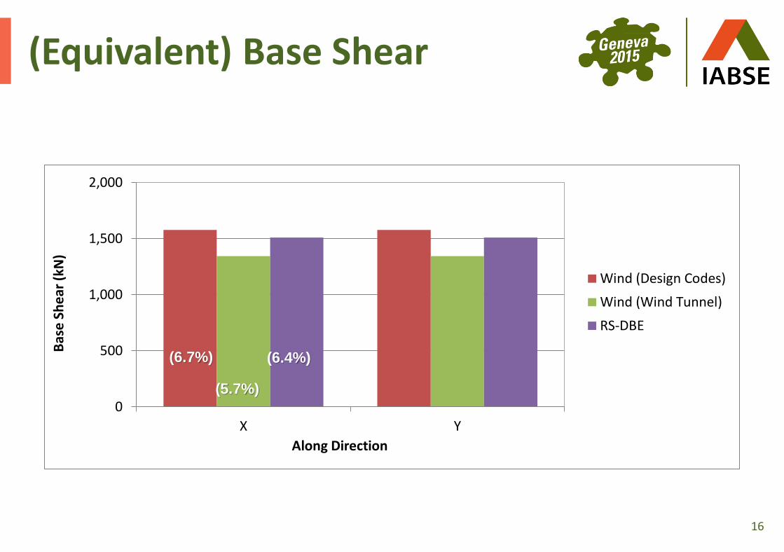
(Equivalent) Base Shear
0
500
1,000
1,500
2,000
X Y
Bas
e S
he
ar (
kN)
Along Direction
Wind (Design Codes)
Wind (Wind Tunnel)
RS-DBE
(5.7%)
(6.7%) (6.4%)

17
DEFORMATIONS AND DIAPLACEMENTS
• It is found that the maximum lateral displacements is approximate 3.6 cm which is less than the limit 20 cm (H/200 = 40 × 100/200).
• The maximum vertical displacements at the top of the dome is about 6.1 cm which is within the limit 17.9 cm (L/480 = 86 × 100/480).
Maximum displacements under lateral and vertical loads

18
Staged Construction Analysis
1st Stage 2nd Stage 3rd Stage 3rd Stage (to be continued)
4th Stage 4th Stage (to be continued) 5th Stage 6th Stage
Stages Construction Activities
1 Build RC circular base structure including piles, foundations, columns, beams, and slabs
2 Construct the bottom part of the super steel dome supported by using steel frame shoring
3 Install a set of steel cells until completing the first ring of the top part of the super steel dome
4 Repeat the stage 3 until fishing the top part of the super steel dome
5 Remove the steel frame shoring from the bottom part of the super steel dome
6 Install cladding throughout the super steel dome

19
STEEL CIRCULAR PIPES
• The 267.4 mm (10 inch) steel circular pipes with thickness 4.5 and 6.0 mm were used to be the primary components of the single-layer steel dome structure.
• The performances of these steel members, such as PMM interaction, axial tension, axial compression, moment and shear were evaluated against demand forces.
• The member PMM demand over capacity D/C ratio provided the highest value of 0.61 among the other D/C ratios.
• Thus, the steel circular pipes with these sections have sufficient capacities to resist the demand forces.

20
STEEL DOME SUPPORTS
To avoid the stress concentration and excessive moment at the supports between the steel dome structure and the ring beam under gravity and lateral loads, the pin-connected support was presented to release the excessive demand forces.

21
STEEL DOME CONNECTIONS
• At the intersection of the pipes, steel circular joint was proposed in order to make construction easy and convenient.
• The steel circular joint consists of steel ring plate, inner diaphragm and cover plate. For building this joint, the first part using three steel pipes are connected with the circular steel ring and inner diaphragms by welding, while the second part is combined by welding the other three steel pipes with steel cover plate.
• Finally, both parts are assembled by using bolts.

22
STEEL DOME CONNECTIONS

23
CONCLUSIONS
• A structural system was developed and optimized to fit the tight constraints of form and existing sub-structure and available materials
• Wind pressure time histories from wind tunnel test were applied to determine local wind induced response
• Constructing sequence carried out to reduce the need for falsework
• Minor retrofitting of columns was needed to accommodate the lateral loads