cascade delivery system
TRANSCRIPT

85.2639.00 Rev F
Cascade® Delivery System
Instructions for Use

Copyright
© 2015 A-dec Inc. All rights reserved.
A-dec Inc. makes no warranty of any kind with regard to this material, including, but not limited to, the implied warranties of merchantability and fitness for a particular purpose. A-dec Inc. shall not be held liable for any errors contained herein or any consequential or other damages concerning the furnishing, performance or use of this material. The information in this document is subject to change without notice. If you find any problems in the documentation, please report them to us in writing. A-dec Inc. does not warrant that this document is error-free.
No part of this document may be copied, reproduced, altered, or transmitted in any form or by any means, electronic or mechanical, including photocopying, recording, or by any information storage and retrieval system, without prior written permission from A-dec Inc.
Trademarks and Additional Intellectual Property Rights
A-dec, the A-dec logo, A-dec 500, A-dec 300, Cascade, Cascade Master Series, Century Plus, Continental, Decade, ICX, ICV, Performer, Preference, Preference Collection, Preference ICC, and Radius are trademarks of A-dec Inc. and are registered in the United States and other countries. A-dec 400, A-dec 200, Preference Slimline, and reliablecreativesolutions are also trademarks of A-dec Inc. None of the trademarks or trade names in this document may be reproduced, copied, or manipulated in any manner without the express, written approval of the trademark owner.
Certain touchpad symbols are proprietary to A-dec Inc. Any use of these symbols, in whole or in part, without the express written consent of A-dec Inc., is strictly prohibited.
Regulatory Information
Regulatory information mandated by agency requirements is provided in the Regulatory Information, Specifications, and Warranty document (p/n 86.0221.00), which is available in the Document Library at www.a-dec.com.
Product Service
Product service is available through your local authorized A-dec dealer. For service information, or to locate an authorized dealer, contact A-dec at 1.800.547.1883 in the USA and Canada or 1.503.538.7478 worldwide, or visit www.a-dec.com.

i
Warranty
Warranty:
Warranty information is provided in the Regulatory Information, Specifications, and Warranty document (p/n 86.0221.00), which is available in the Document Library at www.a-dec.com.

Glamour Shot of Product
Cascade Delivery System
ii
1 2 3 4 5 6 7 8
Cascade Delivery System(Traditional-Style Control Head with Unitized Holders)
Cascade Delivery System(Continental®-Style Control Head
with Touchpad and Push Button Arm Brake)
This document includes both styles of Cascade Delivery System, Continental and Traditional. Uses and adjustments are the same for both, except where noted.

iii
Cascade Delivery System
ContentsControls and Operation .................................................... 1Handpiece Actuation ........................................................ 1Drive Air Pressure Gauge ................................................. 1Arm Brake (Chair-Mounted Systems Only) .................. 2Foot Control ........................................................................ 2Handpiece Controls ........................................................... 3
Master Toggle ............................................................. 3Drive Air Pressure Controls ...................................... 4Coolant Air Flow Control .......................................... 5Coolant Water Flow Controls ................................... 6Handpiece Tubing Flush ........................................... 7
Handpiece Dry Block Conversion ................................... 8Oil Collector ........................................................................ 9Continental-Style Control Head Handpiece Whip Adjustment .......................................... 9Traditional-Style Control Head Holder Adjustments ........................................................ 10Footswitch and Touchpad (Optional) ......................11Programmable Chair Positions ...................................... 13Tray Holder (Optional) ................................................... 15
Tray Holder/Tray Arm Tension Adjustment ...... 16Autoclavable Syringe ...................................................... 17System Air and Water Pressure Adjustment ............... 17Care Instructions .............................................................. 17Flexible Arm ..................................................................... 18
Counterbalance Spring Adjustment ...................... 18Arm Stop Adjustment for L/R Conversion .......... 21
Continental-Style Control Positioning ......................... 22Trans-Thorax Positioning........................................ 22
Maintenance ..................................................................... 23Adjustments and Specifications .................................... 23

1
Cascade Delivery System
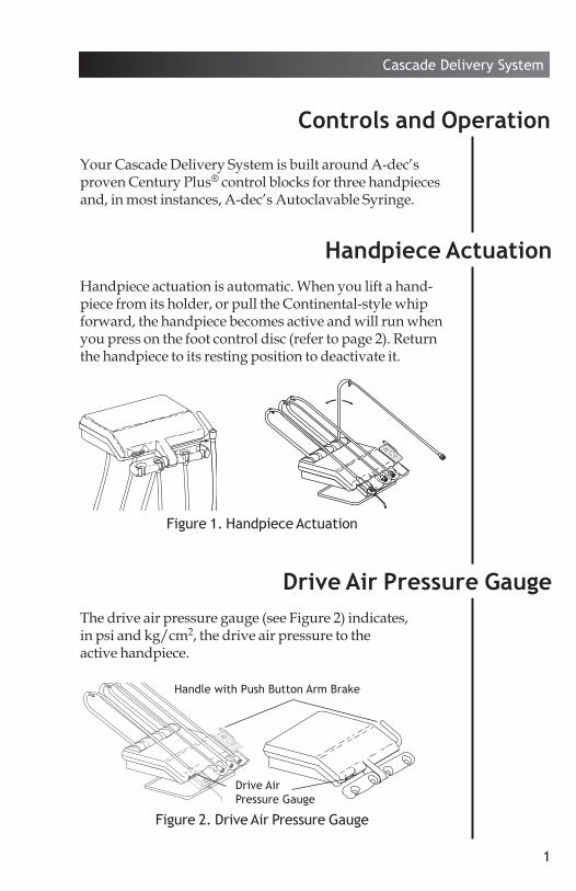
Your Cascade Delivery System is built around A-dec’s proven Century Plus® control blocks for three handpieces and, in most instances, A-dec’s Autoclavable Syringe.
Handpiece actuation is automatic. When you lift a hand-piece from its holder, or pull the Continental-style whip forward, the handpiece becomes active and will run when you press on the foot control disc (refer to page 2). Return the handpiece to its resting position to deactivate it.
The drive air pressure gauge (see Figure 2) indicates, in psi and kg/cm2, the drive air pressure to the active handpiece.
1 2 3 4 5 6 7 8
Figure 1. Handpiece Actuation
Figure 2. Drive Air Pressure Gauge
Handle with Push Button Arm Brake
Drive Air Pressure Gauge
Drive Air Pressure Gauge
Controls and Operation
Handpiece Actuation

2
Cascade Delivery System
The arm is braked against vertical movement until you press the arm brake button (see Figure 2 on page 1). You then are able to position the control head. Releasing the arm brake button locks the control head in place.
The foot control modulates drive air to the active handpiece and provides an air signal that activates the coolant air and coolant water flow. The foot control is operated by light foot pressure applied to any part of the foot control disc.
The foot control is equipped with a wet/dry toggle and can be equipped with an optional chip blower button (see Figure 3).
Wet/Dry Toggle. Allows you to shut off the coolant water to the handpiece without moving your hands from the oral cavity. Using your foot, move the toggle away from the blue dot to turn the coolant water off. Move the toggle toward the blue dot to turn the coolant water on.
Chip Blower Button. Sends a jet of air through the handpiece when it is not running.
Foot Control
Arm Brake
Chip Blower Button (Optional)
Foot Control Disc
Wet/Dry Toggle
Blue Dot (Water On)
Figure 3. Foot Control
(Chair-Mounted Delivery Systems Only)

3
Cascade Delivery System
Adjustment keys are provided for making adjustments to the recessed controls. You can order additional or replacement keys from your authorized A-dec dealer or use a 1/8" hex key.
The master toggle (see Figure 4) turns air, water, and electricity on or off to the system.
CAUTION The master toggle should be in the off (0) position whenever the unit is not in use. This will prevent the possibility of water damage should a leak occur while the unit is unattended. Making sure the unit is off will also prevent the possibility of self-ac-tivation and the resulting burn-out of your electrical accessories.
Handpiece Controls
1 2 3 4
I MASTER OPUSH
¨
Figure 4. Handpiece Controls
Handpiece Flush Control (see page 7)
Master Toggle (see below)
Drive Air Pressure Controls (see page 4)
Coolant Water Flow Controls (see page 6)
Coolant Air Flow Control (see page 5)
Master Toggle
Figure 5. Autoclavable Adjustment Key

4
Cascade Delivery System
The drive air pressure controls (see Figure 4 on page 3) are used to adjust the drive air pressure to each handpiece.
Adjust the drive air pressure to meet the handpiece manufacturer’s dynamic drive air pressure specification. Refer to the documentation that came with your hand-piece for the dynamic drive air pressure specification.
You will need a 3/32" hex key to complete this adjustment.
1. Install a bur in the handpiece. 2. Locate the drive air gauge on the front of the control
head (see Figure 2 on page 1). 3. Move the wet/dry toggle on the foot control
(see Figure 3 on page 2) to the off position, away from the blue dot).
4. Turn the drive air control clockwise until the valve seats.
5. Fully depress the foot control disc. 6. While running the handpiece, watch the drive air
gauge and adjust the handpiece dynamic drive air pressure to meet manufacturer’s specifications.• Turn the drive air control counterclockwise to
increase drive air pressure flow. • Turn the control clockwise to decrease flow.
7. Repeat steps 1 through 6 for each handpiece.
NOTE Do not turn the control counterclock-wise beyond the point where the drive air pressure no longer increases. The control adjustment screw may come completely out of the unit.
Drive Air Pressure Controls

5
Cascade Delivery System
The coolant air flow control is used to adjust the coolant air flow to all handpieces (see Figure 6).
You will need an adjustment key (see Figure 6) or a 1/8" hex key to complete this adjustment.
1. Install a bur in the handpiece. 2. Locate the coolant air control (see Figure 6). 3. Move the wet/dry toggle on the foot control (see
Figure 3 on page 2) to the off position, away from the blue dot.
4. Insert an adjustment key, or a 1/8" hex key, into the coolant air flow control.
5. Fully depress the foot control disc to activate the handpiece.
6. Adjust the coolant air flow to fit your needs. A strong flow of air is recommended. • Turn the control clockwise to decrease the flow.• Turn counterclockwise to increase the flow.
7. The coolant air has been set for all handpieces.
Coolant Air Flow Control
12
34
I MASTER O
PUSH
¨
12
PUSH
I
Figure 6. Coolant Air Flow Control
Adjustment Key (or 1/8" Hex Key)

6
Cascade Delivery System
The coolant water flow controls are used to adjust the flow of coolant water to each handpiece (see Figure 7).
You will need an adjustment key (see Figure 7) or a 1/8" hex key to complete this adjustment.
1. Install a bur in the handpiece. 2. Locate the coolant water flow controls (see Figure 7). 3. Move the wet/dry toggle on the foot control
(see Figure 3 on page 2) to the on position, toward the blue dot.
4. Insert an adjustment key, or a 1/8" hex key, into the coolant water flow control for the handpiece being adjusted.
5. Fully depress the foot control disc to activate the handpiece.
6. Adjust the coolant water flow to fit your needs. • Turn the control clockwise to decrease the flow.• Turn counterclockwise to increase the flow.
7. Repeat steps 1 through 6 for each handpiece.
Coolant Water Flow Controls
Figure 7. Coolant Water Flow Control
12
34
I MASTER O
PUSH
¨
12
PUSH
I
Adjustment Key (or 1/8" Hex Key)

7
Cascade Delivery System
The handpiece tubing flush system flushes more water through the tubings in less time than is normally possible when operating the foot control only. The hand pieces should not be connected when flushing the tubings.
How Often Should the Handpiece Tubings be Flushed?
The handpiece tubings should be flushed after each patient. Flush the tubings for about 20-30 seconds.
Flushing the Handpiece Tubings
Gather all the handpiece tubings that use coolant water and hold them over a sink, cuspidor bowl or basin. Be sure you hold the tubings so that the water will be directed away from you and into the receptacle (see Figure 8).
Insert an adjustment key or 1/8" hex key into the hand-piece tubing flush control on the side of the control head. Push in and hold the key for the appropriate time required, either for flushing between patients or flushing at the beginning of each day, depending on the situation. Remove the key and replace the tubings in their holders.
NOTE Discharge all tubing air and water lines for 20-30 seconds between each patient.
Handpiece Tubing Flush
Figure 8. Handpiece Tubing Flush
12
34
I MASTER O
PUSH
¨
1
PUSH
Adjustment Key

8
Cascade Delivery System
Your delivery system has three to four hand piece control blocks with coolant water to the handpiece. In some cases a control block without coolant water, a dry block, is required. If you require a dry block (offering no water to the handpiece) on your handpiece control system, a dry block conversion kit has been included with your system.
Dry Block Conversion Kit Installation
1. Move the master toggle to the off position. Bleed the system water by operating the syringe and flushing the handpiece tubings.
2. Locate the handpiece control block position that will be the dry block. Access the control blocks underneath the control head.
3. Use a 3/32" hex key to remove the large red cartridge from the control block. Install the large black cartridge from the dry block conversion kit into the control block (see Figure 9).
4. Use a 3/32" hex key to remove the small blue cartridge from the same control block. Install the small black cartridge from the dry block conversion kit into the control block.
5. Turn your handpiece control system on, then check the function of the dry block handpiece conversion. A small amount of residual water may be discharged from the handpiece tubing but should dry after a few seconds.
Handpiece Dry Block Conversion
Figure 9. Handpiece Dry Block Conversion
I MASTER O
Remove the red cartridge and replace with the large black cartridge.Remove the blue cartridge and
replace with the small black cartridge.
Do not remove the yellow cartridge.

9
Cascade Delivery System
The oil collector on your unit needs to be cleaned once a week for normal usage. Clean more often for heavier use.
1. Remove the oil collector jar from the unit and discard the old gauze (see Figure 10).
2. Fold a new two-inch square gauze pad into quarters and place it against the spring inside the jar.
3. Screw the oil collector jar onto the unit. Do not over tighten.
If your handpiece fails to actuate when the whip is pulled forward or it does not stop when the whip is in its resting position, the whip will have to be re-aligned. Contact your authorized A-dec Dealer to have the whip assembly aligned.
Continental-Style Control Head Handpiece Whip Adjustment
Oil Collector
Figure 10. Oil Collector
Gauze Pad
Control Head

10
Cascade Delivery System
The holder tension was set at the factory. However; if a holder is difficult to reposition or repositions too easily, the holder tension can be adjusted.
To adjust the holder tension:
• Loosen or tighten the tension adjustment screw (see Figure 11).
To reposition a holder:
• Rotate the holder to the desired angle.
Traditional-Style Control Head Holder Adjustments
Figure 11. Unitized Handpiece Holder
Rotate the holder full down to access the adjustment screw.
PUSH
1/8" Hex Key

11
Cascade Delivery System
Your A-dec dental chair is electronically controlled and hydraulically powered.
Chair functions are controlled by the footswitch or optional touchpad (see Figure 12 or 13).
Footswitch and Touchpad (Optional)
3
21
0
Figure 13. Chair Touchpad (Optional)
Base Up
Base Down
Back Up
Program Button
Programmable Position (2)
Cuspidor/Return (3)
Back Down
Programmable Position (1)
Programmable Entry/Exit (0)
1 2
30
Figure 12. Footswitch
Base Up
Back Down
Base Down
Back Up
Program Button
Programmable Position (1)
Programmable Position (2)
Programmable Entry/Exit (0) Cuspidor/Return (3)

12
Cascade Delivery System
Footswitch and Touchpad (Optional, Continued)
The chair LED indicates the status of the chair:
• ON: Normal operation.• SLOW BLINK: The cuspidor or stop plate limit
switches have been activated. Remove any obstruct-ing object.
The chair stop plate stops the chair immediately when any part of it is pressed. Should anything inadvertently become lodged under the chair, press Base UP on the footswitch or touchpad to raise the chair so the object can be removed. As long as pressure is applied to the stop plate, the chair base will not go down any further.
The footswitch (see Figure 12 on page 11) or the chair touchpad (see Figure 13 on page 11) gives you both manual and programmed control of chair positioning. The arrows on the footswitch and touchpad manually control chair back/toeboard tilt and chair lift. The numbered buttons are for Entry/ Exit and programmed chair positions.
Manual Controls
The Base Up/Down (lift) function controls chair lift, or vertical movement. To raise the chair, push the up arrow on the footswitch or touchpad. To lower the chair, push the down button on the footswitch or touchpad. Push the button until the chair reaches the desired height, then release it.
The Back Up/Down (tilt) function controls the chair back/toeboard tilt. To raise the chair back, push the right arrow on the footswitch or touchpad. To lower the chair back, push the left arrow on the footswitch or touchpad. Push the button until the chair back reaches the desired position, then release it.

13
Cascade Delivery System
Program Button
The Program Button (located on the top middle of the footswitch, or in between the arrows on the touchpad) is used to save the settings for Entry/ Exit (0), programmable positions (1 and 2), and Cuspidor/ Return (3).
Programmable Positions 1 and 2
NOTE When 1 or 2 are pressed on the foot-switch or touchpad, the chair base and back go to the preset position. To stop the chair at any point, press any chair button on the footswitch (or press any chair button on the touchpad).
To send the chair to a programmed operating position, push either 1 or 2 (or press 1 or 2 on the touchpad). Positions 1 and 2 are programmed at the factory to move the chair to the same position.
To change a programmable position, locate the program button on the foot switch or touchpad (see Figures 12 or 13 on page 11).
1. Using the manual arrows on the footswitch or touchpad, set the chair to the operating position that you prefer.
2. Press and release the program button. An audible tone will be emitted. Then, within four seconds, push the button for 1 or 2 to store that position. You will hear an audible tone confirming that the programmable function has been reprogrammed.
3. Check the programmed position by manually moving the chair to another position. Then push either 1 or 2 programmed in Step 2. The chair should move automatically to the position set in Step 1.
Programmable Chair Positions
14
Cascade Delivery System
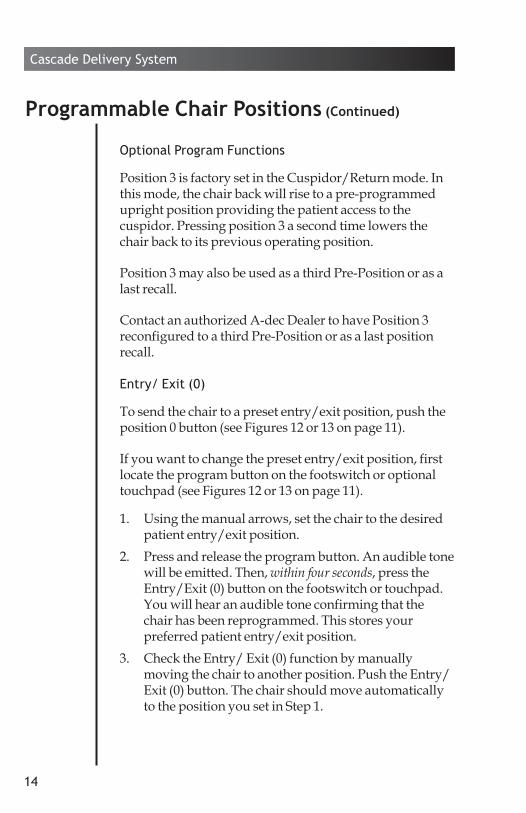
Optional Program Functions
Position 3 is factory set in the Cuspidor/Return mode. In this mode, the chair back will rise to a pre-programmed upright position providing the patient access to the cuspidor. Pressing position 3 a second time lowers the chair back to its previous oper ating position.
Position 3 may also be used as a third Pre-Position or as a last recall.
Contact an authorized A-dec Dealer to have Position 3 reconfigured to a third Pre-Position or as a last position recall.
Entry/ Exit (0)
To send the chair to a preset entry/exit position, push the position 0 button (see Figures 12 or 13 on page 11).
If you want to change the preset entry/exit position, first locate the program button on the footswitch or optional touchpad (see Figures 12 or 13 on page 11).
1. Using the manual arrows, set the chair to the desired patient entry/exit position.
2. Press and release the program button. An audible tone will be emitted. Then, within four seconds, press the Entry/Exit (0) button on the footswitch or touchpad. You will hear an audible tone confirming that the chair has been repro gram med. This stores your preferred patient entry/exit position.
3. Check the Entry/ Exit (0) function by manually moving the chair to another position. Push the Entry/ Exit (0) button. The chair should move automat ically to the position you set in Step 1.
Programmable Chair Positions (Continued)

15
Cascade Delivery System
For maximum flexibility in tray positioning, the optional tray holder can be rotated a full 360°, and the tray arm can be pivoted to either side. The tray holder should be adjusted so that it rotates easily, yet maintains its position while instruments are removed and replaced.
Figure 15. Tray Holder (Traditional-Style)
12
34
I MASTER O
PUSH
¨
Figure 14. Tray Holder (Continental-Style)
Tray ArmTray Holder
Tray Holder (Optional) (Not Available on All Delivery Systems)

16
Cascade Delivery System
To adjust the tray holder or tray arm, insert a 9/64" hex key through the appropriate mounting bracket (see Figures 14 or 15 on page 15). The hex key should protrude from the opposite side of the mounting bracket. If it does not, rotate the holder or arm until the key slides through the mounting bracket. While holding the bracket stationary, turn the holder or arm clockwise to increase the tension or counterclockwise to loosen the tension.
Figure 17. Tray Holder/Tray Arm Tension Adjustment (Traditional-Style)
12
34
I MASTER O
PUSH
¨
Tray Arm Mounting Bracket
Tray Holder Mounting Bracket
9/64" Hex Key
9/64" Hex Key
Tray Holder
Tray Holder/Tray Arm Tension Adjustment
Figure 16. Tray Holder/Tray Arm Tension Adjustment (Continental-Style)
9/64" Hex Key
Tray Holder Mounting Bracket
Mounting Bracket
Tray Holder
Tray Arm Mounting Bracket

17
Cascade Delivery System
To operate the syringe (see Figure 18):
• Move the master toggle to the on position.• Air – Press the right button down.• Water – Press the left button down.• Spray – Press both buttons down.
Refer to A-dec Syringes Instructions for Use (p/n 85.0680.00) for complete syringe operation and maintenance instructions.
For system air and water pressure adjustments, see the Floor Boxes Instructions for Use (p/n 85.2611.00).
For recommended asepsis instructions, see the A-dec E quipment Asepsis Guide (p/n 85.0696.00).
For recommended water system care, see the A-dec Self Contained Water System Instructions for Use (p/n 86.0609.00).
Autoclavable Syringe
System Air and Water Pressure Adjustment
Care Instructions
Figure 18. Autoclavable Syringe
Air Water Spray

18
Cascade Delivery System
Cascade delivery systems are available on A-dec’s flexible arm system. The flexible arm allows vertical and horizontal positioning of the control head to suit your practice.
The flexible arm contains a spring that counterbalances the weight of the control head. The arm also contains a friction mechanism to stabilize the arm at the upper and lower extremes of its vertical arc.
If the arm tends to rise or drop when the arm brake is released, the counterbalance spring needs adjustment.
1. Remove the flexible vinyl cover from the underside of the arm (see Figure 19). Gently pull the tubing and wiring in the arm slightly aside.
Flexible Arm
Counterbalance Spring Adjustment
Figure 19. Flex Arm Cover
Pull down on one end.

19
Cascade Delivery System
2. Raise the control head end of the flex arm until the friction adjustment socket head screw is accessible through the access hole in the arm (see Figure 20). Using a 5/32" hex key loosen, but do not remove, the friction adjustment screw.
3. Lift the control end of the flex arm as high as possible while turning the adjustment nut, this relieves the spring tension allowing the nut to turn more easily.• If the arm tends to drop, turn the spring tension
adjustment nut clockwise (as viewed from the con-trol head end of the arm, see Figure 21).
• If the arm tends to rise, turn the adjustment nut counterclockwise.
Figure 20. Tension Adjustment Locations
Friction Adjustment Screw
Spring Tension Adjustment Nut
Control Head
Counterbalance Spring Adjustment (Continued)
Spring Tension Adjustment Nut
Standard Screwdriver
Figure 21. Spring Tension Adjustment
Clockwise (If Arm Tends to Drop)Control Head Arm
Counterclockwise (If Arm Tends to Rise)

20
Cascade Delivery System
4. While adjusting the spring tension, frequently move the arm through its vertical arc to see if it is adjusted properly.
5. When you are satisfied with the spring tension adjustment, move the arm alternately full up and then full down positions releasing the control head at each position. If the arm drops or rises when you let go of it in either position, tighten the friction adjustment. Be careful not to over tighten the adjustment as you may damage the friction mechanism.
6. Reinstall the flex vinyl cover (see Figure 22). The cover is easily snapped back into place. Start by inserting one end of the cover into the arm and press it into place along the bottom of the arm.
Counterbalance Spring Adjustment (Continued)
Figure 22. Install the Flex Arm Cover

21
Cascade Delivery System
Lift the cap between the rigid arm and flexible arm (see Figure 23). Use a 3/32" hex key to remove the stop assembly. Rotate the flexible arm so the threaded hole is on the other side of the pin and reinstall the stop assembly.
Lift the cover, at the base of the rigid arm, from the top of the post box (see Figure 24). Use an 1/8" hex key to remove the stop assembly. Rotate the rigid arm so the threaded hole is in the opposite slot. Reinstall the stop assembly.
Arm Stop Adjustment for Left/Right Conversion
Figure 24. Rigid Arm Stop Adjustment
Rigid Arm
Cover
Use an 1/8″ hex key to remove.
Cap
3/32″ Hex Key
Flexible Arm
Figure 23. Flexible Arm Stop Adjustment
Rigid Arm

22
Cascade Delivery System
A-dec’s handpiece control and flexible arm system is designed to provide flexibility in positioning of the handpiece control.
The handpiece control and flexible arm system is configured for over-the-patient delivery at the factory.
Refer to Figure 25 when converting the handpiece control and flexible arm system for trans-thorax positioning.
1. Lift the cap at the top of the control head arm. 2. Use needle nose pliers to remove one of the pins
from the standard position and replace it in the hole nearest it. The pin moved will depend on if you are practicing right-hand or left-hand dentistry.
Continental-Style Control Positioning
Trans-Thorax Positioning
Figure 25. Trans-Thorax Positioning
Control Head Arm
Cap
Pins in the Standard Position Install pin, large
diameter down (shown in right-hand dentistry position).

23
Cascade Delivery System
Handpiece Tubing Flush ........................................page 7Oil Collector ...............................................................page 9Also refer to the following A-dec documents for more maintenance information:Autoclavable Syringe A-dec Syringes Instructions for Use .............85.0680.00Care Instructions A-dec Equipment Asepsis Guide ...................85.0696.00 A-dec Self Contained Water System Instructions for Use .......................................86.0609.00Power Supplies Floor Boxes Instructions for Use ...................85.2611.00
Handpiece Controls Drive Air Pressure ............................................page 4 (Refer also to your handpiece documentation for the manufacturer’s maximum dynamic drive air pressure specification.) Coolant Air Flow ..............................................page 5 Coolant Water Flow .........................................page 6 Continental-Style Handpiece Whip................page 9 Traditional-Style Handpiece Holder ............page 10Footswitch and Touchpad (Optional) ..................page 11Programmable Chair Positions .............................page 13Flexible Arm Adjustments Counterbalance Spring ...................................page 18 Arm Stop for Left/Right Conversion ...........page 21 Continental-Style Trans-Thorax Positioning...............................page 22
Adjustments and Specifications
Maintenance

24
Cascade Delivery System
Also refer to the following A-dec documentation for more adjustment and specification information:System Air and Water Pressure Adjustments Floor Boxes Instructions for Use ...................85.2611.00 Control Head Load Capacity: 10 lb (4.54 kg)—typical vertical load on tray to overcome the arm brake.
Service Requirements for Unit Operation: Minimum Air: 2.50 cfm (70.80 L/min) at 80 psi (551 kPa) Minimum Water: 1.50 gpm (5.68 L/min) at 40 psi (276 kPa) Minimum Vacuum: 12 cfm (339.84 L/min) at 8 inches of mercury (27 kPa)
NOTE Specifications are subject to change without notice. Some requirements may vary from country to country. For more information, contact your authorized A-dec dealer.
Adjustments and Specifications (Continued)


A-dec Headquarters2601 Crestview DriveNewberg, Oregon 97132United StatesTel: 1.800.547.1883 within USA/CANTel: +1.503.538.7478 outside USA/CANFax: 1.503.538.0276
A-dec AustraliaUnit 85-9 Ricketty StreetMascot, NSW 2020AustraliaTel: 1.800.225.010 within AUSTel: +61.(0).2.8332.4000 outside AUS
A-dec ChinaA-dec (Hangzhou) Dental Equipment Co., Ltd.528 Shunfeng Road Qianjiang Economic Development ZoneHangzhou 311106Zheijiang, ChinaTel: +1.503.538.7478
A-dec United KingdomAustin House, 11 Liberty WayNuneaton, Warwickshire CV11 6RZEngland Tel: 0800.ADEC.UK (2332.85) within UKTel: +44.(0).24.7635.0901 outside UK
85.2639.00 Rev FCopyright 2015 A-dec Inc.
All Rights Reserved.
ÍuÈ.Ç:GÈ.00JÎ