carte blanche - arduino workshop!ranjanmo/documents/arduino_tutorial.pdfcarte blanche - arduino...
TRANSCRIPT

Carte Blanche - Arduino Workshop!
NOTE: A portion of the educational content used in this guide is taken from the internet and the rest have been our efforts.
What is Arduino? Arduino is an open-source platform used for building electronics projects. Arduino consists of both a physical programmable circuit board (often referred to as a microcontroller) and a piece of software, or IDE (Integrated Development Environment) that runs on your computer, used to write and upload computer code to the physical board.
Why Arduino? The Arduino platform has become quite popular with people just starting out with electronics, and for good reason. Unlike most previous programmable circuit boards, the Arduino does not need a separate piece of hardware (called a programmer) in order to load new code onto the board – you can simply use a USB cable. Additionally, the Arduino IDE uses a simplified version of C++, making it easier to learn to program. Finally, Arduino provides a standard form factor that breaks out the functions of the micro-controller into a more accessible package.
What's on the board There are many varieties of Arduino boards that can be used for different purposes. Some boards look a bit different from the one below, but most Arduino

boards have a majority of these components in common
NOTE: The figure used is just for visual purposes, the actual board appearance may vary.
Power (USB / Barrel Jack)
Every Arduino board needs a way to be connected to a power source. The Arduino UNO can be powered from a USB cable coming from your computer or a wall power supply that is terminated in a barrel jack. In the picture above the USB connection is labeled (1) and the barrel jack is labeled (2).

The USB connection is also how you will load code onto your Arduino board. NOTE: Do NOT use a power supply greater than 20 Volts as you will overpower (and thereby destroy) your Arduino. The recommended voltage for most Arduino models is between 6 and 12 Volts.
Voltage Regulator
The voltage regulator (14) is not actually something you can (or should) interact with on the Arduino. But it is potentially useful to know that it is there and what it’s for. The voltage regulator does exactly what it says – it controls the amount of voltage that is let into the Arduino board. Think of it as a kind of gatekeeper; it will turn away an extra voltage that might harm the circuit. Of course, it has its limits, so don’t hook up your Arduino to anything greater than 20 volts.
Pins (5V, 3.3V, GND, Analog, Digital, PWM, AREF)
The pins on your Arduino are the places where you connect wires to construct a circuit (probably in conjunction with a breadboard and some wire. They usually have black plastic ‘headers’ that allow you to just plug a wire right into the board. The Arduino has several different kinds of pins, each of which is labelled on the board and used for different functions.
GND (3): Short for ‘Ground’. There are several GND pins on the Arduino, any of which can be used to ground your circuit.
5V (4) & 3.3V (5): As you might guess, the 5V pin supplies 5 volts of power, and the 3.3V pin supplies 3.3 volts of power. Most of the simple components used with the Arduino run happily off of 5 or 3.3 volts.
Analog (6): The area of pins under the ‘Analog In’ label (A0 through A5 on the UNO) are Analog In pins. These pins can read the signal from an analog sensor (like a temperature sensor) and convert it into a digital value that we can read.
Digital (7): Across from the analog pins are the digital pins (0 through 13 on the UNO). These pins can be used for both digital input (like telling if a button is pushed) and digital output (like powering an LED).
PWM (8): You may have noticed the tilde (~) next to some of the digital pins (3, 5, 6, 9, 10, and 11 on the UNO). These pins act as normal digital pins, but can also be used for something called Pulse-Width Modulation
(PWM). They have a specific use, but for now, think of these pins as being able to simulate analog output (like fading an LED in and out).
AREF (9): Stands for Analog Reference. Most of the time you can leave this pin alone. It is sometimes used to set an external reference voltage (between 0 and 5 Volts) as the upper limit for the analog input pins.
Reset Button Just like the original Nintendo, the Arduino has a reset button (10). Pushing it will temporarily connect the reset pin to ground and restart any code that is loaded on the Arduino. This can be very useful if your code doesn’t repeat, but you want to test it multiple times. Unlike the original Nintendo however, blowing on the Arduino doesn’t usually fix any problems. Reset follows active low logic.
Power LED Indicator Just beneath and to the right of the word “UNO” on your circuit board, there’s a tiny LED next to the word ‘ON’ (11). This LED should light up whenever you plug your Arduino into a power source. If this light doesn’t turn on, there’s a good chance something is wrong. Time to re-check your circuit!
TX RX LEDs TX is short for transmitter, RX is short for receiver. These markings appear quite a bit in electronics to indicate the pins responsible for serial communication. In our case, there are two places on the Arduino UNO where TX and RX appear – once by digital pins 0 and 1, and a second time next to the TX and RX indicator LEDs (12). These LEDs will give us some nice visual indications whenever our Arduino is receiving or transmitting data (like when we’re loading a new program onto the board).
Main IC The black thing with all the metal legs is an IC, or Integrated Circuit (13). Think of it as the brains of our Arduino. The main IC on the Arduino is slightly different from board type to board type, but is usually from the ATmega line of IC’s from the ATMEL company. This can be important, as you may need to know the IC type (along with your board type) before loading up a new program from the Arduino software. This information can usually be found in writing on the top side of the IC. If you want to know more about the difference between various IC’s, reading the datasheets is often a good idea.

Serial Communications IC. The small black square exactly below the USB connector is the serial communications IC, it takes care of all the serial communications with the computer and generates the required signals to facilitate the data transfer to the computer. Crystal. The small metal object placed on the board is the clock crystal which generates the clock pulses of required frequency for the timing related operations of the board the generally used frequency is 16Mhz. ISP Pins. These pins are used to load the boot loader to the chip, more about the pin will be discussed in the later part of this workshop.
ATmega -328 pin diagram

Interfacing.
Interfacing is the application part of Arduino or the way in which arduino can be
used to interact with the real world, this mostly involves connection of various
input/output devices to the arduino and their programming.
Types of interface devices
Input Devices
These devices which are mostly called as sensors help in bringing information
from the external environment to the device as input which can be used as basis
by the programmer to compute the output
some examples include-IR proximity sensor, IR remote sensor, ultrasonic sensor,
touch sensor, temperature sensor etc
Output Devices
These devices get the input from the arduino board and act accordingly they can
be either static devices like displays or indicators or they can be dynamic like
motors
Enough of Chitchat! Let’s get into business! ;)
Step 1 – Download and Arduino IDE(Integrated Development Environment) ZIP
File from the following link (http://arduino.cc/en/main/software) to your
computer and extract it. Then open the extracted folder and open the
arduino.exe to launch the Application. This how the IDE Window will appear when
you open it.

Step 2 - Install the CP210X serial communication driver
Step 3 – Connect the Arduino Board to the Computer using the USB cable and
select the appropriate COM Port.
Step 4 – Go to “Tools>Board” and select Arduino Deumilanove w/ ATmega328.
Step 5 – Go to “File>Examples>01.Basics>Blink” and upload the program!
Blink!!!

Coding in Arduino
Coding in arduino is fairly easy when any other platform is considered. It basically
consists of two parts
1. setup()
The contents in this portion will be executed only once so we would mostly
include contents like initialization and pin mode configuration in this.
2. loop()
The loop executes most of the code which we type. All the contents are
executed as an infinite loop till the board is reset. The reset button can be used
to restart the program.
Some common commands
1. pinMode(pin,type) -used to specify the type of pin (input/output)
2. digitalRead(data) -used to read data from digital pins
3. digitalWrite(pin,data) -used to write data to digital pins
4. analogRead(pin) -used to read data from analog pins. Returns a value in
the range 0 to 1023, Why?
__________________________________________________________________
5. analogWrite(pin,val) -used to write a PWM Signal to the specified analog O/P
pin. Takes an input value in the range 0 – 255. Why?
__________________________________________________________________

6. delay(duration) -used to generate a delay in milli second
7. Serial.begin(BaudRate) -used to start a serial communication of specified
baud rate
Various Baud Rates:__________________________________________
Difference between baud rate and bit rate?
_______________________________________________________________
8. Serial.read() -used to read incoming serial data
How does Serial.read() read incoming data? ________________________
9. Serial.print(data)-used to print data to serial monitor
10. HIGH -used to set logic 1
11. LOW -used to set logic 0

Interfacing LDR:
CODE:
int ldr;
void setup() {
ldr=0; //LDR is connected to Analog Input Pin 0
Serial.begin(9600);
}
void loop() {
int temp=analogRead(ldr); //Reads the value from the LDR
Serial.println(temp);
}

Interfacing Motors:
CODE:
int m,n,mv,nv;
void setup() {
m=10;
n=11;
nv=0;
mv=255;
analogWrite(n,nv);
analogWrite(m,mv);//
Writes a PWM Signal
with 100% Duty Cycle
}
void loop() {
mv--;
nv++;
if(mv==0) mv=255;
if(nv==255) mv=0;
analogWrite(n,nv);
analogWrite(m,mv);
delay(100);
}

Interfacing IR Sensors:
CODE:
int sensor=10;
void setup() {
pinMode(sensor,INPUT);
Serial.begin(9600);
}
void loop() {
if(digitalRead(sensor)) Serial.println("1");
else Serial.println("0");
}

Interfacing Relays WORKING:
CODE:
int state;
void setup () {
state = 0;
pinMode(17,OUTPUT);
}
void loop() {
state=!state; //Toggles the relay connected to pin 17
digitalWrite(17,state);
delay(3000);
}

LM35 Temperature Sensor:
CODE:
int pin; float temp; void setup() { pin=3; //LM35 is connected to Analog pin 3 Serial.begin(9600); } void loop() { /* analogRead(pin) reads a value in the range of 0 - 5 V from the Temperature Sensor(LM35) As the internal ADC uses 10 bits, there are a total of 1024 values that can be represented between 0 and 5000mV(5V). For a degree change in temperature, the output in the LM35 changes by 10mV */ temp=analogRead(pin)/1024.0*5000.0/10.0; Serial.println(temp); delay(400); }
TECHNICAL SPECIFICATIONS:
Supply Voltage: 4 to 30 V
Temperature Range: -55°C to +150°C
Accuracy: ±0.25°C At room temperature (25°C)
±0.75°C Full Range
Output Voltage Scale: 10mV/°C
CONNECTIONS:
LM35 <--> Arduino
+Vs <--- 4+ to +30V
Vout ---> Digital Pin in Arduino
GND <--> GND

Switch Interfacing:
MODES OF OPERATION:
CODE:
int led=3;
int sw=7;
int swst;
int ledst;
void setup() {
ledst=0;
pinMode(led,OUTPUT);
pinMode(sw,INPUT);
digitalWrite(sw,HIGH);
}
void loop() {
swst=digitalRead(sw);
if(swst==0) { //Checks if switch is
pressed
ledst=!ledst; //Changes led state
digitalWrite(led,ledst);
//Writes/Latches the new state of the
LED
while(digitalRead(sw)==0); //Traps
the program flow till the switch is
released
delay(300);
}
Arduino Digital
Pin
Arduino Digital
Pin
Active High Active Low

Arduino on Breadboard:
Atmega 328/168/88/8 with Arduino Bootloader.
Micro-controllers can be considered as a single chip computer designed to
perform a specific task. It consists of a lot of inner peripherals like Flash, RAM,
EEPROM, RTC etc which are used in executing the task.
Atmel AVR
The AVR is a modified Harvard Architecture based single chip 8-bit Micro-
controller developed in 1996 by Alf-Egil Bogen and Vegard Wollan. The name
AVR is derived from the name of the founders and is expanded as Alf-Egil
Bogen Vegard Wollan RISC microcontroller and is also called Advanced
Virtual RISC. The modified Harvard Architecture implemented in this chip is an
improved version of the original Harvard Architecture where separate
memories were employed for storing instructions and data, thus making both
simultaneously accessible unlike the Von Neumann architecture where both
were stored in the same memory thus increasing the CPU Complexity. These
micro-controllers have a RISC(Reduced Instruction Set Computing) CPU Design.
The usage of the word “reduced” does not refer to simplification or
optimization of instructions, it just refers to the reduction in the amount of
work done in a single instruction in comparison to the complex instructions of
the CISC(Complex Instruction Set Computing) Design. The term “8-bit” is used
to signify that the micro-controller is capable of operating 8-bit data and its
input and output registers are of 8-bits in size. On implementing an instruction
the AVR microcontroller stores the operands(data), operator(instruction) and
the result in separate registers.
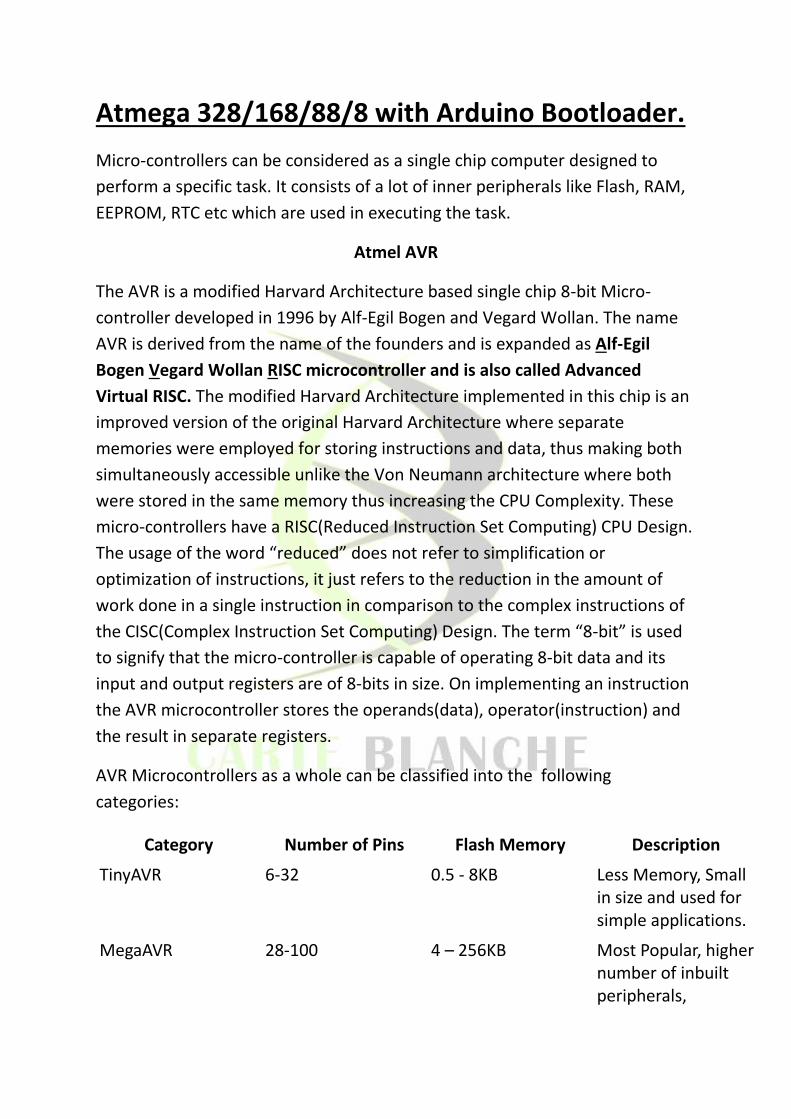
AVR Microcontrollers as a whole can be classified into the following
categories:
Category Number of Pins Flash Memory Description
TinyAVR 6-32 0.5 - 8KB Less Memory, Small in size and used for simple applications.
MegaAVR 28-100 4 – 256KB Most Popular, higher number of inbuilt peripherals,

Memory upto 256KB and used for moderate applications.
XMegaAVR 44-100 16 - 384KB Large amount of memory and is used commercially for largescale applications.
Arduino Platform
Arduino is an open-source electronic prototyping platform which mainly makes
use of MegaAVR Micro-controllers to interface external peripherals(Sensors,
Output devices etc). The Arduino Board is nothing but a collection of
components like LED's, LDR and RTC(Real Time Clock) etc attached on a single
board for easier interfacing with those components using the Micro-controller,
mainly used for Learning and Testing Purposes. Given below is a list of 28 pin
Atmega microcontrollers compatible with Arduino and their features :
Device ATmega8/8A 88/88P 168/168P 328/328P
Flash (bytes) 8192 8192 16384 32768
SRAM 1024 1024 1024 2048 EEPROM 512 512 512 1024
Max Freq (MHz) 16 20 20 20 Vcc (Supply Voltage) 2.7 to 5.5 1.8 to 5.5 1.8 to 5.5 1.8 to 5.5
Flash
Program instructions are stored in non-volatile flash memory. Although the Microcontrollers are 8-bit, each instruction takes one or two 16-bit words. The size of the program memory is usually indicated in the naming of the device itself (e.g., the ATmega64x line has 64 kB of flash while the ATmega32x line has 32 kB).
SRAM
Static random-access memory is a type of volatile semiconductor memory used for temporary storage of data buffers.

EEPROM
Electrically Erasable Programmable Read-Only Memory and is a type of non-volatile memory used to store data even when the device is powered off.
Burning a Bootloader to ATmega 328:
Arduino

Steps: