carnot cycle for mechanical engineers
DESCRIPTION
University of Oklahoma Design of Thermal Fluid System NotesTRANSCRIPT
WMM
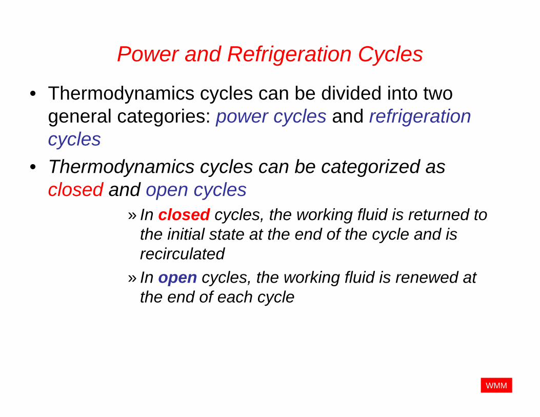
Power and Refrigeration Cycles
• Thermodynamics cycles can be divided into two general categories: power cycles and refrigeration cycles
• Thermodynamics cycles can be categorized as closed and open cycles
» In closed cycles, the working fluid is returned to the initial state at the end of the cycle and is recirculated
» In open cycles, the working fluid is renewed at the end of each cycle
WMM
Power Cycles
• Steam power plants are commonly referred to as » Coal plants » Nuclear plants» Natural gas plants
• Steam is the most common working fluid used in vapor power cycles because of its many desirable characteristics, such as:
» Low cost » Availability » High enthalpy of vaporization

WMM
Power Cycles
• The idealizations and simplifications commonly employed in the analysis of power cycles can be summarized as follows:– The cycle does not involve any friction. Therefore, the
working fluid does not experience any pressure drop as it flows in pipes or devices such as heat exchangers
– All expansion and compression processes take place in quasi-equilibrium manner
– The pipes connecting the various components of a system are well insulated, and heat X-fer through them is negligible
• Most power-producing devices operate on cycles, and the study of power cycles is an important part of thermodynamics
• The cycles encountered in actual devices are difficult to analyze because of the presence of complicating effects, such as friction, and the absence of sufficient time for establishment of equilibrium conditions during the cycle.

WMM
Refrigeration Cycles
– Refrigerators
– Air conditioners
– Heat pumps
• The most frequently used refrigeration cycle is the vapor-compression refrigeration cycle in which the refrigerant is vaporized and condensed alternately and is compressed in the vapor phase

WMM
Power Cycles
– The Carnot cycle (totally reversible, int. and ext.) is the ideal cycle for heat engines
– The Otto cycle is the ideal cycle for spark ignition automobile engines
– The Diesel cycle is the ideal cycle for compression ignition engines
– The Brayton cycle is the ideal cycle for gas turbine engines
– The Rankine cycle is the ideal cycle for vapor power plants
WMM
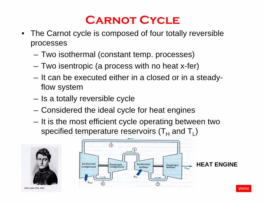
Carnot Cycle• The Carnot cycle is composed of four totally reversible
processes– Two isothermal (constant temp. processes) – Two isentropic (a process with no heat x-fer)– It can be executed either in a closed or in a steady-
flow system– Is a totally reversible cycle– Considered the ideal cycle for heat engines– It is the most efficient cycle operating between two
specified temperature reservoirs (TH and TL)
HEAT ENGINE

WMM
Carnot Cycle

WMM
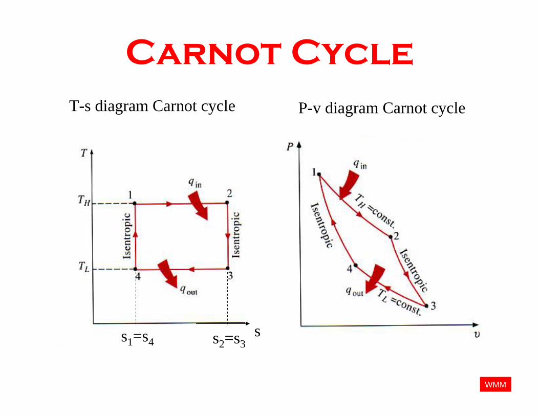
Carnot Cycle• Isothermal Expansion “heat addition”
(1 --- 2) TH = constantQH
• Isentropic Expansion (2 --- 3) TH goes to TL
• Isothermal Compression “Heat rejection”
(3 --- 4) TL = constant
(1) (2)
(2) (3)
(3)(4)
(4)(1)
QL
T
s
qin
qout
(1) (2)
(3)(4)
TH
TL
s1=s4 s2=s3
T-s diagram
• Isentropic Compression (4 --- 1) TL goes to TH

WMM
Carnot Cycle
outinnet
H
Lth
qqWTT
−=
−= 1η
WMM
Carnot Cycle
ss1=s4 s2=s3
T-s diagram Carnot cycle P-v diagram Carnot cycle

WMM
Carnot CycleT
(1) (2)
(3)(4)
ss1=s4 s2=s3
Qout, qout
TL
TH
Wnet = A1-A2= qin -qout
A1 = qin
(1) (2)
Qin, qinQin, qin
A2 = qout
(3)(4)
Qout, qout
¥ All four processes that comprise the Carnot cycle are reversible, and thus the area under each process curve represents the heat transfer for that process.

WMM
Carnot Cycle
ss1=s4 s2=s3
T-s diagram Carnot cycle P-v diagram Carnot cycle
Wnet = qin -qout

WMM
Carnot Cycle
TT
H
LCARNOT
−=1ηCarnot Efficiency Temperatures must be in
Kelvin or Rankine

WMM
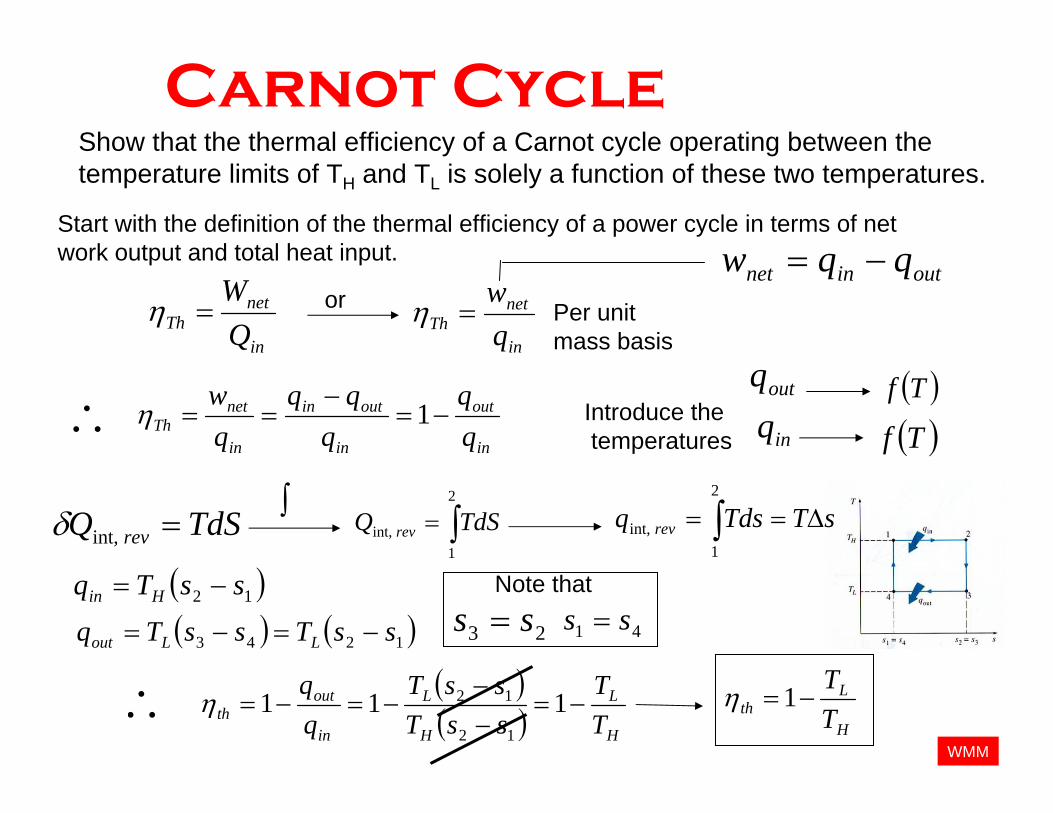
Carnot CycleShow that the thermal efficiency of a Carnot cycle operating between the temperature limits of TH and TL is solely a function of these two temperatures.
TT
H
LCARNOT
−=1η
WMM
Carnot CycleShow that the thermal efficiency of a Carnot cycle operating between the temperature limits of TH and TL is solely a function of these two temperatures.
in
netTh Q
W=η
Start with the definition of the thermal efficiency of a power cycle in terms of net work output and total heat input.
or
in
netTh q
w=η Per unit
mass basis
outinnet qqw −=
Introduce thetemperatures
outq
inq( )Tf
( )Tf
TdSQ rev =int,δ ∫∫=2
1int, TdSQ rev ∫ ∆==
2
1int, sTTdsq rev
∴in
out
in
outin
in
netTh q
qqqw
−=−
== 1η
( )( ) H
L
H
L
in
outth T
TssTssT
−=−−
−=−= 11112
12η∴
( )12 ssTq Hin −=
( ) ( )1243 ssTssTq LLout −=−= 23 ss = 41 ss =Note that
H
Lth T
T−=1η

WMM
Carnot Cycle
¥ Notice that the thermal efficiency of a Carnot cycle is independent of the type of working fluid used (therefore it is good for Ideal and Non-ideal) or that the cycle is executed in a closed (piston-assembly) or steady-flow system(engine or open systems).