carbon capture systems analysis: comparing exergy
TRANSCRIPT

Carbon Capture Systems Analysis: Comparing Exergy Efficiency and Cost of Electricity of Existing and Future Technology Options
(Progress Report 2015) Investigators Chris F. Edwards, Professor, Mechanical Engineering Adam R. Brandt, Assistant Professor, Energy Resources Engineering Adelaide Calbry-Muzyka, Graduate Researcher, Mechanical Engineering Yuchi Sun, Graduate Researcher, Energy Resources Engineering Abstract
Given the likelihood that carbon-based fuels will continue to play a major role in electricity generation, carbon capture and storage (CCS) systems will be a necessary part of solving the climate challenge. With this research project, we aim to develop a framework for quantitative evaluation of existing and proposed carbon-capture technologies. This framework is based on an exergy-based systems analysis performed at the local (system) level and at the global (life cycle) level, and a techno-economic evaluation of the technology.
At the system level, work to date has focused on a few key components. First, the work has focused on building an exergetic analysis of amine-based post-combustion capture systems using the NETL baseline CCS systems as guidance. Second, the work has been focused on completing and documenting the exergetic analysis of the adsorption-based CCS system discussed in prior progress reports.
At the life-cycle level, work to date has focused on two tasks: (1) the development of custom-written Matlab code for exergetic life cycle calculations, using data from the Ecoinvent Data v3 life cycle assessment database; and (2) applying this code to models of two fossil-fuel based power plants from the NETL baseline to demonstrate the functionality of the code. This update presents final results for the application to NETL-compliant amine-based absorption in post-combustion capture from coal-fired systems.
Introduction: Proposed project goals With this research project, we aimed to answer the set of questions: What
technologies or combination of technologies can provide CO2 capture at energy costs much closer to underlying thermodynamic limits? Are the conditions and technology configurations required to achieve such efficiencies possible with available or foreseeable materials? What are the broader (i.e., full system) environmental implications of such technology implementations? What are the likely costs of these technologies? And, given all of the above considerations, which technologies are likely to supply practical, cost-competitive electricity with low life-cycle CO2 emissions?
We proposed to address these questions by examining four types of carbon capture and storage (CCS) systems with different characteristics. Each of the four CCS technologies would be evaluated on three bases: (1) an exergetic systems analysis so that the evaluation takes place with respect to absolute, thermodynamic limits; (2) a full life-

cycle basis such that all ancillary exergy consumption and destruction across the economy—both embodied components and in-process interactions with the environment—are included; and (3) a techno-economic analysis of the technology such that technology options can be evaluated via economic metrics as well. The systems include one baseline option—namely, a MEA-based reference system such as the one studied by NETL [1]—for calibration of methodology, and three advanced technologies. The advanced technologies were chosen in conjunction with GCEP to represent the range of CCS options, and to complement the work of other GCEP research groups. They include one metal-organic framework (MOF) based adsorption system, one biomimetic sorbent, and one ionic liquids absorption system. Our proposed three-part analysis would have resulted in three metrics for each system: work-specific exergy consumption, work-specific carbon emissions to the atmosphere, and first-order estimates of levelized cost of electricity (where the work is the output of the associated power plant, as reduced by the added carbon-capture system). Each of these metrics can be defined on a local (system-only) and global (life cycle) basis. In order to arrive at these metrics, we will be generating exergy distribution plots of each system. These are plots which show the magnitude of exergy destruction in each sub-process in the system, which can both help us understand the inherent inefficiencies in the system and, in the future, to target the most inefficient sub-systems for improvement. The end goal of this project is not only to provide accurate analyses of selected carbon-capture options, but to frame the comparisons of these options in a coherent, compelling way. In the final section of this progress update, we will discuss our overall progress toward addressing all of these proposed goals. Background (re-capitulated from 2014 progress report)
Despite growing concerns about climate change, it is very likely that carbon-based fuels will continue to be used in the coming decades for base-load power generation and for firming of intermittent renewable power sources. Carbon dioxide capture and storage (CCS) is therefore a necessary part of any comprehensive strategy for achieving required reductions in carbon emissions to the atmosphere. Significant studies of proposed carbon capture systems have been performed, including those produced as part of the IPCC process [2], those produced by the U.S. DOE [1], those from the IEA [3], and numerous academic and industrial analyses [4], [5], [6]. These studies arrive at the common conclusion that existing options for post-combustion carbon capture lead to a significant loss of plant output (as much as 30%) and a significant rise in cost of electricity (as much as 80%) when compared to a similar plant without carbon capture.
These numbers might be deemed acceptable—perhaps even unavoidable—were it not for the fact that thermodynamic limits suggest that much more efficient processes are possible. Considered in terms of the minimum work required to separate carbon dioxide generated by combustion of natural gas from its flue gas at atmospheric pressure, only a 2.4% loss of plant output is actually required [7]. Note that even after compressing the CO2 to 100 bar (the pressure prescribed by NETL for use in comparing separation

options, [1]), the fraction of exergy required has only risen to 3.5%. These figures illustrate a key point: Assuming an exergy efficiency of ~50%1 for the overall plant, it should be possible to develop a separation methodology that meets NETL specifications while incurring only a 7% loss of plant output.
This leads to a need to analyze the performance of carbon capture systems via an exergy analysis, in order to compare their operation to this thermodynamic baseline. The objective of this type of analysis is to understand the distribution of exergy within a system such that the causes of its destruction are exposed and quantified. With the exergy distribution of a plant or process known, not only is its overall quality assessed with respect to a fundamental, absolute yardstick, but the locations and magnitudes of losses are revealed for inspection (and thereby improvement). Exergy analysis provides both an unambiguous assessment and immediately points the way to process improvement.
For two reasons, we chose to begin our systems analysis with an adsorption system. The first reason is that two of our advanced carbon capture systems are adsorption-based (the MOF system and the biomimetic sorbent system). The second reason, which became clearer as we advanced in the project, is that very little had been done previously in developing the tools necessary for performing exergy analyses of adsorption-based gas separation systems (whereas absorption-based systems have been studied more extensively). Therefore, our progress on this topic has consisted of two complementary efforts: the development of a generalized and thermodynamically rigorous understanding of the exergy of adsorbed species and mixtures, and the application of this new understanding to an adsorption system model for CO2 capture from flue gas.
Our research takes the analysis beyond the local system level by incorporating global effects in the comparison of carbon capture systems. Using results from the exergetic systems analysis, we are conducting a life-cycle assessment (LCA) in order to better understand how a given CCS technology interacts with the environment at broad scales. This assessment includes not only direct energy consumption (i.e., exergy consumption) at a facility, but also the exergy destruction associated with all “embodied” materials and components, as well as the operational interactions with the environment. The goal of this analysis is to understand which technology option results in the smallest disruption to the environment and results in the smallest drawdown of valuable energy and material resources (e.g., exergy stores) across the entire supply chain. This will enable a better understanding of the tradeoffs between using sophisticated material inputs (which often require more embodied energy inputs) and reducing energy impacts on site.
A number of LCAs have been performed of CCS technologies [8], [9], [10]. These LCAs serve to situate a CCS technology within the broader industrial ecosystem, tracking all material and energy flows both upstream and downstream of a technology of interest. In our case, this set of material and energy flows is utilized in an exergetic approach to LCA [11], [12], [13]. Several professional LCA datasets exist, such as the GaBi databases or the U.S. LCI database. After an overview of the available options, we chose to purchase the Ecoinvent Data life cycle assessment database, commissioned by the
1 For example, the exergy efficiency of a modern (F-class) NGCC power plant is ~52%.
Swiss Centre for Life Cycle Inventories. The selection was based largely on the accessible nature of the raw database files, from which we could construct and manipulate individual matrices and perform exergetic life-cycle assessments without the utilization of a third-party LCA software package.
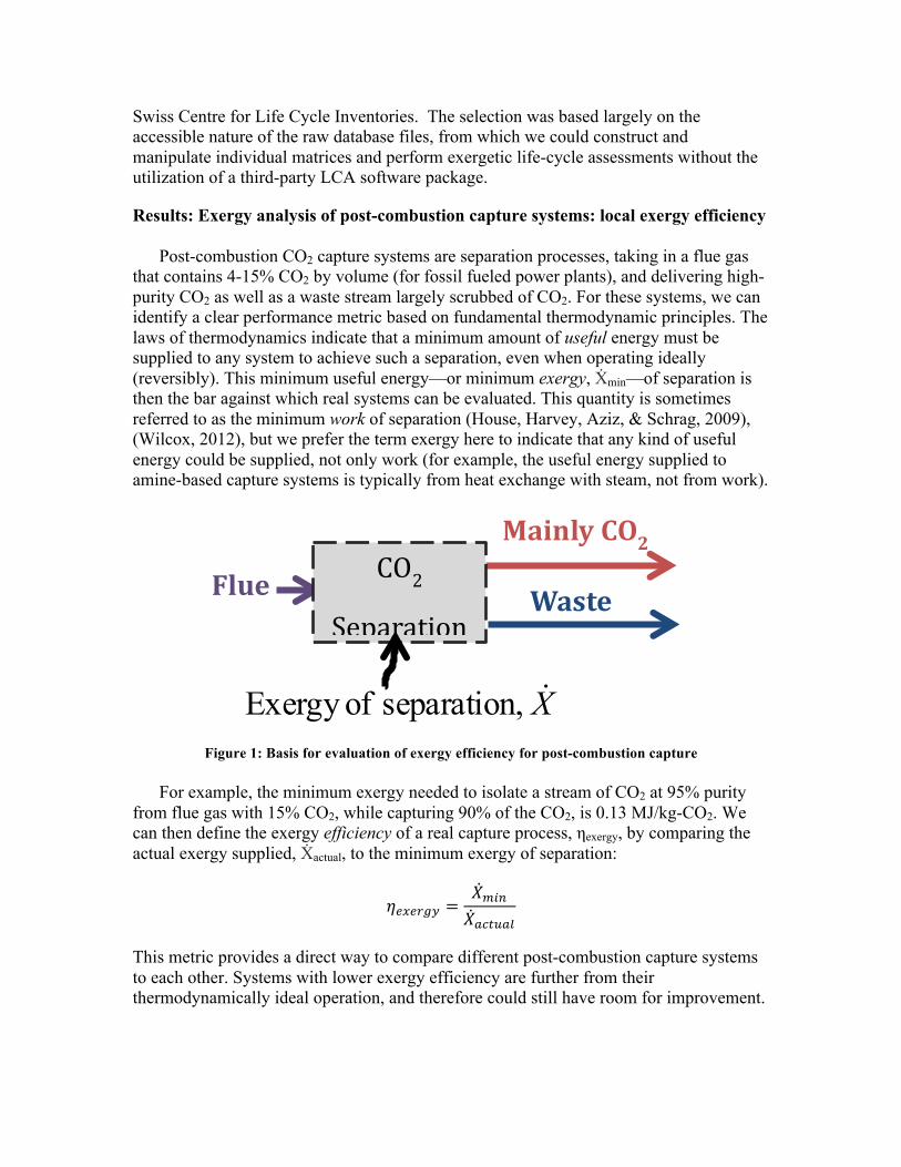
Results: Exergy analysis of post-combustion capture systems: local exergy efficiency Post-combustion CO2 capture systems are separation processes, taking in a flue gas that contains 4-15% CO2 by volume (for fossil fueled power plants), and delivering high-purity CO2 as well as a waste stream largely scrubbed of CO2. For these systems, we can identify a clear performance metric based on fundamental thermodynamic principles. The laws of thermodynamics indicate that a minimum amount of useful energy must be supplied to any system to achieve such a separation, even when operating ideally (reversibly). This minimum useful energy—or minimum exergy, Ẋmin—of separation is then the bar against which real systems can be evaluated. This quantity is sometimes referred to as the minimum work of separation (House, Harvey, Aziz, & Schrag, 2009), (Wilcox, 2012), but we prefer the term exergy here to indicate that any kind of useful energy could be supplied, not only work (for example, the useful energy supplied to amine-based capture systems is typically from heat exchange with steam, not from work).
Figure 1: Basis for evaluation of exergy efficiency for post-combustion capture For example, the minimum exergy needed to isolate a stream of CO2 at 95% purity from flue gas with 15% CO2, while capturing 90% of the CO2, is 0.13 MJ/kg-CO2. We can then define the exergy efficiency of a real capture process, ηexergy, by comparing the actual exergy supplied, Ẋactual, to the minimum exergy of separation:
𝜂!"!#$% =𝑋!"#𝑋!"#$!%
This metric provides a direct way to compare different post-combustion capture systems to each other. Systems with lower exergy efficiency are further from their thermodynamically ideal operation, and therefore could still have room for improvement.
Flue
Mainly CO2
CO2
Separation Waste
X! ,separation ofExergy

Using this metric, we can start by comparing two common proposed post-combustion capture systems: amine absorption, and pressure-swing adsorption. The exergy efficiency for the capture process alone (without compression of the CO2 to pipeline pressures, which is a relatively efficient process) is as follows: 20% for amine absorption systems (based on performance information from (Rochelle, Chen, Freeman, Van Wagener, Xu, & Voice, 2011)), and 22% for pressure-swing adsorption systems (based on (Haghpanah, et al., 2013)).
These numbers on their own already provide noteworthy information about these systems. The fact that they are relatively similar values indicates that, at current levels of understanding and operation of these technologies, amine absorption systems and pressure-swing adsorption systems are effectively equally efficient, on a purely thermodynamic basis, at achieving the desired separation. Note that this does not necessarily indicate that they will both reduce a power plant’s output equally. The reduction in electricity production depends both on how the plant operates (which fuel it uses, its efficiency, whether it is simple- or combined-cycle, etc.), as well as how the plant and the capture system are integrated (whether there are transfers of work, steam, or heat, and where these transfers happen). Instead, exergy efficiency is the absolute, directly-comparable metric for thermodynamic performance of these systems: because both systems are around 20% efficient, both systems could potentially be improved by a factor of up to 5, in terms of the useful energy (or exergy) required to operate them.
On an exergy basis, an efficiency of around 20% is not very high (for example, the exergy efficiency of a modern (F-class) NGCC power plant is ~52%). This leads to the need for a detailed exergy analysis of these systems, in order to identify the system components where the greatest losses occur, and where the greatest gains are therefore possible. The following two sections discuss progress towards completing a detailed exergy analysis for an amine absorption system, and a pressure-swing adsorption system.
In order to perform a detailed exergy analysis of any system, several requirements must be met. The first is the identification of an appropriate system to model. The second is choosing models for system components and fluid properties that result in correct representation of the real system’s behavior. And for exergy analyses, the third requirement is the ability to extract entropy or exergy information from the model: the representation of fluid properties must be done in a way such that the second law of thermodynamics is obeyed and thermodynamic properties are consistent. Although the first two modeling requirements are relatively straightforward, the third has proved non-trivial for the two systems considered.
Exergy analysis of amine absorption system Post-combustion capture of CO2 using absorption by amine solutions is currently the most developed system in use for CO2 capture. In particular, the monoethanolamine (MEA) system included in the DOE/NETL Fossil Fuel Baseline reports (Black, 2010) has been well established as a standard against which future capture technologies should be compared. It is therefore a good choice of system to analyze.

The NETL Baseline reports do not give detailed process information, due to confidentiality concerns regarding some of the proprietary fluids and processes involved. However, the flowrates and states of streams entering and leaving the capture unit are reported, as well as the heat transfer and work required to operate it. Additionally, related studies ( (Kothandaraman, 2010), (White, III, 2002), among others) exist in the literature on similar systems, giving a starting base from which to build a process model. Because of the complexity of the reactions and equilibria involved (between water, CO2, MEA, and their associated ions in solutions), modeling this process is best done in a process modeling software environment, such as AspenPlus. AspenPlus has the stated capability to model these systems, including database information for the relevant chemical reactions species.
A model of the MEA absorption system was therefore built in AspenPlus. The process flow details are shown in Figure 2. The electrolyte non-random two-liquid (e-NRTL) model was used to model excess properties for the mixture. Device efficiencies and operating points were used from the literature where available, or were adjusted to match the capture system’s fluid and energy flows as indicated in the NETL Baseline report. Some of the key parameters to be matched from the NETL report are shown in Table 1, along with the corresponding values from our AspenPlus model, showing good agreement.
Figure 2: Diagram for amine absorption model developed in AspenPlus to approximate the NETL baseline system.
With this model, we have achieved our first two modeling steps: to choose a relevant system to model (the MEA-absorption system from the NETL Baseline report), and to build a model that matched key process conditions.

Table 1: Matching relevant parameters between our AspenPlus model and the NETL Baseline report Value NETL (ref) Aspen (ours) Wtotal 22.4 MW 21.3 MW Qreboil 3.5 MJ/kgCO2 3.5 MJ/kgCO2 yCO2,fin 0.99 0.98
yCO2,stack 0.018 0.016
The final step, to use this model to extract exergy destruction information, is still a work in progress. AspenPlus does not report the exergy of streams; however, it does report entropy of streams, which allows us to calculate the entropy generated in each process component. The exergy destroyed in that component, Xdest, is related to the entropy generation Sgen by the relationship Xdest = T0Sgen.
AspenPlus has many options available in its modeling of thermodynamic and chemical properties, which is its great strength. However, it can easily be its weakness, depending on the modeling choices made. When property models are chosen that are inappropriate for the system at hand, or when the property model chosen is inconsistent with the chosen representation of the chemistry (for example), the results generated by the software may not be correct. This is particularly true of entropy and related properties in systems that include electrolytes. With electrolytes, ensuring consistency involves at least the following: (1) thermodynamic consistency of aqueous phase activity coefficients, (2) agreement of equilibrium constants of the reactions with Gibbs free energy changes of the reactants and products at the correct reference state, and (3) the existence of enthalpy and entropy data (or models thereof) for the reference states of all relevant ions. In practice, if one or more of these conditions are not satisfied, AspenPlus may report apparent entropy values that result in entropy destruction through system components (which would disagree with the second law of thermodynamics). These “apparent” entropy values are therefore incorrect, and should not be used as the basis for an exergy analysis. The final step in this analysis, then, is to reconcile the thermodynamic and chemical modeling assumptions within AspenPlus to enable a correct exergy analysis. This is to be done by referencing published work on the thermodynamic properties of MEA-CO2 mixtures (Hilliard, 2008).
Thank you to summer undergraduate student Christopher Cameron for his assistance in developing the amine model.
Exergy analysis of pressure-swing adsorption systems In our previous update, we noted that three key steps towards completing a detailed exergy analysis of pressure-swing adsorption (PSA) systems for CO2 capture had been completed:
1) Theoretical derivation of the exergy of adsorbed mixtures, to enable exergy balances in process steps with significant accumulation of mixed adsorbed components in a column;

2) Implementation in Matlab of a re-usable set of property methods for quickly accessing all thermodynamic properties of adsorbed mixtures based on known fits to adsorption isotherm data; and
3) The choice of a PSA system to analyze, through collaboration with Reza Haghpanah, who has worked on optimization of these systems (Haghpanah, et al., 2013).
Since then, work has focused primarily on the adaptation of the pressure-swing adsorption Matlab model to enable a detailed exergy analysis. Because exergy analysis depends on identifying a closure term on a balance equation, either entropy generated or exergy destroyed, a high degree of conservation is needed in the conserved quantities of energy and mass. The model inherited as part of this collaboration is a detailed, finite-volume simulation of the adsorption process in a column, with no assumptions of isothermal or isobaric behavior, and allowing for species diffusion. This was well-suited to our need to accurately model the flows through the system. However, because it was originally intended for a different purpose than exergy analysis, did not have as high a level of closure as was needed for our purposes. A significant effort was therefore spent on increasing the degree of mass and energy closure in the model, especially to ensure its robustness to different compositions of inflows over the course of the cycle. Because the original model was developed in conjunction with experimental validation of the system, it was also important to ensure that the model’s generated temperature, pressure, and composition profiles were unchanged while increasing the degree of closure.
Having fulfilled the first two modeling tasks—choosing an appropriate system via collaboration with adsorption experts, and having achieved a model that correctly represented the system behavior—the detailed exergy analysis could be undertaken. The conceptual framework for calculating exergy of adsorbed mixtures had been established, and a set of property methods had been written in Matlab to quickly access thermodynamic properties for analysis (as previously reported). In addition, a thermodynamically consistent mixing rule (the Ideal Adsorbed Solution (Myers & Prausnitz, Thermodynamics of Mixed-Gas Adsorption, 1965)) was implemented in the finite volume model of the column. Performing an exergy analysis of the column initially yielded incorrect results, where two of the four steps in the adsorption cycle showed apparent entropy “destruction”, indicating that thermodynamic inconsistencies may still exist in some of the modeling assumptions taken. A simplified model was built of the adsorption system, which assumed instantaneous equilibration of the gas phase with the surface (adsorbed) phase. This yielded reasonable results: relatively large exergy destruction when pressurizing the column with a gas mixture, and relatively small destruction during the blowdown and evacuation steps. Additional complexity will be introduced to this simple model, in order to identify the source of the thermodynamic inconsistency in the original fully-discretized model and target it.
In addition to this work on system modeling, a publication on the theoretical framework necessary for enabling exergy analysis of adsorption systems was presented at the GHGT-12 conference (International Conference on Greenhouse Gas Control Technologies) in Austin, TX. This reference is listed under “Publications” below.
Results: Exergetic Life-Cycle Analysis The goal of this part of the research is to evaluate amine-based CO2 absorption technology in terms of life cycle exergy destruction, withdrawal, and deposition to the environment. To be more specific, we calculate life cycle exergy flows for a carbon-capture enabled coal-fired power plant. This includes both flows of exergy from and emitted to the natural environment.
To describe the methods applied, we will describe the steps used to construct a process representative of the carbon-capture enabled coal-fired power plant. After which we will review the methodology to calculate life cycle for a certain process. Lastly, we show results for the baseline NETL case.
Methods part 1: Power Plant Models
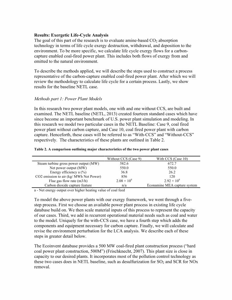
In this research two power plant models, one with and one without CCS, are built and examined. The NETL baseline (NETL, 2013) created fourteen standard cases which have since become an important benchmark of U.S. power plant simulation and modeling. In this research we model two particular cases in the NETL Baseline: Case 9, coal fired power plant without carbon capture, and Case 10, coal fired power plant with carbon capture. Henceforth, these cases will be referred to as “With-CCS” and “Without-CCS” respectively. The characteristics of these plants are outlined in Table 2.
Table 2. A comparison outlining major characteristics of the two power plant cases
Without CCS (Case 9) With CCS (Case 10) Steam turbine gross power output (MW) 582.6 672.7
Net power output (MW) 550.0 550.0 Energy efficiency a (%) 36.8 26.2
CO2 emission to air (kg/ MWh Net Power) 856 120 Flue gas flow rate (m3/h) 2.08 × 10⁶ 2.92 × 10⁶
Carbon dioxide capture feature n/a Econamine MEA capture system a - Net energy output over higher heating value of coal feed
To model the above power plants with our exergy framework, we went through a five-step process. First we choose an available power plant process in existing life cycle database build on. We then scale material inputs of this process to represent the capacity of our cases. Third, we add in recurrent operational material needs such as coal and water to the model. Uniquely for the with-CCS case, we have a fourth step which adds the components and equipment necessary for carbon capture. Finally, we will calculate and revise the environment perturbation for the LCA analysis. We describe each of these steps in greater detail below.
The Ecoinvent database provides a 500 MW coal-fired plant construction process (“hard coal power plant construction, 500M”) (Frischknecht, 2007). This plant size is close in capacity to our desired plants. It incorporates most of the pollution control technology as these two cases does in NETL baseline, such as desulfurization for SO2 and SCR for NOx removal.

As is shown in Error! Reference source not found., without CCS and with CCS scenario have gross turbine power output of 582.6 MW and 672.7 MW respectively, both of which are greater than the 500MW capacity in the base Ecoinvent process. In our default models, we assume that material cost is proportional to plant capacity (i.e., linear scaling). In sensitivity cases explored below, we examine nonlinear scaling of material requirements.
Major operational material needs are added into the model. Their amounts are consistent with NETL baseline. For the carbon capture process, one notable additional consumable is monoethanolamine (MEA). The consumption of these materials for each case can be found in Table 3.
Table 3. Consumables need for without-CCS (NETL case 9) and with-CCS (NETL case 10) case
Reported consumption rate in NETL baseline
Unit Lifetime consumption Unit
Without CCS
With CCS Without CCS
With CCS
Coal 1.98×10⁵ 2.79×10⁵ kg/hr 2.98×10¹⁰ 4.18×10¹⁰ kg Limestone
Sorbent 1.97×10⁴ 2.84×10⁴ kg/hr 2.95×10⁹ 4.26×10⁹ kg
Raw Water 22.3 42.5 m3/min 2.01×10¹¹ 3.83×10¹¹ kg Sodium
Hydroxide 0 7.89 ton/day 0 4.93×10⁷ kg
Sulfuric Acid 0 7.53 ton/day 0 4.71×10⁷ kg Ammonia 78 110 ton 19%
solution/ day
9.26×10⁷ 1.31×10⁸ kg liquid ammonia
MEA solvent 0 1.58 ton/day 0 1.10×10⁷ kg
Building our model of the without-CCS case only requires the previous two sections, scaling and adding in consumables. However, building with-CCS case requires us to model carbon capture equipment.
Modeling the carbon capture system and the material use associated with it is the most complicated part of this modeling effort. In our model, the amine absorption line design follows the schematic provided in NETL baseline as shown in Figure 3.
In the following sections, we will explain the design methods and calculate the material cost of each piece of equipment. For those pieces of equipment that are already included in some form in the Ecoinvent database, namely pumps, compressors and blowers, we will utilize the equipment in the Ecoinvent database with modification. For those pieces of equipment that are not included in Ecoinvent, we model their sizes, capacities, and dimensions to build them from the ground up.

Figure 3. Overall sketch of the Carbon Capture line from NETL baseline with-CCS case, Case 10 (reproduced from NETL (2013, Exhibit 4-1))
The absorbers and strippers in this design are packed bed columns as noted by Fluor (Reddy, 2007). The most important dimensions for these two equipment are diameter, height and thickness. Diameters are designed based on flooding concern. In this research we first calculate a range of diameter that keeps the design gas velocity at 30~80% of the flooding velocity. The framework used here to calculate flooding velocity is proposed by Eckert, et al at 1961. (Eckert, 1961).
Column height is set to ensure a certain pressure drop for a given section area. A pressure drop of 5 kPa, a value widely used in other design and defined in the NETL baseline, is applied to the stripper and absorbers in this study. The pressure loss calculation framework applied to this study is proposed by Stichlmair (1990), which utilized the concept of water hold up. Combined with the range of diameters, we now have a series of diameter/height combination.
Thickness is designed based on structural concerns since these are pressure vessels. The minimum thickness is set to withstand the stress created by internal gas pressure. Lastly, we compare these values to those reported in the literature to determine realistic dimensions for the system.
For blowers, compressors and pumps, the large flowrate exceeds the upper bound of most ready-made models’ intake capacity. Therefore, we have extrapolate their weight from available blowers, compressors and pumps with smaller flow rate. Available data from manufacturers show that compressors and pumps show a generally linear relationship between their weight and their flow capacity. Therefore, we use linear regression between capacity and weight for blower, compressor or pump.
For heat exchanger modeling, shell-and-tube heat exchangers are used in this study. Our analysis is based upon Q, which is heat transferred per unit time in W; U is the overall heat transfer coefficient in W/𝑚!℃; A is heat transfer surface area in 𝑚!, and 𝛥𝑇 is the effective temperature difference in ℃. In this design, we are ultimately looking for A, heat transfer surface area, since it is directly related to equipment size and material use.
When we have the required surface area A, we can solve for the length L and diameter D of the heat exchanger iteratively. The thickness of the tubes are set according to standard dimensions for metal tubes defined by TEMA, Tubular Exchanger Manufacturers Association (1959). With all these dimensions we can calculate the material cost of heat exchangers, and the results for various heat exchangers is shown below.
CCS equipment connected with pipes and ducts. The material cost of them are calculated through their length, diameter and thickness. The length of a pipe or duct is calculated from the distance of the two equipment it connects. The diameter for a pipe or duct is chosen by setting a speed for the fluid within. For liquids, the optimal economic speed could range from 1 to 3m/s in normal operation condition, while it is 10 -25 m/s for gas (Towler, 2013). In our design, the diameters are chosen to make the velocity of the liquid close to 2 m/s, and that of the gas phase close to 20 m/s.
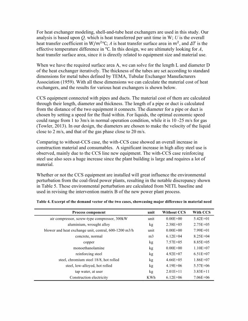
Comparing to without-CCS case, the with-CCS case showed an overall increase in construction material and consumables. A significant increase in high alloy steel use is observed, mainly due to the CCS line new equipment. The with-CCS case reinforcing steel use also sees a huge increase since the plant building is large and requires a lot of material.
Whether or not the CCS equipment are installed will great influence the environmental perturbation from the coal-fired power plants, resulting in the notable discrepancy shown in Table 5. These environmental perturbation are calculated from NETL baseline and used in revising the intervention matrix B of the new power plant process.
Table 4. Excerpt of the demand vector of the two cases, showcasing major difference in material need
Process component unit Without CCS With CCS air compressor, screw-type compressor, 300kW unit 0.00E+00 5.42E+01
aluminium, wrought alloy kg 2.38E+05 2.75E+05 blower and heat exchange unit, central, 600-1200 m3/h unit 0.00E+00 7.99E+01
concrete, normal m3 6.12E+04 8.25E+04 copper kg 7.57E+05 8.85E+05
monoethanolamine kg 0.00E+00 1.10E+07 reinforcing steel kg 4.92E+07 6.51E+07
steel, chromium steel 18/8, hot rolled kg 4.66E+05 1.86E+07 steel, low-alloyed, hot rolled kg 4.19E+06 5.57E+06
tap water, at user kg 2.01E+11 3.83E+11 Construction electricity KWh 6.12E+06 7.06E+06

Table 5. Environmental perturbation for without CCS and with CCS case
Reported emission rate in NETL baseline
Unit Lifetime emission Unit
Without CCS
With CCS Without CCS
With CCS
SO2 0.341 0.008 kg/MWh 2.98E+07 8.07E+05 kg NOx 0.278 0.339 kg/MWh 2.43E+07 3.42E+07 kg
Particulates 0.052 0.063 kg/MWh 4.54E+06 6.36E+06 kg Hg 4.54E-06 5.53E-06 kg/MWh 3.97E+02 5.58E+02 kg
CO2 809 98 kg/MWh 7.07E+10 9.89E+09 kg
Methods Part II: Exergetic Life Cycle Inventory Method
The life cycle inventory method we use in this study utilize two matrices to represent the physical world. The technology matrix A shows the interaction among production processes, in which every column j represents a unique process and each row k represents a unique product. Interactions between the technospere and the ecosphere are captured in a second matrix called the intervention matrix B. The intervention matrix is rectangular in shape, with each column j corresponding to the same process column j in A, and each row i representing a withdrawal from or emission to the environment.
For life cycle assessment, the products in question, in this case the life time of power plant, must be assembled into a column vector 𝑓 (demand vector). 𝑓! is then the amount of product k needed for the construction and operation of our power plant model.
First, in order for the model economy, or technology matrix A, to produce the demand vector 𝑓, it must be multiplied by a scaling vector 𝑠:
𝑓 = 𝐴𝑠 (0.1)
The vector 𝑠 is a unitless vector representing the scaling of each process j to create the requested product 𝑓 with the given A.
Second, the scaling of processes in A directly affects the scale of the interactions those processes have with the environment. Therefore we can define a vector 𝑔, called the inventory vector, which aggregates the interactions in B according to the scaling vector 𝑠.
𝑔 = 𝐵𝑠 = 𝐵𝐴!!𝑓
𝑔 vector contains information on how much environmental perturbation, be it raw material withdrawal, waste flow or energy usage, are incurred from the demand vector 𝑓. Each kind of intervention is associated with some form of exergy change which forms the basis of exergy calculation.

Seven different kinds of exergy are considered in this study: physical exergy, chemical exergy, thermomechanical exergy, potential exergy, kinetic exergy, solar exergy and nuclear exergy. We identify the specific interventions that are related to the exergy above and calculate exergy change. These calculation are well documented in last year’s progress report and therefore omitted here for brevity.
Results
The results of life cycle exergy calculation and further analysis are shown in the following section.
The with-CCS case shows a significant increase in exergy input per unit of electricity output. Global lifetime exergy efficiency, defined as lifetime electricity generation over life cycle exergy drawdown, also declines significantly (see Table 6).
Table 6. Exergy calculation result for Case 9 and Case 10
Unit Without CCS With CCS
Exergy Input MJ 1.288E+12 1.811E+12
Exergy Output MJ 3.921E+10 5.586E+10 Electricity MJ 2.97E+11 2.97E+11
Global exergy Efficiency (Electricity/Exergy Input) % 23.07% 16.40%
Figure 4. Exergy calculation result for “without-CCS” (Case 9) and “with-CCS” Case (Case 10)
02E+114E+116E+118E+111E+12
1.2E+121.4E+121.6E+121.8E+12
2E+12
Case 9 - Exergy Inflow
Case 9 - Exergy Outflow
Case 10 - Exergy Inflow
Case 10 - Exergy Outflow
Exer
gy (M
J)
Exergy Input Exergy Output Electricity

A breakdown on the with-CCS case exergy input shows the causes of the large amount of exergy consumption. As shown in Table 7, the CCS equipment itself only takes up 0.04% of the exergy input. Coal consumption alone makes up the absolute majority of exergy drawdown. It is safe to say that the increase in exergy input between without-CCS and with-CCS cases is mainly caused by the demand of additional energy to fuel the amine reboiler, rather than the extra equipment of the CCS line. The exergy output follow the same pattern (Figure 5), except that the exergy carried over by coal is diverted into other material flow, causing the coal consumption took a smaller fraction of total exergy output.
We can also show the effects on different reference environments. Since the with-CCS case has significantly smaller amount of CO2 emitted, the total exergy it emitted to the atmosphere is smaller than that in without CCS case (see Table 8 and Figure 6). However, the exergy deposition to the water reference environment increases, due to larger cooling requirements and more water pollution due to large material requirements of the with-CCS case.
Table 7. Decomposition of Case 10’s exergy input and output by component
Unit With CCS- Coal Consumption
With CCS - Water Consumption
With CCS - CCS Equipment
With CCS - Power Plant
With CCS Other
Exergy Input MJ 1.792E+12 3.733E+09 3.820E+09 7.383E+08 1.159E+10
Exergy Output MJ 5.214E+10 2.161E+09 5.625E+08 9.590E+07 6.355E+09
Figure 5. Exergy output decomposition by component
85.04%
3.53%0.92%0.16%
10.37%14.96%
Case 10 - Coal Consumption
Case 10 - Water Consumption
Case 10 - power plant
Case 10 - CCS equipment
Case 10 Other

Table 8. Decomposition of exergy by output environment
Unit Without CCS Exergy Output With CCS Exergy Output Air MJ 1.37E+10 1.93E+10 Soil MJ 2.01E+07 2.85E+07
Water MJ 2.55E+10 3.66E+10
Figure 6. Output exergy to different environments (Case 9 = Without CCS, Case 10 =With CCS)
We also performed a sensitivity analysis. This analysis shows that results are not really sensitive to the varying of design of the amine absorption line (see Figure 7). This is because the exergy calculation is in the large part dominated by coal consumption. Among all the variables, the only significant change was due to changing the plant efficiency, which directly influenced the consumption of coal. This holds true for both without-CCS and with-CCS case.
0.00E+00
1.00E+10
2.00E+10
3.00E+10
4.00E+10
5.00E+10
6.00E+10
Air Soil Water
Exer
gy (M
J)
Case 9 Exergy Output Case 10 Exergy Output
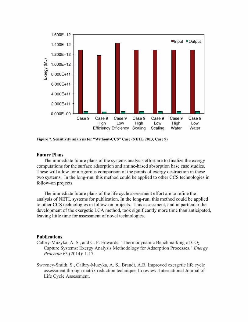
Figure 7. Sensitivity analysis for “Without-CCS” Case (NETL 2013, Case 9)
Future Plans
The immediate future plans of the systems analysis effort are to finalize the exergy computations for the surface adsorption and amine-based absorption base case studies. These will allow for a rigorous comparison of the points of exergy destruction in these two systems. In the long-run, this method could be applied to other CCS technologies in follow-on projects.
The immediate future plans of the life cycle assessment effort are to refine the analysis of NETL systems for publication. In the long-run, this method could be applied to other CCS technologies in follow-on projects. This assessment, and in particular the development of the exergetic LCA method, took significantly more time than anticipated, leaving little time for assessment of novel technologies.
Publications Calbry-Muzyka, A. S., and C. F. Edwards. "Thermodynamic Benchmarking of CO2
Capture Systems: Exergy Analysis Methodology for Adsorption Processes." Energy Procedia 63 (2014): 1-17.
Sweeney-Smith, S., Calbry-Muzyka, A. S., Brandt, A.R. Improved exergetic life cycle
assessment through matrix reduction technique. In review: International Journal of Life Cycle Assessment.
0.000E+00
2.000E+11
4.000E+11
6.000E+11
8.000E+11
1.000E+12
1.200E+12
1.400E+12
1.600E+12
Case 9 Case 9 High
Efficiency
Case 9 Low
Efficiency
Case 9 High
Scaling
Case 9 Low
Scaling
Case 9 High
Water
Case 9 Low
Water
Exer
gy (M
J)Input Output

Bibliography
Black, J. (2010). Cost and Performance Baseline for Fossil Energy Plants: Volume 1 - Bituminous Coal and Natural Gas to Electricity (Revision 2). Pittsburgh, PA: National Energy Technology Laboratory (NETL). Bosch, M. et al. (2007). Applying cumulative exergy demand (CExD) indicators to the Ecoinvent database. The International Journal of Life Cycle Assessment , 12 (3), 181-190. Davison, J. (2007). Performance and costs of power plants with capture and storage of CO2. Energy , 32 (7), 1163-1176. Dewulf, J. et al. (2007). Cumulative Exergy Extraction from the Natural Environment (CEENE): a comprehensive Life Cycle Impact Assessment method for resource accounting. Environmental Science & Technology , 41 (24), 8477-8483. Eckert, John S. "Design techniques for sizing packed towers." Chemical Engineering Program 57 (1961): 54.
Edwards, C. F. (2012). Exergy Revisited. In Course Notes for ME370B. Stanford, CA: Stanford University, Department of Mechanical Engineering. Finnveden, G., & Östlund, P. (1997). Exergies of natural resources in life-cycle assessment and other applications. Energy , 22 (9), 923-931. Green, Don W. "Perry’s chemical engineers’ handbook." McGraw-Hill (2008): 16-11.
Frischknecht, R., Jungbluth, N., Althaus, H. J., Hischier, R., Doka, G., Bauer, C., ... & Loerincik, Y. (2007). Implementation of life cycle impact assessment methods. Data v2. 0 (2007). Ecoinvent report No. 3. Ecoinvent Centre, Swiss Federal Laboratories for Materials Testing and Research (EMPA), Duebendorf (Switzerland).
Haghpanah, R. et al., (2013). Multiobjective optimization of a four-step adsorption process for postcombustion CO2 capture via finite volume simulation. Industrial & Engineering Chemistry Research , 52, 4249-4265. Haghpanah, R. et al. (2013). Multiobjective optimization of a four-step adsorption process for postcombustion CO2 capture via finite volume simulation. Industrial & Engineering Chemistry Research , 52, 4249-4265. Hermann, W. (2005). An assessment of carbon capture technology and research opportunities. Stanford, CA: Global Climate & Energy Project.

Herzog, H., Meldon, J., & Hatton, A. (2009). Advanced post-combustion CO2 capture. Clean Air Task Force . Hilliard, M. D. (2008). A Predictive Thermodynamic Model for an Aqueous Blend of Potassium Carbonate, Piperazine, and Monoethanolamine for Carbon Dioxide Capture from Flue Gas. Austin, TX: UT Austin PhD Thesis. House, K. Z., Harvey, C. F., Aziz, M. J., & Schrag, D. P. (2009). The energy penalty of post-combustion CO2 capture & storage and its implications for retrofitting the U.S. installed base. Energy & Environmental Science , 2, 193-205. IPCC. (2005). Special Report on Carbon Dioxide Capture and Storage. Cambridge, UK: Cambridge University Press. Kearns, D. T., & Webley, P. A. (2004). Application of an adsorption non-flow exergy function to an exergy analysis of a pressure swing adsorption cycle. Chemical Engineering Science , 59 (17), 3537-3557. Koornneef, J., & al., e. (2008). Life cycle assessment of a pulverized coal power plant with post-combustion capture, transport, and storage of CO2. International Journal of Greenhouse Gas Control , 2 (4), 448-467. Kothandaraman, A. (2010). Carbon Dioxide Capture by Chemical Absorption: A Solvent Comparison Study. Cambridge, MA: MIT PhD Thesis. Myers, A. L. (2002). Thermodynamics of adsorption in porous materials. AIChE Journal , 48 (1), 145-160. Myers, A. L., & Prausnitz, J. M. (1965). Thermodynamics of mixed-gas adsorption. AIChE Journal , 11 (1), 121-127. Odeh, N. A., & Cockerill, T. T. (2008). Life cycle GHG assessment of fossil fuel power plants with carbon capture and storage. Energy Policy , 36 (1), 367-380. Pehnt, M., & Henkel, J. (2009). Life cycle assessment of carbon dioxide capture and storage from lignite power plants. International Journal of Greenhouse Gas Control , 3 (1), 49-66. Reddy, S. (2008, May). Econamine FG Plus SM Technology for Post-combustion CO2 Capture. In 11 th Meeting of the International Post-Combustion CO2 Capture Network.
Rochelle, G., Chen, E., Freeman, S., Van Wagener, D., Xu, Q., & Voice, A. (2011). Aqueous piperazine as the new standard for CO2 capture technology. Chemical Engineering Journal , 171 (3), 725-733. Rubin, E. S., Chen, C., & Rao, A. B. (2007). Cost and performance of fossil fuel power plants with CO2 capture and storage. Energy Policy , 35 (9), 4444-4454.

Ruthven, D. M. (1984). Principles of Adsorption and Adsorption Processes. New York: John Wiley and Sons. Siperstein, F. R., & Myers, A. L. (2001). Mixed-gas adsorption. AIChE , 47 (5), 1141-1159. Stichlmair, J., Bravo, J. L., & Fair, J. R. (1989). General model for prediction of pressure drop and capacity of countercurrent gas/liquid packed columns. Gas Separation & Purification, 3(1), 19-28.
Towler, Gavin P., and Ray K. Sinnott. Chemical engineering design: principles, practice, and economics of plant and process design. Elsevier, 2013.
Tubular Exchanger Manufacturers Association. (1959). Standards of Tubular Exchanger Manufacturers Association. TEMA.
Valenzuela, D. P., & Myers, A. L. (1989). Adsorption Equilibrium Data Handbook. Prentice Hall. White, III, C. W. (2002). Aspen Plus Simulation of CO2 Recovery Process. Pittsburgh, PA: DOE/NETL. Wilcox, J. (2012). Carbon Capture. New York: Springer.
Contacts Chris F. Edwards: [email protected] Adam R. Brandt: [email protected] Adelaide Calbry-Muzyka: [email protected] Yuchi Sun: [email protected]