carbides in high chromium cast...
TRANSCRIPT
Carbides in High Chromium Cast Irons
A. Wiengmoon
Department of Physics, Faculty of Science, Naresuan University, Phitsanulok 65000, E-mail: [email protected]
Abstract – High chromium cast irons are widely
used as abrasion resistant materials. The mechanical
properties and wear resistance of these irons depend
on the type, hardness, morphology, distribution,
volume fraction and orientation of the eutectic and
precipitated carbides within their microstructures and
on the nature of the matrix supporting these hard
eutectic carbides. This paper is aimed to review the
nature and crystallography of eutectic carbides and
secondary carbides which are formed during
solidification and precipitated during heat treatments
of high chromium irons.
Keywords – High chromium cast iron, Eutectic carbide, Secondary carbide, Microstructure.
1. INTRODUCTION
High chromium irons can bridge the gap between the low toughness/good abrasion resistance Ni-Hard irons and the higher toughness/lower abrasion resistance high manganese steels. The abrasion resistance of high chromium irons is 20-25 times better than low carbon steels when the abrasive particles, such as quartz and garnet particles, are softer than the carbides [1]. Nearly all high chromium cast irons used for abrasion resistance are hypoeutectic alloys containing 10-30 wt%Cr and 2-3.5 wt%C. The alloys containing 12 wt%Cr are the cheapest, but 18-22 wt%Cr irons are the most popular range for general abrasion resistance such as rollers and tables in coal pulverizing or as liners in dry ball mills. The alloys containing 27-30 wt%Cr and 2.0-2.7 wt%C have been specially developed for combined abrasion and corrosion resistance in wet wear applications, for example slurry pumping in extraction processes [2-4]. Irons with 30-35 wt%Cr are used to resist oxidation and corrosion at high temperatures in applications such as furnace and burner parts. Microstructures of these alloys consist of ferrite and eutectic carbides [5-8]. The hypoeutectic high Cr irons solidify as primary austenite dendrites with a network of interdendritic eutectic carbides and during cooling some of the eutectic austenite around the eutectic carbides transforms to martensite [4, 5, 9-11]. The hardness levels of the austenitic irons are 500-520 HV. In some applications, as-cast austenitic irons can be used without heat treatment since the austenite can work harden at wear surfaces to provide a self-replacing wear resistant surface structure
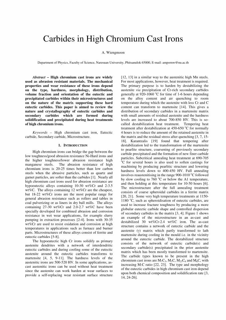
[12, 13] in a similar way to the austenitic high Mn steels. For most applications, however, heat treatment is required. The primary purpose is to harden by destabilizing the austenite via precipitation of Cr-rich secondary carbides generally at 920-1060 oC for time of 1-6 hours depending on the alloy content and air quenching to room temperature during which the austenite with less Cr and C content can transform to martensite [14]. This gives a distribution of secondary carbides in a martensite matrix with small amounts of residual austenite and the hardness levels are increased to about 700-850 HV. This is so-called destabilization heat treatment. Tempering heat treatment after destabilization at 450-650 oC for normally 4 hours is to reduce the amount of the retained austenite in the matrix and the residual stress after quenching [3, 7, 15-18]. Karantzalis [19] found that tempering after destabilization led to the transformation of the martensite to pearlite structure, coarsening of previously secondary carbide precipitated and the formation of new finer carbide particles. Subcritical annealing heat treatment at 690-705 oC for several hours is also used to soften castings for machining by producing pearlitic structure and lowering hardness levels down to 400-450 HV. Full annealing involves reaustenitising in the range 900-1010 oC followed by slow cooling to 760 oC or below the A1 temperature, and then holding at this temperature for 10-50 hours [6]. The microstructure after the full annealing treatment consists of coarse spheroidal carbides in a ferrite matrix [20, 21]. Some very high temperature treatments at 1150-1180 oC, such as spheroidisation of eutectic carbides, are used to increase fracture toughness by producing a more globular eutectic carbide shape and controlled dispersion of secondary carbides in the matrix [3, 4]. Figure 1 shows an example of the microstructure in an as-cast and destabilized 30 wt%Cr-2.4 wt%C iron. The as-cast structure contains a network of eutectic carbide and the austenite (γ) matrix which partly transformed to lath martensite during cooling in the mould i.e. in the vicinity around the eutectic carbide. The destabilized structure consists of the network of eutectic carbide(s) and secondary carbide(s) precipitated in the prior austenite matrix which has been mostly transformed to martensite. The carbide types known to be present in the high chromium cast irons are M7C3, M3C, M23C6 and M6C, with increasing M:C ratio [22, 23]. The type and morphology of the eutectic carbides in high chromium cast iron depend upon both chemical composition and solidification rate [3, 14, 24-26].
Inoue and Masumoto [29] found an orientation relationship between the M3C and the M7C3 carbides in high carbon-chromium steels as;
373)0001(//)110( CMCM
373)0011(//)012( CMCM
373)0211(//)001( CMCM
Wang [30] found an orientation relationship between the M3C and the ferrite matrix in 15 wt%Cr-1 wt%Mo-1.5 wt%V high chromium cast iron as;
ferriteCM )100(//)010(3
, ferriteCM ]011[//]001[
3
Figure 1 (a) micro-structure of as-cast 30 wt%Cr-2.4 wt%C with
austenitic matrix, partially transformed to martensite (b)microstructure of destabilized 30 wt%Cr-2.4 wt%C containing
secondary carbides with martensitic matrix [3].
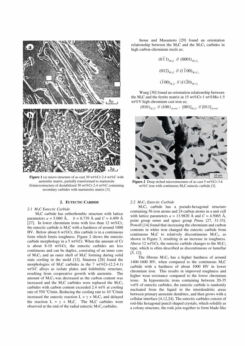
Figure 2 Deep etched microstructures of as-cast 5 wt%Cr-3.6
wt%C iron with continuous M3C eutectic carbide [3].
2. EUTECTIC CARBIDE
2.1 M3C Eutectic Carbide
M3C carbide has orthorhombic structure with lattice parameters a = 5.060 Å, b = 6.739 Å and C = 4.499 Å [27]. In lower chromium irons with less than 12 wt%Cr, the eutectic carbide is M3C with a hardness of around 1000 HV. Below about 6 wt%Cr, this carbide is in a continuous form which limits toughness. Figure 2 shows the eutectic carbide morphology in a 5 wt%Cr. When the amount of Cr is about 8-10 wt%Cr, the eutectic carbides are less continuous and can be duplex, consisting of an inner core of M7C3 and an outer shell of M3C forming during solid state cooling in the mold [12]. Sinatora [28] found the morphologies of M3C carbides in the 7 wt%Cr-(2.2-4.1) wt%C alloys as isolate plates and ledebulitic structure, resulting from cooperative growth with austenite. The amount of M7C3 was decreased as the carbon content was increased and the M3C carbides were replaced the M7C3 carbides with carbon content exceeded 2.4 wt% at cooling rate of 550 oC/min. Reducing the cooling rate to 10 oC/min increased the eutectic reaction L = γ + M7C3 and delayed the reaction L = γ + M3C. The M3C carbides were observed at the end of the radial eutectic M7C3 carbides.
2.2 M7C3 Eutectic Carbide
M7C3 carbide has a pseudo-hexagonal structure containing 56 iron atoms and 24 carbon atoms in a unit cell with lattice parameters a = 13.9820 Å and C = 4.5065 Å, point group mmm and space group Pmna [27, 31-33]. Powell [14] found that increasing the chromium and carbon contents in white iron changed the eutectic carbide from continuous M3C to relatively discontinuous M7C3, as shown in Figure 3, resulting in an increase in toughness. Above 12 wt%Cr, the eutectic carbide changes to the M7C3 type, which is often described as discontinuous or lamellar [5, 12]. The fibrous M7C3 has a higher hardness of around 1400-1600 HV, when compared to the continuous M3C carbide with a hardness of about 1000 HV in lower chromium iron. This results in improved toughness and higher wear resistance compared to the lower chromium irons. In hypoeutectic irons containing between 20-35 vol% of eutectic carbides, the eutectic carbide is randomly nucleated from the liquid in the interdendritic areas between primary austenite dendrites, and then grows with a cellular interface [4,12,24]. The eutectic carbides consist of rod-like hexagonal pencil shaped crystals, which solidify as a colony structure, the rods join together to form blade-like
a
b
γγγγ
γγγγ
10 um
a

structures which are often described as lamellar. Cross sections of fine eutectic carbides are sometimes incorrectly described as globular. The rod-like M7C3 carbides become finer with increasing chromium content and with increasing rate of eutectic solidification [24-26]. The eutectic colony size is also decreased and the carbide spacing is also reduced with increasing the rate of eutectic solidification and with increase in chromium content. The length of eutectic cells becomes larger with an increase in the eutectic freezing range. The colony diameter in 15 wt%Cr and 30 wt%Cr irons was found to be 585 µm and 310 µm, respectively [24, 25].
Figure 3 Deep etched microstructures of as-cast 30 wt%Cr-2.4
wt%C iron with finer and discontinuous M7C3 eutectic carbide [2].
Durman and Elwell [34] suggested that, in hypoeutectic alloys, the eutectic carbides form an interconnected network while, in hypereutectic material, the primary M7C3 exists as individual rods. Pearce [5] found that the eutectic M7C3 carbides grew as hexagonal rods or blades and that the overall diameter of the rods ranged from 1 to 4 µm with the smallest diameters of crystals within a cluster being in the order of 0.5 µm. There is only one growth direction, the <0001> [14]. Wiengmoon [35] found that the eutectic M7C3 carbide in as-cast semi-solid processed 27 wt%Cr cast iron consists of radiating clusters mixed with directional clusters. The size of these radiating eutectic colonies, measured from edge to edge was about 15 µm. In comparison, the thickness and the spacing of the eutectic carbide blades in as-cast conventionally cast 27 wt%Cr cast iron were about 0.6 µm and 0.25 µm, respectively, which were less than the values measured in the as-cast semi-solid processed 27 wt%Cr cast iron, i.e. about 0.9 µm and 0.4 µm, respectively. Eutectic M7C3 tends to grow as hollow rods with the diameter of the hollow core between 0.2 and 0.6 µm. This core is filled with matrix material of the same composition as that adjacent to the carbides. The cores can vary from circular to various other shapes and can move to the edge of the eutectic M7C3 during growth [5, 14]. Thin foil TEM studies [5, 35-38] of the eutectic carbides in 15-30 wt%Cr irons have confirmed that these carbides are M7C3 and that they are formed as rod- and/or blade-like structures. As mentioned above the eutectic M7C3 grows as hollow pencil
like crystals of hexagonal cross section, the blades being polycrystalline aggregates of rods as shown in Figure 4. M7C3 forms as eutectic carbide (or as primary carbides during solidification, or secondary carbides described later)) with a distinguishable characteristic that it always appears to contain a high concentration of structural faulting. Stacking sequence faults likely occur on { 0110 } and { 0211 } planes giving rise to characteristic elongated reflections (streaking) in electron diffraction patterns and probably the presence of anti-phase domain boundaries in crystals [5, 36, 38-40]. Carpenter [36] reported that stacking faults within (Fe,Cr)7C3 carbide occur by the omission of carbon atoms from the unit cell and as such do not destroy the hexagonal symmetry of the carbide.
Figure 4 (a) Blade-like (1) and radiating clusters (2)
morphologies of the eutectic carbide in the as-cast 27 wt%Cr cast iron, (b) BF-TEM micrograph shows the encapsulated core of the
prior austenite within the M7C3 eutectic carbide in the as-cast semi-solid processed 27 wt%Cr cast iron [35].
In hypereutectic irons with volume fraction of carbides over 35 vol%, the eutectic hexagonal M7C3
1
2
a
b
10 um
b

carbides solidifies around the primary carbide as colonies [12, 24]. Shtansky [32] found the orientation relationships between the M7C3 carbide and the ferrite (bcc) as;
37)1001(//)131( CMferrite 37
)0211(//)131( CMferrite
37)0211(//)152( CMferrite or 37
)0011(//)152( CMferrite
37)0001(//)113( CMferrite ≈
37)0001(//)113( CMferrite ≈
The M7C3 contains 24-50 %Cr content and 8.6-8.9 %C content with the Gibbs free energy of formation -10 to -20 kJ/mole [7]. Pearce [2] reported that the microprobe analysis of the eutectic carbide in the as-cast 30 wt%Cr-2.4 wt%C iron suggests a formula of (Fe1.8Cr5.4)C3 for eutectic M7C3. This result is in agreement with Dyson and Andrews [40] who studied the carbides in alloy steel containing 3.8 wt%Cr-0.14 wt%C-0.3 wt%Mo by x-ray fluorescence analysis, finding that the carbide formula is (Fe1.4Cr5.6)C3, the average M : C ratio is 2.36 : 1 and the average percentage of carbon is 8.63 wt%. Dogan [41] found that the formula of eutectic carbide in the 25 wt%Cr-3 wt%C iron determined by wavelength dispersive spectroscopy was (Fe2.2Cr4.8)C3. Wiengmoon [38] reported that the formula of eutectic carbide in the as-cast 30 wt%Cr-2.3 wt%C iron by microprobe analysis and electron energy loss spectroscopy is (Fe1.8Cr5.9)C3 and (Fe1.3Cr6.3)C3, respectively. The chemical analysis of eutectic carbide in the TEM thin foil of the as-cast 26.6 wt%Cr-2.7 wt%C iron was studied by Carpenter [42]. It was found that the chemical formula at the centre part of the eutectic carbide is Fe2Cr5C3, whilst that at the edge is (Fe2.2Cr4.8)C3. Pearce and Elwell [43] reported the Cr : Fe ratios of the 30 wt%Cr-2.44 wt%C iron by energy dispersive analysis which varied from 2.29-2.77 for the M7C3.
2.3 M7C3 – M23C6 Duplex Eutectic Carbides
During conventional destabilization or annealing treatments, the eutectic M7C3 carbides in 10-25 wt%Cr irons do not appear to undergo any structural change, however, in the 30 wt%Cr irons, a transition from M7C3 to M23C6 has been observed in the eutectic carbides [11, 44]. This results in duplex eutectic carbide structures consisting of cores of M7C3 surrounded by shells of M23C6. TEM investigation is needed to reveal full details of this duplex structure and to study the mechanism by which the transformation takes place. Figure 5 reveals M23C6 shells surrounding the remaining cores of eutectic M7C3 with faulting contrast. The extent of the transformation depends on destabilization temperatures and times [37]. This transformation has only been observed within the very high chromium content irons, probably because M23C6 carbide is stable only at the high chromium content [45]. The M23C6 is believed to nucleate at the original interface between the eutectic M7C3 and the matrix; it then grows gaining metal atoms from the matrix and consuming the M7C3 [37]. The behavior of alloys containing 26 wt%Cr and 30wt%Cr have been compared by Pearce [45]. It was found that, as expected, the hardness of the irons were increased after hardening heat treatment. However, the
heat-treated 26 wt%Cr iron gave 36% increase in dry wear resistance, whereas the heat-treated 30 wt%Cr iron gave only 4% increase in dry wear resistance. In wet wear conditions, it has been reported [7] that the as-cast 30 wt%Cr iron was better than the as-cast or heat-treated 25 wt%Cr irons, however, the heat-treated 30 wt%Cr iron performed surprisingly worse. It was believed [45, 46] that the lack of improvement in both dry and wet wear resistance of the 30 wt%Cr irons after destabilization and hardening-tempering treatments was due to the eutectic M7C3→M23C6 transformation forming the duplex eutectic carbides. These duplex carbides appear to have a greater tendency to crack and become detached during wear than single M7C3 carbide [45]. The corrosive wear resistance of hardened 30 wt%Cr irons appears to be inferior to that of the as-cast material, while the opposite is true for 25 wt%Cr iron where there is no evidence of a M7C3→M23C6 transition in the eutectic carbides during heat treatment [47, 48]. Pearce and Elwell [43] reported the Cr : Fe ratios of the 30 wt%Cr-2.44 wt%C iron by energy dispersive analysis which varied from from 1.61-1.68 for the M23C6 shell. Inoue [29] found the orientation relationships between the M7C3 carbide and the M23C6 as;
3723)0001(//)121(
6 CMCM
3723)0011(//)111(
6 CMCM
3723)0211(//)110(
6 CMCM
Figure 5 BF-TEM shows a duplex core-shell structure of the eutectic carbides after destabilization in 30 wt%Cr -2.3 wt%C
[38].
3. SECONDARY CARBIDE
As mentioned earlier, the austenite matrix of high chromium iron can be destabilized by heat treatment in which the C and Cr contents of this matrix become reduced as a result of the precipitation of secondary carbides. This raises the martensite-start temperature (Ms) of the austenite so that after destabilization and air hardening, the microstructure consists of secondary carbides in a matrix of martensite and some retained austenite. It has been reported that secondary carbides formed during the
M23C6
M7C3 αααα′′′′
destabilization of Cr irons do not nucleate and grow on the eutectic carbides, but precipitated within the dendritic matrix [4, 5, 11, 44]. However, an argument has also been raised [35] that the M23C6 can nucleate on the M7C3 eutectic carbide. The precipitation occurs on preferred planes in the regions of the austenite matrix remote from the eutectic carbides [49]. Normally, it is believed that secondary carbides precipitate on slip bands or in subgrain boundaries within the austenite regions [4, 49]. Slip bands or subgrain boundaries occur due to stress, which is produced by the difference in thermal expansion between the eutectic carbides and the matrix [34]. The type of secondary carbides depends on the alloy composition and destabilization temperature.
3.1 M3C Secondary Carbide
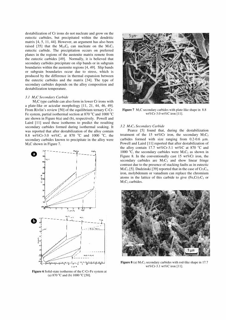
M3C type carbide can also form in lower Cr irons with a plate-like or acicular morphology [11, 21, 44, 46, 49]. From Rivlin’s review [50] of the equilibrium ternary C-Cr-Fe system, partial isothermal section at 870 oC and 1000 oC are shown in Figure 6(a) and (b), respectively. Powell and Laird [11] used these isotherms to predict the resulting secondary carbides formed during isothermal soaking. It was reported that after destabilization of the alloy contain 8.8 wt%Cr-3.0 wt%C, at 870 oC and 1000 oC, the secondary carbides known to precipitate in the alloy were M3C shown in Figure 7.
Figure 6 Solid-state isotherms of the C-Cr-Fe system at
(a) 870 oC and (b) 1000 oC [50].
Figure 7 M3C secondary carbides with plate-like shape in 8.8
wt%Cr-3.0 wt%C iron [11].
3.2 M7C3 Secondary Carbide
Pearce [5] found that, during the destabilization treatment of the 15 wt%Cr iron, the secondary M7C3 carbides formed with size ranging from 0.2-0.6 µm. Powell and Laird [11] reported that after destabilization of the alloy contain 17.7 wt%Cr-3.1 wt%C at 870 oC and 1000 oC, the secondary carbides were M7C3 as shown in Figure 8. In the conventionally cast 15 wt%Cr iron, the secondary carbides are M7C3 and show linear fringe contrast due to the presence of stacking faults as in eutectic M7C3 [5]. Dudzinski [39] reported that in the case of Cr7C3, iron, molybdenum or vanadium can replace the chromium atoms in the lattice of this carbide to give (Fe,Cr)7C3 or M7C3 carbides.
Figure 8 (a) M7C3 secondary carbides with rod-like shape in 17.7
wt%Cr-3.1 wt%C iron [11].
a
b

3.3 M23C6 Secondary Carbides
M23C6 carbide crystals are face-centered cubic, in which 92 metal atoms located at the 4(a), 8(c), 32(f) and 48(h) symmetry sites of space group Fm3m and with lattice parameter a = 10.6214 Å [31, 51]. The M23C6 contains Cr contents with a lower limit of around 60 wt% and a C content of 5.3-5.7 wt%. The Gibbs free energy of the formation is -8 to -15 kJ/mole [7]. In the alloys with high chromium content above 25-30 wt%, M23C6 type carbides are formed as fine interconnected rods (fibrous shape). It was reported that after destabilization of the alloy contain 29.3 wt%Cr-2.5 wt%C at 870 oC and 1000 oC, the secondary carbides were M23C6 as shown in Figure 9. TEM results confirmed the type of secondary carbides in conventionally cast 30 wt%Cr iron as M23C6 [2, 37, 38], which has a cubic lattice and does not contain faults. In conventionally cast irons, SEM and TEM observations have shown that secondary carbides, either M7C3 or M23C6, do not nucleate on M7C3 eutectic carbide, but form separately within the matrix and grow at sub-boundaries in the matrix and/or along habit directions to develop fibrous networks [5, 11, 38]. However, M23C6 secondary carbide in semi-solid cast 27 wt%Cr iron [35] was found to nucleate also on M7C3 eutectic carbide. In conventionally cast 18-20 wt%Cr irons, it has been shown that, as well as M7C3 secondary carbide, M23C6 carbides can also form and grow along {111} planes in the original austenite matrix [21]. In conventionally cast 27 wt%Cr irons, both M7C3 and M23C6 cubic carbides can also found [8]. Various studies have revealed that the sizes of secondary carbides vary from 0.2-0.6 µm with both size and distribution being influenced by prior annealing and destabilization conditions, and by the segregation patterns in the original dendritic and eutectic austenite formed on solidification.
Figure 9 M23C6 secondary carbides with fibrous shape in 29.3 wt%Cr-2.5 wt%C iron [11].
3.4 M6C Secondary Carbide
In conventionally cast 18-20 wt%Cr irons, M6C secondary carbides can form together with M23C6 and M7C3 [21]. M6C carbide crystal is FCC with lattice parameters a = 11.0823 Å, point group m3m and space group Fd3m [31, 33]. Kibble [52] found that both M6C and M7C3 secondary carbides were precipitated in 19 wt%Cr iron after annealing at 800 oC and followed by destabilization at 1000 oC. Inoue [29] found the transformation of M23C6 carbide to M6C carbide in 4 wt%C-18 wt%Cr with 8 wt%W or 8 wt%Mo steels during tempering at 700 oC for longer time than about 1 hour. The orientation relationships among M23C6 to M6C were;
CMCM 623)011(//)101(
6
CMCM 623)111(//)111(
6
CMCM 623)112(//)112(
6
4. EFFECTS OF ADDITIONAL ALLOYING ELEMENTS
Irons which are required to be predominantly austenitic but which have insufficient as-cast hardenability to avoid pearlite formation are described as under-alloyed. To prevent this, the correct level of austenite-stabilising elements must be added [12]. For heat treated irons, since chromium is present in both the eutectic and secondary carbides, only part of the total Cr content of the iron is retained in the matrix to increase hardenability and supplementary addition of Mo, Ni, Cu and Mn are needed if heavier sections are to be fully hardened [2, 4, 7].
The effects of additional alloying elements in Cr irons have been extensively studied [53-57]. Normally, alloying additions such as molybdenum, manganese, nickel and copper are used to increase hardenability and to prevent pearlite formation in the thicker sections of castings. Irons alloyed with carbide-forming elements such as molybdenum, vanadium and tungsten have been developed for special applications such as hot working mill rolls in the steel industry [4, 13]. Overalloying must be avoided since too high content of alloying element increases both the time for destabilization process and the levels of retained austenite in the structure, the latter resulting in lower abrasion resistance. Under-alloying is equally as damaging since too low a content of alloying element encourages pearlite formation in both as cast irons and after hardening [12].
5. CONCLUSIONS
Wear resistance and mechanical properties of high chromium cast irons depend on the eutectic and precipitated carbides within their microstructures and on the nature of the matrix supporting the hard eutectic carbides. Table 2 gives a conclusion of the types, crystallography, morphologies, and hardness of carbides in high chromium cast irons, and comparison of the hardness of some abrasive materials in Table 3 [4, 7].

Table 2 Types, crystallography, morphologies, and hardness of carbides in high chromium cast irons.
Carbide,
abrasive
materials
Crystal structure Morphology Hardness
(HV)
M3C - Orthorhombic - Lattice parameters
a = 5.060 Å, b = 6.739 Å, c = 4.499 Å
Continuous plate
800-1100
M6C - FCC - Lattice parameters
a = 11.0823 Å - Point group m3m - Space group Fd3m
Facet and single rod
1200-1800
M7C3 - Hexagonal - Lattice parameters
a = 13.982 Å, c = 4.506 Å
- Point group mmm - Space group Pmna
Hexagonal rod and blade-like
1000-1800
M23C6 - FCC - Lattice parameter
a = 10.6214 Å - Point group m3m - Space group Fm3m
Irregular shapes, rod, needle, plates, cubic
1000
Table 3 Hardness of some abrasive materials.
Abrasive materials Hardness (HV)
SiC 2600 VC 2000-3000 Al2O3 1800 silica 1430
high carbon martensite 500-1010
6. ACKNOWLEDGMENT
I would like to express my extremely appreciation to Assoc. Prof. Dr. Torranin Chairuangsri and Dr. John T.H. Pearce for their guidance and valuable comments of this work.
7. REFERENCES
[1] S.G. Sapate and A.V. Rama Rao, "Effect of carbide volume fraction on erosive wear behaviour of hardfacing cast irons," Wear, vol. 256, pp. 774-786, 2004.
[2] J.T.H. Pearce, "Wear of abrasion resisting materials," Ph.D. dissertation, Dept. Metallurgy & Materials Enginerring, Aston University, Birmingham, 1982.
[3] J.T.H. Pearce, "High chromium irons to resist wear," in Proc. 1999 The Sixth Asian Foundry Congress, pp. 120-134.
[4] C.P. Tabrett, I.R. Sare and M. R. Ghomashchi, "Microstructure-property relationships in high chromium white iron alloys," International Materials Reviews, vol. 41, pp. 59-82. 1996.
[5] J.T.H. Pearce, "Examination of M7C3 carbides in high chromium cast irons using thin foil transmission electron microscopy," Journal of Materials Science Letters, vol. 2, pp. 428-432, 1983.
[6] J.W. Boyes, "High-chromium cast irons for use at elevated temperature," Iron and Steel, vol. 39, pp. 102-109, 1966.
[7] G. Laird, R. Gundlach and K. Rohrig, Abrasion-Resistant Cast Iron Handbook. American Foundry Society, USA, 2000, p. 222.
[8] A. Wiengmoon, J.T.H. Pearce and T. Chairuangsri, "Relationship between microstructure, hardness and corrosion resistance in 20 wt.%Cr, 27 wt.%Cr and 36 wt.%Cr high chromium cast irons," Materials Chemistry and
Physics, vol. 125, pp. 739-748, 2011. [9] K. Peev, M. Radulovic, and M. Fiset, "Modification of Fe-
Cr-C alloys using mischmetal," Journal of Materials Science
Letters, vol. 13, pp. 112-114, 1994. [10] K.A. Kibble and J.T.H. Pearce, "An examination of the
effects of annealing heat treatment on secondary carbide formation in 25%Cr high chromium irons," Cast Metals, vol. 8, pp. 123-127, 1995.
[11] G.L.F. Powell and G. Laird II, "Structure, nucleation, growth and morphology of secondary carbides in high chromium and Cr-Ni white cast irons," Journal of Materials Science, vol. 27, pp. 29-35, 1992.
[12] J.T.H. Pearce, "Structure and wear performance of abrasion resistant chromium white cast irons," AFS Transactions, vol. 92, pp. 599-622, 1984.
[13] R.B. Gundlach and D.V. Doane, "Alloy cast irons," in Metals Handbook, 10st ed., vol. 1, Properties and selection: Iron, steel, and high-performance alloys, ASM International, 1990, pp. 85-104.
[14] G. Powell, "Improved wear-resistant high-alloyed white irons-A historical perspective," presented at the International congress on abrasion wear resistance alloyed white cast iron for rolling and pulverizing mills, August 16-20, Fukuoka, Japan, 2002.
[15] R.L. Pattyn, "Heat treatment of high-Cr white irons," AFS
Transactions, vol. 1, pp. 161-167, 1993. [16] F. Maratray and A. Poulalion, "Austenite retention in high-
chromium white irons," AFS Transactions, vol. 90, pp. 795-804, 1982.
[17] J.L. Parks, "Characteristics of as-cast and subcritically heat-treated high-chromium-molybdenum white irons for thick-section castings," AFS Transactions, vol. 86, pp. 93-102, 1978.
[18] K.A. Kibble, "Influence of heat treatment on the microstructure of high chromium cast irons," M.Sc. dissertation, The School of Engineering, The Polytechnic, Wolverhampton, England, 1987.
[19] A.E. Karantzalis, A. Lekatou, and H. Mavros, "Microstructural modifications of as-cast high-chromium white iron by heat treatment," Journal of Materials
Engineering and Performance, vol. 18(2), pp. 174-181, 2009. [20] F. Maratray, "Choice of appropriate compositions for
chromium-molybdenum white irons," AFS Transactions, vol. 79, pp. 121-124, 1971.
[21] K.A. Kibble, and J.T.H. Pearce, "Influence of heat treatment on the microstructure and hardness of 19% high-chromium cast irons," Cast Metals, vol. 6, pp. 9-15, 1993.
[22] R.S. Jackson, "The austenite liquidus surface and constitutional diagram for the Fe-Cr-C metastable system," Journal of the Iron & Steel Institute, vol. 208, pp. 163-167, 1970.
[23] W.R. Thorpe and B. Chicco, "The Fe-rich corner of the metastable C-Cr-Fe liquidus surface," Metallurgical
Transactions A, vol. 16A, pp. 1541-1549, 1985. [24] Y. Matsubara, K. Ogi, and K. Matsuda, "Eutectic
solidification of high chromium cast iron-eutectic structures and their quantitative analysis," AFS Transactions, vol. 89, pp. 183-196, 1981.
[25] K. Ogi, Y. Matsubara and K. Matsuda, "Eutectic solidification of high chromium cast iron-mechanism of

eutectic growth," AFS Transactions, vol. 89, pp. 197-204, 1981.
[26] H.Q. Wu, N. Sasaguri, Y. Matsubara and M. Hashimoto, "Solidification of multi-alloyed white cast iron: Type and morphology of carbides," AFS Transactions, vol. 104, pp. 103-108, 1996.
[27] R. Benz, J.F. Elliott and J. Chipman, "Thermodynamics of the carbides in the system Fe-Cr-C," Metallurgical
Transactions, vol. 5, pp. 2235-2240, 1974. [28] A. Sinatora, E. Albertin and Y. Matsubara, "An
investigation of the transition from M7C3 to M3C carbides in white cast irons," International Journal Cast Metals
Research, vol. 9, pp. 9-15, 1996. [29] A. Inoue and T. Masumoto, "Carbide reactions
(M3C→M7C3→M23C6→M6C) during tempering of rapidly solidified high carbon Cr-W and Cr-Mo steels," Metallurgical Transactions A, vol. 11A, pp. 739-747, 1980.
[30] J. Wang, R.L. Zuo, Z.P. Sun, C. Li, H.H. Liu, H.S. Yang, B.L. Shen and S.J. Huang. "Influence of secondary carbides precipitation and transformation on hardening behavior of a Cr-1 Mo-.5 V white iron," Materials Characterization, vol. 55, pp. 234-240, 2005.
[31] K.W. Andrews, D.J. Dyson and S.R. Keown, Interpretation of electron diffraction patterns. 2nd ed., Plenum Press, New York, 1971, pp. 1-239.
[32] D.V. Shtansky, K. Nakai, and Y. Ohmori, "Crystallography and interface boundary structure of pearlite with M7C3 carbide lamellae," Acta Materialia, vol. 47, pp. 1105-1115, 1999.
[33] J. Mansfield, Convergent beam electron diffraction of alloy phases, Adam Hilger Ltd, Bristol and Boston, England. 1984, pp. 42-59.
[34] R.W. Durman, and D.W.J. Elwell, "Morphology of eutectic carbides in high chromium white irons," The British
Foundryman, vol. 78, pp. 371-375, 1985. [35] A. Wiengmoon, T. Chairuangsri, N. Poolthong and J.T.H.
Pearce, "Electron microscopy and hardness study of a semi-solid processed 27wt%Cr cast iron," Materials Science and
Engineering A, vol. 480, pp. 333-341, 2008. [36] S.D. Carpenter, D.E.O.S Carpenter and J.T.H. Pearce, "The
nature of stacking faults within iron-chromium carbide of the type (Fe,Cr)7C3," Journal of Alloys and Compounds, vol. 494, pp. 245-251, 2010.
[37] A. Wiengmoon, T. Chairuangsri, J.T.H. Pearce, "A microstructural study of destabilized 30 wt%Cr-2.3 wt%C high chromium cast iron," ISIJ International, vol. 44, pp. 396-403, 2004.
[38] A. Wiengmoon, T. Chairuangsri, A. Brown, R. Brydson, D.V. Edmonds and J.T.H. Pearce, "Microstructureal and crytallographical study of carbides in 30wt.%Cr cast irons," Acta Materialia, vol. 53. pp. 4143-4154, 2005.
[39] W. Dudzinski, J.P. Morniroli, and M. Gantois, "Stacking faults in chromium, iron and vanadium mixed carbides of the type M7C3," Journal of Materials Science, vol. 15, pp. 1387-1400, 1980.
[40] D.J. Dyson, and K.W. Andrews, "Carbide M7C3 and its formation in alloy steels," Journal of the Iron & Steel
Institute, vol. 207, pp. 208-217, 1969. [41] O.N. Dogan and J.A. Hawk, "Effect of carbide orientation on
abrasion of high Cr white cast iron," Wear, vol. 189, pp. 136-142, 1995.
[42] S.D. Carpenter, D. Carpenter and J.T.H. Pearce, "XRD and electron microscope study of an as-cast 26.6% chromium white iron microstructure," Materials Chemistry and Physics, vol. 85, pp. 32-40, 2004.
[43] J. T. H. Pearce and D. W. L. Elwell, "Duplex nature of eutectic carbides in heat treated 30% chromium cast iron," Journal of Materials Science Letters, vol. 5, pp. 1063-1064, 1986.
[44] J.T.H. Pearce, "Structural characterization of high chromium cast irons," presented at Solidification Science & Processing: Outlook for the 21st Century, February 18-21, Bangalore, India, 241-247, 2001.
[45] J.T.H. Pearce, "Abrasive wear behaviour of alloy cast irons," British Foundryman, vol. 78, pp. 13-23, 1985.
[46] J.T.H. Pearce, "High chromium cast irons to resist abrasive wear," The Foundryman, vol. 95, pp. 156, 2002.
[47] J.T.H. Pearce, B. Perry and P.L. Blackwell, "Potentiokinetic study of the aqueous corrosion behaviour of high chromium cast irons," presented at International Colloquium on Cast Irons, November, National School of Mines, France, Bulletin du Cercle d’Etudes des Metaux; 15: 25/1-13. 1989.
[48] D.W.J. Elwell and G.M. Higginson, "Erosion-corrosion behavior of alloys cast irons," World Pumps, vol. 266, pp. 309-311, 1988.
[49] H.N. Liu, M. Sakamoto, M. Nomura, and K. Ogi, "Abrasion resistance of high Cr cast irons at an elevated temperature," Wear, vol. 250, pp. 71-75, 2001.
[50] V.G. Rivlin, "14: Critical review of constitution of carbon-chromium-iron and carbon-iron-manganese systems," International Metals Reviews, vol. 29, pp. 299-327, 1984.
[51] H.L. Yakel, "Atom distributions in Tau-carbide phases: Fe and Cr distributions in (Cr23-xFex)C6 with x=0, 0.74, 1.70, 4.13 and 7.36," Acta Crystallographica B, vol. B43, pp. 230-238, 1987.
[52] K.A. Kibble, "Influence of heat treatment on the microstructure of high chromium cast irons," M.Sc. dissertation, The School of Engineering, The Polytechnic, Wolverhampton, England, 1987.
[53] J.V. Dawson, "Vanadium in cast iron," presented at The 49th International Foundry Congress, Chicago, April, Chicago. USA, 1982.
[54] P. Dupin and J.M. Schissler, "Influence of addition of silicon, molybdenum, vanadium, and tungsten upon the structural evolution of the as-cast state of a high-chromium cast iron (20%Cr, 2.6%C)," AFS Transactions," vol. 92, pp. 355-360, 1984.
[55] M. Radulovic, M. Fiset and K. Peev, "Effect of rare earth elements on microstructure and properties of high chromium white iron," Materials Science and Technology, vol. 10, pp. 1057-1062, 1994.
[56] M. Radulovic, M. Fiset and K. Peev, "The influence of vanadium on fracture toughness and abrasion resistance in high chromium white cast irons," Journal of Materials
Science, vol. 29, pp. 5085-5094, 1994. [57] J.A.S Tenorio, E.Albertin and D.C.R. Espinosa, "Effect of
Mo additions on the solidification of high chromium cast iron," International Journal of Cast Metals Research, vol. 13, pp. 99-105, 2000.