canopy installation instructions vw … canopy fitting... · page 1 of 22 11/01/11 cp0021a place...
TRANSCRIPT

11/01/11Page 1 of 22
CP0021a
Place these instructions in vehicle’s glove box after installation is complete
Clean Canopy with a milddetergent and water solution.
Do not use abrasivecleaners or solvents.Care Instructions:
Installation Time:1 Hour (Approximately)
IMPORTANT!• Read instructions carefully before installation. It is strongly recommended that installation is conducted by a Volkswagen dealer.• This product must be installed exactly as specified in these instructions. Failure to do so may result in improper fit and/or retention.• Recommend installation by 2 people.• This Canopy is designed to suit the Double Cab Amarok.• This Fitting Instruction where a Bed Liner is referred to, is based on the Volkswagen Genuine Under Rail Bed Liner Accessory only.• Step 1 and 2 of this Fitting Instruction needs to be completed Before fitting a Bed Liner.
RECOMMENDED TOOL LIST - (Not Supplied in Kit)• Loctite 277 thread locking liquid (IMPORTANT)• Phillips Head Screwdriver• Dehousing Tool (for VW Wiring Genuine)• Medium Adjustable Spanner• Side Cutters• Sockets 10, 12 & 13mm, Extension Bar and Driver• Spanners 10, 12 & 13mm• Silicon Dispensing Gun• Non Acetic Silicon (Neutral Cure)• Spray Bottle (25% isopropyl Alcohol & 75% Water)• Spray Bottle Water• Torque Wrench - 0-10Nm• T30 Torx Drive Screwdriver• Non Permanent Marker
• Masking Tape• Cleaning Cloths / Rags• Steel Rule and Tape Measure• Scissors (Sharp)• Knife (Sharp)• Squeegee• Metal Primer• File or Deburring Tool• Drill & Ø5mm Drill Bit• Engineers Scribe• Rivet Gun for Stainless Steel Rivets• Electrical tape• Light Guage Plastic Coated Draw Wire
VW AMAROK Double Cab
CANOPYINSTALLATION INSTRUCTIONS
PLEASE REFER TO PAGE 2, OF THIS INSTRUCTION FOR A LIST OF PARTS AND QUANTITIES.

Page 2 of 22 11/01/11
CP0021aVW AMAROK - CANOPY
PARTS CHECK SHEET VW AMAROK CANOPY
CanopyQty - 1
PARTS IN MAIN CARTON
Rail ExtrusionTub Stop(ALUM0043-1)Qty - 1
Fitting Kit(KIT031998)Qty - 1
Lock Keys(Attached toCanopy InternalRear Door Handle)Qty - 2
PARTS IN FITTING KIT (KIT031998)
PARTS IN VEHICLE WIRING PATCH HARNESS KIT (LOOM0019)
Clear Tape Pad50x3mm AbrasionResistant(TAPE0011)Qty - 6
RustInhibitor
Alcohol Wipe(MISC0052)Qty - 8
AUTOMOTIVESURFACE CLEANER
IMPREGNATED WITH 70% ISOPROPYL ALCOHOL
For use in cleaning painted metal,glass and other vehicle surfaces.For external use only.Dispose of properly after use.
Rust InhibitorSatchet(MISC2776)Qty - 1
Primer Stick(MISC1365)Qty - 4
Vehicle WiringPatch Harness Kit(LOOM0019)Qty - 1
FittingInstruction(FIT-CP0021a)Qty - 1
Tape 4026GHBWH12mmx1700mmx1.14mm Thick Roll(TAPE0615)Qty - 1
Bulb Seal 70mmCut Length(MISC2600-1)Qty - 2
Rivet SS304ST-ST 6-6(FAST0433)Qty - 8
104x35mm LabelSticker(LABL1441)Qty - 1
LH-TubSealing Block(TAPE0618-LH)Qty - 1
RH-TubSealing Block(TAPE0618-RH)Qty - 1
Kit - RailClamps(CNPY0007)Qty - 6
Clear AbrasionTape Roll48mm Wide(TAPE0611-1)Qty - 1
Tape EPDM43005.5Mx20mmx6mm(TAPE0386)Qty - 1
Screw M6x30Hex Head SS304(SCRW0824)Qty - 4
M6 Flat WasherOD. 19mm(WASH0169)Qty - 8
M6 Nyloc NutSS304(NUTS0016)Qty - 4
FittingInstruction
Vehicle WiringPatch Harness(LOOM0019)Qty - 1
Cable TiesShort 200mmQty - 30
Adhesive TiePadQty - 1
Foam TapeQty - 1
5 Amp BladeFuseQty - 1
2-WayConnectorQty - 1
1
2

11/01/11Page 3 of 22
CP0021aVW AMAROK - CANOPY
Using alcohol wipe provided clean thefront inside corners of the tub and wipeaway residue with a dry clean cloth.Apply (MISC1365) primer stick to shadedareas as shown and allow to dry.Remove adhesive liner from the left handtub sealing block. Feed tub sealing blockthrough the opening allowing the split tosit over the sheetmetal inner skin paneland firmly press into place as shown.Ensure the perimeter of the tub sealingblock makes contact with tub internalsurfaces. Repeat process for the otherside of the vehicle using the right handtub sealing block.IMPORTANT: This step must be doneproperly to ensure the vehicle tub iswater sealed. (ref. diagram1).
1.
Apply non-acetic silicon (neutral cure)(not supplied) around the tub sealing blockand the inside of the tub as shown.Repeat process for the other side of thevehicle.IMPORTANT: This step must be doneproperly to ensure the vehicle tub iswater sealed. (ref. diagram2).
Disconnect high mount stop lamp, bysliding the stop lamp from right to left toremove it.Tape the loose loom back with electricaltape (not supplied) so the loom does notrattle.Disconnect the connector and re-fit thestop lamp by sliding it on left to right.(ref. diagram3).
2.
Diagram: 2 - APPLY SILICON AROUND TUB SEALING BLOCKS
3.
Diagram: 3 - DISCONNECT HIGH MOUNT STOP LAMP
Diagram: 1 - FIT TUB SEALING BLOCKS
SLIDECOVER OFF TO THE LEFT
1 DISCONNECTCONNECTOR
SLIDECOVER ON TO THE RIGHT
4
2
SECURELOOM WITH ELECTRICAL TAPE
3
3
NOT SUPPLIED
VIEWS LOOKING UP INTO LEFT HAND SIDE FRONT VEHICLE TUB CORNER
REMOVEADHESIVE LINER
2
1
3
FITTUB SEALING
BLOCK
POSITION SLITOVER SHEET METAL
4
PRESSTUB SEALING BLOCK
AROUND TUB SURFACESTO SEAL AND PREVENT WATER ENTRY
5
APPLYNON ACETIC
SILICON(NEUTRAL CURE)
TUB SEALINGBLOCK LH
CROSS SECTION
SIDE PANELINNER
TOP OFFRONT
RAIL
TUBSEALINGBLOCK
SIDE PANELOUTER
STEP 1 & 2 NEEDS TO BE COMPLETED BEFORE FITTING A BED LINER.

11/01/11Page 4 of 22
CP0021aVW AMAROK - CANOPY
Remove the terminal lock from thetail lamp connector as shown.(ref. diagram6).
6.
Diagram: 6 - REMOVE CONNECTOR TERMINAL LOCK
OPEN TAILGATE1
Open the tailgate. Remove and retain thetwo (2) screws from the left hand side asshown securing the left hand side tail lamp,using a T30 torx drive screwdriver.Remove the tail lamp by sliding it to theleft to dis-engage it from the ball fixings.(ref. diagram4).
Disconnect the connector from the taillamp, and store the left hand side tail lampin a safe place to re-fit at a later stage.(ref. diagram5).
4.
Diagram: 4 - REMOVE REAR LHS TAIL LAMP
5.
Diagram: 5 - DISCONNECT REAR LHS TAIL LAMP
REMOVE2 SCREWS
2 SLIDETAIL LAMP TOTHE LEFT TODIS-ENGAGE
LHS ONLY
3
STORE TAIL LAMP SAFELY
2
DISCONNECTCONNECTOR
1
REMOVE TERMINAL LOCK1
11/01/11Page 5 of 22
CP0021aVW AMAROK - CANOPY
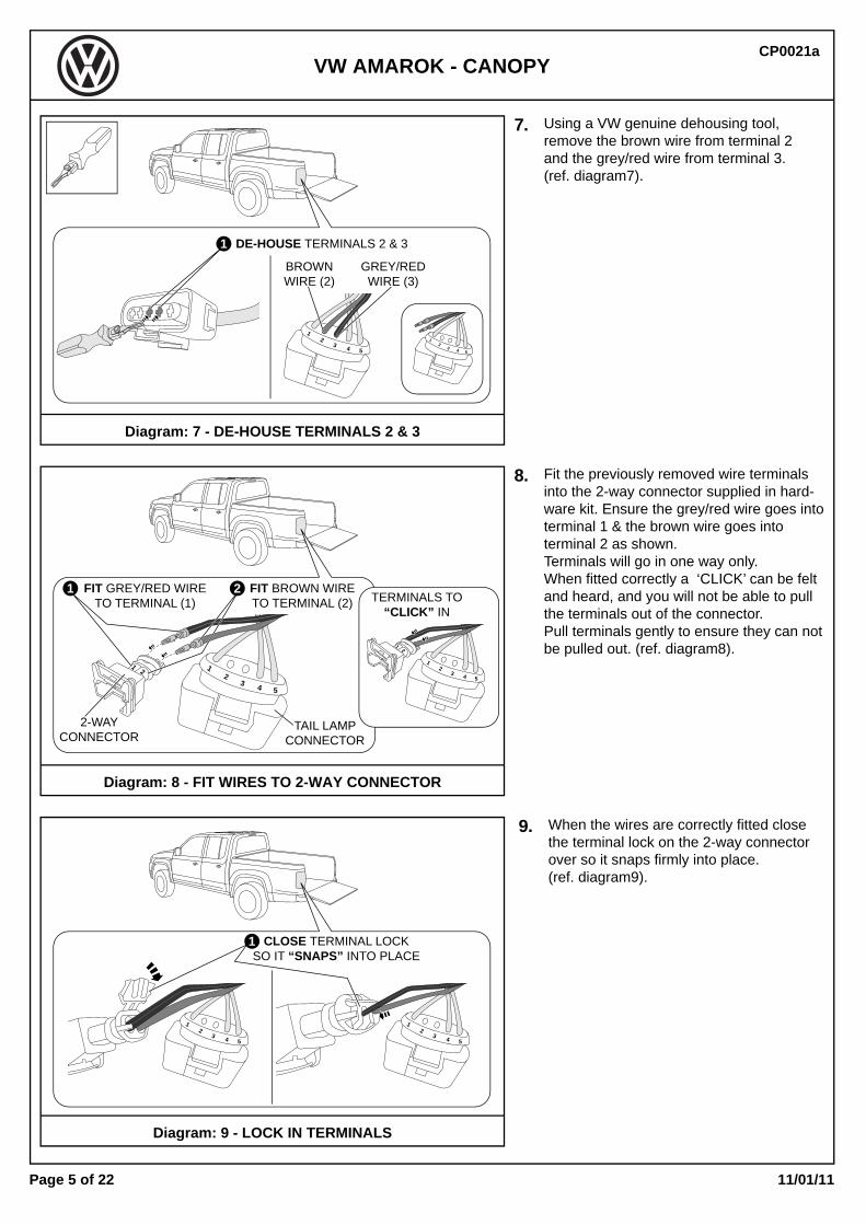
When the wires are correctly fitted closethe terminal lock on the 2-way connectorover so it snaps firmly into place.(ref. diagram9).
9.
Diagram: 9 - LOCK IN TERMINALS
Using a VW genuine dehousing tool,remove the brown wire from terminal 2and the grey/red wire from terminal 3.(ref. diagram7).
Fit the previously removed wire terminalsinto the 2-way connector supplied in hard-ware kit. Ensure the grey/red wire goes intoterminal 1 & the brown wire goes intoterminal 2 as shown.Terminals will go in one way only.When fitted correctly a ‘CLICK’ can be feltand heard, and you will not be able to pullthe terminals out of the connector.Pull terminals gently to ensure they can notbe pulled out. (ref. diagram8).
7.
Diagram: 7 - DE-HOUSE TERMINALS 2 & 3
8.
Diagram: 8 - FIT WIRES TO 2-WAY CONNECTOR
CLOSE TERMINAL LOCKSO IT “SNAPS” INTO PLACE
FIT GREY/RED WIRETO TERMINAL (1)
FIT BROWN WIRETO TERMINAL (2)
TAIL LAMPCONNECTOR
2-WAYCONNECTOR
DE-HOUSE TERMINALS 2 & 3
BROWNWIRE (2)
GREY/REDWIRE (3)
12
3 4 5
1
12
3 4 5
12
3 4 5
1
2
1 2
1
2
12
3 4 5
TERMINALS TO“CLICK” IN
12
3 4 5
12
3 4 5
1

11/01/11Page 6 of 22
CP0021aVW AMAROK - CANOPY
Feed a draw wire through the gapbetween the sheet metal surfaces.Under the vehicle attach the draw wireto the end of the vehicle harness withthe black 2-pin connector and two (2)loose wires as shown.Pull the draw wire so the vehicle harnessconnector is accessible in the tail lampopening as shown.Remove the draw wire. (ref. diagram10).
Connect the vehicle harness connectorto the 2-way connector as shown.Ensure connectors ‘CLICK’ into placeand can not be pulled apart.Pull connectors gently to ensure theycan not be pulled out. (ref. diagram11).
10.
Diagram: 10 - USING A DRAW WIRE, FEED VEHICLE HARNESS
11.
Diagram: 11 - CONNECT VEHICLE HARNESS TO 2-WAY CONNECTOR
PULLVEHICLE HARNESS
INTO TAIL LAMP AREA
3
REMOVEDRAW WIRE
CONNECTVEHICLE HARNESS CONNECTOR TO 2-WAY CONNECTOR
1
TAIL LAMPCONNECTOR
2-WAYCONNECTOR
VEHICLE HARNESSCONNECTOR
1
2
12
3 4 5
1
2
12
3 4 5
Fit the two (2) loose wires from the vehicleharness into the terminals on the tail lampconnector as shown. Ensure the grey/redwire goes into terminal 3 & the brown wiregoes into terminal 2 as shown.Terminals will go in one way only.When fitted correctly a ‘CLICK’ can be feltand heard, and you will not be able to pullthe terminals out of the connector.Pull terminals gently to ensure they can notbe pulled out. (ref. diagram12).
12.
Diagram: 12 - FIT WIRES TO TAIL LAMP CONNECTOR
1
TAIL LAMPHARNESS
VEHICLEHARNESS
1
2
12
3 4 5
1
2
12
3 4 5
FIT VEHICLE HARNESS TERMINALSTO TAIL LAMP CONNECTOR TERMINALS 2 & 3
BROWNWIRE (2) GREY/RED
WIRE (3)
12
12
34
5
FEEDDRAW WIRE1
ATTACHVEHICLEHARNESS
2
12
12
34
5
4
2 ATTACH THIS END OFVEHICLE HARNESS

11/01/11Page 7 of 22
CP0021aVW AMAROK - CANOPY
Diagram: 14 - FIT FOAM TAPE TO 2-WAY CONNECTORS
Diagram: 13 - REPLACE TERMINAL LOCK
13.
14.
Re-fit the terminal lock into thetail lamp connector as shown.Ensure it is pushed all the way back in.(ref. diagram13).
Remove adhesive liner from the foam tapesupplied in the wiring harness hardware kitand wrap it around the 2-way connectorand vehicle harness connector as shown.(ref. diagram14).
REMOVE LINERFROM FOAM TAPE
SUPPLIED IN WIRINGHARNESS KIT
WRAP FOAM TAPE AROUND2-WAY CONNECTOR
RE-FIT TERMINAL LOCK1
12
3 4 5
1
2
Diagram: 15 - RE-CONNECT TAIL LAMP & FIT TO VEHICLE
15. Re-connect tail lamp connector to tail lamp.Neatly position harnesses inside the recessfor the tail lamp and re-fit tail lamp to thevehicle by locating it on the ball fixings andsliding the tail lamp to the right.Secure to the vehicle with the two (2)screws previously removed.Close the tailgate. (ref. diagram15).
4 CLOSE TAILGATE
SLIDETAIL LAMP TOTHE RIGHT TO
RE-FIT
2
RE-CONNECTTAIL LAMP CONNECTOR
RE-FIT2 SCREWS
3
12345
1

11/01/11Page 8 of 22
CP0021aVW AMAROK - CANOPY
Diagram: 18 - ROUTE VEHICLE HARNESS & REMOVE TERMINAL COVER
Diagram: 17 - USING A DRAW WIRE PULL HARNESS INTO ENGINE BAY
Diagram: 16 - RUN HARNESS ALONG CHASSIS RAIL
16.
17.
Run the vehicle harness along the chassisrail with existing wiring, up to the front lefthand wheel arch as shown. Fit cable ties tosecure the vehicle harness to the existingharness every 300-400mm. Trim excesscable tie length with side cutters.Ensure harness is run in a direct route fromthe rear of the vehicle to the front.(ref. diagram16).
Open and secure the bonnet.Feed a draw wire down through the enginebay in the rear left hand corner where theinner left hand front quarter panel meets thefirewall as shown.From inside the left hand front wheel arch,attach the end of the vehicle harness to thedraw wire. Using two (2) people, one personfeeding the vehicle harness and the secondperson to pull the draw wire until theharness is at the top of the engine bay.Ensure harness is positioned behind thesplash guard inside the wheel arch as shown.Remove the draw wire. (ref. diagram17).IMPORTANT: The wiring must be positionedagainst the firewall and avoid contact againstany pipes or other wiring under tension ofcanopy vehicle wiring harness.
Remove battery terminal block cover usinga flat blade screwdriver.Route the vehicle harness along side theexisting harness under the battery terminalblock cover to the terminal block as shown.Replace the battery terminal block cover.Remove terminal block cover carefullyso you do not break the clipping tags.(ref. diagram18).
18.
1 OPEN BONNET
ROUTE VEHICLE HARNESS
EXISTING HARNESS
REMOVETERMINAL BLOCK
COVER
REMOVEBATTERY TERMINAL
BLOCK COVER
FEED DRAW WIRE2ATTACH VEHICLE HARNESS
ROUTE HARNESS BEHINDSPLASH GUARD
CHASSISRAIL
4
3WHEEL ARCH
SPLASHGUARD
LH FRONT
RUNVEHICLE HARNESS ALONG CHASSIS
RAIL WITH EXISTING HARNESSS & SECURE WITH CABLE TIES
CHASSIS RAIL VEHICLEHARNESS
1
1REMOVE
BATTERY TERMINALBLOCK COVER
3
42

11/01/11Page 9 of 22
CP0021aVW AMAROK - CANOPY
21. Using the sharp end of an engineersscribe, remove and discard the terminalplug (cover) from the battery terminalblock as shown. (ref. diagram21).
Diagram: 21 - REMOVE TERMINAL PLUG (COVER)
Diagram: 20 - REMOVE TERMINAL LOCK FROM BATTERY
19.
20.
IMPORTANT: Note the positions ofthe fuses.Remove fuses and store in a safe placeto re-fit at a later stage.(ref. diagram19).
Remove the terminal lock from thebattery terminal block as shown.(ref. diagram20).
Diagram: 19 - NOTE POSITION OF FUSES & REMOVE
NOTE FUSEPOSITIONS
REMOVETERMINAL LOCK
1
REMOVEFUSES
2
REMOVE & DISCARDTERMINAL PLUG (COVER)

11/01/11Page 10 of 22
CP0021aVW AMAROK - CANOPY
24. Re-fit the fuses to previously noted positions.Fit the 5 amp fuse from the wiring harnesshardware kit, to the vehicle harness terminalposition as shown. (ref. diagram24).
Diagram: 24 - RE-FIT FUSES & FIT 5 AMP FUSE FROM KIT
22.
23.
Fit the vehicle harness terminal into thebattery terminal block as shown.Terminal will go in one way only.When fitted correctly a ‘CLICK’ can be feltand heard, and you will not be able to pullthe terminal out of the block.Pull terminal gently to ensure it can notbe pulled out. (ref. diagram22).
Re-fit the terminal lock into thebattery terminal block as shown.Ensure it is pushed all the way back in.(ref. diagram23).
Diagram: 23 - RE-FIT TERMINAL LOCK TO BATTERY
Diagram: 22 - CONNECT VEHICLE HARNESS TO TERMINAL
RE-FIT FUSES TONOTED POSITIONS
1
FIT5 AMP FUSE
FROM KIT
2
RE-FITTERMINAL LOCK
FIT VEHICLE HARNESS TERMINALINTO BATTERY TERMINAL BLOCK
VEHICLE HARNESS

11/01/11Page 11 of 22
CP0021aVW AMAROK - CANOPY
27. Using alcohol wipe provided clean thetop surface of the front rail and wipeaway residue with a dry clean cloth.If heavy cleaning is required use Iso-Propyl alcohol and wipe away residuewith a dry clean cloth.Apply (MISC1365) primer stick along halfthe rear edge width of the front tub rail asshown and allow to dry. Starting with a small amount of the tapefrom the double sided tape roll 12mm wide(TAPE0615), apply it starting from thecorner of the front rail to the other side,along the rear edge of the front tub railpressing down on the liner as you applythe tape across the vehicle as shown.Apply firm pressure to ensure the tapeadheres to the vehicle.(ref. diagram27).Diagram: 27 - FIT 3M TAPE 12x1700mm
FRONT RAIL
APPLYDOUBLE SIDED 12x1700mm ROLL(TAPE0615) ACROSS FRONT RAIL
1
4
POSITION TAPEAGAINST SIDE RAIL
2
3
FRONT RAIL OFVEHICLE TUB
SIDE RAIL OFVEHICLE TUB
APPLYPRIMER STICK
TO SHADED AREAALONG FRONT RAIL
2
POSITIONTAPE ON EDGE
OF RADIUS
FRONTRAIL
25.
26.
Re-fit the terminal cover.Close the bonnet(ref. diagram25).
Thoroughly clean and dry installationareas (tub, rear of cabin and glass)as shown.Clean front of canopy including the frontwindowUsing cardboard cut from the canopycarton, cut and place a piece inside thetub on the floor as a protection mat whileinstalling the canopy. (ref. diagram26).
Diagram: 26 - CLEAN & DRY INSTALLATION AREAS
Diagram: 25 - RE-FIT TERMINAL COVER
POSITIONCARDBOARD TUBPROTECTION MAT
2
13
2 CLOSE BONNET
RE-FITTERMINAL
BLOCK COVER
TERMINAL BLOCK
1

11/01/11Page 12 of 22
CP0021aVW AMAROK - CANOPY
RAIL EXTRUSION TUB STOP
28.
29.
Using a non permanent marker, measureand mark a line at the centre of the railextrusion tub stop (ALUM0043-1) and thecentre of the front rail on the tub as shown.Use alcohol wipes provided clean the tapecontact surfaces of the rail extrusion tubstop and wipe away residue with a dryclean cloth.Apply (MISC1365) primer stick to high-lighted area over full length of the railand allow it to dry. (ref. diagram28).
Remove the liner film from the double sidedtape applied to the rail extrusion tub stop.Fit rail extrusion tub stop (ALUM0043-1)to the front rail over the tape aligning thepreviously marked centre lines.IMPORTANT: Ensure the short face sitsover the front rail, and the long face withslots overhangs into the tub as shown.Apply firm pressure forward and down onthe rail extrusion tub stop along the lengthto ensure maximum adhesion of the foamtape. (ref. diagram29).
Diagram: 29 - FIT FRONT TUB STOP EXTRUSION
Diagram: 28 - CENTRE & CLEAN FRONT TUB STOP EXTRUSION
APPLYFIRM PRESSURE TO
ADHERE TAPEREMOVE
TAPE LINER1
FITRAIL EXTRUSION TUB STOP
RAIL EXTRUSIONTUB STOP
TAPE
CROSS SECTIONTHROUGH FRONT RAIL
FRONTRAIL
2
3
1 2 MEASURE & MARKCENTRE LINE OF RAILEXTRUSION TUB STOP
MEASURE & MARKCENTRE LINE OF FRONT RAIL
= =
30. Mark and drill eight (8) Ø5mm holes intothe front rail tub stop and tub rail usingdimension’s as shown.Rivets must secure to flat form on tub.Apply rust inhibitor to all drilled holes inthe tub sheet metal.Secure with eight (8) stainless steel rivetsas shown. (ref. diagram30).
Diagram: 30 - SECURE FRONT TUB STOP RAIL
FIT EIGHT (8) RIVETS
200
100200200 200 200200200
Ø5mmRust
Inhibitor
(x8)2 3 4
4
34

11/01/11Page 13 of 22
CP0021aVW AMAROK - CANOPY
23
4
5
6
Apply EPDM foam tape (TAPE0386) fromhardware kit to the vehicle tub bed rails andrail extrusion tub stop.IMPORTANT: DO NOT CUT FOAM TAPE!Starting from one side at the rear corner,position the tape end in line with theedge of the tub rail, position the foamtape on the edge of the rear radiusof the tub and as it bends around thecorner align it to the edge of the insideradius of the top tub rail and continuethis position all the way along the siderail in one continuous length, position22mm rearward along the rail extrusiontub stop as shown and to the edge ofthe inside radius of the top tub rail downthe other side, run tape out onto the tail-gate as shown. As the tape bends aroundthe corners ensure the tape sits flat andDOES NOT pucker. Trim off excess to theedge of the tub rail as shown.Ensure all foam tape areas are fully adheredto the tub and tub stop by applying moderatepressure down on the tape all the wayaround the tub. (ref. diagram32).Tape MUST be fully adhered to tub railsand tub stop, and sit flat in onecontinuous length to prevent waterentering the canopy.
32.
Diagram: 32 - INSTALL WATER SEALING TAPE
APPLYEPDM FOAM TAPEAROUND BED RAIL
TAILGATE OFVEHICLE TOP VIEW OF
VEHICLE TUB
CA
BIN
OF
VEH
ICLE
START AT THEEDGE OF THE
TUB RAIL ON THEREAR EDGE RADIUS
SECTION ATREAR OFVEHICLE
POSITIONEPDM FOAM TAPEON THE EDGE OF
THE INSIDE RADIUSALONG THE SIDE RAILS
POSITIONEPDM FOAM TAPE
22mm REARWARD OFTHE EDGE OF THERAIL EXTRUSION
TUB STOP
ALONGSIDE RAILS
ALONGSIDE RAILS
FOAM TAPE MUST NOTPUCKER AROUND CORNERS
FINISH OVERTHE EDGE OFTHE TAILGATE
TRIM EXCESS TOTHE EDGE OFTHE TUB RAIL
ALONG FRONT RAILWITH TUB STOP
22mm
31. Using alcohol wipes provided clean alltop rail areas of the bed liner and wipeaway residue with a dry clean cloth.If heavy cleaning is required use Iso-Propyl alcohol and wipe away residuewith a dry clean cloth.(ref. diagram31).
Diagram: 31 - VEHICLE SURFACE PREPARATION
1
11/01/11Page 14 of 22
CP0021aVW AMAROK - CANOPY
NOT SUPPLIED
NOT SUPPLIED
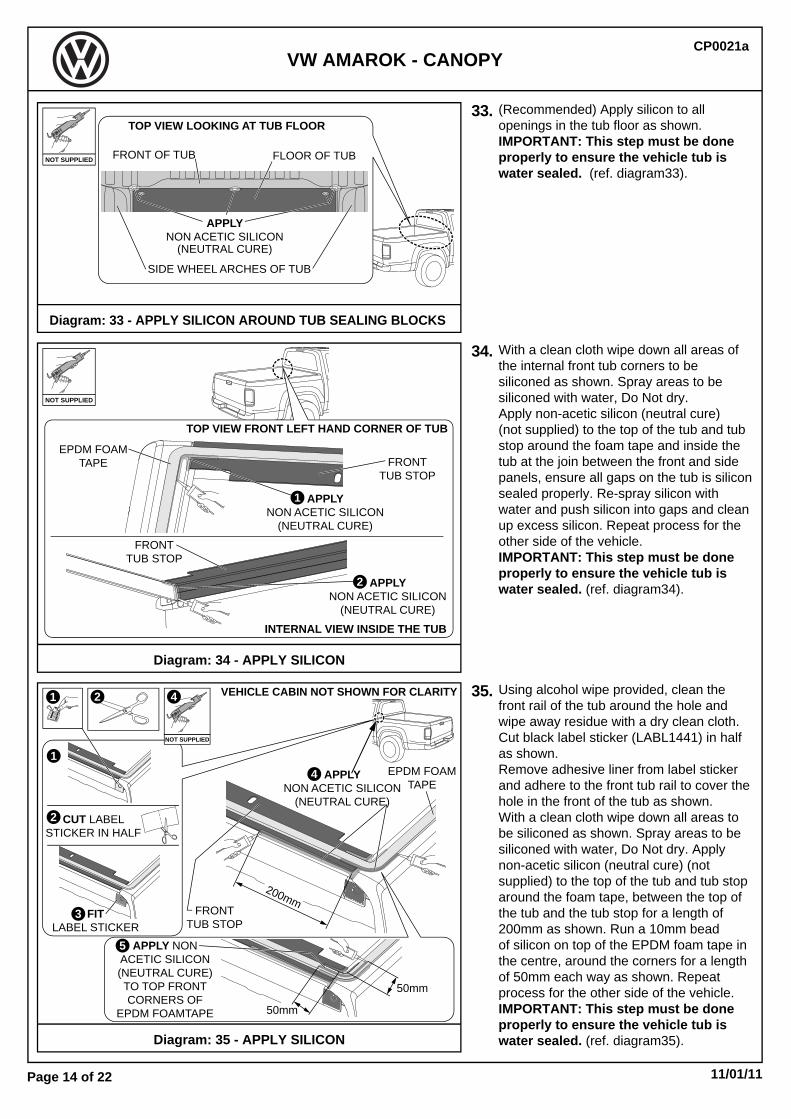
35. Using alcohol wipe provided, clean thefront rail of the tub around the hole andwipe away residue with a dry clean cloth.Cut black label sticker (LABL1441) in halfas shown.Remove adhesive liner from label stickerand adhere to the front tub rail to cover thehole in the front of the tub as shown.With a clean cloth wipe down all areas tobe siliconed as shown. Spray areas to besiliconed with water, Do Not dry. Applynon-acetic silicon (neutral cure) (notsupplied) to the top of the tub and tub stoparound the foam tape, between the top ofthe tub and the tub stop for a length of200mm as shown. Run a 10mm beadof silicon on top of the EPDM foam tape inthe centre, around the corners for a lengthof 50mm each way as shown. Repeatprocess for the other side of the vehicle. IMPORTANT: This step must be doneproperly to ensure the vehicle tub iswater sealed. (ref. diagram35).Diagram: 35 - APPLY SILICON
Diagram: 34 - APPLY SILICON
FITLABEL STICKER
33.
34.
(Recommended) Apply silicon to allopenings in the tub floor as shown.IMPORTANT: This step must be doneproperly to ensure the vehicle tub iswater sealed. (ref. diagram33).
With a clean cloth wipe down all areas ofthe internal front tub corners to besiliconed as shown. Spray areas to besiliconed with water, Do Not dry.Apply non-acetic silicon (neutral cure)(not supplied) to the top of the tub and tubstop around the foam tape and inside thetub at the join between the front and sidepanels, ensure all gaps on the tub is siliconsealed properly. Re-spray silicon withwater and push silicon into gaps and cleanup excess silicon. Repeat process for theother side of the vehicle.IMPORTANT: This step must be doneproperly to ensure the vehicle tub iswater sealed. (ref. diagram34).
Diagram: 33 - APPLY SILICON AROUND TUB SEALING BLOCKS
NOT SUPPLIED
APPLYNON ACETIC SILICON
(NEUTRAL CURE)
EPDM FOAMTAPE
FRONTTUB STOP
VEHICLE CABIN NOT SHOWN FOR CLARITY2
2
3
CUT LABELSTICKER IN HALF
1
4
4
1
200mm
EPDM FOAMTAPE
TOP VIEW FRONT LEFT HAND CORNER OF TUB
INTERNAL VIEW INSIDE THE TUB
APPLYNON ACETIC SILICON
(NEUTRAL CURE)
FRONTTUB STOP
FRONTTUB STOP
1
APPLYNON ACETIC SILICON
(NEUTRAL CURE)
2
APPLYNON ACETIC SILICON
(NEUTRAL CURE)
FRONT OF TUB
TOP VIEW LOOKING AT TUB FLOOR
FLOOR OF TUB
SIDE WHEEL ARCHES OF TUB
50mm
50mm
APPLY NONACETIC SILICON(NEUTRAL CURE)TO TOP FRONTCORNERS OF
EPDM FOAMTAPE
5

11/01/11Page 15 of 22
CP0021aVW AMAROK - CANOPY
DO NOT SLIDE CANOPYON EPDM FOAM TAPE
AND SILICON
2 FITCANOPY TO
VEHICLE
1 TAPEWIRING HARNESS
TO LH SIDE WINDOW
3FEED
CANOPY HARNESSBETWEEN TUB AND
CABIN DOWN TOCHASSIS RAIL
HARNESS
36. Approximate weight of canopy 70Kg.Two people (minimum) are required forthis step.First tape the wiring harness to the lefthand side window with masking tape.Position the canopy onto the vehicletub carefully. IMPORTANT: Ensure canopy is placedfully forward on the tub in one action.DO NOT slide the canopy on the EPDMfoam tape and silicon, as this candamage the foam tape and spread thesilicon (break the water seal).Remove masking tape and feed canopyharness down between tub and cabin (righthand side of vehicle) so it is accessibleunder the vehicle on the outside of thechassis rail. (ref. diagram36).
Diagram: 36 - FIT CANOPY TO TUB
37. Align the canopy evenly on the tub.Canopy front face of extrusion should be15mm from the edge of the tub stop railas shown.Open rear tailgate to check sidewaysalignment. Using a steel rule position thecanopy so both canopy base side railsare even to the width of the vehicle tub.(ref. diagram37).
Diagram: 37 - ALIGN CANOPY TO TUB
EVEN BOTH SIDESAT THE END CAPS
CANOPY BASE RAIL
FRONT EDGE OF TUB STOPRAIL (ALUM0043-1)
VIEW FROMREAR OF CAR
15mm FROM FRONT OF CANOPYTO EDGE OF TUB STOP RAIL
15mm
0mm 10 20 30 40 50 60 70 80 90
38. Fit six (6) clear tape 50x3mm abrasion resistant, to the vehicle tub rails directlyunder the square holes in the canopy baserails for the clamps as shown. Orient thetape so the long edge runs the length ofthe vehicle as shown. Position half of thetape on the front face of the rail and foldthe remaining half around onto the backof the rail. (ref. diagram38).
Diagram: 38 - FIT CLEAR ABRASION TAPE TO TUB
FIT6 CLEAR TAPE
50x3mm ABRASIONRESISTANT TO TUB
RAILS DIRECTLYUNDER CLAMP HOLES
IN BASE RAILS
ORIENTSO THE LONG EDGERUNS THE LENGTHOF THE VEHICLE
+70Kg
11/01/11Page 16 of 22
CP0021aVW AMAROK - CANOPY
LOCTITE277
DISASSEMBLE4 CLAMPS
1
FITREMAINING CLAMPS
APPLYLOCTITE 277 TO BOLTS
23
TIGHTEN2 - REAR CLAMPSTORQUE TO 9Nm
4TIGHTEN
2 - FRONT CLAMPSTORQUE TO 9Nm
5TIGHTEN
2 - MIDDLE CLAMPSTORQUE TO 9Nm
10mm
TIGHTEN TOTORQUE 6Nm
2
FITBOLT AND WASHER
SECURENYLOC NUT
AND WASHER
WASHER
NYLOC NUT
CANOPY BASERAIL AT FRONT
1
VEHICLEFRONT TUB
SHEET METAL
6Nm
10mm
9Nm
13mm
2
13mm
39.
40.
41.
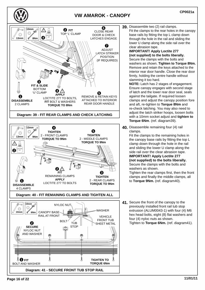
Disassemble two (2) rail clamps.Fit the clamps to the rear holes in the canopybase rails by fitting the top L clamp downthrough the hole in the rail and sliding thelower U clamp along the side rail over theclear abrasion tape.IMPORTANT! Apply Loctite 277(not supplied) to the bolts liberally.Secure the clamps with the bolts andwashers as shown. Tighten to Torque 8Nm. Remove and retain the keys attached to theinterior rear door handle. Close the rear doorfirmly, holding the centre handle withoutslamming it too hard. NOTE: Latch has 2 stages of engagement.Ensure canopy engages with second stageof latch and the lower rear door seal, sealsagainst the tailgate. If required loosenclamps and adjust the canopy position foreand aft, re-tighten to Torque 8Nm andre-check latching. You may also need toadjust the latch striker hoops, loosen boltswith a 10mm socket adjust and tighten toTorque 6Nm. (ref. diagram39).
Disassemble remaining four (4) railclamps.Fit the clamps to the remaining holes inthe canopy base rails by fitting the top Lclamp down through the hole in the railand sliding the lower U clamp along theside rail over the clear abrasion tape.IMPORTANT! Apply Loctite 277(not supplied) to the bolts liberally.Secure the clamps with the bolts andwashers as shown. Tighten the rear clamps first, then the frontclamps and finally the middle clamps, allto Torque 9Nm. (ref. diagram40).
Secure the front of the canopy to thepreviously installed front rail tub stopextrusion (ALUM0043-1) with four (4) M6hex head bolts, eight (8) flat washers andfour (4) nyloc nuts as shown.Tighten to Torque 6Nm. (ref. diagram41).
Diagram: 41 - SECURE FRONT TUB STOP RAIL
Diagram: 40 - FIT REMAINING CLAMPS AND TIGHTEN ALL
DISASSEMBLE2 CLAMPS
FITTOP ‘L’ CLAMP
1
2
4
FIT & SLIDEBOTTOM
‘U’ CLAMPAPPLY
LOCTITE 277 TO BOLTS,FIT BOLT & WASHERS
TORQUE TO 8Nm
6CLOSE REAR
DOOR & CHECKLATCHES ENGAGE
5REMOVE & RETAIN KEYSATTACHED TO INTERIOR
REAR DOOR HANDLE
7ADJUST
LATCH STRIKERPOSITION
(IF REQUIRED)
LOCTITE277
3
8Nm
13mm
413mm
Diagram: 39 - FIT REAR CLAMPS AND CHECK LATCHING
BOLT TUBSTOP
11/01/11Page 17 of 22
CP0021aVW AMAROK - CANOPY
CLEARABRASION
TAPE
TRIMEXCESS CLEARABRASION TAPE
3
REMOVEMASKING TAPE
CANOPY NOT SHOWN FOR CLARITY
5
SQUEEGEE OUTEXCESS SOLUTION
BUBBLES
41
25% ISOPROPYLALCOHOL
75% WATER
APPLYCLEAR
ABRASION TAPE
ALIGNBOTTOM EDGE
OF CLEAR ABRASIONTAPE WITH TOP EDGE
OF MASKING TAPE
TAILGATE
REARDOOR SASH
MASKINGTAPE
REAR WINDOW
2
APPLYMASKING TAPETO TAILGATE
1
42.
43.
44.
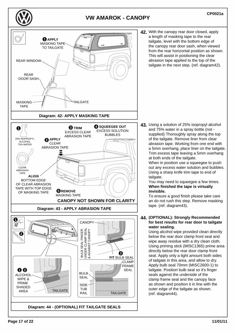
With the canopy rear door closed, applya length of masking tape to the reartailgate, level with the bottom edge ofthe canopy rear door sash, when viewedfrom the rear horizontal position as shown.This will assist in positioning the clearabrasion tape applied to the top of thetailgate in the next step. (ref. diagram42).
Using a solution of 25% isopropyl alcoholand 75% water in a spray bottle (not -supplied) Thoroughly spray along the topof the tailgate. Remove liner from clearabrasion tape. Working from one end witha 5mm overhang, place liner on the tailgate. Trim excess tape leaving a 5mm overhangat both ends of the tailgate.When in position use a squeegee to pushout any excess water solution and bubbles.Using a sharp knife trim tape to end oftailgate.You may need to squeegee a few times.When finished the tape is virtuallyinvisible. To ensure a good finish please take carean do not rush this step. Remove maskingtape. (ref. diagram43).
(OPTIONAL): Strongly Recommendedfor best results for rear door to tailgatewater sealing. Using alcohol wipe provided clean directlybelow the rear door clamp front seal andwipe away residue with a dry clean cloth.Using priming stick (MISC1365) prime areadirectly below the rear door clamp frontseal. Apply only a light amount both sides of tailgate in this area, and allow to dry. Apply bulb seal 70mm (MISC2600-1) totailgate. Position bulb seal so it's fingerseals against the underside of theclamp frame seal and the canopy faceas shown and position it in line with theouter edge of the tailgate as shown.(ref. diagram44).
Diagram: 44 - (OPTIONAL) FIT TAILGATE SEALS
Diagram: 43 - APPLY ABRASION TAPE
Diagram: 42- APPLY MASKING TAPE
BULBSEAL
BU
LB S
EA
L FI
NG
ER
UN
DE
R C
LAM
P S
EA
L&
AG
AIN
ST
CA
NO
PY
CLAMPFRAMESEAL
TAILGATE
SIDETUBRAIL
CANOPY
FIT BULB SEAL
ALCOHOLWIPE &PRIME
SHADEDAREA
1 2
3
TAILGATE
1
2

11/01/11Page 18 of 22
CP0021aVW AMAROK - CANOPY
CHECKCANOPY LAMP
WORKS
45.
46.
47.
Feed the canopy harness along thechassis rail to the vehicle harnessconnector, and connect them together.IMPORTANT: Wiring harnesses shouldbe positioned away from the exhaustsystem side. (ref. diagram45).
Two people are required to check thecanopy brake light is operational afterdepressing the brake pedal.Then open the rear window and checkthat the internal canopy lamp is operatingcorrectly when switched to the ’ON’position only.NOTE: An additional accessory can beordered from EGR to turn the light onin ‘DOOR’ position of the switch when thedoor is opened automatically.(ref. diagram46).
Using alcohol wipe provided in the kit,clean the left hand side top corner of thefront tub rail as shown, and wipe awayresidue with a dry clean cloth.Remove tape liner from adhesive tie padand position on the tub in area previouslycleaned as shown. Apply pressure toensure maximum adhesion.(ref. diagram47).
Diagram: 47 - FIT ADHESIVE TIE PAD
Diagram: 46 - CHECK BRAKE LIGHTS AND CANOPY LIGHT
Diagram: 45 - CONNECT VEHICLE & CANOPY CONNECTORS
CANOPY
CABIN
TUB
1FIT
ADHESIVETIE PAD
2
CHECKBRAKE LIGHTS
WORK
CONNECTCANOPY HARNESS TO VEHICLE HARNESS
1
CHASSIS RAIL

11/01/11Page 19 of 22
CP0021aVW AMAROK - CANOPY
PLACE FITTING INSTRUCTIONSIN THE CUSTOMERS LOG BOOK
Diagram: 50 - FINAL CLEANING
Diagram: 49 - WATER LEAK TESTING
Diagram: 48 - SECURE CANOPY HARNESS
48.
49.
50.
Fit a cable tie through the adhesive tiepad previously fitted to the front of thetub and secure the canopy wiring harnessas shown. Trim excess tie with sidecutters. (ref. diagram48).
Water test canopy checking for water leaks.Test both canopy keys work to lock andunlock the rear door and side lift up window.Open both side windows.If the rear door handle does not lock,remove the interior lock cover, unclip thepull rods and wind to lengthen them slightly.Re-check rear door lock function.When rear door locks replace interior lockcover, and add the canopy keys to the customers vehicle keys. (ref. diagram49).
Clean canopy including all windowsand vehicle thoroughly .Place fitting instructions in theCustomers log book, and ensurepages 20 and 21 of these instructionsare discussed with the customer anda copy is given to the customer. (ref. diagram50).
DETAILS TO ADJUST PULLRODSADJUST LENGTH
OF PULLRODS BY ROTATION
ANTI-CLOCKWISE = LENGTHEN
3
REMOVE INTERIORLOCK COVER
UNCLIP PULLRODSFROM RETAINER CLIPS
REPLACE INTERIOR LOCK COVER
RE-CHECKLOCK
FUNCTION
4
CLIP PULLRODSINTO RETAINER CLIPS52
16
FITCABLE TIE
CABIN
CANOPY
TUB
11/01/11Page 20 of 22
CP0021aVW AMAROK - CANOPY
WARNING! - SAFETY!• Do Not use the canopy as a passenger compartment.• Do Not operate/drive vehicle with fold up windows or rear door open. They must be closed when vehicle is in motion.• Do Not store or transport volatile materials, such as solvents, chemicals or liquids as fumes may accumulate inside canopy. Do Not allow solvents, chemicals or oils to come in contact with the canopy. If this should occur clean the canopy immediately with a mild detergent and water solution.• Do not stand/sit or rest heavy objects on Canopy.• Do not fill volatile liquid containers while inside canopy such as fuel cans.• VEHICLES FITTED WITH A BED LINER: Static electricity can cause fire when fuel is pumped into ungrounded fuel containers or equipment (eg: motorcycles, chainsaws etc..). Do Not fill fuel containers or equipment within the vehicle tray as static electricity can cause fuel to ignite, resulting in damage, injury or death. To avoid electricity build-up, place fuel container or equipment on the ground before filling.
MaintenanceOnly use mild detergents or wax polish. Do Not use abrasive compounds on painted or plastic finishedcanopy surfaces.The gas struts are self lubricating and should only be cleaned with a damp cloth, when regularly cleaningthe vehicle. Premature seal failure will result if solvents or lubricants are used to clean struts.Gas struts must be orientated as installed, cylinder (wide end) to canopy and rod (narrow end) to glass.Lightly coat the door and window rubber assemblies with a silicon spray after cleaning periodically.Only locks and lock recesses are to be lubricated with Graphite Powder.Vaseline may be used on the rotary catches on the rear door.DO NOT use any other lubricants or oils. Using alternative products will VOID Warranty.Check canopy attachment clamps every 1000 Km.Clamp bolt recommended torque setting is (9 Nm or 6.64 lb/ft).If removed, bolts must have LOCTITE 277 re-applied and be re-tightened on refitting to specified values.CHECK regularly that all screws and fasteners holding windows and doors are tight.The rear tailgate protection tape must be replaced periodically to minimize paint scuffing caused by the canopy rear door opening and closing.For sliding windows use a silicon based Non-Aerosol lubricant or a dry film lubricant or LY70 lubricant or 3Mwindow channel dresser lubricant sparingly. DO NOT use CRC, WD40 or petroleum based lubricants on sliding windows.
Warranty TermsEGR warrants that the ABS Canopy will be free from defects in material and workmanship for a period of three (3) years from the retail date ofpurchase. The gas struts are warranted for one (1) year from the retail date of purchase.This warranty only applies to the original purchaser and is nontransferable. Warranty must be claimed with original sales receipt for proof of purchase.
ExclusionsThis warranty does not cover failure due to neglect, improper installation, including any modifications to installation hardware, alterations, additionof non genuine equipment, abuse, accident, normal wear and tear, lack of maintenance, misuse, and exposure to chemicals that are not safe forplastics or hardware components. Incidental or consequential damage or loss of contents due to use, neglect, lack of maintenance, misuse of EGR Canopy is sole responsibility ofthe vehicle owner and operator. Paint wear to the vehicle bed can happen with any Canopy and is the sole responsibility of the vehicle owner.Paint damage to your vehicle is not covered under this warranty.
DisclaimerIn the event that your EGR Canopy is found to be defective under the terms of this warranty, it is at the discretion of EGR to repair or replace thedefective part. Transportation costs and labour are not associated with this warranty claim.
OWNERS MANUAL SUPPLEMENTIMPORTANT: PLACE THIS PAGE IN THE CUSTOMER’S
VEHICLE SERVICE BOOK.

11/01/11Page 21 of 22
CP0021aVW AMAROK - CANOPY
KEY IDENTIFICATION CODE
1234
VW Amarok MY10 Onwards CANOPY
Please write the key identification code in the boxes above,and retain this copy with the vehicle service history.
Replacement keys can be purchased from your local dealer.
OWNERS MANUAL SUPPLEMENTIMPORTANT: PLACE THIS PAGE IN THE CUSTOMER’S
VEHICLE SERVICE BOOK.

11/01/11Page 22 of 22
CP0021aVW AMAROK - CANOPY
Dealer Name:
Model:
Order Date:
Required By:
Canopy Colour
Canopy Checklist - Details of rectifications required: KEY No. :
Vehicle Damage Check: Detail:
Dealer Code:
Stock No:
Order No:
Vin No:
1. Check paint on canopy
2. Cleanliness of canopy inside and outside
3. Canopy sealing to tray, front tub stop extrusion and foam tape applied correctly
4. Seal around Front of tub, vertical & floor with Silicone after foam tape applied
5. Tailgate clear abrasion wear tape fitted
6. Position canopy on tub squarely side to side, rear door closes on second stage latch (not just first latch) both sides and lower door sash seal, seals to tailgate, adjust strikers and /or door latch pull rods via access to centre door handle by removing internal door handle cover
7. Clamps are square and tight (Torque 9Nm)
8. IMPORTANT! Loctite 277 applied to all Clamp Bolt Threads
9. Rear Door, Side Door’s and Front window operation, side windows lock with keys. Check rear door handle and locks with keys. If not locking remove interior cover on rear door handle and adjust the pull rods by winding them in/out and test the door again, replace cover.
10. Operation of Brake Light
11. Operation of interior light
12. Water Tested for leaks
13. Clean up of work area
14. Comment
Record Canopy Serial Number: Checked By:
Vehicle received and Checked by Dealer Staff:
Fitted By:
INSTALLATION CHECKLIST
(located on inside LH rear pillar of canopy shell)