can passivhaus standards be met in the uk using ... · can passivhaus standards be met in the uk...
TRANSCRIPT

Can Passivhaus standards be met in the UK using
traditional cavity wall construction?
By
Michael Corran
Submitted in partial fulfilment
of the requirement for the degree
BSc(Hons) Construction Management
Leeds Metropolitan University
May 2012

i
Abstract
The UK Government has set an ambitious 80% reduction in greenhouse gas emissions
by 2050. The residential sector is responsible for 30% of the UK’s total carbon dioxide
emissions and is the focus for much of the Government’s efforts to reduce emissions.
The Code for Sustainable Homes, backed by the requirements of Part L1A, is the means
by which the UK Government is seeking to reduce emissions and energy consumption
in the domestic sector. An alternative, more ambitious, approach widely employed in
northern Europe is ‘Passivhaus’, which shows reduced energy demands of around 75%
compared to the German housing stock. The majority of these existing Passivhaus
certified dwellings use techniques (mostly timber frame, concrete and masonry with
external cladding), common to the country in which they are built, because of the
knowledge and skills present.
Masonry cavity wall construction comprises of 65% of the UK’s housing stock and is
the method most familiar to UK builders. This dissertation examines whether
Passivhaus standards can be met using traditional masonry cavity wall construction in
the UK. Denby Dale is the only current certified Passivhaus certified dwelling built
using cavity wall construction in the UK. The dissertation evaluates the way in which
the Denby Dale construction has been adapted to meet Passivhaus requirements and
using monitoring data collected by Leeds Met researchers, along with an interview with
the residents, assesses whether Passivhaus standards are met once the dwelling is
occupied.
Secondary research shows that the dwelling’s constructional aspects (walls, roof,
ground floor and windows) concerning heat transfer coefficients, thermal bridging and
airtightness are all within Passivhaus requirements and are acceptable. The mechanical
ventilation and heat recovery (MVHR) system efficiency is extremely high and easily
conforms to the Passivhaus standard. The primary research shows that the Passivhaus
requirements for primary energy demand, space heating demand, airtightness, thermal
comfort and indoor air quality have all been met.
The research shows not only that Passivhaus standards can be met using traditional
masonry cavity wall construction in the UK, but also that a 56% to 76% reduction in
emissions is possible compared to Part L 2010 UK Building Regulations. The
implications of these findings are discussed and a number of recommendations made.
The overall conclusion is that, although Passivhaus may be able technically to be
adapted to UK housebuilding techniques, there are still a number of constraints that
could affect its widespread uptake in the UK despite the undoubted benefits that it has
been shown to offer.

ii
Acknowledgements
I firstly owe my gratitude to John Bradley who has given me the opportunity to work on
this fascinating and current subject. John has not only been fantastic in this final year,
but also throughout my University experience. I am hugely appreciative of his
continued support and efforts. I cannot only say that John’s efforts and positive
approach have been acknowledged by me, but also by all students on the course. John is
a credit to the University and I wish him all the best for the future.
I would like to thank Leeds Metropolitan researchers, and in particular Ruth Sutton,
who have allowed me to use monitored data in relation to Denby Dale and have given
advice regarding this dissertation.
Much admiration goes to the Denby Dale residents who have taken a unique and
admirable step to transferring the Passivhaus concept to the UK. I would like to thank
them for their time and cooperation in relation to the interview, which has provided a
vital insight to the advantages Passivhaus has to offer. Furthermore I would like to
thank them for their consent, allowing me to use data related to their dwelling.
Finally I would like to thank my family who have provided endless support, allowing
me to be in the position of which I am now.

iii
Contents
Section Page
Abstract i
Acknowledgements ii
Contents page iii
List of Tables vi
List of Figures vii
Abbreviations ix
Chapter 1: Introduction 1
1.1 Problem Specification 1
1.2 Aim and Objectives 4
Chapter 2: Literature Review 5
2.1 What is Passivhaus? 5
2.2 Construction fundamentals 8
2.2.1 Good thermal insulation and compactness 9
2.2.2 Thermal bridging 9
2.2.3 Windows and doors 10
2.2.4 Airtightness 11
2.2.5 Mechanical ventilation and heat recovery (MVHR) 11
2.3 Passivhaus Planning Package software (PHPP) 12
2.4 Most common Passivhaus construction methods 12
2.5 UK housing construction methods 15
2.6 Conclusion 17
.
Chapter 3: Methodology 19
3.1 Introduction 19
3.2 Secondary research 19
3.3 Primary research 20

iv
Chapter 4: Research findings 1: Denby Dale construction methods
and detailing 22
4.1 Introduction 22
4.2 Foundations and ground floor 23
4.2.1 Passivhaus U-value requirement comparison 24
4.2.2 Airtightness detailing 25
4.3 Wall structure 27
4.3.1 Passivhaus U-value requirement comparison 29
4.3.2 Airtightness detailing 30
4.4 Roof structure 30
4.4.1 Passivhaus U-value requirement comparison 30
4.4.2 Airtightness detailing 30
4.5 Windows and doors 33
4.5.1 Passivhaus U-value requirement comparison 34
4.5.2 Airtightness detailing 36
4.5.3 Thermal bridging, THERM analysis 36
4.6 First floor construction and airtightness detailing 40
4.7 Airtightness testing 41
4.8 Mechanical ventilation and heat recovery system (MVHR) 42
4.9 Summary 43
Chapter 5: Research findings 2: Denby Dale performance 45
5.1 Introduction 45
5.2 Primary energy demand 46
5.2.1 Comparison to Passivhaus requirement 49
5.3 Carbon dioxide (CO2) emissions 49
5.3.1 Comparison of SAP and PHPP factors 52
5.4 Space heating demand 53
5.4.1 Comparison to Passivhaus requirement 58
5.5 Distribution of energy use 58
5.6 Indoor carbon dioxide (CO2) levels 60
5.7 Internal temperature 65
5.8 Internal relative humidity 68

v
5.9 Subjective assessment of maintenance, operations and comfort by
occupants 73
5.10 Summary 76
Chapter 6: Conclusions 78
6.1 Implications and Recommendations 81
Bibliography 84
Appendices 94

vi
List of Tables
Table …. … Page
1: Criteria for Passivhaus certification 6
2: Fresh air heating limitations 7
3: Passivhaus specification summary 8
4: Passivhaus requirements relating to construction fundamentals and MVHR
system 22
5: Denby Dale ground floor U-value calculations and Passivhaus U-value
insulation requirements 25
6: Denby Dale wall U-value calculations, with Passivhaus U-value insulation
requirements 29
7: Denby Dale roof U-value calculations, with Passivhaus U-value insulation
requirements 31
8: Denby Dale window specifications in relation to Passivhaus requirements 34
9: First Denby Dale blower door test results 42
10: Denby Dale annual energy usage, with Passivhaus requirement in relation to
primary energy demand 48
11: Denby Dale primary energy demand calculation 49
12: Primary energy usage and PHPP CO2 emission factors 51
13: Primary energy usage and SAP CO2 emission factors 51
14: Gas energy usage and solar thermal readings, required for annual DHW
estimation 54
15: Gas energy usage, solar thermal readings and boiler switched off, required for
annual gas cooking estimation 56
16: Denby Dale range and average CO2 levels (ppm) from 20/07/2010 to
06/01/2012 62
17: Highest average CO2 concentrations measured within Denby Dale 63
18: Lowest average CO2 concentrations measured within Denby Dale 64
19: Comparison of Passivhaus standards and Denby Dale’s performance 77

vii
List of Figures
Figure Page
1: Linear thermal conductivity Ψ ≤ 0.01 W/mK 9
2: Triple glazing window with an overall U-value of 0.8 W/m²K 9
3: Passivhaus construction methods in Austria 13
4: Passivhaus construction methods in Germany 13
5: Masonry wall with external cladding 14
6: Passivhaus wall detail timber construction 15
7: UK housing construction type by dwelling ages 16
8: Traditional cavity wall structure 17
9: Denby Dale foundations and ground floor, cross section 24
10: Service penetration at ground floor 26
11: Denby Dale cavity wall and cavity tray 27
12: Denby Dale cavity wall 28
13: Denby Dale roof and wall junction, cross section 33
14: Ecopassiv window 34
15: Denby Dale window detailing 35
16: Denby Dale window detailing, cross section 36
17: Denby Dale window junction, isotherms produced in THERM 37
18: Denby Dale window junction, colour infrared produced in THERM 38
19: Denby Dale window junction, colour flux magnitude produced in THERM 39
20: Denby Dale window junction, flux vectors produced in THERM 39
21: Denby Dale first floor junction, cross section 41
22: Blower door airtightness test 41
23: Denby Dale MVHR system 43
24: Denby Dale south elevation 46

viii
25: Comparison of carbon dioxide equivalent emissions produced from primary
energy usage 52
26: Denby Dale average daily energy consumption and generation 55
27: Denby Dale average daily energy consumption and generation 57
28: Specific energy consumption 58
29: Comparison of primary energy consumption: Denby Dale and UK homes 59
30: Denby Dale daily average CO2 concentrations 61
31: Denby Dale ventilation ducting 66
32: Denby Dale daily average temperatures external and internal 67
33: Denby Dale daily average RH for internal and external environments 69
34: Denby Dale external temperatures and internal humidity comparison 71
35: Relationship between lounge RH and external temperature 72
36: Denby Dale south elevation 95
37: Denby Dale south-east elevation 95
38: Denby Dale north elevation 96
39: Denby Dale Vaillant gas boiler and STHW storage tank 96
40: Denby Dale MVHR system in garage 97
41: Denby Dale supply and extract ducts 97
42: Denby Dale ground floor, plan 102
43: Denby Dale first floor, plan 103
44: Denby Dale north elevation 104
45: Denby Dale east elevation 105
46: Denby Dale south elevation 106
47: Denby Dale west elevation 107

ix
Abbreviations
ach Air changes per hour
AECB Association of Environment Conscious Buildings
BRE Building Research Establishment
CCC Committee on Climate Change
CO2e Carbon dioxide equivalent
CEPHEUS Cost Efficient Passive Houses as a European Standard
DCLG Department for Communities and Local Government
DECC Department of Energy and Climate Change
GBM Green Building Magazine
GBS Green Building Store
GDP Gross Domestic Product
GHG Greenhouse gases
HTC Heat transfer coefficient
HSE Health and Safety Executive
IBO Austrian Institute for Healthy and Ecological Building
IPCC Intergovernmental Panel on Climate Change
iPHA International Passive House Association
K Unit of measurement for temperature Kelvin
kWh Kilowatt hours
kWh/(m²/a) Kilowatt hours per square metre per annum
Kyoto GHGs Carbon dioxide, methane, nitrous oxide, sulphur hexafluoride,
hydrofluorocarbons and perfluorocarbons
MtCO2e Million tonnes of carbon dioxide equivalent
MVHR Mechanical ventilation and heat recovery
m²K/W (R-value) Square metre per Kelvin per watt

x
m³/pers/h Cubic metre per person per hour
NAU Northern Arizona University
NBT Natural building technologies
NHBC National House Building Council
N/mm² Newton per square millimetre
Pa Pascal
PE Primary energy
PEP Promotion of Passivhaus
PHI Passivhaus Institute
PHPP Passivhaus Planning Package
ppm Parts per million
RH Relative humidity
SPED Specific primary energy demand
U-value Heat transfer coefficient
Uf Frame U-value
Ug Glazing U-value
W/mK Watts per metre Kelvin
W/m² Watts per square metre
W/(m²K) Watt per square metre per Kelvin
W/person Watts per person
Ψ Psi, linear thermal transmittance
Ψg Psi, linear thermal transmittance of glazing to frame junction

1
Chapter 1: Introduction
1.1 Problem Specification
According to the Department of Energy and Climate Change (DECC, 2011a) the UK
emitted 566.3 MtCO2e of greenhouse gases (GHG) in 2009, representing only 2% of
global carbon emissions (IEA, 2011) yet, despite this, the UK has set some of the most
ambitious carbon emission reduction targets. The Climate Change Act 2008 sets out
legally binding targets committing the UK to reduce GHG emissions, and states ‘It is
the duty of the Secretary of State to ensure that the net UK carbon account for the year
2050 is at least 80% lower than the 1990 baseline.’ (Climate Change Act 2008, c.27).
The Stern Review (Stern, et al., 2006; Tol, 2006) was a major factor in persuading the
UK Government to adopt such a demanding target, Stern argued that stabilising GHG
concentrations between 450ppm and 550ppm CO2e would be manageable and at a
reasonable cost: ‘expected annual cost of emissions reductions consistent with a
trajectory leading to stabilisation at 500ppm CO2e is likely to be around 1% of GDP by
2050’ (Stern, et al., 2006, pp. xii). The research predicted, in economic terms, the
consequences of not adhering to this upper bound 550ppm CO2e target could lead to an
average reduction of 10% global GDP.
Stern et al. (2006) believe that atmospheric levels above 550ppm CO2e would most
likely see an increase to the global average temperature of 2˚C. To prevent this,
significant reductions in global GHG emissions must be made. Agreements on a set of
mutual responsibilities, considering costs and the ability to bear with them, will
contribute to the overall goal of reducing the risks of climate change. Richer countries
based on income, historic responsibility and per capita are expected to take
responsibilities for emission reductions of 60-80% by 2050 (ibid).

2
A report published by the Committee on Climate Change (CCC, 2008) states that an
80% reduction of GHG emissions by 2050 would be an appropriate measure to enable
the UK to contribute towards reducing global Kyoto GHG emissions by 50-60%. The
Climate Change Act introduced ‘carbon budgets’ which set the trajectory limits on total
GHG emissions over 5 year periods, and are also legally binding (DECC, 2012b). The
CCC (2008; 2010) recommends GHG reductions of at least 34% by 2020 against 1990
baseline levels, with further reductions to 42% if and when there is progress towards
agreements to reduce global emissions. The fourth carbon budget, 2023-27, requires
emission reductions of 50%, and a total of 60% by 2030, relative to a 1990 baseline
(DECC, 2011a). The CCC (2010) states that a further 60% reduction in GHGs will be
required between 2030 and 2050 to meet the 2050 target.
The UK residential sector released approximately 149 MtCO2 in 2010, accounting for
30% of the UK’s total CO2 emissions (DECC, 2012a).The sector has consequently been
on the Government’s agenda to drastically reduce its GHG emissions. The Government
is pressing to make an impact on energy usage and emissions within the UK domestic
sector by introducing strict regulations to be applied to new dwellings. However if the
UK housing stock is to reduce CO2 emissions in line with the Climate Change Act then
energy consumption in new builds must be dramatically reduced.
The Code for Sustainable Homes is one action taken by the Government to improve the
energy efficiency of UK homes and reduce related CO2 emissions. Building Regulations
Part L1A requires a 25% decrease in CO2 emissions from Part L 2006 which meets the
requirements of the Code for Sustainable Homes level 4. Levels 5 and 6 are geared to
meet 100% and true zero carbon reductions to meet future targets (DCLG, 2009).
Alternatively the German approach to sustainable building ‘Passivhaus’ has undergone
extensive research (CEPHEUS, 2001; Williamson, 2007) which has shown that
3
Passivhaus dwellings in Germany are 75% more efficient and can save approximately
5.6 tonnes of GHG emissions per dwelling. The previous Secretary of State for Energy
and Climate Change, Chris Huhne, acknowledged the need for more efficient housing
and has argued that all new homes in the UK should meet the Passivhaus standard
(Kennet, 2010). Jonathan Porritt, the founding director of Forum for the Future, has also
backed Huhne’s view and has called on the UK construction industry to embrace the
Passivhaus Standard to aid in meeting the Government’s 2016 zero-carbon housing
target. Porritt has stated: ‘We’re going to have to be doing a huge amount to catch up.
We’re going to have to see an unprecedented wave of innovation around construction
techniques and design. For me it’s really important that what’s been going on elsewhere
particularly in Germany with Passivhaus is now brought in as part of that innovation
cycle in the UK,’ (Kennet, 2010, p.1).
Despite the overwhelming evidence of the Passivhaus standard in achieving low energy
demands, the UK has been slow to adopt the concept. The UKPH conference (2011)
state that as of October 2011 the UK only had 70 projects either certified or in progress,
whereas there are in excess of 30,000 Passivhaus dwellings constructed worldwide
(BRE, 2011). This is because the Passivhaus dwellings have been constructed using
construction techniques common to the region (Williamson, 2007). The UK
construction industry, however, traditionally uses cavity wall construction (DCLG,
2008) a technique of which is not widely used for dwellings built to Passivhaus
standards. Brunsgaard, Heiselberg and Jenson (2008) state that one of the main barriers
is the current inability to build Passivhaus dwellings using traditional construction
techniques such as cavity wall construction.
The UK would benefit profoundly from the proven reductions in CO2 emissions and
increased energy efficiency provided by the Passivhaus standard. However successfully
4
adapting the Passivhaus standard using techniques common within the UK (cavity wall)
is the major barrier preventing the transition.
There is currently only one Passivhaus certified dwelling in the UK built using cavity
wall construction. The dwelling has been constructed by the Green Building Store
(GBS), and is situated within Denby Dale, West Yorkshire (GBS, 2010a). However
analysis of the dwellings performance, as that undertaken by CEPHEUS, has not been
conducted as of yet. It is important to define the constructional aspects used by GBS
which allowed for Passivhaus certification. Furthermore determining whether the actual
performance of the dwelling once inhabited meets Passivhaus certification.
1.2 Aim and Objectives
Therefore the aim of this dissertation is to evaluate whether Passivhaus standards are
applicable in the UK using cavity wall construction. It does so by:
Analysing the principles of the Passivhaus standard
Ascertaining the most appropriate methods used to obtain primary and secondary
research concerning Denby Dale
Assessing whether cavity wall construction detailing used at Denby Dale enables the
dwelling to achieve the Passivhaus standard, and how this has been accomplished.
Investigating whether the Denby Dale dwelling performs to the Passivhaus standard
once constructed.
Drawing conclusions from the analysis to assess whether the Passivhaus standard
can be met in the UK using cavity wall construction and the implications for
applying this concept in the UK.
5
Chapter 2: Literature Review
2.1 What is Passivhaus?
PHI (2011b, p.1) states that ‘The term Passivhaus is used for an internationally
established building standard with very low energy consumptions, which have been
proven in practice’. The Passivhaus concept was initially developed in 1988 by
Professor Bo Adamson and Dr Wolfgang Feist. The first Passivhaus was built in 1990
and the Passivhaus institute formed in 1996 (NBT, 2009).
The number of Passivhaus certified dwellings has grown rapidly in the past few years.
NBT (2009) acknowledges that there were approximately 15,000 buildings which
comply with Passivhaus standards in 2009. This rose to over 20,000 by early 2010
(iPHA, 2010), and now currently exceeds 30,000 buildings worldwide, around 20,000
of which are in Europe (Passivhaus Trust, 2011; BRE, 2011).
Passivhaus requirements can aid in the approach of reaching zero carbon buildings.
Although the Passivhaus standard is not in itself carbon neutral, the requirements
dramatically reduce the energy requirements which can be more readily met by
renewable technologies (Hodgson, 2008).
IBO (2008, p.14) defines a Passivhaus as ‘a building in which thermal comfort is solely
guaranteed by re-heating (or re-cooling) the volume of fresh air that is required for
satisfactory air quality - without using circulation air’. This is a purely functional
definition. Passivhaus also refers to the way in which thermal comfort is guaranteed by
passive measures where possible; such as thermal insulation, heat recovery, passive use
of solar energy and interior heat sources (IBO, 2008).

6
Dwellings can only be awarded the ‘quality certified Passivhaus’ certificate, by the
Passivhaus Institute. The requirements for Passivhaus certification are set out in a
number of performance standard, shown in Table 1.
Table 1. Criteria for Passivhaus certification (Source: IBO, 2008; PHI, 2010)
Value Calculation method
Space heating demand ≤ 15 kWh(m²/a) PHPP
Heating load ≤ 10 W/m² PHPP
Airtightness 0.6 ach @ 50 Pa*
Blower door test, n₅₀ value
measured according to EN
13829
Primary energy demand ≤ 120 kWh(m²/a) PHPP
*0.6 ach @ 50 Pa - air changes per hour at 50 pascals of pressure, measured using a
blower door test.
PHI (2010) states that the frequency of temperatures higher than 25˚C (summer
overheating) should be no greater than 10%. Passivhaus conditions can also be
quantified. Table 2 shows the ventilation requirements per person and the maximum
temperature fresh air can be heated to without dust pyrolysis.
Table 2. Fresh air heating limitations (Source: IBO, 2008)
Minimum fresh air
volume for one
person
Air heat capacity at
21˚C and normal
pressure
30K warmer
than room air Equal to
30 m³/pers/h 0.33 Wh/(m²K) 30 K 300 W/person
IBO (2008) explains that the fresh incoming air can be heated to a maximum of 50˚C,
because higher temperatures will lead to dust pyrolysis and burning smells. This
explains the additional 30K heating to approximate room temperature air at 20˚C.
Experience and calculations made with simulation programs, such as PHPP, has shown

7
that a maximum heating requirement of 15 kWh/(m²a) is common for Central Europe
(IBO, 2008). Hodgson (2008) explains that the space heating demand is limited to 15
kWh/(m²a) because a comfortable 20˚C indoor temperature needs to be achieved in
areas of low ventilation rates. This means that only a certain amount of heat can be
supplied without exceeding the 50˚C temperature limit.
Passivhaus is not just concerned with energy efficiency. Equally important, and related,
is the achievement of thermal comfort. The PHI (2011b, p.1) states that:
A Passive House is a building, for which thermal comfort (ISO 7730) can be
achieved solely by post heating or post cooling of the fresh air mass, which is
required to fulfil sufficient indoor air quality conditions (DIN 1946) - without a
need for re-circulated air.
Thermal comfort as defined in British Standard BS EN ISO 7730 is ‘the condition of
mind which expresses satisfaction with the thermal environment’. The perception of
‘thermal comfort’ usually refers to a person feeling too hot or too cold (HSE, 2011a),
varies from person to person. Passivhaus dwellings are required to satisfy the majority
of people, which is expressed as ‘reasonable comfort’ and considers 80% of the
population (ibid).
The HSE (2011b) explains that there are four environmental factors (air temperature,
radiant temperature, air velocity, humidity) and two personal factors (clothing
insulation, metabolic heat) which determine thermal comfort. Passivhaus standards are
related solely to environmental factors. Heat demand calculations used to specify
Passivhaus standards are based on achieving a room temperature of approximately 21˚C
(IBO, 2008), which research (Isaksson, 2005 cited in Environmental Change Institute,
2007) shows is considered to be acceptable when concerning thermal comfort.
Thermal comfort must be achieved by heating and cooling of fresh air i.e. by the use of
MVHR systems. Isover (2007) expands on the term ‘thermal comfort’ in Passivhaus

8
dwellings and states that the enclosing walls, floors and windows should have a similar
temperature to the surrounding air.
According to IBO (2008) Passivhaus dwellings should achieve humidity levels of
approximately 50%. HSE (2011b) states that 40% to 70% humidity does not affect
thermal comfort. Humidity levels of more than 60% can cause growth of mould and
mildew (NAU, 2009).
2.2 Construction fundamentals
To obtain Passivhaus certification, a building must have been modelled using the
Passivhaus Planning Package (PHPP) and meet the criteria in Table 3. These are
explained in more detail in Chapter 4.
Table 3. Passivhaus specification summary (Source: IBO, 2008; PHI, 2011b)
Measure Passivhaus standard
Ground floor U – value ≤ 0.15 W/m²K
Walls U – value ≤ 0.15 W/m²K
Roof U – value ≤ 0.15 W/m²K
Window and doors U – value ≤ 0.8 W/m²K
Window glazing U – value ≤ 0.6 W/m²K
Thermal bridging Ψ ≤ 0.01 W/mK*
Airtightness 0.6 ach @ 50 Pa**
Ventilation MVHR
efficiency ≥ 75%
Max heat load ≤ 10 W/m²
Max space heating ≤ 15 kWh/(m²/a)
Max annual PE ≤ 120 kWh/(m²/a)
* Ψ - linear thermal transmittance, refers to the additional heat loss (or gain) through the
building envelope per meter length of that detail.

9
2.2.1 Good thermal insulation and compactness – [U- value ≤ 0.15 W/m²K]
The building shell requires a continuous envelope of outstanding thermal insulation.
IBO (2008) claim that Passivhaus dwellings in central Europe achieve heat transfer
coefficients (U-value) of between 0.1 and 0.15 W/m²K, and any construction method
has the ability to achieve this. The high levels of insulation enable a Passivhaus
dwelling to reach high levels of thermal comfort with little heating demand. The high
levels of insulation also provide protection during the summer when temperatures are
higher. IBO (2008, p.17) explains: ‘Highly insulated structures have high temperature
amplitude absorption, even with low mass. Thus daily outside air temperature
fluctuations have no noticeable effect within the building.’ This increases residential
comfort as cooling a Passivhaus dwelling is easily achieved by window ventilation.
IBO (2008) explains that Passivhaus standards are more easily achievable with compact
designs, where the ratio between the outer surface and the heated volume of the
dwelling is as low as possible. Heat loss is reduced with a small external surface.
2.2.2 Thermal Bridging - [Ψ ≤ 0.01 W/mK]
A thermal bridge-free construction is a basic requirement of the Passivhaus standard
(PEP, 2006). Attention must be paid to the detailing and execution around connections
with windows, door frames, floors and roofs. The linear thermal conductivity of these
elements should be lower than 0.01 W/mK for connections in the thermal envelope in
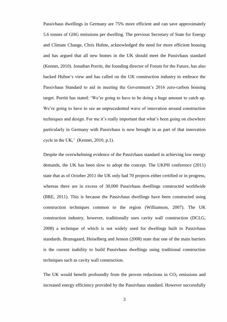
reference to external dimensions (PEP, 2006). Figure 1, shows the modelling of a
timber frame construction, with a linear thermal conductivity of 0.055 W/(mK). PEP
(2006) claim that typical values for linear thermal conductivity within Passivhaus
dwellings range from 0.03 to 0.01 W/mK. These thermal bridges are required to be
minimised in all details and not just windows and doors.
10
Figure 1. Linear thermal conductivity Ψ ≤ 0.01 W/mK
(Source: SINTEF Byggforsk, PHI, ProKlima cited in PEP, 2006).
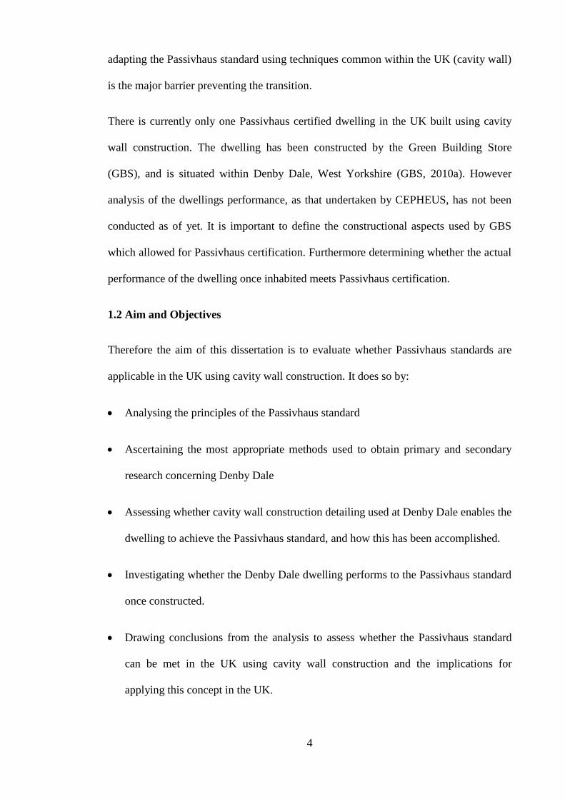
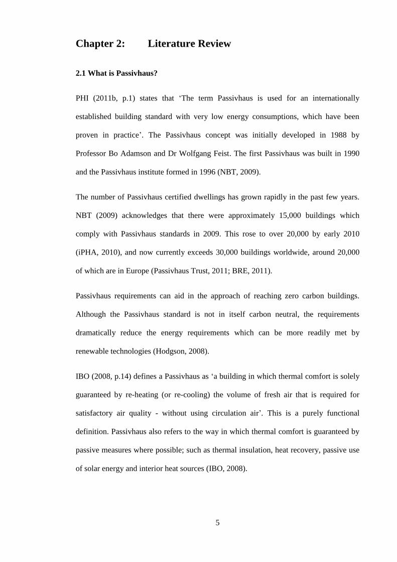
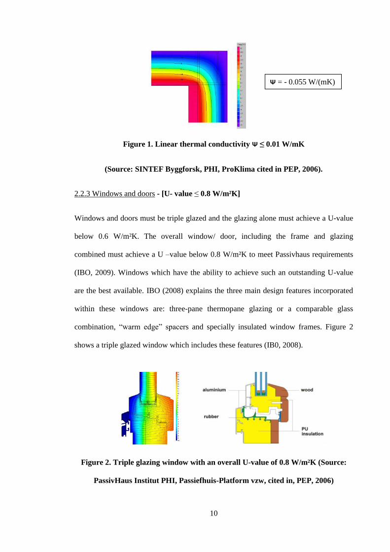
2.2.3 Windows and doors - [U- value ≤ 0.8 W/m²K]
Windows and doors must be triple glazed and the glazing alone must achieve a U-value
below 0.6 W/m²K. The overall window/ door, including the frame and glazing
combined must achieve a U –value below 0.8 W/m²K to meet Passivhaus requirements
(IBO, 2009). Windows which have the ability to achieve such an outstanding U-value
are the best available. IBO (2008) explains the three main design features incorporated
within these windows are: three-pane thermopane glazing or a comparable glass
combination, “warm edge” spacers and specially insulated window frames. Figure 2
shows a triple glazed window which includes these features (IB0, 2008).
Figure 2. Triple glazing window with an overall U-value of 0.8 W/m²K (Source:
PassivHaus Institut PHI, Passiefhuis-Platform vzw, cited in, PEP, 2006)
Ψ = - 0.055 W/(mK)

11
2.2.4 Airtightness - [0.6 ach @ 50 Pa]
Passivhaus dwellings require high levels of airtightness to reduce space heating
requirements, which also aids in preventing draughts and accumulation of moisture
which would affect buildings’ performance and lifespan. High levels of airtightness
reduce natural ventilation in Passivhaus dwellings, and therefore require some form of
ventilation system. The Passivhaus airtightness requirement is a maximum of 0.6 air
changes per hour at 50 pascals of pressure (0.6 ach @ 50 Pa) (PHI, 2011b).
PHI (2011b, p.1) states that the key principle Passivhaus dwellings use, concerning
airtightness is ‘continuous uninterrupted airtight building envelope’. Achieving this
requires use of tapes, membranes, wet plaster, and vapour membranes, to create a
continuous airtight barrier. Particular attention is required at different element
connections such as doors and windows (Hodgson, 2008; PEP, 2006).
The airtightness of a dwelling is measured using a blower door test (fan pressurisation),
usually undertaken during construction to allow any weaknesses to be rectified (Leeds
Met, 2010)
2.2.5 Mechanical ventilation with heat recovery (MVHR)
Window ventilation would be insufficient, ineffective and prevent Passivhaus
dwellings’ heating requirements from being achieved. The health and comfort of
occupants is the most important feature within Passivhaus planning and therefore a
mechanical ventilation system is required at least (Hodgson, 2008; IBO, 2008).
To meet the extremely low energy Passivhaus space heating requirements
(15kWh/(m²/a)), a heat recovery system must be incorporated within the ventilation
system, with efficiency in excess of 75% and low specific fan power (ibid). Therefore a

12
Mechanical Ventilation with Heat Recovery (MVHR) system is required to replace and
maintain the air quality at a rate of 30 m³/person/hour to ensure reasonable air quality
according to PHI (2011b). The system removes unwanted odours, moisture and carbon
dioxide, whilst providing fresh air. The heat exchanger does not mix exhaust air with
fresh air but simply exchanges the heat from exhaust air to incoming fresh air
(Hodgson, 2008).
Heat recovery efficiencies range from 75 to 95% for Passivhaus standards, with aspects
such as duct work insulation, used to optimise system performance (PEP, 2006). Any
units which have not been certified by the PHI receive an efficiency penalty of 12% on
the manufacturer’s claims, therefore making it much more difficult to achieve specific
space heating requirements of 15 kWh/(m²/a) (IBO, 2009).
2.3 Passivhaus Planning Package software (PHPP)
PHPP is an excel based software package created to assist in the design of buildings
which aim to achieve the Passivhaus standard (AECB, 2006) The PHPP has been
proved reliable, as simulation data has been compared with actual measurement data
and shown to have close correlations (AkkP5, cited in: PHI, 2011a).
According to the PHI (2011a) the PHPP requires over 2000 independent input data. The
data must be in accordance with the geometry of the building in order to obtain accurate
results. The PHPP software treats the building and mechanical equipment as one overall
system (ibid).
2.4 Most common Passivhaus construction methods
The majority of Passivhaus dwellings in Northern Germany comprise of masonry walls
with external insulation, whereas 80% of Passivhaus dwellings in Southern Germany
and Austria are timber frame construction (Williamson, 2007). The percentages for

13
construction methods for Passivhaus in Germany and Austria can be seen in Figures 3
and 4.
Williamson (2007) believes that different construction systems are used to build
Passivhaus dwellings due to traditional construction practices and vernacular
architecture varying regionally. All three systems (timber frame, concrete, and masonry
with external cladding) have been proven to achieve the Passivhaus standard. The most
widely used construction methods masonry and timber frame, are briefly discussed
below.
External cladding/masonry
Masonry constructions provide good thermal mass. Thermal mass absorbs heat from the
direct sunlight and heat ventilating around the thermal wall (Chiras, 2002). Thermal
mass is particularly effective within Passivhaus concrete floor structures. The thicker
the slab the more heat stored and the longer it will release heat into the night. Generally
the slab is 100-150mm thick with cost as limiting factor (Gollaway, 2004).
Timber
Concrete
Masonry withexternalCladding
15%
70%
15%
Timber
Concrete andmasonry80%
20%
Figure 3. Passivhaus construction
methods in Germany
(Source: GBM, 2009)
Figure 4. Passivhaus construction
methods in Austria
(Source: GBM, 2009)

14
The non-load bearing insulation cladding systems are attached externally. The
insulation is in the form of preformed sheets of foam plastics and is usually attached to
the wall with adhesives or mechanical anchors, as shown in Figure 5 (Balocco, Grazzini
and Cavalera, 2007).
Figure 5. Masonry wall with external cladding
Timber frame construction
Timber framed construction is based on the erection of load bearing timber frame
supporting the dead and live loads from upper floors, roofs and the timber frame wall
itself (Riley and Howard, 2002). Timber frame construction allows thick layers of
insulation to be incorporated within the frame without the need for large wall
thicknesses which take up floor space (NBT, 2009).
Figure 6 shows a typical wall cross section detail which meets Passivhaus standard of,
U-value ≤ 0.15 W/m²K. Three layers of 80mm thick insulation is used to reduce the
small thermal bridge through the timber stud, as well as increase the overall wall
insulation thickness.

15
Figure 6. Passivhaus wall detail timber construction
2.5 UK housing construction methods
Passivhaus dwellings primarily use construction techniques and knowledge common to
the country as in which they are built. The UK could indeed transfer proven Passivhaus
techniques and construction from Central European countries, however there are major
limitations to producing a successful outcome from this method. Kaan and Boer (2005)
state that Passivhaus dwellings differentiate from region to region because of the
contractors’ familiarity with construction methods, techniques and materials common in
each particular region. Williamson (2007) agrees and states that one large barrier to the
UK adopting the Passivhaus concept is the lack of skills and knowledge in the UK
concerning timber frame and masonry with external insulation construction methods.
Therefore if the UK is going to successfully adopt the Passivhaus standard on a wide
scale it will be necessary to use construction techniques, materials and methods
common to UK contractors and builders.
UK common construction methods
The English Housing Survey (DCLG, 2008) states that almost 65% of the housing
stock, as of 2008, was constructed using a traditional cavity wall structure. However

16
approximately 88% of the dwellings built post 1990 in the UK were constructed using
traditional cavity wall structure (ibid). Figure 7 shows the proportion of tradition cavity
wall structures compared to other techniques. It can be clearly seen that traditional
cavity wall structures have been the primary construction method post 1945 in the UK.
Figure 7. UK housing construction type by dwelling ages (Source: DCLG, 2008)
Therefore cavity wall structure is currently the most widely used and recognised
technique in the UK. Contractors and builders in the UK have skills in masonry cavity
wall construction, some knowledge and skills in timber framed construction and
virtually none in masonry wall with external cladding as mostly used in Germany and
Austria.
Traditional Cavity Wall Structure in the UK and other countries
The traditional cavity wall structure consists of an inner leaf of block work, an outer leaf
of masonry and a gap/cavity creating a separation between the leaves. The cavity is
typically fully or part filled with insulation to improve the thermal properties of the

17
wall, as shown in Figure 8 the inner leaf and external leaf connected using wall ties to
provide structural strength and stability.
Figure 8. Traditional cavity wall structure
The majority of the housing stock in Denmark also consists of a cavity wall structure
(PEP, 2006). Denmark has several barriers to overcome before Passivhaus dwellings
can widely spread across the country. Other countries such as the Benelux (Belgium,
Luxemburg and the Netherlands) also traditionally use cavity wall construction methods
and continue to do so for new dwellings (Hens, et al., 2007). Therefore adapting the
Passivhaus concept using cavity wall construction is not only relevant to the UK, but
also to countries such as Denmark and the Benelux.
2.7 Conclusion
The UK has the largest skill base when concerning cavity wall construction compared to
any other construction method. It has also been identified that other Northern European
countries such as Denmark and the Benelux have past and current cavity wall
construction methods.
However, it is not known whether this construction method can be successfully adapted
to meet Passivhaus standards. There is currently only one Passivhaus certified dwelling

18
in the UK which is constructed using a traditional cavity wall structure and Passivhaus
certified. This house was built by the Green Building Store at Denby Dale, West
Yorkshire (GBS, 2010a). To determine whether Passivhaus can be adapted in the UK
using traditional cavity wall structure, it is necessary to assess the construction
techniques and details used during the construction of Denby Dale which enabled the
dwelling to achieve the Passivhaus standard. Furthermore analysis on the dwelling
post-construction will provide more significant evidence as to whether cavity wall
construction is able to achieve Passivhaus standards occupied.
The next chapter sets out the methods which would be most appropriate to determine
the techniques used during Denby Dale construction to accomplish certification, and
whether the dwelling performs to the Passivhaus once occupied.

19
Chapter 3: Methodology
3.1 Introduction
Denby Dale has been identified as the only Passivhaus certified dwelling so far in the
UK built using cavity wall construction. Therefore to address the question ‘Can
Passivhaus standards be achieved using cavity wall construction in the UK?’, the
research undertaken in this dissertation is primarily geared towards the Passivhaus
certified Denby Dale dwelling. The research is split into two parts: secondary research
evaluating the construction methods and detailing of Denby Dale, and primary research;
the performance of Denby Dale since it has been occupied.
3.2 Secondary research
This section is devoted to the construction detailing and methods used in Denby Dale.
Most of the research gathered will be obtained from the building contractor (Green
Building Store, GBS) and will therefore be secondary research. The construction
detailing will be assessed at the following milestones within the build: foundations and
ground floor structure, walls structure, roof structure, windows and doors. Each section
will be assessed against the Passivhaus standard with the use of U-value calculations,
accompanied by CAD drawings to add clarity to construction detailing. Information will
also be presented as to the efforts made by GBS to obtain high airtightness at each
construction stage. This is necessary because the Passivhaus standard requires dwellings
to be tested for airtightness in order to obtain certification.
The Passivhaus standard quantifies a maximum airtightness in terms of air leakage
within a pressurised building. Therefore data obtained from blower door tests
undertaken at Denby Dale (by Leeds Metropolitan researchers) are also analysed in
relation to the Passivhaus standard.

20
Passivhaus requires a thermal bridge free construction to ensure heat loss is minimal
and it is therefore necessary to assess thermal bridging at Denby Dale. For the building
envelope junctions this will be done by analysing GBS documents. The windows
however are an important aspect when concerning heat loss and thermal bridging,
because of the complex junctions, and are a general weakness in all buildings. Therefore
the assessment of the windows will be an amalgamation of GBS documentation and the
use of THERM software. THERM software is commonly used by building and design
professionals and would therefore be an acceptable method for this dissertation. The
software will present the thermal bridges graphically and allow greater understanding of
the importance of minimising thermal bridging in Passivhaus dwellings.
3.3 Primary research
Denby Dale will be assessed as to whether, once occupied, it performs to the Passivhaus
standard. Passivhaus quantifies specific heating and primary energy demands to enable
certification. Primary data gathered by Leeds Metropolitan researchers for gas usage,
electricity usage (national grid), electricity usage (photovoltaics) and solar thermal hot
water readings will be analysed. These data will then be assessed in relation to the
Passivhaus standards for specific space heating and primary energy demand. The data
will also be used to ascertain the carbon dioxide emissions of the dwelling, when related
to fuel usage. This will be analysed and compared with existing dwellings, and relates
back to the problem specification with the UK’s targets to reduce carbon dioxide
emissions.
Additional data will also be obtained from Leeds Metropolitan researchers concerning
the external and internal environments at Denby Dale, which have been monitored using
an outdoor weather station and indoor Tiny Tag monitors.
21
The following Denby Dale data will be obtained concerning the internal temperature,
relative humidity and carbon dioxide levels, and the external temperature and relative
humidity
The main purpose of the internal data is to assess and compare Denby Dale’s
temperature, humidity and carbon dioxide with recommended levels. The external data
will be used to assess the relationship between external conditions and energy
consumption within the house. Furthermore the data will be used to investigate whether
the external environment affects the internal environment in the dwelling.
Primary research will also be conducted in the form of an interview with the Denby
Dale residents. This is necessary in order to obtain information on how the residents’
lifestyle may affect research data. Questions concerning energy usage such as cooking
and MVHR will be referred to within research findings where appropriate. The
interview will also ask subjective questions relating to comfort and the operational
aspect of living in the house. This is necessary because thermal comfort is an important
aspect which Passivhaus aims to achieve in each dwelling. CEPHEUS (2001) has
undertaken comprehensive research on a number of Passivhaus dwellings (built using
methods other than cavity wall) which also concerns the residents’ opinions. Therefore
a section will be devoted to compare the opinions of the Denby Dale residents to those
in the CEPHEUS project.

22
Chapter 4: Research Findings 1: Denby Dale construction
methods and detailing
4.1 Introduction
The Green Building Store (GBS) has built the first dwelling in the UK to achieve
Passivhaus certification using a cavity wall structure, situated in the small village of
Denby Dale. The dwelling is referred to as ‘Denby Dale’ throughout. The purpose of
this Chapter is to present research on how the dwelling has been constructed, and the
necessary detailing required to achieve Passivhaus certification. All the constructional
aspects of the Passivhaus standard and MVHR system researched in the Literature
Review (Chapter 2) will be compared with secondary research on the construction of
Denby Dale. The Passivhaus requirements are shown below in Table 4.
Table 4. Passivhaus requirements relating to construction fundamentals and
MVHR system (Source: IBO, 2008; PHI, 2011b)
Measure Passivhaus standard
Ground floor U-value ≤ 0.15 W/m²K
Walls U-value ≤ 0.15 W/m²K
Roof U-value ≤ 0.15 W/m²K
Window, frames and doors U-value ≤ 0.8 W/m²K
Window glazing U-value ≤ 0.6 W/m²K
Thermal bridging Ψ ≤ 0.01 W/mK*
Airtightness 0.6 ach @ 50 Pa**
Ventilation MVHR
efficiency ≥ 75%
* Ψ - linear thermal transmittance, refers to the additional heat loss (or gain) through the
building envelope per meter length of that detail.
**0.6 ach @ 50 Pa - air changes per hour at 50 pascals of pressure, measured using a
blower door test.

23
Secondary research on Denby Dale is gathered and compared to the Passivhaus standard
by the use of CAD cross sectional drawings, U-value calculations and airtightness
detailing. This research is used to assess the foundations and ground floor structure,
walls structure, roof structure and windows and doors at Denby Dale.
Information is also provided on first floor construction, airtightness detailing, and
thereafter the MVHR efficiency in relation to the Passivhaus standard. The linear
thermal transmittance relating to the thermal envelope of the building is summarised in
the conclusion. Thermal bridging at windows is an important factor because of the
major weakness concerning heat loss, this is analysed using THERM software.
4.2 Foundations and ground floor
The design and construction details of the foundations to ground floor are crucial for
Denby Dale to perform to the Passivhaus standard. GBS realise that all buildings
contain thermal bridges, and are impossible to eradicate; however any thermal bridges
present must be minimised through the design and materials used.
The Denby Dale cavity wall continues through to the concrete trench foundations
creating a thermal bridge. This thermal bridge allows heat to transfer from the interior,
down through the inner leaf of block work past the floor insulation, and conduct into the
ground. GBS (2010a) have minimised this thermal bridge by using lightweight aerated
7N/mm² Celcon block, which has a greater thermal resistance than dense concrete
blocks. Also 300mm thick polystyrene insulation (explained more in depth later)
extends to the concrete strip foundation to reduce the effect of the thermal bridge. GBS
(2010a, p.8) simply explain this as ‘so any heat lost from the concrete floor slab will
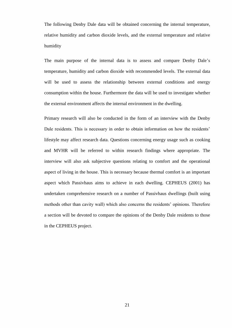
have a lot further to go’. Figure 9 shows a cross sectional view of the foundations and
ground floor for Denby Dale, details of which were obtained from GBS (2010a).
24
Figure 9. Denby Dale foundations and ground floor, cross section
4.2.1 Passivhaus U-value requirement comparison
For a dwelling to perform to the Passivhaus standard the U-values for walls, roof and
ground floor should be no greater than 0.15W/m2K (PHI, 2011b). Denby Dale will need
to achieve these heat transfer coefficients for each of the stated building elements, in
order to minimise heat loss and allow the building to achieve Passivhaus heating
requirements. As can be seen in Figure 9 the insulation is 225mm of Knauf polyfoam
and is installed below the concrete floor slab. The U-value through the ground floor has
been calculated in Table 5.

25
Table 5. Denby Dale ground floor U-value calculations and Passivhaus U-value
insulation requirements (Source: Bath, 2001; GBS, 2010b; Knauf, 2011c)
Layer Material
thickness (m)
Thermal conductivity
(W/mK)
Resistance
(m²K/W)
External Surface - - 0.06
Insulation (Knauf
Polyfoam floorboard) 0.225 0.033 6.82
Concrete Slab 0.100 1.130 0.09
Floor Screed 0.025 0.410 0.06
Internal Surface - - 0.12
Total Resistance - - 7.15
Overall U-value 0.14 W/m²K
Passivhaus
requirement ≤ 0.15 W/m²K
Table 5 reveals that the overall U-value for the entire cross section of the ground floor is
0.14W/m2K. This is below to the Passivhaus required heat transfer coefficient of
0.15W/m2K and therefore complies with the standard.
4.2.2 Airtightness detailing
It is important that airtightness is maintained throughout the build to ensure that once
completed the heat loss by convection is minimised. The steps taken at ground floor
level for airtight detailing are discussed here.
The hardcore was laid in 150mm compact layers, as would be the case for an ordinary
house, and a sand blinding to smooth and level off (GBS, 2010a). The 225mm of Knauf
polyfoam installed below the floor slab insulation has a damp proof membrane on top,
which consists of: damp proof membrane and reinforced steel mesh and spacer blocks,
with 100mm of concrete floor slab (ibid).

26
GBS (2010a) have used the polystyrene insulation as formwork to hold the concrete
whilst pouring, this enabling the floor to sit on top of the inner leaf block work. The
airtightness will therefore be improved by this measure as subsequent shrinkage and
cracking between floor and wall elements will have little effect (ibid).
Services
GBS (2010a) have ensured all drainage pipes protrude underneath the floor slab to
minimise thermal bridging. This can be seen in Figure 10, a photograph taken during
the construction of Denby Dale. Gas and electrical supply have to protrude through the
cavity, but airtightness is maintained by the use of grommets. The design has been well
thought through to enable sealing to take place around service pipes once the pipe has
been inserted.
Figure 10. Service penetration at ground floor (Source: GBS, 2010a)
Grommets
Pro Clima Rolflex and Kalflex grommets have been used for providing the airtightness
around service pipes at Denby Dale (GBS, 2010b). The grommets are designed to fit
and adhere around the service pipes covering diameters of 6mm-320mm, which are then
plastered over to prevent air leakage (GBS, 2010a; Pro Clima, 2011a; Pro Clima,
2011b).

27
4.3 Wall structure
The Denby Dale cavity wall is constructed from dense concrete block (internally),
insulation within the cavity consisting of three 100mm layers of Dri-Therm fibreglass
insulation batts, and 100mm of coarse natural stone on the outside (GBS, 2010a). GBS
(2010a) explains that the use of polystyrene solid closed-cell insulation within the
cavity below ground provides stability in the event of ground movement. Furthermore
the closed cell structure prevents the absorption of water. Insulation must be kept dry
because the presence of water reduces thermal performance by creating thermal
bridging (ibid).
The polystyrene foam is continued from the concrete trench foundation through to
above floor level. GBS (2010a) ensured the top of the solid polystyrene insulation was
cut at an angle to ensure any cavity water would run out through the porous external
cladding. This can be seen on Figure 11 which is an image taken during the construction
of the ground floor and cavity wall. This angle prevents the build up of water on the
impermeable polystyrene insulation which if allowed to occur would create a thermal
bridge.
Figure 11. Denby Dale cavity wall and cavity tray (Source: GBS, 2010d)
28
GBS (2010a) used Teplo ties instead of standard stainless steel walls ties. This is
because stainless steel wall ties act as a thermal bridge through the insulation due to
their high thermal conductivity. Wall structures with wider cavities also require longer
wall ties. Leeds Met (2010) research shows that steel wall ties can significantly increase
the overall U-value, deemed unacceptable for high performance cavity wall structures as
required in Denby Dale.
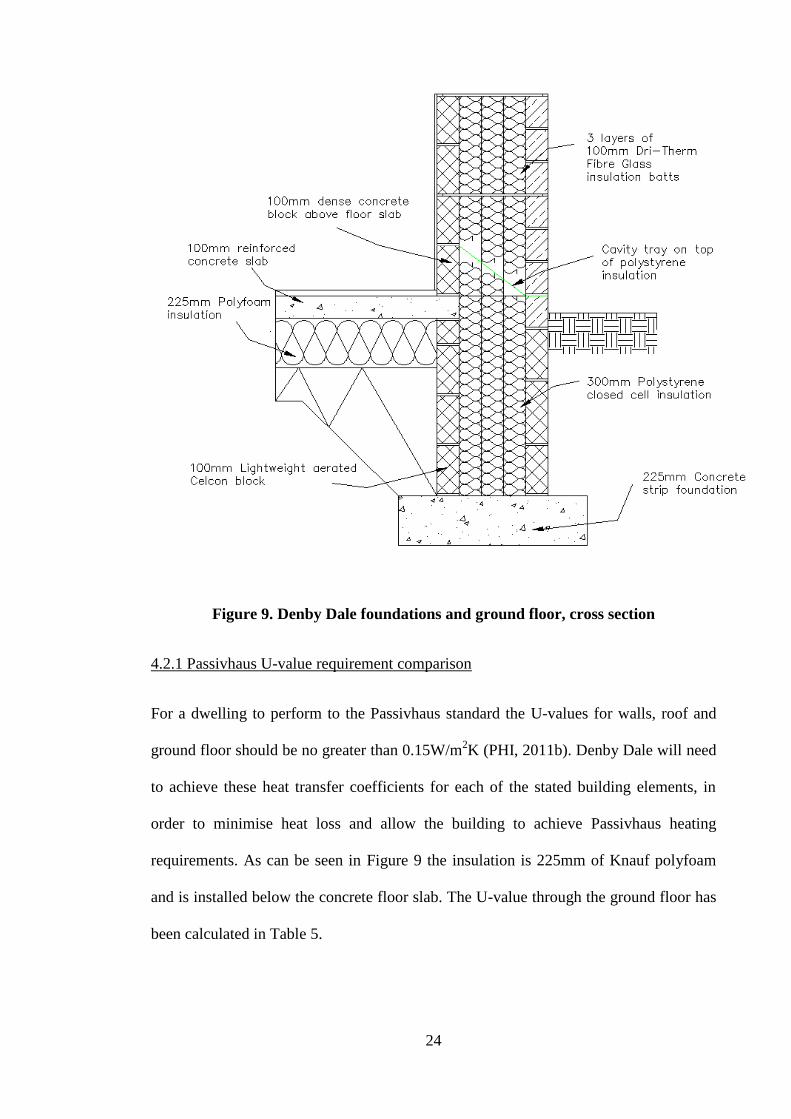
The Teplo tie consists of Basalt and resin, providing high strength and low conductivity
of 0.7 W/mK (as calculated to EN ISO 6946), each 450mm long, (GBS, 2010b). GBS
(2010a) claim that the Teplo ties’ low conductivity gives a nil value for heat transfer
within the PHPP. The Teplo ties are shown on Figure 12 and are installed in every two
courses of block work and three courses of Yorkshire stone cladding.
Figure 12. Denby Dale cavity wall

29
Fibreglass insulation had been chosen to ensure no gaps were present through the entire
cavity wall (solid insulation would be difficult to install and difficult to fit around wall
ties with no gaps). Avoiding gaps in the cavity wall prevents movement of air around,
behind or within the insulation, therefore thermal bypassing cannot occur (GBS, 2010a).
4.3.1 Passivhaus U-value requirement comparison
Table 6 shows the calculation of the U-value for the external wall.
Table 6. Denby Dale wall U-value calculations, with Passivhaus U-value insulation
requirements (Source: Clarke, Yaneske and Pinney, 1990; GBS, 2010b; Knauf,
2011a; PHI, 2011b).
Layer Thickness (m) Conductivity (W/mK) Resistance
(m²K/W)
External Surface - - 0.06
Masonry Outer leaf,
Yorkshire stone 0.1 1.5 0.067
Insulation - (Knauf
Dri Therm cavity slab
32)
0.3 0.032 9.375
Blockwork 0.1 1.22 0.082
2 coat Plaster 0.012 0.5 0.024
Internal Surface - - 0.12
Total Resistance - - 9.728
Overall U-value 0.10 W/m²K
Passivhaus
Requirement U-value ≤ 0.15 W/m²K
The overall U-value of the wall is 0.10 W/m
2K which comfortably meets the Passivhaus
requirement of ≤ 0.15 W/m2K.

30
4.3.2 Airtightness detailing
GBS acknowledged that achieving high levels of airtightness in cavity wall construction
is generally more difficult than in other construction methods. This is because masonry
walls allow movement of air through the material via diffusion. To overcome this
difficulty GBS (2010a) moved away from potentially leaky plasterboard with dot and
dab adhesive, but instead used wet plaster directly onto the blockwork. A two coat layer
of plaster was layered on all the walls, providing an airtight barrier.
4.4 Roof structure
The roof trusses within Denby Dale use ‘Bob Tail’ trusses with 500mm elements (GBS,
2010a), to maintain an insulation thickness of 500mm near the eaves and also enable the
insulation to be continuous. It is impossible to eliminate the repeating thermal bridge
created through the vertical timbers members supporting the roof trusses. GBS (2010a)
have instead minimised this thermal bridge by using slim (100x38mm) timber members.
4.4.1 Passivhaus U-value requirement comparison
To simplify the U-value calculation for the roof cross section, the timber fraction has
been omitted and the insulation is considered to be continuous. Table 7 shows the
materials through the cross section of the Denby Dale roof, with corresponding
thickness, conductivity and resistance for each. The overall U-value for the roof section
is 0.08 W/m2K which is almost a 50% reduction to meet the Passivhaus requirement of
≤ 0.15 W/m2K.

31
Table 7. Denby Dale roof U-value calculations, with Passivhaus U-value insulation
requirements (Source: Clarke, Yaneske and Pinney, 1990; GBS, 2010b; Knauf,
2011b; PHI, 2011b)
Layer Thickness (m) Conductivity
(W/mK)
Resistance
(m²K/W)
External Surface - - 0.06
Roof Tiles 0.027 0.83 0.03
Insulation (Knauf
loft roll 40) 0.50 0.04 12.5
OSB 0.018 0.15 0.12
Plasterboard (2
layers) 0.025 0.16 0.16
Plaster 0.003 0.50 0.006
Internal Surface - - 0.12
Total Resistance - - 13.0
Overall U-value 0.08 W/m²K
Passivhaus
requirement ≤ 0.15 W/m²K
4.4.2 Airtightness detailing
Once again it is important to make reference to measures taken at each stage of
construction when considering airtightness for a Passivhaus. The first floor ceiling was
constructed using 18mm OSB board, which is acknowledged to be airtight (GBS,
2010a). However the butted joints were sealed using Pro Clima tapes to create an
airtight structure. The OSB boards have sufficient strength to support the 500mm thick
mineral insulation in the roof (ibid). A service void was created using batons screwed in
through the OSB board. GBS (2010a) state that with the concern of airtightness the
fixings had to be screwed tight to ensure the baton clamps onto the OSB board closing
any ruptures. This detailing can be seen in Figure 13. GBS (2010a) did not introduce a

32
loft access door in the ceiling, as this would penetrate the OSB and create more
difficulties improving airtightness.
The junction between the wall and the OSB board, as shown in Figure 13, has been
sealed using Pro Clima Contenga tape, which is vapour resistant and able to bond to
plaster and timber (GBS, 2010b).
GBS (2010a) have found that the PHPP calculation methods do not incorporate
windtightness. However through past experience they have acknowledged the
importance of creating high levels of windtightness in order to reduce levels of thermal
bypass from air movement over and around insulation. GBS have increased
windtightness within Denby Dale by carrying out the following procedures, all these
approaches used can be seen in Figure 13:
1. GBS (2010a) used timber noggins between the underside of the timber trusses
and the top of the exterior stone walling. Constructional foam was applied
behind these noggins to prevent air movement into the enclosed roof (ibid).
2. The 9mm plywood airtight soffit board was screwed to the roof trussed before
the wall was complete and was also rebated into the back of the soffit board
(GBS, 2010a). Figure 13 shows this detail including the frame mastic used to
seal the junction between the soffit board and stonework.
3. Denby Dale uses a Pro Clima Solitex roof membrane, which is a vapour-open
airtight under slating membrane, therefore allowing vapour to escape from the
roof void but prevents air movement through (GBS, 2010a; Pro Clima, 2011c).
4. GBS (2010a) layered the Pro Clima Solitex roof membrane with some tension to
enable them to easily tape the overlaps using Pro Clima Tescon Profil. Timber
counter batons, running with the gradient of the roof were used to allow any

33
water which managed to pass through to the roof membrane, to easily run off
into the guttering (ibid).
5. As an extra measure GBS (2010a) the first roof membrane layer was taped to the
noggins which themselves were taped to the truss timbers.
6. Finally GBS (2010a) ran a layer of Pro Clima Tescon Profil on top of the
noggins along the whole length of the eaves.
Figure 13. Denby Dale roof and wall junction, cross section
4.5 Windows and doors
Windows and doors are usually weak spots in dwellings, because they break the
continuity of the thermal envelope and can create large thermal bridges (Leeds Met,
2010). ISO (2008) states that in a poorly insulated house 13% of heat losses can occur
from windows and doors. Furthermore, the proportion of heat lost through windows
and doors increase as a dwelling’s thermal insulation improves. It is therefore
paramount that a highly insulated building such as Denby Dale incorporates windows
with low Psi and U-values to reduce heat loss.

34
Denby Dale’s windows and doors are manufactured by Ecopassiv, and comprise a
timber frame with argon filled triple glazing (GBS, 2010c), shown in Figure 14. The
image shows how the frame is insulated using polyurethane to minimise heat loss (ibid).
Figure 14. Ecopassiv window (Source: GBS, 2010a)
4.5.1 Passivhaus U-value requirement comparison
Table 8 shows the heat transfer coefficients for the various parts of the window and the
Psi value for the junction at which the glazing meets the frame.
Table 8. Denby Dale window specifications in relation to Passivhaus requirements
(Source: GBS, 2010c; PHI, 2011b)
Component measures Heat transfer
coefficient Passivhaus requirement
Glazing Ug 0.55 W/m²K U – value ≤ 0.60 W/m²K
Head/ Jambs, Uf 0.90 W/m²K -
Sill Uf 0.97 W/m²K -
Glazing Psi Value Ψg 0.03 W/mK -
Triple glazed window U-value 0.75 W/m²K U – value ≤ 0.80 W/m²K
The Table shows that the performance of Ecopassiv triple glazed windows is better than
the Passivhaus requirement.
Polyurethane
frame insulation
Argon filled
triple glazing
35
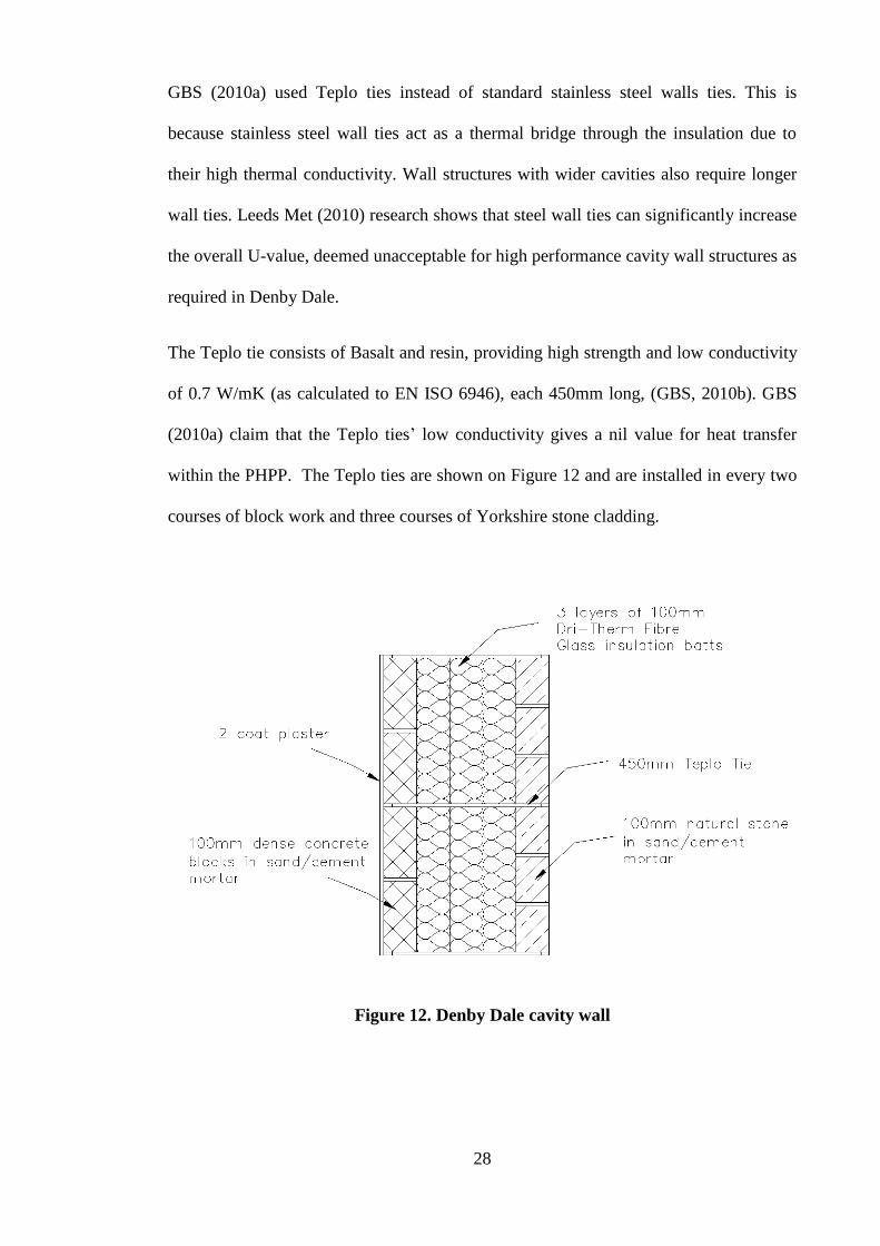
The position of the window frame in the wall is important. Research has shown (Leeds
Met, 2010) that the lowest Psi value (W/m2K) through the junction at a window frame is
achieved when the window is positioned at the central point of the cavity insulation.
Positioning the window head closer to the inner or outer leaf of the cavity wall results in
a significant increase in the Psi value and thermal bridging for the junction (ibid). As
shown at Figure 15 Denby Dale has the windows situated within the centre of the cavity
wall insulation minimising any thermal bridges at this junction.
Figure 15. Denby Dale window detailing, plan
The window frames are supported by a permanent formwork plywood box. GBS
(2010a) acknowledged that this plywood protrudes from the thermal envelope and
would therefore create a thermal bridge. It is impossible to eliminate this thermal bridge
as the window needs some form of support. To reduce the effect of the thermal bridge
GBS (2010a) ensured the plywood box only extended halfway through the cavity. This
can be seen in Figures 15 and 16. Furthermore insulation was then able to be wrapped
around the ends of the plywood box and also the window frame, again reducing areas of
thermal bridges.

36
4.5.2 Airtightness detailing
GBS (2010a) sealed the junction between the plywood box and blockwork using Pro
Clima airtightness tape. These tapes (shown in red Figures 15 and 16) are then plastered
into the blockwork creating an airtight seal. Preformed aluminium was used to close the
cavity which would otherwise expose the cavity insulation and allow unwanted air
movement through the insulation (ibid).
Figure 16. Denby Dale window detailing, cross section
4.5.3 Thermal Bridging, THERM analysis
An effective way of indentifying thermal bridging within buildings is by incorporating
CAD drawings within freely available software such as THERM and WINDOW. The

37
CAD drawings are used as an underlay, so the outline can then be recreated using
drawing tools within THERM. Figure 17 Shows a window junction within Denby Dale
drawn in the THERM (v.6) software. Each block colour represents a particular material
and corresponds to the properties of that material within the software. WINDOW (v.6)
software has been used to create the glazing which holds the corresponding data
required by THERM to complete the calculations. WINDOW software is compatible
with THERM so the Denby Dale glazing file is transferred across, and the glazing can
then located into the window frame. Boundary conditions are then assigned to the
internal and external boundaries.
Figure 17. Denby Dale window junction, isotherms produced in THERM
(Source: Author)
Figure 18 (below) shows exactly the same window junction however presented in
thermal infrared. The external and internal temperatures computed in THERM are -18˚C
and 21˚C. The 300mm thick Knauf insulation is shown to be highly effective at
preventing heat loss from the building, because Figure 18 shows the internal surface
temperature to be close to 21˚C, which is near to the internal air temperature. The triple

38
glazed argon gas Ecopossiv windows show a surface temperature exceeding 17˚C,
therefore proving successful in reducing heat loss from the building.
Figure 18. Denby Dale window junction, colour infrared produced in THERM
(Source: Author)
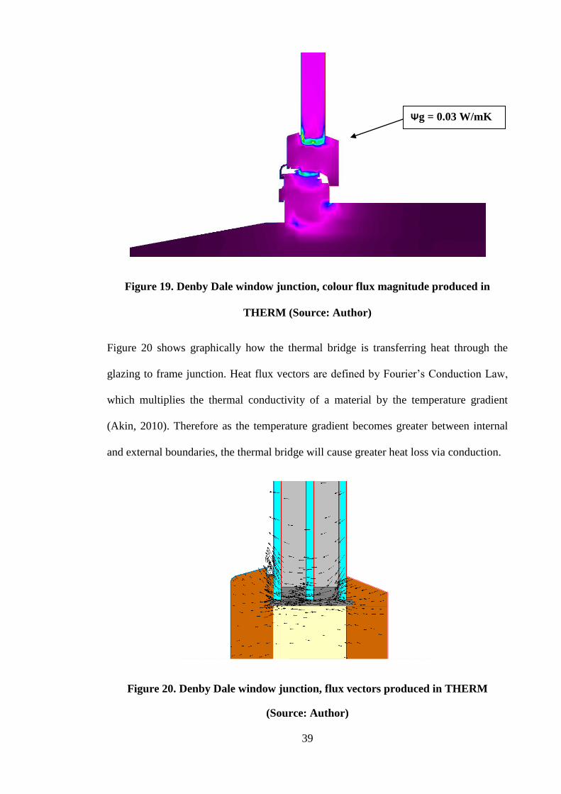
GBS (2010c) states that the glazing psi value (Ψg) in the Ecopassiv window is 0.03
W/mK, which is shown graphically in Figure 19. As typical with all windows Figure 19
shows the most significant thermal bridges occur at the glazing to frame junction and
the frame to frame junction. This is an inevitable weakness in the thermal envelope at
each of these junctions, which must be minimised as much as possible to achieve high
performance.
39
Figure 19. Denby Dale window junction, colour flux magnitude produced in
THERM (Source: Author)
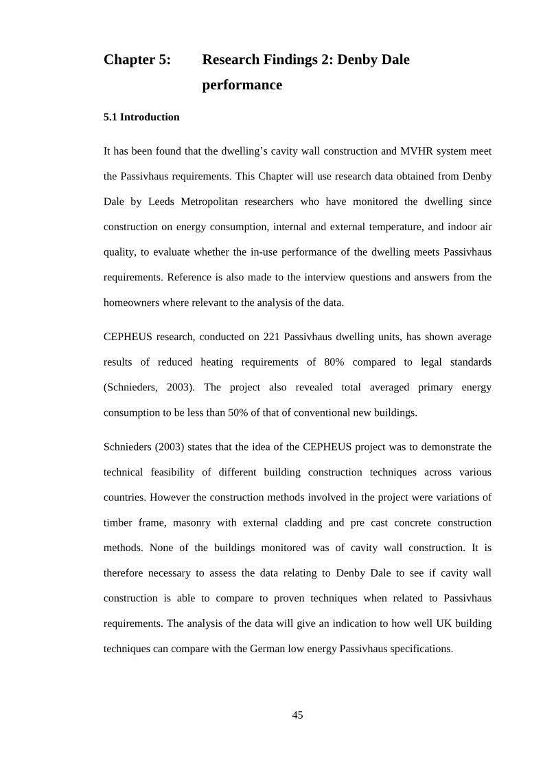
Figure 20 shows graphically how the thermal bridge is transferring heat through the
glazing to frame junction. Heat flux vectors are defined by Fourier’s Conduction Law,
which multiplies the thermal conductivity of a material by the temperature gradient
(Akin, 2010). Therefore as the temperature gradient becomes greater between internal
and external boundaries, the thermal bridge will cause greater heat loss via conduction.
Figure 20. Denby Dale window junction, flux vectors produced in THERM
(Source: Author)
Ψg = 0.03 W/mK

40
The cause of the weakness within this window, as with most other windows, is the
rubber sealant around the edge of the glazing, which creates a thermal bypass through
the frame insulation and the argon filled glazing. However the thermal bridging from
glazing to frame junctions, in this Ecopassiv window, achieve Ψg 0.03 W/mK, which is
significantly lower than standard windows. PHPP (2007) states that windows that have
Ψg 0.05 W/mK are still acceptable for use in Passivhaus dwellings. Therefore the
overall window (including U-values and thermal bridging) reduces heat loss sufficiently
to be accepted by Passivhaus.
4.6 First floor junction and airtightness detailing
Denby Dale uses a 302mm deep I-Beam system for the first floor, illustrated in Figure
21. Particular attention has been paid to the junction, where the floor meets the inner
blockwork leaf (GBS, 2010a). The I-beam floor joists do not protrude into the wall as
with usual house construction as this would lead to air leakage from the expansion and
shrinkage of the timber (ibid). Instead a 45mm/ 302mm laminated timber wall plate was
fixed to the blockwork. Prior to this the block work was parged with a sand and cement
mix to improve airtightness behind the wall plate. The wall plate was fixed using
stainless steel threaded bars with washers and nuts and taken 75mm into the 100mm
blockwork (ibid). Epoxy resin was also applied in the holes to act as a further airtight
barrier. The I-beam joists are attached to this wall plate with steel hangers. To further
improve airtightness GBS (2010a) claims to have masticked the top and bottom of the
wall plate using Pro Clima Orcon F.

41
Figure 21. Denby Dale first floor junction, cross section
4.7 Airtightness testing
In order for a house to be Passivhaus certified, an airtightness of below 0.6 ach @ 50 Pa
must be achieved. A blower door test is used to measure the airtightness of a building,
which consists of sealing a fan to an exterior door, as shown in Figure 22. Passivhaus
requires that all airtightness tests are undertaken in accordance to DIN EN 13829, which
comprises a series of over pressurization and under pressurization tests (PHPP, 2007).
The test is carried undertaken at areas of the building which involved the heated
building envelope, therefore does not include loft and garage areas.
Figure 22. Blower door airtightness test (Source: GBS, 2010a)

42
The blower door test was first undertaken on 14/01/2010, during construction, by Leeds
Met University researchers. This enabled any airtightness weaknesses to be remedied
before fully constructing the building (GBS, 2010a). The depressurisation and
pressurisation caused by the fan, forces air in and out the building, the amount of which
is measured using a DG 700 Gauge. The initial results are shown in Table 9.
Table 9. First Denby Dale blower door test results (Source: Leeds Met University)
Mean Flow @ 50Pa = 113.92 m3/h
ACH50 = 0.38 ach
Air Permeability at 50 Pa = 0.41 m/h
The air permeability is calculated from the mean flow of air at 50 Pa (the amount of air
flowing out of the building per hour, from 50Pa of pressure), which is divided by the
internal volume on the building, which is 277m3 (GBS, 2010a).
To conclude the blower door test, a smoke test was carried out to pinpoint any
vulnerable areas allowing air leakage. After GBS (2010a) rectified some of the Pro
Clima Tescon Profile tape the test was repeated and the result was an airtightness of
0.33 ach @ 50Pa, well within the Passivhaus limit of 0.6 ach @ 50 Pa.
4.8 Mechanical ventilation and heat recovery system (MVHR)
Ventilation is important in a Passivhaus dwelling to maintain internal temperatures and
supply good indoor air quality to the occupants (Passipedia, n.d).
The MVHR system installed in Denby Dale is a Paul Thermos 200 unit (GBS, 2010a),
which is shown in Figure 23.

43
Figure 23. Denby Dale MVHR system
This MVHR unit has been certified by the Passivhaus Institute (PHI) with a recorded
efficiency of 92% (Paul, 2009), with further claims that the efficiency of this MVHR
system can reach up to 94%. This is well within the Passivhaus requirement of ≥75%
efficiency.
4.9 Summary
The exterior building elements (roof, walls ground floor) have achieved overall design
heat transfer coefficients less than 0.15 W/m2K and are therefore considered acceptable
within Passivhaus standards. Passivhaus require that thermal bridges at junctions within
the thermal envelope must not exceed Ψ ≤ 0.01 W/mK, GBS (2010a) state that during
the design process with the aid of PHPP the thermal bridges in the thermal envelope
were no more than Ψ ≤ 0.01 W/mK, which is acceptable for Passivhaus.
The overall U-value for the window, which includes the glazing and the frame, is 0.75
W/m2K. This figure does not exceed 0.8 W/m
2K and therefore is within Passivhaus
requirements. The thermal bridging occurring at the windows, as demonstrated using

44
THERM software, has more leniency than thermal bridging within the thermal
envelope. GBS (2010c) states that the Ecopassiv windows achieve a glazing psi value of
(Ψg) 0.03 W/mK and installation Ψ of - 0.004 W/mK. PHPP (2007) gives examples of
psi values acceptable for windows in Passivhaus dwellings of 0.00-0.05 W/mK.
Therefore the windows used in Passivhaus dwellings would be deemed acceptable.
The blower door test shows the result of all the airtightness detailing undertaken during
each construction phase. GBS (2010a) states that the house achieved 0.33 ach @50Pa
which is better than the Passivhaus requirement by 45%.
Finally the MVHR system must have an efficiency rating of no less than 75% to be
acceptable. The Paul Thermos 200 unit achieved way in excess of this of 92% and is
therefore within the Passivhaus requirement.
45
Chapter 5: Research Findings 2: Denby Dale
performance
5.1 Introduction
It has been found that the dwelling’s cavity wall construction and MVHR system meet
the Passivhaus requirements. This Chapter will use research data obtained from Denby
Dale by Leeds Metropolitan researchers who have monitored the dwelling since
construction on energy consumption, internal and external temperature, and indoor air
quality, to evaluate whether the in-use performance of the dwelling meets Passivhaus
requirements. Reference is also made to the interview questions and answers from the
homeowners where relevant to the analysis of the data.
CEPHEUS research, conducted on 221 Passivhaus dwelling units, has shown average
results of reduced heating requirements of 80% compared to legal standards
(Schnieders, 2003). The project also revealed total averaged primary energy
consumption to be less than 50% of that of conventional new buildings.
Schnieders (2003) states that the idea of the CEPHEUS project was to demonstrate the
technical feasibility of different building construction techniques across various
countries. However the construction methods involved in the project were variations of
timber frame, masonry with external cladding and pre cast concrete construction
methods. None of the buildings monitored was of cavity wall construction. It is
therefore necessary to assess the data relating to Denby Dale to see if cavity wall
construction is able to compare to proven techniques when related to Passivhaus
requirements. The analysis of the data will give an indication to how well UK building
techniques can compare with the German low energy Passivhaus specifications.

46
Analysis is presented of the primary energy demand, carbon dioxide emissions, space
heating requirements, internal and external temperatures and humidities.
5.2 Primary energy demand
CEPHEUS (2001) states that primary energy (PE) demand consists of the sum of energy
requirements for space heating, domestic hot water and household appliances.
Passivhaus requires that the Specific Primary Energy Demand (SPED) should not
exceed 120 kWh/(m2/a), therefore it is necessary to assess energy usage data for Denby
Dale over an annual period.
Denby Dale energy consumption consists of gas usage (boiler and gas hob), and
electricity consumed (electrical appliances and lighting). Initially electricity was
provided from the national grid. However photovoltaic (PV) panels were installed in
February 2011, so the dwelling now generates its own renewable electricity as well as
exporting from the national grid. The PV panels are installed on the south-facing roof
section, as can be seen in Figure 24. Solar thermal hot water (STHW) was also
introduced to the house in March 2011, therefore the DHW demand is supplied by a
combination of STHW and gas boiler.
Figure 24. Denby Dale south elevation
47
The data has collected by Leeds Metropolitan University researchers comprises meter
readings from gas, electricity, generated electricity (PV) and STHW readings.
Table 10 shows the average annual energy usage (kWh) from, 05/01/2011 to
05/01/2012. The gas consumption for the period of 14/03/2011 to 17/04/2011 was
unrecorded because the dwelling awaited a replacement gas meter. For the purpose of
calculating PE demand for the annual period, a daily average of 6.82 kWh has been
used for this period (the consumption rate for the same period of the previous year),
value is highlighted yellow in Table 10. Table 10 shows the values of the final energy
demand (Qfinal) for Denby Dale, consisting of, gas, STHW, electricity imported and
electricity generated. The overall final energy demand for the annual period is 9366.7
kWh.
Schnieder (2003) states that research undertaken during the CEPHEUS project
concerning primary energy consumption, included only non-renewable sources of
energy to the dwellings. For example ‘energy consumption for hot water provided
directly by a solar thermal installation is not included in the final energy consumption
for the household’ (Schnieder, 2003, p347). PHPP (2007) also deducts solar thermal
energy when providing PE calculations. Therefore the renewable energy supplied by
STHW at Denby Dale is not included within the calculation. Photovoltaics are also a
non renewable energy source and are not included within this calculation.

48
Date of Reading Gas (kWh)
Electric
units
imported
(kWh)
Electricity
generated
(kWh)
STHW
(kWh)
Total Primary
Energy Usage for
the period
05/01/2011 - - - - -
02/02/2011 914.9 188.0 33.0 - 1135.9
14/03/2011 871.5 232.8 77.6 119.0 1300.9
17/04/2011 232.1 154.5 140.9 357.0 884.5
07/05/2011 51.8 77.7 99.5 270.0 499.0
25/05/2011 16.0 72.0 109.0 192.0 389.0
27/06/2011 37.2 120.9 182.6 341.0 681.7
01/08/2011 35.6 132.5 178.7 336.0 682.8
01/09/2011 22.1 131.0 129.7 345.0 627.8
01/10/2011 25.3 176.0 120.0 175.0 496.3
02/11/2011 229.6 190.2 82.1 141.0 642.9
11/12/2011 462.8 209.4 32.3 - 704.5
02/01/2012 967.5 270.6 25.9 - 1264.0
05/01/2012 67.5 0.0 0.0 - 67.5
Total annual consumption from: 5/01/2011 to 5/01/2012 Overall Final
Energy Demand
(kWh)
Final Energy Demand
(Qfinal) 3933.8 1955.6 1211.3 2276.0 9376.7
Average daily use 10.8 5.3 3.3 - 25.1
Table 10. Denby Dale annual energy usage, with Passivhaus requirement in relation to primary energy demand

49
To convert the final energy demand into primary energy demand the following formula
is used (PHPP, 2007):
QP = p ∙ Qfinal
Where:
p: non renewable primary energy factor of the energy source
Qfinal: Final energy demand
5.2.1 Comparison to Passivhaus requirement
Table 11 shows the input of Denby Dale energy consumption, primary energy factor
and the calculation from the above formula.
Table 11. Denby Dale primary energy demand calculation
Energy
Source
Primary Energy
Factor (kWh)
(PHPP, 2007)
Denby Dale Usage: 5th
Jan
2011 to 5th
Jan 2012
(kWh)
Primary Energy
Demand (kWh)
Natural gas 1.1 3933.8 4327.2
Electricity 2.7 1955.6 5280.1
Primary Energy Demand
(kWh) 9607.3
Specific PE demand
[kWh/(m2a)]
92.0
Table 11 shows the total primary energy demand to be 9607.3 kWh for the annual
period. The SPED is the PE demand per square meter of treated floor area and is 92.0
kWh/(m2a), well within the PH requirement of 120 kWh/(m
2a).
5.3 Carbon dioxide (CO2) emissions
Now that the PE demand has been determined, the GHG emissions can be calculated.
For this process all 6 greenhouse gases (CO2, CH4, HFCs, PFCs, PFCs and N2O) are to

50
be factored as CO2 equivalent emissions, related to their global warming potential
(PHPP, 2007; UNFCCC, 2008).
This is done for each energy source. The release of annual and specific CO2e emitted
can be calculated by the following formula (PHPP, 2007):
Where:
: Specific CO2 – equivalent CO2 emissions [kg/(m2a)]
: Annual CO2 – equivalent CO2 emissions [kg/a]
: CO2 equivalent emissions factor [kg/kWh]
: Energy Usage [kWh]
ATFA: Treated floor area [m2]
Denby Dale uses non-renewable sources of energy in the form of natural gas and
electricity. The PV panels and STHW do not contribute to CO2e emissions and are
therefore not included in this calculation. However the PHPP (2007) uses a PV
electricity CO2e savings factor of 0.25kg/kWh and is therefore deducted. Table 12
shows the sum of natural gas and electrical usage within Denby Dale, which is
multiplied by the CO2e emission factor ([DIN V 4701-10], [Gemis]; standard April
2004, cited in PHPP, 2007).

51
Table 12. Primary energy usage and PHPP CO2 emission factors
Energy
Source
PHPP CO2e
emission factor
(kg/kWh)
Denby Dale Usage: 5th
Jan 2011 to 5th
Jan 2012
(kWh)
Annual CO2e
emissions
(kg/a)
Natural gas 0.25 3933.8 983.5
Electricity 0.68 1955.6 1329.8
PV-electricity
(savings) 0.25 1211.3 -302.8
Annual emissions
[kg/a]: 2010.5
Specific CO2e emissions
[kg/(m2a)]
19.3
The emission factors vary according to the source and also over time periods. The SAP
(2009) carbon dioxide emission factors are used in the UK. Table 13 shows the same
calculation method but with the SAP carbon dioxide emission factors. PV electricity
CO2e emission savings factor are referred to in SAP (2009) as electricity displaced from
grid, with a figure of 0.527 kg/kWh.
Table 13. Primary energy usage and SAP CO2 emission factors
Energy
Source
SAP CO2e emission
factor (kg/kWh)
Denby Dale Usage: 5th
Jan 2011 to 5th
Jan 2012
(kWh)
Annual CO2e
emissions
(kg/a)
Natural gas 0.198 3933.8 778.9
Electricity 0.517 1955.6 1011.0
PV-electricity
(savings) 0.527 1211.3 -638.4
Annual emissions
[kg/a]: 1151.5
Specific CO2e emissions
[kg/(m2a)]
11.0
The result shows that there is a 42% difference between the specific CO2e emissions
calculated using PHPP and SAP. SAP gives lower CO2e emissions for Denby Dale
because of the lower emission factors. It is important to acknowledge both of these
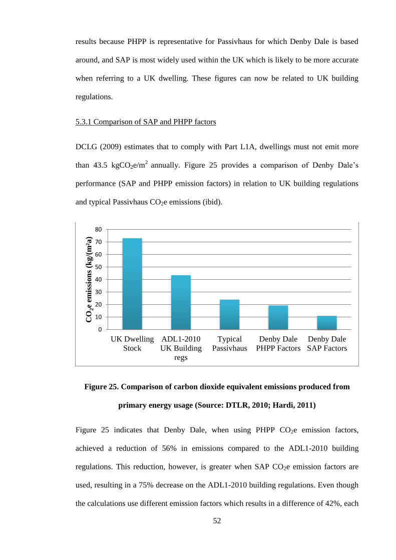
52
results because PHPP is representative for Passivhaus for which Denby Dale is based
around, and SAP is most widely used within the UK which is likely to be more accurate
when referring to a UK dwelling. These figures can now be related to UK building
regulations.
5.3.1 Comparison of SAP and PHPP factors
DCLG (2009) estimates that to comply with Part L1A, dwellings must not emit more
than 43.5 kgCO2e/m2
annually. Figure 25 provides a comparison of Denby Dale’s
performance (SAP and PHPP emission factors) in relation to UK building regulations
and typical Passivhaus CO2e emissions (ibid).
Figure 25. Comparison of carbon dioxide equivalent emissions produced from
primary energy usage (Source: DTLR, 2010; Hardi, 2011)
Figure 25 indicates that Denby Dale, when using PHPP CO2e emission factors,
achieved a reduction of 56% in emissions compared to the ADL1-2010 building
regulations. This reduction, however, is greater when SAP CO2e emission factors are
used, resulting in a 75% decrease on the ADL1-2010 building regulations. Even though
the calculations use different emission factors which results in a difference of 42%, each
0
10
20
30
40
50
60
70
80
UK Dwelling
Stock
ADL1-2010
UK Building
regs
Typical
Passivhaus
Denby Dale
PHPP Factors
Denby Dale
SAP Factors
CO
2e
emis
sion
s (k
g/(
m²a
)

53
method has shown that Denby Dale has by far exceeded the 2010 building regulations.
Figure 25 also shows that Denby Dale is performing below that of typical Passivhaus
dwellings when regarding CO2 emissions.
5.4 Space heating demand
Passivhaus dwellings require space heating energy demand to not exceed 15
kWh/(m2/a). In order to calculate the space heating requirement the heating system and
type of energy used for space heating needs to be identified. GBS (2010a) states that the
space heating system at Denby Dale is run entirely from the gas Vaillant boiler, which
is connected to the following components: as duct heater in the MVHR system (to heat
ventilation supply air), one radiator in the living room and two towel rails (also include
electric heating elements). GBS (2010a) also acknowledged that the residents may
require the towel rails to provide heating on demand to dry clothes. To resolve this GBS
installed electric heating elements within the towel rails. However the interview with
the residents, (Question 7) revealed that they did not use the electric heating elements as
the MVHR system provided sufficient heat for drying. Therefore no electricity has
contributed directly towards space heating, and is being entirely provided from the gas
boiler. The gas boiler uses energy to supply demand for domestic hot water (DHW)
which will also have to be deducted from the gas usage in order to calculate the energy
used for space heating. Furthermore the gas usage (kWh) in Table 14, will also include
gas used from the gas cooker, this will have to be deducted in order to finalise the
energy demand for space heating.
Gas used for Domestic Hot Water
The residents installed solar thermal hot water (STHW) panels on the south-facing roof
section of the house that came into operation on 3 February 2011; this information is
shown in bold in Table 14. All hot water was provided from the STHW panels from

54
20/3/11 to 13/9/11. During this period the boiler was switched off, so the amount of
energy used to supply DHW demand can be estimated from the STHW energy
generated.
Table 14. Gas energy usage and solar thermal readings, required for annual DHW
estimation (Source: Leeds Met University)
Date of
Reading
Days since
last reading Gas (kWh)
STHW
(kWh) Notes
02/02/2011 - - - -
14/03/2011 40 871.5 119.0 boiler off all MM all Hot
water from Sun
17/04/2011 34 232.1 357.0 Boiler off all dMMw All
hot water from Sun
07/05/2011 20 51.8 270.0 boiler off all MME all
hot water from Sun
25/05/2011 18 16.0 192.0 boiler off all the time
27/06/2011 33 37.2 341.0 boiler off all the time
01/08/2011 35 35.6 336.0 boiler off all the time
01/09/2011 31 22.1 345.0 Boiler off from 20.3.11
all hot water from sun
FIT 1871.8 13.9.11
01/10/2011 30 25.3 175.0 boiler off all the time
02/11/2011 32 229.6 141.0 boiler on 12-10-11
As shown in Table 14, the demand for energy to heat water in the period of 20.3.11 to
13.9.11 amounts to 1871 kWh (total of 177 days). The average daily energy used for
DWH is therefore 10.6 kWh. To determine the accuracy of the average daily gas usage
for DHW of 10.6 kWh, Figure 26 shows the average daily energy consumption and
generation. Between the period of 04/05/2011 and 04/10/2011 all hot water is provided
by STHW and therefore the daily average can be based around the STHW readings.
Figure 26 shows that a daily average of 10.6 kWh is a reasonable estimation for energy
required for DHW.

55
Figure 26. Denby Dale average daily energy consumption and generation
0
10
20
30
40
50
60
70
En
ergy i
n k
Wh
Average Daily Energy Consumption/ Generation
Mains Gas Consumed
Electricity Generated by PV
Electricity imported from grid
Solar Thermal Hot Water heat
generated
Average gas usage for DHW
approximately: 10.6 kWh

56
Therefore applying this figure to the remaining days of the year (188) gives a figure of
1992.8 kWh (from the previous 1871 kWh for 177 days). This figure can be deducted
from overall gas usage because it does not contribute towards demand for space heating.
Gas usage for Cooking
Before the specific space heating demand can be determined, the gas usage for cooking
also needs to be estimated and then deducted. Table 15 shows gas energy usage from
08/05/2011 to 01/10/2011. During this period the boiler is off all the time, because
space heating demand and DHW demand is met from alternative sources. The gas
energy usage is therefore for cooking applications (gas hob).
Table 15. Gas energy usage, solar thermal readings and boiler switched off,
required for annual gas cooking estimation (Source: Leeds Met University)
Date of
reading
Days since last
reading Gas (kWh)
STHW
(kWh) Notes
07/05/2011 - - - -
25/05/2011 18 16.0 192 boiler off all the time
27/06/2011 33 37.2 341 boiler off all the time
01/08/2011 35 35.6 336 boiler off all the time
01/09/2011 31 22.1 345 Boiler off from 20.3.11
all hot water from sun
FIT 1871.8 13.9.11
01/10/2011 30 25.3 175 Boiler off
Total 136.2
The average daily gas usage for cooking over the 147 day period is therefore 0.9 kWh.
To determine the accuracy of the average daily gas usage for cooking of 0.9 kWh,
Figure 27 shows the average daily energy consumption and generation. Between
04/05/2011 and 04/10/2011 all hot water is provided by STHW which leaves an
averaged gas used for cooking within the dwelling.

57
Figure 27. Denby Dale average daily energy consumption and generation
0
10
20
30
40
50
60
70
En
ergy i
n k
Wh
Average Daily Energy Consumption/Generation
Solar Thermal Hot Water heat
generated
Electricity Generated by PV
Electricity imported from grid
Mains Gas Consumed
Average gas usage for cooking
approximately: 0.9 kWh

58
Figure 27 shows that a daily average of 0.9 kWh is an accurate representation for
cooking gas usage. Therefore the annual estimate for cooking gas usage is 328.5 kWh.
5.4.1 Comparison to Passivhaus requirement
The space heating demand can be ascertained by deducting DHW and cooking from the
overall gas usage:
Total gas usage not specified to space heating = 328.5 + 1992.8 = 2321.3 kWh
Total annual space heating demand = 3933.3 – 2321.3 = 1612.5 kWh
Specific space heating demand = 1612.5/104.4 = 15 kWh/(m2/a)
The specific space heating demand is within the Passivhaus requirement of 15
kWh/(m2/a).
5.5 Distribution of energy use
The components which contribute to specific energy consumption can now be
identified. Figure 28 shows the breakdown of specific energy consumption.
Figure 28. Specific energy consumption
0
10
20
30
40
50
60
70
80
90
100
Denby Dale
PE
kWh
/(m
2 /a)
Cooking (Gas)
Electricity generated
Space Heating (Gas)
DHW (Solar)
Electricity imported
DHW (gas)

59
It can be seen that the energy demand for hot water has had the largest contribution to
Denby Dale’s PE consumption, approximately 44%. Space heating demand has
contributed around 21% of total PE demand, more than half of that of DHW. In
comparison to current UK housing, the DECC (2011a) states that approximately 58% of
PE consumption is used for space heating, and DHW accounts for 29%. Therefore
Denby Dale has significantly reduced requirement for space heating demand. In order to
quantify this improvement, Figure 29 shows specific PE demand for the UK dwelling
stock 2006, compared to Denby Dale PE demand.
Figure 29. Comparison of primary energy consumption: Denby Dale and UK
homes (Source: AECB, 2006)
Figure 29 shows a comparative PE performance difference of 183 kWh/(m2/a),
amounting to a 74% increased energy efficiency at Denby Dale. The most dramatic
difference can be seen with the specific space heating demand, as Denby Dale boasts a
90% improvement on the UK dwelling stock. This is largely due to the construction
detailing and an unbroken insulation layer free from thermal bridges and high level of
airtightness.
0
50
100
150
200
250
300
UK Dwelling Stock
baseline 2006
Denby Dale
PE
kW
h/(
m2/a
)
Cooking (Gas)
Electricity generated
Space Heating (Gas)
DHW (Solar)
Electricity imported
DHW (gas)

60
5.6 Indoor carbon dioxide (CO2) levels
The level of CO2 in Passivhaus dwellings is not a requirement for certification.
However high concentrations of CO2 can reduce comfort within a building and
residents’ comfort and air quality are important Passivhaus concepts. It is therefore
important to determine whether the CO2 levels at Denby Dale are at an acceptable level.
CIBSE recommends a CO2 concentration of no more than 900ppm to control human
odours and maintain comfort, and anything in excess of 1000ppm reduces human
comfort and air quality (Dearden, 2011). Assuming that outdoor CO2 levels are
approximately 400ppm, the fresh air supply rate within a home should not fall below
8l/s per adult occupant. At this rate of ventilation, the upper limit of 1000ppm CO2
concentration would not be exceeded (ibid).
CO2 levels within the Denby Dale dwelling have been measured using Tiny Tag
monitors. These monitors measure and store the data at daily intervals which can then
be downloaded onto spread sheets, all of which has been conducted by Leeds
Metropolitan Researchers. The Tiny Tag monitors have provided measured CO2 levels
in the lounge and bedroom. The results from 20/07/2010 to 06/01/2012 are shown in
Figure 30. From 28/06/2011 to 21/09/2011 there was a period of unmonitored data, due
to full data loggers. This section will therefore be assumed to follow the typical trend of
the data.
The CO2 concentrations are largely influenced by the ventilated air from the MVHR
system, and are a good indicator of how efficiently the system is working. There seems
to be an increased control of the CO2 levels throughout the time period monitored, as
differences between the lounge and bedroom are reduced. This could possibly be
explained by the residents’ response to Question 11, in the interview. The residents
admit that it took time to finely tune and adjust the MVHR system to optimise output.

61
Figure 30. Denby Dale daily average CO2 concentrations (Source: Leeds Metropolitan University)
0
200
400
600
800
1000
1200
1400
1600
1800
CO
2 C
on
cen
trati
on
in
pp
m
Daily Average CO2 Concentrations
Lounge
Bedroom

62
From the period of 20/07/2010 to 20/12/2010, when most drastic fluctuations occur, the
residents were likely to be changing the quantity of ventilated air on the settings more
frequently as they adjust the settings to their liking.
An unusual feature of the data in Figure 30 is that CO2 concentrations in the lounge are
generally higher than in the bedroom, especially between the most recent period of
20/09/2011 to 5/01/2012. Table 16 quantifies this finding, as the lounge produces a
range of 1415ppm CO2 concentration, compared to 999ppm for the bedroom. Also the
CO2 concentrations in the lounge are on average higher than in the bedroom. It is
generally found that bedrooms produce higher levels of CO2 concentrations because of
the length of time people are sleeping in these rooms (Koiv, et al., 2010). The open plan
internal layout of the building could provide a possible answer to this unusual result.
The Denby Dale first floor plan (Figure 43 in Appendices 4.0) shows that both
bedrooms are located next to the small atrium. The atrium provides a sense of open
space and also allows sunlight to filter through to the back of the building. The atrium
also allows large amounts of air movement between the bedrooms and the lounge
below. CO2 is denser than most of the other constituents of air, so the atrium could be
allowing CO2 to pass from the bedrooms on the first floor, at night, down to the lounge
on the ground floor. This would cause a decrease in bedroom CO2 readings and an
increase in lounge CO2 readings, and account for the results in Table 16.
Table 16. Denby Dale CO2 levels (ppm) from 20/07/2010 to 06/01/2012
Lounge Bedroom
Range min 240 339
Range max 1655 1339
Average 712 658
Overall Average (ppm) 685
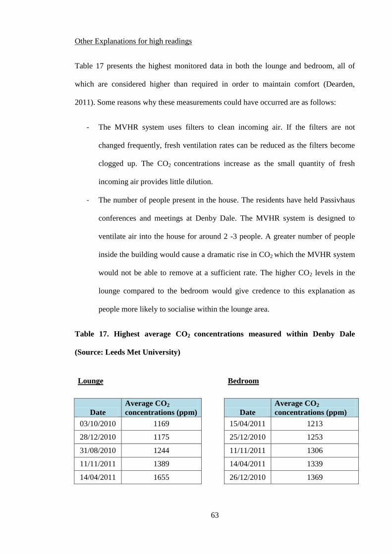
63
Other Explanations for high readings
Table 17 presents the highest monitored data in both the lounge and bedroom, all of
which are considered higher than required in order to maintain comfort (Dearden,
2011). Some reasons why these measurements could have occurred are as follows:
- The MVHR system uses filters to clean incoming air. If the filters are not
changed frequently, fresh ventilation rates can be reduced as the filters become
clogged up. The CO2 concentrations increase as the small quantity of fresh
incoming air provides little dilution.
- The number of people present in the house. The residents have held Passivhaus
conferences and meetings at Denby Dale. The MVHR system is designed to
ventilate air into the house for around 2 -3 people. A greater number of people
inside the building would cause a dramatic rise in CO2 which the MVHR system
would not be able to remove at a sufficient rate. The higher CO2 levels in the
lounge compared to the bedroom would give credence to this explanation as
people more likely to socialise within the lounge area.
Table 17. Highest average CO2 concentrations measured within Denby Dale
(Source: Leeds Met University)
Lounge
Bedroom
Date
Average CO2
concentrations (ppm) Date
Average CO2
concentrations (ppm)
03/10/2010 1169
15/04/2011 1213
28/12/2010 1175
25/12/2010 1253
31/08/2010 1244
11/11/2011 1306
11/11/2011 1389
14/04/2011 1339
14/04/2011 1655
26/12/2010 1369

64
Other Explanations for low readings
Table 18 presents the lowest monitored data in both the lounge and bedroom. Low CO2
readings are not a problem within a household; they generally mean the air quality is
better. However there must be some reason why the indoor CO2 at Denby Dale dropped
to this level.
Table 18. Lowest average CO2 concentrations measured within Denby Dale
(Source: Leeds Met University)
Lounge
Bedroom
Date
Average CO2
concentrations (ppm)
Date
Average CO2
concentrations (ppm)
08/08/2010 240 09/10/2011 275
07/08/2010 276 15/05/2011 287
29/10/2010 290 24/04/2011 298
28/10/2010 292 25/04/2011 304
27/10/2010 304 01/05/2011 314
When an interview was conducted with the Denby Dale residents (Question 11), they
stated that they opened windows whenever they feel the need to, in both summer and
winter seasons. This could explain why some CO2 readings have fallen as low as
240ppm. The majority of these low readings have occurred out of winter season, and
therefore the residents are more likely to open windows in warmer periods, creating
sudden influxes of fresh air.
However this would not explain the sub 350ppm of CO2 typical of outdoor air quality as
stated by Dearden (2011). Prill (2000) acknowledges that outdoor CO2 levels differ
from place to place due to the amount of CO2 producing activities in the areas e.g.
traffic, manufacturing etc. The Denby Dale dwelling is situated in a small West
Yorkshire village. The activities which take place in the village would be less likely
65
produce CO2 emissions than in a city. Therefore if the external air has naturally lower
CO2 concentrations, when the residents open the windows it is likely to reduce the CO2
in the dwelling.
5.7 Internal temperature
PHI (2011a) states that Passivhaus dwellings are usually maintained at around 20°C.
There is no specific internal temperature required to be met for Passivhaus certification.
However the Passivhaus philosophy states that dwellings must provide thermal comfort
for occupants. Thermal comfort and internal temperature will be assessed by analysis of
temperature readings and the residents’ own opinion.
The internal temperatures were recorded using Tiny Tag monitors placed in the kitchen,
lounge, bedroom, study and bathroom. External temperatures were recorded by a small
weather station in the garden; both of these sets of data were collected by Leeds Met
University researchers. Figure 32 shows a graph for the internal temperatures and
external temperature from the period of 20/07/2010 to 06/01/2012, which was also
compiled by Leeds Met University researchers. Also from the period of 28/06/2011 to
21/9/2011 there is unmonitored data, due to full data loggers.
As can be seen from Figure 32 the indoor temperature mostly falls within the 20°C to
25°C range. This is similar to the findings of the CEPHEUS project, as Schnieders
(2003) states that indoor temperatures within the 221 Passivhaus dwellings rarely rose
above 25°C. This observation implies that temperature within a cavity wall structure is
able to be controlled as well as dwellings built using proven Passivhaus construction
methods.
Between 20/11/2010 and 20/02/2011 there were greater fluctuations of the indoor
temperature. The bedroom temperatures are generally consistently high, almost reaching

66
29°C at one point. The kitchen area has the recorded lowest internal temperatures,
creating an average difference between bedroom and kitchen temperatures of 4-5°C.
This maybe explained from the setup of the MVHR system, because the heated supply
air is ventilated into the bedrooms, lounge and study area. Therefore when the heating
system is on during the winter period the rooms are likely to see a rise in temperature.
This corresponds to Figure 31 where the blue pipe represents the supply ducting. The
kitchen area does not receive any heated supply air but instead incorporates an
extraction duct, shown as red piping in Figure 31 representing the extraction ducts. As
the kitchen does not directly receive heated air it can therefore be expected that the
temperature would be lower than that of the bedrooms.
Figure 31. Denby Dale ventilation ducting (Source: GBS, 2010a)
Figure 32 corresponds with interview Question 11, as the residents stated that some
overheating occurred during the winter. This is unusual as the overheating has occurred
during cold winter temperatures, indicating the cause is most likely to be the heating
system. During this period the residents did not experience thermal comfort as would be
expected for a Passivhaus dwelling. However they explained that it has taken time to
adjust the settings to a comfortable temperature.

67
Figure 32. Denby Dale daily average temperatures external and internal (Source: Leeds Met University)
-10
-5
0
5
10
15
20
25
30
35
Tem
per
atu
re (
ᵒC)
Denby Dale Daily Average Temperatures
External
Kitchen
Lounge
Study
Bedroom
Bathroom

68
Post 20/02/2011 the internal temperatures in Figure 32 show more control and
consistency, mostly within the range of 21°C to 24°C. The average internal temperature
from 20/02/2011 is approximately 22°C, which the residents felt was comfortable for
their preferences as they have adjusted the MVHR system to their liking. In comparison
to the CEPHEUS project Schniders (2003) states that the mean room temperature
during the heating period was 21.4°C.
PHI (2010) states that the frequency of temperatures higher than 25˚C should occur no
more than 10% of the time. Between 20/07/2010 and 05/07/2012, 2230 daily averaged
data were monitored in the kitchen, lounge, study, bedroom and bathroom. Over this
period the daily average exceeded 25˚C on 87 occasions. This amounts to less than 4%
and therefore the dwelling has performed to the PHI recommendations.
5.8 Internal relative humidity
Relative humidity (RH) is an important factor in thermal comfort. EPA (2006) states
that as RH rises, the ability to lose heat through perspiration and evaporation reduces,
having a similar effect to raising the temperature. Extremes of RH will cause
discomfort. RH above 70% will promote the growth of mould and mildew, and levels
around 25% can cause someone to have a dry throat and nose (Lstiburek, 2002; Oozawa
et al., 2012)
A typical Passivhaus dwelling normally achieves RH levels of approximately 50% (IBO
2008). RH has been monitored at Denby Dale by the use of Tiny Tag monitors placed in
the kitchen, lounge, study, bedroom and bathroom. The external RH is measured using a
small external weather station. All this data has been collected and compiled by Leeds
Metropolitan University Researchers. Figure 33 shows the daily average RH for the
external environment and the RH for the specified Denby Dale areas.

69
Figure 33. Denby Dale daily average RH for internal and external environments
(Source: Leeds Metropolitan University)
0
20
40
60
80
100
120
Rel
ati
ve
Hu
mid
ity (
%)
Daily Average Relative Humidity
External
Kitchen
Lounge
Study
Bedroom
Bathroom

70
From 28/06/2011 to 21/9/2011 there has been a period of unmonitored data, due to full
data loggers. The purpose of analysing this data is to ascertain whether the dwelling has
performed within thermal comfort levels, and to identify the factors which affect RH.
At the start of the monitoring period, 20/07/2010 to 20/09/2010, internal RH ranged
from 60% to 75%. However soon after, the results show that the RH at between 35%
and 65% is better controlled and within a satisfactory range for health and thermal
comfort. A possible explanation for this improvement maybe due to the initial setup of
the MVHR system. The residents at have stated in the interview (Question 11) that it
has taken some time to fully adjust and optimise the MVHR settings to achieve
satisfactory comfort. It is likely that the MVHR system was providing low level of air
supply, which corroborate the observation that ‘the higher the fresh air rate, the lower
the indoor relative humidity’ (PHI, 2006, p.1).
Figure 33 shows a large observed difference between the external and internal RH. PHI
(2006) states that the MVHR system and the filters do not change the moisture content
of the external air whilst ventilated into the house, which removes the possibility that
the MVHR system could be ‘drying’ out the air. However absolute humidity in cold air
volume is much lower than that of heated air, for example 3g/m3 moisture at -5°C air
temperature is approximately 90% of humidity saturation (PHI, 2006). The same 3g/m3
of moisture at an air temperature of 20°C would only constitute to 17.6% of humidity
(ibid). Therefore as the external temperature of the air decreases so does its capacity to
hold water. The MVHR system then heats the cold air which causing the RH of the air
to drop, and resulting in low levels of RH within the house. The effect of this can be
seen in Figure 34.

71
Figure 34. Denby Dale external temperatures and internal humidity comparison
(Data source: Leeds Metropolitan University)
Figure 34 shows the close correlation of the external average temperature and the
internal humidity (lounge). Within this cold period, 05/12/2011 to 05/1/2012, the
temperature difference between external air and required internal air temperature is
between 9°C and 19°C. When the initial cold air is heated, the moisture content stays
the same, however the RH to heated air is reduced.
A simple linear regression shows the relationship between the independent (External
Temperature) and dependant (Lounge RH) variables. Figure 35 is produced from the
Denby Dale data extending from the annual period of 04/01/11 to 04/01/12, again with
the period of unmonitored data from 28/06/2011 to 21/9/2011.
The R2 value is 0.6752. This shows how much variation the relationship explains. The
nearer the R2
value is to 1 the better the ‘fit’. Wicks (1998) states that R2
values
exceeding 0.7 are regarded as high and generally means the model fits well.
0.00
10.00
20.00
30.00
40.00
50.00
60.00
External Temperature and Internal Relative Humidity
Denby Dale
Average External Temperature (°C) Lounge Relative Humidity (%)

72
Figure 35. Relationship between lounge RH and external temperature
The value of 0.6752 slightly falls below this and when multiplied by 100, gives a
confidence level of 68%. It can be concluded that there is a relationship between
external temperature and internal RH within Denby Dale. However there are other
factors which affect the results which prevent 100% confidence levels. Other factors
which could affect the internal RH could include: the presence of plants, number of
people, and activities such as showers clothes drying.
As a result of periods of low humidity one of the residents suffered from a dry throat
during the winter period (Question 14). The lowest RH reading during this winter
period was 34% on 02/01/2011, this is most likely to be the approximate date when the
resident suffered from a dry throat. A RH figure of 34% is still deemed an acceptable
level according to ASHRAE (2001) cited in (Lstiburek, 2002), as the author states that a
dry nose, throat, eyes and skin normally occur when RH is around 25% at 20°C.
However this figure is not likely to apply with everyone, as Lstiburek (2002)
R² = 0.6752
0
10
20
30
40
50
60
70
80
-5 0 5 10 15 20 25
Lou
nge
RH
(%
)
External Temperature (°C)
Linear Regression:
External Temperature and Lounge RH
73
acknowledges that people have different levels of sensitivities. In the case Denby Dale,
the resident may have a higher level of sensitivity to low levels of humidity than the
average person.
A confidence level of 68% indicates a good model fit however other sources of RH in
the dwelling such as, plants and residents in close proximity to the Tiny Tag monitors
may have reduced the confidence level of this model. A further experiment could be
undertaken to remove the possibility of other RH sources (e.g. plants and residents)
which may have caused the confidence level to decrease. The Tiny Tag monitors could
be placed near to or within the supply ductwork would reduce the Tiny Tag monitors
from picking up unwanted RH sources. Therefore the Tiny Tag monitors would monitor
RH directly concerning the supply air and would likely produce a model of increased
confidence.
5.9 Subjective assessment of maintenance, operations and comfort by occupants
Interview questions relate to any barriers the occupants encountered during the design
and construction stage, and the solutions devised to overcome them. The following
analyses the questions answered by the Denby Dale occupants in section 2.0
appendices.
Design and planning
Question 1 asks what the boundaries and requirements were during the planning phase
in order to obtain planning permission. The occupants stated that the house required to
have a coarse Yorkshire stone exterior cladding, to ensure the house followed suit with
the local area. This would of course be a requirement for any type of house being built
within the area and the fact that the dwelling is of a Passivhaus standard does not create
a limitation.

74
The occupants were able to pursue sustainable practices during the construction phase
by ensuring all materials had been locally sourced. This reducing transportation CO2
emissions during the build.
Question 2 relates to the original requirements and preferable aspects which the
occupants had to compromise in order to meet the Passivhaus requirements. The
occupants admitted that they had an open mind during the design phase of the house
because they had prior understanding and researched the importance of the design phase
to meet Passivhaus standards.
One aspect the owners had to compromise on was the size of the windows to the north
elevation. This north facing facade receives provides no solar heat gain and in effect
creates an area for heat loss. GBS did make the windows larger than initially designed,
in order to meet the homeowners requirements, and to compensate introduced higher
quality Knauf insulation to reduce heat loss through the cavity wall.
Due to the fact that GBS were able to rectify the homeowners’ concerns with larger
north facing windows, the homeowners, have answered yes to Question 3, and feel that
the house emits enough light throughout the buildings. The owners further expressed
that the large glazing to the south-west corner filters light though the length of the
dwelling which compensates for the smaller windows to the north of the house.
Question 4 then quantifies their opinion with 9/10 satisfaction for transmittance of light
into the building.
The answer to the subsequent questions shows that Passivhaus does allow for some
flexibility within the design stage to accompany peoples preferences when concerning
window dimensions.

75
Air quality, MVHR use and ventilation habits
Question 11, refers to the ventilation used in the house whether all from the MVHR
system or part natural as well. There is a myth that windows cannot be opened with
Passivhaus dwelling because of the indoor climate being controlled with a ventilation
system. This however is not true. The Denby Dale residents state that they can open
windows whenever they feel the need to. CEPHEUS (2001) found that 18% of
occupants in Passivhaus dwellings open windows, whilst the remaining 82%
exclusively use ventilation systems to exchange spent air. It can be seen that natural
ventilation is mostly due to personal preference and the MVHR system still functions
properly nonetheless (ibid).
Questions 12, 13 and 14 relate to maintenance and operational aspects of the Paul
MVHR system. The system is left to run continuously and the only maintenance
required is changing the air filters every so often. The residents also stated that the
MVHR system was very easy to use. This is not dissimilar the results found in
CEPHEUS (2001) project which states that 94% of the occupants are satisfied or very
satisfied with their ventilation system.
The residents have stated that if there was one criticism of the MVHR system, it is that
during winter ventilated air can become dry as discussed in Research Findings 2. They
were however able to rectify the problem by placing wet towels on the hand rails and
despite this remain satisfied by the MVHR system.
MVHR systems heat the air to a maximum of 50°C, any higher would result in burning
smells from dust pyrolysis (IBO, 2008). The residents have recalled no burning smells
emanating from the MVHR system, indicating that the system is working correctly and
efficiently.

76
Thermal comfort
Thermal comfort is one of the main principles of the Passivhaus standard. Thermal
comfort is difficult to quantify and measure because personal opinion is a large
contributor. Question 16 addresses the thermal comfort within Denby Dale which the
residents thought to be excellent, creating a pleasant environment. The high levels of
airtightness within the building and a fairly even temperature throughout Denby Dale
would contribute to the pleasant environment experienced by the residents. The
residents rated their overall satisfaction to the thermal environment in Denby Dale
10/10 (Question 17). The CEPHEUS (2001) project also saw similar results with 94%
satisfied residents with the indoor climate throughout the year. Furthermore little or no
temperature stratification, compared to normal houses, was felt to be highly pleasant.
5.10 Summary
The CO2e emissions are not a direct requirement for Passivhaus but are still a
significant consideration. The dwelling achieved a 56% to 75% reduction (depending on
SAP or PHPP emission factors) compared to Part L1-2010 Building Regulations. The
introduction of PV panels has contributed to a large decrease in CO2e emissions.
Internal CO2 recordings have generally indicated acceptable levels within the dwelling,
with few explainable discrepancies. The overall annual average of 685ppm is at a level
where thermal comfort can be maintained, and indicates the MVHR system is
performing effectively.
The average internal temperature of 22°C is higher than would have been computed
within PHPP during the design phase. Initial high temperature readings at the beginning
of the year were due to ongoing MVHR adjustments. The residents have stated that they

77
achieved thermal comfort once fine tuning the MVHR system, and therefore acceptable
for Passivhaus standards.
Internal RH levels tend to drop during the winter periods and have caused some
discomfort to the residents. However the residents have been able to rectify low RH
levels by drying damp towels. On the whole RH levels have been maintained at
comfortable levels between 40-70%.
Table 19 summarises the Passivhaus standards against the analysed data throughout
Chapters 4 and 5. The dwellings ability to prevent heat loss is shown to be acceptable
by the Passivhaus standard, relating the structural component U-values, overall window
and doors U-values, thermal bridging and airtightness. This has enabled the dwelling to
perform within the two main Passivhaus specifications: specific primary energy demand
(15 kWh/(m²/a)) and specific space heating requirement (92kWh/(m²/a)) as shown in
Table 19.
Table 19. Comparison of Passivhaus standards and Denby Dale’s performance
Measure Passivhaus
standard
Denby Dale
performance
Requirement
achieved?
Insulation Walls U ≤ 0.15 W/m²K 0.11 W/m²K Yes
Insulation Roof U ≤ 0.15 W/m²K 0.08 W/m²K Yes
Insulation Floor U ≤ 0.15 W/m²K 0.15 W/m²K Yes
Window, Frames
and Doors U ≤ 0.80 W/m²K 0.75W/m²K Yes
Window Glazing U ≤ 0.6 W/m²K 0.55 W/m²K Yes
Thermal Bridges Ψ ≤ 0.01 W/mK 0.01W/mK Yes
Air Tightness 0.60 ach@50Pa 0.33 ach@50Pa Yes
Ventilation MVHR efficiency ≥75% 92% Yes
Space Heating ≤ 15 kWh/(m²/a) 15 kWh/(m²/a) Yes
Annual PE ≤ 120 kWh/(m²/a) 92 kWh/(m²/a) Yes

78
Chapter 6: Conclusions
Introduction
The UK Government has set legally binding targets which require 80% reductions in
GHG emissions by 2050. The residential sector accounted for approximately 30% of the
UK’s total CO2 emissions in 2012. Which explains why reducing energy consumption
within the domestic sector has been a main priority on the Government’s agenda. The
Code for Sustainable Homes is a step taken by Government to reduce energy
consumption in this largely energy inefficient sector.
Alternatively Germany have adapted a highly energy efficient pre-construction
calculation method of developing dwellings called ‘Passivhaus’. Post-construction
research (CEPHEUS, 2001) shows that energy savings of approximately 75% have been
achieved using Passivhaus concepts in Central European countries. This reduced energy
consumption in dwellings would contribute significantly to meet Government’s
emission reduction targets for the UK domestic sector.
The majority of Passivhaus certified dwellings within Central European countries are
built using construction methods traditional to the country or region, the majority of
these being; timber frame, concrete, and masonry with external cladding. However, in
the UK cavity wall structures are traditionally used (65% of the housing stock), which
builders have knowledge of and skills relating to this type of construction. Consequently
this creates a major barrier to the UK in adopting Passivhaus standards because there is
very little research as to whether the Passivhaus standard can be achieved using cavity
wall structure.
Denby Dale is the only Passivhaus certified dwelling, built using cavity wall
construction in the UK. It has been necessary to investigate the construction detailing
79
involved at Denby Dale to determine how Passivhaus certification has been achieved
using cavity wall construction. Further analysis of data concerning energy consumption
has been required to corroborate calculated specific energy demands with Passivhaus
standards. Therefore the aim of this dissertation has been to assess whether Passivhaus
standards can be met in the UK using traditional cavity wall construction.
Passivhaus requirements
Passivhaus certification is dictated by PHPP (2007) calculations at the design stage.
Passivhaus final specific requirements are as follows; space heating demand must not
exceed 15 kWh/(m2a) and PE demand must not exceed 120 kWh/(m
2a). Passivhaus also
requires airtightness to not exceed 0.6ach @50pa. These are the main fundamentals a
dwelling must achieve (using PHPP and blower door tests) to obtain certification. For a
dwelling to meet these final requirements then Passivhaus construction fundamentals
must be met which concern heat transfer coefficients and thermal bridging. To assess
whether Passivhaus standards can be met using traditional cavity wall construction it
has been necessary to determine the construction fundamentals and energy performance
of Denby Dale.
To assess the performance of Denby Dale secondary research was sourced mostly from
GBS concerning the construction designs and techniques. Primary research, obtained
from Leeds Met researchers, concerning energy usage (gas, electricity, electricity
generated and STHW) was analysed. Further analysis was undertaken on data
concerning internal CO2 levels, RH and temperatures, and external RH and
temperatures. This data was us to assess the indoor environment, in terms of thermal
comfort, and how external factors may affect the internal environment. The interview
conducted with the residents also allowed for a subjective assessment on which to base
occupant satisfaction levels.
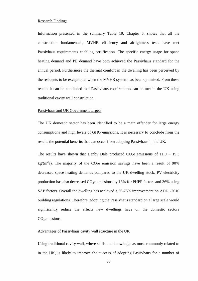
80
Research Findings
Information presented in the summary Table 19, Chapter 6, shows that all the
construction fundamentals, MVHR efficiency and airtightness tests have met
Passivhaus requirements enabling certification. The specific energy usage for space
heating demand and PE demand have both achieved the Passivhaus standard for the
annual period. Furthermore the thermal comfort in the dwelling has been perceived by
the residents to be exceptional when the MVHR system has been optimised. From these
results it can be concluded that Passivhaus requirements can be met in the UK using
traditional cavity wall construction.
Passivhaus and UK Government targets
The UK domestic sector has been identified to be a main offender for large energy
consumptions and high levels of GHG emissions. It is necessary to conclude from the
results the potential benefits that can occur from adopting Passivhaus in the UK.
The results have shown that Denby Dale produced CO2e emissions of 11.0 – 19.3
kg/(m2a). The majority of the CO2e emission savings have been a result of 90%
decreased space heating demands compared to the UK dwelling stock. PV electricity
production has also decreased CO2e emissions by 13% for PHPP factors and 36% using
SAP factors. Overall the dwelling has achieved a 56-75% improvement on ADL1-2010
building regulations. Therefore, adopting the Passivhaus standard on a large scale would
significantly reduce the affects new dwellings have on the domestic sectors
CO2emissions.
Advantages of Passivhaus cavity wall structure in the UK
Using traditional cavity wall, where skills and knowledge as most commonly related to
in the UK, is likely to improve the success of adopting Passivhaus for a number of
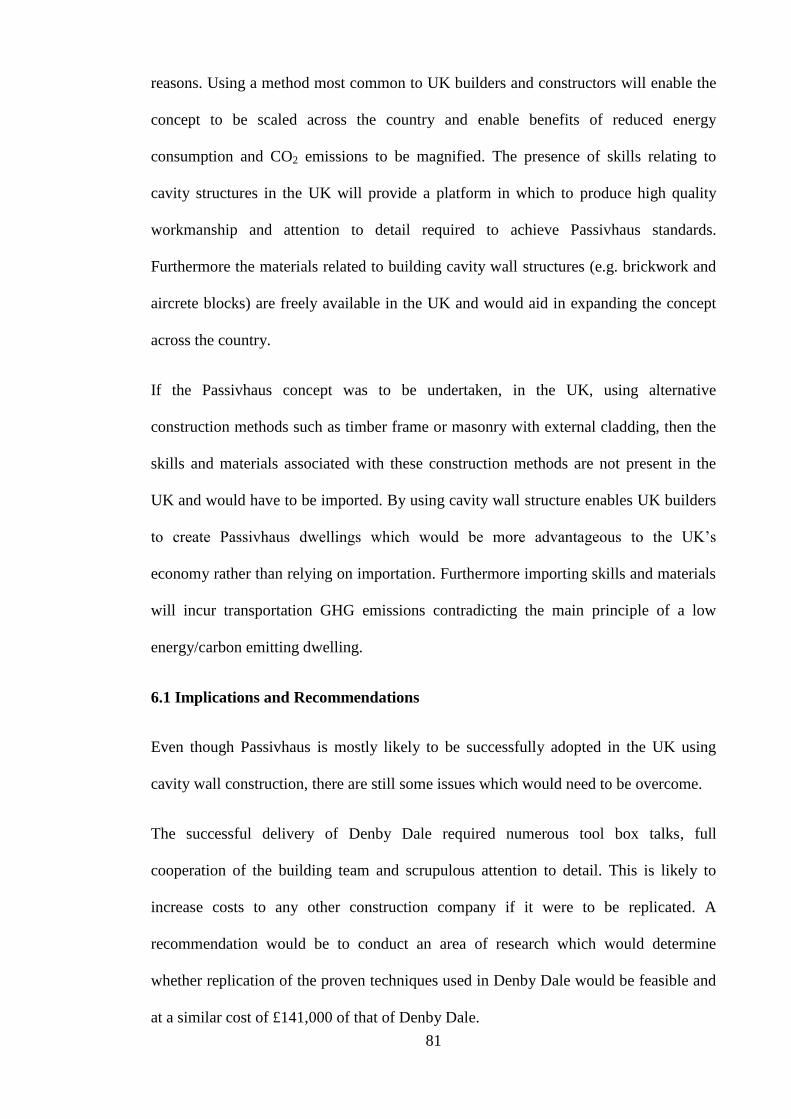
81
reasons. Using a method most common to UK builders and constructors will enable the
concept to be scaled across the country and enable benefits of reduced energy
consumption and CO2 emissions to be magnified. The presence of skills relating to
cavity structures in the UK will provide a platform in which to produce high quality
workmanship and attention to detail required to achieve Passivhaus standards.
Furthermore the materials related to building cavity wall structures (e.g. brickwork and
aircrete blocks) are freely available in the UK and would aid in expanding the concept
across the country.
If the Passivhaus concept was to be undertaken, in the UK, using alternative
construction methods such as timber frame or masonry with external cladding, then the
skills and materials associated with these construction methods are not present in the
UK and would have to be imported. By using cavity wall structure enables UK builders
to create Passivhaus dwellings which would be more advantageous to the UK’s
economy rather than relying on importation. Furthermore importing skills and materials
will incur transportation GHG emissions contradicting the main principle of a low
energy/carbon emitting dwelling.
6.1 Implications and Recommendations
Even though Passivhaus is mostly likely to be successfully adopted in the UK using
cavity wall construction, there are still some issues which would need to be overcome.
The successful delivery of Denby Dale required numerous tool box talks, full
cooperation of the building team and scrupulous attention to detail. This is likely to
increase costs to any other construction company if it were to be replicated. A
recommendation would be to conduct an area of research which would determine
whether replication of the proven techniques used in Denby Dale would be feasible and
at a similar cost of £141,000 of that of Denby Dale.

82
Airtightness in the UK housing stock is generally poor compared to other developed
countries such as Canada, Sweden and Switzerland. It is more difficult to create airtight
barriers in cavity wall structures compared to solid masonry and timber frame and is
just one example of where improved workmanship will need to be addressed.
Tradesmen will require a greater understanding of the Passivhaus concept in order to
appreciate the importance of quality workmanship and the detailing identified in this
dissertation.
A further investigation could be undertaken to determine the level of familiarity to UK
builders of cavity wall Passivhaus dwellings. UK tradesmen and builders will inevitably
have to increase understanding of the concept and finely adjust their current skills.
Conducting an interview with Denby Dale builders would gather information as to
whether cavity wall Passivhaus dwellings are a viable proposition for UK contractors.
The interview would provide direct information as to how easily UK tradesmen can
transfer their skills to construct a Passivhaus dwelling. Furthermore it will allow for
some subjective assessment to investigate whether the building skills used at Denby
Dale are easily replicable. Comparisons can then be made to German builders and UK
builders based on attitude and quality of workmanship.
If the concept is to undergo expansion then the availability of Passivhaus accredited
products would need to be increased. Triple glazing windows, for instance are not
widely available in the UK as compared to central European countries. MVHR systems
are also fundamental in Passivhaus dwellings. The Denby Dale Paul MVHR system was
imported from the German supplier and could not be sourced nationally. Other
specialist products used at Denby Dale include Teplo Ties Pro and Clima tapes and
grommets. At a holistic level, if the UK has to import Passivhaus accredited products
then transportation emissions would have a large impact and offset the dwellings low

83
CO2e emissions. It would be ideal to have UK based manufacturers for accredited
Passivhaus products to reduce this effect, this however is unlikely to happen. If future
demands where to increase for Passivhaus products then it is likely that bulk
transportation would take place and reduce GHG emissions per unit to a more
acceptable level.
Heating systems designed for lower heating demands are not widely available in the
UK. In the Denby Dale case the 4.8 kW Vaillant boiler was the lowest output boiler that
could be sourced. It is inefficient to install larger boilers than required. If the UK is to
adopt the Passivhaus standard on a large scale it would be beneficial that boilers of
smaller outputs were readily available.
Homeowners will undoubtedly have priorities and personal preferences when
concerning all aspects of a dwelling’s design. The PHPP calculation may not allow
enough scope for change to satisfy some individuals. The compromise of larger north
facing windows at Denby Dale was offset by more expensive higher quality Knauf
insulation. Therefore PHPP has provided some scope for realistic/sensible priorities in
this case. However it is likely that not everyone will be satisfied with the restrictions to
design that PHPP creates. It is therefore necessary to accept that some people will have
to compromise their original plans/needs if the dwelling is to meet Passivhaus
standards.
Overall then, although Passivhaus may be able technically to be adapted to UK
housebuilding techniques, there are still a number of constraints that could affect its
widespread uptake in the UK despite the undoubted benefits that it has been shown to
offer.

84
Bibliography
AECB (2006) Minimising CO2 Emissions from new homes. [pdf] Available at:
<http://www.aecb.net/PDFs/NewHomesCO2Savings25May06.pdf> [Accessed 29
February 2012].
AECB (2010) Something Old, Something New. [pdf] Available at:
<http://www.aecb.net/PDFs/conference10/Denby_Dale_Passivhaus_Bill_Butcher_AEC
B_2010.pdf> [Accessed 29 February 2012].
Akin, J. E. (2010) Finite element analysis concepts. Via solidworks. London: World
Scientific Publishing Co. Pte. Ltd.
Balocco, C. Grazzini, G. and Cavalera, A (2007) Transient analysis of an external
building cladding. Energy and Buildings. 40 (6), pp. 1273-1277.
Bath (2001) Thermal Properties of Building Materials. [pdf] Available at:
<http://people.bath.ac.uk/absmaw/BEnv1/properties.pdf> [Accessed 8 January 2012].
BRE (2011) What is PassivHaus? [pdf] Available at: < http://www.passivhaus.org.uk/>
[Accessed 14 December 2011].
Brunsgaard, C., Heiselberg, P. and Jenson, R. (2008) The architectural and technical
consequences of different window details in a Danish passive house. [pdf] Available at:
<http://www.vbn.aau.dk/.../The_Architectural_and_Technical_Consequences>
[Accessed 14 December 2011].
CCC (2008) Building a low-carbon economy – the UK’s contribution to tackling
climate change. London: HMSO.
CCC (2010) The Fourth Carbon Budget, Reducing emissions through the 2020s.
London: HMSO.

85
CEPHEUS (2001) CEPHEUS-Project information No. 38. [pdf] Available at:
<http://www.passiv.de/07_eng/news/CEPHEUS_final_short.pdf> [Accessed 9 January
2012].
Chiras, D. (2002) The Solar House: Passive Heating and Cooling. Canada: Chelsea
Green Publishing Company.
Clarke, J., Yaneske,P. and Pinney, A. (1990) The Harmonisation of Thermal Properties
of Building Materials. [pdf] Watford: BRE. Available at:
<http://www.esru.strath.ac.uk/Documents/89/thermop_rep.pdf> [Accessed 8 January
2012].
Climate Change Act 2008. (c.27), London: HMSO.
DCLG (2006) Code for Sustainable Homes. London: HMSO.
DCLG (2007) Building a Greener Future: Policy Statement. London: HMSO.
DCLG (2008) English Housing Survey. London: HMSO.
DCLG (2009) Proposed technical guidance for Part L. London: HMSO.
DCLG (2009) Sustainable new homes –the road to zero carbon. London: HMSO.
DCLG (2010) PPS5 Planning for the Historic Environment: Historic Environment
Planning Practice Guide. London: HMSO.
DCLG (2011) Table 101 Dwelling stock: by tenure, United Kingdom (Historical
Series). London: HMSO.
Dearden, C (2011) Ventilation and Air quality. [online] Available Through:
<http://www.bdonline.co.uk > [Accessed 12 February 2012].
DECC (2011a) The Carbon Plan: Delivering our low carbon future. London: HMSO.

86
DECC (2011b) UK climate change sustainable development indicator: 2010
greenhouse gas emissions, provisional figures and 2009 greenhouse gas emissions,
final figures by fuel type and end-user. London: Department of Energy and Climate
Change.
DECC (2011c) Energy consumption in the United Kingdom 2011. Overall energy
consumption in the UK since 1970. London: Department of Energy and Climate
Change.
DECC (2012a) Inventory Tables: UK greenhouse gas emissions. London: Department
of Energy and Climate Change.
DECC (2012b) Annual statement of emissions for 2010. London: HMSO.
DTLR (2010) The Building Regulations 2010 Approved Document, Part L:
Conservation of Fuel and Power in Dwellings. Department for transport, Local
Government and the Regions, London, HMSO.
EPA (2006) Factors Affecting indoor Air Quality. [pdf] Available at:
<http://www.epa.gov/iaq/largebldgs/pdf_files/sec_2.pdf> [Accessed 28 February 2012].
ESRL (2012) Recent Global CO2. [online] Available at:
<http://www.esrl.noaa.gov/gmd/ccgg/trends/global.html> [Accessed 21 March 2012].
GBM (2009) First Passivhaus offices to be certified in the UK [pdf] Available at:
<http://www.aecb.net/PDFs/Passivhaus_JPW_1.pdf> [Accessed 14 December 2011].
GBS (2010a) Building the Denby Dale Passivhaus, Technical Briefing.[pdf] Available
through: <http://www.greenbuildingstore.co.uk/> [Accessed 8 January 2012].
GBS (2010b) Denby Dale Passivhaus, Specification Guide. [pdf] Available at:
<http://www.greenbuildingstore.co.uk/media/page_content/Denby%20Dale/Brochure/S

87
pecification%20guide/denby%20dale%20passivhaus%20specification%20guide.pdf >
[Accessed 8 January 2012].
GBS (2010c) EcoPassiv Windows and doors. [pdf] Available at:
<http://www.greenbuildingstore.co.uk/media/page_content/Ecopassiv/Technical%20do
wnloads/Technical%20overview/ecopassiv-technical-overview.pdf> [Accessed 8
January 2012].
GBS (2010d) Denby Dale Cavity Wall and Cavity Tray. [image online] Available at:
<http://www.greenbuildingstore.co.uk/page--denby-dale-passivhaus-gallery.html>
[Accessed 11 March 2012].
GBS (2011) Ventilation (MVHR) [online] Available at:
<http://www.greenbuildingstore.co.uk/page--ventilation-mvhr.html> [Accessed 15
December 2011].
Gollaway, D (2004) Solar House, A guide for the Solar designer. Burlington: Elsevier.
Hardi, J. (2011) BRE: Building a better world. [pdf] Available at:
<http://www.ecobuild.co.uk/uploads/jennie-hardi-1.pdf> [Accessed 8 April 2012].
Hens, H., Janssens, A., Depraetere, W., Carmeliet, J. and Lecompte, J. (2007) Brick
Cavity Walls: A performance Analysis based on measurements and simulations.
Journal of Building Physics, 31(95), pp.95-124.
Hinnells, M. et al. (2007) The UK Housing Stock 2005 to 2050: Assumptions used in
scenarios and Sensitivity Analysis in UKDCM2, Report. [online] Available at:
<http://www.eci.ox.ac.uk/research/energy/downloads/bmt-ukdcm2report.pdf>
[Accessed 14 December 2011].
HM Government (2008) Climate Change Act 2008. London: The Stationery Office.

88
Hodgson, G (2008) An introduction to Passivhaus: A guide for UK application.[pdf]
Bracknell: BRE. Available through: Construction Information Service Database:
<http://www.ihs.com/en/uk/index.aspx> [Accessed 18 November 2011].
HSE (2011a) Thermal Comfort. [online] Available at:
<http://www.hse.gov.uk/temperature/thermal/> [Accessed 14 December 2011].
HSE (2011b) Thermal Comfort: 6 basic factors. [online] Available at:
<http://www.hse.gov.uk/temperature/thermal/factors.htm/> [Accessed 14 December
2011].
IBO (2008) Details for Passive Houses: A catalogue of ecologically rated
constructions. Spriner-Verlag: Austria.
IBO (2009) Details for Passive houses. 3rd
ed. Austria: Springer Wein New York.
IEA (2011) CO2 emissions from fuel combustion, highlights. Paris: International Energy
Agency.
IPCC (2007) Summary for Policy Makers In: Climate Change: The Physical Science.
Basis. Contribution of Working Group 1 to the Fourth Assessment Report of the
Intergovernmental Panel on Climate Change. Cambridge: Cambridge University Press.
ISO (2008) What is a thermal bridge. [online] Available at: <http://www.isover.com/Q-
A/Implementation/What-is-a-thermal-bridge> [Accessed 11 March 2012].
Isover (2007) Built for the future: The ISOVER Multi-Comfort House. [online]
Available at:
<http://www.isover.com/var/isover_com/storage/original/application/c7de4e9bb41b792
601df10ad2749bbf5.pdf> [Accessed 10 December 2011].

89
Kaan, H and Boer, B (2005) Passive Houses: Achievable concepts for low CO2
housing. In: ISES,The ISES Conference. Orlando, USA.
Kennet, S (2010) Huhne says all new homes should meet Passivhaus standard. [online].
Available Through: <http://www.Building.co.uk > [Accessed 12 December 2011].
Knauf (2011a) Earthwool Dri Therm Cavity Slabs. [pdf] Available at:
<http://www.knaufinsulation.co.uk/PDF/Datasheet-Earthwool-DriTherm-Cavity-Slab-
Glass.pdf> [Accessed 8 January 2012].
Knauf (2011b) Earthwool Loft Roll 40. [pdf] Available at:
<http://www.knaufinsulation.co.uk/PDF/Datasheet-Earthwool-Loft-Roll-40.pdf >
[Accessed 8 January 2012].
Knauf (2011c) Polyfoam Eco Floorboard. [pdf] Available at:
<http://www.knaufinsulation.co.uk/PDF/Datasheet-Polyfoam-ECO-Floorboard.pdf>
[Accessed 8 January 2012].
Koiv, T., Voll,H., Mikola, A., Kuusk, K. and Maivel, M. (2010) Indoor climate and
energy consumption in residential buildings in Estonian Climatic conditions. Wseas
transactions on environment and development. 4 (6), pp.235-244.
Leeds Met (2010) Virtual Site: Sustainability. [online] Available at:
<http://www.leedsmet.ac.uk/teaching/vsite/low_carbon_housing> [Accessed 7 April
2012].
Lstiburek, J. (2002) Relative Humidity. [pdf] Available at:
<http://www.buildingscience.com/documents/reports/rr-0203-relative-humidity>
[Accessed 28 February 2012].

90
NAU (2009) Thermal Comfort (Relative Humidity (RH) and Air Temperature). [pdf]
Available at:
<http://www4.nau.edu/eeop/air_quality/docs/AkIAQ_ThermalComfort.pdf> [Accessed
14 December 2011].
NBT (2009) Passivhaus, Timber Frame Systems. [pdf] Available at:
<http://www.natural-
building.co.uk/PDF/Pavatex/090216_Technical_Manual_PASSIVHAUS.pdf>
[Accessed 14 December 2011].
NHBC Foundation (2009) Zero Carbon Homes – an introductory guide for house
builders. [e-book] Bucks: NHBC Foundation. Available through: Construction
Information Service Database <http://www.ihs.com/en/uk/index.aspx>[Accessed 14
December 2011].
Oozawa, H., Kimura, H., Noda, T., Hamada, K., Morimoto, T. and Majima Y. (2012)
Effect of prehydration on nasal mucociliary clearance in low relative humidity. Auris
Nasus Larynx. 39 (1), pp.48-52.
Passipedia (n.d) Types of ventilation. [online] Available at:
<http://passipedia.passiv.de/passipedia_en/planning/building_services/ventilation/basics
/types_of_ventilation> [Accessed 11 March 2012].
Passivhaus trust (2011) Technical briefing document. [pdf] Available at:
<http://www.passivhaustrust.org.uk/UserFiles/File/Technical%20Papers/110705%20Fin
al%20PH%20ZC%20Brief.pdf> [Accessed 12 March 2012].
Passivhaus trust (n.d) What is Passivhaus. [online] Available at:
<http://www.passivhaustrust.org.uk/what_is_passivhaus.php> [Accessed 21 March
2012].

91
Paul (2009) Thermos 200/300 DC, PassivHaus compliant mechanical ventilation heat
recovery Unit. [pdf] Available at: <http://www.paul-
lueftung.net/downloads_en/thermos200-300dc_englisch.pdf> [Accessed 7 January
2012].
PEP (2006) Passive House Solutions. [online] Available at:
<http://erg.ucd.ie/pep/pdf/Passive_House_Sol_English.pdf> [Accessed 14 December
2011].
PHI (2010) What is a Passive house? [pdf] Available at:
<http://www.passivhaustagung.de/Passive_House_E/passivehouse.html> [Accessed 18
November 2011].
PHI (2011a) Passive House Institute. [online] Available at:
<http://www.passiv.de/07_eng/haupt_e.html> [Accessed 14 December 2011].
PHI (2011b) Passive House Institute. [online] Available at:
<http://www.passiv.de/07_eng/index_e.html> [Accessed 8 January 2012].
PHPP (2007) Passive House Planning Package 2007. Darmstadt: Passivhaus Institute
Pro Clima (2011a) Kaflex – Sealing Grommets for cables and small pipes 6 – 12mm.
[online] Available at: <http://www.proclima.co.nz/kaflex-sealing-grommets> [Accessed
8 January 2012].
Pro Clima (2011b) Roflex – Sealing grommets for pipes 15-320mm. [online] Available
at: <http://www.proclima.co.nz/roflex-sealing-grommets> [Accessed 8 January 2012].
Pro Clima (2011c) Solitex, High performance wall wraps and roof underlays. [pdf]
Available at: <http://www.proclima.co.nz/brochures-links-downloads> [Accessed 8
January 2012].

92
Prill, R. (2000) Why Measure Carbon Dioxide Inside Buildings? [pdf] Available at:
<http://www.energy.wsu.edu/Documents/CO2inbuildings.pdf> [Accessed 12 March
2012].
Riley, M and Howard, C (2002) House Construction: Construction Technology 1.
London: Palgrave.
SAP (2009) Technical Papers supporting SAP 2009. [pdf] Available at:
<http://www.bre.co.uk/filelibrary/SAP/2009/STP09-
B01_Changes_to_treatment_of_boilers_in_SAP_2009.pdf> [Accessed 12 March 2012].
Schnieders, J. (2003) CEPHEUS – measurement results from more than 100 dwelling
units in passive houses. [pdf] Available at:
<http://www.passiv.de/07_eng/news/CEPHEUS_ECEEE.pdf> [Accessed 9 April 2012].
State Climate Office North Carolina (2008) Atmospheric Carbon Dioxide levels and
Global temperature. [Image online] Available at: <http://www.nc-
climate.ncsu.edu/climate/climate_change> [Accessed 22 November 2011].
Stern, N., et al. (2006) Stern Review: The Economics of Climate Change. HM Treasury:
London.
Tol, R (2006) The Stern Review of the Economics of Climate Change: A comment. [pdf]
Available at: <http://ff.org/centers/csspp/pdf/20061031_tol.pdf> [Accessed 9 January
2012].
Trinick, J (2011) Passivhaus vs. the UK approach – a non-technical comparison if the
different principles. [pdf] Available at:
<http://www.aecb.net/new_releases/detail/?nId=13> [Accessed 18 November 2011].

93
UKPH Conference (2011) The UK Passivhaus Conference 2011. [online] Available at:
<http://www.ukpassivhausconference.org.uk/home> [Accessed 13 January 2012].
UNFCCC (2008) Kyoto Protocol Reference Manual: On Accounting of Emissions and
Assigned amount. [pdf] Available at:
<http://unfccc.int/resource/docs/publications/08_unfccc_kp_ref_manual.pdf> [Accessed
29 February 2012].
Wicks, M., (1998) Linear Regression [pdf] Available at:
<http://www.bren.ucsb.edu/academics/courses/206/readings/readerch8.pdf>[Accessed
29 February 2012].
Williamson, J. (2007) Passive House MSc Lecture Rev2. [e-book] Powys: Graduate
School of the Environment http. Available at:
<http//gse.cat.org.uk/downloads/passive_house.pdf> [Accessed 12 December 2011].

94
Appendices
Contents Page
1.0 Denby Dale photographs 95
2.0 Denby Dale interview questions and answers 98
3.0 Informed consent form 101
4.0 Denby Dale plans 102

95
1.0 Denby Dale photographs
Figure 36. Denby Dale south elevation
Figure 37. Denby Dale south-east elevation
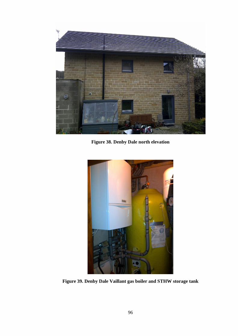
96
Figure 38. Denby Dale north elevation
Figure 39. Denby Dale Vaillant gas boiler and STHW storage tank
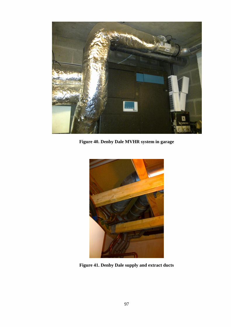
97
Figure 40. Denby Dale MVHR system in garage
Figure 41. Denby Dale supply and extract ducts

98
2.0 Denby Dale interview questions and answers
Design and Planning
1. Do you know of any requirements that had to be met in order for the plans
to obtain planning permission? E.g., was the external cladding chosen by
owners or was it a requirement?
To obtain planning permission the house had to have a coarse Yorkshire stone exterior
cladding. This was to ensure the house followed suit with the local area. The occupants
initially wanted a rendered exterior, however this had been turned down due to planning
permission.
The majority of the materials had been sourced locally to ensure small transportation
carbon emissions. This was not a requirement to obtain planning permission, but a
concept which the owners chose to carry out.
2. Did you have to change any initial designs you may have liked for your
home in order to reach the Passivhaus standard or planning permissions?
For example, did the client want more windows, or larger windows, or a
greater quantity of windows the North facing side?
The owners accepted a relatively open mind when referring to the design of the house.
This was because they acknowledged the Passivhaus standard and had prior
understanding of the importance behind the house design in order to meet PassivHaus
requirements.
The owners had initially wanted under floor heating to be included within the plans,
however this was proved not to be necessary within a Passivhaus as the internal surface
temperatures of the floors are similar to that of the air temperature.
Some of the initial plans had included very small windows to the North Elevation of the
house. However the owners preferred to have these windows made larger to create a
better view of the back garden. The GBS had rectified this, however had to comprise by
using a higher quality Knauf insulation which would lower the U-values of the building
fabric and reduce the space heating requirements calculated in the PHPP package.
3. Does the window area on the North elevation provide sufficient light?
The owners answers Yes and feel bedrooms and bathroom to the north elevation do not
require much light. Furthermore the large glazing area to the S.W corner of the house,
allows light to permeate right through the house to the lounge area and top bedroom
with balcony.
4. Overall how well does the house allow natural light to pass in? out of 10?
9/10
5. Did the house receive a Code for sustainable homes rating? If yes what was
it?

99
3
6. Has the house received a Code for sustainable homes rating after the
installation of PV cells and solar water heating?
No
Energy Usage
Two towel rails are connected to the heating system, however with little function.
Therefore electrical elements installed to provide for drying of towels when required.
7. Do you use the heating elements in the towel rails? If so how often?
The owners have never used the towel rails as the MVHR system provides sufficient
drying.
8. What type of gas cooker do you have? And how often do you use the gas
cooker per week?
NEFF electrical oven and grill, NEFF gas cooker roughly used twice a day.
9. Has the occupants changed this set temperature over the past year?
Occupants have continually adjusted the temperature to their liking, to improve thermal
comfort.
10. When was the gas heater installed in the garage?
Just a small electric heater.
Ventilation
11. Does the Mechanical ventilation with heat recovery system provide
ventilation to your liking, or do you choose to open windows within the
house?
If yes do occupants open windows in winter or summer or both?
The owners open windows whenever they feel the need to.
There was some overheating in the winter because the system had not been fully
optimised, as the occupants were in the process of adjusting the boiler in order to find a
comfortable temperature threshold.
The owners also experienced some overheating in the summer due to hot external air
being drawn in through the MVHR. The passive solar gains created from large South
glazing, caused a lot of heat storage via thermal mass. This caused overheating at night
due to the release of stored heat from the thermal mass. The owners were able to rectify
this problem by using the external blinds to reduce passive solar gains during the day
and open windows at night to remove excess heat released from thermal mass.
12. Does the MVHR require constant adjustments or is it left to run?

100
The MVHR is left to run, but have the ability to boost the ventilation if required. The
system requires the filters to be changed every so often and is the only required
maintenance.
13. Is the MVHR user friendly, easy to use?
Very easy to use
14. Have there been any problems with the MVHR, such as:
- Unpleasant burning smells
- Humidity levels, air too humid or too dry?
No burning smells
Occupants are conscious of the fact that incoming warmed fresh air is dry and also
incoming external cold air that is heated is also dry. One occasion the occupant had a
dry throat on which they rectified by placing wet towels on the hand rails.
15. Does the MVHR remove excess heat effectively? created from sources such
as: cooking stove and towel rails.
The occupants have never known the MVHR’s ability to remove heat from the house as
they have always taken advantage using natural ventilation by opening the windows to
remove excess heat.
Thermal Comfort
One of the main principles of Passivhaus is to achieve thermal comfort for habitants.
Thermal comfort “the condition of mind which expresses satisfaction with the thermal
environment”.
16. How would you describe the thermal comfort of the house?
Pleasant environment, have the advantage of being able to adjust MVHR to achieve
high thermal comfort
17. Out of 10, what is the overall satisfaction with the thermal environment
within the house?
10/10. The occupants have stated that with living in a Passivhaus has made them a lot
more aware of their energy usage.
Also extremely satisfied with lower energy bills. Denby Dale annual energy bills
amount to approximately £300.

101
3.0 Informed Consent Form
Dear .........
I am studying for a Construction Management degree at Leeds Metropolitan University.
As part of my course, I am writing a dissertation on how PassivHaus can be best
applied to new builds within the UK (please see project information sheet for more
details).
My research so far has included the technicalities involved behind the design and
construction of Denby Dale, I have obtained the majority of information from the Green
Building Store. In order to improve my research I would like to ask permission to use
data monitored within Denby Dale collected by Leeds Met researchers. The data which
I would hope use within my dissertation would be the monitoring of temperature,
energy usage, CO2 levels and humidity. I hope to use this data to assess the
performance of the building in relation to the Passivhaus standard.
I would like to conduct an interview with you focusing on energy usage within Denby
Dale and your opinion on thermal comfort within the dwelling. The interview would take
approximately 30 minutes, during which I will take notes for accuracy.
My dissertation may be made available to other students and the general public in the
university library. I will ensure your anonymity by excluding identifiable personal data
from the dissertation. However, please be aware that one of your colleagues or any
other person who knows that you have taken part in the study may be able to
recognise your input from what is said. Your participation in this study is on a voluntary
basis and you are free to withdraw from the study if you inform me.
If you have any questions about my study, I will be glad to answer them. You can reach
me on my mobile phone on 07885564866 or by email:
[email protected] You can also contact my supervisor John
Bradley for further information by e-mail [email protected].
Please sign and date the statement below if you are willing to participate. Many thanks
for your interest in my research,
Yours sincerely,
Michael Corran
Consent agreement
I, , have read the above statement and understand its
contents. I have been given the opportunity to ask questions and discuss any
concerns. I agree to participate in the study as it has been explained. I understand that
extracts of the interview may be used, in anonymous form, in the student’s dissertation.
However I understand also that my identity will not be disclosed by the researcher or
the University.
Name . Date .
PLEASE RETURN SIGNED COPY TO THE STUDENT, AND RETAIN A COPY FOR
YOUR OWN RECORDS

102
4.0 Denby Dale plans
Figure 42. Denby Dale ground floor, plan (Source: GBS)

103
Figure 43. Denby Dale first floor, plan (Source: GBS)

104
Figure 44. Denby Dale north elevation (Source: GBS)

105
Figure 45. Denby Dale east elevation (Source: GBS)
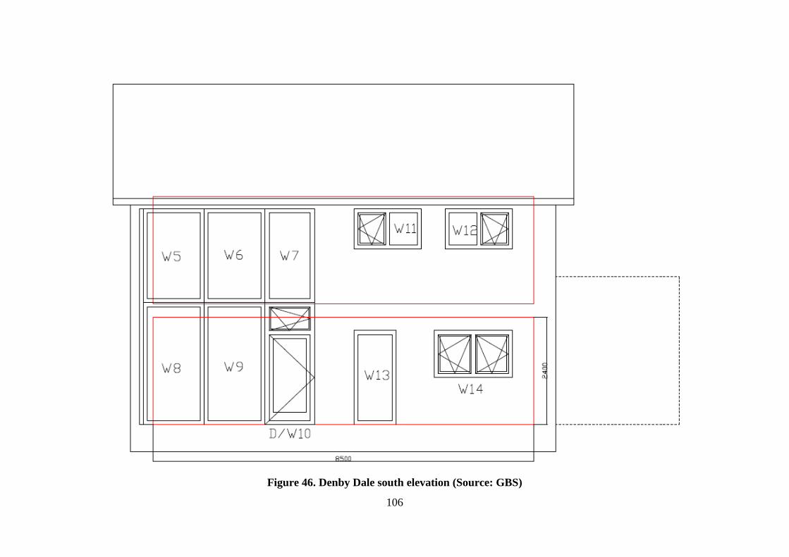
106
Figure 46. Denby Dale south elevation (Source: GBS)

107
Figure 47. Denby Dale west elevation (Source: GBS)