cambridge massachusetts - ibiblio.org system status report rev 23... · cambridge 39, massachusetts...
TRANSCRIPT

c
E-1142 (Rev. 23)
(UNC LASS1 FI ED TIT LE )
SYSTEM STATUS REPORT \ , d / ’
CAMBRIDGE 39, MASSACHUSETTS I

ACKNOWLEDGMENT
This r e p o r t w a s p r e p a r e d under DSR P r o j e c t 55-191,
sponsored by the Manned Spacecraf t Cen te r of the National
Aeronaut ics and Space Adminis t ra t ion through Cont rac t
NAS 9-153.
n This document a t ion affecting
the national defe ted S ta tes within
the meaning of the Laws, Ti t le 18,
U. S. C . , Sect i
o r the revelat ion of wh
unauthorized p
.
.
The publication of t h i s r e p o r t does not const i tute
approval by the National Aeronaut ics and Space Adminis t ra t ion
of the findings o r t he conclusions contained t h e r e i n .
published only f o r the exchange and s t imula t ion of i deas .
I t is

.
.
a
LIST. OF EFFECTIVE PAGES
Page Numbers
Title Page through vi
1-1
2-1 through 2-10
3-1 through 3-7
4-1 thrmgh 4-5
5-1 through 5-8
Distribution List
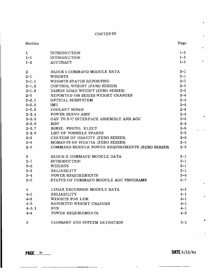
. COKTENTS
Section
1 1-1 1-2
2 2-1 2-1.1 2-1.2 2-1.3 2-2 2-2.1 2-2.2 2-2.3 2-2.4 2-2.5 2-2.6 2-2.7 2-2.8 2-3 2-4 2-5
3 3-1 3-2 3 -3 3-4 3-5
4 4- 1 4-2 4-3 4-3.1 4-4
5
INTROD C TION INTRODUC TlON ACCURACY
BLOCK I COMMAND MODULE DATA WE I GHTS WEIGHTS STATUS REPORTING CON I'ROL WEIGHT (ZERO SERlES) DESIGN LOAD WEIGHT (ZERO SERIES) REPORTED 100 SEFiIES WEIGHT CHANGES OPTICAL SUBSYSTEM IMU COOLANT HOSES POWER SERVO ASSY G&N TO S/C INTERFACE ASSEMBLY AND AGC MDV HORlZ. PHOTO. ELECT LIST OF POSSIBLE SPARES CENTERS OF GRAVITY (ZERO SERTES) MOMENTS O F lNERTIA (ZERO SERIES) COMMAND MODULE POWER REQUIREMENTS (ZERO SERIES)
BLOCK I1 COMMAND MODULE DATA INTRODUCTION WElGHTS RELIABILITY POWER REQUIREMENTS STATUS O F COMMAND MODULE AGC PROGRAMS
LUNAR EXCURSION MODULE DATA RE LIAB JLITY WEIGHTS FOR LEM REPORTED WEIGHT CHANGES N VB POWER REQUIREMENTS
GL0SSAR.Y AND SYSTEM DEFINITION
PAGF iv
Page
1-1 1-1 1-1
2-1 2-1 2-1 2-1 2-1 2-4 2-4 2 -4 2-4 2-4 1
2-4 2-4 2-5 2-5 2-5 2-5 2-5
. -
3-1 3-1 3-1 3-1 3 -4 3-7
4-1 4-1 4-1 4-1 4-1 4-3
+

ILLUSTRATIONS
. Figure
2-1
3-1
4-1
Table
2-1
2 -11
2 -111
2 -1v
3 -I
3-11
3 -111
3-IV
4-1
4-11
4-111
Electriqal Load on Primary +28 VDC Power Supply of Block I (Zero Series) Systems
Electriqal Load on Primary +28 VDC Power Supply
Electrical Load on Primary +28 VDC Power Supply
TABLES
Page
2-8
3-5
4-4
Page
Current Weight Status o Block I ( DO Series) Command Module 2-2
Block I (Zero Series) Command Module Center of Gravity and Moment of Inertia Data 2-6
Nominal Power Dissipation (watts) vs G&N Activity for Block I (Zero Series) Systems 2 -9
Block I (Zero Series) Command Module Power Profile for 14-Day Lunar Orbit Mission 2-10
Current Weight Status of Block I1 Command Module
Reliability (as of 8/15/64) 3-1
3 -2
Block I1 Command Module Power Profile for 14-Day Lunar Or bit Miss ion 3-6
Current Memory Estimates and the Status of Command Module AGC Programs 3-7
Reliability (as of 8/15/64) 4-1
Estimated Weights of LEM C&N Components 4-2
LEM Power Profile Based on LEM ICD LIS-390-3 4-5

ABSTRACT
The System Status Report is distributed monthly on the 15th. This moqth's
revision of E-1142 (Rev. 23) contains, in general, the following information for the
Block I (100 series) and Block I1 Command Module and LEM equipment configurations:
weights, centers of gravity, moments of inertia, power requirements, status of com-
puter programs, and reliability figures.

.
Section 1
ZNTRODLTCTION
1-1 INTRODUCTION
The definition of what constitutes Block I (100 series) and Block I1 Command Module and LEM hardware is contained in the Glossary, section 5 of this report.
The following information is included in this month's report:
(I) Command Module, Block I (100 series): weights. Also included for ref- erence are the following Block I (0 series) parameters: centers of gravity, moments of inertia, and power requirements.
(2) Command Module, Block 11: weights, power requirements, status of com- puter programs, and reliability figures.
(3) LEM: weights , power requirements, and reliability figures.
1-2 ACCURACY
The accuracy of numerical values reported in this revision should not be con- sidered to be within the tolerances implied by the significant figures quoted. The reported values, although based upon the most current information, a r e subject to normal changes as design and development phases approach completion.
.
.
D A T W P A G U

BLOCK I COMMAND M O D U L E
.
.
Seetl'cm 2
BLOCK I COMMAND MODULE DATA
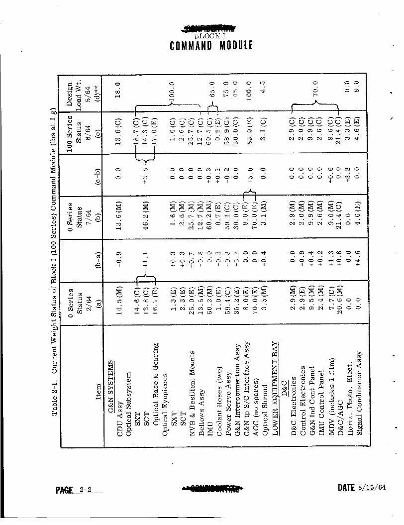
2-1 WEIGHTS
Table 2-1 presents the weights of all Block I flight systems (100 series sys- tems) equipment, grouped according to specific location within the Command Mod- ule. Weights are reported to the component level and to the nearest tenth of a pound.
Given component weights are identified as estimated, calculated, and measured in the order of increasing accuracy. These terms a r e defined by North American Aviation as follows.
Estimated weights (E) a r e based on rough calculations. Calculated weights (C) are based on detailed calculations made from final production drawings that will be used to build flyable equipment. Measured weights (M) are the actual weights of equip- ment built to the production drawings.
North American Aviation will provide and be responsible for cold plate weights that are not integral with guidance and navigation equipment.
2-1.1 WEIGHTS STATUS REPORTING. Table 2-1 also offers a comparison of pre- sent 100 series component weight values w-ith the zero ser ies components listed in System Status Report, E-1142 (Rev. 22) July 15, 1964. All weight changes are ex- plained in paragraph 2-2.
2-1.2 CONTROL WEIGHT (ZERO SERIES). ruary 15, 1964 weight status of Apollo G&N zerc series equipment. up to approximately the total control weight specified in letter PG-64-113 (March 6, 1964) from Mr. D. Gilbert, ASPO, to Mr . M. Trageser, MIT/IL.
Column (a) in Table 2-1 contains the Feb- Column (a) adds
2-1.3 DESIGN LOAD WEIGHT (ZERO SERIES). At NASA Coordination Meeting No. 15A, MIT agreed to assign "not-to-exceed" design load weights for individual Block I G&N zero ser ies sybsystems. These weights were assigned by MIT in MIT letter AG 594-64, 18 May 1964, and are shown in column (d) of Table 2-1. The total design load weight represents a secure maximum, since it is unlikely that the largest increases in each subsystem will occur simultaneously. The design loads listed recognize possible individual increases to account for changes accepted by NASA for the 100 series systems.
DATEA,&L!.G~. P A G E .
cl rn
c d
I e
C O M M A N D M O D U L E
0 0 " "
0 0 a 0 0 0 m 0
co O iin 1 0 0 + 0 0 0 0 d 0 co b T P 0
" " a
L-
0 0 0 0 wocr30 0 m 0 0 0 0 0 0 0 0 m 0 0 0 0 0 o o m o
. . . . . . . . o o o o m d c \ 1 3 0 0 . I " . " " . 0 co
+ + + + I- I t
O Q ) * N m c o o w
I + + + + + . . . . m m mom ma1 o o +
I + + + + 1 I I I I
. . e . . r O . " .
Q) d
0 t-l 0 0 ~ 0 0 0 0 ~ 0 0 0 0 0 0 0 d O O *

.
- C O M M A N D M O D U L E
BLOCK I
o o o m " l " .
0
W C ' ) L O O % I hl
h h h h
5.2 u,
m m o w r l c . 1 0 4 . . . .
Q,
0 + O d W r l
O O M O + I I
e . . s
m * W b m 0 l - l h l m r i hl
. . . .

COMMAND MODULE
2-2 REPORTED 100 SERIES WEIGHT CHAXGES
The weight changes shown ir+ cdumn (c-k) of Table 2-1 a r e explained below. changes represent the differences betw wi t.he current zero series and 100 ser ies sys- tems weight estimates. The identification of the 100 series systems (previously called Block IF) is the result of a ser ies of modifications to the basic zero ser ies systems. These modifications were approved by NASA (Ref: MSC TWX No. E G04-17-64-208).
These
J
2-2.1 OPTICAL SUBSYSTEM ( t 3 . 8 lb s ) . corporated into the 100 ser ies systems. This subsystem contains the horizon photo- meter and star tracker.
The Block 11 Optical Subsystem has been in-
2-2.2 IMU (+O. 3 lbs). Three friction vibration dampers have been added, one to each of the one-speed axis ends. to eliminate high vibration magnification (+O. 1 lbs). Insu- lation has been added to the IMIl heat exchanger area only (0.2 lbs).
2-2.3 COOLANT HOSES (+O. 1 lb}. strength and manufacturabil i ty .
The aluminum flex hoses were changed to steel for
2-2.4 POWER SERVO ASSY (-0.2 Ibs). increased stiffness and for better thermhl contact with the cold plate (-2.3).
The toe plate has been changed to beryllium for
Ten plastic covers, gaskets, and mounting screws have been added to each tray of the PSA for moisture proofing (to. 5 lbs).
Additional electronics have heen added to trays 8, 9, and 10 as a result of the following changes (-to. 8 lbs):
(1) Optics changes for compatability with star tracker and horizon photometer, (2) com- ponent value change in 2-speed switch, (3) component value change in compensation mod- ule, (4) change to new motor drive amplifiers with SCT rate feed forward, and (5) change to relay module.
A module has been added to tray 10 for phot,ometer peak and amplifier/star presence (+O. 77 lbs). - 2-2.5 G&N TO S/C INTERFACE ASSEMBLY AND AGC (+5.0 lbs). A different thermal con- figuration requires a heavier case, corporation of the AGC end connector into the case and by the elimination of the toe cap.
2-2. 6 MDV (0 .6 lbs). ements from moisture (+O. 4 lbs) and t h e MDV frame has been strengthened (+O. 2 lbs).
This weight. increase will be partially offset by the in-
Sealed coveys have beell added to protect the electric and optical el-

BLOCK I
C O M M A N D M O D U L E
2-2.7 HORIZ. PHOTO. ELECT. (+3 .3 lbs). Additional horizon photometer and star tracker electronics will be located on an auxiliary header attached to the right-hand wall behind the MDV.
2-2.8 LIST O F POSSIBLE SPARES. The need for spares has been eliminated.
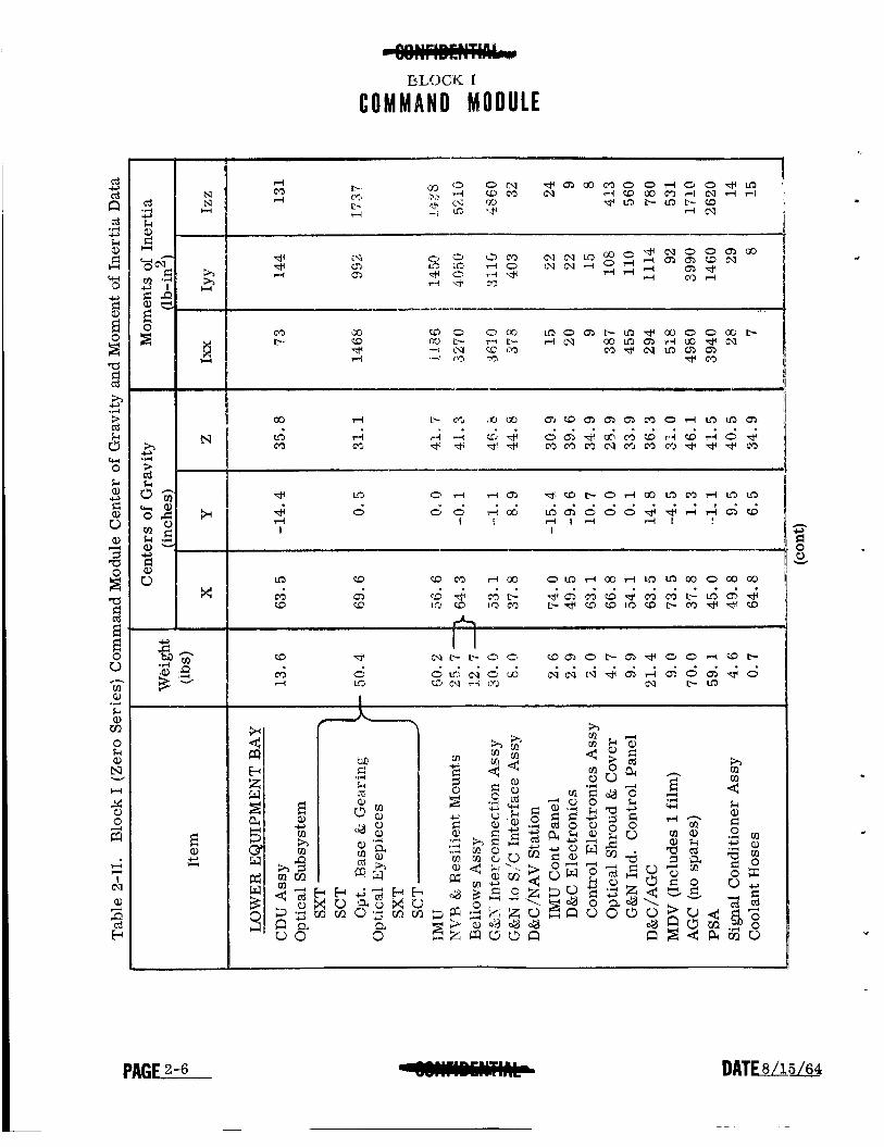
2-3 CENTERS O F GRAVITY (ZERO SERIES)
Table 2-11 presents the centers of gravity of each zero ser ies weight component o r packaged assembly, determined with respect to the basic X, Y, Z axes of the Com- mand Module. Center of gravity values are given to the nearest tenth of an inch.
2-4 MOMENTS OF DERTT-4 (ZEECI SERIES)
Table 2-11 also presents the moment of the inertia of each zero ser ies weight component o r packaged assembly. determined about each of the component axes which (1) run through the center of gravity of the component and (2) are parallel to the basic X, Y, Z axes of the Command Module. The total center of gravity and moments of inertia of all G&N equipment (excluding loose stored items) have been cal- culated about the basic x, Y , Z axes also.
2-5 COMMAND MODULE POWER REQUIREMENTS (ZERO SERIES)
The power requirements of the Command Module G&N zero ser ies equipment on the primary +28 VDC power supply are shown in figure 2-1, which presents the mag- nitude and location of dissipated power values on a subassembly level. This chart as- sumes a 14-day lunar mission as defined by SgtID for power profile computation (Ref: S&ID letter 63 MA 7332).
Table 2-111 shows the magnitude and location of power dissipation for the estab- lished G&N activities, each of which consists of various power levels of operation.
c
c
Table 2-IV shows the energy requirements for each G&N activity on a power lev- el basis. The table is based upon MIT letter AG 679-6, "G&N Power Profile Status," dated August 14, 1963. The vertical column to the left indicates the various G&N ac- tivities (phases of operation) for the model 14-day mission submitted by S&ID in S&ID letter 63 MA 7332. time for each specific activity. The top row indicates the power requirement and op- erating time of each G&N power consuming equipment. The table sums up the energy consumptions for each G&N activity and each G&N power consuming equipment.
The column also indicates the power requirement and operating
4@NmMww
COMMAND M O D U L E BLOCK I
N N H
rl M rl
Q, rl
Lo rl M cr,
* i
t
Y
P A G K

c- 4 M
.
W m hl
m 00 nl
4 00 CD
* 0 c.1
I
M
c- M
m M
c.1 rl
I
0 I
CQ rl
m m
c- CD
* rl c.1
Q,
co 0 *
a,
E a, c, U
D A T E 4

BLOCK I
C O M M A N D M O D U L E
7 2 w L 5 6 Y C E N < 0 3 E 9 E X C ,
EUCaaER E L E C T R O N I C S
Figure 2-1. Electrical Load on Primary +28 VDC Power Supply Block I (Zero Series) Systems
P A G W

L
BLOCK I
COMMAND M O D U L E
M .+ M
c\1 d+
hl
ll 0 m
0 ll ll
CD
m W
c\1
ll +
Q)
ll mJ
m mJ
T- .rl
+ cd M > .rl
w
cd ;i z: 4
'0 ., c cdz
ii2
cd
ll
c;1 0 ll
c, c,
3
P A G U

BLOCK I
COMMAND M O D U L E
I I
-
I I
I I
m
m
m t-
3
-
I I
-
I
In 0
W m
m m 4 t-
I I
N t-
0
m
I I
3 i m 0
0, m * 0 N
0.1 3
m
I I
I I
m t- i 1
0 I
m t- I I m
0
W (0 @J
I 3 I
3 m m I I 0
- t- W (D
u) m
- (0 3 u3
N
- m 3 0
3
-
N (D
m P- 3 - m (0 3
uj N
3
m 0
m
.

- C O M M A N D M O D U L E
BLOCK 41
Secticn 3
BLOCK u[ CUMMAND MODULE DATA
3-1 INTRODUCTION
The Block I1 Command Module G&N System reported in this section is the system concept planned until June 4 , 1964 I On this date, MSC reoriented the Block I1 G&N System to include spacecraft powered and f ree fall stabilization and control functions (Ref: minutes of meeting, S&ID, MIT/IL, and MSC Implemen- tation Meeting No ~ 1, June 4 , 1964, MSC Houston, Texas). These changes are siiii being defined. August 1 7 , 1964, will be reported in the September revision of this report .
The I-esuiis ul' d l i n d conliguration decision, pianned for
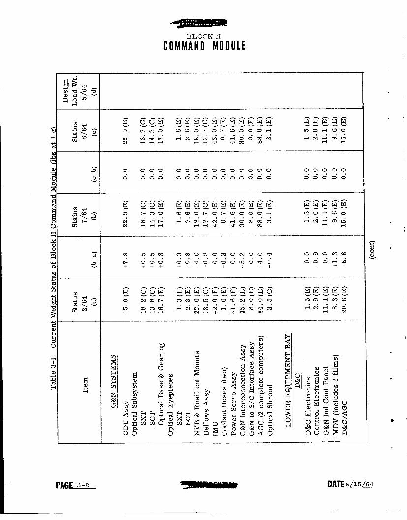
3-2 WEIGHTS
Table 3-1 presents the weight.s of the Block I1 Command Module concept de- fined in paragraph 3-1. Refer to paragraph 2-1 for a general explanation of weight reporting. No weight changes were reported this month
3-3 RELIABILITY
The reliability numbers shown in table 3-11 do not assume the use of in-flight spares or repair but do include the use of a redundant computer. Estimated Com- mand Module G&N reliability is based on t.he 138-hour mission a s defined in the Lunar Landing Mission Design Plan.
Table 3-11. Reliability (as of 5/15/64)
Sub system IMU AGC (2) DSKY PSA CDU (5) Optics
Operation Time fahr s> Probability of Mi s sion Success Full Power
31 1 g:!. 19 31:) 31 18
0.99576 0.99996 0.99995 0.99421 0.99426 0 e 99804
Total G&N System 0 98229
"Certain assemblies function continuously
I
I.3LC-xX IJ COMMAND M O D U L E
0 0 0 0 o o c o o o o o o o o 0 0 0 0 0 . . . 0 0 0 0 d 0 0 0 0 d O O d d d d d o o o
Q, u3LDm m m G C C O K l O C U O O d ' 0 Q ) o m w
+ + + + + + 1 ' I E + I I + I d d d A u j
n kl
.
D A T F W ?

- C O M M A N D M O D U L E
BLOCK II
I .
~
h
cd I e
PAGE-3-3

BLOCK I1
C O M M A N D M O D U L E
3-4 POWER REQUIREMENTS
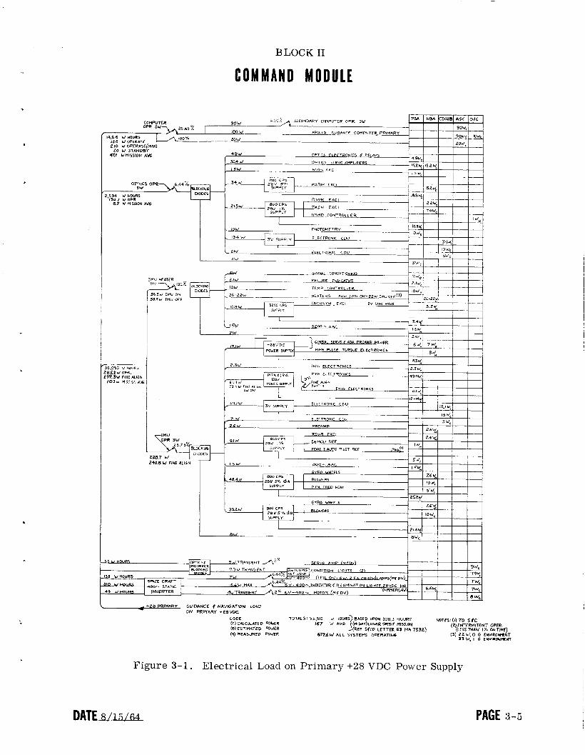
The power requirements of the Block I1 Command Module G&N equipment on the primary t28 VDC power supply are shown in figure 3-1, which presents the magnitude and location of dissipated power values on a subassembly level. This char t assumes a 14-day lunar orbit mission as defined by S&ID for power profile computation (Ref: S&ID letter 64 MA 3540).
Table 3-111 shows the energy consumptions on a G&N activity and G&N equipment basis . The vertical column to the left indicates the various G&N activities (phases of operation). This column also indicates the power requirement and operating t ime for each specific activity. The top row indicates the power requirement and operating time of each G&N power-consuming equipment e
PAGE 3-4 DATF8/15/64
BLOCK I1
COMMAND MODULE
LO W STANDBY *.I U MISSION A W
I m
L +ZB PRIWRY GUIDANCE P NAVIGATION LOAD - ON PRltiRRT +28VDC
CODE (C) C4LCULATED WUER
(M) FIEASURCD WWR 677.6W ALL SYSTEMS OPERATINS (el ESTIUATED POWER
33 W , I G ENVIRON*TNI
Figure 3-1. Electrical Load on Primary +28 VDC Power Supply
DATE SJSLM PAGE 3-5

Section 4
LUNAR EXCURSION MODULE DATA
e 4-1 do not assume the use of in-flight spares or repair, are b a e d on MIThL's Guidance Monitor System Note No. 3,
Table 4-1; Relkbility (as of 8/15/64)
4-2
e presented in table 4-II. In general the ed in paragraphs 2-1, 2-1. I, and 2-1.2.
stem" is inserted to provide for c o m p ~ ~
.
4-3.1 NVB (+6.0 lbs. ). The navigation base has been identified a8 an MITfwt igned item. It will be hard (ball) mounted as a result of GAEC 1 of the flight vibration environment (by a factor of 5) at NASA Coo L7A thereby eliminating the need for vibration isolation.
I
- - h

. . . . ” .
Q) d
$ k ..I
B Q) n c,
-
L U N A R E X C U R S I O N M O D U L E
* *
0 0 0 00 0 0 0 0 0 0 0 0 0
O d d d d ~ o o d o d o o w +
m o o 00 o m o o u 3 o o o o
+ I I I g o 0 00 0 ~ 0 0 ~ & 0 0 d
0
+ cd
Q,
4 +
. _
I ,.,A. .’*
I
-
LUNAR EXCURSION MODULE
UIREMENTS
for LEM power and energy consumption shown in figure Module G&N Block 11 Data and Preliminmy ICD WS-
dAnalysis Form.
the energy requirements for each G&N activity on a power is dso based upon LEM ICD LIS-390-2. The vertical d- s the various G&N activities (phases of operation). The ml- pbwer requirement and operating time for each specific ac- dicates the power requirement and operating time of each QM
ent. The table sums up the energy consumption for powq

L U N A R EXCURSION MODULE
PSA IMU AGC D U
OSW
STANDBY
.bLO W WUKS 05 W OPERATE 10 W STANDBY
.. c
5w, I
-'M aw - - $-&SI/ IH" o r sa
I I
__ -
- _ Figure 4-4. Electrical Load on Primary +28 VDC Power Supply
PAG& DATE~/l l i1;64
c
t
Y

LUNAR EXCURSION MODULE
a r?
In 0" 0'
n l- oo 4.
n 2 d 8 a' a' T m =:
" I
n 0 0
d
n l- d
d
0) In 0
d
* s i m'
I I
;;j N t d e
0 0 0
I d
0 N
d
N" d 0

Section 5
GLOSSARY AND SYSTEM DEFINITION
4
The following definitions apply to: (1) the Block I 100 ser ies systems and (2) the Block I1 and LEM systems defined prior to the recognition of the additional functions of spacecraft stabilization and control
Apollo Guidance -- Computer (AGC)
CM BLOCK I A single complete flight computer containing a l l lngic, mem-my, associated power supplies, and all interface circuits except those identified with the CDU's, Does not contain the associated displays and controls.
Consists of one case containing factory replaceable electronic modules. Includes cover for moisture proofing, but does not include the necessary cold plate o r the G&N to S/C Interface Assembly which is located in the adjacent area.
CM BLOCK 11 Two complete and active computers each having the same functions as the Block I AGC . Consists of two wiring matrix headers mounted on each side of the cold plate. This cold plate is not included in this accounting and must be moved up from the Block I configuration location. The modules of the "X" computer mount on one of these headers, those of the " Y t r computer on the other.
Block I and Block I1 AGC's a re not interrhangeable,
LEM A single complete flight computer having the same functions as one of the Block I1 computers it, the LEM computer will be physically identical with the Block I1 computers.
Unless installation constraints yet to be determined prevent
- AGC Covers
CM BLOCK I Required for moisture-proofing.
CM BLOCK I1 Two covers, one for each computer, may be required if it becomes necessary to seal the Mako connectors against moisture.
LEM Same as Block I1 except that there is only one cover.
RATE8/15/64 P A G W
Algnment __._--._______.I_.- Optical Telescope ( , A 0 3 I
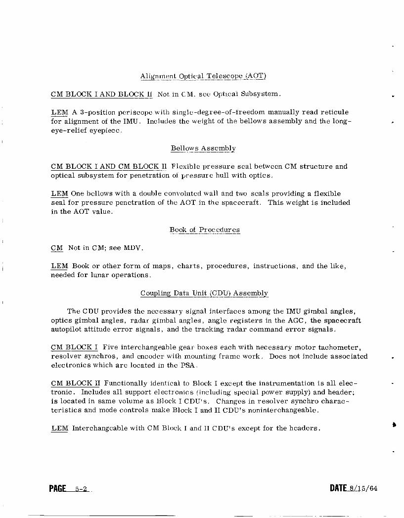
CM BLOCK I AND BLOCK 11 Not, in CM, see Optlcai Subsystem.
LEM A 3-position periscope with single-degr ee-of-ireedom manually read reticule for alignment of the IMU. Includes the weight of the bellows assembly and the long- eye-relief eyepiece”
Bellows Assembly
CM BLOCK I AND CM BLOCK 11 Flexible pressure seal between CM structure and optical subsystem for penetration of pressure hull with optics.
LEM One bellows with a double convoluted wa l l and two seals providing a flexible seal for pressure penetration of the AOT in the spacecraft. This weight is included in the AOT value.
Book of Procedures
CM Not in CM; see MDV. -
LEM Book or other form of maps, charts, procedures, instructions, and the like, needed for lunar operations
Coupling Data Unit 1CDU) -__- A s s e m b a
The CDU provides the necessary signal interfaces among the IMU gimbal angles, optics gimbal angles, radar gimbal angles, angle registers in the AGC, the spacecraft autopilot attitude e r r o r signals and the tracking radar command e r r o r signals.
CM BLOCK I Five interchangeable gear boxes each with necessary motor tachometer, resolver synchros, and encoder with mounting frame work electronics which a r e located in the PSA I
Does not include associated
CM BLOCK I1 Functionally identical to Block I except the instrumentation is all elec- tronic. Includes all support electronics (including special power supply) and header; is located in same volume as Block I CDLJYs.. Changes in resolver synchro charac- teristics and mode controls make Block I and I1 CDUss noninterchangeable.
b LEM Interchangeable with C M Block I and I1 C D U v s except for the headers.
P A G U DATE 8/15/64
Cold Plates
.
CM BLOCK I, BLOCK 11, AND LEM Cold plates €or the IMU a r e built into the IMU. Necessary cold plates for electronics a r e part of the equipment supplied by the space- craft manufacturer. All cold surfaces otherwise open to the cabin environment will probably by insulated to prevent moisture condensation.
Control Electronics Assembly
CM BLOCK I Consists of one power transformer, one relay and diode module, and a bracket end connector. Used to support display and control functions. Includes moisture-proofing .
CM BLOCK I1 May be relocated with other similar functions.
LEM Not defined in LEM.
Cooland Hoses
CM BLOCK I AND CM BLOCK I1 Consists of (1) two steel flex coolant hoses, one between IMU and spacecraft and one between optics and spacecraft, (2) bracket assem- bly screws and clamp, and (3) entrapped coolant. Note that a third steel flex cool- an t hose between the optics and the IMU is considered a s part of the weight of the optics base.
LEM Not identified as part of LEM.
Disdav and Control/Alsollo Guidance ComDuter (D&C /AGC
CM BLOCK I Number displays and keyboard control associated with the operation of the AGC . Two functionally identical and parallel operation units: one in lower equip- ment bay and one on main panel between left and center couches.
CM BLOCK I1 Functionally identical to Block I but smaller configuration because of smaller relays.
LEM Identical to Block I1 except only a single unit is required.
D&C Electronics Assembly
CM BLOCK I Consists of a chassis, a relay and diode module, a demod. elect. module, a saturable reactor, a time delay module, a connector, and wiring. Used to support display and control functions e Connectors will be moisture-proofed.
P A G W

CM BLOCK I1 Not defined at this t ime.
LEM Not defined in LEM at this time.
for Reticule I
- CM NotinCM.
LEM Device o r equipment not yet defined in detail, to position the LEM pilot's eye to use the window marking reticule pattern for landing point observation and selec- tion during the constant flight path phase of landing.
Film I___- Cartrid=
CM BLOCK I AND CLOCK 11 Consists of film cartricges anc viewer.
LEM Does not exist in LEM - -- G&N Indicator Control Panel I
film for map and data
CM BLOCK I AND BLOCK -- I1 Consists primarily of controls and displays for the oper- ation of the optics, MDV, IMU temperature control, panel brightness control, and attitude impulse control. It includes display and control elements, panel, panel wiring, supporting hardware, and moisture-proofing
LEM Not defined at this time for LEM,
-___ G&N Interconnection Assembly
CM BLOCK I Consists of PSA End Connector Assembly and interconnect wiring harness, which electrically t ies together the assemblies that constitute a completely integrated system. This term does not include the G&N to S/C Interface Assembly weight o r the weights of harness support brackets which are an NAA responsibility.
CM BLOCK I1 Similar to Block I but not interchangeable with Block I . c
LEM Not clearly defined but at present is called the AGC/PSA Interconnection Assy. Because of the wide separation of G&N components, most interconnection will be accom- plished as part of spacecraft wiring,
P A G W D A T E 6 4

G&N to S I C Interface - Assembly
CM BLOCK I Cable interconnections between the spacecraft wiring channel, the computer end connector, and the PSA end connector. Contains no active electronics.
CM BLOCK 11 Similar in function to Block I except the configuration is much dif- ferent and not interchangeable with Block I D
LEM Not identified yet a s a separate item in LEM.
Horizon Photometer ---.
c1.M BLOCK I AND BLWK II AE earth b a r i ~ o n br ight~ess photoiiizter 2nd aiitoiiiatic star tracker fo r navigation measurements against the earth 's illuminated limb. The sensors a r e incorporated into the head of the SXT, the weight of which includes this function. The PSA includes all support electronics for Block I1 and some of the support electronics for Block I .
LEM Not a part of LEM.
Horizon Photometer Electronics -.
CM BLOCK I Additional horizon photometer and star t racker electronics located on an auxiliary header attached to the right-hand wall behind the MDV.
CM BLOCK I1 AND LEM Not required.
Inertial Measurement Unit (r?ll_v! -__I
CM BLOCK I Size 14 IMU (14-inch case diameter) gimbal assembly including all par t s inside hermetic case, entrapped coolant, and heat exchanger insulation.
CM BLOCK I1 Size 1 2 . 5 IMU functionally interchangeable with Block I unit, but not physically interchangeable with Block I .
LEM Size 1 2 . 5 IMU a s described above.
P A G W

.
IMU Control Panel _I___-
CM BLOCK - I Consists of panel, wiring, attitude e r r o r meter, CDU transfer switch, manual alignment switch, CDU mode control switches, connector, supporting hardware, and associated moisture-proofing ,
CM BLOCK I1 Does not exist in Block 11. Moding is done by AGC program and AGC push buttons.
.
LEM Not defined a t this time for LEM.
- Long- Eye-Relief --_ Eyepieces
CM BLOCK I AND BLOCK 11 Consists of a SXT and a SCT eyepiece to provide eye relief of at least 1 . 6 inches for closed-visor operat,ion. Used in place of normal eyepieces of SXT and SCT.
LEM Long- eye-r elief eyepiece is included a s part of the AOT. =
Map and Data Viewer (MDV) - _-______ *
CM BLOCK I AND BLOCK I1 Film viewer for display of maps, charts, procedures, and the like. Weight includes one film cartridge for Block I MDV and tentatively two for Block I1 MDV. An MDV cover is included in the Block I weight only.
LEM Not in LEM; see Book of Procedures
NVB and Resilient Mounts
CM BLOCK I Rigid beryllium st,ructure supporting the IMU and the optical subsystem with its associated hardware. The NVB is attached to the spacecraft using flexible re- silient mounts to prevent spacecraft strains from distorting the NVB and the alignment between the IMU and optics. These mounts also provide shock and vibration attenuation.
CM BLOCK I1 Functionally similar to Block I but will be lighter and provide for mounting the size 1 2 . 5 IMU.
LEM A toroidal aluminum ring with: (1) four tubular aluminum posts to provide for IMU mounting, (2) four tubular aluminum posts for AOT mounting, and (3) three aluminum inserts to provide strain isolation ball mounting to the GAEC structure.
P A G E . DATE 8/15/64

Optical Eyepieces
.
CM BLOCK I AND BLOCK I1 Remo.irable SXT eyepiece and SCT eyepiece.
LEM Included as part of the AOT.
Optical Subsystem I- -
CM BLOCK I AND BLOCK II Consists of SXT and SCT, Optical Base, and associated hardware defined as follows:
SXT:
SC T:
Optical Base:
Sextant. A two-line-of-sight, narrow-field, tw o-degree-of -freedom sextant and its attached gearing The horizon photometer and automatic star tracker sensors a r e incorporated into the SXT head.
Scanning Telescope. A single-line-of-sight, wide-field-of-view , two-degree-of-freedom articulation optical instrument and its at- tached gearing.
Base for SXT and SCT with associated gear- ing and internal cooling. Includes the weight of the coolant hose between the IMU and Optical Base.
LEM Not in LEM; see AOT.
Optical Shroud & Cover Assembly
CM BLOCK I AND BLOCK I1 Consists of the optical shroud and protective cover.
LEM Does not exist in LEM. - Power Servo -- Assembly (PSI)*
CM BLOCK I Includes most of the support electronics: power supplies; IMU, Optics, and CDU servos; IMU temperature control; accelerometer and gyro pulse torquing; and horizon photometer and automatic star tracker electronics. Consists of 10 trays with replaceable modules which plug into the PSA end con- nector assembly. Includes front toe plate but not the cold plate.
DATE8/15/64

C M BLOCK I1 Similar in function to Block I but does not contain the CDU servos needed in Block I . Consists of a single plane matrix header to mount onto the cold plate with the modules plugging onlo the top.
LEM Consists of electronics similar to those identified in the Block I1 PSA minus various electronics modules Does not include optics and photometry electronics associated with the Block I and I1 PSA’s
PSA End Connector Assembly
CM BLOCK I Electrical interconnection between the PSA trays, the G&N Intercon- nection Assy, and the G&N to S/C Interface A s s y . reported in the G&N Interconnection Assembly weight
The End Connector weight is
CM BLOCK IIAND LEM Not identified a s a separate item; will be part of the PSA matrix header.
PSA Covers
CM BLOCK I Not required.
CM BLOCK I1 Cover to protect the PSA module connections from moisture during flight.
LEM Same as Block I1 except lighter i n weight.
. SAnal Conditioner A s s e m 2 -
CM BLOCK I AND BLOCK I1 AND -- LEM Conditions signals for telemetry.
Two-Digit Readout for Reticle
- CM NotinCM.
LEM A 2-digit readout driven by the AGC from 00 to 99 to indicate range component of landing point using fixed numbered scale on window reticule.
c
P A G E D A T E / @

DISTRIBUTION LIST E-1142, Rev. 22
Alonso, R. Apollo Library (15) Battin, R. Bean, W. Bowditch, P. Boyce, A. Bryant, P. copps: s. Dahlen, J. Dunipace, K. (AMR) Duggan, E. Flanders , J . Felix, S. (S&ID)
Apollo Limited Internal
Hall, E , C, Halzel, I. Hanley, D. Hickey, E . Hoag, D. Houston, F. Hursh, J. Koso. A . Kramer, M. Kupfer, W. Ladd, D. Lawrence, J. (GAEC) Lawton. T.
Mayo, G. Miller, J MIT/IL Library (W-1) (8) Nevins , J. Nugent, J . Olsson, E.A. Sciegienny , J. Sears: N. Stameris, W. Trageser, M. Wilk, L(2) Woodbury, R.
External
Delaney, Capt. W. (AFSC/MIT) (1) Small, J. (GAEC/RASPO) (1) Gregorek, S. (NAA S&ID/MIT) (1) AC Spark Plug (1 0) Heuermann, T. (GAEC/MIT) (1) Koll sman (10) Rhine, W. (NASA/RASPO/MIT) (1) Raytheon (10)
NAA RASPO: National Aeronautics and Space Administration (1) Resident Apollo Spacecraft Project Officer North American Aviation, Inc. Space and Information Systems Division 12214 Lakewood Boulevard Downe y , California
HDQ:
GAEC:
NASA Headquarters 1560 H Street Washington, D. C , Attn: Mr. G.M. Low, MD(P)
Grumman Aircraft Engineering Corporation Bethpage, Long Island New York Attn: M r . A. Whitaker
P A G L

NAA:
MSC:
WESCo:
North American Aviation. Inc. Space and Information Systems Division 122 14 La kewoo d fiouleu a rd Downey Calibrni a Attn Mr. . R Berry (1)
National Aeronautics and Space Administration Manned Spacecraft, Center Houston 1, Texas Apollo Document Control Group (SDG) (35) Apollo Command and Service Module (3) Attn. Mr.. F Pe ters Attn. MI-. Po Ebersole (2)
(41)
Washington Engineering Services Co., Inc. White Flint Science Pa rk Kensington Maryland Attn" Mr . J. P. Smith
WESCo 68 Rogers Street Cambridge 39. Massachusetts Attn. Mr I ?To Levy (2)
ACSP RASPO: National Aeronautics arid Space Administration (1) Resident Apollo Spacecraft Program Officer Dept. 32-31 AC Spark Plug Division of General Motors Milwaukee, Wi sconsin Attn. M r L, J, Lewandowski
Mr. H . Peterson Bureau of Naval Weapons c/o Raytheon Company Foundry Avenue Waltham Massachusetts
Mr. H . Rothstein
111 East 16th Street New York 3 , New York
USAF - NYCMD
Mr, H . Anschuetz USAF C0ntrac.t Management District AC Sparh Plug Division of General Motors Milwaukee , Wisconsin 532 0 1
P A G E