caloric anlagenbau gmbh · pdf file8 caloric anlagenbau gmbh gas sweetening plants amine...
TRANSCRIPT
CALORIC ANLAGENBAU GMBH
2 Caloric Anlagenbau GmbH
CALORIC ANLAGENBAU GMBH
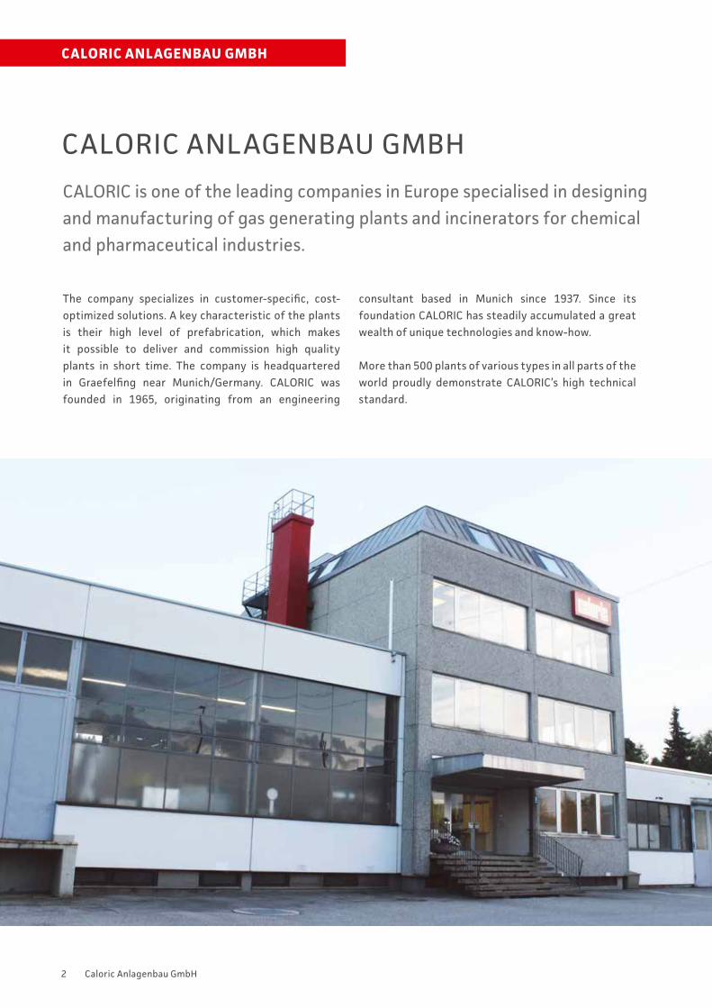
CALORIC is one of the leading companies in Europe specialised in designing and manufacturing of gas generating plants and incinerators for chemical and pharmaceutical industries.
The company specializes in customer-specific, cost-optimized solutions. A key characteristic of the plants is their high level of prefabrication, which makes it possible to deliver and commission high quality plants in short time. The company is headquartered in Graefelfing near Munich/Germany. CALORIC was founded in 1965, originating from an engineering
consultant based in Munich since 1937. Since its foundation CALORIC has steadily accumulated a great wealth of unique technologies and know-how.
More than 500 plants of various types in all parts of the world proudly demonstrate CALORIC’s high technical standard.
CALORIC ANLAGENBAU GMBH
3Caloric Anlagenbau GmbH
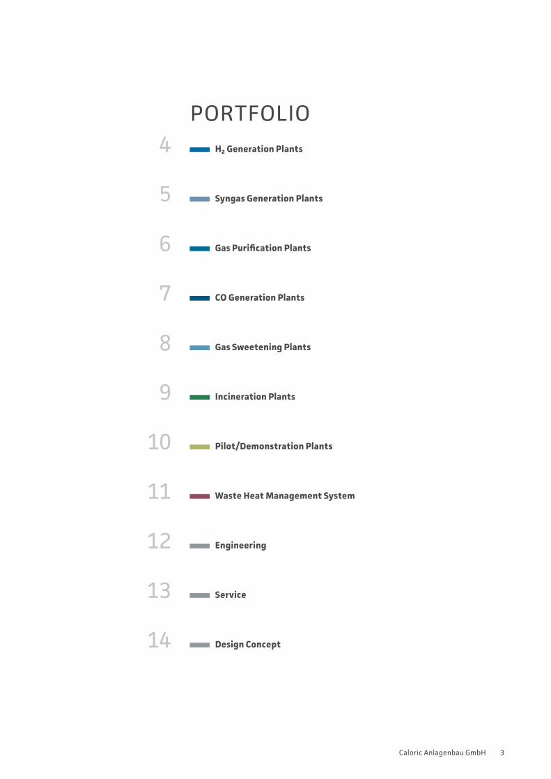
PORTFOLIO H₂ Generation Plants
Syngas Generation Plants
Gas Purification Plants
CO Generation Plants
Gas Sweetening Plants
Incineration Plants
Pilot/Demonstration Plants
Waste Heat Management System
Engineering
Service
Design Concept
5
4
6
7
8
9
10
11
12
13
14
4 Caloric Anlagenbau GmbH
H2 Generators
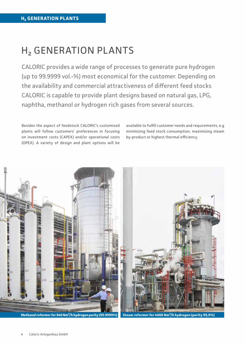
H₂ GENERATION PLANTS
CALORIC provides a wide range of processes to generate pure hydrogen
(up to 99.9999 vol.-%) most economical for the customer. Depending on
the availability and commercial attractiveness of different feed stocks
CALORIC is capable to provide plant designs based on natural gas, LPG,
naphtha, methanol or hydrogen rich gases from several sources.
Besides the aspect of feedstock CALORIC’s customised plants will follow customers’ preferences in focusing on investment costs (CAPEX) and/or operational costs (OPEX). A variety of design and plant options will be
available to fulfill customer needs and requirements, e.g minimizing feed stock consumption, maximizing steam by-product or highest thermal efficiency.
H₂ GENERATION PLANTS
Methanol reformer for 840 Nm³/h hydrogen purity (99.9999%) Steam reformer for 4000 Nm³/h hydrogen (purity 99,9%)
5Caloric Anlagenbau GmbH
SYNGAS GENERATION PLANTS
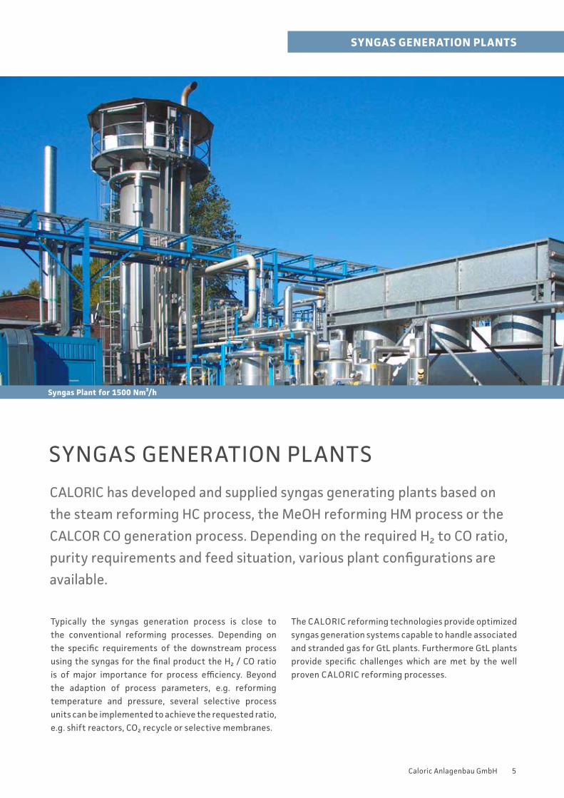
CALORIC has developed and supplied syngas generating plants based on
the steam reforming HC process, the MeOH reforming HM process or the
CALCOR CO generation process. Depending on the required H₂ to CO ratio,
purity requirements and feed situation, various plant configurations are
available.
Syngas Plant for 1500 Nm³/h
SYNGAS GENERATION PLANTS
Typically the syngas generation process is close to the conventional reforming processes. Depending on the specific requirements of the downstream process using the syngas for the final product the H₂ / CO ratio is of major importance for process efficiency. Beyond the adaption of process parameters, e.g. reforming temperature and pressure, several selective process units can be implemented to achieve the requested ratio, e.g. shift reactors, CO₂ recycle or selective membranes.
The CALORIC reforming technologies provide optimized syngas generation systems capable to handle associated and stranded gas for GtL plants. Furthermore GtL plants provide specific challenges which are met by the well proven CALORIC reforming processes.
6 Caloric Anlagenbau GmbH
GAS PURIFICATION PLANTS
CALORIC offers several processes to purify gas streams most cost efficient
for the customer (up to 99.9999 vol.-%). A variety of design options will be
available to fulfill customer requirements, based on catalytic, absorptive
and adsorptive processes as well as selective permeation.
A variety of design and process plant options will be available to fulfill customer needs and requirements, e.g. PSA or membrane
Membrane PurificationClean gas is generated by purification of the the feed gas using membrane technology of globally leading suppliers. Depending on the required product purity and the efficiency, the system including amount and configuration of membranes are arranged.
GAS PURIFICATION PLANTS
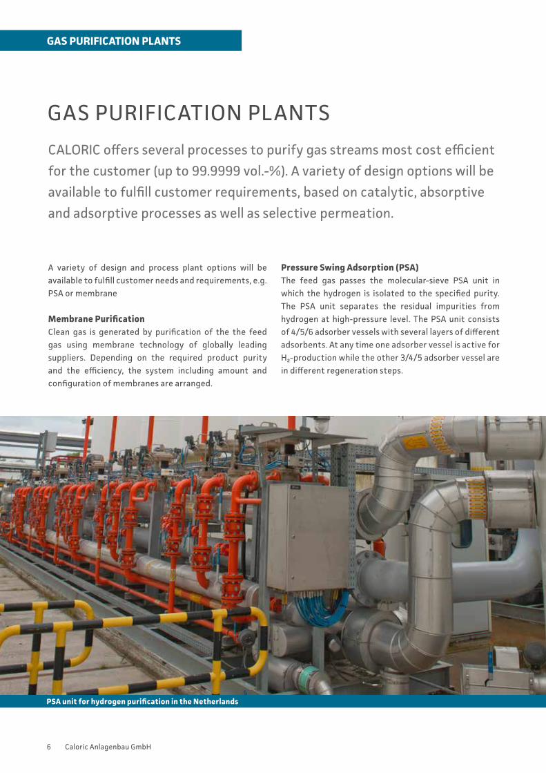
PSA unit for hydrogen purification in the Netherlands
Pressure Swing Adsorption (PSA)The feed gas passes the molecular-sieve PSA unit in which the hydrogen is isolated to the specified purity. The PSA unit separates the residual impurities from hydrogen at high-pressure level. The PSA unit consists of 4/5/6 adsorber vessels with several layers of different adsorbents. At any time one adsorber vessel is active for H₂-production while the other 3/4/5 adsorber vessel are in different regeneration steps.
7Caloric Anlagenbau GmbH
CO-GENERATION PLANTS
CO-GENERATION PLANTS
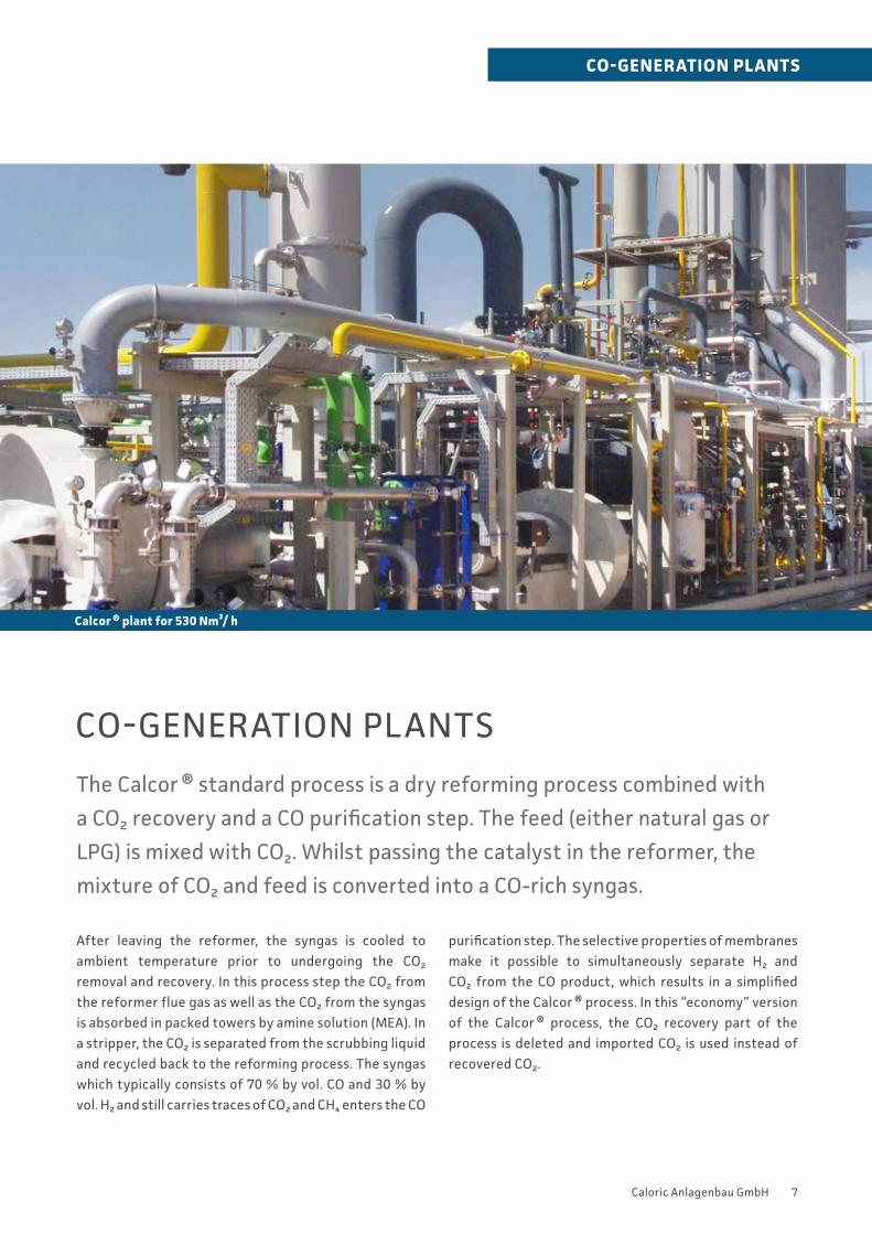
The Calcor ® standard process is a dry reforming process combined with
a CO₂ recovery and a CO purification step. The feed (either natural gas or
LPG) is mixed with CO₂. Whilst passing the catalyst in the reformer, the
mixture of CO₂ and feed is converted into a CO-rich syngas.
After leaving the reformer, the syngas is cooled to ambient temperature prior to undergoing the CO₂ removal and recovery. In this process step the CO₂ from the reformer flue gas as well as the CO₂ from the syngas is absorbed in packed towers by amine solution (MEA). In a stripper, the CO₂ is separated from the scrubbing liquid and recycled back to the reforming process. The syngas which typically consists of 70 % by vol. CO and 30 % by vol. H₂ and still carries traces of CO₂ and CH₄ enters the CO
purification step. The selective properties of membranes make it possible to simultaneously separate H₂ and CO₂ from the CO product, which results in a simplified design of the Calcor ® process. In this “economy” version of the Calcor ® process, the CO₂ recovery part of the process is deleted and imported CO₂ is used instead of recovered CO₂.
Calcor ® plant for 530 Nm³/ h
8 Caloric Anlagenbau GmbH
GAS SWEETENING PLANTS
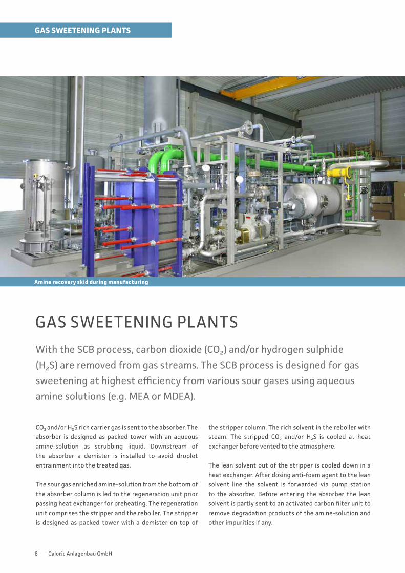
Amine recovery skid during manufacturing
GAS SWEETENING PLANTS
With the SCB process, carbon dioxide (CO₂) and/or hydrogen sulphide
(H₂S) are removed from gas streams. The SCB process is designed for gas
sweetening at highest efficiency from various sour gases using aqueous
amine solutions (e.g. MEA or MDEA).
CO₂ and/or H₂S rich carrier gas is sent to the absorber. The absorber is designed as packed tower with an aqueous amine-solution as scrubbing liquid. Downstream of the absorber a demister is installed to avoid droplet entrainment into the treated gas.
The sour gas enriched amine-solution from the bottom of the absorber column is led to the regeneration unit prior passing heat exchanger for preheating. The regeneration unit comprises the stripper and the reboiler. The stripper is designed as packed tower with a demister on top of
the stripper column. The rich solvent in the reboiler with steam. The stripped CO₂ and/or H₂S is cooled at heat exchanger before vented to the atmosphere.
The lean solvent out of the stripper is cooled down in a heat exchanger. After dosing anti-foam agent to the lean solvent line the solvent is forwarded via pump station to the absorber. Before entering the absorber the lean solvent is partly sent to an activated carbon filter unit to remove degradation products of the amine-solution and other impurities if any.
9Caloric Anlagenbau GmbH
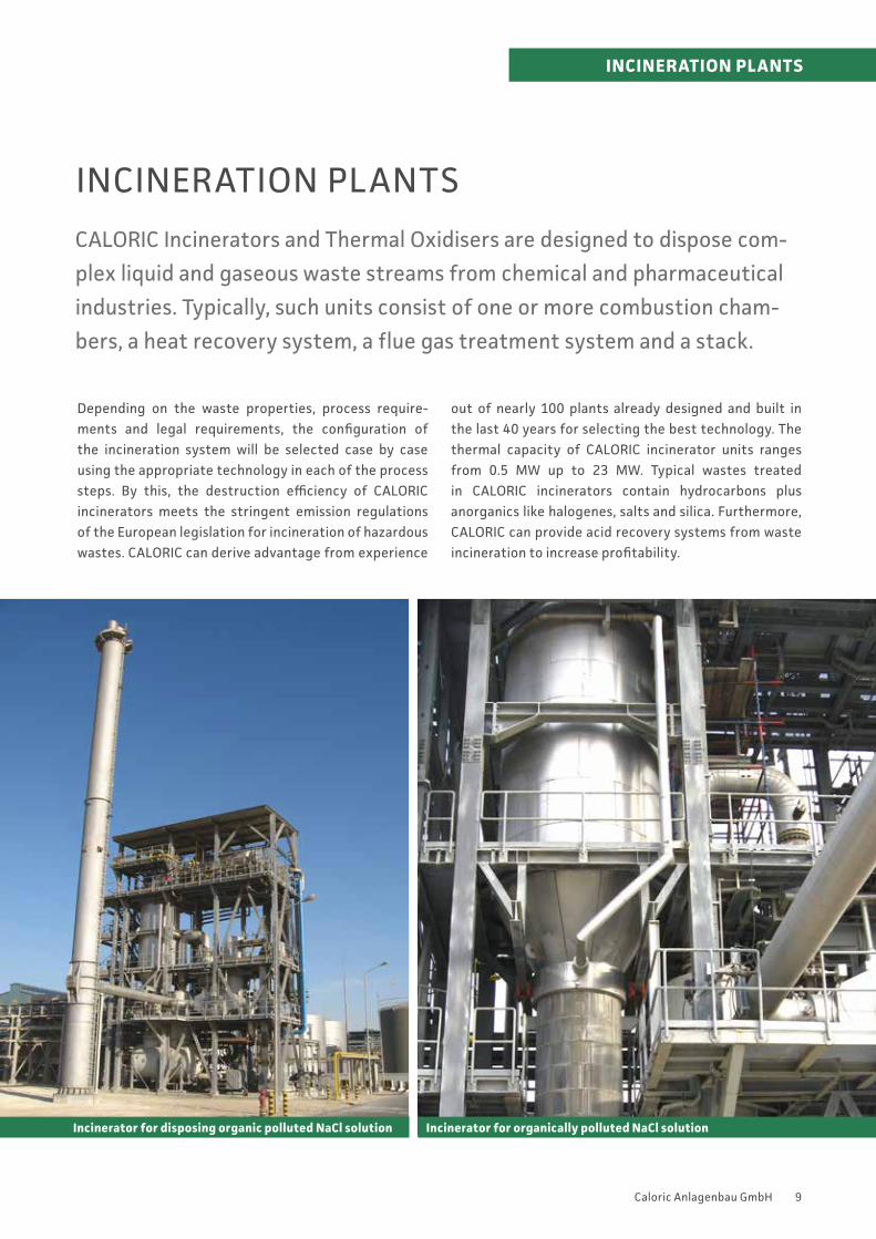
INCINERATION PLANTS
CALORIC Incinerators and Thermal Oxidisers are designed to dispose com-
plex liquid and gaseous waste streams from chemical and pharmaceutical
industries. Typically, such units consist of one or more combustion cham-
bers, a heat recovery system, a flue gas treatment system and a stack.
Depending on the waste properties, process require- ments and legal requirements, the configuration of the incineration system will be selected case by case using the appropriate technology in each of the process steps. By this, the destruction efficiency of CALORIC incinerators meets the stringent emission regulations of the European legislation for incineration of hazardous wastes. CALORIC can derive advantage from experience
out of nearly 100 plants already designed and built in the last 40 years for selecting the best technology. The thermal capacity of CALORIC incinerator units ranges from 0.5 MW up to 23 MW. Typical wastes treated in CALORIC incinerators contain hydrocarbons plus anorganics like halogenes, salts and silica. Furthermore, CALORIC can provide acid recovery systems from waste incineration to increase profitability.
INCINERATION PLANTS
Incinerator for organically polluted NaCl solutionIncinerator for disposing organic polluted NaCl solution
10 Caloric Anlagenbau GmbH
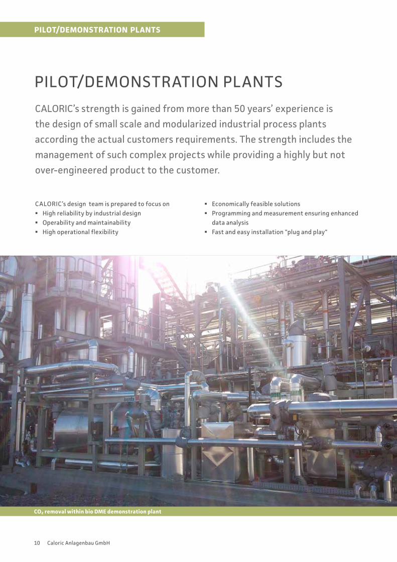
PILOT/DEMONSTRATION PLANTS
CALORIC’s strength is gained from more than 50 years’ experience is
the design of small scale and modularized industrial process plants
according the actual customers requirements. The strength includes the
management of such complex projects while providing a highly but not
over-engineered product to the customer.
CALORIC’s design team is prepared to focus on § High reliability by industrial design § Operability and maintainability § High operational flexibility
§ Economically feasible solutions § Programming and measurement ensuring enhanced
data analysis § Fast and easy installation "plug and play"
PILOT/DEMONSTRATION PLANTS
CO2 removal within bio DME demonstration plant
11Caloric Anlagenbau GmbH
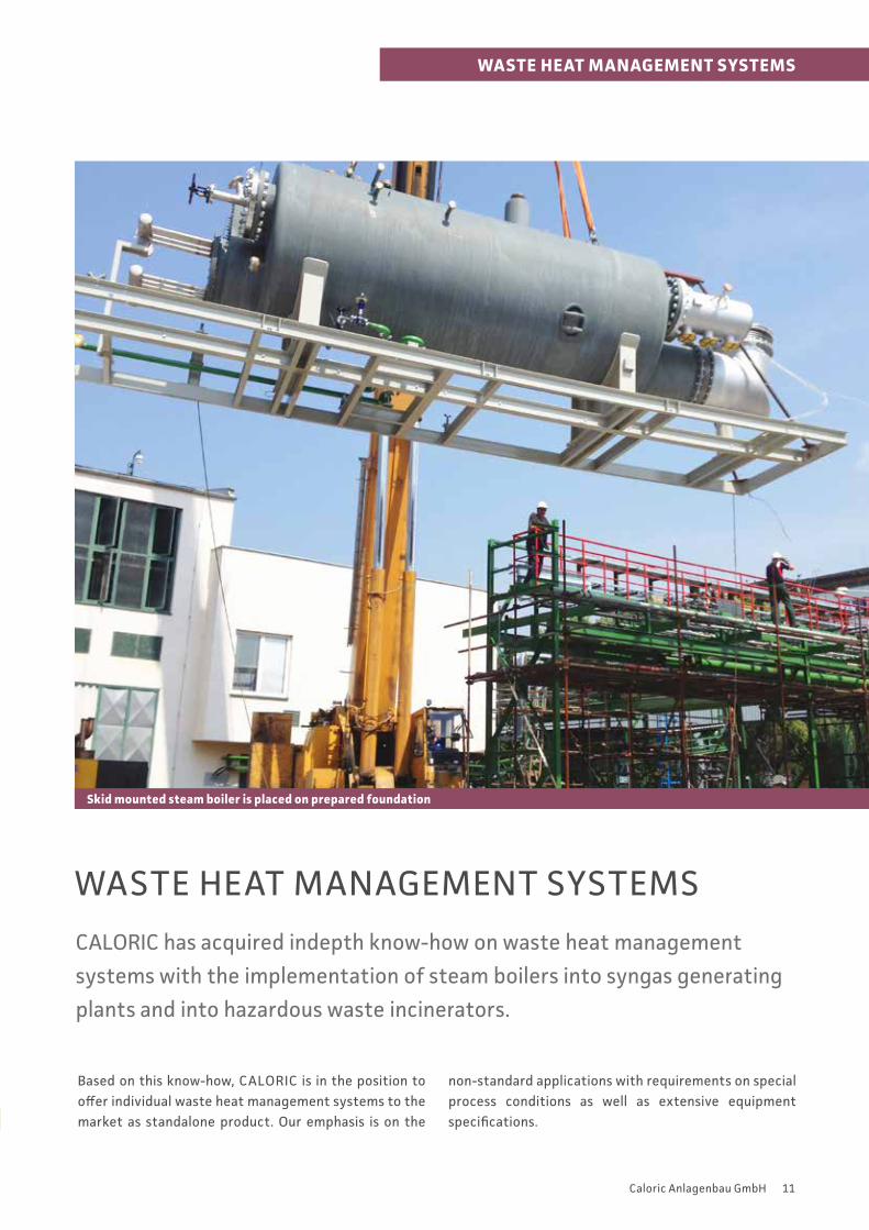
WASTE HEAT MANAGEMENT SYSTEMS
Skid mounted steam boiler is placed on prepared foundation
WASTE HEAT MANAGEMENT SYSTEMS
CALORIC has acquired indepth know-how on waste heat management
systems with the implementation of steam boilers into syngas generating
plants and into hazardous waste incinerators.
Based on this know-how, CALORIC is in the position to offer individual waste heat management systems to the market as standalone product. Our emphasis is on the
non-standard applications with requirements on special process conditions as well as extensive equipment specifications.CO2 removal within bio DME demonstration plant
12 Caloric Anlagenbau GmbH
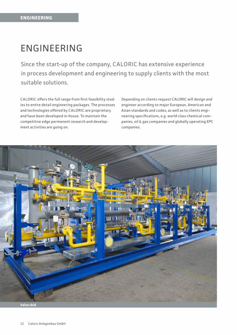
ENGINEERING
Since the start-up of the company, CALORIC has extensive experience
in process development and engineering to supply clients with the most
suitable solutions.
CALORIC offers the full range from first feasibility stud-ies to entire detail engineering packages. The processes and technologies offered by CALORIC are proprietary and have been developed in-house. To maintain the competitive edge permanent research and develop-ment activities are going on.
Depending on clients request CALORIC will design and engineer according to major European, American and Asian standards and codes, as well as to clients engi-neering specifications, e.g. world class chemical com-panies, oil & gas companies and globally operating EPC companies.
ENGINEERING
Valve skid
13Caloric Anlagenbau GmbH
SERVICE
SERVICE
One of CALORIC`s strengths is the support of our clients over the total
lifetime of their plants.
CALORIC provides services throughout the plant life cycle. The various services will start from turnkey erec-tion and comprises also operator training, optimisation of the process as well as complete maintenance sche-dules or revamp services.
§ Spare parts supply § Operator training § Process optimization
§ Remote services § Approval management § Maintenance § Revamps (process, mechanical, electrical)
CALORIC develops project specific schedules to get the job executed on time and within budget.
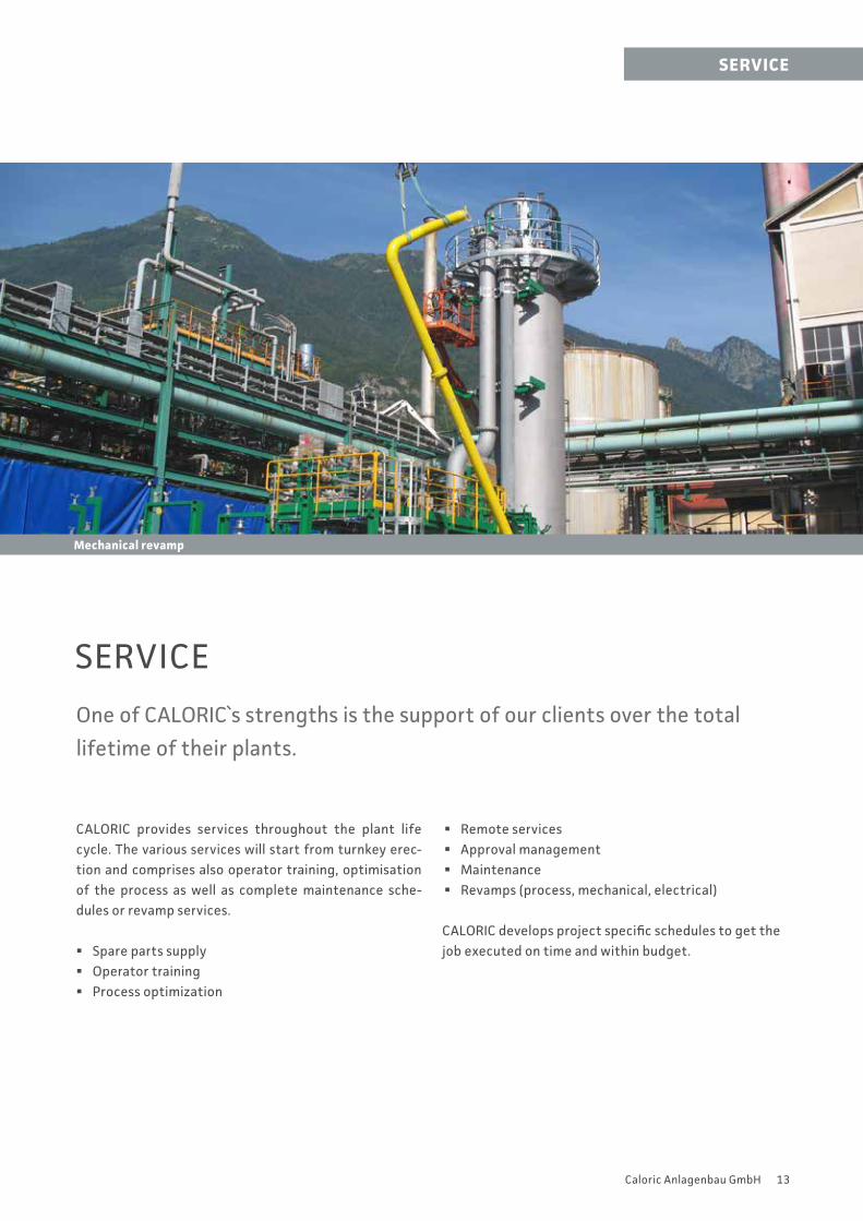
Mechanical revamp
14 Caloric Anlagenbau GmbH
DESIGN CONCEPT: MODULAR SKID CONSTRUCTION
A key component and basis for fixed prices and short delivery times is the
successful modular design concept of pre-manufactured skid-mounted
equipment for CALORIC’s various types of plants.
Due to this modular design concept the skids can be fully pre-fabricated and pre-assembled in CALORIC’s own factory. This includes fabrication, assembly, painting and cabling of the skids. To ensure highest quality, the entire
fabrication process is permanently controlled according to the quality management system and finalised by the FAT (factory acceptance test).
DESIGN CONCEPT
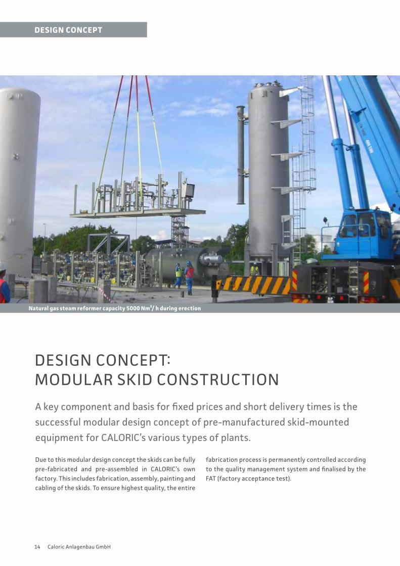
Natural gas steam reformer capacity 5000 Nm³/ h during erection
15Caloric Anlagenbau GmbH
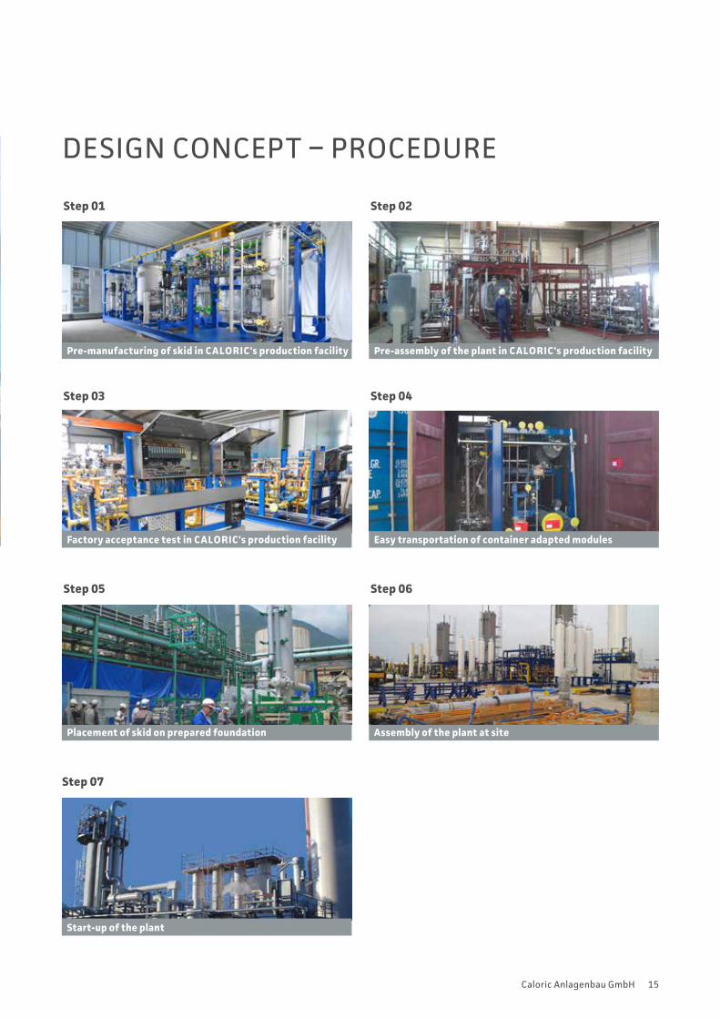
DESIGN CONCEPT – PROCEDURE
Step 03
Factory acceptance test in CALORIC's production facility
Step 01
Pre-manufacturing of skid in CALORIC's production facility
Step 04
Easy transportation of container adapted modules
Step 05
Placement of skid on prepared foundation
Step 06
Assembly of the plant at site
Step 07
Start-up of the plant
Step 02
Pre-assembly of the plant in CALORIC's production facility
PORTFOLIOCALORIC is one of the leading companies in Europe specialised in designing and manufacturing of gas processing plants, incinerators for chemical and pharmaceutical industries as well as related engineering performances and system supply.
H₂ Generation Plants
Syngas Generation Plants
Gas Purification Plants
CO Generation Plants
Gas Sweetening Plants
Incineration Plants
Pilot/Demonstration Plants
Waste Heat Management System
Engineering
Caloric Anlagenbau GmbH Lohenstrasse 12 82166 Graefelfing near Munich/GermanyTel. +49 89 89819 - 0 [email protected]
www.caloric.com