gobids.grayandosborne.com call for bids city of milton well 10 reconstruction engineer’s estimate...
TRANSCRIPT

CITY OF MILTONKING/PIERCE COUNTY WASHINGTON
CONTRACT PROVISIONS
for
WELL 10 RECONSTRUCTION
G&O #15622APRIL 2018


CB-1
CALL FOR BIDS
CITY OF MILTON
WELL 10 RECONSTRUCTIONENGINEER’S ESTIMATE $650,000
Sealed Proposals will be received by the undersigned at the City of Milton, 1000 LaurelStreet, Milton, Washington 98354, up to 2:00 p.m.; local time on Wednesday, May 2, 2018,for furnishing the necessary labor, materials, equipment, tools, and guarantees thereof toconstruct the Well 10 Reconstruction.
The work consists of furnishing all labor, materials, and equipment necessary for equippingof the new Well 10 including, but not be limited to, demolition of the existing well building,installing a pitless well adapter and submersible well pump, installing a control valve vaultand discharge pipeline, installing new exterior electrical panels with a canopy roofstructure, and all other associated electrical and control systems as well as site work andsurface restoration.
The Work shall be physically complete within 120 working days after the commencementdate stated in the Notice to Proceed. All bidding and construction is to be performed incompliance with the Contract Provisions and Contract Plans for this project and anyaddenda issued thereto that are on file at the office of the City Clerk, City Hall, Milton,Washington.
The Proposals will be publicly opened and read aloud shortly after the time and date statedabove. Proposals are to be submitted only on the form provided with the ContractProvisions. All Proposals must be accompanied by a certified check, cashiers check,money order, or bid bond payable to the “City of Milton” and in an amount of not less thanfive percent (5%) of the total amount bid.
Bid Documents may be examined at the office of the City of Milton, or the office of theProject Engineer, Gray & Osborne, Inc. Bid Documents for this project are available free-of-charge at the following website: “http://gobids.grayandosborne.com”. Bidders areencouraged to “Register” in order to receive automatic email notification of future addendaand to be placed on the “Bidders List”. For assistance, please call (206) 284-0860.Contract questions shall be directed only to the office of the Project Engineer.
A Prebid Conference is scheduled for Wednesday, April 25, 2018. The conference willbe held at the City Shop Site, 714 Kent Street, Milton, Washington 98354 at 10:00 a.m.(local time). Prospective bidders are encouraged to participate. No other site visits willbe permitted.
Financing of the Project has been provided by the City of Milton, Washington. The Cityof Milton expressly reserves the right to reject any or all Proposals and to waive minor

CB-2
irregularities or informalities and to Award the Project to the lowest responsive, responsiblebidder as it best serves the interests of the City.
(Signed) ELLIE HOOMANCITY CLERK
TC-1
CONTRACT PROVISIONS
TABLE OF CONTENTS
CITY OF MILTON
WELL 10 RECONSTRUCTION
PAGE NO.
CALL FOR BIDS
PART 1. BID DOCUMENTS
BIDDER’S CHECKLIST.........................................................................BC-1PROPOSAL ...................................................................................... P-1 – P-9PROPOSAL BOND ................................................................................. PB-1
PART 2. AGREEMENT AND BONDS
AGREEMENT ................................................................................. A-1 – A-3PERFORMANCE BOND .......................................................................... B-1PUBLIC WORKS PAYMENT BOND ...................................................... B-2
PART 3. GENERAL CONDITIONS
PART 4. TECHNICAL SPECIFICATIONS
PART 5. WAGE RATES
PART 6. APPENDIX
Appendix A – Geotechnical Report (For Information Only)Appendix B – Existing Well Logs

PART 1
BID DOCUMENTS

BC-1
BIDDER’S CHECKLIST
1. REQUIRED FORMS
The Bidder shall submit the following forms, which must be executed in full andsubmitted with the Proposal.
a. Proposal (including Statement of Bidder’s Qualifications) (Pages P-1 - P-9)b. Bid Deposit or Proposal Bond (PB-1)
2. AGREEMENT FORMS
The following forms (a., b., and c.) are to be executed and the following Certificates ofInsurance (d. and e.) are to be provided after the Contract is awarded and prior to Noticeto Proceed.
a. Agreement (Pages A-1 - A-3)b. Performance Bond (Page B-1)c. Public Works Payment Bond (Page B-2)d. Certificate of Insurancee. Certificate of Builders Risk Insurance

P-1
WELL 10 RECONSTRUCTION
PROPOSAL
City of Milton1000 Laurel StreetMilton, Washington 98354
The undersigned has examined the Work site(s), local conditions, the Contract, and all applicablelaws and regulations covering the Work. The following unit and lump sum prices are tendered asan offer to perform the Work in accordance with all of the requirements set forth in the Contractand all applicable laws and regulations.
As required by the Contract, a certified check, bank draft, cashier’s check or Proposal bond madepayable to the Owner is attached hereto. If this Proposal is accepted and the undersigned fail(s)or refuse(s) to enter into a contract and furnish the required performance bond, labor and materialpayment bond, special guarantee bonds (if required), required insurance and all other requireddocumentation, the undersigned will forfeit to the Owner an amount equal to five percent of theamount bid.
After the date and hour set for submitting the Proposals, no bidder may withdraw its Proposal,unless the Award of the contract is delayed for a period exceeding 60 consecutive calendar days.
The undersigned agrees that in the event it is Awarded the contract for the Work, it shall employonly Contractors and Subcontractors that are duly licensed by the State of Washington and remainso at all times they are in any way involved with the Work.
The undersigned agrees that the Owner reserves the right to reject any or all Proposals and towaive any minor irregularities and informalities in any Proposal.
The undersigned agrees that the Owner reserves the right to Award the Contract to thelowest responsible, responsive bidder whose Proposal is in the best interest of the Owner.The Owner will determine at the time of Award of the Contract which items will beincluded in the Contract.
PROPOSAL - Continued
P-2
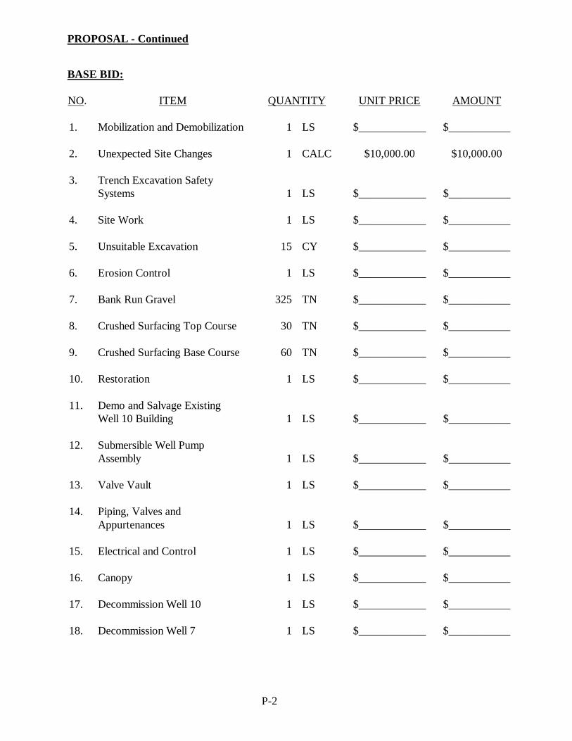
BASE BID:
NO. ITEM QUANTITY UNIT PRICE AMOUNT
1. Mobilization and Demobilization 1 LS $____________ $___________
2. Unexpected Site Changes 1 CALC $10,000.00 $10,000.00
3. Trench Excavation SafetySystems 1 LS $____________ $___________
4. Site Work 1 LS $____________ $___________
5. Unsuitable Excavation 15 CY $____________ $___________
6. Erosion Control 1 LS $____________ $___________
7. Bank Run Gravel 325 TN $____________ $___________
8. Crushed Surfacing Top Course 30 TN $____________ $___________
9. Crushed Surfacing Base Course 60 TN $____________ $___________
10. Restoration 1 LS $____________ $___________
11. Demo and Salvage ExistingWell 10 Building 1 LS $____________ $___________
12. Submersible Well PumpAssembly 1 LS $____________ $___________
13. Valve Vault 1 LS $____________ $___________
14. Piping, Valves andAppurtenances 1 LS $____________ $___________
15. Electrical and Control 1 LS $____________ $___________
16. Canopy 1 LS $____________ $___________
17. Decommission Well 10 1 LS $____________ $___________
18. Decommission Well 7 1 LS $____________ $___________
PROPOSAL - Continued
P-3
NO. ITEM QUANTITY UNIT PRICE AMOUNT
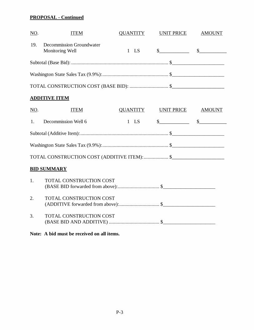
19. Decommission GroundwaterMonitoring Well 1 LS $____________ $___________
Subtotal (Base Bid): ........................................................................... $_____________________
Washington State Sales Tax (9.9%): ................................................... $_____________________
TOTAL CONSTRUCTION COST (BASE BID): .............................. $_____________________
ADDITIVE ITEM
NO. ITEM QUANTITY UNIT PRICE AMOUNT
1. Decommission Well 6 1 LS $____________ $___________
Subtotal (Additive Item): .................................................................... $_____________________
Washington State Sales Tax (9.9%): ................................................... $_____________________
TOTAL CONSTRUCTION COST (ADDITIVE ITEM): ................... $_____________________
BID SUMMARY
1. TOTAL CONSTRUCTION COST(BASE BID forwarded from above): ................................ $_____________________
2. TOTAL CONSTRUCTION COST(ADDITIVE forwarded from above): ............................... $_____________________
3. TOTAL CONSTRUCTION COST(BASE BID AND ADDITIVE) ....................................... $_____________________
Note: A bid must be received on all items.

PROPOSAL - Continued
P-4
ALTERNATES TO BID ITEMS
Bidders shall use this page to submit proposals on any alternate types of equipment or materialsthat bidders recommend the Owner consider using. Contract Award will be made on the basis ofequipment and materials that are specified. After Award, the Owner may consider any proposalalternates that, in the opinion of the Owner, will be equivalent to or better than the item specified.The Owner shall have complete discretion on whether to use any alternates, and the Owner’sdecision shall not be subject to challenge.
BASE BID:
Alternate toBid Item No. Item Manufacturer Amount Bid
ADDITIVE ITEM:
Alternate toBid Item No. Item Manufacturer Amount Bid

PROPOSAL - Continued
P-5
STATEMENT OF BIDDER'S QUALIFICATIONS
Name of Firm:
Address:
Telephone No. Fax No.
Contact Person for this Project:
E-mail:
Number of years the Contractor has been engaged in the construction business under the presentfirm name, as indicated above:
Gross dollar amount of work currently under contract:
Gross dollar amount of contracts currently not completed:
General character of work performed by firm:
List of five major projects of a similar nature which have been completed by the Contractor withinthe last five years and the gross dollar amount of each project, together with the Owner's nameand telephone number, and the Engineer’s name:
Project Name Amount Owner PhoneEngineer’s
Name

PROPOSAL - Continued
P-6
List five major pieces of equipment which are anticipated to be used on this project by theContractor and note which items are owned by the Contractor and which are to be leased orrented from others:
Bank Reference:
How many general superintendents or other responsible employees in a supervisory position doyou have at this time, and how long have they been with the firm?
Identify who will be the general superintendent and/or project superintendent on this project.Also, list the number of years each person identified has been with firm.
Have you changed bonding companies within the last three years?
If so, why?
Have you ever been a party to a lawsuit or an arbitration proceeding in any way relating toa construction project?
Identify the proceeding and parties and describe the claims asserted by all parties.
What was the disposition of the case?
Do you have any outstanding payments due to the Department of Revenue?
If yes, explain.
Bidder agrees that the Owner shall have the right to obtain credit reports.
Yes No

PROPOSAL - Continued
P-7
WORK COMPLETED BY CONTRACTOR
List the Work and the dollar amount thereof that the Contractor will complete with its forces, ifawarded the contract.
Work to be Performed Dollar Amount
PROPOSED SUBCONTRACTORS (Per RCW 39.30.060)
For Proposals exceeding one million dollars, indicate who (either the Contractor submitting thisbid or a subcontractor) will be completing the work for each of the three categories listed below.Information shall include their Washington State Department of Licensing Contractor'sRegistration No. This information shall be provided with the Proposal or within one hour afterthe published Proposal submittal time in accordance with RCW 39.30.060.
Work to be PerformedSubcontractor or Prime
(Name and Registration Number)Heating, Ventilation and Air Conditioning
Plumbing
Electrical

PROPOSAL - Continued
P-8
ADDENDA RECEIVED
Addendum No. Date Received Name of Recipient
NOTE: Bidder shall acknowledge receipt of all addenda. Bidder is responsible forverifying the actual number of addenda issued prior to submitting a Proposal.
Subject to any extensions of the Contract time granted under the Contract, the undersigned agreesto substantially complete the Work required under this Contract within 120 working days (theSubstantial Completion Date) and to physically complete the Work required under this contractwithin 130 working days (the Physical Completion Date) from when Contract Time begins.
The undersigned has reviewed and fully understands the provisions in the Contract regardingliquidated damages and agrees that liquidated damages shall be $1,000.00 per day for each andevery working day beyond the Contract time allowed for substantial completion until theSubstantial Completion Date is achieved and $750.00 for each and every working day requiredbeyond the Contract Time for physical completion until the Physical Completion Date is achieved.
The undersigned is, and will remain in, full compliance with all Washington State administrativeagency requirements including, but not limited to registration requirements of Washington StateDepartment of Labor & Industries for contractors, including but not limited to requirements forbond, proof of insurance and annual registration fee. The undersigned's Washington State:
Dept. of Labor and Industries Workman's Compensation Account No. is ___________________;Dept. of Licensing Contractor's Registration No. is ______________________________;Unified Business Identifier Number is ________________________________;Excise Tax Registration Number is ______________________________; andEmployment Security Account Number is _____________________________.
The undersigned has reviewed all insurance requirements contained in the Contract and hasverified the availability of and the undersigned’s eligibility for all required insurance. Theundersigned verifies that the cost for all required insurance, has been included in this Proposal.
In relation to claims related in whole or in part to workplace injuries to employees, theundersigned waives any immunity granted under the State Industrial Insurance Law, RCW Title51. This waiver has been specially negotiated by the parties, which is acknowledged by theundersigned in signing this Proposal.
By signing the proposal, the undersigned declares, under penalty of perjury under the laws of theUnited States and the State of Washington, that the following statements are true and correct:

PROPOSAL - Continued
P-9
1. That the undersigned person(s) or entity(ies) has(have) not, eitherdirectly or indirectly, entered into any agreement, participated inany collusion, or otherwise taken any action in restraint of freecompetitive bidding in connection with the project for which thisBid is submitted.
2. The bidder hereby certifies that, within the three-year period immediatelypreceding the bid solicitation date (April 17, 2018), that the bidder is not a“willful” violator, as defined in RCW 49.48.082, of any provision of chapters49.46, 49.48, or 49.52 RCW, as determined by a final and binding citation andnotice of assessment issued by the Department of Labor and Industries or througha civil judgment entered by a court of limited or general jurisdiction.
The undersigned agrees that the Owner is authorized to obtain information from all referencesincluded herein.
Sincerely,
Sign Name Date
By: Print Name, Title Location Executed (City, State)
Print Company Name
Amount of Proposal deposit: $ Check No. ,
or Proposal bond in the amount of $
, issued throughName of Bank/Bonding Company
located atMailing Address
Telephone Number of Bank/Bonding Company

PB-1
PROPOSAL BOND
KNOW ALL MEN BY THESE PRESENTS, That we
of as principal, and the a corporation duly organized under the laws of the state of , and authorized to do business in the State of Washington, as surety, are held and firmly bound unto the CITY OF MILTON in the full and penal sum of five percent of the total amount of the bid proposal of said principal for the work hereinafter described, for the payment of which, well and truly to be made, we bind our heirs, executors, administrators and assigns, and successors and assigns, firmly by these presents. The condition of this bond is such, that whereas the principal herein is herewith submitting his or its sealed proposal for the following construction project, to wit:
WELL 10 RECONSTRUCTION said bid and proposal, by reference thereto, being made a part hereof. NOW, THEREFORE, If the said proposal bid by said principal be accepted, and the contract be awarded to said principal, and if said principal shall duly make and enter into and execute said Contract and shall furnish bond as required by the CITY OF MILTON within a period of 10 days from and after said award, exclusive of the day of such award, then this obligation shall be null and void, otherwise it shall remain and be in full force and effect. IN TESTIMONY WHEREOF, The principal and surety have caused these presents to be signed and sealed this day of , __________.
(Principal) (Surety) (Attorney-in-fact)

PART 2
AGREEMENT AND BONDS

A-1
AGREEMENT
THIS AGREEMENT is entered into by and between the CITY OF MILTON (hereinaftercalled the Owner) and __________________________________________ (hereinaftercalled the Contractor).
The Owner and the Contractor agree as follows:
ARTICLE 1. WORK.
The work consists of furnishing all labor, materials, and equipment necessary for equippingof the new Well 10 including, but not be limited to, demolition of the existing well building,installing a pitless well adapter and submersible well pump, installing a control valve vaultand discharge pipeline, installing new exterior electrical panels with a canopy roofstructure, and all other associated electrical and control systems as well as site work andsurface restoration.
ARTICLE 2. CONTRACT TIME.
The Contractor shall substantially complete the Work required by the Contract within________ working days (the Substantial Completion Date) and physically complete theWork within _____working days (the Physical Completion Date).
ARTICLE 3. LIQUIDATED DAMAGES.
The Owner and the Contractor recognize that time is of the essence and that the Owner willsuffer financial loss if the Work is not completed within the time, plus any extensionsthereof, allowed in accordance with the Contract. They also recognize the inconvenience,expense, and difficulties involved in a legal proceeding to prove the actual loss suffered bythe Owner if the Work is not completed within the time allowed in the Contract.Accordingly, the Owner and the Contractor agree that as liquidated damages for delay, andnot as a penalty, the Contractor shall pay the Owner ($_____________) per day for eachworking day beyond the Substantial Completion Date that the Contractor achievessubstantial completion of the Work and ($____________) for each working day beyondthe Physical Completion Date that the Contractor achieves physical completion of theWork.
ARTICLE 4. CONTRACT PRICE.
The Owner shall pay the Contractor the amount(s) set forth in the Proposal (in United Statesdollars) for completion of the Work in accordance with the Contract.

AGREEMENT – Continued
A-2
ARTICLE 5. CONTRACT.
The Contract, which comprises the entire agreement between the Owner and the Contractorconcerning the Work, consists of the following:
· This Agreement;
· The Call for Bids;
· The Contractor’s Proposal including the bid, bid schedule(s), informationrequired of bidder, Proposal bond, and all required certificates andaffidavits;
· The Performance Bond and the Public Works Payment Bond;
· The Contract Provisions, including 2016 WSDOT Standard Specificationas referenced;
· The Plans (or drawings) consisting of __________ sheets, as listed in theindex on sheet ________ of the Plans;
· Addenda numbers ________, inclusive; and
· Change Orders issued after the effective date of this Agreement.
There are no Contract Documents other than those listed in this Article 5. The Contractmay be amended only in writing by Change Order as provided in the Contract.
ARTICLE 6. MISCELLANEOUS.
The Contractor specifically waives any immunity granted under the State IndustrialInsurance Law, RCW Title 51, which is specifically acknowledged by the Contractor.________________________(Contractor’s initials)
The Contractor shall not assign any rights under or interests in the Contract, including butnot limited to rights to payment, without the prior written consent of the Owner. Unlessspecifically stated in a written consent to an assignment, no assignment will release ordischarge the Contractor-assignor from any duty or responsibility under the Contract.
The Contract is binding upon the Owner and the Contractor, and their respective partners,successors, assigns and legal representatives.
IN WITNESS WHEREOF, Owner and Contractor have caused this Agreement to beexecuted the day and year indicated below.

AGREEMENT – Continued
A-3
CITY OF MILTON CONTRACTOR
License No.
By By
Date Title
Attest
Name and Address for giving notices (print)
DOT Form 272-002A EF11/2012 B-1
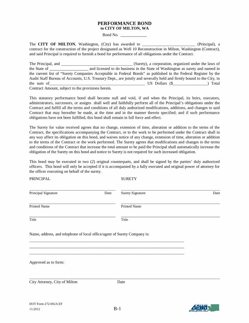
PERFORMANCE BONDto CITY OF MILTON, WABond No. _____________
The CITY OF MILTON, Washington, (City) has awarded to __________________________ (Principal), acontract for the construction of the project designated as Well 10 Reconstruction in Milton, Washington (Contract),and said Principal is required to furnish a bond for performance of all obligations under the Contract.
The Principal, and ___________________________________ (Surety), a corporation, organized under the laws ofthe State of ___________________ and licensed to do business in the State of Washington as surety and named inthe current list of “Surety Companies Acceptable in Federal Bonds” as published in the Federal Register by theAudit Staff Bureau of Accounts, U.S. Treasury Dept., are jointly and severally held and firmly bound to the City, inthe sum of_______________________________________________ US Dollars ($_________________) TotalContract Amount, subject to the provisions herein.
This statutory performance bond shall become null and void, if and when the Principal, its heirs, executors,administrators, successors, or assigns shall well and faithfully perform all of the Principal’s obligations under theContract and fulfill all the terms and conditions of all duly authorized modifications, additions, and changes to saidContract that may hereafter be made, at the time and in the manner therein specified; and if such performanceobligations have not been fulfilled, this bond shall remain in full force and effect.
The Surety for value received agrees that no change, extension of time, alteration or addition to the terms of theContract, the specifications accompanying the Contract, or to the work to be performed under the Contract shall inany way affect its obligation on this bond, and waives notice of any change, extension of time, alteration or additionto the terms of the Contract or the work performed. The Surety agrees that modifications and changes to the termsand conditions of the Contract that increase the total amount to be paid the Principal shall automatically increase theobligation of the Surety on this bond and notice to Surety is not required for such increased obligation.
This bond may be executed in two (2) original counterparts, and shall be signed by the parties’ duly authorizedofficers. This bond will only be accepted if it is accompanied by a fully executed and original power of attorney forthe officer executing on behalf of the surety.
PRINCIPAL SURETY
Principal Signature Date Surety Signature Date
Printed Name Printed Name
Title Title
Name, address, and telephone of local office/agent of Surety Company is:____________________________________________________________________________________________________________________________________________________________________________________________________________________________________
Approved as to form:
City Attorney, City of Milton Date

DOT Form 272-002A EF11/2012 B-2
PUBLIC WORKS PAYMENT BONDto CITY OF MILTON, WABond No. _____________
The CITY OF MILTON, Washington, (City) has awarded to __________________________ (Principal), acontract for the construction of the project designated as Well 10 Reconstruction in Milton, Washington (Contract),and said Principal is required under the terms of that Contract to furnish a payment bond in accord with Title 39.08Revised Code of Washington (RCW) and (where applicable) 60.28 RCW.
The Principal, and ___________________________________ (Surety), a corporation organized under the laws ofthe State of ___________________ and licensed to do business in the State of Washington as surety and named inthe current list of “Surety Companies Acceptable in Federal Bonds” as published in the Federal Register by theAudit Staff Bureau of Accounts, U.S. Treasury Dept., are jointly and severally held and firmly bound to the City, inthe sum of_______________________________________________ US Dollars ($_________________) TotalContract Amount, subject to the provisions herein.
This statutory payment bond shall become null and void, if and when the Principal, its heirs, executors,administrators, successors, or assigns shall pay all persons in accordance with RCW Titles 39.08 and 39.12including all workers, laborers, mechanics, subcontractors, and materialmen, and all persons who shall supply suchcontractor or subcontractor with provisions and supplies for the carrying on of such work; and if such paymentobligations have not been fulfilled, this bond shall remain in full force and effect.
The Surety for value received agrees that no change, extension of time, alteration or addition to the terms of theContract, the specifications accompanying the Contract, or to the work to be performed under the Contract shall inany way affect its obligation on this bond, except as provided herein, and waives notice of any change, extension oftime, alteration or addition to the terms of the Contract or the work performed. The Surety agrees that modificationsand changes to the terms and conditions of the Contract that increase the total amount to be paid the Principal shallautomatically increase the obligation of the Surety on this bond and notice to Surety is not required for suchincreased obligation.
This bond may be executed in two (2) original counterparts, and shall be signed by the parties’ duly authorizedofficers. This bond will only be accepted if it is accompanied by a fully executed and original power of attorney forthe officer executing on behalf of the surety.
PRINCIPAL SURETY
Principal Signature Date Surety Signature Date
Printed Name Printed Name
Title Title
Name, address, and telephone of local office/agent of Surety Company is:____________________________________________________________________________________________________________________________________________________________________________________________________________________________________
Approved as to form:
City Attorney, City of Milton Date

PART 3
GENERAL CONDITIONS

September 12, 2017 – General Conditions i
GENERAL CONDITIONS
TABLE OF CONTENTS PAGE
GENERAL INFORMATION APPLICABLE TO PROPOSAL ANDCONTRACT ......................................................................................................................... 1-1
1.01 DEFINITIONS AND TERMINOLOGY .................................................................. 1-11.02 ABBREVIATIONS AND TERMINOLOGY........................................................... 1-1
1.02.1 REFERENCED STANDARDS AND CODES ................................................. 1-11.02.2 TERMINOLOGY ............................................................................................ 1-31.02.3 ITEMS OF WORK AND UNITS OF MEASUREMENT................................. 1-3
1.03 DEFINITIONS ........................................................................................................ 1-4 INSTRUCTIONS FOR PREPARATION OF PROPOSAL (OR BID) ....... 2-1
2.01 BID PROCEDURES AND CONDITIONS .............................................................. 2-12.01.1 QUALIFICATIONS OF BIDDERS ................................................................. 2-12.01.2 CONTRACT PROVISIONS AND CONTRACT PLANS ................................ 2-12.01.3 ESTIMATED QUANTITIES ........................................................................... 2-12.01.4 EXAMINATION OF CONTRACT AND SITE ............................................... 2-1
2.01.4(1) General..................................................................................................... 2-12.01.4(2) Interpretation of the Contract Provisions and Contract Plans..................... 2-22.01.4(3) Subsurface Information ............................................................................ 2-22.01.4(4) Availability of Specified Items ................................................................. 2-3
2.01.5 PROPOSAL DEPOSIT .................................................................................... 2-32.01.6 PROPOSAL ..................................................................................................... 2-32.01.7 WITHDRAWING OR REVISING PROPOSAL .............................................. 2-52.01.8 DISQUALIFICATION OF BIDDERS ............................................................. 2-52.01.9 PROPOSAL ERRORS ..................................................................................... 2-7
2.02 AWARD AND EXECUTION OF CONTRACT ...................................................... 2-72.02.1 AWARD OF CONTRACT .............................................................................. 2-72.02.2 EXECUTION OF CONTRACT ....................................................................... 2-82.02.3 FAILURE TO EXECUTE CONTRACT .......................................................... 2-82.02.4 RETURN OF BID DEPOSIT ........................................................................... 2-82.02.5 NOTICE TO PROCEED .................................................................................. 2-8
GENERAL REQUIREMENTS OF THE CONTRACT .............................. 3-13.01 SCOPE OF THE WORK ......................................................................................... 3-1
3.01.1 INTENT OF THE CONTRACT....................................................................... 3-13.01.2 COORDINATION OF CONTRACT ............................................................... 3-13.01.3 ASSIGNMENT OF CONTRACT .................................................................... 3-1
3.02 CONTROL OF WORK ........................................................................................... 3-23.02.1 AUTHORITY AND ROLE OF THE ENGINEER ........................................... 3-23.02.2 AUTHORITY OF FIELD REPRESENTATIVE .............................................. 3-33.02.3 CONSTRUCTION OBSERVATION AND INSPECTIONS ............................ 3-43.02.4 EMERGENCY CONTACT LIST .................................................................... 3-53.02.5 ORAL AGREEMENTS ................................................................................... 3-5
3.03 LEGAL RELATIONS AND RESPONSIBILITIES ................................................. 3-5

September 12, 2017 – General Conditions ii
3.03.1 APPLICABLE LAWS AND REGULATIONS ................................................ 3-53.03.1(1) General..................................................................................................... 3-53.03.1(2) Utilities and Similar Facilities .................................................................. 3-53.03.1(3) Site Maintenance ...................................................................................... 3-63.03.1(4) State Taxes ............................................................................................... 3-63.03.1(5) Equal Employment Responsibilities ......................................................... 3-73.03.1(6) Archaeological and Historical Objects ...................................................... 3-8
3.03.2 SAFETY MEASURES .................................................................................... 3-83.03.3 HAZARDOUS MATERIAL ............................................................................ 3-83.03.4 PAYMENT OF WAGES AND RELATED REQUIREMENTS ....................... 3-9
3.03.4(1) Minimum Prevailing Wage Requirements ................................................ 3-93.03.4(2) Posting Notice Requirements ...................................................................3-103.03.4(3) Apprentices .............................................................................................3-103.03.4(4) Required Documents ...............................................................................3-11
3.03.5 BONDS, INSURANCE AND INDEMNITY OBLIGATIONS........................3-123.03.5(1) Contract Bonds ........................................................................................3-12
3.03.5(1.1) Two-Year Guarantee Period...........................................................3-133.03.5(2) Worker’s Benefits ...................................................................................3-133.03.5(4) Public Liability & Property Damage Insurance ........................................3-13
3.03.5(4.1) General Requirements ....................................................................3-133.03.5(4.2) Additional Insured .........................................................................3-143.03.5(4.3) Subcontractors ...............................................................................3-153.03.5(4.4) Verification of Coverage ................................................................3-153.03.5(4.5) Coverages and Limits ....................................................................3-15
3.03.5(4.5)A Commercial General Liability ..................................................3-163.03.5(4.5)B Automobile Liability ................................................................3-163.03.5(4.5)C Workers’ Compensation ...........................................................3-163.03.5(4.5)D Excess or Umbrella Liability ....................................................3-163.03.5(4.5)E Builders Risk Insurance ...........................................................3-173.03.5(4.5)F LHWCA Insurance ..................................................................3-173.03.5(4.5)G Protection and Indemnity Insurance Including Jones Act ..........3-183.03.5(4.5)H Hull and Machinery .................................................................3-18
3.03.5(5) Indemnity and Hold Harmless .................................................................3-183.03.5(6) Patent Royalties & Process Fees ..............................................................3-19
3.03.6 METHOD OF SERVING NOTICE ................................................................3-193.04 PROSECUTION AND PROGRESS OF THE WORK ............................................3-19
3.04.1 QUALITY OF WORK ....................................................................................3-193.04.1(1) Workmanship ..........................................................................................3-193.04.1(2) Contractor’s Supervisory and Site Personnel ...........................................3-20
3.04.2 MATERIALS AND EQUIPMENT .................................................................3-203.04.3 SPECIFICATION OF PARTICULAR MATERIALS AND EQUIPMENT .....3-213.04.4 STORAGE ......................................................................................................3-21
3.04.4(1) On-Site Storage .......................................................................................3-213.04.4(2) Off-Site Storage ......................................................................................3-22
3.04.5 DEFECTIVE MATERIALS, EQUIPMENT AND WORKMANSHIP ............3-223.04.6 CHANGES IN THE WORK ...........................................................................3-233.04.7 DIFFERING SITE CONDITIONS ..................................................................3-27
September 12, 2017 – General Conditions iii
3.04.8 PROTEST BY THE CONTRACTOR .............................................................3-283.04.9 SUBCONTRACTORS AND SUBCONTRACTS ...........................................3-29
3.04.9(1) Contractor Responsibility ........................................................................3-293.04.9(2) Contractor Work Performance Requirement ............................................3-303.04.9(3) Approval of Subcontractors .....................................................................3-303.04.9(4) Subcontracts ............................................................................................3-303.04.9(5) Incorporation of Contract ........................................................................3-303.04.9(6) Replacement of Subcontractors ...............................................................3-30
3.04.10 MUTUAL RESPONSIBILITY OF CONTRACTORS ....................................3-303.04.11 RISK OF LOSS ..............................................................................................3-313.04.12 MEASUREMENT AND PAYMENT .............................................................3-31
3.04.12(1) General ...................................................................................................3-313.04.12(2) Measurement ..........................................................................................3-313.04.12(3) Payment ..................................................................................................3-313.04.12(4) Access to Books and Records ..................................................................3-313.04.12(5) Progress Payment Estimates ....................................................................3-323.04.12(6) Payment for Materials on Hand ...............................................................3-323.04.12(7) Payments Withheld .................................................................................3-323.04.12(8) Payment Upon Correction of Deficiencies ...............................................3-333.04.12(9) Final Payment .........................................................................................3-33
3.04.13 WORK HOURS ..............................................................................................3-343.04.14 CONTRACT TIME ........................................................................................3-353.04.15 CONSTRUCTION SCHEDULE .....................................................................3-36
3.04.15(1) Progress Schedule ...................................................................................3-363.04.15(2) Extensions of the Contract Time .............................................................3-373.04.15(3) Liquidated Damages ...............................................................................3-38
3.04.16 COMPLETION AND ACCEPTANCE OF THE WORK ................................3-383.04.16(1) Substantial Completion Date ...................................................................3-383.04.16(2) Physical Completion Date .......................................................................3-393.04.16(3) Contract Completion Date (Acceptance of the Project) ............................3-403.04.16(4) Use of Completed Portions of the Work ..................................................3-413.04.16(5) Waiver of Claims by Contractor ..............................................................3-41
3.04.17 CORRECTION OF FAULTY WORK AFTER FINAL PAYMENT ...............3-413.04.18 RETAINAGE .................................................................................................3-41
3.05 DISPUTES AND CLAIMS ....................................................................................3-433.05.1 DISPUTES .....................................................................................................3-433.05.2 CLAIMS .........................................................................................................3-433.05.3 TIMELINE AND JURISDICTION .................................................................3-463.05.4 CONTINUATION OF WORK PENDING RESOLUTION OF DISPUTES ....3-46
3.06 AUDITS .................................................................................................................3-463.07 SUSPENSION OF WORK AND TERMINATION OF CONTRACT .....................3-47
3.07.1 SUSPENSION OF WORK..............................................................................3-473.07.2 TERMINATION FOR DEFAULT ..................................................................3-473.07.3 TERMINATION FOR CONVENIENCE OF THE OWNER ...........................3-483.07.4 RESPONSIBILITY OF THE CONTRACTOR AND SURETY ......................3-48

September 12, 2017 – General Conditions 1-1
GENERAL CONDITIONS
GENERAL INFORMATION APPLICABLETO PROPOSAL AND CONTRACT
1.01 DEFINITIONS AND TERMINOLOGY
The following terms are abbreviated and defined as they are used in the Contract. When used inthe Proposal form to denote items of Work and units of measurements, abbreviations mean the fullexpression of the abbreviated term.
1.02 ABBREVIATIONS AND TERMINOLOGY
1.02.1 REFERENCED STANDARDS AND CODES
The following is a partial list of specifications and codes that may be referenced in sections of theContract. The Contractor shall be responsible for conducting its Work and carrying out itsoperations and furnishing equipment in accordance with the latest edition or versions, in effect atthe time of bid opening, of any applicable specified portions of the referenced standards and codes.
AASHTO American Association of State Highway and Transportation OfficialsACI American Concrete InstituteAFBMA Anti-friction Bearing Manufacturing AssociationAGA American Gas AssociationAGC Associated General Contractors of AmericaAI Asphalt InstituteAIA American Institute of ArchitectsAISC American Institute of Steel ConstructionAISI American Iron and Steel InstituteAITC American Institute of Timber ConstructionAMCA Air Moving and Conditioning AssociationANLA American Nursery and Landscape AssociationANSI American National Standards Institute, Inc.APA American Plywood AssociationAPI American Petroleum InstituteAPWA American Public Works AssociationARA American Railway AssociationAREMA American Railway Engineering and Maintenance-of-Way AssociationASA American Standards AssociationASCE American Society of Civil EngineersASLA American Society of Landscape ArchitectsASME American Society Mechanical EngineersASNT American Society for Nondestructive TestingASTM American Society for Testing and MaterialAWPA American Wood Preservers’ AssociationAWS American Welding Society

September 12, 2017 – General Conditions 1-2
AWWA American Water Works AssociationCFR Code of Federal RegulationsCLI Chain Link InstituteCRAB County Road Administration BoardCRSI Concrete Reinforcing Steel InstituteCSA Canadian Standards AssociationsCSI Construction Specifications InstituteDIPRA Ductile Iron Pipe Research AssociationEEI Edison Electric InstituteEPA Environmental Protection AgencyETL Electrical Testing LaboratoriesFHWA Federal Highway AdministrationFM Factory MutualFSS Federal Specifications and Standards, General Services AdministrationHUD United State Department of Housing and Urban DevelopmentIBC International Building CodeICEA Insulated Cable Engineers AssociationIEEE Institute of Electrical and Electronic EngineersIES Illumination Engineering SocietyIMSA International Municipal Signal AssociationIPC International Plumbing CodeISA Instrumentation Society of AmericaJIC Joint Industry Conference Electrical Standards for Industrial EquipmentLID Local Improvement DistrictLPI Lightning Protection InstituteMSHA Mine Safety and Health ActMSS Manufacturer’s Standardization Society of the Valve and Fitting IndustryMUTCD Manual on Uniform Traffic Control DevicesNCMA National Concrete Manufacturer’s AssociationNEC National Electrical CodeNEMA National Electrical Manufacturers’ AssociationNEPA National Environmental Policy ActNFPA National Fire Protection AssociationNRMCA National Ready Mix Concrete AssociationOMWBE Office of Minority and Women’s Business EnterprisesOSHA Occupational Safety and Health AdministrationPCA Portland Cement AssociationPPI Plastic Pipe InstituteP/PCI Precast/Prestressed Concrete InstituteRCW Revised Code of WashingtonSAE Society of Automotive EngineersSEPA State Environmental Policy ActSIES Specifications and Illuminating Engineering SocietySSPC Steel Structures Painting CouncilUL Underwriters’ LaboratoryULID Utility Local Improvement DistrictUMTA Urban Mass Transit Administration

September 12, 2017 – General Conditions 1-3
WABO Washington Association of Building OfficialsWAC Washington Administrative CodeWCLIB West Coast Lumber Inspection BureauWISHA Washington Industrial Safety and Health AdministrationWRI Wire Reinforcement InstituteWSDL&I Washington State Department of Labor and IndustriesWSDOE Washington State Department of EcologyWSDOT Washington State Department of TransportationWWPA Western Wood Products Association
1.02.2 TERMINOLOGY
The use of pronouns of any gender in these General Conditions shall include pronouns of allgenders, as applicable.
The terms “provide,” “furnish” and “install” are used interchangeably in the Contract and meanthat the Contractor shall provide, furnish, and install the item(s) described unless specifically notedotherwise.
The terms “Plans” and “Drawings” are used interchangeably in the Contract and shall mean theContract Plans, which show location, character, and dimensions of prescribed Work, includinglayouts, profiles, cross-sections, and other details.
1.02.3 ITEMS OF WORK AND UNITS OF MEASUREMENT
AC Asbestos Cement PipeAgg. AggregateAl. AluminumATB Asphalt Treated BaseBST Bituminous Surface TreatmentCB Catch BasinCfm Cubic Feet per MinuteCfs Cubic Feet per SecondCl. ClassCMP Corrugated Metal PipeComb. CombinationConc. ConcreteCPEP Corrugated Polyethylene PipeCrib. CribbingCulv. CulvertCy or Cu. Yd. Cubic Yard(s)Dia. DiameterDI Ductile IronDIM DimensionEA EachEL ElevationEst. Estimate or Estimated
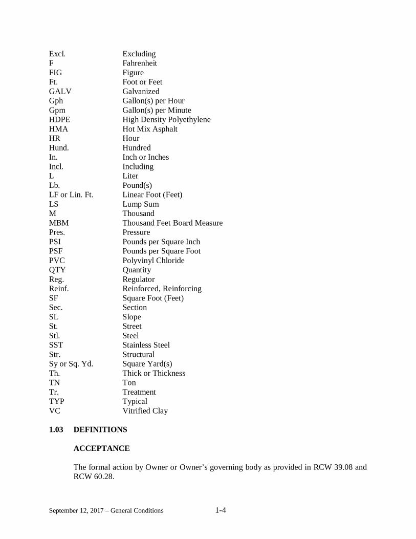
September 12, 2017 – General Conditions 1-4
Excl. ExcludingF FahrenheitFIG FigureFt. Foot or FeetGALV GalvanizedGph Gallon(s) per HourGpm Gallon(s) per MinuteHDPE High Density PolyethyleneHMA Hot Mix AsphaltHR HourHund. HundredIn. Inch or InchesIncl. IncludingL LiterLb. Pound(s)LF or Lin. Ft. Linear Foot (Feet)LS Lump SumM ThousandMBM Thousand Feet Board MeasurePres. PressurePSI Pounds per Square InchPSF Pounds per Square FootPVC Polyvinyl ChlorideQTY QuantityReg. RegulatorReinf. Reinforced, ReinforcingSF Square Foot (Feet)Sec. SectionSL SlopeSt. StreetStl. SteelSST Stainless SteelStr. StructuralSy or Sq. Yd. Square Yard(s)Th. Thick or ThicknessTN TonTr. TreatmentTYP TypicalVC Vitrified Clay
1.03 DEFINITIONS
ACCEPTANCE
The formal action by Owner or Owner’s governing body as provided in RCW 39.08 andRCW 60.28.

September 12, 2017 – General Conditions 1-5
ADDENDUM
A written or graphic document issued to all Bidders prior to bid opening and identified asan addendum, which clarifies, modifies or supplements the bid documents and becomespart of the Contract.
ADDITIVE
A supplemental unit of work or group of bid items, identified separately in the Proposal,which may, at the discretion of the Owner, be awarded in addition to the base bid.
ALTERNATE
One of two or more units of work or groups of bid items, identified separately in theProposal, from which the Owner may make a choice between different methods or materialof construction for performing the same work.
AWARD
The formal decision of the Owner awarding the Contract to the lowest or most favorableresponsible and responsive Bidder for the Work.
BID DOCUMENTS
The component parts of the proposed Contract which may include, but not limited to, theProposal form, the proposed Contract Provisions, the proposed Contract Plans, Addenda,and Subsurface Boring Logs (if any).
BIDDER
A natural person or legal entity (e.g., partnership, corporation, limited liability company,firm, or joint venture) submitting a proposal or bid.
BUSINESS DAY
A business day is any day from Monday through Friday, except holidays, as listed inSection 3.04.14.
CLERK
The duly elected or appointed Clerk of the Commission, Council, or Board of Directors ofthe Owner.
COMMISSION, COUNCIL, OR BOARD OF DIRECTORS
The duly elected or appointed Council, Commission, or Board of Directors of the Owner.
September 12, 2017 – General Conditions 1-6
CONTRACT
The written agreement between the Owner and the Contractor. It describes, among otherthings:
1. What work will be done, and by when;2. Who will provide labor and materials; and3. How Contractor will be paid.
The Contract includes: the agreement form, Bidder’s completed Proposal form, all requiredcertificates and affidavits, Performance Bond and Public Works Payment Bond, ContractProvisions, Contract Plans, Standard Plans, and all Addenda and Change Orders executedpursuant to the provisions of the Contract.
CONTRACT BOND
The approved form of security furnished by the Contractor and the Contractor’s Surety asrequired by the Contract, that guarantees performance of all the Work required by theContract and payment to anyone who provides supplies or labor for the performance ofthe Work.
CONTRACT DOCUMENTS
See definition for “Contract.”
CONTRACT PLANS (PLANS OR DRAWINGS)
The Contract Plans (or drawings) are those plans, drawings or other illustrations and alladdenda and revisions, whether issued before or after the award of the contract toContractor, which show location, character, and dimensions of the Work, includinglayouts, profiles, cross-sections and other details.
CONTRACT PROVISIONS
A publication addressing the work required for an individual project. At the time of thecall for bids, the contract provisions may include, for a specific individual project, generalconditions, supplemental general conditions, specifications, a listing of the applicablestandard plans, the prevailing minimum hourly wage rates, and an informational proposalform with the listing of bid items. The proposed contract provisions may also include, fora specific individual project, various required certifications or declarations. At the time ofthe contract execution date, the contract provisions include the proposed contractprovisions and include any addenda, a copy of the agreement form, and a copy of theproposal form with the contract prices and extensions.

September 12, 2017 – General Conditions 1-7
CONTRACT TIME
The period of time established by the terms and conditions of the Contract within whichthe work shall be complete.
CONTRACTOR
The natural person(s) or legal entity (e.g., partnership, corporation, limited liabilitycompany, firm, joint venture) awarded the contract to perform the Work pursuant to theContract Documents.
DATES
Substantial Completion Date is the day that the Engineer determines the Owner has fulland unrestricted use and benefit of the Work, from both an operational and safetystandpoint, any remaining traffic disruptions will be rare and brief, and only minorincidental work, replacement of temporary substitute facilities, plant establishment periods,or correction or repair remains for the physical completion of the total Work.
Physical Completion Date is the day that the Engineer determines that all of the Workrequired by the Contract is physically completed and the Owner has received from theContractor all required record drawings, operation and maintenance manuals,manufacturers’ affidavits, and software and programming.
Contract Completion Date is the day when all the Work and all the obligations of theContractor under the Contract are fulfilled by the Contractor. All documentation and otheritems required by the Contract and required by law shall be furnished by the Contractorbefore establishment of this date.
Final Acceptance Date is the date on which the Owner accepts the work as complete.
FIELD REPRESENTATIVE
The Owner’s representative who observes the Contractor’s performance of the Work. Suchobservation shall not be relied upon by the Contractor or others as approval or acceptanceof the Work, nor shall it in any manner relieve the Contractor from its obligations andresponsibilities under the Contract.
NOTICE TO PROCEED
The written notice from the Owner or Engineer to the Contractor authorizing and directingthe Contractor to proceed with the Work and establishing the date on which the ContractTime begins.

September 12, 2017 – General Conditions 1-8
OWNER
The government entity or agency that awards the contract to the Contractor and isresponsible for the execution and administration of the Contract.
PROJECT ENGINEER/ENGINEER
The Owner’s representative who administers the construction program for the Owner.
PROPOSAL (or BID)
A Bidder’s offer, on a properly completed Proposal form, to perform the Work required bythe Contract. The terms Proposal and Bid may be used interchangeably.
SPECIFICATIONS
Written provisions describing the Work and requirements thereof.
STANDARD PLANS
A manual of specific plans or drawings adopted by the Owner, which show frequentlyrecurring components of work that, have been standardized for use.
SUBCONTRACTOR
A natural person, or entity (e.g., partnership, corporation, limited liability company, firmor joint venture) to which the Contractor sublets a portion of the Work.
SUBGRADE
The top surface of the roadbed on which subbase, base, surfacing, pavement, or layers ofsimilar materials are placed.
SUPPLEMENTARY GENERAL CONDITIONS
That part of the Contract amends or supplements these General Conditions.
TRAVELED WAY
That part of the roadway made for vehicle travel, excluding shoulders and auxiliary lanes.
WORK
The provision of all labor, materials, tools, equipment, supervision and other things neededto complete the project in full accordance with the Contract Documents.

September 12, 2017 – General Conditions 1-9
WORKING DRAWINGS
Shop drawings, shop plans, erection plans, falsework plans, framework plans, cofferdam,cribbing and shoring plans, bending diagrams for reinforcing steel, or any othersupplementary plans or similar data, including a schedule of submittal dates for workingdrawings where specified, that the Contractor shall submit to the Engineer for approval.

September 12, 2017 – General Conditions 2-1
INSTRUCTIONS FOR PREPARATION OF PROPOSAL (OR BID)
2.01 BID PROCEDURES AND CONDITIONS
2.01.1 QUALIFICATIONS OF BIDDERS
Where applicable and required, Bidders shall provide all requested information relating toexperience, financing, equipment, and organization relating to their ability to properly perform theWork. The Owner reserves the right to take whatever action it deems necessary to ascertain theresponsibility of the Bidder and the ability of the Bidder to perform the Work satisfactorily.
2.01.2 CONTRACT PROVISIONS AND CONTRACT PLANS
Contract Provisions and Contract Plans are on file in the offices of the Owner and the Engineer,Gray & Osborne, Inc. After award of the Contract, five sets of Contracts will be issued withoutcharge to the Contractor. Additional sets of Contracts may be purchased from the Owner by theContractor.
2.01.3 ESTIMATED QUANTITIES
The quantities shown in the Proposal form are estimates and are stated only for bid comparisonpurposes. The Owner does not warrant, expressly or by implication, that the actual quantities willcorrespond with those estimates. Payment will be made on the basis of the actual quantities ofeach item of Work satisfactorily completed in accordance with the requirements of the Contract.
2.01.4 EXAMINATION OF CONTRACT AND SITE
2.01.4(1) General
Bidders shall satisfy themselves by personal examination of Contract Provisions, Contract Plans,and site of the proposed improvements, and by any other examination and investigation which theymay desire to make as to the accuracy of the estimate of quantities, the nature of the Work and thedifficulties to be encountered. Bidders shall review the entire Contract to ensure that thecompleteness of their Proposal includes all items of Work regardless of where shown in theContract. Bidders are cautioned that alternate sources of information (copies of the Contractobtained from third parties) are not necessarily an accurate or complete representation of theContract. Bidders shall use such information at their own risk.
Bidders shall be familiar and comply with all applicable federal, state, and local laws, ordinances,and regulations in any way applicable to the performance the Work. Bidders are responsible forfamiliarizing themselves with all current state and federal wage rates applicable to the Work andits duration before submitting a Proposal based on the Contract Provisions and Contract Plans.Any wage determination contained in the Contract is for the Bidder’s general information onlyand is not warranted to be complete or accurate. The Owner will not consider any plea ofmisunderstanding or ignorance of such requirements. Bid prices shall reflect what the Bidder hasdetermined to be the total cost of completing the Work, including but not limited to: constructionmethods, materials, labor, administrative costs, any and all applicable taxes, and equipment.
September 12, 2017 – General Conditions 2-2
Except as the Contract may provide, the Bidder to which the contract is awarded shall receive nopayment for any costs that exceed those set forth in the Proposal.
2.01.4(2) Interpretation of the Contract Provisions and Contract Plans
If any Bidder desires interpretation or clarification of the Contract Provisions and Contract Plans,the Bidder shall make a written request to the Engineer for such clarification or interpretation priorto the submission of a Proposal. If the Engineer determines that the Contract Provisions and/orContract Plans do not require interpretation or clarification, the Engineer will so notify the Biddermaking the request. All interpretations and clarifications made by the Engineer will be by writtenaddendum to all planholders of record, and a copy of the addendum will be filed in the office ofthe Owner. Neither the Owner nor the Engineer will be responsible for any interpretation,clarification or explanation of the Contract Provisions and Contract Plans that is not set forth in awritten addendum to all planholders of record, and Bidders shall not under any circumstances relyon any other interpretation, clarification or explanation.
2.01.4(3) Subsurface Information
If the Owner has made a subsurface investigation of the site of the proposed Work, the boring logdata and soil sample test data accumulated by the Owner will be made available for inspection bythe Bidders. However, the Owner makes no representation or warranty, express or implied, that:
a. The Bidders’ interpretations from the boring logs may be correct;
b. Moisture conditions and indicated water tables will not vary from those found atthe time the borings were made;
c. The ground at the location of the borings has not been physically disturbed oraltered after the boring was made; and
d. Conditions below the surface of the ground are consistent throughout the site withthe information made available hereunder, or that conditions to be encountered onthe site are uniform or consistent with geological conditions usually encountered inthe area.
The Owner makes no representations, guarantees, or warranties as to the condition, materials, orproportions of the materials between the specific borings, regardless of any subsurface informationthe Owner may make available to the prospective Bidders. Bidders are solely responsible formaking the necessary investigations to support and/or verify any conclusions or assumptions usedin preparation of their Proposals.
Any subsurface investigations and analysis were carried out for design purposes only.Contractor may not rely upon or make any claim against Owner, Engineer, or any of theirsubconsultants, with respect to:
1. The completeness of such reports for Contractor’s purposes, including, but notlimited to, any aspects of the means, methods, techniques, sequences, and

September 12, 2017 – General Conditions 2-3
procedures of construction to be employed by Contractor, and safety precautionsand programs incident thereto; or
2. Other conclusions, interpretations, opinions, representations, and informationcontained in such reports; or
3. Any Contractor interpretation of or conclusion drawn from any “technical data”or any such other data, conclusions, interpretations, opinions or information.
2.01.4(4) Availability of Specified Items
Prior to submitting a Proposal, all Bidders shall verify that all items necessary to complete theWork will be available in time to allow the Work to be completed within the Contract Time. Inthe event that one or more items may not be available to allow the Work to be completed withinthe Contract Time, the Bidder shall notify the Engineer in writing prior to submitting a Proposal.Responsibility for delays and related costs because of non-availability of items necessary tocomplete the Work shall be borne by the Contractor.
2.01.5 PROPOSAL DEPOSIT
A deposit of at least 5 percent of the total Proposal amount shall accompany each Proposal. Thisdeposit may be in the form of a Proposal bond (surety bond), certified check, cashier’s check, orpostal money order made payable to the Owner. All Proposal bonds shall be on the form includedwithin the Contract Provisions and shall be signed by the Bidder and the surety. The surety shall:(1) be registered with the Washington State Commissioner, and (2) appear on the currentAuthorized Insurance List in the State of Washington published by the Office of the InsuranceCommissioner. The Proposal bond shall not be conditioned in any way to modify the minimum5 percent required. The Proposal Deposit will be held as a guaranty that the successful Bidderwill, within 10 days from the date of notification of Award, enter into a Contract and furnishapproved Performance and Public Works Payment Bonds, on forms attached, in amounts equal to100 percent of the amount of the Contract, including state sales tax.
2.01.6 PROPOSAL
(1) Proposals shall be submitted on the Proposal form included in the ContractProvisions. All Proposals shall be completed, signed by an authorized person anddated. To be considered by the Owner as a responsive Proposal, the Bidder shallbid on all Additive or Alternate items set forth in the Proposal form, unlessotherwise specified in the Contract Documents.
(2) To be responsive, a Proposal shall state that it will remain valid for a period of60 days following the date of Proposal opening. In the event that a conflict in thisduration appears elsewhere in the Contract Provisions, the longest duration shallapply.
(3) All prices set forth on the Proposal form shall be legible and either be written in inkor typed. In the space provided on the Proposal form, Bidders shall identify all

September 12, 2017 – General Conditions 2-4
Addenda that have been received. The Proposal, Bid bond, and all othercertificates, forms or other documents required by the Contract Provisions to beexecuted and delivered with the Proposal shall be submitted in a sealed package,addressed to the Owner, and plainly marked “Proposal for ______________ (insertname of project as shown on the Proposal) to be opened on the ______ day of____________, 20___,” (insert the day, month and year shown in the published bidnotice). The Owner will not consider any Proposal received after the timeestablished for opening Proposals.
(4) Where noted in the Proposal, the Bidder to furnish information concerning itsexperience with work of a similar nature, equipment to be used on this project, andgeneral background information. Information that is incomplete, evasive, or of ageneral nature only, may be considered as grounds for rejection of the Proposal.
(5) RCW 39.30.060 requires Bidders on public works projects expected to cost onemillion dollars or more to provide the names of the heating, ventilation and airconditioning, plumbing and electrical Subcontractors to whom the Bidder willdirectly subcontract those portions of the Work if awarded the contract. The Biddermay not list more than one Subcontractor for each category of Work identified,unless Subcontractors vary with bid alternates, in which case the Bidder shallindicate which Subcontractor will be used for which alternate. Failure of the Bidderto list the names of such Subcontractors or to name itself to perform such Work, orlisting two or more Subcontractors to perform the same Work, shall render theBidder’s Proposal unresponsive and void. Under RCW 39.30.060, the requirednames of such Subcontractors shall be provided with the Proposal or within onehour after the published Proposal submittal time. In addition to compliance withthe requirements of RCW 39.30.060, the apparent successful Bidder may berequired to submit to the Engineer as soon as possible after the Proposal opening,and not later than three calendar days thereafter, a written list of all proposedSubcontractors in addition to heating, ventilation, and air conditioning, plumbingand electrical contractors, that will perform subcontracting Work on the Project. Ifnot previously provided, the following information shall be provided for eachSubcontractor:
a. Name, address, email address, facsimile number, telephone number,contractor registration number and certification numbers;
b. The type of Work to be performed;
c. A list of at least three recently completed projects for Work similarto that to be performed by the proposed Subcontractor, with thefollowing information for each project:
i. Name of project,
ii. Name, address, and telephone number of the project owner;and

September 12, 2017 – General Conditions 2-5
d. Any additional pertinent information establishing the experience orqualifications of the proposed Subcontractor.
(6) After opening and reading Proposals, the Owner will check them for correctness ofextensions of the prices per unit and the total price. If a discrepancy exists betweenthe price per unit and the extended amount of any bid item, the price per unit,converted to the actual extension, will control. The total extensions, correctedwhere necessary, will be used by the Owner for comparison and award purposesand to establish the amount of the Contractor’s Performance and Public WorksPayment Bonds.
2.01.7 WITHDRAWING OR REVISING PROPOSAL
After submitting a physical Proposal to the Owner, the Bidder may withdraw, or revise it if:
1. The Bidder submits a written request signed by an authorized person and physicallydelivers it to the place designated for receipt of Proposals, and
2. The Owner receives the request before the time set for receipt of Proposals, and3. The revised or supplemented Proposal (if any) is received by the Owner before the time set
for receipt of Proposals.
If the Bidder’s request to withdraw or revise its Proposal is received before the time set for receiptof Proposals, the Owner will return the unopened Proposal package to the Bidder. The Biddermust then submit the revised package in its entirety. If the Bidder does not submit a revisedpackage, then its bid shall be considered withdrawn.
Late revised Proposals or late withdrawal requests will be date recorded by the Owner and returnedunopened. Mailed, emailed, or faxed requests to withdraw or revise a Bid Proposal are notacceptable.
2.01.8 DISQUALIFICATION OF BIDDERS
1. A proposal will be considered irregular and will be rejected if:
a. The Bidder is not prequalified when so required;b. The authorized proposal form furnished by the Owner is not used or is
altered;c. The completed proposal form contains any unauthorized additions,
deletions, alternate Bids, or conditions;d. The Bidder adds provisions reserving the right to reject or accept the award,
or enter into the Contract;e. A price per unit cannot be determined from the Bid Proposal;f. The Proposal form is not properly executed;g. The Bidder fails to submit or properly complete a Subcontractor list, if
applicable;
September 12, 2017 – General Conditions 2-6
h. The Bidder fails to submit or properly complete a Disadvantaged, Minorityor Women’s Business Enterprise Certification, if applicable;
i. The Bid Proposal does not constitute a definite and unqualified offer to meetthe material terms of the Bid invitation; or
j. More than one proposal is submitted for the same project from a Bidderunder the same or different names.
2. A Proposal may be considered irregular and may be rejected if:
a. The Proposal does not include a unit price for every Bid item;b. Any of the unit prices are excessively unbalanced (either above or below
the amount of a reasonable Bid) to the potential detriment of the ContractingAgency;
c. Receipt of Addenda is not acknowledged;d. A member of a joint venture or partnership and the joint venture or
partnership submit Proposals for the same project (in such an instance, bothBids may be rejected); or
e. If Proposal form entries are not made in ink.
A Bidder will be deemed not responsible if:
1. The Bidder does not meet the mandatory bidder responsibility criteria inRCW 39.04.350(1); or
2. Evidence of collusion exists with any other Bidder or potential Bidder. Participantsin collusion will be restricted from submitting further bids; or
3. The Bidder, in the opinion of the Owner, does not have the means or thequalifications to complete the Work; or
4. An unsatisfactory performance record exists based on past or current Owner workor for work done for others, as judged from the standpoint of conduct of the work;workmanship; or progress; affirmative action; equal employment opportunitypractices; termination for cause; or Disadvantaged Business Enterprise, MinorityBusiness Enterprise, or Women’s Business Enterprise utilization; or
5. There is uncompleted work (Owner or otherwise), which in the opinion of theOwner might hinder or prevent the prompt completion of the work bid upon; or
6. The Bidder failed to settle bills for labor or materials on past or current contracts,unless there are extenuating circumstances acceptable to the Owner; or
7. The Bidder has failed to complete a written public contract or has been convictedof a crime arising from a previous public contract, unless there are extenuatingcircumstances acceptable to the Owner; or
8. The Bidder is unable, financially or otherwise, to perform the work, in the opinionof the Owner; or
9. There are any other reasons deemed proper by the Owner.
The basis for evaluation of Bidder compliance with these mandatory and supplemental criteriashall be any documents or facts obtained by Owner (whether from the Bidder or third parties)which any reasonable owner would rely on for determining such compliance, including but notlimited to: (1) financial, historical, or operational data from the Bidder; (2) information obtained

September 12, 2017 – General Conditions 2-7
directly by the Owner from owners for whom the Bidder has worked, or other public agencies orprivate enterprises; and (3) any additional information obtained by the Owner which is believed tobe relevant to the matter.
If the Owner determines the Bidder does not meet the bidder responsibility criteria above and istherefore not a responsible Bidder, the Owner shall notify the Bidder in writing, with the reasonsfor its determination. If the Bidder disagrees with this determination, it may appeal thedetermination within 48 hours of receipt of the Owner’s determination by presenting its appeal inwriting to the Owner. The Owner will consider the appeal before issuing its final determination.If the final determination affirms that the Bidder is not responsible, the Owner will not execute acontract with any other Bidder until at least two business days after the Bidder determined to benot responsible has received the final determination.
2.01.9 PROPOSAL ERRORS
If a Bidder discovers an error in the Bidder’s Proposal after the Proposals have been opened andtabulated and desires to withdraw the erroneous Proposal, the Bidder shall submit a notarizedaffidavit signed by the Bidder, accompanied by original certified worksheets used in thepreparation of the Proposal, requesting relief from the Award. The affidavit shall describe thespecific error(s) and certify that the worksheets are the originals used in the preparation of theProposal.
The affidavit and the certified worksheets shall be received by the Engineer before 5:00 p.m. localtime on the next business day following the day of the Proposal opening or the claim of error willnot be considered. The Engineer will review the certified worksheets to determine the validity ofthe claimed error, and make its recommendation to the Owner. If the Owner and Engineer concurthat the claim of error is allowable under applicable law, the Bidder will be relieved ofresponsibility for the Proposal, and the Proposal Deposit will be returned to the Bidder. Thereafter,at the discretion of the Owner, all Proposals may be rejected or an Award made to the next lowestresponsive, responsible Bidder.
2.02 AWARD AND EXECUTION OF CONTRACT
2.02.1 AWARD OF CONTRACT
A Contract will not be awarded until the Owner is satisfied that the successful Bidder isresponsible, reasonably familiar with the Work to be performed and has the necessary capital,tools, personnel and equipment to satisfactorily perform the Work.
The Owner reserves the right to waive informalities in the bidding, accept a Proposal of the lowestresponsive, responsible Bidder, reject any or all Proposals, republish the call for Proposals, orrevise or cancel the project.
After the date and hour set for the opening of the Proposals, no Bidder may withdraw its Proposalunless the Award of the Contract is delayed for a period exceeding 60 calendar days followingProposal opening. In the event that a conflicting duration appears elsewhere in the Invitation forProposals or Contract Provisions or advertisement, the longer period shall govern.

September 12, 2017 – General Conditions 2-8
2.02.2 EXECUTION OF CONTRACT
Within 10 calendar days after notification by the Owner of the Award, the successful Bidder shallreturn to the Engineer the signed Owner-prepared Contract, all insurance certificates andendorsements required by the Contract Provisions, all other certificates, information, and formsrequired by the Contract Provisions, and Performance and Public Works Payment Bonds requiredby the Contract Provisions. If the Contract is signed by an officer, agent, or other authorizedrepresentative of the Contractor, the officer, agent, or other representative shall furnish satisfactoryevidence of authority to sign as the legal representative of the Contractor, if required by the Owner.An authorized partner of a joint venture may sign the Contract, subject to the approval of theOwner, which may, at its discretion, require each and every member of the joint venture to signthe Contract.
Should the successful bidder fail to return to the Engineer the signed Owner-prepared Contract, allinsurance certificates and endorsements required by the Contract Provisions, all othercertifications, information, and forms required by the Contract Provisions, and Performance andPublic Works Payment Bonds required by the Contract Provisions within 10 calendar days afternotification by the Owner of the Award, the Owner reserves the right to and may elect to withdrawthe award to the successful bidder and award the Contract to the next responsible, responsivebidder.
Until the Owner executes the Contract, no Proposal shall bind the Owner, and the Contractor shallnot commence any Work. The Contractor shall bear all risks for any Work begun before theContract is executed by the Owner.
2.02.3 FAILURE TO EXECUTE CONTRACT
If the Contractor fails to submit the insurance certificates, bonds, and all other certificates, forms,information and documents as required by the Contract Provisions, with the executed Contractwithin the time required by the Contract Provisions, the Owner may then award the Contract tothe next lowest responsive, responsible Bidder or reject any or all Proposals.
2.02.4 RETURN OF BID DEPOSIT
When Proposals have been examined and corrected as necessary, proposal bonds and depositsaccompanying Proposals ineligible for further consideration will be returned. All other Proposalbonds and deposits will be held until the Contract is awarded and fully executed, after which theProposal bonds and deposits, except those subject to forfeiture, will be returned.
2.02.5 NOTICE TO PROCEED
A written Notice to Proceed will be issued to the Contractor by the Owner or Engineer after theContract has been executed by the Contractor and the Owner, and the Performance and PublicWorks Payment Bonds and required insurance and other certificates and documents are approvedby the Owner and, when applicable, by State or Federal agencies responsible for funding any

September 12, 2017 – General Conditions 2-9
portion of the project. The Contractor shall not commence Work until the Notice to Proceed hasbeen issued.

September 12, 2017 – General Conditions 3-1
GENERAL REQUIREMENTS OF THE CONTRACT
3.01 SCOPE OF THE WORK
3.01.1 INTENT OF THE CONTRACT
The intent of the Contract is to describe a functionally complete project to be constructed inaccordance with the Contract. The Contractor shall provide all labor, supervision, materials, tools,equipment, transportation, supplies, and other things required expressly by, or reasonably impliedfrom, the Contract, to complete all Work. Omissions from the Contract of details of Work whichare necessary to carry out the intent of the Contract, or which are customarily performed, shall notrelieve the Contractor from performing the complete Work called for by the Contract; such Workshall be performed as if fully set forth and described in the Contract. The unit or other bid pricesshall be full payment for everything required to complete the Work, including but not limited tolabor, supervision, materials, equipment, jobsite and home office overhead and profit.
3.01.2 COORDINATION OF CONTRACT
The Contract Plans and the Contract Provisions for the Work shall be considered as a whole, andanything shown or called for in one and omitted in any other is as binding as if called for or shownon both. Figure dimensions shall, in all cases, be used in preference to scale dimensions. Anyinconsistency in the Contract Documents shall be resolved by the following order of precedence(e.g., 1 presiding over 2 through 4, 2 presiding over 3 through 4, etc.):
1. Addenda;
2. The Agreement and Proposal Form;
3. Specifications;
3a. Supplementary General Conditions (including conditions supplied by federal orstate agencies on projects funded, in whole or part, by such agencies. In the eventof a conflict in various forms of General Conditions, those conditions affording thegreatest benefit or protection to the Owner shall govern.);
3b. General Conditions;
3c. Technical Specifications;
4. Contract Plans.
3.01.3 ASSIGNMENT OF CONTRACT
The Contractor shall not assign the Contract or any part of the Contract or of the funds to bereceived under the Contract unless such assignment is approved by the Owner and the Contractor’sPerformance and Public Works Payment Bonds surety prior to the execution or effectiveness ofthe assignment.

September 12, 2017 – General Conditions 3-2
3.02 CONTROL OF WORK
3.02.1 AUTHORITY AND ROLE OF THE ENGINEER
(1) The Engineer is the authorized representative of the Owner, and is employed to actas advisor and consultant to the Owner in engineering matters relating to theContract. Among other things, the Engineer may determine the quantity of materialinstalled or work completed, evaluate whether materials and equipment complywith the Specifications, and assist the Owner with answering questions relating tothe meaning and intent of the Contract. The Owner, with the advice of the Engineer,will make the final determination relating to quality, acceptability and conformityof labor and materials to the requirements of the Contract.
(2) The Engineer does not purport to be a safety expert, and is not engaged in thatcapacity under the Contract or the Engineer’s contract with the Owner. TheEngineer does not have either the authority or the responsibility to enforceconstruction safety laws, rules, regulations or procedures, or to order the stoppageof Work for claimed violations thereof. From time to time, the Engineer mayinform the Contractor of conditions that may constitute safety issues or violations.Such information will be provided solely to cooperate with and assist the Contractorand shall not make the Field Representative or the Engineer responsible for theenforcement of safety laws, rules, regulations or procedures. After receivinginformation relating to safety issues from the Engineer, the Contractor shall makeits own examination and analysis of the situation reported and take such action, ifany, that the Contractor determines to be appropriate. The Engineer’s performanceof project representation and observation services shall not make the Engineerresponsible for the enforcement of safety laws, rules, regulations or procedures; norshall it make the Engineer responsible for construction means, methods, techniques,sequences, or procedures, or for the Contractor’s failure to properly perform theWork, all of which are entirely the responsibility of the Contractor.
(3) The Engineer shall have no liability whatsoever to, or contractual relationship with,the Contractor in any way relating to the Contract. The Owner and the Contractorshall look solely to each other for the enforcement with respect to any rights,obligations, claims or liabilities arising under or in any way relating to the Contract.Neither the authority given to the Engineer herein, nor any action or serviceprovided by the Engineer or its subconsultants with regard to the Project, shallcreate any duty owed by the Engineer or its subconsultants to the Contractor or acause of action against the Engineer or its subconsultants by Contractor.
(4) Nothing in the Contract shall, in any way, be construed to place responsibility onthe Field Representative, Engineer or the Owner for the method, manner, directionor superintendency of the performance of the Work by the Contractor. Suchresponsibility rests solely with the Contractor.
September 12, 2017 – General Conditions 3-3
(5) Neither the Engineer nor any of its assistants or agents shall have any power towaive any obligation of the Contract. The Engineer’s failure to reject Work that isdefective or otherwise does not comply with the requirements of the Contract shallnot constitute approval or acceptance of the Work or relieve the Contractor of itsobligations under the Contract, notwithstanding that such Work have beenestimated for payment or that payments have been made for that Work. Neithershall such failure to reject Work, nor any acceptance by the Engineer or by theOwner of any part or of the whole of the Work bar a claim by the Owner at anysubsequent time for recovery of damages for the cost of removal and replacementof any portions of the Work that do not comply with the Contract.
(6) No order, measurement, determination or certificate by the Engineer or Owner forpayment of money or payment for or acceptance of the whole or of any part of theWork by the Engineer or the Owner or extension of time or possession taken by theOwner shall constitute a waiver of any portion of the Contract, nor shall any waiverof any breach of the Contract constitute a waiver of any other or subsequent breachthereof.
3.02.2 AUTHORITY OF FIELD REPRESENTATIVE
(1) Field Representatives are assigned to the project site to keep the Engineer andOwner generally informed as to the progress of the Work and the manner in whichit is being done; to keep records; and to act as liaison between the Contractor,Owner and Engineer. When observed, the Field Representative shall call theattention of the Contractor to any deviations from the Contract. However, failureof the Field Representative to call the attention of the Contractor to faulty Work ordeviations from the Contract shall not constitute either a waiver of any requirementin the Contract or acceptance of said Work.
(2) Since one of the Field Representative’s primary responsibilities is to observe thatthe Work progresses expediently and in a workmanlike manner, he or she may offersuggestions to the Contractor, which the Contractor, at its sole discretion, may ormay not choose to follow. Such suggestions are not to be considered as anythingbut suggestions offered to cooperate with and assist the Contractor and shall notconstitute an assumption of responsibility, financial or otherwise, by the FieldRepresentative, the Engineer or the Owner.
(3) The presence or absence of the Field Representative on the job site will be at thesole discretion of the Owner, and the presence or absence of the FieldRepresentative at any time will not relieve the Contractor of its responsibility toproperly perform the Work as required by the Contract.
(4) The Field Representative will have the authority, but not the obligation, to rejectdefective materials and equipment if observed; however, the failure of the FieldRepresentative to reject defective materials and equipment or any other Workinvolving deviations from the Contract will not constitute acceptance of such Work.The Field Representative is not authorized to approve or accept any portion of the

September 12, 2017 – General Conditions 3-4
Work or to issue instructions contrary to the Contract; all such approvals,acceptances or instructions shall be in writing and signed by the Engineer or theOwner.
(5) The Field Representative does not purport to be a safety expert, and is not engagedin that capacity under the Contract or the Engineer’s contract with the Owner. TheField Representative does not have either the authority or the responsibility toenforce construction safety laws, rules, regulations or procedures, or to order thestoppage of Work for claimed violations thereof. From time to time, the FieldRepresentative may inform the Contractor of conditions that may constitute safetyissues or violations. Such information will be provided solely to cooperate withand assist the Contractor and shall not make the Field Representative or theEngineer responsible for the enforcement of safety laws, rules, regulations orprocedures. After receiving information relating to safety issues from the FieldRepresentative, the Contractor shall make its own examination and analysis of thesituation reported and take such action, if any, that the Contractor determines to beappropriate. The Field Representative’s performance of observation services shallnot make the Field Representative responsible for the enforcement of safety laws,rules, regulations or procedures; nor shall it make the Field Representativeresponsible for construction means, methods, techniques, sequences, or procedures,or for the Contractor’s failure to properly perform the Work, all of which areentirely the responsibility of the Contractor.
3.02.3 CONSTRUCTION OBSERVATION AND INSPECTIONS
(1) All Work required by the Contract, including all materials and equipment to befurnished and the manufacture and preparation thereof shall, at all times, be subjectto observation by the Owner’s designated representatives, who may, at any time inthe performance of their duties, enter upon the Work or the shops and factorieswhere any part of the Work, materials or equipment are being prepared, fabricatedor manufactured.
(2) Observation of Work by the Owner, the Engineer, or the Field Representative shallnot relieve the Contractor of its obligation to furnish satisfactory materials andworkmanship. Work or materials found unsatisfactory at any time during the lifeof the Contract, and the applicable warranty periods, guarantees or limitationperiods shall be promptly corrected or replaced immediately by the Contractor atits own expense.
(3) Upon request by the Owner or Engineer, the Contractor shall furnish all tools, labor,equipment and materials necessary to examine any Work that may be completed orin progress, even to the extent of uncovering or taking down portions of completedor covered Work. Work shall be left exposed until examined by the Owner orEngineer, at no additional cost to the Owner. If the Owner or the Engineerdetermines that the uncovered Work does not comply with the requirements of theContract, the cost of such examination and the cost of reconstruction and/or repairshall be borne by the Contractor.

September 12, 2017 – General Conditions 3-5
(4) The Contractor shall promptly comply with all directions of the Engineer withreference to correcting any Work or replacing any materials or equipment found tobe not in accordance with the Contract. In the event of a dispute, the Contractormay appeal to the Engineer’s decision to the Owner in accordance with theContract, and the Owner’s decision shall be final.
3.02.4 EMERGENCY CONTACT LIST
The Contractor shall submit an emergency contact list to the Engineer no later than five calendardays after the date the contract is executed. The list shall include, at a minimum, the Contractor’sproject manager or equivalent, project superintendent, traffic control supervisor, and erosion andsediment control lead. The list shall identify a representative with delegated authority to act as theemergency contact on behalf of the Contractor and include one or more alternates. The emergencycontact shall be available upon the Engineer’s request at other than normal working hours. Theemergency contact list shall include 24-hour telephone numbers for all individuals identified asemergency contacts or alternates.
3.02.5 ORAL AGREEMENTS
No oral agreement or conversation with any officer, agent, or employee of the Owner, either beforeor after execution of the contract, shall affect or modify any of the terms or obligations containedin any of the documents comprising the contract. Such oral agreement or conversation shall beconsidered as unofficial information and in no way binding upon the Owner, unless subsequentlyput in writing and signed by the Owner.
3.03 LEGAL RELATIONS AND RESPONSIBILITIES
3.03.1 APPLICABLE LAWS AND REGULATIONS
3.03.1(1) General
The Contractor shall comply with all laws, ordinances, rules and regulations of any authorityhaving jurisdiction in any way relating to the project, including, but not limited to, regulationsgoverning site maintenance, clean-up, air pollution control, noise control, water quality control,surface water control and runoff, tree and vegetation protection, cultural resources and oil andhazardous substance control.
3.03.1(2) Utilities and Similar Facilities
The Contractor shall protect all private and public utilities from damage. Utilities include, amongothers: telephone lines; cable television and high-speed internet lines; gas; electric power lines;sanitary sewer; sewer; storm sewer and water lines; street lighting and traffic signal and signingsystems; and railroad tracks and related equipment.
In accordance with Chapter 19.122 of the Revised Code of Washington, the Contractor shall callthe One-Number Locator Service for the field location of underground utilities. If no locator

September 12, 2017 – General Conditions 3-6
service is available for the area where the project is located, the Contractor shall provide writtennotice to all owners of utilities known to, or suspected of, having underground facilities within ornear all areas of that will be excavated.
If the Work requires removing or relocating one or more utilities, the Contract will assign the taskto the Contractor or utility owner. When this task is assigned to the utility owner and that work isnot complete before the Contractor begins work, the Contractor shall immediately notify theEngineer in writing.
To expedite the removal or relocation work or to make that work more efficient, the Contractormay ask utility owners to move, remove, or alter their utilities or equipment in ways other thanthose specified in the Contract. If so, the Contractor shall make the arrangements with the utilityowner and pay all costs associated therewith.
The Contractor shall be responsible for all costs required to protect public and private utilities fromdamage, including the costs of removal and replacement.
3.03.1(3) Site Maintenance
The Contractor shall keep the Work site, staging areas, and Contractor’s facilities clean and freefrom rubbish and debris. Materials and equipment shall be removed from the Work site when theyare no longer necessary. Upon completion of the Work and before final acceptance, the Work siteshall be cleared of equipment, unused materials, and rubbish and the Work site shall be left inclean and neat condition.
3.03.1(4) State Taxes
The Washington State Department of Revenue has issued special rules on the State sales tax.Section 3-03.1(4) a through Section 3-03.1(4) c are meant to clarify those rules. The Contractorshould contact the Washington State Department of Revenue for answers to questions in thisarea. The Owner will not adjust its payment if the Contractor bases a bid on a misunderstood taxliability.
The Contractor shall include all Contractor-paid taxes in the unit bid prices or other contractamounts. In some cases, however, state retail sales tax will not be included. Section 3-03.1(4) bdescribes this exception.
The Owner will pay the retained percentage only if the Contractor has obtained from theWashington State Department of Revenue a certificate showing that all contract-related taxeshave been paid (RCW 60.28.051). The Owner may deduct from its payments to the Contractorany amount the Contractor may owe the Washington State Department of Revenue, whether theamount owed relates to the Contract or not. Any amount so deducted will be paid into the properState fund.
a. State Sales Tax — Rule 171
WAC 458-20-171, and its related rules, apply to building, repairing, or improving

September 12, 2017 – General Conditions 3-7
streets, roads, etc., which are owned by a municipal corporation, or politicalsubdivision of the state, or by the United States, and which are used primarily forfoot or vehicular traffic. This includes storm or combined sewer systems withinand included as a part of the street or road drainage system and power lines whensuch are part of the roadway lighting system. For work performed in such cases,the Contractor shall include Washington State Retail Sales Taxes in the variousunit bid item prices, or other contract amounts, including those that the Contractorpays on the purchase of the materials, equipment, or supplies used or consumed indoing the work.
b. State Sales Tax — Rule 170
WAC 458-20-170, and its related rules, apply to the constructing and repairing ofnew or existing buildings, or other structures, upon real property. This includes,but is not limited to, the construction of streets, roads, highways, etc., owned bythe state of Washington; water mains and their appurtenances; sanitary sewers andsewage disposal systems unless such sewers and disposal systems are within, anda part of, a street or road drainage system; telephone, telegraph, electrical powerdistribution lines, or other conduits or lines in or above streets or roads, unlesssuch power lines become a part of a street or road lighting system; and installingor attaching of any article of tangible personal property in or to real property,whether or not such personal property becomes a part of the realty by virtue ofinstallation.
For work performed in such cases, the Contractor shall collect from the Owner,retail sales tax on the full contract price. The Owner will automatically add thissales tax to each payment to the Contractor. For this reason, the Contractor shallnot include the retail sales tax in the unit bid item prices, or in any other contractamount subject to Rule 170, with the following exception.
EXCEPTION: The Owner will not add in sales tax for a payment the Contractoror a subcontractor makes on the purchase or rental of tools, machinery,equipment, or consumable supplies not integrated into the project. Such salestaxes shall be included in the unit bid item prices or in any other contract amount.
c. Services
The Contractor shall not collect retail sales tax from the Owner on any contractwholly for professional or other services (as defined in Washington StateDepartment of Revenue Rules 138 and 244).
3.03.1(5) Equal Employment Responsibilities
The Contractor shall, at its sole cost and expense, comply with all applicable laws, policies andregulations pertaining to nondiscrimination and equal employment opportunities. The absence ofspecific provisions or other requirements mandated by state, municipal or federal laws, policies or

September 12, 2017 – General Conditions 3-8
regulations from these General Conditions shall not excuse the Contractor from compliance withsuch laws, regulations or policies.
3.03.1(6) Archaeological and Historical Objects
Archaeological or historical objects, such as ruins, human skeletal remains, sites, buildings,artifacts, fossils, or other objects of antiquity that may have significance from a historical orscientific standpoint, which may be encountered by the Contractor, shall not be further disturbed.The Contractor shall immediately notify the Engineer of any such finds.
The Engineer will determine if the material is to be salvaged. The Contractor may be required tostop work in the vicinity of the discovery until such determination is made. The Engineer mayrequire the Contractor to suspend Work in the vicinity of the discovery until salvage isaccomplished.
If the Engineer finds that the suspension of Work in the vicinity of the discovery increases ordecreases the cost or time required for performance of any part of the Work under the Contract,the Engineer will make an adjustment in payment or the time required for the performance of thework in accordance with Section 3.04.6.
3.03.2 SAFETY MEASURES
All Work under the Contract shall be performed in a safe manner. The Contractor and allsubcontractors shall comply with all applicable rules, regulations, and safety standards of theWashington State Department of Labor and Industries and all other federal, state, local and othergovernmental entities having jurisdiction over the project. The Contractor shall be solely andcompletely responsible for the conditions of the job site, including the safety of all persons andproperty during the performance of the Work. This requirement shall apply continuously and notbe limited to normal working hours.
The Engineer’s review of the Contractor’s work plan, safety plan, construction sequences,schedule or performance does not and is not intended to include review or approval of the adequacyof the Contractor’s safety measures in, on, or near the job site. The Engineer does not purport tobe a safety expert, and is not engaged in that capacity under the Contract. The Engineer has neitherthe authority nor the responsibility to enforce construction safety laws, rules, regulations, orprocedures, or to order the stoppage of Work for claimed violations thereof.
The Contractor shall exercise all required and appropriate precautions to protect all persons andproperty from injury and damage.
3.03.3 HAZARDOUS MATERIAL
Biological hazards and associated physical hazards may be present at the Work site. TheContractor shall take precautions and perform any necessary Work to provide and maintain a safeand healthful Work site in accordance with all applicable laws. The cost for all Work necessaryto provide and maintain a safe Work site shall be included in the Contractor’s Proposal, unless theContract includes provisions to the contrary.

September 12, 2017 – General Conditions 3-9
3.03.4 PAYMENT OF WAGES AND RELATED REQUIREMENTS
3.03.4(1) Minimum Prevailing Wage Requirements
a. The Contract is subject to the minimum prevailing wage and hour requirements ofRCW 39.12 and RCW 49.28 (as amended or supplemented). On projects havingfederal funding, federal wage laws and rules may also apply. The Contract may listminimum hourly rates for wages for trades or occupations in the locality within thestate where such labor is performed as determined by the Industrial Statistician forthe Department of Labor and Industries or under the federal Davis-Bacon Act.These rates are for general reference purposes only and may not be current orcomplete. The Contractor, any subcontractor, or other person doing any Workunder the Contract shall not pay any worker less than the applicable currentminimum hourly wage rates required by applicable law. Higher wages and benefitsmay be paid.
b. The Contractor, any Subcontractor, and all individuals or firms required byRCW 39.12, WAC 296-127, or the Federal Davis-Bacon and Related Acts (DBRA)to pay minimum prevailing wages, shall not pay any worker less than the minimumhourly wage rates and fringe benefits required by RCW 39.12 or the DBRA. Higherwages and benefits may be paid.
c. In accordance with WAC 296-127, the applicable prevailing wage rates that are ineffect on the date when Proposals are due shall remain in effect for the duration ofthe Contract. By incorporating prevailing wage rates into the Contract, the Ownerdoes not warrant or imply that the Contractor will find labor available at those rates.The Contractor shall calculate in its Proposal any amounts above the minimumsthat it will actually have to pay. Further, rates for wages and/or fringe benefits maychange while the Contract is in force. If they do, the Contractor shall bear the costof paying rates above those in effect at time of bid.
d. If employing labor in a class not listed in the Contract Provisions on State fundedprojects, the Contractor shall request the Industrial Statistician, Department ofLabor and Industries to determine the correct wage and benefits rate.
e. If employing labor in a class not listed in the Contract Provisions on a federallyfunded project, the Contractor shall request the U.S. Secretary of Labor todetermine the correct wage and benefits rate.
f. The Contractor shall ensure that any firm (Supplier, Manufacturer, or Fabricator)that falls under the provisions of RCW 39.12 because of the definition “Contractor”in WAC 296-127-010, complies with all the requirements of RCW 39.12.
g. The Contractor shall be responsible for compliance with the requirements of theDBRA and RCW 39.12 by all firms (Subcontractors, lower tier subcontractors,Suppliers, Manufacturers, or Fabricators) engaged in any part of the Work
September 12, 2017 – General Conditions 3-10
necessary to complete the Contract. Therefore, should a violation of thisSubsection occur by any firm that is providing Work or materials for completion ofthe Contract whether directly or indirectly responsible to the Contractor, the Ownerwill take action against the Contractor, as provided by the provisions of theContract, to achieve compliance, including, but not limited to, withholding paymenton the Contract until compliance is achieved.
3.03.4(2) Posting Notice Requirements
Notice of intent to pay prevailing wages and prevailing wage rates for the project shall be postedfor the benefit of workers. The Contractor shall post the following, together with anything elsenecessary to comply with all applicable laws and regulations:
a. One copy of the approved “Statement of Intent to Pay Prevailing Wages” for theContractor, each subcontractor, and any other firm (Supplier, Manufacturer, ofFabricator) that falls under the provisions of RCW 39.12 because of the definitionof “Contractor” in WAC 296-127-010;
b. One copy of the prevailing wage rates for the project;
c. The address and telephone number of the Industrial Statistician for the Departmentof Labor and Industries, along with a statement that complaints and questions aboutwage rates may be directed there; and
d. FHWA 1495/1495A “Wage Rate Information” poster if the project is funded withfederal aid.
Notice shall be posted at a location readily visible to workers at the job site, or where no fieldoffice is established, at a local office. The Contractor shall supply a copy of the Notice to anyemployee upon request.
3.03.4(3) Apprentices
If employing apprentices, the Contractor shall submit to the Owner written evidence showing:
a. That each apprentice is enrolled in a program approved by the Washington StateApprenticeship and Training Council;
b. The progression schedule for each apprentice; and
c. The established apprentice-journeyman ratios and wage rates in the project localityupon which the Contractor shall base such ratios and rates under the contract. Anyworker for whom an apprenticeship agreement has not been registered andapproved by the Washington State Apprenticeship and Training Council shall bepaid the prevailing hourly rate for journeymen provided in RCW 39.12.021.

September 12, 2017 – General Conditions 3-11
3.03.4(4) Required Documents
On forms provided by the Industrial Statistician of Washington State Labor & Industries, theContractor shall submit to the Owner the following for itself and for each subcontractor and firmcovered under RCW 39.12 that provides work and materials for the Contract:
a. A copy of an approved “Statement of Intent to Pay Prevailing Wages.” The Ownerwill make no payment under the Contract until this statement has been completedand submitted to the Owner.
b. A copy of an approved “Affidavit of Wages Paid.” This affidavit certifies theContractor has complied with all prevailing wage requirements. The Owner willnot release to the Contractor any funds retained under RCW 60.28 until all of the“Affidavits of Wages Paid” have been completed and submitted to the Owner andapproved by the Department of Labor and Industries.
c. At the end of each month a statement signed by the Contractor that prevailing wageshave been paid in accordance with the Contractor’s Statement of Intent to PayPrevailing Wages shall be on file with the Owner. If the Contractor fails to submitthis statement, the progress payment will not be paid.
d. The Contractor shall submit certified payrolls to the Owner for the Contractor andall Subcontractors or lower tier subcontractors on federally funded projects and,when requested by the Owner, or agents on other projects. If certified payrolls arenot supplied within 10 calendar days after the end of the preceding weekly payrollperiod for federal-aid projects or within 10 calendar days from the date of thewritten request on projects with Owner funds only, any or all payments may bewithheld until compliance is achieved. All certified payrolls shall be complete andexplicit. Employee Work classification codes used on certified payrolls shallcoincide exactly with the occupation codes listed on the minimum wage schedulein the Contract Provisions, unless the Engineer specifically approves an alternatemethod to identify the occupation coding used by the Contractor to compare withthe codes listed in the Contract Provisions. When an apprentice is shown on thecertified payroll at a rate less than the minimum prevailing journey wage rate, theapprenticeship registration number for that employee from the State Apprenticeshipand Training Council shall be shown along with the correct employee classificationcode.
e. Final Contract Voucher Certification.

September 12, 2017 – General Conditions 3-12
3.03.5 BONDS, INSURANCE AND INDEMNITY OBLIGATIONS
3.03.5(1) Contract Bonds
The successful bidder shall provide an executed Performance Bond and Public Works PaymentBond for the full Contract amount (including sales tax). The Contract Bonds shall:
1. Be on Owner-furnished forms;
2. Be signed by an approved Surety (or Sureties) that:
a. Is registered with the Washington State Insurance Commissioner; and
b. Appears on the current Authorized Insurance List in the State ofWashington published by the Office of the Insurance Commissioner.
3. Be conditioned upon the faithful performance of the Contract by the Contractorwithin the prescribed time; and
4. Guarantee that the Surety shall indemnify, defend, and protect the Owner againstany claim of direct or indirect loss resulting from the failure:
a. Of the Contractor (or any of the employees, Subcontractors, or lower tiersubcontractors of the Contractor) to faithfully perform the Contract; or
b. Of the Contractor (or the Subcontractors or lower tier subcontractors of theContractor) to pay all laborers, mechanics, Subcontractors, lower tiersubcontractors, materialperson, or any other person who provides suppliesor provisions for carrying out the Work.
5. Be accompanied by a power of attorney for the Surety’s officer empowered to signthe bond; and
6. Be signed by an officer of the Contractor empowered to sign official statements(sole proprietor or partner). If the Contractor is a corporation, the bond must besigned by the president or vice-president, unless accompanied by written proof ofthe authority of the individual signing the bond to bind the corporation (i.e.,corporate resolution, power of attorney or a letter to such effect by the president orvice-president).
The Owner may require Sureties or Surety companies on the Contract Bonds to appear and qualifythemselves. Whenever the Owner deems the Surety or Sureties to be inadequate, it may, uponwritten demand, require the Contractor to furnish additional Surety to cover any remaining Work.Until the added Surety is furnished, payments on the Contract will stop.

September 12, 2017 – General Conditions 3-13
3.03.5(1.1) Two-Year Guarantee Period
The Contractor shall return to the project and repair or replace all defects in workmanship andmaterial discovered within 2 years after Final Acceptance of the Work. The Contractor shall startwork to remedy any such defects within 7 calendar days of receiving Owner’s written notice of adefect, and shall complete such work within the time stated in the Owner’s notice. In case of anemergency, where damage may result from delay or where loss of services may result, suchcorrections may be made by the Owner’s own forces or another contractor, in which case the costof corrections shall be paid by the Contractor. In the event the Contractor does not accomplishcorrections within the time specified, the work will be otherwise accomplished and the cost ofsame shall be paid by the Contractor.
When corrections of defects are made, the Contractor shall then be responsible for correcting alldefects in workmanship and materials in the corrected work for 2 years after acceptance of thecorrections by Owner.
This guarantee is supplemental to and does not limit or affect the requirements that the Contractor’swork comply with the requirements of the Contract or any other legal rights or remedies of theOwner.
3.03.5(2) Worker’s Benefits
a. The Contractor shall make all payments required for unemployment compensationunder RCW Title 50 and for industrial insurance and medical aid required underRCW Title 51. If any payment required by Title 50 or Title 51 is not made whendue, the Contractor shall indemnify the Owner with respect to all costs anddamages, including attorneys’ fees and expenses, associated with suchnonpayment. The Owner may retain payments due under Title 50 or Title 51 fromany money due to the Contractor and make payment to the appropriate fund.
b. The Contractor shall include in the various items in its bid Proposal all costs forpayment of unemployment compensation and for providing the required insurancecoverage(s). The Contractor will not be entitled to any additional payment for: (1)failure to include such costs in the Proposal, or (2) post-Award determinations madeby the U.S. Department of Labor, the Washington State Department of Labor andIndustries, or any other agency or entity regarding insurance coveragerequirements.
3.03.5(4) Public Liability & Property Damage Insurance
3.03.5(4.1) General Requirements
A. The Contractor shall procure and maintain insurance described in all subsections inthis Section, from insurers with a current A.M. Best rating not less than A – VIIand licensed to do business in the state of Washington. The Owner reserves theright to approve or reject the insurance provided, based on the insurer (includingfinancial condition), terms and coverage, the Certificate of Insurance, and/or

September 12, 2017 – General Conditions 3-14
endorsements.
B. The Contractor shall keep this insurance in force during the term of the Contractand for 30 days after the Physical Completion Date, unless otherwise indicated.
C. All insurance coverage required by this section shall be written and provided by“occurrence-based” policy forms rather than by “claims made” forms.
D. The insurance policies shall contain a “cross liability” provision.
E. The Contractor’s and all subcontractors’ insurance coverage shall be primary andnon-contributory insurance as respects the Owner’s insurance, self-insurance, orinsurance pool coverage. Any insurance, self-insurance or self-insured poolcoverage maintained by the Owner shall be excess of the Contractor’s insuranceand shall not contribute with it.
F. The Contractor shall provide the Owner and all Additional Insured with writtennotice of any policy cancellation and the date of effective cancellation within 2business days of receipt.
G. The Contractor shall not begin work under the Contract until the required insurancehas been obtained and approved by the Owner.
H. Failure on the part of the Contractor to maintain the insurance as required shallconstitute a material breach of Contract, upon which the Owner may, after giving5 business days notice to the Contractor to correct the breach, immediatelyterminate the Contract or, at its discretion, procure or renew such insurance and payany and all premiums in connection therewith, with any sums so expended to berepaid to the Owner on demand, or at the sole discretion of the Owner, offset againstfunds due the Contractor from the Owner.
I. All costs for insurance shall be incidental to and included in the unit or lump sumprices of the Contract and no additional payment will be made.
3.03.5(4.2) Additional Insured
All insurance policies, with the exception of Workers Compensation, shall name the followinglisted entities as additional insured(s) using the forms or endorsements required herein:
· The Owner and its officers, elected officials, employees, agents, and volunteers;· Gray & Osborne, Inc.;
The above-listed entities shall be additional insured(s) for the full available limits of liabilitymaintained by the Contractor, irrespective of whether such limits maintained by the Contractor aregreater than those required by the Contract, and irrespective of whether the Certificate of Insuranceprovided by the Contractor pursuant to 3.03.5(4.4) describes limits lower than those maintainedby the Contractor.

September 12, 2017 – General Conditions 3-15
3.03.5(4.3) Subcontractors
Contractor shall ensure that each subcontractor of every tier obtains and maintains at a minimumthe insurance coverages listed in 3.03.5(4.5)A and 3.03.5(4.5)B. Upon request of the Owner, theContractor shall provide evidence of such insurance.
3.03.5(4.4) Verification of Coverage
The Contractor shall deliver to the Owner a Certificate(s) of Insurance and endorsements for eachpolicy of insurance meeting the requirements set forth herein when the Contractor delivers thesigned Contract for the Work. The certificate and endorsements shall conform to the followingrequirements:
1. An ACORD certificate or a form determined by the Owner to be equivalent. Thecertificate or an endorsement form shall indicate the Contractor’s insurance isprimary and non-contributory.
2. The Contractor shall obtain endorsement forms CG 2010 10 01, CG 2032 07 04and CG 2037 10 01 or the equivalent of each, naming the Owner and all otherentities listed in 3-03.5(4.2) as Additional Insured(s) and showing the policynumber. If the Contractor is unsuccessful in securing these endorsements afterexerting commercially reasonable efforts, the Contractor shall obtain otherendorsements providing equivalent protection to the Additional Insured. Astatement of additional insured status on an ACORD Certificate of Insurance shallnot satisfy this requirement. Commercially reasonable efforts shall be evidencedby a signed statement by the Contractor’s insurance broker indicating thatendorsement forms CG 2010 10 01, CG 2032 07 04 and CG 2037 10 01 are notavailable and the endorsements submitted provide equivalent protection to theAdditional Insured.
3. Any other amendatory endorsements to show the coverage required herein.
4. Upon request, the Contractor shall forward to the Owner a full and certified copyof the insurance policy(s). If Builders Risk Insurance is required on this Project, afull and certified copy of that policy is required when the Contractor delivers thesigned Contract for the Work.
3.03.5(4.5) Coverages and Limits
The insurance shall provide the minimum coverages and limits set forth below. Providingcoverage in these stated minimum limits shall not be construed to relieve the Contractor fromliability in excess of such limits. All deductibles and self-insured retentions shall be disclosed andare subject to approval by the Owner. The cost of any claim payments falling within the deductibleshall be the responsibility of the Contractor.

September 12, 2017 – General Conditions 3-16
3.03.5(4.5)A Commercial General Liability
Commercial General Liability insurance shall be written on coverage forms at least as broad asISO occurrence form CG 00 01, including but not limited to liability arising from premises,operations, stop gap liability, independent contractors, products-completed operations, personaland advertising injury, and liability assumed under an insured contract. There shall be no exclusionfor liability arising from explosion, collapse or underground property damage.
The Commercial General Liability insurance shall be endorsed to provide a per project generalaggregate limit, using ISO form CG 25 03 05 09 or an equivalent endorsement.
Contractor shall maintain Commercial General Liability Insurance arising out of the Contractor’scompleted operations for at least 3 years following Substantial Completion of the Work.
Such policy must provide the following minimum limits:
$1,000,000 Each Occurrence$2,000,000 General Aggregate$2,000,000 Products & Completed Operations Aggregate$1,000,000 Personal & Advertising Injury, each offence$1,000,000 Stop Gap/Employers’ Liability
3.03.5(4.5)B Automobile Liability
Automobile Liability for owned, non-owned, hired, and leased vehicles, with an MCS 90endorsement and a CA 9948 endorsement attached if “pollutants” are to be transported. Suchpolicy(ies) shall provide the following minimum limit:
$1,000,000 combined single limit each accident
3.03.5(4.5)C Workers’ Compensation
The Contractor shall comply with Workers’ Compensation coverage as required by the IndustrialInsurance laws of the state of Washington.
3.03.5(4.5)D Excess or Umbrella Liability
The Contractor shall provide Excess or Umbrella Liability coverage at limits of $2 million peroccurrence and annual aggregate. This excess or umbrella liability coverage shall apply, at aminimum, to both the Commercial General and Auto insurance policy coverage and employersliability.
This requirement may be satisfied instead through the Contractor’s primary Commercial Generaland Automobile Liability coverage, or any combination thereof.

September 12, 2017 – General Conditions 3-17
3.03.5(4.5)E Builders Risk Insurance
The Contractor shall purchase and maintain Builders Risk insurance covering interests of theOwner, the Contractor, Subcontractors, and Sub-subcontractors in the work. Builders Risk shallbe required for all structures on the project. A structure is any equipment, facility, building, bridge,retaining wall, or tank extending 4 feet or more above adjacent grade; or any facility less than 4feet above adjacent grade, designed for human access, and containing more than $50,000 worth ofelectrical or mechanical equipment. Poles, light standards, or antenna less than 50 feet in heightand less than 2 feet in diameter shall not be considered structures. Builders Risk insurance, whenrequired, shall be on an all-risk policy form and shall insure against the perils of fire and extendedcoverage and physical loss or damage including flood, earthquake, theft, vandalism, maliciousmischief and collapse. The Builders Risk insurance, when required, shall include coverage fortemporary buildings, debris removal, and damage to materials in transit or stored off-site. Suchinsurance shall cover “soft costs” including but not limited to design costs, licensing fees, andarchitect’s and engineer’s fees. Builders Risk insurance shall be written in the amount of thecompleted value of the applicable portions of the project, with no coinsurance provisions.
The Builders Risk insurance covering the Work shall have a deductible of $5,000 for eachoccurrence, which will be the responsibility of the Contractor. Higher deductibles for flood,earthquake and all other perils may be accepted by the Owner upon written request by theContractor and written acceptance by the Owner. Any increased deductibles accepted by theOwner will remain the responsibility of the Contractor.
The Builders Risk insurance shall be maintained until the Physical Completion Date.
The Contractor and the Owner waive all rights against each other and any of their Subcontractors,Sub-subcontractors, agents and employees, each of the other, for damages caused by fire or otherperils to the extent covered by Builders Risk insurance or other property insurance applicable tothe work. The policies shall provide such waivers by endorsement or otherwise.
Liability for facilities not covered by Builders Risk shall remain the responsibility of theContractor.
3.03.5(4.5)F LHWCA Insurance
If the Contract involves work on or adjacent to Navigable Waters of the United States, theContractor shall procure and maintain insurance coverage in compliance with the statutoryrequirements of the U.S. Longshore and Harbor Workers' Compensation Act (LHWCA).
Such policy must provide the following minimum limits:
$1,000,000 Bodily Injury by Accident – each accident$1,000,000 Bodily Injury by Disease – each employee$1,000,000 Bodily Injury by Disease – policy limits
September 12, 2017 – General Conditions 3-18
3.03.5(4.5)G Protection and Indemnity Insurance Including Jones Act
If the Contract involves marine activities, or work from a boat, vessel, or floating platform, theContractor shall procure and maintain Protection and Indemnity (P&I) coverage includingcollision liability, injury to crew (Merchant Marine Act of 1920 - Jones Act) and passengers,removal of wreck and liability for seepage, pollution, containment and cleanup using form SP-23or SP 38 or a form as least as broad.
All entities listed under Section 3.03.5(4.2) of the General Conditions shall be named as additionalinsureds on the Contractor’s Protection and Indemnity insurance policy.
Such policy must provide the following minimum limits:
$1,000,000 Bodily Injury by Accident – each accident or occurrence$1,000,000 Bodily Injury by Disease – each employee$1,000,000 Bodily Injury by Disease – policy limits
3.03.5(4.5)H Hull and Machinery
If the Contract involves use of a boat, vessel, or floating platform, the Contractor shall procure andmaintain coverage at Market Value of vessel on American Institute Hull Clauses, 6/2/77 form.
3.03.5(5) Indemnity and Hold Harmless
a. To the fullest extent permitted by law and subject to the limitations of RCW4.24.115, the Contractor shall defend, indemnify and hold harmless the Owner andthe Engineer and their appointed and elective officers, agents and employees fromand against all claims, damages, losses and expenses, including but not limited toattorneys’ fees and expenses arising out of or resulting from the negligentperformance of the Work, provided that any such claim, damage, loss or expense(1) is attributable to bodily injury, sickness, disease or death, or to injury to ordestruction of tangible property (other than the Work itself) including the loss ofuse resulting therefrom, and (2) is caused by any negligent act or omission of theContractor, any Subcontractor, anyone directly or indirectly employed by any ofthem or anyone for whose acts any of them may be liable. Provided, however, thatwhen any such claim, damage, loss or expense arises from the concurrentnegligence of (1) the Owner, or anyone for whose acts it may be liable, and (2) theContractor, or anyone for whose acts it may be liable, it is expressly agreed that theContractor’s obligations of defense and indemnity under this section shall beeffective only to the extent of the Contractor’s negligence and those for whosenegligence the Contractor is responsible. This obligation of indemnity shall notextend to claims, losses or expenses arising from the sole negligence of the Owner,its appointed or elected officials, agents or employees.
b. In any and all claims against the Owner or the Engineer or any of their agents oremployees by any employee of the Contractor, any Subcontractor, anyone directlyor indirectly employed by any of them or anyone for whose acts any of them may
September 12, 2017 – General Conditions 3-19
be liable, the indemnification obligation under this section shall not be limited inany way by any limitation on the amount or type of damages, compensation orbenefits payable by or for the Contractor or any Subcontractor under workmen’scompensation acts, disability benefit acts or other employee benefit acts, it beingthe expressed intent of the parties that Contractor herein specifically waives anyimmunity granted under the State Industrial Insurance Law, RCW Title 51. THISWAIVER HAS BEEN SPECIALLY NEGOTIATED BY THE PARTIES,WHO HAVE ACKNOWLEDGED SAME BY AFFIXING THEIRSIGNATURES TO THE PROPOSAL FORM.
3.03.5(6) Patent Royalties & Process Fees
The Contractor shall be responsible for all costs arising from the use of patented devices, materials,or processes used in or incorporated in the Work. The Contractor agrees to indemnify, defend, andsave harmless the Owner from all claims and damages, in any way relating to the use of patenteddevices, materials, or processes used in or incorporated in the Work.
3.03.6 METHOD OF SERVING NOTICE
All correspondence from the Contractor constituting any notification, notice of protest, notice ofdispute, or other correspondence constituting notification required to be furnished under theContract, shall be in paper format, hand delivered or sent via mail delivery service to the Owner.Electronic formats such as emails or electronically delivered copies of correspondence will notconstitute such notice and will not comply with the requirements of the Contract.
3.04 PROSECUTION AND PROGRESS OF THE WORK
3.04.1 QUALITY OF WORK
3.04.1(1) Workmanship
a. The Contractor represents that it is fully experienced and possesses all the necessarycapital, facilities and expertise to perform all of the Work, and hereby guaranteesthat all of the Work performed by it under the Contract will be of the highest qualityand done in a workmanlike fashion in strict accordance with the requirements ofthe Contract.
b. The Contractor shall at all times employ skilled workmen and use skilledSubcontractors in the performance of the Work. When required in writing by theOwner or the Engineer, the Contractor or its Subcontractors shall remove from theWork site any person or Subcontractor who is, in the opinion of the Owner or theEngineer, not competent, not qualified, disorderly, or otherwise unsatisfactory andshall not again employ such discharged person or Subcontractor on the Work,except with the prior written consent of the Owner. Discharge of any person orSubcontractor shall not be the basis of any claim for compensation or damagesagainst the Owner or the Engineer.

September 12, 2017 – General Conditions 3-20
c. All Work performed under the Contract shall be of first quality workmanshipthroughout, with the Work complete and in full working order upon completion.
d. Except when otherwise expressly specified in the Contract, the Contractor shalldesign, survey, layout and be responsible for all methods, materials and equipmentused in performing the Work.
e. If, at any time, the Contractor’s workforce (including Subcontractors), in theopinion of the Owner and/or the Engineer, shall be inadequate for maintaining thenecessary progress required to complete the Work within the Contract Time, theContractor shall, if so required by the Owner and/or the Engineer, increase theworkforce or equipment to such an extent as to give reasonable assurance ofcompliance with the Work schedule. The failure of the Owner and/or the Engineerto make such demand shall not relieve the Contractor of its obligation to performthe Work in accordance with the requirements of the Contract. The Contractoralone shall be responsible for the safety, efficiency and adequacy of its activities,construction methods and the rate of progress required by the Contract.
3.04.1(2) Contractor’s Supervisory and Site Personnel
a. The Contractor shall assign sufficient supervisory personnel to ensure the faithfulprosecution of the Work and shall have adequate supervisory personnel present atthe Work site who are either employees of the Contractor or duly authorizedrepresentatives designated in writing to the Owner and/or the Engineer. TheContractor shall at all times maintain at the Work site a complete copy of theContract Provisions, Contract Plans, and record drawings of the Work that has beencompleted.
b. The Contractor shall at all times have at least one duly authorized supervisoryrepresentative at the Work site who shall be fully authorized to make bindingdecisions on behalf of the Contractor with respect to the Work. If the Contractor’sduly authorized supervisory representative at the Work site will be absent from theWork site for more than four hours, he/she shall designate an assistant whopossesses the same authority and so inform the Owner and the Field Representative,if applicable.
3.04.2 MATERIALS AND EQUIPMENT
(1) Materials and equipment furnished and installed shall be manufactured, fabricatedor constructed to meet all applicable safety requirements. All material andequipment supplied by the Contractor and incorporated in the Work shall be of newmanufacture, free from defects and in strict compliance with the requirements ofthe Contract. When required by the Owner, a certificate from the manufacturer orother responsible supplier shall be supplied attesting to this fact.

September 12, 2017 – General Conditions 3-21
(2) All tools and equipment used for construction operations shall be of the size andtype suitable for the Work and shall be kept in safe and good working condition atall times.
(3) The Contractor shall, whenever required during the progress of the Work and aftercompletion of the Work, furnish proof acceptable to the Owner that all items ofequipment and all materials installed equal or exceed all requirements specified inthe Contract.
(4) The Contractor shall use all means possible to protect materials and equipment fromdamage or degradation of any kind before, during and after installation.
(5) The Contractor shall replace any materials or equipment damaged during theperformance of the Work to the approval of the Owner and the Engineer. The costof replacing damaged materials and equipment shall be borne by the Contractor.
3.04.3 SPECIFICATION OF PARTICULAR MATERIALS AND EQUIPMENT
(1) Within the Contract, certain items are specified by brand, style, trade name, ormanufacturer in order to set forth a standard of quality, and/or preference by theOwner. Unless specifically noted otherwise, it is not the intent of the Contract toexclude other processes or materials of a type and quality equal to those designated.
(2) The term “or equal” as used in the Contract does not mean that the Contractor’ssubstitution of material or equipment will necessarily be approved as equal by theEngineer. If the Contractor desires to substitute material or equipment on the basisthat it is equal to that specified, the Contractor shall submit a written request to theEngineer to substitute the material or equipment. The Contractor shall not use orincorporate such material or equipment into the Work until the Contractor hasreceived written approval from the Engineer.
(3) If the Contractor proposes substitutions, the Engineer will record all time used toevaluate each proposed substitution. If an approved substitution requires revisionsto the Contract Documents, the Engineer will record all time to accomplish therevisions. Whether or not the Engineer approves a proposed substitution all directand indirect cost to evaluate the proposed substitution shall be deducted fromamounts due or to become due to the Contractor.
(4) No additional compensation or extension of time will be allowed the Contractor forany changes required to incorporate substituted materials or equipment.
3.04.4 STORAGE
3.04.4(1) On-Site Storage
The Contractor shall store all equipment and materials in a safe and suitable place in accordancewith the manufacturer’s recommendations. Materials and equipment shall be covered or wrapped
September 12, 2017 – General Conditions 3-22
to protect them from moisture, dust and deterioration, as required or necessary. All on-site storageareas shall be approved in advance by the Owner and the Engineer.
3.04.4(2) Off-Site Storage
The Contractor may be required to provide offsite storage of equipment and materials to enableconstruction to occur at the Work site. The Contractor has full responsibility to secure all offsitestorage areas, if needed, and shall include the costs for providing such storage areas in the bidProposal for the individual equipment and material items requiring off-site storage. All off-sitestorage areas shall be enclosed or fenced and be secure.
3.04.5 DEFECTIVE MATERIALS, EQUIPMENT AND WORKMANSHIP
(1) Materials, equipment, or workmanship which, in the opinion of the Owner or theEngineer, does not conform to the Contract or are in any other way unsatisfactoryor unsuited to the purpose for which they are intended may be rejected. TheContractor shall remove from the Work site without delay, all rejected materials,equipment and work, and shall promptly replace the same in strict conformity withthe requirements of the Contract. Unsatisfactory materials, equipment andworkmanship may be rejected at any time, notwithstanding any previous testing,inspection or acceptance of such materials, equipment or workmanship, orinclusion thereof in any previously issued progress estimates.
(2) If the Contractor fails to correct defective Work, equipment or materials, the Ownershall have the right to exercise any of the following options or any combinationthereof:
a. The Owner may replace the defective Work, materials or equipment bypurchase from or contract with any other parties at the expense of theContractor, and in this event, the Owner shall be entitled withoutcompensation to the Contractor, to the use of the defective Work orequipment for such reasonable time as is necessary to enable Owner toreplace such defective Work, materials or equipment.
b. The Owner may elect to accept the defective Work, materials or equipmentand issue a Change Order reflecting a credit against the contract price,computed under the terms of the Contract in an amount to be determined bythe Engineer, which amount shall reflect the actual value to the Owner ofthe accepted Work.
c. Upon receipt of notice from the Owner of any defects in material, equipmentor workmanship which appear within a two-year period following theSubstantial Completion Date, or within any other warranty or guaranteeperiod required by the Contract or provided by a manufacturer or supplier,the Contractor shall promptly and with the least possible delay andinconvenience to the Owner, repair or replace such defective workmanship,material or equipment without expense to the Owner.

September 12, 2017 – General Conditions 3-23
d. The Contractor shall be responsible for the full cost of correcting defectiveWork and complying with warranties and guarantees as required by theContract. Direct or indirect costs, including administrative and engineering,incurred by the Owner attributable to correcting and remedying defective orunauthorized work, or Work the Contractor failed or refused to perform,shall be paid by the Contractor. Payment will be deducted by the Ownerfrom monies due, or to become due, the Contractor. Such direct and indirectcosts shall include in particular, but without limitation, compensation foradditional professional services required, and costs for repair andreplacement of work of others destroyed or damaged by correction,removal, or replacement of the Contractor’s unauthorized work.
e. All warranties, guarantees, and other obligations to correct work that doesnot comply with the Contract are material requirements of the Contract. Theperformance of all warranties, guarantees and other obligations shall besecured by the Performance Bond and the Public Works Payment Bondsubmitted by the Contractor at the time the Contract is signed.
3.04.6 CHANGES IN THE WORK
(1) The Owner or the Engineer may, at any time, without notice to the PerformanceBond or Public Works Payment Bond sureties, by written order designated orindicated to be a Change Order or Change Directive, make any change, includingmodifications to, additions to or deletions from the Work including, but not limitedto, changes:
a. To the Contract Provisions and Contract Plans;
b. To quantities or performance of the Work;
c. To Owner-furnished facilities, equipment, materials, services or the Worksite; or
d. To the schedule for the Work or the Contract Time.
(2) A Change Order is an amendment to the Contract, which signifies changes in thescope of the Work, the Contract Time, and/or the Contract price. A Change Ordershall be the complete expression of the agreement between the Owner and theContractor. No claims or entitlement to and equitable adjustment or changes to theContract Time and/or Contract Price will be allowed for alleged verbal or oralagreements or directives.
(3) The Engineer will issue a written change order for any change. If the Engineerdetermines that the change increased or decreased the Contractor’s costs or time todo any of the Work, the Engineer will make an equitable adjustment to the Contract.The equitable adjustment will be by agreement with the Contractor. However, if

September 12, 2017 – General Conditions 3-24
the parties are unable to agree, the Engineer will determine the amount of theequitable adjustment in accordance with Section 3.04.6(7) and adjust the time asthe Engineer deems appropriate. Extensions of time will be evaluated inaccordance with Section 3.04.15(1).
The Contractor shall proceed with the Work upon receiving:
1. A written change order approved by the Owner; or
2. An oral order from the Engineer before actually receiving the writtenchange order.
Within 14 calendar days of delivery of the change order the Contractor shallendorse and return the change order, request an extension of time for endorsementor respond in accordance with Section 3.04.8. The Owner may unilaterally processthe change order if the Contractor fails to comply with these requirements. Changesnormally noted on field stakes or variation from estimated quantities, except asprovided in Section 3.04.6(8), will not require a written change order. Thesechanges shall be made at the unit prices that apply. The Contractor shall respondimmediately to changes shown on field stakes without waiting for further notice.
The Contractor shall obtain written consent of the Surety or Sureties if the Engineerrequests such consent.
(4) All Change Orders will be prepared by the Owner or Engineer and executed intriplicate with one copy to the Owner, one to the Contractor, and one retained bythe Engineer.
(5) If the Contractor encounters any circumstances during the performance of the Workthat the Contractor contends creates any entitlement to a change in the ContractTime, the Contract Price, or both, the Contractor shall immediately provide writtennotice to the Engineer. Within 10 calendar days after providing written notice, theContractor shall provide a written request to the Engineer for a change to theContract Time and/or Contract Price and provide detailed information supportingthe request, including cost and schedule information.
(6) No claim by the Contractor shall be allowed if the terms of this Section 3.04.6 arenot strictly followed. In the event of any non-compliance, the Contractor shall beconclusively determined to have waived any claim or entitlement to an adjustmentof the Contract Time or the Contract Price.
(7) The cost to be included in an adjustment for any changes to the Work, adjustmentof the Contract Time or Contract Price and any equitable adjustment or entitlementrelated to the Work or the Contract shall meet the claim notice provisions ofSection 3.04.6, and will be determined strictly by one or a combination of thefollowing methods:

September 12, 2017 – General Conditions 3-25
a. Contract unit bid prices previously agreed upon; or
b. If there are no unit bid prices, an agreed lump sum; or
c. If the amount of the adjustment cannot be agreed upon in advance or in themanner provided in subparagraph a or b above, the cost will be determinedby the actual cost of:
1. Labor including working foremen. Labor rates will only include thebasic wage and fringe benefits, the current rated for FederalInsurance Compensation Act (FICA), Federal Unemployment TaxAct (FUTA) and State Unemployment Tax Act (SUTA), and thecompany’s present rates for medical aid and industrial insurancepremiums;
2. Materials incorporated permanently into the Work;
3. The ownership or rental cost of equipment during the time of use onthe extra work. Equipment rates shall be as set forth in the thencurrent AGC/WSDOT Equipment Rental Agreement. These ratesshall be full compensation for all costs incidental to furnishing andoperating the equipment. The Contractor shall submit copies of theapplicable portions of the AGC/WSDOT Equipment RentalAgreement to the Engineer; plus
4. Overhead and Profit as follows:
For Work performed by the Contractor, an amount to be agreed uponbut not to exceed 15 percent of the labor, material, and equipmentcost agreed to by the Engineer as compensation for supervision,small tools, provisions for safety, home office and field overhead,profit and other general conditions expenses, including, but notlimited to, insurance, bond and business and occupation taxes.
For Subcontractor Work, the Subcontractor will be allowed anamount to be agreed upon but not to exceed 15 percent of the labor,material, and equipment cost agreed to by the Engineer ascompensation for supervision, small tools, provisions for safety,home office and field overhead, profit and other general conditionsexpenses, including, but not limited to, insurance, bond and businessand occupation taxes. The Contractor will be allowed an additionalmarkup of 10 percent to compensate the Contractor for alladministrative costs, including home office and field overhead,profit, bonding, insurance, business and occupation taxes and anyother costs incurred.

September 12, 2017 – General Conditions 3-26
In no case will the total fixed fee for the Contractor and allSubcontractors of all tiers exceed 30 percent.
(8) Payment to the Contractor will be made only for the actual quantities of Workperformed and accepted in conformance with the Contract. When the acceptedquantity of Work performed under a unit item varies from the original bid quantity,payment will be at the unit Contract price for all Work unless the total acceptedquantity of any Contract item, adjusted to exclude added or deleted amountsincluded in change orders accepted by both parties, increases or decreases by morethan 25 percent from the original bid quantity, and that bid item represents10 percent or more of the total original contract price. In that case, payment forContract Work may be adjusted as described herein.
The adjusted final quantity shall be determined by starting with the final acceptedquantity measured after all Work under an item has been completed. From thisamount, subtract any quantities included in additive change orders accepted by bothparties. Then, to the resulting amount, add any quantities included in deductivechange orders accepted by both parties. The final result of this calculation shallbecome the adjusted final quantity and the basis for comparison to the originalProposal quantity.
a. Increased Quantities. Either party to the Contract will be entitled torenegotiate the price for that portion of the adjusted final quantity in excessof 1.25 times the original Proposal quantity, if 10 percent or more of theoriginal contract price. The price for excessive increased quantities will bedetermined by agreement of the parties, or, where the parties cannot agree,the price will be determined by the Engineer based upon the actual costs toperform the Work, including reasonable markup for overhead and profit.The final price will be determined by the Engineer.
b. Decreased Quantities. Either party to the Contract will be entitled to anequitable adjustment if the adjusted final quantity of Work performed is lessthan 75 percent of the original Bid quantity, if 10 percent or more of theoriginal contract price. The Contractor shall submit the documentation tosupport the equitable adjustment to the Engineer. The equitable adjustmentshall be based upon and limited to three factors:
1. Any increase or decrease in unit costs of labor, materials orequipment, utilized for Work actually performed, resulting solelyfrom the reduction in quantity;
2. Changes in production rates or methods of performing Workactually done to the extent that the nature of the Work actuallyperformed differs from the nature of the Work included in theoriginal plan; and
3. An adjustment for the anticipated contribution to unavoidable fixed
September 12, 2017 – General Conditions 3-27
cost and overhead from the units representing the differencebetween the adjusted final quantity and 75 percent of the originalPlan quantity.
The following limitations shall apply to renegotiated pricesfor increases and/or equitable adjustments for decreases:
1. The equipment rates shall be actual cost but shall not exceed therates set forth in the AGC/WSDOT Equipment Rental Agreement.
2. No payment will be made for extended or unabsorbed home officeoverhead and field overhead expenses to the extent that there is anunbalanced allocation of such expenses among the Contract Biditems.
3. No payment for consequential damages or loss of anticipated profitswill be allowed because of any variance in quantities from thoseoriginally shown in the Proposal form, Contract Provisions, andContract Plans.
4. The total payment (including the adjustment amount and unit pricesfor Work performed) for any item that experiences an equitableadjustment for decreased quantity shall not exceed 75 percent of theamount originally Bid for the item.
If the adjusted final quantity of any item does not vary from the quantityshown in the Proposal by more than 25 percent, then the Contractor andthe Owner agree that all Work under that item will be performed at theoriginal Contract unit price.
When ordered by the Engineer, the Contractor shall proceed with theWork pending determination of the cost or time adjustment for thevariation in quantities.
The Contractor and the Owner agree that there will be no cost adjustmentfor decreases if the Owner has entered the amount for the item in theProposal form only to provide a common Proposal for Bidders.
3.04.7 DIFFERING SITE CONDITIONS
The Contractor shall promptly, and before such conditions are disturbed, notify the Engineer inwriting of: (1) pre-existing subsurface or latent physical conditions at the Work site that differmaterially from those indicated in the Contract Documents, or (2) pre-existing unknown physicalconditions at the Work site, of an unusual nature, that differ materially from those ordinarilyencountered and generally recognized as inherent in the Work of the character required by theContract. The Engineer shall be given an opportunity to examine such conditions in order to advisethe Owner of possible modifications to the Work to mitigate such conditions. If the Engineer

September 12, 2017 – General Conditions 3-28
determines that conditions are materially different and cause a material increase or decrease in theContractor’s cost of, or time required for, performance of any part of the Work, an equitableadjustment shall be made in the Contract Time and/or Contract price in accordance with otherapplicable provisions of the Contract relating to changes in the Work. Failure of the Contractor togive notice of such conditions at the time of discovery shall constitute a waiver of any claim foran equitable adjustment. Any such adjustments to the Contract Price shall be computed strictlylimited to amounts provided under paragraph 3.04.6.
3.04.8 PROTEST BY THE CONTRACTOR
If the Contractor disagrees with anything in a Change Order or a written directive, or with anyinterpretation or determination by the Engineer, the Contractor shall:
a. Immediately submit a signed written notice of protest to the Engineer beforedoing the Work;
b. Supplement the written protest within 14 calendar days with a written statementand supporting documents providing the following:
1. The date and nature of the protested order, direction, instruction,interpretation or determination;
2. A full discussion of the circumstances which caused the protest,including names of persons involved, time, duration, and nature ofthe Work involved and a review of the Plans and ContractProvisions referenced to support the protest;
3. The estimated dollar cost, if any, of the protested Work and adetailed breakdown showing how that estimate was determined; and
4. An analysis of the progress schedule showing the schedule changeor disruption if the Contractor is asserting a schedule change ordisruption; and
5. If the protest is continuing, the information required above shall besupplemented upon request by the Engineer until the protest isresolved.
The Contractor shall keep detailed and complete records of extra costs and schedule impacts toContract Time that in any way relate to a protest. The Contractor shall allow the Engineer to haveaccess to all documents and records needed for evaluating the protest.
The Engineer will evaluate all protests that comply with this Section. If the Engineer determinesthat a protest is valid, the Engineer will adjust the Contract Price and/or the Contract Time by anadjustment in accordance with Section 3.04.6 and 3.04.15(2).

September 12, 2017 – General Conditions 3-29
During the time when any protest is pending, the Contractor shall proceed promptly with the Work,as the Engineer orders in writing.
The Contractor’s failure to submit a protest in strict accordance with the requirements of thisSection shall constitute a waiver of any claim for an adjustment to the Contract Time, the ContractPrice, or other relief.
3.04.9 SUBCONTRACTORS AND SUBCONTRACTS
3.04.9(1) Contractor Responsibility
Nothing contained in the Contract shall create any contractual or other relationship between theOwner and/or the Engineer and any Subcontractor or sub-subcontractor, and no performanceundertaken by any such Subcontractor or sub-subcontractor shall, under any circumstances, relievethe Contractor of its obligations and responsibilities under the Contract.
Prior to subcontracting any Work, the Contractor shall verify that every first tier Subcontractormeets the responsibility criteria stated below at the time of subcontract execution. The Contractorshall include these responsibility criteria in every subcontract, and require every Subcontractor to:
1. Possess any electrical contractor license required by 19.28 RCW or elevatorcontractor license required by 70.87 RCW, if applicable;
2. Have a certificate of registration in compliance with Chapter 18.27 RCW;
3. Have a current State unified business identifier number;
4. If applicable, have:
a. Industrial insurance coverage for the bidder’s employees working inWashington (Title 51 RCW);
b. An employment security department number (Title 50 RCW);
c. A state excise tax registration number (Title 82 RCW).
5. Not be disqualified from bidding on any public works contract underRCW 39.06.010 or RCW 39.12.065(3);
6. Verify these responsibility criteria for every lower tier subcontractor at the time ofsubcontract execution; and
7. Include these responsibility criteria in every lower tier subcontract.

September 12, 2017 – General Conditions 3-30
3.04.9(2) Contractor Work Performance Requirement
Work done by the Contractor’s own organization shall account for at least 30 percent of theawarded Contract price.
3.04.9(3) Approval of Subcontractors
The Contractor shall not subcontract Work unless the Engineer approves in writing. Each requestto subcontract shall be on the form the Engineer provides. If the Engineer requests, the Contractorshall provide proof that the subcontractor has the experience, ability, and equipment the workrequires. The Contractor shall require each subcontractor to comply with Section 3.03.4 and tofurnish all certificates and statements required by the contract. Approval of a Subcontractor bythe Owner shall not relieve the Contractor or Subcontractor of any obligations or responsibilitiesunder the Contract. Any delays or other impacts caused by the failure of the Contractor to providerequired information and obtain approval of any Subcontractor in a timely manner will not beconsidered as justification for additional compensation or an extension of the Contract Time.
3.04.9(4) Subcontracts
Upon approval of Subcontractors by the Owner, the Contractor shall, if requested, provide theOwner with complete copies of all subcontracts entered into between the Contractor and anySubcontractor. Providing requested subcontracts to the Owner shall be a condition precedent tothe Owner’s obligation to make any progress payment to the Contractor.
3.04.9(5) Incorporation of Contract
Every subcontract entered into by the Contractor shall expressly bind each Subcontractor to all ofthe terms and conditions of the Contract, which the Contractor shall incorporate into eachsubcontract by reference.
3.04.9(6) Replacement of Subcontractors
Subject to the requirements of state and/or federal agencies having jurisdiction overMBE/WBE/DBE requirements applicable to the Work, should it become impossible for aSubcontractor to perform the Subcontractor’s intended work, the Contractor shall submit theinformation required above for an alternate Subcontractor at least 10 days prior to the time that theSubcontractor is scheduled to begin work. The failure of any Subcontractor to perform its portionof the Work in a timely or workmanlike fashion is the sole responsibility of the Contractor.
3.04.10 MUTUAL RESPONSIBILITY OF CONTRACTORS
The Owner reserves the right to perform other work on or near the Work site using its own forcesand/or other contractors. The Contractor shall take all reasonable steps to coordinate itsperformance of the Work with the Owner and/or such other contractors and subcontractors. If,through acts of commission or omission on the part of the Contractor, any other contractor or anysubcontractor shall suffer loss or damage with respect to the other work being performed by theOwner, the Contractor agrees to promptly settle with such other contractor or subcontractor by

September 12, 2017 – General Conditions 3-31
agreement or other dispute resolution process. The Contractor agrees to indemnify and holdharmless the Owner and the Engineer from all claims asserted against and liability incurred by theOwner or the Engineer resulting from disputes between the Contractor and any other contractor orany subcontractor or material supplier. The indemnification rights of the Owner and the Engineerinclude expenses such as, but not limited to, salaries/wages of employees and all other expensesrelating to any mediation, litigation, or arbitration, including costs, consulting fees and attorneys’fees. If such other contractor or subcontractor shall assert any claim against the Owner on accountof any damage alleged to have been sustained by an act or omission of the Contractor or anyonefor whose acts it may be liable, the Owner or the Engineer shall notify the Contractor, which shalldefend, indemnify and save harmless the Owner and the Engineer against such claim.
The coordination of the Work with other work by the Owner shall be taken into account by theContractor as part of its site investigation obligations under Section 2.01.4, and all costs thereofshall be borne by the Contractor as part of the contract price for the Work.
3.04.11 RISK OF LOSS
The Contractor shall have all risk of loss for all Work in progress, all materials, all equipment andall other items in any way relating to the Work through theft, fire, other casualty, act of God, orany other cause until the Contract Completion Date.
3.04.12 MEASUREMENT AND PAYMENT
3.04.12(1) General
The Contract price for the Work, whether lump sum or unit prices, shall constitute fullcompensation for furnishing all facilities, labor, materials, appurtenances, and incidentals andperforming all operations necessary to construct and complete all items of the Work in accordancewith the Contract, notwithstanding that minor or incidental features of the Work may not be shownon the Contract Plans or Contract Provisions.
3.04.12(2) Measurement
Measurement for all items shall be as specified in the Contract for unit price and lump sum priceitems.
3.04.12(3) Payment
Payment for all of the Work will be made at the lump sum or unit contract price as set forth in theContract. Payment of the contract price shall constitute full compensation for the completeperformance of all of the Work.
3.04.12(4) Access to Books and Records
The Contractor shall, whenever so requested, give the Owner and/or the Engineer access to allinvoices, bills of lading and other documents relating to the Work. The Contractor shall, without

September 12, 2017 – General Conditions 3-32
charge, provide personnel and measures and scales with adequate capacity for measuring orweighing any materials or other items paid for on a unit price basis.
3.04.12(5) Progress Payment Estimates
Progress payment estimates shall be prepared by the Engineer and reviewed by the Contractor andwill be submitted with the Engineer’s recommendation to the Owner for its approval on the firstday of the month for all Work completed through the 26th day of the preceding month, unlessotherwise agreed upon by the Owner, the Engineer and the Contractor. The Engineer will prepareprogress payment estimates as accurately as available information permits. The Owner will makeno payment under the Contract for the Work performed until the “Statement of Intent to PayPrevailing Wages,” in accordance with RCW 39.12.040, is submitted to the Engineer, includingSubcontractor wage rates. In general, each progress payment will be based upon the paymentschedule and the value of Work performed during the preceding pay period. Before the finalprogress payment estimate is prepared, all quantities will be reviewed by the Engineer.
3.04.12(6) Payment for Materials on Hand
The Owner may reimburse the Contractor for 90 percent of the invoice amount of materials andequipment purchased before their incorporation into the work if properly stored on or near theWork site. Invoices for equipment and materials will be verified and approved by the Engineer.Each invoice shall be sufficiently detailed to enable the Engineer to determine actual costs.Payment for materials on hand shall not exceed the total contract cost of the contract item.Payment will not be made for granular materials, forming materials, consumables, nails, tie wire,etc. Payment will not be made for materials for any invoice that is less than $2,000.00 or forfreight bills and similar items. Payment for equipment or materials on hand shall not constituteacceptance of the equipment or materials. Equipment and materials will be rejected if found to befaulty, even if payment for it has been made.
3.04.12(7) Payments Withheld
The Engineer may decide not to recommend approval of all or a portion of a progress estimate,and/or the Owner may decide to withhold from a progress estimate an amount sufficient to protectthe Owner from loss because of:
a. Defective Work not remedied;
b. Third-party claims or reasonable evidence indicating the probability that a third-party claim will be asserted;
c. Failure of the Contractor to make timely and proper payments to Subcontractors orfor labor, materials or equipment;
d. Reasonable evidence that the Work cannot be completed for the unpaid balance ofthe contract price;
e. Damage to the Owner or another contractor;

September 12, 2017 – General Conditions 3-33
f. Reasonable evidence that the Work will not be completed within the Contract Time,and that the unpaid balance of the contract price will not be adequate to cover actualor liquidated damages for the anticipated delay;
g. Repeated failure by the Contractor to comply with the directions of the Owner orthe Engineer or to carry out the Work in accordance with the Contract;
h. Other appropriate reasons necessary to protect the Owner.
3.04.12(8) Payment Upon Correction of Deficiencies
When the reason or reasons for withholding payment are resolved, payment will be made foramounts previously withheld.
3.04.12(9) Final Payment
After final inspection (Section 3.04.16(2)) of the Work and a determination by the Engineer thatthe Physical Completion Date has been achieved, the balance of the Contract price due to theContractor will be paid based upon the final estimate by the Engineer and presentation of a FinalContract Voucher Certification signed by the Contractor. The Final Contract VoucherCertification shall be deemed to be a release of all claims of the Contractor unless a claim is filedin accordance with the requirements of Section 3.05 and is expressly excepted from release in theContractor’s Final Contract Voucher Certification. The date the Owner signs the Final ContractVoucher Certification constitutes the Contract Completion Date in accordance withSection 3.04.16(3).
If the Contractor fails, refuses, or is unable to sign and return the Final Contract VoucherCertification or any other documentation required in order to achieve the Contract CompletionDate, the Owner reserves the right to establish a completion date (for the purpose of meeting therequirements of RCW 39.08 and RCW 60.28) and unilaterally accept the Work. Unilateral finalacceptance will occur only after the Contractor has been provided the opportunity, by writtenrequest from the Engineer, to voluntarily submit such documents. If voluntary compliance is notachieved, formal notification of the impending establishment of a completion date and unilateralfinal acceptance will be provided by certified letter from the Owner to the Contractor, which willprovide 30 calendar days for the Contractor to submit the necessary documents. The 30 calendarday period will begin on the date the certified letter is received by the Contractor. The date onwhich the Owner unilaterally signs the Final Contract Voucher Certification shall constitute theContract Completion Date under Section 3.04.16(3). The Owner shall have the right to unilaterallyestablish a Contract Completion Date when either (1) the Physical Completion Date for the Workhas been achieved in accordance with Section 3.04.16(2), or (2) the Owner terminates the contractin accordance with Section 3.07. Unilateral establishment of the Contract Completion Date by theOwner shall not in any way relieve the Contractor of any liability for failing to comply with theContract or from responsibility for compliance with all federal, state, tribal, or local laws,ordinances, and regulations that affect the Work.

September 12, 2017 – General Conditions 3-34
Payment to the Contractor of partial or final payment estimates and retained percentages shall besubject to applicable laws.
3.04.13 WORK HOURS
Except in the case of emergency or unless otherwise approved by the Owner, the normal straighttime working hours for the contract shall be any consecutive 8-hour period between 7:00 a.m. and6:00 p.m. of a working day with a maximum 1-hour lunch break and a 5-day work week. Thenormal straight time 8-hour working period for the contract shall be established at thepreconstruction conference or prior to the Contractor commencing the Work.
Written permission from the Engineer is required, if a Contractor desires to perform Work onholidays, Saturdays, or Sundays; before 7:00 a.m. or after 6:00 p.m. on any day; or longer than an8-hour period on any day. The Contractor shall apply in writing to the Engineer for suchpermission, no later than noon on the working day prior to the day for which the Contractor isrequesting permission to work.
Permission to work between the hours of 10:00 p.m. and 7:00 a.m. during weekdays and betweenthe hours of 10:00 p.m. and 9:00 a.m. on weekends or holidays may also be subject to noise controlrequirements. Approval to continue work during these hours may be revoked at any time theContractor exceeds the Owner’s noise control regulations or complaints are received from thepublic or adjoining property owners regarding the noise from the Contractor’s operations. TheContractor shall have no claim for damages or delays should such permission be revoked for thesereasons.
Permission to work Saturdays, Sundays, holidays, or other than the agreed upon normal straighttime working hours Monday through Friday may be given subject to certain other conditions setforth by the Owner or Engineer. These conditions may include but are not limited to:
· The Engineer may require designated representatives to be present during the work.Representatives who may be deemed necessary by the Engineer include, but are notlimited to: survey crews; personnel from the Owner’s material testing lab;inspectors; and other Owner employees when in the opinion of the Engineer, suchWork necessitates their presence.
· Requiring the Contractor to reimburse the Owner all the costs in excess of straighttime costs for the Owner’s representatives who work during such times. Thesecosts shall be deducted from amounts due or to become due to the Contractor.
· Considering the Work performed on Saturdays, Sundays, and holidays as workingdays with regard to the contract time.
· Considering multiple work shifts as multiple working days with respect to contracttime, even though the multiple shifts occur in a single 24-hour period.
September 12, 2017 – General Conditions 3-35
3.04.14 CONTRACT TIME
The Contract Time shall begin on the first working day following the 10th calendar day after theissuance of the written Notice to Proceed or the first day on which the Contractor begins to performWork on the site, whichever occurs first. Time is of the essence of the Contract. All of the Workshall be completed within the time limits set forth in the Contract, and the Contractor’s unexcusedfailure to do so shall result in the assessment of liquidated damages as provided in the Contract.
The Contractor shall complete all of the physical Work within the number of working days thatare specified as the Contract Time. Every day will be counted as a working day unless it is anon-working day or the Engineer determines the day to be an unworkable day. A non-workingday is a Saturday, a Sunday, a day on which the Contract suspends work, or one of the followingholidays: January 1st; the third Monday of January; the third Monday of February; Memorial Day;July 4th; Labor Day; November 11th; Thanksgiving Day; the day after Thanksgiving; andChristmas. Whenever any of these holidays falls on a Sunday, the following Monday shall becounted a non-working day. When the holiday falls on a Saturday, the preceding Friday shall becounted a non-working day.
The days between December 25th and January 1st will be classified as nonworking days, providedthat the Contractor actually suspends performance of the Work.
An unworkable day is defined as a partial or whole day that the Engineer determines to beunworkable because of weather, conditions caused by the weather, or such other conditions beyondthe control of the Contractor that prevent the satisfactory and timely performance of the Work, andsuch performance, if not hindered, would have otherwise progressed toward physical completionof the Work.
Each working day shall be charged to the Contract Time as it occurs until the Work is physicallycomplete. If requested by the Contractor in writing, the Engineer will provide the Contractor witha weekly statement that shows the number of working days: (1) charged to the Contract Time theweek before; (2) specified for the substantial and physical completion of the Contract Time; and(3) remaining to achieve the substantial and physical completion of the Contract. The statementwill also show the nonworking days and any partial or whole days that the Engineer declares to beunworkable. If the Contractor disagrees with any statement issued by the Engineer, the Contractorshall submit a written protest within 10 calendar days after the date of the statement. The protestshall be sufficiently detailed to enable the Engineer to ascertain the basis for the dispute andamount of time disputed. Any statement that is not protested by the Contractor as required in thisSection shall be deemed as having been accepted as correct. If the Contractor elects to work 10hours a day 4 days a week (a 4-10 schedule), the fifth day of that week will be charged as aworking day if that day would be chargeable as a working day if the Contractor had not elected toutilize a 4-10 schedule.

September 12, 2017 – General Conditions 3-36
3.04.15 CONSTRUCTION SCHEDULE
3.04.15(1) Progress Schedule
a. Within 5 days after the date the Contract is executed, the Contractor shall submit tothe Engineer four copies of a preliminary progress schedule covering the first90 days of the Work. Within 30 days after the Contract is executed, the Contractorshall submit to the Engineer four copies of a comprehensive critical path methodprogress schedule and analysis for the entire Work. The preliminary progressschedule may consist of a bar graph or arrow diagram and shall show the time theContractor intends to start and complete various Work activities. No progresspayments will be made until the required progress schedules have been submittedin a form acceptable to the Engineer.
b. Each week the Work is performed, the Contractor shall submit a Weekly Look-Ahead Schedule showing the Contractor’s and all the Subcontractors’ proposedWork activities for the next two weeks. The Weekly Look Ahead Schedule shallinclude the description, duration and sequence of Work, along with the plannedhours of Work. This schedule may be network schedule, bar chart, or otherstandard schedule format. The Weekly Look-Ahead Schedule shall be submittedto the Engineer by the mid-point of the week preceding the scheduled Work or someother mutually agreed upon submittal time.
c. The comprehensive progress schedule shall include a brief explanation of theschedule submitted, together with an analysis showing the following:
i. The percentage of each Work activity completed;
ii. The anticipated Substantial Completion Date, Physical Completion, andContract Completion Date;
iii. A description of anticipated problem areas that may impact the schedule;
iv. A description of any current factors that are impacting the schedule and theaffect of each;
v. An explanation of corrective actions taken or proposed.
d. The Contractor shall promptly, and in no event more than 7 days following theoccurrence of any of the events described below, submit to the Engineer a revisedschedule:
i. A Change Order affects the Contract Time or the sequence of Workactivities;
ii. The progress of any activity on the critical path falls behind schedule orprogresses significantly ahead of schedule;

September 12, 2017 – General Conditions 3-37
iii. A delay in the progress of a non-critical activity results in a change to thecritical path for the Work;
iv. The Contractor elects to change the sequence of any activities affecting thecritical path.
e. The original and all supplemental progress schedules shall not conflict with anytime and order-of-work requirement in the Contract.
f. If the Engineer deems that the original or any necessary supplemental progressschedule does not provide the information required in this section, the Owner maywithhold progress payments until a schedule containing the required informationhas been submitted by the Contractor and accepted by the Engineer.
g. The Contractor shall comply with other progress schedule requirements that arefurther defined in the Specifications.
h. The Engineer’s approval of any schedule shall not transfer any of the Contractor’sresponsibilities to the Owner. The Contractor alone shall remain responsible foradjusting forces, equipment, and work schedules to ensure completion of the workwithin the time(s) specified in the Contract.
3.04.15(2) Extensions of the Contract Time
a. The Contractor specifically waives claims for damages for any hindrance or delay,excepting unreasonable delays caused by the Owner. In lieu thereof, the Contractorwill be granted equitable extensions of the Contract Time for which liquidateddamages will not otherwise be claimed by the Owner under the followingcircumstances:
i. A delay caused by any suit or other legal action against the Owner willentitle the Contractor to an equivalent extension of time, unless the periodof such delay exceeds 90 calendar days. When such period is exceeded, theOwner will, upon written request of the Contractor, either negotiate atermination of the Contract or grant a further extension of the ContractTime, whichever is in the best interests of the Owner.
ii. If the volume of specified unit price work is increased over the estimatedvolume utilized in the Proposal at the time of the Award for reasons beyondthe control of the Contractor, and the increased volume delays theContractor’s performance of the Work, the Contractor will be granted anequivalent extension of the Contract Time as determined by the Engineer.As a condition precedent to entitlement to an adjustment of the ContractTime, Contractor must meet the claim notice provisions of Paragraph 3.04.6herein. Failure to provide timely notice of claim shall be deemed a completewaiver of entitlement to an extension of time.

September 12, 2017 – General Conditions 3-38
iii. Should any other unforeseen condition occur that is beyond the reasonablecontrol of Contractor, requires more time for the Contractor to complete theperformance of the Work by the Substantial Completion Date, theContractor shall notify the Owner and the Engineer in writing prior to theperformance of such Work, and in any event within 10 calendar days afterthe occurrence of the unforeseen condition. The notice shall set forth indetail the Contractor’s estimate of the required time extension. The Ownerwill allow such equitable extension of the Contract Time that the Engineerdetermines to be appropriate. Failure to complete with the claim noticeprovisions required by the Contract shall be deemed a complete waiver ofany entitlement to adjustment of the Contract Time.
3.04.15(3) Liquidated Damages
a. The Contractor acknowledges that the Owner will suffer monetary damages in theevent of an unexcused delay in the Substantial Completion Date and the PhysicalCompletion Date of the Work. If the Contractor fails, without excuse under theContract, to complete the Work within the Contract Time, or any proper extensionthereof granted by the Owner, the Contractor agrees to pay to the Owner the amountspecified in the Proposal form, not as a penalty, but as liquidated damages for suchbreach of the Contract, for each day that the Contractor shall be in default after thetime stipulated for the Substantial Completion Date and the Physical CompletionDate of the Work.
b. The amount of liquidated damages is fixed and agreed upon by and between theContractor and the Owner because of the impracticability and extreme difficulty offixing and ascertaining the actual damages the Owner would in such event sustain,and said amount is specifically agreed to be a reasonable approximation of damagesthat the Owner would sustain as a result of an unexcused delay in the SubstantialCompletion Date and the Physical Completion Date; said amount may be retainedfrom time to time by the Owner from current progress payments.
3.04.16 COMPLETION AND ACCEPTANCE OF THE WORK
3.04.16(1) Substantial Completion Date
a. When the Contractor considers the Work to be substantially complete and ready forits intended purpose, the Contractor shall notify the Engineer in writing and includean itemized list of remaining Work to be completed. On the Substantial CompletionDate, the Owner shall have full and unrestricted use and benefit of all of thefacilities that comprise the Work, both from an operational and safety standpoint,with only minor incidental work, replacement of temporary substitute facilities, orcorrection or repair of work remaining for the physical completion of the totalWork.

September 12, 2017 – General Conditions 3-39
b. If the Engineer determines that the Work is not substantially complete, it will sonotify the Contractor in writing identifying those items of the Work that shall becompleted by the Contractor in order to achieve the Substantial Completion Date.
c. If the Engineer believes that the Work is substantially complete, the Engineer willmeet with the Contractor to: (1) prepare a list of incomplete or unsatisfactory itemsof the Work that shall be completed or corrected; (2) define the division ofresponsibility between Owner and Contractor with respect to security, operation,maintenance, heat, utilities, insurance, etc., for the facilities; and (3) describe anyother issues related to approval of the substantially completed Work. Uponreaching agreement with the Contractor, the Engineer will notify the Owner that,in its opinion and based on the information supplied by the Contractor, the Work issubstantially complete, listing the items of incomplete Work, defining the divisionof responsibilities for the facilities, and setting forth any other terms related to finalcompletion and acceptance.
d. The Owner, who has sole authority to make the determination of the SubstantialCompletion Date, will review the Engineer’s recommendation that the Work issubstantially complete and, if it concurs, will instruct the Engineer to notify theContractor that the Work is accepted as being substantially complete. Except forany portion(s) of Work specified for early completion or required by the Owner forearly possession, substantial completion will not occur for any portion of the Workuntil the entire Work is ready for possession and use. The approval notice willinclude a list of incomplete Work items, establish the Substantial Completion Date,and describe any other terms relating to such approval. The Contractor shallacknowledge receipt of the approval notice in writing, indicating acceptance of allof its terms and provisions.
e. The date of Substantial Completion, as determined by the Engineer and agreed toby the Owner, shall be the date for the beginning of the warranty period.
f. Subsequent to the Substantial Completion date, the Owner may exclude theContractor from the Work during such periods when construction activities mightinterfere with the operation of the Project. The Owner, however, shall allow theContractor reasonable access for completion of incomplete punch list items.
3.04.16(2) Physical Completion Date
a. The Contractor shall complete all physical Work within the Contract Time.
b. Upon physical completion of the Work, including completion of all correctiveWork described in Section 3.04.16(1) above and the submission of all requiredrecord drawings, operation and maintenance manuals, manufacturers’ affidavits,software and programming, and other items required by the Contract, theContractor shall notify the Engineer in writing that the Work is physically complete.Upon receipt of the notification, the Engineer will determine if the Work isphysically complete in accordance with the Contract. If the Engineer determines

September 12, 2017 – General Conditions 3-40
that any materials, equipment, or workmanship do not meet the requirements of theContract, the Engineer will prepare a list of such items and submit it to theContractor. Following the satisfactory completion of the corrective Work by theContractor, the Engineer will notify the Owner that the Work is physically completein accordance with the requirements of the Contract.
c. The Engineer, with the concurrence of the Owner, will give the Contractor writtennotice of the Physical Completion Date for all of the Work. The PhysicalCompletion Date shall not constitute the Owner’s acceptance of the Work.
3.04.16(3) Contract Completion Date (Acceptance of the Project)
a. When all of the Contractor’s obligations under the Contract have been performedsatisfactorily, the Owner will provide the Contractor with written notice of theContract Completion Date. The following events shall occur in order for theContractor to achieve the Contract Completion Date:
1. The Contractor shall have achieved the Substantial Completion Date andthe Physical Completion Date for the Work; and
2. The Contractor shall furnish all documentation required by the Contract andrequired by law. The documents shall include, but are not limited to, thefollowing:
i. Complete and legally effective releases and/or waivers of liens orbond or retainage claims in a form acceptable to the Owner. Subjectto prior approval of the Owner, the Contractor may, if approved bythe Owner, submit in lieu of the lien or claims releases and waivers:(1) receipts showing payment of all accounts in full; (2) an affidavitthat the release and receipts cover all labor, services, materials, andequipment for which a lien or other claim could be filed and that allpayrolls, material, and equipment bills and other indebtednessconnected with the Work for which the Owner or the Owner’sproperty might in any way be responsible, have been paid; and (3)the consent of the surety, if any, to final payment. If anySubcontractor or supplier fails to furnish a release waiver or receiptin a form satisfactory to the Owner, the Contractor may be permittedby the Owner to furnish a bond or other collateral satisfactory to theOwner to indemnify the Owner against any lien or similar claim;
ii. Certified Payrolls (Federal Aid projects or if requested);
iii. Final Contract Voucher Certification.
iv. Affidavits of Wages Paid for the Contractor and all subcontractorsmust be submitted to the Owner.
September 12, 2017 – General Conditions 3-41
b. The Contractor agrees that neither completion nor final acceptance shall relieve theContractor of the responsibility to indemnify, defend, and protect the Owner againstany claim or loss resulting from the failure of the Contractor (or the subcontractorsor lower tier subcontractors) to pay all laborers, mechanics, subcontractors,materialpersons, or any other person who provides labor, supplies, or provisions forcarrying out the work or for any payments required for unemploymentcompensation under Title 50 RCW or for industrial insurance and medical aidrequired under Title 51 RCW.
Final acceptance shall not constitute acceptance of any unauthorized or defectivework or material. The Owner shall not be barred from requiring the Contractor toremove, replace, repair, or dispose of any unauthorized or defective work ormaterial or from recovering damages for any such work or material.
3.04.16(4) Use of Completed Portions of the Work
The Owner reserves the right to use and occupy any portion of the Work which has been completedsufficiently to permit partial use and occupancy, and such partial use and occupancy shall not beconstrued as an acceptance of the Work as a whole or any part thereof. Any claims that the Ownermay have against the Contractor shall not be deemed to have been waived by such partial use andoccupancy.
3.04.16(5) Waiver of Claims by Contractor
The Contractor’s acceptance of the final payment from the Owner constitutes an irrevocable andcomplete waiver of any and all claims against the Owner under the Contract or otherwise arisingfrom the Work, except for those claims that have been properly identified in writing in advance offinal payment, and for which timely and sufficient prior written notice has been given, all inaccordance with the Contract.
3.04.17 CORRECTION OF FAULTY WORK AFTER FINAL PAYMENT
The Owner’s final payment to the Contractor shall not relieve the Contractor of responsibility forfaulty materials, equipment or workmanship. The Contractor shall promptly repair or replace anysuch defects discovered within the warranty or other applicable limitations period.
3.04.18 RETAINAGE
1. Pursuant to RCW 60.28, there will be retained from monies earned by theContractor on progress estimates a sum not to exceed 5 percent of the moniesearned by the Contractor. Such retainage shall be used as a trust fund for theprotection and payment (1) to the State with respect to taxes imposed pursuant toRCW Title 82, which may be due from such Contractor, and (2) the claims of anyother person or entity arising under the Contract or RCW 60.28.

September 12, 2017 – General Conditions 3-42
2. Monies retained pursuant to RCW 60.28 shall, at the option of the Contractor, be:
a. Retained in a fund by the Owner;
b. Deposited by the Owner in an interest-bearing account in a bank, mutualsavings bank, or savings and loan association (interest on monies so retainedmay be paid to the Contractor);
c. Deposited by the Owner in an escrow (interest-bearing) account in a bank,mutual saving bank, or savings and loan association (interest on monies soretained shall be paid to the Contractor). Deposits are to be in the name ofthe Owner and are not to be allowed to be withdrawn without the Owner’swritten authorization. The Owner will issue a check representing the sumof the monies reserved, payable to the bank or trust company;
d. In choosing option (b) or (c), the Contractor agrees to assume fullresponsibility to pay all costs which may accrue from escrow services,brokerage charges or both, and further agrees to assume all risks inconnection with the investment of the retainage in securities.
At the time the Contract is executed the Contractor shall designate the optiondesired.
3. Release of retainage will be made within the statutory period following the last datefor filing of claims pursuant to RCW Chapter 60.28, provided that the followingconditions are met:
a. A release has been obtained from the Washington State Department ofRevenue;
b. A “Certificate of Payment of Contributions Penalties and Interest on PublicWorks Contract” is received from the Washington State EmploymentSecurity Department;
c. The Washington State Department of Labor and Industries indicates theContractor is current on the payment of industrial insurance and medical aidpremiums;
d. All claims by the Owner against the Contractor have been resolved;
e. No claims have been filed against the retained percentage;
f. All required “Affidavits of Wages Paid” are on file with the Owner for theContractor and all Subcontractors, regardless of tier;
4. In the event that claims are filed against the retainage, the Contractor will be paidthe retained percentage less an amount sufficient to pay all such claims, together
September 12, 2017 – General Conditions 3-43
with a sum determined by the Owner to be sufficient to pay the costs of foreclosingon claims and to attorneys’ fees, all in accordance with applicable law.
3.05 DISPUTES AND CLAIMS
3.05.1 DISPUTES
When disputes occur, the Contractor shall pursue resolution through the Engineer. The Contractorshall follow the notice and protest procedures outlined in Section 3.04. If negotiation using theprocedures outlined in Section 3.04 fails to provide satisfactory resolution, the Contractor shallpursue the more formalized method set forth in Section 3.05.2 for submitting claims.
3.05.2 CLAIMS
If the Contractor contends that additional payment is due, has provided timely notices and protestsas required by Section 3.04, and the Contractor has pursued and exhausted all of the meansprovided in that section to resolve the dispute, the Contractor may submit a claim as provided inthis Section. Any claim for an increase in the Contract Price or for an extension of the ContractTime by the Contractor is waived if the written notifications and protests required in Section 3-04have been not provided, or if the Engineer is not afforded reasonable access to the Contractor’scomplete records relating to the claim, as required by Section 3-04.8, or if a claim is not submittedin accordance with the requirements of this Section. The fact that the Contractor has providedproper notification, properly submitted a claim, or provided the Engineer with access to records,shall not in any way be construed as proving or substantiating the validity of the claim. If, afterconsideration by the Owner, the claim is found to have merit, the Owner will make an equitableadjustment to either the Contract Price, the Contract Time, or both. If the Owner finds the claimto be without merit, no adjustment will be made.
All claims submitted by the Contractor shall be in writing and in sufficient detail to enable theEngineer to ascertain the basis for and amount of the claim. All claims shall be submitted to theEngineer in the manner in Section 3.03.6. The following information shall accompany each claimsubmitted:
1. A detailed factual statement of the basis for the claim for additional compensationand/or extension of time, including all relevant dates, locations, and items of workrelating to the claim.
2. The date on which the events occurred that give rise to the claim.
3. The name of each person involved in or having knowledge about the claim.
4. The specific provisions of the Contract which support the claim and a statement ofthe reasons why such provisions support the claim.
5. If the claim relates to a decision of the Engineer that the Contract leaves to theEngineer’s discretion or as to which the Contract provides that the Engineer’s

September 12, 2017 – General Conditions 3-44
decision is final, the Contractor shall set out in detail all facts supporting its positionrelating to the decision of the Engineer.
6. The identification of any documents and the substance of any oral communicationsthat support the claim.
7. Copies of any identified documents, other than Owner documents and documentspreviously furnished to the Owner by the Contractor, that support the claim(manuals which are standard to the industry may be included by reference).
8. If an extension of the Contract Time is sought:
a. The specific days and dates for which the extension is sought;b. The specific reasons why the Contractor believes a time extension should
be granted;c. The specific provisions of Section 3-04.15(2) under which the time
extension is sought; andd. An analysis of the Contractor’s progress schedule, demonstrating the
reasons why a time extension should be granted.
9. If additional compensation is sought, the exact amount sought and a breakdown ofthat amount into the following categories:
a. Labor;b. Materials;c. Direct equipment. The actual cost for each piece of equipment for which a
claim is made, or, in the absence of actual cost, the rates established by theAGC/WSDOT Equipment Rental Agreement which was in effect when theWork was performed. The amounts claimed for any piece of equipmentshall not exceed the rates established by the Equipment Rental Agreement,even if the actual cost for such equipment is higher. The Owner may auditthe Contractor’s cost records, as provided in Section 3.06, to determineactual equipment costs. The following information shall be provided foreach piece of equipment:
i. Detailed description (e.g., make, model, year, diesel or gas, size ofbucket);
ii. The hours of use or standby; andiii. The specific day and dates of use or standby.
d. Subcontractor claims (in the same level of detail as specified herein); ande. Other information as requested by the Engineer or the Owner.
September 12, 2017 – General Conditions 3-45
10. A notarized statement containing the following language:
Under the penalty of law for perjury or falsification, the undersigned,
____________________________, ______________________________ (name) (title)
of _________________________________________________________(company)
hereby certifies that the claim for extra compensation and time, if any, madeherein for work on this Contract is a true statement of the actual costsincurred and time sought, and is fully documented and supported under thecontract between the parties.
Dated __________________________/s/__________________________
Subscribed and sworn before me this ___________ day of ____________
___________________________________________________________Notary Public
My Commission Expires:______________________________________
It will be the responsibility of the Contractor to keep full and complete records ofthe costs and additional time incurred with respect to any claim. The Contractorshall permit the Engineer to have access to those records and any other records anddocuments as may be required by the Engineer to determine the facts or contentionsinvolved in the claim. The Contractor shall retain all records and documents in anyway relating to the Work for a period of not less than three years after the ContractCompletion Date.
The Contractor shall in good faith attempt to reach a negotiated resolution of allclaims with the Engineer or its designee.
The Contractor’s failure to submit with the Final Contract Voucher Certification alist of all claims, together with the information and details required by this Sectionshall operate as a waiver of the claims by the Contractor, as provided inSection 3.04.12(9).
If the Contractor submits a claim in full compliance with all the requirements ofthis Section, the Owner will respond in writing to the claim as follows:
1. Within 45 calendar days from the date the claim is received by the Owner,if the claim amount is less than $100,000;
2. Within 90 calendar days from the date the claim is received by the Owner,if the claim amount is equal to or greater than $100,000; or

September 12, 2017 – General Conditions 3-46
3. If these time periods are unreasonable due to the complexity of the claim,the Contractor will be notified within 15 calendar days from the date theclaim is received by the Owner of the amount of time which will benecessary for the Owner to evaluate the claim and issue a response.
Full compliance by the Contractor with the provisions of this Section is a conditionprecedent to the Contractor’s right to seek commence a lawsuit or pursue other legalremedies.
3.05.3 TIMELINE AND JURISDICTION
For the convenience of the parties to the Contract it is mutually agreed by the parties that anyclaims or causes of action which the Contractor has against the Owner arising from the Contractshall be brought within 180 calendar days from the date of Physical Completion(Section 3.04.16(2)) of the Contract by the Owner; and it is further agreed that any such claims orcauses of action shall be brought only in the Superior Court of the county where the Ownerheadquarters is located, provided that where an action is asserted against a county, RCW 36.01.05shall control venue and jurisdiction. The parties understand and agree that the Contractor’s failureto bring suit within the time period provided, shall be a complete bar to any such claims or causesof action. It is further mutually agreed by the parties that when any claims or causes of actionwhich the Contractor asserts against the Owner arising from the Contract are filed with the Owneror initiated in court, the Contractor shall permit the Owner to have timely access to any recordsdeemed necessary by the Owner to assist in evaluating the claims or action.
3.05.4 CONTINUATION OF WORK PENDING RESOLUTION OF DISPUTES
The Contractor shall expeditiously carry on the Work, adhere to the progress schedule, and complywith all written directives of the Owner or the Engineer regardless of any dispute or claim that mayexist between the Owner and the Contractor. No Work shall be delayed or postponed pendingresolution of any dispute or claim. Failure or refusal of the Contractor to comply with the writtendirectives of the Owner or the Engineer shall constitute a material breach of the Contract andimmediately constitute grounds for the Owner to withhold payments to the Contractor, suspendthe Work or terminate the Contract. Notice under this Section shall be in accordance with otherprovisions of the Contract.
3.06 AUDITS
If the Contractor requests an equitable adjustment to either the Contract price or the Contract Time,the Owner shall have the right to audit the Contractor’s books, records, other documents, andaccounting practices and procedures, and to inspect the Contractor’s plant, equipment and facilitiesto examine all facts and verify all direct and indirect costs of whatever nature claimed to have beenincurred or are anticipated to be incurred. The right to audit encompasses all subcontracts and isbinding upon Subcontractors. All subcontracts that the Contractor enters into shall contain a clauseallowing the Owner to audit all Subcontractor books, records, other documents, and accountingpractices and procedures, and to inspect the Subcontractor’s plant, equipment and facilities. Allaudits shall be performed by auditors of the Owner during normal working hours at theContractor’s or Subcontractor’s office or any other location mutually agreed upon. The Contractor
September 12, 2017 – General Conditions 3-47
shall cooperate fully with the auditor and shall make available all required information. Failure tocooperate or provide requested information shall be grounds for denial of the claim.
3.07 SUSPENSION OF WORK AND TERMINATION OF CONTRACT
3.07.1 SUSPENSION OF WORK
1. The Owner or the Engineer may order suspension of all or any part of the Work if:
a. Unsuitable or other conditions that are beyond the reasonable control of theContractor exist or arise that prevent satisfactory and timely performance ofthe Work; or
b. The Contractor fails to comply with written directives by the Owner or theEngineer to correct deficiencies in its performance of the Work; or
c. It is in the public interest.
2. If the Contractor believes that suspension of performance of all or any part of theWork is occasioned by any wrongful act or omission of the Owner, the Contractorshall notify the Engineer in writing within 10 calendar days following the beginningof the suspension of the Contractor’s intent to seek an equitable adjustment in theContract Time or the Contract price.
3. If the Contractor believes that the suspension of performance of all or part of theWork has continued for an unreasonable period of time, the Contractor shall givewritten notice to the Engineer of its intention to seek an equitable adjustment in theContract Time or the Contract price. In the event that an equitable adjustment isallowed, no adjustment shall be allowed for any time lost or costs incurred morethan 10 calendar days before delivery of the written notice to the Engineer.
4. If the Engineer determines that the suspension is for reasons set forth in Subsectiona. above, an equitable adjustment will be made in the Contract Time but not theContract price. If the Engineer determines that the suspension is for reasons setforth in Subsection b. above, no adjustment shall be made in the Contract Time orthe Contract Price.
3.07.2 TERMINATION FOR DEFAULT
1. The Owner may terminate the Contract for default, effective seven days followingdelivery of written notice of default to the Contractor, if the Contractor:
a. Refuses or fails to supply enough properly skilled laborers or conformingmaterials to complete the Work in a timely manner;
b. Refuses or fails to prosecute the Work with such diligence as will ensure itsphysical completion by the Physical Completion Date;

September 12, 2017 – General Conditions 3-48
c. Performs work which deviates from the requirements of the Contract andrefuses or fails to correct the non-conforming work;
d. Fails to make prompt payment to Subcontractors and/or suppliers for laboror materials;
e. Fails to comply with laws, ordinances, rules, regulations or orders of apublic authority having jurisdiction; or
f. Otherwise fails to follow written directives of the Owner or the Engineer oris in default of a material provision of the Contract.
2. If the Contractor abandons the Work for any cause other than failure of the Ownerto make monthly progress payments for Work properly performed, or if theContractor refuses to comply with requirements of the Contract, the Owner has theadditional right to notify the Contractor’s performance bond surety and require thesurety to complete the Work in accordance with the Contract.
3.07.3 TERMINATION FOR CONVENIENCE OF THE OWNER
The Owner may by written notice terminate the Contract at any time in whole or in part, withoutcause, and except where termination is due to the Contractor’s default, the Owner shall pay theContractor that portion of the Contract price corresponding to the acceptable Work completed tothe Owner’s satisfaction, together with reasonable costs, as determined in the sole discretion of theOwner, necessarily incurred by the Contractor in terminating the remaining portion of Work, lessany payments made before termination. In no event shall the Owner be required to pay theContractor any amount in excess of the completed portion Contract price. The Owner shall not berequired to pay the Contractor any amount for consequential damages including but not by meansof limitation lost or anticipated profits on Work that is not performed as a result of termination.
3.07.4 RESPONSIBILITY OF THE CONTRACTOR AND SURETY
Termination of the Contract shall not relieve the Contractor of any responsibilities under theContract for Work performed. Nor shall termination of the Contract relieve the sureties of theirobligations under the bonds required or permitted by the Contract or applicable law.

PART 4
TECHNICAL SPECIFICATIONS

i
ENGINEERING SPECIFICATIONS
TABLE OF CONTENTSSECTION DESCRIPTION PAGE
Division 1 General Technical Requirements
01110 Summary of Work ......................................................................... 01110-101200 Measurement and Payment ............................................................ 01200-101300 Submittals...................................................................................... 01300-101310 Project Meetings ............................................................................ 01310-101385 Photographs .................................................................................. 01385-101400 Quality Control .............................................................................. 01400-101500 Temporary Facilities ...................................................................... 01500-101505 Mobilization and Demobilization .................................................... 01505-101720 Record Drawings ........................................................................... 01720-101740 Cleanup ......................................................................................... 01740-101900 Salvage and Demolition ................................................................. 01900-1
Division 2 Site Work
02050 Locate Existing Utilities ................................................................. 02050-102240 Dewatering .................................................................................... 02240-102250 Temporary Shoring and Bracing .................................................... 02250-102300 Earthwork ..................................................................................... 02300-102305 Wet Weather Earthwork ................................................................ 02305-102370 Erosion Control ............................................................................. 02370-102510 Disinfection ................................................................................... 02510-102511 Connection to Existing System ...................................................... 02511-102530 Utility Structures ........................................................................... 02530-102700 Gravel Materials ............................................................................ 02700-102950 Site Restoration and Rehabilitation ................................................ 02950-1
Divisions 3 through 6
Not Used
Division 7 Thermal and Moisture Protection
07110 Bituminous Dampproofing ............................................................. 07110-1
Division 8 Doors and Windows
08310 Metal Access Hatches .................................................................... 08310-1
Division 9 Finishes
09900 Painting ......................................................................................... 09900-1
ii
SECTION DESCRIPTION PAGE
Division 10 Specialties
Not Used
Division 11 Equipment
11000 Equipment General Provisions ....................................................... 11000-111211 Submersible Well Pump ................................................................. 11211-1
Division 12 Furnishings
Not Used
Division 13 Special Construction
13127 Wood Post Framed Canopy ........................................................... 13127-113417 Pressure Gauges ............................................................................ 13417-113418 Pressure Transducers ..................................................................... 13418-1
Division 14 Conveying Systems
Not Used
Division 15 Mechanical
15050 Piping Systems .............................................................................. 15050-115100 Valves ........................................................................................... 15100-115440 Submersible Sump Pumps .............................................................. 15440-1
Division 16 Electrical
16050 Basic Electrical Materials and Methods .......................................... 16050-116060 Grounding and Bonding ................................................................. 16060-116120 Conductors and Cables .................................................................. 16120-116130 Raceway and Boxes ....................................................................... 16130-116140 Wiring Devices .............................................................................. 16140-116420 Motor Controllers .......................................................................... 16420-116440 Panelboards ................................................................................... 16440-116460 Low Voltage Transformers ............................................................ 16460-116940 Control Panels ............................................................................... 16940-1

DIVISION 1
GENERAL TECHNICAL REQUIREMENTS

City of MiltonWell 10 ReconstructionG&O #15622 01110-1
SECTION 01110
SUMMARY OF WORK
PART 1 GENERAL
1.1 SCOPE OF WORK
The work specified in this Section consists of furnishing all labor, materials, andequipment necessary for construction of the rebuilt Well 10 and decommission ofthe existing Well 7, as shown on the Plans and hereinafter specified, at the City ofMilton. In addition, the work includes an optional with owner item todecommission Well 6. Work shall include, but not be limited to, the following:
A. Demolish existing Well 10 building.
B. Salvage existing valves, flow meter and electrical components from existingwell building to be reused in new vault.
C. Retrofit the top of the new Well 10R casing to include new pitless welladapter.
D. Install new submersible well pump.
E. Install new valve vault.
F. Install valves, flow meter and piping.
G. Install electrical control panels.
H. Install a canopy roof over electrical control panels.
I. Install all associated electrical and telemetry systems.
J. Decommission Well 10.
K. Decommission Well 7.
L. Decommission Groundwater Monitoring Well.
M. Decommission Well 6 (Additive).
N. Perform site work and restoration.
City of MiltonWell 10 ReconstructionG&O #15622 01110-2
1.2 PROJECT INFORMATION
The Contract Documents show the location, arrangement, and type of work to beperformed under the proposed project.
The Contractor shall be responsible for proper notification to and coordinationwith all utility districts, service districts, and all other persons and services that willbe affected by this project at least one week in advance of beginning anyconstruction that affects them.
It is the intent and purpose of these Contract Documents to have constructedcomplete facilities in good working order for the least practical cost to the Owner.Suggestions, recommendations, as well as inquiries from the Contractor that willserve this purpose are welcome and will be given consideration by the Owner andthe Engineer.
1.3 CONTRACTOR USE OF SITE AND PREMISES
Construction operations shall be limited to the areas noted on the Plans and subjectto the approval of the Engineer.
The Contractor shall allow the Owner, and/or the Owner’s representatives, accessto the project site at all times.
1.4 ORDER OF WORK
The order of work will be at the option of the Contractor, except as noted hereinand in keeping with good construction practices, time restrictions, andrequirements of the permits applicable to this project.
The Contractor shall keep the disruption of the existing site operations to aminimum. The Contractor shall coordinate all of their activities through theEngineer with the Owner’s operations and maintenance staff. In addition, theContractor shall provide a written plan of activities to the Engineer and Ownereach Thursday for the following week’s work, for review and coordination withexisting facility operations.
The implementation of any measure required to protect the environment shallsupersede any order of work designated within these Specifications. TheContractor shall meet the conditions as outlined in any and all permits andrequirements of the Federal, State, County, and City regulatory agencies.
*** END OF SECTION ***

City of MiltonWell 10 ReconstructionG&O #15622 01200-1
SECTION 01200
MEASUREMENT AND PAYMENT
PART 1 GENERAL
1.1 SCOPE
This Section further defines Measurement and Payment for this project.
1.2 RELATED WORK SPECIFIED ELSEWHERE
Section Item01300 Submittals
1.3 MEASUREMENT
Measurement for all items shall be as indicated in these Specifications for unit priceand lump sum price bid items. Bid items are outlined in detail in this SpecificationSection and listed in the Proposal.
Measurement shall be in accordance with Section 1-09.1 of the WSDOT StandardSpecifications. Volumes of gravel materials and concrete volumes shall bemeasured by the Engineer in the field and quantities will be limited to the relativeneat line dimensions shown on the Plans or as approved by the Engineer in thefield.
Weighing equipment, scale verification checks, load tickets for quarry spalls, rockriprap, cobbles, gravel materials, hot mix asphalt, bituminous constructionmaterials, etc., shall conform to Section 1-09.2 of the WSDOT StandardSpecifications. Load tickets shall include all gravel materials, cast-in-placeconcrete, cement grout, CDF, hot mix asphalt, ATB, and reinforcing steel. TheOwner will pay for no material received by weight unless they have been weighedas required in this Section or as required by another method the Engineer hasapproved in writing. All costs incidental to weighing shall be merged into thevarious unit prices bid.
1.4 GENERAL PAYMENT REQUIREMENTS
The Contractor will not be paid for more than 90 percent of the purchase value ofan item of equipment until the Engineer has received the preliminary equipmentmanual for that item of equipment. Purchase value shall be the net price for theequipment as given on the invoice.
City of MiltonWell 10 ReconstructionG&O #15622 01200-2
Progress payments for work in excess of 90 percent complete will not be madeuntil the final equipment manuals have been received and accepted by the Engineerper Section 01300.
1.5 INDIVIDUAL BID ITEMS
The following is a list of bid items for the project. The contract price for each itemconstitutes full compensation for furnishing all equipment, labor, materials,appurtenances, and incidentals and performing all operations necessary toconstruct and complete the various bid items in accordance with the ContractDocuments. Payment for each item shall be considered as full compensation,notwithstanding that minor features may not be mentioned herein. Work paid forunder one item will not be paid for under any other item. If a particular item ofwork shown on the Plans or described in Specifications is not described in aspecific bid item, this item of work shall be considered as incidental to the workand the costs for this work shall be merged into the various respective unit priceand lump sum bid items.
A. BASE BID
1. Mobilization and Demobilization
a. Measurement: Will be measured by lump sum.
b. Payment: The lump sum price bid for MOBILIZATIONAND DEMOBILIZATION shall include all costs for thelabor, materials, and equipment required for mobilizationand demobilization on the project as described inSection 01505.
Payment for MOBILIZATION AND DEMOBILIZATIONshall be as follows:
35% Payment: When Contractor has mobilized on-site andtemporary facilities are in place.
50% Payment: When 5 percent of the total pay items arecompleted (not including payment formaterials on hand).
75% Payment: When 50 percent of the total pay items arecompleted (not including payment formaterials on hand).
City of MiltonWell 10 ReconstructionG&O #15622 01200-3
100% Payment: When Project is completed andrecommended for acceptance.
2. Unexpected Site Changes
a. Measurement: Will be negotiated prior to commencing anysuch work under this pay item.
b. Payment: Payment or credits for changes may be madeunder the Bid Item UNEXPECTED SITE CHANGES. Forthe purpose of providing a common Proposal for allBidders, the Owner has entered an amount forUNEXPECTED SITE CHANGES in the Proposal tobecome part of the total Bid by the Contractor.
At the discretion of the Owner, this procedure forUnexpected Site Changes may be used in lieu of the moreformal procedure as outlined in General Conditions Section3.04.6. The Contractor will be provided a copy of thecompleted order for Unexpected Site Changes. Theagreement for the Unexpected Site Changes will bedocumented by signature of the Contractor or notation ofthe verbal agreement. If the Contractor is in disagreementwith anything required by the order for Unexpected SiteChanges, the Contractor may protest the order as providedin General Conditions Section 3.04.8.
3. Trench Excavation Safety Systems
a. Measurement: Will be measured by lump sum.
b. Payment: The lump sum price bid for TRENCHEXCAVATION SAFETY SYSTEMS shall include all costsfor labor, materials, and equipment required to providesheeting, shoring, and bracing of trenches and openexcavations as required to meet the Washington IndustrialSafety and Health Act, Chapter 49.17 RCW and Section02250. These costs shall not be considered incidental toany other bid item.
4. Site Work
a. Measurement: Will be measured by lump sum.
City of MiltonWell 10 ReconstructionG&O #15622 01200-4
b. Payment: The lump sum price bid for SITE WORK shallinclude all costs for the labor, material, and equipment forclearing and grubbing, earthwork, excavation, foundationgravel under structures and other site work activities asshown on the Plans and as specified herein.
5. Unsuitable Excavation
a. Measurement: Will be measured by the cubic yard, in-placeand shall be to the limits as designated by the Engineer.
All quantities will be measured and recorded by theEngineer and the Contractor shall be responsible forreconciling his quantities with the Engineer on a daily basis.
b. Payment: The unit price bid per cubic yard forUNSUITABLE EXCAVATION shall include all cost forlabor, material, and equipment to excavate and wastehaulunsuitable native subgrade material, below the trenchbottom shown on the Plans, including backfilling theresulting excavations with compacted foundation gravelmaterial. There shall be no payment if the Engineer believesremoval of material is needed because of damage caused bythe Contractor’s operations.
The Contractor is advised that the excavation of any and allunsuitable material must be authorized by the Engineer inwriting prior to the commencement of said excavation bythe Contractor.
6. Erosion Control
a. Measurement: Will be measured by lump sum.
b. Payment: The lump sum price bid for EROSIONCONTROL shall include all costs for the labor, material,and equipment for the installation and maintenance of alltemporary erosion and sediment control measures and bestmanagement practices (BMPs), as shown on the Plans andas further described in Section 02370.
City of MiltonWell 10 ReconstructionG&O #15622 01200-5
7. Bank Run Gravel
a. Measurement: Will be measured by the ton, in-place, basedon truck tickets and shall be to the limits designated andapproved by the Engineer.
All quantities will be measured and recorded by theEngineer and the Contractor shall be responsible for trucktickets on a daily basis.
b. Payment: The unit price bid per ton for BANK RUNGRAVEL shall include all costs for the labor, material, andequipment for furnishing and installing bank run gravel asshown on the Plans and as described Section 02300.
8. Crushed Surfacing Top Course
a. Measurement: Will be measured by the ton, in-place, basedon truck tickets and shall be to the limits designated andapproved by the Engineer.
All quantities will be measured and recorded by theEngineer and the Contractor shall be responsible for trucktickets on a daily basis.
b. Payment: The unit price bid per ton for CRUSHEDSURFACING TOP COURSE shall include all costs for thelabor, material, and equipment for furnishing and installingcrushed surfacing top course as shown on the Plans and asdescribed in Section 02300.
9. Crushed Surfacing Base Course
a. Measurement: Will be measured by the ton, in-place, basedon truck tickets and shall be to the limits designated andapproved by the Engineer.
All quantities will be measured and recorded by theEngineer and the Contractor shall be responsible for trucktickets on a daily basis.
b. Payment: The unit price bid per ton for CRUSHEDSURFACING BASE COURSE shall include all costs forthe labor, material, and equipment for furnishing and

City of MiltonWell 10 ReconstructionG&O #15622 01200-6
installing crushed surfacing base course as shown on thePlans and as described in Section 02300.
10. Restoration
a. Measurement: Will be measured by lump sum.
b. Payment: The lump sum price bid for RESTORATIONshall include all costs for the labor, material, and equipmentassociated with cleanup, surface restoration, topsoil, andhydroseeding as shown on Plans and as specified inSection 02950.
11. Demo and Salvage Existing Well 10 Building
a. Measurement: Will be measured by lump sum.
b. Payment: The lump sum price bid for DEMO ANDSALVAGE EXISTING WELL 10 BUILDING shall includeall costs for the labor, materials, and equipment associatedwith the demolition, wastehaul, and salvage of the existingWell No. 10 building and its appurtenances as shown on thePlans and as specified herein.
12. Submersible Well Pump Assembly
a. Measurement: Will be measured by lump sum.
b. Payment: The lump sum price bid for SUBMERSIBLEWELL PUMP ASSEMBLY shall include all costs for thelabor, materials, and equipment to modify the new Well 10casing, provide and install the pitless unit, and provide andinstall the new submersible well pump, as shown on thePlans and as specified herein.
13. Valve Vault
a. Measurement: Will be measured by lump sum.
b. Payment: The lump sum price bid for VALVE VAULTshall include all costs for the labor, materials, and equipmentto furnish and install the precast concrete valve vaultcomplete with access hatches, ladder, pipe restraints, and

City of MiltonWell 10 ReconstructionG&O #15622 01200-7
foundation gravel as shown on the Plans and as specifiedherein.
14. Piping, Valves, and Appurtenances
a. Measurement: Will be measured by lump sum.
b. Payment: The lump sum price bid for PIPING, VALVES,AND APPURTENANCES shall include all costs for thelabor, materials, and equipment to install piping, valves, andappurtenances including, but not limited to, pipe bedding,connecting to existing system(s), pipe penetrations, pipe,fittings, valves, control valves, pipe supports, thrust blocks,plumbing, painting, disinfection and testing as shown on thePlans and as specified herein.
15. Electrical and Control
a. Measurement: Will be measured by lump sum.
b. Payment: The lump sum price bid for ELECTRICAL ANDCONTROL shall include all labor, materials and equipmentto furnish the electrical and control components of thisProject including demolition or abandonment of existingelectrical components, conduit, wiring, control panels, panelboards, receptacles, fixtures, and control systems as shownon the Plans and as described herein.
16. Canopy
a. Measurement: Will be measured by lump sum.
b. Payment: The lump sum price bid for CANOPY shallinclude all costs for the labor, materials, and equipment todesign, furnish and install the premanufactured canopycomplete with concrete foundation piers, columns, roofstructure, roofing, ceiling, painting, gutters and downspoutsas shown on the Plans and as specified herein.
17. Decommission Well 10
a. Measurement: Will be measured by lump sum.
City of MiltonWell 10 ReconstructionG&O #15622 01200-8
b. Payment: The lump sum price bid for DECOMMISSIONWELL 10 shall include all costs for the labor, materials, andequipment to abandon and decommission Well 10 as shownon the Plans and as specified herein.
18. Decommission Well 7
a. Measurement: Will be measured by lump sum.
b. Payment: The lump sum price bid for DECOMMISSIONWELL 7 shall include all costs for the labor, materials, andequipment to abandon and decommission Well 7 as shownon the Plans and as specified herein.
19. Decommission Groundwater Monitoring Well
a. Measurement: Will be measured by lump sum.
b. Payment: The lump sum price bid for DECOMMISSIONGROUNDWATER MONITORING WELL shall include allcosts for the labor, materials, and equipment to abandon anddecommission one groundwater monitoring well as shownon the Plans and as specified herein.
B. ADDITIVE ITEM
1. Decommission Well 6
a. Measurement: Will be measured by lump sum.
b. Payment: The lump sum price bid for DECOMMISSIONWELL 6 shall include all costs for the labor, materials, andequipment to abandon and decommission Well 6 as shownon the Plans and as specified herein.
1.6 PROJECT MATERIALS ON HAND
See General Conditions Section 3.04.12(6).
*** END OF SECTION ***

City of MiltonWell 10 ReconstructionG&O #15622 01300-1
SECTION 01300
SUBMITTALS
PART 1 GENERAL
1.1 SCOPE
The work specified in this Section includes submittal requirements that apply to allequipment and materials supplied on the Project.
Where noted in the Contract Documents, the structural, mechanical, and electricaldesigns associated with the indicated equipment items are specific to themanufacturer and model number specified. Any structural, mechanical, orelectrical modifications required to utilize an approved substitution to the specifiedequipment shall be made by the Contractor at no additional cost to the Owner.Where approved substitutions of specified equipment affect other materials orequipment, mechanical, structural, or electrical work, the Contractor shall note inthe equipment submittal any necessary changes to accommodate the substitutedequipment. It shall also be the responsibility of the Contractor to coordinate othermechanical, structural, or electrical equipment submittals to make sure that allchanges necessary to accommodate the substituted equipment are addressed inthese submittals as well. See General Condition 3.04.3.
1.2 RELATED WORK SPECIFIED ELSEWHERE
Section Item017201100016050
Record DrawingsEquipment General ProvisionsBasic Electrical Materials and Methods
1.3 WORK INCLUDED
Submittals required for this work shall include any or all of the following asrequired by the specification sections herein:
A. Project Progress Schedules
B. Stormwater Pollution Prevention Plan (SWPPP)
C. Spill Prevention, Control, and Countermeasures Plan (SPCC)
D. Dewatering Plan

City of MiltonWell 10 ReconstructionG&O #15622 01300-2
E. Product Submittals
1. Manufacturer’s Literature2. Shop Drawings3. Color and Material Samples4. Design Calculations5. Test Reports
F. Equipment Operation and Maintenance Manuals
G. Post-Construction (Record) Drawings (see Section 01720)
1.4 SUBMITTAL INFORMATION
Shop, catalog, and other appropriate drawings and information shall be submittedto the Engineer for review prior to fabrication or ordering of all equipment andmaterials specified. The number of copies of submittal information to be submittedshall be as indicated below.
The Contractor shall be responsible for the accuracy and completeness of theinformation contained in each submittal and shall assure that the material,equipment or method of work shall be as described in the submittal. TheContractor shall verify that all features of all products conform to the requirementsof the Contract Documents.
The Contractor shall ensure that there is no conflict with other submittals andnotify the Engineer in each case where his submittal may affect the work ofanother contractor or the Owner. The Contractor shall ensure coordination ofsubmittals among the related crafts and subcontractors and shall verify suchcoordination on all submittals.
All submittal information shall be sent to the Engineer through the Contractor.The Contractor shall assign a separate submittal number to each item or group ofitems that relate to each specification section. Submittal numbers shall be assignedin consecutive ascending order, with the first project submittal assigned thenumber “1.” Resubmittals shall be numbered using the same number followed byan alphabetical suffix. All submittals shall bear the Contractor’s certification thathe has reviewed, checked, and approved the submittal information prior totransmitting to the Engineer. The submittal number and related specificationsection shall be marked on each submittal.

City of MiltonWell 10 ReconstructionG&O #15622 01300-3
PART 2 PRODUCTS
2.1 GENERAL
When the Contract Documents require a submittal, the Contractor shall submit thefollowing number of documents.
Type of Submittal Number of CopiesSchedules or Plans 3Product Submittal 3Design Calculations 3Test Reports 3Preliminary Equipment Manuals 3Final Equipment Manuals 4
If requested by the Contractor and approved by the Engineer and Owner, theContractor may submit one copy of submittals electronically in lieu of submittinghard copies for all submittals except Equipment Manuals. Hard copies ofEquipment Manuals must be submitted. If submittals are provided electronically,only one reviewed electronic copy will be returned to the Contractor.
2.2 PRODUCT SUBMITTALS
A. GENERAL
Unless otherwise specified, within 15 working days after receipt of thesubmittal, the Engineer will review the submittal and return comments onthe submittal along with the marked-up submittal, if appropriate. Theoriginal submittal(s) will be retained by the Engineer. The returnedsubmittal shall indicate one of the following actions:
1. If the review indicates that the material, equipment, or workmethod complies with the project Specifications, submittal copieswill be marked “NO EXCEPTIONS TAKEN.” In this event, theContractor may begin to implement the work method orincorporate the material or equipment covered by the submittal.
2. If the review indicates limited corrections are required, copies willbe marked “MAKE CORRECTIONS NOTED.” The Contractormay begin implementing the work method or incorporating thematerial and equipment covered by the submittal in accordance withthe noted corrections. Where submittal information will beincorporated in operation and maintenance data, a corrected copyshall be provided.
City of MiltonWell 10 ReconstructionG&O #15622 01300-4
3. If the review reveals that the submittal is insufficient or containsincorrect data, copies will be marked “AMEND ANDRESUBMIT.” Except at his own risk, the Contractor shall notundertake work covered by this submittal until it has been revised,resubmitted, and returned marked either “NO EXCEPTIONSTAKEN” or “MAKE CORRECTIONS NOTED.”
4. If the review indicates that the material, equipment, or workmethod does not comply with the project Specifications, copies ofthe submittal will be marked “REJECTED - SEE REMARKS.”Submittals with deviations that have not been identified clearly maybe rejected. Except at his own risk, the Contractor shall notundertake the work covered by such submittals until a newsubmittal is made and returned marked either “NO EXCEPTIONSTAKEN” or “MAKE CORRECTIONS NOTED.”
B. MANUFACTURER’S LITERATURE
Submittal documents shall be clearly edited to indicate only those items,models, or series of equipment that are being submitted for review. Allextraneous materials shall be crossed out or otherwise obliterated.
C. SHOP DRAWINGS
Shop drawings shall be submitted in the form of black-line prints of eachsheet.
All shop drawings shall be accurately drawn to a scale sufficiently largeenough to show pertinent features and method of connection or joining.On all shop drawings, only displayed dimensions shall be used as opposedto scaled dimensions.
D. COLOR AND MATERIAL SAMPLES
All material samples shall be of the exact article proposed to be furnishedfor the work and shall be submitted in the quantity required. Samples shallbe returned to the Contractor, with one retained by the Engineer.
Unless the precise color is specifically described in the ContractDocuments, or whenever a choice of color or pattern is available in aspecified product, accurate color charts shall be submitted to the Engineerfor his review and selection.
City of MiltonWell 10 ReconstructionG&O #15622 01300-5
E. DESIGN CALCULATIONS
Where required in the Specifications, design calculations shall be submittedto the Engineer. Design calculations shall be complete, concise, and in aneasy-to-read format. All design calculations shall be stamped by aProfessional Engineer licensed in the State of Washington.
F. TEST REPORTS
Copies of all test reports shall be submitted to the Engineer.
2.3 EQUIPMENT MANUALS
A. GENERAL
For all items of equipment, preliminary manufacturer’s equipmentoperation and maintenance manuals shall be submitted to the Engineer forreview.
The following information shall be furnished for all items of equipmentinstalled on the project requiring operational and/or maintenanceprocedures, and for any additional items indicated by the Engineer.
1. Lubrication Information
This shall consist of the manufacturer’s recommendations regardingthe lubricants to be used and the lubrication schedule to befollowed.
2. Electrical and Control Diagrams
Diagrams shall show internal and connection wiring.
3. Startup Procedures
These instructions consist of equipment manufacturer’srecommendations for installation, adjustment, calibration, andtroubleshooting.
4. Operating Procedures
These instructions consist of the equipment manufacturer’srecommended step-by-step procedures for starting, operating, andstopping the equipment under specified modes of operation.

City of MiltonWell 10 ReconstructionG&O #15622 01300-6
5. Preventive Maintenance Procedures
These instructions consist of the equipment manufacturer’srecommended steps and schedules for maintaining the equipment.
6. Overhaul Instructions
These instructions consist of the manufacturer’s directions for thedisassembly, repair, and reassembly of the equipment and any safetyprecautions that must be observed while performing the work.
7. Parts List
This list consists of the generic title and identification number ofeach component part of the equipment.
8. Spare Parts List
This list consists of the manufacturer’s recommendations of numberof parts, which should be stored by the Owner and any specialstorage precautions, which may be required.
9. Exploded View
Exploded or cut views of equipment shall be provided if available asa standard item of the manufacturer’s information. When explodedor cut views are not available, plan and section views shall beprovided with detailed callouts.
10. Test Documentation
Reports, records, data and forms documenting the results ofequipment factory tests, including pump and blower performancecurves, shall be provided, with the operating points for the specificequipment designated. When a special factory test of the suppliedequipment is not performed, the manufacturer’s standardperformance reports and curves, with specified operating points,shall be provided for the supplied equipment.
City of MiltonWell 10 ReconstructionG&O #15622 01300-7
11. Specific Information
Where items of information not included in the above list arerequired, they will be provided as described in the specifications forthe equipment.
12. Warranty Information.
13. Maintenance Information Summaries.
Maintenance information summaries shall be prepared on8-1/2-inch x 11-inch paper only, shall be the first page in themanuals and shall contain the following information compiled frommanufacturer’s recommendations in the order shown.
1. Description or name of item of equipment.
2. Manufacturer.
3. Name, address, and telephone number of localmanufacturer’s representative.
4. Serial number (Where applicable; the Contractor shall verifythat it matches the equipment installed on the project.)
5. Equipment nameplate data including model number.
6. Recommended maintenance procedures:
a. Description of procedures.
b. Maintenance frequency required.
c. Lubricant(s) or other materials required (whereapplicable), including type of lubricant, lubricantmanufacturer, and specific compound.
d. Additional information as required for propermaintenance.
7. Recommended spare parts (where applicable).
City of MiltonWell 10 ReconstructionG&O #15622 01300-8
All operation and maintenance information shall be comprehensive anddetailed, and shall contain information adequately covering all normaloperation and maintenance procedures.
For ease of identification, each manufacturer’s brochure and manual shallbe appropriately labeled with the equipment name and equipmentspecification number as it appears in the project Specifications. Theinformation shall be organized in binders. The binders shall be providedwith a table of contents and tab sheets to permit easy location of desiredinformation.
Lubricants shall be described in detail, including type, recommendedmanufacturer, and manufacturer’s specific compound to be used.
It shall be the responsibility of the Contractor to ensure that all operationand maintenance materials are obtained. Material submitted must meet theapproval of the Engineer prior to project acceptance.
B. EXTRANEOUS DATA
Where the contents of the manuals include manufacturers’ standardbrochures or catalog pages, the exact item(s) used in this installation shallbe clearly indicated and all manufacturers’ data which is extraneous shall beclearly deleted.
C. FINAL EQUIPMENT MANUALS
The Contractor shall be responsible for tracking and coordinating eachseparate manufacturer’s equipment operation and maintenance manualsubmittal and shall resubmit, as necessary, until the Engineer’s reviewindicates that the submittal is acceptable. The Contractor shall maintainequipment manual files until final approval copies are delivered to theEngineer. The Contractor shall be responsible for collating the approvedoperation and maintenance submittal sections into complete finalmanufacturers’ equipment operation and maintenance manuals bound inpost binders which are indexed to the Specifications. The Contractor shalldeliver the complete final operation and maintenance manuals to theEngineer prior to project completion. All copies of final manufacturer’sequipment manuals submitted will be retained by the Engineer or Owner.
The Contractor shall also supply three CD-Rom copies of the finalequipment manuals in a tabbed, searchable, .pdf format, with a table ofcontents bookmarked to provide a navigation link to each section.

City of MiltonWell 10 ReconstructionG&O #15622 01300-9
PART 3 EXECUTION
3.1 IDENTIFICATION OF SUBMITTALS
A. GENERAL
Each submittal shall be accompanied by a letter of transmittal showing thedate of transmittal, specification section, or drawing number to which thesubmittal pertains, submittal number, and a brief description of the materialsubmitted.
B. RESUBMITTALS
When material is resubmitted for any reason, it shall be submitted under anew letter of transmittal and referenced to the previous submittal.
3.2 REVIEW OF SUBMITTALS
The Engineer will review all submittals for general conformance with the designand other requirements of the Contract Documents. Markings or comments shallnot be construed as relieving the Contractor from compliance with the ContractDocuments. Submittals may be rejected based on inadequate information and/ornot meeting the requirements of the Contract Documents. Rejection of submittalsrequires action on the part of the Contractor to correct the reason for the rejection.The Contractor remains responsible for details and accuracy, for confirming andcorrelating all quantities and dimensions, for selecting fabrication processes, andfor techniques of assembly and installation.
3.3 COORDINATION OF PRODUCT SUBMITTALS
A. GENERAL
Prior to submittal for review by the Engineer, all data shall be fullycoordinated, including the following:
1. All field dimensions and conditions.
2. All trades and public agencies involved, including necessaryapprovals.
3. All deviations from the Contract Documents.
City of MiltonWell 10 ReconstructionG&O #15622 01300-10
B. GROUPING OF SUBMITTALS
1. All submittals shall be grouped with associated items, unlessotherwise specifically permitted by the Engineer.
2. The Engineer may reject the submittals in their entirety or any partthereof, if not in accordance with the Contract Documents.
C. CERTIFICATION
Submittals shall bear the Contractor’s certification that he has reviewed,checked, and approved the shop drawings prior to forwarding them to theEngineer.
3.4 TIMING OF PRODUCT SUBMITTALS
A. GENERAL
1. All submittals shall be made far enough in advance of installation toprovide all required time for reviews and securing necessaryapprovals.
2. In scheduling, the Contractor shall allow for the time indicated inPart 2.2A for the Engineer’s review following his receipt of thesubmittal.
B. DELAYS
No additional or separate payment will be made for costs of delays, nor willadditional contract time be granted, as a result of tardiness of submittals onthe part of the Contractor.
3.5 EQUIPMENT MANUALS
The preliminary copies of the manufacturer’s equipment manuals shall be deliveredto the Engineer for review no later than the time of equipment delivery to theproject site.
City of MiltonWell 10 ReconstructionG&O #15622 01300-11
The final copies of the manufacturer’s equipment manuals shall be delivered to theEngineer at least 10 days prior to requesting payment in excess of 90 percentcompletion for the project. Prior to submittal of the final equipment manuals, theContractor shall check the manuals for accuracy and completeness and shall verifythat prior review comments have been addressed.
*** END OF SECTION ***

City of MiltonWell 10 ReconstructionG&O #15622 01310-1
SECTION 01310
PROJECT MEETINGS
PART 1 GENERAL
1.1 SCOPE
The work specified in this Section includes information pertaining to the variousmeetings that will be held during the course of constructing this project.
1.2 PRECONSTRUCTION CONFERENCE
As soon as possible following the award of the Contract, a preconstructionconference shall be scheduled for representatives of the Owner, the Contractor, theEngineer, funding agencies, regulatory agencies, and affected utilities.
1.3 PROJECT PROGRESS MEETINGS
The Owner and the Engineer will schedule and attend regular weekly or bi-weeklymeetings with the Contractor for coordination, administrative, and proceduralrequirements of the project.
1.4 CONSTRUCTION MEETINGS
The Contractor shall schedule and hold regular meetings during the project:
A. Safety Meetings (Contractor’s subcontractors shall attend if they areworking onsite.)
B. Equipment Installation Meetings
C. Coordination Meetings
D. Startup and Testing Meetings
The Contractor shall notify the Owner and Engineer in advance of all meetings.The meetings may or may not be attended by the Owner and Engineer.
*** END OF SECTION ***

City of MiltonWell 10 ReconstructionG&O #15622 01385-1
SECTION 01385
PHOTOGRAPHS
PART 1 GENERAL
1.1 SCOPE
The work specified in this Section includes all photography requirements for theproject.
The Contractor shall provide comprehensive pre- and post-constructionphotographs of the entire construction area and adjacent properties. Thephotographs shall provide complete coverage of all features in the project area.
Prior to construction, photographs shall be taken in the project area where work isto be done. Special attention shall be given to depict existing roadway andproperty conditions, fences, buildings, trees, ditches, culverts, meter boxes, etc.The photographs shall be of commercial quality and shall indicate on the back ofeach color glossy print the date and location where each photograph was taken. Avideo tape shall not be considered an acceptable substitute. Before constructionmay start, the photographs shall be delivered to the Engineer on a CD or thumbdrive. The photographs shall not be randomly arranged, but shall be arranged in acontinuous fashion indicating topographical features from one end of the project tothe other. The Contractor shall notify the Engineer and the Owner at least twobusiness days in advance of this work.
Photographs shall be taken during a period of good visibility. Unless otherwisedirected by the Engineer, photographs will not be allowed during times ofprecipitation or poor visibility.
Following construction, the Contractor shall provide post-constructionphotographs of the entire construction area and adjacent properties in a similarformat to the pre-construction photographs.
*** END OF SECTION ***

City of MiltonWell 10 ReconstructionG&O #15622 01400-1
SECTION 01400
QUALITY CONTROL
PART 1 GENERAL
1.1 SCOPE
The work specified in this Section includes the control tests, test sample collection,required field-testing, and special inspections as specified herein, and indicated onthe Plans.
1.2 RELATED WORK SPECIFIED ELSEWHERE
Section Item02300 Earthwork02700 Gravel Materials13127 Wood Post Framed Canopy
PART 2 PRODUCTS
2.1 GENERAL
The Contractor shall be responsible for all material testing specified in the ContractDocuments and any applicable permits and codes. The materials testing laboratoryshall be accredited for performing the various testing methods either by AASHTOR18, AASHTO 150/IEC 17025 or the American Association for LaboratoryAccreditation and further approved by the Owner. The materials testinglaboratory shall send test results directly to the Engineer.
2.2 EARTHWORK AND GRANULAR MATERIALS
A. COMPACTION CONTROL
Optimum moisture content and maximum density tests shall be determinedby the following method:
ASTM D1557 – Laboratory Compaction Characteristics of Soil UsingModified Effort
B. IN-PLACE TESTS
In-place density and moisture content tests shall be made by an independenttesting laboratory according to the following methods:

City of MiltonWell 10 ReconstructionG&O #15622 01400-2
ASTM D6938 – Standard Test Method for In-Place Density and WaterContent of Soil and Soil-Aggregate by Nuclear Methods(Shallow Depth).
2.3 AGGREGATES
All aggregates shall be tested in accordance with applicable WSDOT test methods:
Title Test Method
Sampling AASHTO T2
Sieve Analysis of Fine and Coarse Aggregates 104A
Material Finer than No. 200 Sieve in Aggregates 102A
Percentage of Particles Smaller than 0.025 mm and 0.005 mm 603A
Organic Impurities 111A
Abrasion of Coarse Aggregates by Use of the Los Angeles Machine 101A
Sand Equivalent 109A
PART 3 EXECUTION
3.1 SAMPLING AND TESTING FREQUENCY
A. GENERAL
The Contractor shall provide the following quality control tests at thenumber and frequency described herein. On-site testing technicians andtesting laboratories shall be WABO-certified. The precise location of thetests shall be designated by the Engineer. The Contractor shall cooperatewith laboratory personnel employed to conduct the density testing,sampling of material(s), and special inspections. The Contractor shallprovide safe access within the work site for laboratory personnel such thatdensity testing and visual inspection can be performed. The Contractorshall provide samples of materials to be tested in the quantities required andherein specified to the appropriate laboratory personnel. The Contractorshall furnish all labor, equipment, tools, and materials necessary to obtainand deliver samples as herein designated. He shall also provide and repairany test holes required in order to facilitate the testing and sampling and to
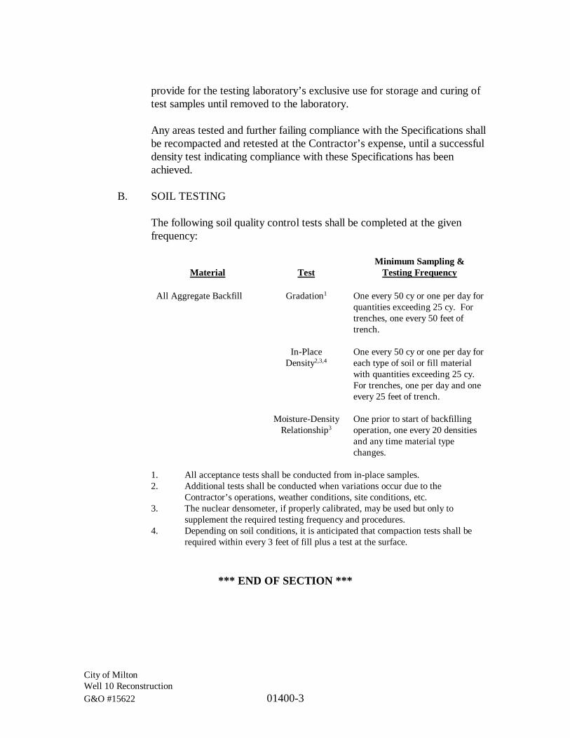
City of MiltonWell 10 ReconstructionG&O #15622 01400-3
provide for the testing laboratory’s exclusive use for storage and curing oftest samples until removed to the laboratory.
Any areas tested and further failing compliance with the Specifications shallbe recompacted and retested at the Contractor’s expense, until a successfuldensity test indicating compliance with these Specifications has beenachieved.
B. SOIL TESTING
The following soil quality control tests shall be completed at the givenfrequency:
Material TestMinimum Sampling &
Testing Frequency
All Aggregate Backfill Gradation1 One every 50 cy or one per day forquantities exceeding 25 cy. Fortrenches, one every 50 feet oftrench.
In-PlaceDensity2,3,4
One every 50 cy or one per day foreach type of soil or fill materialwith quantities exceeding 25 cy.For trenches, one per day and oneevery 25 feet of trench.
Moisture-DensityRelationship3
One prior to start of backfillingoperation, one every 20 densitiesand any time material typechanges.
1. All acceptance tests shall be conducted from in-place samples.2. Additional tests shall be conducted when variations occur due to the
Contractor’s operations, weather conditions, site conditions, etc.3. The nuclear densometer, if properly calibrated, may be used but only to
supplement the required testing frequency and procedures.4. Depending on soil conditions, it is anticipated that compaction tests shall be
required within every 3 feet of fill plus a test at the surface.
*** END OF SECTION ***

City of MiltonWell 10 ReconstructionG&O #15622 01500-1
SECTION 01500
TEMPORARY FACILITIES
PART 1 GENERAL
1.1 SCOPE
The work specified in this Section includes the temporary facilities required for thisproject, but not necessarily limited to:
A. Temporary utilities such as water, electricity, telephone, off-site staging,and off-site parking.
B. Sanitary facilities.
C. Temporary enclosures such as fences, tarpaulins, barricades, and canopies.
PART 2 PRODUCTS
2.1 UTILITIES
A. TEMPORARY ELECTRICITY
The Contractor shall provide temporary power for construction at theproject site. He shall make arrangements with the electrical utility (toobtain temporary power) and shall pay all costs and fees charged by theutility associated with connection of temporary power. The Contractorshall provide all special connections, receptacles, panelboards, etc., whichare required for temporary service, and are not provided by the utility.
The Contractor shall furnish and install all temporary wiring and associatedequipment required to keep all portions of the existing facilities inoperation at all times.
Area distribution boxes shall be furnished, installed, and so located that theindividual trades may use their own construction-type extension cords toobtain proper power and artificial lighting at all points where required. TheContractor shall provide a main disconnect on all temporary wiring panels,labeled “MAIN DISCONNECT,” to ensure the safety of personnel usingextension cords and hand tools. Panels shall also be properly grounded andequipped with GFCI breakers in accordance with WISHA requirements.

City of MiltonWell 10 ReconstructionG&O #15622 01500-2
The Contractor shall provide the Engineer single line diagrams of thetemporary wiring showing all circuit breakers. These diagrams shall beprovided prior to installation of this wiring. These diagrams are necessaryto provide information to Owner personnel for off-hours operation.
The Contractor shall pay all demand, consumption, taxes, and feesassociated with the temporary electrical service.
B. WATER
The Contractor shall be responsible for providing water necessary forconstruction. Water is available from the Owner free of charge, providedthat it is used responsibly. The Contractor shall install a meter withbackflow prevention device prior to obtaining water from the Owner.
2.2 SANITARY FACILITIES
The Contractor shall provide toilet and wash-up facilities for his workforce at thesite of work. They shall comply with applicable laws, ordinances, and regulationspertaining to the public health and sanitation of dwellings and camps.
2.3 OFF-SITE STAGING AND PARKING
The Contractor shall note that space is limited throughout the construction site.Employees of the Contractor, all subcontractors, vendors, suppliers, andassociated personnel shall not be allowed to park onsite during the course ofconstruction. It shall be the responsibility of the Contractor to provide sufficientparking facilities in authorized area(s) other than the construction site for theabove-mentioned personnel.
In addition, the Contractor shall not be allowed to stockpile and store equipmentand materials throughout the construction site. The Contractor shall coordinatehis schedule so that all equipment and materials shall be brought to theconstruction site only when they are to be installed/utilized.
2.4 ENCLOSURES
The Contractor shall furnish, install, and maintain during the project time allrequired scaffolds, tarpaulins, barricades, canopies, warning signs, steps, bridges,platforms, and other temporary construction necessary for proper completion ofthe work in compliance with all pertinent safety and other regulations.

City of MiltonWell 10 ReconstructionG&O #15622 01500-3
PART 3 EXECUTION
All temporary facilities and controls shall be maintained as long as required for thesafe and proper completion of the work. The Contractor shall remove suchtemporary facilities and controls as rapidly as progress of the work will permit oras directed by the Owner.
*** END OF SECTION ***

City of MiltonWell 10 ReconstructionG&O #15622 01505-1
SECTION 01505
MOBILIZATION AND DEMOBILIZATION
PART 1 GENERAL
1.1 SCOPE
The work specified in this Section consists of mobilization and demobilization.Mobilization consists of preconstruction activities and preparatory work for theproject necessary to mobilize labor, materials, and equipment to the project site.Demobilization consists of activities to remove materials and equipment from theproject site upon project completion, including final cleanup. Items which are notconsidered mobilization or demobilization include but are not limited to:
A. On-going activities throughout the duration of construction.
B. Profit, interest on borrowed money, overhead, or management costs.
1.2 RELATED WORK SPECIFIED ELSEWHERE
Section ItemDivision 1 General Technical Requirements
PART 2 PRODUCTS
Products and materials required for mobilization and demobilization are describedin the various sections of Division 1 and in other parts of the Contract Documents.
PART 3 EXECUTION
Complete mobilization and demobilization as required by the various sections ofDivision 1 and other parts of the Contract Documents.
*** END OF SECTION ***

City of MiltonWell 10 ReconstructionG&O #15622 01720-1
SECTION 01720
RECORD DRAWINGS
PART 1 GENERAL
1.1 SCOPE
The work specified in this Section includes the record drawings, which shall bemaintained and annotated by the Contractor during construction.
1.2 RELATED WORK SPECIFIED ELSEWHERE
Section Item01300 Submittals
1.3 INFORMATION PROVIDED BY THE OWNER
The Contractor will be provided with the following items to maintain recorddrawings for the project:
A. One full size paper set of Plans.
PART 2 PRODUCTS
Not Used
PART 3 EXECUTION
3.1 GENERAL
The Contractor shall maintain the following record drawings for the project:
A. A neat and legibly marked set of Contract Plans showing the final locationof piping, equipment, electrical conduits, outlet boxes and cables;
B. Additional documents such as schedules, lists, drawings, and electrical andinstrumentation diagrams included in the Contract Documents; and
C. Contractor layout and installation drawings.
Unless otherwise specified, record drawings shall be full size and maintained in aclean, dry, and legible condition. Record documents shall not be used forconstruction purposes and shall be available for review by the Engineer during

City of MiltonWell 10 ReconstructionG&O #15622 01720-2
normal working hours at the Contractor’s field office. At the completion of thework, prior to final payment, all record drawings shall be submitted to theEngineer.
Marking of the drawings shall be kept current and shall be done at the time thematerial and equipment are installed. Annotations to the record documents shallbe made with an erasable colored pencil conforming to the following color code:
A. Additions - Red
B. Deletions - Green
C. Comments - Blue
D. Dimensions - Graphite
Legibly mark drawings to record actual depths, horizontal and vertical location ofunderground raceways, cables, and appurtenances referenced to permanent surfaceimprovements.
The Contractor’s record drawings (full-size hard-copy) will be reviewed monthlyfor completeness by the Engineer prior to preparing the progress estimate forpayment. If the record drawings do not reflect the work performed, payment forthat item of work will not be included in the progress estimate.
*** END OF SECTION ***
City of MiltonWell 10 ReconstructionG&O #15622 01740-1
SECTION 01740
CLEANUP
PART 1 GENERAL
1.1 SCOPE
The work specified in this Section includes the maintenance of construction area(s)in a standard of cleanliness throughout the construction period as described herein.
Throughout the construction period, the Contractor shall maintain the cleanlinessof the site and structures as described herein. The Contractor is also to maintainaccess to all areas of the Public Works Site throughout construction.
Dust of all kinds, including concrete dust produced by construction activities, shallbe controlled to avoid damage to the existing facilities.
1.2 RELATED WORK SPECIFIED ELSEWHERE
In addition to standards described in this Section, comply with all requirements forcleaning up when described in other sections of these Contract Documents.
1.3 QUALITY ASSURANCE
The Contractor shall conduct daily site inspections, and more often if necessary, toverify that requirements are being met. The Owner and Engineer reserve the rightto perform the same inspections.
PART 2 PRODUCTS
2.1 CLEANING MATERIALS AND EQUIPMENT
Provide all required personnel, equipment, and materials needed to maintain thespecified standard of cleanliness.
2.2 COMPATIBILITY
Use only the cleaning materials and equipment which are compatible with thesurface being cleaned, as recommended by the manufacturer of the material or asapproved by the Engineer.

City of MiltonWell 10 ReconstructionG&O #15622 01740-2
PART 3 EXECUTION
3.1 PROGRESS CLEANING
A. GENERAL
Retain all stored materials and equipment in an orderly fashion allowingmaximum access, not impeding drainage or traffic, and providingprotection.
Do not allow the accumulation of scrap, debris, waste material, and otheritems not required for this work.
At least twice each month, and more often if necessary, completely removeall scrap, debris, and waste material from the project site.
Provide adequate storage for all materials awaiting removal from theproject site, observing all requirements for fire protection and protection ofthe environment.
B. SITE
Daily, and more often if necessary, inspect the site and pick up all scrap,debris, and waste material. Move these items into a place designated fortheir storage until disposal becomes available.
Weekly, and more often if necessary, inspect all arrangements of materialsstored on the site, restack, arrange, or otherwise service all arrangementsto meet the requirements above.
Maintain the site in a neat and orderly condition at all times so as to meetthe approval of the Engineer.
C. STREETS
All paved and unpaved streets in the vicinity of the project shall be keptfree of material tracked from the project site or dropped from vehiclesentering and leaving the site. The Contractor shall inspect roads in eachactive area daily, and all material deposited on the road from theContractor’s activities shall be removed prior to the end of the workday.This shall include sweeping, as required, to collect any mud, dirt and dustfrom the surface. All catch basins and culverts in the work area shall beinspected before completion and cleaned as directed by the Engineer.

City of MiltonWell 10 ReconstructionG&O #15622 01740-3
3.2 FINAL CLEANING
A. DEFINITION
Except as otherwise specifically provided, “clean” shall be interpreted asmeaning the level of cleanliness generally provided by commercial buildingmaintenance equipment and materials.
B. GENERAL
Prior to final inspection, remove from the jobsite all tools, surplusmaterials, equipment, scrap, debris, and waste. Conduct final projectcleaning as described below.
C. TIMING
Schedule final cleaning as approved by the Engineer to enable the Owner toaccept a completely clean project, ready for occupancy.
*** END OF SECTION ***

City of MiltonWell 10 ReconstructionG&O #15622 01900-1
SECTION 01900
SALVAGE AND DEMOLITION
PART 1 GENERAL
1.1 SCOPE
The work specified in this Section covers the demolition of existing structures,piping, equipment, and sitework, and the salvage of existing materials andequipment as indicated on the Plans and as specified herein.
The Plans show the major items to be demolished and salvaged. The Contractorshall, however, remove any other incidental above-grade and below-grade itemswhich are not to be used in the completed project.
1.2 RELATED WORK SPECIFIED ELSEWHERE
Section Item01110 Summary of Work01500 Temporary Facilities
1.3 SALVAGE
Salvageable equipment and material shall be removed and stored with care so asnot to impair future uses and shall include all equipment and material so indicatedon the Plans.
Salvaged equipment and material not reused or rejected by the Owner shall becleaned and protected from corrosion and weather and delivered by the Contractorto the Owner at the Public Works Building.
Reuse of salvageable equipment and material by the Contractor will not bepermitted except where specifically indicated on the Plans and Specifications orwhere approved by the Engineer and Owner. Salvageable equipment and materialsrejected in writing by the Owner shall become the property of the Contractor andbe disposed of away from the site without additional cost to the Owner.
1.4 CONTROL VALVE AND MAGMETER SALVAGE AND RE-USE
The services of a factory trained representative of the control valve and themagnetic flowmeter manufacturers, Cla-Val and Toshiba, respectively, shall beprovided. Services shall include at a minimum a half day onsite for inspection ofthe existing equipment and one additional half day for the supervision of equipment

City of MiltonWell 10 ReconstructionG&O #15622 01900-2
startup, testing and instruction of the Owner’s personnel in the operation andmaintenance of the equipment. The cost of these services shall be included in thebid price. Instruction and training shall not take place until valve startup iscompleted and the valves are fully operational.
1.5 DEMOLITION
The Contractor shall be responsible for compliance with current City, County,State, and Federal codes and regulations related to demolition.
The Contractor shall notify all affected utilities and comply with their respectiverequirements for abandonment of such utilities including power, telephone, naturalgas, water, sanitary sewer, and storm sewer utilities.
The Contractor shall maintain access for the Owner’s employees during thedemolition period and provide barricades, fences, etc., as required for job sitesafety.
All piping and appurtenances located less than 3 feet below finished grade shall beremoved and hauled to an approved disposal site. All piping and appurtenanceslocated three feet or more below finished grade may be abandoned in place, unlessshown otherwise on the Plans, as long as Contractor fully seals all pipe andappurtenance openings with grout to two diameters of the host pipe.
All waste materials from demolition or cutting shall become the property of theContractor and shall be removed from the site and hauled to an approved wastedisposal site, if declared surplus by the Owner. All materials and equipment,however, are property of the Owner unless declared surplus. Some equipment andmaterials scheduled for salvage and reuse or delivery to the Owner are noted onthe Plans.
1.6 WELL DECOMMISSIONING
As shown on the Plans, Well 10, Well 7, the Groundwater Monitoring Well andpotentially Well 6 shall be decommissioned by a licensed well driller in accordancewith WAC 173-160-381. Decommissioning of Well 6 is an Additive item of work.The well driller shall be responsible for the permits and notifications required bythe Washington State Department of Ecology including filing of the Notice ofIntent Form to Decommission a Well. The well logs for the existing wells areincluded in the Appendices. At the Contractor’s option, the wells may bedecommissioned using one of the following methods:
A. Perforate the casing from the bottom to within 5 feet of the surroundingfinished grade and pressure grout the casing. Casing and all appurtenances

City of MiltonWell 10 ReconstructionG&O #15622 01900-3
within 5 feet of the surrounding grade shall be removed
B. Withdraw the casing and fill the hole with cement grout as the casing isbeing withdrawn.
*** END OF SECTION ***
DIVISION 2
SITE WORK

City of MiltonWell 10 ReconstructionG&O #15622 02050-1
SECTION 02050
LOCATE EXISTING UTILITIES
PART 1 GENERAL
1.1 SCOPE
The work specified in this Section includes the anticipated conflicts, which mayexist with existing utilities. A reasonable attempt has been made to locate theexisting utilities; however, the exact location, and/or depth are unknown in mostinstances. Locations and dimensions shown in the Plans for existing facilities arein accordance with available information obtained without uncovering,measuring, or other verification. It shall be the responsibility of the Contractor tolocate existing utilities and their depth.
1.2 RELATED WORK SPECIFIED ELSEWHERE
Section Item02250 Temporary Shoring and Bracing02300 Earthwork
PART 2 PRODUCTS
Not Used.
PART 3 EXECUTION
3.1 GENERAL
The Contractor shall determine the difficulties to be encountered in constructingthe Project and his locate effort based upon the information provided on the Plans,field investigation, and the Contractor’s contacts with the existing utilitycompanies. The Contractor shall determine the extent of exploration required tofirst prevent damage to those existing utilities, and secondly to determine if theproposed improvements are in conflict with existing utilities.
The Contractor shall locate existing utilities sufficiently ahead of construction sothat the Engineer can modify the alignment, or grade prior to construction. Wherethe alignment of the proposed utility cannot be adjusted to miss the existing utilitywithout installation of additional pipe or fittings, the Contractor may be entitled toadditional compensation to reroute the proposed utility.
The Contractor shall call the Utility Location Request Center (One Call Center),for field location, not less than 2 nor more than 10 business days before the

City of MiltonWell 10 ReconstructionG&O #15622 02050-2
scheduled date for commencement of excavation that may affect undergroundutility facilities, unless otherwise agreed upon by the parties involved. A businessday is defined as any day other than Saturday, Sunday, or a legal local, State, orFederal holiday. The telephone number for the One Call Center for this project is(800) 424-5555. If no one-number locator service is available, notice shall beprovided individually to those owners known to or suspected of havingunderground facilities within the area of the proposed excavation.
The Contractor is alerted to the existence of Chapter 19.122 RCW, a law relatingto underground utilities. Any cost to the Contractor incurred as a result of thislaw shall be at the Contractor’s expense.
No excavation shall begin until all know facilities in the vicinity of the excavationarea have been located and marked.
*** END OF SECTION ***

City of MiltonWell 10 ReconstructionG&O #15622 02240-1
SECTION 02240
DEWATERING
PART 1 GENERAL
1.1 SCOPE
The work specified in this Section includes dewatering excavations of any kind andlocation, including but not limited to groundwater, surface water, andprecipitation, until backfilling has been completed to finished grade.
1.2 RELATED WORK SPECIFIED ELSEWHERE
Section Item01300 Submittals02300 Earthwork02370 Erosion Control
1.3 SUBMITTALS
Prior to the start of construction, the Contractor shall submit a dewatering plan inaccordance with Section 01300 containing both a graphical and narrativepresentation identifying proposed methods, equipment sizes and contingency plansshould dewatering cause settlement of any adjacent facilities. The dewatering planshall show specific locations, in plan and section, where dewatering is expected aswell as a general discussion of methods to be employed should water beencountered in other locations.
Acceptance by the Owner of the method, installation, and operation andmaintenance details submitted by the Contractor shall not in any way be consideredto relieve the Contractor from full responsibility for errors therein or from theentire responsibility for complete and adequate design and performance of thesystem in controlling the water level in the excavated areas, and for control of thehydrostatic pressures to the depths specified herein. The Contractor shall be solelyresponsible for the proper design, installation, proper operation, maintenance, andany failure of any component of the dewatering system.
1.4 REFERENCES
“Rossum J.R., 1954, Control of Sand in Water Systems, Journal American WaterWorks Association, Volume 46, pp. 123-132”
Geotechnical Report, PanGEO, Inc. (in appendix)

City of MiltonWell 10 ReconstructionG&O #15622 02240-2
1.5 QUALITY CONTROL
It shall be the sole responsibility of the Contractor to control the rate and effect ofthe dewatering efforts to avoid all objectionable settlement and subsidence. TheContractor shall comply with local codes and ordinances of governing authoritieswith regard to disposal of water pumped from dewatering operations.
Proposed discharge points shall be approved by the Owner prior to implementationof dewatering. The Contractor shall be responsible for taking all reasonableprecautions necessary to ensure continuous, successful operation of the system.
PART 2 PRODUCTS
The Contractor shall have sufficient pumping equipment and/or other machineryavailable onsite before operations begin to assure that the operation of thedewatering system can be maintained. This shall include providing backup pumpsof similar capacity and a standby generator of the capacity required to continuouslyoperate the Contractor’s dewatering system.
PART 3 EXECUTION
3.1 INSTALLATION AND APPLICATION
During construction, the installation of piping, conduits and structures and duringthe placing of backfill, excavations shall be kept free of water, subsurface orotherwise. The Contractor shall furnish all equipment necessary to dewater theexcavations and shall dispose of the water so as not to cause a nuisance or menaceto the public. The dewatering system shall be installed and operated by theContractor so that the groundwater level outside the excavation is not reduced tothe extent that would damage or endanger adjacent structures or property. Therelease of groundwater to its static levels shall be performed so as to maintain theundisturbed state of the foundation soils, prevent disturbance of backfill andprevent movement of all structures and pipelines.
Design implementation and maintenance of any dewatering system shall be theresponsibility of the Contractor.
The Contractor shall construct any dewatering wells in accordance withWAC 173-160. The dewatering system shall be sufficient to maintain thegroundwater level at an elevation to protect the surface of the trench bottoms, thebase of the bedding course or other foundation, and shall be accomplished prior topipe laying and jointing or placement of reinforcing steel for concrete.

City of MiltonWell 10 ReconstructionG&O #15622 02240-3
3.2 FIELD QUALITY CONTROL
A continual check by the Contractor shall be maintained to ensure that thesubsurface soil is not being removed by the dewatering operation. The Contractorshall test all dewatering discharge using a Rossum Sand Tester or equivalent todetermine the silica content of the discharge. The Contractor shall notify theOwner at least 24 hours prior to testing. Where critical structures or facilities existimmediately adjacent to areas of proposed dewatering, reference points shall beestablished and observed at frequent intervals to detect any settlement that coulddevelop.
Should settlement be observed, the Contractor shall cease dewatering operationsand implement contingency plans as outlined in the Contractor’s approveddewatering plan. The responsibility for conducting the dewatering operation in amanner that protects adjacent structures and facilities rests solely on theContractor. The cost of repairing any damage to adjacent structures andrestoration of facilities shall be the responsibility of the Contractor. Permanentpiping systems, existing or new, shall not be incorporated into the Contractor’sdewatering system.
*** END OF SECTION ***

City of MiltonWell 10 ReconstructionG&O #15622 02250-1
SECTION 02250
TEMPORARY SHORING AND BRACING
PART 1 GENERAL
1.1 SCOPE
The work specified in this Section includes the temporary shoring and bracing forexcavations including the trench excavation safety systems as shown on the Plansand as specified herein.
1.2 RELATED WORK SPECIFIED ELSEWHERE
Section Item01300 Submittals02300 Earthwork
1.3 GEOTECHNICAL REPORT
Geotechnical Report, PanGEO, Inc. (in appendix)
1.4 WORK INCLUDED
The extent of temporary shoring and bracing work includes, but is not limited to:
A. Temporary shoring and bracing necessary to protect the following againstloss of ground or caving embankments: existing structures, buildings,roads, walkways, utilities, electrical transmission towers and supportwiring, other facilities and improvements where required to comply withcodes and authorities having jurisdiction.
B. Trench excavation safety systems, pursuant to RCW Chapter 49.17 andWAC 296-155-655.
C. Maintenance of shoring and bracing.
1.5 QUALITY ASSURANCE
A. SHORING CONSULTANT
The Contractor shall engage the services of a qualified geotechnicalengineer and qualified structural engineer registered in the State ofWashington to design temporary shoring and bracing when required byapplicable regulations.

City of MiltonWell 10 ReconstructionG&O #15622 02250-2
B. SHORING DESIGN
The Contractor shall provide layout and design drawings andspecifications for shoring and bracing when a trench box is inadequate forthe purpose or will not be used and trench depth exceeds 4 feet and backsloping will not be used. Temporary shoring and bracing system designand calculations shall be prepared, stamped, and signed by a ProfessionalEngineer registered in the State of Washington.
C. REGULATIONS
The Contractor shall design sheeting, shoring and bracing in accordancewith the Washington State Safety Code and any local codes andordinances of governing authorities having jurisdiction
1.6 SUBMITTALS
The Contractor shall submit shoring and bracing layout and design drawings,calculations and other backup data to the Owner for review in accordance withSection 01300 prior to the start of construction.
1.7 PROJECT CONDITIONS
A. SOILS INFORMATION
A Geotechnical investigation has been conducted for this project and acopy of the report is included in the Appendix.
B. SITE SURVEY
The background survey information provided on the Plans is shown forclarity only. The Contractor shall determine, before commencing work,the exact location of all existing features that may be disrupted by newconstruction, including existing underground utilities. The Contractorshall be fully responsible for any and all damages, which might be causedby the Contractor’s failure to exactly locate and/or preserve existing sitefeatures. Prior to commencing work, the Contractor shall check and verifygoverning dimensions and elevations.
The Contractor shall survey adjacent structures and facilities, establishingexact elevations at fixed points to act as temporary bench marks tomonitor potential settlement from the contractor’s ongoing operations.Clearly identify temporary bench marks and record existing elevationsfrom the control points shown on the Plans.

City of MiltonWell 10 ReconstructionG&O #15622 02250-3
During excavation, the Contractor shall resurvey bench marks weekly.The Contractor shall maintain and make available at the job site anaccurate log of surveyed elevations for comparison with originalelevations, and promptly notify the Owner if changes in elevations occuror if cracks, sags or other damage is evident.
1.8 EXISTING UTILITIES
The Contractor shall protect existing active sewer, water, gas, electrical, and otherutility services and structures that may be present. This shall also include allpipelines, services, and structures that are the property of the Owner.
PART 2 PRODUCTS
The Contractor shall provide suitable shoring and bracing materials, which shallsupport loads imposed. Materials for shoring systems need not be new, but shallbe in serviceable conditions.
PART 3 EXCAVATION
3.1 VERIFICATION OF CONDITIONS
The Contractor shall notify the Owner immediately if, during construction,subsurface conditions are different from those encountered in the exploratoryholes or as described in the Geotechnical Report.
3.2 INSTALLATION AND APPLICATION
The Contractor shall provide shoring systems adequately anchored and braced toresist earth and hydrostatic pressures at locations as needed to support excavationsduring construction. The Contractor shall locate required bracing to clear allpermanent work. Bracing which must be relocated shall be installed prior to theremoval of original bracing. The Contractor shall not place bracing where it willbe cast into or included in permanent concrete work, except as otherwiseacceptable to the Owner. The Contractor shall maintain bracing until structuralelements are rebraced by other bracing or until permanent construction is able towithstand lateral earth and hydrostatic pressures.
3.3 REMOVAL
The Contractor shall remove shoring and bracing in stages to avoid disturbancesto adjacent and underlying soils and damage to structures, pavements, facilitiesand utilities. The Contractor shall repair or replace, as acceptable to the Owner,

City of MiltonWell 10 ReconstructionG&O #15622 02250-4
adjacent work damaged or displaced through the installation or removal ofshoring and bracing work.
3.4 EXCAVATION SAFETY SYSTEMS
All work shall be carried out with due regard for public safety. Open trenchesshall have proper barricades and at night they shall be distinctly indicated byadequately placed lights, as provided for elsewhere in the Specifications.
The Contractor is reminded that the Owner has not so delegated, and the Owner’sRepresentative does not purport to be a trench or excavation system safety expert,is not so engaged in that capacity under this Contract, and has neither theauthority nor the responsibility to enforce construction, safety laws, rules,regulations, or procedures or to order the stoppage of work for claimed violationsof trench or excavation safety.
The furnishing by the Owner of resident representation and inspection personnelshall not make the Owner responsible for the enforcement of such laws, rules,regulations, or procedures, nor shall such make the Owner responsible forconstruction means, methods, techniques, sequences, procedures, or for theContractor’s failure to properly perform the work necessary for proper trench andexcavation safety.
*** END OF SECTION ***

City of MiltonWell 10 ReconstructionG&O #15622 02300-1
SECTION 02300
EARTHWORK
PART 1 GENERAL
1.1 SCOPE
The work specified in this Section includes the earthwork, including trenchexcavation and backfill for piping, excavation and backfill for structures, andfinish grading.
1.2 RELATED WORK SPECIFIED ELSEWHERE
Section Item01300 Submittals01500 Temporary Facilities02240 Dewatering02250 Temporary Shoring and Bracing02305 Wet Weather Earthwork02370 Erosion Control02700 Gravel Materials
PART 2 PRODUCTS
2.1 GRAVEL MATERIALS
All gravel materials shall conform to Section 02700.
PART 3 EXECUTION
3.1 PREPARATION
Excavation may commence once all erosion control measures are in place inaccordance with the Plans and Section 02370 and to the satisfaction of the Owner.
3.2 GENERAL REQUIREMENTS
Excavation, compaction and backfill for structures, pipelines and the final sitecontours shall be formed by either excavating or compacting fill, as required, toprovide the cross-sections as shown on the Plans.
All excavation performed on this Project shall be considered unclassified.Excavation shall consist of the removal of any and all material encountered,including debris, rubble, concrete, metal, topsoil, cutting and removal of existing

City of MiltonWell 10 ReconstructionG&O #15622 02300-2
surfacing, tree stumps, trees, logs, abandoned rail ties, abandoned piping, piling,riprap, etc.
Excavations shall be kept free of water, both surface water and groundwater,during the excavation, installation of pipelines and structures, and the placementof backfill. For additional requirements see Section 02240.
The Contractor’s attention is also called to the depth of the structures and piping;for this reason, special shoring and bracing may be required. All shoring andbracing or sheeting required to perform and protect the excavation and tosafeguard the employees, shall be furnished by the Contractor. For additionalrequirements see Section 02250.
No timber bracing, lagging, sheathing or other lumber shall be left in anyexcavation except with permission of the Engineer and in the event suchpermission is granted, no separate payment shall be allowed for burying suchmaterial.
All stockpiles shall be covered with plastic and no stockpile shall be higher than6 feet above existing grade.
3.3 EXCAVATION AND BACKFILL FOR STRUCTURES
Excavation and backfill for structures shall be in conformance with Section 2-09of the WSDOT Standard Specifications, and as further described herein. Allexcavation for structures shall be done to the dimensions and levels indicated onthe Plans or specified herein. Excavation shall be made to such width outside thelines of the structures to be constructed as may be required for proper workingmethods, the erection of forms and the protection of the work.
Excavation shall consist of the removal of any and all material encountered to theelevations shown on the Plans. Excavations for structures shall be continueddown to the subgrade which is defined as 12 inches below concrete matfoundations, concrete footings, and slab on grade floors for the installation offoundation gravel material, unless otherwise noted on the Plans.
Fill material placed under structures, including footings and floor slabs, shall befoundation gravel as specified in Section 02700.
In the event unsuitable material is encountered below the subgrade shown on thePlans and described herein, the Contractor, as required by the Engineer, shallover-excavate until a suitable foundation is reached.

City of MiltonWell 10 ReconstructionG&O #15622 02300-3
The Contractor shall notify the Engineer when excavation for compacted fill orstructures is complete. No forms, reinforcing steel, or concrete shall be placeduntil the excavation has been inspected by the Engineer.
Backfill for structures shall be Bank Run Gravel as specified in Section 02700.
3.4 PROTECTION OF FOUNDATION SURFACES
Care shall be taken to preserve the foundation surfaces shown on the Plans in anundisturbed condition. If the Contractor unnecessarily over excavates or disturbsthe foundation surfaces shown on the Plans or specified herein without writtenauthorization of the Engineer the Contractor shall replace such foundations withconcrete fill or other suitable material approved by the Owner in a manner whichwill show by test an equal bearing capacity with the undisturbed foundationmaterial. No additional payment shall be made for the added quantity of concretefill or other suitable material used because of unnecessary over excavation causedby the Contractor or his operations.
3.5 EXCAVATION AND BACKFILL FOR TRENCHES
Excavation and backfill for trenches shall be in conformance with Sections 7-08and 7-09 of the WSDOT Standard Specifications, and as further described herein.
Upon completion of work each day, all pipeline open trenches shall be completelybackfilled, leveled, and temporarily patched or graveled, as herein specified.Under certain conditions, the trench may be left open at the last length of pipe laidduring the day to avoid re-excavation the following morning, provided that theopening is adequately plated or covered for vehicle traffic. Special attention shallbe given to barricading to keep vehicular traffic away from newly-backfilledtrench areas until restored for traffic.
The Engineer reserves the right to restrict the Contractor in the amount of trenchfor pipeline that can be opened during the working day. Should the Contractor, inthe Engineer’s opinion, fail to diligently pursue backfilling, an allowable limit ofopen trench shall be 100 lineal feet and shall be strictly enforced.
The width of the trench at or below a point 12 inches above the top of the outsidediameter of the pipe shall be carefully controlled and maintained to ensure thestrength of the pipe and prevent pipe failures. Backfilling shall proceed asfollows:
A. SUBGRADE PREPARATION
The subgrade for piping is defined as the elevation of the bottom of thepipe bedding material as shown on the Plans.

City of MiltonWell 10 ReconstructionG&O #15622 02300-4
In the event unsuitable material is encountered below the subgrade shownon the Plans and described herein, the Contractor, as required by theEngineer, shall over-excavate until a suitable foundation is reached.
B. BEDDING FOR PIPE
Above the foundation material, if any, Gravel Backfill for Pipe ZoneBedding, as specified in Section 02700, shall be placed in lifts ofapproximately 8 inches up to a point 12 inches above the pipe. Thismaterial shall be hand shoveled in place and carefully worked under andaround the pipe.
Partial backfill to protect the pipe will be permitted immediately after thepipe has been properly laid in accordance with the Plans and theseSpecifications. Complete backfilling of the pipe zone will not bepermitted until the section of pipe installed has been inspected by theEngineer.
C. BACKFILL FOR TRENCHES
Above the pipe bedding, the backfill material to be used in the trenchsection shall be Bank Run Gravel, as specified in Section 02700. TheContractor shall place backfill in horizontal lifts not to exceed 8 inches inthickness.
The Contractor shall remedy, at his expense, any defects that appear in thebackfill prior to final acceptance of the work. Cleanup operations shallprogress immediately behind backfilling to accommodate the return tonormal use of the trench area.
During placement of the initial lifts, the backfill material shall not bebulldozed into the trench or dropped directly over the pipe with less than3 feet of backfill material above the top of the pipe.
3.6 ROCK EXCAVATION
It is not anticipated that solid rock will be encountered. Should such material beencountered, however, it will be paid for by change order as directed by theEngineer and as approved by the Owner. Boulders or broken rock less than 2cubic yards in volume as measured in the field by the Engineer will not beclassified as rock, nor will so-called “hard-pan” or cemented gravel even though itmay be advantageous to use explosives in its removal if blasting were allowed.For the purpose of this Contract, rock excavation shall be defined as mineralmatter in place and of such hardness and texture that, when it is encountered,
City of MiltonWell 10 ReconstructionG&O #15622 02300-5
cannot be loosened by three passes of a ripper tooth mounted on the larger of atracked backhoe of at least 25,000 pounds operating weight and 75 horsepower orthe largest backhoe being utilized on the job by the Contractor. Where rocksoccur as boulders that are smaller than the larger of: (1) 2 cubic yards in volume,or (2) the volume that can be readily handled by the largest backhoe being utilizedon the job by the Contractor, they shall be considered incidental to excavation.
Where removal of a boulder results in a void below the desired elevation of theintended excavation, backfilling of the void shall be handled in the same manneras the replacement of unsuitable excavated material.
3.7 DISPOSAL OF EXCAVATED MATERIAL
Excavated material shall be hauled to an approved waste site(s), as selected by theContractor. The Contractor shall submit a list of approved waste haul site(s) tothe Owner prior to the commencement of hauling of waste materials. Anypermits required for waste haul and disposal shall be the responsibility of theContractor.
3.8 FINAL SITE GRADING
The site shall be graded consistent with the elevations shown on the Plans. Theslopes between elevations shall be uniform or as shown on the Plans. Excavationsand backfill shall be to the elevations required for the placement of all surfacerestorations, such as asphalt, concrete, gravel surfacing, or landscaping. All areasshall be graded to provide proper drainage. The final ground surface, outside oftraveled areas, shall be smooth, raked free of debris and stones, and prepared forrestoration as specified in Section 02950.
3.9 STRUCTURE COMPACTION
Structure backfill material placed underneath and around structures shall bemoisture conditioned to within 3 percent of optimum moisture content and shallbe placed in loose, horizontal layers. The thickness of layers placed beforecompaction shall not exceed 8 inches for heavy equipment compactors and shallnot exceed 4 inches for hand-operated mechanical compactors. Water settlementis not allowed for compaction.
Layers shall be compacted to a dense state equaling at least 95 percent of themaximum dry density, using the Modified Proctor, per ASTM D1557. Any andall compaction within 5 feet of all walls shall be accomplished by means of hand-operated mechanical equipment rather than heavy equipment compactors.

City of MiltonWell 10 ReconstructionG&O #15622 02300-6
3.10 TRENCH COMPACTION
Trench backfill material shall be moisture conditioned to within 3 percent ofoptimum moisture content and shall be placed in loose, horizontal layers. Thethickness of layers placed before compaction shall not exceed 8 inches for heavyequipment compactors and shall not exceed 4 inches for hand-operatedmechanical compactors. Water settlement is not allowed for compaction.
Layers shall be compacted to a dense state equaling at least 95 percent of themaximum dry density, using the Modified Proctor, per ASTM D1557. Any andall compaction within 5 feet of all walls shall be accomplished by means of hand-operated mechanical equipment rather than heavy equipment compactors.
*** END OF SECTION ***

City of MiltonWell 10 ReconstructionG&O #15622 02305-1
SECTION 02305
WET WEATHER EARTHWORK
PART 1 GENERAL
1.1 SCOPE
The work specified in this Section includes the procedures to be followed ifearthwork is to be accomplished in wet weather or in wet conditions where controlof soil moisture is difficult.
1.2 RELATED WORK SPECIFIED ELSEWHERE
Section Item01300 Submittals0230002370
EarthworkErosion Control
02700 Gravel Materials
PART 2 PRODUCTS
The size or type of construction equipment shall be selected as required to preventsoil disturbance. In some instances, it may be necessary to limit equipment size orto excavate soils with a backhoe, Gradall, or equivalent type of equipment tominimize subgrade disturbance caused by construction traffic.
If placement of aggregates must occur during wet weather, as determined by theContractor, then it shall be the Contractor’s responsibility to ensure the materialplaced will meet the earthwork requirements herein. Upon approval by theEngineer and at no additional cost to the Owner, the Contractor may proposealternate aggregates to allow work to continue.
Import aggregate materials used during wet weather earthwork shall generallyconsist of clean granular material containing less than 5 percent fines (materialpassing the U.S. Standard No. 200 sieve), based on wet sieving the fractionpassing the 3/4-inch sieve. The fines shall be non-plastic.

City of MiltonWell 10 ReconstructionG&O #15622 02305-2
PART 3 EXECUTION
3.1 WET WEATHER EXCAVATION AND FILL PLACEMENT QUALITYCONTROL
Excavation and placement of fill or backfill material will be observed on a full-timebasis by the Owner, to determine that all work is being accomplished in accordancewith these Specifications.
3.2 WET WEATHER EARTHWORK PROTECTION
The ground surface shall be sloped away from construction areas to promote therapid runoff of precipitation and prevent ponding of water.
Earthwork shall be accomplished in small sections to minimize exposure to wetweather. Excavation or the removal of unsuitable soil shall be followedimmediately by the placement and compaction of a suitable thickness (generally8 inches or more if approved by the Owner) of clean foundation gravel.
No soil shall be left uncompacted and exposed to moisture. A smooth drumvibratory roller, or equivalent, shall be used to seal the ground surface afterplacement of fill or backfill materials.
All wet weather work shall meet local, state and federal codes as specified hereinand as indicated on the Plans.
*** END OF SECTION ***

City of MiltonWell 10 ReconstructionG&O #15622 02370-1
SECTION 02370
EROSION CONTROL
PART 1 GENERAL
1.1 SCOPE
The work specified in this Section includes the spill control and countermeasures,and the temporary erosion and sedimentation control (TESC) in and around thesite caused by the actions of the Contractor as shown on the Plans and as specifiedherein.
Work under this Section shall be directed towards site areas disturbed duringconstruction as well as all off-site storage and parking areas maintained by theContractor.
1.2 RELATED WORK SPECIFIED ELSEWHERE
Section Item01300 Submittals02240 Dewatering02300 Earthwork
1.3 CERTIFIED EROSION AND SEDIMENT CONTROL LEAD (CESCL)
The Contractor shall designate a Certified Erosion and Sediment Control Lead(CESCL) for this project. The CESCL shall have, for the life of this Contract, acurrent Certificate of Training in Construction Site Erosion and Spill Controlsigned by the WSDOT Water Quality Program Manager.
Duties of the CESCL shall include, but are not limited to:
A. Inspecting temporary erosion and spill control Best Management Practice(BMPs) for proper location, installation, maintenance, and repair.Inspections shall be made as noted on the Plans and after each significantprecipitation event, including those that occur during weekends and afterworking hours. A Temporary Erosion and Spill Control Inspection Reportshall be prepared for each inspection and shall be included in theTemporary Erosion and Spill Control file. The inspection report shallinclude, but not be limited to:
1. When BMPs are installed, removed or changed;
2. Repairs needed or made;

City of MiltonWell 10 ReconstructionG&O #15622 02370-2
3. Turbidity monitoring results;
4. Observations of BMP effectiveness and proper placement;
5. Recommendations for improving performance of BMPs.
B. Prepare and maintain a Temporary Erosion and Spill Control file on sitethat includes but is not limited to:
1. Temporary Erosion and Spill Control Inspection Reports;
2. Contractor’s Stormwater Pollution Prevention Plan (SWPPP);
3. Contractor’s Spill Prevention, Control, and Countermeasures Plan(SPCC);
4. Any project permits;
5. Manufacturer instructions for all products used for erosion and spillcontrol;
6. Washington State Department of Ecology’s StormwaterManagement Manual for Western Washington, Chapter 4, VolumeII, current edition.
1.4 SPILL PREVENTIONS, CONTROL, AND COUNTERMEASURES PLAN
The Contractor shall prepare and submit the spill prevention, control, andcountermeasures plan in accordance with Section 1-07.15(1) of the WashingtonState Department of Transportation Standard Specifications for Road, Bridge, andMunicipal Construction, current edition.
1.5 STORMWATER POLLUTION PREVENTION PLAN
The CESCL Contractor shall be responsible for preparing a Stormwater PollutionPrevention Plan (SWPPP). The intent of the SWPPP is to reflect the Contractor’soperations by supplementing the TESC Drawings, details, and notes shown on thePlans to provide comprehensive pollution control at the construction site, stagingareas, stockpiles, and borrow sites. The SWPPP shall be prepared by the CESCLfor the project and submitted in accordance with Section 01300. The SWPPP shallbe submitted to the Owner for approval at the preconstruction conference. Nowork shall begin until the Contractor’s SWPPP, as approved by the Owner, isimplemented. The SWPPP shall address, at least, the following items:

City of MiltonWell 10 ReconstructionG&O #15622 02370-3
· Identification of construction haul routes and location of BMPs (e.g.,stabilized construction entrance, silt fences, storm drain inlet protection).
· Waste disposal methods and locations.
· Detailed construction sequence and schedule, including identifying datesscheduled for BMP installation, removal, clearing, grading, seeding, andlandscaping.
· Details for any temporary flow diversions, dewatering systems, and BMPs(in accordance with the current edition of the Washington StateDepartment of Ecology’s Stormwater Management Manual for WesternWashington) proposed by the Contractor.
· Calculations for temporary sedimentation ponds, if used
· A list of products to be used, including Material Safety Data Sheets.
· Identification of stockpile and staging areas, and BMPs to be implementedat these locations.
· Details for any temporary dust control and BMPs proposed by theContractor.
The SWPPP shall be prepared in accordance with details shown on the Plans, theseSpecifications, and Chapter 4, from the current edition of the Washington StateDepartment of Ecology’s Stormwater Management Manual for WesternWashington, which are hereby referenced and made a part of the ContractDocuments. Only those sections of the Stormwater Management Manual forWestern Washington that address preparation, implementation, and maintenance ofpermanent and temporary erosion and sedimentation control BMPs are applicable.
PART 2 PRODUCTS
2.1 SILT FENCES
Silt fences shall conform to the details shown on the Plans and the fabric shallconform meet the requirements of Geotextile for Temporary Silt Fence ofSection 9-33 of the WSDOT Standard Specifications.
2.2 STORM DRAIN INLET (CATCH BASIN) PROTECTION
Storm drain inlet protection shall be with a “Ultra DrainGuard” as manufacturedby ACF Environmental, or equal.

City of MiltonWell 10 ReconstructionG&O #15622 02370-4
PART 3 EXECUTION
3.1 PREPARATION
Site preparation work shall be performed only during periods when beneficialresults can be obtained. When drought, excessive moisture or other unsatisfactoryconditions prevail, the work shall be stopped.
3.2 BEST MANAGEMENT PRACTICES (BMPS)
Silt fences shall be constructed to control erosion and migration of soils disturbedduring construction. The fences shall provide temporary protection and shall beremoved only upon approval of the Owner.
All areas or drainage ways downstream of the construction site shall have BestManagement Practices (BMPs) installed prior to the beginning of any clearingactivities. Runoff from cleared or disturbed area shall be directed through theBMPs. Disturbed ground shall be stabilized at the end of each work day.Permanent soil stabilization and erosion and sedimentation control shall beimplemented upon reaching finish grade. Slope protection shall be immediatelyimplemented upon any soils showing signs of erosion. This shall be done in amanner approved by the Owner.
All BMPs shall be inspected, maintained and kept in a condition sufficient toprovide effective erosion and sedimentation control at all times. The site shall beinspected to ensure the BMPs are properly located, constructed and operating asdesigned during the first storm. Any necessary adjustments or repairs shall bemade immediately and be approved by the Owner. The BMPs shall be inspectedthereafter as noted on the Plans and after all significant storm events. Turbiditymonitoring will be held on a weekly basis at a minimum, or more frequently ifnecessary as determined by the CESCL.
All BMPs shall be removed no later than 30 consecutive calendar days after finalsite stabilization has been achieved as determined by the Owner. BMPs such asstorm drain inlet protection, straw bales, silt fences and supports and plasticcoverings shall be removed and properly disposed of offsite by the Contractor.Areas disturbed by removal of these BMPs shall be immediately stabilized in amanner approved by the Owner.
*** END OF SECTION ***
City of MiltonWell 10 ReconstructionG&O #15622 02510-1
SECTION 02510
DISINFECTION
PART 1 GENERAL
1.1 SCOPE
The work specified in this Section includes disinfection of potable water piping,testing, and reporting results.
1.2 RELATED WORK SPECIFIED ELSEWHERE
Section ItemDivision 15 Mechanical
1.3 SUBMITTALS
A. TEST REPORTS
Indicate results comparative to specified requirements.
1.4 PROJECT RECORD DOCUMENTS
A. DISINFECTION REPORT
1. Type and form of disinfectant used.
2. Date and time of disinfectant injection start and time of completion.
3. Test locations.
4. Initial and 24-hour disinfectant residuals (quantity in treated water)in ppm for each outlet tested.
5. Date and time of flushing start and completion.
6. Disinfectant residual after flushing in ppm for each outlet tested.
B. BACTERIOLOGICAL REPORT
1. Date issued, project name, and testing laboratory name, address,and telephone number.

City of MiltonWell 10 ReconstructionG&O #15622 02510-2
2. Time and date of water sample collection.
3. Name of person collecting samples.
4. Test locations.
5. Initial and 24-hour disinfectant residuals in ppm for each outlettested.
6. Coliform bacteria test results for each outlet tested.
7. Certification that water conforms, or fails to conform, to bacterialstandards of the Department of Health.
8. Bacteriologist’s signature and authority.
1.5 QUALITY ASSURANCE
Perform Work in accordance with AWWA C651.
1.6 REGULATORY REQUIREMENTS
A. Conform to Department of Health code or regulation for performing thework of this Section.
B. Provide certificate of compliance from Department of Health indicatingapproval of water system.
PART 2 PRODUCTS
2.1 DISINFECTION CHEMICALS
Chemicals: AWWA B300, Hypochlorite, AWWA B301, Liquid Chlorine, AWWAB302, Ammonium Sulfate, and AWWA B303, Sodium Chlorite.
PART 3 EXECUTION
3.1 EXAMINATION
A. Verify that piping system has been cleaned, inspected, and pressure tested.
B. Perform scheduling and disinfection activity prior to startup, testing,adjusting and balancing, demonstration procedures, including coordinationwith related systems.

City of MiltonWell 10 ReconstructionG&O #15622 02510-3
3.2 WATER PIPE DISINFECTION
A. Provide and attach required equipment to perform the work of this Section.
B. Inject treatment disinfectant into piping system.
C. Maintain disinfectant in system for 24 hours.
D. Replace permanent system devices removed for disinfection.
E. Water for disinfection must be obtained by the Contractor by arrangementwith the Owner. The following describe specific procedures to be used bythe Contractor in maintaining a satisfactory environment for prevention ofcontamination of the proposed water system installation, the cleanliness ofthe pipe and fittings and the actual method of disinfection.
F. When the line is completed and ready to disinfect, water shall be allowed toflow in slowly, until it appears at the far end of the line so as not to displacethe disinfecting agent. The system shall then be allowed to stand for atleast 24 hours. The line shall then be flushed until a test shows no morethan two parts per million of available chlorine.
G. In all instances, the Contractor shall utilize a state approved double checkvalve type backflow prevention device to protect the potable water supplywhile filling, flushing and disinfecting the particular water main.
H. Where connections are made to existing facilities and it is impractical touse the methods described herein to disinfect the section between theexisting water main and the point of isolation of the new water main (valveor temporarily plugged line) or where pipes and fittings require immediateuse, cleaning and disinfecting shall be directed by the Owner.
I. The Contractor is herein advised that prior to making any restorations orpermanent connections to the existing water mains, that the Contractorshall first demonstrate to the Owner, that the new water main hasadequately passed a pressure test, been adequately flushed, and finallypassed the required bacteriological test.
J. In all disinfection processes, the Contractor shall take particular care influshing and wasting the chlorinated water from the mains to assure thatthe flushed and chlorinated water does no physical or environmentaldamage to property, streams, storm sewers or any waterways. TheContractor shall chemically or otherwise treat the chlorinated water to

City of MiltonWell 10 ReconstructionG&O #15622 02510-4
prevent damage to the effected environment, particularly aquatic and fishlife of receiving streams. The method and the time of flushing is to beapproved by the Owner.
K. Before placing the lines in service, satisfactory results must be obtained onsamples collected from representative points in the new system andsubmitted to a State DOH approved laboratory. The Owner shall collectall samples for the bacteriological tests. However, the Contractor shallnotify the Owner for collection of samples two days in advance, andschedule on days wherein samples can be conveniently processed by StateDOH approved laboratory. If any of the pipeline materials are replacedthereafter, then that section shall again be disinfected and tested forbacteriological count.
If disinfection of mains by the above methods, prove unsatisfactory and thelab report indicates any type of bacteria count, then the Owner may directthe Contractor to use one of the following two disinfection methods until asatisfactory report is obtained. No additional compensation will be madeto the Contractor for any work necessary to achieve a satisfactorybacteriological test result.
L. METHOD 1
A chlorine gas-water mixture, or dry chlorine gas may be applied by meansof a chlorinator, or the gas may be fed indirectly from a chlorine cylinderequipped with the proper devices for regulating the flow, and the effectivediffusion of gas within the pipe. (Use of the chlorinator is preferred todirect feed from the cylinder.)
1. Point of Application
The preferable point of application for the chlorinating agent is atthe beginning of the pipeline extension, or any valved sectionthereof, and through a corporation cock inserted in the horizontalaxis of the pipe may be supplied from a tap on the pressure side ofthe gate valve controlling the flow into the pipeline extension.
2. Rate of Application
Water from the existing distribution system, or other source ofsupply, shall be controlled to flow very slowly into the newly laidpipeline during application of the chlorine. The rate chlorine gas-water mixture or dry gas feed shall be in such proportion to the rateof water entering the newly laid pipe that the dose applied to the

City of MiltonWell 10 ReconstructionG&O #15622 02510-5
water entering the newly laid pipe will be at least 50 parts permillion. A color comparator set shall be used to determine chlorineresidual.
3. Cross-Connection Prevention
A cross-connection control device (DOH approved) shall beutilized to prevent potential cross-connections.
4. Retention Period
Treated water shall be retained in the pipe at least 24 hours. Afterthis period, the chlorine residual at pipe extremities and at otherrepresentative points shall be at least 5 parts per million.
5. Chlorinating Valves and Hydrants
In the process of chlorinating newly laid water pipe, all valves orother appurtenances shall be operated while the pipeline is filledwith the chlorinating agent.
6. Final Flushing and Chlorine Residual Test
Following chlorination, all treated water shall be thoroughly flushedfrom the newly laid pipe at its extremity until the replacement waterthroughout its length, upon test, shows the absence of chlorine (orin the event chlorine is normally used in the source of supply, thenthe tests shall show a residual not in excess of that carried by thesystem). A state-approved bacteriological test shall then beconducted.
7. Repetition of Procedure
Should the initial treatment prove ineffective, the chlorinationprocedure shall be repeated until tests show that the water samplefrom the newly laid pipe conforms to the requirements of theseSpecifications.
M. METHOD 2
1. Calcium or Sodium Hypochlorite or Chlorinated Lime in Water
A mixture of either calcium or sodium hypochlorite or chlorinatedlime of known chlorine content and water may be substituted as an
City of MiltonWell 10 ReconstructionG&O #15622 02510-6
alternative for liquid chlorine. (Typical commercial products of thistype are Perchloron, Chlor, Purex, etc.)
2. Proportions of Chlorine Compound and Water Mixtures
Prepare a solution containing approximately 5 percent availablechlorine by weight. In the case of Perchloron, at 70 percentavailable chlorine, use 6 pounds per 10 gallons of water. In thecase of Chlor, at 15 percent available chlorine, add 2 parts water to1 part of Chlor. For other strength compounds, adjust the dilutionaccordingly.
3. Preparation and Application of Chlorine Compound
To prepare the chlorine compound-mixture, first make a paste, andthen thin to a slurry to ensure getting all active ingredients intosolution. The prepared solution shall be injected by means of ahypochlorinator, or hand or engine operated pump. Pumping intothe newly laid pipe shall follow the conditions outlined underMethod 1 for chlorine applications to provide a residual of 50 ppm.See Item Nos. (a) to (3) inclusive under Method 1. For solutionscontaining approximately 5 percent available chlorine, the rate ofbleeding the main to be sterilized should be 1,000 times the rate offeed or injection of the chlorine solution.
4. Further Procedure
Provisions for final flushing and bacteriological testing under thisalternative should be the same as those described in Item (L) underMethod 1 above.
3.3 QUALITY CONTROL
Samples shall be taken and tested in accordance with AWWA C651.
***END OF SECTION***

City of MiltonWell 10 ReconstructionG&O #15622 02511-1
SECTION 02511
CONNECTION TO EXISTING SYSTEM
PART 1 GENERAL
1.1 SCOPE
The work specified in this Section includes the connection of pipelines beingconstructed under this project to existing water mains as shown on the Plans andas specified herein.
1.2 RELATED WORK SPECIFIED ELSEWHERE
Section ItemDivision 15 Mechanical
PART 2 PRODUCTS
Not used.
PART 3 EXECUTION
All cut-in connections to the existing system shall be made after a successfulpressure test of the new main has been witnessed by the Owner and after a puritytest has been satisfactorily evidenced except as allowed by the Owner.
The location, type and size of existing facilities have been determined fromavailable records and are approximate. It is anticipated that connections to theseexisting facilities may be made, in general, as shown on the Plans exceptadjustments may be required for vertical and horizontal alignment.
It shall be the responsibility of the Contractor to determine the exact location andascertain the type and size of the existing facilities prior to starting work on eachconnection and to provide any alternations as required in the connection detail.
Connections to existing facilities shall be made with the use of fittings, valves,flexible couplings, solid sleeves, shackling and other miscellaneous fittings, andthrust blocks as shown on the or with additional pipe or fittings as approved bythe Owner and as indicated in Piping Systems to connect the new constructionunder this Project to the existing pipelines.
All pipe and fittings used for the connection shall be clean and disinfected with aminimum 5 percent chlorinated solution immediately prior to making saidconnection. The Contractor shall take extra precautions to ensure the tightness of

City of MiltonWell 10 ReconstructionG&O #15622 02511-2
the connections, nuts, and bolts. The existing water main shall be placed backinto service by the Owner and the connection observed by the Owner prior tobackfilling the pipe.
All valves shall be operated by Owner personnel only. Where it is necessary toshut off the existing mains to make a connection, the Contractor shall notify theOwner and all water customers affected 48 hours in advance of such shut off, andthe Owner will shut off the mains. Once the water has been shut off, theContractor shall diligently pursue the connection to completion so that the timerequired for the shut off is held to a minimum.
All connections to existing mains shall be completed the same day as they arestarted. The Contractor shall time its operations so that the water will not be shutoff overnight or over weekends or during holidays.
*** END OF SECTION ***

City of MiltonWell 10 ReconstructionG&O #15622 02530-1
SECTION 02530
UTILITY STRUCTURES
PART 1 GENERAL
1.1 SCOPE
The work specified in this Section includes precast concrete vaults, manholes,catch basins, castings, and steps for a complete installation as shown on the Plansand specified herein.
1.2 RELATED WORK SPECIFIED ELSEWHERE
Section Item01300 Submittals02300 Earthwork08310 Access Hatches
PART 2 PRODUCTS
2.1 GENERAL
The exterior finish of all precast concrete utility structures shall be smooth with noimperfections larger than 1/8 inch in diameter. The interior finish of all precastconcrete utility structures shall be smooth and sacked with non-shrink cementitiousmaterials and epoxy bonding agent. No bug holes, fins, projections, or otherdefects are acceptable.
2.2 PRECAST VAULTS
Precast concrete vaults shall be cast in an established precast yard. Precast vaultsshall be designed for H-20 loads. Submit design calculations and shop drawingsfor review and approval prior to fabrication. Shop drawings shall detail wallthickness, concrete strength, reinforcing requirements, and shall include allappurtenances, such as access hatches, floor drains, and other items called for onthe Plans.
All vaults shall be constructed with a minimum of 4-inch-thick solid walls. Theaccess hatches shall be as specified in Section 08310.
Vaults shall be by Granite Precast, Oldcastle Precast, or equal.

City of MiltonWell 10 ReconstructionG&O #15622 02530-2
Ships ladder shall be fabricated of aluminum and shall be designed to be free-standing with supports only at the vault floor and at the vault hatch opening. Theladder shall meet the requirements of OSHA for Type I Heavy Duty service, andANSI A14.2.
The ladder safety posts shall be manufactured of anodized aluminum withtelescoping tubular section that locks automatically when fully extended. Upwardand downward movement shall be controlled by a stainless steel spring balancingmechanism. Unit shall be completely assembled with fasteners and brackets forsecuring to the ships ladder handrail in accordance with the manufacturer’sinstructions.
The ships ladder and ladder safety posts shall be by Precision Ladders, LLC, orequal.
PART 3 EXECUTION
3.1 PRECAST VAULTS
Precast vaults shall be installed as shown on the Plans and in accordance with themanufacturer’s recommendations.
3.2 FINAL ADJUSTMENT AND CLEANUP
After installation is complete, the Contractor shall cleanout all precast structuresprior to placing the new facilities into service. The adjustment of castings shall bedone in a manner satisfactory to the Owner. Adjustment shall be done only withprecast grade rings. Bricks are unacceptable. Grouting and final adjustment ofcastings shall be done with non-shrink grout.
*** END OF SECTION ***
City of MiltonWell 10 ReconstructionG&O #15622 02700-1
SECTION 02700
GRAVEL MATERIALS
PART 1 GENERAL
1.1 SCOPE
The work specified in this Section includes the various types of granular materialsthat are to be used in trenches and other excavations as shown on the Plans and asspecified herein.
1.2 RELATED WORK SPECIFIED ELSEWHERE
Section Item01300 Submittals02300 Earthwork02305 Wet Weather Earthwork
1.3 SUBMITTALS
The Contractor shall provide certificates of laboratory tests in accordance withSection 01300, indicating particle size distribution for review for each type ofgranular material furnished and proctor test reports for all material to be placed aspipe bedding material, trench backfill, backfill under and around structures andunderneath crushed surfacing and asphalt concrete pavements.
The certificates and proctor test reports shall be provided to the Owner at least5 calendar days prior to placement.
PART 2 PRODUCTS
2.1 FOUNDATION GRAVEL
Foundation gravel shall be Class A Gravel Backfill for Foundations inconformance with Section 9-03.12(1)A of the WSDOT Standard Specifications.
2.2 GRAVEL BACKFILL FOR PIPE ZONE BEDDING
Gravel backfill for pipe zone bedding shall meet the requirements ofSection 9-03.12(3) of the WSDOT Standard Specifications except that no morethan 5 percent passing shall pass the No. 200 Sieve.

City of MiltonWell 10 ReconstructionG&O #15622 02700-2
2.3 BANK RUN GRAVEL
Bank run gravel shall meet the requirements of Section 9-03.19 of the WSDOTStandard Specifications except that it shall be free from organic matter or otherdeleterious materials.
2.4 CRUSHED SURFACING
Crushed surfacing base course and top course shall meet the requirements ofSection 9-03.9(3) of the WSDOT Standard Specifications.
2.5 MISCELLANEOUS GRAVEL
If the Plans call for a gravel that is not specified herein, then that gravel shallconform to the type of gravel called for as per the WSDOT Specifications.
PART 3 EXECUTION
3.1 FOUNDATION GRAVEL
Foundation gravel shall be placed and compacted underneath all structures inaccordance with Section 02300.
3.2 GRAVEL BACKFILL FOR PIPE ZONE BEDDING
Gravel backfill for pipe zone bedding shall be placed and compacted around allpipe in accordance with Section 02300.
3.3 BANK RUN GRAVEL
Bank run gravel shall be placed and compacted in all general backfill areas inaccordance with Section 02300.
3.4 CRUSHED SURFACING
Crushed surfacing materials shall be placed in the layers and thickness as shownon the Plans and in accordance with Section 4-04.3 of the WSDOT StandardSpecifications. Crushed surfacing materials shall be bladed, rolled and compactedto a dense, unyielding state of at least 95 percent of the maximum dry density,using the modified Proctor, per ASTM D1557.

City of MiltonWell 10 ReconstructionG&O #15622 02700-3
3.5 MISCELLANEOUS GRAVEL
Miscellaneous gravel shall be installed per the Plans.
*** END OF SECTION ***

City of MiltonWell 10 ReconstructionG&O #15622 02950-1
SECTION 02950
SITE RESTORATION AND REHABILITATION
PART 1 GENERAL
1.1 SCOPE
The work specified in this Section includes those areas which shall be graded,prepped and restored with hydroseeding, and any other property features impactedconstruction.
Particular care shall be taken to minimize damage to finished areas within andadjacent to construction areas. In the event construction is to be carried out inareas, which are finished, appropriate measures shall be taken to restore such areasto conditions existing prior to construction.
1.2 RELATED WORK SPECIFIED ELSEWHERE
Section Item01300 Submittals02300 Earthwork02700 Gravel Materials
1.3 QUALITY ASSURANCE
A. FERTILIZER
Conform to Washington State Department of Agriculture Laws andFederal Specification O-F-241D pertaining to commercial fertilizers.
B. SEED
Conform to the standards for “certified”-grade seed or better.
Furnished in standard container on which the following information isshown: seed name, lot number, net weight, percentage of purity,germination, weed seed and inert material.
Furnish to the Owner duplicate copies of a statement signed by the vendor,certifying that each lot of seed has been tested by a recognized seed testinglaboratory within 6 months before the date of delivery on the Project.
Seed that is wet, moldy, or otherwise damaged in transit or storage will notbe accepted.
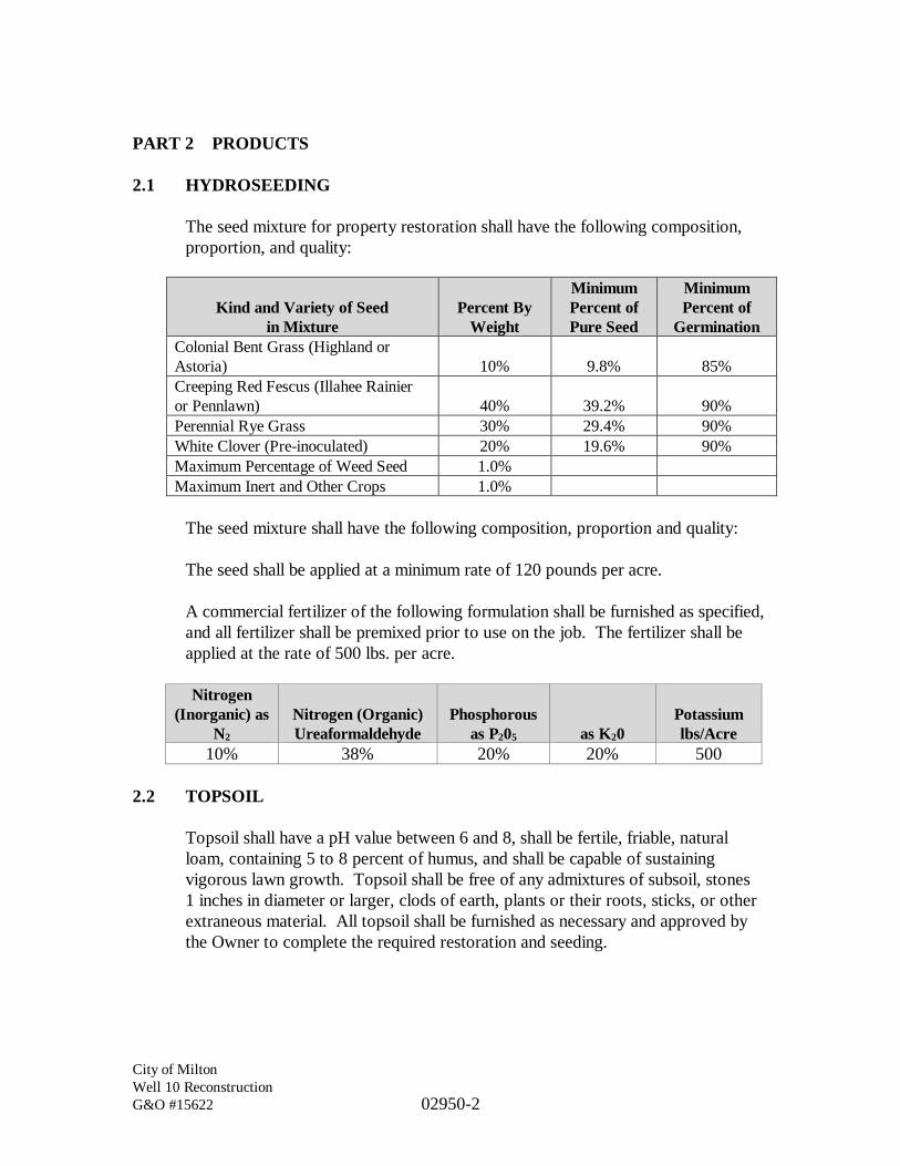
City of MiltonWell 10 ReconstructionG&O #15622 02950-2
PART 2 PRODUCTS
2.1 HYDROSEEDING
The seed mixture for property restoration shall have the following composition,proportion, and quality:
The seed mixture shall have the following composition, proportion and quality:
The seed shall be applied at a minimum rate of 120 pounds per acre.
A commercial fertilizer of the following formulation shall be furnished as specified,and all fertilizer shall be premixed prior to use on the job. The fertilizer shall beapplied at the rate of 500 lbs. per acre.
Nitrogen(Inorganic) as
N2
Nitrogen (Organic)Ureaformaldehyde
Phosphorousas P205 as K20
Potassiumlbs/Acre
10% 38% 20% 20% 500
2.2 TOPSOIL
Topsoil shall have a pH value between 6 and 8, shall be fertile, friable, naturalloam, containing 5 to 8 percent of humus, and shall be capable of sustainingvigorous lawn growth. Topsoil shall be free of any admixtures of subsoil, stones1 inches in diameter or larger, clods of earth, plants or their roots, sticks, or otherextraneous material. All topsoil shall be furnished as necessary and approved bythe Owner to complete the required restoration and seeding.
Kind and Variety of Seedin Mixture
Percent ByWeight
MinimumPercent ofPure Seed
MinimumPercent of
GerminationColonial Bent Grass (Highland orAstoria) 10% 9.8% 85%Creeping Red Fescus (Illahee Rainieror Pennlawn) 40% 39.2% 90%Perennial Rye Grass 30% 29.4% 90%White Clover (Pre-inoculated) 20% 19.6% 90%Maximum Percentage of Weed Seed 1.0%Maximum Inert and Other Crops 1.0%

City of MiltonWell 10 ReconstructionG&O #15622 02950-3
PART 3 EXECUTION
3.1 HYDROSEEDING
Areas that have been disturbed which are not covered by gravel, concrete, orpavement, shall receive topsoil, hydroseeding, fertilizing, and mulching. Theseareas shall be leveled, acceptable to Owner, existing topsoil broken up to a depthof 6 inches and hydroseeded. Graded areas shall receive 3 inches of topsoil priorto hydroseeding.
For those areas in which hydroseeding would be difficult, the Contractor mayrequest approval from the Owner to hand-apply the hydroseeding mix. Approvalshall be granted for hand-application only after reviewing and approving theprocedure that the Contractor recommends.
Seeding, fertilizing, and mulching shall be installed in conformance withSections 8-01 and 9-14 of the WSDOT Standard Specification.
Seeding, fertilizing, and mulching shall be installed using an approved typehydroseeder.
When weather conditions are not conducive to satisfactory results from seedingoperations, the Owner may order the work suspended and it shall be resumed onlywhen the desired results are likely to be obtained.
Areas that have received an application of mulching shall be inspected uponcompletion of the work and again on the completion of the application of seed andfertilizer.
3.2 HYDROSEEDING WATERING MAINTENANCE AND PROTECTION
The Contractor shall water, protect and care for all seeded areas until fullyestablished and healthy. Care shall include equipment and labor necessary toprovide sufficient watering of all planted areas until final acceptance.
Watering of hydroseeded areas shall be at the Contractor’s expense until newplantings are fully established.
The Contractor shall guarantee landscaping materials and workmanship for aperiod of 2 years following the date of project acceptance. During the 2-yearguarantee period, should any planted areas show signs of failure, such as dead ordying areas of grass or bare spots, the Contractor shall repair or replace alldeficient seeded areas to the satisfaction of the Owner. If any seeded areas or

City of MiltonWell 10 ReconstructionG&O #15622 02950-4
plants require replacement, the Contractor’s maintenance and guarantee periodapplicable to the replaced plants shall extend for an additional 1-year period afterthe time of the replacement.
The Contractor shall mow all newly established lawn areas a minimum of twomowings. The first mowing shall be performed only after an established andhealthy stand of grass is judged to have grown. The second mowing shall occurupon establishment of second healthy stand of grass (4 inches in height).
3.3 FINISHING AND CLEANUP
Before acceptance of the Project, all pipes, catch basins, and other appurtenancesshall be cleaned of all debris and foreign material. After all other work on theProject is completed and before final acceptance, the entire construction area shallbe neatly finished to the lines, grades and cross-sections shown on the Drawingsand as hereinafter specified.
In undeveloped areas, the entire area which has been disturbed by the constructionshall be shaped so that, upon completion, the area will present a uniformappearance, blending into the contour of the adjacent properties. All otherrequirements outlined previously shall be met. Slopes, sidewalk areas, plantingareas and roadway shall be smoothed and finished to the required cross-sectionand grade.
Upon completion of the cleaning and dressing, the Project shall appear uniform inall respects. All graded areas shall be true to line and grade as shown on thetypical sections and as required by the Owner.
All rocks in excess of 1-inch diameter shall be removed from the entireconstruction area and shall be disposed of the same as required for other wastematerial. In no instance, shall the rock be thrown onto private property.Overhang on slopes shall be removed and slopes dressed neatly so as to present auniform, well sloped surface.
All excess excavated material within the limits of the Project shall be removedentirely. All debris resulting from clearing and grubbing or grading operationsshall be removed and disposed.
Drainage facilities, such as inlets, catch basins, culverts, and open ditches, shall becleaned of all debris resulting from the Contractor’s operations.
All pavements, whether new or old, shall be thoroughly cleaned. Existingimprovements, such as Portland cement concrete curbs, curb and gutters, walls,

City of MiltonWell 10 ReconstructionG&O #15622 02950-5
sidewalks, and other facilities which have been sprayed by the asphalt cement shallbe cleaned to the satisfaction of the Owner.
Castings for manholes, monuments, water valves, lamp poles, vaults, and othersimilar installations which have been covered with the asphalt material shall becleaned to the satisfaction of the Owner.
3.4 CONSTRUCTION ACCEPTANCE
The Contractor shall protect and care for all seeded and sodded areas until fullyestablished and healthy. Care shall include equipment and labor necessary toprovide sufficient and continuous watering of all seeded areas until finalacceptance.
The Contractor shall guarantee landscaping materials and workmanship for aperiod of 2 years following the date of project acceptance. During the 2-yearguarantee period, should any seed areas show signs of failure such as dead ordying areas of grass or bare spots, the Contractor shall repair or replace alldeficient areas to the satisfaction of the Owner.
*** END OF SECTION ***

DIVISION 7
THERMAL AND MOISTURE PROTECTION

City of MiltonWell 10 ReconstructionG&O #15622 07110-1
SECTION 07110
BITUMINOUS DAMPPROOFING
PART 1 GENERAL
1.1 SCOPE
The work specified in this Section applies to the application of bituminousdampproofing on all vault wall surfaces, or as shown on the Plans and as specifiedherein.
1.2 RELATED WORK SPECIFIED ELSEWHERE
Section Item01300 Submittals02530 Utility Structures
1.3 REFERENCE STANDARDS
This Section references the latest revisions of the following documents:
Reference TitleASTM D41 Asphalt Primer Used in Roofing, Dampproofing and
WaterproofingASTM D1187 Test Method for Asphalt Base Emulsions for Use as
Protective CoatingsNRCA Waterproofing Manual
1.4 QUALITY ASSURANCE
Work shall be performed in accordance with NRCA Waterproofing Manual.
PART 2 PRODUCTS
2.1 APPROVED MANUFACTURERS
Bituminous dampproofing shall be W.R. Meadows or equal product foundationcoating.

City of MiltonWell 10 ReconstructionG&O #15622 07110-2
2.2 COLD ASPHALTIC MATERIALS
Cold asphaltic materials shall be in accordance with the following referencestandards:
Material Reference StandardAsphalt Emulsion Type II ASTM 1227-Type III.
PART 3 EXECUTION
3.1 EXAMINATION
The Contractor shall verify that surfaces are durable, and free of matter detrimentalto adhesion of dampproofing. The Contractor shall verify items which penetratesurfaces to receive dampproofing are securely installed.
3.2 PREPARATION
The Contractor shall protect adjacent surfaces not designated to receivedampproofing. The Contractor shall clean and prepare surfaces to receivedampproofing in accordance with manufacturer’s instructions. The Contractorshall not apply dampproofing to surfaces unacceptable to manufacturer orapplicator. Apply mastic to seal penetrations, small cracks, or minor honeycombin substrate. The Contractor shall maintain ambient temperatures above40 degrees F for 24 hours before and continuously during application untildampproofing membrane has cured.
3.3 APPLICATION
The Contractor shall prime surfaces in accordance with manufacturer’sinstructions. The Contractor shall apply cold bitumen with roller. Dampproofingshall be applied from 2 inches below finish grade elevation to top of footings. TheContractor shall seal items projecting through dampproofed surfaces with mastic.
3.4 SCHEDULE
The Contractor shall provide two coatings of asphalt dampproofing on all vaultwalls below grade.
*** END OF SECTION ***

DIVISION 8
DOORS AND WINDOWS

City of MiltonWell 10 ReconstructionG&O #15622 08310-1
SECTION 08310
METAL ACCESS HATCHES
PART 1 GENERAL
1.1 SCOPE
The work specified in this Section consists of furnishing and installing aluminumaccess hatches and accessories as shown on the Plans and as specified herein.
1.2 RELATED WORK SPECIFIED ELSEWHERE
Section Item01300 Submittals02530 Utility Structures
1.3 QUALITY ASSURANCE
Access hatches shall be guaranteed against defects in material and/or workmanshipfor a period of 5 years by the manufacturer.
PART 2 PRODUCTS
2.1 APPROVED MANUFACTURERS
Metal access hatches shall be Model “HD” as manufactured by LW ProductsCompany, or equal by Halliday or Bilco.
2.2 ACCESS HATCH
Fabricated aluminum access hatches shall support live H-20 wheel loads with amaximum deflection of 1/150th of the span. Door leafs shall be 1/4-inch aluminumdiamond plate with support beams on the underside. A 1/4-inch extrudedaluminum channel frame shall have a minimum 1-inch anchor flange around theperimeter with a 3/8” round neoprene gasket for a weather tight seal. A 1-1/2-inchaluminum drain coupling shall be integrated into the frame at the location shownon the Plans. A compression spring assembly shall be enclosed in telescopicstainless steel tubes to assist in opening and closing of the hatch cover. When adoor leaf is opened in a vertical position it shall automatically lock into place witha hold open arm. Closing the hatch shall be by an integral release handle. Doorhinges shall be heavy stainless steel and door latches shall shut with a stainless steelsnap lock. A removable turn handle shall be provided for access into the hatch
City of MiltonWell 10 ReconstructionG&O #15622 08310-2
cover and a threaded cover plug for when it is not in use. All hardware shall be300 series stainless steel.
PART 3 EXECUTION
Units shall be installed as specified herein and as shown on the Plans. The unitsshall be connected with drain piping as shown on the Plans, and shall be installedaccording to the manufacturer’s recommendations for safe and proper storage.
*** END OF SECTION ***

DIVISION 9
FINISHES

City of MiltonWell 10 ReconstructionG&O #15622 09900-1
SECTION 09900
PAINTING
PART 1 GENERAL
1.1 SCOPE
The work specified in this Section covers the furnishing and installation ofprotective coatings, complete-in-place. Special shop coatings and/or factory-applied finishes on manufactured or fabricated items may be specified elsewhere.Regardless of the number of paint coats previously applied, at least two field coatsof paint shall be applied to all surfaces unless otherwise specified herein. Fieldpainting is not required for factory prefinished equipment items such as pumps,blowers, motors, etc. Touchup of the factory applied coatings may be required.
The word “paint” as used herein shall be taken to include all protective coatingsand incidental materials as required with the exception that anodized aluminum orzinc galvanized coatings shall not be considered as paint.
Unless specifically noted otherwise in these Specifications or on the Plans, all workperformed under this Contract (both new work and modifications to existingfacilities) shall be painted. If an existing wall or ceiling (or similar surface) ismodified in someway, the entire wall or ceiling surface is to be painted.
1.2 RELATED WORK SPECIFIED ELSEWHERE
Section Item01300 SubmittalsDivision 15 Mechanical
1.3 REFERENCED STANDARDS
The following standards are referenced and shall be considered a part of theseSpecifications:
American National Standards Institute (ANSI):A159.1, Surface Preparation Specifications;Z53.1, Safety Color Code for Marking Physical Hazards
American Society for Testing and Materials (ASTM):D4263, Standard Test Method for Indicating Moisture in Concrete by thePlastic Sheet Method

City of MiltonWell 10 ReconstructionG&O #15622 09900-2
E84, Standard Test Method for Surface Burning Characteristics ofBuilding Materials
National Fire Protection Association (NFPA):101, Life Safety Code
Steel Structures Painting Council (SSPC):SP-1, Solvent CleaningSP-2, Hand Tool CleaningSP-3, Power Tool CleaningSP-5, White Metal Blast ClearingSP-6, Commercial Blast CleaningSP-7, Brush-off Blast CleaningSP-10, Near-White Blast CleaningSP-11, Power Tool CleaningSP-13 Surface Preparation for Concrete SurfacesVIS-89, Visual Standard
1.4 DEFINITIONS
A. PAINT
Includes fillers, primers, sealers, emulsions, oils, alkyds, latex, enamels,thinners, stains, epoxies, vinyls, urethanes, shellacs, varnishes and any otherapplied coating specified within these Specifications or shown on the Plans.
B. FINISHED ROOM OR SPACE
One that has a finish called for on Room Finish Schedule, or is indicated onthe Plans, or is specified herein, to be painted.
C. PAINTING COVERAGE RATE
Coverage’s expressed in SF/GAL/coat are the manufacturer’s publishedtheoretical coverage’s in square feet per gallon per coat.
1.5 SUBMITTALS
In addition to the general submittal requirements listed in Section 01300, thefollowing shall be submitted:
1. Written acknowledgment and certification that products submitted meetrequirements of standards referenced in this Section.

City of MiltonWell 10 ReconstructionG&O #15622 09900-3
2. Manufacturer’s application instructions for primer and finish coats.
3. Manufacturer’s surface preparation instructions.
4. Manufacturer’s full line of color samples for color selection by Owner.
5. If products being used are manufactured by a company other than thespecified reference standard, the Contractor must provide a completecomparison of the proposed products with the specified rerefence productsper Part 2.1 requirments, including application procedure, coverage rates,and verification that product is designed for intended use. Informationmust be provided that demonstrates that manufacturer’s products are equalto the performance standards of products manufactured by the TnemecCompany, which is the reference standard.
6. Manufacturer’s approval of protective coating systems applicator.
7. List of Applicator’s experience and qualifications. A minimum of 5-yearsof experience in the painting of wastewater treatment plant facilitiesrequired.
PART 2 PRODUCTS
2.1 APPROVED MANUFACTURERS
The following is an approved coating systems manufacturers list subject tocompliance with the Specifications contained herein:
1. Ameron Protective Coatings Division.2. Sherwin Williams.3. Tnemec Company.4. Or equal.
The specified coating shall be understood as establishing the type and quality ofcoating desired. Other manufacturers’ products will be accepted providedsufficient information is submitted to allow the Engineer to determine that thecoatings proposed are equivalent to those named. Proposed coatings shall besubmitted for review in accordance with these Specifications. Requests for reviewof equivalency will not be accepted from anyone except the Contractor, and suchrequests shall not be considered until after the Contract has been awarded.
No substitutions shall be allowed that change the number of coats, thickness orgeneric type of paint required. All materials shall be brought to the jobsite in the

City of MiltonWell 10 ReconstructionG&O #15622 09900-4
original sealed and labeled containers of the paint manufacturer and shall be subjectto inspection by the Engineer.
No coating materials other than those specified shall be brought to the jobsite.Thinners, driers and oils brought to the jobsite shall be only those recommendedand approved by the paint manufacturer.
All paint shall conform to the applicable air quality regulations at the point ofapplication. Any paint material which cannot be guaranteed by the manufacturerto comply, whether specified by product designation or not, shall not be used.
It shall be the responsibility of the Contractor to ensure the compatibility of thefield painting products which will be in contact with each other or which will beapplied over shop painted or previously painted surfaces. Paint used in successivefield coats shall be produced by the same manufacturer. Paint used in the first fieldcoat over shop painted or previously painted surfaces shall cause no wrinkling,lifting, or other damage to the underlying paint.
All paint shall be lead-free and mercury-free.
Tnemec Company products are the reference standard and Tnemec designationsfor product type are used herein. Requirements for an approved equal product arelisted below:
1. For approval of an equal manufacturer. The Contractor shall provide to theOwner in writing a detailed side-by-side comparison of the proposed equalProducts Characteristics, Performance Characteristics, and ApplicationConditions for each Tnemec coating specified in this specification. Forconsideration for approval this written comparison shall be certified andnotarized by an officer of the proposed manufacturer as true and correct.
2. For Products Characteristics this detailed side-by-side comparison shallinclude for example, but not limited to, Volume Solids, Weight Solids,VOC, Mix Ratio, Zinc Content in Dry Film (by Weight), Spreading Rateper coat, Drying Schedule, Shelf Life and Flash Point.
3. For Performance Characteristics this detailed side-by-side comparison shallinclude for example, but not limited to, Abrasion Resistance, CorrosionWeathering, Direct Impact Resistance, Dry Heat Resistance, Flexibility,Moisture Condensation Resistance, Pencil Hardness, Salt Fog Resistance,Slip Coefficient and Wet Heat Resistance
4. In addition to the detailed side-by-side comparison for approval of an equalmanufacturer, The Contractor shall provide to the Owner in writing five

City of MiltonWell 10 ReconstructionG&O #15622 09900-5
similar installations that have had the proposed or equal coating system anddate coating system was put into service. In addition the installationsnames, locations, and owner’s name with contact person and telephonenumber shall be provided.
5. For consideration for approval as an equal coating system the detailed side-by-side comparison shall be submit, with successful bidder’s Shop Drawingat the time of the Preconstruction Conference, along with any proposedmonetary adjustments to the contract price. As with all shop drawings, finalapproval rests with the Owner.
6. As a minimum standard any equal coating system shall have a 5-yearservice history on its coating system.
2.2 PAINT SYSTEMS
A. DUCTILE IRON PIPE AND FITTING MATERIALS(NON-IMMERSION)
1. Scope
This Section shall apply to exposed ductile iron pipe, fittings andmaterials that are not continuously or intermittently submerged.Continuously or intermittently submerged items are coveredelsewhere in this Specification.
2. Surface Preparation
Provide surface profile in accordance with ASTM D 4417,Method C
3. Coatings
Primer System:Coat OneProduct: Omnithane Series 1MDFT: 2.5 to 3.5 mils
Finish System:Coat OneProduct: Hi-Build Epoxoline Tnemec Series N69MDFT: 4 to 6 mils

City of MiltonWell 10 ReconstructionG&O #15622 09900-6
Coat TwoProduct: Endura-Shield III Tnemec Series 73MDFT: 3 to 5 mils
Total MDFT: 10.0 mils
B. GALVANIZED SURFACE TOUCHUP
1. Scope
This Section shall apply to all galvanized surfaces, which havereceived minor damage to the galvanized surface duringconstruction.
2. Surface Preparation
Power tool cleaning, SSPC-SP-3.
3. Coatings
Paint System:Product: Tnemec-Zinc Tnemec Series 90-97MDFT: 3 to 5 mils
Total MDFT: 3.5 mils
C. ALUMINUM BURIED IN CONCRETE - DISSIMILAR METALS
1. Scope
This Section shall apply to all surfaces, which are conducive tocorrosion due to interactions between dissimilar metals, or tochemical reactions, to include embedments in cast-in-place orprecast concrete or masonry grout. This Section applies toaluminum, hot-dipped galvanized steel, and any other metals thathave a dissimilar metals or chemical reaction concern when installedor embedded in concrete, or against concrete, mortar or grout.
2. Surface Preparation
Lightly sand with 150 grit sandpaper to degloss and roughensurfaces. Solvent cleaning, SSPC-SP-1.

City of MiltonWell 10 ReconstructionG&O #15622 09900-7
3. Coatings
Finish CoatProduct: Hi-Build Epoxoline Tnemec Series N69MDFT: 4 to 6 mils
Total MDFT: 4.0 mils
D. PAINTED WOOD AND WOOD TRIM
1. Scope
This Section shall apply to all exposed to view interior and exteriorwood and wood trim for buildings and structures. Color shall beselected by the Owner.
2. Surface Preparation
Wood surfaces shall be clean and dry. Sand wood as required.
3. Coatings
Primer System:Product: Electrogrip, Tnemec Series 151MDFT: 1.5 to 2 mils
Finish System:Coat One:Product: Envirocrete, Tnemec Series 156MDFT: 3 to 4 mils
Coat Two:Product: Envirocrete, Tnemec Series 156MDFT: 3 to 4 mils
Total MDFT: 9 mils
2.3 COLORS
A. GENERAL
Paint colors used for the finish coatings on process equipment, piping andbuilding surfaces shall conform to the following schedules. All finishesshall be glossy unless otherwise specified. Finish coatings, which are

City of MiltonWell 10 ReconstructionG&O #15622 09900-8
applied in the shop by the manufacturer, shall conform with this colorschedule wherever possible. Factory coatings which are damaged duringshipment or installation, or which are not of suitable color, as determinedby the Engineer, shall be recoated in the field in accordance with theseSpecifications.
Color samples shall be submitted to the Engineer for approval prior toapplication of any field coatings.
B. PIPING COLOR SCHEDULE
Piping Identification: Exposed piping and piping in accessible chases shallbe color coded as scheduled below.
Piping scheduled to be color coded shall be completely painted with theindicated colors. All other piping specified to be painted shall matchadjacent surfaces, unless otherwise approved by the Engineer.
Process Abbreviation Color of PipeDrain D Dark GrayDischarge to Waste DTW Light BlueSample S Same Color as ProcessWater W Dark Blue
PART 3 EXECUTION
3.1 GENERAL
It is the intent of these Specifications that materials and workmanship be providedsuch that the highest quality job is obtained. The completed work, prior toacceptance, must be free from runs, skips, mars and any other disfiguring mark dueto faulty workmanship or care of the completed work.
It is the responsibility of the Contractor to ensure that all surfaces are prepared inaccordance with the written recommendations and directions of the paintmanufacturer whose paint is applied.
Approval of conditions shall be obtained from the Engineer prior to applying anyor all coats of paint; however, such approval shall not relieve the Contractor of hisresponsibility of conformance with these Specifications and conformance with themanufacturer’s recommendations.

City of MiltonWell 10 ReconstructionG&O #15622 09900-9
It shall be the responsibility of the Contractor to prevent settling of dust or theoccurrence of other conditions detrimental to the finished quality of the job and torepair any damaged paint at no additional cost to the Owner.
Materials or equipment delivered with prime coats shall be touched up as requiredprior to the application of additional coating(s).
The Contractor shall apply each coating at the rate and in the manner specified bythe paint manufacturer. If material has thickened or must be diluted for applicationby spray gun, the coating shall be built-up to the same thickness achieved withundiluted material. Deficiencies in film thickness shall be corrected by theapplication of an additional coat(s) of paint.
No paint shall be applied when the surrounding air temperature, as measured in theshade, is below 40 degrees F. Paint shall not be applied to wet or damp surfacesand shall not be applied in rain, snow, fog or mist or when the relative humidityexceeds 85 percent. No paint shall be applied when it is expected that the relativehumidity will exceed 85 percent or that the air temperature will drop below40 degrees F within 18 hours after the application of the paint. Dew or moisturecondensation should be anticipated and if such conditions are prevalent, paintingshall be delayed until conditions improve to be certain that the surfaces are dryprior to application of paint. No paint shall be applied when the ambienttemperature is less than 5 percent F. above the dewpoint. Further, the day’spainting shall be completed well within advance of the probable time of day whencondensation will occur, in order to permit the paint film an appreciable dryingtime prior to the formation of moisture.
Manufacturer’s recommended drying time shall be construed to mean “undernormal conditions.” Where conditions are other than normal because of theweather or because painting must be done in confined spaces, longer drying timesshall be necessary. The manufacturer’s recommendations for recoating timeintervals shall be strictly adhered to.
Adequate ventilation, which will effectively remove solvents, shall be provided forproper drying of paints on interior surfaces.
3.2 MIXING AND THINNING
Paint shall be thoroughly mixed each time any is withdrawn from the container.Paint containers shall be kept tightly closed except while paint is being withdrawn.
Paint shall be factory mixed to proper consistency and viscosity for hot weatherapplication without thinning. Thinning will be permitted only as necessary toobtain recommended coverage at lower application temperatures. All thinning

City of MiltonWell 10 ReconstructionG&O #15622 09900-10
shall be done strictly in accordance with the manufacturer's instructions as well aswith the full knowledge and approval of the Engineer. In no case shall the wet filmthickness of applied paint be reduced, by addition of paint thinner or otherwise,below the thickness recommended by the paint manufacturer.
3.3 SURFACE PREPARATION
A. GENERAL
Surfaces shall be dry and thoroughly cleaned of foreign materials with alldefects filled or removed. All trades employed shall leave the surfaces oftheir work in such a condition that only minor cleaning, sanding and fillingis required of the painting trade for surface preparation.
Hardware, switchplates, machined surfaces, nameplates, lighting fixturesand all other surfaces not to be painted shall be removed or otherwiseprotected. Drop cloths shall be provided, where necessary, to avoidspotting of surfaces adjacent to the item being painted. Working parts ofelectrical equipment shall be protected from damage during surfacepreparation and painting operations.
Ferrous metal cleaning shall be in accordance with Steel StructuresPainting Council Specifications (SSPC).
Description SSPC
White Metal Blast Cleaning SP-5Commercial Blast Cleaning SP-6Brush-Off Blast Cleaning SP-7Near-White Blast Cleaning SP-10Preparation of Concrete SP-13
The words “blast cleaning” or equivalent phrases of equal intent shall betaken to refer to the applicable SSPC specification when used in the paintmanufacturer’s recommendations or these Specifications.
Hand tool cleaning shall be used when power tool cleaning is not possible.Hand and power tool cleaning shall be in accordance with SSPCSpecifications SP-2, SP-3 or SP-11, respectively.
The blast cleaning profile depth shall be not less than 1 mil or greater than2 mils. In the case of equipment to which the manufacturer applies aprimer coating in the shop after fabrication, the blast profile depth needs tobe as noted above.

City of MiltonWell 10 ReconstructionG&O #15622 09900-11
B. FERROUS METAL, GALVANIZED METAL AND HOLLOW METALSURFACES
The Contractor shall assure that fabrication, welding or burning iscompleted prior to the sandblasting operation. The Contractor shall chipor grind off flux, splatter, slag or other laminations left from welding. TheContractor shall remove all mill scale. The Contractor shall grind smoothrough welds and other sharp projections.
The Engineer reserves the right to accept preparation of these surfaces inaccordance with SSPC SP-3 for areas not practical or possible to sandblastto SSPC SP-6 requirements.
The Contractor shall apply prime coat on cleaned surfaces within 2 hoursof cleaning. The Contractor shall solvent clean galvanized surfaces inaccordance with SSPC SP-1.
C. WOOD
The Contractor shall sandpaper smooth, then remove dust. After primecoat has dried, seal all knots, pitch and resinous sapwood. The Contractorshall putty nail holes and minor defects prior to painting.
3.4 APPLICATION
A. GENERAL
The Contractor shall mix and apply coatings by brush, roller or spray inaccordance with the manufacturer’s installation instructions. Sprayingequipment shall be inspected and approved in writing by the coatingmanufacturer. The Contractor shall provide complete coverage’s to the milthickness specified. The thickness specified shall be dry film mil thickness.All paint systems are “to cover.” In situations of discrepancy between themanufacturer’s square footage coverage rates and mil thickness, milthickness requirements govern. When color or undercoats show through,the Contractor shall apply additional coats until paint film is of uniformfinish and color. The Contractor shall not apply consecutive coats until theEngineer has had an opportunity to observe and approve previous coats.
The Contractor shall apply materials under adequate illumination, shallevenly spread and flow on to provide full, smooth coverage, shall workeach application of material into corners, crevices, joints and other difficultto work areas, shall avoid degradation and contamination of blasted

City of MiltonWell 10 ReconstructionG&O #15622 09900-12
surfaces and avoid intercoat contamination, shall clean contaminatedsurfaces before applying next coat and shall immediately smooth out runsor sags, or remove and recoat entire surfaces. The Contractor shall assurethat preceding coats are dry before recoating, shall recoat within the timelimits specified by the coating manufacturer and shall allow coated surfacesto cure prior to allowing traffic or other work to proceed.
The Contractor shall coat all aluminum surfaces in contact with dissimilarmaterials. All fabricated and structural steel shall have prime coat(s)applied in the shop and finish coat(s) applied in the field.
During application of either prime or finish coats, brush coat all weldseams, edges, angles, fasteners and other irregular surfaces to insure amonolithic film, pinhole free surface. Finish coats of paint shall be uniformin color and sheen without streaks, laps, runs, drips, sags or missed areas.
B. PRIME COAT INSTALLATION
The Contractor shall prime all surfaces indicated to be painted, shall touch-up damaged primer coats prior to finish coats and shall assure field-appliedcoatings are compatible with factory-applied coatings. If coatings are notcompatible, and if approved in writing by the Engineer, the Contractor shallapply a 2-mil-thick universal barrier coat recommended by the paintmanufacturer prior to applying field coats or completely remove factorycoatings and reprime.
The Contractor shall prime ferrous metals bedded in concrete to aminimum of 1 inch below exposed surfaces. The Contractor shall brush orspray bolts, welds, edges and difficult access areas with primer prior toprimer application over the entire surface being coated.
C. FINISH SCHEDULE
All work performed under this Contract (both new work and modificationsto existing facilities) shall be painted. These items to be painted shallinclude:
1. Pipe and Appurtenances
2. Ferrous metals.
3. Exposed wood

City of MiltonWell 10 ReconstructionG&O #15622 09900-13
4. New machinery and equipment except:
a. Electrical panels;
b. Switchboards;
c. Switchgear;
d. Safety switches;
e. Motor starter equipment;
f. Busways;
g. Raceways.
The Contractor shall not paint the following elements unless specificallynoted on the Plans to be painted:
1. Stainless steel surfaces.
2. Exposed to view aluminum surfaces.
3. Galvanized metal surfaces.
4. Moving parts of mechanical and electrical units.
5. Code labels and equipment identification and rating plates.
3.5 FIELD QUALITY CONTROL
The Contractor shall be responsible for performing, testing and assuringconformance with all requirements of these Specifications.
The Contractor shall maintain daily records showing:
· Start date of work in each area.
· Date of application for each following coat.
· Moisture content and surface temperature of substrate. Also recordweather conditions, ambient air temperature and dew point.
City of MiltonWell 10 ReconstructionG&O #15622 09900-14
· Provisions utilized to maintain temperature and humidity of work areawithin paint manufacturer’s recommended ranges.
The Contractor shall measure the surface temperature of items to be painted withsurface temperature gauges specifically designed for such use. The Contractorshall measure substrate humidity with humidity gauges specifically designed forsuch use. The Contractor shall measure wet paint with wet film thickness gauges.The Contractor shall measure paint dry film thickness with a Mikrotest gaugecalibrated against the National Bureau of Standards “Certified Coating ThicknessCalibration Standards.” The Engineer may direct measurement of paint thicknessat any time during the project to ensure conformance with these Specifications. Asufficient number of dry film thickness measurements shall be made so that there isapproximately one measurement for each 100 square feet of surface area painted.
Where a wall or ceiling or other type of surface is disturbed and patched, theContractor shall repaint entire wall or ceiling. The Contractor shall provide wetpaint signs as necessary. The Contractor shall touch up damaged finish coats usingthe same material as specified for the finish coat.
At the conclusion of all painting activities, Contractor shall submit a painting fieldtest report to the Engineer showing the above information plus results of wet filmand dry film thickness tests. Provide four copies of final test report.
3.6 PAINT THICKNESS
All paint thicknesses specified herein are minimum dry film thickness (MDFT).The thickness of paint over metallic surfaces shall be measured with a magneticthickness gauge; paint thickness over wood or masonry shall vary in accordancewith surface texture, but in no case shall the manufacturer’s recommendedcoverage rate be exceeded. The minimum thicknesses given are total coatingthickness for the coating specified, including multiple coats of the same material,where applicable. Film thickness will be determined when dry by the Engineerwith a magnetic dry film thickness gauge. The thickness gauge will be calibratedwith test shims.
*** END OF SECTION ***

DIVISION 11
EQUIPMENT

City of MiltonWell 10 ReconstructionG&O #15622 11000-1
SECTION 11000
EQUIPMENT GENERAL PROVISIONS
PART 1 GENERAL
1.1 SCOPE
The provisions of this Section apply to all Sections of Divisions 11, 13, 15, and16, unless specifically revised therein.
The Contractor shall direct the attention of all subcontractors and suppliers ofequipment and related appurtenances for the work to the applicable provisions inthe Contract Provisions wherever they may occur.
1.2 RELATED WORK SPECIFIED ELSEWHERE
Section Item01300 SubmittalsDivision 11 EquipmentDivision 13 Special ConstructionDivision 15 MechanicalDivision 16 Electrical
1.3 STANDARDS FOR THE WORK
Pipe, fittings, wiring and supports shall be provided to produce complete,operable systems with all elements properly interconnected as shown in schematicdiagrams or to provide specified operations. If a specific dimensioned location isnot shown for interconnections or smaller system elements, the Contractor shallselect appropriate locations and show them on Shop Drawing submittals forreview.
Equipment and material shall be new and without imperfections and shall beerected in a neat and workmanlike manner; aligned, leveled, cleaned and adjustedfor satisfactory operation; installed in accordance with the recommendations ofthe manufacturers and the best standard practices for this type of work so thatconnecting and disconnecting of piping and accessories can be readily made andso that all parts are easily accessible for inspection, operation, maintenance andrepair. Oil and lubrication fittings shall be located clear of and away from guards,base, and equipment and within reach from the operating floor. In order to meetthese requirements with equipment as furnished, minor deviation from the Plansmay be made as authorized by the Engineer. All such minor deviations from thePlans that may include extending oil and lubrication fittings for accessibility andsafety shall be executed at no additional cost to the Owner.

City of MiltonWell 10 ReconstructionG&O #15622 11000-2
1.4 MANUFACTURER’S INSTRUCTIONS
The recommendations and instructions of the manufacturers of products used inthe work are hereby made part of these Specifications, except as they may besuperseded by other requirements of these Specifications.
1.5 SUBMITTALS
A. GENERAL
Product Submittals shall be provided to the Engineer for all equipmentspecified in Divisions 11, 13, 15, and 16, in accordance with Specification01300, this Section and the respective equipment specification section.
B. MANUFACTURER’S LITERATURE
Manufacturer’s literature shall be submitted for equipment, including, asapplicable, performance characteristics, fan curves and pump curves,motor data sheets and methods of assembly.
The following minimum requirements shall accompany all manufacturers’literature submittals:
1. Description of materials.
2. Rating data - Mechanical and Electrical as applicable.
3. Motor Data including bearing and enclosure information.
4. List of any special tools and/or spare parts required and to befurnished, if any.
5. Exceptions taken to the specification and detailed explanation whythe exception is being taken.
6. Additional specific information that is specified in the equipmentsections.
C. SHOP DRAWINGS
Shop Drawings shall be submitted showing sizes and arrangement ofequipment, foundations and anchor bolts required, control diagrams,wiring diagrams, pipe hanging details, ductwork layouts and connectionsto other work. The arrangement of mechanical equipment and appurtenant

City of MiltonWell 10 ReconstructionG&O #15622 11000-3
piping shown on the Plans may be varied as necessary to fit the certifiedmanufacturer’s installation drawings. However, the manufacturer’sdrawings shall not deviate from the Plans and Specifications as to location,size, type and design of equipment.
The following minimum requirements shall accompany all shop drawingsubmittals:
1. Overall dimensions.
2. Mounting arrangement and dimensions.
3. Connection sizes and orientation.
4. Capacity and location of lifting eyes.
5. Motor arrangement showing location of electrical connections.
6. Detail electrical wiring diagrams, showing component designationand rating, and the connection points and associated terminals andcable identification for connection to the process control system.
7. The Contractor shall ascertain the location of all electrical (powerand control) connections in order to properly orient electricalconduits.
D. FACTORY TEST REPORTS
Factory tests shall be performed for each piece of equipment wherespecifically called for in the Section specifying that equipment. Note thatfactory tests are inherent in many reference standards. The requirementfor a factory test in a referenced standard shall make that requirement apart of these Specifications. Conduct factory tests at the same speeds atwhich the equipment will operate in the field except as noted.
Where specifically noted, the Engineer may witness performance test.The Contractor shall inform the Engineer in sufficient time to allowarrangements to be made for witness of such tests. When non-witnessedtests are performed, certified results shall be supplied by the Contractor tothe Engineer.
Factory testing of pumps shall be done in accordance with therequirements and standards of the Hydraulic Institute. Tests of otherequipment shall conform to the requirements set forth in theseSpecifications.

City of MiltonWell 10 ReconstructionG&O #15622 11000-4
E. IDENTIFICATION OF DELIVERED EQUIPMENT
Each piece of equipment delivered to the project site shall be accompaniedby a completed form which will contain at least the following information:
1. Owner’s name and location of project.
2. Contractor’s name and subcontractor if applicable.
3. Name of item being submitted.
4. Specification reference by section, paragraph and page.
5. Data on item (manufacturer, general descriptive data, dimensions,size of connections, speeds, performance curves, serial number).
6. Motor data, type, voltage, frequency, phase, full load amperes,starting method, frame size, enclosure, insulation type, NEMACode letter, dimensions, service factor, serial number.
7. Date and signature of person certifying performance.
F. MANUFACTURER’S AFFIDAVITS
Equipment manufacturers, or their authorized representatives, shall eachsubmit a signed and dated written report with respect to his equipmentcertifying the following:
1. The equipment has been properly installed and lubricated
2. The equipment is in accurate alignment
3. The manufacturer was present when the equipment was placed intooperation
4. The manufacturer has checked, inspected, and adjusted theequipment as necessary
5. The equipment is free from any undue stress imposed byconnecting piping or anchor bolts
6. The equipment is not imposing any undue stress on any connectingmembers

City of MiltonWell 10 ReconstructionG&O #15622 11000-5
7. The equipment has been operated satisfactorily under full loadconditions
8. The manufacturer has inspected his equipment during theoperational demonstrations and system validation tests to theextent specified
9. The equipment is fully covered under the terms of the guarantee
PART 2 PRODUCTS
2.1 DESIGN
All equipment shall be designed for the service intended, of rugged construction,of ample strength for all stresses which may occur during fabrication,transportation, erection and during continuous or intermittent operation, shall beadequately stayed, braced and anchored, and shall be installed in a neat andworkmanlike manner. Appearance, safety, and utility shall be given considerationin the design of equipment. Materials of construction shall be cathodicallycompatible.
2.2 STANDARD REQUIREMENTS
A. MATERIALS
Design, fabricate and assemble equipment and systems with new materialsand in accordance with acceptable engineering and shop practices.Manufacture individual parts to standard sizes and gauges so repair partscan be installed in the field. Make like parts of duplicate unitsinterchangeable. Do not place equipment in service at any time prior todelivery except as required for factory or shop tests.
B. UNIFORMITY
Unless otherwise specified, equipment or material of the same type orclassification used for the same purpose shall be the product of the samemanufacturer and shall be the same model.
C. STANDARDS
Provide equipment and materials suitable for service conditions andmeeting standard requirements of ANSI, ASME, AWWA, ASTM,NEMA, UBC, NPC, UL and OSHA.
City of MiltonWell 10 ReconstructionG&O #15622 11000-6
2.3 LUBRICATION
Provide lubricants of types recommended by equipment manufacturers, inquantities sufficient for a minimum of 1-year’s consumption prior to completion,testing and final acceptance.
2.4 EQUIPMENT BASES AND BEDPLATES
Mount equipment assemblies on a single heavy cast iron or welded steel bedplateon a grout or concrete base unless otherwise shown or specified. Provide basesand bedplates with machined support pads, vibration pads, tapered dowels foralignment or mating of adjacent items, adequate openings to facilitate grouting,and openings for electrical conduits. Corners shall be rounded or chamfered andground smooth. Continuously weld seams and contact edges between steel platesand shapes, and grind welds smooth. Do not support machinery or piping onbedplates other than that which is factory installed. Provide leveling screws inequipment bases and bedplates to aid in leveling prior to grouting.
2.5 ANCHORS AND FASTENERS
Each equipment manufacturer shall furnish the required anchor bolts, nuts andwashers of adequate design for securing bases and bedplates to concrete bases.Provide anchor bolts of length to allow for 1-1/2 inch of grout under baseplatesand adequate anchorage into structural concrete unless otherwise shown orspecified. The manufacturer shall submit to the Engineer design calculationsregarding recommended sizing and type of anchor bolts, nuts, and washers forsecuring the equipment, in accordance with the project seismic requirements.
Anchor and assembly bolts and nuts shall be of ample size and strength for thepurpose intended. All nuts, bolts and washers shall be Type 316 stainless steel.All leveling nuts shall be Type 316 stainless steel.
All motor-driven equipment shall be furnished with cast-in-place anchor bolts ordrilled-in anchors set with epoxy adhesive. Do not provide expansion typeanchors for motor-driven equipment, or equipment or piping subject to vibration.
Expansion type anchors are not to be used for any submerged applications unlessspecifically noted on the Plans.
Anchor all non-motor-driven equipment with cast-in-place anchor bolts or drilled-in anchors set with epoxy adhesive except that, where specifically allowed bynote on the Plans, expansion type anchors may be used.
City of MiltonWell 10 ReconstructionG&O #15622 11000-7
2.6 ELECTRICAL COMPONENTS
Equipment shall be manufactured, fabricated and installed in a manner whichpermits conduit connection to electrical power and control equipment from belowthe connection point, terminal box, or connection box without offsets or bendssuch that the conduit will drain away from the equipment.
Electric motors, control panels, accessories, etc., shall conform to therequirements of Divisions 11, 12, 13, 15 and Division 16, Electrical.
If any motor fails during the warranty period, the Contractor shall replace themotor with a new motor. Rewinding a failed motor shall not be acceptable.
All electrical components shall be recognized or labeled and listed by arecognized electrical testing laboratory for the application, or approved by theWashington State Department of Labor and Industries for installation on theProject.
2.7 MOTOR PROTECTIVE DEVICE COORDINATION ANDDOCUMENTATION
The Contractor shall maintain a spreadsheet or database list of the motorcharacteristics that are necessary to size, select, and/or set the various motorprotective devices, such as thermal overloads, breaker trip devices, motorprotection relays, etc. This list shall also include any additional informationneeded to set-up, program or adjust the variable frequency drive which servesmotor driven equipment such as minimum speed, acceleration, etc. The list shallbe sent with each equipment submittal for motor driven equipment and shall beupdated to reflect the motor information for the submitted equipment
The Contractor shall record the size and/or settings of each motor protectivedevice at the time of startup and after any subsequent adjustments on the motorcharacteristics list described in the preceding paragraph.
In addition, the Contractor shall take a digital photo of each motor nameplatewhen the motor arrives at the jobsite. Each digital photo shall be emailed to theEngineer, noting any discrepancy between the motor nameplate data and thesubmitted motor data.
2.8 NAMEPLATES/DATA PLATES/IDENTIFICATION
Each piece of equipment and its driver shall be furnished with a stainless steelmetal nameplate fastened to the item in an accessible position. This nameplateshall contain the manufacturer’s name, equipment rating, capacity, size, model,serial number and speed. Data for motors shall be NEMA standard. All

City of MiltonWell 10 ReconstructionG&O #15622 11000-8
information written or printed shall be in English. Each item of equipment shallbear a different serial number. Measurement units shall be given for ratings andcapacity.
Nameplates for tanks and pressure vessels shall give working pressure, testpressure, vessel plate thickness and ASME Code data.
Each piece of rotating equipment shall have a direction of rotation arrow.
Each piece of equipment shall be labeled using a plastic laminate label with thefunctional name and number of the equipment shown on the Plans or provided bythe Engineer. Name and number shall correspond to those used on Motor ControlCenters and Panels.
Labels shall be fastened to the equipment base or other acceptable location. Theletters shall be at least ½-inch high with a border trim on all sides not less than ¼-inch. Color shall be green background with white letters. Fasteners shall be brassor stainless steel screwed into inserts, anchor shields or tapped holes in equipmentor base.
Units of measure shall be shown on the indicating and totalizing dials of allmeters, gauges and other measuring devices.
2.9 PROTECTION AGAINST ELECTROLYSIS
Where dissimilar metals are used in conjunction with each other, suitableinsulation shall be provided between adjacent surfaces so as to eliminate directcontact and any resultant electrolysis. The insulation shall be bituminousimpregnated felt, heavy bituminous coatings, non-metallic separators or washers.Connections of dissimilar piping materials shall utilize dielectric unions, flanges,couplings or bushings.
2.10 PAINTING
Painting of all equipment shall be in accordance with Section 09900 of theseSpecifications.
PART 3 EXECUTION
3.1 INSPECTION
Inspect each item of equipment for damage, defects, completeness, and correctoperation before installing. Inspect previously installed related work and verifythat it is ready for new equipment installation.

City of MiltonWell 10 ReconstructionG&O #15622 11000-9
3.2 PREPARATION
Prior to installing equipment, ensure that the areas are clean and that concrete ormasonry operations are completed. Maintain the areas in a broom-clean conditionduring installation operations. Clean, condition, and service the equipment inaccordance with the Operation and Maintenance Instruction Manuals and specificrequirements included in applicable Sections of these Specifications.
3.3 SPARE AND LOOSE PARTS
Prior to equipment startup provide an inventory of spare and loose parts suppliedunder the project. Turn over inventory and parts to the Owner. The Owner’swritten acknowledgment of receipt is required for project completion. Looseparts are defined as items such as special tools, keys, safety equipment, andportable equipment.
3.4 INSTALLATION
A. EQUIPMENT
Equipment shall conform to the approved submittals and Operation andMaintenance Instruction Manuals. Employ skilled craftsmen experiencedin installation of the types of equipment specified. Use specialized toolsand equipment, such as precision machinist levels, dial indicators, gauges,and micrometers, as applicable. Produce acceptable installations free ofvibration or other defects.
B. ANCHOR BOLTS
Deliver bolts with templates or setting drawings and verify that bolts arecorrectly located before structural concrete is placed. Prior to assembly, theContractor shall coat all stainless steel bolts and nut threads with anti-seizingcompound.
C. BASE AND BEDPLATE GROUTING
Do not place grout until initial fitting and alignment of connected piping iscompleted. Level and align equipment on the concrete foundations, thenentirely fill the space under base or bedplates with grout. Bevel exposedgrout at 45-degree angle, except around exposed grout at horizontal surfacesfor drainage. Trowel or point exposed grout to a smooth, dense finish anddamp cure with burlap for 3 days. When grout is fully hardened, removejacking screws and tighten nuts on anchor bolts. Check the installation foralignment and level, and perform corrective work as required to conform to

City of MiltonWell 10 ReconstructionG&O #15622 11000-10
the tolerances given in the applicable Operation and MaintenanceInstruction Manual.
The Contractor shall make an allowance of at least 1-1/2 inches for groutunder the equipment bases, whether or not shown on the Plans. Shims usedto level and adjust the bases shall be steel. Shims may be left embedded inthe grout, in which case they shall be installed neatly and so as to be asinconspicuous as possible in the complete work. Unless otherwiseauthorized, all grout shall be a non-shrink, non-metallic grout as stated inSection 03300.
Where practicable, the grout shall be placed through the grout holes in theequipment base and worked outward and under the edges of the base andacross the rough top of the concrete foundation to a peripheral form soconstructed as to provide a suitable chamfer around the top edge of thefinished foundation.
3.5 EQUIPMENT STARTUP AND ADJUSTMENT
The Contractor, at his/her own expense, shall arrange for an authorized factory-trained representative of the company or companies supplying the various items ofequipment to:
· Supervise the equipment installation in accordance with theOperation and Maintenance Instruction Manual.
· Be present when the equipment is first put into operation.
· Inspect, check, adjust as necessary, and approve the installation.
· Repeat the inspection, check and adjust until all trouble or defectsare corrected and the equipment installation and operation areacceptable.
· Witness and supervise operational demonstrations and systemvalidation tests to the extent specified.
· Prepare and submit the specified Manufacturer’s Affidavit.
The representative shall be experienced and knowledgeable regarding the equipmentbeing tested.
The Contractor shall give initial lubrication to all equipment in accordance with themanufacturer’s recommendations.

City of MiltonWell 10 ReconstructionG&O #15622 11000-11
The manufacturer shall provide a formal test procedure and report forms forrecording data. The Contractor shall submit the report forms to the Engineer priorto operational testing.
All equipment shall be field tested and demonstrated to the Engineer that properoperation and capacity have been fully complied with. For pumps, this shall includemeasurement of suction and discharge pressure at the pump and measurement ofpumping rate by volumetric means, or through a suitably calibrated meter for twopoints on the performance curve. Current draw and voltage on the motor for eachphase shall be measured for each pumping rate measurement. For two-speed pumps,such tests shall be conducted at both speeds. For variable speed pumps, blowers orfans, these tests shall be conducted at minimum and maximum speeds and at thespecified duty point.
The Contractor shall furnish and test equipment or measuring devices (includingportable flow meters) required that are not part of the permanent installation. Testsfor variable speed pumps, blowers, and other equipment shall be performed at 60 Hzand at the initial anticipated flow or capacity levels.
The field test shall demonstrate under all conditions of operation that theequipment:
· Has not been damaged by transportation or installation.
· Has been properly installed.
· Has no mechanical defects.
· Is in proper alignment.
· Has been properly connected.
· Is free of overheating of any parts.
· Is free of vibration in excess of the limits in Section 11010.
· Is free of excessive noise.
· Is free of overloading of any parts.
· Shall operate as specified with the specified control system.
· Is free of critical speeds as specified in Section 11010.

City of MiltonWell 10 ReconstructionG&O #15622 11000-12
In addition, the entire facilities shall be demonstrated to be in full operating orderprior to the acceptance of the work. Should any equipment or part thereof fail tooperate as intended, it shall be immediately removed and replaced, all at theContractor’s expense.
Equipment start-up and adjustment shall take place before instruction of the Owner’spersonnel is performed.
3.6 INSTRUCTION OF OWNER’S PERSONNEL
Conduct an instruction program for up to six operations personnel designated bythe Owner in accordance with Specification Section 01800. Furnish the servicesof qualified instructors from the various equipment manufacturers for the durationspecified in each specific Section. Include instruction covering basic systemoperation theory, routine maintenance and repair, and “hands on” operation ofequipment.
Provide the instruction program at the Owner’s convenience before contractcloseout. The Contractor shall audio- and video-record all training sessions, andalso provide the Owner with any audio-visual training materials the manufacturerutilizes (i.e., DVDs, PowerPoint presentations, videocassettes etc.). Cost ofinstruction and audio-visual training materials shall be included in the bid pricefor the equipment.
*** END OF SECTION ***

City of MiltonWell 10 ReconstructionG&O #15622 11211-1
SECTION 11211
SUBMERSIBLE WELL PUMP
PART 1 GENERAL
1.1 SCOPE
The work specified in this Section includes furnishing, installing, and testing asubmersible well pump and pitless well adapter.
The Contractor and pump manufacturer’s representative shall coordinate allaspects of supplying, delivering, installing, and testing the pumps to comply withthe requirements of these Specifications as shown on the Plans and as specifiedherein.
1.2 RELATED WORK SPECIFIED ELSEWHERE
Section Item01300 Submittals11000 Equipment General Provisions15050 Piping Systems15100 ValvesDivision 16 Electrical
1.3 EQUIPMENT LIST
The following equipment shall be provided:
Item Equipment NumberWell No. 10 10 WP 01
1.4 DESIGN CONDITIONS
The submersible pump covered by these Specifications shall have the motormounted below the pump sections as herein described and further indicated on thePlans.
The submersible pump assembly shall be comprised of a submersible motorcombined with a vertical turbine pump assembly of multi-stage configuration. Thepump assembly shall be driven by the motor shaft through a coupling, with powerbeing supplied to the motor through a submarine type cable. The cable shall bestrapped to the riser column.
City of MiltonWell 10 ReconstructionG&O #15622 11211-2
The submersible pump shall be capable of meeting the following performancerequirements.
Well Designation Well No. 10Maximum Pump and Motor Speed 1,800 rpmMotor Horsepower 150 hpRated Capacity (Design Point) 1,000 gpmTotal Dynamic Head 435 feetMinimum Efficiency at Design Point (Pump Only) 83%NPSH Required at Rated Capacity 13 feetShutoff head, Maximum 560 feetPump Discharge Pipe Size 8-inchWell Riser Column Size 8-inch
1.5 SUBMITTALS
Submit shop drawings for the pump together with sufficient data to show that theequipment conforms to the Specification requirements. Show that the pump anddriver supports and anchorage will resist seismic forces per the IBC. Submitinformation on the moment of inertia of the rotating elements in units of pounds-feet squared including weight and radius of gyration.
1.6 PUMP WARRANTY
The pump manufacturer shall warrant the unit being supplied to the Owner againstdefects in workmanship and material for a period of two years. The warranty shallbe in printed form. The warranty period shall begin on the date of final acceptanceby Owner of the pump installation.
PART 2 PRODUCTS
2.1 APPROVED MANUFACTURERS
The submersible pump shall be a 8-stage Model 11MH as manufactured byHydroflo Pumps, or approved equal.
Any modifications to the mechanical, structural, electrical, instrumentation andcontrol, and other portions of the work that may be required to adapt the generallayout and details shown on the Plans to the equipment actually furnished shall beat no additional cost to the Owner. All necessary design revisions shall be made atthe Contractor’s sole expense. All redesign information prepared by theContractor shall be submitted for review prior to incorporating the redesign intothe work.

City of MiltonWell 10 ReconstructionG&O #15622 11211-3
2.2 FACTORY TESTING
Perform certified factory performance tests in accordance with Hydraulic InstituteStandards for each pump.
Tests shall be sufficient to determine the curves for capacity, kilowatt input, waterhorsepower, and overall efficiencies for heads from shutoff to a point beyond theminimum specified head for the pumping units. Sufficient test data shall besubmitted to enable computation and plotting of curves for brake horsepower andpump efficiency for full range operation. A minimum of four points, includingshutoff, shall be taken for each test run. One point of the four shall be taken asnear as possible to the rated condition of head and discharge. One point shall betaken near the maximum capacity point of the standard curve. Discharge shall beexpressed in gallons per minute on the curves.
Six certified copies of the curves showing the results of the factory shopperformance and hydrostatic tests, shall be furnished to the Owner for approval.Shipment of the pumping units shall not be made until the Owner has approved thetest data curves.
2.3 SUBMERSIBLE WELL PUMP
Pump bowls shall be manufactured from close grain ASTM A48, Class 30, castiron. They shall be flanged type construction and free of blow holes, sand holes orother defects and shall have epoxy enamel lined waterways.
Pump impellers shall be manufactured from investment cast ASTM A296, Type304 stainless steel. They shall be enclosed-type impellers, and shall be free fromdefects, machined, backfilled and balanced after the casting process. They shall besecurely fastened to the bowl shaft with stainless steel taper locks.
Bowl shaft shall be manufactured from pump shaft quality (PSQ) ASTM A582,Type 416 stainless steel. It shall be machined and straightened to within a 0.002"to 0.004" tolerance.
The motor adapter shall be manufactured from ASTM A536, Class 65, ductile ironand shall be sized and designed by the pump manufacturer to handle the weightand torque of the submersible motor. The water inlet shall be above the motorbracket bearing. The inlet area shall be sized with a net open area of four times theimpeller eye opening and shall be protected by a Type 304 stainless steel screen ofa sufficient mesh size to prevent passage of particles which are too large to passthrough the pump.

City of MiltonWell 10 ReconstructionG&O #15622 11211-4
The submersible discharge shall be manufactured from ASTM A536, Class 65,ductile iron and shall be sized and designed by the pump manufacturer to handlethe weight and torque of the submersible motor and pump assembly. Thedischarge shall be threaded with NPT threads and have an extra-long top bearing.
All submersible pump hardware shall be Type 416 stainless steel.
2.4 MOTOR
The stator core of the motor shall be formed from non-aging silicon steellaminations and secured in a heavy steel tube. The stator coils shall be placed insemi-closed slots and secured by heat resisting insulating wedges. The squirrelcage rotor shall be stack shrunk on the shaft making a solid indestructibleassembly. The rotor and shaft shall be accurately machine and dynamicallybalanced to insure vibrationless operation. Bronze sleeve bearings shall beprovided at each end of the rotor. A pivot or solid shoe thrust bearing shall carrythe weight of all rotating parts and the hydraulic thrust of the pump. The motorshall have a thrust bearing with capacity of 7,200 pounds and continuous upthrustcapacity of 4,000 pounds. Upthrust bumpers shall not be acceptable. The statorand motor casing shall be of steel and the upper bearing bracket of close grainedcast iron, containing a small percentage of nickel to increase the density. Themotor shaft through the seal and the motor coupling shall be stainless steel.
The motor may be water cooled or oil cooled. Oil used to cool, insulate, orlubricate the motor must be a medicinally pure mineral oil of high dielectric,strength and be circulated by an internal pump.
2.5 POWER CABLE
The power cable from the control panel or junction box to the motor shall be ULapproved, submarine type power cable consisting of three-stranded, copperinsulated conductors of proper size to carry the full load motor amperes at ratedvoltage or to keep voltage drop between motor and control panel below 3 percent,whichever is larger. Each conductor shall be enclosed in an insulating watertightsynthetic rubber or plastic jacket: the whole to be enclosed in an outer syntheticrubber of plastic jacket which shall be impervious to oil. The power cord shall besealed, not only by use of a cord grip, but shall have individual conductors sealedinto the cord cap assembly with an epoxy sealing compound to insure a watertightcable connection at the surface plate assembly. The power cable shall besupported on the riser column by means of cable clamps at intervals not exceeding15 feet.

City of MiltonWell 10 ReconstructionG&O #15622 11211-5
2.6 COLUMN PIPE
The column pipe shall be of ASTM A53 grade B steel pipe. Column pipe sectionsshall be interchangeable and not over 10 feet in length. Column sections shall bescrewed. The column pipe shall be galvanized.
2.7 ATTACHMENT ITEMS
Straps to hold PVC piping shall be either stainless steel or manufactured plasticstraps, suitable for this particular installation and the possible difficulties that maybe encountered upon pump and column installation within the close tolerances tobe encountered.
2.8 PITLESS WELL ADAPTER
Pitless well adapters shall be factory assembled and tested before shipment to thesite. Pitless units shall conform to the Recommended Standards for Water Works,Great Lakes Upper Mississippi River Board of State Public Health. Pitless unitsshall be the Heavy Duty “HD” Model manufactured by MAADD Midwest, orequal.
The top of the unit shall include a watertight cap that shall be secured to the pitlesscasing with a compression gasket. The top of the cap shall be removable withoutaffecting the sealed conduit or wiring and shall include a protected downwardfacing stainless steel screened well vent with pipe nipple. Construction of the capand well vent shall be of heavy duty gray cast iron with an epoxy finish.
The upper casing of the pitless unit shall provide a watertight connection from thedischarge body to the well cap. The unit’s discharge port center line upper casingelevations shall be as shown on the Plans.
The spool shall include an 8-inch NPT per ANSI B 1.20.1 male or female droppipe connection and shall be constructed of lead-free galvanized heavy duty graycast iron, ductile iron, or steel. The spool shall have O-ring grooves machined intothe spool to retain and protect the O-rings when setting or pulling the system. TheO-ring seals shall be constructed of neoprene or equivalent. The spool shall alsobe designed to accommodate probe tubes or water samplers and include NPT portsfor discharge pressure taps.
The discharge body shall be constructed of lead-free galvanized ductile iron orlead-free galvanized steel and shall be designed to prevent distortion of the body ormovement of the spool due to vertical movement of discharge pipe. The minimumI.D. of the discharge body shall be equal to or greater than I.D. of the well casing.

City of MiltonWell 10 ReconstructionG&O #15622 11211-6
The pitless unit spool shall include a hold down mechanism to prevent rotation ofthe pitless spool relative to the discharge body at full rated locked rotor torque ofthe submersible pump motor. The spool shall also include a lift out pipe and bailcapable of supporting the full weight of the suspended pump and column assemblyincluding the contained water.
PART 3 EXECUTION
3.1 INSTALLATION
Install equipment in strict conformance with the manufacturer’s installationinstructions. Align pumps and motors after installation. In no event shall the risercolumn be bent (curved) out of straight alignment upon installation within the well.
The pump installer shall be responsible for the ordering and installation of allapproved materials to be used in the pump installation.
The subcontractor installing the pump/column and associated equipment shall beresponsible for alignment of all of the installed equipment and setting the lateraladjustments.
The equipment, its installation, and the workmanship shall conform to WashingtonState standards, particularly “Minimum Standards for Construction andMaintenance of Wells,” Chapter 173-160 WAC, effective March 13, 1990, asprepared by Washington State Department of Ecology. Included in this standardare the requirements of disinfection of the well itself and the equipment to beinstalled therein shall be disinfected per AWWA C654. The completed well shallconform in all respects with the above stated standards.
3.2 FIELD TESTING
Field test all pumps for conformance with the design conditions in this Section.
After installation within the pump house, the pumping unit shall be subjected to afield running test under actual operating conditions. The field test shall be made bythe Contractor and pump supplier as required by Sections 01800 and 11000.
1. Has not been damaged by transportation or installation.2. Has been properly installed.3. Has no mechanical defects.4. Is in proper alignment.5. Has been properly connected.6. Is free of overheating of any parts.7. Is free of all objectionable vibration, as specified in Section 11010.

City of MiltonWell 10 ReconstructionG&O #15622 11211-7
8. Is free of excessive noise.9. Is free of overloading of any parts.10. Shall operate as specified with the specified control system.
Any defects in the equipment or failure to meet requirements of the Specificationshall be promptly corrected by the Contractor and/or pump supplier.
Disinfection of the well and its equipment is more specifically covered by theAWWA Standard C-654, “Disinfection of Wells.” Section 4 thereof and otherrelated Sections apply to chlorination of permanent equipment and material used inwells. The final disinfection test of the well shall be a bacteriological testconforming with the requirements of Section 6 thereof. Well water shall not bepumped into the public water system until the well and water are approved fordomestic use as approved by State Department of Health and the Owner.
3.3 MANUFACTURER’S SERVICES
The Services of a factory- trained representative of the equipment manufacturershall be provided by the Contractor. Services shall include 2 days (two visits)onsite for the supervision of equipment startup, testing and instruction of theOwner’s personnel in the operation and maintenance of the equipment. One trip (1day) shall be for installation inspection, certification and testing; and one trip (1day) shall be for startup and training. Instruction and training of the Owner’spersonnel shall not take place until startup is completed and the equipment is fullyoperational and shall be at a time and location agreed to by the Owner. The costof these services shall be included in the bid price.
*** END OF SECTION ***

DIVISION 13
SPECIAL CONSTRUCTION

City of MiltonWell 10 ReconstructionG&O #15622 13127-1
SECTION 13127
WOOD POST FRAMED CANOPY
PART 1 GENERAL
1.1 SCOPE
The work specified in this Section consists of work necessary for design,fabrication, erection, and painting of the wood post framed building, as shown onthe Plans and as specified.
1.2 RELATED WORK SPECIFIED ELSEWHERE
Section Item01200 Measurement and Payment01300 Submittals01400 Quality Control
1.3 REFERENCES
This Section references the latest revisions of the following documents:
Reference Title
IBC International Building CodeASCE 7 Minimum Design Loads for Buildings and Other StructuresALSC PS-20 American Lumber Standard Committee: American Soft
Wood Lumber StandardAWC NDS American Wood Council National Design Specification for
Wood ConstructionAWPA U1 American Wood-Preservers’ Association (AWPA) Standard
1.4 SUBMITTALS
Submit in accordance with provisions of Section 01300.
A. MANUFACTURER’S LITERATURE
Where the contents of submitted literature includes data not pertinent tothe submittal, the portion(s) of the contents being submitted for theEngineer’s review shall be clearly indicated.

City of MiltonWell 10 ReconstructionG&O #15622 13127-2
B. SHOP DRAWINGS
Shop drawings shall be submitted in the form of black-line prints of eachsheet.
All shop drawings shall be accurately drawn to a scale sufficiently largeenough to show pertinent features and method of connection or joining.On all shop drawings, figure dimensions shall be used as opposed to scaleddimensions.
C. COLOR AND MATERIAL SAMPLES
Provide manufacturer’s standard selection of not less than ten colors.
D. DESIGN CALCULATIONS
Provide a minimum of five copies of design calculations. Designcalculations shall be complete, concise, and in an easy to read format. Alicensed Structural Professional Engineer of the State of Washington shallstamp all design calculations.
1.5 DESIGN REQUIREMENTS
A. DESIGN ANALYSIS
Criteria and definitions shall be in accordance with the 2015 InternationalBuilding Code (IBC) and the American Society of Civil Engineers Standard7-10 (ASCE 7) for all loads and load combinations, including, but notlimited to, dead, live, snow, seismic, and wind loads.
The building shall be a wood building with steel siding and roofing asshown on the Plans.
All wood members shall be pressure treated.
B. DESIGN LOAD CRITERIA
The post framed building shall be designed for the following minimum live,wind, dead, and auxiliary loads.
1. Dead Loads:
Building Materials To be verified by manufacturerMechanical and Electrical System 5 PSF
City of MiltonWell 10 ReconstructionG&O #15622 13127-3
2. Live Loads:
Snow, minimum 25 PSF Important Factor 1.1
3. Lateral Loads:
Seismic:
Occupancy Category IIIImportance Factor I = 1.25Mapped Spectral Response SS = 127% gAcceleration S1 = 49% gSite Class E
Wind:
Wind Speed (Ultimate) 115 mphImportance Factor Iw = 1.0Exposure B
Wind load pressures shall be proportioned and applied as horizontaland uplift forces as recommended by ASCE 7.
4. Auxiliary Loads:
Auxiliary loads are additional loads from mechanical equipmentunits. See Plans for approximate unit weights. Buildingmanufacturer shall verify the location and unit weights.
5. Foundation Data (IBC 2015 Table 1806.2):
Allowable Soil Bearing Pressure 1,500 PSFLateral Bearing 100 PSF/FT DepthCoefficient of Friction N/A
1.6 QUALITY ASSURANCE
A. INSTALLER’S QUALIFICATIONS
Installation of the post framed buildings and accessories shall be performedby installers with a minimum of 5-years experience in projects of thisnature.

City of MiltonWell 10 ReconstructionG&O #15622 13127-4
B. MANUFACTURER’S QUALIFICATIONS
Manufacturer shall have a minimum of 10-years experience in the designand fabrication of post framed buildings in the region where the work is tobe done.
C. REGULATORY AGENCY REQUIREMENTS
Comply with the 2015 International Building Code and local Building Coderequirements.
1.7 WARRANTY
The Post Framed Building System (roofing, siding, and related componentsprovided as part of the system) shall be warranted as described below againstmaterial and workmanship deficiencies, system deterioration caused by ordinaryexposure to the elements and service design loads, leaks and wind uplift damage.Any emergency temporary repairs conducted by the owner shall not negate thewarranties.
The Post Framed Building System shall be warranted by the Contractor for aperiod of 5 years against materials and workmanship deficiencies; systemdeterioration caused by exposure to the elements and/or inadequate resistance tospecified service design loads, water leaks, and wind uplift damage.
A. EXTERIOR MATERIAL FINISH WARRANTY
A manufacturer’s 30-year exterior material finish warranty on the factorycolored finish warranting that the finish, under normal atmosphericconditions at the site, will not crack, peel, delaminate; chalk; or changecolor. Liability under this warranty is exclusively limited to replacing thedefective coated material.
PART 2 PRODUCTS
2.1 APPROVED MANUFACTURERS
Subject to compliance with requirements, Manufacturers which may beincorporated in the work include, but are not limited to, the following:
Town and Country Post Frame Building (800) 824-9552
City of MiltonWell 10 ReconstructionG&O #15622 13127-5
2.2 MATERIALS
A. PRIMARY STRUCTURAL FRAMING MEMBERS
Primary structural framing shall include but is not limited to the following:roof purlins and trusses, wall girts and or studs, mezzanine framing, andsupport posts/columns.
Primary structural framing members shall comply with ALSC- PS 20 with applicable grading rules of inspection be the American LumberStandards Committee Board of Review. Provide dressed S4S lumber withminimum 19 percent moisture content at time of dressing and shipment.Framing lumber shall be Douglas Fir Larch No. 2 or better: or Hem Fir No.1 or better. Framing members shall be treated for weather protection inaccordance with AWPA U1.
B. CAST-IN-PLACE CONCRETE AND REINFORCING STEEL
1. Cast-in-Place Concrete:
Concrete shall have the following properties:
28-Day Strength fc = 3,500 PSIAir Entrainment 5 to 7 percentMaximum Sump 3 inches
Construction to be in accordance with ACI 318, “Part 2 – Standardfor Tests and Materials” and “Part 3 – Construction Requirements.”
2. Reinforcing Steel:
Welded Wire Fabric (W.W.F.) ASTM A82 and A185Deformed Bars ASTM A615, Grade 60
(Grade 40 for #3)
Unless otherwise noted on the Plans, minimum concrete cover forreinforcing bars shall be as follows:
Concrete Cast Against Soil = 3 inchesFormed Concrete Against Soil = 2 inchesWalls Exposed to Water, Sewage and Weather = 2 inchesWalls, columns and Beams Dry Condition = 1-1/2 inches

City of MiltonWell 10 ReconstructionG&O #15622 13127-6
C. ROOFING AND SIDING
Provide manufacturer’s standard roofing and siding as indicated on Plans.Provide available color samples for owner selection.
Provide necessary flashing and trims at rake, eave, corners, openings andridge panels or ridge caps as required to provide a finish appearance andweather-tightness. Panels, flashing, and trims shall be manufacturer’sstandard but not less than 26 gauge minimum.
D. CONNECTIONS
Connections shall be as recommended by the manufacturer to meet thedesign strength requirements.
E. GUTTERS AND DOWNSPOUTS
Provide gutters and downspouts as shown on Plans and as specified herein.Gutter and downspouts shall be attached to the roof panel usingmanufacturer’s standard fasteners. Gutter sections shall be lapped and allsplices and end closures shall be sealed for water tightness and thenfastened with trim fasteners. The complete gutter system color shall matchthe steel building.
F. SEALANT AND ACCESSORIES
Sealant shall be an elastomeric type containing no oil or asphalt. Exposedsealant shall be colored to match the applicable building color and shallcure to a rubber like consistency.
Flashing, trim, metal closure strips and curbs, fascia, caps, diverters, andsimilar metal accessories shall be the manufacturer’s standard products.Exposed metal accessories shall be finished to match the building finish.Molded closure strips shall be bituminous-saturated fiber, closed-cell orsolid-cell synthetic rubber or neoprene, or polyvinyl chloride premolded tomatch configuration of the roofing or siding and shall not absorb or retainwater.

City of MiltonWell 10 ReconstructionG&O #15622 13127-7
PART 3 EXECUTION
3.1 ERECTION
Verify site conditions, and that foundation, floor slab, and mechanical andelectrical utilities are in correct position prior to the erection of the Post FramedBuilding.
Erect framing in accordance with manufacturer’s installation drawings. Setstructural frames accurately to lines and elevations indicated. Align and adjustvarious members forming part of complete structure before permanently fastening.Tolerances for framing members shall be 1/4 inches from level and 1/8 inches fromplumb.
Provide temporary bracing for erection and wind loads to maintain structure plumband in alignment until completion of structure.
A. FRAMING MEMBERS
Onsite flame cutting of framing members, with the exception of smallaccess holes, will not be permitted unless approved by the manufacturer.
B. ROOF TRUSSES
1. Handle and store trusses per manufacturer’s publishedrecommendations.
2. Install trusses per details and shop drawings.
3. Install required permanent bracing and bridging as required.
4. The field removal, cutting, or alteration of any truss chord and webmembers is not allowed without prior written approval of themanufacture.
5. Damaged chords, webs, and complete trusses shall be repaired orreplaced as directed and approved in writing by the manufacturerprior to installation or application of the repair or replacement.
All trusses must be securely braced both during erection and afterpermanent installation. Erection bracing shall hold trusses straight andplumb and in safe condition until decking and permanent truss bracing hasbeen fastened forming a structurally sound roof framing system. Allerection and permanent bracing shall be installed and all trusses

City of MiltonWell 10 ReconstructionG&O #15622 13127-8
permanently fastened before application of any loads. Permanent structuralcross-bracing to ensure overall rigidity of the roof system shall be inaccordance with the architectural/engineering plans for the buildingstructure. See truss design drawings for any additional special bracingrequirements. Materials used in bracing are to be furnished by the erectioncontractor unless otherwise noted in the erection drawings.
C. ROOFING AND SIDING INSTALLATION
Provide necessary sheathing and building paper for installation of roofingand siding in accordance with manufacturer’s requirements. Install roofingand siding in accordance with manufacturer’s recommendations.Accessories shall be fastened into framing members. Closure strips whererequired shall be provided to provide weathertight construction. Fastenerand fastener spacing shall be in accordance with manufacturer design.Exercise care when cutting prefinished material to ensure cuttings do notremain on finish surface.
Verify that panels are aligned level and plumb prior to fastening panels tostructural members. Tolerance for panels shall be 1/8 inch from trueposition. Locate end laps over supports and place sidelaps over bearingand install sealant and gaskets to prevent weather penetration. Provideminimum endlaps in accordance with manufacturer’s shop drawings andprovide expansion joints where indicated.
D. INSTALLATION OF GUTTERS AND DOWNSPOUTS
Gutters and downspouts shall be rigidly attached to the building. Supportsfor gutters and downspouts shall be spaced according to manufacturer'srecommendations.
3.2 MANUFACTURER’S SERVICES
The Contractor shall engage an independent testing and inspection agency toinspect the construction of the building, and prepare reports for compliance withconstruction and manufacturer’s erection documents.
The Contractor shall provide access for inspection and testing agency to placeswhere required inspection and testing can be accomplished.

City of MiltonWell 10 ReconstructionG&O #15622 13127-9
The erection contractor shall correct deficiencies of the work which inspectionreports have indicated not in compliance with the construction requirements. Allcosts associated with repairs and or material replacement shall be borne by theerection contractor.
*** END OF SECTION ***

City of MiltonWell 10 ReconstructionG&O #15622 13417-1
SECTION 13417
PRESSURE GAUGES
PART 1 GENERAL
1.1 SCOPE
The work specified in this Section includes furnishing and installing new pressuregauges, as shown on the Plans and as specified herein. Pressure gauges shallinclude all necessary connectors and hardware on all process piping for pumps,and at the various locations for a complete and workable installation.
1.2 RELATED WORK SPECIFIED ELSEWHERE
Section Item01300 Submittals11000 Equipment General Provisions15050 Process Piping Systems
1.3 EQUIPMENT LIST
Equipment shall be as follows:
Item Pressure RangeWell 10 Pressure Gauge 0-200 psiWell 10 System Pressure Gauge 0-200 psi
1.4 PERFORMANCE REQUIREMENTS
Unless otherwise indicated, the pressure gauge scales shall be selected so that thenormal operating pressure falls between 50 and 80 percent of full scale.
1.5 DELIVERY, STORAGE AND HANDLING
All equipment shall be completely factory assembled, skid mounted, crated anddelivered to protect against damage during shipment.
All equipment delivered to the site shall be stored as specified in accordance withthe manufacturer’s instructions.
PART 2 PRODUCTS
2.1 APPROVED MANUFACTURERS
The pressure gauges shall be Ashcroft Duragauge 1279, or approved equal.
City of MiltonWell 10 ReconstructionG&O #15622 13417-2
The diaphragm seals shall be Ashcroft Type 301 or approved equal.
2.2 GENERAL
The pressure gauges shall be glycerin filled type and shall have all internal partsimmersed. Pressure gauges shall be minimum 4 1/2-inch dial size, withnon-metallic case, stainless steel bourdon tube with plastic bushings and pinion,and stainless steel selector. Gauges shall be ANSI grade A or better with anaccuracy of ±0.5 percent.
All gauges measuring liquids shall be supplied with diaphragm seals. Diaphragmseals shall have silicone DC200 fluid fill and shall have a Type 316 stainless steelbody, with 1/4-inch flushing connection.
2.3 SPARE PARTS
The Contractor shall provide the manufacturer’s recommended spare parts andspecial tools. All parts and tools shall be suitably identified and effectivelyprotected from moisture and corrosion with appropriate wrappings or coatings ora combination thereof. All parts and tools shall be furnished in sturdy labeledboxes. At a minimum these shall include all special tools and appliancesnecessary to service, repair, and adjust the equipment.
2.4 FACTORY TESTING
The equipment shall be fully tested at the manufacturer’s plant before shipment.Tests shall insure that the equipment will operate as desired under anticipatedfield conditions. Certified copies of test report(s) shall be submitted to theEngineer prior to shipment.
PART 3 EXECUTION
3.1 INSTALLATION
The pressure gauges and accessories shall be installed as shown on the Plans andas specified herein and in accordance with the manufacturer’s instructions.
All mounting hardware and supports shall be provided by the Contractor.
3.3 FIELD TESTING
The field test shall insure that the equipment will operate as desired under fieldconditions. The manufacturer shall provide a formal test procedure and report
City of MiltonWell 10 ReconstructionG&O #15622 13417-3
forms for recording data. The Contractor shall submit the report forms to theEngineer prior to operational testing.
Any defects in the equipment or failure to meet requirements of the Specificationshall be promptly corrected by the Contractor.
3.4 MANUFACTURER’S SERVICES
The services of a factory-trained representative of the pressure gaugemanufacturer shall be provided. Services shall include a minimum of 1 dayonsite. Services shall include inspection of the installation, initial configuration,programming, startup, and adjustments and instruction of the Owner’s personnelin operation and maintenance. Instruction and training of the Owner’s personnelshall not take place until startup is completed and the pressure gauges are fullyoperational and shall be at a time and location agreed to by the Owner.
*** END OF SECTION ***

City of MiltonWell 10 ReconstructionG&O #15622 13419-1
SECTION 13418
PRESSURE TRANSDUCERS
PART 1 GENERAL
1.1 SCOPE
The work specified in this Section includes furnishing and installing new pressuretransducers, as shown on the Plans and as specified herein. Pressure transducersshall be complete with all necessary accessories and hardware for a complete andworkable installation.
1.2 RELATED WORK SPECIFIED ELSEWHERE
Section Item01300 Submittals11000 Equipment General ProvisionsDivision 16 Electrical
1.3 EQUIPMENT LIST
Equipment shall be as follows:
Item Type RangeWell 10 Pressure Transducer 1 0-200 psiWell 10 System Pressure Transducer 1 0-200 psiWell 10 Aquifer Level Transducer 2 0-200 ft
1.4 DELIVERY, STORAGE AND HANDLING
All equipment shall be completely factory assembled, crated and delivered toprotect against damage during shipment.
All equipment delivered to the site shall be stored as specified in accordance withthe manufacturer’s instructions.
PART 2 PRODUCTS
2.1 APPROVED MANUFACTURERS
Type 1 transducers shall be the Foxboro IGP10 I/A Series, or equal.
Type 2 transducers shall be GE Druck PTX 1800 Series, or equal.

City of MiltonWell 10 ReconstructionG&O #15622 13419-2
2.2 TYPE 1 TRANSDUCERS
Type 1 transducers shall include a 316 stainless steel and silicon pressuresensitive element with an epoxied aluminum body and shall be calibrated for therange specified in the equipment schedule.
The unit shall include fully adjustable zero, span, zero suppression, and elevationadjustments. The electronic transducer shall be strain gage type. The transducershall be “smart,” with configuration and calibration possible through keys internalto the transducer. No external devices shall be required for these functions.
The transducer shall be capable of deriving operating power from the 4-20milliamp current loop with no auxiliary power supply (a “two-wire transmitter”).The transducer shall be capable of operating at 20 mA with a minimum of 12.5Vdc at the transmitter and shall be capable of regulating loop current with up to42 Vdc applied. Measurement accuracy shall be ±0.5 percent.
The transducer shall have an integral display of pressure or water level on the faceof the unit.
Analog instruments shall operate without loss of loop accuracy due toelectromagnetic interference, resistive or inductive losses or similar problemsrelated to field interconnection of components when connected with shieldedcopper wire in the manner shown on the Plans.
The pressure transducers shall be listed and labeled by an electrical testinglaboratory recognized by the Washington State Department of Labor andIndustries or be acceptable to the Washington State Department of Labor andIndustries for installation on this project.
Pressure transducers shall include Type 316 stainless steel diaphragm seals with1/4-inch flushing connections. Ashcroft Type 301 or equal.
2.3 TYPE 2 TRANSDUCERS
Type 2 transducers shall include a titanium and silicon pressure sensitive elementwith a titanium body and shall be calibrated for the range specified in theequipment schedule.
Pressure at the sensing head shall generate a 4-20 mA output proportional to thecalibrated range for the water level measured when powered by a 9 to 30 volt DCpower supply.
The unit shall be furnished with an integral vented polyurethane cable and asensor termination enclosure. The cable shall be of sufficient length to set the
City of MiltonWell 10 ReconstructionG&O #15622 13419-3
transmitter and to allow the cable to extend to the junction box where thetermination enclosure is to be installed, as shown on the Plans, plus a spare 10feet of cable. The termination enclosure shall include a replaceable dessicant trayand a Goretex vent. The transducer and termination enclosure must be from thesame manufacturer and intended for use with each other.
Analog instruments shall operate without loss of loop accuracy due toelectromagnetic interference, resistive or inductive losses or similar problemsrelated to field interconnection of components when connected with shieldedcopper wire in the manner shown on the Plans.
The pressure transducers shall be listed and labeled by an electrical testinglaboratory recognized by the Washington State Department of Labor andIndustries or be acceptable to the Washington State Department of Labor andIndustries for installation on this project.
2.4 SPARE PARTS
The manufacturer shall provide the manufacturer’s recommended spare parts andspecial tools. All spare parts and tools shall be suitably identified and effectivelyprotected from moisture and corrosion with appropriate wrappings or coatings ora combination thereof. All parts shall be furnished in sturdy labeled boxes.
2.5 FACTORY TESTING
The equipment shall be fully tested at the manufacturer’s factory beforeshipment. Tests shall insure that the equipment will operate as desired underanticipated field conditions. Certified copies of test report(s) shall be submitted tothe Engineer prior to shipment.
PART 3 EXECUTION
3.1 INSTALLATION
The pressure transducers shall be installed at the locations shown on the Plans inaccordance with manufacturer’s recommendations.
All mounting hardware and supports shall be provided by the Contractor.
3.2 FIELD TESTING
The field test shall insure that the equipment will operate as desired under fieldconditions. The manufacturer shall provide a formal test procedure and reportforms for recording data. The Contractor shall submit the report forms to theEngineer prior to operational testing.

City of MiltonWell 10 ReconstructionG&O #15622 13419-4
Any defects in the equipment or failure to meet requirements of the Specificationshall be promptly corrected by the Contractor.
3.3 MANUFACTURER’S SERVICES
The services of a factory-trained representative of the pressure transmittermanufacturer shall be provided. Services shall include a minimum of 1 day onsite. Services shall include inspection and supervision of installation, initialconfiguration, programming, startup, and adjustments and instruction of theOwner’s personnel in operation and maintenance for the pressure transducers.Instruction and training of the Owner’s personnel shall not take place until startupis complete and the pressure transducers are fully operational and shall be at atime and location agreed to by the Owner.
*** END OF SECTION ***

DIVISION 15
MECHANICAL

City of MiltonWell 10 ReconstructionG&O #15622 15050-1
SECTION 15050
PIPING SYSTEMS
PART 1 GENERAL
1.1 SCOPE
The work specified in this Section describes process and utility piping, fittings,supports, and accessories shown on the Plans, described in these Specificationsand as required to completely interconnect all equipment with piping for completeand operable systems.
The Contractor shall direct the attention of all subcontractors and suppliers ofpiping systems and related appurtenances for the work to the applicable provisionsin the Contract Documents wherever they may occur.
1.2 RELATED WORK SPECIFIED ELSEWHERE
Section Item01300 Submittals02300 Earthwork09900 PaintingDivision 11 EquipmentDivision 13 Special ConstructionDivision 15 MechanicalDivision 16 Electrical
1.3 STANDARDS FOR THE WORK
Pipe, fittings, and supports shall be provided to produce complete, operable systemswith all elements properly interconnected as shown in schematic diagrams or toprovide specified operations. If a specific dimensioned location is not shown forinterconnections or smaller system elements, the Contractor shall select appropriatelocations and show them on Shop Drawing submittals for review.
Piping systems and materials shall be new and without imperfections and shall beerected in a neat and workmanlike manner; aligned, leveled, cleaned and adjusted forsatisfactory operation; installed in accordance with the best standard practices forthis type of work so that connecting and disconnecting of piping and accessories canbe readily made and so that all parts are easily accessible for inspection, operation,maintenance and repair. In order to meet these requirements minor deviation fromthe Plans may be made as approved by the Engineer.

City of MiltonWell 10 ReconstructionG&O #15622 15050-2
1.4 SUBMITTALS
Submittal data shall be supplied in accordance with Section 01300. Submit data toshow that the following items conform to the Specification requirements:
A. Pipe, fittings, and accessories.
B. Valves.
C. Couplings and couplers.
D. Pipe supports and seismic braces as required herein.
Submit certified test reports as required herein and by the referenced standards.
1.5 DELIVERY, STORAGE, AND HANDLING
Material shall be delivered to the project site in its original unopened containerswith labels informing manufacturer and product name. Material shall be stored andhandled in compliance with manufacturer’s recommendation to prevent damage.
PART 2 PRODUCTS
2.1 GENERAL
Pipe sizes are nominal inside diameter unless otherwise noted.
All materials delivered to the job site shall be new, free from defects, and markedto identify the material, class and other appropriate data such as thickness forpiping.
Acceptance of materials shall be subject to strength and quality testing in additionto inspection of the complete product. Acceptance of installed piping systems shallbe based on inspection and leakage tests as specified in Part 3 Execution of thisSection.
All water piping shall be certified under NSF 61 for potable water use.
2.2 DUCTILE IRON PIPE AND FITTINGS
A. GENERAL
Ductile iron pipe shall be centrifugal cast pipe conforming to AWWAC151, Class 52, unless otherwise noted, cement mortar lined in accordance

City of MiltonWell 10 ReconstructionG&O #15622 15050-3
with, AWWA C104. All flanged spools shall be Class 53 as shall all pipingwhere grooved couplings are used.
All above ground piping shall be flanged piping unless otherwise specifiedor indicated.
Below ground piping shall be push on joint or mechanical joints unlessotherwise specified or indicated. Mechanical joints shall comply withAWWA C111.
All mechanical joints shall be restrained joints with a retainer. Therestrainer shall utilize the full circumference of the pipe for restraining andutilize standard MJ gasket and bolts. The restrainer shall be Grip Ring asmanufactured by Romac Industries, Mega-Lug, or equal.
All push on joints shall be restrained with field lock gaskets or TR Flexpipe from US Pipe or equal.
Flanges shall comply with ANSI Bl6.1, Class 125. Flange gaskets shall befull face. Approved adaptor flanges shall be used instead of flanges whereshown on the Plans.
Fittings shall be ductile iron and shall comply with AWWA C110 orAWWA C153, bituminous-coated exterior and cement mortar lined,250-psi minimum pressure. Fittings shall be mechanical joint or flangedjoint. Fittings shall not be “Tyton” or other push-on type joint.
The exterior of buried ductile iron pipe and pipe in contact with concreteshall be coated with an asphaltic coating. The exterior surface of exposedto view ductile iron pipe shall be painted in accordance with Section 09900of the Specifications.
All bolts, buried and unburied, shall be coated with Armite Anti-SeizeCompound No. 609, or equal, prior to installation.
2.3 PVC PIPE AND FITTINGS
A. GRAVITY
Gravity PVC sewer pipe shall be solid wall PVC pipe or approved equal.PVC sewer pipe and fittings shall conform to ASTM D3034 (15-inch andsmaller) or ASTM F679 (18-inch and larger), for standard dimension ratio(SDR) 35 pipe. PVC pipe and fittings shall be furnished with integral,gasketed, bell-and-spigot, push-on type joints conforming to
City of MiltonWell 10 ReconstructionG&O #15622 15050-4
ASTM D3212. Elastomeric gaskets shall have a solid cross-section, befactory-installed and securely locked in place in the bell, and conform toASTM F477. Sizes and dimensions shall be as shown on the Plans.Nominal laying lengths shall be 13 or 20 feet.
B. PRESSURE PIPE
All PVC pipe 3-inch and smaller shall be Schedule 80. Pipe shall beconstructed of material that meets or exceeds ASTM D2241 and D1784and Commercial Standard CS 256. Joints shall be solvent weld with pressfit. Fittings shall conform to ASTM D2466 and D2467 for socket type andASTM D2464 for threaded pipe.
All PVC pipe 4-inch and larger shall be PVC, Cast Iron pipe equivalentO.D., Class 235, conforming to the requirements of AWWA C900. Pipejoints shall be gasketed. Solvent-cement joints will not be acceptable.Fittings for PVC pipe 4-inch and larger shall be ductile iron, as specified inPart 2.2 of this Section.
Provisions for pipe expansion shall be as recommended by the pipemanufacturer.
Bolts for PVC pipe, where required, shall be 316 stainless steel, ASTMA193, Grade B8M, hex head with ASTM A194, Grade 8M hex nuts.Washers of the same material shall be supplied.
2.4 COPPER PIPE
Copper pipe and fittings shall be Type K.
Grooved joints may be used in lieu of threaded or soldered joints. Where groovedjoints are used, they shall be Victaulic Style 607H couplings with Copper-Connection fittings, or approved equal. Grooved joints for copper tubing shall bemanufactured to copper-tube dimensions. Flaring of tube or fitting ends toaccommodate alternate size couplings is not permitted.
2.5 POLYETHYLENE TUBING
HDPE tubing shall meet the requirements of AWWA C901. Tubing shall be highmolecular mass with a 200 psi rating. Tubing shall be SR 9 (copper tubing size).Fittings shall be brass, either compression or stab type. Stab types fittings shallutilize an internal grip ring and O-ring seal. Stainless steel liners shall be used whenutilizing compression fittings on HDPE tubing.
City of MiltonWell 10 ReconstructionG&O #15622 15050-5
2.6 EXPANSION BALL JOINTS
Expansion ball joints shall be installed at the locations indicated on the Plans andshall be manufactured of ductile iron conforming to the material properties ofAWWA C153. The expansion ball joints shall consist of a sliding expansion jointdesigned and cast as an integral part of one or two ball and socket type flexiblejoints, providing for contraction and/or expansion and self-restraint at full expansion.In addition, the expansion joint shall not exert and axial thrust under internal waterpressure.
Each ball and socket joint shall have a minimum per ball deflection of 20º for 2- thru12-inches in size and 8-inches minimum expansion. The joints shall come factorypreset to allow for maximum expansion.
The flexible expansion joint shall be hydrostatically tested to a minimum of 350 psiprior to shipment. All pressure containing parts shall be lined with a minimum of 15mils of fusion bonded epoxy conforming to the applicable requirements of AWWAC213 and shall be holiday tested with a 1,500 volt spark test conforming to saidspecification. The coating shall meet ANSI/NSF-61.
Exterior surfaces shall be coated with a minimum of 6 mils of fusion bonded epoxyconforming to the applicable requirements of AWWA C116. In addition,appropriately sized polyethylene sleeves per AWWA C105 shall be included fordirect buried applications.
Expansion ball joints shall be force balanced “Flex-Tend” as manufactured by EBAAIron, Inc., or equal.
2.7 MISCELLANEOUS FITTINGS
A. COUPLINGS
Flexible couplings shall be Romac 501 or approved equal. Middle ring andfollower shall have fusion bonded epoxy coating. All buried flexiblecouplings shall be furnished with stainless steel bolts and nuts.
B. FLANGED COUPLING ADAPTERS
Flanged coupling adapters shall be Rockwell (Smith-Blair) Type 912Dresser Style 127 or equal.

City of MiltonWell 10 ReconstructionG&O #15622 15050-6
C. ADAPTER FLANGES
Adapter flanges for ductile iron pipe shall be manufactured of high strengthductile iron, ASTM A536, Grade 65-45-12. Flange dimensions shall be inaccordance with ANSI B16.1, 125-lb. pattern. Gasket shall be Buna-N.Setscrews shall be AISI 4140, high strength, low alloy steel. The adapterflanges shall be Uni-Flange Series 400, or equal.
D. CALDER-TYPE FLEXIBLE COUPLINGS
Flexible couplings shall be Calder-type where specifically indicated on thePlans. Calder-type flexible couplings shall consist of all elastomeric PVCsleeve secured to the pipes with stainless steel clamping bands. Adaptercouplings shall be furnished for transitions between piping of differentoutside diameters as necessary.
Calder-type flexible couplings shall be as manufactured by Calder Co.,Fernco, or equal.
E. FLEXIBLE CONNECTORS
Flexible connectors and expansion joints shall be provided where shown onthe Plans. The flexible connectors and expansion joints shall be providedwith Class 125 ANSI flanges and be single arch-type multiple ply rubber orsynthetic elastomers, complete with steel retaining rings, as manufacturedby the Red Valve Company, Inc., the Metraflex Company, or equal.
F. DIELECTRIC INSULATED UNIONS
Dielectric insulated unions shall be used to connect dissimilar metals. Theyshall separate the metals so that the passage of more than one percent ofthe galvanic current, which would exist with metal to metal contact, isprevented. Unions shall be of the same material as the pipe to whichattached, and pressure and temperature ratings shall be no lower than thatof the piping system in which it is installed.
PART 3 EXECUTION
3.1 PIPING INSTALLATION
A. GENERAL HANDLING AND PLACING
All piping constructed on this project shall be performed in accordancewith the Uniform Plumbing Code. These Plans do not detail all items such
City of MiltonWell 10 ReconstructionG&O #15622 15050-7
as complete venting, etc.; however, it is understood that this work shall beincluded as a part of this Section and all costs included in the lump sum bid.
Pipe and accessories shall be handled in such a manner as to insure deliveryon site in sound, undamaged condition. Particular care taken not to injurepipe coating. No other pipe or material of any kind shall be placed insideof lined pipe or fitting after lining has been applied. All pipe and fittingsshall be unloaded, stored, handled in such a manner as to insure againstdamage. Dropping of pipe or fittings shall be cause for rejection.
The types and sizes of pipes to be used shall be as specified herein and asshown on the Plans. Where sizes of small pipe are omitted from the plansand not mentioned in the Specifications, the sizes to be used shallcorrespond to plumbing code requirements. In any event, undesignatedpipe sizes shall be proper for the function to be performed and as acceptedby the Engineer.
All pipe shall be carefully placed and supported at the proper lines andgrades and where possible shall be sloped to permit complete drainage.Piping runs shown on the Plans shall be followed as closely as possible,except for minor adjustments to avoid architectural and structural features.If major relocations are required, they shall be approved by the Engineer.
Unions shall be installed in all threaded joint piping to facilitate the removalof sections for maintenance and repair in accordance with the best tradepractice. Unions shall be ground joint, malleable iron type. Where unionsconnect dissimilar materials, the union shall be protected from reactionwith dissimilar metals by installation of insulating materials and dielectricunions at contact points.
The interior of all piping shall be cleaned after assembly and beforeconnecting to equipment.
All piping for which no location dimensions are shown shall be installed ina neat and workmanlike manner in accordance with best trade practice.Wherever possible runs and rises shall be grouped and kept parallel.Properly lay out all miscellaneous piping to clear obstructions such aspassageways, equipment, larger sized pipes, ventilation ducts, lights, etc.
Whenever pipe requires field cutting to fit in line, work shall be done by amachine in a satisfactory manner so as to leave a smooth end at right anglesto axis of pipe.
City of MiltonWell 10 ReconstructionG&O #15622 15050-8
All piping to be buried below structures, foundations, or slabs shall beinstalled with extreme care. When all joints have been made, Contractorshall demonstrate to Engineer’s satisfaction that all of piping is watertightand that all lines are clear before proceeding with any work above thispiping. It shall be Contractor’s responsibility to see that these lines arekept clear until final acceptance of the project, providing suitable tightwooden bulkheads or plugs for open end pipes. Any blockage of thesesystems due to earth, debris, cement slurry or anything else shall berectified at Contractor’s expense before project is accepted.
All pipe shall be installed in strict accordance with manufacturer’srecommendations and/or specifications, and best commercial trade practice.Any special tools required for laying, jointing, cutting, etc., shall besupplied and properly used. All pipe shall be kept thoroughly clean untilacceptance of completed work, and shall conform accurately to lines andgrades given. At all times during pipe laying operations keep trench free ofwater either by pumping, bailing, or drainage. Seal end of line with a tight-fitting plug when pipe is not being laid.
Valves shall have interiors cleaned of all foreign matter and inspected, bothin open and closed positions prior to installation.
All pipes running through concrete walls below water surface or wheresubject to groundwater pressure shall be assembled as shown on the plans.Pipes running through concrete not subject to water pressure may beinstalled through standard steel sleeves, one or two pipe sizes larger thanpipe in question. The pipe shall be free of all dirt and grease andthoroughly cleaned to insure a tight bond with the concrete.
All buried, submerged, or intermittently submerged piping that is boltedtogether or uses bolts to hold materials together shall use 316 stainlesssteel nuts, bolts, and washers. This requirement applies to a distance of12 inches above the highest water level in any tank, channel, or structure.Otherwise, bolts, nuts, and washers may be hot-dip galvanized steel.
B. GENERAL EXPOSED PIPING INSTALLATION
Unless shown otherwise, piping shall be installed parallel to structure lines,plumb, and level.
Piping shall be installed without springing or forcing.

City of MiltonWell 10 ReconstructionG&O #15622 15050-9
All pipe flanges shall be set level, plumb, and aligned. All flanged fittingsshall be true and perpendicular to the axis of the pipe. All bolt holes inflanges shall straddle vertical centerline of pipes.
Flexible couplings shall be provided for all piping connections to motor-driven equipment and where otherwise shown in the Plans. The Contractormay install additional flexible couplings at approved location to facilitatepiping installation, provided that he submits complete details describinglocation, pipe supports, and hydraulic thrust protection.
Unions or flexible couplings shall be installed where shown on the Plans,and at all non-motor-driven equipment to facilitate removal of theequipment.
Where equipment drain connections are provided, they shall be valved,with the discharge pipe carried to the nearest floor drain, drain trench, orsump. Where no receptacle for drain exists, drain valves shall be piped to1 inch above the floor. Drain piping and valve materials shall conform tothe requirements of the system served.
All exposed or submerged piping shall be painted and color-coded inaccordance with Section 09900, unless otherwise specified.
3.2 PVC PIPING
A. GENERAL
PVC piping socket weld connections shall be made up in accordance withthe pipe manufacturer’s recommendations and as follows:
Where pipe is cut, remove all burrs and ream inside to provide smooth flowline. Bevel the plain end pipe 1/16 inch to 1/32 inch. Joints shall be firstcleaned with cleaner before making up. Apply primer to the female joint.Apply primer to the male joint. Reapply primer to the female joint. Applyglue to the male joint. Apply glue to the female joint. Reapply glue to themale joint. Join pipe quickly with a 1/4 turn. If joint cannot be made upto full depth of socket, cut out and discard. Wipe off excessive cement.Hold for 30 seconds and do not move for 15 minutes after making up joint.Pipe joining below 40 degrees F will not be permitted. Cleaner and cementtypes shall be as recommended by the manufacturer for the size of pipebeing used.

City of MiltonWell 10 ReconstructionG&O #15622 15050-10
3.3 FLANGED PIPING
Flanged joints shall be made in accordance with best trade practice. Screwedflanges for piping shall be run until pipe projects beyond face and no more thanone thread is exposed on backside. All flange faces shall then be machined so as tobe perfectly parallel. All flanged pipe shall be accurately dimensioned; no“drawing-up” will be allowed. Gaskets shall be full face, rubber.
3.4 THREADED PIPING
Threads for threaded joint piping shall be neatly cut with sharp tools and jointingprocedure shall conform to best practice. Before jointing, all scale shall beremoved from pipe by some suitable means such as pounding. After cutting, allpipe shall be reamed. All pipe shall be screwed together with an application ofapproved pipe compound applied to all male threads. Once a joint has beentightened, it shall not be backed off unless threads are recleaned and newcompound applied. This application neatly made; all compound, dirt thoroughlywiped off outside of every joint.
Unions shall be installed in all threaded joint piping to facilitate removal of sectionsfor maintenance, repair in accordance with best trade practice. All such unionsshall be included in bid price whether shown on Plans or not.
3.5 MECHANICAL JOINT PIPING
Mechanical joint piping shall be installed in best trade practice with torquewrenches used to avoid overstressing bolts. Piping shall be installed usingrecommended procedures outlined in “Handbook of Cast Iron Pipe” as publishedby Cast Iron Research Association which in part requires that all contact surfacesof rubber seal with pipe be wire brushed, spigot be centrally located in bell. Whentightening bolts, it is essential that the gland be brought up toward pipe flangeevenly, maintaining approximately same distance between gland and face of flangeat all points around socket.
3.6 HIGH DENSITY POLYETHYLENE (HDPE) PIPING
HDPE pipe shall be installed in accordance with the manufacturer’s instructions asshown on the Plans and as specified herein.
3.7 PIPE SUPPORTS
Provide all necessary supports, tie rods, bracing, brackets or other types ofsupports which may be required, as shown on the Plans, or as specified inSection 15066.

City of MiltonWell 10 ReconstructionG&O #15622 15050-11
3.8 FLEXIBLE COUPLINGS
Flexible couplings shall be installed in accordance with recommendations ofmanufacturer and used where indicated on the Plans. Finished joint shall beairtight or watertight under test pressure of pipeline. Buried flexible couplingsshall be coated with asphalt base paint after assembly.
3.9 PIPE BEDDING
All pipe shall be bedded as specified in Section 02300.
3.10 TESTING
A. GENERAL
All piping shall be tested and inspected in accordance with the provisionsof Division 7 APWA/WSDOT, except as modified herein. Where newpiping systems are being connected to existing piping systems the existingpiping systems shall be tested prior to connecting to the new pipe to theexisting piping. Once the new piping system has been connected to theexisting piping system the entire system shall be tested again.
All piping systems will be tested to demonstrate leak tightness prior toacceptance. The Contractor shall provide all equipment and labornecessary to perform all testing required herein, the costs to be included inthe lump sum bid price.
Each particular piping system shall be tested as hereinafter specified. Allleaks shall be repaired or defective material replaced and the test repeatedas directed by the Engineer. After compliance with test requirements andapproval of the Engineer, the field painting, where required, may bestarted. All pressure testing shall be done prior to any finish painting orpipe insulating.
The Contractor shall be responsible for repair of any damage resulting fromor caused by leak testing.
All thrust blocks shall be in place for at least 7 days to allow concrete tocure before testing. Install adequate blocking or other means of resistingtest pressure.

City of MiltonWell 10 ReconstructionG&O #15622 15050-12
B. PRESSURIZED LIQUID PIPING
All PVC and ductile iron for pressurized liquid shall be pressurized withwater to 150 psig and remain leaktight for a period of 4 hours.
All cross connection protection equipment shall be tested by a certifiedinspector prior to putting the piping into service. Submit test report toOwner.
*** END OF SECTION ***

City of MiltonWell 10 ReconstructionG&O #15622 15100-1
SECTION 15100
VALVES
PART 1 GENERAL
1.1 SCOPE
The work specified in this Section shall consist of valves and accessories asshown on the Plans, described in these Specifications, and as required tocompletely interconnect all equipment with piping for complete operable systems.
1.2 RELATED WORK SPECIFIED ELSEWHERE
Section Item01300 SubmittalsDivision 15 Mechanical
1.3 SUBMITTALS
Submit Catalog cuts and shop drawings in accordance with Section 01300 todemonstrate that the valves and appurtenances conform to the Specificationsrequirements.
The Contractor shall furnish manufacturer’s installation and operation manuals,bulletins, and spare parts lists for all valves.
1.4 QUALITY ASSURANCE
All materials and equipment furnished under this Section shall be by themanufacturer specified.
PART 2 PRODUCTS
2.1 GATE VALVES
Gate valves 3 inches and smaller shall be bronze, non-rising stem, wedge disc,125 pound service, Crane No. 438, Kennedy Figure 427 or equal.
Gate valves larger than 3 inches shall be iron body, bronze mounted, resilient seat,wedge disc, left opening, high-strength bronze stem, O-ring with a 2-inch-squareoperating nut and complying with AWWA C509 or C515. Gate valves shall benon-rising stem unless noted otherwise.

City of MiltonWell 10 ReconstructionG&O #15622 15100-2
2.2 BALL VALVES
Ball valves 2 inches and smaller shall be bronze, 316 stainless steel full port balland stem, two-piece body and blow-out proof stem, stainless steel lever handleand nut, rated at 600 psi cold water pressure, 150 psi saturated steam and 29inches Hg vacuum, and meeting standard MSS SP-110. Ball valves shall beApollo Series 77-100, or equal, with manufacturer’s standard 5-year warranty.
2.3 CHECK VALVES
Check valves for liquid service 3 inches and smaller shall be swing check, bronzebody, composition disc, 125 pound service.
Check valves for liquid service larger than 3 inches shall be swing check, outsidelever and spring, iron body, stainless steel shaft, bronze mounted with bronze andstainless steel fittings, 125 pound service, Millikin, Mueller A2600 or equal.
Check valve shall be globe style silent check. Valve shall be ductile iron bodywith stainless steel trim and resilient seating. Valve shall be a 250 pound pressureclass with 150 pound flanged ends, APCO Series 600 or equal.
Double Door check valves shall be of the spring-loaded, wafer, double-door typevalve. The check valves shall have a cast iron body with stainless steel trim,bronze disc, stainless steel spring and resilient seating suitable for water service.The valves shall have a maximum cold working pressure rating of 160 psig. Thedisc of the check valves shall be easily removable and replaceable without theneed of any special tools. The check valves shall be APCO Series 9000, Duo-Chek, or equal.
2.4 VALVE BOXES
There shall be furnished and installed with all valves installed underground, twopiece adjustable cast iron valve boxes with a minimum inside diameter of5 inches. The valve boxes shall be set concentric with the axis of the stem andadjusted to the finish grade. Valve box lids shall be identified with aletter/number code and opening direction designation as shown on the Plans.
PART 3 EXECUTION
3.1 GENERAL
All valves and accessories shall be installed in a manner and location as shown onthe Plans or as required for the application and in accordance with manufacturer’sinstructions. Valve size is fully equal to line piping in which the valve is installedunless otherwise noted on the Plans. Support all valves where necessary. In case

City of MiltonWell 10 ReconstructionG&O #15622 15100-3
on conflict between these Specifications and a governing code, the more stringentstandard shall prevail.
All valves of the same style or type shall be furnished by a single manufacturer.
Provide all accessories necessary for proper valve operation as specified orrequired for the application. Exposed valves shall be installed with hand wheeloperators. Buried valves shall be installed with square operating nuts andadjustable cast iron valve boxes with covers. Valve boxes shall be set such thatthe slots in the boxes are in line with the run of pipe the valves are in. Providetwo sets of T wrenches for buried valve operation.
Buried valves shall be provided with 1-inch solid steel extension stems with rockguards if the operating nut will be 18 inches or more below the ground surface.
Valves shall be installed with the operator in a position for convenient operation.Particular care shall be taken to insure that space is available for operation oflever or handwheel operated valves without interference to walls, piping orequipment. Any valve which is installed, in the opinion of the Engineer, in amanner that operation is inconvenient shall be modified or removed andreinstalled in a manner suitable to the Engineer at the expense of the Contractor.Operations for manual valves shall be lever or handwheel as is standard with themanufacturer unless another type of operator is specified or required by themanufacturer.
3.2 WELL CONTROL VALVES
The existing discharge-to-waste valve and well control valve shall be salvagedfrom the existing Well 10 building and reused in the new well valve vaults. Thesevalves are Cla-Val hydraulic control valves and have been serviced by GCSystems, Inc. within the last 3 years. It shall be the Contractor’s responsibility toprotect these valves during construction and to ensure proper installation andstartup.
*** END OF SECTION ***

City of MiltonWell 10 ReconstructionG&O #15622 15440-1
SECTION 15440
SUBMERSIBLE SUMP PUMPS
PART 1 GENERAL
1.1 SCOPE
The work specified in this Section includes furnishing and installing submersiblesump pumps as shown on the Plans and as specified herein.
1.2 RELATED WORK SPECIFIED ELSEWHERE
Section Item01300 Submittals11000 General Requirements for EquipmentDivision 15 MechanicalDivision 16 Electrical
1.3 EQUIPMENT LIST
Equipment numbers are as follows:
Item Equipment NumberSump Pump 10 SP 01
PART 2 PRODUCTS
2.1 PERFORMANCE REQUIREMENTS
The sump pumps shall be provided with the following capacities and motorcharacteristics: 30 gpm at 13 feet TDH; 1 phase, 120 volts, 60 hertz, 1/3horsepower maximum.
2.2 APPROVED MANUFACTURERS
The sump pumps shall be Hydr-O-Matic Model D-25, or equal, with integraldiaphragm pressure switch, No. 12 AWG switch cord and NEMA 5-15P plug.
Pumps shall have cast iron body, stainless steel hardware and an oil-filled motor.Motor windings contain automatic thermal overload protection.

City of MiltonWell 10 ReconstructionG&O #15622 15440-2
PART 3 EXECUTION
3.1 DELIVERY, STORAGE, AND HANDLING
All equipment shall be completely factory assembled, skid mounted, crated anddelivered to protect against damage during shipment.
All exposed flanges shall be covered and sealed with shrink-wrap to prevent theentrance of moisture. Finished iron or steel surfaces not painted shall be properlyprotected to prevent rust and corrosion.
All equipment delivered to the site shall be stored as specified in accordance withthe manufacturer’s instructions.
3.2 INSTALLATION
The pump(s) shall be installed as shown on the Plans and in accordance withmanufacturer recommendations.
*** END OF SECTION ***

DIVISION 16
ELECTRICAL
City of MiltonWell 10 ReconstructionG&O #15622 16050-1
SECTION 16050
BASIC ELECTRICAL MATERIALS AND METHODS
PART 1 GENERAL
1.1 SCOPE
The work specified in this Section includes the requirements and methods forfurnishing and installing the basic electrical materials, and other associated itemsas shown on the Plans, and as further specified herein.
1.2 RELATED WORKS SPECIFIED ELSEWHERE
Section Item01300 Submittals01800 Testing, Commissioning, and Training02300 Site EarthworkDivision 3 Concrete09900 Painting11000 Equipment General ProvisionsDivision 15 MechanicalDivision 16 Electrical
1.3 DEFINITIONS
A. ANALOG I/O
Analog I/O are PLC input/output electronic signals that are contiguousover time. Analog signals represent a large number of values within aspecific range.
B. CONCEALED AREAS
Locations that are underground, within walls, or within other areas that donot allow full entry of personnel are considered concealed. Concealedareas are not exposed (see EXPOSED AREAS) or accessible (seeATTICS and CRAWL SPACES).
C. CONTROL PANELS
Control Panels shall be defined as enclosures that contain electricaldevices capable of controlling, altering, indicating or displaying thefunction or conditions of electrical circuits. Unlike junction boxes,

City of MiltonWell 10 ReconstructionG&O #15622 16050-2
Control Panels are not just used for the redirection or reconnection ofelectrical circuits.
D. CONVENIENCE RECEPTACLES
120 Vac general-purpose receptacles that are not dedicated to a specificfunction or piece of equipment. Receptacles dedicated to computers, heattracing, fans, louvers, and etc., are not considered conveniencereceptacles.
E. DAMP AREAS
Damp areas are considered wet (see WET AREAS).
F. DEDICATED RECEPTACLES
Dedicated receptacles are provided for a specific receptacle load such ascomputers, heat tracing, fans, louvers, metering pumps, sump pumps, andetc. Dedicated receptacles are not intended for general use.
G. DIGITAL I/O
A digital I/O point consists of a single input or output binary bit at one oftwo possible states, which may be represented as 1’s or 0’s, ON or OFF,YES or NO, TRUE or FALSE, etc. Digital I/O may also be called“discrete” I/O. Within these specifications, both terms are synonymous.
H. DRY AREAS
Locations not normally subject to dampness or wetness. A locationclassified as dry may be temporarily subjected to dampness or wetness, asin the case of a building under construction (see FINISHED AREAS).
Rooms containing process water, chemical piping, or related equipmentare not considered DRY. Areas that are not considered DRY areconsidered WET.
I. EXPOSED AREAS
Locations that are visible, outdoors, or exposed to a process or roomenvironment. Exposed areas are not concealed (see CONCEALEDAREAS).

City of MiltonWell 10 ReconstructionG&O #15622 16050-3
J. HIM
Human Interface Module – A programmable operator interface directlyassociated with, or integral to, an electrical control device (such as a VFDor Soft Start drive). This interface displays device setpoints and statuswith a keypad for data entry.
K. HMI
Human Machine Interface – The way a person interacts with a computeror electronic device. It comprises the screen menus and icons, keyboardshortcuts, command language, and help functions. Peripheral supportdevices, such as a mouse, keyboard, touch screen, and remote controls arealso included. The HMI system is typically PC based, located in an officeor lab environment.
L. INDOOR AREAS
Confined locations where the equipment is normally protected from wind,dust, rain, snow, and other natural elements. INDOOR areas are not thesame as DRY areas.
M. I/O
Inputs/Outputs – Input and output signals into and out of a PLC or RTU.
N. OIU
Operator Interface Unit – A graphical display of industrial plant systemvariables and status. It may also allow for process control adjustments.Navigation of its programming may be via keypad, touch screen, or acombination of both. An OIU is typically located on a field control panelor control panel in an electrical equipment room.
An Operator Interface Unit is considered a possible extension of a PLC,like an I/O or network card. PLC installations may or may not not includean OIU.
O. OUTDOOR AREAS
Locations where the equipment is normally exposed, or partially exposed,to weather in the form of wind, dust, rain, snow, and other naturalelements.

City of MiltonWell 10 ReconstructionG&O #15622 16050-4
P. PROCESS AREAS
Process areas are those areas that are directly exposed to process moisture,or that may be subjected to moisture in the event of a process leak orfailure. They typically include pump rooms, chemical rooms, and directprocess-exposure areas such as clearwells, open filters, and reservoirs.Process areas are considered WET.
Q. PLC
Programmable Logic Controller – A device used to monitor and controlsystem process. It can be used stand-alone or in conjunction with othersystems such as SCADA. It may provide telemetric functions or interfacewith telemetric equipment.
R. RTU
Remote Telemetry Unit/Remote Terminal Unit – A device that reads thestatus of process devices and transmits them to another telemetric unit.RTUs may transmit a command from another source but will not alter orinterpret the command. RTUs differ from PLCs in that they do not controla process.
S. SCADA
Supervisory Control and Data Acquisition (SCADA) systems are datamonitoring and control stations that allow operators to visualize and adjustlive process conditions at a centralized HMI. These systems often includeprocess historical data tracking and alarming capabilities. SCADAsystems can be used for data monitoring locally, remotely, or both.
T. SHOP FABRICATED
Manufactured or assembled equipment for which a UL test procedure hasnot been established.
U. SOFT START MOTOR CONTROLLERS
See SOLID STATE MOTOR CONTROLLERS in this Section.
V. SOLID STATE MOTOR CONTROLLERS
Solid State motor controllers provide an electronically controlledacceleration and deceleration of AC squirrel-cage induction motors. Oncethe motor has reached full speed, the electronics are switched off and
City of MiltonWell 10 ReconstructionG&O #15622 16050-5
replaced with a motor drive contactor that connects the motor directly toline power, thus assuring continuous full voltage to the motor. Solid Statemotor controllers are also referred to Soft Start motor controllers.
Unlike VFD drives, Solid State motor controllers do not alter the sinewave frequency to the motor; instead they alter the portion of the sinewave that reaches the motor. This controls the amount of power sent tothe motor and affects the motor’s ability to create torque. The electronicSolid State control is only used during acceleration and deceleration.During acceleration the controller switches the waveform from 0 up to100 percent (full voltage) and during deceleration switches the waveformfrom 100 down to 0 percent (no voltage).
W. SCADA
Supervisory Control and Data Acquisition (SCADA) systems are datamonitoring and control stations that allow operators to visualize and adjustlive process conditions at a centralized HMI. These systems often includeprocess historical data tracking and alarming capabilities. SCADAsystems can be used for data monitoring locally, remotely, or both.
X. TELEMETRY
Telemetry is the transfer of data between remote sites. Typical methods ofdata transfer are utility phone lines, radio transmission, and fiber optics.
Y. VIBRATING EQUIPMENT
Equipment that is subject to vibration under normal operating conditions,such as motors, transformers, electrically operated valves, etc.
Z. WET AREAS
Locations outdoors, underground, directly or indirectly exposed to theprocess, in concrete slabs or masonry in direct contact with the earth, or inany other way subject to saturation with water or other liquids.
1.4 REFERENCES
Unless otherwise noted, the requirements of the following code-makingauthorities and standard organizations apply:
References TitleAISI American Iron and Steel InstituteANSI American National Standards Institute

City of MiltonWell 10 ReconstructionG&O #15622 16050-6
ASTM American Society for Testing and MaterialsASTM A36 Specification for Structural SteelETL Electrical Testing Laboratories, Inc.FM Factory Mutual SystemICEA0 Insulated Cable Engineers AssociationIEEE Institute of Electrical and Electronics EngineersIES Illuminating Engineering Society of North AmericaISA Instrument Society of AmericaJIC Joint Industrial CouncilJIC EMP-1 Mass production EquipmentLPI Light Protection InstituteNEC National Electric CodeNEMA National Electrical Manufacturers AssociationNEMA ICS-1 General Standards for Industrial Control and SystemsNEMA ICS-2 Industrial Control Devices, Controllers and AssembliesNEMA ICS-6 Enclosures for Industrial Controls and SystemsNFPA National Fire Protection AssociationNRTL National Recognized Testing LaboratoryOSHA Occupational, Health, and Safety AdministrationUL Underwriters Laboratories, Inc.UL 508 Safety Industrial Control EquipmentUL 698 Industrial Control Equipment for Use in Hazardous
LocationsWAC 296-46B Washington Administrative Code, Electrical Safety
Standards, Administration, and Installation
In case of conflict or disagreement between codes, standards, laws, ordinances,rules, regulations, plans, and specifications, the more stringent condition shallgovern.
1.5 SUBMITTALS
A. Submit under provisions of Section 01300.
B. Prior to submittal of shop plans, coordinate all electrical equipment,particularly motor control equipment, motor control panels, andinstrumentation, with related manufacturers and with other applicableequipment and systems specified in other divisions of the Specifications.
C. Provide submittals in the following manner:
1. Organize the submittals by CSI code type.
2. Clearly show the Tag Number associated with each submittalwithin each CSI grouping.

City of MiltonWell 10 ReconstructionG&O #15622 16050-7
3. Include non-tagged devices such as grounding systems, conduits,wireway, ductbank details, wire, cable, boxes, fittings, switchesand receptacles.
4. Clearly show the specific part, part number, order code, etc.associated with the device. Use pointers, highlights, circles, etc. toclearly identify the specific part.
5. Submit on distribution equipment, including but not limited to:control equipment, low voltage switchboards, safety switches, dry-type (specialty) transformers, panelboards, and grounding.
6. Submit on wiring devices.
D. Provide manufacturer’s product technical data including, but not limitedto:
1. Manufacturer’s name, address, and contact number.
2. Manufacturer’s product descriptive bulletin.
3. Nameplate data, current, voltage, load, impedance, and otherelectrical data pertinent to the Project and necessary to assurecompliance with the Specifications and Plans.
E. Provide elementary wiring diagrams for the electrical control systemsshowing the wiring of electrical control items, such as starters, controlsystems, interlocks, switches, and relays as they apply to this Contract.
F. Provide schematic interconnection diagrams and/or PID diagrams for eachcontrol system and each control panel. Each control diagram shall show aschematic representation of the process equipment and the locations of theswitches, meters, automatic valves, indicators, controllers, and recorders.Show correct operating settings and ranges for each control instrument onthe diagrams.
G. Use diagrams and symbols in shop plans, which conform to JIC ElectricalStandards for Industrial Equipment and/or NEMA, ICS, ANSI, and IEEEstandards, latest revisions. Prepare plans on 22" x 34", or ANSI size A, B,or D in a format similar to the Contract Documents or other nationallyrecognized drawing standard.
H. Clearly, indicate on submittals that the equipment or material is NRTLlisted or is constructed of listed or recognized components. Where a
City of MiltonWell 10 ReconstructionG&O #15622 16050-8
NRTL standard has not been established, clearly identify that no NRTLstandard exists for that equipment.
I. OPERATION AND MAINTENANCE MANUALS
Manuals for the electrical system shall consist of 3-ringed, expandablemetal hinge binders labeled with the job name and the Contractor’s name.
1. Provide tab dividers for each major type of equipment. Eachdivider shall contain detailed information, plans, diagrams, andinstructions for installing, operating, and maintaining theequipment installed in Division 16.
2. Provide a table of contents listing each tab divided section and itscontents.
3. In each section, compile a spare parts list and supplier index.
4. Assemble records of all tests, measurements, and calibrationsettings made for each device.
J. Upon completion of the work, provide Record (“As Built”) Plans. Fold,punch, and insert these records into the manual after they are reviewed bythe Engineer by folding and punching 11" x 17" or smaller plans andfolding larger sheets, and placing in plastic sleeves in manual.
1.6 SYSTEM DESCRIPTION
A. Provide the labor, materials, and equipment necessary to furnish, install,and place into operation complete power, lighting, control, alarm,communications, and instrumentation electrical system of this Contract asshown on the Plans or Specifications herein.
B. Provide a functioning system(s) in compliance with manufacturer'sinstructions, performance requirements as specified or indicated, andmodifications resulting from reviewed shop plans and field coordinatedplans.
C. Provide complete wiring and controls for all equipment specified underother divisions and that comply with Division 16.
1. Connect motors, controls, meters, and any other electrical deviceinstalled or provided as part of the project.

City of MiltonWell 10 ReconstructionG&O #15622 16050-9
D. Pay and make arrangements for necessary permits, licenses, andinspections.
1.7 QUALITY ASSURANCE
A. TESTING AGENCY QUALIFICATIONS
A “Nationally Recognized Testing Laboratory” (NRTL) as defined inOSHA Regulation 1910.7, or a full member company of the InterNationalElectrical Testing Association (NETA).
1. Testing Agency Field Supervision: Use persons currently certifiedby NETA or the National Institute for Certification in EngineeringTechnologies, or equal, to supervise onsite testing specified inPart 3.
B. Comply with NFPA 70 (NEC) for components and installation.
C. LISTING AND LABELING
Provide products specified in this Section that are listed and labeled.
1. The Terms “Listed and Labeled:” As defined in the NationalElectrical Code, Article 100.
2. Listing and Labeling Agency Qualifications
a. A NRTL as defined in OSHA Regulation 1910.7.
b. A NRTL recognized and approved by the State ofWashington.
1.8 DELIVERY, STORAGE AND HANDLING
See Section 01600. Ensure that equipment is not used as steps, ladders, scaffolds,platforms, or for storage – either inside or on top of enclosures. Protectnameplates on electrical equipment from being defaced. Repair or replacedamaged, corroded, and rejected items at no additional cost to the Owner.

City of MiltonWell 10 ReconstructionG&O #15622 16050-10
PART 2 PRODUCTS
2.1 ACCEPTABLE MANUFACTURERS
A. Refer to individual Division 16 sections.
1. Similar equipment shall be provided by only one manufacturerthroughout the project unless otherwise noted in the Specifications.
B. Submit requests for substitution in accordance with Section 01300.
C. Trade names and catalog numbers may be used in the Plans orSpecifications to establish quality standards and basis of design:
1. Other listed manufacturers in the applicable specification sectionswith equal equipment may be acceptable.
2.2 GENERAL PRODUCT REQUIREMENTS
A. Except as otherwise indicated, provide new materials and equipment,which are standard products of manufacturers, regularly engaged inproduction of such equipment. Provide material or equipment approvedand labeled for the purpose for which it is to be used by NRTL or otherorganizations acceptable to the State of Washington Department of Laborand Industries.
B. Where voltage, current, power, temperature or other ratings are specifiedthat do not correspond to standard ratings of the manufacturer selected bythe Contractor, furnish the next rating level which is more conservative orincreases the capacity of the device or material in question.
C. Furnish materials, devices, and equipment that are non-corrosive or coatthem in a manner that renders them non-corrosive and acceptable to theEngineer. Do not provide materials, which contain polychlorinatedbiphenyls, asbestos, or other hazardous or detrimental materials. Do notinstall materials in a location or construction manner that producesgalvanic action or do not install material combinations with corroding oreroding action.
D. Where changes in the work, or substitutions in material are proposed,ensure that sizes, weights, openings, etc., are provided that do not requirechanges in the work outside this Division.
E. All terminals shall be suitable for 75 degrees C rated copper conductors.
City of MiltonWell 10 ReconstructionG&O #15622 16050-11
2.3 FABRICATION
A. When equipment is shop fabricated specifically for this Project, useelectrical devices and enclosures, which are NRTL, listed and labeled orrecognized.
B. SHOP OR FACTORY FINISHES
1. See Division 11 and Section 09900.
2. Interiors of other painted electrical equipment shall be either whiteor light gray.
C. Fabricate equipment or devices in the field equivalent in every respect tomanufactured items used for the same purpose. Where cutting, drilling,grinding, etc., is done to galvanize or painted metal, regalvanize, or paintto match original finish.
2.4 SUPPORTING DEVICES
A. Channel and angle support systems, hangers, anchors, sleeves, brackets,fabricated items, and fasteners are designed to provide secure supportfrom the building structure for electrical components.
1. Material
Steel, except as otherwise indicated, protected from corrosion withzinc coating, cadmium plating, or with treatment of equivalentcorrosion resistance using approved alternative finish or inherentmaterial characteristics.
2. Metal Items for Use Outdoors or in Damp Locations
Hot-dip galvanized steel, or stainless steel, except as otherwiseindicated.
B. ANCHORS
stainless steel or hot dipped galvanized steel in wet areas.
1. Lag screws or Type A tapping screws for wood.
2. Rockwell “well-nut” for light loads in masonry.
3. Thru-bolt with fender washers for heavy loads in masonry.

City of MiltonWell 10 ReconstructionG&O #15622 16050-12
4. Toggle bolts with springhead for hollow partitions.
5. Self-drilling anchors with threaded studs for concrete.
6. Clamps or U-bolts for structural steel.
7. Self-drilling anchors with extension rods for hollow tile overconcrete.
C. SHEET-METAL SLEEVES
0.0276 of an inch or heavier galvanized sheet steel, round tube, closedwith welded longitudinal joint.
D. PIPE SLEEVES
ASTM A53, Type E, Grade A, Schedule 40, galvanized steel, plain ends.
2.5 ELECTRICAL IDENTIFICATION
A. MANUFACTURER’S STANDARD PRODUCTS
Where more than one type is listed for a specified application, selection isInstaller’s option but provide single type for each application category.Use colors prescribed by ANSI A13.1, NFPA 70, and Specifications.
B. COLORED ADHESIVE MARKING TAPE FOR RACEWAYS, WIRES,AND CABLES
Self-adhesive vinyl tape, not less than 3 mils thick by 1 inch wide.
C. UNDERGROUND LINE WARNING TAPE
Provide bright-colored, vinyl tape not less than 3-mils thick by 6-incheswide compounded for direct-burial service with permanent and continuousprint.
D. TAPE MARKERS
Vinyl or vinyl-cloth, self-adhesive, wraparound type with preprintednumbers and letters.

City of MiltonWell 10 ReconstructionG&O #15622 16050-13
E. COLOR-CODING CABLE TIES
Type 6/6 nylon, self-locking type. Colors to suit coding scheme.
F. FASTENERS FOR PLASTIC-LAMINATED AND METAL SIGNS
Self-tapping stainless-steel screws or No. 10/32 stainless-steel machinescrews with nuts and flat and lock washers.
G. FLASH PROTECTION WARNING
Provide Arc Flash Warning Label on all equipment as required by 110.16NEC (2014). The label is to contain the following text:
WARNING or DANGERArc Flash Hazard!Follow requirements in NFPA 70Efor safe work practices andappropriate PPE. Failure to complycan result in death or injury.
2.6 TOUCHUP PAINT
Use touchup paint on equipment provided by equipment manufacturer and selectcolor to match existing equipment finish.
A. FOR NON-EQUIPMENT SURFACES
Matching type and color of undamaged, existing adjacent finish.
B. FOR GALVANIZED SURFACES
Zinc-rich paint recommended by equipment manufacturer.
PART 3 EXECUTION
3.1 ELECTRICAL SUPPORTING METHODS
A. WET AREAS
1. For pullboxes and equipment vaults, reference SpecificationSection 16130.
2. For wet areas which are not pullboxes or equipment vaults, hot-dipgalvanized materials, stainless steel materials, or nonmetallic,

City of MiltonWell 10 ReconstructionG&O #15622 16050-14
U-channel system components unless otherwise noted on thePlans.
B. METHODS
Support raceway, equipment, and devices from framing members orbuilding structure with sufficient clearance for maintaining and servicing.Provide backing plates, and/or framing material to support equipment,devices, and materials, which are located between the building or facilitystructure-framing members.
3.2 RECORDS
A. Maintain and annotate on the job at all times a separate set of RecordDrawings in accordance with the General Conditions. Show changes fromthe Contract Documents, routing of hidden raceways, actual fixture andequipment locations, equipment sizes and dimensions and building outlinechanges. At the end of the Project, provide the Engineer a complete set ofPlans marked in red pencil in a manner consistent with the Contract Plans,indicating the changes made on the job.
B. Record voltage, current, and megohmeter and ground ohmic resistance testmeasurements made on the electrical work, the trip units, fuses, andoverload relay elements installed in the equipment and the setting of allpressure, flow, level, etc., control devices. When the Project is completedand operating, turn over these records to the Owner.
C. Equipment and raceways installed under this contract for future work shallbe dimensioned on the Record Drawings.
3.3 COORDINATION
A. Arrange for chases, slots, and openings in building structure duringprogress of construction to allow for electrical installations. Obtainapproval from structural Engineer for penetration of structural componentsprior to penetrating the component.
B. Coordinate installation of supporting devices and set sleeves inpoured-in-place concrete and other structural components as they areconstructed.
C. Sequence, coordinate, and integrate installing electrical materials andequipment for efficient flow of the work. Coordinate installation of largeequipment requiring positioning prior to closing in the building.

City of MiltonWell 10 ReconstructionG&O #15622 16050-15
D. Coordinate the location of motors, switches, panel connections, and otherpoints of connection with the equipment manufacturers or vendors prior toconduit installation. Route circuits to the actual connection point. Even ifremoval and reinstallation of building materials is necessary, remove andreinstall conduit, outlet boxes, and other electrical connections, if initialelectrical connections are not made to the appropriate equipment location.
E. Coordinate and schedule connecting electrical systems with exteriorunderground and overhead utilities and services. Comply withrequirements of governing regulations, franchised service companies, andcontrolling agencies.
F. Coordinate and verify work under Division 16 with work under otherDivisions, cooperate in locating equipment to avoid interference withwork of others, and plan work to harmonize with the work of other tradesso that all work may proceed as expeditiously as possible. Coordinate theinstalling of built-in work, attaching items to buildings, and cutting andpatching. Coordinate connecting electrical circuits to componentsfurnished under other Divisions. (Portions of the electrical design arebased upon the equipment specified in other Divisions.) No extras areallowed because of moving work required to avoid interference with workof other Contractors.
G. Coordinate the interruption of electrical systems to any part of the facilityin use by the Owner at least 2 working days before interruption of thesystem.
H. Coordinate installing electrical identification after completion of finishingwork where identification is applied to field-finished surfaces.
I. Where changes in the work, or substitutions in material are proposed,ensure that sizes, weights, openings, etc., are provided that do not requirechanges in the work outside this Division.
3.4 INSTALLATION
A. ENCLOSURES FOR USE WITH ELECTRICAL EQUIPMENT
Unless specifically called out otherwise on the Plans, electrical enclosuresshall meet the following specification:

City of MiltonWell 10 ReconstructionG&O #15622 16050-16
1. Wet Areas
a. Outdoors
NEMA 3R where the enclosure will not be subjected tosplashing water, hose-directed water, or windblown dust.
2. Exceptions
a. As otherwise indicated on the Plans.
b. As modified in other Division 16 sections.
3. Standards
a. NEMA ICS-6, Enclosures for Industrial Controls andSystems.
b. UL 508, Rainproof Enclosures.
c. UL 698, Industrial Control Equipment for use in HazardousLocations.
B. WORKMANSHIP
Install the equipment and materials in a neat and workmanlike manneremploying workers skilled in the particular trade and in accordance withthe manufacturer’s instructions, the National Electric Code, NationalElectric Safety Code, applicable local regulations, ordinances, andindustry standards. A person in charge at the site shall maintain adequatesupervision of the work under this division when necessary forcoordination with other work.
C. SELF-SUPPORTED EQUIPMENT
Install self-supporting equipment in a level and plumb manner, shimmingwith full width stainless steel shims, as necessary. Bolt units to the floorwith stainless steel expansion anchors and bolts, or weld units toembedded steel channels. Floor or pad shall be level within plus or minus1/8 of an inch in a square yard before installing equipment. Grout or caulkenclosure to floor or pad. Provide bushings on conduits entering fromabove or at the side. For conduits entering from below, install groundedinsulating bushings bonded to the ground bus or pad.

City of MiltonWell 10 ReconstructionG&O #15622 16050-17
Install concrete pads and bases according to requirements ofSection 03300.
Provide concrete foundations or pads required for electrical equipment asindicated or specified:
1. Floor-mounted equipment shall be mounted on a 4-inch-highconcrete housekeeping pad. Pad shall be poured on top of thefinished floor or slab.
D. MOUNTING HEIGHT
Install components and equipment to provide the maximum possibleheadroom where mounting heights or other location criteria are notindicated. Mount enclosures for individual units at 54 inches above floorsto centerline of controls unless otherwise indicated in the Plans.
E. ACCESSIBILITY
Install equipment to facilitate service, maintenance, and repair orreplacement of components. Connect for ease of disconnecting, whileminimizing interference with other installations.
F. EQUIPMENT ORIENTATION
Install items parallel and/or perpendicular to other building systems andcomponents, except where otherwise indicated.
G. EQUIPMENT MOUNTED ENCLOSURES
Attach enclosures mounted on equipment with machine screws or clampsas required. Do not drill equipment frames or sheets without permissionof supplier/manufacturer or the Engineer.
Do not mount safety switches and external equipment to other equipmentenclosures, unless enclosure mounting surface is properly braced to acceptmounting of external equipment.
H. COORDINATION
Give right of way to raceways and piping systems installed at a requiredslope.

City of MiltonWell 10 ReconstructionG&O #15622 16050-18
I. WALL MOUNTED ENCLOSURES
Stand equipment off wall surfaces a minimum of 1/4 of an inch whereenclosures are mounted on walls in WET AREAS with neoprene or plasticshim washers.
J. MISCELLANEOUS SUPPORTS
Install metal channel racks for mounting cabinets, panelboards,disconnects, control enclosures, pull boxes, junction boxes, transformers,and other devices, except where components are mounted directly to astructural member of adequate strength.
K. SLEEVES
Install for cable and raceway penetrations of concrete slabs and walls,except where core-drilled holes are used. Install for cable and racewaypenetrations of masonry and fire-rated gypsum walls and of all otherfire-rated floor and wall assemblies. Install sleeves during erection ofconcrete and masonry walls.
L. FASTENING
Unless otherwise indicated, securely fasten electrical items and theirsupporting hardware to the building structure.
1. Welding to steel structure may be used only for threaded studs, notfor conduits, pipe straps, or any other items.
2. Select fasteners so the load applied to any fastener does not exceed25 percent of the proof-test load.
M. FIREPROOFING
1. Do not remove or damage fireproofing materials.
2. Install hangers, inserts, supports, and anchors prior to installationof fireproofing.
3. Repair or replace fireproofing removed or damaged.
N. PENETRATIONS
Make all penetrations of electrical work through walls and roofs water andweather-tight.
City of MiltonWell 10 ReconstructionG&O #15622 16050-19
O. MISCELLANEOUS REQUIREMENTS
1. Screen or seal all openings into outdoor equipment to prevent theentrance of rodents and insects.
2. Equipment fabricated from aluminum shall not be placed in directcontact with earth or concrete.
3. Do not exceed the dimensions indicated for equipment except asapproved in writing by the Engineer.
4. Do not use equipment or arrangements for equipment that reducethe required clearance or exceed the space allocations.
P. DIMENSIONS
Dimensions indicated for electrical equipment and dimensions indicatedfor the installation of electrical equipment are restrictive dimensions.
1. Field measurements take precedence over dimensioned plans.
3.5 IDENTIFICATION
A. LABELS
Install labels where indicated and at locations for best convenience ofviewing without interference with operation and maintenance ofequipment. Conduit labeling is further described in section 16130. Thelabeling of conductors is further described in section 16120.
B. NOMENCLATURE
Coordinate names, abbreviations, colors, and other designations used forelectrical identification with corresponding designations indicated on theContract Documents or required by codes and standards. Use consistentdesignations throughout the Project.
C. SELF-ADHESIVE IDENTIFICATION PRODUCTS
Clean surfaces of dust, loose material, and oily films before applying.
City of MiltonWell 10 ReconstructionG&O #15622 16050-20
D. IDENTIFY PATHS OF UNDERGROUND ELECTRICAL LINES
During trench backfilling, for exterior underground power, control, signal,and communication lines, install continuous underground plastic linemarker located directly above power and communication lines. Wheremultiple lines installed in a common trench or concrete envelope, do notexceed an overall width of 16 inches, use a single line marker.
E. ENGRAVED, PLASTIC-LAMINATED LABELS, SIGNS, ANDINSTRUCTION PLATES
Engraving stock shall be melamine plastic laminate punched formechanical fasteners with a minimum thickness of 1/16 of an inch forsigns up to 20 square inches, and 1/8 of an inch thick for larger sizes.Engraved legend in white letters on black face. Provide nameplates onequipment enclosures giving the name and circuit identification of theenclosed device/equipment in 1/4 of an inch lettering.
F. PANELBOARD SCHEDULES
For panelboards, provide framed, typed circuit schedules with explicitdescription and identification of items controlled by each individualbreaker.
G. ARC FLASH HAZARD
Provide and install warning labels for arc flash hazard on all switchboards,panelboards, control panels, motor control centers, and other equipmentper the requirements of the NEC and Washington State AdministrativeCode (WAC).
3.6 DEMOLITION
A. EQUIPMENT TO BE DEMOLISHED
Demolish all existing electrical devices and circuits, which are noted fordemolition. Demolition includes, but is not limited to:
1. Removing all conduit, conductors, fittings, device boxes, hangers,panels, devices, etc., which are not concealed in the buildingstructure or below grade/slab.

City of MiltonWell 10 ReconstructionG&O #15622 16050-21
B. TEMPORARY POWER
Provide temporary power to existing branch circuit panels, branch circuits,and/or directly to electrical devices as required to keep all portions of theexisting facility, which are occupied by the Owner, or required foroperation, in operation at all times. Obtain approval by all appropriatecode authorities, including the Department of Labor & IndustriesElectrical Inspection Department, or the local jurisdiction havingauthority, for any temporary connections required.
C. DAMAGED ELECTRICAL EQUIPMENT
Where remaining electrical work is damaged or disturbed in the course ofthe work, remove damaged portions, and install new products of equalcapacity, quality, and functionality.
D. ABANDONED WORK
Remove existing conductors from conduits, unless otherwise indicated.Cut and cap buried raceway indicated to be abandoned in place 2 inchesbelow the surface. Cap and patch surface to match existing surface finish.
E. REMOVAL
See section 01900.
F. TEMPORARY DISCONNECTION
Remove, disconnect, store, clean, reinstall, reconnect, and makeoperational those components that are indicated for relocation and/orreconnection. Coordinate the process, mechanical, HVAC, and otherequipment scheduled to be relocated and/or reused with other Divisions.
3.7 CUTTING AND PATCHING
Cut, channel, chase, and drill floors, walls, partitions, ceilings, and other surfacesnecessary for electrical installations. Perform cutting by skilled mechanics of thetrades involved.
Repair disturbed surfaces to match adjacent undisturbed surfaces.
3.8 TOUCHUP PAINTING
Thoroughly clean damaged areas and provide primer, intermediate, and finishcoats to suit the degree of damage at each location.

City of MiltonWell 10 ReconstructionG&O #15622 16050-22
Follow paint manufacturer’s written instructions for surface preparation and fortiming and application of successive coats.
3.9 EXTRA MATERIALS
Extra materials in this Section cover all spare parts for electrical devices underthis contract and are centrally listed here for clarification and completeness.Spares shall match products installed, and shall be packaged with protectivecovering for storage and identified with labels describing the contents within.
A. MOTOR CONTROLLERS (ASSOCIATED CSI SECTION – 16420)
The following quantities cover all motor starters under this contract(quantities are not per starter).
1. Power Fuses (line power)
Provide three spare power fuses of each type and rating.
2. Control Transformer Fuses (primary and secondary)
Provide 10 percent (minimum of two) spare control transformerfuses of each type and rating.
Provide one control fuse puller.
3. Control Fuses
Provide 10 percent (minimum of two) spare control fuses of eachtype and rating.
Provide one control fuse puller.
4. Control Relays
Provide 10 percent (minimum of two) spare control relays of eachtype and rating.
5. Control Timing Relays
Provide 10 percent (minimum of two) spare control timer relays ofeach type and rating.
City of MiltonWell 10 ReconstructionG&O #15622 16050-23
6. Provide a single latching plastic container with a printed labeladhered to the lid stating “MOTOR STARTER SPARE PARTS.”
B. PANELBOARDS (ASSOCIATED CSI SECTION – 16440)
1. Cabinet Keys
Provide three spares of each type of key for panelboard cabinetlocks.
2. Provide a latching plastic container with a printed label adhered tothe lid stating “PANELBOARD SPARE KEYS.”
3.10 TESTING
A. Test electrical equipment before energization and placing into service.Report all test results in writing. Where tests disclose a defect in the work,rework, or repair the work at no additional expense to the Owner andretest to confirm the rework or repair until testing confirms that the defecthas been corrected. Test in accordance with the manufacturer’sinstallation and testing instructions and the applicable electrical standards(i.e., NEMA, NFPA, IEEE, ISA, ANSI) for the class of equipment.
1. Test the equipment and electrical circuits for proper connection,tightness, continuity, and absence of undesirable shorts andgrounds. When complete and 72 hours prior to energizing of thesystem, test the wire and cable installation. Check for continuity,visual damage, marking, and proper phase sequence beforeperforming insulation testing.
2. Megger power equipment, bus work, switches, breakers, andassociated devices phase-to-phase and phase-to-ground. Megger ator near the rated voltage, but not above. Disconnect and reconnectequipment which cannot be meggered when connected. Theminimum acceptable steady-state value is 50 megohms. Recordambient temperature and humidity during testing. Call any readingless than 100 megohms to the attention of the Engineer. Takeappropriate steps to improve such values to permanent levelsgreater than 100 megohms.
3. Reference Section 16120, Field Quality Control for impedancetesting of power, control, and instrumentation conductors.
4. Test operation, calibration, and settings of the meters, relays, andindicating devices.

City of MiltonWell 10 ReconstructionG&O #15622 16050-24
5. Test all operating controls for proper operation.
6. Test all auxiliary equipment, i.e., heaters, thermostats, lights, allilluminated indicating devices and lamps, and all audible alarmdevices which are an integral part of transformers and panels toverify that they function properly.
7. Take load readings on each panelboard after all loads areconnected. Record these measurements to give the maximumreading for each phase and neutral obtained with lighting,appliances, motors, and other loads connect to, and operating from,the panels in service.
8. Check fuses with an ohmmeter. Ring out wiring and busing.Check operation of control and safety interlocks. Check groundingof potential transformers, current transformers, lightning, and surgearresters. Check control connections and tightness at terminalblocks, relays, meters, switches, etc.
B. Rework or repair equipment, which performs unsatisfactorily during, or asa result of, testing at no additional expense to the Owner.
C. Additional testing requirements specific to other sections are specified inthose sections.
3.11 TEST DOCUMENTS
The following test documents shall be signed and submitted for review prior toenergizing associated electrical circuits:
A. Provide third party ground test documents as per Section 16060. Thesedocuments shall be signed by the independent testing agency and thecontractor and issued and approved by the Engineer prior to energizing thepower distribution system. A copy of these signed test results shall beincluded in the O&M Manual.
B. Provide third party circuit breaker test documents as per Sections 16230and/or 16410 and/or 16440. These documents shall be signed by theindependent testing agency and the contractor and issued and approved bythe Engineer prior to energizing the breakers. A copy of these signed testresults shall be included in the O&M Manual.
C. Provide a Power Conductor Megger Testing Report. A blank copy of thisreport, specifically associated with this contract, is available from

City of MiltonWell 10 ReconstructionG&O #15622 16050-25
Engineering on request. Execute megger testing as per the proceduresdescribed in Section 16120 – Conductors and Cables. A copy of thesesigned test results shall be submitted to the Engineer for approval prior tostartup and shall be included in the O&M Manual.
D. Provide a Motor Commissioning Test Report for each new or refurbishedmotor. A blank copy of this report, specifically associated with thiscontract, is available from Engineering on request. Motor CommissioningTest Reports shall be signed by the Contractor and approved by theEngineer prior to energizing the motors. A copy of these signed testresults shall be included in the O&M Manual.
3.12 DEMONSTRATION
Demonstrate to the Owner that the electrical installation is working by operatingall electrical systems and equipment. Simulate control and emergency conditions,artificially where necessary, for complete system tests. Demonstrate equipment inaccordance with each section in Division 16.
3.13 CLEANING
Clean dirt and debris from all surfaces. Apply touchup paint as required to repairscratches, etc. Replace nameplates damaged during installation. Thoroughlyvacuum the interior of all enclosures to remove dirt and debris.
*** END OF SECTION ***

City of MiltonWell 10 ReconstructionG&O #15622 16060-1
SECTION 16060
GROUNDING AND BONDING
PART 1 GENERAL
1.1 SCOPE
The work specified in this Section includes grounding of electrical systems,equipment, and basic requirements for grounding, and protection of life,equipment, circuits, and systems. Grounding requirements specified in this Sectionmay be supplemented in other Sections of these Specifications.
1.2 RELATED WORKS SPECIFIED ELSEWHERE
Sections Items01300 Submittals16050 Basic Electrical Materials and Methods16120 Conductors and Cables16130 Raceway and Boxes
1.3 DEFINITIONS
A. BONDING JUMPER (from NEC 2008, Article 100 - Definitions, BondingJumper, Main)
The connection between the GROUNDED CIRCUIT CONDUCTOR andthe EQUIPMENT GROUNDING CONDUCTOR at the service.
B. EQUIPMENT GROUNDING CONDUCTOR (from NEC 2008, Article100 - Definitions)
The conductive path installed to connect normally non-current-carryingmetal parts of equipment together and to the SYSTEM GROUNDEDCONDUCTOR or to the GROUNDING ELECTRODE CONDUCTOR,or both. Code requirements associated with equipment grounding isreferenced to NEC 250, Section VI – Equipment Grounding andEquipment Grounding Conductors.
C. GROUNDED CIRCUIT CONDUCTOR
See GROUNDING ELECTRODE CONDUCTOR.

City of MiltonWell 10 ReconstructionG&O #15622 16060-2
D. GROUNDING ELECTRODE (from NEC 2008, Article 100 - Definitions)
A conducting object through which a direct connection to earth isestablished.
E. GROUNDING ELECTRODE CONDUCTOR (from NEC 2008, Article100 - Definitions)
A conductor used to connect the SYSTEM GROUNDED CONDUCTORor the equipment to a GROUNDING ELECTRODE or to a point on thegrounding electrode system.
F. GROUNDING ELECTRODE SYSTEM
See SYSTEM GROUNDING.
G. SUSE
The term SUSE is an acronym for “SUITABLE FOR SERVICEENTRANCE.” It is the point in the electrical grounding system where theSYSTEM GROUNDING CONDUCTORS connect to the EQUIPMENTGROUNDING CONDUCTORS. For each separately-derived source, thisshall occur at the SUSE point. These two points are connected by aBONDING JUMPER.
H. SYSTEM GROUND GRID
The SYSTEM GROUND GRID refers to all portions of SYSTEMGROUNDING. It may be as simple as a pair of ground rods and theirassociated GROUNDING ELECTRODE CONDUCTORS or a complexground system with multiple types of GROUNDING ELECTRODES.
I. SYSTEM GROUNDED CONDUCTOR
See GROUNDING ELECTRODE CONDUCTOR.
J. SYSTEM GROUNDING
System Grounding (also referred to as a GROUNDING ELECTRODESYSTEM) consists of all GROUNDING ELECTRODES, GROUNDINGELECTRODE CONDUCTORS, and associated connecting devices. Theutility grounded service conductor, typically referred to as the “utilityneutral”, is also associated with the system ground. Code requirements

City of MiltonWell 10 ReconstructionG&O #15622 16060-3
associated with system grounding is referenced to NEC 250.50 –Grounding Electrode System.
1.4 SUBMITTALS
Submit under provisions of Section 01300, and Section 16050.
1.5 QUALITY ASSURANCE
See Section 16050.
PART 2 PRODUCTS
2.1 GROUNDING AND BONDING PRODUCTS
Where types, sizes, ratings, and quantities indicated are in excess of NationalElectrical Code (NEC) requirements, the more stringent requirements and thegreater size, rating, and quantity indications govern.
2.2 WIRE AND CABLE GROUNDING CONDUCTORS
Comply with Section 16120.
A. EQUIPMENT GROUNDING CONDUCTORS
1. Insulated Conductors
Color coded green, per section 16120.
2. Sized in compliance with NEC Table 250.122 or as shown on thePlans, whichever is larger.
B. GROUNDING-ELECTRODE CONDUCTORS
1. Bare Conductors
Soft drawn stranded copper meeting ASTM B8.
2. Sized in compliance with NEC Table 250.66 or as shown on thePlans, whichever is larger.

City of MiltonWell 10 ReconstructionG&O #15622 16060-4
C. GROUNDING BRAIDS
1. Copper, manufactured, sized at 26,240 circular mils minimum (#6AWG equivalent).
2. Certified C22.2, No. 41, Grounding and Bonding Equipment.
3. UL Listings: UL-467 and UL486A.
2.3 GROUND RODS
A. SIZE AND TYPE
1. Ground rods shall be 3/4-inch diameter by 10-feet long unlessotherwise stated on the Plans.
2. Ground rods shall be copperclad steel rods as follows:
a. Heavy uniform coating of electrolytic copper molecularlybonded to a rigid steel core.
b. Corrosion resistant bonding between the copper and steel.
c. Hard drawn for a scar-resistant surface.
2.4 GROUND ROD BOX
A. GROUND ROD BOXES
1. Ground rod boxes shall be “Fogtite Ground Rod Box” or equal.
B. GROUND ROD BOX LIDS
1. Ground rods associated with vaults, pullboxes, or handholes thatmay be subjected to road traffic or heavy loads shall have theirground box lids match the road rating load value of the associatedvaults, pullboxes, or handholes.
2. The minimum ground rod box lid shall be rated H20.
City of MiltonWell 10 ReconstructionG&O #15622 16060-5
2.5 CONNECTOR PRODUCTS
A. COMPRESSION CONNECTORS
1. Compression type suitable for direct burial in earth or concrete:
a. Standards: UL 467, IEEE 837.
b. High copper alloy content.
c. Non-reversible.
B. BOLTED CLAMPS
1. Standards: UL 467.
2. High copper alloy content.
3. Heavy-duty type.
PART 3 APPLICATION
There are two types of grounding systems covered in this specification;(1) Grounding Electrode Systems and (2) Equipment Grounding Circuits.
A. Grounding Electrode Systems shall comply, as a minimum, to therequirements of NEC Sections 250.50 through 250.104, includingTable 250.66, “Grounding Electrode Conductor for Alternating-CurrentSystems.”
B. Equipment Grounding Circuits shall comply, as a minimum, to therequirements of NEC Sections 250.110 through 250.148, includingTable 250.122, “Minimum Size Equipment Grounding Conductors forGrounding Raceway and Equipment.”
3.1 GROUND ROD BOX
The connection of Grounding Electrode Conductors to each ground rod shall beaccessible through a ground rod box as described herein.
A. Each ground rod shall be provided with a separate ground rod box whichshall provide access to the ground rod, its Grounding Electrode Conductor,and its associated ground clamp.

City of MiltonWell 10 ReconstructionG&O #15622 16060-6
Exceptions:
· Unless specifically stated or detailed otherwise on the Plans.
· Ground rod boxes shall not be required if the ground rod isexposed in a manhole, handhole, or seal-off vault as described inthis specification.
B. Each ground rod box shall be mounted flush to grade.
Exceptions:
· Unless specifically stated or detailed otherwise on the Plans.
3.2 GROUNDING ELECTRODE SYSTEMS
Comply with NEC Article 250, Section III for types, sizes, and quantities ofGrounding Electrode Conductors, except where specific types, larger sizes, ormore conductors than required by NEC are shown on the Plans.
Provide grounding system as shown on the Grounding One Line Diagram of thePlans if provided.
A. GROUNDING ELECTRODE SYSTEM
A GROUNDING ELECTRODE SYSTEM shall have a minimum of twoground rods spaced a minimum of 6 feet apart and connected withGrounding Electrode Conductors as described in this Section.
B. SYSTEM GROUND GRIDS AROUND STRUCTURES WITHCONCRETE FLOORS OR STEM WALLS
A ground grid shall consist of a ring of Grounding Electrode Conductorsaround a building or structure placed a maximum of 3 feet away from thestructure at a minimum depth of 30 inches below grade with its groundconnection established in one of the three following ways: (1) with groundrods; (2) with “concrete-encased electrodes;” or (3) with a combination ofboth (1) and (2).
When the Plans specifically show, state, or define the method ofestablishing the SYSTEM GROUND GRID and show the distribution andsizes of the Grounding Electrode Conductors, then these methods shall befollowed unless required to be larger by NEC Table 250.66.

City of MiltonWell 10 ReconstructionG&O #15622 16060-7
When the Plans state that the Contractor may define the method ofgrounding, then it is left to the Contractor to provide one of the threegrounding methods in compliance to NEC and with the approval of theElectrical Engineer and the Electrical L&I Inspector. Regardless of themethod used, the Contractor is responsible to provide and meet the testingrequirements in QUALITY CONTROL in this Section.
1. Establishing a SYSTEM GROUND GRID with Ground RodElectrodes
a. Ground rods shall be placed at each of the major corners ofthe structure. If a structure has an irregular shape withcorners spaced more than 10 feet apart, than a ground rodshall be placed at that corner.
C. VAULT AND PULLBOX GROUNDING
1. Provide a SYSTEM GROUND GRID around Pullboxes andEquipment Vaults in compliance with ground conductors sized perNEC Table 250.66 unless shown larger on the Plans. The minimumgrounding electrode conductor size shall be #6 AWG.
2. Install grounding around and inside the vaults as described inINSTALLATION; VAULT AND PULLBOX SYSTEMGROUNDING in Part 4 herein.
D. HANDHOLE, AND SEAL-OFF VAULT GROUNDING
1. Provide a ground rod inside each manhole that contains metal parts.
2. Install grounding around and inside Manholes, Handholes, andSeal-Off Vaults as described in INSTALLATION; HANDHOLE,AND SEAL-OFF VAULT SYSTEM, GROUNDING in Part 4herein.
E. OTHER GROUNDING ELECTRODE DEVICES AND METHODS
1. Hydraulic Piping Systems
a. Provide and connect a Grounding Electrode Conductorpigtail to metal hydraulic piping on each major riser.Connect the conductors to the pipe using NEC-approvedhardware and methods.
City of MiltonWell 10 ReconstructionG&O #15622 16060-8
b. Provide a ground jumper across both sides of a hydraulicpiping electrical insulator to continue ground continuity pastthe insulator.
Exceptions:
i. Unless specifically stated or detailed otherwise onthe Plans.
c. Ground shall be derived from:
i. SYSTEM GROUND GRID
ii. System SUSE connection point.
2. Magnetic Flow Meters
a. Provide and connect a Grounding Electrode Conductor tothe flow meter manufacturer’s ground rings as per themanufacturer’s recommendations. Provide a #6 AWGground conductor unless shown otherwise on the Plans.
Exceptions:
· Unless manufacturer provides documentationverifying that ground rings are not required.
3. Separately Derived Sources
a. Ground step-down power transformer secondary neutral“XO” terminals to Grounding Electrode Conductors.
i. System Ground Grid
b. Ground step-down power transformer secondary neutral“XO” terminals to Grounding Electrode Conductors.
3.3 EQUIPMENT GROUNDING
Comply with NEC Article 250, Section VI for sizes of Equipment GroundingConductors, except where specific larger sizes are shown on the Cable andConduit Schedule in the Plans.

City of MiltonWell 10 ReconstructionG&O #15622 16060-9
A. EQUIPMENT GROUNDING CIRCUITS
Install insulated Equipment Grounding Conductors with circuit conductorsin the manner listed below and in compliance with Code.
1. Service and Feeders.
Bond the Equipment Grounding Conductor to the equipment towhich the circuit connects and to the raceway if it is metallic.
2. Single-phase motor or appliance branch circuits.
3. Three-phase motor or appliance branch circuits.
4. Flexible raceway runs.
B. EQUIPMENT GROUNDING CONDUCTORS
Equipment Grounding Conductors shall be insulated and color-codedgreen.
C. ISOLATED GROUNDING-RECEPTACLE CIRCUITS
Install a separate insulated Equipment Grounding Conductor connected tothe receptacle grounding terminal. Isolate grounding conductor fromraceway and from panelboard grounding terminals. Terminate at theEquipment Grounding Conductor terminal of the applicable derived systemor service, except as otherwise indicated.
D. NONMETALLIC RACEWAYS
Install an Equipment Grounding Conductor in nonmetallic raceways unlessthey are designated for telephone or data cables. Bond the conductor ateach end to grounded metallic raceway or equipment.
E. METALLIC RACEWAYS
Install grounding bushings at the end of each conduit and connect to theequipment ground or GROUNDING ELECTRODE SYSTEM.

City of MiltonWell 10 ReconstructionG&O #15622 16060-10
3.4 FREE-STANDING ELECTRICAL SUPPORT STRUCTURES
Metal support structures used to support electrical equipment, devices, cabinets,panels, or enclosures shall be connected to the GROUNDING ELECTRODESYSTEM by Grounding Electrode Conductors sized as shown on the Plans or perNEC Table 250.66, whichever is larger. Provide a ground conductor to eachvertical support member within 6 inches after rising out of the concrete pad.
PART 4 EXECUTION
4.1 INSTALLATION
A. GROUNDING ELECTRODE CONDUCTORS IN RACEWAYS
1. GROUNDING ELECTRODE CONDUCTORS shall not beinstalled in metallic raceway. Where required to be in raceway, usePVC-Schedule 80 unless shown otherwise on the Plans. ReferenceSpecification Section 16130.
Ground electrical systems and equipment according to NEC requirements,except where Plans or Specifications exceed NEC requirements.
Coordinate grounding connections made to the water system with themechanical work and install bonding jumpers wherever deemed necessary.
B. VAULT AND PULLBOX SYSTEM GROUNDING
1. Grounding Outside the Structure
a. Provide a minimum of two ground rods, one at eachopposite corner, spaced at least 6 feet apart, on the outsideof the structure.
b. Provide a ground rod box over each ground rod with thesame road rating of the pullbox/vault lid.
c. Space the SYSTEM GROUND GRID a minimum of 12inches from the edge of the vault.
d. Connect the vault/pullbox SYSTEM GROUND GRID tothe main SYSTEM GROUND GRID with GroundingElectrode Conductor sized per NEC Table 250.66 unlessshown larger on the Plans. The minimum conductor sizeshall be #6 AWG.
City of MiltonWell 10 ReconstructionG&O #15622 16060-11
2. Grounding Inside the Structure
Reference Figure 4.1.B. In this section, the term “vault” shall applyto both pullboxes and equipment vaults.
a. Provide a Grounding Electrode Conductor into the vault atone of the four corners. Seal the penetration with non-shrink grout.
b. Continue the Grounding Electrode Conductor up onecorner to 3 - 6 inches below the vault ceiling. Loop theGrounding Electrode Conductor around the vault at thisheight, on all walls containing a junction box, cable tray,ladder, or other metallic equipment, securing to the vaultwalls each 24 inches with 316L stainless steel clamps, lagbolts, and fasteners.
c. Extend a Grounding Electrode Conductor to one of the topmounting bolts of each junction box, cable tray, permanentladder, or other metallic equipment.
d. For vaults with metallic hatch lids, provide a groundingbraid from the Grounding Electrode Conductor to the hatchlid, sized per NEC Table 250.122 minimum. Provide thebraid on the hinged side, sufficiently long to allow acomplete 180 degree opening of the hatch lid withouttension on the braid. For vaults with dual lids, connectgrounding braids to both hinged sides.
e. Ground hydraulic piping near its points of entry into, andexit out of, the vault.
f. Ground manufacturer’s instrumentation devices inside thevault per the manufacturer’s recommendations.
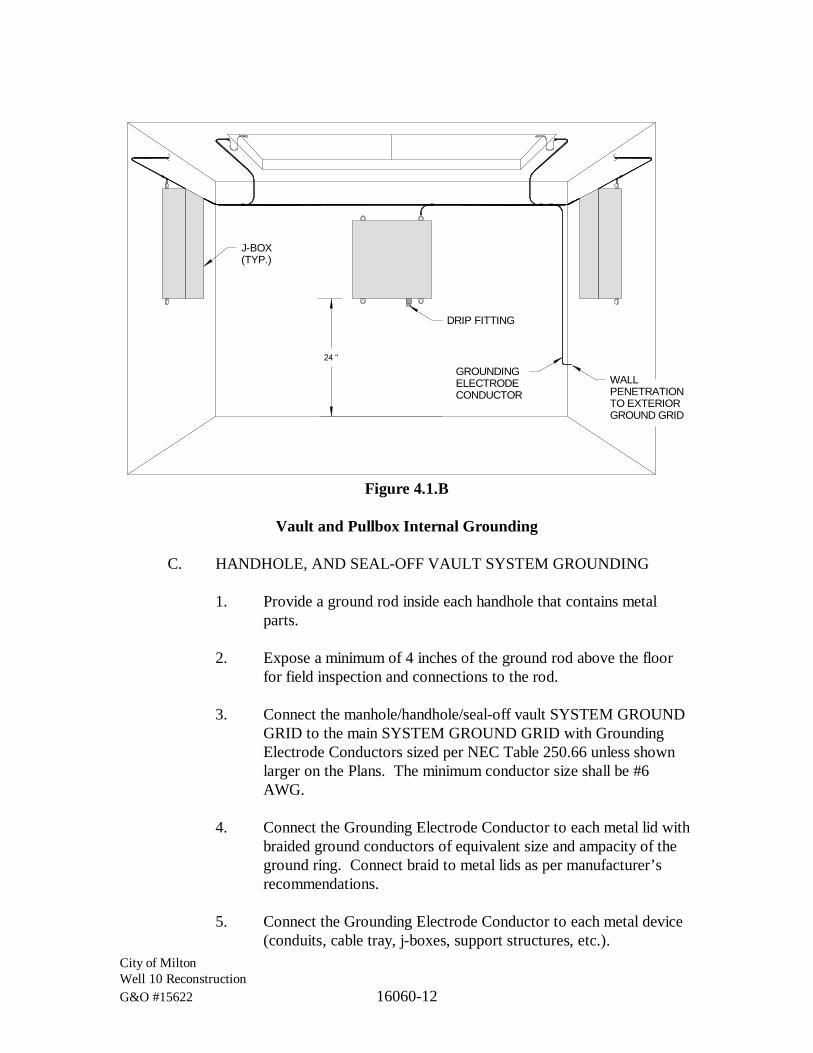
City of MiltonWell 10 ReconstructionG&O #15622 16060-12
J-BOX(TYP.)
24 "
DRIP FITTING
GROUNDINGELECTRODECONDUCTOR
WALLPENETRATIONTO EXTERIORGROUND GRID
Figure 4.1.B
Vault and Pullbox Internal Grounding
C. HANDHOLE, AND SEAL-OFF VAULT SYSTEM GROUNDING
1. Provide a ground rod inside each handhole that contains metalparts.
2. Expose a minimum of 4 inches of the ground rod above the floorfor field inspection and connections to the rod.
3. Connect the manhole/handhole/seal-off vault SYSTEM GROUNDGRID to the main SYSTEM GROUND GRID with GroundingElectrode Conductors sized per NEC Table 250.66 unless shownlarger on the Plans. The minimum conductor size shall be #6AWG.
4. Connect the Grounding Electrode Conductor to each metal lid withbraided ground conductors of equivalent size and ampacity of theground ring. Connect braid to metal lids as per manufacturer’srecommendations.
5. Connect the Grounding Electrode Conductor to each metal device(conduits, cable tray, j-boxes, support structures, etc.).
City of MiltonWell 10 ReconstructionG&O #15622 16060-13
4.2 CONNECTIONS
A. GENERAL
Make connections so possibility of galvanic action or electrolysis isminimized. Select connectors, connection hardware, conductors, andconnection methods so metals in direct contact will be galvanicallycompatible.
1. Use electroplated or hot-tin-coated materials to assure highconductivity and to make contact points closer in order of galvanicseries.
2. Make connections with clean, bare metal at points of contact.
3. Coat and seal connections having dissimilar metals with inertmaterial to prevent future penetration of moisture to the contactsurfaces.
B. EQUIPMENT GROUNDING-WIRE TERMINATIONS
Make the grounding conductor connections to motors or equipment 10 hpand above or 20 amperes and above, with conductor termination and a5/16 of an inch minimum bolt tapped to the motor frame or equipmenthousing. Ground connection to smaller motors and equipment may bemade by fastening the conductor termination to a connection box.
C. METAL RACEWAY TERMINATIONS
Where metallic raceways terminate at metallic or non-metallic enclosures,panels, or housings, terminate each conduit with a grounding bushing.Connect grounding bushings with a bare grounding conductor togrounding bus or terminal in housing. Bond electrically noncontinuousconduits at both entrances and exits with grounding bushings and baregrounding conductors, except as otherwise indicated.
D. CONNECTION TORQUE
Tighten screws and bolts for grounding and bonding connectors andterminals according to manufacturer’s published torque-tightening values.Where these requirements are not available, use those specified in UL486A and UL 486B.
City of MiltonWell 10 ReconstructionG&O #15622 16060-14
E. COMPRESSION-TYPE CONNECTIONS
Use hydraulic compression tools to provide correct circumferentialpressure for compression connectors. Use tools and dies recommended bymanufacturer of connectors. Provide embossing die code or other standardmethod to make a visible indication that a connector has been adequatelycompressed on grounding conductor.
4.3 QUALITY CONTROL
A. INDEPENDENT TESTING AGENCY
Engage an independent electrical testing organization to perform testsdescribed below.
B. TESTS
1. Subject the completed GROUNDING ELECTRODE SYSTEM toa 3-point fail-of-potential ground test according to IEEE 81.Perform the test not less than 2 full days after the last trace ofprecipitation, and without the soil being moistened by any meansother than natural drainage or seepage, and without chemicaltreatment or other artificial means of reducing natural groundresistance.
2. These 3rd party measurements shall be documented, signed, andsubmitted to the Engineer for approval prior to commissioning atthe site.
C. MAXIMUM GROUNDING RESISTANCE VALUES
Maximum grounding resistance values shall be as listed below:
1. Equipment grounding connections: 25 ohms.
2. Main Service (grounding electrode): 5 ohms.
D. EXCESSIVE GROUND RESISTANCE
Where resistance to ground exceeds specified values, notify the Engineer.Check connections of affected equipment and conductors. Replace orrepair defective connections or conductors. Provide additional groundrods where the grounding electrode resistance is greater than specified.Revise and retest until resistance is within specifications.

City of MiltonWell 10 ReconstructionG&O #15622 16060-15
E. REPORT
Prepare test reports, certified by the testing organization, of groundresistance at each test location. Include observations of weather and otherphenomena that may affect test results. Describe measures taken toimprove test results.
*** END OF SECTION ***

City of MiltonWell 10 ReconstructionG&O #15622 16120-1
SECTION 16120
CONDUCTORS AND CABLES
PART 1 GENERAL
1.1 SCOPE
The work specified in this Section includes building wires, cables, and associatedconnectors, splices, and terminations for wiring systems rated 600 V and less.
1.2 RELATED WORKS SPECIFIED ELSEWHERE
Section Item01300 Submittals16050 Basic Electrical Materials and MethodsRCW 19.28.261 Revised Code of Washington, Exemptions from RCW
19.28.161 through RCW 19.28.27116940 Control Panels
1.3 SUBMITTALS
See Section 01300.
Indicate Field Test Reports and interpret their results for compliance withperformance requirements.
1.4 QUALITY ASSURANCE
See Section 16050.
PART 2 PRODUCTS
2.1 BUILDING WIRES AND CABLES
A. STRANDING
1. All power, control, and instrumentation conductors shall bestranded.
Exception:
· Conductors #20 AWG and smaller may be solid.
City of MiltonWell 10 ReconstructionG&O #15622 16120-2
2. All equipment ground conductors shall be stranded.
Exception:
· Conductors #16 AWG and smaller may be solid.
3. All grounding electrode conductors shall be stranded.
Exception:
· Conductors #10 AWG and smaller may be solid.
B. POWER AND CONTROL WIRE
All power and control wire and conductors in raceways shall be rated 600VAC.
1. XHHW, XHHW-2
a. Conductor
Class B, stranded, annealed, uncoated copper. Conductorsshall comply with:
i. UL Standard 44.
ii. ASTM-B3, ASTM-B8, and ASTM-B7B8.
b. Insulation
Cross-Linked Polyethylene (XLP) High Heat WaterResistant. Insulation shall comply with:
i. UL-83 Thermoplastic-Insulated Wires and Cables.
ii. UL-1063 Machine-Tool Wires and Cables.
c. The cable shall meet the following Standards and Agencyapprovals:
i. NEMA WC70/ICEA S-95-658.
ii. ASTM Stranding Class B3, B8, B7B8
iii. Federal Specification A-A-59544

City of MiltonWell 10 ReconstructionG&O #15622 16120-3
2. THHN, THWN, THHN/THWN-2
a. Conductor
Copper, annealed, uncoated. Conductors shall complywith:
i. ASTM-B3, ASTM-B8, and ASTM-B7B8.
b. Insulation
Polyvinyl Chloride (PVC), Nylon jacket. Insulation shallcomply with:
i. UL-83 Thermoplastic-Insulated Wires and Cables.
ii. UL-1063 Machine-Tool Wires and Cables.
c. The cable shall meet the following Standards and Agencyapprovals:
i. NEMA WC70/ICEA S-95-658.
3. MTW (Machine Tool Wiring)
a. Conductor
Copper, annealed, uncoated. Conductors shall complywith:
i. ASTM-B3, ASTM-B8, and ASTM-B7B8.
b. Insulation
Polyvinyl Chloride (PVC). Insulation shall comply with:
i. UL-83 Thermoplastic-Insulated Wires and Cables.
ii. UL-1063 Machine-Tool Wires and Cables.
c. The cable shall meet the following Standards and Agencyapprovals:
i. NEMA WC70/ICEA S-95-658.
City of MiltonWell 10 ReconstructionG&O #15622 16120-4
ii. UL Standard UL 83, UL 1063, UL 758 cUL file:E156879 and E123744
iii. AWM Specification 1316, 1317, 1318, 1319, 1320,1321
iv. ASTM Stranding Class B3, B8, B7B8
v. Federal Specification A-A-59544
vi. CSA 22.2 No. 75, UL E156879 and E123744
C. INSTRUMENTATION, COMMUNICATION, AND NETWORKINGCABLES
All instrumentation, communication, and networking cables andconductors in raceway shall be rated 600 VAC.
1. Analog Instrument Cables
Paired and triad analog instrument cables shall be #18 AWGstranded tinned copper 600 V tray cable, rated for wet applicationsat 75 degrees C in a sunlight resistant PVC jacket. Cables shall beplenum and direct burial rated, and shall be provided withindividual pair/triad isolated 100 percent foil shields withindependent drain wires and an overall isolated shield with drainwire.
These cables shall also be used for totalizing pulse signals fromflow meters.
The following cables shall be used for multiple conductorapplications:
a. 2-Conductor, 1 twisted pair, 100 percent overall shield.Belden #9341 or #1120A or equivalent.
b. 3-Conductor, 1 twisted triad, 100 percent overall shield.Belden #1121A or equivalent.
c. 4-Conductor, 2 twisted pairs, 100 percent individual shieldsplus 100 percent overall shield. Belden #1048A orequivalent.
City of MiltonWell 10 ReconstructionG&O #15622 16120-5
2. Ethernet Copper Cables
Ethernet cables shall be 600 V, bonded pair, shielded.
a. Enhanced Category 6 (6e).
i. 600 V, polypropylene insulation, with inner PVCjacket and Industrial Grade, Sunlight and OilResistant, Black, PVC outer jacket.
ii. 8-Conductor, 4 twisted bonded pairs, #23 AWG,solid bare copper, 100% overall foil shield.
iii. 19.8 dB attenuation per 100 meters at 100 MHz.
iv. Beldon #7953A or equivalent.
D. CONTROL AND POWER CABLE/CORDS
1. Power Cords
a. Type SO, 600 Vac, size #14 or larger.
E. CONTROL AND INSTRUMENTATION CABLE CONNECTORS
1. Open Cable to Enclosure Connectors, Exterior Applications
Open cable to enclosure connectors for exterior applications shallbe 316 stainless steel control receptacle/drop cord connector sets:Panel Receptacle = Turck #P-RKFV series; drop cord set = Turck#P-RSM series. Provide separate pins for each cable shield.
2.2 SPLICES, TAPS AND TERMINAL BLOCKS
Splices are only allowed under the conditions of Section 4.2.E.
A. SPLICES TO POWER CONDUCTORS
1. Splices in Outdoor Areas, Handholes, Vaults, or Direct Buried
a. For inline butt splices, use inline resin splice kits for non-shielded cables, 600 V; 3M Scotchcast 82-A series orequal. UL listed 486D.
City of MiltonWell 10 ReconstructionG&O #15622 16120-6
b. For odd-shaped and odd sized splices, use multi-mold resinsplice kits for non-shielded cables, 600 V; 3M Scotchcast85-14CP or equal. UL listed 486D
2. Motor Lead Connectors
a. Motor terminal connectors shall be insulated multiple tapconnectors rated for 600 Vac; N.S.I. Polaris or equal.
3. Power Terminal Blocks
a. All power terminals shall be 600 Vac, suitable for 75degrees C rated copper conductor.
b. Power terminal blocks may be copper or aluminum andshall have a short circuit current withstand rating followingthe guidelines described in UL 1059 and shall meet orexceed the available bolted fault current at the point ofapplication.
B. SPLICES TO CONTROL CONDUCTORS
1. In Junction Boxes and Handholes
Splices to control conductors in junction boxes and handholes shallbe made with 600 V, UL486D certified, water-proof direct buryconnectors with strain relief, pre-filled with waterproof andcorrosion-proof, non-hardening, silicone dielectric sealant;DRYCONN DBSR Series or equal.
2. Terminal Blocks in Panels
Reference Specification 16940 for terminations in Control Panels.
C. SPLICES TO INSTRUMENTATION CABLES AND CONDUCTORS
1. In Junction Boxes
Strip back the cable outer sheath exposing cable conductors andshield lengths to 1-inch or less. Twist the wires together andsolder. Insert and engage into 600 V, UL486D certified, water-proof connectors, pre-filled with waterproof and corrosion-proof,non-hardening, silicone dielectric sealant; DRYCONN AquaSeries or equal.

City of MiltonWell 10 ReconstructionG&O #15622 16120-7
2. In Handholes
Instrument cables and conductors are always passed through ajunction box inside pull boxes and handholes. Reference “InJunction Boxes” (above) and Specification 16130, Section 4.
3. Terminal Blocks in Panels
Reference Specification 16940 for terminations in Control Panels.
2.3 INSULATING MATERIALS
A. ELECTRICAL INSULATION PUTTY
Scotchfill, or equal.
B. INSULATING ELECTRICAL TAPE
7 Mil/0.18 mm Plasticized PVC, rubber-based adhesive, 200 percentelongation, 26 N/cm tensile strength, 8 kV breakdown voltage, meetingCE, CSA, UL certifications.
C. CONDUCTOR COLOR-MARKING TAPE
7 Mil/0.18 mm Plasticized PVC, rubber-based adhesive, 200 percentelongation, 26 N/cm tensile strength, 8 kV breakdown voltage, meetingCE, CSA, UL certifications, in required color.
D. ELECTRICAL HEAT SHRINK TUBING
Heat shrink tubing shall be dual-wall polyolefin, 3-1 shrink ratio, 600 Vac,-55 to 110 degrees C operating range meeting UL 224 600V, 125 degreesC.
PART 3 APPLICATIONS
3.1 WIRE APPLICATIONS
A. CABLE AND CONDUIT SCHEDULE
The Cable and Conduit Schedule shall be considered absolute. Nochanges to wire sizes, wire count, insulation type, or circuit type shall beallowed without approval from the Engineer.

City of MiltonWell 10 ReconstructionG&O #15622 16120-8
B. WIRES IN RACEWAYS
Wires installed in raceways shall be considered “FIELD” wiring and shallbe installed and terminated by qualified and licensed electrical contractors.
Exceptions:
· Installation and termination may be by the owner under theprovisions of “RCW 19.28.261, Exemptions from RCW 19.28.161through RCW 19.28.271.”
· If the raceway is installed inside a control panel fabricated by acertified UL 508 shop, then these wires may be installed andterminated per the provisions of WIRES IN CONTROL PANELS aslisted below.
1. Power Wire
a. Insulation
All service, feeder, and branch circuit conductors shall beXHHW-2.
Exception:
· Unless both ends of wire are installed in the samecontrol panel.
2. Class 1 and 2 Control Wire
a. Insulation
All control circuits in raceways shall be XHHW-2.
b. Minimum control wire size in conduits and raceways
The minimum control wire size in conduits and racewaysshall be #14 AWG.
C. WIRES IN CONTROL PANELS
Wires in control panels are those wires that are not routed throughraceways external to control panels.

City of MiltonWell 10 ReconstructionG&O #15622 16120-9
1. Control Panel Power and Control Wire
a. Insulation
Power and control conductors in control panels shall beMTW or THHN/THWN-2.
b. Wire minimum size and color:
Circuit Type Wire Size Wire Color120 Vac Power Circuits
120 Vac, Line #14 AWG* Black120 Vac, Neutral #14 AWG White120 Vac, Chassis Ground #12 AWG Green
24 Vdc Power Circuits+24 Vdc Power #14 AWG* Red24 Vdc Common #14 AWG Dark BlueIsolated (Shield) Ground #12 AWG Light Blue
PLC I/O CircuitsPLC Digital Inputs (DI) #18 AWG OrangePLC Digital Outputs (DO) #18 AWG** Wht/Org stripePLC Analog Inputs (DI) #18 AWG Shielded CablePLC Analog Outputs (DO) #18 AWG Shielded Cable
Control/Other Circuits24 Vdc Control Circuits #16 AWG*** Purple120 Vac Control Circuits #16 AWG*** Pink
* Minimum wire sizes for AC and DC power circuits shall be #14 AWG whenprotected by a 10 A or smaller Overcurrent Protective Device (OCPD), #12 AWGor larger for OCPD larger than 10 A. Size in compliance with NEC and UL 508.The AC neutral wire size shall always match the line wire.
** PLC Digital Output circuits may be #18 AWG between the PLC output terminaland the buffer relay coil when fused less than or equal to 5A. Wiring from thebuffer relay output contacts to field terminals shall be #14 AWG minimum.
For retrofitted control panels without buffer relays, provideDigital Output wiring at #14 AWG.
D. CONDUCTORS DIRECT BURIED
Refer to the Plans for specifications regarding directly buried conductorsand cables.

City of MiltonWell 10 ReconstructionG&O #15622 16120-10
E. POWER CORDS
SO power cords shall be allowed in control panels for circuits not greaterthan 120 Vac or 48 Vdc. Such applications require installation by a UL508 shop.
PART 4 EXECUTION
4.1 EXAMINATION
Examine raceways and surfaces receiving wires and cables for compliance withrequirements for installation tolerances and other conditions affectingperformance of wires and cables. Do not proceed with installation untilunsatisfactory conditions have been corrected.
4.2 INSTALLATION
A. GENERAL INSTALLATION METHODS
1. Install wires and cables in raceway system, according tomanufacturer’s written instructions and NECA’s “Standard ofInstallation,” after raceway system is complete.
2. Tighten electrical connectors and terminals according tomanufacturer’s published torque-tightening values. Ifmanufacturer’s torque values are not indicated, use those specifiedin UL 486A and UL 486B.
3. Install cables and conductors neatly in all enclosures. Bend orform wires in neat runs from conduits to terminals. Arrange wiresso that they may be grouped by conduit or function in theenclosure. Install cable ties and straps to support and bundle wiresin enclosures. Arrange wires to allow wire tags and numbers to beeasily read without bending or flexing wiring.
4. Leave 6 inches or more of free conductor at each connected deviceor equipment terminal and 9 inches of free conductor at eachunconnected outlet. Tape free ends of conductors at unconnectedoutlets and coil neatly in outlet box.
5. Install wiring to equipment neutral and grounding blocks on thebottom or furthest back row first. Leave unconnected blocksaccessible for future neutral or grounding connections.

City of MiltonWell 10 ReconstructionG&O #15622 16120-11
6. Provide individual neutral conductors for each associated circuit.Common neutral conductors for multi branch circuits are notpermitted.
7. All power distribution raceways shall contain at least onecontinuous copper grounding conductor with a minimum size asper NEC 250.122. Larger sizes shall be used if identified in theCable and Conduit Schedule on the Plans.
B. CONDUCTORS SHARING RACEWAYS
1. Power conductors shall not be run in the same raceway withcontrol conductors.
Exception:
· Unless specifically shown otherwise in the Cable andConduit Schedule.
2. Power conductors shall not be run in the same conduit or racewaywith instrumentation cables/conductors.
3. Control conductors shall not be run in the same conduit or racewaywith instrumentation cables/conductors.
Exception:
· Unless specifically shown otherwise in the Cable andConduit Schedule.
C. CONDUCTORS IN CONTROL PANELS
1. Control Panel Instrumentation (Signal) Wiring
a. Signal cables between analog input and output fieldterminals and a PLC shall be connected to the fieldterminals as shown in Specification 16940.
b. All cables shields shall be terminated at the field terminalend. Connections to the PLC analog input and outputterminals shall not land the shield.
c. Signal cable conductors and their shields/drains shall not beseparated greater than as described below.

City of MiltonWell 10 ReconstructionG&O #15622 16120-12
2. Control Panel Communication and Networking Wiring
a. All communication and networking cables inside controlpanels shall have their ends made up with terminalconnectors. No cables shall be left open-ended.
b. Cables shall be routed inside Panduit™ or neatly tied toother conductor bundles.
D. INSTRUMENTATION (SIGNAL) CABLES
1. Preparing the Shielded End
BLACK HEAT SHRINK OVER CABLEEND AND OPEN CONDUCTORS
INSTRUMENTATIONCABLE
GREEN HEAT SHRINKOVER DRAIN WIRE
0.25"
0.25"
1.25"
1.25"
a. Neatly trim the end of the cable.
b. Strip back 1.25 inch of the outer jacket taking care not tocut into the conductor insulation.
c. Neatly trim the foil back to the edge of the outer jackettaking care not to damage the drain wire.
d. For signal cables with a braided shield over a foil shield,carefully cut the braid back to the edge of the outer jacket.
e. Provide a green heat shrink tube over the drain wire,leaving 0.25 inch of exposed conductor.
f. Provide a 1.25-inch black heat shrink over the jacket,covering 0.25 inch of the exposed conductors. Thisproperly insulates and protects the ends of the shields andthe outer jacket.
g. Strip the signal conductors exposing 0.25 inch ofconductor.

City of MiltonWell 10 ReconstructionG&O #15622 16120-13
2. Preparing the Unshielded End
BLACK HEAT SHRINK OVER CABLEEND AND OPEN CONDUCTORS
INSTRUMENTATIONCABLE
0.25"
0.25"
1.25"
1.25"
a. Neatly trim the end of the cable.
b. Strip back 1.25 inch of the outer jacket taking care not tocut into the signal conductor insulation.
c. Neatly trim the foil back to the edge of the outer jacket.
d. Cut the drain wire at the edge of the outer jacket taking carenot to damage the signal conductor insulation.
e. For signal cables with a braided shield over a foil shield,carefully cut the braid back to the edge of the outer jacket.
f. Provide a 1.25-inch black heat shrink over the jacket,covering 0.25 inch of the exposed conductors. Thisproperly insulates and protects the ends of the shields andthe outer jacket.
g. Strip the signal conductors exposing 0.25 inch ofconductor.
E. SPLICING CONDUCTORS
1. Install service, feeder, and motor circuits continuous withoutsplices from equipment terminal to equipment terminal or motorlead.
Exceptions:
· Service entry feeders at weatherheads.
· Branch circuits at taps for convenience receptacles andlighting.
· As specifically called out.

City of MiltonWell 10 ReconstructionG&O #15622 16120-14
· With written permission from the Engineer.
2. Install instrumentation and control circuits continuous withoutsplices or terminations from source equipment terminal todestination equipment terminal.
Exceptions:
· On terminal strips in control panels.
· On terminal strips in termination panels.
3. Where splicing is allowed, or specifically called out, install in thefollowing manner:
a. Splicing Inside Vaults, Handholes, Outdoor J-Boxes, or J-Boxes in Wet Areas
Power and control conductors shall be spliced per Section2.2.A. Provide a minimum of 24 inches of length on bothwires for future re-splicing.
b. Splicing Inside Motor J-Boxes
Power connections inside motor j-boxes shall be madeusing insulated multiple tap connectors rated for 600 Vac;N.I.S. Polaris or equal. Cover the splice with a minimumof three layers of black insulating electrical tape. Provide asingle band with a minimum of two wraps of theappropriate phase color tape to the entry T-lead. Bend theconnections away from the sides of the j-box and motorframe to prevent abrasion from motor vibration.
Control connections inside motor j-boxes shall be madewith crimped butt-splices with heat shrink covers. The heatshrink shall overlap the butt barrel ends by a minimum of1/2 inch on each side. Cover the splice with a minimum ofthree layers of black insulating electrical tape.
F. REPLACING FAULTY CONDUCTORS
When replacing a faulty conductor or cable that shares a raceway withother conductors or cables, all conductors and cables must be removed andreplaced with new.

City of MiltonWell 10 ReconstructionG&O #15622 16120-15
Exceptions:
· If the raceway is straight and without bends or offsets and itslength is less than 30 feet, and the conductors are not boundtogether in the raceway, then only the faulty cable must be pulledand replaced with new. A manufacturer-approved pullingcompound or lubricant must be used to minimize degradation tothe remaining conductors. The contractor is responsible for theintegrity of the remaining conductors.
· With specific approval by the Engineer.
G. CONDUCTOR LABELLING
All conductors shall be labeled in the following manner.
Exceptions:
· Conductors supplying power to lighting and conveniencereceptacles.
· Non-insulated ground conductors.
· At each motor tag for winding lead numbers. Make all phaserotation changes for motor direction changes at the motor tomaintain correct color phase sequence in equipment.
· In each enclosure or box where more than one ungrounded powerconductor is spliced or connected, tag for panelboardidentification and pole number (reference Section 3.3C.).
1. Conductors shall be labeled the same at each end in a place wherethe label can be clearly read without moving other wires or rotatingthe label.
2. Conductor labels shall reference the device (destination) tag asprovided on the “TAG LIST” in the Plans. For example,conductors from panelboard [01 PB 01] to dedicated receptacle[01 DREC 05] shall be labeled as follows:
Line: 01DREC05.LNeutral: 01DREC05.NGround: 01DREC05.G
City of MiltonWell 10 ReconstructionG&O #15622 16120-16
3. Conductor labels shall each be unique for each circuit. Forexample, 10 control conductors from Main Control Panel[02 CP 01] (source) to Automatic Transfer Switch [02 ATS 01](destination) shall be labeled as follows:
Wire #1: 02ATS01.01Wire #2: 02ATS01.02 | |Wire #9: 02ATS01.09Wire #10: 02ATS01.10
4. The labels shall be white heat shrink sized appropriately for theassociated conductor with typed lettering in black indelible ink.
5. Label each conductor. When terminating cables, if there isinsufficient room to provide a label on each conductor, then labelthe cable sheath.
6. Tag for phase rotation at each power connection.
Exception:
· At motor connections.
H. CONDUCTOR COLORS
1. For conductor colors inside control panels, referenceSection 3.1.C.1.
2. Do not use white, gray, green, or green with yellow stripes colorfor any power, lighting, or control conductor not intended forneutral or equipment grounding purposes.
Exception:
· Instrumentation and control multi-conductor cables mayuse white, gray, or green singly or as part of a trace colorin addition to the base color.
3. Equipment grounding conductors: Green or green with yellowstripes.

City of MiltonWell 10 ReconstructionG&O #15622 16120-17
4. 480/277 volt, 3-phase systems:
Phase A Phase B Phase C NeutralBrown Orange Yellow Gray
5. 208/120 or 240/120 volt, 3-phase systems:
Phase A Phase B Phase C NeutralBlack Red Blue White
6. 240/120 volt, single phase systems:
Phase A Phase B NeutralBlack Red White
7. Use wire with insulation of required color for conductors of #6AWG and smaller. For wire larger than #6 AWG, where notavailable in specified colors, use conductor color marking tape perSection 2.3.C. When conductors are marked in this manner, markeach conductor at all accessible locations such as panelboards,junction boxes, pullboxes, auxiliary gutters, outlets, switches, andcontrol centers.
8. Connect power conductors of the same color to the same phasethroughout the installation. Viewing all equipment from the front,make connections so phase color sequence is in the same order asthat for panelboards, switchboards, motor control centers, etc.
I. PULLING CONDUCTORS
1. Instrumentation, Communication, and Networking Cables
Make all cable pulls by hand using a manufacturer-approvedpulling compound or lubricant where necessary.
2. Power and Control Conductors
a. Make all cable pulls by hand where possible. Use pullingmeans, including fish tape, cable, rope, and basket-weavewire/cable grips, or wrapping extra conductor into an eye,that will not damage cables or raceway.
b. On mechanically-assisted pulls use a manufacturer-approved pulling compound or lubricant where necessary.The compound used must not deteriorate the conductors or

City of MiltonWell 10 ReconstructionG&O #15622 16120-18
insulation. Do not exceed manufacturer’s recommendedmaximum pulling tensions and sidewall pressure values.Install pullboxes where necessary to prevent exceedingmanufacturer’s recommendations.
3. Cut cable or conductor ends off after pulling and clean all pullingcompound from exposed conductors before terminating.
J. CABLE SUPPORTS
Support cables according to Section 16050.
Provide vertical conductor support per NEC Table 300.19(A).
K. WIRING AT OUTLETS
1. Install conductor at each outlet, with at least 6 inches of slack.Connect only to receptacle screw terminals using insulated spade-type lugs.
2. Connect outlets and components to wiring and to ground asindicated and instructed by manufacturer, and in compliance withother Sections of Division 16.
4.3 FIELD QUALITY CONTROL
A. TESTING
On installation of wires and cables and before electrical circuitry has beenenergized, demonstrate product capability and compliance withrequirements.
1. Procedures
Perform each visual and mechanical inspection and electrical teststated in NETA ATS, Section 7.3.2. Certify compliance with testparameters.
2. Remove and replace conductors with visible insulation damage onconductor ends due to installation in an incomplete or damagedconduit system such as, but not limited to, missing bushings orburrs on conduit ends.

City of MiltonWell 10 ReconstructionG&O #15622 16120-19
3. On THWN, THHN, THHW conductors, a tear, rip, or blister in theouter insulation sheath shall be considered damaged insulation andshall be replaced as described in Section 4.3.A.2.
B. POWER CONDUCTOR TESTING
After pulling and prior to connection, perform a Megger test between allconductors (including the equipment ground) and between each conductorand earth ground in the following manner:
1. Perform megger tests at 600 V.
2. Record ambient temperature and humidity during testing.
3. Cables or conductors with a steady-state value less than100 megohms shall be considered “failed”.
4. Complete a Power Conductor Megger Testing Report and submitas per Section 16050.
C. CONTROL AND INSTRUMENTATION CONDUCTOR TESTING
Control and instrumentation circuits shall not be meggered.
1. Perform insulation tests with a Digital Voltmeter.
2. Record ambient temperature and humidity during testing.
3. Cables or conductors with a steady-state value less than100 megohms shall be considered “failed”.
D. CORRECTIVE ACTION FOR FAILED CABLES AND CONDUCTORS
Failed cables and conductors shall be removed and replaced with new andretested per Section 4.2.D.
*** END OF SECTION ***

City of MiltonWell 10 ReconstructionG&O #15622 16130-1
SECTION 16130
RACEWAY AND BOXES
PART 1 GENERAL
1.1 SCOPE
The work specified in this Section includes raceways, fittings, boxes, enclosures,and cabinets for electrical wiring.
1.2 RELATED SECTIONS INCLUDE THE FOLLOWING:
Sections Items01300 Submittals02530 Utility Structures16050 Basic Electrical Materials and Methods16060 Grounding and Bonding16120 Conductors and Cables16140 Wiring Devices
1.3 DEFINITIONS
A. 100 PERCENT CONTINUOUS
100 percent continuous means that electrical continuity shall be maintainedover a conduit’s entire length and that such conduits shall consist of onlyRGS (whether PVC-coated or not), LFMC, or combinations of thesetypes. There can be no break in the electrical continuity by non-metalliccomponents.
EMT conduits are not considered 100 percent continuous.
B. CONDUIT BODIES
A separate portion of a conduit system that provides access through aremovable cover to the interior of the system at a junction of two or moresections of the system.
C. CONTROL CONDUITS
Control conduits typically contain cables or conductors in the range of12 Vdc to 120 Vac. These cables/conductors are used to provide discreetfield inputs and outputs to motor drives, PLC controllers, operator
City of MiltonWell 10 ReconstructionG&O #15622 16130-2
stations, etc. They typically connect to discreet I/O field devices like localpanel pushbuttons, indicating lights, selector switches, field limit switches,relay circuits, etc.
D. CONTROL PANELS
Control panels are enclosures in which one or more circuits are changed,unlike junction boxes where circuits are simply routed through the panel.Control panels may be as simple as an enclosure with a pilot light or theymay be very complicated with hundreds of I/O terminations. For ControlPanel considerations, reference Specification 16940.
E. CONVENIENCE RECEPTACLES
Reference Section 16140, Definitions.
F. DEVICE BOXES
Device boxes are electrical boxes used for receptacles, light switches,dimmers, and other similar devices. Selector switches, indicating lights,displays, etc., are mounted in control panels and equipment enclosures, notin device boxes.
G. DRIP FITTINGS
Drip fittings are used to drain water from conduit entry points, junctionboxes, or other enclosures where accumulation of moisture must beremoved. They are also intended to disable the entry of foreign materials,including tools and fingers, through the drain.
H. EMT
Electrical Metallic Tubing (a type of RMC).
I. EQUIPMENT VAULT
An Equipment Vault is a VAULT that contains one or more electricaldevices that are terminated within the vault; such as flow meters, controlvalves, control or power panels, lighting, and etc.
SEE VAULTS
City of MiltonWell 10 ReconstructionG&O #15622 16130-3
J. HANDHOLES
A handhole is a pullbox that is not sufficiently sized for entrance ofpersonnel (reference PULLBOXES).
K. INSTRUMENTATION CONDUITS
Instrumentation conduits contain cables and conductors that carrylow-power modulated or communication signals. They may include4-20 mA current loops, 0–10 volt analog signals, 5 to 12 Vdc digital (TLL)data, analog or digital communications signals, etc. They may also includelow-voltage compliance power to instruments such as 5 Vdc, ±15 Vdc, or24 Vdc.
L. INTRINSICALLY SAFE CIRCUIT
A circuit in which any spark or thermal effect, produced either normally orin specified fault conditions, is incapable of releasing sufficient electrical orthermal energy to cause ignition of a specific hazardous atmosphericmixture in its most easily ignitable concentration.
M. JUNCTION BOXES
Junction boxes are electrical enclosures used for combining, splitting,pulling, or redirecting electrical circuits. Junction boxes may terminate oneconduit or join multiple conduits. Circuits are not altered inside a junctionbox. Enclosures where circuits are altered are called CONTROLPANELS. With the exception of terminal strips, junction boxes do notcontain electrical devices.
1. Junction Boxes, Type J1
Junction boxes identified as TYPE J1 can contain only non-linearpower circuits.
2. Junction Boxes, Type J2
Junction boxes identified as TYPE J2 can contain only intrinsicallysafe circuits.
3. Junction Boxes, Type J3
Junction boxes identified as TYPE J3 can contain onlyinstrumentation circuits that are not intrinsically safe.

City of MiltonWell 10 ReconstructionG&O #15622 16130-4
Junction boxes not containing circuits of the types identified for TYPE J1,TYPE J2, or TYPE J3 are simply called “junction boxes” (without a TYPEidentifier).
N. LFMC
Liquidtight Flexible Metal Conduit (a type of RMC).
O. LINEAR POWER LOADS
Linear power loads are those that are not VFD circuits (both line or load),and are not UV ballast circuits. Although actually non-linear, fluorescentlighting circuits shall be considered linear power loads.
P. NON-LINEAR POWER LOADS
Non-linear power loads shall include all VFD circuits (both line or load)and all UV ballast circuits. Although actually non-linear, fluorescentlighting circuits shall be considered linear.
Q. POWER CONDUITS
Power conduits contain branch and feeder conductors with voltages120 Vac and above. These conductors provide operating power to MCCs,panels, motors, lighting, receptacles, HVAC, etc. Conductors can be of#12 AWG wire gauge and larger, either separate or in power cables.
R. PROCESS AREAS
Reference Section 16050, Definitions.
S. PULLBOXES
Pullboxes are underground electrical enclosures, sufficiently sized to allowthe entrance of personnel, used for combining, splitting, pulling, orredirecting electrical circuits. Pullboxes may terminate one conduit or joinmultiple conduits. A pullbox can be considered an underground junctionbox.
Circuits are not altered or terminated inside a pullbox. Pullboxes do notcontain electrical equipment or devices.

City of MiltonWell 10 ReconstructionG&O #15622 16130-5
Exception:
· Pull boxes may include a sump pump.
Handholes are types of pull boxes but are not sufficiently sized to allow theentrance of personnel (reference HANDHOLES).
T. PVC
Polyvinyl Chloride Conduit (a type of RNC).
U. PVC-RGS
Polyvinyl chloride, externally coated RGS (a type of RMC).
Alias: May be called or shown on Plans and elsewhere in specifications asPVC-Coated RGS or PVC-RMC.
V. RGS
Rigid Galvanized Steel (a type of RMC).
W. VAULTS
A vault is an underground structure, serviceable or accessible only from thetop. Handholes, Equipment Vaults, and Pullboxes are considered vaults.
X. WET LOCATIONS
Reference Section 16050, Definitions.
Y. WIREWAYS
Sheet metal troughs with hinged or removable covers for housing andprotecting electric wires and cable in which conductors are laid in placeafter the wireway has been installed as a complete system.
1.4 SUBMITTALS
A. Submit under provisions of Section 01300.
B. Provide data for surface raceways, wireways and fittings, hinged-coverenclosures, and cabinets.
City of MiltonWell 10 ReconstructionG&O #15622 16130-6
1.5 QUALITY ASSURANCE
See Section 16050.
1.6 COORDINATION
Coordinate layout and installation of raceways and boxes with other constructionelements to ensure adequate headroom, working clearance, and access.
Coordinate electrical work with outside utilities associated with the project.
Non electrical piping and structural has priority over underground conduit routing.
Exception:
· Unless specifically coordinated otherwise with the General Contractor.
PART 2 PRODUCTS
2.1 METALLIC CONDUIT TYPES
A. LFMC
1. Conduit
Flexible, galvanized steel convolutions forming a continuousraceway, covered by a liquid tight PVC layer. Electri-Flex TypeLA or American Sealtite, Type UA
2. Connectors
Galvanized steel, screw in, grounding type with a ferrule, whichcovers the end of the inside and outside of the conduit.
B. RGS
1. Conduit
Hot dipped galvanized with threaded ends meeting ANSI C80.1.
City of MiltonWell 10 ReconstructionG&O #15622 16130-7
2. Couplings
Steel, cast iron, or malleable iron compression type employing asplit, corrugated ring and tightening nut, with integral bushings andlocknuts. No indent or set screw type.
a. Couplings
Unsplit, NPT threaded steel cylinders with galvanizing equalto the conduit.
b. Nipples
Factory made through 8 inches, no running threads.
c. Conduit bodies shall be galvanized, or epoxy coated castiron or aluminum one piece with galvanized, or epoxycoated cast cover, gasket, and threaded hubs. Use stainlesssteel screws or other approved non-corroding screws tohold cover in place.
3. Conduit Clamps
Conduit clamps for RGS shall be cast iron.
C. PVC-COATED RGS, PVC-RMC
1. General
a. A proprietary colored urethane coating shall be uniformlyand consistently applied to the interior of all conduit andfittings. This internal coating shall be a nominal 2 milthickness. Conduit or fittings having areas with thin or nocoating shall be unacceptable.
b. The PVC exterior and urethane interior coatings applied tothe conduit shall afford sufficient flexibility to permit fieldbending without cracking or flaking at temperatures above30 degrees F (-1 degrees C).
c. All male and female threads on conduit, elbows, and nipplesshall be protected by application of an electronicallyconducting corrosion resistant compound.

City of MiltonWell 10 ReconstructionG&O #15622 16130-8
d. Installation of the PVC coated conduit system shall beperformed in accordance with the manufacturer’sinstallation manual.
e. Conduits and fittings shall meet the following standards:
i. ASTM D870
ii. ASTM D1151
iii. ASTM D3359
iv. ASTM D1308
v. NEMA RN1
2. Conduit
a. The PVC coated rigid metal conduit must be UL listed. ThePVC coating must have been investigated by UL asproviding the primary corrosion protection for the rigidmetal conduit. Ferrous fittings for general service locationsmust be UL listed with PVC as the primary corrosionprotection. Hazardous location fittings, prior to plasticcoating must be UL listed. All conduit and fittings must benew, unused material. Applicable UL standards mayinclude: UL 6 Standard for Safety, Rigid Metal Conduit,UL 514B Standard for Safety, Fittings for Conduit andOutlet Boxes.
b. The conduit shall be hot dip galvanized inside and out withhot dipped galvanized threads.
3. Fittings and Accessories
The design shall be equipped with a positive placement feature toease and assure proper installation. Certified results confirming sealperformance at 15 psig (positive) and 25 inches of mercury(vacuum for 72 hours shall be available).
a. A PVC sleeve extending one pipe diameter or 2 inches,whichever is less, shall be formed at every female fittingopening except unions. The inside sleeve diameter shall bematched to the outside diameter of the conduit.

City of MiltonWell 10 ReconstructionG&O #15622 16130-9
b. The PVC coating on the outside of conduit couplings shallhave a series of longitudinal ribs 40 mils in thickness toprotect the coating from tool damage during installation.
c. Conduit Form 8 Bodies shall be 1/2 inch through 2-inchdiameter, shall have a tongue-in-groove “V-Seal” gasket toeffectively seal against the elements. Conduit bodies shallbe Form 8 and shall be supplied with plastic encapsulatedstainless steel cover screws.
d. Right angle beam clamps and U bolts shall be speciallyformed and sized to snugly fit the outside diameter of thecoated conduit. Al U bolts will be supplied with plasticencapsulated nuts that cover the exposed portions of thethreads.
e. Conduit clamps and fittings for PVC-Coated RGS conduitsshall be 316L stainless steel.
4. Approved Material
a. Plasti-Bond REDH2OT, Perma-Cote, or KorKapmanufactured by Robroy Industries.
b. Ocal-Blue Steel conduit and fittings as manufactured byOcal, Inc.
c. Any deviation from the above approved materials must beapproved by the Engineer.
2.2 NONMETALLIC CONDUIT TYPES
A. PVC
1. Conduits
NEMA TC 2, Schedule 40 or 80 PVC.
2. Fittings and Accessories
NEMA TC 3; match to conduit type and material, but elbows shallbe RMC.

City of MiltonWell 10 ReconstructionG&O #15622 16130-10
3. Conduit bodies
Where allowed, shall match type, material, and gauge of conduit.
2.3 OTHER RACEWAYS
A. METALLIC WIREWAYS
1. Material
Sheet metal, sized and shaped as indicated.
2. Fittings and Accessories
Include couplings, offsets, elbows, expansion joints, adapters, hold-down straps, end caps, and other fittings to match and mate withwireways as required for complete system.
3. Wireway Covers
a. Hinged type
b. Screw-cover type
c. Flanged-and-gasketed type
4. Finish
Manufacturer’s standard enamel finish.
2.4 OUTLET AND DEVICE BOXES
A. STANDARD METAL BOXES
Assembled from stamped steel hot dipped zinc galvanized coated flatpieces, welded or mechanical assembled into a device box, with knockoutsfor conduit or connector entrance, meeting NEMA OS 1, with plaster orextension rings and necessary mounting appurtenances to suiteconstruction and application.

City of MiltonWell 10 ReconstructionG&O #15622 16130-11
B. CAST BOXES
1. Cast Aluminum
Epoxy coated cast aluminum box, one piece, with mounting lugs,with threaded holes or hubs, with internal green ground screw andwith neoprene gaskets.
2. Cast Iron
Cast iron with electro-galvanized and aluminum acrylic paint finish,one piece, with mounting lugs, with threaded holes or hubs, withinternal green ground screw and with neoprene gaskets.
C. DEVICE COVERS
1. Aluminum: Sheet Aluminum.
2. Cast Iron: Iron alloy.
D. SWITCH ACTUATORS
1. Aluminum: Lever-arm type, raintight, cast aluminum matching themetallurgy of the device box.
2. Cast Iron: Lever-arm type, raintight, cast iron alloy matching themetallurgy of the device box.
E. WEATHERPROOF COVERS AND PLATES
Weather proof, self-closing, die-cast aluminum, UL listed.
F. IN-SERVICE COVERS
Shall be weather proof and hinged from top with removable cord slots.
2.5 JUNCTION BOXES, HANDHOLES, AND VAULTS
A. JUNCTION BOXES
1. Stainless Steel
NEMA 4X 316L stainless steel with gasketed screw down cover.

City of MiltonWell 10 ReconstructionG&O #15622 16130-12
B. HANDHOLES
1. Material and Strength
Handholes shall be made from Concrete or Polymer Concrete. Theboxes and covers are required to conform to all test provisions ofANSI/SCTE 77 2002 “Specification For Underground EnclosureIntegrity” for Tier 15 applications (Design Load Vertical 22,500lbs. and Lateral 800 lbs/sq. ft.) and to be Listed and Labeled. Theboxes must physically accommodate and structurally supportcompatible covers, which possess the Tier rating. In no assemblycan the cover design load exceed the design load of the box. Allcomponents in an assembly (box and cover) are to be manufacturedby the same manufacturer. All covers are required to have aminimum coefficient of friction of 0.50 in accordance with ASTMC1028. Independent third party verification or test reports stampedby a registered Professional Engineer certifying that all testprovisions of this specification have been met are required witheach submittal. The cover is to have an identifying functiondescriptor imprinted on it. The Descriptor shall be ELECTRICAL,CONTROL, SIGNAL, TELEPHONE, STREET LIGHT, or similarapproved by the Engineer.
Handholes with metallic lids shall be grounded per SpecificationSection 16060.
Handhole lid assemblies comprised of steel shall have a factory-applied galvanized finish.
Exception:
· Unless the assembly is fabricated from stainless steel.
2. Manufacturers
Quazite (Strongwell Corp.)Carson Industries
C. VAULTS
Precast concrete structures with preformed knockout holes for conduitentrance. Reference Section 02530, Utility Structures.
Vaults with metallic lids shall be grounded per Specification Section 16060.

City of MiltonWell 10 ReconstructionG&O #15622 16130-13
Exception:
· Unless the assembly is fabricated from stainless steel.
PART 3 APPLICATION
3.1 CONDUIT BODIES
This section describes the types of raceways, junction boxes, and device boxes thatcan used for different circuits and different environments. Reference Section 4.1for methods and practices required for installation.
A. CABLE AND CONDUIT SCHEDULE
The Cable and Conduit Schedule shall be considered absolute. No changesto wire sizes, wire count, insulation type, circuit type, or conduit size shallbe allowed without approval from the engineer.
The Cable and Conduit Schedule does not indicate conduit type (PVC,EMT, RGS, etc.) since, in many cases, a conduit’s type may changebetween its source and destination. The rules stated in this specificationdefine the necessary and allowed conduit type(s) for various applicationsand routes.
B. RACEWAY REQUIREMENTS
The term “RGS conduits” refers to a type of conduit body and does notimply whether the conduit is PVC-coated or not. Certain applicationsrequire RGS conduits with PVC coating, others do not. Reference Section3.2, “RGS RACEWAY PROTECTIVE COATINGS” for theserequirements.
1. Circuit Types and Categories
a. Circuit Types
Conduits are broken into three general circuit types; 1)Power, 2) Control, and 3) Instrumentation (see Definitions).
On the Cable and Conduit Schedule, Power conduits arethose starting with the letter "P", Control conduits are thosestarting with the letter "C", and Instrumentation conduitsare those starting with the letter "S".

City of MiltonWell 10 ReconstructionG&O #15622 16130-14
b. Circuit Categories
Power circuits are broken into two categories, those thatcontain linear loads and those that contain non-linear loads(see Definitions).
Control and Instrumentation circuits are broken into twocategories, those that contain intrinsically safe circuits andthose that do not (see Definitions).
These types and categories are listed below in Table 3.1.B.1below.
c. Relationships Between Circuit Categories and ConduitTypes
Many electrical circuit types do not require special conduitrouting considerations. However, Table 3.1.B.1 showsthree (3) circuit types where the conduit route must be100 PERCENT CONTINUOUS (reference Definitions).
Table 3.1.B.1
Circuit
Type Category100%
Continuous?Power Linear NoPower Non-linear YesControl Non-intrinsic NoControl Intrinsic YesInstrumentation Non-intrinsic YesInstrumentation Intrinsic Yes
2. Conduit Shape
Wiring shall be routed in pipe or tubular conduits, NOT infabricated wireways or gutters.
Exception:
· Unless specifically called out otherwise in the Plans.

City of MiltonWell 10 ReconstructionG&O #15622 16130-15
C. PVC SCHEDULE 40 RACEWAY APPLICATIONS
1. All straight portions of conduits completely concealed in walls,attics, concrete, or below ground (not exposed) shall be PVCSchedule 40.
Exceptions:
· Power conduits containing non-linear loads shall be100 percent continuous over their entire length.
· Control conduits containing intrinsically safe circuits shallbe 100 percent continuous over their entire length.
· All Instrumentation conduits shall be 100 percentcontinuous over their entire length.
· All conduits containing grounding electrode conductorsshall be PVC Schedule 80 over their entire length.
· PVC conduit areas under roads or heavy traffic areas shallbe Schedule 80.
· Where specifically called out otherwise in the Cable andConduit Schedule.
D. PVC SCHEDULE 80 RACEWAY APPLICATIONS
1. All portions of conduits which contain grounding electrodeconductors shall be PVC Schedule 80 and shall contain no metalfittings, connectors, or devices. Such conduits containinggrounding electrode conductors shall contain no other types ofconductors.
2. PVC conduit areas under roads or heavy traffic areas.
3. As stated in the Cable and Conduit Schedule.
E. RGS RACEWAY APPLICATIONS
1. All conduits requiring 100 percent continuity per Section 3.1.B.1shall be RGS over their entire length. For coating requirements,reference Section 3.2.

City of MiltonWell 10 ReconstructionG&O #15622 16130-16
Exception:
· LFMC conduit shall be allowed per the “LFMC RacewayApplications” section herein.
2. Underground factory or bent elbows and offsets greater than orequal to 30 degrees shall be RGS.
Exceptions:
· Where the radius of a conduit bend is greater than or equalto 15 feet per inch of trade size.
· Raceways used for the containment and protection of baregrounding electrode conductors shall be PVC Schedule 80.Reference PVC Schedule 80 raceway applications.
3. All portions of conduits exposed outdoors shall be RGS.
Exception:
· All conduits containing grounding electrode conductorsshall be PVC Schedule 80 over their entire length.
4. All portions of conduits under covered structures open on any sideshall be RGS.
Exception:
· All conduits containing grounding electrode conductorsshall be PVC Schedule 80 over their entire length.
· LFMC conduit shall be allowed per the “LFMC RacewayApplications” section herein.
5. All portions of conduits exposed on the inside of below-groundpullboxes, equipment vaults, wet wells, and dry wells (vaults) shallbe RGS.

City of MiltonWell 10 ReconstructionG&O #15622 16130-17
Exceptions:
· All conduits immediately terminating after penetrating avault wall, that are allowed to be PVC Schedule 40underground, shall terminate as a PVC conduit bell-end.
If the conduit is connected inside the vault to any device,conduit body, junction box, control panel, or any otherconduit, then all portions of the conduit inside the vault,through the wall penetration, and 24 inches outside thevault shall be RGS and shall be grounded.
· All conduits containing grounding electrode conductorsshall be PVC Schedule 80 over their entire length.
6. All portions of conduits penetrating concrete floors, walls, orceilings shall be RGS.
Exception:
· In below ground vaults as described above.
7. All conduit penetrations from grade shall be RGS.
Exception:
· All conduits containing grounding electrode conductorsshall be PVC Schedule 80 over their entire length.
8. All portions of exposed conduits inside closed buildings shall beRGS.
Exceptions:
· LFMC conduit shall be allowed per the “LFMC RacewayApplications” section herein.
· All conduits containing grounding electrode conductorsshall be PVC Schedule 80 over their entire length.
· Unless otherwise specifically called out on a separate planor detail.

City of MiltonWell 10 ReconstructionG&O #15622 16130-18
F. LFMC RACEWAY APPLICATIONS (REFERENCE DEFINITIONS)
1. LFMC conduit shall be used for the last 18 inches of connection tomotors, transformers and other vibrating equipment.
2. LFMC conduit shall be used for the last 18 inches of connection tofield instruments such as flow meters in vaults and ultrasonic leveltransducers.
3. LFMC conduit shall be used for the last 18 inches of connection toany device that may require minor movement during maintenanceor repair or that may require physical adjustment.
4. LFMC conduit shall be used for connections between fixed rigidconduits at the swivel point of headworks screens and other similartypes of applications per Figure 3.1.F.3. Provide a complete loopof LMFC conduit of sufficient length to allow complete andunencumbered motion of equipment.
SWIVEL POINT
ROTATING ARM
PVC-COATEDRIGID CONDUIT
LFMC
FIXED STRUCTURE
CAST J-BOX
MOTION
SEAL-OFF
PVC-COATEDRGS CONDUIT
Figure 3.1.F.3
Example of LFMC Application at a Swivel Point

City of MiltonWell 10 ReconstructionG&O #15622 16130-19
5. LFMC conduit may be used in pull vaults for connections betweenconduit penetrations and junction boxes inside the vault wherespace is limited.
3.2 RGS RACEWAY PROTECTIVE COATINGS
Protected RGS conduits are used to minimize conduit degradation from moistureand chemicals.
Where called in the Plans or Specifications as “Protected RGS,” “PVC-CoatedRGS,” “PVC-Coated,” “PVC-RGS,” or “PVC-RMC,” all such conduits, elbows,and fittings shall be factory coated PVC as defined in Section 2.1.
A. PVC-COATED RGS CONDUIT APPLICATIONS
1. All portions of RGS elbows, bends, straight pipes, couplings, andfittings buried underground shall be PVC-Coated.
2. All portions of RGS elbows, bends, straight pipes, couplings, andfittings encased in concrete shall be PVC-Coated.
3. All portions of RGS elbows, bends, straight pipes, couplings, andfittings exposed outdoors shall be PVC-Coated.
4. All portions of RGS elbows, bends, straight pipes, couplings, andfittings inside underground vaults, pullboxes, wet wells, and drywells shall be PVC-Coated.
5. All portions of RGS elbows, bends, straight pipes, couplings, andfittings exposed in Chemical Rooms (reference Definitions) shall bePVC-Coated.
6. All portions of RGS conduits penetrating concrete floors andbelow-ground walls and ceilings shall be PVC-Coated at least 12"into the exposed area and extending at least 24" underground.
Exceptions:
· Where specifically noted to be otherwise in the Plans.
· Non-metallic conduits that terminate at the wall of apullbox.
City of MiltonWell 10 ReconstructionG&O #15622 16130-20
3.3 JUNCTION AND DEVICE BOX APPLICATIONS
A. JUNCTION BOXES
1. Junction boxes for Instrumentation, Intrinsically Safe, and Non-Linear Power circuits (see Definitions) shall be hinged steel, 6" x 6"x 4" minimum.
2. Wet Areas (see Definitions).
a. NEMA 4X 316L stainless steel.
Exceptions:
· Except in pullboxes, cast junction boxes shall beallowed for applications where three conduits orless approach from three different directions and noterminations are made inside the junction box.
B. DEVICE BOXES, ACTUATORS, AND COVERS
All exposed boxes shall be of cast construction.
All aluminum and cast iron covers shall be provided with a weatherproofgasket.
1. Outdoors, In Equipment Vaults
a. Receptacles
Cast iron device box body with cast aluminum gasketedcover and top-opening “in-service” cover.
Exception:
· Cast aluminum device box bodies may be used ifspecifically called out on the Plans or approved bythe Engineer.
b. Light Switches
Cast iron device box body with cast iron gasketed cover andlever-arm actuator.

City of MiltonWell 10 ReconstructionG&O #15622 16130-21
Exception:
· Cast aluminum device box bodies with gasketed diecast aluminum covers and lever arm actuators maybe used if specifically called out on the Plans orapproved by the Engineer.
3.4 HANDHOLE APPLICATIONS
A. HANDHOLES
Handholes are used as pull and splice points in underground installationsand are typically installed in driveways, parking lots, and off-roadwayapplications subject to occasional non-deliberate heavy vehicular traffic.
1. Handholes shall be set adjacent to each pole light pedestal.
Exception:
· Unless specifically shown or called out otherwise on thePlans.
PART 4 EXECUTION
4.1 EXAMINATION
Examine surfaces and spaces to receive raceways, boxes, for compliance withinstallation tolerances and other conditions affecting performance of racewayinstallation. Do not proceed with installation until unsatisfactory conditions havebeen corrected.
4.2 INSTALLATION, GENERAL
A. COORDINATION WITH OTHER WORK
Wherever practical, route conduit with adjacent ductwork or piping.
1. Keep raceways at least 6 inches away from parallel runs of flues andsteam or hot-water pipes or other heat sources operating attemperatures above 100 degrees F.
2. When installing utility conduits, comply with the spacing and depthrequirements of the utilities.
City of MiltonWell 10 ReconstructionG&O #15622 16130-22
3. Non-electrical buried piping has routing priority over electricalburials.
B. MOUNTING PRACTICES
1. All conduits in process areas shall be surface mounted unlessspecifically called out otherwise on the Plans.
2. Install raceways, boxes, enclosures, and cabinets as indicated,according to manufacturer’s written instructions.
3. Where several conduits follow a common route, stagger pull boxes,junction boxes, pulling sleeves, and fittings.
C. DEVICE BOX INSTALLATION
1. Coordinate box locations with building surfaces and finishes toavoid bridging wainscots, joints, finish changes, etc.
2. Surface mount boxes to building structures with a minimum of1/4-inch spacing and with a minimum of two fasteners. Provideattachments to withstand an additional force of 100 pounds appliedvertically or horizontally.
3. Set surface-mounted receptacle and lighting boxes in wet areas42 inches above the finished floor to the center of the box, unlesscalled out otherwise in the Plan Set.
4. Set surface-mounted boxes for lighting switches within 12 inches ofthe door opening on the strike or lock side of the door or on theside closing last unless indicated otherwise in the Plan Set.
5. Arrange boxes used in wet areas to drain moisture away fromdevices or enclosures for equipment and make conduit connectionsfrom below.
6. Set floor boxes level and adjust to finished floor surface.
D. CONDUIT INSTALLATION
Install conduit as a complete and continuous system without wires.Mechanically secure to boxes, fittings, and equipment. Electrically connectconduits to all metal boxes, fittings, and equipment.

City of MiltonWell 10 ReconstructionG&O #15622 16130-23
1. All field or manufactured ferrous metal threaded connections ofconduits and fittings shall be installed with a coating of electricallyconductive, corrosion resistant, copper colloidal compound such as“Shamrock Kopr-Shield™ Compound” or equivalent.
2. Keep conduits clean and dry. Close each exposed end.
3. Properly ground each metallic box, cover, lid, hatch, conduit, etc.,in compliance with the National Electrical Code and SpecificationSection 16060.
4. When blowing through conduits, cover electrical componentsinstalled in enclosures to avoid blowing dirt, shavings, or moistureinto equipment.
5. Install pull wires in empty raceways. Use No. 14 AWG zinc-coatedsteel, monofilament plastic line, or woven polyester pull line withnot less than 200-lb tensile strength. Leave at least 8 inches ofslack at each end of the pull wire.
6. Install exposed raceways in lines parallel or perpendicular to thebuilding or structural member’s lines except if structure is not levelthen follow the surface contours as much as practical. Do notcrossover or use offsets if they can be avoided by installing theraceway in a different routing.
7. Run parallel or banked conduits together, on common supportswhere practical.
8. Make bends in parallel or banked runs concentric (common radiuspoint, expanding radius). Use factory elbows only where elbowscan be installed concentrically; otherwise, provide field bends forparallel raceways.
9. Select surface raceway outlet boxes to which lighting fixtures areattached of sufficient diameter to provide a seat for the fixturecanopy.
10. Provide surface metal raceway outlet box and the backplate andcanopy at the feed-in location of each end-stem suspensionfluorescent lighting fixture.

City of MiltonWell 10 ReconstructionG&O #15622 16130-24
11. Labeling
With the exception of conduits supplying power to lighting andconvenience receptacles, all conduits shall be labeled in thefollowing manner.
a. Conduits shall be labeled at each entrance and exit of araceway, box, and device. Labels shall be placed no morethan 3 inches from the relevant entrance or exit and shall bepositioned in a manner where they can best be read bytechnicians and maintenance personnel.
Exception:
· Only one label shall be required for conduits lessthan 6 feet in length where the entire conduit can beseen from a single point.
b. The labels used shall be permanent items manufacturedspecifically for tagging conduits in direct sunlight and wetenvironments.
c. The conduit label shall be the full conduit number as listedon the Cable and Conduit Schedule.
d. The conduit label shall be attached near the ends of conduitstub ups through floors and penetrations into vaults even ifequipment is set over the conduit.
P0217B
Figure 4.2.D.11
Example of a Conduit Label
E. RACEWAY TERMINATIONS AND CONNECTIONS
1. Join raceways with fittings designed and approved for the purposeand make joints tight.
City of MiltonWell 10 ReconstructionG&O #15622 16130-25
2. Make connections waterproof and rustproof by application of awatertight, conductive thread compound. Clean threads of cuttingoil before applying thread compound.
3. PVC–RMC Conduits
Use only fittings approved for use with that material. Patch allnicks and scrapes in PVC coating after installing conduits.
4. Apply PVC adhesive by brush.
5. Make raceway terminations tight. Use bonding bushings or wedgesat connections subject to vibration. Use bonding jumpers wherejoints cannot be made tight.
6. Cut ends of conduit square with hand or power saw or pipe cutter.Ream cut ends to remove burrs and sharp ends. Make conduitthreads cut in the field with the same effective length and samethread dimensions and taper as specified for factory-cut threads.
7. Flexible Connections
Use maximum of 18 inches of flexible conduit for equipmentsubject to vibration, noise transmission, removal, or movement; andfor all motors. Do not use flexible conduit in place of elbows,offsets, or fittings to attach to fixed equipment. Recessed andsemirecessed lighting fixtures may use up to 6 feet of flexibleconduit, or 11 feet of premanufactured lighting “whips.” UseLFMC in wet or damp locations. Do not strap flexible conduit tostructures or other equipment.
8. Provide double locknuts and insulating bushings at conduitconnections to boxes and cabinets. Align raceways to entersquarely and install locknuts with dished part against the box. Usegrounding type bushings where connecting to concentric oreccentric knockouts.
Exception:
· In wet areas, use Myers hubs.
9. Where raceways are terminated with threaded hubs, screwraceways or fittings tightly into the hub so the end bears against thewire protection shoulder. Where chase nipples are used, align

City of MiltonWell 10 ReconstructionG&O #15622 16130-26
raceways so the coupling is square to the box and tighten the chasenipple so no threads are exposed.
10. Support conduit connections to motors or other equipmentindependently of the motor or equipment. Raise or drop verticallyto the nearest practicable point of connection to the unit. Runvertical drops to the floor and fasten with a floor flange.Unsupported drops are not permitted. Horizontal runs on the flooror on equipment are not permitted. Drop or raise at the appropriateclosest location. Run conduit on equipment frames or supports toclosely follow the contours of the equipment. Locate conduit tomaintain access to all equipment services and adjustment points andso as not to interfere with operation of the equipment.
11. Connect conduit to hubless enclosures, cabinets, and boxes withdouble locknuts and with insulating type bushings. Use groundingtype bushings where connecting to concentric or eccentricknockouts. Make conduit connections to enclosures at the closestpoint possible where the devices are located to which the circuitscontained in the conduit will connect.
Exception:
· In wet areas, connect to enclosures, boxes, and devicesfrom the bottom side using Myer-type hubs.
F. EXPANSION FITTINGS
Where conduits cross building expansion joints, use suitable sliding oroffsetting expansion fittings. Unless specifically approved for bonding, usea suitable bonding jumper.
Exception:
· For 100 percent continuous conduits, provide an LFMC loop tocompensate for expansion. Include conduit outlet boxes formaximum bend compliance.
G. RACEWAY SUPPORT
Support raceways as specified in Section 16050.

City of MiltonWell 10 ReconstructionG&O #15622 16130-27
1. Provide anchors, hangers, supports, clamps, etc., to support theraceways from the structures in or on which they are installed. Donot space supports further apart than 10 feet.
2. Provide sufficient clearance to allow conduit to be added to racks,hangers, etc., in the future.
3. Support raceway within 3 feet of every outlet box, junction box,panel, fitting, etc.
4. Support raceway and boxes in an approved manner by:
a. Expansion shields in concrete or solid masonry;
b. Toggle bolts on hollow masonry units;
c. Wood screws on wood;
d. Metal screws on metal.
5. Raceway in wet areas shall have clamp backs or other appropriatespacers to hold them a minimum of 1/2 inch off the surface.Horizontal runs on the roof surface shall be blocked at every 5 feetto hold them a minimum of 2 inches above roof surface.
H. INSTALLING PVC-COATED RGS CONDUITS
1. Follow the manufacturer’s requirements and recommendationswhen installing PVC-Coated RGS conduits.
2. Seal the connections to protect the conduit.
3. Provide manufacturer’s PVC repair compound where the thicknessof the conduit coating has been reduced or damaged (from bending,threading, nicking, etc.)
I. BENDS AND OFFSETS
Bend and offset metal conduit with hickey or power bender, standardelbows, conduit fittings or pull boxes. Bending of PVC shall be by hot boxbender and, for PVC 2-inches in diameter and larger, expanding plugs.Make elbows, offsets and bends uniform and symmetrical. Make bends andoffsets so ID is not reduced. Keep legs of bends in the same plane andstraight legs of offsets parallel, unless otherwise indicated.

City of MiltonWell 10 ReconstructionG&O #15622 16130-28
J. PENETRATIONS FOR RACEWAYS
1. Do not bore holes in floor and ceiling joists outside center third ofmember depth or within 2 feet of bearing points. Holes shall be1-inch diameter maximum.
Exception:
· Unless specifically approved by Structural Engineer.
2. Penetrate through roofs with core drill hole 1/2 to 1 inch larger thanconduit, flash with neoprene, caulk conduit in place and seal withsilicone sealant under flashing. Sleeve roof opening where non-concrete roof construction occurs.
K. CONDUIT SEAL OFFS
Install raceway seal-off fittings according to manufacturer’s writteninstructions. Locate fittings at suitable, approved, and accessible locationsas per NEC Article 500 and fill them with UL-listed sealing compound.For concealed raceways, install each fitting in a flush steel box with a blankcover plate having a finish similar to that of adjacent plates or surfaces.
Install raceway seal-off fittings in compliance to NFPA 70 and NFPA 820.
Exceptions:
Seal-off fittings filled with removable compound may be used in non-hazardous applications as listed below to eliminate the possibility of thepassage of water or water vapor.
· Where conduits pass from warm to cold locations.
· Where conduits enter or exit buildings below grade.
· Where specifically called out on the Plans.
4.3 PULLBOXES
A. PULLBOX STRUCTURAL INSTALLATION
Strict compliance must be followed regarding the installation of conduits,conductors, junction boxes, and grounding inside pullboxes.
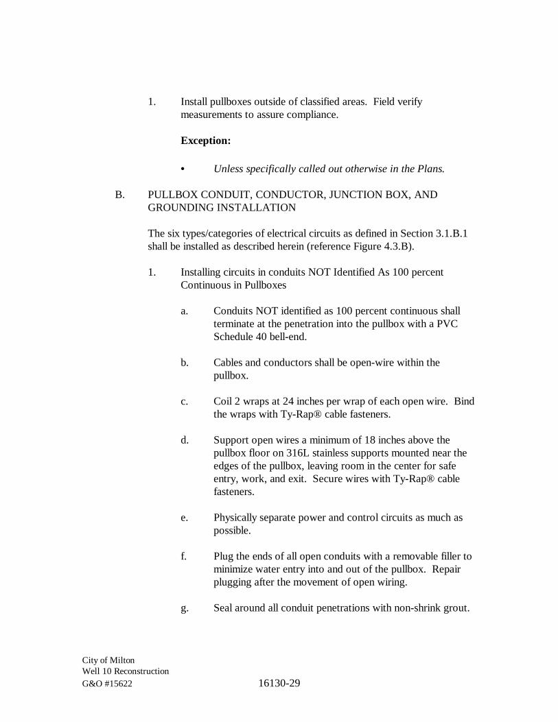
City of MiltonWell 10 ReconstructionG&O #15622 16130-29
1. Install pullboxes outside of classified areas. Field verifymeasurements to assure compliance.
Exception:
· Unless specifically called out otherwise in the Plans.
B. PULLBOX CONDUIT, CONDUCTOR, JUNCTION BOX, ANDGROUNDING INSTALLATION
The six types/categories of electrical circuits as defined in Section 3.1.B.1shall be installed as described herein (reference Figure 4.3.B).
1. Installing circuits in conduits NOT Identified As 100 percentContinuous in Pullboxes
a. Conduits NOT identified as 100 percent continuous shallterminate at the penetration into the pullbox with a PVCSchedule 40 bell-end.
b. Cables and conductors shall be open-wire within thepullbox.
c. Coil 2 wraps at 24 inches per wrap of each open wire. Bindthe wraps with Ty-Rap® cable fasteners.
d. Support open wires a minimum of 18 inches above thepullbox floor on 316L stainless supports mounted near theedges of the pullbox, leaving room in the center for safeentry, work, and exit. Secure wires with Ty-Rap® cablefasteners.
e. Physically separate power and control circuits as much aspossible.
f. Plug the ends of all open conduits with a removable filler tominimize water entry into and out of the pullbox. Repairplugging after the movement of open wiring.
g. Seal around all conduit penetrations with non-shrink grout.
City of MiltonWell 10 ReconstructionG&O #15622 16130-30
2. Installing Conduits Identified As 100 Percent Continuous inPullboxes
a. All conduits identified as 100 percent continuous passingthrough, or terminating in, a pullbox shall terminate in aTYPE J1, TYPE J2, or TYPE J3 junction box for pullingpurposes, termination, and rerouting.
b. Provide separate junction boxes for the types of circuitslisted below. Under no circumstance shall these circuittypes be combined in a common junction box.
i. Non-linear power circuits (TYPE J1).
ii. Intrinsically safe circuits (TYPE J2). Note:intrinsically safe instrumentation and control circuitsmay be combined in TYPE J2 junction boxes.
iii. Instrumentation circuits, not intrinsically safe (TYPEJ3).
c. All conduit entries into junction boxes shall be watertight,made with Myer-type hubs.
d. All conduits shall be mounted and supported with 316Lstainless steel hardware.
e. Conduit composition and protective coating shall be perSections 3.1 and 3.2.

City of MiltonWell 10 ReconstructionG&O #15622 16130-31
TYPE J1, J2, J3 JUNCTION BOX
MYER-TYPE HUBS (TYP.)
LFMC
BELL END
PVC COATED RGS
PVC SCHEDULE 40
NON-SHRINK GROUTPENETRATION SEAL
PULLBOX WALL
316L STAINLESS STEELOPEN WIRE SUPPORT STRUCTURE
DRIP FITTING
24" (MIN.) T.O.F.
18" (MIN.) T.O.F.
Figure 4.3.B
Typical Conduit Penetrations in Pullboxes
3. Installing Junction Boxes in Pullboxes
a. Junction boxes shall be NEMA 4X, 316L stainless steel, 18"x 18" x 6" (minimum) and shall comply with NEC314.28(A)(1) and 314.28(A)(2).
b. Junction boxes shall be mounted with 316L stainless steelhardware at a height of 24 inches minimum from the bottomof the junction box to the floor of the pullbox.
c. Junction boxes shall be mounted on separate walls.
d. Junction boxes shall be provided with a water drip fittingmounted to the bottom of the box.
e. Coil 4 wraps at 12 inches per wrap of each cable andconductor in a junction box.
f. Splicing shall not be allowed in junctions boxes.

City of MiltonWell 10 ReconstructionG&O #15622 16130-32
Exception:
· Unless specifically called out otherwise in thePlans.
4. Installing Grounding in Pullboxes
Reference Specification 16060.
4.4 EQUIPMENT VAULTS
A. EQUIPMENT VAULT INSTALLATION
Install vaults for underground raceway systems true to line and grade.Provide a compacted foundation of 3/8-inch minus crushed rock for thesupport of the vault. The minimum size for the foundation gravel base is6 inches greater in each direction of the length and width of the vault and6-inches deep. Ground vaults as per Section 16060-3.
B. EQUIPMENT VAULT CONDUIT INSTALLATION
Reference Figure 4.4.B.
1. All conduits entering an equipment vault shall terminate in ajunction box.
Exception:
· Unless specifically called out otherwise in the Plans.
2. Conduit composition and protective coating shall be perSections 3.1 and 3.2.
3. Conduits NOT identified as 100 percent continuous shall changefrom PVC to PVC-Coated RGS at least 24 inches before enteringthe equipment vault.
4. Conduits identified as 100 percent continuous shall terminate in aTYPE J1, TYPE J2, or TYPE J3 junction box.
a. Provide separate junction boxes for the types of circuitslisted below. Under no circumstance shall these circuittypes be combined in a common junction box.

City of MiltonWell 10 ReconstructionG&O #15622 16130-33
i. Non-linear power circuits (TYPE J1).
ii. Intrinsically safe circuits (TYPE J2). Note:intrinsically safe instrumentation and control circuitsmay be combined in TYPE J2 junction boxes.
iii. Instrumentation circuits, not intrinsically safe (TYPEJ3).
5. All conduit entries into junction boxes shall be watertight, madewith Myer-type hubs.
6. All conduits shall be mounted with 316L stainless steel hardware.
7. Conduits entering an equipment vault shall connect to theequipment through a wall-mounted junction box.
8. Conduits shall enter the vault below the junction box and connectto the box through a conduit “T” with a drain fitting as shown.Moisture from the conduit shall not be allowed to enter the junctionbox.
Exceptions:
· Conduits in classified vaults shall be provided with aconduit seal-off fitting and may enter the vault at or abovethe junction box.
· Conduits in non-classified vaults may enter the vault at orabove the height of a junction box if the conduit “T” withdrain fitting is replaced with a conduit seal-off fitting. Thisfitting may be filled with a removable product but shall beproperly filled to eliminate the possibility of the passage ofwater or water vapor.
9. Seal around all conduit penetrations with non-shrink grout.
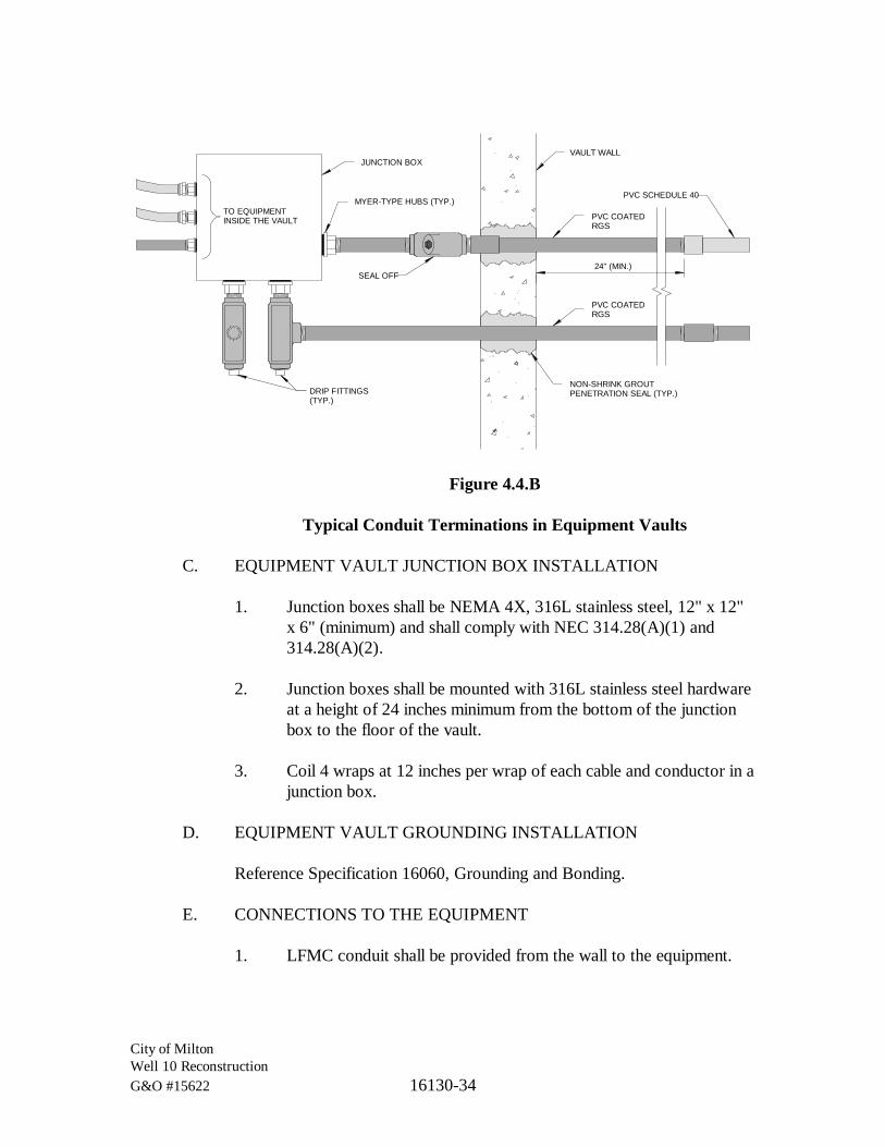
City of MiltonWell 10 ReconstructionG&O #15622 16130-34
JUNCTION BOX
PVC COATEDRGS
NON-SHRINK GROUTPENETRATION SEAL (TYP.)
VAULT WALL
MYER-TYPE HUBS (TYP.)
PVC COATEDRGS
24" (MIN.)
PVC SCHEDULE 40
SEAL OFF
TO EQUIPMENTINSIDE THE VAULT
DRIP FITTINGS(TYP.)
Figure 4.4.B
Typical Conduit Terminations in Equipment Vaults
C. EQUIPMENT VAULT JUNCTION BOX INSTALLATION
1. Junction boxes shall be NEMA 4X, 316L stainless steel, 12" x 12"x 6" (minimum) and shall comply with NEC 314.28(A)(1) and314.28(A)(2).
2. Junction boxes shall be mounted with 316L stainless steel hardwareat a height of 24 inches minimum from the bottom of the junctionbox to the floor of the vault.
3. Coil 4 wraps at 12 inches per wrap of each cable and conductor in ajunction box.
D. EQUIPMENT VAULT GROUNDING INSTALLATION
Reference Specification 16060, Grounding and Bonding.
E. CONNECTIONS TO THE EQUIPMENT
1. LFMC conduit shall be provided from the wall to the equipment.
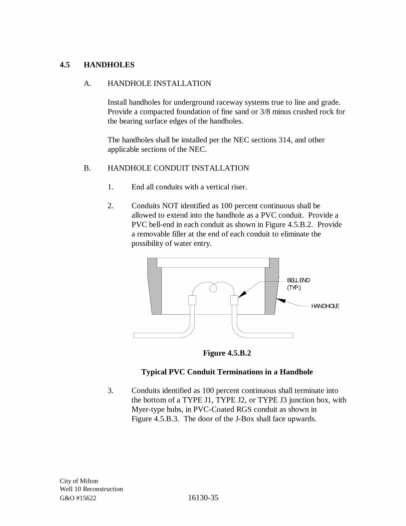
City of MiltonWell 10 ReconstructionG&O #15622 16130-35
4.5 HANDHOLES
A. HANDHOLE INSTALLATION
Install handholes for underground raceway systems true to line and grade.Provide a compacted foundation of fine sand or 3/8 minus crushed rock forthe bearing surface edges of the handholes.
The handholes shall be installed per the NEC sections 314, and otherapplicable sections of the NEC.
B. HANDHOLE CONDUIT INSTALLATION
1. End all conduits with a vertical riser.
2. Conduits NOT identified as 100 percent continuous shall beallowed to extend into the handhole as a PVC conduit. Provide aPVC bell-end in each conduit as shown in Figure 4.5.B.2. Providea removable filler at the end of each conduit to eliminate thepossibility of water entry.
BELL END(TYP.)
HANDHOLE
Figure 4.5.B.2
Typical PVC Conduit Terminations in a Handhole
3. Conduits identified as 100 percent continuous shall terminate intothe bottom of a TYPE J1, TYPE J2, or TYPE J3 junction box, withMyer-type hubs, in PVC-Coated RGS conduit as shown inFigure 4.5.B.3. The door of the J-Box shall face upwards.

City of MiltonWell 10 ReconstructionG&O #15622 16130-36
J-BOX
MYER-TYPE HUBS(TYP.)
HANDHOLE
Figure 4.5.B.3
Typical 100 Percent Continuous Conduit Terminations in a Handhole
Exception:
· Where a handhole contains only two conduits, and is beingused solely as a pulling point, where one conduit is simplyan extension of the other, a junction box may be replacedwith a PVC-Coated RGS conduit pulling body.
C. HANDHOLE GROUNDING
1. All handholes with metal conduits or with metal lids shall begrounded per Section 16060-3.
4.6 INSTALLATION OF CONDUITS UNDERGROUND AND IN CONCRETE
A. UNDERGROUND RACEWAYS
1. The minimum conduit depth shall be 24 inches.
Exceptions:
· Electrical utility conduit depth shall be 36 inches.
· Unless required otherwise by utility company.
· Unless required to be shallower due to physical constraints(see requirements below).
· Unless under a concrete slab (see requirements below).

City of MiltonWell 10 ReconstructionG&O #15622 16130-37
· Conduits contains a grounding electrode conductor shallbe 30-inches deep.
2. Conduits that require a buried depth of less than 18 inches shallrequire a 6-inch-thick concrete covering over that portion of suchconduits. Such concrete covers need not be formed but shall becolored red or shall be painted red on top.
3. Conduits under a concrete slab-on-grade shall be separated fromthe slab and from the supporting soil by at least 3 inches with softsand on all sides.
4. Provide separation of underground instrumentation conduits frompower and control conduits by a minimum of 12 inches. Avoidparallel runs of instrumentation conduits with power and controlconduits as much as possible. Where instrumentation conduits arerequired to crossover power or control conduits, maintain the12-inch separation using depth and make the crossover as close to90 degrees as possible.
Exception:
· Provide 18 inches of separation between instrumentationconduits and non-linear power conduits.
5. Run conduits as straight as practicable. Make changes in directionand/or grade of sufficient length to allow a gradual change (3-footradius minimum). Make slight offsets with 5-degree couplings.
6. Run trenches true and clear of stones or soft spots. Place 4-inchesof fine sand in the trench bottom and tamp into place. Providepreformed plastic spacers on top of sand spaced 5-feet on center.
After the raceway is placed in the trench, backfill 6 inches withsand, then with native earth backfill passing a No. 8 sieve, free ofstones. Do not tamp on top of the conduit until the final backfill isplaced. Tamp or water-settle the final backfill to finish the grade.Compact the backfill as specified under Section 02300 “SiteEarthwork.”
7. Mark direct buried conduit by placing a red marking tape aminimum of 12 inches below grade during backfilling of the trench.
8. Seal conduit connections to eliminate leakage.

City of MiltonWell 10 ReconstructionG&O #15622 16130-38
B. CONCRETE ENCASED RACEWAYS
Raceways encased in structural concrete must be defined in detail andpresented to the Structural Engineer for approval at least 7 days prior toinstallation. As a minimum, approval will be based on the assurance thatthere will be no physical interference and that structural integrity will notbe jeopardized.
1. In general, conduits encased in concrete may take the most directroute providing they do not jeopardize the structural integrity of theslab or interfere with process-related piping or equipment.
2. Conduits shall be at least 1-1/2 inches to the edge of a concretebody. If a structural block-out is desired for conduit bundling nearthe edge of a concrete body, then submit the desired layout to theEngineer for approval and design as defined in this Section.
3. Conduit density, crossover, and routing must be minimized andcoordinated to assure that structural integrity is not jeopardized.
4. At the point-of-exposure out of the slab, conduits must beperpendicular to the slab surface from all angles.
5. No part of an elbow’s bending radius shall be seen at the point-of-exposure from the slab.
C. CONDUITS IN ELEVATED SLABS
See “CONCRETE ENCASED RACEWAYS” above.
D. CONDUITS UNDER SLABS ON GRADE
1. No conduits will be encased in slabs less than 8 inches in depth.
2. For slabs-on-grade, all conduits larger than 3/4-inch trade size mustbe run underground below the slab.
3. All conduits desired to be installed within slabs on grade shall besubmitted to the Engineer for approval and design as defined in thisSection.

City of MiltonWell 10 ReconstructionG&O #15622 16130-39
Exceptions:
· Conduits shown on the Plans as being designed into slabson grade do not require further Engineering approval.
E. CONDUIT TRANSITIONS
Where raceway exits from grade or concrete, provide the following:
1. All conduits exiting grade or concrete shall be PVC-Coated RGS.
Exception:
· Raceways used for the containment and protection of baregrounding electrode conductors shall be PVC Schedule 80.No portion of these conduits shall be metallic.
2. For equipment to be moved into place at a later date, install a PVC-Coated RGS coupling flush with the floor slab. Insert a threadedflush plug into the coupling. Provide a pull wire looped backed intothe conduit that can be reached after removal of the plug.
3. Only the straight portion of conduits shall exit grade or concrete.No curved portion of a factory or field-bent conduit shall be visibleexisting the penetration, even when covered or hidden byequipment.
F. CONDUIT STUB-UPS INTO EQUIPMENT AND ENCLOSURES
1. Where conduits are stubbed up into open bottom equipment andenclosures, extend the bottom of the conduit threads 1/2 inch abovegrade. Provide ground bushing and end fittings, flush with fittingand 2-inch stub, above the bottom of the enclosure. Stub conduitsto a uniform height (plus or minus 1/8 of an inch) and align withinplus or minus 1/4 inch.
Exception:
· Conduits that do not meet the requirements of being100 percent continuous, stubbing up directly under a MotorControl Center that is mounted on a housekeeping pad,shall be allowed to terminate as a PVC conduit with a bell-end.

City of MiltonWell 10 ReconstructionG&O #15622 16130-40
2. Locate stub-ups directly under the section gutter into which theconductors they contain are to be routed. Terminate conduit withinsulating, grounding type bushing bonded to the ground bus of theequipment.
3. Protect stub-ups from damage where conduits rise through floorslabs. Arrange so curved portion of bends are not visible above thefinished slab.
4. Unless otherwise noted on the Plans, spare conduits stubbing upthrough concrete floors and not adjacent to a wall shall be finishedflush with floor with an RGS coupling. Provide an in-set metalplug (male thread) into coupling flush with floor.
5. Unless otherwise noted on the Plans, spare conduits stubbing upthrough concrete floors or grade, and adjacent to a wall orhousekeeping pad shall extend 12 inches above slab/grade. Theexterior edge of the conduit shall be a minimum of 1 inch from thewall/pad.
6. All stub-ups shall be provided with pull string.
7. Provide conduit labels on all stub-ups which are not flush mounted.
4.7 PROTECTION
Provide final protection and maintain conditions, in a manner acceptable tomanufacturer and installer that ensures coatings, and finishes are without damageor deterioration at the time of Substantial Completion.
A. Repair damage to galvanized finishes with zinc-rich paint recommended bymanufacturer.
B. Repair damage to PVC or paint finishes with matching touchup coatingrecommended by manufacturer.
4.8 CLEANING
On completion of installation, including outlet fittings and devices, inspect exposedfinish. Remove burrs, dirt, and construction debris and repair damaged finish,including chips, scratches, and abrasions.

City of MiltonWell 10 ReconstructionG&O #15622 16130-41
4.9 QUALITY CONTROL
A. TESTS
1. Conduits identified as meeting the requirements of 100 percentcontinuity shall be tested between source and destination asfollows:
a. Testing shall be performed using a Digital Voltmeter orBiddle ohmmeter.
b. Testing values shall not exceed 5 ohms.
c. If testing values exceed 5 ohms, then corrective action shallbe taken to reduce the resistance to 5 ohms or below.
d. These measurements shall be documented, signed, andsubmitted to the Engineer for approval.
*** END OF SECTION ***

City of MiltonWell 10 ReconstructionG&O #15622 16140-1
SECTION 16140
WIRING DEVICES
PART 1 GENERAL
1.1 SCOPE
The work specified in this Section includes the various types of receptacles,connectors, switches, and finish plates.
1.2 RELATED WORKS SPECIFIED ELSEWHERE
Section Items16050 Basic Electrical Materials and Methods16130 Raceways and Boxes
1.3 SUBMITTALS
See Section 01300.
1.4 QUALITY ASSURANCE
See Section 16050.
1.5 COORDINATION
A. WIRING DEVICES FOR OWNER FURNISHED EQUIPMENT
Match devices to plug connectors for Owner-furnished equipment.
B. CORD AND PLUG SETS
Match cord and plug sets to equipment requirements.
1.6 DEFINITIONS
Reference Section 16050, “Definitions.”

City of MiltonWell 10 ReconstructionG&O #15622 16140-2
PART 2 PRODUCTS
2.1 MANUFACTURERS
A. AVAILABLE MANUFACTURERS
Subject to compliance with requirements, manufacturers offering productsthat may be incorporated in the work include the following:
1. Wiring Devices
a. Arrow Hart Div., Cooper Industries.
b. Bryant Electric, Inc.
c. Hubbell Inc.
d. Killark Electrical Mfg. Co.
e. Leviton Mfg. Co., Inc.
f. Pass & Seymour/Legrand.
2. Multi-Outlet Assemblies
a. Wiremold Co.
2.2 WIRING DEVICES
Comply with NEMA Standard WD 1, “General Purpose Wiring Devices.”Terminals shall be rated for 75 degrees C (min.).
A. ENCLOSURES
NEMA 1 equivalent, except as otherwise indicated.
B. COLOR
Ivory except as otherwise indicated or required by Code.

City of MiltonWell 10 ReconstructionG&O #15622 16140-3
C. RECEPTACLES, STRAIGHT-BLADE AND LOCKING TYPE
Except as otherwise indicated, comply with Federal Specification W-C-596and heavy-duty grade of UL Standard 498, “Electrical Attachment Plugsand Receptacles.” Provide NRTL labeling of devices to verify compliance.
1. General Purpose Convenience Outlets
a. Duplex receptacle configuration
b. Nylon face
c. Staked screw terminals for line, neutral, and groundconnections.
d. Provisions for split bus
e. NEMA 5-20R
2. Special Purpose Receptacles
a. Staked screw terminals for line, neutral, and groundconnections.
b. NEMA configuration as indicated.
D. RECEPTACLES, STRAIGHT-BLADE, SPECIAL FEATURES
Comply with the basic requirements specified above for straight-bladereceptacles of the class and type indicated, and with the followingadditional requirements:
1. Ground-Fault Circuit Interrupter (GFCI) Receptacles – Class A(5 mA) Personal Profection
UL Standard 943, “Ground Fault Circuit Interrupters,” withintegral NEMA 5-20R duplex receptacle arranged to protect onlythe connected receptacle and no other receptacles connected on thesame circuit. Design units for installation in a 2-3/4-inch-deepoutlet box without an adapter.

City of MiltonWell 10 ReconstructionG&O #15622 16140-4
E. RECEPTACLES, INDUSTRIAL HEAVY-DUTY
Conform to NEMA Standard PK 4 “Plugs, Receptacles, and CableConnectors of the Pin and Sleeve Type for Industrial Use.”
F. SNAP SWITCHES
Quiet-type ac switches, NRTL listed and labeled as complying with ULStandard 20 “General Use Snap Switches,” and with Federal SpecificationW-S-896.
1. Lighting Switches
120/277 Vac only, rated 20 amperes.
G. WALL PLATES
Single and combination types that mate and match with correspondingwiring devices. Features include the following:
1. Color
Matches wiring device except as otherwise indicated.
2. Plate-Securing Screws
Metal with heads colored to match plate finish.
3. Material for Exterior or Wet Locations: Cast Aluminum.
PART 3 EXECUTION
3.1 INSTALLATION
A. IDENTIFICATION
Each receptacle, whether convenience, or dedicated, shall be labeled withthe circuit from which its power is derived. Label as “CKT-XX” whereXX = numerical circuit number
1. Only one Panelboard servicing the site:
Label as “CKT-XX” where XX = numerical circuit number withinthe Panelboard.

City of MiltonWell 10 ReconstructionG&O #15622 16140-5
2. More than one Panelboard servicing the site:
Label as “CKT XX-YY” where XX = Panelboard number and YY= numerical circuit number within the Panelboard.
Example:A receptacle powered from circuit 03 of Panelboard [01 PB 02]would be labeled “CKT 02-03”
B. RECEPTACLE BOXES
1. Reference Section 16130 for box types.
2. Mounting Height
a. Outdoor
Outdoor receptacle boxes shall be mounted 18 inches abovegrade unless shown otherwise on the Plans.
3. Reference Section 16130 for box cover types.
C. CONVENIENCE RECEPTACLES
Convenience receptacles shall be 20 A, duplex, white, GFCI, straight blade,3-wire, grounding, unless called out otherwise on the Plans.
In addition to any GFCI requirements, all receptacles, convenience ordedicated, located in break rooms and kitchens shall be AFCI.
D. DEDICATED RECEPTACLES
Dedicated receptacles shall be 20 A, simplex, gray, non-GFCI, straightblade, 3-wire, grounding, unless called out otherwise on the Plans.
Power must be connected to a dedicated GFCI breaker in the panelboard.
In addition to any GFCI requirements, all receptacles, convenience ordedicated, located in break rooms and kitchens shall be AFCI.
Dedicated receptacles shall include a red phenolic placard with 3/8-inchlettering over the receptacle stating:
City of MiltonWell 10 ReconstructionG&O #15622 16140-6
NON-GFCI RECEPTACLEFOR (specific device)
NOT INTENDED FOR GENERAL USE
E. ARRANGEMENT OF DEVICES
Except as otherwise indicated, mount flush, with long dimension vertical,and grounding terminal of receptacles on bottom. Group adjacent switchesunder single, multigang wall plates.
1. See “Raceways and Boxes” Section for mounting height of devices.
2. Verify locations of outlets and switches in cabinetry with cabinetsupplier and Owner prior to installation.
F. INSTALLATION PRACTICES
1. Install devices and assemblies plumb, level, flush and secure.Provide spacers on device screws to flush yokes or flanges tosurface of wall within 1/16 of an inch where boxes are not flushwith the wall surface. Install wiring devices such as receptacles towithstand 50 pounds force applied perpendicular to the device facewith a maximum deflection of 1/16 of an inch.
2. Protect devices and assemblies during painting.
3. Use corrosion resistant devices in kitchen areas and outdoors.
4. Wiring connections shall be made by compression on the screwterminals. The wire shall be neatly and symmetrically wrappedaround the screw a minimum of 180 degrees.
G. LIGHT SWITCH ORIENTATION
Install switches with the “off” position down. Install three and four wayswitches so the load is “off” when all switch handles are down.
H. TERMINATION PRACTICES
Connect phase, neutral, and grounding wires to devices with full loopsaround screws installed to tighten with tightening of the screw. Triminsulation to within 1/8 of an inch of screw terminal.

City of MiltonWell 10 ReconstructionG&O #15622 16140-7
I. WALL PLATES
Install after painting is complete. Install with an alignment tolerance of1/16 of an inch to plumb. Install at flush mounted devices so that all fouredges are in continuous contact with finished wall surface without the useof mats or similar devices. Do not use plaster fillings.
3.2 GROUNDING
Connect receptacle or switch ground lug to device box for devices other thanisolated ground type.
3.3 FIELD QUALITY CONTROL
Test wiring devices for proper connections, polarity, and ground continuity.Perform this testing with testing equipment designed for testing polarity andconnections.
Operate each operable device at least six times.
Test ground-fault circuit interrupter operation with local fault simulations, using atester designed for such testing, and according to manufacturer recommendations.Testing with integral test switches on the receptacle is not sufficient for thistesting.
Replace damaged or defective components, and retest.
*** END OF SECTION ***

City of MiltonWell 10 ReconstructionG&O #15622 16420-1
SECTION 16420
MOTOR CONTROLLERS
PART 1 GENERAL
1.1 SCOPE
The work specified in this Section includes AC motor controllers rated 600 voltsand less that are supplied as enclosed units within motor control centers or asindividual units mounted in equipment specified under other sections.
1.2 RELATED WORK SPECIFIED ELSEWHERE
Section Items01770 Training16050 Basic Electrical Materials and Methods16120 Conductors and Cables16442 Motor Control Equipment
1.3 DEFINITIONS
A. ANALOG AMMETER
A dial-type, d’Arsenval movement, analog meter measuring motorampacity, either directly or indirectly from a current transformer connectedto one of the motor leads.
B. COMPLETE COMBINATION STARTER
The terms STARTER, MOTOR STARTER, COMBINATION MOTORSTARTER, and COMBINATION STARTER are all equivalent toCOMPLETE COMBINATION STARTER as described here.
A Complete Combination Starter consists of all power, control, andcommunication devices required to completely and safely operate a motorin HAND control. It consists of a lockable Overcurrent Protective Device(OCPD) such as a circuit breaker or a fused disconnect, a Power Module(RVSS, VFD, or Magnetic) for controlling/applying power to the motor,Motor Overload Protection (MOP) circuits, and other ancillary circuits forcomplete control and protection of the motor and starter power devices. Itincludes an enclosure with operator interface control and monitoringdevices.

City of MiltonWell 10 ReconstructionG&O #15622 16420-2
C. FST (Field Service Technician)
A Field Service Technician (FST) is a technical “hands-on” fieldrepresentative trained and certified by the starter manufacturer.
D. FVNR BYPASS CONTACTOR
In RVSS starter power circuits, an FVNR rated BYPASS CONTACTORis one whose current rating is sufficiently high to allow direct across-the-line motor starting in an FVNR mode (RVSS failure).
See RUN RATED BYPASS CONTACTOR in this section.
E. FVNR (Full Voltage Non Reversing) STARTER
FVNR starters operate motors in only one direction. These startersinstantly apply full line voltage to the motor terminals through a contactorrelay.
See MAGNETIC STARTER.
F. FVR (Full Voltage Reversing) STARTER
FVR starters operate motors in both forward and reverse directions. Thesestarters instantly apply full line voltage to the motor terminals through twoseparate (one forward and one reverse) contactor relays.
See MAGNETIC STARTER.
G. HIM (Human Interface Module)
HIM units are programmable human interfaces to RVSS and VFD drivesand are used to configure the drive protection and control options. Thesedevices are typically provided with programming/operating buttons andvisual displays.
H. IGBT (Insulated Gate Bipolar Transistors)
IGBTs are embedded devices used to provide power switching in theDC-to-AC inverter section of VFD power modules.

City of MiltonWell 10 ReconstructionG&O #15622 16420-3
I. MAGNETIC MOTOR STARTER
Because FVNR and FVR starters use an electromagnetic contactor relay totransfer power to the motor, these devices are a part of the MAGNETICSTARTER family of motor starters.
See FVNR, FVR.
J. RAMP RATE, RVSS
The RVSS ramp rate is defined as the time, in seconds, for the RVSS toincrease its voltage output from zero to full voltage or decrease its voltageoutput from full voltage to zero.
K. RAMP RATE, VFD
The VFD ramp rate is defined as the time, in seconds, for the VFD toincrease its output frequency from 0 Hz to 60 Hz or decrease its outputfrequency from 60 Hz to 0 Hz.
L. RUN-RATED BYPASS CONTACTOR
In RVSS starter power circuits, a run rated BYPASS CONTACTOR isone whose current rating is limited to the RVSS current rating. This typeof bypass contactor cannot be used to directly start the motor across-the-line.
See FVNR BYPASS CONTACTOR in this section.
M. RVSS
The RVSS is the manufacturer’s integrated power module package withoutadditional starter components, and consists of embedded electronic powerswitching devices for acceleration and deceleration, associated “firing”control circuitry, and an embedded microprocessor for power circuit firingcontrol and motor/module protection. It is one of the key components thatmake up a COMPLETE COMBINATION RVSS STARTER.
The RVSS power module may or may not include a RUN-RATEDBYPASS CONTACTOR.

City of MiltonWell 10 ReconstructionG&O #15622 16420-4
N. SCRs (Silicon Controlled Rectifiers)
SCRs are GE’s trade name for a thyristor (a four-layer unidirectionalswitching device). SCRs are triggered by the application of a gate currentand are shut off at a zero-voltage crossover.
O. “S” CURVES
A modified linear-ramp curve with rounded edges between portions of thecurve that are changing (d/dt portions) and portions of the curve that arenot changing (steady state).
d/dt portionsteady state portion
"S" curve
linear ramp
steady state portion
"S" curve
P. THD (Total Harmonic Distortion)
THD is defined as the ratio of the sum of the levels of all harmoniccomponents to the level of the fundamental frequency.
Values are limited by the IEEE 519, 1992 standard developed to minimizepower problems related to non-linear loads, such as VFDs.
1.4 SUBMITTALS
Submit under the provisions of Section 01300.
Manufacturer’s product data for motor controllers and accessories specified in thisSection.
Maintenance data for tripping devices to include in the operation and maintenancemanual specified in Section 16050.
Compile load current and overload relay list after motors have been installed andarrange to demonstrate that selection of heaters suits actual motor nameplatefull-load currents.
City of MiltonWell 10 ReconstructionG&O #15622 16420-5
1.5 QUALITY ASSURANCE
See Section 16050.
1.6 COORDINATION
Coordinate the sizing and settings of each starter’s Overcurrent Protective Device(OCPD) and Motor Overload Protection (MOP) device with associated motor’snameplate data.
The Contractor shall acquire the full and complete nameplate data for each motorand document this data for insertion into the O&M Manual. This data shall bemade available during FIELD TESTING AND COMMISSIONING work asdescribed in Section 3.5.
1.7 EXTRA MATERIALS
Reference Specification Section 16050 for spare parts.
PART 2 PRODUCTS
2.1 MANUFACTURERS
A. AVAILABLE MANUFACTURERS
Subject to compliance with requirements, manufacturers offering productsthat may be incorporated into the work include the following:
1. Allen-Bradley Co.; Industrial Control Group.
2. Eaton Corp.; Westinghouse & Cutler-Hammer Products.
3. General Electric Co.; Electrical Distribution & Control Div.
4. Square-D.
2.2 PRODUCT SHIPMENT AND STORAGE
A. PRODUCT SHIPMENT
The motor starters shall be delivered to the project’s System Integrator fortemporary connection and integrated testing with the site PLC prior tobeing delivered to the jobsite. This testing will be coordinated by the

City of MiltonWell 10 ReconstructionG&O #15622 16420-6
System Integrator and combined into a complete witness test of both thePLC and motor starter controls. All hardwire connections between thePLC(s) and the motor starters shall be tested during the witness test. Forthe test, all motor starters (whether FVNR, FVR, RVSS, or VFD) shall bepowered at their full operational voltage and shall be connected and testedagainst a voltage-rated AC squirrel cage motor. Allow for the Owner andEngineer to witness these tests. Provide a minimum of 15 days’ noticeprior to the test.
The System Integrator shall be responsible for repackaging and shipping tothe jobsite. The Contractor is responsible for unloading the shipment.
B. PRODUCT STORAGE
Motor starters, whether in MCCs or stand alone, shall be packaged,covered, and protected from weather and physical damage during storagebefore final installation.
2.3 COMBINATION MOTOR STARTERS, GENERAL
A. ENCLOSURES
1. For Starters Not Internal to MCCs
Flush- or surface-mounted cabinets as indicated. NEMA 250, Type12, unless otherwise indicated to meet environmental conditions atinstalled location.
Exception to 2:
· Unless specifically stated otherwise on the Plans.
B. COMPLIANCE
1. Standards
Motor starters shall be Underwriter’s Laboratory (UL) listed andlabeled, and comply with the latest applicable standards of ANSI,IEEE, and the National Electrical Code.
2. THD Noise Immunity and Compliance with IEEE 519-1992
Motor starters shall meet the following requirements:
City of MiltonWell 10 ReconstructionG&O #15622 16420-7
a. THD level meets the requirements of the serving electricutility and is less than 5 percent of the fundamentalvoltage/current as measured on the serving utility’selectrical system at the point of power delivery to theOwner’s facility (point of common coupling) when installedand operating at the facility (reference IEEE 519-1992, orlatest revision). Reference the Plans for the point ofcommon coupling.
b. THD level shall not cause the generator sets (provided bythe Contractor and the existing generator sets) whichsupplies standby power to the drive, or the generator setcontrols, to exceed voltage regulation of 5 percent orfrequency regulation of 3 percent, or to oscillate, hunt,jump, or otherwise operate in a manner which damages thegenerator set or generator set components.
C. GENERAL DEVICES AND COMPONENTS
All combination motor starters shall include the following devices:
1. Overcurrent Protective Device (OCPD).
a. The OCPD shall be a NEMA AB 1, motor circuit breakerprotector, magnetic only, with field-adjustable short-circuittrip-coordinated with motor locked-rotor amperes for thespecific motor being powered.
b. The OCPD shall be lockable in the OPEN position and shallinclude an auxiliary Form A contact that is open when theOCPD is electrically tripped or manually opened.
c. The OCPD shall be lockable from the front panel, withoutthe operator having to open the panel door.
d. The OCPD shall be sized by the motor controllermanufacturer for the motor being served and shall beselectively coordinated with OCPDs upstream as perSection 16410.
2. Control Devices (reference Specification 16940)
The following minimum requirements apply:

City of MiltonWell 10 ReconstructionG&O #15622 16420-8
a. Provide surge protective devices across each AC and DCrelay coil.
b. Provide control and timing relays per Section 16940.
c. Provide LED “push-to-test” indicating lights.
d. Provide combination electromechanical motor start counterand motor run time (elapsed time) meters perSection 16940. Battery backed LCD displays will not beaccepted.
e. Provide Phase Monitor Relays that monitor phase loss,phase imbalance, phase reversal, under-voltage, andover-voltage, with a Form A contact that is active on any ofthese conditions.
Exception:
· Programmable starters that provide the PhaseMonitor Relay functions as described above do notrequire an additional discrete phase monitor relay.
f. Door-Mounted Devices
Provide door-mounted devices as specifically shown on thePlans.
Door-mounted devices, such as elapsed time meters, motorstart counters, indicating lights, ammeters, selectorswitches, reset pushbuttons, etc., shall not be replaced withelectronic panel functions.
g. Devices Mounted Internal to the Enclosure
Motor starters shall include all components and devicesnecessary to provide the electrical control functionalityshown on the Motor Starter Elementary Wiring Diagramson the Plans.
Electromechanical relays and timers shall not be replacedwith electronic logic functions.
City of MiltonWell 10 ReconstructionG&O #15622 16420-9
Exceptions to 2:
· Unless specifically approved by the Engineer.
3. Control Circuit Requirements
a. Control functions shall match those shown on the MotorStarter Elementary Diagrams including manual requirementsby the operators.
Provide additional circuits and devices as required by thestarter manufacturer for power circuit isolation; however,these additions shall not change the features or functionalityof the intended design.
b. Provide additional fusing or device protection as required toprotect the drive’s electronic power and control circuits andto comply with UL requirements.
c. Motor starters shall be provided with independent fused“control power” circuits. A fault in one motor controlcircuit shall only disable that associated motor.
i. Motor starter control circuits shall be 120 volts AC.
ii. If motor power is derived from 480 Vac, then eachcontrol circuit shall be provided with an independentcontrol transformer with a 120-volt AC fusedsecondary. The fuse shall be factory mounted to thetop of the transformer.
iii. Motor starter control circuits may include remotepanel heaters, motorized dampers, blower enclosurecooling fans, or other small power devices. Size thecontrol transformers and fuses to handle allconnected loads shown on the Plans plus anadditional 25 percent.

City of MiltonWell 10 ReconstructionG&O #15622 16420-10
2.4 RVSS MOTOR STARTERS
Reference section COMBINATION MOTOR STARTERS, GENERAL
A. THD NOISE IMMUNITY AND COMPLIANCE WITH IEEE 519-1992
Reference Section 2.3B.
B. THE POWER CIRCUIT
1. Overcurrent Protective Device (OCPD).
Reference GENERAL DEVICES AND COMPONENTS,Section 2.3C.
2. The RVSS.
a. Provide a Run-Rated Bypass Contactor.
Exception:
· Where specifically called out as an FVNR-RatedBypass Contactor on the Plans.
b. Provide any additional power contactors and associatedlogic control, as required by the specific manufacturer, forpower circuit isolation.
c. Heat sink cooling fans shall be ball bearing type withinternal impedance protection for the fan motor.
d. All printed circuit boards shall be coated with a non-siliconebase coating and shall be rated for wet applications.
e. The circuit board and SCRs shall be noise immune perIEC 947-4-2, EMC requirements.
f. Electrical Specifications
i. Voltage Ratings: as shown on the Plans.
ii. Input voltage variations: ±25 percent of nominalmotor voltage, at a frequency of 58 to 62 Hz.

City of MiltonWell 10 ReconstructionG&O #15622 16420-11
iii. Operating Temperature: to 50 degrees C(122 degrees F) without derating.
50 to 70 degrees C (122 to 158 degrees F) derating33 percent for every 10 degrees C over50 degrees C to a maximum of 70 degrees C.
iv. Permissible Altitude: 1,000 m at rated current
v. Humidity: 5 to 95 percent relative humidity,non-condensing.
vi. Overload Ratings Duration
%FLA @ 50°C (s) @ 25°C (s)600 10 15500 20 30450 30 45300 120 180200 480 720115 Continuous Continuous
“Light duty” controllers are not acceptable.
vii. Power Devices
Power semiconductors shall be SCRs connected ininverse parallel configuration in each phase(six SCRs for 3-phase systems).
(a) Peak Inverse Voltage (PIV) ratings shall beas follows:
200 to 480 V units: 1,400 V PIV200 to 600 V units: 1,600 V PIV
(b) Firing circuitry shall utilize optical isolatedgate circuitry for hard firing of SCRs. Pulsetransformers and “picket fence” firing are notacceptable. The gate drive circuit shall beoptically coupled for noise immunity andlong life.

City of MiltonWell 10 ReconstructionG&O #15622 16420-12
viii. Voltage Transient Suppression
(a) Metal Oxide Varistors (MOVs) shall besupplied as standard across the powerdevices to protect them from line transients.Voltage transient suppression shall not causethe power devices to turn on. Built-in MOVprotection shall prevent the MOVs fromoutgassing when rating is exceeded.
(b) Resistor-capacitor snubber networks shall besupplied as standard to prevent the powerdevices from misfiring due to the dV/dTcharacteristics of the SCRs.
3. Motor Overload Protection (MOP).
The following overload protection shall be integrated into theRVSS or provided as a separate device within the combinationstarter.
a. Intelligent Overload Relay Protection
Where motor starters are shown on the Plans to benetworked together or to a PLC, either directly or throughnetwork switches, such combination motor starters shallinclude the functionality of Intelligent Overload Relayscomplete with communication equipment and protocolscompatible with the approved system control PLC.Functionality shall include ambient temperaturecompensation, visible trip indication, selectable tripClasses of 10, 15, 20, and 30, selectablemanual/auto-manual reset, stall and jam protection withseparate adjustable delays, phase imbalance, phase reversal,and phase loss, undervoltage, overvoltage, and underloadsensing with conditional shutdown.
C. THE CONTROL CIRCUIT
Reference GENERAL DEVICES AND COMPONENTS, Section 2.3C.
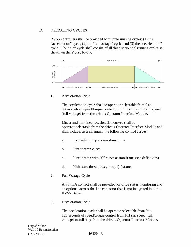
City of MiltonWell 10 ReconstructionG&O #15622 16420-13
D. OPERATING CYCLES
RVSS controllers shall be provided with three running cycles; (1) the“acceleration” cycle, (2) the “full voltage” cycle, and (3) the “deceleration”cycle. The “run” cycle shall consist of all three sequential running cycles asshown on the Figure below.
ACCELERATION CYCLE DECELERATION CYCLEFULL VOLTAGE CYCLE
RUN CYCLE
MO
TOR
VO
LTA
GE
FULLVOLTAGE
0 V
1. Acceleration Cycle
The acceleration cycle shall be operator-selectable from 0 to30 seconds of speed/torque control from full stop to full slip speed(full voltage) from the drive’s Operator Interface Module.
Linear and non-linear acceleration curves shall beoperator-selectable from the drive’s Operator Interface Module andshall include, as a minimum, the following control curves:
a. Hydraulic pump acceleration curve
b. Linear ramp curve
c. Linear ramp with “S” curve at transitions (see definitions)
d. Kick-start (break-away torque) feature
2. Full Voltage Cycle
A Form A contact shall be provided for drive status monitoring andan optional across-the-line contactor that is not integrated into theRVSS Drive.
3. Deceleration Cycle
The deceleration cycle shall be operator-selectable from 0 to120 seconds of speed/torque control from full slip speed (fullvoltage) to full stop from the drive’s Operator Interface Module.

City of MiltonWell 10 ReconstructionG&O #15622 16420-14
Operator selection of 0 seconds shall result in a “natural coasting”deceleration to full stop.
Linear and non-linear deceleration curves shall beoperator-selectable from the drive’s Operator Interface Module andshall include, as a minimum, the following control curves:
a. Hydraulic pump deceleration curve
b. Linear ramp curve
c. Linear ramp with “S” curve at transitions
4. Run Cycle
A Form A contact shall be provided that is continuously active overthe acceleration, full voltage, and deceleration cycles.
E. FACTORY SETTINGS
Acceleration and deceleration values shall be preconfigured by the startermanufacturer for each RVSS starter as follows:
Ramp Rates(0-100% speed), in sec.
Tag Number Description Accel. Decel.[10 MTR 01] MOTOR, WELL No. 1 5 5
F. RVSS I/O TERMINALS
The RVSS shall include, as a minimum, the following I/O connectionterminals:
Signal I/O Type FunctionDrive “START” Input Input, 120 Vac RVSS “Start” CommandDrive “RESET” Input Input, 120 Vac RVSS “Reset” Command
Drive Fault Output Output, Form A or C ProgrammableDrive Running Output Output, Form A or C ProgrammableDrive at Full-Speed Output Output, Form A or C Programmable
G. NETWORK COMMUNICATIONS
Where motor starters are shown on the Plans to be networked together orto a PLC, either directly or through network switches, such RVSS
City of MiltonWell 10 ReconstructionG&O #15622 16420-15
combination motor starters shall include communications equipment andprotocols compatible with the approved system control PLC.
Provide the minimum command and status parameters as shown on theschematic(s) and I/O tables on the Plans.
Provide additional distributed I/O modules and associated power supplies,as required, to meet the data transfer networking requirements listed hereand shown on the schematic(s) and I/O tables on the Plans.
2.5 EXTRA MATERIALS
A. Reference Specification 16050 for spare parts.
PART 3 EXECUTION
3.1 APPLICATION
Apply motor starters as described on the Plans.
3.2 INSTALLATION
Install independently mounted motor control devices according to manufacturer’swritten instructions and the NEC.
A. IDENTIFICATION
Identify motor control components and control wiring according toSection 16050.
B. LOCATION AND MOUNTING
Locate controllers as shown on the Plans. Provide the mounting methodsfor each separate starter enclosure as shown on the Plans. ReferenceSection 16050.
3.3 WIRING INSTALLATION
A. Install wiring between motor control devices according to Section 16120.
B. Bundle, train, and support wiring in enclosures.
City of MiltonWell 10 ReconstructionG&O #15622 16420-16
C. Make all control wiring connections to provide a complete and operationalsystem. Provide additional terminals, wire guides, and gutters as requiredfor a safe and protected system.
3.4 CONNECTIONS
Tighten connectors, terminals, bus joints, and mountings. Tighten field-connectedconnectors and terminals including screws and bolts according to manufacturer’spublished torque-tightening values. Where manufacturer’s torque values are notindicated, use those specified in UL 486A and UL 486B.
3.5 FIELD TESTING AND COMMISSIONING
A. GENERAL TESTING REQUIREMENTS
1. Testing procedures described herein shall apply to all startersassociated with the Project.
2. Complete testing of motor starters shall be provided and shallinclude:
a. The services of a qualified independent testing agency toperform breaker testing as described below.
b. The assistance of the starter manufacturer’s Field ServiceTechnician (FST) as described below.
3. Motor starter tests shall also be coordinated with the followingrepresentatives:
a. The System Integrator,
b. The motor/pump Manufacturer,
c. The Engineer,
d. The Owner.
B. TESTING PROCEDURES BEFORE MAKING ELECTRICALCONNECTIONS TO THE STARTER (FST ASSISTANCE NOTREQUIRED)
1. Megger the motor leads per Specification 16120.

City of MiltonWell 10 ReconstructionG&O #15622 16420-17
2. If the starter is powered from a separate feeder, then megger thefeeder per Specification 16120.
3. For molded case circuit breakers 100 amps and larger, provideindependent testing agency to perform circuit breaker tests as statedin NETA ATS, Section 7.6. Certify compliance with testparameters. Provide the Engineer a copy of the test results signedby testing agency.
4. Perform visual and mechanical inspection of enclosure and devices.Remove and replace damaged units with new.
5. Connect power, control, instrumentation, and communicationconductors to the motor starter. Verify the integrity of allconnections.
6. Remove any burrs, filings, or other foreign materials fromenclosure.
7. Completely wipe down and vacuum enclosure.
C. ENGAGING THE FST AT THE JOBSITE PRIOR TO ENERGIZATION
Engage an FST to be present when energizing or commissioning motorstarters. Under the direction of the FST, the following minimum tests shallbe performed, documented, and dated by the FST. These documents willbe provided as a part of the MCC or Motor Starter Sections of the O&MManual.
The FST shall:
1. Check connections and device mounting for proper torque.
2. Check alignment of plug-in devices with stationary parts.
3. Check operating mechanisms for binding, lubrication, etc.
4. Verify that all pilot lights are LED type. Replace if not.
5. Verify that analog meters are scaled roughly two times the motor’sFLA.
6. Test the validity of the control, instrumentation, andcommunication circuits.

City of MiltonWell 10 ReconstructionG&O #15622 16420-18
7. Test all breakers for proper physical movement and doorinterlocking. Repair or replace as required.
8. Set the motor protection values for the specific motors beingcontrolled.
9. Verify the drive’s initial minimum and maximum speed ranges perthe table in Section 2.6F.
10. Set the acceleration and deceleration rates per the tables inSection 2.5 and Section 2.6, FACTORY SETTINGS, for RVSSand VFD units respectively.
11. The FST shall energize the starter.
D. SERVICES OF THE FST AT THE JOBSITE AFTER ENERGIZATION
The FST shall:
1. Verify motor rotation and direction. Coordinate this work with thepump/motor manufacturer. Wiring corrections shall be made by theContractor.
2. Test the starter protection circuits.
3. Test the starter RESET control.
4. Test the starter for proper operation and functionality per design.Verify manual and automatic speed controls and transfers.
5. In coordination with the pump or blower manufacturer, the Owner,and the Engineer, run VFD-controlled motors through theirminimum and maximum speed ranges. Identify the frequencies atwhich the motor speeds cause excessive resonant frequencyvibrations (as determined by the pump/blower manufacturer).Identify the frequencies just above and below the resonantfrequency and program the VFD drive to lock out the band offrequencies in between (the “notch frequencies”). Perform this taskfor each resonant frequency. Document the lower and upperfrequencies of the lockout bands.

City of MiltonWell 10 ReconstructionG&O #15622 16420-19
6. Test the starter network communications and functionality withassociated PLC or network controller. Coordinate this work withthe System Integrator.
7. Test all starter digital and analog I/O connectivity, functionality,and scaling with the PLC, whether hardwired or networked.Coordinate this work with the System Integrator.
8. Test starter cooling fan circuits.
9. Test minimum and maximum speeds.
10. Correct malfunctioning units on site where possible and retest todemonstrate compliance; otherwise, remove and replace with newunits and retest.
E. ADJUSTMENTS AND STARTER PERFORMANCE VERIFICATIONBY THE FST
1. The FST shall provide adjustments, calibrations, and final settingsfor RVSS units, VFD drives, and Motor Overcurrent Protective(MOP) devices as required to meet design intent and processrequirements and make all necessary adjustments and calibrations asrequired to provide acceptable motor starting and operationalperformance. Motor nameplate data shall be provided to the FSTby the Contractor.
2. The FST shall provide the final OCPD breaker trip setting for themotor circuit being protected.
3. The FST shall document all such adjustments and calibrations in atable similar to that shown below (as a minimum) and initial anddate each final setting. This table shall be submitted to Engineeringfor approval and acceptance. All Status “As Left” conditions mustbe checked off as “OK” before completion. The final table shall beprovided as a part of the MCC or Motor Starter Sections of theO&M Manual.
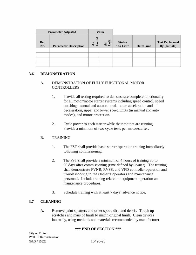
City of MiltonWell 10 ReconstructionG&O #15622 16420-20
Parameter Adjusted Value
Ref.No. Parameter Description A
sFo
und
As
Lef
t Status“As Left” Date/Time
Test PerformedBy (Initials)
3.6 DEMONSTRATION
A. DEMONSTRATION OF FULLY FUNCTIONAL MOTORCONTROLLERS
1. Provide all testing required to demonstrate complete functionalityfor all motor/motor starter systems including speed control, speednotching, manual and auto control, motor acceleration anddeceleration, upper and lower speed limits (in manual and automodes), and motor protection.
2. Cycle power to each starter while their motors are running.Provide a minimum of two cycle tests per motor/starter.
B. TRAINING
1. The FST shall provide basic starter operation training immediatelyfollowing commissioning.
2. The FST shall provide a minimum of 4 hours of training 30 to90 days after commissioning (time defined by Owner). The trainingshall demonstrate FVNR, RVSS, and VFD controller operation andtroubleshooting to the Owner’s operators and maintenancepersonnel. Include training related to equipment operation andmaintenance procedures.
3. Schedule training with at least 7 days’ advance notice.
3.7 CLEANING
A. Remove paint splatters and other spots, dirt, and debris. Touch upscratches and mars of finish to match original finish. Clean devicesinternally, using methods and materials recommended by manufacturer.
*** END OF SECTION ***

City of MiltonWell 10 ReconstructionG&O #15622 16440-1
SECTION 16440
PANELBOARDS
PART 1 GENERAL
1.1 SCOPE
The work specified in this Section consists of lighting, power, and distributionpanelboards, and associated auxiliary equipment rated 600 V and less.
1.2 RELATED WORKS SPECIFIED ELSEWHERE
Section Item01300 Submittals16050 Basic Electrical Materials and Methods16060 Grounding and Bonding
1.3 SUBMITTALS
Submit under the provisions of Section 01300.
A. PRODUCT DATA
For each type of panelboard, accessory item, and component specified.
B. SHOP DRAWINGS
For panelboards. Include dimensioned plans, sections, and elevations.Show tabulations of installed devices, major features, and voltage rating.Include the following:
1. Enclosure type and mounting.
2. Bus configuration and current ratings.
3. Short-circuit current rating of panelboard.
4. Features, characteristics, ratings, and factory settings of individualprotective devices and auxiliary components.

City of MiltonWell 10 ReconstructionG&O #15622 16440-2
C. PANELBOARD SCHEDULES
For installation in panelboards and inclusion in the maintenance manualsspecified in Division 1. Submit final versions prior to closeout of project.
D. MAINTENANCE DATA
For panelboard components to include in the maintenance manualsspecified in Division 1. Include manufacturer’s written instructions fortesting circuit breakers.
1.4 QUALITY ASSURANCE
See Section 16050.
Subject to compliance with requirements, provide products by the following:
A. REFERENCED STANDARDS
1. National Electrical Manufacturers Association (NEMA):
a. NEMA 250, Enclosures for Electrical Equipment(1,000 Volts Maximum).
b. NEMA PB 1, Panelboards.
2. National Fire Protection Association (NFPA):
a. 70, National Electrical Code (NEC).
3. Underwriters Laboratories, Inc. (UL):
a. 50, Standard for Safety Cabinets and Boxes.
b. 67, Standard for Safety Panelboards.
1.5 EXTRA MATERIALS
Reference Specification Section 16050 for spare parts.

City of MiltonWell 10 ReconstructionG&O #15622 16440-3
PART 2 PRODUCTS
2.1 MANUFACTURERS
A. MANUFACTURERS
Subject to compliance with requirements, provide products by thefollowing:
1. General Electric Co.; Electrical Distribution & Control Div.
2. Eaton, Cutler-Hammer.
3. Siemens Energy & Automation, Inc.
4. Square D Co.
2.2 PANELBOARD FABRICATION
A. MANUFACTURED UNITS
Standards: NEMA PB 1, NFPA 70, UL 50, UL 67.
B. RATINGS
1. Bus current, voltage, number of phases, and number of wires asshown on the Plans.
2. Short Circuit Fault Rating
a. 250 Vac or Less
10 kAIC minimum short circuit rating or as indicated on thePlans, whichever is the greater.
3. Service Entry Equipment rated when indicated on the Plans.
C. BUS BARS
1. Main Bus Bars
a. Plated drawn copper of 98 percent conductivity sized tolimit temperature rise to a maximum of 65 degrees C abovean ambient temperature of 40 degrees C.
City of MiltonWell 10 ReconstructionG&O #15622 16440-4
b. Drilled and tapped and arranged for sequence phasing of thebranch circuit devices.
2. Ground Bus
a. Ground bus shall be full size (100 percent) rated unlessshown otherwise on the Plans.
b. Ground bus shall be bonded to the box.
c. Provide additional isolated ground bus when indicated onthe Plans.
d. Compression type connectors.
3. Neutral Bus Bars
a. Insulated, full size (100 percent) rated unless shownotherwise on the Plans.
b. Compression type connectors.
D. CONSTRUCTION
1. Interiors shall be factory assembled and designed such thatswitching and protective devices can be replaced without disturbingadjacent unit and without removing the main bus connectors.
E. ENCLOSURES
1. Boxes
a. Code gauge galvanized steel, furnished without knockouts.
2. Trim Assembly
a. Code gauge galvanized steel, finished with rust-inhibitedprimer and manufacturer’s standard paint inside and out.
3. Distribution, Lighting and Appliance Panelboard
a. Trims supplied with hinged door over all circuit breakerhandles.
City of MiltonWell 10 ReconstructionG&O #15622 16440-5
b. Trims for surface mounted panelboards shall be the samesize as the box.
c. Trims for flush mounted panelboards shall overlap the boxby 3/4 inch on all sides.
d. Doors on panelboard front, with concealed hinges, securedwith corrosion resistant chrome-plated flush catch andtumbler lock, all keyed alike.
e. Nominal 20-inch wide by 5-3/4-inch deep with gutter spacein accordance with NEC.
f. Clear plastic cover for directory card on the inside of eachdoor.
g. Enclosure
i. Outdoor Locations: NEMA 3R unless statedotherwise on the Plans.
F. SERVICE EQUIPMENT APPROVAL
Listed for use as service equipment for panelboards with main servicedisconnect.
1. Future Devices
Equip with mounting brackets, bus connections, and necessaryappurtenances, for the overcurrent protective device ampere ratingsindicated for future installation of devices.
G. SPECIAL FEATURES
Include the following features for panelboards:
1. Skirt for Surface-Mounted Panelboards
Same gage and finish as panelboard front, removable, with flangesfor attachment to panelboard, wall, and floor.

City of MiltonWell 10 ReconstructionG&O #15622 16440-6
H. Provide same size boxes for multisection panelboards.
1. Extra Gutter Space
Dimensions and arrangement as indicated.
2. Subfeed
Overcurrent protective device or lug provision as indicated.
3. Feed-through Lugs
Sized to accommodate feeders indicated.
4. Main Breaker: Vertical mounting.
2.3 OVERCURRENT AND SHORT CIRCUIT PROTECTIVE DEVICES
A. MAIN OVERCURRENT PROTECTIVE DEVICE
1. Molded-Case Circuit Breaker, NEMA AB 1, handle lockable.
2. Vertical mounting unless stated otherwise in the Plans.
B. BRANCH OVERCURRENT PROTECTIVE DEVICES
1. Shall be bolt-on molded case circuit breakers
2. The minimum breaker size shall be 15 Amp unless stated otherwiseon the Plans.
3. Characteristics
a. Frame size, trip rating, number of poles, and auxiliarydevices as indicated on the Plans.
b. Fault current rating as defined herein and as indicated on thePlans.
c. Where branch circuit breakers are shown on the Plans to beGFCI the GFCI shall be Class A (5 mA), sometimes called a“Personal Protection” GFCI.

City of MiltonWell 10 ReconstructionG&O #15622 16440-7
4. Application Listing
a. Appropriate for application, including Type SWD forswitching fluorescent lighting loads and Type HACR forheating, air-conditioning, and refrigerating equipment.
5. Circuit breakers, under 200 A
a. Thermal-magnetic, trip-free, non-interchangeable, non-adjustable.
6. Lugs
a. Mechanical lugs and power-distribution connectors forcopper conductors of number and size indicated.
PART 3 EXECUTION
3.1 INSTALLATION
Install panelboards and accessory items according to NEMA PB 1.1.
Setup, adjust and fasten in place flush trim and interiors.
Install circuit breakers as shown on the “Panelboard Schedule” for eachpanelboard. Record all circuit breaker installation deviations from the “PanelboardSchedule” and show on the Record Drawings the actual size and pole position ofall circuit breakers installed.
Do not remove knockouts for breaker positions unless a breaker is to be installed(reference EXTRA MATERIALS, UNUSED CIRCUITS in this Section). Wheretwistouts or knockouts are removed in error, provide a circuit breaker (one pole,20-ampere) to fill each position removed.
A. MOUNTING HEIGHTS
Top of trim 74 inches above finished floor, unless otherwise indicated.
B. MOUNTING
Plumb and rigid without distortion of box. Mount flush panelboardsuniformly flush with wall finish. Provide spacers of neoprene or fiberglassto shim out from irregular surfaces or from damp surfaces.
City of MiltonWell 10 ReconstructionG&O #15622 16440-8
C. CIRCUIT DIRECTORY
Prepare neatly typewritten panelboards directories in the same polesequence as the panelboard stamping. Send a copy to the Owner for hisrecords. Prior to typing the final directories, verify room and equipmentnames and numbers with the Owner and modify circuit descriptions ofareas/spaces to conform with the Owner’s desires. Obtain approval beforeinstalling.
D. PROVISION FOR FUTURE CIRCUITS
Install panelboards in such a manner as to leave access to the box, buildingchases, knockouts, etc., for future circuit additions. Place conduit in therear line of knockouts where possible. Install spare conduits from flush-mounted panels up to accessible spaces.
E. WIRING IN PANELBOARD GUTTERS
Run neatly parallel and perpendicular to enclosure. Arrange conductorsinto groups, and bundle and wrap with wire ties.
3.2 IDENTIFICATION
Identify field-installed wiring and components and provide warning signs asspecified in Section 16050.
Label each panelboard with engraved laminated-plastic or metal nameplatesmounted with corrosion-resistant screws.
3.3 GROUNDING
Connect equipment grounding conductors to ground bus, except for circuitsrequiring isolated grounding.
Provide ground continuity to main electrical ground bus as indicated.
3.4 CONNECTIONS
Tighten electrical connectors and terminals, including grounding connections,according to manufacturer’s published torque-tightening values. Wheremanufacturer’s torque values are not indicated, use those specified in UL 486Aand UL 486B.

City of MiltonWell 10 ReconstructionG&O #15622 16440-9
3.5 FIELD QUALITY CONTROL
A. Prepare for acceptance tests as follows:
1. Make insulation-resistance tests of each panelboard bus,component, and connecting supply, feeder, and control circuits.
2. Make continuity tests of each circuit.
B. TESTING AGENCY
Provide services of a qualified independent testing agency to performspecified testing.
C. TESTING
1. Prior to Energization
Perform visual and mechanical inspection of panelboard, bus, andbreakers.
Check connections and mounting for proper torque.
For molded case circuit breakers 100 Amps and larger, provideindependent testing agency to perform circuit breaker tests as statedin NETA ATS, Section 7.6. Certify compliance with testparameters.
Provide to the Engineer separate copies of test results signed bytesting agency. Include the manufacturer’s circuit breaker curve foreach breaker tested.
Correct or replace malfunctioning units and retest.
Remove any burrs, filings, or other foreign materials. Completelywipe down and vacuum panelboard.
2. After Energization
After electrical circuitry has been energized, demonstrate productcapability and compliance with requirements.

City of MiltonWell 10 ReconstructionG&O #15622 16440-10
Correct malfunctioning units on site where possible and retest todemonstrate compliance; otherwise, remove and replace with newunits and retest.
3.6 ADJUSTING
Set field-adjustable switches and circuit-breaker trip ranges as indicated.
*** END OF SECTION ***
City of MiltonWell 10 ReconstructionG&O #15622 16460-1
SECTION 16460
LOW VOLTAGE TRANSFORMERS
PART 1 GENERAL
1.1 SCOPE
Step down transformer [10 XMFR 01] will be provided by the Owner. TheContractor shall disconnect and relocate [10 XMFR 01] from its existing locationwithin the Well 10 building prior to the building’s demolition and reinstall thetransformer per the installation requirements contained within this submittal.
1.2 RELATED WORKS SPECIFIED ELSWHERE
Section Item01300 Submittals16050 Basic Electrical Materials and Methods
PART 2 EXECUTION
2.1 INSTALLATION
Comply with safety requirements of IEEE C2.
Arrange equipment to provide adequate spacing for access and for circulation ofcooling air.
Tighten electrical connectors and terminals according to manufacturer’s publishedtorque-tightening values. If manufacturer’s torque values are not indicated, usethose specified in UL 486A and UL 486B.
2.2 GROUNDING
Comply with NFPA 70 requirements for connecting to grounding electrodes andfor bonding to metallic piping near the transformer.
Comply with Division 16 Section “Grounding and Bonding” for materials andinstallation requirements.

City of MiltonWell 10 ReconstructionG&O #15622 16460-2
2.3 FIELD QUALITY CONTROL
Test to ensure transformer is operational within industry and manufacturer’stolerances, is installed according to the Contract Documents, and is suitable forenergizing.
A. REPORT
Submit a written report of observations and tests. Report defectivematerials and installation.
B. TESTS
Include the following minimum inspections and tests according tomanufacturer’s written instructions.
1. Inspect accessible components for cleanliness, mechanical andelectrical integrity, and damage or deterioration. Verify thattemporary shipping bracing has been removed. Include internalinspection through access panels and covers.
2. Inspect bolted electrical connections for tightness according tomanufacturer’s published torque values or, if not available, thosespecified in UL 486A and UL 486B.
3. Insulation Resistance: Perform megohmmeter tests of primary andsecondary winding to winding and winding to ground.
C. TEST FAILURES
Compare test results with specified performance or manufacturer’s data.Correct deficiencies identified by tests and retest. Verify that transformersmeet specified requirements.
2.4 CLEANING
On completion of installation, inspect components. Remove paint splatters andother spots, dirt, and debris. Repair scratches and mars on finish to match originalfinish. Clean components internally using methods and materials recommended bymanufacturer.

City of MiltonWell 10 ReconstructionG&O #15622 16460-3
2.5 ADJUSTING
After installing and cleaning, touch up scratches and mars on finish to matchoriginal finish.
Adjust transformer taps to provide optimum voltage conditions at utilizationequipment throughout normal operating cycle of facility. Record primary andsecondary voltages and tap settings and submit with test results.
*** END OF SECTION ***

City of MiltonWell 10 ReconstructionG&O #15622 16940-1
SECTION 16940
CONTROL PANELS
PART 1 GENERAL
1.1 SCOPE
The work specified in this Section includes motor control panel [10 MCP 01].[10 CP 01] is designed by the System Integrator under a separate contractfollowing the City of Milton standards.
1.2 RELATED WORKS SPECIFIED ELSEWHERE
Section Item01300 SubmittalsDivision 16 Electrical
1.3 DEFINITIONS
A. CONTROL PANELS
Reference Section 16050.
B. CONTROL POWER
Control power is considered electrical power at either 120 VAC or24 VDC that powers control or instrumentation devices. Control powercircuits are less than 150 VAC and less than or equal to 20 Amps.
Examples:
1. 120 VAC or 24 VDC device power to instruments such as flowmeters, chlorine analyzers, dissolved oxygen transmitters, and etc.
2. 120 VAC or 24 VDC device power to control devices such asPLCs, radios, network switches, and etc.
3. 120 VAC power to control devices such as motor operated valves,metering pumps (even when through dedicated receptacles),lighting circuits (controlled within a lighting control panel), andetc.

City of MiltonWell 10 ReconstructionG&O #15622 16940-2
1.4 REFERENCES
Reference TitleNEMA National Electrical Manufacturers AssociationICS-1 General Standards for Industrial Control and SystemsICS-4 Terminal Blocks for Industrial UseICS-6 Enclosures for Industrial Controls and SystemsPublication No. 250 Enclosures for Electrical Equipment (1000 V maximum)NFPA National Fire Protection AssociationNEC National Electric CodeJIC-EMP-1 Joint Industrial Council
1.5 SYSTEM DESCRIPTION
A. CONTROL PANELS
1. Reference Section 16050, Definitions.
2. Control panels shall be fabricated similar to those shown on thePlans. With the exception of the discrete and analog I/O terminalblocks, the exact dimensions and component layout is not critical.
3. The system includes new control panels for control of processequipment. Some of the control panels are provided underDivision 16. Some panels are provided under other Divisions withequipment specified in those Divisions. Control panels, whetherprovided under Division 16 or other Divisions, shall meet therequirements of this Section.
1.6 SUBMITTALS
A. SHOP DRAWINGS
1. See Section 01300.
2. Dimensioned or to-scale panel layout drawings.
3. Materials of construction.
4. Drawings showing conduit and wiring access locations.
5. Elementary wiring diagrams and terminal block drawings,differentiating between panel and field wiring.
City of MiltonWell 10 ReconstructionG&O #15622 16940-3
6. Bill of Materials describing the reference name or number,quantity, complete English language description, manufacturer,model number, local supplier, and wiring or piping reference.Information shall include manufacturer name, catalog descriptions,wiring and piping diagrams, dimensional plans, anchoring details,installation instruction, and test results.
7. Loop diagrams with all components connected per ISA standards.
8. Nameplate text.
9. Heat calculations and relationship to enclosure fan, heater, airconditioner.
10. UPS system loading and resulting back-up run time.
B. OPERATION AND MAINTENANCE MANUALS
1. See Section 01300.
2. Provide manufacturer’s operating and maintenance manuals foreach device or item provided.
3. Recommended spare parts stocking list.
C. CONTRACTOR CERTIFICATION
1. The Contractor fabricating panels shall submit proof ofcertification as a UL 508 and/or UL 698A (if required) panel shop.
1.7 QUALITY ASSURANCE
A. Make shop drawings available prior to placement of conduits in slabs toensure placement is coordinated with panel access locations.
B. Test panels prior to shipment to project site.
1. The entire assembled panel shall be tested to be free from groundsand shorts.
2. Controllers, circuits, and interlocks shall be rung out and tested toassure that they function correctly before the panel is shipped.Prior to placement of conduit feeds, assure approved control panellayouts are available.
City of MiltonWell 10 ReconstructionG&O #15622 16940-4
C. Panels supplied under this Section are provided by a single manufacturer.
D. Provide panels labeled by a recognized testing laboratory or otherwiseacceptable to the State of Washington Department of Labor and Industriesmeeting the requirements of Article 409 of the NEC. In addition, allcompleted panels shall be UL listed.
E. Revise all drawings upon completion of the work to show “as shipped”condition of the panel.
1.8 STORAGE AND HANDLING
A. After completion of shop assembly and testing, enclose panels inheavy-duty polyethylene envelopes or secured sheeting to providecomplete protection from dust and moisture. Place dehumidifiers insidethe polyethylene covering.
B. Skid-mount the equipment for final transport. Show shipping weight onshipping tags, together with instructions for unloading, transporting,storing, and handling on job site.
1.9 EXTRA MATERIALS
Reference Specification Section 16050 for spare parts.
PART 2 PRODUCTS, MATERIALS
2.1 CONTROL PANEL ENCLOSURES
A. ENCLOSURE BODIES
Control panel enclosures are factory UL labeled enclosures fabricated ofstretcher leveled steel welded into a rigid, self-supporting structure.Control panels shall be completely enclosed, welded construction, self-supporting, and gasketed dust-tight.
1. Panels mounted outdoors or in below-ground vaults shall beNEMA 4X 316L stainless steel.
Exception:
· Unless indicated otherwise in the Plans.

City of MiltonWell 10 ReconstructionG&O #15622 16940-5
B. HINGES AND HINGE PINS
1. Provide full length (continuous) piano hinges rated for 1.5 timesthe weight of the door plus all door-mounted instruments.
2. Hinges shall be welded to all surfaces and shall match themetallurgy of the enclosure.
3. Hinge pins shall be 316L stainless steel on all panels.
C. MOUNTING FEET
If called for, mounting feet shall be the height indicated on the Plans andshall be made of the same material as the enclosure body that it supports.
2.2 CONTROL PANEL POWER DEVICES
A. FUSES
1. Power Circuit Fusing
Reference Specification 16410, Enclosed Switches, Fuses, andCircuit Breakers.
2. Control Power Fusing
Control power fuses are FRN for ratings above 10 amperes andFNQ for 10 amperes and below. FRN fuses are mounted inphenolic blocks with a fuse puller mounted adjacent to them. FNQfuse holders are DIN-rail mounted type, 12A, 300 V minimum,hinged to disconnect and replace fuse, with blown fuse indicatinglight. Label all fuseholders with fuse identification number andfuse size and type. Provide five spare fuses of each type and sizein each panel. Provide box mounted on panel interior marked“SPARE FUSES” to hold the spares.
B. CIRCUIT BREAKERS
1. Power Circuit Breakers
Reference Specification 16410, Enclosed Switches, Fuses, andCircuit Breakers.

City of MiltonWell 10 ReconstructionG&O #15622 16940-6
2. Control Power Circuit Breakers
Control power circuit breakers shall be DIN-rail mounted type,miniature, 240 VAC, single pole, 10 kAIC (minimum) @240 VAC, “C” curve (inductive) trip characteristics, 1,500 VACdielectric strength (minimum), #14 to #12 AWG 75oC line andload screw terminals, UL 489, CSA 22.2 No. 5.1; Allen BradleyBulletin 1492-SPU Series A or equal.
C. DISCONNECT SWITCHES AND ACTUATORS
1. For Power Circuits > 30 Amps
Reference Specification 16410, Enclosed Switches, Fuses, andCircuit Breakers.
2. For Power Circuits <= 30 Amps
a. For Single Phase Circuits
Load disconnect switches shall be 2-position, OFF-ON, 90degree, 600 VAC, 20 A or 32 A rating, single pole, frontdoor installation; Allen Bradley 194L-E aa-1751 or equal,where aa = 20 for 20 A unit and aa = 32 for 32 A unit.
Associated switch actuators shall be OFF-ON, 90 degree,front/door installation, IP66 rated, 22.5 mm central holemount, square, red/yellow handle with padlock provision,48 mm x 48 mm; Allen Bradley 194L-HC4L-175I or equal.
b. For Three Phase Circuits
Load disconnect switches shall be 2-position, OFF-ON, 90degree, 600 VAC, 20 A or 32 A rating, 4-pole, front doorinstallation; Allen Bradley 194L-E aa-1754 or equal, whereaa = 20 for a 20 A unit and aa = 32 for a 32 A unit.
Load disconnect switch actuators shall be OFF-ON, 90degree, front/door installation, IP66 rated, 22.5 mm centralhole mount, square, grey/black handle with padlockprovision, 64 mm x 64 mm; Allen Bradley 194L-HC6E-175I or equal.

City of MiltonWell 10 ReconstructionG&O #15622 16940-7
When being used as a 3 PH motor safety disconnect switch,reference Specification 16410, Enclosed Switches, Fuses,and Circuit Breakers.
3. For Control Power Circuits
Control power SPDs shall protect L-N, L-G and N-G and have aminimum peak surge current of 40kA, shall have terminals thataccept a #12 AWG conductor, shall be rated for the voltage shownin the Plans, shall be UL listed, and shall have a terminalconfiguration with separate Line, Neutral, and Groundconnections.
Control power SPDs shall meet Mil-Std-220 for maximumEMI/RFI attenuation.
Control power SPDs shall be DIN-rail mounted, 1-inch widemaximum.
Control power SPDs shall be Innovative Technology HS-DIN-120series or equal.
D. PHASE MONITOR RELAYS (PMRS)
1. PMRs shall only be used on 3 phase power systems and shall becompatible with the voltage configuration as shown on the Plans.For 240 VAC 3 phase systems, the high leg shall be phase B.
2. PMRs shall monitor the following conditions and provide theability to adjust trip values and time delays as described below:
a. Phase Loss
i. Trip not adjustable
ii. Time delay not adjustable, fixed at 100 msec.
b. Phase Reversal
i. Trip not adjustable
ii. Time delay not adjustable, fixed at 100 msec.

City of MiltonWell 10 ReconstructionG&O #15622 16940-8
c. Phase Unbalance
i. Trip adjustable, set at 10 percent
ii. Time delay not adjustable, fixed at 2 seconds.
d. Under voltage
i. Trip adjustable, set at 80 percent of nominal voltage
ii. Time delay adjustable, set at 5 seconds.
e. Overvoltage
i. Trip not adjustable, fixed at 110 percent of nominalvoltage
ii. Time delay not adjustable, fixed based on inversetime.
3. PMRs shall be provided with 1x SPDT (Form C) dry isolatedcontact that transitions when thresholds are exceeded for timedelays described above.
4. PMRs shall be: Automation Direct, Prosense, PMRU-1C-480A orequal.
E. MOTOR START COUNTERS/MOTOR RUN TIME (ELAPSED TIME)METERS
When the control panel contains motor starters, start counter and run timemeter shall be a combination electromechanical device. Eaton CEC-55PM-406 or equal. Battery backed LCD displays shall not be used.Refer to Specification 16420, Motor Controllers.
F. CURRENT TRANSFORMERS
Current transformers are 1 percent accuracy at burden and lead length asinstalled. G.E., Midwest, Westinghouse or Hawkeye.
G. AMMETERS
Ammeters are ±2 percent accuracy, 2-1/2-inch size GE, Simpson, Weston,or Crompton.
City of MiltonWell 10 ReconstructionG&O #15622 16940-9
2.3 CONTROL PANEL CONTROL DEVICES
A. PILOT LIGHTS
1. Pilot lights shall be heavy duty, Class 9001, Type J, NEMA 4(watertight) and NEMA 13 (oil-tight), metal collar, push-to-test,multi-segmented LED with red, green, amber, blue, clear, white, oryellow colored caps as shown on the Plans.
a. Allen-Bradley
b. Cutler-Hammer
c. General Electric
d. Siemens
e. Square D
B. PUSH BUTTONS
1. Push buttons shall be heavy duty, Class 9001, Type K, UL Types 4and 13, NEMA 4 (watertight) and NEMA 13 (oil-tight), metalcollar, non-illuminating, with full button guard. Contact blockshall be provided with 1 N.O. and 1 N.C. contacts minimum withthe ability to stack additional blocks. Provide additional blocks asrequired.
Pushbutton actuators may be standard, mushroom head, recessed(flush collar), or deep recessed (deep collar) as required.
a. Allen-Bradley
b. Cutler-Hammer
c. General Electric
d. Siemens
e. Square D

City of MiltonWell 10 ReconstructionG&O #15622 16940-10
C. SELECTOR SWITCHES
1. Hand-Off-Auto (HOA) Selector Switches
HOA selector switches shall be Class 9001, Type K, UL types 4and 13, NEMA 4 (watertight) and NEMA 13 (oil-tight), metalcollar, non-illuminating push button contact blocks with 3-positionoperators and standard knob. Contact block shall be provided with2 N.O. and 2 N.C. contacts minimum with the ability to stackadditional blocks. Provide additional blocks as required.
The 3-position operator shall be manual rotation to left and rightfrom center and manual return back to center. Two contact blockstacks shall be provided. In both contact block stacks, one set ofcontacts is closed in the left position and open in the center andright positions. In both contact block stacks, one set of contacts isclosed in the right position and open in the center and leftpositions.
a. Allen-Bradley
b. Cutler-Hammer
c. General Electric
d. Siemens
e. Square D
2. Reset-Off-On Selector Switches
RESET-OFF-ON selector switches shall be Class 9001, Type K,UL types 4 and 13, NEMA 4 (watertight) and NEMA 13(oil-tight), metal collar, non-illuminating push button contactblocks with 3-position operators and standard knob. Contact blockshall be provided with 2 N.O. and 2 N.C. contacts minimum withthe ability to stack additional blocks. Provide additional blocks asrequired.
The 3-position operator shall be manual rotation to left and rightfrom center, spring return from left to center and manual returnfrom right to center. Two contact block stacks shall be provided.In both contact block stacks, one set of contacts is closed in the leftposition and open in the center and right positions. In both contact
City of MiltonWell 10 ReconstructionG&O #15622 16940-11
block stacks, one set of contacts is closed in the right position andopen in the center and left positions.
a. Allen-Bradley
b. Cutler-Hammer
c. General Electric
d. Siemens
e. Square D
D. RELAYS
Regardless of the technology of a relay’s control (from simple toprogrammable), the relay’s output technology shall be the electro-mechanical type. Electronic outputs (triacs, thyristors, transistors, etc.)shall not be allowed.
Exceptions:
· Unless specifically shown otherwise on the Plans.
· Unless approved in writing by the Engineer.
1. Contactor relays
Contactor relays for switching 120 VAC power circuits including,but not limited to, lighting, solenoid valves, and small motors shallbe electro-mechanical machine tool, heavy-duty type, NEMArated, with 120 VAC/24 VDC coils and double-break contactsrated at 20 A at 250 VAC. Equip relays with surge suppressers.IEC rated relays are not permitted.
2. Control relays
Control relays for logic control circuits shall be permitted to beminiature “ice cube” type DPDT or 4PDT with 24V or 110-120VAC/DC coils with a mechanical life of 20 million operationsminimum and an electrical life of 1 million operations minimum at1 amp. The dielectric strength between the coil and contacts shallbe 2,000 VAC for 1 minute. Contacts shall be rated at 10A at250 VAC, 10A at 30 VDC. Relays shall have a maximum pickupand release time of 25 milliseconds and a minimum drop voltage

City of MiltonWell 10 ReconstructionG&O #15622 16940-12
of 30 percent of the rated voltage. Relays shall includenon-polarized LED coil indictors. Relays shall be IDEC,P&B/Tyco or equal.
3. Time delay relays
Time delay relays shall be electronic, programmable, multifunctiontype with a minimum of two Form C time-delay contacts; CrouzetChronos 2 or equal.
Time delay relays shall be capable of TDAE and TDAD functionsas a minimum.
Time delay relays shall be provided with selectable time ranges inseconds, minutes, and hours and adjustable settings within therange.
Provide a signal isolation relay for those TDAD timers that requirean isolated trigger (see figure above). G&O schematics and wiringdiagrams will show the equivalent timer connection as seen in thefigure below.

City of MiltonWell 10 ReconstructionG&O #15622 16940-13
2.4 CONTROL PANEL ANCILLARY DEVICES
A. RECEPTACLES MOUNTED IN CONTROL PANELS
120 VAC power to convenience and device receptacle in control panelsshall not be derived from the same panelboard circuit as that used forprocess control devices (PLC, flow meters, autodialers, DC powersupplies, etc.).
1. Convenience Receptacles
Convenience receptacles in control panels are not dedicated andare intended for providing 120 VAC convenience power for non-motor-operated equipment.
Convenience receptacles shall be GFCI, 15 Amp, 125 VAC,duplex, white, in a DIN-rail mount, cast aluminum box. Stampedsteel boxes shall not be used.
2. Device Receptacles
Device receptacles are dedicated for communication and controldevices operating within the control panel on a continuous basis.These include devices with 120 VAC power packs like VPNs,Fiber-To-Voice Converters, Data-To-Voice Converters, and etc.
Device receptacles shall be non-GFCI, 15 Amp, 125 VAC, duplex,white, in a DIN-rail mount, cast aluminum box. Stamped steelboxes shall not be used.
On Communication Patch Panels, these receptacle circuits can beextended with surge- and load-protected power strips.
B. PANEL LIGHTING
For all panels so designated on the Plans, provide an LED lightingpackage, under cabinet style, hardwired, 120 VAC, with integral door-activated ON/OFF switch.
120 VAC power to the panel light shall not be derived from the samePanelboard circuit as that used for process control devices (PLC, flowmeters, autodialers, DC power supplies, etc.).

City of MiltonWell 10 ReconstructionG&O #15622 16940-14
C. PANEL HEATER
Provide a panel heater with thermostat in each outdoor control panel andall panels so designated on the Plans. Each heater shall include a DIN-railmounted disconnect breaker and associated feedthrough and groundingterminals for connection to external 120 VAC line, neutral, and groundconductors. The heater and thermostat shall be prewired to these terminalsand breaker.
The wattages shown below are minimum values. The Contractor shallsize the panel heaters based on enclosure size, internal load heatgeneration, minimum operating temperature of devices in the enclosures,and minimum ambient temperature. Contractor shall include panelheating calculations with control panel submittals.
For panels with a front surface area greater than 11 square feet, provide atouch-safe, 550 watt minimum, 120 VAC panel heater with integralthermostat.
D. PANEL COOLING FANS
Provide a panel cooling system in enclosures that contain motor starters,drives, PLCs, RTUs, and other electronic devices that can generate heatand have maximum operating temperature limits unless specifically shownotherwise in the Plans. The panel cooling system shall include one ormore fans with a thermostat as a minimum. The cooling system shall besufficiently sized to maintain an internal enclosure temperature below themaximum operating temperature of all internal devices.
Provide a thermostat for cooling, N.O. contact, adjustable setpoint range32 to 140 degrees F, 15 Amp-rated contact at 120 VAC.
Cooling fans shall be configured to exhaust air. Vents shall be providedfor supply air. Layout fans and vents in such a manner as to:
1. Maximize cooling of critical components;
2. Minimize air flow restriction;
3. Eliminate entry of water or dust particles into the enclosure.
Provide vent covers over fan and vent openings to eliminate rain andmoderate washdown for all outdoor panels and all panels so designated onthe Plans.

City of MiltonWell 10 ReconstructionG&O #15622 16940-15
Provide a “washdown filter” fan set, capable of eliminating sprayed waterentry, stainless steel, 120 VAC, 310 CFM, 3.8 Amps max., 18" x 10" x 5".
120 VAC power to panel fans shall not be derived from the samepanelboard circuit as that used for process control devices (PLC, flowmeters, autodialers, DC power supplies, etc.).
E. PANEL WIRING PRODUCTS
1. Power Circuit Wiring; Reference Specification 16120.
2. Control Circuit Wiring; Reference Specification 16120.
3. Analog PLC I/O Wiring
Signal cables connected completely inside control panels betweenanalog input and output field terminal groupings and theirassociated PLC analog cards shall be #22 AWG, stranded, tinnedcopper, twisted pair, 300 V, 100 percent overall foil shielded cablewith #22 AWG tinned copper drain wire; Belden #8451 or equal.
2.5 CONTROL PANEL ACCESSORIES
A. PANEL NAMEPLATES AND IDENTIFICATION
1. Identify each item on the control panel with rectangularnameplates.
2. Provide nameplates of rigid phenolic plastic laminate withengraved lettering or engraved metal plate with filled lettering.Use black background with white lettering.
3. Minimum letter height is 1/2 inch for instrument description and1/4-inch height for instrument tag number.
4. Provide each panel with a 2-inch by 10-inch (minimum) nameplatewith 1-inch-high lettering with panel identification.
5. Abbreviations are not permitted unless approved by the Owner orspecifically shown on the nameplates, schedules, or plans.
6. Install nameplates plumb and parallel to the lines of doors orstructure to which they are attached. Attach to the sheet metalstructure by a thin coat of adhesive and sheet metal screws. Makeadhesive and screw applications in such a manner as to avoid

City of MiltonWell 10 ReconstructionG&O #15622 16940-16
nameplate buckling or distortion due to use of excessive adhesiveor over tightening of screws.
PART 3 INSTALLATION
3.1 FABRICATION
A. GENERAL
1. Control panels are factory or shop fabricated units completelyassembled, wired, and tested before shipment to the job site.
2. Panel construction, in general, meets JIC EMP-1 standards andapplicable NEMA and IEEE standards.
Exception:
· Where open penetrations are required, such as for fans andvents, the NEMA rating of the panel may be modified tomeet the intent of the design and fit the environment of theapplication. Verify the change of a panel’s NEMA ratingwith the Engineer.
3. The panels shall be constructed in accordance with Article 409 ofthe NEC and electrical testing laboratory standards and shall be solabeled (the standards of a recognized electrical testing laboratory).
4. Size panels for enclosed equipment and available space formounting of panel or as shown on the Plans.
5. Panels shall be descaled, cleaned, and primed in preparation forpainting. Painting shall consist of one coat of flat white enamel inthe interior and two coats of hard finish exterior enamel, gray incolor. Paint shall be suitable for field touch-up. Spare paint(1 quart) shall be provided for touch-up purposes.
Exceptions:
· If the panel is to be used in eastern Washington, then thefinal outer coating shall be high gloss white.
· Unless shown otherwise in the Plans stainless steelenclosures shall not be painted.

City of MiltonWell 10 ReconstructionG&O #15622 16940-17
6. Panel material, penetrations, and etc. shall be verified for properoperation in their intended locations. Issues and concerns shall bebrought to the attention of the Engineer prior to fabrication withinor on the panel.
B. FREE-STANDING PANELS
1. Welded construction
2. Completely enclosed, self-supporting, and gasketed dust-tight.
3. Seams and corners welded and ground smooth.
4. Furnish doors with keyed alike locking handles and three pointcatch.
5. Provide each panel with lifting eyebolts. Furnish stainless steelbase channels.
6. Slotted bolt holes in base, 1-1/2 long for field adjustment.
C. COMPONENT INSTALLATION
1. Minimize welding to panel fronts and avoid distortion of panelmetal.
2. Reinforce around areas of the enclosure weakened by openings ormounting of heavy equipment/components.
3. Accurately and cleanly cut or nibble cutouts, and finish free ofsharp edges or burrs. Make cutouts plumb, level, and on-linevertically or horizontally within 1/32 of an inch where componentsare in rows or columns.
4. Provide minimum 1-5/8-inches spacing between horizontal rows ofexternally mounted components; 1-1/2 inches minimum betweenvertical columns of components.
5. The distance from the bottom row of components to the floor shallbe not less than 36 inches, unless specifically shown as less. Ingeneral, all indicating lights, pushbuttons, etc., shall be mounted inaccordance with the sequence of operation from left to right andtop to bottom.
City of MiltonWell 10 ReconstructionG&O #15622 16940-18
6. Provide minimum 1/4-inch spacing between components mountedon the panel sub-plate, Provide minimum spacing between thecomponent and the wire duct of 1-1/2 inches above, and 1 inchbelow.
7. Components mounted in the interior shall be fastened to an interiorsubpanel using machine screws plus adhesive to insure vibration-free attachment.
8. Interior component mounting and wiring shall be grouped as muchas possible by function and then by component type. Interiorsshall be so arranged that control relays, terminal blocks, fuses, etc.,can be replaced or added without disturbing adjacent components.
9. AC UPS systems and associated batteries shall be mounted on ashelf specifically sized and braced for the UPS system. This rackshall assure that the UPS system is not resting on the bottom of theControl Panel and that no part of the UPS system blocks, or in anyother way interferes with devices, terminals, or wireways that arenot specifically a part of the UPS system. The shelf shall have araised lip around all sides that are not in contact with a wall. Thebottom of the shelf shall be at least 4 inches above the bottom ofthe enclosure (this provides a free flow of cables and conductorsfrom conduits entering the bottom of the panel). Straps shall beprovided to secure the UPS to the shelf.
If insufficient room is available on the panel’s backplane, thenmount the shelf to the inside of the door. When mounted on thedoor, secure all cables to the door in such a manner that assures:
a. Highly reliable secured connections to the UPS (notaffected by movement of the door),
b. Free and unencumbered door movement,
c. Door movement that does not stress the cables.
10. Open batteries provided to support DC UPS systems shall bemounted on 316L stainless steel shelves and provided with non-conducting bracing straps to firmly hold the battery in place. Theshelves shall have a raised lip around all sides that are not incontact with a wall. The bottom of the shelf shall be at least4 inches above the bottom of the enclosure.

City of MiltonWell 10 ReconstructionG&O #15622 16940-19
Batteries provided with manufacturer’s mounting systems do notrequire the additional stainless steel shelving.
D. PANEL WIRING METHODS
1. Provide panel wiring sizes and colors per Specification 16120.
2. Provide PLC analog and digital input and output circuit fieldterminations and wiring methods per Section 3.1.E.
3. Field wiring terminations to control panel terminal strips shall beconnected as shown on the Plans. Cable shields or “drain” wiresshall be terminated as per manufacturer’s recommendations.
4. Provide a chassis-connected equipment ground bus at the bottomof PLC control panels.
5. Provide an isolated ground bus, dedicated solely for analog shieldconnections, adjacent to the equipment ground bus. Provide aseparate and dedicated #10 AWG minimum green-insulatedground wire from the Panelboard ground bus to the isolated groundbus.
6. Provide raceways for panel wiring.
a. Size raceways per the requirements of NEC.
b. Provide panel wireways between each row of components,and adjacent to each terminal strip.
c. Wireways are a minimum of 1-inch wide and 3-inches deepwith removable snap-on covers and perforated walls foreasy wire entrance. Wireways shall be constructed ofnon-metallic materials with a voltage insulation in excessof the maximum voltage carried therein Panduit type LG,Panel Channel or equal
7. Run wires neatly in wiring duct tied and bundled with tie wraps orsimilar materials.
8. Provide wire bending space per NEMA ICS 6.
9. Label wiring within the panel with wire numbers using the samenumber on both ends of the wire. Identify each wire termination,

City of MiltonWell 10 ReconstructionG&O #15622 16940-20
including long jumpers, with wire markers. Arrange wire labels topermit reading of identification when installed.
10. Connect wiring internal to the panel to one side, leaving theopposite side for field terminations. Connect no more than twowires to any one control terminal point.
11. Arrange wiring inside the panel to separate instrumentation cables,conductors, and terminals at least 12 inches from 120 VAC powerand control circuits.
12. Connect electrical equipment grounds to the chassis groundingbus.
13. Provide necessary power supplies for control equipment.
E. WIRE TERMINATION METHODS
1. Power conductors terminated on Power Distribution Blocks shallbe covered with the block manufacturer’s transparent cover and acaution sticker stating the voltage and available bolted faultcurrent.
2. Terminate one end of all instrumentation cable shields to blueisolated-ground terminals (reference Section 2.4.E).
3. Provide fused terminals as shown on the Plans or defined herein.Reference Section 2.2 for materials
4. Terminals used for 4-20 mA analog input and output circuits shallbe grouped as shown herein. This grouping shall be provided foreach analog input and output connected to a PLC, whetherassigned or unassigned (spare).
5. Provide terminal strips for the termination of panel wiring notdirectly connected to panel mounted devices.
6. Terminals shall facilitate wire sizes as follows:
a. 120 VAC applications: Wire size 12 AWG and smaller.
b. Other: Wire size 14 AWG and smaller.
7. Tag each I/O terminal to indicate tag number of the connecteddevice or wire.
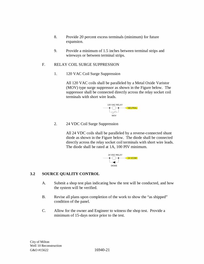
City of MiltonWell 10 ReconstructionG&O #15622 16940-21
8. Provide 20 percent excess terminals (minimum) for futureexpansion.
9. Provide a minimum of 1.5 inches between terminal strips andwireways or between terminal strips.
F. RELAY COIL SURGE SUPPRESSION
1. 120 VAC Coil Surge Suppression
All 120 VAC coils shall be paralleled by a Metal Oxide Varistor(MOV) type surge suppressor as shown in the Figure below. Thesuppressor shall be connected directly across the relay socket coilterminals with short wire leads.
NEUTRAL120 VAC RELAY
MOV
2. 24 VDC Coil Surge Suppression
All 24 VDC coils shall be paralleled by a reverse-connected shuntdiode as shown in the Figure below. The diode shall be connecteddirectly across the relay socket coil terminals with short wire leads.The diode shall be rated at 1A, 100 PIV minimum.
24 VCOM24 VDC RELAY
DIODE
3.2 SOURCE QUALITY CONTROL
A. Submit a shop test plan indicating how the test will be conducted, and howthe system will be verified.
B. Revise all plans upon completion of the work to show the “as shipped”condition of the panel.
C. Allow for the owner and Engineer to witness the shop test. Provide aminimum of 15-days notice prior to the test.
City of MiltonWell 10 ReconstructionG&O #15622 16940-22
D. Provide a shop test after factory completion and prior to shipment.
1. Test Documentation
a. Provide a testing procedure and submit to the Engineer atleast 1 week prior to the shop test.
b. Document all required corrections, even those that may beremedied during the shop test.
c. Issue a copy of the test procedures and necessarycorrections to the General Contractor and the Engineer.
d. Make all necessary corrections before shipping any panels,equipment, or devices to the job site.
e. Issue a final signed document verifying that each correctionhas been made.
2. Motor Starter Test
a. Demonstrate the complete operation of all motor starters.Connect a portable motor to each starter and operate themotor in HAND, OFF, and AUTO modes. Demonstratethe proper operation of all motor safety interlocks.
b. Preprogram all motor starter Human Interface Modules(HIMs) for compliance with motor manufacturer’sprotection criteria and compliance with the designengineer’s control requirements.
3. Other Tests
a. Provide normal operating voltage to all equipment.Demonstrate the operation of all equipment while underpower.
b. The entire assembled panel shall be tested to be free fromgrounds and shorts.
c. Controllers, circuits and interlocks shall be rung out andtested to assure that they function correctly before the panelis shipped.

City of MiltonWell 10 ReconstructionG&O #15622 16940-23
3.3 INSTALLATION
A. Install freestanding panels on concrete housekeeping pads.
B. Anchor panels rigidly in place with approved anchorage devices. Ifmounting details are shown on the Plans, then these methods shall be used.
*** END OF SECTION ***

PART 5
WAGE RATES

State of WashingtonDepartment of Labor & Industries
Prevailing Wage Section - Telephone 360-902-5335PO Box 44540, Olympia, WA 98504-4540
Washington State Prevailing WageThe PREVAILING WAGES listed here include both the hourly wage rate and the hourly rate of
fringe benefits. On public works projects, worker's wage and benefit rates must add to not lessthan this total. A brief description of overtime calculation requirements are provided on the
Benefit Code Key.
Journey Level Prevailing Wage Rates for the Effective Date: 05/02/2018
County Trade Job Classification Wage Holiday Overtime NotePierce Asbestos Abatement Workers Journey Level $46.57 5D 1H
Pierce Boilermakers Journey Level $66.54 5N 1C
Pierce Brick Mason Journey Level $55.82 5A 1M
Pierce Brick Mason Pointer-Caulker-Cleaner $55.82 5A 1M
Pierce Building Service Employees Janitor $11.50 1
Pierce Building Service Employees Shampooer $11.50 1
Pierce Building Service Employees Waxer $11.50 1
Pierce Building Service Employees Window Cleaner $13.22 1
Pierce Cabinet Makers (In Shop) Journey Level $28.36 1
Pierce Carpenters Acoustical Worker $57.18 5D 4C
Pierce Carpenters Bridge, Dock And WharfCarpenters
$57.18 5D 4C
Pierce Carpenters Carpenter $57.18 5D 4C
Pierce Carpenters Carpenters on Stationary Tools $57.31 5D 4C
Pierce Carpenters Creosoted Material $57.28 5D 4C
Pierce Carpenters Floor Finisher $57.18 5D 4C
Pierce Carpenters Floor Layer $57.18 5D 4C
Pierce Carpenters Scaffold Erector $57.18 5D 4C
Pierce Cement Masons Journey Level $57.21 7A 1M
Pierce Divers & Tenders Bell/Vehicle or SubmersibleOperator (Not Under Pressure)
$110.54 5D 4C
Pierce Divers & Tenders Dive Supervisor/Master $72.97 5D 4C
Pierce Divers & Tenders Diver $110.54 5D 4C 8V
Pierce Divers & Tenders Diver On Standby $67.97 5D 4C
Pierce Divers & Tenders Diver Tender $61.65 5D 4C
Pierce Divers & Tenders Manifold Operator $61.65 5D 4C
Pierce Divers & Tenders Manifold Operator Mixed Gas $66.65 5D 4C
Pierce Divers & Tenders Remote Operated VehicleOperator/Technician
$61.65 5D 4C
https://fortress.wa.gov/lni/wagelookup/prvWagelookup.aspx
1 of 17 4/17/2018, 10:50 AM

Pierce Divers & Tenders Remote Operated VehicleTender
$57.43 5A 4C
Pierce Dredge Workers Assistant Engineer $56.44 5D 3F
Pierce Dredge Workers Assistant Mate (Deckhand) $56.00 5D 3F
Pierce Dredge Workers Boatmen $56.44 5D 3F
Pierce Dredge Workers Engineer Welder $57.51 5D 3F
Pierce Dredge Workers Leverman, Hydraulic $58.67 5D 3F
Pierce Dredge Workers Mates $56.44 5D 3F
Pierce Dredge Workers Oiler $56.00 5D 3F
Pierce Drywall Applicator Journey Level $56.78 5D 1H
Pierce Drywall Tapers Journey Level $57.43 5P 1E
Pierce Electrical Fixture MaintenanceWorkers
Journey Level $17.76 1
Pierce Electricians - Inside Cable Splicer $68.47 5C 1G
Pierce Electricians - Inside Journey Level $64.26 5C 1G
Pierce Electricians - Inside Lead Covered Cable Splicer $72.67 5C 1G
Pierce Electricians - Inside Welder $68.47 5C 1G
Pierce Electricians - Motor Shop Craftsman $15.37 1
Pierce Electricians - Motor Shop Journey Level $14.69 1
Pierce Electricians - PowerlineConstruction
Cable Splicer $79.43 5A 4D
Pierce Electricians - PowerlineConstruction
Certified Line Welder $69.75 5A 4D
Pierce Electricians - PowerlineConstruction
Groundperson $46.28 5A 4D
Pierce Electricians - PowerlineConstruction
Heavy Line Equipment Operator $69.75 5A 4D
Pierce Electricians - PowerlineConstruction
Journey Level Lineperson $69.75 5A 4D
Pierce Electricians - PowerlineConstruction
Line Equipment Operator $59.01 5A 4D
Pierce Electricians - PowerlineConstruction
Meter Installer $46.28 5A 4D 8W
Pierce Electricians - PowerlineConstruction
Pole Sprayer $69.75 5A 4D
Pierce Electricians - PowerlineConstruction
Powderperson $52.20 5A 4D
Pierce Electronic Technicians Journey Level $32.39 1
Pierce Elevator Constructors Mechanic $91.24 7D 4A
Pierce Elevator Constructors Mechanic In Charge $98.51 7D 4A
Pierce Fabricated Precast ConcreteProducts
Journey Level - In-Factory WorkOnly
$11.50 1
Pierce Fence Erectors Fence Erector $22.56 1
Pierce Flaggers Journey Level $39.48 7A 3I
Pierce Glaziers Journey Level $61.81 7L 1Y
Pierce Heat & Frost Insulators AndAsbestos Workers
Journeyman $67.93 5J 4H
Pierce Heating Equipment Mechanics Journey Level $78.17 7F 1E
Pierce Hod Carriers & Mason Tenders Journey Level $48.02 7A 3I
https://fortress.wa.gov/lni/wagelookup/prvWagelookup.aspx
2 of 17 4/17/2018, 10:50 AM

Pierce Industrial Power VacuumCleaner
Journey Level $11.50 1
Pierce Inland Boatmen Boat Operator $61.41 5B 1K
Pierce Inland Boatmen Cook $56.48 5B 1K
Pierce Inland Boatmen Deckhand $57.48 5B 1K
Pierce Inland Boatmen Deckhand Engineer $58.81 5B 1K
Pierce Inland Boatmen Launch Operator $58.89 5B 1K
Pierce Inland Boatmen Mate $57.31 5B 1K
Pierce Inspection/Cleaning/Sealing OfSewer & Water Systems ByRemote Control
Cleaner Operator, FoamerOperator
$11.50 1
Pierce Inspection/Cleaning/Sealing OfSewer & Water Systems ByRemote Control
Grout Truck Operator $11.50 1
Pierce Inspection/Cleaning/Sealing OfSewer & Water Systems ByRemote Control
Head Operator $12.78 1
Pierce Inspection/Cleaning/Sealing OfSewer & Water Systems ByRemote Control
Technician $11.50 1
Pierce Inspection/Cleaning/Sealing OfSewer & Water Systems ByRemote Control
Tv Truck Operator $11.50 1
Pierce Insulation Applicators Journey Level $57.18 5D 4C
Pierce Ironworkers Journeyman $67.88 7N 1O
Pierce Laborers Air, Gas Or Electric VibratingScreed
$46.57 7A 3I
Pierce Laborers Airtrac Drill Operator $48.02 7A 3I
Pierce Laborers Ballast Regular Machine $46.57 7A 3I
Pierce Laborers Batch Weighman $39.48 7A 3I
Pierce Laborers Brick Pavers $46.57 7A 3I
Pierce Laborers Brush Cutter $46.57 7A 3I
Pierce Laborers Brush Hog Feeder $46.57 7A 3I
Pierce Laborers Burner $46.57 7A 3I
Pierce Laborers Caisson Worker $48.02 7A 3I
Pierce Laborers Carpenter Tender $46.57 7A 3I
Pierce Laborers Caulker $46.57 7A 3I
Pierce Laborers Cement Dumper-paving $47.44 7A 3I
Pierce Laborers Cement Finisher Tender $46.57 7A 3I
Pierce Laborers Change House Or Dry Shack $46.57 7A 3I
Pierce Laborers Chipping Gun (under 30 Lbs.) $46.57 7A 3I
Pierce Laborers Chipping Gun(30 Lbs. And Over) $47.44 7A 3I
Pierce Laborers Choker Setter $46.57 7A 3I
Pierce Laborers Chuck Tender $46.57 7A 3I
Pierce Laborers Clary Power Spreader $47.44 7A 3I
Pierce Laborers Clean-up Laborer $46.57 7A 3I
Pierce Laborers Concrete Dumper/chuteOperator
$47.44 7A 3I
Pierce Laborers Concrete Form Stripper $46.57 7A 3I
https://fortress.wa.gov/lni/wagelookup/prvWagelookup.aspx
3 of 17 4/17/2018, 10:50 AM
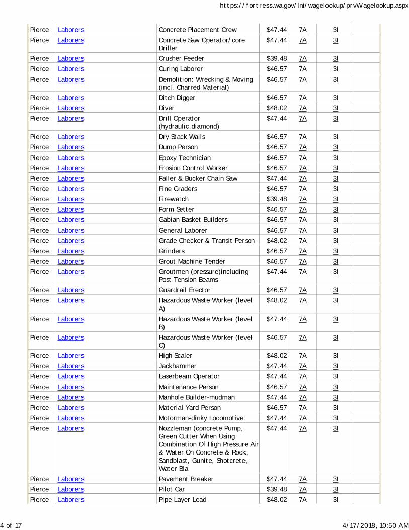
Pierce Laborers Concrete Placement Crew $47.44 7A 3I
Pierce Laborers Concrete Saw Operator/coreDriller
$47.44 7A 3I
Pierce Laborers Crusher Feeder $39.48 7A 3I
Pierce Laborers Curing Laborer $46.57 7A 3I
Pierce Laborers Demolition: Wrecking & Moving(incl. Charred Material)
$46.57 7A 3I
Pierce Laborers Ditch Digger $46.57 7A 3I
Pierce Laborers Diver $48.02 7A 3I
Pierce Laborers Drill Operator(hydraulic,diamond)
$47.44 7A 3I
Pierce Laborers Dry Stack Walls $46.57 7A 3I
Pierce Laborers Dump Person $46.57 7A 3I
Pierce Laborers Epoxy Technician $46.57 7A 3I
Pierce Laborers Erosion Control Worker $46.57 7A 3I
Pierce Laborers Faller & Bucker Chain Saw $47.44 7A 3I
Pierce Laborers Fine Graders $46.57 7A 3I
Pierce Laborers Firewatch $39.48 7A 3I
Pierce Laborers Form Setter $46.57 7A 3I
Pierce Laborers Gabian Basket Builders $46.57 7A 3I
Pierce Laborers General Laborer $46.57 7A 3I
Pierce Laborers Grade Checker & Transit Person $48.02 7A 3I
Pierce Laborers Grinders $46.57 7A 3I
Pierce Laborers Grout Machine Tender $46.57 7A 3I
Pierce Laborers Groutmen (pressure)includingPost Tension Beams
$47.44 7A 3I
Pierce Laborers Guardrail Erector $46.57 7A 3I
Pierce Laborers Hazardous Waste Worker (levelA)
$48.02 7A 3I
Pierce Laborers Hazardous Waste Worker (levelB)
$47.44 7A 3I
Pierce Laborers Hazardous Waste Worker (levelC)
$46.57 7A 3I
Pierce Laborers High Scaler $48.02 7A 3I
Pierce Laborers Jackhammer $47.44 7A 3I
Pierce Laborers Laserbeam Operator $47.44 7A 3I
Pierce Laborers Maintenance Person $46.57 7A 3I
Pierce Laborers Manhole Builder-mudman $47.44 7A 3I
Pierce Laborers Material Yard Person $46.57 7A 3I
Pierce Laborers Motorman-dinky Locomotive $47.44 7A 3I
Pierce Laborers Nozzleman (concrete Pump,Green Cutter When UsingCombination Of High Pressure Air& Water On Concrete & Rock,Sandblast, Gunite, Shotcrete,Water Bla
$47.44 7A 3I
Pierce Laborers Pavement Breaker $47.44 7A 3I
Pierce Laborers Pilot Car $39.48 7A 3I
Pierce Laborers Pipe Layer Lead $48.02 7A 3I
https://fortress.wa.gov/lni/wagelookup/prvWagelookup.aspx
4 of 17 4/17/2018, 10:50 AM

Pierce Laborers Pipe Layer/tailor $47.44 7A 3I
Pierce Laborers Pipe Pot Tender $47.44 7A 3I
Pierce Laborers Pipe Reliner $47.44 7A 3I
Pierce Laborers Pipe Wrapper $47.44 7A 3I
Pierce Laborers Pot Tender $46.57 7A 3I
Pierce Laborers Powderman $48.02 7A 3I
Pierce Laborers Powderman's Helper $46.57 7A 3I
Pierce Laborers Power Jacks $47.44 7A 3I
Pierce Laborers Railroad Spike Puller - Power $47.44 7A 3I
Pierce Laborers Raker - Asphalt $48.02 7A 3I
Pierce Laborers Re-timberman $48.02 7A 3I
Pierce Laborers Remote Equipment Operator $47.44 7A 3I
Pierce Laborers Rigger/signal Person $47.44 7A 3I
Pierce Laborers Rip Rap Person $46.57 7A 3I
Pierce Laborers Rivet Buster $47.44 7A 3I
Pierce Laborers Rodder $47.44 7A 3I
Pierce Laborers Scaffold Erector $46.57 7A 3I
Pierce Laborers Scale Person $46.57 7A 3I
Pierce Laborers Sloper (over 20") $47.44 7A 3I
Pierce Laborers Sloper Sprayer $46.57 7A 3I
Pierce Laborers Spreader (concrete) $47.44 7A 3I
Pierce Laborers Stake Hopper $46.57 7A 3I
Pierce Laborers Stock Piler $46.57 7A 3I
Pierce Laborers Tamper & Similar Electric, Air &Gas Operated Tools
$47.44 7A 3I
Pierce Laborers Tamper (multiple & Self-propelled)
$47.44 7A 3I
Pierce Laborers Timber Person - Sewer (lagger,Shorer & Cribber)
$47.44 7A 3I
Pierce Laborers Toolroom Person (at Jobsite) $46.57 7A 3I
Pierce Laborers Topper $46.57 7A 3I
Pierce Laborers Track Laborer $46.57 7A 3I
Pierce Laborers Track Liner (power) $47.44 7A 3I
Pierce Laborers Traffic Control Laborer $42.22 7A 3I 8R
Pierce Laborers Traffic Control Supervisor $42.22 7A 3I 8R
Pierce Laborers Truck Spotter $46.57 7A 3I
Pierce Laborers Tugger Operator $47.44 7A 3I
Pierce Laborers Tunnel Work-Compressed AirWorker 0-30 psi
$92.60 7A 3I 8Q
Pierce Laborers Tunnel Work-Compressed AirWorker 30.01-44.00 psi
$97.63 7A 3I 8Q
Pierce Laborers Tunnel Work-Compressed AirWorker 44.01-54.00 psi
$101.31 7A 3I 8Q
Pierce Laborers Tunnel Work-Compressed AirWorker 54.01-60.00 psi
$107.01 7A 3I 8Q
Pierce Laborers Tunnel Work-Compressed AirWorker 60.01-64.00 psi
$109.13 7A 3I 8Q
https://fortress.wa.gov/lni/wagelookup/prvWagelookup.aspx
5 of 17 4/17/2018, 10:50 AM
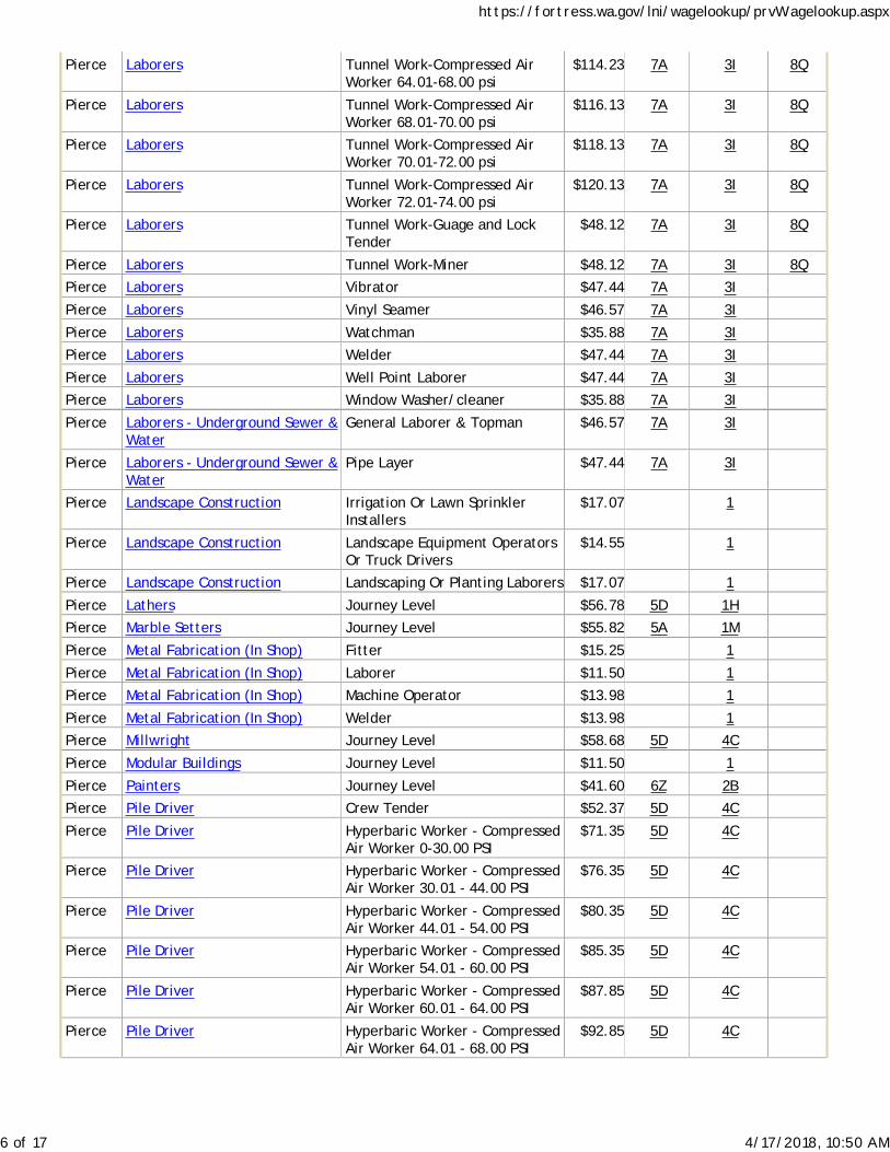
Pierce Laborers Tunnel Work-Compressed AirWorker 64.01-68.00 psi
$114.23 7A 3I 8Q
Pierce Laborers Tunnel Work-Compressed AirWorker 68.01-70.00 psi
$116.13 7A 3I 8Q
Pierce Laborers Tunnel Work-Compressed AirWorker 70.01-72.00 psi
$118.13 7A 3I 8Q
Pierce Laborers Tunnel Work-Compressed AirWorker 72.01-74.00 psi
$120.13 7A 3I 8Q
Pierce Laborers Tunnel Work-Guage and LockTender
$48.12 7A 3I 8Q
Pierce Laborers Tunnel Work-Miner $48.12 7A 3I 8Q
Pierce Laborers Vibrator $47.44 7A 3I
Pierce Laborers Vinyl Seamer $46.57 7A 3I
Pierce Laborers Watchman $35.88 7A 3I
Pierce Laborers Welder $47.44 7A 3I
Pierce Laborers Well Point Laborer $47.44 7A 3I
Pierce Laborers Window Washer/cleaner $35.88 7A 3I
Pierce Laborers - Underground Sewer &Water
General Laborer & Topman $46.57 7A 3I
Pierce Laborers - Underground Sewer &Water
Pipe Layer $47.44 7A 3I
Pierce Landscape Construction Irrigation Or Lawn SprinklerInstallers
$17.07 1
Pierce Landscape Construction Landscape Equipment OperatorsOr Truck Drivers
$14.55 1
Pierce Landscape Construction Landscaping Or Planting Laborers $17.07 1
Pierce Lathers Journey Level $56.78 5D 1H
Pierce Marble Setters Journey Level $55.82 5A 1M
Pierce Metal Fabrication (In Shop) Fitter $15.25 1
Pierce Metal Fabrication (In Shop) Laborer $11.50 1
Pierce Metal Fabrication (In Shop) Machine Operator $13.98 1
Pierce Metal Fabrication (In Shop) Welder $13.98 1
Pierce Millwright Journey Level $58.68 5D 4C
Pierce Modular Buildings Journey Level $11.50 1
Pierce Painters Journey Level $41.60 6Z 2B
Pierce Pile Driver Crew Tender $52.37 5D 4C
Pierce Pile Driver Hyperbaric Worker - CompressedAir Worker 0-30.00 PSI
$71.35 5D 4C
Pierce Pile Driver Hyperbaric Worker - CompressedAir Worker 30.01 - 44.00 PSI
$76.35 5D 4C
Pierce Pile Driver Hyperbaric Worker - CompressedAir Worker 44.01 - 54.00 PSI
$80.35 5D 4C
Pierce Pile Driver Hyperbaric Worker - CompressedAir Worker 54.01 - 60.00 PSI
$85.35 5D 4C
Pierce Pile Driver Hyperbaric Worker - CompressedAir Worker 60.01 - 64.00 PSI
$87.85 5D 4C
Pierce Pile Driver Hyperbaric Worker - CompressedAir Worker 64.01 - 68.00 PSI
$92.85 5D 4C
https://fortress.wa.gov/lni/wagelookup/prvWagelookup.aspx
6 of 17 4/17/2018, 10:50 AM

Pierce Pile Driver Hyperbaric Worker - CompressedAir Worker 68.01 - 70.00 PSI
$94.85 5D 4C
Pierce Pile Driver Hyperbaric Worker - CompressedAir Worker 70.01 - 72.00 PSI
$96.85 5D 4C
Pierce Pile Driver Hyperbaric Worker - CompressedAir Worker 72.01 - 74.00 PSI
$98.85 5D 4C
Pierce Pile Driver Journey Level $57.43 5D 4C
Pierce Plasterers Journey Level $54.89 7Q 1R
Pierce Playground & Park EquipmentInstallers
Journey Level $11.50 1
Pierce Plumbers & Pipefitters Journey Level $67.47 5A 1G
Pierce Power Equipment Operators Asphalt Plant Operator $60.49 7A 3C 8P
Pierce Power Equipment Operators Assistant Engineers $56.90 7A 3C 8P
Pierce Power Equipment Operators Barrier Machine (zipper) $59.96 7A 3C 8P
Pierce Power Equipment Operators Batch Plant Operator: Concrete $59.96 7A 3C 8P
Pierce Power Equipment Operators Bobcat $56.90 7A 3C 8P
Pierce Power Equipment Operators Brokk - Remote DemolitionEquipment
$56.90 7A 3C 8P
Pierce Power Equipment Operators Brooms $56.90 7A 3C 8P
Pierce Power Equipment Operators Bump Cutter $59.96 7A 3C 8P
Pierce Power Equipment Operators Cableways $60.49 7A 3C 8P
Pierce Power Equipment Operators Chipper $59.96 7A 3C 8P
Pierce Power Equipment Operators Compressor $56.90 7A 3C 8P
Pierce Power Equipment Operators Concrete Pump: Truck MountWith Boom Attachment Over42m
$60.49 7A 3C 8P
Pierce Power Equipment Operators Concrete Finish Machine -laserScreed
$56.90 7A 3C 8P
Pierce Power Equipment Operators Concrete Pump - Mounted OrTrailer High Pressure Line Pump,Pump High Pressure
$59.49 7A 3C 8P
Pierce Power Equipment Operators Concrete Pump: Truck MountWith Boom Attachment Up To42m
$59.96 7A 3C 8P
Pierce Power Equipment Operators Conveyors $59.49 7A 3C 8P
Pierce Power Equipment Operators Cranes, 100 Tons - 199 Tons, Or150 Ft Of Boom (including JibWith Attachments)
$61.10 7A 3C 8P
Pierce Power Equipment Operators Cranes: 20 Tons Through 44 TonsWith Attachments
$59.96 7A 3C 8P
Pierce Power Equipment Operators Cranes: 200 tons to 299 tons, or250' of boom (including jib withattachments)
$61.72 7A 3C 8P
Pierce Power Equipment Operators Cranes: 300 tons and over, or300' of boom (including jib withattachments)
$62.33 7A 3C 8P
Pierce Power Equipment Operators Cranes: 45 Tons Through 99Tons, Under 150' Of Boom(including Jib With Attachments)
$60.49 7A 3C 8P
Pierce Power Equipment Operators Cranes: A-frame - 10 Tons AndUnder
$56.90 7A 3C 8P
https://fortress.wa.gov/lni/wagelookup/prvWagelookup.aspx
7 of 17 4/17/2018, 10:50 AM

Pierce Power Equipment Operators Cranes: Friction 200 tons andover. Tower Cranes: over 250' inheight from base to boom.
$62.33 7A 3C 8P
Pierce Power Equipment Operators Cranes: Friction cranes through199 tons
$61.72 7A 3C 8P
Pierce Power Equipment Operators Cranes: Through 19 Tons WithAttachments A-frame Over 10Tons
$59.49 7A 3C 8P
Pierce Power Equipment Operators Crusher $59.96 7A 3C 8P
Pierce Power Equipment Operators Deck Engineer/deck Winches(power)
$59.96 7A 3C 8P
Pierce Power Equipment Operators Derricks, On Building Work $60.49 7A 3C 8P
Pierce Power Equipment Operators Dozers D-9 & Under $59.49 7A 3C 8P
Pierce Power Equipment Operators Drill Oilers: Auger Type, TruckOr Crane Mount
$59.49 7A 3C 8P
Pierce Power Equipment Operators Drilling Machine $61.10 7A 3C 8P
Pierce Power Equipment Operators Elevator And Man-lift:Permanent And Shaft Type
$56.90 7A 3C 8P
Pierce Power Equipment Operators Finishing Machine, Bidwell AndGamaco & Similar Equipment
$59.96 7A 3C 8P
Pierce Power Equipment Operators Forklift: 3000 Lbs And Over WithAttachments
$59.49 7A 3C 8P
Pierce Power Equipment Operators Forklifts: Under 3000 Lbs. WithAttachments
$56.90 7A 3C 8P
Pierce Power Equipment Operators Grade Engineer: UsingBlueprints, Cut Sheets,etc.
$59.96 7A 3C 8P
Pierce Power Equipment Operators Gradechecker/stakeman $56.90 7A 3C 8P
Pierce Power Equipment Operators Guardrail punch/Auger $59.96 7A 3C 8P
Pierce Power Equipment Operators Hard Tail End Dump ArticulatingOff- Road Equipment 45 Yards. &Over
$60.49 7A 3C 8P
Pierce Power Equipment Operators Hard Tail End Dump ArticulatingOff-road Equipment Under 45Yards
$59.96 7A 3C 8P
Pierce Power Equipment Operators Horizontal/directional DrillLocator
$59.49 7A 3C 8P
Pierce Power Equipment Operators Horizontal/directional DrillOperator
$59.96 7A 3C 8P
Pierce Power Equipment Operators Hydralifts/Boom Trucks Over 10Tons
$59.49 7A 3C 8P
Pierce Power Equipment Operators Hydralifts/boom Trucks, 10 TonsAnd Under
$56.90 7A 3C 8P
Pierce Power Equipment Operators Loader, Overhead 8 Yards. &Over
$61.10 7A 3C 8P
Pierce Power Equipment Operators Loader, Overhead, 6 Yards. ButNot Including 8 Yards
$60.49 7A 3C 8P
Pierce Power Equipment Operators Loaders, Overhead Under 6Yards
$59.96 7A 3C 8P
Pierce Power Equipment Operators Loaders, Plant Feed $59.96 7A 3C 8P
Pierce Power Equipment Operators Loaders: Elevating Type Belt $59.49 7A 3C 8P
Pierce Power Equipment Operators Locomotives, All $59.96 7A 3C 8P
https://fortress.wa.gov/lni/wagelookup/prvWagelookup.aspx
8 of 17 4/17/2018, 10:50 AM
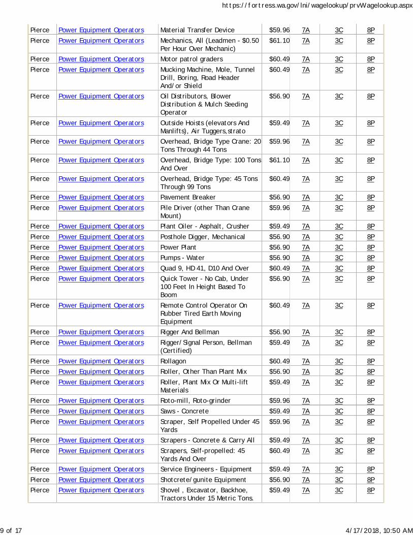
Pierce Power Equipment Operators Material Transfer Device $59.96 7A 3C 8P
Pierce Power Equipment Operators Mechanics, All (Leadmen - $0.50Per Hour Over Mechanic)
$61.10 7A 3C 8P
Pierce Power Equipment Operators Motor patrol graders $60.49 7A 3C 8P
Pierce Power Equipment Operators Mucking Machine, Mole, TunnelDrill, Boring, Road HeaderAnd/or Shield
$60.49 7A 3C 8P
Pierce Power Equipment Operators Oil Distributors, BlowerDistribution & Mulch SeedingOperator
$56.90 7A 3C 8P
Pierce Power Equipment Operators Outside Hoists (elevators AndManlifts), Air Tuggers,strato
$59.49 7A 3C 8P
Pierce Power Equipment Operators Overhead, Bridge Type Crane: 20Tons Through 44 Tons
$59.96 7A 3C 8P
Pierce Power Equipment Operators Overhead, Bridge Type: 100 TonsAnd Over
$61.10 7A 3C 8P
Pierce Power Equipment Operators Overhead, Bridge Type: 45 TonsThrough 99 Tons
$60.49 7A 3C 8P
Pierce Power Equipment Operators Pavement Breaker $56.90 7A 3C 8P
Pierce Power Equipment Operators Pile Driver (other Than CraneMount)
$59.96 7A 3C 8P
Pierce Power Equipment Operators Plant Oiler - Asphalt, Crusher $59.49 7A 3C 8P
Pierce Power Equipment Operators Posthole Digger, Mechanical $56.90 7A 3C 8P
Pierce Power Equipment Operators Power Plant $56.90 7A 3C 8P
Pierce Power Equipment Operators Pumps - Water $56.90 7A 3C 8P
Pierce Power Equipment Operators Quad 9, HD 41, D10 And Over $60.49 7A 3C 8P
Pierce Power Equipment Operators Quick Tower - No Cab, Under100 Feet In Height Based ToBoom
$56.90 7A 3C 8P
Pierce Power Equipment Operators Remote Control Operator OnRubber Tired Earth MovingEquipment
$60.49 7A 3C 8P
Pierce Power Equipment Operators Rigger And Bellman $56.90 7A 3C 8P
Pierce Power Equipment Operators Rigger/Signal Person, Bellman(Certified)
$59.49 7A 3C 8P
Pierce Power Equipment Operators Rollagon $60.49 7A 3C 8P
Pierce Power Equipment Operators Roller, Other Than Plant Mix $56.90 7A 3C 8P
Pierce Power Equipment Operators Roller, Plant Mix Or Multi-liftMaterials
$59.49 7A 3C 8P
Pierce Power Equipment Operators Roto-mill, Roto-grinder $59.96 7A 3C 8P
Pierce Power Equipment Operators Saws - Concrete $59.49 7A 3C 8P
Pierce Power Equipment Operators Scraper, Self Propelled Under 45Yards
$59.96 7A 3C 8P
Pierce Power Equipment Operators Scrapers - Concrete & Carry All $59.49 7A 3C 8P
Pierce Power Equipment Operators Scrapers, Self-propelled: 45Yards And Over
$60.49 7A 3C 8P
Pierce Power Equipment Operators Service Engineers - Equipment $59.49 7A 3C 8P
Pierce Power Equipment Operators Shotcrete/gunite Equipment $56.90 7A 3C 8P
Pierce Power Equipment Operators Shovel , Excavator, Backhoe,Tractors Under 15 Metric Tons.
$59.49 7A 3C 8P
https://fortress.wa.gov/lni/wagelookup/prvWagelookup.aspx
9 of 17 4/17/2018, 10:50 AM

Pierce Power Equipment Operators Shovel, Excavator, Backhoe:Over 30 Metric Tons To 50 MetricTons
$60.49 7A 3C 8P
Pierce Power Equipment Operators Shovel, Excavator, Backhoes,Tractors: 15 To 30 Metric Tons
$59.96 7A 3C 8P
Pierce Power Equipment Operators Shovel, Excavator, Backhoes:Over 50 Metric Tons To 90 MetricTons
$61.10 7A 3C 8P
Pierce Power Equipment Operators Shovel, Excavator, Backhoes:Over 90 Metric Tons
$61.72 7A 3C 8P
Pierce Power Equipment Operators Slipform Pavers $60.49 7A 3C 8P
Pierce Power Equipment Operators Spreader, Topsider & Screedman $60.49 7A 3C 8P
Pierce Power Equipment Operators Subgrader Trimmer $59.96 7A 3C 8P
Pierce Power Equipment Operators Tower Bucket Elevators $59.49 7A 3C 8P
Pierce Power Equipment Operators Tower crane over 175' through250' in height, base to boom
$61.72 7A 3C 8P
Pierce Power Equipment Operators Tower Crane Up: To 175' InHeight, Base To Boom
$61.10 7A 3C 8P
Pierce Power Equipment Operators Transporters, All Track Or TruckType
$60.49 7A 3C 8P
Pierce Power Equipment Operators Trenching Machines $59.49 7A 3C 8P
Pierce Power Equipment Operators Truck Crane Oiler/driver - 100Tons And Over
$59.96 7A 3C 8P
Pierce Power Equipment Operators Truck Crane Oiler/driver Under100 Tons
$59.49 7A 3C 8P
Pierce Power Equipment Operators Truck Mount Portable Conveyor $59.96 7A 3C 8P
Pierce Power Equipment Operators Welder $60.49 7A 3C 8P
Pierce Power Equipment Operators Wheel Tractors, Farmall Type $56.90 7A 3C 8P
Pierce Power Equipment Operators Yo Yo Pay Dozer $59.96 7A 3C 8P
Pierce Power Equipment Operators-Underground Sewer & Water
Asphalt Plant Operator $60.49 7A 3C 8P
Pierce Power Equipment Operators-Underground Sewer & Water
Assistant Engineers $56.90 7A 3C 8P
Pierce Power Equipment Operators-Underground Sewer & Water
Barrier Machine (zipper) $59.96 7A 3C 8P
Pierce Power Equipment Operators-Underground Sewer & Water
Batch Plant Operator: Concrete $59.96 7A 3C 8P
Pierce Power Equipment Operators-Underground Sewer & Water
Bobcat $56.90 7A 3C 8P
Pierce Power Equipment Operators-Underground Sewer & Water
Brokk - Remote DemolitionEquipment
$56.90 7A 3C 8P
Pierce Power Equipment Operators-Underground Sewer & Water
Brooms $56.90 7A 3C 8P
Pierce Power Equipment Operators-Underground Sewer & Water
Bump Cutter $59.96 7A 3C 8P
Pierce Power Equipment Operators-Underground Sewer & Water
Cableways $60.49 7A 3C 8P
Pierce Power Equipment Operators-Underground Sewer & Water
Chipper $59.96 7A 3C 8P
Pierce Power Equipment Operators-Underground Sewer & Water
Compressor $56.90 7A 3C 8P
https://fortress.wa.gov/lni/wagelookup/prvWagelookup.aspx
10 of 17 4/17/2018, 10:50 AM

Pierce Power Equipment Operators-Underground Sewer & Water
Concrete Pump: Truck MountWith Boom Attachment Over42m
$60.49 7A 3C 8P
Pierce Power Equipment Operators-Underground Sewer & Water
Concrete Finish Machine -laserScreed
$56.90 7A 3C 8P
Pierce Power Equipment Operators-Underground Sewer & Water
Concrete Pump - Mounted OrTrailer High Pressure Line Pump,Pump High Pressure
$59.49 7A 3C 8P
Pierce Power Equipment Operators-Underground Sewer & Water
Concrete Pump: Truck MountWith Boom Attachment Up To42m
$59.96 7A 3C 8P
Pierce Power Equipment Operators-Underground Sewer & Water
Conveyors $59.49 7A 3C 8P
Pierce Power Equipment Operators-Underground Sewer & Water
Cranes, 100 Tons - 199 Tons, Or150 Ft Of Boom (including JibWith Attachments)
$61.10 7A 3C 8P
Pierce Power Equipment Operators-Underground Sewer & Water
Cranes, 200 tons to 299 tons, or250' of boom (including jib withattachments)
$61.72 7A 3C 8P
Pierce Power Equipment Operators-Underground Sewer & Water
Cranes, Over 300 Tons, Or 300'Of Boom Including Jib WithAttachments
$62.33 7A 3C 8P
Pierce Power Equipment Operators-Underground Sewer & Water
Cranes: 20 Tons Through 44 TonsWith Attachments
$59.96 7A 3C 8P
Pierce Power Equipment Operators-Underground Sewer & Water
cranes: 300 tons and over, or300' of boom (including jib withattachments)
$62.33 7A 3C 8P
Pierce Power Equipment Operators-Underground Sewer & Water
Cranes: 45 Tons Through 99Tons, Under 150' Of Boom(including Jib With Attachments)
$60.49 7A 3C 8P
Pierce Power Equipment Operators-Underground Sewer & Water
Cranes: A-frame - 10 Tons AndUnder
$56.90 7A 3C 8P
Pierce Power Equipment Operators-Underground Sewer & Water
Cranes: Friction 200 tons andover. Tower Cranes: over 250' inheight from base to boom.
$62.33 7A 3C 8P
Pierce Power Equipment Operators-Underground Sewer & Water
Cranes: Friction cranes through199 tons
$61.72 7A 3C 8P
Pierce Power Equipment Operators-Underground Sewer & Water
Cranes: Through 19 Tons WithAttachments A-frame Over 10Tons
$59.49 7A 3C 8P
Pierce Power Equipment Operators-Underground Sewer & Water
Crusher $59.96 7A 3C 8P
Pierce Power Equipment Operators-Underground Sewer & Water
Deck Engineer/deck Winches(power)
$59.96 7A 3C 8P
Pierce Power Equipment Operators-Underground Sewer & Water
Derricks, On Building Work $60.49 7A 3C 8P
Pierce Power Equipment Operators-Underground Sewer & Water
Dozers D-9 & Under $59.49 7A 3C 8P
Pierce Power Equipment Operators-Underground Sewer & Water
Drill Oilers: Auger Type, TruckOr Crane Mount
$59.49 7A 3C 8P
Pierce Power Equipment Operators-Underground Sewer & Water
Drilling Machine $61.10 7A 3C 8P
https://fortress.wa.gov/lni/wagelookup/prvWagelookup.aspx
11 of 17 4/17/2018, 10:50 AM
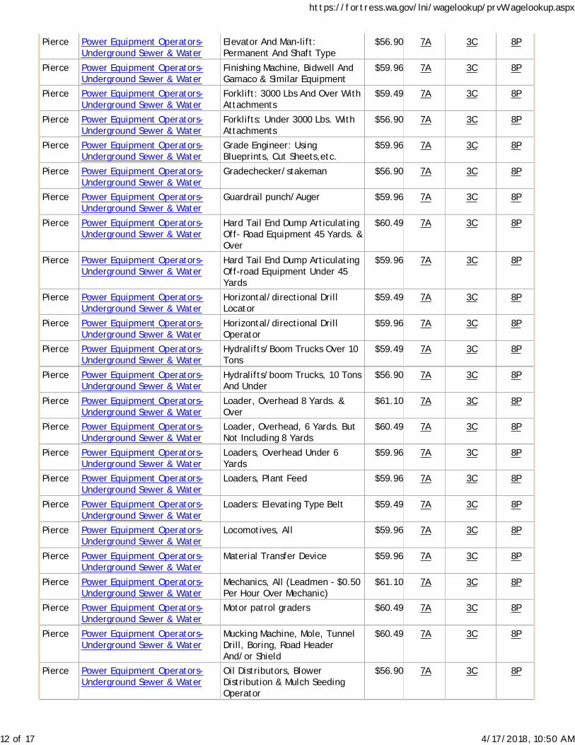
Pierce Power Equipment Operators-Underground Sewer & Water
Elevator And Man-lift:Permanent And Shaft Type
$56.90 7A 3C 8P
Pierce Power Equipment Operators-Underground Sewer & Water
Finishing Machine, Bidwell AndGamaco & Similar Equipment
$59.96 7A 3C 8P
Pierce Power Equipment Operators-Underground Sewer & Water
Forklift: 3000 Lbs And Over WithAttachments
$59.49 7A 3C 8P
Pierce Power Equipment Operators-Underground Sewer & Water
Forklifts: Under 3000 Lbs. WithAttachments
$56.90 7A 3C 8P
Pierce Power Equipment Operators-Underground Sewer & Water
Grade Engineer: UsingBlueprints, Cut Sheets,etc.
$59.96 7A 3C 8P
Pierce Power Equipment Operators-Underground Sewer & Water
Gradechecker/stakeman $56.90 7A 3C 8P
Pierce Power Equipment Operators-Underground Sewer & Water
Guardrail punch/Auger $59.96 7A 3C 8P
Pierce Power Equipment Operators-Underground Sewer & Water
Hard Tail End Dump ArticulatingOff- Road Equipment 45 Yards. &Over
$60.49 7A 3C 8P
Pierce Power Equipment Operators-Underground Sewer & Water
Hard Tail End Dump ArticulatingOff-road Equipment Under 45Yards
$59.96 7A 3C 8P
Pierce Power Equipment Operators-Underground Sewer & Water
Horizontal/directional DrillLocator
$59.49 7A 3C 8P
Pierce Power Equipment Operators-Underground Sewer & Water
Horizontal/directional DrillOperator
$59.96 7A 3C 8P
Pierce Power Equipment Operators-Underground Sewer & Water
Hydralifts/Boom Trucks Over 10Tons
$59.49 7A 3C 8P
Pierce Power Equipment Operators-Underground Sewer & Water
Hydralifts/boom Trucks, 10 TonsAnd Under
$56.90 7A 3C 8P
Pierce Power Equipment Operators-Underground Sewer & Water
Loader, Overhead 8 Yards. &Over
$61.10 7A 3C 8P
Pierce Power Equipment Operators-Underground Sewer & Water
Loader, Overhead, 6 Yards. ButNot Including 8 Yards
$60.49 7A 3C 8P
Pierce Power Equipment Operators-Underground Sewer & Water
Loaders, Overhead Under 6Yards
$59.96 7A 3C 8P
Pierce Power Equipment Operators-Underground Sewer & Water
Loaders, Plant Feed $59.96 7A 3C 8P
Pierce Power Equipment Operators-Underground Sewer & Water
Loaders: Elevating Type Belt $59.49 7A 3C 8P
Pierce Power Equipment Operators-Underground Sewer & Water
Locomotives, All $59.96 7A 3C 8P
Pierce Power Equipment Operators-Underground Sewer & Water
Material Transfer Device $59.96 7A 3C 8P
Pierce Power Equipment Operators-Underground Sewer & Water
Mechanics, All (Leadmen - $0.50Per Hour Over Mechanic)
$61.10 7A 3C 8P
Pierce Power Equipment Operators-Underground Sewer & Water
Motor patrol graders $60.49 7A 3C 8P
Pierce Power Equipment Operators-Underground Sewer & Water
Mucking Machine, Mole, TunnelDrill, Boring, Road HeaderAnd/or Shield
$60.49 7A 3C 8P
Pierce Power Equipment Operators-Underground Sewer & Water
Oil Distributors, BlowerDistribution & Mulch SeedingOperator
$56.90 7A 3C 8P
https://fortress.wa.gov/lni/wagelookup/prvWagelookup.aspx
12 of 17 4/17/2018, 10:50 AM

Pierce Power Equipment Operators-Underground Sewer & Water
Outside Hoists (elevators AndManlifts), Air Tuggers,strato
$59.49 7A 3C 8P
Pierce Power Equipment Operators-Underground Sewer & Water
Overhead, Bridge Type Crane: 20Tons Through 44 Tons
$59.96 7A 3C 8P
Pierce Power Equipment Operators-Underground Sewer & Water
Overhead, Bridge Type: 100 TonsAnd Over
$61.10 7A 3C 8P
Pierce Power Equipment Operators-Underground Sewer & Water
Overhead, Bridge Type: 45 TonsThrough 99 Tons
$60.49 7A 3C 8P
Pierce Power Equipment Operators-Underground Sewer & Water
Pavement Breaker $56.90 7A 3C 8P
Pierce Power Equipment Operators-Underground Sewer & Water
Pile Driver (other Than CraneMount)
$59.96 7A 3C 8P
Pierce Power Equipment Operators-Underground Sewer & Water
Plant Oiler - Asphalt, Crusher $59.49 7A 3C 8P
Pierce Power Equipment Operators-Underground Sewer & Water
Posthole Digger, Mechanical $56.90 7A 3C 8P
Pierce Power Equipment Operators-Underground Sewer & Water
Power Plant $56.90 7A 3C 8P
Pierce Power Equipment Operators-Underground Sewer & Water
Pumps - Water $56.90 7A 3C 8P
Pierce Power Equipment Operators-Underground Sewer & Water
Quad 9, HD 41, D10 And Over $60.49 7A 3C 8P
Pierce Power Equipment Operators-Underground Sewer & Water
Quick Tower - No Cab, Under100 Feet In Height Based ToBoom
$56.90 7A 3C 8P
Pierce Power Equipment Operators-Underground Sewer & Water
Remote Control Operator OnRubber Tired Earth MovingEquipment
$60.49 7A 3C 8P
Pierce Power Equipment Operators-Underground Sewer & Water
Rigger And Bellman $56.90 7A 3C 8P
Pierce Power Equipment Operators-Underground Sewer & Water
Rigger/Signal Person, Bellman(Certified)
$59.49 7A 3C 8P
Pierce Power Equipment Operators-Underground Sewer & Water
Rollagon $60.49 7A 3C 8P
Pierce Power Equipment Operators-Underground Sewer & Water
Roller, Other Than Plant Mix $56.90 7A 3C 8P
Pierce Power Equipment Operators-Underground Sewer & Water
Roller, Plant Mix Or Multi-liftMaterials
$59.49 7A 3C 8P
Pierce Power Equipment Operators-Underground Sewer & Water
Roto-mill, Roto-grinder $59.96 7A 3C 8P
Pierce Power Equipment Operators-Underground Sewer & Water
Saws - Concrete $59.49 7A 3C 8P
Pierce Power Equipment Operators-Underground Sewer & Water
Scraper, Self Propelled Under 45Yards
$59.96 7A 3C 8P
Pierce Power Equipment Operators-Underground Sewer & Water
Scrapers - Concrete & Carry All $59.49 7A 3C 8P
Pierce Power Equipment Operators-Underground Sewer & Water
Scrapers, Self-propelled: 45Yards And Over
$60.49 7A 3C 8P
Pierce Power Equipment Operators-Underground Sewer & Water
Service Engineers - Equipment $59.49 7A 3C 8P
Pierce Power Equipment Operators-Underground Sewer & Water
Shotcrete/gunite Equipment $56.90 7A 3C 8P
https://fortress.wa.gov/lni/wagelookup/prvWagelookup.aspx
13 of 17 4/17/2018, 10:50 AM

Pierce Power Equipment Operators-Underground Sewer & Water
Shovel , Excavator, Backhoe,Tractors Under 15 Metric Tons.
$59.49 7A 3C 8P
Pierce Power Equipment Operators-Underground Sewer & Water
Shovel, Excavator, Backhoe:Over 30 Metric Tons To 50 MetricTons
$60.49 7A 3C 8P
Pierce Power Equipment Operators-Underground Sewer & Water
Shovel, Excavator, Backhoes,Tractors: 15 To 30 Metric Tons
$59.96 7A 3C 8P
Pierce Power Equipment Operators-Underground Sewer & Water
Shovel, Excavator, Backhoes:Over 50 Metric Tons To 90 MetricTons
$61.10 7A 3C 8P
Pierce Power Equipment Operators-Underground Sewer & Water
Shovel, Excavator, Backhoes:Over 90 Metric Tons
$61.72 7A 3C 8P
Pierce Power Equipment Operators-Underground Sewer & Water
Slipform Pavers $60.49 7A 3C 8P
Pierce Power Equipment Operators-Underground Sewer & Water
Spreader, Topsider & Screedman $60.49 7A 3C 8P
Pierce Power Equipment Operators-Underground Sewer & Water
Subgrader Trimmer $59.96 7A 3C 8P
Pierce Power Equipment Operators-Underground Sewer & Water
Tower Bucket Elevators $59.49 7A 3C 8P
Pierce Power Equipment Operators-Underground Sewer & Water
Tower crane over 175' through250' in height, base to boom
$61.72 7A 3C 8P
Pierce Power Equipment Operators-Underground Sewer & Water
Tower Crane: Up To 175' InHeight, Base To Boom
$61.10 7A 3C 8P
Pierce Power Equipment Operators-Underground Sewer & Water
Transporters, All Track Or TruckType
$60.49 7A 3C 8P
Pierce Power Equipment Operators-Underground Sewer & Water
Trenching Machines $59.49 7A 3C 8P
Pierce Power Equipment Operators-Underground Sewer & Water
Truck Crane Oiler/driver - 100Tons And Over
$59.96 7A 3C 8P
Pierce Power Equipment Operators-Underground Sewer & Water
Truck Crane Oiler/driver Under100 Tons
$59.49 7A 3C 8P
Pierce Power Equipment Operators-Underground Sewer & Water
Truck Mount Portable Conveyor $59.96 7A 3C 8P
Pierce Power Equipment Operators-Underground Sewer & Water
Welder $60.49 7A 3C 8P
Pierce Power Equipment Operators-Underground Sewer & Water
Wheel Tractors, Farmall Type $56.90 7A 3C 8P
Pierce Power Equipment Operators-Underground Sewer & Water
Yo Yo Pay Dozer $59.96 7A 3C 8P
Pierce Power Line Clearance TreeTrimmers
Journey Level In Charge $50.02 5A 4A
Pierce Power Line Clearance TreeTrimmers
Spray Person $47.43 5A 4A
Pierce Power Line Clearance TreeTrimmers
Tree Equipment Operator $50.02 5A 4A
Pierce Power Line Clearance TreeTrimmers
Tree Trimmer $44.64 5A 4A
Pierce Power Line Clearance TreeTrimmers
Tree Trimmer Groundperson $33.67 5A 4A
Pierce Refrigeration & Air ConditioningMechanics
Mechanic $68.76 5A 1G
https://fortress.wa.gov/lni/wagelookup/prvWagelookup.aspx
14 of 17 4/17/2018, 10:50 AM
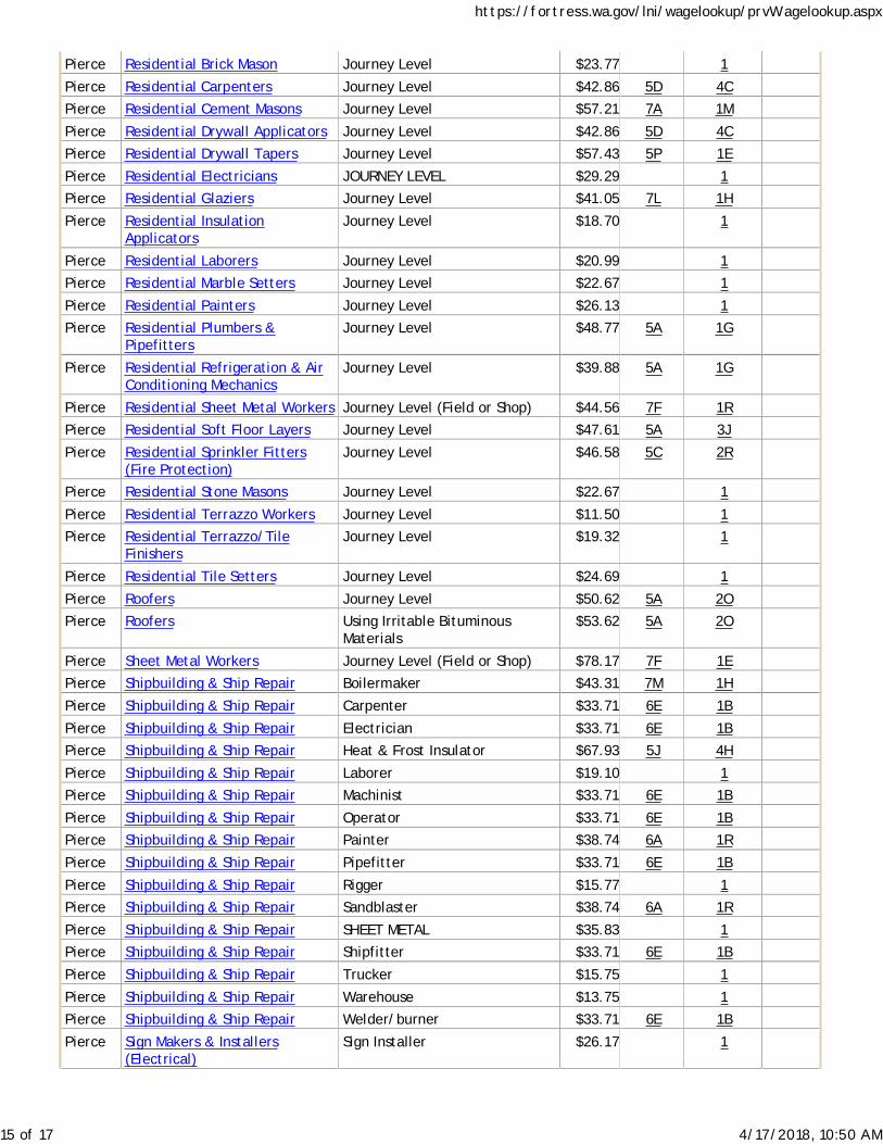
Pierce Residential Brick Mason Journey Level $23.77 1
Pierce Residential Carpenters Journey Level $42.86 5D 4C
Pierce Residential Cement Masons Journey Level $57.21 7A 1M
Pierce Residential Drywall Applicators Journey Level $42.86 5D 4C
Pierce Residential Drywall Tapers Journey Level $57.43 5P 1E
Pierce Residential Electricians JOURNEY LEVEL $29.29 1
Pierce Residential Glaziers Journey Level $41.05 7L 1H
Pierce Residential InsulationApplicators
Journey Level $18.70 1
Pierce Residential Laborers Journey Level $20.99 1
Pierce Residential Marble Setters Journey Level $22.67 1
Pierce Residential Painters Journey Level $26.13 1
Pierce Residential Plumbers &Pipefitters
Journey Level $48.77 5A 1G
Pierce Residential Refrigeration & AirConditioning Mechanics
Journey Level $39.88 5A 1G
Pierce Residential Sheet Metal Workers Journey Level (Field or Shop) $44.56 7F 1R
Pierce Residential Soft Floor Layers Journey Level $47.61 5A 3J
Pierce Residential Sprinkler Fitters(Fire Protection)
Journey Level $46.58 5C 2R
Pierce Residential Stone Masons Journey Level $22.67 1
Pierce Residential Terrazzo Workers Journey Level $11.50 1
Pierce Residential Terrazzo/TileFinishers
Journey Level $19.32 1
Pierce Residential Tile Setters Journey Level $24.69 1
Pierce Roofers Journey Level $50.62 5A 2O
Pierce Roofers Using Irritable BituminousMaterials
$53.62 5A 2O
Pierce Sheet Metal Workers Journey Level (Field or Shop) $78.17 7F 1E
Pierce Shipbuilding & Ship Repair Boilermaker $43.31 7M 1H
Pierce Shipbuilding & Ship Repair Carpenter $33.71 6E 1B
Pierce Shipbuilding & Ship Repair Electrician $33.71 6E 1B
Pierce Shipbuilding & Ship Repair Heat & Frost Insulator $67.93 5J 4H
Pierce Shipbuilding & Ship Repair Laborer $19.10 1
Pierce Shipbuilding & Ship Repair Machinist $33.71 6E 1B
Pierce Shipbuilding & Ship Repair Operator $33.71 6E 1B
Pierce Shipbuilding & Ship Repair Painter $38.74 6A 1R
Pierce Shipbuilding & Ship Repair Pipefitter $33.71 6E 1B
Pierce Shipbuilding & Ship Repair Rigger $15.77 1
Pierce Shipbuilding & Ship Repair Sandblaster $38.74 6A 1R
Pierce Shipbuilding & Ship Repair SHEET METAL $35.83 1
Pierce Shipbuilding & Ship Repair Shipfitter $33.71 6E 1B
Pierce Shipbuilding & Ship Repair Trucker $15.75 1
Pierce Shipbuilding & Ship Repair Warehouse $13.75 1
Pierce Shipbuilding & Ship Repair Welder/burner $33.71 6E 1B
Pierce Sign Makers & Installers(Electrical)
Sign Installer $26.17 1
https://fortress.wa.gov/lni/wagelookup/prvWagelookup.aspx
15 of 17 4/17/2018, 10:50 AM
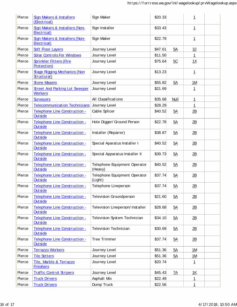
Pierce Sign Makers & Installers(Electrical)
Sign Maker $20.33 1
Pierce Sign Makers & Installers (Non-Electrical)
Sign Installer $33.43 1
Pierce Sign Makers & Installers (Non-Electrical)
Sign Maker $22.79 1
Pierce Soft Floor Layers Journey Level $47.61 5A 3J
Pierce Solar Controls For Windows Journey Level $11.50 1
Pierce Sprinkler Fitters (FireProtection)
Journey Level $75.64 5C 1X
Pierce Stage Rigging Mechanics (NonStructural)
Journey Level $13.23 1
Pierce Stone Masons Journey Level $55.82 5A 1M
Pierce Street And Parking Lot SweeperWorkers
Journey Level $21.69 1
Pierce Surveyors All Classifications $35.68 Null 1
Pierce Telecommunication Technicians Journey Level $28.29 1
Pierce Telephone Line Construction -Outside
Cable Splicer $40.52 5A 2B
Pierce Telephone Line Construction -Outside
Hole Digger/Ground Person $22.78 5A 2B
Pierce Telephone Line Construction -Outside
Installer (Repairer) $38.87 5A 2B
Pierce Telephone Line Construction -Outside
Special Aparatus Installer I $40.52 5A 2B
Pierce Telephone Line Construction -Outside
Special Apparatus Installer II $39.73 5A 2B
Pierce Telephone Line Construction -Outside
Telephone Equipment Operator(Heavy)
$40.52 5A 2B
Pierce Telephone Line Construction -Outside
Telephone Equipment Operator(Light)
$37.74 5A 2B
Pierce Telephone Line Construction -Outside
Telephone Lineperson $37.74 5A 2B
Pierce Telephone Line Construction -Outside
Television Groundperson $21.60 5A 2B
Pierce Telephone Line Construction -Outside
Television Lineperson/Installer $28.68 5A 2B
Pierce Telephone Line Construction -Outside
Television System Technician $34.10 5A 2B
Pierce Telephone Line Construction -Outside
Television Technician $30.69 5A 2B
Pierce Telephone Line Construction -Outside
Tree Trimmer $37.74 5A 2B
Pierce Terrazzo Workers Journey Level $51.36 5A 1M
Pierce Tile Setters Journey Level $51.36 5A 1M
Pierce Tile, Marble & TerrazzoFinishers
Journey Level $20.74 1
Pierce Traffic Control Stripers Journey Level $45.43 7A 1K
Pierce Truck Drivers Asphalt Mix $22.49 1
Pierce Truck Drivers Dump Truck $22.56 1
https://fortress.wa.gov/lni/wagelookup/prvWagelookup.aspx
16 of 17 4/17/2018, 10:50 AM

Pierce Truck Drivers Dump Truck And Trailer $22.56 1
Pierce Truck Drivers Other Trucks $30.20 1
Pierce Truck Drivers Transit Mixer $33.17 6I 2H
Pierce Well Drillers & Irrigation PumpInstallers
Irrigation Pump Installer $16.09 1
Pierce Well Drillers & Irrigation PumpInstallers
Oiler $15.39 1
Pierce Well Drillers & Irrigation PumpInstallers
Well Driller $18.30 1
https://fortress.wa.gov/lni/wagelookup/prvWagelookup.aspx
17 of 17 4/17/2018, 10:50 AM
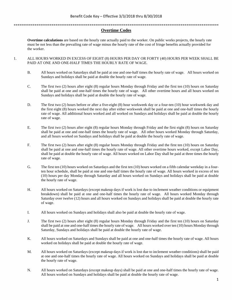
Benefit Code Key – Effective 3/3/2018 thru 8/30/2018
1
************************************************************************************************************ Overtime Codes
Overtime calculations are based on the hourly rate actually paid to the worker. On public works projects, the hourly rate must be not less than the prevailing rate of wage minus the hourly rate of the cost of fringe benefits actually provided for the worker.
1. ALL HOURS WORKED IN EXCESS OF EIGHT (8) HOURS PER DAY OR FORTY (40) HOURS PER WEEK SHALL BE
PAID AT ONE AND ONE-HALF TIMES THE HOURLY RATE OF WAGE.
B. All hours worked on Saturdays shall be paid at one and one-half times the hourly rate of wage. All hours worked on Sundays and holidays shall be paid at double the hourly rate of wage.
C. The first two (2) hours after eight (8) regular hours Monday through Friday and the first ten (10) hours on Saturday
shall be paid at one and one-half times the hourly rate of wage. All other overtime hours and all hours worked on Sundays and holidays shall be paid at double the hourly rate of wage.
D. The first two (2) hours before or after a five-eight (8) hour workweek day or a four-ten (10) hour workweek day and
the first eight (8) hours worked the next day after either workweek shall be paid at one and one-half times the hourly rate of wage. All additional hours worked and all worked on Sundays and holidays shall be paid at double the hourly rate of wage.
E. The first two (2) hours after eight (8) regular hours Monday through Friday and the first eight (8) hours on Saturday
shall be paid at one and one-half times the hourly rate of wage. All other hours worked Monday through Saturday, and all hours worked on Sundays and holidays shall be paid at double the hourly rate of wage.
F. The first two (2) hours after eight (8) regular hours Monday through Friday and the first ten (10) hours on Saturday
shall be paid at one and one-half times the hourly rate of wage. All other overtime hours worked, except Labor Day, shall be paid at double the hourly rate of wage. All hours worked on Labor Day shall be paid at three times the hourly rate of wage.
G. The first ten (10) hours worked on Saturdays and the first ten (10) hours worked on a fifth calendar weekday in a four-
ten hour schedule, shall be paid at one and one-half times the hourly rate of wage. All hours worked in excess of ten (10) hours per day Monday through Saturday and all hours worked on Sundays and holidays shall be paid at double the hourly rate of wage.
H. All hours worked on Saturdays (except makeup days if work is lost due to inclement weather conditions or equipment
breakdown) shall be paid at one and one-half times the hourly rate of wage. All hours worked Monday through Saturday over twelve (12) hours and all hours worked on Sundays and holidays shall be paid at double the hourly rate of wage.
I. All hours worked on Sundays and holidays shall also be paid at double the hourly rate of wage.
J. The first two (2) hours after eight (8) regular hours Monday through Friday and the first ten (10) hours on Saturday
shall be paid at one and one-half times the hourly rate of wage. All hours worked over ten (10) hours Monday through Saturday, Sundays and holidays shall be paid at double the hourly rate of wage.
K. All hours worked on Saturdays and Sundays shall be paid at one and one-half times the hourly rate of wage. All hours
worked on holidays shall be paid at double the hourly rate of wage. M. All hours worked on Saturdays (except makeup days if work is lost due to inclement weather conditions) shall be paid
at one and one-half times the hourly rate of wage. All hours worked on Sundays and holidays shall be paid at double the hourly rate of wage.
N. All hours worked on Saturdays (except makeup days) shall be paid at one and one-half times the hourly rate of wage.
All hours worked on Sundays and holidays shall be paid at double the hourly rate of wage.

Benefit Code Key – Effective 3/3/2018 thru 8/30/2018
2
Overtime Codes Continued
1. O. The first ten (10) hours worked on Saturday shall be paid at one and one-half times the hourly rate of wage. All hours
worked on Sundays, holidays and after twelve (12) hours, Monday through Friday and after ten (10) hours on Saturday shall be paid at double the hourly rate of wage.
P. All hours worked on Saturdays (except makeup days if circumstances warrant) and Sundays shall be paid at one and
one-half times the hourly rate of wage. All hours worked on holidays shall be paid at double the hourly rate of wage.
Q. The first two (2) hours after eight (8) regular hours Monday through Friday and up to ten (10) hours worked on Saturdays shall be paid at one and one-half times the hourly rate of wage. All hours worked in excess of ten (10) hours per day Monday through Saturday and all hours worked on Sundays and holidays (except Christmas day) shall be paid at double the hourly rate of wage. All hours worked on Christmas day shall be paid at two and one-half times the hourly rate of wage.
R. All hours worked on Sundays and holidays shall be paid at two times the hourly rate of wage. S. The first two (2) hours after eight (8) regular hours Monday through Friday and the first eight (8) hours on Saturday
shall be paid at one and one-half times the hourly rate of wage. All hours worked on holidays and all other overtime hours worked, except Labor Day, shall be paid at double the hourly rate of wage. All hours worked on Labor Day shall be paid at three times the hourly rate of wage.
U. All hours worked on Saturdays shall be paid at one and one-half times the hourly rate of wage. All hours worked on
Sundays and holidays (except Labor Day) shall be paid at two times the hourly rate of wage. All hours worked on Labor Day shall be paid at three times the hourly rate of wage.
V. All hours worked on Sundays and holidays (except Thanksgiving Day and Christmas day) shall be paid at one and
one-half times the hourly rate of wage. All hours worked on Thanksgiving Day and Christmas day shall be paid at double the hourly rate of wage.
W. All hours worked on Saturdays and Sundays (except make-up days due to conditions beyond the control of the
employer)) shall be paid at one and one-half times the hourly rate of wage. All hours worked on holidays shall be paid at double the hourly rate of wage.
X. The first four (4) hours after eight (8) regular hours Monday through Friday and the first twelve (12) hours on Saturday
shall be paid at one and one-half times the hourly rate of wage. All hours worked over twelve (12) hours Monday through Saturday, Sundays and holidays shall be paid at double the hourly rate of wage. When holiday falls on Saturday or Sunday, the day before Saturday, Friday, and the day after Sunday, Monday, shall be considered the holiday and all work performed shall be paid at double the hourly rate of wage.
Y. All hours worked outside the hours of 5:00 am and 5:00 pm (or such other hours as may be agreed upon by any
employer and the employee) and all hours worked in excess of eight (8) hours per day (10 hours per day for a 4 x 10 workweek) and on Saturdays and holidays (except labor day) shall be paid at one and one-half times the hourly rate of wage. (except for employees who are absent from work without prior approval on a scheduled workday during the workweek shall be paid at the straight-time rate until they have worked 8 hours in a day (10 in a 4 x 10 workweek) or 40 hours during that workweek.) All hours worked Monday through Saturday over twelve (12) hours and all hours worked on Sundays and Labor Day shall be paid at double the hourly rate of wage.
Z. All hours worked on Saturdays and Sundays shall be paid at one and one-half times the hourly rate of wage. All
hours worked on holidays shall be paid the straight time rate of pay in addition to holiday pay.

Benefit Code Key – Effective 3/3/2018 thru 8/30/2018
3
Overtime Codes Continued
2. ALL HOURS WORKED IN EXCESS OF EIGHT (8) HOURS PER DAY OR FORTY (40) HOURS PER WEEK SHALL BE PAID AT ONE AND ONE-HALF TIMES THE HOURLY RATE OF WAGE. B. All hours worked on holidays shall be paid at one and one-half times the hourly rate of wage.
C. All hours worked on Sundays shall be paid at one and one-half times the hourly rate of wage. All hours worked on holidays shall be paid at two times the hourly rate of wage.
F. The first eight (8) hours worked on holidays shall be paid at the straight hourly rate of wage in addition to the holiday
pay. All hours worked in excess of eight (8) hours on holidays shall be paid at double the hourly rate of wage.
G. All hours worked on Sunday shall be paid at two times the hourly rate of wage. All hours worked on paid holidays shall be paid at two and one-half times the hourly rate of wage including holiday pay.
H. All hours worked on Sunday shall be paid at two times the hourly rate of wage. All hours worked on holidays shall
be paid at one and one-half times the hourly rate of wage. O. All hours worked on Sundays and holidays shall be paid at one and one-half times the hourly rate of wage. R. All hours worked on Sundays and holidays and all hours worked over sixty (60) in one week shall be paid at double
the hourly rate of wage. U. All hours worked on Saturdays shall be paid at one and one-half times the hourly rate of wage. All hours worked
over 12 hours in a day or on Sundays and holidays shall be paid at double the hourly rate of wage. W. The first two (2) hours after eight (8) regular hours Monday through Friday and the first eight (8) hours on Saturday
shall be paid at one and one-half times the hourly rate of wage. All other hours worked Monday through Saturday, and all hours worked on Sundays and holidays shall be paid at double the hourly rate of wage. On a four-day, ten-hour weekly schedule, either Monday thru Thursday or Tuesday thru Friday schedule, all hours worked after ten shall be paid at double the hourly rate of wage. The first eight (8) hours worked on the fifth day shall be paid at one and one-half times the hourly rate of wage. All other hours worked on the fifth, sixth, and seventh days and on holidays shall be paid at double the hourly rate of wage.
3. ALL HOURS WORKED IN EXCESS OF EIGHT (8) HOURS PER DAY OR FORTY (40) HOURS PER WEEK SHALL BE PAID AT ONE AND ONE-HALF TIMES THE HOURLY RATE OF WAGE. A. Work performed in excess of eight (8) hours of straight time per day, or ten (10) hours of straight time per day when
four ten (10) hour shifts are established, or forty (40) hours of straight time per week, Monday through Friday, or outside the normal shift, and all work on Saturdays shall be paid at time and one-half the straight time rate. Hours worked over twelve hours (12) in a single shift and all work performed after 6:00 pm Saturday to 6:00 am Monday and holidays shall be paid at double the straight time rate of pay. Any shift starting between the hours of 6:00 pm and midnight shall receive an additional one dollar ($1.00) per hour for all hours worked that shift. The employer shall have the sole discretion to assign overtime work to employees. Primary consideration for overtime work shall be given to employees regularly assigned to the work to be performed on overtime situations. After an employee has worked eight (8) hours at an applicable overtime rate, all additional hours shall be at the applicable overtime rate until such time as the employee has had a break of eight (8) hours or more.
C. Work performed in excess of eight (8) hours of straight time per day, or ten (10) hours of straight time per day when
four ten (10) hour shifts are established, or forty (40) hours of straight time per week, Monday through Friday, or outside the normal shift, and all work on Saturdays shall be paid at one and one-half times the hourly rate of wage. All work performed after 6:00 pm Saturday to 5:00 am Monday and Holidays shall be paid at double the hourly rate of wage. After an employee has worked eight (8) hours at an applicable overtime rate, all additional hours shall be at the applicable overtime rate until such time as the employee has had a break of eight (8) hours or more.
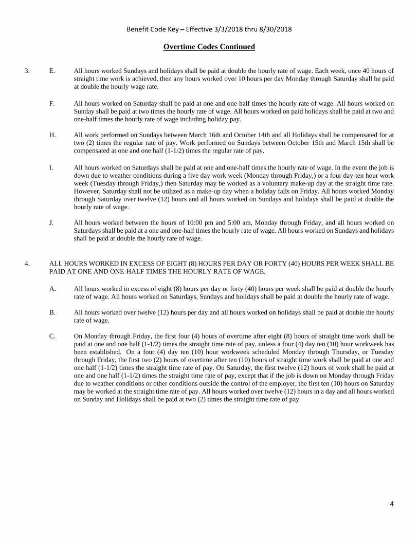
Benefit Code Key – Effective 3/3/2018 thru 8/30/2018
4
Overtime Codes Continued
3. E. All hours worked Sundays and holidays shall be paid at double the hourly rate of wage. Each week, once 40 hours of
straight time work is achieved, then any hours worked over 10 hours per day Monday through Saturday shall be paid at double the hourly wage rate.
F. All hours worked on Saturday shall be paid at one and one-half times the hourly rate of wage. All hours worked on
Sunday shall be paid at two times the hourly rate of wage. All hours worked on paid holidays shall be paid at two and one-half times the hourly rate of wage including holiday pay.
H. All work performed on Sundays between March 16th and October 14th and all Holidays shall be compensated for at
two (2) times the regular rate of pay. Work performed on Sundays between October 15th and March 15th shall be compensated at one and one half (1-1/2) times the regular rate of pay.
I. All hours worked on Saturdays shall be paid at one and one-half times the hourly rate of wage. In the event the job is down due to weather conditions during a five day work week (Monday through Friday,) or a four day-ten hour work week (Tuesday through Friday,) then Saturday may be worked as a voluntary make-up day at the straight time rate. However, Saturday shall not be utilized as a make-up day when a holiday falls on Friday. All hours worked Monday through Saturday over twelve (12) hours and all hours worked on Sundays and holidays shall be paid at double the hourly rate of wage.
J. All hours worked between the hours of 10:00 pm and 5:00 am, Monday through Friday, and all hours worked on
Saturdays shall be paid at a one and one-half times the hourly rate of wage. All hours worked on Sundays and holidays shall be paid at double the hourly rate of wage.
4. ALL HOURS WORKED IN EXCESS OF EIGHT (8) HOURS PER DAY OR FORTY (40) HOURS PER WEEK SHALL BE
PAID AT ONE AND ONE-HALF TIMES THE HOURLY RATE OF WAGE. A. All hours worked in excess of eight (8) hours per day or forty (40) hours per week shall be paid at double the hourly
rate of wage. All hours worked on Saturdays, Sundays and holidays shall be paid at double the hourly rate of wage. B. All hours worked over twelve (12) hours per day and all hours worked on holidays shall be paid at double the hourly
rate of wage. C. On Monday through Friday, the first four (4) hours of overtime after eight (8) hours of straight time work shall be
paid at one and one half (1-1/2) times the straight time rate of pay, unless a four (4) day ten (10) hour workweek has been established. On a four (4) day ten (10) hour workweek scheduled Monday through Thursday, or Tuesday through Friday, the first two (2) hours of overtime after ten (10) hours of straight time work shall be paid at one and one half (1-1/2) times the straight time rate of pay. On Saturday, the first twelve (12) hours of work shall be paid at one and one half (1-1/2) times the straight time rate of pay, except that if the job is down on Monday through Friday due to weather conditions or other conditions outside the control of the employer, the first ten (10) hours on Saturday may be worked at the straight time rate of pay. All hours worked over twelve (12) hours in a day and all hours worked on Sunday and Holidays shall be paid at two (2) times the straight time rate of pay.

Benefit Code Key – Effective 3/3/2018 thru 8/30/2018
5
Overtime Codes Continued 4. D. All hours worked in excess of eight (8) hours per day or forty (40) hours per week shall be paid at double the hourly
rate of wage. All hours worked on Saturday, Sundays and holidays shall be paid at double the hourly rate of pay. Rates include all members of the assigned crew.
EXCEPTION: On all multipole structures and steel transmission lines, switching stations, regulating, capacitor stations, generating plants, industrial plants, associated installations and substations, except those substations whose primary function is to feed a distribution system, will be paid overtime under the following rates: The first two (2) hours after eight (8) regular hours Monday through Friday of overtime on a regular workday, shall be paid at one and one-half times the hourly rate of wage. All hours in excess of ten (10) hours will be at two (2) times the hourly rate of wage. The first eight (8) hours worked on Saturday will be paid at one and one-half (1-1/2) times the hourly rate of wage. All hours worked in excess of eight (8) hours on Saturday, and all hours worked on Sundays and holidays will be at the double the hourly rate of wage. All overtime eligible hours performed on the above described work that is energized, shall be paid at the double the hourly rate of wage.
E. The first two (2) hours after eight (8) regular hours Monday through Friday and the first eight (8) hours on Saturday shall be paid at one and one-half times the hourly rate of wage. All other hours worked Monday through Saturday, and all hours worked on Sundays and holidays shall be paid at double the hourly rate of wage.
On a four-day, ten-hour weekly schedule, either Monday thru Thursday or Tuesday thru Friday schedule, all hours worked after ten shall be paid at double the hourly rate of wage. The Monday or Friday not utilized in the normal four-day, ten hour work week, and Saturday shall be paid at one and one half (1½) times the regular shift rate for the first eight (8) hours. All other hours worked Monday through Saturday, and all hours worked on Sundays and holidays shall be paid at double the hourly rate of wage.
F. All hours worked between the hours of 6:00 pm and 6:00 am, Monday through Saturday, shall be paid at a premium rate of 20% over the hourly rate of wage. All hours worked on Sundays shall be paid at one and one-half times the hourly rate of wage. All hours worked on holidays shall be paid at double the hourly rate of wage.
G. All hours worked on Saturdays shall be paid at one and one-half times the hourly rate of wage. All hours worked
Monday through Saturday over twelve (12) hours and all hours worked on Sundays and holidays shall be paid at double the hourly rate of wage.
H. The first two (2) hours after eight (8) regular hours Monday through Friday and the first eight (8) hours on Saturday
shall be paid at one and one-half times the hourly rate of wage. All other overtime hours worked, except Labor Day, and all hours on Sunday shall be paid at double the hourly rate of wage. All hours worked on Labor Day shall be paid at three times the hourly rate of wage.
Holiday Codes 5. A. Holidays: New Year's Day, Memorial Day, Independence Day, Labor Day, Thanksgiving Day, Friday after
Thanksgiving Day, and Christmas Day (7).
B. Holidays: New Year's Day, Memorial Day, Independence Day, Labor Day, Thanksgiving Day, Friday after Thanksgiving Day, the day before Christmas, and Christmas Day (8).
C. Holidays: New Year's Day, Presidents’ Day, Memorial Day, Independence Day, Labor Day, Thanksgiving Day, the
Friday after Thanksgiving Day, And Christmas Day (8).

Benefit Code Key – Effective 3/3/2018 thru 8/30/2018
6
Holiday Codes Continued 5. D. Holidays: New Year's Day, Memorial Day, Independence Day, Labor Day, Thanksgiving Day, the Friday and
Saturday after Thanksgiving Day, And Christmas Day (8).
H. Holidays: New Year's Day, Memorial Day, Independence Day, Thanksgiving Day, the Day after Thanksgiving Day, And Christmas (6).
I. Holidays: New Year's Day, Memorial Day, Independence Day, Labor Day, Thanksgiving Day, and Christmas Day
(6). J. Holidays: New Year's Day, Memorial Day, Independence Day, Thanksgiving Day, Friday after Thanksgiving Day,
Christmas Eve Day, And Christmas Day (7). K. Holidays: New Year’s Day, Presidents’ Day, Memorial Day, Independence Day, Labor Day, Thanksgiving Day,
Friday After Thanksgiving Day, The Day Before Christmas, And Christmas Day (9). L. Holidays: New Year’s Day, Martin Luther King Jr. Day, Memorial Day, Independence Day, Labor Day, Thanksgiving
Day, Friday after Thanksgiving Day, And Christmas Day (8).
N. Holidays: New Year's Day, Presidents’ Day, Memorial Day, Independence Day, Labor Day, Veterans' Day, Thanksgiving Day, The Friday After Thanksgiving Day, And Christmas Day (9).
P. Holidays: New Year's Day, Memorial Day, Independence Day, Labor Day, Thanksgiving Day, Friday And Saturday
After Thanksgiving Day, The Day Before Christmas, And Christmas Day (9). If A Holiday Falls On Sunday, The Following Monday Shall Be Considered As A Holiday.
Q. Paid Holidays: New Year's Day, Memorial Day, Independence Day, Labor Day, Thanksgiving Day, and Christmas
Day (6).
R. Paid Holidays: New Year's Day, Memorial Day, Independence Day, Labor Day, Thanksgiving Day, Day After Thanksgiving Day, One-Half Day Before Christmas Day, And Christmas Day. (7 1/2).
S. Paid Holidays: New Year's Day, Presidents’ Day, Memorial Day, Independence Day, Labor Day, Thanksgiving Day, And Christmas Day (7).
T. Paid Holidays: New Year's Day, Washington’s Birthday, Memorial Day, Independence Day, Labor Day,
Thanksgiving Day, The Friday After Thanksgiving Day, Christmas Day, And The Day Before Or After Christmas (9).
Z. Holidays: New Year's Day, Memorial Day, Independence Day, Labor Day, Veterans Day, Thanksgiving Day, the Friday after Thanksgiving Day, And Christmas Day (8).
6. A. Paid Holidays: New Year’s Day, Presidents’ Day, Memorial Day, Independence Day, Labor Day, Thanksgiving Day,
the Friday after Thanksgiving Day, And Christmas Day (8).
E. Paid Holidays: New Year's Day, Day Before Or After New Year's Day, Presidents Day, Memorial Day, Independence Day, Labor Day, Thanksgiving Day, the Friday after Thanksgiving Day, Christmas Day, and a Half-Day On Christmas Eve Day. (9 1/2).
G. Paid Holidays: New Year's Day, Martin Luther King Jr. Day, Presidents’ Day, Memorial Day, Independence Day,
Labor Day, Veterans' Day, Thanksgiving Day, the Friday after Thanksgiving Day, Christmas Day, and Christmas Eve Day (11).

Benefit Code Key – Effective 3/3/2018 thru 8/30/2018
7
Holiday Codes Continued
6. H. Paid Holidays: New Year's Day, New Year’s Eve Day, Memorial Day, Independence Day, Labor Day, Thanksgiving
Day, Friday After Thanksgiving Day, Christmas Day, The Day After Christmas, And A Floating Holiday (10). I. Paid Holidays: New Year's Day, Memorial Day, Independence Day, Labor Day, Thanksgiving Day, Friday
After Thanksgiving Day, And Christmas Day (7). T. Paid Holidays: New Year's Day, Presidents’ Day, Memorial Day, Independence Day, Labor Day,
Thanksgiving Day, The Friday After Thanksgiving Day, The Last Working Day Before Christmas Day, And Christmas Day (9).
Z. Holidays: New Year's Day, Memorial Day, Independence Day, Labor Day, Thanksgiving Day, Friday after
Thanksgiving Day, And Christmas Day (7). If a holiday falls on Saturday, the preceding Friday shall be considered as the holiday. If a holiday falls on Sunday, the following Monday shall be considered as the holiday.
7. A. Holidays: New Year's Day, Memorial Day, Independence Day, Labor Day, Thanksgiving Day, the Friday and
Saturday after Thanksgiving Day, And Christmas Day (8). Any Holiday Which Falls On A Sunday Shall Be Observed As A Holiday On The Following Monday. If any of the listed holidays falls on a Saturday, the preceding Friday shall be a regular work day.
B. Holidays: New Year's Day, Memorial Day, Independence Day, Labor Day, Thanksgiving Day, the Friday and
Saturday after Thanksgiving Day, And Christmas Day (8). Any holiday which falls on a Sunday shall be observed as a holiday on the following Monday. Any holiday which falls on a Saturday shall be observed as a holiday on the preceding Friday.
C. Holidays: New Year's Day, Martin Luther King Jr. Day, Memorial Day, Independence Day, Labor Day, Thanksgiving
Day, the Friday after Thanksgiving Day, And Christmas Day (8). Any holiday which falls on a Sunday shall be observed as a holiday on the following Monday. Any holiday which falls on a Saturday shall be observed as a holiday on the preceding Friday.
D. Paid Holidays: New Year's Day, Memorial Day, Independence Day, Labor Day, Veteran’s Day, Thanksgiving Day,
the Friday after Thanksgiving Day, And Christmas Day (8). Unpaid Holidays: President’s Day. Any paid holiday which falls on a Sunday shall be observed as a holiday on the following Monday. Any paid holiday which falls on a Saturday shall be observed as a holiday on the preceding Friday.
E. Holidays: New Year's Day, Memorial Day, Independence Day, Labor Day, Thanksgiving Day, the Friday after
Thanksgiving Day, And Christmas Day (7). Any holiday which falls on a Sunday shall be observed as a holiday on the following Monday. Any holiday which falls on a Saturday shall be observed as a holiday on the preceding Friday.
F. Holidays: New Year’s Day, Memorial Day, Independence Day, Labor Day, Thanksgiving Day, the Friday after
Thanksgiving Day, the last working day before Christmas day and Christmas day (8). Any holiday which falls on a Sunday shall be observed as a holiday on the following Monday. Any holiday which falls on a Saturday shall be observed as a holiday on the preceding Friday.
G. Holidays: New Year's Day, Memorial Day, Independence Day, Labor Day, Thanksgiving Day, and Christmas Day
(6). Any holiday which falls on a Sunday shall be observed as a holiday on the following Monday. H. Holidays: New Year's Day, Martin Luther King Jr. Day, Independence Day, Memorial Day, Labor Day, Thanksgiving
Day, the Friday after Thanksgiving Day, the Last Working Day before Christmas Day and Christmas Day (9). Any holiday which falls on a Sunday shall be observed as a holiday on the following Monday. Any holiday which falls on a Saturday shall be observed as a holiday on the preceding Friday.

Benefit Code Key – Effective 3/3/2018 thru 8/30/2018
8
Holiday Codes Continued 7. I. Holidays: New Year's Day, President’s Day, Independence Day, Memorial Day, Labor Day, Thanksgiving Day, The
Friday After Thanksgiving Day, The Day Before Christmas Day And Christmas Day (9). Any holiday which falls on a Sunday shall be observed as a holiday on the following Monday. Any holiday which falls on a Saturday shall be observed as a holiday on the preceding Friday.
J. Holidays: New Year's Day, Independence Day, Memorial Day, Labor Day, Thanksgiving Day and Christmas Day (6).
Any holiday which falls on a Sunday shall be observed as a holiday on the following Monday. Any holiday which falls on a Saturday shall be observed as a holiday on the preceding Friday.
K. Holidays: New Year's Day, Memorial Day, Independence Day, Thanksgiving Day, the Friday and Saturday after Thanksgiving Day, And Christmas Day (8). Any holiday which falls on a Sunday shall be observed as a holiday on the following Monday. Any holiday which falls on a Saturday shall be observed as a holiday on the preceding Friday.
L. Holidays: New Year's Day, Memorial Day, Labor Day, Independence Day, Thanksgiving Day, the Last Work Day
before Christmas Day, And Christmas Day (7). Any holiday which falls on a Sunday shall be observed as a holiday on the following Monday. Any holiday which falls on a Saturday shall be observed as a holiday on the preceding Friday.
M. Paid Holidays: New Year's Day, The Day after or before New Year’s Day, President’s Day, Memorial Day,
Independence Day, Labor Day, Thanksgiving Day, the Friday after Thanksgiving Day, Christmas Day, And the Day after or before Christmas Day (10). Any holiday which falls on a Sunday shall be observed as a holiday on the following Monday. Any holiday which falls on a Saturday shall be observed as a holiday on the preceding Friday.
N. Holidays: New Year's Day, Memorial Day, Independence Day, Labor Day, Thanksgiving Day, the Friday after
Thanksgiving Day, And Christmas Day (7). Any holiday which falls on a Sunday shall be observed as a holiday on the following Monday. When Christmas falls on a Saturday, the preceding Friday shall be observed as a holiday.
P. Holidays: New Year's Day, Memorial Day, Independence Day, Labor Day, Thanksgiving Day, Friday after Thanksgiving Day, And Christmas Day (7). Any holiday which falls on a Sunday shall be observed as a holiday on the following Monday.
Q. Holidays: New Year's Day, Memorial Day, Independence Day, Labor Day, Thanksgiving Day, the Friday after Thanksgiving Day, the Last Working Day before Christmas Day and Christmas Day (8). Any holiday which falls on a Sunday shall be observed as a holiday on the following Monday. If any of the listed holidays falls on a Saturday, the preceding Friday shall be a regular work day.
R. Paid Holidays: New Year's Day, the day after or before New Year’s Day, President’s Day, Memorial Day, Independence Day, Labor Day, Thanksgiving Day, the Friday after Thanksgiving Day, Christmas Day, and the day after or before Christmas Day (10). If any of the listed holidays fall on Saturday, the preceding Friday shall be observed as the holiday. If any of the listed holidays falls on a Sunday, the day observed by the Nation shall be considered a holiday and compensated accordingly.
S. Paid Holidays: New Year's Day, Memorial Day, Independence Day, Labor Day, Thanksgiving Day, Friday after
Thanksgiving Day, Christmas Day, the Day after Christmas, and A Floating Holiday (9). If any of the listed holidays falls on a Sunday, the day observed by the Nation shall be considered a holiday and compensated accordingly.
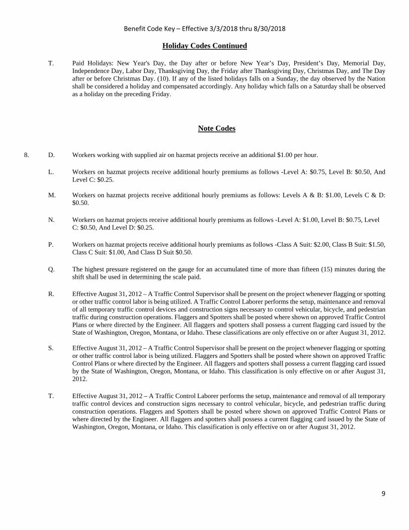
Benefit Code Key – Effective 3/3/2018 thru 8/30/2018
9
Holiday Codes Continued T. Paid Holidays: New Year's Day, the Day after or before New Year’s Day, President’s Day, Memorial Day,
Independence Day, Labor Day, Thanksgiving Day, the Friday after Thanksgiving Day, Christmas Day, and The Day after or before Christmas Day. (10). If any of the listed holidays falls on a Sunday, the day observed by the Nation shall be considered a holiday and compensated accordingly. Any holiday which falls on a Saturday shall be observed as a holiday on the preceding Friday.
Note Codes 8. D. Workers working with supplied air on hazmat projects receive an additional $1.00 per hour. L. Workers on hazmat projects receive additional hourly premiums as follows -Level A: $0.75, Level B: $0.50, And
Level C: $0.25. M. Workers on hazmat projects receive additional hourly premiums as follows: Levels A & B: $1.00, Levels C & D:
$0.50. N. Workers on hazmat projects receive additional hourly premiums as follows -Level A: $1.00, Level B: $0.75, Level
C: $0.50, And Level D: $0.25.
P. Workers on hazmat projects receive additional hourly premiums as follows -Class A Suit: $2.00, Class B Suit: $1.50, Class C Suit: $1.00, And Class D Suit $0.50.
Q. The highest pressure registered on the gauge for an accumulated time of more than fifteen (15) minutes during the
shift shall be used in determining the scale paid.
R. Effective August 31, 2012 – A Traffic Control Supervisor shall be present on the project whenever flagging or spotting or other traffic control labor is being utilized. A Traffic Control Laborer performs the setup, maintenance and removal of all temporary traffic control devices and construction signs necessary to control vehicular, bicycle, and pedestrian traffic during construction operations. Flaggers and Spotters shall be posted where shown on approved Traffic Control Plans or where directed by the Engineer. All flaggers and spotters shall possess a current flagging card issued by the State of Washington, Oregon, Montana, or Idaho. These classifications are only effective on or after August 31, 2012.
S. Effective August 31, 2012 – A Traffic Control Supervisor shall be present on the project whenever flagging or spotting or other traffic control labor is being utilized. Flaggers and Spotters shall be posted where shown on approved Traffic Control Plans or where directed by the Engineer. All flaggers and spotters shall possess a current flagging card issued by the State of Washington, Oregon, Montana, or Idaho. This classification is only effective on or after August 31, 2012.
T. Effective August 31, 2012 – A Traffic Control Laborer performs the setup, maintenance and removal of all temporary
traffic control devices and construction signs necessary to control vehicular, bicycle, and pedestrian traffic during construction operations. Flaggers and Spotters shall be posted where shown on approved Traffic Control Plans or where directed by the Engineer. All flaggers and spotters shall possess a current flagging card issued by the State of Washington, Oregon, Montana, or Idaho. This classification is only effective on or after August 31, 2012.

Benefit Code Key – Effective 3/3/2018 thru 8/30/2018
10
Note Codes Continued 8. U. Workers on hazmat projects receive additional hourly premiums as follows – Class A Suit: $2.00, Class B Suit: $1.50,
And Class C Suit: $1.00. Workers performing underground work receive an additional $0.40 per hour for any and all work performed underground, including operating, servicing and repairing of equipment. The premium for underground work shall be paid for the entire shift worked. Workers who work suspended by a rope or cable receive an additional $0.50 per hour. The premium for work suspended shall be paid for the entire shift worked. Workers who do “pioneer” work (break open a cut, build road, etc.) more than one hundred fifty (150) feet above grade elevation receive an additional $0.50 per hour.
V. In addition to the hourly wage and fringe benefits, the following depth and enclosure premiums shall be paid. The premiums are to be calculated for the maximum depth and distance into an enclosure that a diver reaches in a day. The premiums are to be paid one time for the day and are not used in calculating overtime pay. Depth premiums apply to depths of fifty feet or more. Over 50' to 100' - $2.00 per foot for each foot over 50 feet. Over 101' to 150' - $3.00 per foot for each foot over 101 feet. Over 151' to 220' - $4.00 per foot for each foot over 220 feet. Over 221' - $5.00 per foot for each foot over 221 feet. Enclosure premiums apply when divers enter enclosures (such as pipes or tunnels) where there is no vertical ascent and is measured by the distance travelled from the entrance. 25’ to 300’ - $1.00 per foot from entrance. 300’ to 600’ - $1.50 per foot beginning at 300’. Over 600’ - $2.00 per foot beginning at 600’.
W. Meter Installers work on single phase 120/240V self-contained residential meters. The Lineman/Groundmen rates would apply to meters not fitting this description.

PART 6
APPENDIX
APPENDIX A
GEOTECHNICAL REPORT(FOR INFORMATION ONLY)

________________________________________________
3213 Eastlake Avenue East, Suite B
Seattle, WA 98102
T. (206) 262-0370
F. (206)-262-0374
Geotechnical & Earthquake
Engineering Consultants
July 12, 2017
PanGEO Project No. 15-297
Mr. Steve Clarke, P.E.
Gray & Osborne, Inc.
701 Dexter Avenue North, Suite 200
Seattle, Washington 98109
Subject: Geotechnical Data Report
Well House #10
Milton, Washington
Dear Mr. Clarke,
PanGEO completed a geotechnical study for proposed well house #10 improvements for
the City of Milton, Washington. The well house is located in the City’s maintenance yard
located at 714 Kent Street in Milton, Washington, just west of the maintenance building.
The results of our study are presented in the attached report.
In summary, our borings encountered approximately 45 feet of poor soils, including
highly compressible peat. Field observations also indicate that, in addition to vertical
settlement, the ground surface in the vicinity of the proposed well house has experienced
significant lateral movements.
We appreciate the opportunity to be of service. Should you have any questions, please do
not hesitate to call.
Sincerely,
Siew L. Tan, P.E.
Principal Geotechnical Engineer

TABLE OF CONTENTS
Section Page
1.0 GENERAL .................................................................................................................1
2.0 SITE AND PROJECT DESCRIPTION......................................................................1
3.0 SUBSURFACE EXPLORATIONS ...........................................................................1
3.1 CURRENT TEST BORINGS ................................................................................1
3.2 PREVIOUS TEST BORINGS ................................................................................2
4.0 SUBSURFACE CONDITIONS .................................................................................2
4.1 SITE GEOLOGY ................................................................................................2
4.2 SOIL CONDITIONS ............................................................................................3
4.3 GROUNDWATER ..............................................................................................4
5.0 UNCERTAINTY AND LIMITATIONS ....................................................................4
6.0 REFERENCE .............................................................................................................6
ATTACHMENTS:
Figure 1. Vicinity Map
Figure 2. Site and Exploration Plan
Figure 3. Generalized Subsurface Profile, Section A
Appendix A Current Summary Boring Logs
Figure A-1 Terms and Symbols for Boring and Test Pit Logs
Figures A-2 to A-5 Boring Logs PG-1, PG-2, PG-2A, PG-3
Appendix B Previous Boring Logs
Boring Logs BH-1 through BH-5

GEOTECHNICAL DATA REPORT
WELL HOUSE #10
MILTON, WASHINGTON
1.0 GENERAL
PanGEO completed a geotechnical engineering study for the proposed well house #10
project at the City of Milton Public Works yard. The purpose of our geotechnical study
was to evaluate subsurface conditions at the site. Our services included a site
reconnaissance, drilling three test borings, and preparing this report.
2.0 SITE AND PROJECT DESCRIPTION
The project site is located at the City of Milton Public Works yard located at 714 Kent
Street in Milton, Washington (see Figure 1, Vicinity Map). The site is bound to the north
by an undeveloped wooded parcel, to the south by Kent Street, to the east by the
Interurban Trail, and to the west by two baseball playfields. The proposed well house #10
will be located near the existing well house #10. The existing and proposed site layout
are shown on the attached Figure 2.
The existing well house is an at-grade wood-frame structure. Based on our visual
observation, it appears that the building has experienced significant differential
settlement, as the west end of the building appears at least a foot lower than the east end.
We also observed a gap several inches wide between the entrance to the building and an
existing concrete ramp, suggesting the building has also moved laterally, in addition to
vertical settlement.
3.0 SUBSURFACE EXPLORATIONS
3.1 CURRENT TEST BORINGS
Three borings (PG-1, PG-2/PG-2A, and PG-3) were drilled at the site on December 14,
2015. The borings were located in the field by taping from existing site features and are
indicated on Figure 2. The borings were advanced to depths between 46 and 50 feet
below the existing grade.
The borings were drilled using an EC-95 trailer mounted drill rig owned and operated by
Boretec1, Inc. of Bellevue, Washington. The borings were drilled using a 6-inch outside
diameter hollow stem auger. Soil samples were obtained from the borings at 2½- and 5-

Geotechnical Data Report
Well House #10, City of Milton, WA
July 12, 2017
15-297 Milton Well House #10 Data Report Page 2 PanGEO, Inc.
foot depth intervals by means of Standard Penetration Test (SPT) sampling methods in
general accordance with ASTM test method D1586, in which the samples are obtained
using a 2-inch outside diameter split-spoon sampler. The sampler was driven into the soil
a distance of 18 inches using a 140-pound weight falling a distance of 30 inches. The
number of blows required for each 6-inch increment of sampler penetration was recorded.
The number of blows required to achieve the last 12 inches of sample penetration is
defined as the SPT N-value. The N-value provides an empirical measure of the relative
density of cohesionless soil, or the relative consistency of fine-grained soils.
During drilling for boring PG-2, drilling refusal was encountered at about 28 feet deep
due to an obstruction, likely a buried log. As a result, PG-2 was terminated at about 28
feet, and re-drilled at a location approximately 5 feet to the north. The replacement
boring is designated as PG-2A.
An engineer from PanGEO was present during the field explorations to observe the
drilling, to assist in sampling, and to describe and document the soil samples obtained
from the borings. The soil samples were described using the system outlined on Figure
A-1 in Appendix A. Logs of the individual borings drilled for this study are presented in
Figures A-2 through A-6 of Appendix A.
3.2 PREVIOUS TEST BORINGS
PanGEO previously completed several test borings for the proposed decant facility to be
constructed in the area north of the existing maintenance shop. These previous test
borings were designated as BH-1 through BH-5. The approximate locations of these
borings are indicated on the attached Figure 2. Summary logs are included in Appendix
B of this report for reference.
4.0 SUBSURFACE CONDITIONS
4.1 SITE GEOLOGY
Based on review of the Geologic Map of the Poverty Bay 7.5' quadrangle (Booth, 2004),
the surficial geologic unit in the vicinity of the subject site is recessional lacustrine
deposits (Map Unit Qvrl). Booth describes recessional lacustrine deposits as very fine
grained sand, silt, and clay deposited in small lakes during ice recession. In addition,
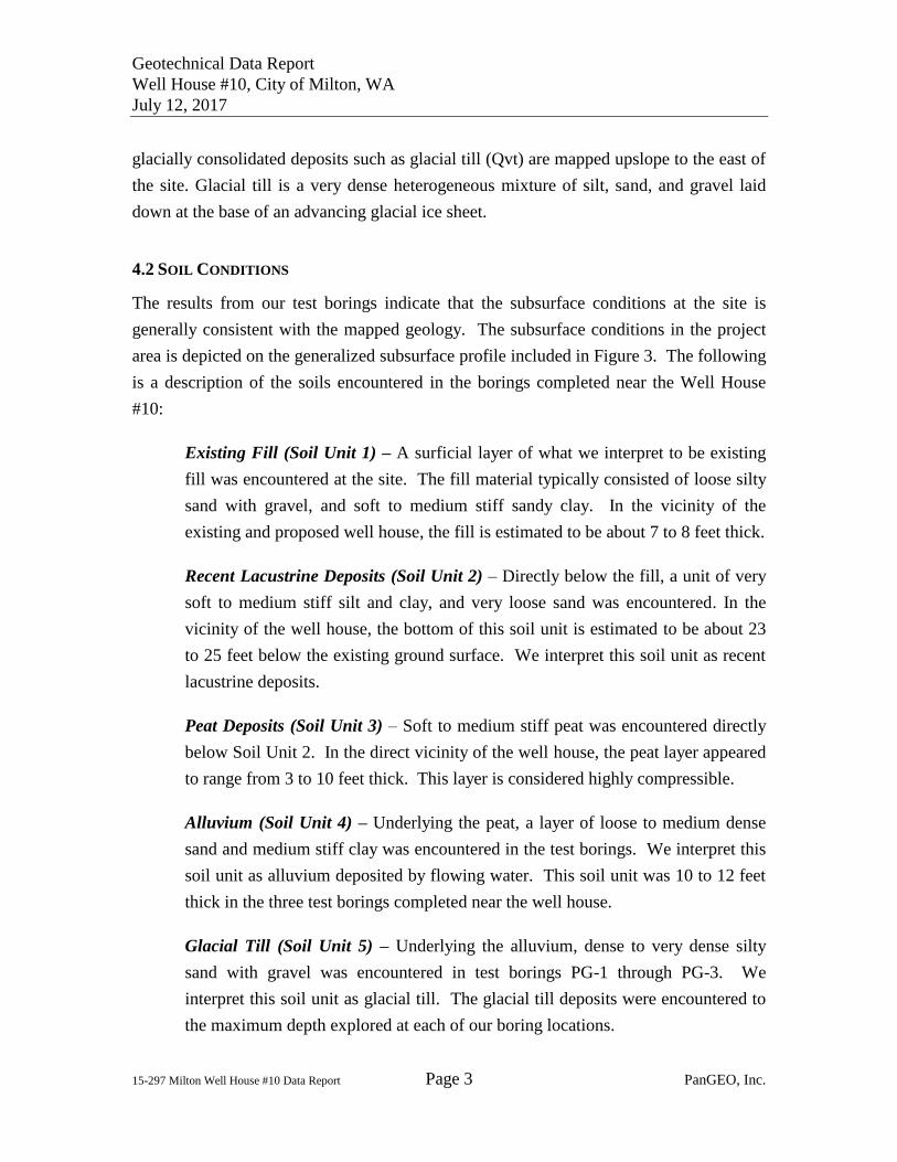
Geotechnical Data Report
Well House #10, City of Milton, WA
July 12, 2017
15-297 Milton Well House #10 Data Report Page 3 PanGEO, Inc.
glacially consolidated deposits such as glacial till (Qvt) are mapped upslope to the east of
the site. Glacial till is a very dense heterogeneous mixture of silt, sand, and gravel laid
down at the base of an advancing glacial ice sheet.
4.2 SOIL CONDITIONS
The results from our test borings indicate that the subsurface conditions at the site is
generally consistent with the mapped geology. The subsurface conditions in the project
area is depicted on the generalized subsurface profile included in Figure 3. The following
is a description of the soils encountered in the borings completed near the Well House
#10:
Existing Fill (Soil Unit 1) – A surficial layer of what we interpret to be existing
fill was encountered at the site. The fill material typically consisted of loose silty
sand with gravel, and soft to medium stiff sandy clay. In the vicinity of the
existing and proposed well house, the fill is estimated to be about 7 to 8 feet thick.
Recent Lacustrine Deposits (Soil Unit 2) – Directly below the fill, a unit of very
soft to medium stiff silt and clay, and very loose sand was encountered. In the
vicinity of the well house, the bottom of this soil unit is estimated to be about 23
to 25 feet below the existing ground surface. We interpret this soil unit as recent
lacustrine deposits.
Peat Deposits (Soil Unit 3) – Soft to medium stiff peat was encountered directly
below Soil Unit 2. In the direct vicinity of the well house, the peat layer appeared
to range from 3 to 10 feet thick. This layer is considered highly compressible.
Alluvium (Soil Unit 4) – Underlying the peat, a layer of loose to medium dense
sand and medium stiff clay was encountered in the test borings. We interpret this
soil unit as alluvium deposited by flowing water. This soil unit was 10 to 12 feet
thick in the three test borings completed near the well house.
Glacial Till (Soil Unit 5) – Underlying the alluvium, dense to very dense silty
sand with gravel was encountered in test borings PG-1 through PG-3. We
interpret this soil unit as glacial till. The glacial till deposits were encountered to
the maximum depth explored at each of our boring locations.

Geotechnical Data Report
Well House #10, City of Milton, WA
July 12, 2017
15-297 Milton Well House #10 Data Report Page 4 PanGEO, Inc.
4.3 GROUNDWATER
Groundwater seepage was encountered in our test borings at the time of drilling, between
6 and 7 feet deep. It should be noted that groundwater elevations and seepage rates are
likely to vary depending on the season, local subsurface conditions, and other factors.
Groundwater levels are normally highest during the winter and early spring. We
understand that the field located west of the site are occasionally flooded. As such, the
groundwater level may be quite close to the ground surface during such events.
5.0 UNCERTAINTY AND LIMITATIONS
We have prepared this report for use by Gray & Osborne and other project team
members. Recommendations contained in this report are based on a site reconnaissance,
a subsurface exploration program, review of pertinent geologic publications, and our
understanding of the project. The study was performed using a mutually agreed-upon
scope of work.
Variations in soil conditions may exist between the locations of the explorations and the
actual conditions underlying the site. The nature and extent of soil variations may not be
evident until construction occurs. If any soil conditions are encountered at the site that
are different from those described in this report, we should be notified immediately to
review the applicability of our recommendations. Additionally, we should also be
notified to review the applicability of our recommendations if there are any changes in the
project scope.
The scope of our work does not include services related to construction safety
precautions. Our recommendations are not intended to direct the contractors’ methods,
techniques, sequences or procedures, except as specifically described in our report for
consideration in design. Additionally, the scope of our work specifically excludes the
assessment of environmental characteristics, particularly those involving hazardous
substances. We are not mold consultants nor are our recommendations to be interpreted
as being preventative of mold development. A mold specialist should be consulted for all
mold-related issues.
This report may be used only by the client and for the purposes stated, within a reasonable
time from its issuance. Land use, site conditions (both off and on-site), or other factors
Geotechnical Data Report
Well House #10, City of Milton, WA
July 12, 2017
15-297 Milton Well House #10 Data Report Page 5 PanGEO, Inc.
including advances in our understanding of applied science, may change over time and
could materially affect our findings. Therefore, this report should not be relied upon after
24 months from its issuance. PanGEO should be notified if the project is delayed by
more than 24 months from the date of this report so that we may review the applicability
of our conclusions considering the time lapse.
It is the client’s responsibility to see that all parties to this project, including the designer,
contractor, subcontractors, etc., are made aware of this report in its entirety. The use of
information contained in this report for bidding purposes should be done at the
contractor’s option and risk. Any party other than the client who wishes to use this report
shall notify PanGEO of such intended use and for permission to copy this report. Based
on the intended use of the report, PanGEO may require that additional work be performed
and that an updated report be reissued. Noncompliance with any of these requirements
will release PanGEO from any liability resulting from the use this report.
Within the limitation of scope, schedule and budget, PanGEO engages in the practice of
geotechnical engineering and endeavors to perform its services in accordance with
generally accepted professional principles and practices at the time the Report or its
contents were prepared. No warranty, express or implied, is made.
We appreciate the opportunity to be of service to you on this project. Please feel free to
contact our office with any questions you have regarding our study, this report, or any
geotechnical engineering related project issues.
Sincerely,
Siew L. Tan, P.E.
Principal Geotechnical Engineer
Geotechnical Data Report
Well House #10, City of Milton, WA
July 12, 2017
15-297 Milton Well House #10 Data Report Page 6 PanGEO, Inc.
6.0 REFERENCE
Booth, D. B.; Waldron, H. H.; Troost, K. G., 2004, Geologic map of the Poverty Bay 7.5'
quadrangle, King and Pierce Counties, Washington: U.S. Geological Survey
Scientific Investigations Map 2854, 1 sheet, scale 1:24,000.

Figure No.Project No. 15-297
Milton Well House #10714 Kent Street
Milton, WA1
VICINITY MAP
15
-29
7F
ig1
Vic
inity.g
rf2
/4/1
6(1
4:0
7)
JM
Not to Scale
Subject Site
Note: Base map obtained and modified from Google Maps.

Project No. Figure No.
PG-1
PG-2
PG-3
BH-1
BH-2
BH-5
BH-4 BH-3
Milton Well House #10714 Kent Street
Milton, WA
SITE AND EXPLORATION PLAN
15-297 2
Legend:
Approx. Boring LocationsPanGEO Inc., Oct. 2014
Approx. Boring LocationsPanGEO Inc., Dec. 2015
Approx. Scale (feet)
Existing WellHouse
A'A
0 10 20 40
PG-2A

Project No. Figure No.
0 20 40 60Horizontal Scale (feet)
-20
-10
0
10
20
30
Ele
vatio
n (fe
et)
-20
-10
0
10
20
30
Ele
vatio
n (fe
et)
3
7
4
3
4
4
10
10
12
>50
441111168
>50>50
93410
>50>50
7
2
6
7
5
3
24
20
>50
>5048
123
1044
42
18219102620>50
41
Notes:1. Existing ground profile based on the topographic survey of 714 Kent Street
prepared by Gray & Osborne, Inc, 2015.2. See Figure 2 for location of Section A.3. See report text for a detailed explanation of the subsurface profile across the site.4. The generalized soil profile is based on widely-spaced borings. Soil conditions may vary over
a small distance, and the actual subsurface conditions may be different from the generalizedsoil profile depicted in this figure.
?
Soil description
Groundwater level
ApproximateGeologic Contact
SPT N-value(blows per foot)
BoringDesignation &Offset from Profile
?
LEGEND
Milton Well House #10714 Kent Street
Milton, WA
GENERALIZED SUBSURFACE PROFILESECTION A
15-297 3
PG-3(12' S)
PG-2(5' S)
PG-2A(11' S)
PG-1(3' N)
BH-1(16' N)
BH-2(21' S)
BH-5(16' N)
Existingground surfaceExisting
ground surface
Existing WellHouse #10
15-2
97 F
ig 3
Cro
ss S
ectio
n.gr
f 2/8
/16
(10:
46) J
M
Note: Vertical axis exaggerated by a factor of 2.
Fill
Recent Lacustrine
Peat
RecessionalOutwash
Glacial Till

APPENDIX A
CURRENT SUMMARY BORING LOGS

MOISTURE CONTENT
Layered:
Laminated:Lens:
Interlayered:Pocket:
Homogeneous:
Gravel
Approx. RelativeDensity (%)
Units of material distinguished by color and/orcomposition from material units above and belowLayers of soil typically 0.05 to 1mm thick, max. 1 cmLayer of soil that pinches out laterallyAlternating layers of differing soil materialErratic, discontinuous deposit of limited extentSoil with uniform color and composition throughout
GW
GP
GM
GC
SW
SP
SM
SC
ML
CL
OL
MH
CH
OH
PT
<1515 - 3535 - 6565 - 85
85 - 100
MONITORING WELL
Highly Organic Soils
Notes:
GROUP DESCRIPTIONSMAJOR DIVISIONSUNIFIED SOIL CLASSIFICATION SYSTEM
#4 to #10 sieve (4.5 to 2.0 mm)#10 to #40 sieve (2.0 to 0.42 mm)#40 to #200 sieve (0.42 to 0.074 mm)0.074 to 0.002 mm<0.002 mm
Liquid Limit < 50
Liquid Limit > 50
GRAVEL (<5% fines)
GRAVEL (>12% fines)
SAND (<5% fines)
SAND (>12% fines)
SILT / CLAY
Terms and Symbols forBoring and Test Pit Logs
Dusty, dry to the touch
Damp but no visible water
Visible free water
2-inch OD Split Spoon, SPT(140-lb. hammer, 30" drop)
3.25-inch OD Spilt Spoon(300-lb hammer, 30" drop)
Non-standard penetrationtest (see boring log for details)
Thin wall (Shelby) tube
Grab
Rock core
Vane Shear
Density Approx. Undrained ShearStrength (psf)
California Bearing RatioCompaction TestsConsolidationDry DensityDirect ShearFines ContentGrain SizePermeabilityPocket PenetrometerR-valueSpecific GravityTorvaneTriaxial CompressionUnconfined Compression
<44 to 1010 to 3030 to 50
>50
SPTN-values
Very LooseLooseMed. DenseDenseVery Dense
Breaks along defined planesFracture planes that are polished or glossyAngular soil lumps that resist breakdownSoil that is broken and mixedLess than one per footMore than one per footAngle between bedding plane and a planenormal to core axis
SPTN-values
<22 to 44 to 8
8 to 1515 to 30
>30
Sand Coarse Sand: Medium Sand: Fine Sand:SiltClay
Boulder:Cobbles:Gravel Coarse Gravel: Fine Gravel:
CBRComp
ConDDDS%FGS
PermPP
RSGTV
TXCUCC
Phone: 206.262.0370
Sand
Very SoftSoftMed. StiffStiffVery StiffHard
Bottom of Boring
Well-graded GRAVEL
Poorly-graded GRAVEL
Silty GRAVEL
Clayey GRAVEL
Well-graded SAND
Poorly-graded SAND
Silty SAND
Clayey SAND
SILT
Lean CLAY
Organic SILT or CLAY
Elastic SILT
Fat CLAY
Organic SILT or CLAY
PEAT
DESCRIPTIONS OF SOIL STRUCTURES
50% or more of the coarsefraction retained on the #4sieve. Use dual symbols (eg.GP-GM) for 5% to 12% fines.
> 12 inches3 to 12 inches
3 to 3/4 inches3/4 inches to #4 sieve
Figure A-1
50% or more of the coarsefraction passing the #4 sieve.Use dual symbols (eg. SP-SM)for 5% to 12% fines.
for In Situ and Laboratory Testslisted in "Other Tests" column.
<250250 - 500
500 - 10001000 - 20002000 - 4000
>4000
Dry
Moist
Wet
COMPONENT DEFINITIONS
Fissured:Slickensided:
Blocky:Disrupted:Scattered:
Numerous:BCN:
RELATIVE DENSITY / CONSISTENCY
COMPONENT SIZE / SIEVE RANGE
Groundwater Level at time of drilling (ATD)Static Groundwater Level
Cement / Concrete Seal
Bentonite grout / seal
Silica sand backfill
Slotted tip
Slough
50%or more passing #200 sieve
LOG
KEY
07-
041_
EVER
ETT_
AS.G
PJ P
ANG
EO.G
DT
5/1
/07
SYMBOLS
SAND / GRAVELConsistency
Silt and Clay
Sample/In Situ test types and intervals
1. Soil exploration logs contain material descriptions based on visual observation and field tests using a systemmodified from the Uniform Soil Classification System (USCS). Where necessary laboratory tests have beenconducted (as noted in the "Other Tests" column), unit descriptions may include a classification. Please refer to thediscussions in the report text for a more complete description of the subsurface conditions.
2. The graphic symbols given above are not inclusive of all symbols that may appear on the borehole logs.Other symbols may be used where field observations indicated mixed soil constituents or dual constituent materials.
COMPONENT SIZE / SIEVE RANGE
TEST SYMBOLS

UNIT 1: FillLoose, moist to wet, brown, silty gravelly SAND with trace roots (Fill).
- tarce brown iron oxide staining.
UNIT 2: Recent Lacustrine DepositsSoft to medium stiff, moist to wet, blue-gray to gray, sandy CLAY withtrace to some gravel (CL).
- trace organic wood pieces.
- trace organic peat.
UNIT 3: PeatSoft to medium stiff, moist, dark brown, woody PEAT (PT).
S-1
S-2
S-3
S-4
S-5
643
211
324
434
223
Remarks: Boring drilled with an EC-95 track-mounted drill rig equipped with safetyhammer (cathead mechanism) for SPT.
0
5
10
15
20
25
30
The stratification lines represent approximate boundaries. The transition may be gradual.
MATERIAL DESCRIPTION
Figure A-2
Oth
er T
ests
Sam
ple
No.
Completion Depth:Date Borehole Started:Date Borehole Completed:Logged By:Drilling Company:
Dep
th, (
ft)Well House #10 Reconstruction15-297714 Kent Street, Milton, WANorthing: , Easting:
45.9ft12/14/1512/14/15JCBoretec1, Inc.
Sheet 1 of 2
Project:Job Number:Location:Coordinates:
Sym
bol
Sam
ple
Type
Blo
ws
/ 6 in
.
Not AvailableN/AHollow Stem AugerSPT
Surface Elevation:Top of Casing Elev.:Drilling Method:Sampling Method:
LOG OF TEST BORING PG-1
N-Value
0
Moisture LL
50
PL
RQD Recovery100

UNIT 3: PeatSoft to medium stiff, moist, dark brown, woody PEAT (PT).(Continued)
UNIT 4: AlluviumMedium dense, wet, gray, silty SAND with some gravel (SM).
UNIT 5: Glacial Till Very dense, wet, sandy SILT with gravel (ML).
Boring terminated at approximately 49.5 feet below grade.Groundwater encountered at 8 feet below grade during the time ofdrilling.
S-6
S-7
S-8
S-9
212
41014
6812
2250/5
Remarks: Boring drilled with an EC-95 track-mounted drill rig equipped with safetyhammer (cathead mechanism) for SPT.
30
35
40
45
50
55
60
The stratification lines represent approximate boundaries. The transition may be gradual.
MATERIAL DESCRIPTION
Figure A-2
Oth
er T
ests
Sam
ple
No.
Completion Depth:Date Borehole Started:Date Borehole Completed:Logged By:Drilling Company:
Dep
th, (
ft)Well House #10 Reconstruction15-297714 Kent Street, Milton, WANorthing: , Easting:
45.9ft12/14/1512/14/15JCBoretec1, Inc.
Sheet 2 of 2
Project:Job Number:Location:Coordinates:
Sym
bol
Sam
ple
Type
Blo
ws
/ 6 in
.
Not AvailableN/AHollow Stem AugerSPT
Surface Elevation:Top of Casing Elev.:Drilling Method:Sampling Method:
LOG OF TEST BORING PG-1
N-Value
0
Moisture LL
50
PL
RQD Recovery100
330.4
>>

UNIT 1: FillSoft, moist to wet, gray-brown, sandy CLAY with trace gravel to CLAYwith some sand (Fill).
- trace brown organic wood debris.
UNIT 2: Recent Lacustrine DepositsVery soft, moist to wet, blue-gray to gray, sandy CLAY with somegravel to silty CLAY with some sand and trace gravel (CL).
Very loose, wet, gray, clayey SAND with some gravel (SC).
Soft to medium stiff, wet, gray, sandy CLAY with trace gravel to siltyCLAY with some sand (CL).
- trace wood pieces.
Medium stiff, moist, sandy SILT with trace gravel, some wood debris(ML).
UNIT 3: PeatBrown wood log.
Boring terminated at approximately 28.3 feet below grade due torefusal. Groundwater measured at 5 feet below grade one hour afterdrilling.
S-1
S-2
S-3
S-4
S-5
S-6
S-7
S-8
S-9
S-10
S-11
322
222
111
111
111
211
211
224
444
1430
50/5
3050/4
Remarks: Boring drilled with an EC-95 track-mounted drill rig equipped with safetyhammer (cathead mechanism) for SPT.
0
5
10
15
20
25
30
The stratification lines represent approximate boundaries. The transition may be gradual.
MATERIAL DESCRIPTION
Figure A-3
Oth
er T
ests
Sam
ple
No.
Completion Depth:Date Borehole Started:Date Borehole Completed:Logged By:Drilling Company:
Dep
th, (
ft)Well House #10 Reconstruction15-297714 Kent Street, Milton, WANorthing: , Easting:
28.3ft12/14/1512/14/15JCBoretec1, Inc.
Sheet 1 of 1
Project:Job Number:Location:Coordinates:
Sym
bol
Sam
ple
Type
Blo
ws
/ 6 in
.
Not AvailableN/AHollow Stem AugerSPT
Surface Elevation:Top of Casing Elev.:Drilling Method:Sampling Method:
LOG OF TEST BORING PG-2
N-Value
0
Moisture LL
50
PL
RQD Recovery100
>>
>>

UNIT 3: PeatBrown wood log.S-1
S-2
4108
5129
Remarks: Boring drilled with an EC-95 track-mounted drill rig equipped with safetyhammer (cathead mechanism) for SPT.
0
5
10
15
20
25
30
The stratification lines represent approximate boundaries. The transition may be gradual.
MATERIAL DESCRIPTION
Figure A-4
Oth
er T
ests
Sam
ple
No.
Completion Depth:Date Borehole Started:Date Borehole Completed:Logged By:Drilling Company:
Dep
th, (
ft)Well House #10 Reconstruction15-297714 Kent Street, Milton, WANorthing: , Easting:
46.5ft12/14/1512/14/15JCBoretec1, Inc.
Sheet 1 of 2
Project:Job Number:Location:Coordinates:
Sym
bol
Sam
ple
Type
Blo
ws
/ 6 in
.
Not AvailableN/AHollow Stem AugerSPT
Surface Elevation:Top of Casing Elev.:Drilling Method:Sampling Method:
LOG OF TEST BORING PG-2A
N-Value
0
Moisture LL
50
PL
RQD Recovery100

UNIT 4: AlluviumLoose to medium dense, wet, dark gray, silty sand with trace gravel,some organic wood debris (SM). (Continued)
Medium dense, wet, gray, clayey SAND with some gravel (SC).
- becomes clay with some sand.
UNIT 5: Glacial TillDense to very dense, wet, gray, silty SAND with some gravel to clayeygravelly SAND (SM).
Boring terminated at approximately 46.5 feet below grade due torefusal. Groundwater measured at 5 feet below grade one hour afterdrilling.
S-3
S-4
S-5
S-6
S-7
S-8
454
555
51016
5416
62730
111922
Remarks: Boring drilled with an EC-95 track-mounted drill rig equipped with safetyhammer (cathead mechanism) for SPT.
30
35
40
45
50
55
60
The stratification lines represent approximate boundaries. The transition may be gradual.
MATERIAL DESCRIPTION
Figure A-4
Oth
er T
ests
Sam
ple
No.
Completion Depth:Date Borehole Started:Date Borehole Completed:Logged By:Drilling Company:
Dep
th, (
ft)Well House #10 Reconstruction15-297714 Kent Street, Milton, WANorthing: , Easting:
46.5ft12/14/1512/14/15JCBoretec1, Inc.
Sheet 2 of 2
Project:Job Number:Location:Coordinates:
Sym
bol
Sam
ple
Type
Blo
ws
/ 6 in
.
Not AvailableN/AHollow Stem AugerSPT
Surface Elevation:Top of Casing Elev.:Drilling Method:Sampling Method:
LOG OF TEST BORING PG-2A
N-Value
0
Moisture LL
50
PL
RQD Recovery100

UNIT 1: FillVery loose, moist to wet, dark brown, silty SAND with trace roots (Fill).
UNIT 2: Reccent Lacustrine DepositsMedium Stiff, wet, dark brown to blue gray, sandy CLAY with tracegravel (Fill).
UNIT 3: PeatVery soft to soft, moist, dark brown, woody PEAT (PT).
S-1
S-2
S-3
S-4
S-5
221
434
222
221
222
Remarks: Boring drilled with an EC-95 track-mounted drill rig equipped with safetyhammer (cathead mechanism) for SPT.
0
5
10
15
20
25
30
The stratification lines represent approximate boundaries. The transition may be gradual.
MATERIAL DESCRIPTION
Figure A-5
Oth
er T
ests
Sam
ple
No.
Completion Depth:Date Borehole Started:Date Borehole Completed:Logged By:Drilling Company:
Dep
th, (
ft)Well House #10 Reconstruction15-297714 Kent Street, Milton, WANorthing: , Easting:
50.3ft12/14/1512/14/15JCBoretec1, Inc.
Sheet 1 of 2
Project:Job Number:Location:Coordinates:
Sym
bol
Sam
ple
Type
Blo
ws
/ 6 in
.
Not AvailableN/AHollow Stem AugerSPT
Surface Elevation:Top of Casing Elev.:Drilling Method:Sampling Method:
LOG OF TEST BORING PG-3
N-Value
0
Moisture LL
50
PL
RQD Recovery100
288.8
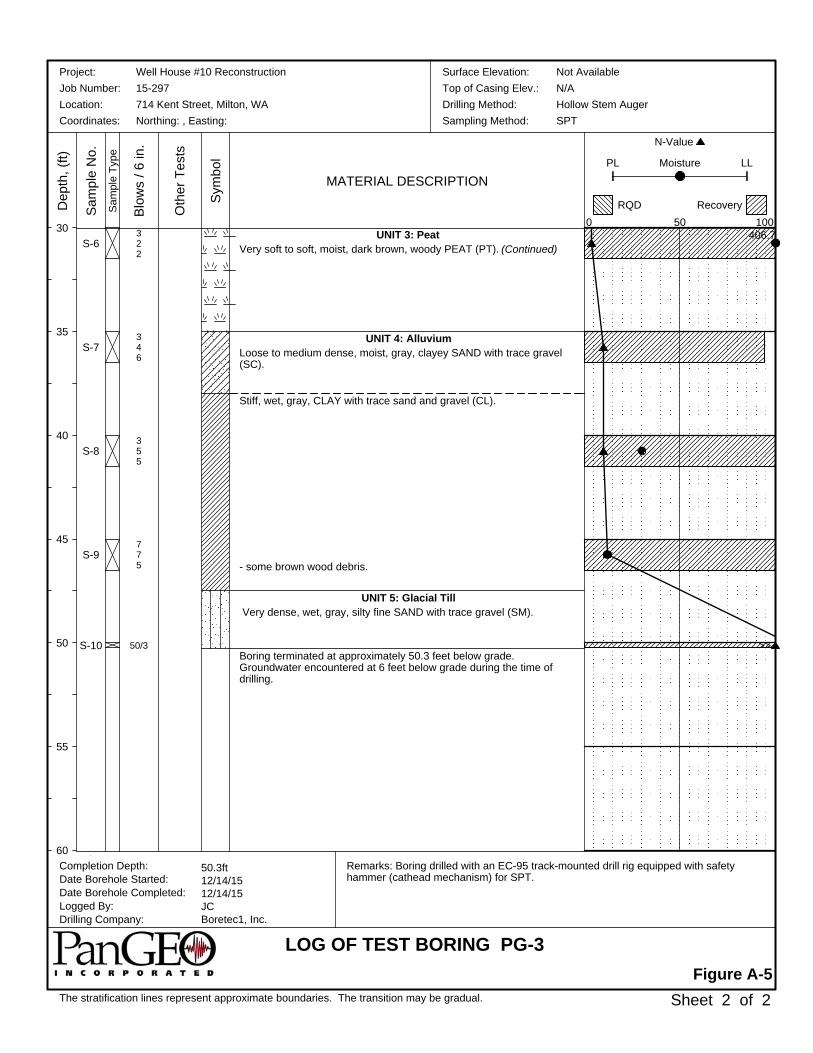
UNIT 3: PeatVery soft to soft, moist, dark brown, woody PEAT (PT). (Continued)
UNIT 4: AlluviumLoose to medium dense, moist, gray, clayey SAND with trace gravel(SC).
Stiff, wet, gray, CLAY with trace sand and gravel (CL).
- some brown wood debris.
UNIT 5: Glacial Till Very dense, wet, gray, silty fine SAND with trace gravel (SM).
Boring terminated at approximately 50.3 feet below grade.Groundwater encountered at 6 feet below grade during the time ofdrilling.
S-6
S-7
S-8
S-9
S-10
322
346
355
775
50/3
Remarks: Boring drilled with an EC-95 track-mounted drill rig equipped with safetyhammer (cathead mechanism) for SPT.
30
35
40
45
50
55
60
The stratification lines represent approximate boundaries. The transition may be gradual.
MATERIAL DESCRIPTION
Figure A-5
Oth
er T
ests
Sam
ple
No.
Completion Depth:Date Borehole Started:Date Borehole Completed:Logged By:Drilling Company:
Dep
th, (
ft)Well House #10 Reconstruction15-297714 Kent Street, Milton, WANorthing: , Easting:
50.3ft12/14/1512/14/15JCBoretec1, Inc.
Sheet 2 of 2
Project:Job Number:Location:Coordinates:
Sym
bol
Sam
ple
Type
Blo
ws
/ 6 in
.
Not AvailableN/AHollow Stem AugerSPT
Surface Elevation:Top of Casing Elev.:Drilling Method:Sampling Method:
LOG OF TEST BORING PG-3
N-Value
0
Moisture LL
50
PL
RQD Recovery100
406.7
>>

APPENDIX B
PREVIOUS BORING LOGS
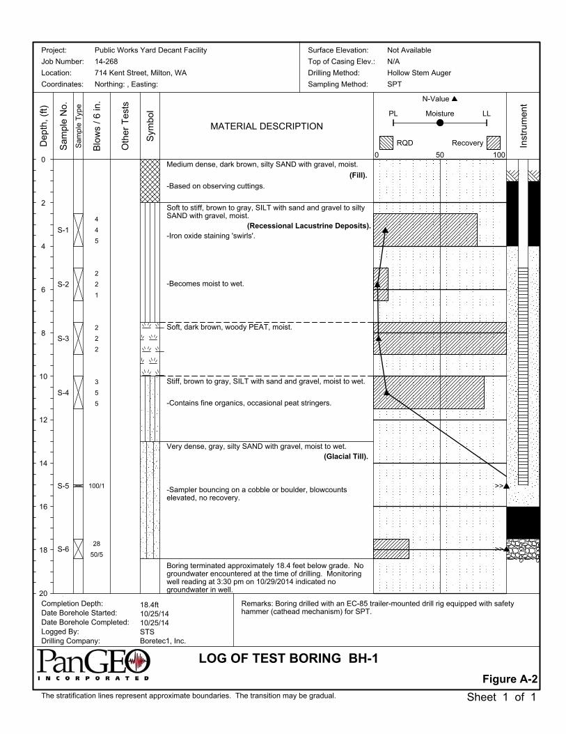
Medium dense, dark brown, silty SAND with gravel, moist.
(Fill).
-Based on observing cuttings.
Soft to stiff, brown to gray, SILT with sand and gravel to siltySAND with gravel, moist.
(Recessional Lacustrine Deposits).-Iron oxide staining 'swirls'.
-Becomes moist to wet.
Soft, dark brown, woody PEAT, moist.
Stiff, brown to gray, SILT with sand and gravel, moist to wet.
-Contains fine organics, occasional peat stringers.
Very dense, gray, silty SAND with gravel, moist to wet.(Glacial Till).
-Sampler bouncing on a cobble or boulder, blowcountselevated, no recovery.
Boring terminated approximately 18.4 feet below grade. Nogroundwater encountered at the time of drilling. Monitoringwell reading at 3:30 pm on 10/29/2014 indicated nogroundwater in well.
S-1
S-2
S-3
S-4
S-5
S-6
4
4
5
2
2
1
2
2
2
3
5
5
100/1
28
50/5
Remarks: Boring drilled with an EC-85 trailer-mounted drill rig equipped with safetyhammer (cathead mechanism) for SPT.
0
2
4
6
8
10
12
14
16
18
20
The stratification lines represent approximate boundaries. The transition may be gradual.
MATERIAL DESCRIPTION
Figure A-2
Oth
er T
ests
Sam
ple
No.
Completion Depth:Date Borehole Started:Date Borehole Completed:Logged By:Drilling Company:
Dep
th,
(ft)
Public Works Yard Decant Facility
14-268
714 Kent Street, Milton, WA
Northing: , Easting:
18.4ft10/25/1410/25/14STSBoretec1, Inc.
Sheet 1 of 1
Project:
Job Number:
Location:
Coordinates:
Sym
bol
Sam
ple
Typ
e
Blo
ws
/ 6
in.
Not Available
N/A
Hollow Stem Auger
SPT
Surface Elevation:
Top of Casing Elev.:
Drilling Method:
Sampling Method:
LOG OF TEST BORING BH-1
N-Value
0
Moisture LL
50
PL
RQD Recovery
100
Inst
rum
ent
>>
>>

Medium dense, dark brown to gray, silty SAND with gravel, moist.
(Fill).
-Occasional organics and concrete debris in cuttings.
Soft, gray, sandy SILT with gravel, moist.(Recessional Lacustrine Deposits).
Soft, dark brown, woody PEAT, moist.
Soft to stiff, greenish-gray, SILT with sand and gravel, moist to wet.
-Contains fine organics, occasional peat stringers, iron oxide staining.
Dense, gray, silty SAND with gravel, moist. Weathered.(Glacial Till).
-Becomes brown to gray, iron oxide staining.
Boring terminated approximately 16.5 feet below grade. Perchedgroundwater encountered approximately 9 feet below grade at thetime of drilling.
S-1
S-2
S-3
S-4
S-5
5
8
4
1
1
2
2
1
9
18
20
24
18
17
27
Remarks: Boring drilled with an EC-85 trailer-mounted drill rig equipped with safetyhammer (cathead mechanism) for SPT.
0
2
4
6
8
10
12
14
16
18
20
The stratification lines represent approximate boundaries. The transition may be gradual.
MATERIAL DESCRIPTION
Figure A-3
Oth
er T
ests
Sam
ple
No.
Completion Depth:Date Borehole Started:Date Borehole Completed:Logged By:Drilling Company:
Dep
th,
(ft)
Public Works Yard Decant Facility
14-268
714 Kent Street, Milton, WA
Northing: , Easting:
16.5ft10/25/1410/25/14STSBoretec1, Inc.
Sheet 1 of 1
Project:
Job Number:
Location:
Coordinates:
Sym
bol
Sam
ple
Typ
e
Blo
ws
/ 6
in.
Not Available
N/A
Hollow Stem Auger
SPT
Surface Elevation:
Top of Casing Elev.:
Drilling Method:
Sampling Method:
LOG OF TEST BORING BH-2
N-Value
0
Moisture LL
50
PL
RQD Recovery
100

Medium dense, dark brown, silty SAND with gravel, moist.
(Fill).
-Based on observing cuttings.
Very dense, brownish-gray, silty SAND with gravel, moist.(Glacial Till).
-Low recovery, large gravel in tip of sampler, blowcounts elevated.
Boring terminated approximately 11 feet below grade. Groundwaterwas not encountered at the time of drilling.
S-1
S-2
S-3
S-4
20
40
50/5
29
40
50
19
36
46
33
50/6
Remarks: Boring drilled with an EC-85 trailer-mounted drill rig equipped with safetyhammer (cathead mechanism) for SPT.
0
2
4
6
8
10
12
14
16
18
20
The stratification lines represent approximate boundaries. The transition may be gradual.
MATERIAL DESCRIPTION
Figure A-4
Oth
er T
ests
Sam
ple
No.
Completion Depth:Date Borehole Started:Date Borehole Completed:Logged By:Drilling Company:
Dep
th,
(ft)
Public Works Yard Decant Facility
14-268
714 Kent Street, Milton, WA
Northing: , Easting:
11.0ft10/25/1410/25/14STSBoretec1, Inc.
Sheet 1 of 1
Project:
Job Number:
Location:
Coordinates:
Sym
bol
Sam
ple
Typ
e
Blo
ws
/ 6
in.
Not Available
N/A
Hollow Stem Auger
SPT
Surface Elevation:
Top of Casing Elev.:
Drilling Method:
Sampling Method:
LOG OF TEST BORING BH-3
N-Value
0
Moisture LL
50
PL
RQD Recovery
100
>>
>>

Medium dense, dark brown, silty SAND with gravel, moist.
(Fill).
Medium stiff, bluish-green, sandy SILT with gravel, moist.(Recessional Lacustrine Deposits).
-Laminated, mottles, contains fine organics and occasional peatstringers. Organic content decreases with depth in sample S-2.
Dense, gray, silty SAND with gravel, moist. Weathered.(Glacial Till).
Boring terminated approximately 11.5 feet below grade. Groundwaterwas not encountered at the time of drilling.
S-1
S-2
S-3
S-4
11
13
9
2
4
3
15
15
17
15
26
24
Remarks: Boring drilled with an EC-85 trailer-mounted drill rig equipped with safetyhammer (cathead mechanism) for SPT.
0
2
4
6
8
10
12
14
16
18
20
The stratification lines represent approximate boundaries. The transition may be gradual.
MATERIAL DESCRIPTION
Figure A-5
Oth
er T
ests
Sam
ple
No.
Completion Depth:Date Borehole Started:Date Borehole Completed:Logged By:Drilling Company:
Dep
th,
(ft)
Public Works Yard Decant Facility
14-268
714 Kent Street, Milton, WA
Northing: , Easting:
11.5ft10/25/1410/25/14STSBoretec1, Inc.
Sheet 1 of 1
Project:
Job Number:
Location:
Coordinates:
Sym
bol
Sam
ple
Typ
e
Blo
ws
/ 6
in.
Not Available
N/A
Hollow Stem Auger
SPT
Surface Elevation:
Top of Casing Elev.:
Drilling Method:
Sampling Method:
LOG OF TEST BORING BH-4
N-Value
0
Moisture LL
50
PL
RQD Recovery
100

Medium dense, dark brown, silty SAND with gravel, moist.
(Fill).
-Based on observing cuttings.
Very dense, brownish-gray to gray, silty SAND with gravel, moist.(Glacial Till).
-Iron oxide staining.
Boring terminated approximately 9 feet below grade. Groundwaterwas not encountered at the time of drilling.
S-1
S-2
13
50/6
27
24
24
Remarks: Boring drilled with an EC-85 trailer-mounted drill rig equipped with safetyhammer (cathead mechanism) for SPT.
0
2
4
6
8
10
12
14
16
18
20
The stratification lines represent approximate boundaries. The transition may be gradual.
MATERIAL DESCRIPTION
Figure A-6
Oth
er T
ests
Sam
ple
No.
Completion Depth:Date Borehole Started:Date Borehole Completed:Logged By:Drilling Company:
Dep
th,
(ft)
Public Works Yard Decant Facility
14-268
714 Kent Street, Milton, WA
Northing: , Easting:
9.0ft10/25/1410/25/14STSBoretec1, Inc.
Sheet 1 of 1
Project:
Job Number:
Location:
Coordinates:
Sym
bol
Sam
ple
Typ
e
Blo
ws
/ 6
in.
Not Available
N/A
Hollow Stem Auger
SPT
Surface Elevation:
Top of Casing Elev.:
Drilling Method:
Sampling Method:
LOG OF TEST BORING BH-5
N-Value
0
Moisture LL
50
PL
RQD Recovery
100
>>
APPENDIX B
EXISTING WELL LOGS

Medium dense, dark brown, silty SAND with gravel, moist.
(Fill).
-Based on observing cuttings.
Soft to stiff, brown to gray, SILT with sand and gravel to siltySAND with gravel, moist.
(Recessional Lacustrine Deposits).-Iron oxide staining 'swirls'.
-Becomes moist to wet.
Soft, dark brown, woody PEAT, moist.
Stiff, brown to gray, SILT with sand and gravel, moist to wet.
-Contains fine organics, occasional peat stringers.
Very dense, gray, silty SAND with gravel, moist to wet.(Glacial Till).
-Sampler bouncing on a cobble or boulder, blowcountselevated, no recovery.
Boring terminated approximately 18.4 feet below grade. Nogroundwater encountered at the time of drilling. Monitoringwell reading at 3:30 pm on 10/29/2014 indicated nogroundwater in well.
S-1
S-2
S-3
S-4
S-5
S-6
4
4
5
2
2
1
2
2
2
3
5
5
100/1
28
50/5
Remarks: Boring drilled with an EC-85 trailer-mounted drill rig equipped with safetyhammer (cathead mechanism) for SPT.
0
2
4
6
8
10
12
14
16
18
20
The stratification lines represent approximate boundaries. The transition may be gradual.
MATERIAL DESCRIPTION
Figure A-2
Oth
er T
ests
Sam
ple
No.
Completion Depth:Date Borehole Started:Date Borehole Completed:Logged By:Drilling Company:
Dep
th,
(ft)
Public Works Yard Decant Facility
14-268
714 Kent Street, Milton, WA
Northing: , Easting:
18.4ft10/25/1410/25/14STSBoretec1, Inc.
Sheet 1 of 1
Project:
Job Number:
Location:
Coordinates:
Sym
bol
Sam
ple
Typ
e
Blo
ws
/ 6
in.
Not Available
N/A
Hollow Stem Auger
SPT
Surface Elevation:
Top of Casing Elev.:
Drilling Method:
Sampling Method:
LOG OF TEST BORING BH-1
N-Value
0
Moisture LL
50
PL
RQD Recovery
100
Inst
rum
ent
>>
>>

