california high-speed train project€¦ · prepared by for the california high-speed rail...
TRANSCRIPT
Prepared by
for the California High-Speed Rail Authority
California High-Speed Train Project
TECHNICAL MEMORANDUM
Structure Design Loads TM 2.3.2
Prepared by:
Signed document on file
20 Apr 11 Tom Jackson, PE Date
Checked by:
Signed document on file
24 June 11 P.Y. Lin, PE Date
Approved by:
Signed document on file
30 June 11
Ken Jong, PE Engineering Manager
Date
Released by:
Signed document on file
08 July 11
Hans Van Winkle, Program Director
Date
Revision Date Description 0 02 Jun 09 Issued for 15% Design; Initial Release, R0
1 17 Jun 10 Issued for 30% Design; includes additional HST structural impact factors and addresses Caltrans comments
2 20 Apr 11 Issued for 30% Design; Includes conventional rail loading
Note: Signatures apply for the latest technical memorandum revision as noted above.
California High-Speed Train Project Structure Design Loads, R2
This document has been prepared by Parsons Brinckerhoff for the California High-Speed Rail Authority and for application to the California High-Speed Train Project. Any use of this document for purposes other than this Project, or the specific portion of the Project stated in the document, shall be at the sole risk of the user, and without liability to PB for any losses or injuries arising for such use.
California High-Speed Train Project Structure Design Loads, R2
Page i
System Level Technical and Integration Reviews The purpose of the review is to ensure:
- Technical consistency and appropriateness - Check for integration issues and conflicts
System level reviews are required for all technical memoranda. Technical Leads for each subsystem are responsible for completing the reviews in a timely manner and identifying appropriate senior staff to perform the review. Exemption to the system level technical and integration review by any subsystem must be approved by the Engineering Manager.
System Level Technical Reviews by Subsystem:
Systems:
NOT REQUIRED
DD Month YY Print Name: Date
Infrastructure:
Signed document on file
22 May 11 P.Y. Lin, PE Date
Operations:
NOT REQUIRED
DD Month YY Print Name: Date
Maintenance:
NOT REQUIRED
DD Month YY Print Name: Date
Rolling Stock:
NOT REQUIRED
DD Month YY Print Name: Date
Note: Signatures apply for the technical memorandum revision corresponding to revision number in header and as noted on cover.
California High-Speed Train Project Structure Design Loads, R2
Page ii
TABLE OF CONTENTS
ABSTRACT ................................................................................................................................ 1
1.0 INTRODUCTION ............................................................................................................ 2
1.1 PURPOSE OF TECHNICAL MEMORANDUM ............................................................................ 2
1.2 STATEMENT OF TECHNICAL ISSUE ...................................................................................... 2
1.3 GENERAL INFORMATION .................................................................................................... 2 1.3.1 DEFINITION OF TERMS ....................................................................................................... 2 1.3.2 UNITS .............................................................................................................................. 3
2.0 DEFINITION OF TECHNICAL TOPIC ............................................................................ 4
2.1 GENERAL ........................................................................................................................ 4
2.2 POLICY CONSIDERATIONS ................................................................................................. 4 2.2.1 GENERAL CLASSIFICATIONS ............................................................................................... 4 2.2.2 STRUCTURAL DESIGN PARAMETERS ................................................................................... 5 2.2.3 SEISMIC DESIGN PARAMETERS .......................................................................................... 5
2.3 LAWS AND CODES ............................................................................................................ 5
3.0 ASSESSMENT / ANALYSIS .......................................................................................... 6
3.1 GENERAL ........................................................................................................................ 6
3.2 DESIGN CODES AND SPECIFICATIONS ................................................................................. 6
3.3 DESIGN REFERENCES ....................................................................................................... 7
3.4 PERMANENT LOADS.......................................................................................................... 7 3.4.1 DEAD LOAD (DC, DW) ...................................................................................................... 7 3.4.2 DOWNDRAG FORCE (DD) .................................................................................................. 9 3.4.3 EARTH PRESSURES (EV, EH) ............................................................................................ 9 3.4.4 EARTH SURCHARGE (ES) .................................................................................................. 9 3.4.5 EARTH SETTLEMENT EFFECTS (SE) ................................................................................. 10 3.4.6 CREEP EFFECTS (CR) .................................................................................................... 10 3.4.7 SHRINKAGE EFFECTS (SH) .............................................................................................. 10 3.4.8 SECONDARY FORCES FROM PRESTRESSING (PS) .............................................................. 10 3.4.9 LOCKED-IN CONSTRUCTION FORCES (EL) ......................................................................... 10 3.4.10 WATER LOADS (WA) ....................................................................................................... 10
3.5 TRANSIENT LOADS ......................................................................................................... 11 3.5.1 LIVE LOADS (LLP, LLV, LLRR, LLH, LLS) ........................................................................ 11 3.5.2 VERTICAL IMPACT EFFECT (IM) ........................................................................................ 13 3.5.3 CENTRIFUGAL FORCE (CF) .............................................................................................. 14 3.5.4 TRACTION AND BRAKING FORCES (LF) .............................................................................. 14 3.5.5 NOSING AND HUNTING EFFECTS (NE) ............................................................................... 15 3.5.6 WIND LOADS (WS, WL) .................................................................................................. 15 3.5.7 SLIPSTREAM EFFECTS (SS) ............................................................................................. 16
California High-Speed Train Project Structure Design Loads, R2
Page iii
3.5.8 THERMAL LOAD (TU, TG) ................................................................................................ 22 3.5.9 FRICTIONAL FORCE (FR) ................................................................................................. 23 3.5.10 SEISMIC LOADS (MCE, OBE) .......................................................................................... 23 3.5.11 HYDRODYNAMIC FORCE (WAD) ....................................................................................... 23 3.5.12 DYNAMIC EARTH PRESSURES (ED) .................................................................................. 23 3.5.13 DERAILMENT LOADS (DR) ............................................................................................... 23 3.5.14 COLLISION LOADS (CL) ................................................................................................... 25
3.6 MISCELLANEOUS LOADS ................................................................................................. 25 3.6.1 OVERHEAD CONTACT SYSTEM (OCS) LOADS .................................................................... 25 3.6.2 CONSTRUCTION LOADS AND TEMPORARY STRUCTURES ..................................................... 25 3.6.3 RAIL-STRUCTURE INTERACTION FORCES........................................................................... 26 3.6.4 BLAST LOADING .............................................................................................................. 26
3.7 LOAD FACTORS AND LOAD MODIFIERS ............................................................................. 27 3.7.1 DESIGN LOAD COMBINATIONS .......................................................................................... 27 3.7.2 RESISTANCE FACTORS .................................................................................................... 31
4.0 SUMMARY AND RECOMMENDATIONS ..................................................................... 32
5.0 SOURCE INFORMATION AND REFERENCES ........................................................... 33
6.0 DESIGN MANUAL CRITERIA ...................................................................................... 34
6.1 GENERAL ...................................................................................................................... 34
6.2 DESIGN CODES AND SPECIFICATIONS ............................................................................... 34
6.3 DESIGN REFERENCES ..................................................................................................... 35
6.4 PERMANENT LOADS........................................................................................................ 35 6.4.1 DEAD LOAD (DC, DW) .................................................................................................... 35 6.4.2 DOWNDRAG FORCE (DD) ................................................................................................ 37 6.4.3 EARTH PRESSURES (EV, EH) .......................................................................................... 37 6.4.4 EARTH SURCHARGE (ES) ................................................................................................ 37 6.4.5 EARTH SETTLEMENT EFFECTS (SE) ................................................................................. 38 6.4.6 CREEP EFFECTS (CR) .................................................................................................... 38 6.4.7 SHRINKAGE EFFECTS (SH) .............................................................................................. 38 6.4.8 SECONDARY FORCES FROM PRESTRESSING (PS) .............................................................. 38 6.4.9 LOCKED-IN CONSTRUCTION FORCES (EL) ......................................................................... 38 6.4.10 WATER LOADS (WA) ....................................................................................................... 38
6.5 TRANSIENT LOADS ......................................................................................................... 39 6.5.1 LIVE LOADS (LLP, LLV, LLRR, LLH, LLS) ........................................................................ 39 6.5.2 VERTICAL IMPACT EFFECT (IM) ........................................................................................ 41 6.5.3 CENTRIFUGAL FORCE (CF) .............................................................................................. 42 6.5.4 TRACTION AND BRAKING FORCES (LF) .............................................................................. 42 6.5.5 NOSING AND HUNTING EFFECTS (NE) ............................................................................... 43 6.5.6 WIND LOADS (WS, WL) .................................................................................................. 43 6.5.7 SLIPSTREAM EFFECTS (SS) ............................................................................................. 44 6.5.8 THERMAL LOAD (TU,TG) ................................................................................................. 50 6.5.9 FRICTIONAL FORCE (FR) ................................................................................................. 50 6.5.10 SEISMIC LOADS (MCE, OBE) .......................................................................................... 51 6.5.11 HYDRODYNAMIC FORCE (WAD) ....................................................................................... 51 6.5.12 DYNAMIC EARTH PRESSURES (ED) .................................................................................. 51
California High-Speed Train Project Structure Design Loads, R2
Page iv
6.5.13 DERAILMENT LOADS (DR) ............................................................................................... 51 6.5.14 COLLISION LOADS (CL) ................................................................................................... 53
6.6 MISCELLANEOUS LOADS ................................................................................................. 53 6.6.1 OVERHEAD CONTACT SYSTEM (OCS) LOADS .................................................................... 53 6.6.2 CONSTRUCTION LOADS AND TEMPORARY STRUCTURES ..................................................... 53 6.6.3 RAIL-STRUCTURE INTERACTION FORCES........................................................................... 54 6.6.4 BLAST LOADING .............................................................................................................. 54
6.7 LOAD FACTORS AND LOAD MODIFIERS ............................................................................. 55 6.7.1 DESIGN LOAD COMBINATIONS .......................................................................................... 55 6.7.2 RESISTANCE FACTORS .................................................................................................... 59
California High-Speed Train Project Structure Design Loads, R2
Page 1
ABSTRACT This technical memorandum defines the permanent and transient load effects used in the Load and Resistance Factor Design (LRFD) of structures directly supporting high-speed trains for the California High-Speed Train Project (CHSTP). It is intended for the design of CHSTP bridges, aerial structures, grade separations, retained cuts and fills, trenches and underground structures.
Facility loads, such as those for buildings and stations not supporting high-speed trains, are covered in TM 2.5.1 Structural Design of Surface Facilities and Buildings.
New structures carrying highway vehicle loads which could impact operability of high-speed trains shall be designed in accordance with the AASHTO LRFD Bridge Design Specifications with California (Caltrans) Amendments, with supplementary provisions herein which account for loads or performance criteria specific to high-speed train operations, and other technical memoranda.
Specific criteria and evaluation measures leading to a policy for management of the existing structures that could impact operability of high-speed trains in event of failure are under discussion with Caltrans.Requirements for track structure interaction and passenger comfort are specified in TM 2.10.10 Track Structure Interaction.
Guidance for high-speed train tunnel design and load effects is provided in other technical memoranda.
At this time, the CHSTP high-speed rolling stock has not been selected. In order to advance preliminary design, the Cooper E-50 based upon the AREMA Manual for Railway Engineering Specification has been selected as the design train. In addition, some segments will also serve passenger rail concurrent with HST and freight during HST non revenue hours.
This document is to be used in conjunction with the following technical memoranda:
TM 2.1.5 Track Design
TM 2.5.1 Structural Design of Surface Facilities and Buildings
TM 2.9.2 Geotechnical Reports Preparation Guidelines
TM 2.9.6 Interim Ground Motions
TM 2.9.10 Geotechnical Design Guidelines
TM 2.10.10 Track Structure Interaction
TM 2.10.4 Seismic Design
TM 3.2.2 OCS Structural Requirements
California High-Speed Train Project Structure Design Loads, R2
Page 2
1.0 INTRODUCTION 1.1 PURPOSE OF TECHNICAL MEMORANDUM
This technical memorandum defines the permanent and transient load effects used in the Load and Resistance Factor Design (LRFD) of structures directly supporting high-speed trains for the California High-Speed Train Project (CHSTP). It is intended for the design of CHSTP bridges, aerial structures, grade separations, retained cuts and fills, trenches and underground structures.
Facility loads, such as those for buildings and stations not supporting high-speed trains, are covered in TM 2.5.1 Structural Design of Surface Facilities and Buildings.
1.2 STATEMENT OF TECHNICAL ISSUE The definition of the permanent and transient load effects is necessary for LRFD methodology of CHSTP structures supporting high-speed trains.
1.3 GENERAL INFORMATION 1.3.1 Definition of Terms
The following acronyms used in this document are defined with regard to the California High-Speed Train project.
Acronyms
AASHTO American Association of State Highway and Transportation Officials ACI American Concrete Institute AISC American Institute of Steel Construction AREMA American Railway Engineering and Maintenance-of-Way Association Authority California High-Speed Rail Authority AWS Structural Welding Standards CBDA Caltrans Bridge Design Aids Manual CBDD Caltrans Bridge Design Details Manual CBDM Caltrans Bridge Design Manuals CBDP Caltrans Bridge Design Practice Manual
CBDS Caltrans Bridge Design Specifications: AASHTO LRFD Bridge Design Specification, with California Amendments
CBC California Building Code CDC CHST Project Design Criteria CF Centrifugal force CHST California High-Speed Train CHSTP California High-Speed Train Project CL Collision loads CMTD Caltrans Bridge Memo to Designers Manual CSDC Caltrans Seismic Design Criteria CR Creep effects DC Dead load of structural components and permanent attachments DD Downdrag force DR Derailment loads DW Dead load of non-structural and non-permanent attachments ED Dynamic earth pressures EH Lateral static earth pressure EL Locked-in construction forces ES Surcharge loads EV Vertical earth pressure FBE Functional Basis Earthquake FR Frictional force I Vertical impact effect LF Traction or braking forces
California High-Speed Train Project Structure Design Loads, R2
Page 3
LLH Highway Live Loads LLS Live Load Surcharge LLP Floor, roof, and pedestrian live loads LLRR Maintenance and construction train live load LLV High-speed train live loads LRFD Load and Resistance Factor Design MCE Maximum Considered Earthquake NE Nosing and hunting effects OBE Operating Basis Earthquake PCF Pounds per cubic foot PLF Pounds per linear foot PS Secondary Forces from Prestressing PSF Pounds per square foot SE Earth settlement effects SH Shrinkage effects SS Slipstream effects TAP Technical Advisory Panel TG Gradient temperature effects THSR Taiwan High Speed Rail TU Uniform temperature effects WA Water loads WAD Hydrodynamic force WL Wind load on live load WS Wind load on structure
1.3.2 Units The California High-Speed Train Project (CHSTP) is based on U.S. Customary Units consistent with guidelines prepared by the California Department of Transportation (Caltrans) and defined by the National Institute of Standards and Technology (NIST). U.S. Customary Units are officially used in the U.S. and are also known in the U.S. as “English” or “Imperial” units. In order to avoid any confusion, all formal references to units of measure should be made in terms of U.S. Customary Units.
California High-Speed Train Project Structure Design Loads, R2
Page 4
2.0 DEFINITION OF TECHNICAL TOPIC 2.1 GENERAL
This technical memorandum defines the permanent and transient load effects used in the Load and Resistance Factor Design (LRFD) of structures directly supporting high-speed trains for the California High-Speed Train Project (CHSTP). It is intended for the design of CHSTP bridges, aerial structures, grade separations, retained cuts and fills, trenches and underground structures.
Facility loads, such as those for buildings and stations not supporting high-speed trains, are covered in TM 2.5.1 Structural Design of Surface Facilities and Buildings.
2.2 POLICY CONSIDERATIONS The following policy considerations affect this technical memorandum.
2.2.1 General Classifications CHSTP structures are generally classified as:
Bridges – high-speed train trackway structures spanning rivers, lakes, canals, highways, railroads, and canyons
Aerial Structures – elevated high-speed train trackway structures Grade Separations – structures separating high-speed train trackways from highways,
local roads , railroads or pedestrian usage roads Earth Retaining Structures – including retained cuts and retained fills Cut-and-Cover Underground Structures – including cut-and-cover underground stations
and track structures Bored Tunnel Linings Mined Tunnels Buildings and All Other Above Ground Structures – including station buildings, station
parking structures, secondary and ancillary buildings, sound walls, and miscellaneous structures
Underground Ventilation Structures Underground Passenger Stations Equipment and Equipment Support Structures
CHSTP facilities, based on their importance to high-speed train service, are classified as Primary or Secondary Structures.
Primary Structures: Primary Structures are those that directly support High-Speed Train Operation, including bridges, aerial structures, stations, tunnels and underground structures, earth retaining structures, and embankments. Primary Structures include facilities essential to train service including train control, operation, communication, traction power, power distribution network, equipment, and maintenance facilities. Primary Structures also include systems essential to train service including tracks, rail fasteners, slab track, ballast, ductbanks, and walkways. Secondary Structures: Secondary Structures are those that are not necessary for immediate resumption of train service including administrative buildings, shop buildings, storage facilities, parking structures and training facilities.
This Technical Memorandum gives the requirements for the design of Primary Structures.
California High-Speed Train Project Structure Design Loads, R2
Page 5
2.2.2 Structural Design Parameters 1. All structures shall be designed for the appropriate loadings and shall comply with the
structure gauge specified in the TM 1.10.10, High Speed Equipment Structure Gauges. 2. Requirements for noise and vibration are defined in the environmental documents including
materials and specific locations and measurements. Sound barriers on aerial structures shall be designed to the wind, slipstream and other forces presented in the following subsections.
3. Structure design loads generally assumes dedicated high-speed rail operations. Freight rail vehicles will not operate on high-speed rail lines at the same time as high-speed rail operations. In specific track segments passenger trains using freight size engines may operate at the same time as HST service or in shared track with HST. Also, in specific track segments freight operations are allowed during non revenue service hours.
4. Structural design guidance shall apply to all structures adjacent to, above, or below the high-speed tracks. This includes structures carrying high-speed trains and newly constructed highway or ancillary structures, should they directly affect high-speed rail operations. For example, a newly constructed highway bridge above or adjacent to a high-speed rail bridge shall meet CHSTP seismic performance criteria for the MCE event, since its potential failure would directly affect high-speed rail operations.
5. The design life of fixed facilities shall be 100 years. Elements that are normally replaced for maintenance, such as expansion joints, bridge bearings and drainage elements may be designed to a shorter term. Structures shall be designed so that all elements that are normally replaced during maintenance can be readily replaced with minimal impact to rail operations.
6. The maximum design speed for the main tracks is 250 miles per hour; segments such as Los Angeles to Anaheim and San Francisco to San Jose of the alignment will be designed to lesser speeds.
7. The bridges and aerial superstructures shall be designed as rigid and stiff in order to meet serviceability and comfort requirements for high-speed train operation.
8. Design of structures shall consider all loads that apply due to the methods and sequence of construction.
9. Design and construction of high-speed train facilities shall comply with the approved and permitted environmental documents.
2.2.3 Seismic Design Parameters For seismic design guidance and performance, refer to TM 2.10.4 Seismic Design.
Requirements for the structures across the active fault are covered in TM 2.10.6 Fault Rupture Analysis and Mitigation.
2.3 LAWS AND CODES Initial high-speed train (HST) design criteria will be issued in technical memoranda that provide guidance and procedures to advance the preliminary engineering. When completed, a Design Manual will present design standards and criteria specifically for the design, construction and operation of the CHSTP’s high-speed railway.
Criteria for design elements not specific to HST operations will be governed by existing applicable standards, laws and codes. Applicable local building, planning and zoning codes and laws are to be reviewed for the stations, particularly those located within multiple municipal jurisdictions, state rights-of-way, and/or unincorporated jurisdictions.
In the case of differing values, the standard followed shall be that which results in the satisfaction of all applicable requirements. In the case of conflicts, documentation for the conflicting standard is to be prepared and approval is to be secured as required by the affected agency from which an exception is required, whether it be an exception to the CHSTP standards or another agency’s standards.
California High-Speed Train Project Structure Design Loads, R2
Page 6
3.0 ASSESSMENT / ANALYSIS 3.1 GENERAL
This technical memorandum defines the permanent and transient load effects used in the Load and Resistance Factor Design (LRFD) of structures directly supporting dedicated high-speed trains.
Structures shall be designed to resist temporary construction stages and loadings. Where applicable, design shall consider soil-structure interaction, as well as temporary construction loads during staged construction.
For buildings and stations not supporting high-speed trains, reference TM 2.5.1 Structural Design of Surface Facilities and Buildings.
Structures carrying highway loads shall be designed in accordance with the AASHTO LRFD Bridge Design Specifications with California (Caltrans) Amendments, with supplementary provisions herein which account for loads or performance criteria specific to high-speed train operations.
Additional requirements specific to track structure interaction are addressed in TM 2.10.10 Track Structure Interaction.
Technical memoranda for high-speed train tunnel design and load effects are available.
3.2 DESIGN CODES AND SPECIFICATIONS Design shall meet all applicable portions of the general laws and regulations of the State of California and of respective local authorities. The design of the CHST structures use Load and Resistance Factor Design (LRFD) methodology.
Unless otherwise specified, facilities shall be designed in accordance with applicable portions of the latest standards and codes as follows:
1. AREMA: American Railway Engineering and Maintenance-of-Way Association, Manual for Railway Engineering
2. ACI: American Concrete Institute, Building Code Requirements for Reinforced Concrete, ACI 318
3. AISC: American Institute of Steel Construction, Steel Construction Manual 4. AWS D1.1/D1.1M: Structural Welding Code-Steel 5. AASHTO/AWS D1.5M/D1.5: Bridge Welding Code 6. AWS D1.8/D1.8M: Structural Welding Code-Seismic Supplement 7. CBC: The California Building Code 8. California Department of Transportation (Caltrans) Bridge Design Manuals,
Bridge Design Specification (CBDS) - AASHTO LRFD Bridge Design Specification, with California Amendments.
Bridge Memo to Designers Manual (CMTD) Bridge Design Practices Manual (CBPD) Bridge Design Aids Manual (CBDA) Bridge Design Details Manual (CBDD) Standard Specifications Standard Plans Seismic Design Criteria (CSDC)
9. United States Department of Transportation Federal Highway Administration; Technical Manual for Design and Construction of Road Tunnels - Civil Elements; Publication No. FHWA-NHI-09-010.
California High-Speed Train Project Structure Design Loads, R2
Page 7
In addition, the design of structures to be built as part of the CHSTP but owned by other agencies or private owners, shall meet the requirements of the agencies which normally have jurisdiction over such. In the case of differing values, the standard followed shall be that which results in the satisfaction of all applicable requirements. In the case of conflicts, documentation for the conflicting standard is to be prepared and approval is to be secured as required by the affected agency from which an exception is required, whether it be an exception to the CHSTP standards or another agency’s standards.
3.3 DESIGN REFERENCES This technical memorandum also uses information drawn from the following references:
1. European Standard EN 1991-2:2003: Traffic Loads on Bridges
2. European Standard EN 1991-1-7:2006: Accidental Actions
3. European Standard EN 1990 annex A2: Application to Bridges
4. Taiwan High Speed Rail (THSR) Corporation: Volume 9, Sections 1, 3, and 9
3.4 PERMANENT LOADS 3.4.1 Dead Load (DC, DW)
The dead load shall include the weight of all components of the structure appurtenances, utilities attached to the structure, earth cover, finishes, and all permanent installations such as rails, rail fasteners, ballast, plinths, conduits, piping, cable trough, safety walkways, walls, sound walls, electrification, OCS system and all system equipments installed on the structures.
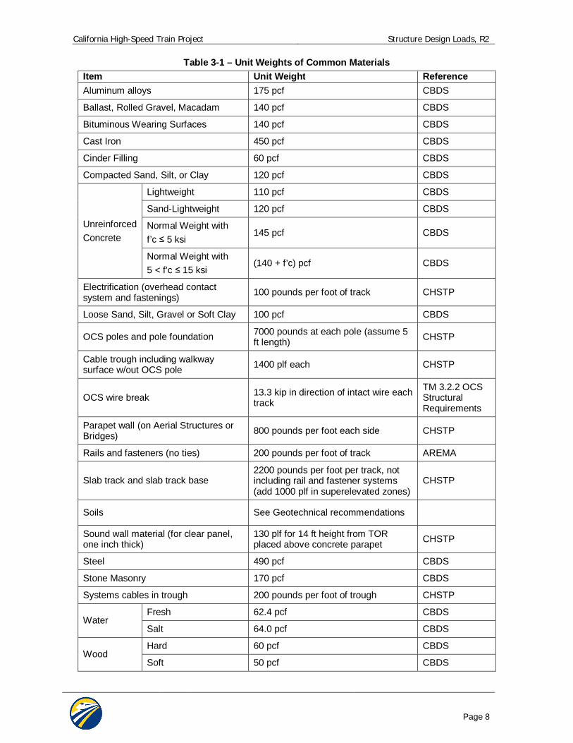
In the absence of more precise information, the unit weights specified in Table 3-1 may be used for dead loads.
DC refers to the dead load of structural components and permanent non-structural attachments supported by the structure including rails, rail fasteners, ballast, plinths, concrete cable troughs, parapet walls, sound walls, overhead contact system, etc.
DW refers to the dead load utilities attachments which may be non-permanent attachments.
If applicable, dead load shall be applied in stages to represent the sequence required to construct the structure. Analysis shall consider the effect of the maximum and minimum loading that may be imposed on the structure either during construction or resulting from future placement or removal of earth cover.
California High-Speed Train Project Structure Design Loads, R2
Page 8
Table 3-1 – Unit Weights of Common Materials Item Unit Weight Reference Aluminum alloys 175 pcf CBDS
Ballast, Rolled Gravel, Macadam 140 pcf CBDS
Bituminous Wearing Surfaces 140 pcf CBDS
Cast Iron 450 pcf CBDS
Cinder Filling 60 pcf CBDS
Compacted Sand, Silt, or Clay 120 pcf CBDS
Unreinforced Concrete
Lightweight 110 pcf CBDS
Sand-Lightweight 120 pcf CBDS
Normal Weight with f’c 5 ksi
145 pcf CBDS
Normal Weight with 5 < f’c 15 ksi
(140 + f’c) pcf CBDS
Electrification (overhead contact system and fastenings) 100 pounds per foot of track CHSTP
Loose Sand, Silt, Gravel or Soft Clay 100 pcf CBDS
OCS poles and pole foundation 7000 pounds at each pole (assume 5 ft length) CHSTP
Cable trough including walkway surface w/out OCS pole 1400 plf each CHSTP
OCS wire break 13.3 kip in direction of intact wire each track
TM 3.2.2 OCS Structural Requirements
Parapet wall (on Aerial Structures or Bridges) 800 pounds per foot each side CHSTP
Rails and fasteners (no ties) 200 pounds per foot of track AREMA
Slab track and slab track base 2200 pounds per foot per track, not including rail and fastener systems (add 1000 plf in superelevated zones)
CHSTP
Soils See Geotechnical recommendations
Sound wall material (for clear panel, one inch thick)
130 plf for 14 ft height from TOR placed above concrete parapet CHSTP
Steel 490 pcf CBDS
Stone Masonry 170 pcf CBDS
Systems cables in trough 200 pounds per foot of trough CHSTP
Water Fresh 62.4 pcf CBDS
Salt 64.0 pcf CBDS
Wood Hard 60 pcf CBDS
Soft 50 pcf CBDS
California High-Speed Train Project Structure Design Loads, R2
Page 9
3.4.2 Downdrag Force (DD) Possible development of downdrag on piles or shafts shall be considered. Recommended negative skin friction values shall be as provided for the particular site.. If specific design information is not available use CBDS 3.11.8.
3.4.3 Earth Pressures (EV, EH) Substructure elements and underground structures and earth retaining structures shall be proportioned to withstand earth pressure. Recommended soil parameters, earth pressures and loads due to surcharges shall be as provided for the particular site.
Vertical Earth Pressure (EV): Depth of cover shall be measured from the ground surface or roadway crown, or from the street grade, whichever is higher, to the top of the underground structure. Saturated densities of soils shall be used to determine the vertical earth pressure.
Lateral Static Earth Pressure (EH): For structures retaining draining cohesionless (granular) soil, lateral earth pressure shall be determined in accordance with the following paragraphs. For structures retaining other soil types, the lateral earth pressure shall follow the geotechnical recommendations.
Yielding Walls: Yielding walls (i.e.: typical cantilever retaining walls) are defined as walls which are unrestrained and free to move at the top for a distance of at least 0.004H, where H is defined as the height of the wall from the base of the heel to the finished grade directly above the heel.
For yielding walls, the lateral static earth pressure shall be determined using the active lateral pressures expressed as equivalent fluid pressures.
Rigid Walls: Rigid walls are defined as walls which are restrained at the top so that the amount of deflection required to develop active pressure conditions is not possible. All permanent excavation support walls as well as tunnel portal transitions and U-sections shall be considered as rigid walls.
For rigid walls, the static lateral soil pressure shall be determined using the at-rest lateral pressures expressed as equivalent fluid pressures.
Recommended geotechnical values shall be provided in the Geotechnical Reports. See TM 2.9.2 Geotechnical Reports Preparation Guidelines.
3.4.4 Earth Surcharge (ES) Surcharge loads (ES) are vertical or lateral loads resulting from loads applied above or below the adjacent ground surface. Procedures for determining surcharge load shall follow the geotechnical recommendations.
Underground structures and walls shall be designed for loading from existing adjacent buildings or structures. Consideration shall be given to the maximum and minimum loads that can be transferred to the design structure, and design loads shall be assumed to be the same as those for which the adjacent structure was designed. In the absence of this information, loads based on provisions in the CBC concurrent with the heaviest occupancy for which the building is suitable, shall be used.
Surcharge loads from adjacent buildings and structures commonly result from combinations of dead load, live load, etc. Due to this, surcharge loads applied for the design structure need not be factored twice, and shall be taken as the greater of the unfactored surcharge loading multiplied by the specified factor, ES, or the factored surcharge loading with ES equal to 1.0.
Structures that may support future developments above CHSTP facilities shall be designed to reflect the future load. Surcharge loads modeling future developments shall not be applied concurrently with traffic or future traffic surcharges in the same locations. If a future development extends to the surface land adjacent to an underground structure, then a surcharge shall be
California High-Speed Train Project Structure Design Loads, R2
Page 10
applied for design. The surcharge shall model the loading due to the maximum development currently allowed by zoning.
Construction activities may result in permanent or temporary loads from equipment, trucks, drayage, stockpiling of materials, or excavated earth. A surcharge shall be applied to all underground structures, unless: 1) positive and recognizable means are provided at the ground surface to ensure that the above types of loadings cannot occur; and, 2) the Authority specifically permits in writing, the application of a surcharge of lesser magnitude.
The vertical surcharge shall be considered as a static uniform load as follows:
600 psf, for h < 5 feet
600-40 (h-5) psf, for 5 feet h 20 feet
0 psf, for h > 20 feet
h = vertical distance from the top of structure to ground surface.
Surcharge loads representing construction activities need not be applied concurrently with traffic or future traffic surcharges in the same location.
See Subsection 3.5.1.7 Live Load Surcharge (LLS).
3.4.5 Earth Settlement Effects (SE) Earth settlement effects (SE) are forces or displacements imposed on a structure due to either uniform or differential settlement under sustained loading. Limiting values of settlement as given in the TM 2.9.10 Geotechnical Design Guidelines shall be used.
Tolerable settlement on foundations shall be developed by the structure designer consistent with the function and type of structure, fixity of bearings, anticipated service life, and consequences of unacceptable displacements on structural and operational performance.
At and near water crossings, scour potential should also be considered for earth settlement effects on shallow foundations.
3.4.6 Creep Effects (CR) For the effects due to creep of concrete (CR), the requirements in CBDS Section 5.4.2.3 shall be used.
3.4.7 Shrinkage Effects (SH) For the effects due to shrinkage of concrete (SH), the requirements in CBDS Section 5.4.2.3 shall be used.
3.4.8 Secondary Forces from Prestressing (PS) Secondary forces from prestressing (PS) shall be considered. Such secondary forces arise during prestress of statically indeterminate structures, which produce internal forces and support reactions. Secondary forces are generally obtained by subtracting the primary prestress forces from the total prestressing.
3.4.9 Locked-in Construction Forces (EL) Miscellaneous locked-in construction force effects (EL) resulting from the construction process shall be considered. Such effects include jacking apart adjacent cantilevers during segmental construction and bracing at excavation supports.
3.4.10 Water Loads (WA) The effects of ground water hydrostatic force, including static pressure of water, buoyancy, stream pressure, and wave loads (WA) shall be considered using the requirements in CBDS Section 3.7 and the recommended geotechnical values.
California High-Speed Train Project Structure Design Loads, R2
Page 11
The effects of ground water hydrostatic force, including buoyancy (WA) shall be considered in the design of underground structures and the substructure of aerial structures and buildings, including foundations and piling.
Adequate resistance to flotation shall be provided at all sections for full uplift pressure on the foundation, based upon the maximum probable height of the water table. For the completed structure, such resistance shall consist of the dead weight of the completed structure and the weight of backfill overlying the structure (within vertical planes drawn through the outer edges of the structure roof and through all joints).
Hydrostatic pressure shall normally be applied to all surfaces in contact with groundwater with a magnitude based on the depth of water and the applicable water density.
Changes in foundation condition due to scour shall be investigated per CBDS Article 3.7.5.
3.5 TRANSIENT LOADS 3.5.1 Live Loads (LLP, LLV, LLRR, LLH, LLS)
Live loads are due to high-speed trains, Cooper E-50 maintenance trains, Cooper E-80 freight trains, Amtrak Cooper E-80 passenger trains, Cooper E-80 engines pulling Metrolink and Caltrain passenger trains, highway loads, construction equipment, and pedestrians.
3.5.1.1 Floor, Roof, and Pedestrian Live Loads (LLP) For the force effects due to floor, roof, and pedestrian live loads (LLP), reference TM 2.5.1 Structural Design of Surface Facilities and Buildings. TM 2.5.1 includes provisions for aerial trackway supporting service walkways.
3.5.1.2 High-Speed Train Live Loads (LLV) The project specific rolling stock has not yet been determined. Once the project specific rolling stock is determined, the live load criteria will be expanded to consider these trains. Structures shall be designed to support the construction and maintenance trains described in 3.5.1.4.
Where a structure supports two or more tracks, the loading shall be applied for those number of tracks either simultaneously or individually, whichever governs design.
3.5.1.3 Shared Track Train Loads (LLRR) Structures that will support shared usage with another system shall be designed to support heavier rail loads than the maintenance and construction trains described in subsection 3.5.1.4. Typically other passenger rail systems have specific criteria. The other train design criteria shall be met in addition to the requirements presented herein for high-speed trains. Additionally, seismic design shall meet the requirements described in TM 2.10.4 Seismic Design and TM 2.10.10 Track Structure Interaction.
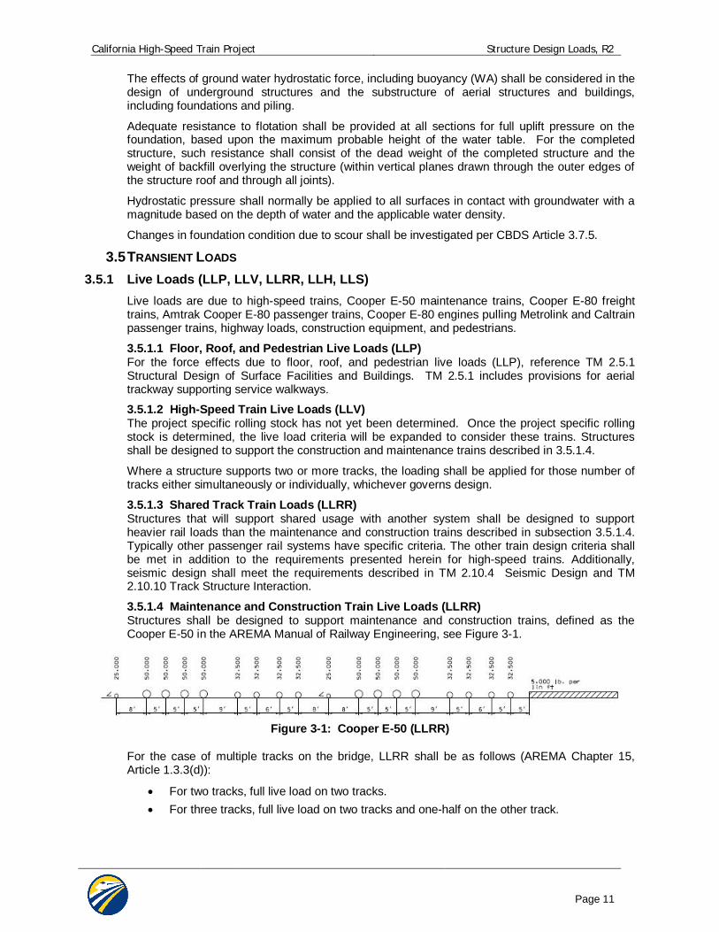
3.5.1.4 Maintenance and Construction Train Live Loads (LLRR) Structures shall be designed to support maintenance and construction trains, defined as the Cooper E-50 in the AREMA Manual of Railway Engineering, see Figure 3-1.
Figure 3-1: Cooper E-50 (LLRR)
For the case of multiple tracks on the bridge, LLRR shall be as follows (AREMA Chapter 15, Article 1.3.3(d)):
For two tracks, full live load on two tracks. For three tracks, full live load on two tracks and one-half on the other track.
California High-Speed Train Project Structure Design Loads, R2
Page 12
For four tracks, full live load on two tracks, one-half on one track, and one-quarter on the remaining one.
For more than four tracks, to be considered on an individual basis. The tracks selected for full live load shall be those tracks that will produce the most critical design condition on the member under consideration.
3.5.1.5 Amtrak Live Loads (LLRR) Segments of the alignment are required to be designed to provide for Amtrak service. These segments shall be designed to support Cooper E-50 trains as described in the AREMA Manual of Railway Engineering. The structure shall also meet all the requirements for structures supporting high-speed trains, including but not limited to track structure compatibility and the seismic requirements. These structures shall also be designed to resist two axles weighing 70 kips each, with a longitudinal spacing of 9.0 feet. This additional loading is required to account for local effects of Amtrak locomotives. 3.5.1.6 Highway Live Loads (LLH) Facilities designed to support highway loads (LLH) shall be designed for a minimum of HL-93 Truck Loading based on CBDS Section 3.6.1. For facilities that support highway permit loads, Caltrans guidelines shall be followed for the routing and sizes of the permit vehicles.
For underground structures beneath city streets or planned roadways including culverts, spread footings and pile caps, the distribution of live load shall be in accordance with the following:
Fill height less than two feet: Live load shall be applied as concentrated wheel loads directly to the top of the slab in addition to the uniform load specified in HL-93 loading.
Fill height greater than two feet: Concentrated wheel loads shall be distributed over the contact area, and increased by the depth of fill and added to the HL-93 uniform load.
When distribution areas overlap, the total load shall be uniformly distributed over an area defined by the outside limits of the individual areas.
The design lane load shall be distributed over that portion of a lane width as described in CBDS.
3.5.1.7 Live Load Surcharge (LLS) An area surcharge (LLS) shall be applied at the ground surface both over and adjacent to underground and retaining structures, as applicable, to account for presence of live load. Live load surcharge may result from presence of LLRR, LLV, LLH, possible future roadways, sidewalk live loads, or construction live loads.
Methods for lateral distribution of live load surcharge due to rail loading shall be in accordance with AREMA, Chapter 8, Article 5.3.1 and 16.4.3. Lateral distribution of highway surcharge shall be in accordance with CBDS, Article 3.6.1.2.6. No impact factors apply to LLS for walls. Buried components shall be subject to impact as follows:
%0)125.00.1(*)( DIburiedI
Where:
I = impact in accordance with Article 3.5.2, herein
D = minimum depth of earth cover above structure (ft)
Recommended coefficients for lateral surcharge loading shall be used.
3.5.1.8 Live Loads for Fatigue Assessment For structures carrying high-speed trains, the project specific rolling stock (LLV) plus impact (I) shall be used for fatigue assessment of all structures. The methods of CBDS Subsection 3.6.1.4 shall be used to evaluate fatigue loads.
The fatigue assessment shall be performed for all structural elements which are subjected to fluctuations of stress. For structures supporting multiple tracks, the loading shall be applied to a minimum of two (2) tracks in the most unfavorable positions. The fatigue damage shall be
California High-Speed Train Project Structure Design Loads, R2
Page 13
assessed over the required structural life of 100 years. During maximum service condition of 12 trains per hour, 20 hours service/day and 32 axles per train there are 2.8 million axle loads per track per year.
3.5.2 Vertical Impact Effect (IM) Moving trains and vehicles impart dynamic load to bridges, which are considered through a dynamic coefficient or impact factor. The static effects of the design train loads, other than centrifugal force, traction, braking, nosing and hunting shall be increased by the percentages specified.
Impact applies to the following:
1. Superstructures, including steel or concrete supporting columns, steel towers, legs of rigid frames, and generally those portions of the structure which extend down to the main foundation.
2. The portion above the ground line of concrete or steel piles that support the superstructure directly.
Impact does not apply to the following: 1. Retaining walls, wall-type piers, and piles except those described above. 2. Foundations and footings entirely below ground, and base slabs which are in direct
contact with earth. 3. Floor, roof, and pedestrian live loads (LLP).
For LLRR
Static impact factors (IM) for LLRR shall be taken from AREMA and Eurocode Specifications.
Ballasted track:
Reinforced or prestressed concrete bridges: (AREMA Chapter 8, Article 2.2.3(d)):
%60IM where L < 14 feet
LIM 225 where 14 feet < L 127 feet
%20IM where L > 127 feet
Steel bridges (AREMA Chapter 15, 1.3.5(c)):
1600340
2LIM where L < 80 feet
3060016
LIM where L 80 feet
For direct fixation on concrete slab track with spans less than 40 feet, European Standard EN 1991-2 shall be used as modified below. For longer spans, AREMA ballasted track impact factors shall be used as a lower bound.
For direct fixation on concrete slab track:
%10027.02.0305.0
16.2100L
IM where L 40 ft
L = span length for member under consideration (i.e., main girder, bridge deck, etc.)
The calculated value shall be applied at top of rail as a percentage of live load.
California High-Speed Train Project Structure Design Loads, R2
Page 14
An additional ±20% imbalance of live load shall be applied to each rail as a vertical force to model the couple caused by rocking of the train. The couple shall be applied on each track in the direction which will produce the most unfavorable effect in the member under consideration.
For LLV
Dynamic analysis is required for structures carrying high-speed trains (LLV) in sites with speeds greater than 200 mph in order to determine impact effects.
For more dynamic analysis requirements, see TM 2.10.10 Track Structure Interaction.
For LLH
Section 3.6.2 shall be used for determining impact factors (IM) associated with highway loading (LLH), CBDS Dynamic Load Allowance (IM).
3.5.3 Centrifugal Force (CF) For structures carrying high-speed trains on a curved alignment, centrifugal force (CF) shall be considered. Multiple presence factors may apply to centrifugal forces.
For LLRR and LLV
The centrifugal force (CF) is a function of the axle weights of the train live load (LLRR or LLV), train speed, and horizontal radius of curvature.
For LLRR, CF acts at 8 feet above top of rail.
For LLV, CF acts at 6 feet above top of rail.
CF = (LLRR or LLV) x [0.0668*V2 *f /R]
V = train speed (mph)
R = horizontal radius of curvature (ft)
f = reduction factor, not to be taken less than 0.35:
f = 1, for LLRR, for V 75 mph
f = 1 - [(V - 75)/621.4] x [506/V + 1.75] x [1 - (9.45/ L)1/2] 0.35, for LLRR, V > 75 mph
f = 1, for LLV, all speeds
L = length in feet of the loaded portion of curved track on the bridge.
If the maximum line speed at the site is in excess of 75 mph, the centrifugal force shall be investigated at 75 mph with a reduction factor of 1.0, and at the maximum line speed with a reduction factor less than 1.0.
The effect of superelevation shall be considered when present. The superelevation effect shifts the centroid of the train laterally producing an unequal transverse distribution between rails. Consideration shall be given to the cases in which the train is moving and in the at rest condition.
LLH
For structures carrying highway loads on a curved alignment, centrifugal force (CF) shall be per CBDS Section 3.6.3.
3.5.4 Traction and Braking Forces (LF) For LLRR
For traction and braking forces (LF) from passenger trains, freight trains, maintenance and construction trains (LLRR) use AREMA Article 2.2.3:
Traction force = N(25 L) kips, acting 3 feet above top of rail
Braking force = N(45 + 1.2L) kips, acting 8 feet above top of rail
California High-Speed Train Project Structure Design Loads, R2
Page 15
Where:
L = length in feet of portion of bridge under consideration
N = ratio of Cooper train load to Cooper E80 loading for the sizes of trains that will use the structure (i.e., for Cooper E50, N = 0.625)
The LF loads for LLRR are to be distributed equally over the length of the train. Multiple presence factors shall apply.
For LLV
For traction and braking forces (LF) from high-speed trains (LLV) shall be:
Traction force = 2.26L (kips) or 25% of train load (if known), with a maximum value of 225 kips, acting at top of rail
Braking force = 1.37L (kips) or 25% of train load (if known), with a maximum value of 1350 kips, acting at top of rail
where L = length in feet of portion of bridge under consideration.
These loads are to be distributed equally to all axles over the length of the train.
Note that traction and braking forces will be reviewed and possibly revised when project-specific rolling stock is selected.
For dynamic analyses of the longitudinal distribution of the traction and braking forces (LF) from high-speed trains through the rails and rail fasteners to the track slabs on the decks to the substructures shall follow the recommendations in TM 2.10.10 Track Structure Interaction.
For LLH
For braking forces (LF) from highway loading (LLH), CBDS Section 3.6.4 shall be used.
3.5.5 Nosing and Hunting Effects (NE) For LLRR and LLH
Nosing and hunting effects do not apply to LLRR and LLH.
For LLV
For structures carrying high-speed trains with slab track and direct fixation fasteners, nosing and hunting effects (NE) of the wheels contacting the rails shall be accounted for by an 11 kip force per axle applied to the top of the low rail, perpendicular to the track centerline, acting horizontal at the most unfavorable position.
NE is not applicable for the design of structures with ballasted track.
NE shall be applied simultaneously with centrifugal force (CF).
3.5.6 Wind Loads (WS, WL) For LLRR and LLV
Wind Pressure on Structures (WS) and Wind Pressure on Trains (WL) shall be calculated in accordance with requirements in CBDS Section 3.8 with the following modifications:
(1) The effective wind area shall include the exposed area of all bridge elements, OCS poles, and catenary. For parapets and barriers, shielding of downwind elements from those upwind shall not be considered (i.e. the exposed area shall include the summation of all parapets of significant height contained on the bridge).
(2) Use of “Suburban” and “City” exposure categories to calculate design wind velocity is discouraged and shall be accepted only on a case-by-case basis.
(3) The base lateral load for Wind Pressure on Vehicles (WL) shall be revised to 0.300 klf perpendicular to the train acting 8 feet above the top of rail. CBDS Table 3.8.1.3-1 Wind
California High-Speed Train Project Structure Design Loads, R2
Page 16
Components on Live Load for skewed angles of incidence shall be revised proportionally to reflect the modified base lateral load.
(4) For structures which utilize soundwalls or windwalls capable of effectively shielding the train from wind loading, consideration may be given to a reduction of WL. The reduction may be taken as the fractional height of train which is shielded by the wall, assuming the train to be 14 feet tall with a lower border at 1 foot from top of rail. However this reduction shall not exceed 50% of WL.
Local design of elements such as parapets or components on structures shall give consideration to wind loading and slipstream effects. Wind loading on these elements may be calculated per applicable building code, as detailed in TM 2.5.1 Structural Design of Surface Facilities and Buildings. The wind importance factor shall equal 1.15.
Wind loading for non-conventional bridge types or long-spans will require special attention (e.g., aerodynamic effects). For LLH
Wind loads (WS, WL) on highway structures and vehicles shall be per CBDS Section 3.8.
3.5.7 Slipstream Effects (SS) For LLV
3.5.7.1 Aerodynamic Actions from Passing Trains The passing of high-speed trains subjects any structure situated near the track to transient pressure waves. This action may be approximated by equivalent loads acting at the front and rear of the train.
Aerodynamic actions from passing trains shall be taken into account when designing structures adjacent to railway tracks.
The passing of rail traffic subjects any structure situated near the track to a traveling wave of alternating pressure and suction (see Figures 3-2 to 3-7). The magnitude of the action depends mainly on: - square of the speed of the train - aerodynamic shape of the train - shape of the structure - position of the structure, particularly the clearance between the vehicle and the
structure The actions may be approximated by equivalent loads at the ends of a train, when
checking ultimate and serviceability limit states and fatigue. Equivalent loads are given in Sections 3.5.7.2 to 3.5.7.6.
In Sections 3.5.7.2 to 3.5.7.6 the Maximum Design Speed V [mph] should be taken as the Maximum Line Speed at the site.
At the start and end of structures adjacent to the tracks, for a length of 16.4 feet from the start and end of the structure measured parallel to the tracks, the equivalent loads in Sections 3.5.7.2 to 3.5.7.6 should be multiplied by a dynamic amplification factor of 2.0.
NOTE: For dynamically sensitive structures the above dynamic amplification factor may be insufficient and may need to be determined by a special study. The study should take into account dynamic characteristics of the structure including support and end conditions, the speed of the adjacent rail traffic and associated aerodynamic actions and the dynamic response of the structure including the speed of a deflection wave induced in the structure. In addition, for dynamically sensitive structures a dynamic amplification factor may be necessary for parts of the structure between the start and end of the structure.
California High-Speed Train Project Structure Design Loads, R2
Page 17
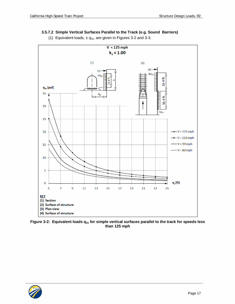
3.5.7.2 Simple Vertical Surfaces Parallel to the Track (e.g. Sound Barriers) (1) Equivalent loads, ± q1k, are given in Figures 3-2 and 3-3.
Figure 3-2: Equivalent loads q1k for simple vertical surfaces parallel to the track for speeds less
than 125 mph
California High-Speed Train Project Structure Design Loads, R2
Page 18
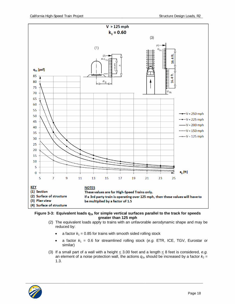
Figure 3-3: Equivalent loads q1k for simple vertical surfaces parallel to the track for speeds
greater than 125 mph (2) The equivalent loads apply to trains with an unfavorable aerodynamic shape and may be
reduced by:
a factor k1 = 0.85 for trains with smooth sided rolling stock
a factor k1 = 0.6 for streamlined rolling stock (e.g. ETR, ICE, TGV, Eurostar or similar)
(3) If a small part of a wall with a height < 3.00 feet and a length < 8 feet is considered, e.g. an element of a noise protection wall, the actions q1k should be increased by a factor k2 = 1.3.
California High-Speed Train Project Structure Design Loads, R2
Page 19
(4) For surfaces perpendicular to the train, the actions q1k shall be taken from figures 3-2 and 3-3 for the distance indicated from track centerline modified as described in the previous items.
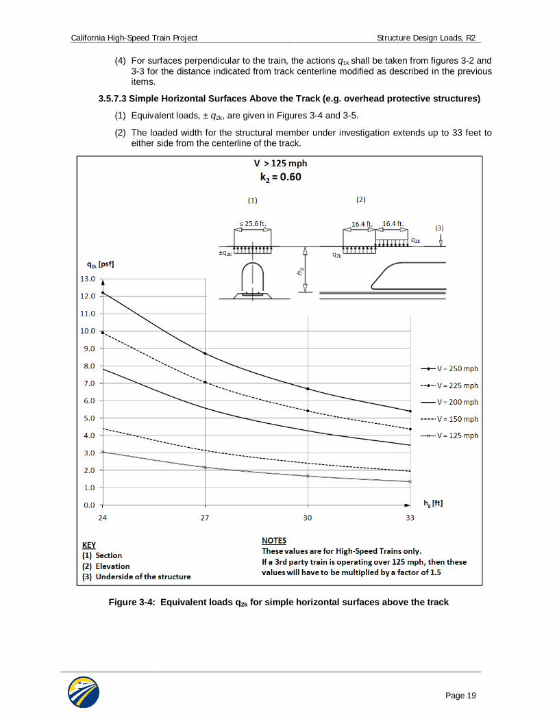
3.5.7.3 Simple Horizontal Surfaces Above the Track (e.g. overhead protective structures)
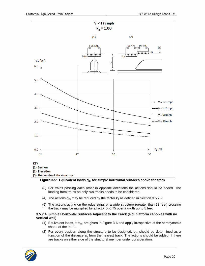
(1) Equivalent loads, ± q2k, are given in Figures 3-4 and 3-5.
(2) The loaded width for the structural member under investigation extends up to 33 feet to either side from the centerline of the track.
Figure 3-4: Equivalent loads q2k for simple horizontal surfaces above the track
California High-Speed Train Project Structure Design Loads, R2
Page 20
Figure 3-5: Equivalent loads q2k for simple horizontal surfaces above the track
(3) For trains passing each other in opposite directions the actions should be added. The loading from trains on only two tracks needs to be considered.
(4) The actions q2k may be reduced by the factor k1 as defined in Section 3.5.7.2.
(5) The actions acting on the edge strips of a wide structure (greater than 33 feet) crossing the track may be multiplied by a factor of 0.75 over a width up to 5 feet.
3.5.7.4 Simple Horizontal Surfaces Adjacent to the Track (e.g. platform canopies with no vertical wall)
(1) Equivalent loads, ± q3k, are given in Figure 3-6 and apply irrespective of the aerodynamic shape of the train.
(2) For every position along the structure to be designed, q3k should be determined as a function of the distance ag from the nearest track. The actions should be added, if there are tracks on either side of the structural member under consideration.
California High-Speed Train Project Structure Design Loads, R2
Page 21
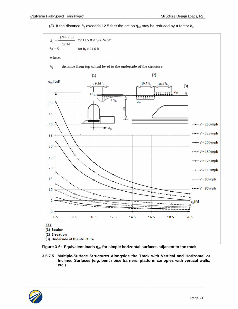
(3) If the distance hg exceeds 12.5 feet the action q3k may be reduced by a factor k3.
Figure 3-6: Equivalent loads q3k for simple horizontal surfaces adjacent to the track
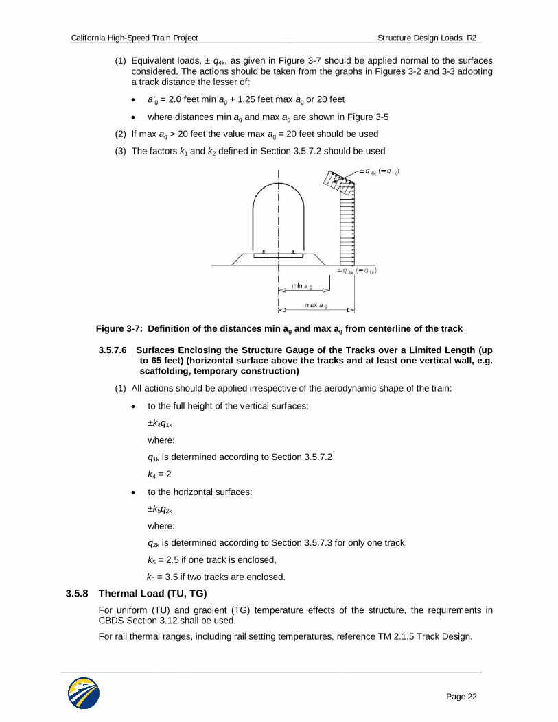
3.5.7.5 Multiple-Surface Structures Alongside the Track with Vertical and Horizontal or Inclined Surfaces (e.g. bent noise barriers, platform canopies with vertical walls, etc.)
California High-Speed Train Project Structure Design Loads, R2
Page 22
(1) Equivalent loads, ± q4k, as given in Figure 3-7 should be applied normal to the surfaces considered. The actions should be taken from the graphs in Figures 3-2 and 3-3 adopting a track distance the lesser of:
a'g = 2.0 feet min ag + 1.25 feet max ag or 20 feet
where distances min ag and max ag are shown in Figure 3-5
(2) If max ag > 20 feet the value max ag = 20 feet should be used
(3) The factors k1 and k2 defined in Section 3.5.7.2 should be used
Figure 3-7: Definition of the distances min ag and max ag from centerline of the track
3.5.7.6 Surfaces Enclosing the Structure Gauge of the Tracks over a Limited Length (up to 65 feet) (horizontal surface above the tracks and at least one vertical wall, e.g. scaffolding, temporary construction)
(1) All actions should be applied irrespective of the aerodynamic shape of the train:
to the full height of the vertical surfaces:
±k4q1k
where:
q1k is determined according to Section 3.5.7.2
k4 = 2
to the horizontal surfaces:
±k5q2k
where:
q2k is determined according to Section 3.5.7.3 for only one track,
k5 = 2.5 if one track is enclosed,
k5 = 3.5 if two tracks are enclosed.
3.5.8 Thermal Load (TU, TG) For uniform (TU) and gradient (TG) temperature effects of the structure, the requirements in CBDS Section 3.12 shall be used.
For rail thermal ranges, including rail setting temperatures, reference TM 2.1.5 Track Design.
California High-Speed Train Project Structure Design Loads, R2
Page 23
3.5.9 Frictional Force (FR) The force due to friction (FR) shall be established on the basis of extreme values of the friction coefficient between sliding surfaces (i.e.: at bearing pads). Where appropriate, the effects of moisture, degradation, and contamination of sliding or rotating surfaces upon the friction coefficient shall be considered. For further guidance see CBDS 3.13.
3.5.10 Seismic Loads (MCE, OBE) Detailed, project specific seismic design criteria are presented in TM 2.10.4 Seismic Design Criteria. TM 2.10.4 defines seismic design philosophies, seismic analysis/demand methodologies, and structural capacity evaluation procedures for the multiple levels of design earthquakes.
In general, an individual structure may need to comply with multiple performance levels, depending upon its Importance and Technical Classification.
Highway bridges or structures spanning over high-speed train trackways, or highway structures which have the capacity to influence operability of high-speed trains in event of a failure, shall be designed for the seismic requirements per provisions in TM 2.10.4 Seismic Criteria in addition to Caltrans Seismic Design Criteria (CSDC).
3.5.11 Hydrodynamic Force (WAD) Hydrodynamic pressure effects acting on submerged portions of structures due to seismic motion shall be computed using the method of Goyal and Chopra [12] or by equivalent means.
For possible additional hydrodynamic force effects, see the Geotechnical Design Report.
3.5.12 Dynamic Earth Pressures (ED) Dynamic earth pressure due to seismic motion on retaining structures shall be computed using the methods described in the Geotechnical Design Report.
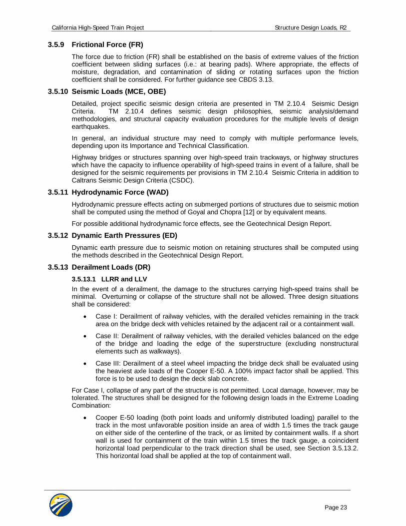
3.5.13 Derailment Loads (DR) 3.5.13.1 LLRR and LLV In the event of a derailment, the damage to the structures carrying high-speed trains shall be minimal. Overturning or collapse of the structure shall not be allowed. Three design situations shall be considered:
Case I: Derailment of railway vehicles, with the derailed vehicles remaining in the track area on the bridge deck with vehicles retained by the adjacent rail or a containment wall.
Case II: Derailment of railway vehicles, with the derailed vehicles balanced on the edge of the bridge and loading the edge of the superstructure (excluding nonstructural elements such as walkways).
Case III: Derailment of a steel wheel impacting the bridge deck shall be evaluated using the heaviest axle loads of the Cooper E-50. A 100% impact factor shall be applied. This force is to be used to design the deck slab concrete.
For Case I, collapse of any part of the structure is not permitted. Local damage, however, may be tolerated. The structures shall be designed for the following design loads in the Extreme Loading Combination:
Cooper E-50 loading (both point loads and uniformly distributed loading) parallel to the track in the most unfavorable position inside an area of width 1.5 times the track gauge on either side of the centerline of the track, or as limited by containment walls. If a short wall is used for containment of the train within 1.5 times the track gauge, a coincident horizontal load perpendicular to the track direction shall be used, see Section 3.5.13.2. This horizontal load shall be applied at the top of containment wall.
California High-Speed Train Project Structure Design Loads, R2
Page 24
Figure 3-8: Derailment Case I
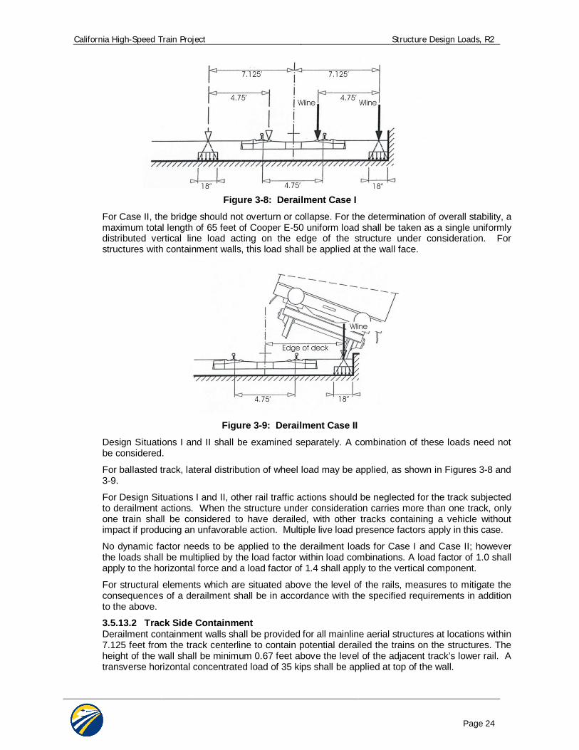
For Case II, the bridge should not overturn or collapse. For the determination of overall stability, a maximum total length of 65 feet of Cooper E-50 uniform load shall be taken as a single uniformly distributed vertical line load acting on the edge of the structure under consideration. For structures with containment walls, this load shall be applied at the wall face.
Figure 3-9: Derailment Case II
Design Situations I and II shall be examined separately. A combination of these loads need not be considered.
For ballasted track, lateral distribution of wheel load may be applied, as shown in Figures 3-8 and 3-9.
For Design Situations I and II, other rail traffic actions should be neglected for the track subjected to derailment actions. When the structure under consideration carries more than one track, only one train shall be considered to have derailed, with other tracks containing a vehicle without impact if producing an unfavorable action. Multiple live load presence factors apply in this case.
No dynamic factor needs to be applied to the derailment loads for Case I and Case II; however the loads shall be multiplied by the load factor within load combinations. A load factor of 1.0 shall apply to the horizontal force and a load factor of 1.4 shall apply to the vertical component.
For structural elements which are situated above the level of the rails, measures to mitigate the consequences of a derailment shall be in accordance with the specified requirements in addition to the above.
3.5.13.2 Track Side Containment Derailment containment walls shall be provided for all mainline aerial structures at locations within 7.125 feet from the track centerline to contain potential derailed the trains on the structures. The height of the wall shall be minimum 0.67 feet above the level of the adjacent track’s lower rail. A transverse horizontal concentrated load of 35 kips shall be applied at top of the wall.
California High-Speed Train Project Structure Design Loads, R2
Page 25
3.5.14 Collision Loads (CL) Collision loads in Subsections 3.5.14.1 to 3.5.14.2 apply to train impact loads (LLRR, LLV). Section 3.5.14.3 applies to highway collision loads (LLH). For collision loads on columns or divider walls along the trackway, refer to TM 2.5.1 Structural Design of Surface Facilities and Buildings. 3.5.14.1 Collision Loads other than at Stations or Platforms Unprotected members within 16.5 feet of the track centerline shall be designed to resist train collision, 900 kips parallel to track, or 350 kips perpendicular to tracks applied at platform level.
3.5.14.2 Structures in Areas beyond Track Ends (1) Overrunning of rail traffic beyond the end of a track or tracks (for example at a terminal
station) should be taken into account as an accidental design situation when the structure or its supports are located in the area immediately beyond the track ends.
(2) The measures to manage the risk should be based on the utilization of the area immediately beyond the track end and take into account any measures taken to reduce the likelihood of an overrun of rail traffic.
(3) Supporting structural members to structures should generally not be located in the area immediately beyond the track ends.
(4) Where supporting structural members are required to be located near to track ends, an end impact wall should be provided in the area immediately beyond the track ends in addition to any buffer stop.
The design values for the static equivalent force due to impact on the end impact wall are Fdx = 1125 kips for passenger trains and Fdx = 2250 kips for freight trains or heavy engines pulling conventional passenger or freight. It is recommended that these forces are applied horizontally at a level of 3 feet above track level.
3.5.14.3 Highway Vehicle Collision Loads (LLH) Highway collision loading shall be as per CBDS Section 3.6.5.
3.6 MISCELLANEOUS LOADS 3.6.1 Overhead Contact System (OCS) Loads
Design loads of OCS pole foundations shall be in accordance with TM 3.2.2 OCS Structural Requirements.
Catenary pole foundations shall be capacity-protected to prevent failure or unrecoverable damage to the bridge deck.
Aerial trackway structures shall be designed in such a manner that the OCS pole foundation locations can be determined at a later time.
3.6.2 Construction Loads and Temporary Structures 3.6.2.1 Temporary Structure Classification Temporary structures are divided into the following classifications:
Type A: Temporary structures or structures under temporary conditions which carry or will carry high-speed trains and/or pass over routes carrying high-speed trains. Subsequent articles herein apply to Type A structures.
Type B: Temporary structures or structures under temporary conditions which do not carry high-speed trains and do not pass over routes carrying high-speed trains. These structures shall be designed in accordance with the specifications of the owner or operating agency (e.g. Caltrans: CBDS and CMTD). Structures such as haul bridges used temporarily for the CHSRP shall be designed in accordance with CMTD 15-14.
California High-Speed Train Project Structure Design Loads, R2
Page 26
3.6.2.2 Construction Load Combinations Temporary structures or structures under temporary conditions shall be designed to adequately resist conditions at all stages of construction, including all applicable construction loads. Construction load combinations shall include the following:
Applicable strength load combinations: Dead load factors shall not be taken less than 1.25, with construction dead loads taken as permanent loads. Construction transient live load factors shall not be taken less than 1.5. Wind load factors may be reduced by 20%.
Service 1, as applicable.
Seismic load combinations: For 30% design, Load Combination Extreme 3, with revised ground motions having 10% probability of exceedance in 10 years. Performance criteria shall comply with the No Collapse Level (NCL) for an important, standard structure, see TM 2.10.4 Seismic Design Criteria. If significant construction loads are anticipated or specialized equipment present, this mass shall be accounted for in the seismic design.
In the absence of better criteria, a construction live load of 20 psf shall be assumed on the bridge deck.
3.6.2.3 Segmental Construction and Specialized Equipment Construction load combinations per CBDS Article 5.14.2 “Segmental Construction” shall be considered. The temporary seismic load event as described above shall be added to the construction load combination at strength limit states; however a 1.25 load factor may be used for dead and live loads. The temporary seismic event need not be combined with the dynamic construction load impact due to segment drop or equipment impact. For balanced cantilever construction methods an additional 2% of dead load shall be applied to reflect eccentric conditions at the time of a potential seismic event. Single complete span precast girders may be transported to the erection site on top of previously erected girders using specialty heavy load transporters. If this construction method is used then girders shall be designed to support the wheel loads from the transporter. Load factors shall be as described in the previous paragraph.
3.6.3 Rail-Structure Interaction Forces Effects of continuous welded rail (CWR) interaction with the structure through its attachment shall be considered. Design guidance for this interaction is provided in TM 2.10.10 Track Structure Interaction.
Interaction effects of the CWR and structure result after connection of the rail to the structure. These occur in large part due to the following: temperature variations in the rail and structure, braking/traction, creep and shrinkage, and seismic events. Load combinations presented in this document assume this interaction implicit to each load within the combination, with associated load factors.
Structure thermal ranges shall be calculated per provisions in this document. For specific rail information, including thermal ranges, setting temperature, and rail section, refer to TM 2.1.5 Track Design.
TM 2.10.10 Track Structure Interaction also addresses rail-structure interaction under seismic events, including performance objectives and design methodology.
3.6.4 Blast Loading Blast loadings and measures to mitigate are not specified at this time.
California High-Speed Train Project Structure Design Loads, R2
Page 27
3.7 LOAD FACTORS AND LOAD MODIFIERS For structures carrying high-speed trains, the design shall be in accordance with CBDS Section 1.3.2:
i i Qi Rn = Rr Where:
i = load factor applied to force effects (see Tables 3-2, 3-3, and 3-4)
= resistance factor applied to minimal resistance (see Table 3-5)
i = load modifier relating to ductility, redundancy and importance (CBDS, section 1.3.2)
Qi = force effect
Rn = nominal resistance
Rr = factored resistance, Rn
For loads in which a maximum value of “ i” produces an unfavorable action, the value of “ i” shall be equal to 1.05 to account for the 100 year design life of the facility. The load modifier is based upon AASHTO LRFD Article 1.3.2, and is applicable to Strength Limit Load Combinations only.
Variation of load factors for permanent loads, p, are presented in Table 3-3 and 3-4.
Some selected resistance factors “ ” are presented in Table 3-5.
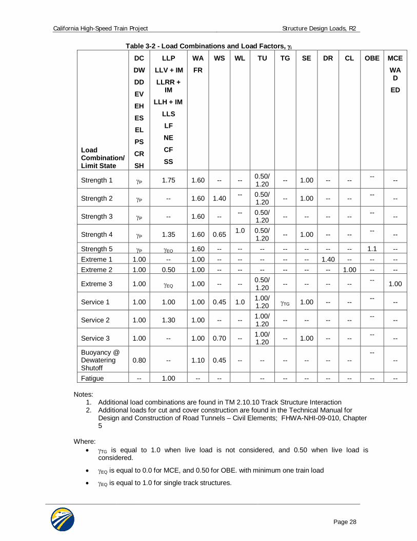
3.7.1 Design Load Combinations The load combinations to be used for structures carrying high-speed trains are presented in Table 3-2. The descriptions of the load combinations are as follows:
”Strength 1” is the basic load combination for normal use. ”Strength 2” is the load combination for the structure exposed to wind. “Strength 3” is the load combination for very high dead load to live load force effect ratios. “Strength 4” is the load combination for normal use when exposed to wind. “Strength 5” is the load combination for normal use when designing columns for Operating
Basis seismic events, (OBE). “Extreme 1” is the load combination for derailment. “Extreme 2” is the load combination for collision. “Extreme 3” is the load combination for Extreme seismic events: Maximum Considered
Earthquake (MCE), ”Service 1” is the basic service load combination for normal use with wind. ”Service 2” is the service load combination intended to control yielding of steel structures and
slip of slip-critical connections due to train load. ”Service 3” is the service load combination relating only to tension in prestressed concrete
columns with the objective of crack control. “Buoyancy at Dewatering Shutoff” is a service load for evaluation of uplift with a minimum
weight structure. “Fatigue” is the fatigue and fracture load combination relating to repetitive train loading.
Note that for each load combination shown below, all physically achievable subsets (i.e., omitting load factors by setting i = 0) which may govern design shall be considered.
Note that other load cases for train and track structure interaction are contained within TM 2.10.10 Track Structure Interaction.
California High-Speed Train Project Structure Design Loads, R2
Page 28
Table 3-2 - Load Combinations and Load Factors, i
Load Combination/ Limit State
DC
DW
DD
EV
EH
ES EL
PS
CR
SH
LLP
LLV + IM
LLRR + IM
LLH + IM
LLS LF
NE
CF
SS
WA
FR
WS WL
TU TG SE DR CL OBE MCE
WAD
ED
Strength 1 P 1.75 1.60 -- -- 0.50/1.20 -- 1.00 -- -- -- --
Strength 2 P -- 1.60 1.40 -- 0.50/1.20 -- 1.00 -- -- -- --
Strength 3 P -- 1.60 -- -- 0.50/1.20 -- -- -- -- -- --
Strength 4 P 1.35 1.60 0.65 1.0 0.50/1.20 -- 1.00 -- -- -- --
Strength 5 P EQ 1.60 -- -- -- -- -- -- -- 1.1 -- Extreme 1 1.00 -- 1.00 -- -- -- -- -- 1.40 -- -- -- Extreme 2 1.00 0.50 1.00 -- -- -- -- -- -- 1.00 -- --
Extreme 3 1.00 EQ 1.00 -- -- 0.50/1.20 -- -- -- -- -- 1.00
Service 1 1.00 1.00 1.00 0.45 1.0 1.00/1.20 TG 1.00 -- -- -- --
Service 2 1.00 1.30 1.00 -- -- 1.00/1.20 -- -- -- -- -- --
Service 3 1.00 -- 1.00 0.70 -- 1.00/1.20 -- 1.00 -- -- -- --
Buoyancy @ Dewatering Shutoff
0.80 -- 1.10 0.45 -- -- -- -- -- -- --
--
Fatigue -- 1.00 -- -- -- -- -- -- -- -- -- Notes:
1. Additional load combinations are found in TM 2.10.10 Track Structure Interaction 2. Additional loads for cut and cover construction are found in the Technical Manual for
Design and Construction of Road Tunnels – Civil Elements; FHWA-NHI-09-010, Chapter 5
Where:
TG is equal to 1.0 when live load is not considered, and 0.50 when live load is considered.
EQ is equal to 0.0 for MCE, and 0.50 for OBE. with minimum one train load
EQ is equal to 1.0 for single track structures.
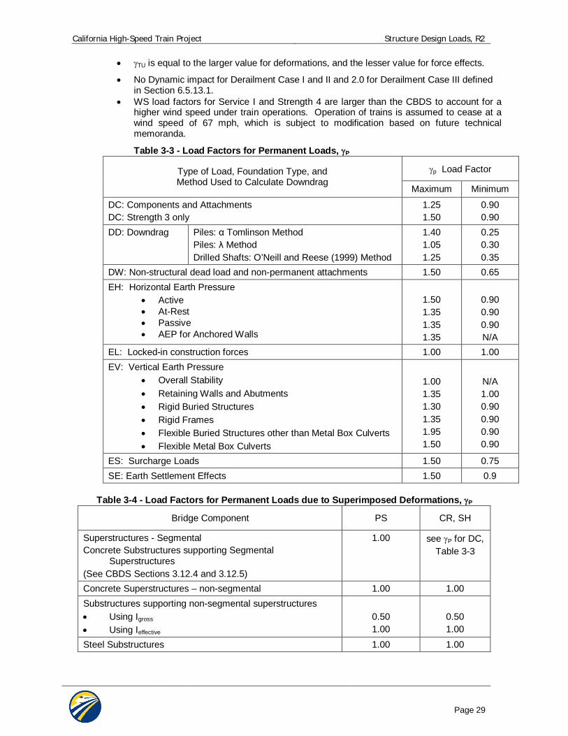
California High-Speed Train Project Structure Design Loads, R2
Page 29
TU is equal to the larger value for deformations, and the lesser value for force effects.
No Dynamic impact for Derailment Case I and II and 2.0 for Derailment Case III defined in Section 6.5.13.1.
WS load factors for Service I and Strength 4 are larger than the CBDS to account for a higher wind speed under train operations. Operation of trains is assumed to cease at a wind speed of 67 mph, which is subject to modification based on future technical memoranda.
Table 3-3 - Load Factors for Permanent Loads, P
Type of Load, Foundation Type, and Method Used to Calculate Downdrag
p Load Factor
Maximum Minimum
DC: Components and Attachments DC: Strength 3 only
1.25 1.50
0.90 0.90
DD: Downdrag Piles: Tomlinson Method Piles: Method Drilled Shafts: O’Neill and Reese (1999) Method
1.40 1.05 1.25
0.25 0.30 0.35
DW: Non-structural dead load and non-permanent attachments 1.50 0.65 EH: Horizontal Earth Pressure
Active At-Rest Passive AEP for Anchored Walls
1.50 1.35 1.35 1.35
0.90 0.90 0.90 N/A
EL: Locked-in construction forces 1.00 1.00 EV: Vertical Earth Pressure
Overall Stability Retaining Walls and Abutments Rigid Buried Structures Rigid Frames Flexible Buried Structures other than Metal Box Culverts Flexible Metal Box Culverts
1.00 1.35 1.30 1.35 1.95 1.50
N/A 1.00 0.90 0.90 0.90 0.90
ES: Surcharge Loads 1.50 0.75 SE: Earth Settlement Effects 1.50 0.9
Table 3-4 - Load Factors for Permanent Loads due to Superimposed Deformations, P
Bridge Component PS CR, SH
Superstructures - Segmental Concrete Substructures supporting Segmental
Superstructures (See CBDS Sections 3.12.4 and 3.12.5)
1.00 see P for DC, Table 3-3
Concrete Superstructures – non-segmental 1.00 1.00 Substructures supporting non-segmental superstructures Using Igross Using Ieffective
0.50 1.00
0.50 1.00
Steel Substructures 1.00 1.00
California High-Speed Train Project Structure Design Loads, R2
Page 30
Permanent Loads: DC: dead load of structural components and permanent attachments DW: dead load of non-structural and non-permanent attachments DD: downdrag force EV: vertical earth pressure from dead load of earth fill EH: lateral static earth pressure ES: surcharge loads SE: earth settlement effects EL: accumulated locked-in force effects resulting from the construction process. PS: secondary forces from post-tensioning CR: creep effects SH: shrinkage effects WA: water loads
Transient Loads: LLP: floor, roof, and pedestrian live loads LLV: high-speed train live loads LLRR maintenance and construction train live loads LLH: highway live loads LLS: live load surcharge IM: vertical dynamic impact effect LF: traction or braking forces NE: nosing and hunting effects CF: centrifugal force DR: derailment loads CL: collision loads WS: wind load on structure WL: wind load on live load SS: slipstream effects TU: uniform temperature effects TG: gradient temperature effects FR: frictional force MCE: Maximum Considered Earthquake OBE: Operating Basis Earthquake WAD: hydrodynamic force ED: dynamic earth pressures

California High-Speed Train Project Structure Design Loads, R2
Page 31
3.7.2 Resistance Factors Selected resistance factors , with CBDS reference, are listed in Table 3-5.
Table 3-5 Selected Resistance Factors, Description
Factor
CBDS Reference
Tension controlled reinforced concrete 0.90 5.5.4.2 Tension controlled prestressed concrete 1.00 5.5.4.2 Shear and torsion, normal weight concrete 0.90 5.5.4.2 Compression controlled sections with spirals or ties 0.75 5.5.4.2 Bearing on concrete 0.70 5.5.4.2 Flexure or shear on structural steel 1.00 6.5.4.2 Axial compression in structural steel 0.90 6.5.4.2 Axial tension, yielding of gross section in structural steel 0.95 6.5.4.2 A325 and A490 bolts in shear or tension 0.80 6.5.4.2 Aluminum in tension, ultimate 0.90 7.5.4 Aluminum in tension, yield 0.75 7.5.4 Aluminum in compression 0.80 7.5.4 Drilled shaft tip resistance in clay 0.40 10.5.5 Drilled shaft side resistance in clay 0.45 10.5.5 Drilled shaft tip resistance in sand 0.50 10.5.5 Drilled shaft side resistance in sand 0.55 10.5.5 Driven piles in axial compression in clay (value depends on design method)
0.25 -0.40 10.5.5
Driven piles in axial compression in sand (value depends on design method)
0.30 – 0.45 10.5.5
Tensile resistance or soil anchor tendon, A615 bars 0.90 11.5.6 Tensile resistance or soil anchor tendon, A722 bars 0.80 11.5.6
For design of elements not listed refer to CBDS.
California High-Speed Train Project Structure Design Loads, R2
Page 32
4.0 SUMMARY AND RECOMMENDATIONS The recommended structural design loads are presented in Section 6.0.
California High-Speed Train Project Structure Design Loads, R2
Page 33
5.0 SOURCE INFORMATION AND REFERENCES 1. AREMA: American Railway Engineering and Maintenance-of-Way Association, Manual for
Railway Engineering,
2. ACI: American Concrete Institute, Building Code Requirements for Reinforced Concrete, ACI 318
3. AISC: American Institute of Steel Construction, Steel Construction Manual, 13th Edition
4. AWS D1.1/D1.1M: Structural Welding Code
5. AASHTO/AWS D1.5M/D1.5: Bridge Welding Code
6. AWS D1.8/D1.8M: Structural Welding Code-Seismic Supplement
7. CBC: The California Building Code
8. California Department of Transportation (Caltrans) Bridge Design Manuals, latest edition
Bridge Design Specification (CBDS) - AASHTO LRFD Bridge Design Specification, with California Amendments.
Bridge Memo to Designers Manual (CMTD) Bridge Design Practices Manual (CBPD) Bridge Design Aids Manual (CBDA) Bridge Design Details Manual (CBDD) Standard Specifications Standard Plans Seismic Design Criteria ver. 1.5 (CSDC)
9. European Standard EN 1991-2: Traffic Loads on Bridges
10. European Standard EN 1990 annex A2: Application to Bridges
11. Taiwan High Speed Rail (THSR) Corporation: Volume 9, Design Specifications, Sections 1, 3, and 9
12. Goyal, A. and Chopra, A. K., “Earthquake Analysis and Response of Intake-Outlet Towers”, Report No. EERC 89-04, Earthquake Engineering Research Center, University of California, Berkeley, July 1989. Mononobe-Okabe: See CBDS, Appendix A11
13. CHSTP TM 2.1.5 Track Design 14. CHSTP TM 2.5.1 Structural Design of Surface Facilities and Buildings
15. CHSTP TM 2.9.10 Geotechnical Analysis and Design Guidelines
16. CHSTP TM 2.10.6 Fault Rupture Analysis and Mitigation
17. CHSTP TM 2.10.10 Track Structure Interaction.
18. CHSTP TM 2.10.4 Seismic Design
19. CHSTP TM 3.2.2 OCS Structural Requirements
California High-Speed Train Project Structure Design Loads, R2
Page 34
6.0 DESIGN MANUAL CRITERIA 6.1 GENERAL
This section provides design guidance for load effects required under the Load and Resistance Factor Design (LRFD) methodology for permanent and transient loads for structures directly supporting dedicated high-speed trains for the California High-Speed Train Project (CHSTP). This section also provides guidance for structural classification and highlights design parameters.
Design guidance provided herein specified minimum requirements for loads and forces, the limits of their application, load factors and load combinations used for the design of the CHSTP bridges, aerial structures, and grade separations. Although this section provides design guidance for loads which could be deemed applicable to earth retaining structures and cut-and-cover structures, it is not currently intended to be comprehensive with regard to these structure types, and shall not be used for their design.
Facility loads, such as those for buildings and stations not supporting high-speed trains, are covered in TM 2.5.1 Structural Design of Surface Facilities and Buildings.
The project-specific high-speed rolling stock has not yet been selected; a Cooper E-50 for the live loading has been selected for preliminary design.
For structures carrying highway loads, Caltrans Bridge Design Specifications (CBDS) shall generally apply, with supplementary provisions herein which account for loads or performance criteria specific to high-speed train operations.
CHSTP guidance will be developed for designers to evaluate existing Caltrans structures where HST alignment passes under such structures and assess whether these bridges can remain with modification and/or retrofit or need to be replaced is under development. This document will defined a procedure for screening of existing structures where the HST system encroaches on facilities owned by State, Federal or Local agencies, and private entities
Requirements specific to train-structure compatibility and rail-structure interaction are addressed in TM 2.10.10 High-Speed Train and Track Structure Compatibility.
6.2 DESIGN CODES AND SPECIFICATIONS Design shall meet all applicable portions of the general laws and regulations of the State of California and of respective local authorities. The design of the CHST structures use Load and Resistance Factor Design (LRFD) methodology.
Unless otherwise specified, the CHSTP facilities shall be designed in accordance with applicable portions of the latest standards and codes as follows:
1. AREMA: American Railway Engineering and Maintenance-of-Way Association, Manual for Railway Engineering
2. ACI: American Concrete Institute, Building Code Requirements for Reinforced Concrete, ACI 318
3. AISC: American Institute of Steel Construction, Steel Construction Manual 4. AWS D1.1/D1.1M: Structural Welding Code-Steel 5. AASHTO/AWS D1.5M/D1.5: Bridge Welding Code 6. AWS D1.8/D1.8M: Structural Welding Code-Seismic Supplement 7. CBC: The California Building Code 8. California Department of Transportation (Caltrans) Bridge Design Manuals,
Bridge Design Specification (CBDS) - AASHTO LRFD Bridge Design Specification, with California Amendments
Bridge Memo to Designers Manual (CMTD) Bridge Design Practices Manual (CBPD) Bridge Design Aids Manual (CBDA)
California High-Speed Train Project Structure Design Loads, R2
Page 35
Bridge Design Details Manual (CBDD) Standard Specifications Standard Plans Seismic Design Criteria (CSDC)
9. United States Department of Transportation Federal Highway Administration; Technical Manual for Design and Construction of Road Tunnels – Civil Elements; Publication No. FHWA-NHI-09-010
In addition, the design of structures to be built as part of the CHSTP but owned by other agencies or private owners, shall meet the requirements of the agencies which normally have jurisdiction over such. In the case of differing values, the standard followed shall be that which results in the satisfaction of all applicable requirements. In the case of conflicts, documentation for the conflicting standard is to be prepared and approval is to be secured as required by the affected agency for which an exception is required, whether it be an exception to the CHSTP standards or another agency’s standards.
6.3 DESIGN REFERENCES This technical memorandum also uses information drawn from the following references:
1. European Standard EN 1991-2:2003 Traffic Loads on Bridges
2. European Standard EN 1991-1-7:2006: Accidental Actions
3. European Standard EN 1990 annex A2: Application to Bridges
4. Taiwan High Speed Rail (THSR) Corporation: Volume 9, Sections 1, 3, and 9
6.4 PERMANENT LOADS 6.4.1 Dead Load (DC, DW)
The dead load shall include the weight of all components of the structure, appurtenances, utilities attached to the structure, earth cover, finishes, and all permanent installations such as trackwork, ballast, plinths, conduits, piping, cable troughs, safety walkways, walls, sound walls, electrification, OCS system and all system equipments installed on the structures..
In the absence of more precise information, the unit weights specified in Table 6-1 may be used for dead loads.
DC refers to the dead load of structural components and permanent non-structural attachments supported by the structure including trackwork, ballast, plinths, concrete cable troughs, parapet walls, sound walls, overhead contact system, etc.
DW refers to the dead load of utilities which may be non-permanent attachments.
If applicable, dead load shall be applied in stages to represent the sequence required to construct the structure. Analysis shall consider the effect of the maximum and minimum loading that may be imposed on the structure either during construction or resulting from future placement or removal of earth cover.
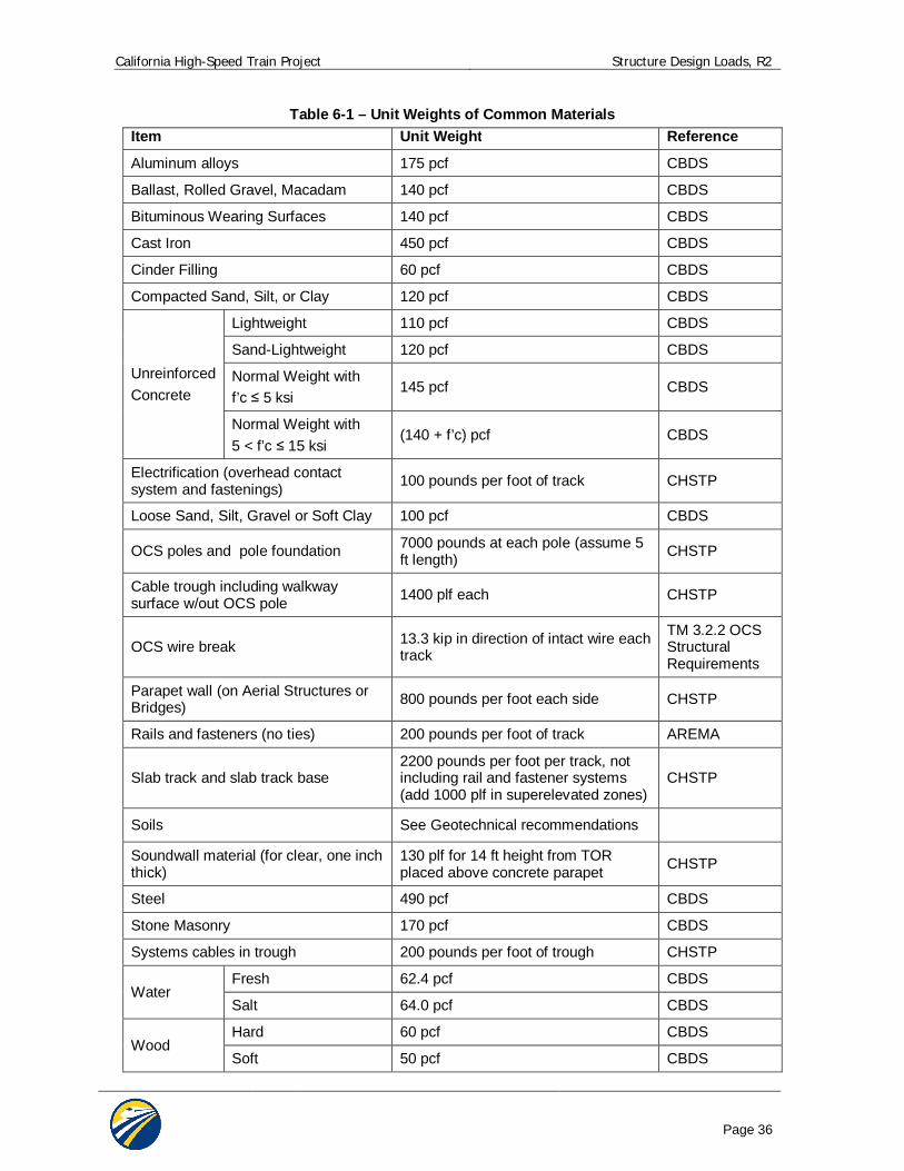
California High-Speed Train Project Structure Design Loads, R2
Page 36
Table 6-1 – Unit Weights of Common Materials Item Unit Weight Reference
Aluminum alloys 175 pcf CBDS
Ballast, Rolled Gravel, Macadam 140 pcf CBDS
Bituminous Wearing Surfaces 140 pcf CBDS
Cast Iron 450 pcf CBDS
Cinder Filling 60 pcf CBDS
Compacted Sand, Silt, or Clay 120 pcf CBDS
Unreinforced Concrete
Lightweight 110 pcf CBDS
Sand-Lightweight 120 pcf CBDS
Normal Weight with f’c 5 ksi
145 pcf CBDS
Normal Weight with 5 < f’c 15 ksi
(140 + f’c) pcf CBDS
Electrification (overhead contact system and fastenings) 100 pounds per foot of track CHSTP
Loose Sand, Silt, Gravel or Soft Clay 100 pcf CBDS
OCS poles and pole foundation 7000 pounds at each pole (assume 5 ft length) CHSTP
Cable trough including walkway surface w/out OCS pole 1400 plf each CHSTP
OCS wire break 13.3 kip in direction of intact wire each track
TM 3.2.2 OCS Structural Requirements
Parapet wall (on Aerial Structures or Bridges) 800 pounds per foot each side CHSTP
Rails and fasteners (no ties) 200 pounds per foot of track AREMA
Slab track and slab track base 2200 pounds per foot per track, not including rail and fastener systems (add 1000 plf in superelevated zones)
CHSTP
Soils See Geotechnical recommendations
Soundwall material (for clear, one inch thick)
130 plf for 14 ft height from TOR placed above concrete parapet CHSTP
Steel 490 pcf CBDS
Stone Masonry 170 pcf CBDS
Systems cables in trough 200 pounds per foot of trough CHSTP
Water Fresh 62.4 pcf CBDS
Salt 64.0 pcf CBDS
Wood Hard 60 pcf CBDS
Soft 50 pcf CBDS
California High-Speed Train Project Structure Design Loads, R2
Page 37
6.4.2 Downdrag Force (DD) Possible development of downdrag on piles or shafts shall be considered. Recommended negative skin friction values shall be as provided for the particular site. If specific design information is not available use CBDS 3.11.8.
6.4.3 Earth Pressures (EV, EH) Substructure elements and underground structures and earth retaining structures shall be proportioned to withstand earth pressure. Recommended soil parameters, earth pressures and loads due to surcharges shall be as provided for the particular site.
Vertical Earth Pressure (EV): Depth of cover shall be measured from the ground surface or roadway crown, or from the street grade, whichever is higher, to the top of the underground structure. Saturated densities of soils shall be used to determine the vertical earth pressure.
Lateral Static Earth Pressure (EH): For structures retaining draining cohesionless (granular) soil, lateral earth pressure shall be determined in accordance with the following paragraphs. For structures retaining other soil types, the lateral earth pressure shall follow the geotechnical recommendations.
Yielding Walls: Yielding walls (i.e., typical cantilever retaining walls) are defined as walls that are unrestrained and free to move at the top for a distance of at least 0.004H. H is defined as the height of the wall from the base of the heel to the finished grade directly above the heel.
For yielding walls, the lateral static earth pressure shall be determined using the active lateral pressures expressed as equivalent fluid pressures.
Rigid Walls: Rigid walls are defined as walls which are restrained at the top so that the amount of deflection required to develop active pressure conditions is not possible. All permanent excavation support walls as well as tunnel portal transitions and U-sections shall be considered as rigid walls.
For rigid walls, the static lateral soil pressure shall be determined using the at-rest lateral pressures expressed as equivalent fluid pressures.
Recommended geotechnical values shall be provided in the Geotechnical Reports. See TM 2.9.2 Geotechnical Reports Preparation Guidelines. If geotechnical design information is not available during preliminary design, use CBDS 3.11.5 Earth Pressure.
6.4.4 Earth Surcharge (ES) Surcharge loads (ES) are vertical or lateral loads resulting from loads applied above or below the adjacent ground surface. Procedures for determining surcharge load shall be per geotechnical recommendations.
Underground structures and walls shall be designed for loading from existing adjacent buildings or structures. Consideration shall be given to the maximum and minimum loads that can be transferred to the design structure, and design loads shall be assumed to be the same as those for which the adjacent structure was designed. In the absence of this information, loads based on provisions in the CBC concurrent with the heaviest occupancy for which the building is suitable, shall be used.
Surcharge loads from adjacent buildings and structures commonly result from combinations of dead load, live load, etc. Due to this, surcharge loads applied for the design structure need not be factored twice, and shall be taken as the greater of the unfactored surcharge loading multiplied by the specified factor, ES, or the factored surcharge loading with ES equal to 1.0.
Structures that may support future developments above CHSTP facilities shall be designed to reflect the future load. Surcharge loads modeling future developments shall not be applied concurrently with traffic or future traffic surcharges in the same locations. If a future development extends to the surface land adjacent to an underground structure, then a surcharge shall be applied for design. The surcharge shall model the loading due to the maximum development currently allowed by zoning.
California High-Speed Train Project Structure Design Loads, R2
Page 38
Construction activities may result in permanent or temporary loads from equipment, trucks, drayage, stockpiling of materials, or excavated earth. A surcharge shall be applied to all underground structures, unless: 1) positive and recognizable means are provided at the ground surface to ensure that the above types of loadings cannot occur; and, 2) the Authority specifically permits in writing, the application of a surcharge of lesser magnitude.
The vertical surcharge shall be considered as a static uniform load as follows:
600 psf, for h < 5 feet
600-40 (h-5) psf, for 5 ft h 20 feet
0 psf, for h > 20 feet
h = vertical distance from the top of structure to ground surface.
Surcharge loads representing construction activities need not be applied concurrently with traffic or future traffic surcharges in the same location.
See Subsection 6.5.1.7 Live Load Surcharge (LLS).
6.4.5 Earth Settlement Effects (SE) Earth settlement effects (SE) are forces or displacements imposed on a structure due to either uniform or differential settlement under sustained loading. Limiting values of settlement as given in the TM 2.9.10 Geotechnical Design Guidelines shall be used.
Tolerable settlement on foundations shall be developed by the structure designer consistent with the function and type of structure, fixity of bearings, anticipated service life, and consequences of unacceptable displacements on structural and operational performance.
At and near water crossings, scour potential should also be considered for earth settlement effects on shallow foundations.
6.4.6 Creep Effects (CR) For the effects due to creep of concrete (CR), the requirements in CBDS Section 5.4.2.3 shall be used.
6.4.7 Shrinkage Effects (SH) For the effects due to shrinkage of concrete (SH), the requirements in CBDS Section 5.4.2.3 shall be used.
6.4.8 Secondary Forces from Prestressing (PS) Secondary forces from prestressing (PS) shall be considered. Such secondary forces arise during prestress of statically indeterminate structures, which produce internal forces and support reactions. Secondary forces are generally obtained by subtracting the primary prestress forces from the total prestressing.
6.4.9 Locked-in Construction Forces (EL) Miscellaneous locked-in construction force effects (EL) resulting from the construction process shall be considered. Such effects include jacking apart adjacent cantilevers during segmental construction and bracing at excavation supports.
6.4.10 Water Loads (WA) The effects of ground water hydrostatic force, including static pressure of water, buoyancy, stream pressure, and wave loads (WA) shall be considered using the requirements in CBDS Section 3.7 and the recommended geotechnical values.
The effects of ground water hydrostatic force, including buoyancy (WA) shall be considered in the design of underground structures and the substructure of aerial structures and buildings, including foundations and piling.
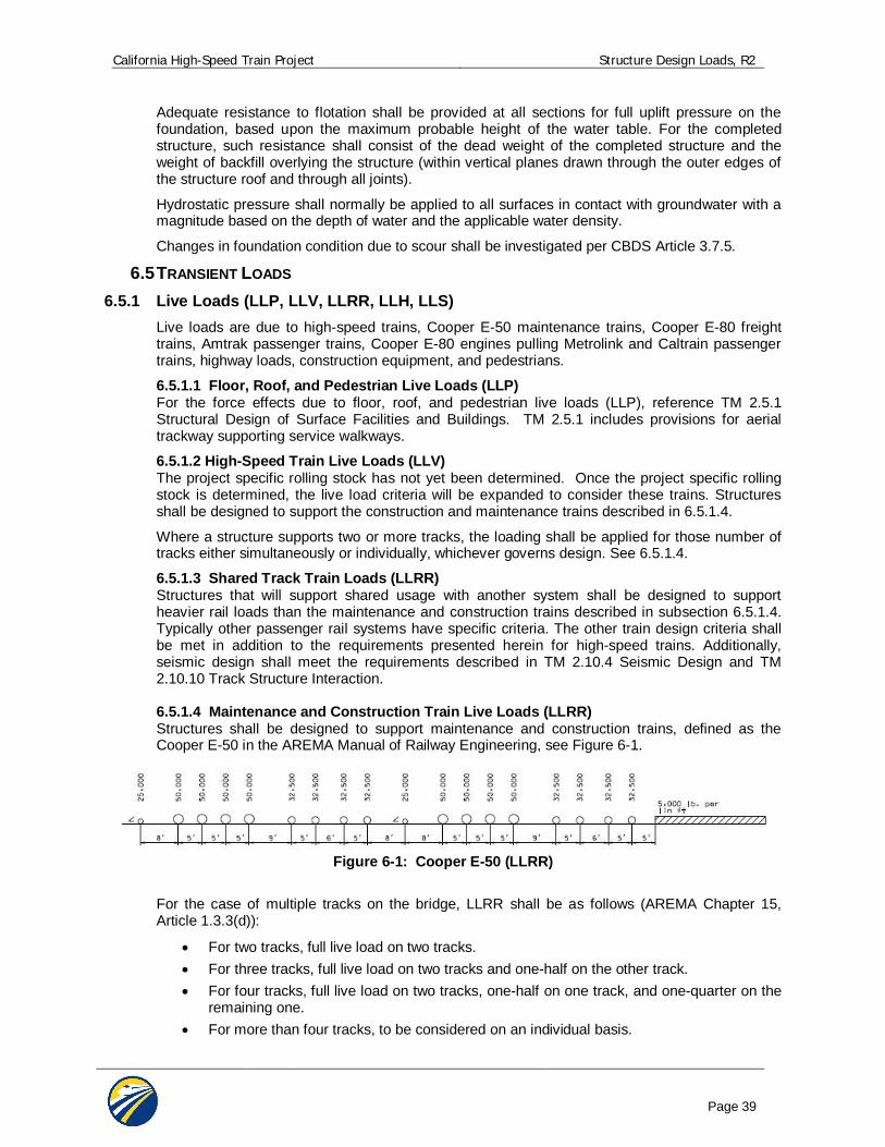
California High-Speed Train Project Structure Design Loads, R2
Page 39
Adequate resistance to flotation shall be provided at all sections for full uplift pressure on the foundation, based upon the maximum probable height of the water table. For the completed structure, such resistance shall consist of the dead weight of the completed structure and the weight of backfill overlying the structure (within vertical planes drawn through the outer edges of the structure roof and through all joints).
Hydrostatic pressure shall normally be applied to all surfaces in contact with groundwater with a magnitude based on the depth of water and the applicable water density.
Changes in foundation condition due to scour shall be investigated per CBDS Article 3.7.5.
6.5 TRANSIENT LOADS 6.5.1 Live Loads (LLP, LLV, LLRR, LLH, LLS)
Live loads are due to high-speed trains, Cooper E-50 maintenance trains, Cooper E-80 freight trains, Amtrak passenger trains, Cooper E-80 engines pulling Metrolink and Caltrain passenger trains, highway loads, construction equipment, and pedestrians.
6.5.1.1 Floor, Roof, and Pedestrian Live Loads (LLP) For the force effects due to floor, roof, and pedestrian live loads (LLP), reference TM 2.5.1 Structural Design of Surface Facilities and Buildings. TM 2.5.1 includes provisions for aerial trackway supporting service walkways.
6.5.1.2 High-Speed Train Live Loads (LLV) The project specific rolling stock has not yet been determined. Once the project specific rolling stock is determined, the live load criteria will be expanded to consider these trains. Structures shall be designed to support the construction and maintenance trains described in 6.5.1.4.
Where a structure supports two or more tracks, the loading shall be applied for those number of tracks either simultaneously or individually, whichever governs design. See 6.5.1.4.
6.5.1.3 Shared Track Train Loads (LLRR) Structures that will support shared usage with another system shall be designed to support heavier rail loads than the maintenance and construction trains described in subsection 6.5.1.4. Typically other passenger rail systems have specific criteria. The other train design criteria shall be met in addition to the requirements presented herein for high-speed trains. Additionally, seismic design shall meet the requirements described in TM 2.10.4 Seismic Design and TM 2.10.10 Track Structure Interaction. 6.5.1.4 Maintenance and Construction Train Live Loads (LLRR) Structures shall be designed to support maintenance and construction trains, defined as the Cooper E-50 in the AREMA Manual of Railway Engineering, see Figure 6-1.
Figure 6-1: Cooper E-50 (LLRR)
For the case of multiple tracks on the bridge, LLRR shall be as follows (AREMA Chapter 15, Article 1.3.3(d)):
For two tracks, full live load on two tracks. For three tracks, full live load on two tracks and one-half on the other track. For four tracks, full live load on two tracks, one-half on one track, and one-quarter on the
remaining one. For more than four tracks, to be considered on an individual basis.
California High-Speed Train Project Structure Design Loads, R2
Page 40
The tracks selected for full live load shall be those tracks that will produce the most critical design condition on the member under consideration. 6.5.1.5 Amtrak Live Loads (LLRR) Segments of the alignment are required to be designed to provide for Amtrak service. These segments shall be designed to support Cooper E-50 trains as described in the AREMA Manual of Railway Engineering. The structure shall also meet all the requirements for structures supporting high-speed trains, including but not limited to track structure compatibility and the seismic requirements. These structures shall also be designed to resist two axles weighing 70 kips each, with a longitudinal spacing of 9.0 feet. This additional loading is required to account for local effects of Amtrak locomotives. 6.5.1.6 Highway Live Loads (LLH) Facilities designed to support highway loads (LLH) shall be designed for a minimum of HL-93 Truck Loading based on CBDS Section 3.6.1. For facilities that support highway permit loads, Caltrans guidelines shall be followed for the routing and sizes of the permit vehicles.
For underground structures beneath city streets or planned roadways including culverts, spread footings and pile caps, the distribution of live load shall be in accordance with the following:
Fill height less than two feet: Live load shall be applied as concentrated wheel loads directly to the top of the slab in addition to the uniform load specified in HL-93 loading.
Fill height greater than two feet: Concentrated wheel loads shall be distributed over the contact area, and increased by the depth of fill and added to the HL-93 uniform load.
When distribution areas overlap, the total load shall be uniformly distributed over an area defined by the outside limits of the individual areas.
The design lane load shall be distributed over that portion of a lane width as described in CBDS.
6.5.1.7 Live Load Surcharge (LLS) An area surcharge (LLS) shall be applied at the ground surface both over and adjacent to underground and retaining structures, as applicable, to account for presence of live load. Live load surcharge may result from presence of LLRR, LLV, LLH, possible future roadways, sidewalk live loads, or construction live loads.
Methods for lateral distribution of live load surcharge due to rail loading shall be in accordance with AREMA, Chapter 8, Article 5.3.1 and 16.4.3. Lateral distribution of highway surcharge shall be in accordance with CBDS, Article 3.6.1.2.6. No impact factors apply to LLS for walls. Buried components shall be subject to impact as follows:
%0)125.00.1(*)( DIburiedI
Where:
I = impact in accordance with Article 6.5.2, herein
D = minimum depth of earth cover above structure (ft)
Recommended coefficients for lateral surcharge loading shall follow the geotechnical recommendations.
6.5.1.8 Live Loads for Fatigue Assessment For structures carrying high-speed trains, the project specific rolling stock (LLV) plus impact (I) shall be used for fatigue assessment of all structures. The methods of CBDS Subsection 3.6.1.4 shall be used to evaluate fatigue loads.
The fatigue assessment shall be performed for all structural elements which are subjected to fluctuations of stress. For structures supporting multiple tracks the loading shall be applied to a minimum of two (2) tracks in the most unfavorable positions. The fatigue damage shall be assessed over the required structural life of 100 years. During maximum service condition of 12 trains per hour, 20 hours service/day, and 32 axles per train there are 2.8 million axle loads per track per year.
California High-Speed Train Project Structure Design Loads, R2
Page 41
6.5.2 Vertical Impact Effect (IM) Moving trains and vehicles impart dynamic load to bridges, which are considered through a dynamic coefficient or impact factor. The static effects of the design train loads, other than centrifugal force, traction, braking, nosing and hunting forces shall be increased by the percentages specified.
Impact applies to the following:
1. Superstructures, including steel or concrete supporting columns, steel towers, legs of rigid frames, and generally those portions of the structure which extend down to the main foundation.
2. The portion above the ground line of concrete or steel piles that support the superstructure directly.
Impact does not apply to the following: 1. Retaining walls, wall-type piers, and piles except those described above. 2. Foundations and footings entirely below ground, and base slabs which are in direct
contact with earth. 3. Floor, roof, and pedestrian live loads (LLP).
For LLRR
Static impact factors (IM) for LLRR shall be taken from AREMA and Eurocode Specifications.
Ballasted track:
Reinforced or prestressed concrete bridges: (AREMA Chapter 8, Article 2.2.3(d)):
%60IM where L < 14 ft
LIM 225 where 14 ft < L 127 ft
%20IM where L > 127 ft
Steel bridges (AREMA Chapter 15, Article 1.3.5(c)):
1600340
2LIM where L < 80 ft
3060016
LIM where L 80 ft
For direct fixation on concrete slab track with spans less than 40 feet, European Standard EN 1991-2 shall be used as modified below. For longer spans, AREMA ballasted track impact factors shall be used as a lower bound.
For direct fixation on concrete slab track:
%10027.02.0305.0
16.2100L
IM where L 40 ft
L = span length for member under consideration (i.e. main girder, bridge deck, etc)
The calculated value shall be applied at top of rail as a percentage of live load.
An additional ±20% imbalance of live load shall be applied to each rail as a vertical force to model the couple caused by rocking of the train. The couple shall be applied on each track in the direction which will produce the most unfavorable effect in the member under consideration.
California High-Speed Train Project Structure Design Loads, R2
Page 42
For LLV
Dynamic analysis is required for structures carrying high-speed trains (LLV) in sites with speeds greater than 200 mph in order to determine impact effects.
For more dynamic analysis requirements, see TM 2.10.10 Track Structure Interaction.
For LLH
Section 6.6.2 shall be used for determining impact factors (IM) associated with highway loading (LLH), CBDS Dynamic Load Allowance (IM).
6.5.3 Centrifugal Force (CF) For structures carrying high-speed trains on a curved alignment, centrifugal force (CF) shall be considered. Multiple presence factors may apply to centrifugal forces.
For LLRR and LLV
The centrifugal force (CF) is a function of the axle weights of the train live load (LLRR or LLV), train speed, and horizontal radius of curvature.
For LLRR, CF acts at 8 feet above top of rail.
For LLV, CF acts at 6 feet above top of rail.
CF = (LLRR or LLV) x [0.0668*V2 *f /R]
V = train speed (mph)
R = horizontal radius of curvature (ft)
f = reduction factor, not to be taken less than 0.35:
f = 1, for LLRR, for V 75 mph
f = 1 - [(V - 75)/621.4] x [506/V + 1.75] x [1 - (9.45/ L)1/2] 0.35, for LLRR, V > 75 mph
f = 1, for LLV, all speeds
L = length in feet of the loaded portion of curved track on the bridge.
If the maximum line speed at the site is in excess of 75 mph, the centrifugal force shall be investigated at 75 mph with a reduction factor of 1.0, and at the maximum line speed with a reduction factor less than 1.0.
The effect of superelevation shall be considered when present. The superelevation effect shifts the centroid of the train laterally producing an unequal transverse distribution between rails. Consideration shall be given to the cases in which the train is moving and in the at rest condition.
For LLH
For structures carrying highway loads on a curved alignment, centrifugal force (CF) shall be per CBDS Section 3.6.3.
6.5.4 Traction and Braking Forces (LF) For LLRR
For traction and braking forces (LF) from passenger trains, freight trains, maintenance and construction trains (LLRR) use AREMA Article 2.2.3:
Traction force = N(25 L) kips, acting 3 feet above top of rail
Braking force = N(45 + 1.2L) kips, acting 8 feet above top of rail
Where:
L = length in feet of portion of bridge under consideration
N = ratio of Cooper train load to Cooper E80 loading for the sizes of trains that will use the structure (i.e., for Cooper E50, N = 0.625)
California High-Speed Train Project Structure Design Loads, R2
Page 43
The LF loads for LLRR are to be distributed equally over the length of the train. Multiple presence factors shall apply.
For LLV
For traction and braking forces (LF) from high-speed trains (LLV) shall be
Traction force = 2.26L (kips) or 25% of train load (if known), with a maximum value of 225kips, acting at top of rail
Braking force = 1.37L (kips) or 25% of train load (if known), with a maximum value of 1350kips, acting at top of rail
where L = length in feet of portion of bridge under consideration.
These loads are to be distributed equally to all axles over the length of the train.
Note that traction and braking forces will be reviewed and possibly revised when project-specific rolling stock is selected.
For dynamic analyses of the Longitudinal distribution of the traction and braking forces (LF) from high-speed trains through the rails and rail fasteners to the track slabs on the decks to the substructures shall follow the recommendations in TM 2.10.10 Track Structure Interaction.
For LLH
For braking forces (LF) from highway loading (LLH), CBDS Section 3.6.4 shall be used.
6.5.5 Nosing and Hunting Effects (NE) For LLRR and LLH
Nosing and hunting effects do not apply to LLRR and LLH.
For LLV
For structures carrying high-speed trains with slab track and direct fixation fasteners, nosing and hunting effects (NE) of the wheels contacting the rails shall be accounted for by an 11 kip force per axle applied to the top of the low rail, perpendicular to the track centerline, acting horizontal at the most unfavorable position.
NE is not applicable for the design of structures with ballasted track.
NE shall be applied simultaneously with centrifugal force (CF).
6.5.6 Wind Loads (WS, WL) For LLRR and LLV
Wind Pressure on Structures (WS) and Wind Pressure on Trains (WL) shall be calculated in accordance with requirements in CBDS Section 3.8 with the following modifications:
(1) The effective wind area shall include the exposed area of all bridge elements, OCS poles, and catenary. For parapets and barriers, shielding of downwind elements from those upwind shall not be considered (i.e. the exposed area shall include the summation of all parapets of significant height contained on the bridge).
(2) Use of “Suburban” and “City” exposure categories to calculate design wind velocity is discouraged and shall be accepted only on a case-by-case basis.
(3) The base lateral load for Wind Pressure on Vehicles (WL) shall be revised to 0.300 klf perpendicular to the train acting 8 feet above the top of rail. CBDS Table 3.8.1.3-1 Wind Components on Live Load for skewed angles of incidence shall be revised proportionally to reflect the modified base lateral load.
(4) For structures which utilize soundwalls or windwalls capable of effectively shielding the train from wind loading, consideration may be given to a reduction of WL. The reduction may be taken as the fractional height of train which is shielded by the wall, assuming the
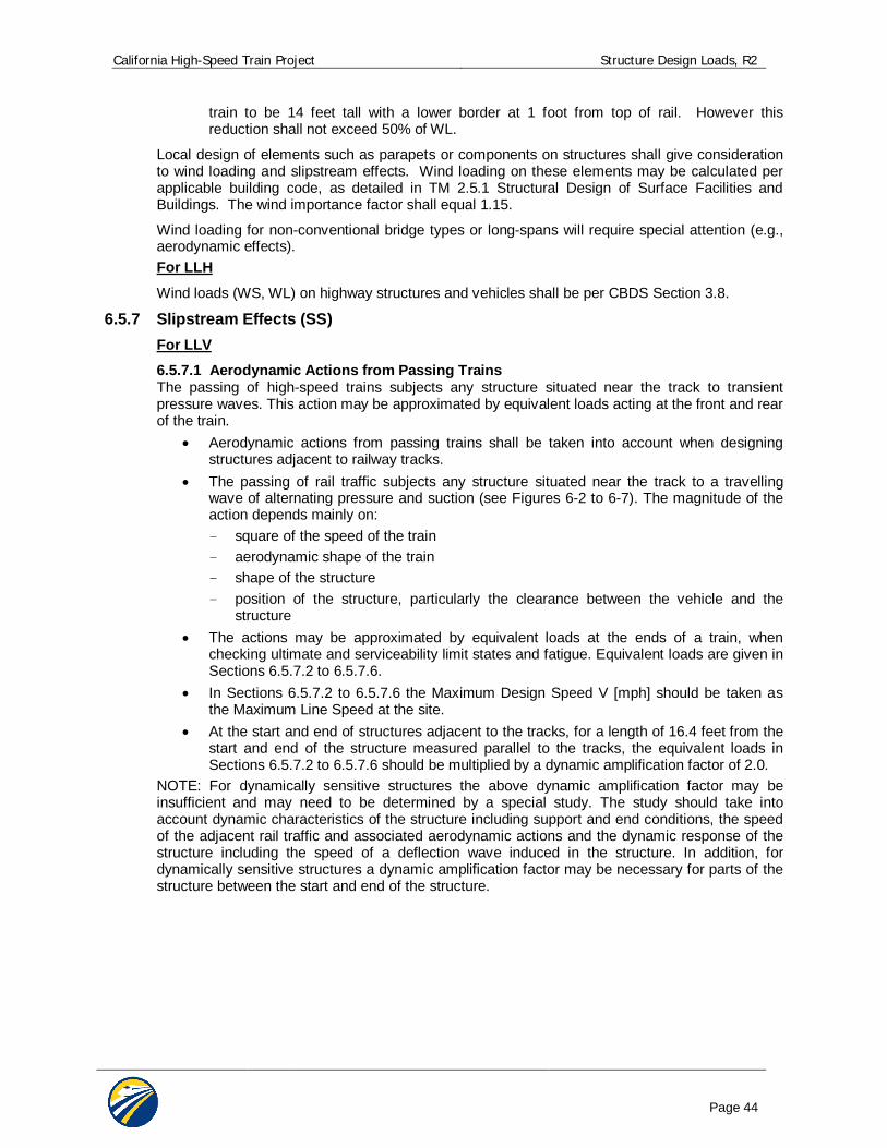
California High-Speed Train Project Structure Design Loads, R2
Page 44
train to be 14 feet tall with a lower border at 1 foot from top of rail. However this reduction shall not exceed 50% of WL.
Local design of elements such as parapets or components on structures shall give consideration to wind loading and slipstream effects. Wind loading on these elements may be calculated per applicable building code, as detailed in TM 2.5.1 Structural Design of Surface Facilities and Buildings. The wind importance factor shall equal 1.15.
Wind loading for non-conventional bridge types or long-spans will require special attention (e.g., aerodynamic effects). For LLH
Wind loads (WS, WL) on highway structures and vehicles shall be per CBDS Section 3.8.
6.5.7 Slipstream Effects (SS) For LLV
6.5.7.1 Aerodynamic Actions from Passing Trains The passing of high-speed trains subjects any structure situated near the track to transient pressure waves. This action may be approximated by equivalent loads acting at the front and rear of the train.
Aerodynamic actions from passing trains shall be taken into account when designing structures adjacent to railway tracks.
The passing of rail traffic subjects any structure situated near the track to a travelling wave of alternating pressure and suction (see Figures 6-2 to 6-7). The magnitude of the action depends mainly on: - square of the speed of the train - aerodynamic shape of the train - shape of the structure - position of the structure, particularly the clearance between the vehicle and the
structure The actions may be approximated by equivalent loads at the ends of a train, when
checking ultimate and serviceability limit states and fatigue. Equivalent loads are given in Sections 6.5.7.2 to 6.5.7.6.
In Sections 6.5.7.2 to 6.5.7.6 the Maximum Design Speed V [mph] should be taken as the Maximum Line Speed at the site.
At the start and end of structures adjacent to the tracks, for a length of 16.4 feet from the start and end of the structure measured parallel to the tracks, the equivalent loads in Sections 6.5.7.2 to 6.5.7.6 should be multiplied by a dynamic amplification factor of 2.0.
NOTE: For dynamically sensitive structures the above dynamic amplification factor may be insufficient and may need to be determined by a special study. The study should take into account dynamic characteristics of the structure including support and end conditions, the speed of the adjacent rail traffic and associated aerodynamic actions and the dynamic response of the structure including the speed of a deflection wave induced in the structure. In addition, for dynamically sensitive structures a dynamic amplification factor may be necessary for parts of the structure between the start and end of the structure.
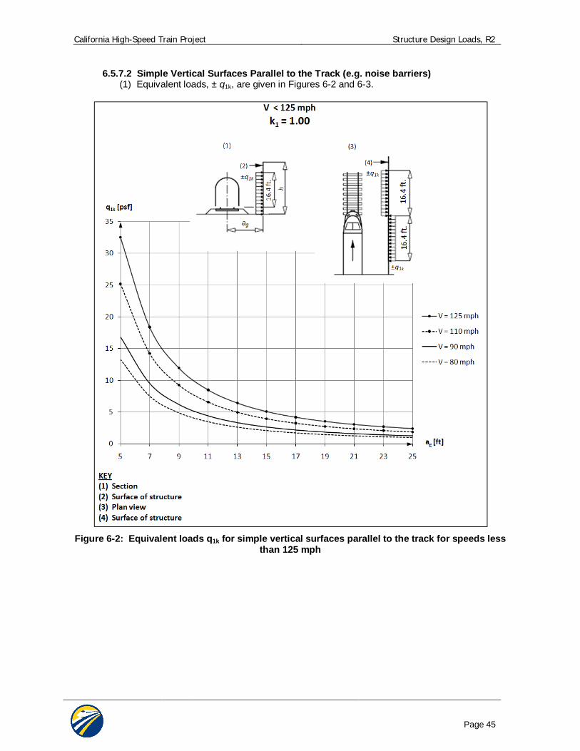
California High-Speed Train Project Structure Design Loads, R2
Page 45
6.5.7.2 Simple Vertical Surfaces Parallel to the Track (e.g. noise barriers) (1) Equivalent loads, ± q1k, are given in Figures 6-2 and 6-3.
Figure 6-2: Equivalent loads q1k for simple vertical surfaces parallel to the track for speeds less
than 125 mph
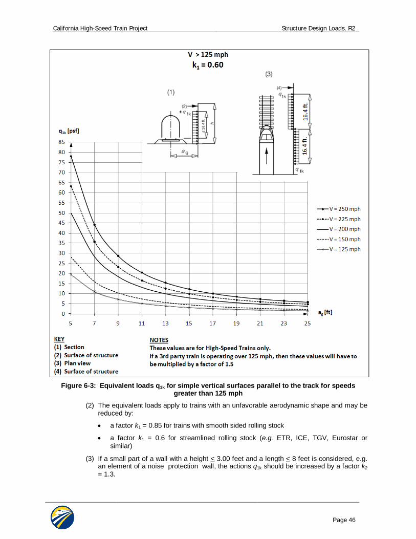
California High-Speed Train Project Structure Design Loads, R2
Page 46
Figure 6-3: Equivalent loads q1k for simple vertical surfaces parallel to the track for speeds
greater than 125 mph
(2) The equivalent loads apply to trains with an unfavorable aerodynamic shape and may be reduced by:
a factor k1 = 0.85 for trains with smooth sided rolling stock
a factor k1 = 0.6 for streamlined rolling stock (e.g. ETR, ICE, TGV, Eurostar or similar)
(3) If a small part of a wall with a height < 3.00 feet and a length < 8 feet is considered, e.g. an element of a noise protection wall, the actions q1k should be increased by a factor k2 = 1.3.
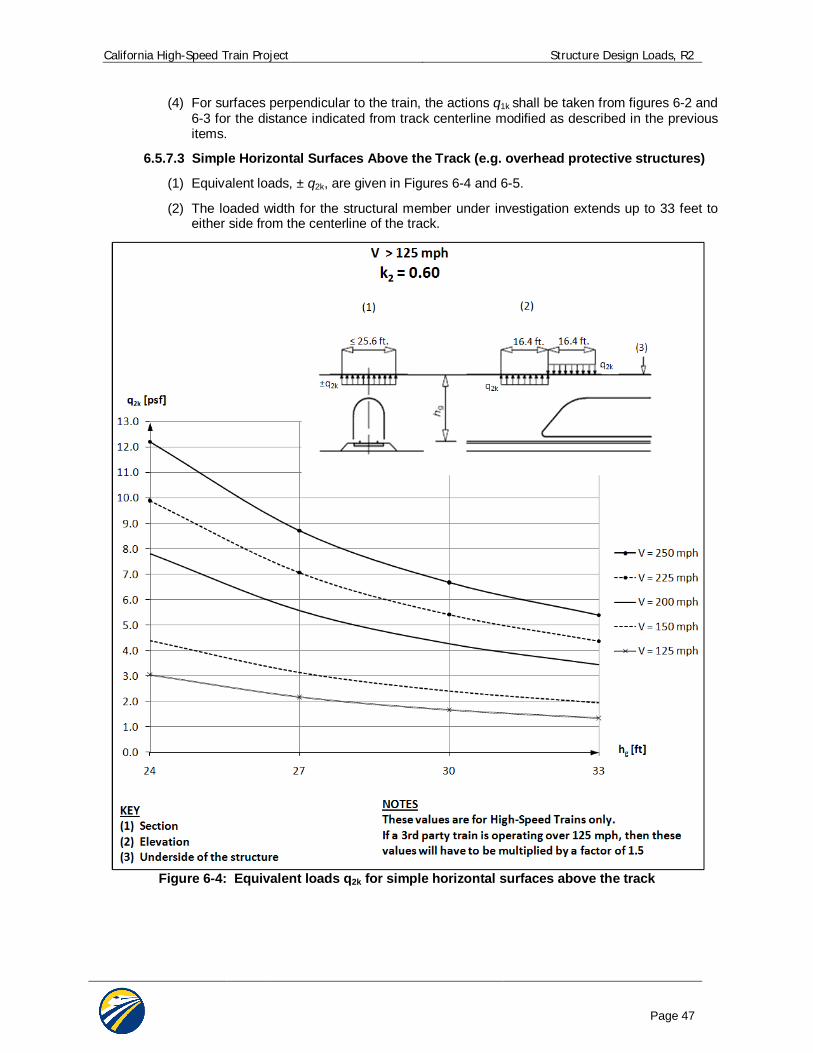
California High-Speed Train Project Structure Design Loads, R2
Page 47
(4) For surfaces perpendicular to the train, the actions q1k shall be taken from figures 6-2 and 6-3 for the distance indicated from track centerline modified as described in the previous items.
6.5.7.3 Simple Horizontal Surfaces Above the Track (e.g. overhead protective structures)
(1) Equivalent loads, ± q2k, are given in Figures 6-4 and 6-5.
(2) The loaded width for the structural member under investigation extends up to 33 feet to either side from the centerline of the track.
Figure 6-4: Equivalent loads q2k for simple horizontal surfaces above the track
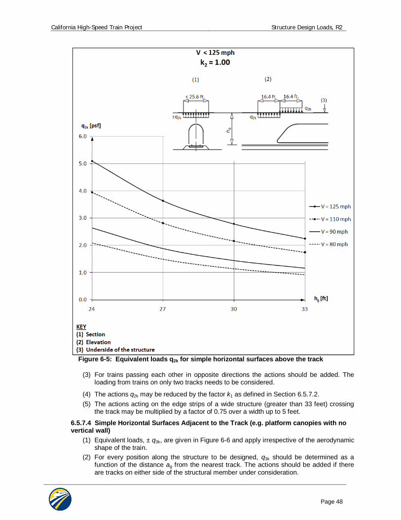
California High-Speed Train Project Structure Design Loads, R2
Page 48
Figure 6-5: Equivalent loads q2k for simple horizontal surfaces above the track
(3) For trains passing each other in opposite directions the actions should be added. The loading from trains on only two tracks needs to be considered.
(4) The actions q2k may be reduced by the factor k1 as defined in Section 6.5.7.2. (5) The actions acting on the edge strips of a wide structure (greater than 33 feet) crossing
the track may be multiplied by a factor of 0.75 over a width up to 5 feet.
6.5.7.4 Simple Horizontal Surfaces Adjacent to the Track (e.g. platform canopies with no vertical wall)
(1) Equivalent loads, ± q3k, are given in Figure 6-6 and apply irrespective of the aerodynamic shape of the train.
(2) For every position along the structure to be designed, q3k should be determined as a function of the distance ag from the nearest track. The actions should be added if there are tracks on either side of the structural member under consideration.
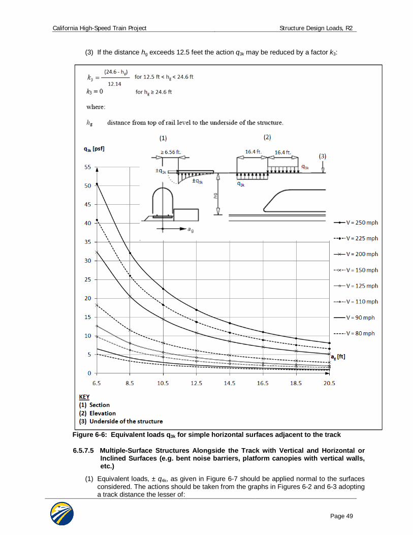
California High-Speed Train Project Structure Design Loads, R2
Page 49
(3) If the distance hg exceeds 12.5 feet the action q3k may be reduced by a factor k3:
Figure 6-6: Equivalent loads q3k for simple horizontal surfaces adjacent to the track
6.5.7.5 Multiple-Surface Structures Alongside the Track with Vertical and Horizontal or Inclined Surfaces (e.g. bent noise barriers, platform canopies with vertical walls, etc.)
(1) Equivalent loads, ± q4k, as given in Figure 6-7 should be applied normal to the surfaces considered. The actions should be taken from the graphs in Figures 6-2 and 6-3 adopting a track distance the lesser of:
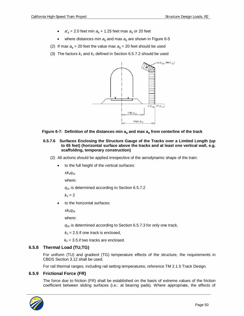
California High-Speed Train Project Structure Design Loads, R2
Page 50
a'g = 2.0 feet min ag + 1.25 feet max ag or 20 feet
where distances min ag and max ag are shown in Figure 6-5
(2) If max ag > 20 feet the value max ag = 20 feet should be used
(3) The factors k1 and k2 defined in Section 6.5.7.2 should be used
Figure 6-7: Definition of the distances min ag and max ag from centerline of the track
6.5.7.6 Surfaces Enclosing the Structure Gauge of the Tracks over a Limited Length (up to 65 feet) (horizontal surface above the tracks and at least one vertical wall, e.g. scaffolding, temporary construction)
(2) All actions should be applied irrespective of the aerodynamic shape of the train:
to the full height of the vertical surfaces:
±k4q1k
where:
q1k is determined according to Section 6.5.7.2
k4 = 2
to the horizontal surfaces:
±k5q2k
where:
q2k is determined according to Section 6.5.7.3 for only one track,
k5 = 2.5 if one track is enclosed,
k5 = 3.5 if two tracks are enclosed.
6.5.8 Thermal Load (TU,TG) For uniform (TU) and gradient (TG) temperature effects of the structure, the requirements in CBDS Section 3.12 shall be used.
For rail thermal ranges, including rail setting temperatures, reference TM 2.1.5 Track Design.
6.5.9 Frictional Force (FR) The force due to friction (FR) shall be established on the basis of extreme values of the friction coefficient between sliding surfaces (i.e.: at bearing pads). Where appropriate, the effects of
California High-Speed Train Project Structure Design Loads, R2
Page 51
moisture, degradation, and contamination of sliding or rotating surfaces upon the friction coefficient shall be considered. For further guidance see CBDS 3.13.
6.5.10 Seismic Loads (MCE, OBE) Detailed, project specific seismic design criteria are presented in TM 2.10.4 Seismic Design Criteria. TM 2.10.4 defines seismic design philosophies, seismic analysis/demand methodologies, and structural capacity evaluation procedures for the multiple levels of design earthquakes.
In general, an individual structure may need to comply with multiple performance levels, depending upon its Importance and Technical Classification.
Highway bridges or structures spanning over high-speed train trackways, or highway structures which have the capacity to influence operability of high-speed trains in event of a failure, shall be designed for the seismic requirements per provisions in TM 2.10.4 Seismic Criteria, in addition to Caltrans Seismic Design Criteria (CSDC).
6.5.11 Hydrodynamic Force (WAD) Hydrodynamic pressure effects acting on submerged portions of structures due to seismic motion shall be computed using the method of Goyal and Chopra [12] or by equivalent means.
For possible additional hydrodynamic force effects, see the Geotechnical Design Report.
6.5.12 Dynamic Earth Pressures (ED) Dynamic earth pressure due to seismic motion on retaining structures shall be computed using the methods described in the Geotechnical Design Report.
6.5.13 Derailment Loads (DR) 6.5.13.1 LLRR and LLV In the event of a derailment, the damage to the structures carrying high-speed trains shall be minimal. Overturning or collapse of the structure shall not be allowed. Three design situations shall be considered:
Case I: Derailment of railway vehicles, with the derailed vehicles remaining in the track area on the bridge deck with vehicles retained by the adjacent rail or a containment wall.
Case II: Derailment of railway vehicles, with the derailed vehicles balanced on the edge of the bridge and loading the edge of the superstructure (excluding nonstructural elements such as walkways).
Case III: Derailment of a steel wheel impacting the bridge deck shall be evaluated using the heaviest axle loads of the Cooper E-50. A 100% impact factor shall be applied. This force is used to design the concrete deck slab.
For Case I, collapse of any part of the structure is not permitted. Local minor damage may be tolerated. The structures shall be designed for the following design loads in the Extreme Loading Combination:
Cooper E-50 loading (both point loads and uniformly distributed loading) parallel to the track in the most unfavorable position inside an area of width 1.5 times the track gauge on either side of the centerline of the track, or as limited by containment walls. If a short wall is used for containment of the train within 1.5 times the track gauge, a coincident horizontal load perpendicular to the track direction shall be used, see Section 6.5.13.2. This horizontal load shall be applied at the top of containment wall.
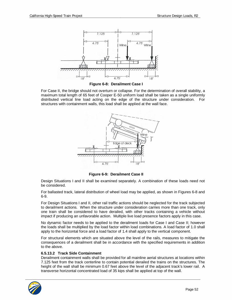
California High-Speed Train Project Structure Design Loads, R2
Page 52
Figure 6-8: Derailment Case I
For Case II, the bridge should not overturn or collapse. For the determination of overall stability, a maximum total length of 65 feet of Cooper E-50 uniform load shall be taken as a single uniformly distributed vertical line load acting on the edge of the structure under consideration. For structures with containment walls, this load shall be applied at the wall face.
Figure 6-9: Derailment Case II
Design Situations I and II shall be examined separately. A combination of these loads need not be considered.
For ballasted track, lateral distribution of wheel load may be applied, as shown in Figures 6-8 and 6-9.
For Design Situations I and II, other rail traffic actions should be neglected for the track subjected to derailment actions. When the structure under consideration carries more than one track, only one train shall be considered to have derailed, with other tracks containing a vehicle without impact if producing an unfavorable action. Multiple live load presence factors apply in this case.
No dynamic factor needs to be applied to the derailment loads for Case I and Case II; however the loads shall be multiplied by the load factor within load combinations. A load factor of 1.0 shall apply to the horizontal force and a load factor of 1.4 shall apply to the vertical component.
For structural elements which are situated above the level of the rails, measures to mitigate the consequences of a derailment shall be in accordance with the specified requirements in addition to the above.
6.5.13.2 Track Side Containment Derailment containment walls shall be provided for all mainline aerial structures at locations within 7.125 feet from the track centerline to contain potential derailed the trains on the structures. The height of the wall shall be minimum 0.67 feet above the level of the adjacent track’s lower rail. A transverse horizontal concentrated load of 35 kips shall be applied at top of the wall.
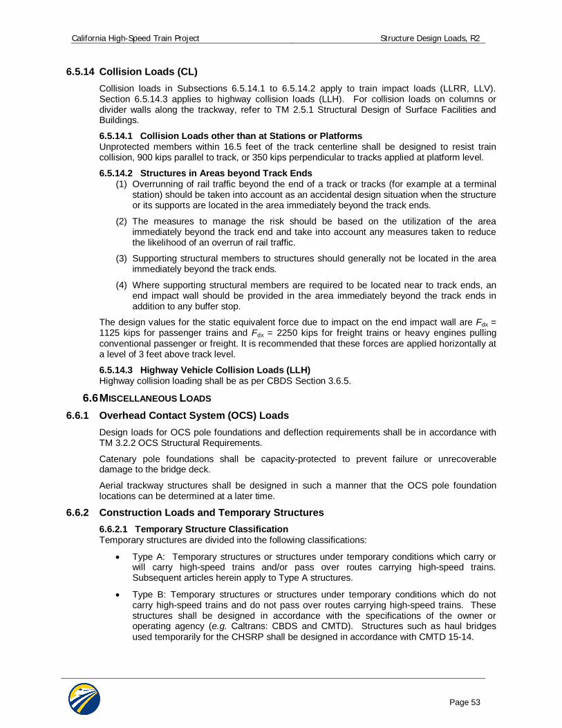
California High-Speed Train Project Structure Design Loads, R2
Page 53
6.5.14 Collision Loads (CL) Collision loads in Subsections 6.5.14.1 to 6.5.14.2 apply to train impact loads (LLRR, LLV). Section 6.5.14.3 applies to highway collision loads (LLH). For collision loads on columns or divider walls along the trackway, refer to TM 2.5.1 Structural Design of Surface Facilities and Buildings. 6.5.14.1 Collision Loads other than at Stations or Platforms Unprotected members within 16.5 feet of the track centerline shall be designed to resist train collision, 900 kips parallel to track, or 350 kips perpendicular to tracks applied at platform level.
6.5.14.2 Structures in Areas beyond Track Ends (1) Overrunning of rail traffic beyond the end of a track or tracks (for example at a terminal
station) should be taken into account as an accidental design situation when the structure or its supports are located in the area immediately beyond the track ends.
(2) The measures to manage the risk should be based on the utilization of the area immediately beyond the track end and take into account any measures taken to reduce the likelihood of an overrun of rail traffic.
(3) Supporting structural members to structures should generally not be located in the area immediately beyond the track ends.
(4) Where supporting structural members are required to be located near to track ends, an end impact wall should be provided in the area immediately beyond the track ends in addition to any buffer stop.
The design values for the static equivalent force due to impact on the end impact wall are Fdx = 1125 kips for passenger trains and Fdx = 2250 kips for freight trains or heavy engines pulling conventional passenger or freight. It is recommended that these forces are applied horizontally at a level of 3 feet above track level.
6.5.14.3 Highway Vehicle Collision Loads (LLH) Highway collision loading shall be as per CBDS Section 3.6.5.
6.6 MISCELLANEOUS LOADS 6.6.1 Overhead Contact System (OCS) Loads
Design loads for OCS pole foundations and deflection requirements shall be in accordance with TM 3.2.2 OCS Structural Requirements.
Catenary pole foundations shall be capacity-protected to prevent failure or unrecoverable damage to the bridge deck.
Aerial trackway structures shall be designed in such a manner that the OCS pole foundation locations can be determined at a later time.
6.6.2 Construction Loads and Temporary Structures 6.6.2.1 Temporary Structure Classification Temporary structures are divided into the following classifications:
Type A: Temporary structures or structures under temporary conditions which carry or will carry high-speed trains and/or pass over routes carrying high-speed trains. Subsequent articles herein apply to Type A structures.
Type B: Temporary structures or structures under temporary conditions which do not carry high-speed trains and do not pass over routes carrying high-speed trains. These structures shall be designed in accordance with the specifications of the owner or operating agency (e.g. Caltrans: CBDS and CMTD). Structures such as haul bridges used temporarily for the CHSRP shall be designed in accordance with CMTD 15-14.
California High-Speed Train Project Structure Design Loads, R2
Page 54
6.6.2.2 Construction Load Combinations Temporary structures or structures under temporary conditions shall be designed to adequately resist conditions at all stages of construction, including all applicable construction loads. Construction load combinations shall include the following:
Applicable strength load combinations: Dead load factors shall not be taken less than 1.25, with construction dead loads taken as permanent loads. Construction transient live load factors shall not be taken less than 1.5. Wind load factors may be reduced by 20%.
Service 1, as applicable.
Seismic load combinations: For 30% design purposes, Load Combination Extreme 3, with revised ground motions having 10% probability of exceedance in 10 years. Performance criteria shall comply with the No Collapse Performance Level (NCL) for an important, standard structure. See TM 2.10.4 Seismic Design Criteria. If significant construction loads are anticipated or specialized equipment present, this mass shall be accounted for in the seismic design.
In the absence of better criteria, a construction live load of 20 psf shall be assumed on the bridge deck.
6.6.2.3 Segmental Construction and Specialized Equipment Construction load combinations per CBDS Article 5.14.2 “Segmental Construction” shall be considered. The temporary seismic load event as described above shall be added to the construction load combination at strength limit states; however a 1.25 load factor may be used for dead and live loads. The temporary seismic event need not be combined with the dynamic construction load impact due to segment drop or equipment impact. For balanced cantilever construction methods an additional 2% of dead load shall be applied to reflect eccentric conditions at the time of a potential seismic event. Single complete span precast girders may be transported to the erection site on top of previously erected girders using specialty heavy load transporters. If this construction method is used then girders shall be designed to support the wheel loads from the transporter. Load factors shall be as described in the previous paragraph.
6.6.3 Rail-Structure Interaction Forces Effects of continuous welded rail (CWR) interaction with the structure through its attachment shall be considered. Design guidance for this interaction is provided in TM 2.10.10 Track Structure Interaction.
Interaction effects of the CWR and structure result after connection of the rail to the structure. These occur in large part due to the following: temperature variations in the rail and structure, braking/traction, creep and shrinkage, and seismic events. Load combinations presented in this document assume this interaction implicit to each load within the combination, with associated load factors.
Structure thermal ranges shall be calculated per provisions in this document. For specific rail information, including thermal ranges, setting temperature, and rail section, refers to TM 2.1.5 Track Design.
TM 2.10.10 Track Structure Interaction also addresses rail-structure interaction under seismic events, including performance objectives and design methodology.
6.6.4 Blast Loading Blast loadings and measures to mitigate are not specified at this time.
California High-Speed Train Project Structure Design Loads, R2
Page 55
6.7 LOAD FACTORS AND LOAD MODIFIERS For structures carrying high-speed trains, the design shall be in accordance with CBDS Section 1.3.2:
i i Qi Rn = Rr Where:
i = load factor applied to force effects (see Tables 6-2, 6-3, and 6-4)
= resistance factor applied to minimal resistance (see Table 6-5)
i = load modifier relating to ductility, redundancy and importance (CBDS, section 1.3.2)
Qi = force effect
Rn = nominal resistance
Rr = factored resistance, Rn
For loads in which a maximum value of “ i” produces an unfavorable action, the value of “ i” shall be equal to 1.05 to account for the 100 year design life of the facility. The load modifier is based upon AASHTO LRFD Article 1.3.2, and is applicable to Strength Limit Load Combinations only.
Variation of load factors for permanent loads, p, are presented in Table 6-3 and 6-4.
Selected resistance factors “ ” are presented in Table 6-5.
6.7.1 Design Load Combinations The load combinations to be used for structures carrying high-speed trains are presented in Table 6-2. The descriptions of the load combinations are as follows:
”Strength 1” is the basic load combination for normal use for design of aerial, earth retaining and cut and cover structures.
”Strength 2” is the load combination for the structure exposed to wind. “Strength 3” is the load combination for very high dead load to live load force effect ratios. “Strength 4” is the load combination for normal use when exposed to wind. “Strength 5” is the load combination for normal use when designing columns for Operating
Basis seismic events, (OBE). Extreme 1” is the load combination for derailment. “Extreme 2” is the load combination for collision. “Extreme 3” is the load combination for Extreme seismic events: Maximum Considered
Earthquake (MCE), ”Service 1” is the basic service load combination for normal use with wind. ”Service 2” is the service load combination intended to control yielding of steel structures and
slip of slip-critical connections due to train load. ”Service 3” is the service load combination relating only to tension in prestressed concrete
columns with the objective of crack control. “Buoyancy at Dewatering Shutoff” is a service load for evaluation of uplift with a minimum
weight structure. “Fatigue” is the fatigue and fracture load combination relating to repetitive train loading.
Note that for each load combination shown below, all physically achievable subsets (i.e., omitting load factors by setting i = 0) which may govern design shall be considered.
Note that other load cases for train and track structure interaction are contained within TM 2.10.10 Track Structure Interaction.
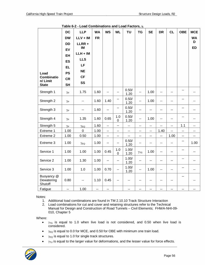
California High-Speed Train Project Structure Design Loads, R2
Page 56
Table 6-2 - Load Combinations and Load Factors, i
Load Combination/ Limit State
DC
DW
DD
EV
EH
ES
EL
PS CR
SH
LLP
LLV + IM
LLRR + IM
LLH + IM
LLS
LF
NE CF
SS
WA
FR
WS WL
TU TG SE DR CL OBE MCE
WAD
ED
Strength 1 P 1.75 1.60 -- -- 0.50/1.20 -- 1.00 -- -- -- --
Strength 2 P -- 1.60 1.40 -- 0.50/1.20 -- 1.00 -- -- -- --
Strength 3 P -- 1.60 -- -- 0.50/1.20 -- -- -- -- -- --
Strength 4 P 1.35 1.60 0.65 1.00
0.50/1.20 -- 1.00 -- -- -- --
Strength 5 P EQ 1.60 -- -- -- -- -- -- -- 1.1 -- Extreme 1 1.00 0 1.00 -- -- -- -- -- 1.40 -- -- -- Extreme 2 1.00 0.50 1.00 -- -- -- -- -- -- 1.00 -- --
Extreme 3 1.00 EQ 1.00 -- -- 0.50/1.20 -- -- -- -- -- 1.00
Service 1 1.00 1.00 1.00 0.45 1.00
1.00/1.20 TG 1.00 -- -- -- --
Service 2 1.00 1.30 1.00 -- -- 1.00/1.20 -- -- -- -- -- --
Service 3 1.00 1.0 1.00 0.70 -- 1.00/1.20 -- 1.00 -- -- -- --
Buoyancy @ Dewatering Shutoff
0.80 -- 1.10 0.45 -- -- -- -- -- -- --
--
Fatigue -- 1.00 -- -- -- -- -- -- -- -- -- Notes:
1. Additional load combinations are found in TM 2.10.10 Track Structure Interaction 2. Load combinations for cut and cover and retaining structures refer to the Technical
Manual for Design and Construction of Road Tunnels – Civil Elements; FHWA-NHI-09-010, Chapter 5
Where: TG is equal to 1.0 when live load is not considered, and 0.50 when live load is
considered. EQ is equal to 0.0 for MCE, and 0.50 for OBE with minimum one train load. EQ is equal to 1.0 for single track structures. TU is equal to the larger value for deformations, and the lesser value for force effects.
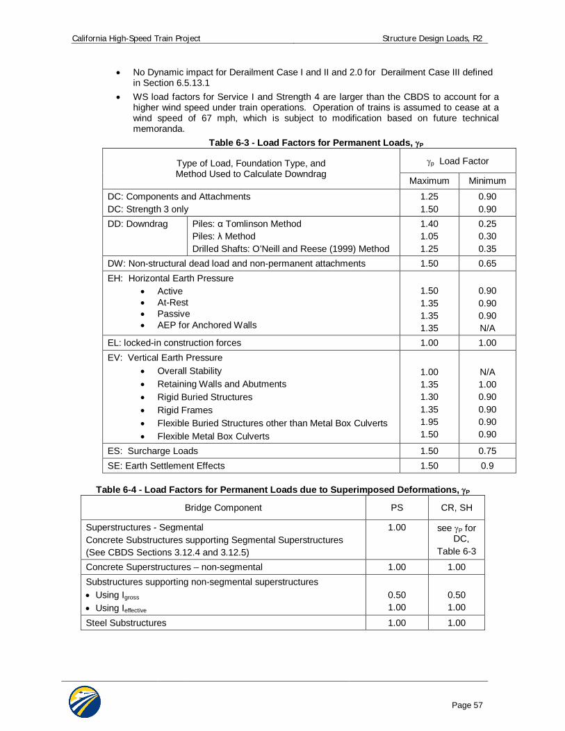
California High-Speed Train Project Structure Design Loads, R2
Page 57
No Dynamic impact for Derailment Case I and II and 2.0 for Derailment Case III defined in Section 6.5.13.1
WS load factors for Service I and Strength 4 are larger than the CBDS to account for a higher wind speed under train operations. Operation of trains is assumed to cease at a wind speed of 67 mph, which is subject to modification based on future technical memoranda.
Table 6-3 - Load Factors for Permanent Loads, P
Type of Load, Foundation Type, and Method Used to Calculate Downdrag
p Load Factor
Maximum Minimum
DC: Components and Attachments DC: Strength 3 only
1.25 1.50
0.90 0.90
DD: Downdrag Piles: Tomlinson Method Piles: Method Drilled Shafts: O’Neill and Reese (1999) Method
1.40 1.05 1.25
0.25 0.30 0.35
DW: Non-structural dead load and non-permanent attachments 1.50 0.65 EH: Horizontal Earth Pressure
Active At-Rest Passive AEP for Anchored Walls
1.50 1.35 1.35 1.35
0.90 0.90 0.90 N/A
EL: locked-in construction forces 1.00 1.00 EV: Vertical Earth Pressure
Overall Stability Retaining Walls and Abutments Rigid Buried Structures Rigid Frames Flexible Buried Structures other than Metal Box Culverts Flexible Metal Box Culverts
1.00 1.35 1.30 1.35 1.95 1.50
N/A 1.00 0.90 0.90 0.90 0.90
ES: Surcharge Loads 1.50 0.75 SE: Earth Settlement Effects 1.50 0.9
Table 6-4 - Load Factors for Permanent Loads due to Superimposed Deformations, P
Bridge Component PS CR, SH
Superstructures - Segmental Concrete Substructures supporting Segmental Superstructures (See CBDS Sections 3.12.4 and 3.12.5)
1.00 see P for DC,
Table 6-3
Concrete Superstructures – non-segmental 1.00 1.00 Substructures supporting non-segmental superstructures Using Igross Using Ieffective
0.50 1.00
0.50 1.00
Steel Substructures 1.00 1.00
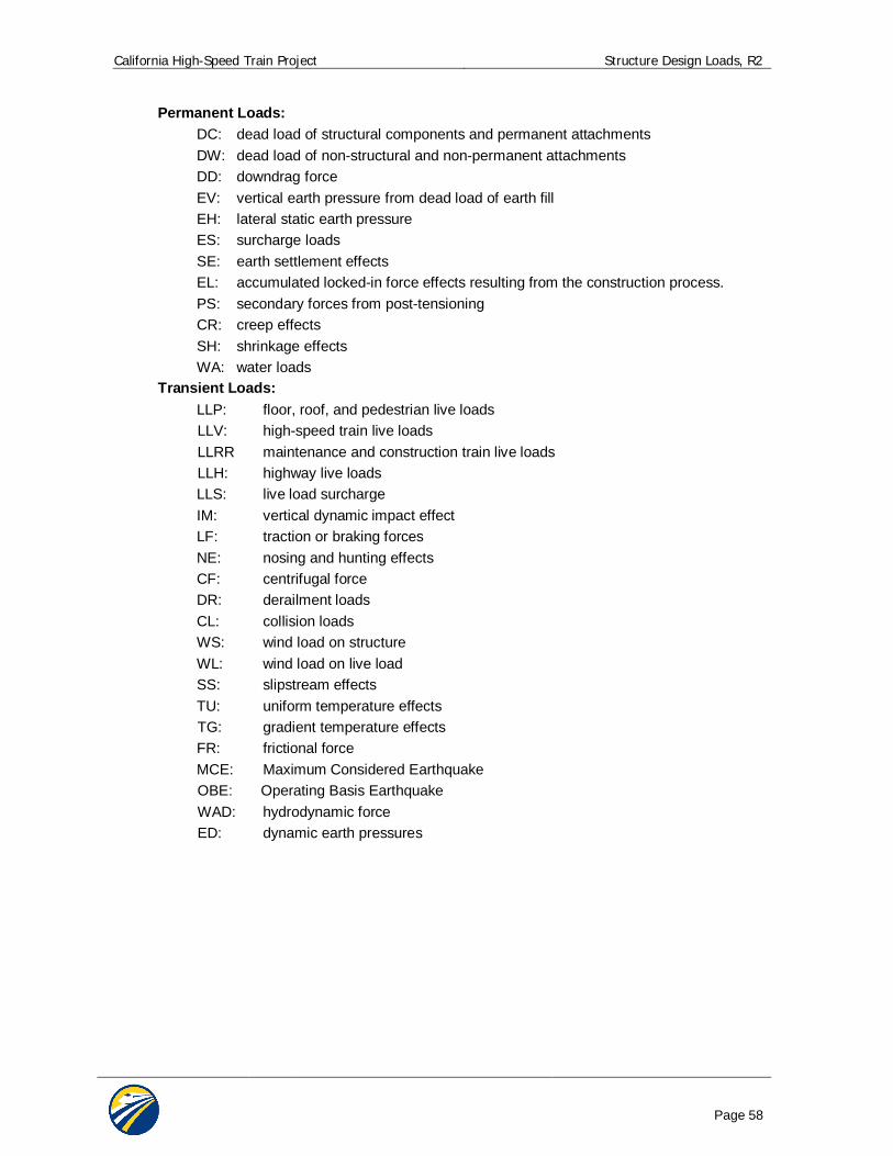
California High-Speed Train Project Structure Design Loads, R2
Page 58
Permanent Loads: DC: dead load of structural components and permanent attachments DW: dead load of non-structural and non-permanent attachments DD: downdrag force EV: vertical earth pressure from dead load of earth fill EH: lateral static earth pressure ES: surcharge loads SE: earth settlement effects EL: accumulated locked-in force effects resulting from the construction process. PS: secondary forces from post-tensioning CR: creep effects SH: shrinkage effects WA: water loads
Transient Loads: LLP: floor, roof, and pedestrian live loads LLV: high-speed train live loads LLRR maintenance and construction train live loads LLH: highway live loads LLS: live load surcharge IM: vertical dynamic impact effect LF: traction or braking forces NE: nosing and hunting effects CF: centrifugal force DR: derailment loads CL: collision loads WS: wind load on structure WL: wind load on live load SS: slipstream effects TU: uniform temperature effects TG: gradient temperature effects FR: frictional force MCE: Maximum Considered Earthquake OBE: Operating Basis Earthquake WAD: hydrodynamic force ED: dynamic earth pressures
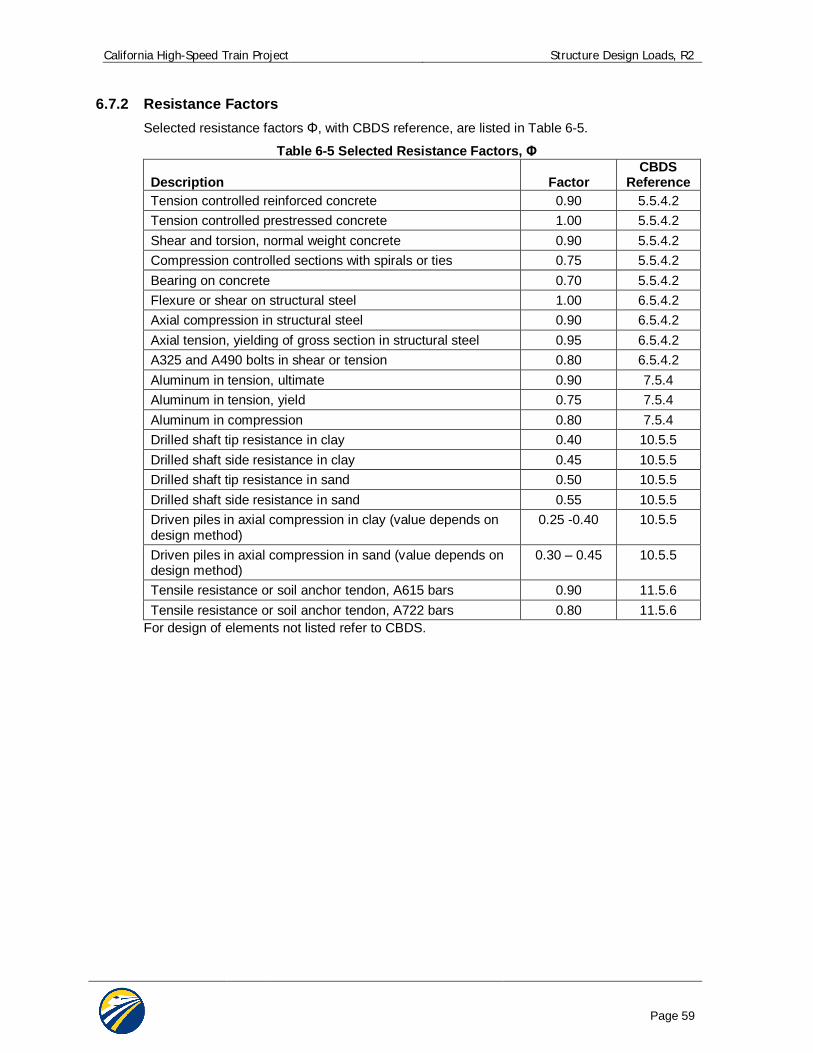
California High-Speed Train Project Structure Design Loads, R2
Page 59
6.7.2 Resistance Factors Selected resistance factors , with CBDS reference, are listed in Table 6-5.
Table 6-5 Selected Resistance Factors, Description
Factor
CBDS Reference
Tension controlled reinforced concrete 0.90 5.5.4.2 Tension controlled prestressed concrete 1.00 5.5.4.2 Shear and torsion, normal weight concrete 0.90 5.5.4.2 Compression controlled sections with spirals or ties 0.75 5.5.4.2 Bearing on concrete 0.70 5.5.4.2 Flexure or shear on structural steel 1.00 6.5.4.2 Axial compression in structural steel 0.90 6.5.4.2 Axial tension, yielding of gross section in structural steel 0.95 6.5.4.2 A325 and A490 bolts in shear or tension 0.80 6.5.4.2 Aluminum in tension, ultimate 0.90 7.5.4 Aluminum in tension, yield 0.75 7.5.4 Aluminum in compression 0.80 7.5.4 Drilled shaft tip resistance in clay 0.40 10.5.5 Drilled shaft side resistance in clay 0.45 10.5.5 Drilled shaft tip resistance in sand 0.50 10.5.5 Drilled shaft side resistance in sand 0.55 10.5.5 Driven piles in axial compression in clay (value depends on design method)
0.25 -0.40 10.5.5
Driven piles in axial compression in sand (value depends on design method)
0.30 – 0.45 10.5.5
Tensile resistance or soil anchor tendon, A615 bars 0.90 11.5.6 Tensile resistance or soil anchor tendon, A722 bars 0.80 11.5.6
For design of elements not listed refer to CBDS.