calibrating spectrum analyzer
TRANSCRIPT

8/3/2019 Calibrating Spectrum Analyzer
http://slidepdf.com/reader/full/calibrating-spectrum-analyzer 1/33
Guide to Calibrating Spectrum Analyzers 1
RF / MICROWAVEFUNDAMENTALS
GUIDE TO CALIBRATINGSPECTRUM ANALYZER
RF MICROWAVE FUNDEMENTALS - Guide to Calibrating Spectrum Analyzers 2
ARCHITECTURE OF SPECTRUMA ANALYZER

8/3/2019 Calibrating Spectrum Analyzer
http://slidepdf.com/reader/full/calibrating-spectrum-analyzer 2/33
RF MICROWAVE FUNDEMENTALS - Guide to Calibrating Spectrum Analyzers 3
KEY ELEMENTS OF SPECTRUMANALYZER
• RF Input Attenuator
– Reduces the input signal to prevent mixer saturations• Mixer
– Down-converting the input signal to a fixed IF signal
• IF Gain – Variable Gain Amplifier at IF frequency to ensure the reference level at the top of
the display to corresponds to the required input signal level
• IF Filter – Tunable IF bandwidth or resolution bandwidth
– Determines how well input signals with small frequency differences can bedistinguished from each other
– Determines the Noise floor
RF MICROWAVE FUNDEMENTALS - Guide to Calibrating Spectrum Analyzers 4
KEY ELEMENTS OF SPECTRUMANALYZER (CON’T)
• Detector/Log Amplifier – Converting RF signal into corresponding Analog Voltages to be displayed on the
screen
• Video Filter
– Uses LPF to average and smooth the displayed traces• Display
– Shows the Spectrum of the measured input signal
• Sweep Generator – Controls the frequency of the Local Oscillator to ensure fixed IF frequency during
the sweep
• Local Oscillator – For down-converting input signal into a fixed IF signal via the Mixer

8/3/2019 Calibrating Spectrum Analyzer
http://slidepdf.com/reader/full/calibrating-spectrum-analyzer 3/33
RF MICROWAVE FUNDEMENTALS - Guide to Calibrating Spectrum Analyzers 5
LIST OF CALIBRATIONTESTS
• Display Linearity
• Noise Floor • Input Attenuator
• Frequency Response and Absolute Amplitude Accuracy
• Filter Bandwidth and Shape
• Noise Sidebands
• Residual FM
• Calibration Amplitude Accuracy
• Marker Count Accuracy
RF MICROWAVE FUNDEMENTALS - Guide to Calibrating Spectrum Analyzers 6
LIST OF CALIBRATION TESTS(CON’T)
• Filter Bandwidth Accuracy
• IF Gain Uncertainty
• Filter Bandwidth Switching
• Reference Level Accuracy
• Frequency Span Accuracy• Frequency Readout Accuracy
• Sweep Time
• Harmonic Distortion
• Third-Order Intermodulation Intercept
• Gain Compression

8/3/2019 Calibrating Spectrum Analyzer
http://slidepdf.com/reader/full/calibrating-spectrum-analyzer 4/33
RF MICROWAVE FUNDEMENTALS - Guide to Calibrating Spectrum Analyzers 7
DISPLAY LINEARITY
• Calibrates the detector/log amplifier, video filter and display components
of the Spectrum Analyzer
RF MICROWAVE FUNDEMENTALS - Guide to Calibrating Spectrum Analyzers 8
DISPLAY LINEARITY (CON’T)

8/3/2019 Calibrating Spectrum Analyzer
http://slidepdf.com/reader/full/calibrating-spectrum-analyzer 5/33
RF MICROWAVE FUNDEMENTALS - Guide to Calibrating Spectrum Analyzers 9
DISPLAY LINEARITY (CON’T)
•Test Setup
RF MICROWAVE FUNDEMENTALS - Guide to Calibrating Spectrum Analyzers 10
DISPLAY LINEARITY (CON’T)
• Verifies Amplitude linearity over a wide dynamic range
• Requires fixed input attenuator and reference levelsettings
• Requires signal source with high-precision attenuationlinearity as a reference standard
• Factors affecting display linearity calibration – Accuracy of reference step attenuators
– Mismatches
– Display resolution of Spectrum Analyzer
– Signal-to-noise ratio of the measurement

8/3/2019 Calibrating Spectrum Analyzer
http://slidepdf.com/reader/full/calibrating-spectrum-analyzer 6/33
RF MICROWAVE FUNDEMENTALS - Guide to Calibrating Spectrum Analyzers 11
NOISE FLOOR TEST
• Has significant bearing on the Spectrum Analyzer’s ability to
measure low-level signals
RF MICROWAVE FUNDEMENTALS - Guide to Calibrating Spectrum Analyzers 12
NOISE FLOOR TEST (CON’T)
8/3/2019 Calibrating Spectrum Analyzer
http://slidepdf.com/reader/full/calibrating-spectrum-analyzer 7/33
RF MICROWAVE FUNDEMENTALS - Guide to Calibrating Spectrum Analyzers 13
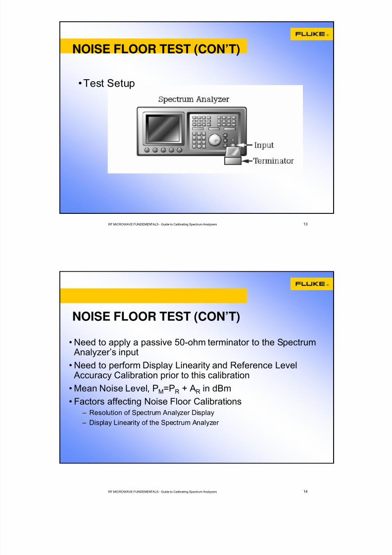
NOISE FLOOR TEST (CON’T)
•Test Setup
RF MICROWAVE FUNDEMENTALS - Guide to Calibrating Spectrum Analyzers 14
NOISE FLOOR TEST (CON’T)
• Need to apply a passive 50-ohm terminator to the SpectrumAnalyzer’s input
• Need to perform Display Linearity and Reference LevelAccuracy Calibration prior to this calibration
• Mean Noise Level, PM=PR + AR in dBm• Factors affecting Noise Floor Calibrations
– Resolution of Spectrum Analyzer Display
– Display Linearity of the Spectrum Analyzer

8/3/2019 Calibrating Spectrum Analyzer
http://slidepdf.com/reader/full/calibrating-spectrum-analyzer 8/33
RF MICROWAVE FUNDEMENTALS - Guide to Calibrating Spectrum Analyzers 15
INPUT ATTENUATOR TEST
•Calibrates the attenuator circuits of the spectrum
analyzer
RF MICROWAVE FUNDEMENTALS - Guide to Calibrating Spectrum Analyzers 16
INPUT ATTENUATOR TEST (CON’T)

8/3/2019 Calibrating Spectrum Analyzer
http://slidepdf.com/reader/full/calibrating-spectrum-analyzer 9/33
RF MICROWAVE FUNDEMENTALS - Guide to Calibrating Spectrum Analyzers 17
INPUT ATTENUATOR TEST (CON’T)
•Test Setup
RF MICROWAVE FUNDEMENTALS - Guide to Calibrating Spectrum Analyzers 18
INPUT ATTENUATOR TEST (CON’T)
•Stepped Attenuator is important as it prevent Mixer from Saturations and damage
•Monitor ∆MKR while increasing external stepattenuator and decreasing the Analyzer’s inputattenuation accordingly
•Attenuator Accuracy,ACC = (ATTNOM – ATTEXT ACTUAL) - ∆MKR

8/3/2019 Calibrating Spectrum Analyzer
http://slidepdf.com/reader/full/calibrating-spectrum-analyzer 10/33
RF MICROWAVE FUNDEMENTALS - Guide to Calibrating Spectrum Analyzers 19
INPUT ATTENUATOR TEST (CON’T)
•Factors affecting Input Attenuator Calibrations – Accuracy of the external reference step attenuators
– Mismatch between the 1dB step attenuator and the SpectrumAnalyzer input
– Display resolution of the Spectrum Analyzer
– Display linearity of the Spectrum Analyzer
– Signal-to-noise ratio of the measurement
RF MICROWAVE FUNDEMENTALS - Guide to Calibrating Spectrum Analyzers 20
ABSOLUTE AMPLITUDE ACCURACYAND FREQUENCY RESPONSE TEST
•Calibrates the attenuator and mixer components of the Spectrum Analyzer

8/3/2019 Calibrating Spectrum Analyzer
http://slidepdf.com/reader/full/calibrating-spectrum-analyzer 11/33
RF MICROWAVE FUNDEMENTALS - Guide to Calibrating Spectrum Analyzers 21
ABSOLUTE AMPLITUDE ACCURACY ANDFREQUENCY RESPONSE TEST (CON’T)
RF MICROWAVE FUNDEMENTALS - Guide to Calibrating Spectrum Analyzers 22
ABSOLUTE AMPLITUDE ACCURACY ANDFREQUENCY RESPONSE TEST (CON’T)
•Test Setup

8/3/2019 Calibrating Spectrum Analyzer
http://slidepdf.com/reader/full/calibrating-spectrum-analyzer 12/33
RF MICROWAVE FUNDEMENTALS - Guide to Calibrating Spectrum Analyzers 23
ABSOLUTE AMPLITUDE ACCURACYAND FREQUENCY RESPONSE TEST(CON’T)
• Measures Amplitude error of the Analyzer as a function of frequency
• Verifies Analyzer’s amplitude response at a fixed levelover its entire frequency
• Requires Power Meter and power sensors
• Compares the Spectrum Analyzer Absolute Power reading and the Power Meter reading at given frequency
• Performed over 25 to 40 frequency points
RF MICROWAVE FUNDEMENTALS - Guide to Calibrating Spectrum Analyzers 24
ABSOLUTE AMPLITUDE ACCURACYAND FREQUENCY RESPONSE TEST(CON’T)
• Factors affecting Calibration Accuracy – Frequency response of reference power sensor
– Mismatch between the power splitter and the power sensor and betweenthe power splitter and the Spectrum Analyzer
– Resolution of the Spectrum Analyzer display
– Display linearity of the Spectrum Analyzer
– Harmonic content of the signal generator output

8/3/2019 Calibrating Spectrum Analyzer
http://slidepdf.com/reader/full/calibrating-spectrum-analyzer 13/33
RF MICROWAVE FUNDEMENTALS - Guide to Calibrating Spectrum Analyzers 25
RESOLUTION BANDWIDTH ANDSELECTIVITY TEST
• Calibrates the bandwidth and bandwidth selectivity of theSpectrum Analyzer’s individual resolution filter
RF MICROWAVE FUNDEMENTALS - Guide to Calibrating Spectrum Analyzers 26
RESOLUTION BANDWIDTH ANDSELECTIVITY TEST (CON’T)

8/3/2019 Calibrating Spectrum Analyzer
http://slidepdf.com/reader/full/calibrating-spectrum-analyzer 14/33
RF MICROWAVE FUNDEMENTALS - Guide to Calibrating Spectrum Analyzers 27
RESOLUTION BANDWIDTH ANDSELECTIVITY TEST (CON’T)
•Test Setup
RF MICROWAVE FUNDEMENTALS - Guide to Calibrating Spectrum Analyzers 28
RESOLUTION BANDWIDTH ANDSELECTIVITY TEST (CON’T)
• Bandwidth selectivity (Shape Factor) measures the ability of the Analyzer to resolve closely-spaced signals of unequalamplitude
• Bandwidth Selectivity = ∆f 60dB/ ∆f 3dB
• Factors affecting Bandwidth Selectivity Test – Frequency Span/delta-marker
– Uncertainty of the span per division
– Display linearity of the Spectrum Analyzer

8/3/2019 Calibrating Spectrum Analyzer
http://slidepdf.com/reader/full/calibrating-spectrum-analyzer 15/33
RF MICROWAVE FUNDEMENTALS - Guide to Calibrating Spectrum Analyzers 29
FILTER BANDWIDTH SWITCHINGTEST
•Calibrates the gain and filter circuits of the Spectrum
Analyzer
RF MICROWAVE FUNDEMENTALS - Guide to Calibrating Spectrum Analyzers 30
FILTER BANDWIDTH SWITCHINGTEST (CON’T)

8/3/2019 Calibrating Spectrum Analyzer
http://slidepdf.com/reader/full/calibrating-spectrum-analyzer 16/33
RF MICROWAVE FUNDEMENTALS - Guide to Calibrating Spectrum Analyzers 31
FILTER BANDWIDTH SWITCHINGTEST (CON’T)
•Test Setup
RF MICROWAVE FUNDEMENTALS - Guide to Calibrating Spectrum Analyzers 32
•Verifies that the filter gain remains constant for different filter bandwidth and span settings
•Factors affecting Filter Bandwidth Switching Test – Display Linearity of the Spectrum Analyzer
– Resolution of the Spectrum Analyzer Display
FILTER BANDWIDTH SWITCHINGTEST (CON’T)
8/3/2019 Calibrating Spectrum Analyzer
http://slidepdf.com/reader/full/calibrating-spectrum-analyzer 17/33
RF MICROWAVE FUNDEMENTALS - Guide to Calibrating Spectrum Analyzers 33
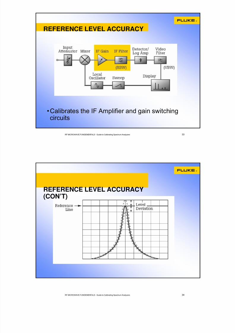
REFERENCE LEVEL ACCURACY
•Calibrates the IF Amplifier and gain switching
circuits
RF MICROWAVE FUNDEMENTALS - Guide to Calibrating Spectrum Analyzers 34
REFERENCE LEVEL ACCURACY(CON’T)

8/3/2019 Calibrating Spectrum Analyzer
http://slidepdf.com/reader/full/calibrating-spectrum-analyzer 18/33
RF MICROWAVE FUNDEMENTALS - Guide to Calibrating Spectrum Analyzers 35
REFERENCE LEVEL ACCURACY(CON’T)
•Test Setup
RF MICROWAVE FUNDEMENTALS - Guide to Calibrating Spectrum Analyzers 36
REFERENCE LEVEL ACCURACY (CON’T)
•Factors affecting Reference Level Accuracy – Accuracy of the Step Attenuator
– Mismatches
– Resolution of the Spectrum Analyzer Display

8/3/2019 Calibrating Spectrum Analyzer
http://slidepdf.com/reader/full/calibrating-spectrum-analyzer 19/33
RF MICROWAVE FUNDEMENTALS - Guide to Calibrating Spectrum Analyzers 37
NOISE SIDEBAND TEST
RF MICROWAVE FUNDEMENTALS - Guide to Calibrating Spectrum Analyzers 38
NOISE SIDEBAND TEST (CON’T)

8/3/2019 Calibrating Spectrum Analyzer
http://slidepdf.com/reader/full/calibrating-spectrum-analyzer 20/33
RF MICROWAVE FUNDEMENTALS - Guide to Calibrating Spectrum Analyzers 39
NOISE SIDEBAND TEST (CON’T)
•Test Setup
RF MICROWAVE FUNDEMENTALS - Guide to Calibrating Spectrum Analyzers 40
NOISE SIDEBAND TEST (CON’T)
• Verifies that the noise levels at frequency offsets above andbelow the carrier signal drop off rapidly enough to fall withinthe specified limits
• Important to ensure that the signal generator used in this test
is known to have low phase noise• Can be expressed in dBc or dBc/Hz which shows thesideband noise level normalized to a rectangular 1-Hzbandwidth

8/3/2019 Calibrating Spectrum Analyzer
http://slidepdf.com/reader/full/calibrating-spectrum-analyzer 21/33
RF MICROWAVE FUNDEMENTALS - Guide to Calibrating Spectrum Analyzers 41
NOISE SIDEBAND TEST (CON’T)
• Factors affecting Noise Sideband Test – Display linearity of the Spectrum Analyzer
– Resolution of the Spectrum Analyzer display – Amplitude modulation noise of the Spectrum Analyzer
– Uncertainty of the 3dB filter bandwidth
– Amplitude modulation noise of the generator signal
– Noise sideband of the signal generator
RF MICROWAVE FUNDEMENTALS - Guide to Calibrating Spectrum Analyzers 42
RESIDUAL FM TEST
8/3/2019 Calibrating Spectrum Analyzer
http://slidepdf.com/reader/full/calibrating-spectrum-analyzer 22/33
RF MICROWAVE FUNDEMENTALS - Guide to Calibrating Spectrum Analyzers 43
RESIDUAL FM TEST (CON’T)
RF MICROWAVE FUNDEMENTALS - Guide to Calibrating Spectrum Analyzers 44
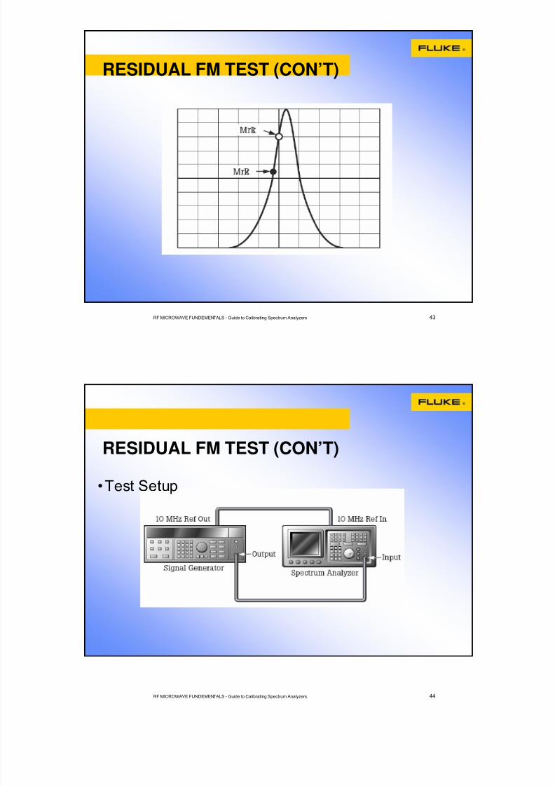
RESIDUAL FM TEST (CON’T)
•Test Setup

8/3/2019 Calibrating Spectrum Analyzer
http://slidepdf.com/reader/full/calibrating-spectrum-analyzer 23/33
RF MICROWAVE FUNDEMENTALS - Guide to Calibrating Spectrum Analyzers 45
RESIDUAL FM TEST (CON’T)
• measures the residual FM caused by inherent short-term
instability of the analyzer’s local oscillator system• uses the linear part of the analyzer’s IF filter response asan FM demodulator
• Factors affecting Residual FM Test – Display linearity of the spectrum analyzer
– Resolution of the spectrum analyzer display
– The residual FM of the signal generator
– Uncertainty of the frequency span as tested
– Nonlinearity of the IF filter response
RF MICROWAVE FUNDEMENTALS - Guide to Calibrating Spectrum Analyzers 46
FREQUENCY SPAN TEST

8/3/2019 Calibrating Spectrum Analyzer
http://slidepdf.com/reader/full/calibrating-spectrum-analyzer 24/33
RF MICROWAVE FUNDEMENTALS - Guide to Calibrating Spectrum Analyzers 47
FREQUENCY SPAN TEST(CON’T)
RF MICROWAVE FUNDEMENTALS - Guide to Calibrating Spectrum Analyzers 48
FREQUENCY SPAN TEST(CON’T)
•Test Setup

8/3/2019 Calibrating Spectrum Analyzer
http://slidepdf.com/reader/full/calibrating-spectrum-analyzer 25/33
RF MICROWAVE FUNDEMENTALS - Guide to Calibrating Spectrum Analyzers 49
FREQUENCY SPAN TEST(CON’T)
•determines the accuracy of the analyzer’s frequencyspan
•test the linearity of the analyzer display’s frequencyaxis
•Factors affecting Frequency Span Test – Resolution of the spectrum analyzer display and maker readout
– Frequency accuracy of the synthesizer
RF MICROWAVE FUNDEMENTALS - Guide to Calibrating Spectrum Analyzers 50
SWEEP TIME ACCURACY TEST

8/3/2019 Calibrating Spectrum Analyzer
http://slidepdf.com/reader/full/calibrating-spectrum-analyzer 26/33
RF MICROWAVE FUNDEMENTALS - Guide to Calibrating Spectrum Analyzers 51
SWEEP TIME ACCURACY TEST(CON’T)
RF MICROWAVE FUNDEMENTALS - Guide to Calibrating Spectrum Analyzers 52
SWEEP TIME ACCURACY TEST(CON’T)
•Test Setup

8/3/2019 Calibrating Spectrum Analyzer
http://slidepdf.com/reader/full/calibrating-spectrum-analyzer 27/33
RF MICROWAVE FUNDEMENTALS - Guide to Calibrating Spectrum Analyzers 53
SWEEP TIME ACCURACY TEST(CON’T)
•Sweep Time = (1/f FG )• (number of cycles of
waveform)•Factors affecting Sweep Time Accuracy Test
– Resolution of the spectrum analyzer display
– Frequency accuracy of the function generator
RF MICROWAVE FUNDEMENTALS - Guide to Calibrating Spectrum Analyzers 54
HARMONIC DISTORTION TEST

8/3/2019 Calibrating Spectrum Analyzer
http://slidepdf.com/reader/full/calibrating-spectrum-analyzer 28/33
RF MICROWAVE FUNDEMENTALS - Guide to Calibrating Spectrum Analyzers 55
HARMONIC DISTORTION TEST(CON’T)
RF MICROWAVE FUNDEMENTALS - Guide to Calibrating Spectrum Analyzers 56
HARMONIC DISTORTION TEST(CON’T)
•Test Setup

8/3/2019 Calibrating Spectrum Analyzer
http://slidepdf.com/reader/full/calibrating-spectrum-analyzer 29/33
RF MICROWAVE FUNDEMENTALS - Guide to Calibrating Spectrum Analyzers 57
HARMONIC DISTORTION TEST(CON’T)
• verifies that any unwanted harmonic distortion generatedwithin the analyzer is within the specified limits
• Factors affecting Harmonic Distortion Test – Harmonic content of the test signal
– Uncertainty of the reference level
– Display linearity of the spectrum analyzer
– Resolution of the spectrum analyzer display
– Signal-to-noise ratio
RF MICROWAVE FUNDEMENTALS - Guide to Calibrating Spectrum Analyzers 58
THIRD ORDER INTERMODULATIONINTERCEPT TEST

8/3/2019 Calibrating Spectrum Analyzer
http://slidepdf.com/reader/full/calibrating-spectrum-analyzer 30/33
RF MICROWAVE FUNDEMENTALS - Guide to Calibrating Spectrum Analyzers 59
THIRD ORDER INTERMODULATIONINTERCEPT TEST (CON’T)
RF MICROWAVE FUNDEMENTALS - Guide to Calibrating Spectrum Analyzers 60
THIRD ORDER INTERMODULATIONINTERCEPT TEST (CON’T)
•Test Setup

8/3/2019 Calibrating Spectrum Analyzer
http://slidepdf.com/reader/full/calibrating-spectrum-analyzer 31/33
RF MICROWAVE FUNDEMENTALS - Guide to Calibrating Spectrum Analyzers 61
THIRD ORDER INTERMODULATIONINTERCEPT TEST (CON’T)
• the mixer generate unwanted intermodulation if two signalsare present simultaneously at the spectrum analyzer input
• amount of intermodulation produced is described by theIntermodulation Intercept figure
• Together with the results of the noise floor test, theintermodulation intercept test will determine the dynamicrange of the spectrum analyzer
• third order intermodulation intercept, TOI = RL+(IR3/2)
RF MICROWAVE FUNDEMENTALS - Guide to Calibrating Spectrum Analyzers 62
THIRD ORDER INTERMODULATIONINTERCEPT TEST (CON’T)
•Factors affecting Third Order IntermodulationIntercept Test
– Resolution of the spectrum analyzer display
– Display linearity of the spectrum analyzer
– Uncertainty of the reference level – Intermodulation rejection of the signal generators combined with the
power coupler

8/3/2019 Calibrating Spectrum Analyzer
http://slidepdf.com/reader/full/calibrating-spectrum-analyzer 32/33
RF MICROWAVE FUNDEMENTALS - Guide to Calibrating Spectrum Analyzers 63
GAIN COMPRESSION TEST
RF MICROWAVE FUNDEMENTALS - Guide to Calibrating Spectrum Analyzers 64
GAIN COMPRESSION TEST(CON’T)

8/3/2019 Calibrating Spectrum Analyzer
http://slidepdf.com/reader/full/calibrating-spectrum-analyzer 33/33
RF MICROWAVE FUNDEMENTALS - Guide to Calibrating Spectrum Analyzers 65
GAIN COMPRESSION TEST(CON’T)
•Test Setup
GAIN COMPRESSION TEST(CON’T)
• Determines how well the spectrum analyzer can measurelow amplitude signals in the presence of high amplitudesignals
• Require two signal generators, a power meter to leveleach source and a coupler to introduce both signalssimultaneous to the spectrum analyzer input
• Factors affecting Gain Compression Test – Resolution of the spectrum analyzer display
– Display linearity of the spectrum analyzer
– Uncertainty of the reference level