calculation 2007-13241 (rev. 1) minimum wall thickness for esw buried … · 2012-12-01 ·...
TRANSCRIPT

Attachment Ito ULNRC-05542
Calculation 2007-13241 (Rev. 1)Minimum Wall Thickness for ESW Buried HDPE Piping

Calculation 2007-13241Revision 1
Page 1 of 17ISSUE SUMMARY
Form SOP-0402-07, Revision 7B
DESIGN CONTROL SUMMARYCLIENT: AmerenUE UNIT.NO.: 1 Page No.: 1PROJECT NAME: Callaway Nuclear PlantPROJECT NO.: 11504-025 Z NUCLEAR SAFETY- RELATED
CALC. NO.: 2007-13241 E NOT NUCLEAR SAFETY-RELATED
TITLE: Minimum Wall Thickness for ESW Buried HDPE Piping
EQUIPMENT NO.:
IDENTIFICATION OF PAGES ADDED/REVISED/SUPERSEDEDNVOIDED & REVIEW METHODINITIAL ISSUE
See Limitations in Section 6.3 INPUTS/ ASSUMPTIONS
[ VERIFIEDE UNVERIFIED
REVIEW METHOD: Detailed Review REV. 0STATUS: Approved DATE FOR REV.: 7128108PREPARER M. Tam (See Rev. 0 for Signatures/Dates) DATE:
PREPARER T. Musto (Section 6.4) (See Rev. 0 for Signatures/Dates) DATE:
REVIEWER J. Saltarelli (See Rev. 0 for Signatures/Dates) DATE:
APPROVER T. Musto (See Rev. 0 for Signatures/Dates) DATE:
IDENTIFICATION OF PAGES ADDED/REVISED/SUPERSEDED/VOIDED & REVIEW METHODRevision 1:Revised to incorporate updated design pressures, updated design code, and add results (forinformation only) considering a Design Factor value of 0.56. Revised pages 1 - 14 and addedpages 15 - 17. Deleted Attachments 1 and 2 from Rev 0, and added Attachment 1 for AmerenUE INPUTS/ ASSUMPTIONS
Owner's Review Comments. [ VERIFIED
E UNVERIFIED
REVIEW METHOD: Detailed Review REV. 1STATUS: Approved DATE FOR REV.: Oq/ojrt)8PREPARER J. Patel _ DATE:. Os totREVIEWER J. Saltarelli DATE:APPROVER T. Musto DATE: o0!L&i a0
IDENTIFICATION OF PAGES ADDED/REVISED/SUPERSEDEDNOIDED & REVIEW METHOD
INPUTS/ ASSUMPTIONS
E VERIFIED
[] UNVERIFIED
REVIEW METHOD: REV.STATUS: DATE FOR REV.:PREPARER DATE:
REVIEWER DATE:
APPROVER DATE:
NOTE: PRINT AND SIGN IN THE SIGNATURE AREAS
SOP040207.DOCRev. Date: 11-12-2007
Page 1 of 1

Calculation 2007-13241Revision 1
Page 2 of 17
TABLE OF CONTENTS
1.0 PURPOSE AND SCOPE ................................................................................. 3
2.0 DESIGN INPUTS .............................................................................................. 4
3.0 ASSUM PTIONS 6................................................................................................... 6
4.0 METHODOLOGY AND ACCEPTANCE CRITERIA .......................................... 7
5.0 CALCULATIONS ............................................................................................. 10
6.0 RESULTS ............................................................................................................ 14
7.0 REFERENCES ................................................................................................. 17
8.0 ATTACHM ENTS ............................................................................ .: ................ 17

Calculation 2007-13241Revision 1
Page 3 of 17
1.0 PURPOSE AND SCOPE
The purpose of this calculation is to determine the minimum required wall thickness forthe Callaway.Nuclear Plant ESW buried High Density Polyethylene (HDPE) supply,return, and strainer backwash straight piping that is to replace the currently existingburied carbon steel piping under modification number MP 07-0066 [Ref. 7.2.1]. Thiscalculation does not apply to fittings and components.
Specifically, this calculation applies to the following line numbers:
EF-002-AZC-4" - ESW Train WA' Strainer Backwash LineEF-003-AZC-36" - ESW Train 'A' Supply from ESW PumphouseEF-006-AZC-4" - ESW Train 'B' Strainer Backwash LineEF-007-AZC-36" - ESW Train 'B' Supply from ESW PumphouseEF-083-AZC-36" - ESW Train 'A' Return to UHS Cooling TowerEF-140-AZC-36' - ESW Train 'B' Return to UHS Cooling Tower

Calculation 2007-13241Revision 1
Page 4 of 17
2.0 DESIGN INPUTS
2.1 ESW HDPE Supply Lines
Internal design pressure (PD) = 161 psig [Ref. 7.2.1]
Design temperature (TD) = 95°F [Ref. 7.2.1]
Outside diameter of pipe (D) = 36" [Ref. 7.2.1]
Piping Material: PE 4710 with material properties not less than those for cellclassification 445574C as defined by ASTM D3350 [Ref. 7.2.1]
2.2 ESW HDPE Return Lines
Internal design pressure (PD) = 45 psig [Ref. 7.2.1]
Design temperature (TD) = 175 0F [Ref. 7.2.1]
Normal Operating Temperature (T,) = 105 0F [Ref. 7.2.8]
Outside diameter of pipe (D) = 36" [Ref. 7.2.1]
Piping Material: PE 4710 with material properties not less than those for cellclassification 445574C as defined by ASTM D3350 [Ref. 7.2.1]
2.3 ESW HDPE Backwash Lines
Internal design pressure (PD) = 160 psig [Ref. 7.2.1]
Design temperature (TD) = 950F [Ref. 7.2.1]
Outside diameter of pipe (D) = 4.5" [Ref. 7.2.1]
Piping Material: PE 4710 with material properties not less than those for cellclassification 445574C as defined by ASTM D3350 [Ref. 7.2.1]
2.4 Design Code
The design is in accordance with procedure APA-ZZ-00662, Appendix F [Ref. 7.1.1] perDesign Specification M-2017 [Ref 7.2.2].
2.5 Mechanical and Erosion Allowance
No mechanical or erosion allowance (C) is considered in the minimum wall thicknesscalculation (See Assumption 3.1) [Ref. 7.2.4, p. 8].

Calculation 2007-13241Revision 1
Page 5 of 17
2.6, Normal Service Life
The replacement buried piping shall be designed for a service life of 40 years undernormal system operating conditions as stated in Reference 7.2.2, Section 6.1.1.
2.7 Post-Accident Service Life
The replacement buried piping shall be designed for a service life of 30 days at peakpost-accident system operating conditions. The design shall assume that the peak post-accident conditions occur continuously for the entire 30 day period and that the accidentoccurs at the end of the 40 year normal service life as stated in Reference 7.2.2, Section6.1.2.
2.8 Allowable Stress
Allowable stress values for HDPE for Design Factors 0.50 and.0.56 are taken fromprocedure APA-ZZ-00662, Appendix F [Ref. 7.1.1] and are listed below in Table 2.8-1and Table 2.8-2 below respectively. In accordance with -3016 of procedure APA-ZZ-00662, Appendix F [Ref. 7.1.1], a Design Factor of 0.50 shall be utilized. A DesignFactor of 0.56 is used in this calculation for information only. The use of these values forCallaway Nuclear Plant still requires formal acceptance by the NRC (Limitation 6.3.1).
Table 2.8-1 - Allowable Stress for Design Factor of 0.50Service Temp. (OF) Load Duration (yrs) Allowable Stress (psi)
95°F 5 50 6951040F -- 50 653113 0F !5 50 6131760F 2 340
Table 2.8-2 - Allowable Stress for Design Factor of 0.56 (For Information Only)Service Temp. (OF) Load Duration (yrs) Allowable Stress (psi)
95°F -< 50 7781040F -< 50 732113 0F _< 50 6871760F 2 382
Note: While Reference 7.1.1 only provides values for a load duration of 50 years, thesevalues can conservatively be used for load durations of less than 50 years.

Calculation 2007-13241Revision 1
Page 6 of 17
3.0 ASSUMPTIONS
3.1 Assumption: No mechanical or erosion allowance (C) is considered in the minimumwall thickness calculation.
Justification:HDPE pipe will not rust, rot, pit, corrode, tuberculate or support biological growth. It hassuperb chemical resistance and is the material of choice for many harsh chemicalenvironments [Ref. 7.2.4, p. 8]. Therefore, no mechanical or erosion allowance isrequired. This is consistent with Reference 7.2.2, Section 6.2.
3.2 Assumption: The allowable stress value for the HDPE Return Lines for a post-accidentcondition service life of 30 days is 340 psi at 1751F for a Design Factor of 0.50.
Justification:The only allowable stress value data available near 175 0F is 340 psi at 176 0F for a loadduration of 2 years in Reference 7.1.1 [Design Input 2.8]. The allowable stress for 2years is lower than the allowable stress for 30 days and the allowable stress at 1760F islower than the allowable stress at 175 0F. This will result in a larger minimum wallthickness for the 30 day post-accident condition service life case at 175 0F for the HDPEReturn Lines. Therefore, it is conservative to use 340 psi.
For Information Only:
3.3 Assumption: The allowable stress value for the HDPE Return Lines for a post-accidentcondition service life of 30 days is 382 psi at 175°F for a Design Factor of 0.56.
Justification:The only allowable stress value data available near 1750F is 382 psi at 176 0F for a loadduration of 2 years in Reference 7.1.1 [Design Input 2.8]. The allowable stress for 2years is lower than the allowable stress for 30 days and the allowable stress at 176 0F islower than the allowable stress at 175 0F. This will result in a larger minimum wallthickness for the 30 day post-accident condition service life case at 175°F for the HDPEReturn Lines. Therefore, it is conservative to use 382 psi.

Calculation 2007-13241Revision 1
Page 7 of.17
4.0 METHODOLOGY AND ACCEPTANCE CRITERIA
4.1 Methodology
4.2 Allowable Stress for HDPE Return Lines
Since the allowable stress value at a design temperature of 175°F for the HDPE ReturnLines has only been provided for a maximum load duration of 2 years in Reference7.1.1, an allowable stress value is calculated for the Normal Operating Condition case asdefined by Miner's Rule using the methodology in Sections 4.2.1 and 4.2.2 and 340 psifor the 30 day Post-Accident Condition case (See Assumption 3.2) for a Design Factor of0.50, and 382 psi for the 30 day Post-Accident Condition case (See Assumption 3.3) fora Design Factor of 0.56. A minimum wall thickness will be calculated for both the NormalOperating Condition and the 30 day Post-Accident Condition and the larger of the twoshall be conservatively used for the HDPE Return Lines.
4.2.1 Miner's Rule to Calculate Load Duration
Miner's Rule takes into consideration the damages done to the pipe under differentoperating conditions to calculate the cumulative maximum permissible time of use underall varying conditions of the pipe. For the HDPE return lines, Normal OperatingConditions and Post-Accident Operating Conditions are considered. The cumulativemaximum permissible time of use is the design service life of 40 years.
To calculate the allowable stress value for Normal Operating Conditions, Miner's Rulefor plastic pipe [Ref. 7.2.6] is used, as specified in Reference 7.1.1, to find the loadduration for the pipe under normal operating conditions that will ensure a cumulativemaximum permissible time of use of 40 years when considering the 30 day load durationat Post-Accident Operating Conditions; This load duration can then be used tointerpolate a corresponding allowable stress value using the values in Reference 7.1.1 atthe normal operating temperature of 105 0F. The allowable stress value for a loadduration of_< 50 years at 105 0F is provided in Reference 7.1.1 [Design Input 2.8]. Thefollowing variables are used.by Miners Rule:
To = normal operating temperature (OF)T,,a, = maximum operating temperature (post-accident temperature) (OF)Ai = percent of total service life of pipe under condition "i" (i=1, 2, 3, etc.) (%)ti = lifetime of pipe if placed under condition "i" (yrs)tra× = lifetime of pipe if placed under maximum operating temperature Tmax (yrs)to = lifetime of pipe if placed under normal operating temperature T, (yrs)tx = maximum permissible time of use under all varying conditions (yrs)TYD = total yearly damage (%)
The percent of total service life of the pipe under each condition "i" is calculated for i=1,2, 3, etc.
Aj - Time Under Condition 'Ti (yrs)Total Service Life of Pipe (yrs)

Calculation 2007-13241Revision 1
Page 8 of 17
Each condition which the pipe is exposed to generates a yearly damage percentage onthe pipe.
Yearly Damage = A- = Percent of Total Service Life of Pipe Under Condition i" (%)tj Lifetime of Pipe Under Condition "i" (yrs)
The summation of these yearly damages is the total yearly damage.
TYD = A_ti
The total yearly damage (TYD) is used to find the maximum permissible time of useunder all varying conditions.
100TYD
To find the load duration for the pipe under normal operation, Miner's Rule is rearrangedto solve for to, the lifetime of pipe if placed under only the normal operating temperatureTo = 105'F. This duration will be longer than t,, the maximum permissible time of useunder all varying conditions, and will provide a lower allowable stress value. Therefore,the minimum wall thickness calculated using this value for allowable stress for NormalOperating Conditions will result in a larger minimum wall thickness which isconservative.
First, solve for the percent of the total service life of the pipe that is exposed to thenormal operating temperature and the post-accident temperature to obtain A, and Amax
respectively. Then calculate the yearly damage percentages on the pipe from theNormal Operating and Post-Accident Condition where to is the Unknown variable to solvefor and tmax is 2 years as stated in Assumption 3.2 and 3.3.
yearly damage from post - accident condition- Amaxtmax
yearly damage from normal operating condition =Ato
Summate the yearly damages to obtain the total yearly damage as a function of t°.
TYD= Ai A0 Amaxti o tmax
With the maximum permissible time of use under all varying conditions set as 40 years,tx = 40 years, substitute the TYD and solve for to.
=100 40 100
TYD A0 Armax+to t max

Calculation 2007-13241Revision 1
Page 9 Of 17
4.2.2 Interpolation for Allowable Stress Values for Normal Operating Condition Case ofthe HDPE Return Lines Using the Calculated Load Duration (to)
To determine the allowable stress values for the Normal Operating Condition case,interpolate between the load durations of 50 years and the calculated t, load duration.
4.3 Minimum Wall Thickness
The required minimum wall thickness is determined for the pipe lines identified inSection 1.0 of this calculation. The required minimum wall thickness (tdes~in) is calculatedin accordance with procedure APA-ZZ-00662, Appendix F [Ref. 7.1.1] per DesignSpecification M-2017 [Ref 7.2.2] as follows:
POD ,tdesign - 2S + P C
tmin
where:tdesign = minimum required wall thickness (in)tmin = pressure design thickness (in)C = the sum of mechanical allowances and-erosion allowance (in)PD = piping system internal Design Pressure (gage) at the corresponding Design
Temperature TD. This pressure does not include the consideration of pressurespikes due to transients (psig)
D = pipe outside diameter at the pipe section where the evaluation is conducted (in)S = allowable stress (psi)
4.4 Acceptance Criteria
None

Calculation 2007-13241Revision 1
Page 10 of 17
5.0 CALCULATIONS
5.1 Calculation of Normal and Post-Accident Condition Allowable Stresses Values forHDPE Return Lines
5.1.1 Percent of total service life of the pipe under each condition.
A 40years - 30days(post-accident) 39.92years 1 00 % = 99.8%40years
Amax 30days(post-accident) = 0.08years x1 00% = 0.2%40years
5.1.2 Summate the yearly damages to obtain the total yearly damage as a function of to.
A 99.8% 0.2%T'YD=E" -- 2y- rstj to 2years
5.1.3 Substitute the TYD and solve fort,.
100 100t TYD -+40years= 99.8% 0.2% t= 41.58 years
to 2years
5.1.4 Interpolate between temperatures of 11 3F and 1040F to find the allowable stress valueSlo5oFat 105°F and 50 years from Design Input 2.8 for a Design Factor of 0.50.
1050 F = (613 psi- 653 psi)(1050 F - 1040F)+ 653 psi = 648.6 psi
(113 0F -104 0 FY
For Information Only:
Interpolate between temperatures of 11 30F and 104°F to find the allowable stress valueSlo5-Fat 105 0F and 50 years from Design Input 2.8 for a Design Factor of 0.56.
S (687 Psi - 732 Psi) (105F 1040F)+ 732 psi = 72 7 psiS05(F 113 0F -104-F)
Calculation 2007-13241Revision 1
Page 11 of 17
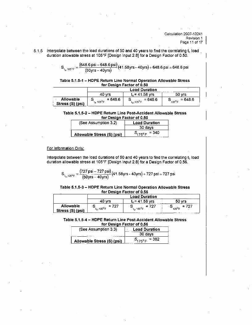
5.1.5 Interpolate between the load durations of 50 and 40 years to find the correlating t, loadduration allowable stress at 105 0F [Design Input 2.8] for a Design Factor of 0.50.
S t, 10 50F. (648.6 psi - 648.6 psi) (41.58yrs - 40yrs) + 648.6 psi = 648.6 psi(50yrs - 40yrs)
Table 5.1.5-1 - HDPE Return Line Normal Operation Allowable Stressfor Design Factor of 0.50
Load Duration40 yrs to = 41.58 yrs 50 yrs
Allowable S = 648.6 S = 648.6 S = 648.6Stress (S) (psi) t'OF tO°F
Table 5.1.5-2 - HDPE Return Line Post-Accident Allowable Stressfor Design Factor of 0.50
(See Assumption 3.2) Load Duration30 days
Allowable Stress (S) (psi) S17 5 0F = 340
For Information Only:
Interpolate between the load durations of 50 and 40 years to find the correlating t, loadduration allowable stress at 105°F [Design Input 2.8] for a Design Factor of 0.56.
St,105*F = (727 psi - 727 psi) (41 58yrs - 40yrs) + 727 psi = 727 psi(50yrs - 40yrs)
Table 5.1.5-3 - HDPE Return Line Normal Operation Allowable Stressfor Design Factor of 0.56
Load Duration40 yrs to= 41.58 yrs 50 yrs
Allowable S = 727 S = 727 S15F= 727Stress (S) (psi) tx,1 0 F t°,1050F 105°F
Table 5.1.5-4 - HDPE Return Line Post-Accident Allowable Stressfor Design Factor of 0.56
(See Assumption 3.3) Load Duration30 days
Allowable Stress (S) (psi) S175°F = 382

Calculation 2007-13241Revision 1
Page 12 of 17
5.2 Minimum Calculated Wall Thicknesses
5.2.1 Supply Lines
Under an internal design pressure of 161 psig (Design Input 2.1), design temperature of95°F (Design Input 2.1), mechanical and erosion allowance of 0" (Design Input 2.5),allowable stress of 695 psi (Table 2.8-1) for both supply lines at a Design Factor of 0.50,and an allowable stress of 778 psi (Table 2.8-2) for both supply lines at a Design Factorof 0.56 (for information only), the PE 4710 36" diameter ESW HDPE supply line pipingminimum required wall thickness is:
Desigqn Factor of 0.50:
tdesign supply (161psigX36#) +0=3.737'2(695psi) + 16 lpsig
Design Factor of 0.56 (For Information Only):(161psigX36") . 0=3.376"
desgn, supply 2(778psi) + 16 1psig
5.2.2 Return Lines
5.2.2.1 For the Normal Operating Conditions case, an internal design pressure of 45 psig(Design Input 2.2), design temperature of 105°F (Design Input 2.2), mechanical anderosion allowance of 0" (Design Input 2.5), allowable stress of 648.6 psi (Table 5.1.5-1)for both return lines at a Design Factor of 0.50, and an allowable stress of 727 psi (Table5.1.5-3) for both return lines at a Design Factor of 0.56 (for information only), the PE4710 36" diameter ESW HDPE return line piping minimum required wall thickness is:
Design Factor of 0.50:
tdesignreturnnor . - (45psigX36") +0=1.21'return, normal op. 2(648.6psi) + 45psig
Desigqn Factor of 0.56 (For Information Only):
(45psigX36") + 0 = 1.081"design, return, normal op 2(727psi) + 45psig
Calculation 2007-13241Revision 1
Page 13 of 17
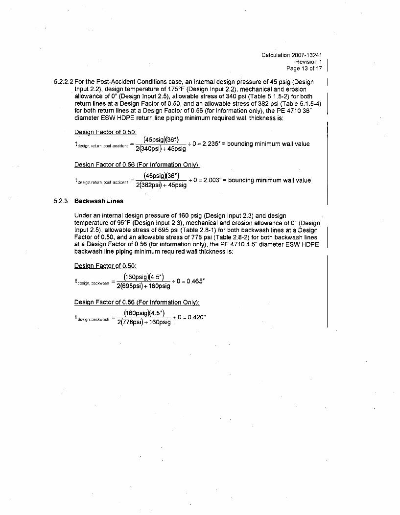
5.2.2.2 For the Post-Accident Conditions case, an internal design pressure of 45 psig (DesignInput 2.2), design temperature of 175°F (Design Input 2.2), mechanical and erosionallowance of 0" (Design Input 2.5), allowable stress of 340 psi (Table 5.1.5-2) for bothreturn lines at a Design Factor of 0.50, and an allowable stress of 382 psi (Table 5.1.5-4)for both return lines at a Design Factor of 0.56 (for information only), the PE 4710 36"diameter ESW HDPE return line piping minimum required wall thickness is:
Design Factor of 0.50:
tdesign, return, post-accident = (45psigX36") + 0 = 2.235' = bounding minimum wall valueretrn pstacidnt2(34Opsi) + 45psig
Design Factor of 0.56 (For Information Only):
tdesign, return postaccident (4545pgs36g) + 0 = 2.003" = bounding minimum wall valuet •sinreur, es-acien =2(382psi) + 45psig
5.2.3 Backwash Lines
Under an internal design pressure of 160 psig (Design Input 2.3) and designtemperature of 95 0F (Design Input 2.3), mechanical and erosion allowance of 0" (DesignInput 2.5), allowable stress of 695 psi (Table 2.8-1) for both backwash lines at a DesignFactor of 0.50, and an allowable stress of 778 psi (Table 2.8-2) for both backwash linesat a Design Factor of 0.56 (for information only), the PE 4710 4.5" diameter ESW HDPEbackwash line piping minimum required wall thickness is:
Design Factor of 0.50:
tdesign backwash (160psigX4.5") + 0 = 0.465'2(695psi) + 160psig
Design Factor of 0.56 (For Information Only):
tdesign, backwash (160psigX4.5') + 0 = 0.420"2(778psi) + 160psig

Calculation 2007-13241Revision 1
Page 14 of 17
6.0 RESULTS
6.1 Results
The required minimum wall thicknesses for the ESW buried HDPE pipes at a DesignFactor of 0.50 are shown below in Table 6.1-1:
Table 6.1-1 - Summary of Results for Design Factor of 0.50Line No. Min. Wall
Thickness (in)EF-003-AZC-36" - ESW Train 'A' 3.737"Supply from ESW PumphouseEF-007-AZC-36" - ESW Train 'B' 3.737"Supply from ESW PumphouseEF-083-AZC-36" - ESW Train 'A' 2.235".Return to UHS Cooling TowerEF-140-AZC-36" - ESW Train 'B' 2.235"Return to UHS Cooling TowerEF-002-AZC-4" - ESW Train 'A' 0.465"Strainer Backwash LineEF-006-AZC-4" - ESW Train 'B' 0.465"Strainer Backwash Line
For Information Only:The required minimum wall thicknesses for the ESW buried HDPE pipes at a DesignFactor of 0.56 are shown below in Table 6.1-2:
Table 6.1-2 - Summary of Results for Design Factor of 0.56Line No. Min. Wall
Thickness (in)EF-003-AZC-36" - ESW Train 'A' 3.376"Supply from ESW PumphouseEF-007-AZC-36" - ESW Train 'B' 3.376"Supply from ESW PumphouseEF-083-AZC-36" - ESW Train 'A' 2.003"Return to UHS Cooling TowerEF-140-AZC-36" - ESW Train 'B' 2.003"Return to UHS Cooling TowerEF-002-AZC-4" - ESW Train 'A' 0.420"Strainer Backwash LineEF-006-AZC-4" - ESW Train 'B' 0.420"Strainer Backwash Line
6.2 ConclusionsThe required minimum calculated wall thickness values provided in Section 6.1 of thiscalculation apply to straight pipe only and include 0.0" mechanical and erosionallowance. Nominal wall thickness values for the applicable lines must account formanufacturing tolerances such that the as-manufactured minimum wall thickness valuesfor the piping are greater than or equal to the required values.

Calculation 2007-13241Revision 1
Page 15 of 17
6.3 Limitations
6.3.1 The required minimum wall thickness calculated within this calculation is based on themethodology and allowable stress values provided within procedure APA-ZZ-00662,Appendix F [Ref. 7.1.1]. The use of procedure APA-ZZ-00662, Appendix F [Ref. 7.1.1],still requires formal acceptance by the NRC.
6.3.2 The values based on a Design Factor of 0.56 within this calculation are provided forinformation only and are not to be used in the design of the piping system.

Calculation 2007-13241Revision 1
Page 16 of 17
6.4 Impact Assessment
The following sections identify the documents reviewed for impact by this calculation andsummarize the results of the impact assessments. Impacts as a result of the pipingreplacement being performed under MP 07-0066 are identified and evaluated as part ofMP 07-0066.
6.4.1 FSAR / Site Addendum
The following sections of the standard plant FSAR and site addendum were reviewed forimpact by this calculation:
3.9(B) (SP): Minimum wall thickness is not discussed in the FSAR for the design of non-NSSS piping. (NOT IMPACTED)
9.2 (SP and SA): This calculation does not change the design basis functions of theESW system, design conditions of the ESW piping or design heat loads acting on theESW system. (NOT IMPACTED)
6.4.2 Technical Specifications / Technical Specification Bases
The following sections of the technical specifications and technical specification baseswere reviewed for impact by this calculation:
3.7.8 / B 3.7.8: This calculation does not change any surveillance requirements for theESW system. None of the bases for the surveillance requirements are impacted. (NOTIMPACTED)
6.4.3 Other Documents
MS-02: A new material designation must be added to MS-02 for HDPE. This materialdesignation must ensure that the nominal wall thickness values of installed HDPE pipingwill provide actual minimum wall thickness values greater than or equal to the requiredminimum wall thickness values determined in this calculation. (IMPACTED)
6.4.4 Design and Operating Mar-gins
This calculation determines required minimum wall thickness for the subject replacementESW piping. The nominal wall thickness of the installed piping, and hence the marginbetween the as-manufactured minimum wall thickness and the required minimum wallthickness, will be identified in Section 2.3.8 of the Engineering Disposition for MP 07-0066.

Calculation 2007-13241Revision 1
Page 17 of 17
7.0 REFERENCES
7.1 Codes
7.1.1 Callaway Nuclear Plant Procedure APA-ZZ-00662, Appendix F, Rev. 4, "Requirementsfor High Density Polyethylene (HDPE) Piping for Nuclear Service."
7.2 Miscelianeous
7.2.1 Callaway Nuclear Plant Modification No. MP 07-0066, "Replace Buried ESW Piping withHDPE Material" including FCN 09. - 1
7.2.2 Callaway Nuclear Plant Design Specification No. M-2017, Rev.1, "Design Specificationfor Replacement ASME Section III Buried Essential Service Water System Piping"
7.2.3 Not Used
7.2.4 The Plastics Pipe Institute, Inc. "Handbook of Polyethylene Pipe", First Edition
7.2.5 Not Used
7.2.6 The International Organization for Standardization, ISO 13760:1998(E), "Plastics Pipesfor the Conveyance of Fluids Under Pressure - Miner's Rule - Calculation Method forCumulative Damage" (See Limitation 6.3.1)
7.2.7 Not Used
7.2.8 Callaway Nuclear Plant Document MS-01, Rev. 96, "Piping Class Summary"
8.0 ATTACHMENTS
1. Revision 1 AmerenUE Owner's Review Comments 2 Pages

Calculation 2007-13241Revision 1
Attachment 1Page 1 of 2
Attachment 1
Revision 1 AmerenUE Owner's Review Comments"

Callaway Comments Calculation 2007-13241on Revision 1
Minimum Wall Thickness for ESW Buried HDPE Piping, Attachment 1
S&L Calculation 2007-13241 Rev 1 (DRAFT) (received 8/19/08)) Page 2 of 2
Callaway comments dated 09/03108
Comment Caic. Section Comment Proposed Resolution1. 6.4.4 Specify where the margin between the as-manufactured Comment Incorporated.
minimum wall thickness and the required minimum wallthickness will be provided within MP 07-0066.
Page 1 of 1