cable laying requirements
DESCRIPTION
cable layingTRANSCRIPT
Version Prepaired by Approvded by
Issue Date
5.6 T Haggis & T Dutton M Simpson April 2010
Application Guide Reference CNAG 09-CL
Cable Laying Requirements
Issue date April 2010
Version 5.6
Pages 29
Purpose This Application Guide defines the technical requirements to be achieved by the cable installer together with the constraints necessary to ensure the integrity of the final installation.
Approved materials and other useful information is contained within the appendixes.
The cable installer shall be responsible for developing and maintaining method statements to install cables to meet the requirements of this Application Guide.
Scope This Specification refers to: Low Voltage Cables Medium Voltage (6.6kV, 11kV & 33kV) Cables used on Central Networks LV & MV Underground Network
Audience E.ON Central Networks, E.ON UK Business Services, E.ON Energy Services and their service providers and contractors.
Independent Connections Providers
Restrictions: None
Review Date 1 April 2013
Owner Network Standards
Related Documents • Central Networks Network Design Manual
• General Health & Safety Manual Section 18.4 “Arrangements on Safe Excavation”

CNAG 09-CL
Application Guide
Cable Laying Requirements
Version 5.6 Date of Issue – April 2010 Page 2 of 29
The current version of the this document resides in the E.ON UK Documentum database CAUTION – any other copy in electronic, printed or other formats may be out of date
© Central Networks plc
Revision Log
Version Prepared by Checked by Approved by Reviewed By Date 5.6 Tony Haggis
Senior Overhead Line Specialist
Terry Dutton Senior Cable Specialist
M Simpson N/A April 2010
Notes: 2.2.1 – Reference to General Health & Safety Manual Section 18.4 “Arrangements on Safe Excavation” 3.2 Protection of Cables by Ducts and Tapes – NEW CABLE PROTECTION POLICY INCLUDING LAID DIRECT AND SOLID WALL DUCT OPTIONS Appendix A2 – Laid Direct - Cables Laid Along Footpaths and PPG 3 Road/Footpaths NEW DRAWINGS APPENDIX H2 Transformer 33kV Tails – NEW APPENDIX ADDED Appendix I Technical details of Duct, Marker Tapes Tiles etc. – NEW APPENDIX ADDED
Changes made in version 5.5
Date Section Notes about the change 01/12/2006 All Cable Laying
Technical Requirements
Re-branded to E.ON Central Networks.
Changes made in version 5.4
Date Section Notes about the change 23/02/2006 All Cable Laying
Technical Requirements
Cable Laying Technical Requirements extracted from Cables & Cable Laying Accessories Manual as it now applies to both East and West and resides in COMBINED Central Networks. The Cables & Cable Laying Accessories Manual remains application to East only and resides in EAST Central Networks.
Changes made in version 5.3
Date Section Notes about the change 2/09/2005 32.1 Paragraph re-worded “All Central Networks’ cables installed in
the public environment shall be laid in black rigid corrugated ducts complying with ENATS 12-24 together with warning tape or tiles. Cables may be laid without ducts inside substations.”

CNAG 09-CL
Application Guide
Cable Laying Requirements
Version 5.6 Date of Issue – April 2010 Page 3 of 29
The current version of the this document resides in the E.ON UK Documentum database CAUTION – any other copy in electronic, printed or other formats may be out of date
© Central Networks plc
Changes made in version 5.1
Date Section Notes about the change 18/02/2005 31.2
32.3
Appendix A
Appendix C
Reference included to PPG3 residential sites Requirements for spacing between ducts for blinding / consolidation explained. Changed to read ‘Cables Laid Along Footpaths and PPG 3 Road/Footpaths’ Changed to read ‘Cables Laid Across and Along Roads’
Changes made in version 5
Date Section Notes about the change 10/11/2004 All
Appendices
A,B,C
Appendix H
Document modified to reflect adoption of ducting all cables. Duct cable drawings added Added showing spacing of 11kV transformer tails
Changes made in version 4
Date Section Notes about the change 24/11/2003 Section 1 22.1
Appendix G
Specification added to 33kV tiles. Joint hole dimensions & text amended.
Changes made in version 3
Date Section Notes about the change 13/11/2002 Paragraph 32.3
Appendices A,B &C
Appendix D Appendix G
Amendments to requirements for ducts, tapes & tiles due to introduction of Electricity Safety, Quality and Continuity Regulations 2002. Amendments to drawings showing changes as a result of Paragraph 32.3 Changes to duct size for 70mm2 Triplex 11kV cable. Contractors’ item codes removed (no longer needed).

CNAG 09-CL
Application Guide
Cable Laying Requirements
Version 5.6 Date of Issue – April 2010 Page 4 of 29
The current version of the this document resides in the E.ON UK Documentum database CAUTION – any other copy in electronic, printed or other formats may be out of date
© Central Networks plc
Changes made in version 2
Date Section Notes about the change May 2002 Section 32.3
Appendix G
Specification added to 33kV tiles. Joint hole dimensions & text amended.
Changes made in version 1
Date Section Notes about the change Feb 2001 Cable Laying
Technical Requirements
Cable Laying Technical Requirements added to Cables & Cable Laying Accessories Manual.
CNAG 09-CL
Application Guide
Cable Laying Requirements
Version 5.6 Date of Issue – April 2010 Page 5 of 29
The current version of the this document resides in the E.ON UK Documentum database CAUTION – any other copy in electronic, printed or other formats may be out of date
© Central Networks plc
CONTENTS
CONTENTS .................................................................................................................................. 5
1. INTRODUCTION .............................................................................................................. 7
2. EXCAVATION ................................................................................................................... 7
2.1 Signing & Guarding ..................................................................................................... 7
2.2 Excavation ...................................................................................................................... 8
2.3 Reinstatement ................................................................................................................. 8
3. CABLE INSTALLATION ................................................................................................. 8
3.1 Depth & Spacing ........................................................................................................... 8
3.2 Protection of Cables by Ducts and Tapes .............................................................. 9
3.3 Pulling in cables .......................................................................................................... 14
4. EARTHING AND BONDING OF SINGLE CORE CABLES ........................................ 15
4.1 LV Cables ..................................................................................................................... 15
4.2 Three Core Cables ....................................................................................................... 15
4.3 Single Core Cables ....................................................................................................... 15
APPENDIX A1 - DUCTED .................................................................................................... 17
Cables Laid Along Footpaths and PPG 3 Road/Footpaths ........................................ 17
APPENDIX A2 – LAID DIRECT ........................................................................................... 18
Cables Laid Along Footpaths and PPG 3 Road/Footpaths ........................................ 18
APPENDIX B .......................................................................................................................... 19

CNAG 09-CL
Application Guide
Cable Laying Requirements
Version 5.6 Date of Issue – April 2010 Page 6 of 29
The current version of the this document resides in the E.ON UK Documentum database CAUTION – any other copy in electronic, printed or other formats may be out of date
© Central Networks plc
Cable Laid in Agricultural Land ........................................................................................ 19
APPENDIX C ......................................................................................................................... 20
Cables Laid Across and Along Roads ........................................................................... 20
APPENDIX D .......................................................................................................................... 21
Standard Duct Sizes ............................................................................................................ 21
APPENDIX E ......................................................................................................................... 22
Minimum Bending Radii .................................................................................................... 22
APPENDIX F ......................................................................................................................... 23
Mechanical Pulling-in Tensions ....................................................................................... 23
APPENDIX G ......................................................................................................................... 24
Joint Hole Dimensions ....................................................................................................... 24
APPENDIX H1 ....................................................................................................................... 25
Transformer 11kV Tails ...................................................................................................... 25
APPENDIX H2 ....................................................................................................................... 26
Transformer 33kV Tails ...................................................................................................... 26
APPENDIX I ........................................................................................................................... 27
Technical details of Duct, Marker Tapes Tiles etc. ..................................................... 27
CNAG 09-CL
Application Guide
Cable Laying Requirements
Version 5.6 Date of Issue – April 2010 Page 7 of 29
The current version of the this document resides in the E.ON UK Documentum database CAUTION – any other copy in electronic, printed or other formats may be out of date
© Central Networks plc
TECHNICAL REQUIREMENTS: Cable Laying
1. Introduction 1.1.1 This Application Guide defines the technical requirements to be achieved by the
cable installer together with the constraints necessary to ensure the integrity of the final installation.
1.1.2 The cable installer shall be responsible for developing and maintaining method statements to install cables to meet the requirements of this Application Guide.
1.1.3 Central Networks may approve or reject the cable installer’s method statements in accordance with the provisions of the Contract.
2. Excavation 2.1 Signing & Guarding
2.1.1 Public highway All Works carried out shall comply with:
1. New Roads and Street Works Act 1991 “Safety at Street Works and Road Works” code of practice.
2. “Chapter 8 of the Traffic Signs Manual” published by the Dept. of Transport.
2.1.2 Private land
All works carried out shall be protected to the same degree as 21.1 unless otherwise agreed by the landowner.
2.1.3 Agricultural land In addition to 21.1 and 21.2 the Cable Installer may use electric fencing to protect livestock from the Works provided that:
• The Cable Installer obtains permission from the owner of the livestock and the landowner or tenant.
• The electric fencing displays warning signs at a minimum of every 2 meters.
2.1.4 Courtesy Boards A the Cable Installer shall provide and display a courtesy board at each Site showing:
• the Cable Installer’s name • Central Networks’ name and 24 hour telephone number
CNAG 09-CL
Application Guide
Cable Laying Requirements
Version 5.6 Date of Issue – April 2010 Page 8 of 29
The current version of the this document resides in the E.ON UK Documentum database CAUTION – any other copy in electronic, printed or other formats may be out of date
© Central Networks plc
• An approved apology message on behalf of Central Networks.
2.2 Excavation 2.2.1 Safe Excavation
Operatives shall be conversant with Central Networks General Health & Safety Manual Section 18.4 “Arrangements on Safe Excavation”. Prior to excavation the Cable Installer shall consult the plans of all utilities plant and then confirm their position by use of suitable instruments. Important Note. Cables belonging to Independent Distribution Network Operators (IDNO) are now present in many locations alongside Central Networks cables. IDNO cables are NOT SHOWN on Central Networks records. The Cable Installer will need to obtain cable records from the IDNOs operating networks in the locality.
2.2.2 Excavation shall be carried out in accordance with the “HAUC Specification for the Reinstatement of Opening in Highways” document section S3 and Guidance Document HS(G)47 "Avoiding Danger from Underground Services" issued by the Health and Safety Executive.
2.2.3 Trench dimensions are not specified but shall be sufficient to allow the Cable Installer to install the ducts and cables:
• at the depth and spacing specified • within the bending radii specified • within the pulling tensions specified • without damage to the cable sheaths
2.3 Reinstatement 2.3.1 Reinstatement shall be carried out in accordance with the “HAUC Specification
for the Reinstatement of Opening in Highways” document sections S5 to S10.
2.3.2 Previously excavated materials may be used as back-fill. It is the responsibility of the Cable Installer to assure the suitability of the materials for re-use and this procedure shall be included in his method statement.
2.3.3 There shall be a minimum separation of 25mm between adjacent ducts and between ducts and the trench side to enable proper consolidation of blinding material around, under and between ducts (except 33kV see section 32.2).
3. Cable Installation 3.1 Depth & Spacing
3.1.1 Appendices A1, A2, B & C show the final physical positions of cables and ducts to be achieved in relation to finished ground level. The Cable Installer shall determine the size of excavation required to achieve the result.
CNAG 09-CL
Application Guide
Cable Laying Requirements
Version 5.6 Date of Issue – April 2010 Page 9 of 29
The current version of the this document resides in the E.ON UK Documentum database CAUTION – any other copy in electronic, printed or other formats may be out of date
© Central Networks plc
3.1.2 On building sites the cable route shall be:
Sites with footpaths or service strips: - in accordance with NJUG recommendations.
Sites without footpaths or service strips: – along the combined
road/footpath as agreed with the site developer. These sites are designed according to HM Government Planning Policy Guidelines 3 (Known as PPG3).
In both cases the cable laying details are according to Appendix A.
3.1.3 On existing highway the route shall be determined to minimise the cost to Central Networks consistent with good engineering practice.
3.1.4 Primary substation transformer tails. The ratings shown in table 3.3.1.F of the Network Design Manual depend on the cores being laid in the correct formation and spacing. Appendix H shows the standard installations.
3.2 Protection of Cables by Ducts and Tapes
This information is repeated in Central Networks Network Design Manual Section 1.1.9
3.2.1 Clause 14(1) of the Electricity Safety, Quality and Continuity Regulations 2002 (ESQCR) require that ‘Every underground cable shall be kept at such depth or be otherwise protected so as to avoid, so far as is reasonably practicable, any damage or danger by reason of such uses of the land which can be reasonably expected’. In order to comply with the ESQCR, Central Networks’ cables shall be protected according to the use of the land in which they are installed: Domestic Property
• House Service Cables (plus loop services). Occupiers cannot be expected to have training in safe digging practices. However, the presence of a service cable supplying the house from the public highway should be reasonably anticipated during normal gardening activities and ground-works for paving work etc.
• Service Duct and Marker Tape shall be provided as protection / warning.
• LV, 11kV & 33kV cables passing through the property on a Cable
Easement or Wayleave. Occupiers and ground-workers may not anticipate the presence of cables other than the house service to be present. The significance of Cable Easement / Wayleave details may not
CNAG 09-CL
Application Guide
Cable Laying Requirements
Version 5.6 Date of Issue – April 2010 Page 10 of 29
The current version of the this document resides in the E.ON UK Documentum database CAUTION – any other copy in electronic, printed or other formats may be out of date
© Central Networks plc
be recognised by house owners and tenants will rarely be aware. • Solid Wall Ducts plus Tile-Tape shall be provided as
protection / warning. Industrial / Commercial Property
• Whilst occupiers cannot be expected to have training in safe digging practices they can be expected to employ competent contractors to carry out ground-work safely. The presence of an LV service cable or 11kV substation cables supplying the premises from the public highway should be reasonably anticipated.
• Three Phase LV & 11kV Cables may be • Laid direct plus Tile-Tape or • Installed in Twin-Wall Ducts plus Marker Tape.
• Single Phase Service cables shall be installed in Service Duct plus Marker Tape.
• LV, 11kV & 33kV cables passing through the property on a Cable
Easement or Wayleave. Occupiers and ground-workers may not anticipate the presence of cables other than the service cable to be present. The significance of Cable Easement / Wayleave details may not be recognised by owners and tenants will rarely be aware.
• Solid wall plastic plus Tile-Tape shall be provided as protection / warning.
Building Sites and Public Highway
• Persons carrying out excavations in the Public Highway are required to be qualified under the New Roads and Street Works Act and as such will be equipped to excavate near cables safely. Building Site Operators can also be expected to operate a safe system of work.
• Single Phase Service cables shall be installed in Service Duct plus Marker Tape.
• Three Phase LV & 11kV Cables may be • Laid direct plus Tile-Tape or • Installed in Twin-Wall Ducts plus Marker Tape.
• 33kV Cables shall be installed in Twin-Wall Ducts plus Marker Tape. At joints and un-ducted sections at bends etc Stokbord Tile shall be used.
• All road crossing shall be ducted plus Marker Tape. Agricultural Land
• Cables laid across agricultural land are installed at the depth of at least 1 metre to place them below normal cultivation activities.
• The significance of Cable Easements / Wayleave Consents can be
expected of land owners and tenants when undertaking deep
CNAG 09-CL
Application Guide
Cable Laying Requirements
Version 5.6 Date of Issue – April 2010 Page 11 of 29
The current version of the this document resides in the E.ON UK Documentum database CAUTION – any other copy in electronic, printed or other formats may be out of date
© Central Networks plc
excavations.
• Single Phase Service cables shall be installed in Service Duct plus Marker Tape.
• Three Phase LV & 11kV Cables may be • Laid direct plus Tile-Tape or • Installed in Twin-Wall Ducts plus Marker Tape.
• 33kV Cables shall be installed in Twin-Wall Ducts plus Marker Tape. At joints and un-ducted sections at bends etc Stokbord Tile shall be used.
Joints and un-ducted sections
• LV Service, LV Main 11kV Cable shall be protected by Tile-Tape. Stokbord may be used if location is considered high risk.
• 33kV Cables – Stokbord Tiles. Substations
• The Electricity Safety Quality and Continuity Regulations do not apply inside operational premises.
• Cables may be laid direct with or without ducts. • Marker Tape, Tile-Tape and Stokbord Tiles shall be used as
directed by the project manager.
See Appendix I for the technical details of the types of ducts, tapes and tiles referred to above.
CNAG 09-CL
Application Guide
Cable Laying Requirements
Version 5.6 Date of Issue – April 2010 Page 12 of 29
The current version of the this document resides in the E.ON UK Documentum database CAUTION – any other copy in electronic, printed or other formats may be out of date
© Central Networks plc
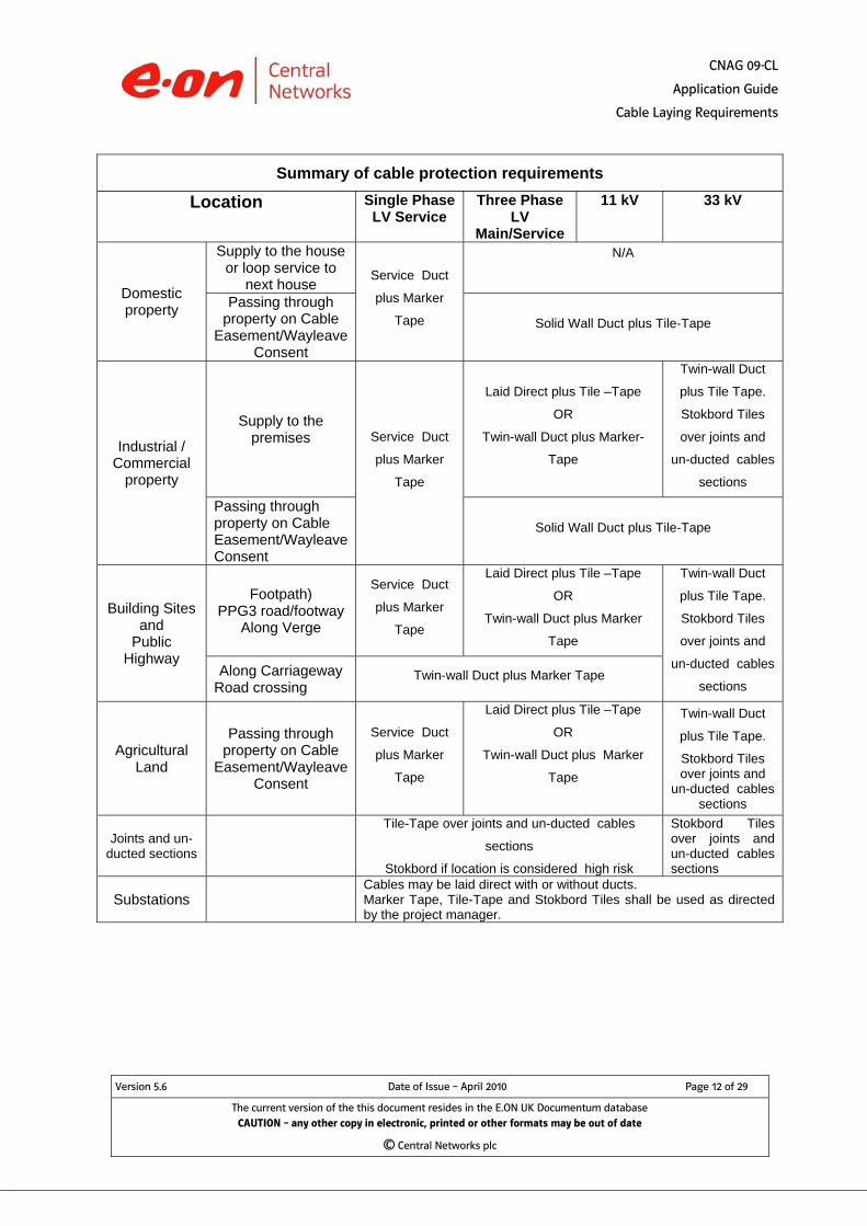
Summary of cable protection requirements
Location Single Phase LV Service
Three Phase LV
Main/Service
11 kV 33 kV
Domestic property
Supply to the house or loop service to
next house Service Duct
plus Marker
Tape
N/A
Passing through property on Cable
Easement/Wayleave Consent
Solid Wall Duct plus Tile-Tape
Industrial / Commercial
property
Supply to the premises Service Duct
plus Marker
Tape
Laid Direct plus Tile –Tape
OR
Twin-wall Duct plus Marker-
Tape
Twin-wall Duct
plus Tile Tape.
Stokbord Tiles
over joints and
un-ducted cables
sections
Passing through property on Cable Easement/Wayleave Consent
Solid Wall Duct plus Tile-Tape
Building Sites and
Public Highway
Footpath) PPG3 road/footway
Along Verge
Service Duct
plus Marker
Tape
Laid Direct plus Tile –Tape
OR
Twin-wall Duct plus Marker
Tape
Twin-wall Duct
plus Tile Tape.
Stokbord Tiles
over joints and
un-ducted cables
sections Along Carriageway
Road crossing Twin-wall Duct plus Marker Tape
Agricultural Land
Passing through property on Cable
Easement/Wayleave Consent
Service Duct
plus Marker
Tape
Laid Direct plus Tile –Tape
OR
Twin-wall Duct plus Marker
Tape
Twin-wall Duct
plus Tile Tape.
Stokbord Tiles over joints and
un-ducted cables sections
Joints and un- ducted sections
Tile-Tape over joints and un-ducted cables
sections
Stokbord if location is considered high risk
Stokbord Tiles over joints and un-ducted cables sections
Substations Cables may be laid direct with or without ducts. Marker Tape, Tile-Tape and Stokbord Tiles shall be used as directed by the project manager.
CNAG 09-CL
Application Guide
Cable Laying Requirements
Version 5.6 Date of Issue – April 2010 Page 13 of 29
The current version of the this document resides in the E.ON UK Documentum database CAUTION – any other copy in electronic, printed or other formats may be out of date
© Central Networks plc
3.2.2 Blinding with fines
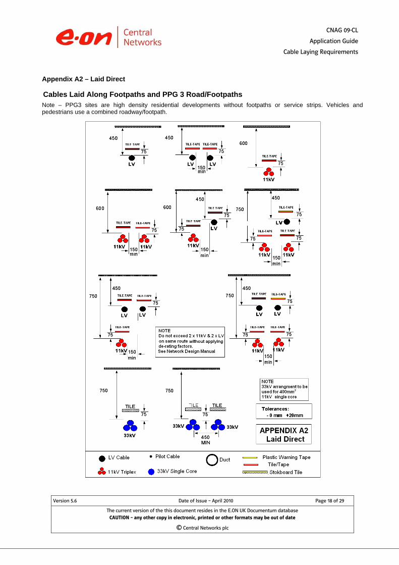
Laid direct cable - the trench bottom shall be cleared of all sharp objects before pulling in the cable. The Cable Installer shall place a 25mm layer of blinding material on the trench bottom before pulling in. The installed cable shall be covered with a layer of blinding material which shall cover the cable to a depth of 75 mm. Ducts – shall be consolidated into the blinding material ensuring that no voids exist under or between ducts. The LV & 11kV duct arrangements show a spacing of 25mm between ducts to enable the voids between ducts to be filled and consolidated with fine-fill. The 33kV trefoil arrangement shows the three ducts touching. These ducts shall be fastened together with suitable plastic cable ties or clips to prevent movement and be treated as a single duct for backfilling purposes. This is to ensure that the three single cores remain in trefoil formation at a controlled spacing which has been taken into account in the cable rating calculations. (Note if the cores are separated too far the circulating currents in the screen wires increase and cause additional heating). LV and 11kv direct laid cables shall be blinded with a fine-fill material consisting of:
• Excavated earth or soil which contains no stones or flints. • Imported excavated materials that have been screened through a 3
mm diameter mesh. or • Cable laying sand, i.e. stone free sand of a composition suitable for
cable laying and which will resist migration. (Builders sand is expressly prohibited).
33kV direct laid cable shall be blinded with cable laying sand or other fine material as may be agreed with the Project Manager. Ducts at all voltages shall be blinded with a fine-fill material consisting of:
• Excavated earth or soil which contains no stones or flints. • Imported excavated materials that have been screened through a 3
mm diameter mesh.
3.2.3 Ducts across or along roads. Ducts installed by open cut methods shall have the marker tape laid at a position below the road base construction directly above the ducts. At road crossings the ends of the ducts shall extend 150mm into the footpath as measured from the footpath edge of the kerb.
3.2.4 Direction of road crossings.
CNAG 09-CL
Application Guide
Cable Laying Requirements
Version 5.6 Date of Issue – April 2010 Page 14 of 29
The current version of the this document resides in the E.ON UK Documentum database CAUTION – any other copy in electronic, printed or other formats may be out of date
© Central Networks plc
When installing road crossing ducts the Cable Installer should be aware of the bending radii and pulling tensions of the cable concerned. The Project Manager shall normally accept proposals to install a crossing at a slight diagonal across the road to ease bending and friction where necessary.
3.2.5 Ducts installed by trenchless methods. Ducts for HV cables shall be supplied by the Cable Installer which shall be mechanically suitable for the installation method to be used. The ducts shall be coloured black or red and be embossed with the legend “Danger Electric Cable” in such a way that the marking shall not be damaged during the pulling in process.
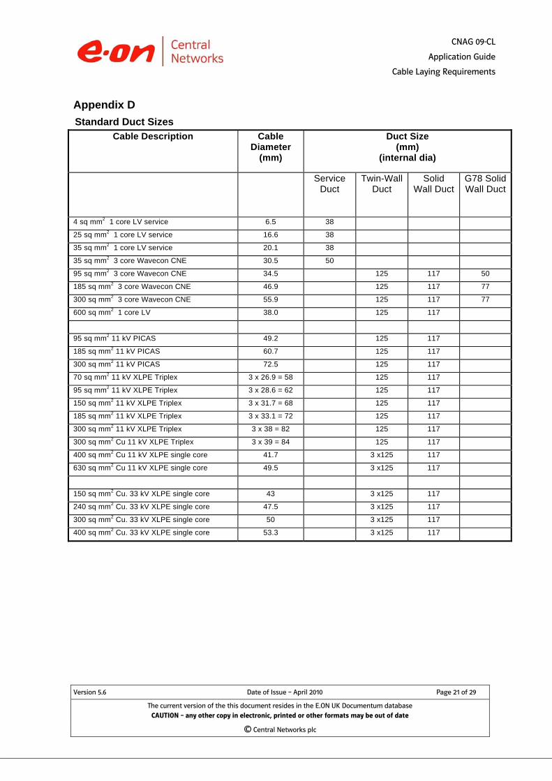
3.2.6 The ducts sizes. Appendix D shows the size of duct required for each cable size.
3.3 Pulling in cables
3.3.1 Bending radii. The minimum bending radii of cables currently used by Central Networks are shown in appendix E. Where cable types not shown in appendix E are to be installed the Project Manager shall give guidance to the Cable Installer.
3.3.2 Pulling in tensions. The maximum pulling in tensions are shown in appendix F. Any winch used shall have a dynamometer fitted which shall be calibrated at the intervals shown in the Cable Installer’s method statement.
3.3.3 Manhandling. Where cables are to be manhandled, flaked or pulled in from moving vehicles the Cable Installer shall show how this is to be done in his method statement. In the case of flaking, the bending radii must not be less than twice the minimum shown in appendix E.
3.3.4 Sealing cut ends. Cables shall be sealed by means of a mastic lined heat shrink cable cap or cold shrink cap. Single core cables laid up in triplex formation shall have a separate cap applied to each core. The Cable Installer’s method statement shall detail the method of application which shall include the degreasing and abrading the cable sheaths.
3.3.5 Precautions during low temperatures.
PVC SHEATHED CABLES

CNAG 09-CL
Application Guide
Cable Laying Requirements
Where the ambient temperature of the Site is below zero degrees centigrade, precautions are necessary to prevent the PVC cable sheath from cracking. The Cable Installer shall arrange for any drums to be used during sub zero conditions to be maintained above zero degrees centigrade for 24 hours before pulling in takes place. The Cable Installer’s method statement shall show the proposed method of pre-warming cables that have to be laid at short notice or in an emergency. The following cables are PVC sheathed:
Hybrid Service Cable LV CNE Cable (Alpex & Wavecon) 11kV PICAS Cable
POLYETHYLENE SHEATHED CABLES
Polyethylene (MDPE) sheathed cables can be laid at temperatures down to 20O C below zero. The following cables are Polyethylene sheathed:
11 kV XPLE Triplex 33 kV XPLE Single Core
3.3.6 Single core cables. Single core cables shall be arranged in trefoil formation and bound with plastic cable ties every 1.2 metres. Where cables are supplied already bundled in triplex formation cable ties will not be required.
4. Earthing and Bonding of Single Core Cables 4.1 LV Cables
LV cables shall be earthed and bonded in accordance with the Earthing Manual - Section E6 - Protective Multiple Earthing.
4.2 Three Core Cables There are no special requirements for earthing and bonding three core cables.
4.3 Single Core Cables
11kV Triplex Cables. Triplex to triplex joints. The screens of each core shall be jointed through without bonding to the other phases. Triplex to PICAS or PILSWA joints. The screens of each core shall be jointed to
Version 5.6 Date of Issue – April 2010 Page 15 of 29
The current version of the this document resides in the E.ON UK Documentum database CAUTION – any other copy in electronic, printed or other formats may be out of date
© Central Networks plc
Not sure if it’s PVC or Polyethylene? Simple Test: Cut off a piece of sheath and place it in water. PVC sinks Polyethylene floats (so does XLPE)

CNAG 09-CL
Application Guide
Cable Laying Requirements
Version 5.6 Date of Issue – April 2010 Page 16 of 29
The current version of the this document resides in the E.ON UK Documentum database CAUTION – any other copy in electronic, printed or other formats may be out of date
© Central Networks plc
the cable sheath. At terminations the screens from all three cores shall be connected together and connected to the HV earth (i.e. Solid Bonding).
Transformer Singles (11kV/33kV, Primary/Grid S/S).
These may be laid in trefoil or flat formation.
In either case the screens shall be earthed at one end only to prevent de-rating due to circulating currents (i.e. Single Point Bonding).
33kV Circuits
Circuits up to 10km long may be laid in trefoil (direct or in ducts) and shall be earthed at both ends. (Solid Bonding).
Circuits laid in trefoil over 10km long and all circuits laid in flat formation (of any length) may be subject to de-rating due to screen wire circulating currents and/or excessive screen voltage. Please refer to the Cables Specialist in Network Standards for guidance on Cross-Bonding the screens.

CNAG 09-CL
Application Guide
Cable Laying Requirements
Version 5.6 Date of Issue – April 2010 Page 17 of 29
The current version of the this document resides in the E.ON UK Documentum database CAUTION – any other copy in electronic, printed or other formats may be out of date
© Central Networks plc
Appendix A1 - Ducted
Cables Laid Along Footpaths and PPG 3 Road/Footpaths Note – PPG3 sites are high density residential developments without footpaths or service strips. Vehicles and pedestrians use a combined roadway/footpath.
CNAG 09-CL
Application Guide
Cable Laying Requirements
Appendix A2 – Laid Direct
Cables Laid Along Footpaths and PPG 3 Road/Footpaths Note – PPG3 sites are high density residential developments without footpaths or service strips. Vehicles and pedestrians use a combined roadway/footpath.
Version 5.6 Date of Issue – April 2010 Page 18 of 29
The current version of the this document resides in the E.ON UK Documentum database CAUTION – any other copy in electronic, printed or other formats may be out of date
© Central Networks plc

CNAG 09-CL
Application Guide
Cable Laying Requirements
Version 5.6 Date of Issue – April 2010 Page 19 of 29
The current version of the this document resides in the E.ON UK Documentum database CAUTION – any other copy in electronic, printed or other formats may be out of date
© Central Networks plc
Appendix B Cable Laid in Agricultural Land

CNAG 09-CL
Application Guide
Cable Laying Requirements
Version 5.6 Date of Issue – April 2010 Page 20 of 29
The current version of the this document resides in the E.ON UK Documentum database CAUTION – any other copy in electronic, printed or other formats may be out of date
© Central Networks plc
Appendix C Cables Laid Across and Along Roads Note – Does not apply to PPG 3 sites in high density residential developments. See Appendix A
CNAG 09-CL
Application Guide
Cable Laying Requirements
Version 5.6 Date of Issue – April 2010 Page 21 of 29
The current version of the this document resides in the E.ON UK Documentum database CAUTION – any other copy in electronic, printed or other formats may be out of date
© Central Networks plc
Appendix D Standard Duct Sizes
Cable Description Cable Diameter
(mm)
Duct Size (mm)
(internal dia)
Service Duct
Twin-Wall Duct
Solid Wall Duct
G78 Solid Wall Duct
4 sq mm2 1 core LV service 6.5 38
25 sq mm2 1 core LV service 16.6 38
35 sq mm2 1 core LV service 20.1 38
35 sq mm2 3 core Wavecon CNE 30.5 50
95 sq mm2 3 core Wavecon CNE 34.5 125 117 50
185 sq mm2 3 core Wavecon CNE 46.9 125 117 77
300 sq mm2 3 core Wavecon CNE 55.9 125 117 77
600 sq mm2 1 core LV 38.0 125 117
95 sq mm2 11 kV PICAS 49.2 125 117
185 sq mm2 11 kV PICAS 60.7 125 117
300 sq mm2 11 kV PICAS 72.5 125 117
70 sq mm2 11 kV XLPE Triplex 3 x 26.9 = 58 125 117
95 sq mm2 11 kV XLPE Triplex 3 x 28.6 = 62 125 117
150 sq mm2 11 kV XLPE Triplex 3 x 31.7 = 68 125 117
185 sq mm2 11 kV XLPE Triplex 3 x 33.1 = 72 125 117
300 sq mm2 11 kV XLPE Triplex 3 x 38 = 82 125 117
300 sq mm2 Cu 11 kV XLPE Triplex 3 x 39 = 84 125 117
400 sq mm2 Cu 11 kV XLPE single core 41.7 3 x125 117
630 sq mm2 Cu 11 kV XLPE single core 49.5 3 x125 117
150 sq mm2 Cu. 33 kV XLPE single core 43 3 x125 117
240 sq mm2 Cu. 33 kV XLPE single core 47.5 3 x125 117
300 sq mm2 Cu. 33 kV XLPE single core 50 3 x125 117
400 sq mm2 Cu. 33 kV XLPE single core 53.3 3 x125 117

CNAG 09-CL
Application Guide
Cable Laying Requirements
Version 5.6 Date of Issue – April 2010 Page 22 of 29
The current version of the this document resides in the E.ON UK Documentum database CAUTION – any other copy in electronic, printed or other formats may be out of date
© Central Networks plc
Appendix E
Minimum Bending Radii
Cable Description Minimum radius of bend
on route (Metres)
at termination (Metres)
4 sq mm2 1 core LV service 0.075 0.075
25 sq mm2 1 core LV service 0.10 0.10
35 sq mm2 1 core LV service 0.13 0.13
35 sq mm2 3 core Wavecon CNE 0.45 0.45
95 sq mm2 3 core Wavecon CNE 0.65 0.40
185 sq mm2 3 core Wavecon CNE 0.85 0.54
300 sq mm2 3 core Wavecon CNE 0.95 0.620
600 sq mm2 1 core LV 0.85 0.85
95 sq mm2 11 kV PICAS 0.60 0.58
185 sq mm2 11 kV PICAS 0.75 0.60
300 sq mm2 11 kV PICAS 0.90 0.70
70 sq mm2 11 kV XLPE Triplex 0.55 0.425
95 sq mm2 11 kV XLPE Triplex 0.575 0.45
150 sq mm2 11 kV XLPE Triplex 0.65 0.50
185 sq mm2 11 kV XLPE Triplex 0.70 0.55
300 sq mm2 11 kV XLPE Triplex 0.80 0.60
150 sq mm2 Cu. 33kV 1 core XLPE (3 in trefoil) 0.90 0.65
240 sq mm2 Cu. 33kV 1 core XLPE (3 in trefoil) 0.95 0.75
300 sq mm2 Cu. 33kV 1 core XLPE (3 in trefoil) 1.00 0.75
400 sq mm2 Cu. 33kV 1 core XLPE (3 in trefoil) 1.10 0.80
CNAG 09-CL
Application Guide
Cable Laying Requirements
Version 5.6 Date of Issue – April 2010 Page 23 of 29
The current version of the this document resides in the E.ON UK Documentum database CAUTION – any other copy in electronic, printed or other formats may be out of date
© Central Networks plc
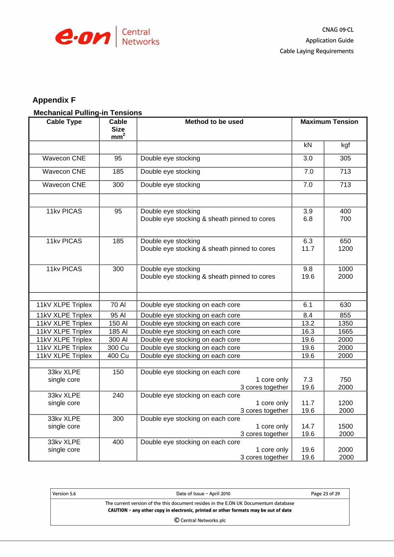
Appendix F Mechanical Pulling-in Tensions
Cable Type Cable Size mm2
Method to be used Maximum Tension
kN kgf
Wavecon CNE 95 Double eye stocking 3.0 305
Wavecon CNE 185 Double eye stocking 7.0 713
Wavecon CNE 300 Double eye stocking 7.0 713
11kv PICAS 95 Double eye stocking Double eye stocking & sheath pinned to cores
3.9 6.8
400 700
11kv PICAS 185 Double eye stocking Double eye stocking & sheath pinned to cores
6.3 11.7
650 1200
11kv PICAS 300 Double eye stocking Double eye stocking & sheath pinned to cores
9.8 19.6
1000 2000
11kV XLPE Triplex 70 Al Double eye stocking on each core 6.1 630 11kV XLPE Triplex 95 Al Double eye stocking on each core 8.4 855 11kV XLPE Triplex 150 Al Double eye stocking on each core 13.2 1350 11kV XLPE Triplex 185 Al Double eye stocking on each core 16.3 1665 11kV XLPE Triplex 300 Al Double eye stocking on each core 19.6 2000 11kV XLPE Triplex 300 Cu Double eye stocking on each core 19.6 2000 11kV XLPE Triplex 400 Cu Double eye stocking on each core 19.6 2000
33kv XLPE single core
150 Double eye stocking on each core 1 core only
3 cores together
7.3 19.6
750 2000
33kv XLPE single core
240 Double eye stocking on each core 1 core only
3 cores together
11.7 19.6
1200 2000
33kv XLPE single core
300 Double eye stocking on each core 1 core only
3 cores together
14.7 19.6
1500 2000
33kv XLPE single core
400 Double eye stocking on each core 1 core only
3 cores together
19.6 19.6
2000 2000
CNAG 09-CL
Application Guide
Cable Laying Requirements
Version 5.6 Date of Issue – April 2010 Page 24 of 29
The current version of the this document resides in the E.ON UK Documentum database CAUTION – any other copy in electronic, printed or other formats may be out of date
© Central Networks plc
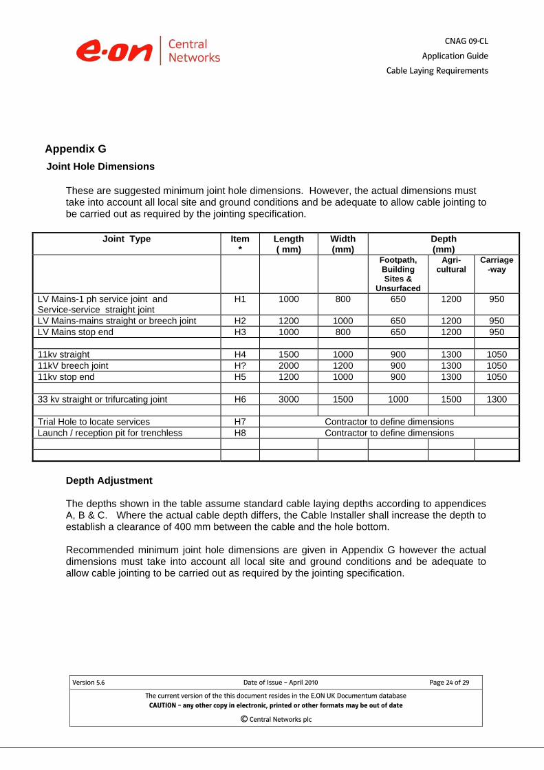
Appendix G Joint Hole Dimensions
These are suggested minimum joint hole dimensions. However, the actual dimensions must take into account all local site and ground conditions and be adequate to allow cable jointing to be carried out as required by the jointing specification.
Joint Type Item *
Length ( mm)
Width (mm)
Depth (mm)
Footpath, Building Sites &
Unsurfaced
Agri-cultural
Carriage-way
LV Mains-1 ph service joint and Service-service straight joint
H1 1000 800 650 1200 950
LV Mains-mains straight or breech joint H2 1200 1000 650 1200 950 LV Mains stop end H3 1000 800 650 1200 950 11kv straight H4 1500 1000 900 1300 1050 11kV breech joint H? 2000 1200 900 1300 1050 11kv stop end H5 1200 1000 900 1300 1050 33 kv straight or trifurcating joint H6 3000 1500 1000 1500 1300 Trial Hole to locate services H7 Contractor to define dimensions Launch / reception pit for trenchless H8 Contractor to define dimensions
Depth Adjustment The depths shown in the table assume standard cable laying depths according to appendices A, B & C. Where the actual cable depth differs, the Cable Installer shall increase the depth to establish a clearance of 400 mm between the cable and the hole bottom. Recommended minimum joint hole dimensions are given in Appendix G however the actual dimensions must take into account all local site and ground conditions and be adequate to allow cable jointing to be carried out as required by the jointing specification.
CNAG 09-CL
Application Guide
Cable Laying Requirements
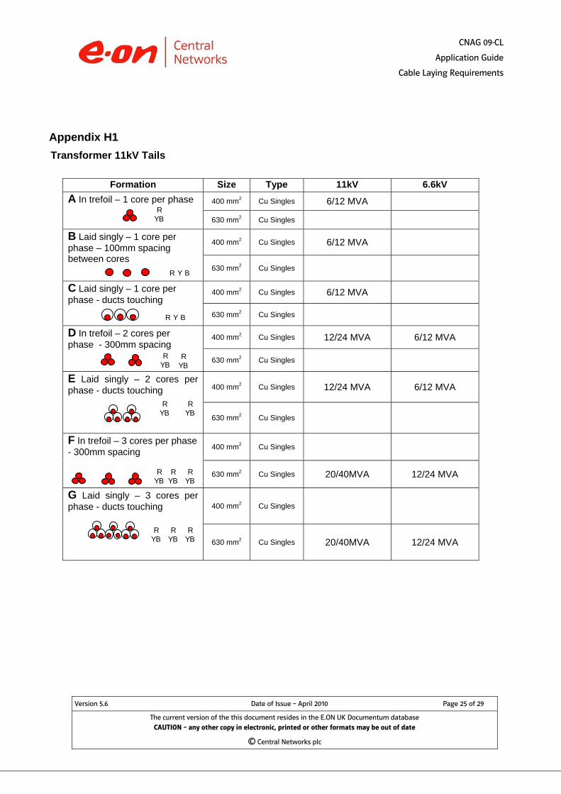
Appendix H1 Transformer 11kV Tails
Formation Size Type 11kV 6.6kV
A In trefoil – 1 core per phase 400 mm2 Cu Singles 6/12 MVA
630 mm2 Cu Singles
B Laid singly – 1 core per phase – 100mm spacing between cores
400 mm2 Cu Singles 6/12 MVA
630 mm2 Cu Singles
C Laid singly – 1 core per phase - ducts touching
400 mm2 Cu Singles 6/12 MVA
630 mm2 Cu Singles
D In trefoil – 2 cores per phase - 300mm spacing
400 mm2 Cu Singles 12/24 MVA 6/12 MVA
630 mm2 Cu Singles
E Laid singly – 2 cores per phase - ducts touching 400 mm2 Cu Singles 12/24 MVA 6/12 MVA
630 mm2 Cu Singles
F In trefoil – 3 cores per phase - 300mm spacing
400 mm2 Cu Singles
630 mm2 Cu Singles 20/40MVA 12/24 MVA
G Laid singly – 3 cores per phase - ducts touching 400 mm2 Cu Singles
630 mm2 Cu Singles 20/40MVA 12/24 MVA
R YB
R Y B
R Y B
R YB
R YB
R YB
R YB
R YB
R YB
R YB
Version 5.6 Date of Issue – April 2010 Page 25 of 29
The current version of the this document resides in the E.ON UK Documentum database CAUTION – any other copy in electronic, printed or other formats may be out of date
© Central Networks plc
R YB
R YB
R YB

CNAG 09-CL
Application Guide
Cable Laying Requirements
Appendix H2 Transformer 33kV Tails
Formation Size Type HV Tails of
33/11kV Transformer
LV Tails of 132/33kV
Transformer A In trefoil – 1 core per phase 150 mm2 Cu Singles 4/8, 6/12, 12/24
MVA
400 mm2 Cu Singles 20/40 MVA
B Laid singly – 1 core per phase – 100mm spacing between cores
150 mm2 Cu Singles 4/8, 6/12, 12/24 MVA
400 mm2 Cu Singles 20/40 MVA
C Laid singly – 1 core per phase - ducts touching
150 mm2 Cu Singles 4/8, 6/12, 12/24 MVA
400 mm2 Cu Singles 20/40 MVA
D In trefoil – 2 cores per phase - 300mm spacing 500 mm2 Cu Singles 30/60/78 MVA
E Laid singly – 2 cores per phase - ducts touching
500 mm2 Cu Singles 30/60/78 MVA
F In trefoil – 3 cores per phase - 300mm spacing 500 mm2 Cu Singles 45/90/117 MVA
G Laid singly – 3 cores per phase - ducts touching
500 mm2 Cu Singles 45/90/117 MVA
R YB
R Y B
R Y B
R YB
R YB
R YB
R YB
R YB
R YB
R YB
Version 5.6 Date of Issue – April 2010 Page 26 of 29
The current version of the this document resides in the E.ON UK Documentum database CAUTION – any other copy in electronic, printed or other formats may be out of date
© Central Networks plc
R YB
R YB
R YB
CNAG 09-CL
Application Guide
Cable Laying Requirements
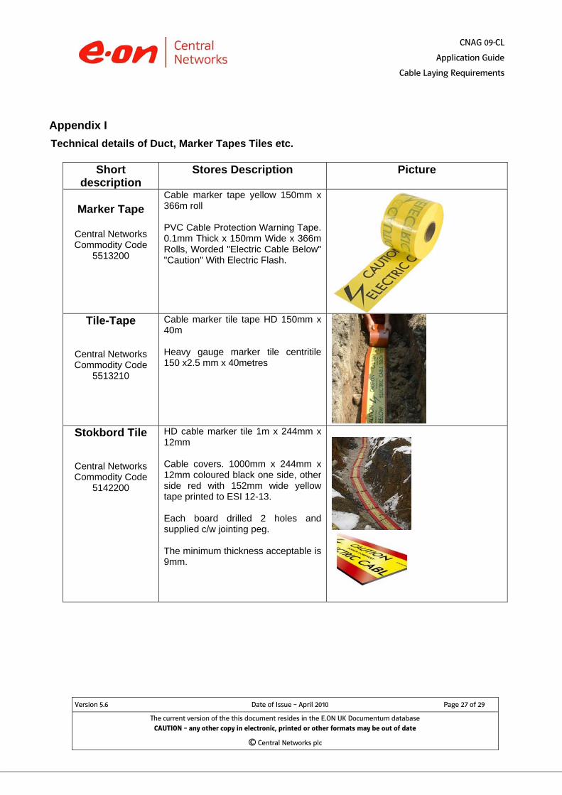
Appendix I Technical details of Duct, Marker Tapes Tiles etc.
Short
description Stores Description Picture
Marker Tape
Central Networks Commodity Code
5513200
Cable marker tape yellow 150mm x 366m roll PVC Cable Protection Warning Tape. 0.1mm Thick x 150mm Wide x 366m Rolls, Worded "Electric Cable Below" "Caution" With Electric Flash.
Tile-Tape
Central Networks Commodity Code
5513210
Cable marker tile tape HD 150mm x 40m Heavy gauge marker tile centritile 150 x2.5 mm x 40metres
Stokbord Tile
Central Networks Commodity Code
5142200
HD cable marker tile 1m x 244mm x 12mm Cable covers. 1000mm x 244mm x 12mm coloured black one side, other side red with 152mm wide yellow tape printed to ESI 12-13. Each board drilled 2 holes and supplied c/w jointing peg. The minimum thickness acceptable is 9mm.
Version 5.6 Date of Issue – April 2010 Page 27 of 29
The current version of the this document resides in the E.ON UK Documentum database CAUTION – any other copy in electronic, printed or other formats may be out of date
© Central Networks plc

CNAG 09-CL
Application Guide
Cable Laying Requirements
Short
description Stores Description Picture
Service Duct Single Phase
Central Networks Commodity Code
5516385
Polyduct 32mm x 100m coil black (2.5mm) polyduct electric all single
phase service cables
EN 50086 2-4 compression strength 450N @23OC
(Class 3 to ENATS 12-24)
Service Ducts Three Phase
Central Networks Commodity Code
5516415
Polyduct 50mm x 50m coil black for
all 35mm three phase service
EN 50086 2-4 compression strength 450N @23OC
(Class 3 to ENATS 12-24)
Twin-Wall Duct
Central Networks Commodity Code
5341450
Duct 125mm x 3m rigiduct all HV & LV 125mm x 3m black rigiduct twin wall all mains cable LV HV to ENATS12-24 EN 50086 2-4 compression strength
450N @ 50OC (Class 2 to ENATS 12-24)
Solid Wall Duct (Coil)
Central Networks Commodity Code
4713570
uPVC Duct OD 125mm ID 117mm 50m coil EN 50086 2-4 compression strength
750 N @ 75OC (Class 1 to ENATS 12-24)
Solid Wall Duct (3m lengths)
Central Networks Commodity Code
TBA
uPVC Duct OD 125mm ID 117mm 3m length EN 50086 2-4 compression strength
750 N @ 75OC (Class 1 to ENATS 12-24)
NOTE – 3m straight lengths are to be placed on stock. Code to be advised
Version 5.6 Date of Issue – April 2010 Page 28 of 29
The current version of the this document resides in the E.ON UK Documentum database CAUTION – any other copy in electronic, printed or other formats may be out of date
© Central Networks plc
CNAG 09-CL
Application Guide
Cable Laying Requirements
Version 5.6 Date of Issue – April 2010 Page 29 of 29
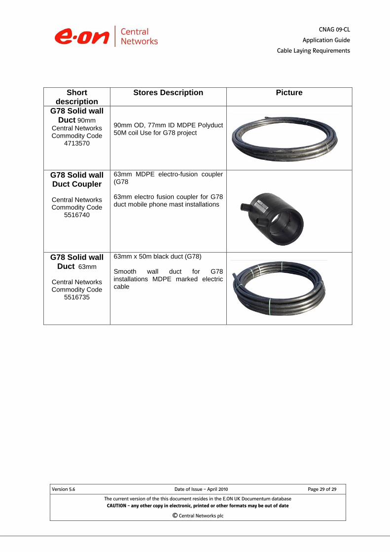
Short description
Stores Description Picture
G78 Solid wall Duct 90mm
Central Networks Commodity Code
4713570
90mm OD, 77mm ID MDPE Polyduct 50M coil Use for G78 project
G78 Solid wall Duct Coupler
Central Networks Commodity Code
5516740
63mm MDPE electro-fusion coupler (G78 63mm electro fusion coupler for G78 duct mobile phone mast installations
G78 Solid wall
Duct 63mm
Central Networks Commodity Code
5516735
63mm x 50m black duct (G78) Smooth wall duct for G78 installations MDPE marked electric cable
The current version of the this document resides in the E.ON UK Documentum database CAUTION – any other copy in electronic, printed or other formats may be out of date
© Central Networks plc