c200h-cp114 cam positioner unit - omron
TRANSCRIPT
C200H-CP114Cam Positioner UnitOperation ManualRevised January 2001
v
Notice:OMRON products are manufactured for use according to proper procedures by a qualified operatorand only for the purposes described in this manual.
The following conventions are used to indicate and classify precautions in this manual. Always heedthe information provided with them. Failure to heed precautions can result in injury to people or dam-age to property.
!DANGER Indicates an imminently hazardous situation which, if not avoided, will result in death orserious injury.
!WARNING Indicates a potentially hazardous situation which, if not avoided, could result in death orserious injury.
!Caution Indicates a potentially hazardous situation which, if not avoided, may result in minor ormoderate injury, or property damage.
OMRON Product ReferencesAll OMRON products are capitalized in this manual. The word “Unit” is also capitalized when it refers toan OMRON product, regardless of whether or not it appears in the proper name of the product.
The abbreviation “Ch,” which appears in some displays and on some OMRON products, often means“word” and is abbreviated “Wd” in documentation in this sense.
The abbreviation “PC” means Programmable Controller and is not used as an abbreviation for any-thing else.
Visual AidsThe following headings appear in the left column of the manual to help you locate different types ofinformation.
Note Indicates information of particular interest for efficient and convenient opera-tion of the product.
Reference Indicates supplementary information on related topics that may be of interestto the user.
1,2,3... 1. Indicates lists of one sort or another, such as procedures, checklists, etc.
OMRON, 1993All rights reserved. No part of this publication may be reproduced, stored in a retrieval system, or transmitted, in any form, orby any means, mechanical, electronic, photocopying, recording, or otherwise, without the prior written permission ofOMRON.
No patent liability is assumed with respect to the use of the information contained herein. Moreover, because OMRON is con-stantly striving to improve its high-quality products, the information contained in this manual is subject to change withoutnotice. Every precaution has been taken in the preparation of this manual. Nevertheless, OMRON assumes no responsibilityfor errors or omissions. Neither is any liability assumed for damages resulting from the use of the information contained inthis publication.
vii
TABLE OF CONTENTSPRECAUTIONS . . . . . . . . . . . . . . . . . . . . . . . . . . . . . . . . . . . xi
1 Intended Audience . . . . . . . . . . . . . . . . . . . . . . . . . . . . . . . . . . . . . . . . . . . . . . . . . . . . . . . . xii
2 General Precautions . . . . . . . . . . . . . . . . . . . . . . . . . . . . . . . . . . . . . . . . . . . . . . . . . . . . . . . xii
3 Safety Precautions. . . . . . . . . . . . . . . . . . . . . . . . . . . . . . . . . . . . . . . . . . . . . . . . . . . . . . . . . xii
4 Operating Environment Precautions . . . . . . . . . . . . . . . . . . . . . . . . . . . . . . . . . . . . . . . . . . . xii
5 Application Precautions . . . . . . . . . . . . . . . . . . . . . . . . . . . . . . . . . . . . . . . . . . . . . . . . . . . . xiii
SECTION 1Features and System Configuration . . . . . . . . . . . . . . . . . . . 1
1-1 Features . . . . . . . . . . . . . . . . . . . . . . . . . . . . . . . . . . . . . . . . . . . . . . . . . . . . . . . . . . . . . . . . 2
1-2 Basic System Configuration . . . . . . . . . . . . . . . . . . . . . . . . . . . . . . . . . . . . . . . . . . . . . . . . . 3
SECTION 2Connection and Settings. . . . . . . . . . . . . . . . . . . . . . . . . . . . . 5
2-1 Nomenclature and Functions . . . . . . . . . . . . . . . . . . . . . . . . . . . . . . . . . . . . . . . . . . . . . . . . 6
2-2 Switch Settings . . . . . . . . . . . . . . . . . . . . . . . . . . . . . . . . . . . . . . . . . . . . . . . . . . . . . . . . . . . 7
2-3 Wiring . . . . . . . . . . . . . . . . . . . . . . . . . . . . . . . . . . . . . . . . . . . . . . . . . . . . . . . . . . . . . . . . . . 8
SECTION 3Data Setting Console Operation . . . . . . . . . . . . . . . . . . . . . . 13
3-1 Operating Procedure . . . . . . . . . . . . . . . . . . . . . . . . . . . . . . . . . . . . . . . . . . . . . . . . . . . . . . . 14
3-2 Nomenclature and Functions . . . . . . . . . . . . . . . . . . . . . . . . . . . . . . . . . . . . . . . . . . . . . . . . 15
3-3 Data Setting and Monitoring. . . . . . . . . . . . . . . . . . . . . . . . . . . . . . . . . . . . . . . . . . . . . . . . . 17
SECTION 4PC Memory Allocation and Programming . . . . . . . . . . . . . 25
4-1 Memory Allocation . . . . . . . . . . . . . . . . . . . . . . . . . . . . . . . . . . . . . . . . . . . . . . . . . . . . . . . . 26
4-2 Peripheral Device Operations and Data Setting . . . . . . . . . . . . . . . . . . . . . . . . . . . . . . . . . . 32
4-3 Program Examples . . . . . . . . . . . . . . . . . . . . . . . . . . . . . . . . . . . . . . . . . . . . . . . . . . . . . . . . 37
SECTION 5Troubleshooting . . . . . . . . . . . . . . . . . . . . . . . . . . . . . . . . . . . 45
SECTION 5Error Detection . . . . . . . . . . . . . . . . . . . . . . . . . . . . . . . . . . . . . . . . . . . . . . . . . . . . . . 46
AppendicesA Specifications . . . . . . . . . . . . . . . . . . . . . . . . . . . . . . . . . . . . . . . . . . . . . . . . . . . . . . . . . . . . 49
B Resolvers . . . . . . . . . . . . . . . . . . . . . . . . . . . . . . . . . . . . . . . . . . . . . . . . . . . . . . . . . . . . . . . 51
C Dimensions . . . . . . . . . . . . . . . . . . . . . . . . . . . . . . . . . . . . . . . . . . . . . . . . . . . . . . . . . . . . . . 57
Index . . . . . . . . . . . . . . . . . . . . . . . . . . . . . . . . . . . . . . . . . . . . 59
Revision History . . . . . . . . . . . . . . . . . . . . . . . . . . . . . . . . . . . 61
ix
About this Manual:
This manual describes the installation and operation of the C200H-CP114 Cam Positioner Unit andincludes the sections described below. Also briefly described is the basic operation and installation ofthe C200H–DSC01 Data Setting Console.
Please read this manual carefully and be sure you understand the information provided beforeattempting to install and operate the Temperature Control Unit and Data Setting Console.
Section 1 provides Cam Positioner Unit features and describes its basic system configuration.
Section 2 provides information on the connections and settings of the Cam Positioner Unit.
Section 3 provides the basic operating procedures of the Data Setting Console including data settingsand monitoring.
Section 4 provides the C200H@ PC’s memory allocation for the Cam Positioner Unit. Basic program-ming procedures and examples are also provided.
Section 5 provides possible errors and corrections.
The Appendices provide information on specifications, resolvers, and dimensions.
!WARNING Failure to read and understand the information provided in this manual may result in per-sonal injury or death, damage to the product, or product failure. Please read each sectionin its entirety and be sure you understand the information provided in the section andrelated sections before attempting any of the procedures or operations given.
xi
PRECAUTIONS
This section provides general precautions for using the Programmable Controller (PC) and Cam Positioner Unit.
The information contained in this section is important for the safe and reliable application of the Cam PositionerUnit. You must read this section and understand the information contained before attempting to set up or operatea PC system and Cam Positioner Unit.
1 Intended Audience . . . . . . . . . . . . . . . . . . . . . . . . . . . . . . . . . . . . . . . . . . . . . xii2 General Precautions . . . . . . . . . . . . . . . . . . . . . . . . . . . . . . . . . . . . . . . . . . . . xii3 Safety Precautions. . . . . . . . . . . . . . . . . . . . . . . . . . . . . . . . . . . . . . . . . . . . . . xii4 Operating Environment Precautions . . . . . . . . . . . . . . . . . . . . . . . . . . . . . . . . xii5 Application Precautions . . . . . . . . . . . . . . . . . . . . . . . . . . . . . . . . . . . . . . . . . xiii

xii
Intended Audience 1
1 Intended AudienceThis manual is intended for the following personnel, who must also haveknowledge of electrical systems (an electrical engineer or the equivalent).
• Personnel in charge of installing FA systems
• Personnel in charge of designing FA systems
• Personnel in charge of managing FA systems and facilities
2 General PrecautionsThe user must operate the product according to the performance specifica-tions described in the operation manuals.
Before using the product under conditions which are not described in themanual or applying the product to nuclear control systems, railroad systems,aviation systems, vehicles, combustion systems, medical equipment, amuse-ment machines, safety equipment, and other systems, machines, and equip-ment that may have a serious influence on lives and property if usedimproperly, consult your OMRON representative.
Make sure that the ratings and performance characteristics of the product aresufficient for the systems, machines, and equipment, and be sure to providethe systems, machines, and equipment with double safety mechanisms.
This manual provides information for programming and operating the OMRONCam Positioner Unit. Be sure to read this manual before attempting to use thesoftware and keep this manual close at hand for reference during operation.
!WARNING It is extremely important that a PC and all PC Units be used for the specifiedpurpose and under the specified conditions, especially in applications that candirectly or indirectly affect human life. You must consult with your OMRONrepresentative before applying a PC System to the above-mentioned applica-tions.
3 Safety Precautions
!WARNING Do not attempt to take any Unit apart while power is being supplied. Doing somay result in electric shock.
!WARNING Do not touch any of the terminals or terminal blocks while power is being sup-plied. Doing so may result in electric shock.
4 Operating Environment Precautions
!Caution Do not operate the control system in the following places:
• Locations subject to direct sunlight.
• Locations subject to temperatures or humidity outside the range specifiedin the specifications.
• Locations subject to condensation as the result of severe changes in tem-perature.
• Locations subject to corrosive or flammable gases.
• Locations subject to dust (especially iron dust) or salts.
• Locations subject to exposure to water, oil, or chemicals.
xiii
Application Precautions 5
• Locations subject to shock or vibration.
!Caution Take appropriate and sufficient countermeasures when installing systems inthe following locations:
• Locations subject to static electricity or other forms of noise.
• Locations subject to strong electromagnetic fields.
• Locations subject to possible exposure to radioactivity.
• Locations close to power supplies.
!Caution The operating environment of the PC System can have a large effect on thelongevity and reliability of the system. Improper operating environments canlead to malfunction, failure, and other unforeseeable problems with the PCSystem. Be sure that the operating environment is within the specified condi-tions at installation and remains within the specified conditions during the lifeof the system.
5 Application PrecautionsObserve the following precautions when using the PC.
!WARNING Always heed these precautions. Failure to abide by the following precautionscould lead to serious or possibly fatal injury.
• Always connect to a ground of 100 Ω or less when installing the Units. Notconnecting to a ground of 100 Ω or less may result in electric shock.
• Always turn off the power supply to the PC before attempting any of thefollowing. Not turning off the power supply may result in malfunction orelectric shock.
• Mounting or dismounting I/O Units, Power Supply Units, CPU Units,Memory Cassettes, or any other Units.
• Assembling the Units.
• Setting DIP switch or rotary switches.
• Connecting or wiring the cables.
• Connecting or disconnecting the connectors.
!Caution Failure to abide by the following precautions could lead to faulty operation ofthe PC or the system, or could damage the PC or PC Units. Always heedthese precautions.
• Fail-safe measures must be taken by the customer to ensure safety in theevent of incorrect, missing, or abnormal signals caused by broken signallines, momentary power interruptions, or other causes.
• Interlock circuits, limit circuits, and similar safety measures in external cir-cuits (i.e., not in the Programmable Controller) must be provided by thecustomer.
• Always use the power supply voltage specified in this manual. An incor-rect voltage may result in malfunction or burning.
• Take appropriate measures to ensure that the specified power with therated voltage and frequency is supplied. Be particularly careful in placeswhere the power supply is unstable. An incorrect power supply may resultin malfunction.
xiv
Application Precautions 5
• Do not apply voltages to the Input Units in excess of the rated input volt-age. Excess voltages may result in burning.
• Do not apply voltages or connect loads to the Output Units in excess ofthe maximum switching capacity. Excess voltage or loads may result inburning.
• Install external breakers and take other safety measures against short-cir-cuiting in external wiring. Insufficient safety measures against short-cir-cuiting may result in burning.
• Disconnect the functional ground terminal when performing withstandvoltage tests. Not disconnecting the functional ground terminal may resultin burning.
• Do not attempt to disassemble, repair, or modify any Units.
• Be sure that all the mounting screws, terminal screws, and cable connec-tor screws are tightened to the torque specified in the relevant manuals.Incorrect tightening torque may result in malfunction.
• Leave the label attached to the Unit when wiring. Removing the label mayresult in malfunction if foreign matter such as wire cuttings enter the Unit.
• Remove the label after the completion of wiring to ensure proper heat dis-sipation. Leaving the label attached may result in malfunction.
• Use crimp terminals for wiring. Do not connect bare stranded wiresdirectly to terminals. Connection of bare stranded wires may result inburning.
• Double-check all the wiring before turning on the power supply. Incorrectwiring may result in burning.
• Wire all connections correctly.
• Mount the Unit only after checking the terminal block completely.
• Be sure that the terminal blocks, Memory Units, expansion cables, andother items with locking devices are properly locked into place. Improperlocking may result in malfunction.
• Check the user program for proper execution before actually running it onthe Unit. Not checking the program may result in an unexpected opera-tion.
• Confirm that no adverse effect will occur in the system before attemptingany of the following. Not doing so may result in an unexpected operation.
• Changing the operating mode of the PC.
• Force-setting/force-resetting any bit in memory.
• Changing the present value of any word or any set value in memory.
• Resume operation only after transferring to the new CPU Unit the con-tents of the DM Area, HR Area, and other data required for resumingoperation. Not doing so may result in an unexpected operation.
• Do not pull on the cables or bend the cables beyond their natural limit.Doing either of these may break the cables.
• Do not place objects on top of the cables or other wiring lines. Doing somay break the cables.
• Before touching the Unit, be sure to first touch a grounded metallic objectin order to discharge any static built-up. Not doing so may result in mal-function or damage.
• Install the Units properly as specified in the operation manuals. Improperinstallation of the Units may result in malfunction.

1
SECTION 1Features and System Configuration
This section provides Cam Positioner Unit features and describes its basic system configuration.
1-1 Features . . . . . . . . . . . . . . . . . . . . . . . . . . . . . . . . . . . . . . . . . . . . . . . . . . . . . . 2
1-2 Basic System Configuration . . . . . . . . . . . . . . . . . . . . . . . . . . . . . . . . . . . . . . 3
2
Features Section 1-1
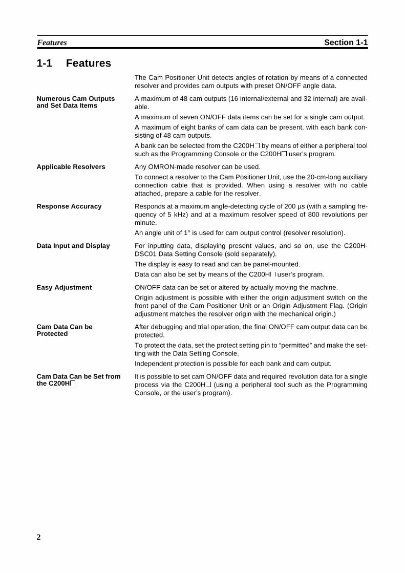
1-1 FeaturesThe Cam Positioner Unit detects angles of rotation by means of a connectedresolver and provides cam outputs with preset ON/OFF angle data.
Numerous Cam Outputsand Set Data Items
A maximum of 48 cam outputs (16 internal/external and 32 internal) are avail-able.
A maximum of seven ON/OFF data items can be set for a single cam output.
A maximum of eight banks of cam data can be present, with each bank con-sisting of 48 cam outputs.
A bank can be selected from the C200H@ by means of either a peripheral toolsuch as the Programming Console or the C200H@ user’s program.
Applicable Resolvers Any OMRON-made resolver can be used.
To connect a resolver to the Cam Positioner Unit, use the 20-cm-long auxiliaryconnection cable that is provided. When using a resolver with no cableattached, prepare a cable for the resolver.
Response Accuracy Responds at a maximum angle-detecting cycle of 200 µs (with a sampling fre-quency of 5 kHz) and at a maximum resolver speed of 800 revolutions perminute.
An angle unit of 1° is used for cam output control (resolver resolution).
Data Input and Display For inputting data, displaying present values, and so on, use the C200H-DSC01 Data Setting Console (sold separately).
The display is easy to read and can be panel-mounted.
Data can also be set by means of the C200H@ user’s program.
Easy Adjustment ON/OFF data can be set or altered by actually moving the machine.
Origin adjustment is possible with either the origin adjustment switch on thefront panel of the Cam Positioner Unit or an Origin Adjustment Flag. (Originadjustment matches the resolver origin with the mechanical origin.)
Cam Data Can beProtected
After debugging and trial operation, the final ON/OFF cam output data can beprotected.
To protect the data, set the protect setting pin to “permitted” and make the set-ting with the Data Setting Console.
Independent protection is possible for each bank and cam output.
Cam Data Can be Set fromthe C200H@
It is possible to set cam ON/OFF data and required revolution data for a singleprocess via the C200H@ (using a peripheral tool such as the ProgrammingConsole, or the user’s program).
3
Basic System Configuration Section 1-2
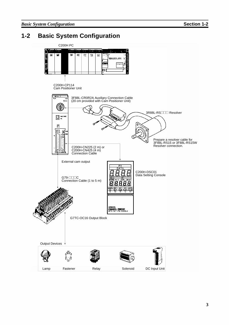
1-2 Basic System Configuration
C200H-CP114 Cam Positioner Unit
3F88L-CR0R2A Auxiliary Connection Cable (20 cm provided with Cam Positioner Unit)
3R88L-RS@@@ Resolver
C200H-CN225 (2 m) or C200H-CN425 (4 m) Connection Cable
External cam output
G79-@@@C Connection Cable (1 to 5 m)
Prepare a resolver cable for 3F88L-RS15 or 3F88L-RS15W Resolver connection.
C200H-DSC01 Data Setting Console
G7TC-OC16 Output Block
Output Devices
Lamp Fastener Relay Solenoid DC Input Unit
C200H PC
4
Basic System Configuration Section 1-2
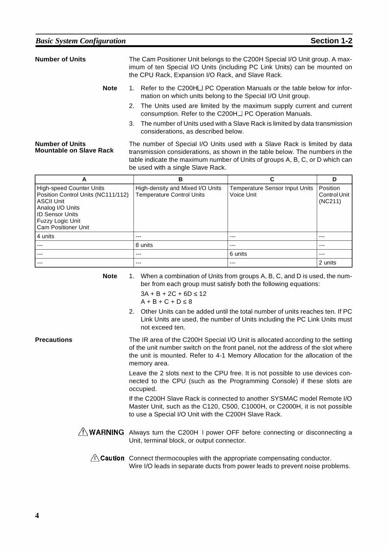
Number of Units The Cam Positioner Unit belongs to the C200H Special I/O Unit group. A max-imum of ten Special I/O Units (including PC Link Units) can be mounted onthe CPU Rack, Expansion I/O Rack, and Slave Rack.
Note 1. Refer to the C200H@ PC Operation Manuals or the table below for infor-mation on which units belong to the Special I/O Unit group.
2. The Units used are limited by the maximum supply current and currentconsumption. Refer to the C200H@ PC Operation Manuals.
3. The number of Units used with a Slave Rack is limited by data transmissionconsiderations, as described below.
Number of UnitsMountable on Slave Rack
The number of Special I/O Units used with a Slave Rack is limited by datatransmission considerations, as shown in the table below. The numbers in thetable indicate the maximum number of Units of groups A, B, C, or D which canbe used with a single Slave Rack.
Note 1. When a combination of Units from groups A, B, C, and D is used, the num-ber from each group must satisfy both the following equations:
3A + B + 2C + 6D ≤ 12A + B + C + D ≤ 8
2. Other Units can be added until the total number of units reaches ten. If PCLink Units are used, the number of Units including the PC Link Units mustnot exceed ten.
Precautions The IR area of the C200H Special I/O Unit is allocated according to the settingof the unit number switch on the front panel, not the address of the slot wherethe unit is mounted. Refer to 4-1 Memory Allocation for the allocation of thememory area.
Leave the 2 slots next to the CPU free. It is not possible to use devices con-nected to the CPU (such as the Programming Console) if these slots areoccupied.
If the C200H Slave Rack is connected to another SYSMAC model Remote I/OMaster Unit, such as the C120, C500, C1000H, or C2000H, it is not possibleto use a Special I/O Unit with the C200H Slave Rack.
!WARNING Always turn the C200H@ power OFF before connecting or disconnecting aUnit, terminal block, or output connector.
!Caution Connect thermocouples with the appropriate compensating conductor.Wire I/O leads in separate ducts from power leads to prevent noise problems.
A B C D
High-speed Counter UnitsPosition Control Units (NC111/112)ASCII UnitAnalog I/O UnitsID Sensor UnitsFuzzy Logic UnitCam Positioner Unit
High-density and Mixed I/O UnitsTemperature Control Units
Temperature Sensor Input UnitsVoice Unit
PositionControl Unit(NC211)
4 units --- --- ---
--- 8 units --- ---
--- --- 6 units ---
--- --- --- 2 units
5
SECTION 2Connection and Settings
This section provides information on the connections and settings of the Cam Positioner Unit.
2-1 Nomenclature and Functions . . . . . . . . . . . . . . . . . . . . . . . . . . . . . . . . . . . . . 6
2-2 Switch Settings . . . . . . . . . . . . . . . . . . . . . . . . . . . . . . . . . . . . . . . . . . . . . . . . 7
2-3 Wiring . . . . . . . . . . . . . . . . . . . . . . . . . . . . . . . . . . . . . . . . . . . . . . . . . . . . . . . 8
2-3-1 External Cam Output . . . . . . . . . . . . . . . . . . . . . . . . . . . . . . . . . . . . 8
2-3-2 Resolver Connection Cable . . . . . . . . . . . . . . . . . . . . . . . . . . . . . . . 11
2-3-3 Data Setting Console Cables . . . . . . . . . . . . . . . . . . . . . . . . . . . . . . 12
6
Nomenclature and Functions Section 2-1
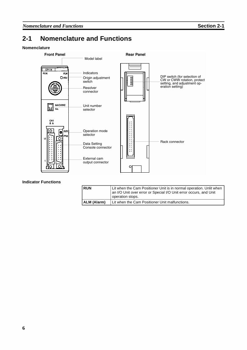
2-1 Nomenclature and FunctionsNomenclature
Indicator Functions
Front Panel Rear PanelModel label
IndicatorsOrigin adjustment switch
Resolver connector
Unit number selector
Operation mode selector
Data Setting Console connector
External cam output connector
DIP switch (for selection of CW or CWW rotation, protect setting, and adjustment op-eration setting)
Rack connector
RUN Lit when the Cam Positioner Unit is in normal operation. Unlit whenan I/O Unit over error or Special I/O Unit error occurs, and Unitoperation stops.
ALM (Alarm) Lit when the Cam Positioner Unit malfunctions.
7
Switch Settings Section 2-2
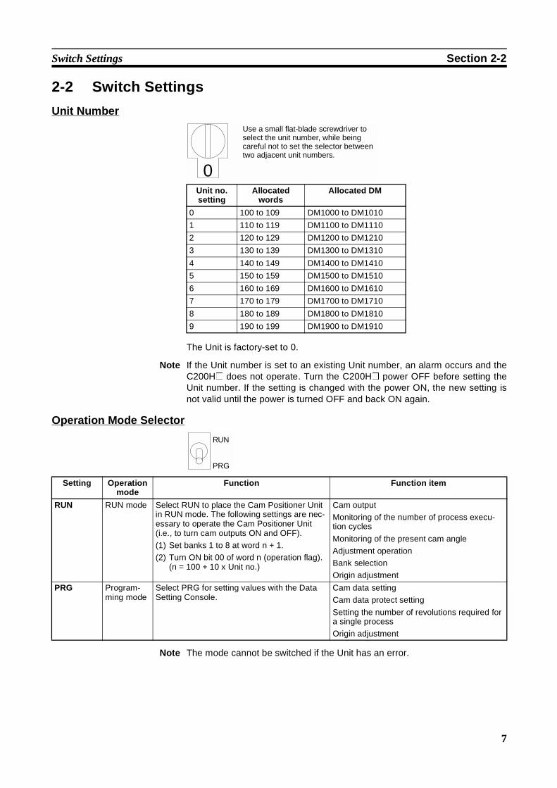
2-2 Switch Settings
Unit Number
The Unit is factory-set to 0.
Note If the Unit number is set to an existing Unit number, an alarm occurs and theC200H@ does not operate. Turn the C200H@ power OFF before setting theUnit number. If the setting is changed with the power ON, the new setting isnot valid until the power is turned OFF and back ON again.
Operation Mode Selector
Note The mode cannot be switched if the Unit has an error.
Unit no.setting
Allocatedwords
Allocated DM
0 100 to 109 DM1000 to DM1010
1 110 to 119 DM1100 to DM1110
2 120 to 129 DM1200 to DM1210
3 130 to 139 DM1300 to DM1310
4 140 to 149 DM1400 to DM1410
5 150 to 159 DM1500 to DM1510
6 160 to 169 DM1600 to DM1610
7 170 to 179 DM1700 to DM1710
8 180 to 189 DM1800 to DM1810
9 190 to 199 DM1900 to DM1910
0
Use a small flat-blade screwdriver to select the unit number, while being careful not to set the selector between two adjacent unit numbers.
RUN
PRG
Setting Operationmode
Function Function item
RUN RUN mode Select RUN to place the Cam Positioner Unitin RUN mode. The following settings are nec-essary to operate the Cam Positioner Unit(i.e., to turn cam outputs ON and OFF).
(1) Set banks 1 to 8 at word n + 1.
(2) Turn ON bit 00 of word n (operation flag).(n = 100 + 10 x Unit no.)
Cam output
Monitoring of the number of process execu-tion cycles
Monitoring of the present cam angle
Adjustment operation
Bank selection
Origin adjustment
PRG Program-ming mode
Select PRG for setting values with the DataSetting Console.
Cam data setting
Cam data protect setting
Setting the number of revolutions required fora single process
Origin adjustment
8
Wiring Section 2-3
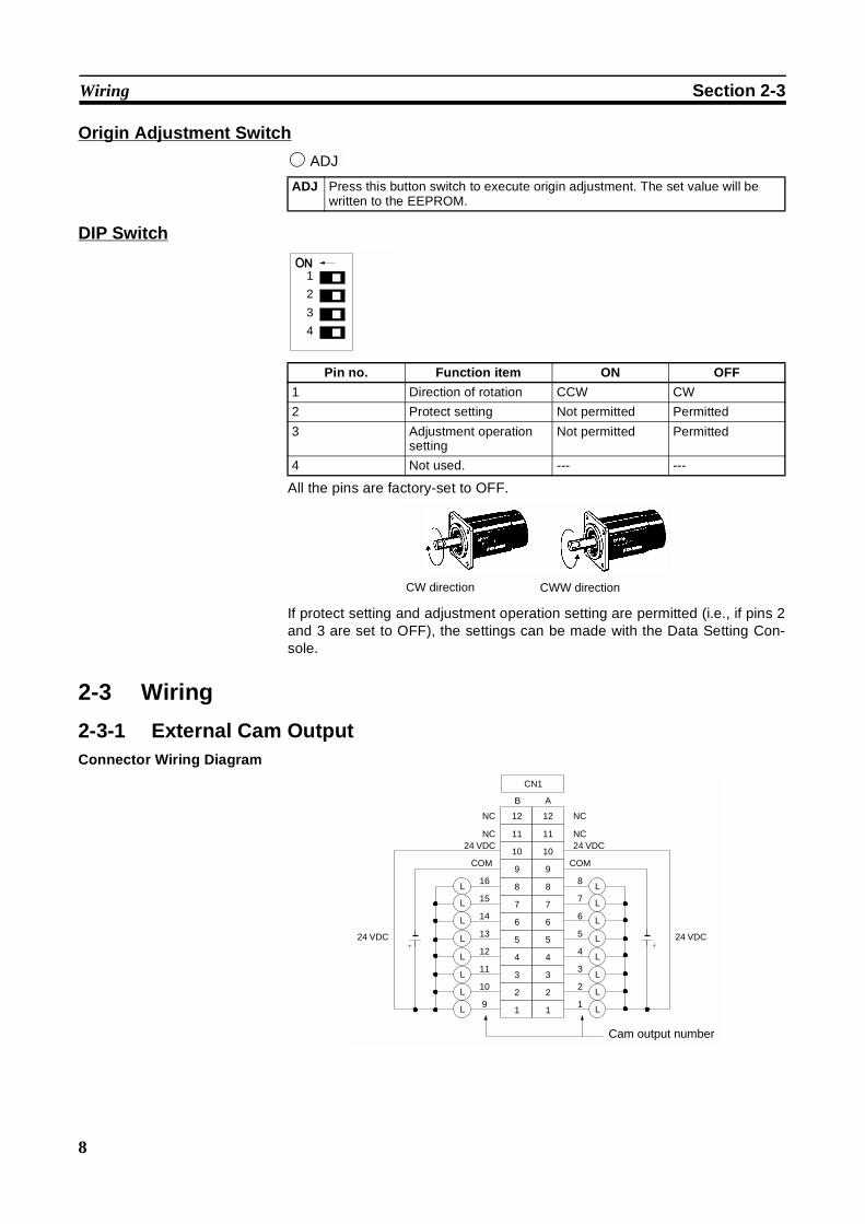
Origin Adjustment Switch
DIP Switch
All the pins are factory-set to OFF.
If protect setting and adjustment operation setting are permitted (i.e., if pins 2and 3 are set to OFF), the settings can be made with the Data Setting Con-sole.
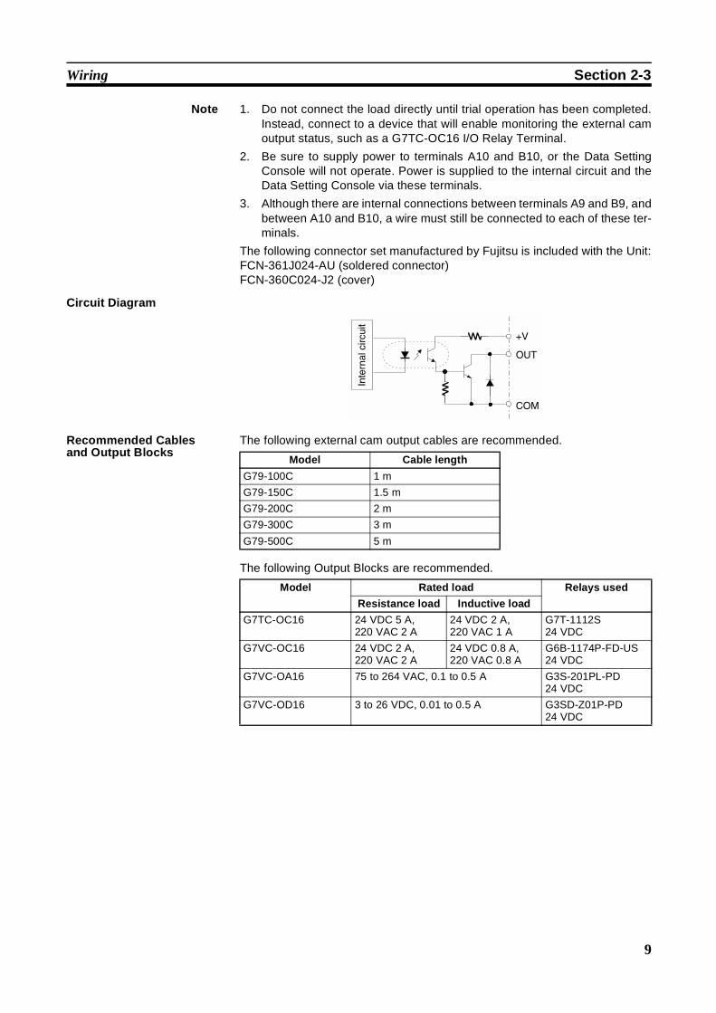
2-3 Wiring
2-3-1 External Cam OutputConnector Wiring Diagram
ADJ Press this button switch to execute origin adjustment. The set value will bewritten to the EEPROM.
ADJ
Pin no. Function item ON OFF
1 Direction of rotation CCW CW
2 Protect setting Not permitted Permitted
3 Adjustment operationsetting
Not permitted Permitted
4 Not used. --- ---
1
3
4
2
CW direction CWW direction
9
816
715
614
513
412
311
210
19
9
88
77
66
5
44
33
22
11
NC11NC 11
1024 VDC24 VDC
10
24 VDC
NC12NC 12
B A
5
L
L
L
L
L
L
L
L
L
L
L
L
L
L
L
L
CN1
COMCOM
24 VDC
Cam output number
9
Wiring Section 2-3
Note 1. Do not connect the load directly until trial operation has been completed.Instead, connect to a device that will enable monitoring the external camoutput status, such as a G7TC-OC16 I/O Relay Terminal.
2. Be sure to supply power to terminals A10 and B10, or the Data SettingConsole will not operate. Power is supplied to the internal circuit and theData Setting Console via these terminals.
3. Although there are internal connections between terminals A9 and B9, andbetween A10 and B10, a wire must still be connected to each of these ter-minals.
The following connector set manufactured by Fujitsu is included with the Unit:FCN-361J024-AU (soldered connector)FCN-360C024-J2 (cover)
Circuit Diagram
Recommended Cablesand Output Blocks
The following external cam output cables are recommended.
The following Output Blocks are recommended.
+V
OUT
COM
Inte
rnal
circ
uit
Model Cable length
G79-100C 1 m
G79-150C 1.5 m
G79-200C 2 m
G79-300C 3 m
G79-500C 5 m
Model Rated load Relays used
Resistance load Inductive load
G7TC-OC16 24 VDC 5 A,220 VAC 2 A
24 VDC 2 A,220 VAC 1 A
G7T-1112S24 VDC
G7VC-OC16 24 VDC 2 A,220 VAC 2 A
24 VDC 0.8 A,220 VAC 0.8 A
G6B-1174P-FD-US24 VDC
G7VC-OA16 75 to 264 VAC, 0.1 to 0.5 A G3S-201PL-PD24 VDC
G7VC-OD16 3 to 26 VDC, 0.01 to 0.5 A G3SD-Z01P-PD24 VDC
10
Wiring Section 2-3
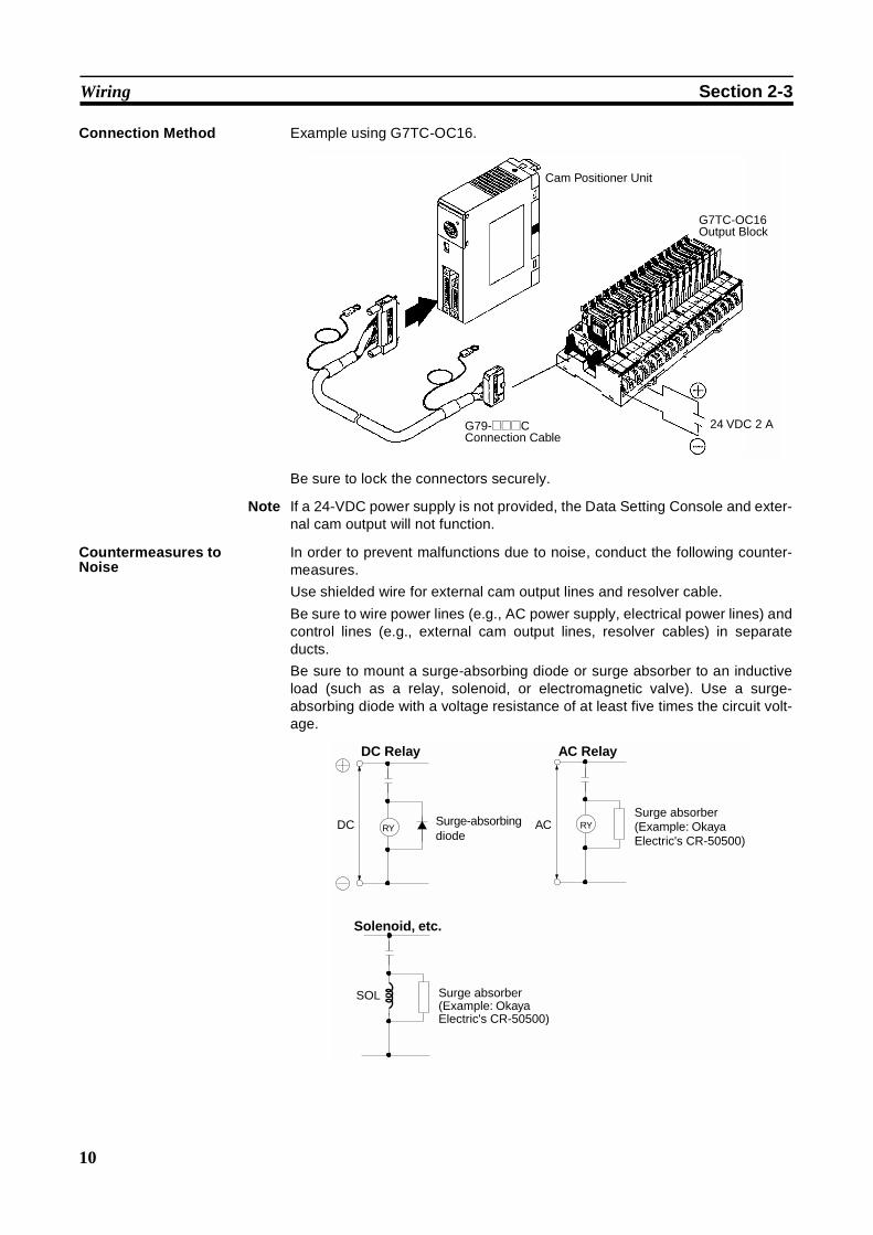
Connection Method Example using G7TC-OC16.
Be sure to lock the connectors securely.
Note If a 24-VDC power supply is not provided, the Data Setting Console and exter-nal cam output will not function.
Countermeasures toNoise
In order to prevent malfunctions due to noise, conduct the following counter-measures.
Use shielded wire for external cam output lines and resolver cable.
Be sure to wire power lines (e.g., AC power supply, electrical power lines) andcontrol lines (e.g., external cam output lines, resolver cables) in separateducts.
Be sure to mount a surge-absorbing diode or surge absorber to an inductiveload (such as a relay, solenoid, or electromagnetic valve). Use a surge-absorbing diode with a voltage resistance of at least five times the circuit volt-age.
G79-@@@C Connection Cable
24 VDC 2 A
Cam Positioner Unit
G7TC-OC16 Output Block
RYRYDC
SOL
AC
DC Relay AC Relay
Surge-absorbing diode
Surge absorber (Example: Okaya Electric's CR-50500)
Solenoid, etc.
Surge absorber (Example: Okaya Electric's CR-50500)

11
Wiring Section 2-3
2-3-2 Resolver Connection CableTo connect a resolver to the C200H-CP114 Cam Positioner Unit, use the3F88L-CR0R2A Auxiliary Connection Cable which is provided with the Unit.
To extend the cable for a 3F88L-RS17 or 3F88L-RS17T Resolver, use 3F88L-CR@@@C Extension Cable. The total length of the connection cables mustnot exceed 100 meters, or an operation error may result.
Note Secure the resolver cable so that no external force will be imposed on theauxiliary connection cables.
Inserting Connectors into the Unit
Connector Pin Wiring
20 cm
CP114ALMADJ
RUN
Connector for resolver
Insert the connector so that the cable will be pointing downward.
1
2
3
4
5
6
7
8
Sin(+)
Sin(−)Cos(+)
Cos(−)
OUT(+)
OUT(−)
1
2
3
4
5
6
7
8
Sin(+)
Sin(−)
FG
Cos(+)
Cos(−)
FG
10
11
...
15
OUT(+)
OUT(−)
FG9
Cam Positioner Unit Resolver
Connector case
Connector case
---
---------
---
---
12
Wiring Section 2-3
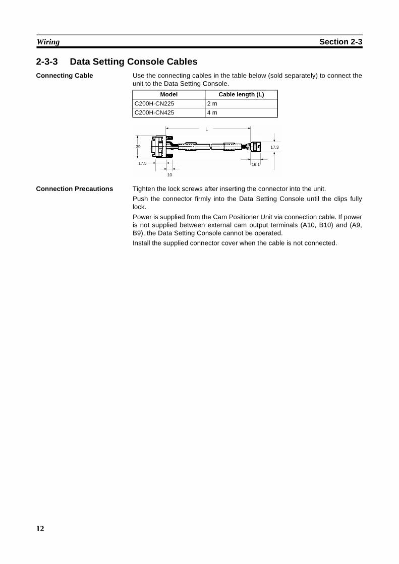
2-3-3 Data Setting Console CablesConnecting Cable Use the connecting cables in the table below (sold separately) to connect the
unit to the Data Setting Console.
Connection Precautions Tighten the lock screws after inserting the connector into the unit.
Push the connector firmly into the Data Setting Console until the clips fullylock.
Power is supplied from the Cam Positioner Unit via connection cable. If poweris not supplied between external cam output terminals (A10, B10) and (A9,B9), the Data Setting Console cannot be operated.
Install the supplied connector cover when the cable is not connected.
Model Cable length (L)
C200H-CN225 2 m
C200H-CN425 4 m
L
17.5
10
16.1
17.339

13
SECTION 3Data Setting Console Operation
This section provides the basic operating procedures of the Data Setting Console including data settings and monitoring.
3-1 Operating Procedure . . . . . . . . . . . . . . . . . . . . . . . . . . . . . . . . . . . . . . . . . . . . 14
3-2 Nomenclature and Functions . . . . . . . . . . . . . . . . . . . . . . . . . . . . . . . . . . . . . 15
3-2-1 Nomenclature . . . . . . . . . . . . . . . . . . . . . . . . . . . . . . . . . . . . . . . . . . 15
3-2-2 Functions. . . . . . . . . . . . . . . . . . . . . . . . . . . . . . . . . . . . . . . . . . . . . . 16
3-3 Data Setting and Monitoring. . . . . . . . . . . . . . . . . . . . . . . . . . . . . . . . . . . . . . 17
14
Operating Procedure Section 3-1
3-1 Operating ProcedureFollow the procedure outlined below for preparing the C200H@ prior to oper-ating the Cam Positioner Unit.
1,2,3... 1. Set the switches (Refer to 2-2 Switch Settings). Set the front and rear panelswitches according to the operating conditions.
2. Mount the Unit to the Rack. Be careful to turn off the power supply to theC200H@ before mounting the Cam Positioner Unit to the Rack or removingit from the Rack.
3. Wire the external cam outputs (Refer to 2-3 Wiring). Until the trial operationhas been completed, do not directly connect a load. Instead, connect to anobject (such as the G7TC-OC16) for which the external cam output statusis known.
4. Connect the resolver and the Data Setting Console (Refer to 2-3-2 Resolv-er Connection Cable and 2-3-3 Data Setting Console Cables). Use thespecified connection cable for connecting the resolver and the Data SettingConsole.
5. Turn ON the C200H@ and external cam output power supply. Place theC200H@ in program mode.
6. Set the data with the Data Setting Console. Set the RUN/PRG selectorswitch to PRG before setting the data.
7. Set the bank that is to be executed. Set the RUN/PRG selector switch toRUN. Set the number of the bank to be executed in word n + 1.(n = 100 + 10 x Unit no.)
8. Turn ON the Operation Flag. Turn ON bit 00 of word n (the Operation Flag).
15
Nomenclature and Functions Section 3-2
3-2 Nomenclature and Functions
3-2-1 Nomenclature
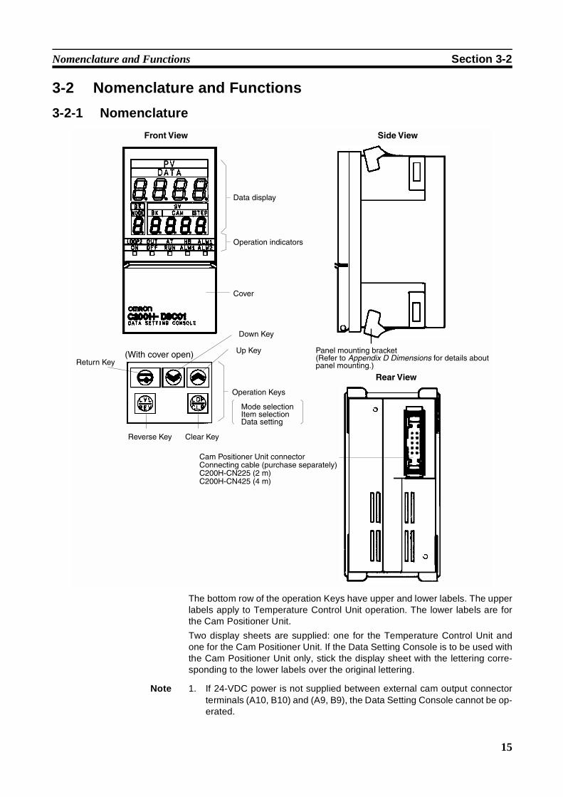
The bottom row of the operation Keys have upper and lower labels. The upperlabels apply to Temperature Control Unit operation. The lower labels are forthe Cam Positioner Unit.
Two display sheets are supplied: one for the Temperature Control Unit andone for the Cam Positioner Unit. If the Data Setting Console is to be used withthe Cam Positioner Unit only, stick the display sheet with the lettering corre-sponding to the lower labels over the original lettering.
Note 1. If 24-VDC power is not supplied between external cam output connectorterminals (A10, B10) and (A9, B9), the Data Setting Console cannot be op-erated.
Front View
Data display
Operation indicators
Cover
Side View
Panel mounting bracket (Refer to Appendix D Dimensions for details about panel mounting.)
(With cover open)
Operation Keys
Cam Positioner Unit connectorConnecting cable (purchase separately)C200H-CN225 (2 m)C200H-CN425 (4 m)
Rear View
Mode selectionItem selectionData setting
Down Key
Up Key
Return Key
Reverse Key Clear Key
16
Nomenclature and Functions Section 3-2
2. If a resolver is not connected, “e10” will blink. Should this occur, follow theprocedure outlined below to turn it off. In any case, data can still be seteven if no resolver is connected. To do that, carry out only d) and e) below.
a) Turn OFF the power supply to the C200H@.
b) Connect a resolver.
c) Turn ON the power supply to the C200H@.
d) Set the operation mode selector to PRG.
e) Press the CLR Key.
3-2-2 Functions
Display Functions
Data Display
Operation Displays
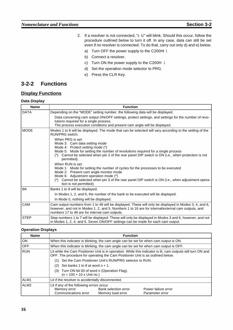
Name Function
DATA Depending on the “MODE” setting number, the following data will be displayed.
Data concerning cam output ON/OFF settings, protect settings, and settings for the number of revo-lutions required for a single process.The process execution conditions and present cam angle will be displayed.
MODE Modes 1 to 6 will be displayed. The mode that can be selected will vary according to the setting of theRUN/PRG switch.
When PRG is set:Mode 3: Cam data setting modeMode 4: Protect setting mode (*)Mode 5: Mode for setting the number of revolutions required for a single process(*) Cannot be selected when pin 2 of the rear panel DIP switch is ON (i.e., when protection is not
permitted).
When RUN is set:Mode 1: Mode for setting the number of cycles for the processes to be executedMode 2: Present cam angle monitor modeMode 6: Adjustment operation mode (*)(*) Cannot be selected when pin 3 of the rear panel DIP switch is ON (i.e., when adjustment opera-
tion is not permitted).
BK Banks 1 to 8 will be displayed.
In Modes 1, 2, and 6, the number of the bank to be executed will be displayed.
In Mode 5, nothing will be displayed.
CAM Cam output numbers from 1 to 48 will be displayed. These will only be displayed in Modes 3, 4, and 6,however, and not in Modes 1, 2, and 5. Numbers 1 to 16 are for internal/external cam outputs, andnumbers 17 to 48 are for internal cam outputs.
STEP Step numbers 1 to 7 will be displayed. These will only be displayed in Modes 3 and 6, however, and notin Modes 1, 2, 4, and 5. Seven ON/OFF settings can be made for each cam output.
Name Function
ON When this indicator is blinking, the cam angle can be set for when cam output is ON.
OFF When this indicator is blinking, the cam angle can be set for when cam output is OFF.
RUN Lit while the Cam Positioner Unit is in operation. While this indicator is lit, cam outputs will turn ON andOFF. The procedure for operating the Cam Positioner Unit is as outlined below.
(1) Set the Cam Positioner Unit’s RUN/PRG selector to RUN.
(2) Set banks 1 to 8 at word n + 1.
(3) Turn ON bit 00 of word n (Operation Flag).(n = 100 + 10 x Unit no.)
ALM1 Lit if the resolver is accidentally disconnected.
ALM2 Lit if any of the following errors occur.Memory error Bank selection error Power failure errorCommunications error Memory load error Parameter error

17
Data Setting and Monitoring Section 3-3
Operation Key Functions
3-3 Data Setting and MonitoringSetting Items
For Modes 3, 4, and 5, set the RUN/PRG selector to PRG.
Mode 4 is valid only when pin 2 of the rear panel DIP switch is OFF (i.e., whenprotection is permitted).
Mode 6 is available only when pin 3 of the rear panel DIP switch is OFF (i.e.,when adjustment operation is permitted). For Mode 6, set the RUN/PRGselector to RUN.
Name Function
Return Key When beginning a setting change, press the Return Key, the Up Key, or the Down Key. The MODEnumber will then blink. Each time the Return Key is pressed, the set value that is blinking will beentered and the next item to be set will start blinking.
Up Key When beginning a setting change, press the Return Key, the Up Key, or the Down Key. The MODEnumber will then blink. Press the Up Key to increment the number that is blinking. When making aDATA setting, press the Up Key continually to successively increment the number.
Down Key When beginning a setting change, press the Return Key, the Up Key, or the Down Key. The MODEnumber will then blink. Press the Up Key to decrement the number that is blinking. When making aDATA setting, press the Up Key continually to successively decrement the number.
Reverse Key When the Reverse Key is pressed, the setting item that is currently blinking will stop and the previousitem will start blinking. To finish making settings in a given mode, use the Reverse Key to return to theblinking MODE display and then press the Reverse Key again. The blinking display will then stay lit andthe settings will be complete.
Clear Key When the Clear Key is pressed, all data below the blinking item will be cleared. For example, if “1” isblinking for BK, all of the data for bank no. 1 will be cleared. When the Clear Key is pressed once, theitem that is to be cleared will start blinking. If the Clear Key is then pressed a second time, the data willbe cleared. To cancel the clear, press any Key other the Clear Key before pressing the Clear Key thesecond time. This function does not exist in the adjustment operation mode (mode 6). Press the ClearKey to clear an error display.
MODE Settingitem
Name Setting range
3 (Cam datasetting)
6 (Adjustmentoperation)
BK Bank no. 1 to 8
In Mode 6, the setting (i.e., the number of the bank to beexecuted) is made from the C200H@ user’s program or aperipheral device.
CAM Cam output no. 1 to 481 to 16: internal/external cam output17 to 48: Internal cam output
STEP Step no. 1 to 7
ON ON angle 0 to 359
OFF OFF angle
4 (Protect set-ting)
BK Bank no. 1 to 8
CAM Cam output no. 1 to 481 to 16: internal/external cam output17 to 48: Internal cam output
DATA Not protected “---”
Protected “pr%”
5 (Number ofrevolutionsrequired for asingleprocess)
DATA Decimal point position 2 digits to right of decimal1 digit to right of decimal0 digits to right of decimal
Set the number of resolverrevolutions required for a sin-gle process cycle.
Data 0.01 to 9.990.1 to 99.91 to 999

18
Data Setting and Monitoring Section 3-3
Monitor Items
Set the RUN/PRG selector to RUN.
Cam Setting Data andCam Outputs
The following table shows the relation between the cam data that has beenset and the cam outputs.
The cam output turns ON at the ON angle and turns OFF at the OFF angleminus 1°.Cam outputs turn ON and OFF only when the Cam Positioner Unit is in opera-tion.
The procedure for operating the Cam Positioner Unit is outlined below.
1,2,3... 1. Set the Cam Positioner Unit’s RUN/PRG selector to RUN.
2. Set banks 1 to 8 at word (n + 1).
3. Turn ON bit 00 of word n (Operation Flag).(n = 100 + 10 x Unit no.)
During operation, the RUN indicator on the Data Setting Console will remainlit.
Number of RevolutionsRequired for a SingleProcess and Monitoring ofthe Number of ProcessExecution Cycles
The relation between the Mode 5 (number of revolutions required for a singleprocess) set value and the Mode 1 (monitoring of the number of process exe-cution cycles) monitor value is as shown below.
If the number of revolutions required for a single process (i.e., the Mode 5 setvalue) is “1,” then the monitoring of the number of process execution cycles(i.e., the Mode 1 monitor value) will indicate the number of resolver revolu-tions.
The Mode 1 monitor value will also indicate the number produced per unittime.
MODE Name Function
1 Monitoring of the number of process execution cycles Displays the number of process execution cycles perunit time.
2 Monitoring of the present cam angle Monitors the present cam angle of the resolver.
Cam output no. Step no. ON angle OFF angle
1 1 90 180
2 1 0 45
2 90 135
3 180 270
3 1 180 90
0° 90° 270°180° 0° 90°Angle of rotation
Cam output 1
Cam output 2
Cam output 3
Direction of rotation
1 revolution
Mode 1 monitor value = Number of resolver revolutionsMode 5 set value
19
Data Setting and Monitoring Section 3-3
Mode Selection and Data Setting Procedure
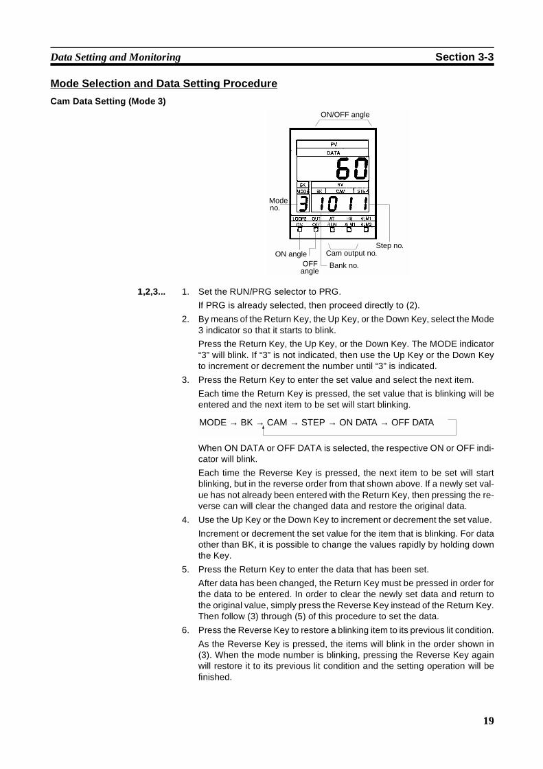
Cam Data Setting (Mode 3)
1,2,3... 1. Set the RUN/PRG selector to PRG.
If PRG is already selected, then proceed directly to (2).
2. By means of the Return Key, the Up Key, or the Down Key, select the Mode3 indicator so that it starts to blink.
Press the Return Key, the Up Key, or the Down Key. The MODE indicator“3” will blink. If “3” is not indicated, then use the Up Key or the Down Keyto increment or decrement the number until “3” is indicated.
3. Press the Return Key to enter the set value and select the next item.
Each time the Return Key is pressed, the set value that is blinking will beentered and the next item to be set will start blinking.
When ON DATA or OFF DATA is selected, the respective ON or OFF indi-cator will blink.
Each time the Reverse Key is pressed, the next item to be set will startblinking, but in the reverse order from that shown above. If a newly set val-ue has not already been entered with the Return Key, then pressing the re-verse can will clear the changed data and restore the original data.
4. Use the Up Key or the Down Key to increment or decrement the set value.
Increment or decrement the set value for the item that is blinking. For dataother than BK, it is possible to change the values rapidly by holding downthe Key.
5. Press the Return Key to enter the data that has been set.
After data has been changed, the Return Key must be pressed in order forthe data to be entered. In order to clear the newly set data and return tothe original value, simply press the Reverse Key instead of the Return Key.Then follow (3) through (5) of this procedure to set the data.
6. Press the Reverse Key to restore a blinking item to its previous lit condition.
As the Reverse Key is pressed, the items will blink in the order shown in(3). When the mode number is blinking, pressing the Reverse Key againwill restore it to its previous lit condition and the setting operation will befinished.
ON angle
Mode no.
ON/OFF angle
OFF angle
Bank no.
Cam output no.Step no.
MODE → BK → CAM → STEP → ON DATA → OFF DATA
20
Data Setting and Monitoring Section 3-3
How to Clear Data
1,2,3... 1. Follow (1) to (3) of the above procedure to cause the items that are to becleared to start blinking.
2. Press the Clear Key twice. When it is pressed the first time, all of the itemsto be cleared will start blinking.
When it is pressed the second time, all of the ON/OFF angle data will becleared for the items that are blinking. If CAM no. “1” is blinking, for exam-ple, then the ON/OFF angle data for steps 1 to 7 for cam output no. 1 willbe cleared.
To cancel a clearing operation, press any other key instead of pressing theClear Key the second time.
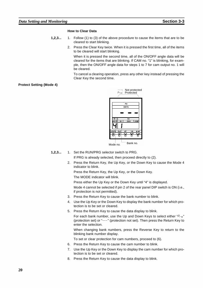
Protect Setting (Mode 4)
1,2,3... 1. Set the RUN/PRG selector switch to PRG.
If PRG is already selected, then proceed directly to (2).
2. Press the Return Key, the Up Key, or the Down Key to cause the Mode 4indicator to blink.
Press the Return Key, the Up Key, or the Down Key.
The MODE indicator will blink.
Press either the Up Key or the Down Key until “4” is displayed.
Mode 4 cannot be selected if pin 2 of the rear panel DIP switch is ON (i.e.,if protection is not permitted).
3. Press the Return Key to cause the bank number to blink.
4. Use the Up Key or the Down Key to display the bank number for which pro-tection is to be set or cleared.
5. Press the Return Key to cause the data display to blink.
For each bank number, use the Up and Down Keys to select either “pr%”(protection set) or “---” (protection not set). Then press the Return Key toenter the selection.
When changing bank numbers, press the Reverse Key to return to theblinking bank number display.
To set or clear protection for cam numbers, proceed to (6).
6. Press the Return Key to cause the cam number to blink.
7. Use the Up Key or the Down Key to display the cam number for which pro-tection is to be set or cleared.
8. Press the Return Key to cause the data display to blink.
---: Not protectedpr%: Protected
Mode no. Bank no.
21
Data Setting and Monitoring Section 3-3
9. With the Up and Down Keys, select either “pr%” or “---”.
10. Press the Return Key to enter the selection.
Repeat (6) through (10) for each cam number.
11. Press the Reverse Key to restore the blinking display to its previous lit con-dition.
When the mode number is blinking, press the Reverse Key a second timeto restore the blinking display to its previous lit condition and complete thesetting operation.
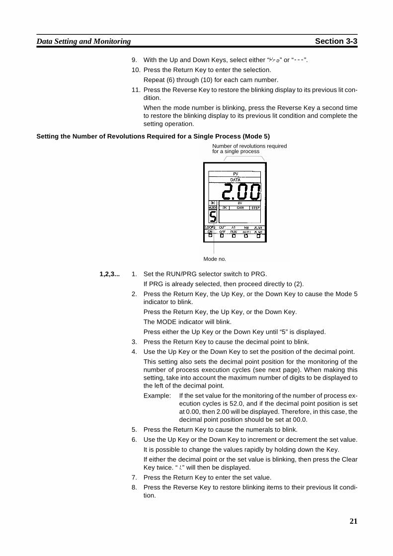
Setting the Number of Revolutions Required for a Single Process (Mode 5)
1,2,3... 1. Set the RUN/PRG selector switch to PRG.
If PRG is already selected, then proceed directly to (2).
2. Press the Return Key, the Up Key, or the Down Key to cause the Mode 5indicator to blink.
Press the Return Key, the Up Key, or the Down Key.
The MODE indicator will blink.
Press either the Up Key or the Down Key until “5” is displayed.
3. Press the Return Key to cause the decimal point to blink.
4. Use the Up Key or the Down Key to set the position of the decimal point.
This setting also sets the decimal point position for the monitoring of thenumber of process execution cycles (see next page). When making thissetting, take into account the maximum number of digits to be displayed tothe left of the decimal point.
Example: If the set value for the monitoring of the number of process ex-ecution cycles is 52.0, and if the decimal point position is setat 0.00, then 2.00 will be displayed. Therefore, in this case, thedecimal point position should be set at 00.0.
5. Press the Return Key to cause the numerals to blink.
6. Use the Up Key or the Down Key to increment or decrement the set value.
It is possible to change the values rapidly by holding down the Key.
If either the decimal point or the set value is blinking, then press the ClearKey twice. “1.” will then be displayed.
7. Press the Return Key to enter the set value.
8. Press the Reverse Key to restore blinking items to their previous lit condi-tion.
Number of revolutions required for a single process
Mode no.

22
Data Setting and Monitoring Section 3-3
If the mode number is blinking, press the Reverse Key again. The blinkingdisplay will then stay lit and the settings will be complete.
Monitoring of the Number of Process Execution Cycles (Mode 1)
1,2,3... 1. Set the RUN/PRG selector switch to RUN.
If RUN is already selected, then proceed directly to (2).
2. Press the Return Key, the Up Key, or the Down Key to cause the Mode 1indicator to blink.
Press the Return Key, the Up Key, or the Down Key.
The MODE indicator will blink.
Press either the Up Key or the Down Key until “1” is displayed.
3. Press the Return Key to enter mode “1.”
Based on the number process execution cycles set in Mode 5, the numberof process execution cycles per minute will be displayed as follows:
4. Set the bank that is to be executed.
In word n + 1 (n = 100 + 10 x Unit no.), set the number of the bank (0000to 0008) that is to be executed.
If the bank number is 0000, only the number of process execution cycles(and not the cam output) will be displayed.
When setting the number of the bank to be executed, make the setting withbit 00 of word n OFF (i.e., with the Operation Flag OFF), or turn the Oper-ation Flag OFF and then ON again after the setting has been made in wordn + 1. The setting cannot be made when the Operation Flag is ON.
Set the bank number with either the user’s program or with a peripheral de-vice such as the Programming Console.
5. Turn ON the Operation Flag.
Turn ON bit 00 of word n (the Operation Flag).
Make the setting with either the user’s program or with a peripheral devicesuch as the Programming Console.
From this point on, operations will be carried out according to the cam dataof the bank that has been set.
Number of process execution cycles per unit time
Mode no. Execution bank no. 0: No cam output 1 to 8: Bank no.
Number of process execution cycles per minute
Number of resolver revolutionsNumber of revolutions required for a single process
=

23
Data Setting and Monitoring Section 3-3
When changing the number of the bank to be executed, first make thechange in word n + 1, and then turn the Operation Flag from ON to OFF,and then ON again.
Monitoring of the Present Cam Angle (Mode 2)
1,2,3... 1. Set the RUN/PRG selector switch to RUN.
If RUN is already selected, then proceed directly to (2).
2. Press the Return Key, the Up Key, or the Down Key to cause the Mode 2indicator to blink.
Press the Return Key, the Up Key, or the Down Key.
The MODE indicator will blink.
Press either the Up Key or the Down Key until “2” is displayed.
3. Press the Return Key to enter mode “2.”
During operation, cam outputs will turn ON and OFF in response to thepresent cam angle, according to the ON and OFF angle setting data of thebank that is executed.
If the bank number is set to “0,” then there will be no cam output.
Adjustment Operation (Mode 6)
1,2,3... 1. Set the RUN/PRG selector switch to RUN.
If RUN is already selected, then proceed directly to (2).
Present cam angle
Mode no.Execution bank no. 0: No cam output 1 to 8: Bank no.
ON/OFF angle
Mode no.
ON angle
OFF angle Execution bank no.
Step no.Cam output no.
24
Data Setting and Monitoring Section 3-3
2. Press the Return Key, the Up Key, or the Down Key to cause the Mode 6indicator to blink.
Mode 6 cannot be selected when pin 3 of the Cam Positioner Unit’s rearpanel DIP switch is ON (i.e., when adjustment operation is not permitted).
3. From this point on, follow (3) through (6) of the setting procedure for Mode3.
The number of the bank to be executed will be displayed in BK, so “BK”cannot be selected.
When changing the number of the bank to be executed, make the settingin word n + 1 by means of the user’s program or a peripheral device suchas the Programming Console, and then turn bit 00 of word n (the OperationFlag) from ON to OFF, and then ON again.
Origin Adjustment The term “origin adjustment” refers to the matching of the resolver origin tothe mechanical origin. For example, if the present cam angle is 130° and ifyou want this angle position to match the mechanical origin of 0°, then originadjustment can be used.
Origin Adjustment Methods
Either of the methods described below can be used for origin adjustment.When origin adjustment is executed, “7” will blink three times in “MODE,” andthe resolver absolute angle will blink three times in “DATA.” When originadjustment is finished, the previous display will be restored.
Press the button on the front panel of the Cam Positioner Unit. The originadjustment value will then be written to the EEPROM in the Unit.
or Turn the Origin Adjustment Flag (bit 01 of word n) from OFF to ON.
When the origin adjustment has been completed, turn ON the Origin Ad-justment Completion Flag (bit 05 of word n + 8). This flag will automaticallyturn OFF when the Origin Adjustment Flag turns OFF.
Origin adjustment will be written to the RAM in the Unit according to theOrigin Adjustment Flag.
When entering the origin adjustment, turn the EEPROM Write Flag (bit 02of word n) from OFF to ON. The origin adjustment value will then be writtento EEPROM.
Note Because there is a limit to the number of times that data can be written toEEPROM (approx. 10,000 times), the second of the two methods describedabove is recommended for origin adjustment.
During resolver rotation, origin adjustment will not be effective even if it is exe-cuted.
If origin adjustment is attempted while the Unit has an error, the origin adjust-ment will be executed after the error is cleared.
25
SECTION 4PC Memory Allocation and Programming
This section provides the C200H@ PC’s memory allocation for the Cam Positioner Unit. Basic programming proceduresand examples are also provided.
4-1 Memory Allocation . . . . . . . . . . . . . . . . . . . . . . . . . . . . . . . . . . . . . . . . . . . . . 26
4-1-1 Bit Allocation Chart . . . . . . . . . . . . . . . . . . . . . . . . . . . . . . . . . . . . . 27
4-1-2 Bit Allocation Data Contents . . . . . . . . . . . . . . . . . . . . . . . . . . . . . . 27
4-1-3 DM Allocation Chart . . . . . . . . . . . . . . . . . . . . . . . . . . . . . . . . . . . . 31
4-1-4 DM Allocation/Data Contents . . . . . . . . . . . . . . . . . . . . . . . . . . . . . 32
4-2 Peripheral Device Operations and Data Setting . . . . . . . . . . . . . . . . . . . . . . . 32
4-3 Program Examples . . . . . . . . . . . . . . . . . . . . . . . . . . . . . . . . . . . . . . . . . . . . . 37
4-3-1 Setting the Bank Number and Starting Operation . . . . . . . . . . . . . . 37
4-3-2 Setting Cam ON/OFF Data. . . . . . . . . . . . . . . . . . . . . . . . . . . . . . . . 38
4-3-3 Program Example to Set 48-point Cam ON/OFF Data . . . . . . . . . . 39
4-3-4 Monitoring Cam ON/OFF Data . . . . . . . . . . . . . . . . . . . . . . . . . . . . 43
4-3-5 Setting the Number of Revolutions per Process . . . . . . . . . . . . . . . . 44
26
Memory Allocation Section 4-1
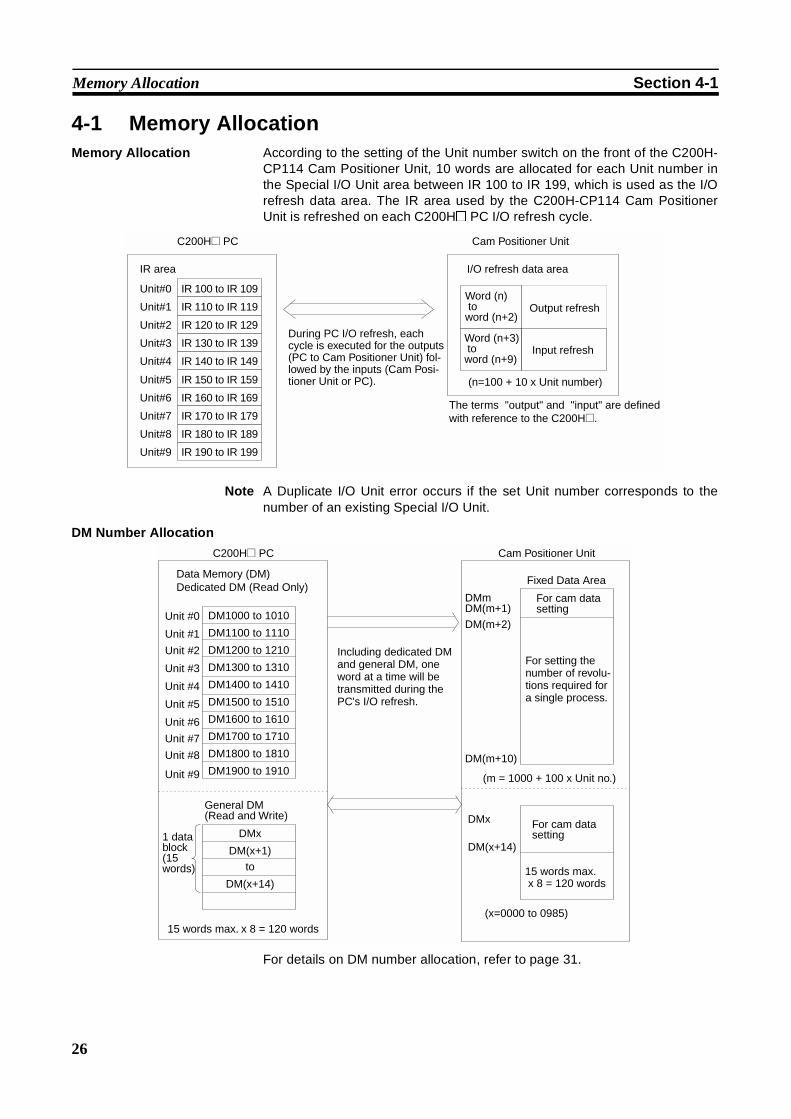
4-1 Memory AllocationMemory Allocation According to the setting of the Unit number switch on the front of the C200H-
CP114 Cam Positioner Unit, 10 words are allocated for each Unit number inthe Special I/O Unit area between IR 100 to IR 199, which is used as the I/Orefresh data area. The IR area used by the C200H-CP114 Cam PositionerUnit is refreshed on each C200H@ PC I/O refresh cycle.
Note A Duplicate I/O Unit error occurs if the set Unit number corresponds to thenumber of an existing Special I/O Unit.
DM Number Allocation
For details on DM number allocation, refer to page 31.
IR area
Unit#0 IR 100 to IR 109
Unit#1 IR 110 to IR 119
Unit#2 IR 120 to IR 129
Unit#3 IR 130 to IR 139
Unit#4 IR 140 to IR 149
Unit#5 IR 150 to IR 159
Unit#6 IR 160 to IR 169
Unit#7 IR 170 to IR 179
Unit#8 IR 180 to IR 189
Unit#9 IR 190 to IR 199
During PC I/O refresh, each cycle is executed for the outputs (PC to Cam Positioner Unit) fol-lowed by the inputs (Cam Posi-tioner Unit or PC).
Cam Positioner Unit
I/O refresh data area
Word (n) to word (n+2)
Output refresh
Word (n+3) to word (n+9)
Input refresh
(n=100 + 10 x Unit number)
The terms "output" and "input" are defined with reference to the C200H@.
C200H@ PC
DMx
DM(x+1)
to
DM(x+14)
DM1000 to 1010
DM1100 to 1110
DM1200 to 1210
DM1300 to 1310
DM1400 to 1410
DM1500 to 1510
DM1600 to 1610
DM1700 to 1710
DM1800 to 1810
DM1900 to 1910
(x=0000 to 0985)
DMm DM(m+1)
DM(m+2)
DM(m+10)
DMx
DM(x+14)
Data Memory (DM)Dedicated DM (Read Only)
Unit #0
Unit #1
Unit #2
Unit #3
Unit #4
Unit #5
Unit #6
Unit #7
Unit #8
Unit #9
Including dedicated DM and general DM, one word at a time will be transmitted during the PC's I/O refresh.
Cam Positioner UnitC200H@ PC
Fixed Data Area
General DM (Read and Write)
15 words max. x 8 = 120 words
1 data block (15 words)
For cam data setting
For setting the number of revolu-tions required for a single process.
(m = 1000 + 100 x Unit no.)
For cam data setting
15 words max. x 8 = 120 words
27
Memory Allocation Section 4-1
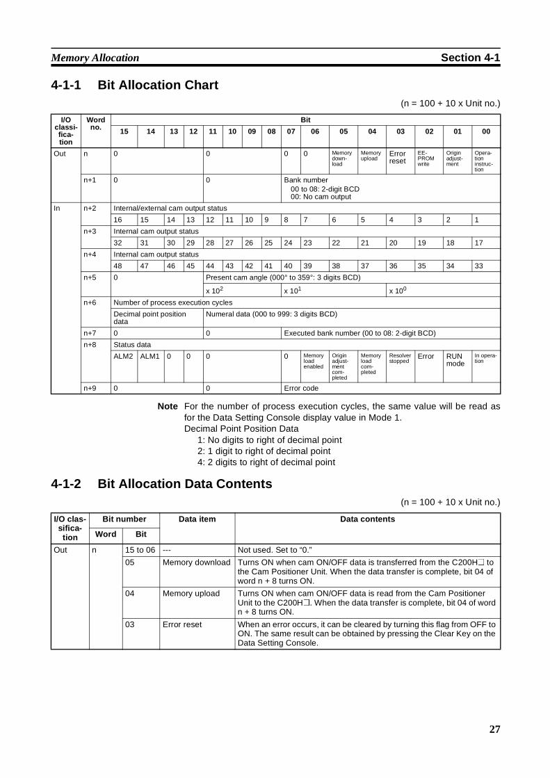
4-1-1 Bit Allocation Chart(n = 100 + 10 x Unit no.)
Note For the number of process execution cycles, the same value will be read asfor the Data Setting Console display value in Mode 1.Decimal Point Position Data
1: No digits to right of decimal point2: 1 digit to right of decimal point4: 2 digits to right of decimal point
4-1-2 Bit Allocation Data Contents(n = 100 + 10 x Unit no.)
I/Oclassi-fica-tion
Wordno.
Bit
15 14 13 12 11 10 09 08 07 06 05 04 03 02 01 00
Out n 0 0 0 0 Memorydown-load
Memoryupload
Errorreset
EE-PROMwrite
Originadjust-ment
Opera-tioninstruc-tion
n+1 0 0 Bank number00 to 08: 2-digit BCD00: No cam output
In n+2 Internal/external cam output status
16 15 14 13 12 11 10 9 8 7 6 5 4 3 2 1
n+3 Internal cam output status
32 31 30 29 28 27 26 25 24 23 22 21 20 19 18 17
n+4 Internal cam output status
48 47 46 45 44 43 42 41 40 39 38 37 36 35 34 33
n+5 0 Present cam angle (000° to 359°: 3 digits BCD)
x 102 x 101 x 100
n+6 Number of process execution cycles
Decimal point positiondata
Numeral data (000 to 999: 3 digits BCD)
n+7 0 0 Executed bank number (00 to 08: 2-digit BCD)
n+8 Status data
ALM2 ALM1 0 0 0 0 Memoryloadenabled
Originadjust-mentcom-pleted
Memoryloadcom-pleted
Resolverstopped
Error RUNmode
In opera-tion
n+9 0 0 Error code
I/O clas-sifica-tion
Bit number Data item Data contents
Word Bit
Out n 15 to 06 --- Not used. Set to “0.”
05 Memory download Turns ON when cam ON/OFF data is transferred from the C200H@ tothe Cam Positioner Unit. When the data transfer is complete, bit 04 ofword n + 8 turns ON.
04 Memory upload Turns ON when cam ON/OFF data is read from the Cam PositionerUnit to the C200H@. When the data transfer is complete, bit 04 of wordn + 8 turns ON.
03 Error reset When an error occurs, it can be cleared by turning this flag from OFF toON. The same result can be obtained by pressing the Clear Key on theData Setting Console.
28
Memory Allocation Section 4-1
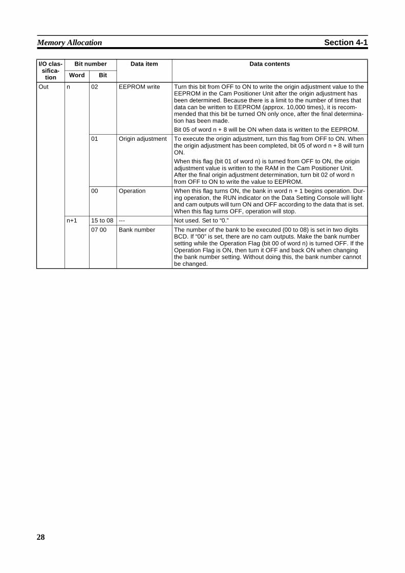
Out n 02 EEPROM write Turn this bit from OFF to ON to write the origin adjustment value to theEEPROM in the Cam Positioner Unit after the origin adjustment hasbeen determined. Because there is a limit to the number of times thatdata can be written to EEPROM (approx. 10,000 times), it is recom-mended that this bit be turned ON only once, after the final determina-tion has been made.
Bit 05 of word n + 8 will be ON when data is written to the EEPROM.
01 Origin adjustment To execute the origin adjustment, turn this flag from OFF to ON. Whenthe origin adjustment has been completed, bit 05 of word n + 8 will turnON.
When this flag (bit 01 of word n) is turned from OFF to ON, the originadjustment value is written to the RAM in the Cam Positioner Unit.After the final origin adjustment determination, turn bit 02 of word nfrom OFF to ON to write the value to EEPROM.
00 Operation When this flag turns ON, the bank in word n + 1 begins operation. Dur-ing operation, the RUN indicator on the Data Setting Console will lightand cam outputs will turn ON and OFF according to the data that is set.When this flag turns OFF, operation will stop.
n+1 15 to 08 --- Not used. Set to “0.”
07 00 Bank number The number of the bank to be executed (00 to 08) is set in two digitsBCD. If “00” is set, there are no cam outputs. Make the bank numbersetting while the Operation Flag (bit 00 of word n) is turned OFF. If theOperation Flag is ON, then turn it OFF and back ON when changingthe bank number setting. Without doing this, the bank number cannotbe changed.
I/O clas-sifica-tion
Bit number Data item Data contents
Word Bit
29
Memory Allocation Section 4-1
I/Oclassifi-cation
Bit number Data item Data contents
Word Bit
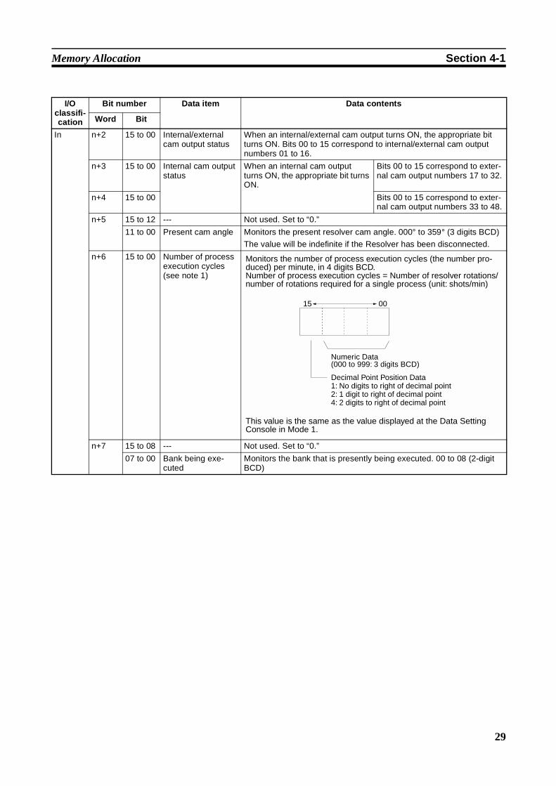
In n+2 15 to 00 Internal/externalcam output status
When an internal/external cam output turns ON, the appropriate bitturns ON. Bits 00 to 15 correspond to internal/external cam outputnumbers 01 to 16.
n+3 15 to 00 Internal cam outputstatus
When an internal cam outputturns ON, the appropriate bit turnsON.
Bits 00 to 15 correspond to exter-nal cam output numbers 17 to 32.
n+4 15 to 00 Bits 00 to 15 correspond to exter-nal cam output numbers 33 to 48.
n+5 15 to 12 --- Not used. Set to “0.”
11 to 00 Present cam angle Monitors the present resolver cam angle. 000° to 359° (3 digits BCD)
The value will be indefinite if the Resolver has been disconnected.
n+6 15 to 00 Number of processexecution cycles(see note 1)
n+7 15 to 08 --- Not used. Set to “0.”
07 to 00 Bank being exe-cuted
Monitors the bank that is presently being executed. 00 to 08 (2-digitBCD)
Monitors the number of process execution cycles (the number pro-duced) per minute, in 4 digits BCD.Number of process execution cycles = Number of resolver rotations/number of rotations required for a single process (unit: shots/min)
This value is the same as the value displayed at the Data Setting Console in Mode 1.
15 00
Numeric Data(000 to 999: 3 digits BCD)
Decimal Point Position Data1: No digits to right of decimal point 2: 1 digit to right of decimal point 4: 2 digits to right of decimal point

30
Memory Allocation Section 4-1
Note 1. Data other than 0 may be output even if the Resolver is not operating whenthe power is turned ON, the Special I/O Unit has been reset, or origin ad-justment has been executed.
2. May turn OFF even if the Resolver is not operating when the power isturned ON, the Special I/O Unit has been reset, origin adjustment hasbeen executed, or the Resolver has been disconnected.
In n+8 15 ALM2 The ALM 2 bit turns ON and theALM 2 indicator on the Data Set-ting Console lights when any ofthe following errors occur.
Memory errorBank change errorCommunications errorData transfer errorPower failure errorParameter error
When the errors on the left occur,the following conditions occursimultaneously.
The ALM indicator lights on thefront panel of the Cam Posi-tioner Unit.
Bit 02 of word n + 8 turns ON.
The error code is output to wordn + 9.
14 ALM1 The ALM 1 bit turns ON if an erroroccurs due to the resolver beingdisconnected. At that time, theALM 1 indicator on the Data Set-ting Console lights.
13 to 07 --- Not used. Set to “0.”
06 Memory loadenabled
When this flag is ON, memory downloading and uploading is possible.This flag is ON when the Data Setting Console display is lit, and OFFwhen the display is blinking. (The display blinks while data is beingset.)
05 Origin adjustmentcompleted
Turns ON when origin adjustment is completed, based on the OriginAdjustment Flag (bit 01 of word n) or the EEPROM Write Flag (bit 02of word n) turning ON, and turns OFF based on these bits turning OFF.
04 Memory loadcompleted
Turns ON when memory downloading (bit 05 of word n) or memoryuploading (bit 04 of word n) is completed, and OFF based on either ofthese bits turning OFF.
03 Resolver stopped(see note 2)
ON while resolver rotation is stopped (4 r/min or less), and OFF duringrotation.
02 Error Normally OFF. Turns ON when a Cam Positioner Unit error occurs. Atthat time, the ALM indicator on the front panel of the Cam PositionerUnit lights.
01 RUN mode ON when the operation mode selector on the front panel of the CamPositioner Unit is set to RUN, and OFF when the selector is set toPRG.
00 In operation ON during operation (i.e., when the Operation Flag, bit 00 of word n, isON).
n+9 15 to 12 --- Not used. Set to “0.”
11 to 00 Error code When errors occur, the following codes are output. (2-digit BCD)01: Memory error ALM202: Communications error ALM203: Power failure error ALM220: Bank change error ALM221: Data transfer error ALM222: Parameter error ALM210: Resolver disconnection error ALM1
For details, refer to the SECTION 5 Troubleshooting.
I/Oclassifi-cation
Bit number Data item Data contents
Word Bit
31
Memory Allocation Section 4-1
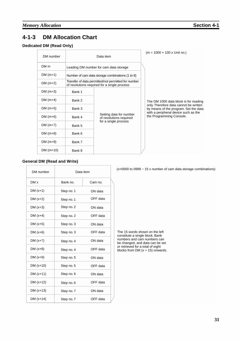
4-1-3 DM Allocation ChartDedicated DM (Read Only)
General DM (Read and Write)
DM m
DM (m+1)
DM (m+2)
DM (m+3)
DM (m+4)
DM (m+5)
DM (m+6)
DM (m+7)
DM (m+8)
DM (m+9)
DM (m+10)
(m = 1000 + 100 x Unit no.)DM number Data item
Leading DM number for cam data storage
Number of cam data storage combinations (1 to 8)
Transfer of data permitted/not permitted for number of revolutions required for a single process
Bank 1
Bank 2
Bank 3
Bank 4
Bank 5
Bank 6
Bank 7
Bank 8
Setting data for number of revolutions required for a single process
The DM 1000 data block is for reading only. Therefore data cannot be written by means of the program. Set the data with a peripheral device such as the the Programming Console.
DM x
DM (x+1)
DM (x+2)
DM (x+3)
DM (x+4)
DM (x+5)
DM (x+6)
DM (x+7)
DM (x+8)
DM (x+9)
DM (x+10)
DM (x+11)
DM (x+12)
DM (x+13)
DM (x+14)
(x=0000 to 0999 − 15 x number of cam data storage combinations)
Bank no. Cam no.
Step no. 1
Step no. 1
Step no. 2
Step no. 2
Step no. 3
Step no. 3
Step no. 4
Step no. 4
Step no. 5
Step no. 5
Step no. 6
Step no. 6
Step no. 7
Step no. 7
ON data
OFF data
ON data
ON data
ON data
ON data
ON data
ON data
OFF data
OFF data
OFF data
OFF data
OFF data
OFF data
DM number Data item
The 15 words shown on the left constitute a single block. Bank numbers and cam numbers can be changed, and data can be set or retrieved for a total of eight blocks from DM (x + 15) onwards.
32
Peripheral Device Operations and Data Setting Section 4-2
4-1-4 DM Allocation/Data ContentsDedicated DM (m = 1000 + 100 x Unit no.)
General DM (x=0000 to 0985)
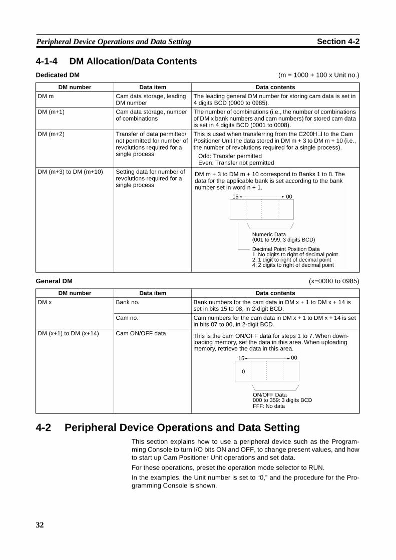
4-2 Peripheral Device Operations and Data SettingThis section explains how to use a peripheral device such as the Program-ming Console to turn I/O bits ON and OFF, to change present values, and howto start up Cam Positioner Unit operations and set data.
For these operations, preset the operation mode selector to RUN.
In the examples, the Unit number is set to “0,” and the procedure for the Pro-gramming Console is shown.
DM number Data item Data contents
DM m Cam data storage, leadingDM number
The leading general DM number for storing cam data is set in4 digits BCD (0000 to 0985).
DM (m+1) Cam data storage, numberof combinations
The number of combinations (i.e., the number of combinationsof DM x bank numbers and cam numbers) for stored cam datais set in 4 digits BCD (0001 to 0008).
DM (m+2) Transfer of data permitted/not permitted for number ofrevolutions required for asingle process
This is used when transferring from the C200H@ to the CamPositioner Unit the data stored in DM m + 3 to DM m + 10 (i.e.,the number of revolutions required for a single process).
Odd: Transfer permittedEven: Transfer not permitted
DM (m+3) to DM (m+10) Setting data for number ofrevolutions required for asingle process
DM m + 3 to DM m + 10 correspond to Banks 1 to 8. The data for the applicable bank is set according to the bank number set in word n + 1.
15 00
Numeric Data(001 to 999: 3 digits BCD)
Decimal Point Position Data1: No digits to right of decimal point 2: 1 digit to right of decimal point 4: 2 digits to right of decimal point
DM number Data item Data contents
DM x Bank no. Bank numbers for the cam data in DM x + 1 to DM x + 14 isset in bits 15 to 08, in 2-digit BCD.
Cam no. Cam numbers for the cam data in DM x + 1 to DM x + 14 is setin bits 07 to 00, in 2-digit BCD.
DM (x+1) to DM (x+14) Cam ON/OFF data This is the cam ON/OFF data for steps 1 to 7. When down-loading memory, set the data in this area. When uploading memory, retrieve the data in this area.
0
15 00
ON/OFF Data000 to 359: 3 digits BCDFFF: No data
33
Peripheral Device Operations and Data Setting Section 4-2
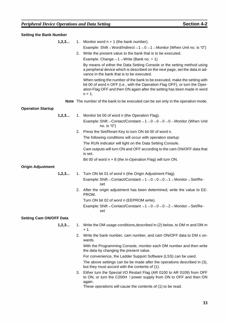
Setting the Bank Number
1,2,3... 1. Monitor word n + 1 (the bank number).
Example: Shift→Word/Indirect→1→0→1→Monitor (When Unit no. is “0”)
2. Write the present value to the bank that is to be executed.
Example: Change→1→Write (Bank no. = 1)
By means of either the Data Setting Console or the setting method usinga peripheral device which is described on the next page, set the data in ad-vance in the bank that is to be executed.
When setting the number of the bank to be executed, make the setting withbit 00 of word n OFF (i.e., with the Operation Flag OFF), or turn the Oper-ation Flag OFF and then ON again after the setting has been made in wordn + 1.
Note The number of the bank to be executed can be set only in the operation mode.
Operation Startup
1,2,3... 1. Monitor bit 00 of word n (the Operation Flag).
Example: Shift→Contact/Constant→1→0→0→0→0→Monitor (When Unitno. is “0”)
2. Press the Set/Reset Key to turn ON bit 00 of word n.
The following conditions will occur with operation startup:
The RUN indicator will light on the Data Setting Console.
Cam outputs will turn ON and OFF according to the cam ON/OFF data thatis set.
Bit 00 of word n + 8 (the in-Operation Flag) will turn ON.
Origin Adjustment
1,2,3... 1. Turn ON bit 01 of word n (the Origin Adjustment Flag).
Example: Shift→Contact/Constant→1→0→0→0→1→Monitor→Set/Re-set
2. After the origin adjustment has been determined, write the value to EE-PROM.
Turn ON bit 02 of word n (EEPROM write).
Example: Shift→Contact/Constant→1→0→0→0→2→Monitor→Set/Re-set
Setting Cam ON/OFF Data
1,2,3... 1. Write the DM usage conditions,described in (2) below, to DM m and DM m+ 1.
2. Write the bank number, cam number, and cam ON/OFF data to DM x on-wards.
With the Programming Console, monitor each DM number and then writethe data by changing the present value.
For convenience, the Ladder Support Software (LSS) can be used.
The above settings can be be made after the operations described in (3),but they must accord with the contents of (1).
3. Either turn the Special I/O Restart Flag (AR 0100 to AR 0109) from OFFto ON, or turn the C200H@ power supply from ON to OFF and then ONagain.These operations will cause the contents of (1) to be read.

34
Peripheral Device Operations and Data Setting Section 4-2
4. Turn the Memory Download Flag (bit 05 of word n) from OFF to ON.
This operation will begin the transfer to the Cam Positioner Unit of the datafrom DM x onward.
Data will be transferred one DM word at a time.
Verify the end of the transfer with the Memory Load Completed Flag (bit 04of word n + 8).
After bit 04 of word n + 8 has been turned ON, it will automatically turn OFFwhen bit 05 of word n turns OFF.
Note Memory downloading can only be executed when the memory load enabledflag (bit 06 of word n + 8) is ON. (When this bit is ON, the Data Setting Con-sole display will be lit.) This is independent of the operation mode selector set-ting and the operating/stopped setting.
Example of Setting Cam ON/OFF Data
Set the following cam ON/OFF data so that the bank number = 1 and the camnumber = 1.
Assume that the Unit number is 0 and that the general DM words to be usedbegin at DM 0100.
1,2,3... 1. Set the data shown above.
2. Turn the Special I/O Restart Flag (AR 0100) from OFF to ON. (Or else turnthe C200H@ power supply from ON to OFF and then back ON.)
OFFON
OFFON
Memory download (bit 05 of word n)
Memory load completed (bit 04 of word n + 8)
OFFONCam data
0°30° 50° 80° 115° 150° 200° 260° 320°0°
DM1000
DM1001
0100
0001
DM0100
DM0101
0101
0030
DM0102 0050
DM0103 0080
DM0104 0115
DM0105 0150
DM0106 0200
DM0107 0260
DM0108 0320
DM0109 0000
...
DM0114 0000
01 01
Dedicated DM
Leading DM number for cam data storage
General DM
Step 1
Step 2
Step 3
Step 4
Number of cam data storage combinations
Cam no.
Bank no.
For each step, set the ON data first and then the OFF data.
If the steps are not to be used, set either "0000" or "0FFF."
...
35
Peripheral Device Operations and Data Setting Section 4-2
3. Turn the Memory Download Flag (10005) from OFF to ON.
4. Monitor the memory load completed flag (10804), and wait until it turnsON. When it turns ON, the transfer will have been completed.
5. Turn OFF bit 10005. When this bit is turned OFF, bit 10804 will turn OFFautomatically.
Retrieving Cam ON/OFF Data
1,2,3... 1. Write into DM m and DM m + 1 the DM usage conditions described in (2)below.
2. Write the bank number and cam number for the data to be retrieved in DMx.Data from a maximum of eight blocks (combinations of bank numbers andcam numbers) can be retrieved, so the combinations that are to be re-trieved should be set for each block in 15 words from DM x.The above settings can be be made after the operations described in (3),but they must accord with the contents of (1).
3. Either turn the Special I/O Restart Flag (AR 0100 to AR 0109) from OFFto ON, or turn the C200H@ power supply from ON to OFF and then ONagain.These operations will cause the contents of (1) to be read.
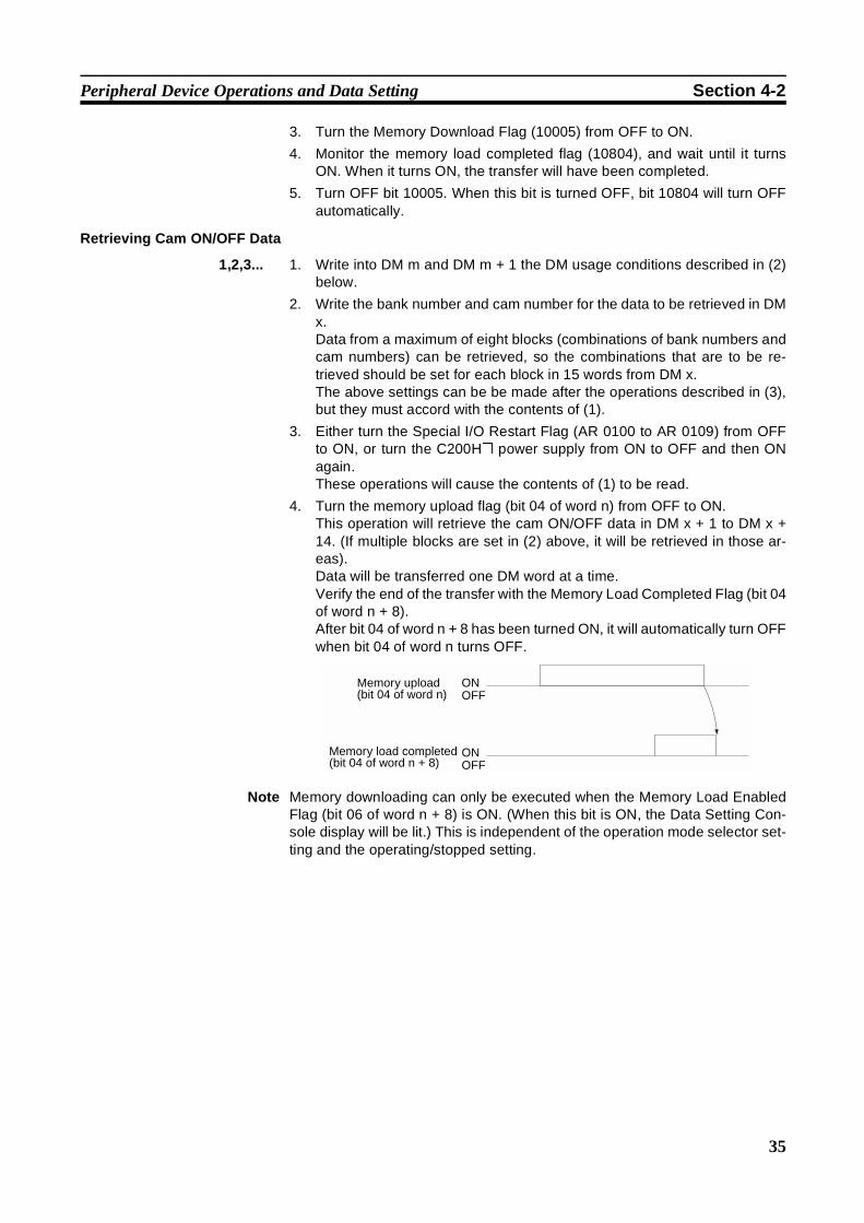
4. Turn the memory upload flag (bit 04 of word n) from OFF to ON.This operation will retrieve the cam ON/OFF data in DM x + 1 to DM x +14. (If multiple blocks are set in (2) above, it will be retrieved in those ar-eas).Data will be transferred one DM word at a time.Verify the end of the transfer with the Memory Load Completed Flag (bit 04of word n + 8).After bit 04 of word n + 8 has been turned ON, it will automatically turn OFFwhen bit 04 of word n turns OFF.
Note Memory downloading can only be executed when the Memory Load EnabledFlag (bit 06 of word n + 8) is ON. (When this bit is ON, the Data Setting Con-sole display will be lit.) This is independent of the operation mode selector set-ting and the operating/stopped setting.
Memory upload (bit 04 of word n) OFF
ON
OFFONMemory load completed
(bit 04 of word n + 8)
36
Peripheral Device Operations and Data Setting Section 4-2
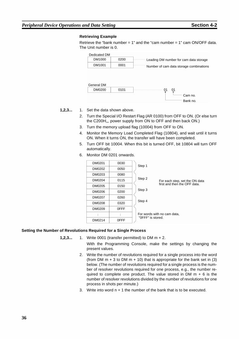
Retrieving Example
Retrieve the “bank number = 1” and the “cam number = 1” cam ON/OFF data.The Unit number is 0.
1,2,3... 1. Set the data shown above.
2. Turn the Special I/O Restart Flag (AR 0100) from OFF to ON. (Or else turnthe C200H@ power supply from ON to OFF and then back ON.)
3. Turn the memory upload flag (10004) from OFF to ON.
4. Monitor the Memory Load Completed Flag (10804), and wait until it turnsON. When it turns ON, the transfer will have been completed.
5. Turn OFF bit 10004. When this bit is turned OFF, bit 10804 will turn OFFautomatically.
6. Monitor DM 0201 onwards.
Setting the Number of Revolutions Required for a Single Process
1,2,3... 1. Write 0001 (transfer permitted) to DM m + 2.
With the Programming Console, make the settings by changing thepresent values.
2. Write the number of revolutions required for a single process into the word(from DM m + 3 to DM m + 10) that is appropriate for the bank set in (3)below. (The number of revolutions required for a single process is the num-ber of resolver revolutions required for one process, e.g., the number re-quired to complete one product. The value stored in DM m + 6 is thenumber of resolver revolutions divided by the number of revolutions for oneprocess in shots per minute.)
3. Write into word n + 1 the number of the bank that is to be executed.
DM1000
DM1001
0200
0001
DM0200 0101 01 01
Dedicated DM
Leading DM number for cam data storage
General DM
Number of cam data storage combinations
Cam no.
Bank no.
For words with no cam data, "0FFF" is stored.
DM0201 0030
DM0202 0050
DM0203 0080
DM0204 0115
DM0205 0150
DM0206 0200
DM0207 0260
DM0208 0320
DM0209 0FFF
...
DM0214 0FFF
Step 1
Step 2
Step 3
Step 4
For each step, set the ON data first and then the OFF data.
...
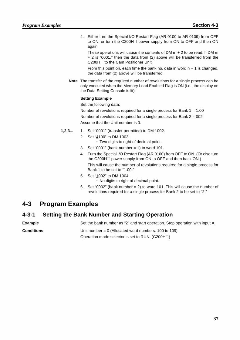
37
Program Examples Section 4-3
4. Either turn the Special I/O Restart Flag (AR 0100 to AR 0109) from OFFto ON, or turn the C200H@ power supply from ON to OFF and then ONagain.
These operations will cause the contents of DM m + 2 to be read. If DM m+ 2 is “0001,” then the data from (2) above will be transferred from theC200H@ to the Cam Positioner Unit.
From this point on, each time the bank no. data in word n + 1 is changed,the data from (2) above will be transferred.
Note The transfer of the required number of revolutions for a single process can beonly executed when the Memory Load Enabled Flag is ON (i.e., the display onthe Data Setting Console is lit).
Setting Example
Set the following data:
Number of revolutions required for a single process for Bank 1 = 1.00
Number of revolutions required for a single process for Bank 2 = 002
Assume that the Unit number is 0.
1,2,3... 1. Set “0001” (transfer permitted) to DM 1002.
2. Set “4100” to DM 1003.↑ Two digits to right of decimal point.
3. Set “0001” (bank number = 1) to word 101.
4. Turn the Special I/O Restart Flag (AR 0100) from OFF to ON. (Or else turnthe C200H@ power supply from ON to OFF and then back ON.)
This will cause the number of revolutions required for a single process forBank 1 to be set to “1.00.”
5. Set “1002” to DM 1004.↑ No digits to right of decimal point.
6. Set “0002” (bank number = 2) to word 101. This will cause the number ofrevolutions required for a single process for Bank 2 to be set to “2.”
4-3 Program Examples
4-3-1 Setting the Bank Number and Starting OperationExample Set the bank number as “2” and start operation. Stop operation with input A.
Conditions Unit number = 0 (Allocated word numbers: 100 to 109)
Operation mode selector is set to RUN. (C200H@)
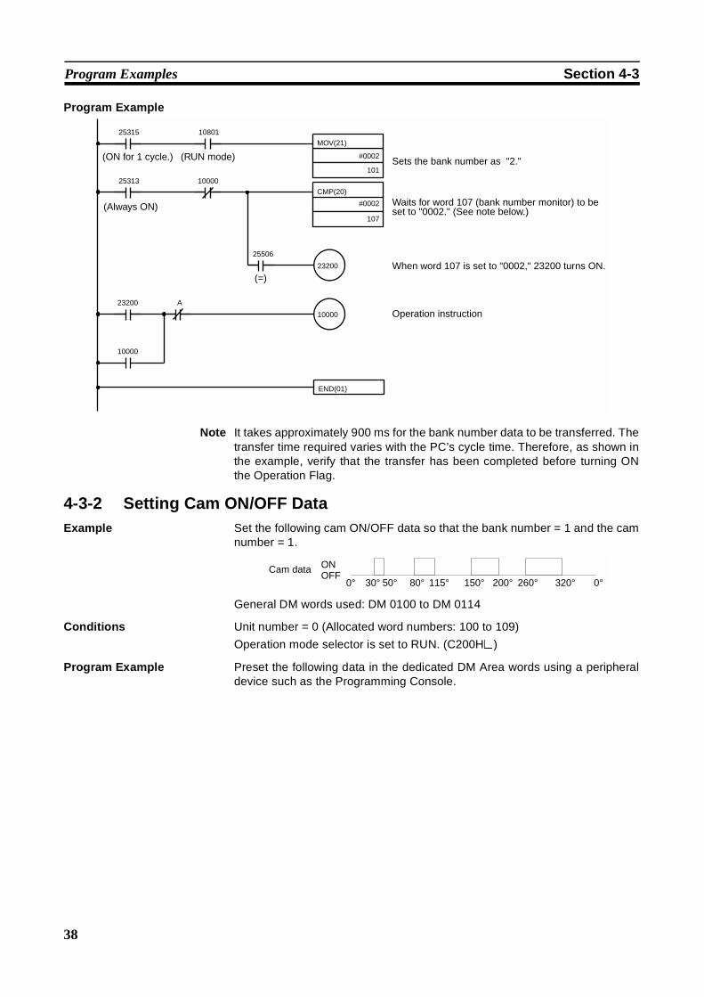
38
Program Examples Section 4-3
Program Example
Note It takes approximately 900 ms for the bank number data to be transferred. Thetransfer time required varies with the PC’s cycle time. Therefore, as shown inthe example, verify that the transfer has been completed before turning ONthe Operation Flag.
4-3-2 Setting Cam ON/OFF DataExample Set the following cam ON/OFF data so that the bank number = 1 and the cam
number = 1.
General DM words used: DM 0100 to DM 0114
Conditions Unit number = 0 (Allocated word numbers: 100 to 109)
Operation mode selector is set to RUN. (C200H@)
Program Example Preset the following data in the dedicated DM Area words using a peripheraldevice such as the Programming Console.
10000
MOV(21)
#0002
101
25315 10801
CMP(20)
#0002
107
25313 10000
23200
25506
23200 A
10000
END(01)
(ON for 1 cycle.) (RUN mode) Sets the bank number as "2."
(Always ON) Waits for word 107 (bank number monitor) to be set to "0002." (See note below.)
(=)When word 107 is set to "0002," 23200 turns ON.
Operation instruction
OFFONCam data
0°30° 50° 80° 115° 150° 200° 260° 320°0°
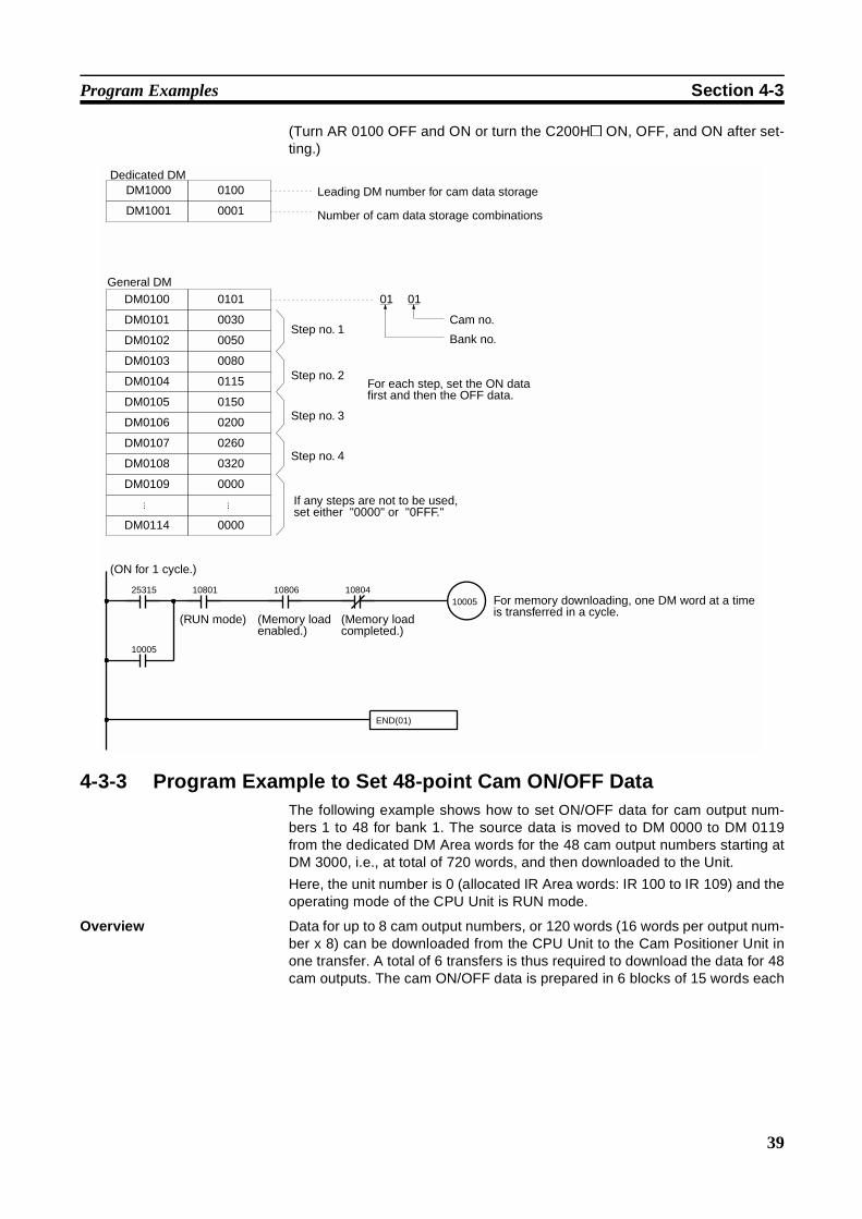
39
Program Examples Section 4-3
(Turn AR 0100 OFF and ON or turn the C200H@ ON, OFF, and ON after set-ting.)
4-3-3 Program Example to Set 48-point Cam ON/OFF DataThe following example shows how to set ON/OFF data for cam output num-bers 1 to 48 for bank 1. The source data is moved to DM 0000 to DM 0119from the dedicated DM Area words for the 48 cam output numbers starting atDM 3000, i.e., at total of 720 words, and then downloaded to the Unit.
Here, the unit number is 0 (allocated IR Area words: IR 100 to IR 109) and theoperating mode of the CPU Unit is RUN mode.
Overview Data for up to 8 cam output numbers, or 120 words (16 words per output num-ber x 8) can be downloaded from the CPU Unit to the Cam Positioner Unit inone transfer. A total of 6 transfers is thus required to download the data for 48cam outputs. The cam ON/OFF data is prepared in 6 blocks of 15 words each
DM1000
DM1001
0100
0001
DM0100
DM0101
0101
0030
DM0102 0050
DM0103 0080
DM0104 0115
DM0105 0150
DM0106 0200
DM0107 0260
DM0108 0320
DM0109 0000
...
DM0114 0000
01 01
Dedicated DMLeading DM number for cam data storage
General DM
Step no. 1
Step no. 2
Step no. 3
Step no. 4
Number of cam data storage combinations
Cam no.
Bank no.
For each step, set the ON data first and then the OFF data.
If any steps are not to be used, set either "0000" or "0FFF."
...
25315 10801 10806 1080410005
END(01)
10005
(ON for 1 cycle.)
(RUN mode) (Memory load enabled.)
(Memory load completed.)
For memory downloading, one DM word at a time is transferred in a cycle.

40
Program Examples Section 4-3
as shown below, the data in each block is copied in turn to normal DM Areawords and downloaded to the Cam Positioner Unit. The process must berepeated 6 times.
Initial Setup The following dedicated DM Area word data and the ON/OFF data for the 48cam outputs must be stored in advance using a Programming Console orother Programming Device. Do not store the cam ON/OFF data in normal DMArea words at this time. The data will be copied from the cam ON/OFF dataarea in sequence by the program for downloading.
• Set the address of the first word in the DM Area that will be used to holdthe cam ON/OFF data for downloading. Here, the address is DM 0000.
• Set the number of cam outputs that will be downloaded for each datatransfer. Here, the maximum number (8) is used.
SetDedicated DM Area words
Normal DM Area words
Work area 120 words(15 words x 8 cam outputs)
Download
Memory Download Flag (bit 05 of word n)
Cam Positioner Unit
XFER or other transfer instruction
Cam Data Area
Indirect addressing
(Used as storage pointer)
Cam output number
1 to 8 9 to 16 17 to 24 25 to 32 33 to 40 41 to 48
ON/OFF data for 48 cam outputs stored in advance. This data transferred 8 outputs (120 words) at a time to the same normal DM Area words.
1 2 3 4 5 6
Dedicated DM Area Words
DM 1000 0000 Address of first word to hold the cam data.
DM 1001 0008 Number of cam outputs that has been stored.(Number of cam outputs to be downloaded at once.
Normal DM Area Words
DM 0000 0000
to
DM 0119 0000
These 120 words are used to hold the cam data for 8 cam outputs at a time so that data for all 48 cam outputs can be downloaded in succession.
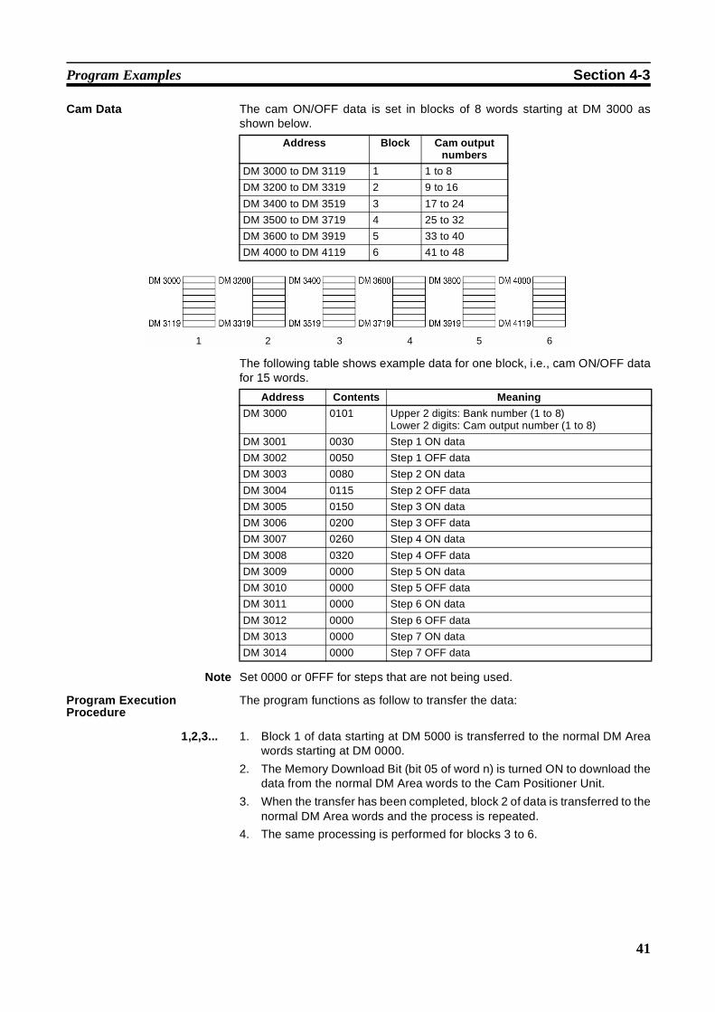
41
Program Examples Section 4-3
Cam Data The cam ON/OFF data is set in blocks of 8 words starting at DM 3000 asshown below.
The following table shows example data for one block, i.e., cam ON/OFF datafor 15 words.
Note Set 0000 or 0FFF for steps that are not being used.
Program ExecutionProcedure
The program functions as follow to transfer the data:
1,2,3... 1. Block 1 of data starting at DM 5000 is transferred to the normal DM Areawords starting at DM 0000.
2. The Memory Download Bit (bit 05 of word n) is turned ON to download thedata from the normal DM Area words to the Cam Positioner Unit.
3. When the transfer has been completed, block 2 of data is transferred to thenormal DM Area words and the process is repeated.
4. The same processing is performed for blocks 3 to 6.
Address Block Cam outputnumbers
DM 3000 to DM 3119 1 1 to 8
DM 3200 to DM 3319 2 9 to 16
DM 3400 to DM 3519 3 17 to 24
DM 3500 to DM 3719 4 25 to 32
DM 3600 to DM 3919 5 33 to 40
DM 4000 to DM 4119 6 41 to 48
1 2 3 4 5 6
Address Contents Meaning
DM 3000 0101 Upper 2 digits: Bank number (1 to 8)Lower 2 digits: Cam output number (1 to 8)
DM 3001 0030 Step 1 ON data
DM 3002 0050 Step 1 OFF data
DM 3003 0080 Step 2 ON data
DM 3004 0115 Step 2 OFF data
DM 3005 0150 Step 3 ON data
DM 3006 0200 Step 3 OFF data
DM 3007 0260 Step 4 ON data
DM 3008 0320 Step 4 OFF data
DM 3009 0000 Step 5 ON data
DM 3010 0000 Step 5 OFF data
DM 3011 0000 Step 6 ON data
DM 3012 0000 Step 6 OFF data
DM 3013 0000 Step 7 ON data
DM 3014 0000 Step 7 OFF data
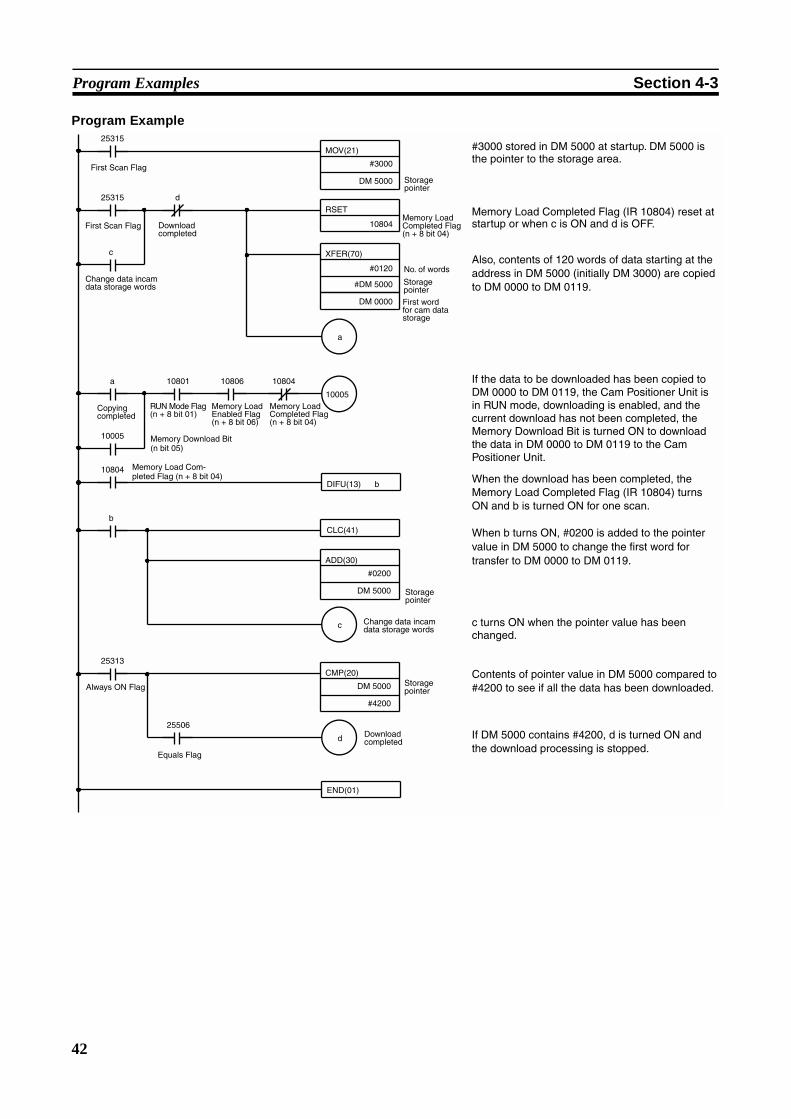
42
Program Examples Section 4-3
Program Example
25315
a
c
END(01)
d
25315
First Scan Flag
10005
10005
a 10801 10806 10804
DIFU(13) b
10804
CLC(41)
b
c
25313
d
25506
Memory Load Completed Flag (n + 8 bit 04)
Memory Load Enabled Flag (n + 8 bit 06)
RUN Mode Flag(n + 8 bit 01)
Memory Download Bit(n bit 05)
Memory Load Com-pleted Flag (n + 8 bit 04)
Always ON Flag
Equals Flag
First Scan Flag Download completed
Change data incam data storage words
Copying completed
Storage pointer
Memory Load Completed Flag (n + 8 bit 04)
No. of words
Storage pointer
First word for cam data storage
Storage pointer
Change data incam data storage words
Storage pointer
Download completed
Memory Load Completed Flag (IR 10804) reset at startup or when c is ON and d is OFF.
#3000 stored in DM 5000 at startup. DM 5000 is the pointer to the storage area.
If the data to be downloaded has been copied to DM 0000 to DM 0119, the Cam Positioner Unit is in RUN mode, downloading is enabled, and the current download has not been completed, the Memory Download Bit is turned ON to download the data in DM 0000 to DM 0119 to the Cam Positioner Unit.
Also, contents of 120 words of data starting at the address in DM 5000 (initially DM 3000) are copied to DM 0000 to DM 0119.
When b turns ON, #0200 is added to the pointer value in DM 5000 to change the first word for transfer to DM 0000 to DM 0119.
When the download has been completed, the Memory Load Completed Flag (IR 10804) turns ON and b is turned ON for one scan.
Contents of pointer value in DM 5000 compared to #4200 to see if all the data has been downloaded.
c turns ON when the pointer value has been changed.
If DM 5000 contains #4200, d is turned ON and the download processing is stopped.
MOV(21)
#3000
DM 5000
RSET
10804
XFER(70)
#0120
#DM 5000
DM 0000
ADD(30)
#0200
DM 5000
CMP(20)
DM 5000
#4200

43
Program Examples Section 4-3
4-3-4 Monitoring Cam ON/OFF DataExample Monitor the “bank number = 1” and the “cam number = 1” cam ON/OFF data.
The monitor data is stored in DM 0200 to DM 0214.
Conditions Unit number = 0 (Allocated word numbers: 100 to 109)
Operation mode selector is set to RUN. (C200H@)
Program Example Preset the following data, using a peripheral device such as the ProgrammingConsole.
(Turn AR 0100 OFF and ON or turn the C200H@ ON, OFF, and ON after set-ting.)
When memory uploading is complete, set the ON/OFF data.
DM1000
DM1001
0200
0001
Dedicated DM
Leading DM number for cam data storage
Number of cam data storage combinations
MOV(21)
#0101
DM0200
25315 10801 10806
25315 10801 10806 10804
10004
END(01)
10004
#01 01
(ON for 1 cycle.) (RUN mode) (Memory load enabled.)
Cam no.
Bank no.
(RUN mode) (Memory load enabled.)
(Memory load completed.)
For memory uploading, one DM word of data is retrieved in a cycle.
For words with no cam data, "0FFF" is stored.
DM0201 0030
DM0202 0050
DM0203 0080
DM0204 0115
DM0205 0150
DM0206 0200
DM0207 0260
DM0208 0320
DM0209 0FFF
...
DM0214 0FFF
Step no. 1
Step no. 2
Step no. 3
Step no. 4
For each step, set the ON data first and then the OFF data.
...
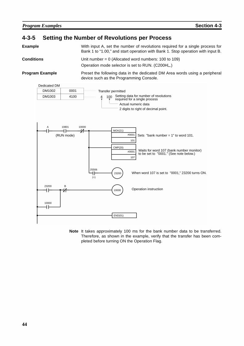
44
Program Examples Section 4-3
4-3-5 Setting the Number of Revolutions per ProcessExample With input A, set the number of revolutions required for a single process for
Bank 1 to “1.00,” and start operation with Bank 1. Stop operation with input B.
Conditions Unit number = 0 (Allocated word numbers: 100 to 109)
Operation mode selector is set to RUN. (C200H@)
Program Example Preset the following data in the dedicated DM Area words using a peripheraldevice such as the Programming Console.
Note It takes approximately 100 ms for the bank number data to be transferred.Therefore, as shown in the example, verify that the transfer has been com-pleted before turning ON the Operation Flag.
10000
MOV(21)
#0001
101
A 10801
CMP(20)
#0001
107
2320025506
(=)
23200 B
10000
END(01)
10000
DM1002
DM1003
0001
4100 4 100
Dedicated DM
Transfer permittedSetting data for number of revolutions required for a single process
Actual numeric data2 digits to right of decimal point.
(RUN mode) Sets "bank number = 1" to word 101.
Waits for word 107 (bank number monitor) to be set to "0001." (See note below.)
When word 107 is set to "0001," 23200 turns ON.
Operation instruction

45
SECTION 5Troubleshooting
This section provides possible errors and corrections.
Error Detection . . . . . . . . . . . . . . . . . . . . . . . . . . . . . . . . . . . . . . . . . . . . . . . . 46
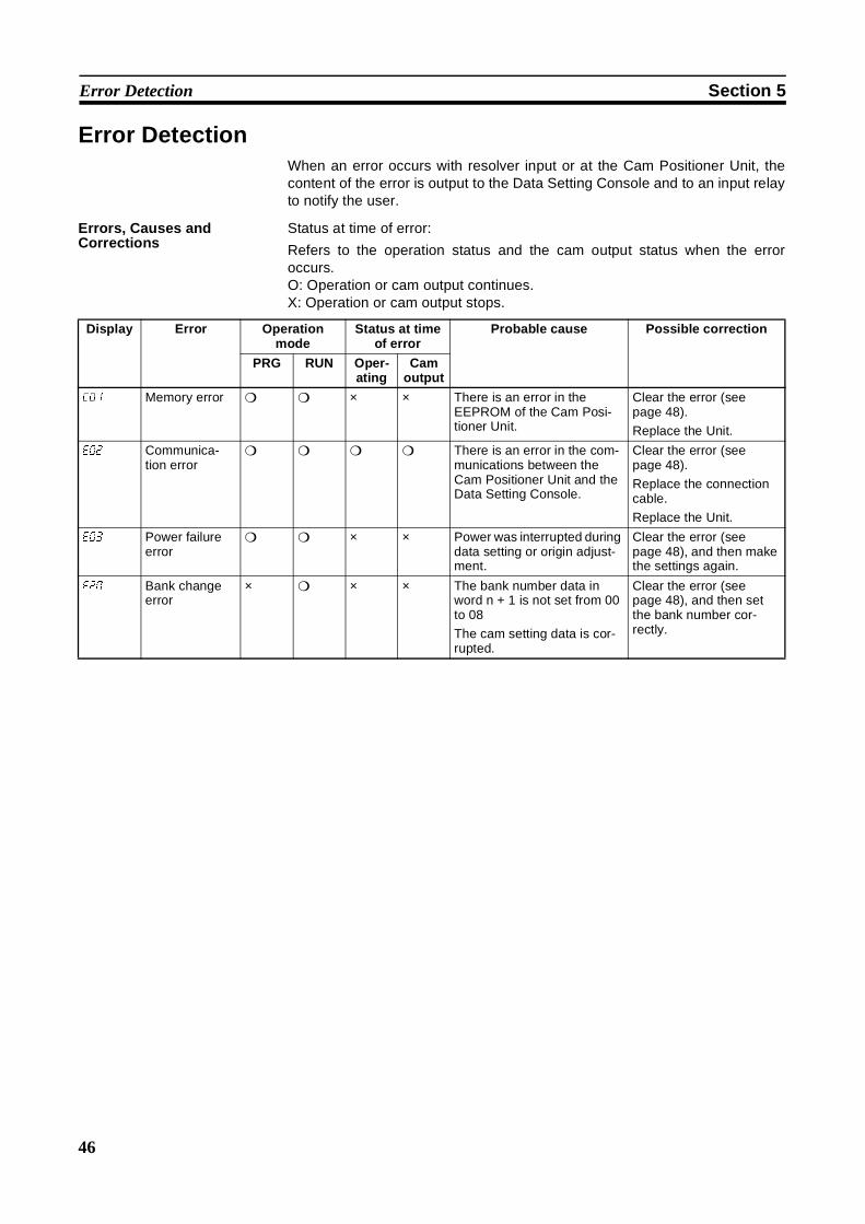
46
Error Detection Section 5
Error DetectionWhen an error occurs with resolver input or at the Cam Positioner Unit, thecontent of the error is output to the Data Setting Console and to an input relayto notify the user.
Errors, Causes andCorrections
Status at time of error:
Refers to the operation status and the cam output status when the erroroccurs.O: Operation or cam output continues.X: Operation or cam output stops.
Display Error Operationmode
Status at timeof error
Probable cause Possible correction
PRG RUN Oper-ating
Camoutput
e01 Memory error × × There is an error in theEEPROM of the Cam Posi-tioner Unit.
Clear the error (seepage 48).
Replace the Unit.
e02 Communica-tion error
There is an error in the com-munications between theCam Positioner Unit and theData Setting Console.
Clear the error (seepage 48).
Replace the connectioncable.
Replace the Unit.
e03 Power failureerror
× × Power was interrupted duringdata setting or origin adjust-ment.
Clear the error (seepage 48), and then makethe settings again.
e20 Bank changeerror
× × × The bank number data inword n + 1 is not set from 00to 08
The cam setting data is cor-rupted.
Clear the error (seepage 48), and then setthe bank number cor-rectly.

47
Error Detection Section 5
Note 1. Display:Refers to the display on the Data Setting Console.
2. Operation mode:Refers to the setting of the operation mode selector when the error occurs.If there is a circle in both the PRG and RUN columns, it indicates that theerror applies to both modes. A triangle for the resolver disconnection errorindicates that the error applies only in PRG mode and when the power isturned on.
e21 Data transfererror
The cam data is not set from000 to 359 or 0FFF.
The data for setting thenumber of revolutionsrequired for a single cycle isoutside of the allowablerange.
The decimal point positiondata is other than 1, 2, or 4.
The numeric data is not inBCD.
The memory upload andmemory download pointswere turned ONsimultaneously.
The Data Setting Consolewas operated during datatransmission.
Data transfer was executedduring Data Setting Consoleoperation.
The transfer bank numberwas not from 1 to 8 or thetransfer cam number was not1 to 48.
The transfer of the requirednumber of revolutions for asingle process (i.e., bankselection) was executedwhile the display on the DataSetting Console wasflashing.
Clear the error (seepage 48), and then checkthe probable causeslisted on the left. Correctthe problem and executethe transfer again.
e22 Parametererror
The DM m and DM m + 1 setvalues are not correct. 0999is exceeded in the generalDM area.
Correct the set values inDM m and DM m + 1, andthen clear the error andtry again.
e10 Resolverdisconnectionerror
∆ (seenote 2)
× × The resolver connectioncable is faulty.
Replace the resolverconnection cable.
Display Error Operationmode
Status at timeof error
Probable cause Possible correction
PRG RUN Oper-ating
Camoutput
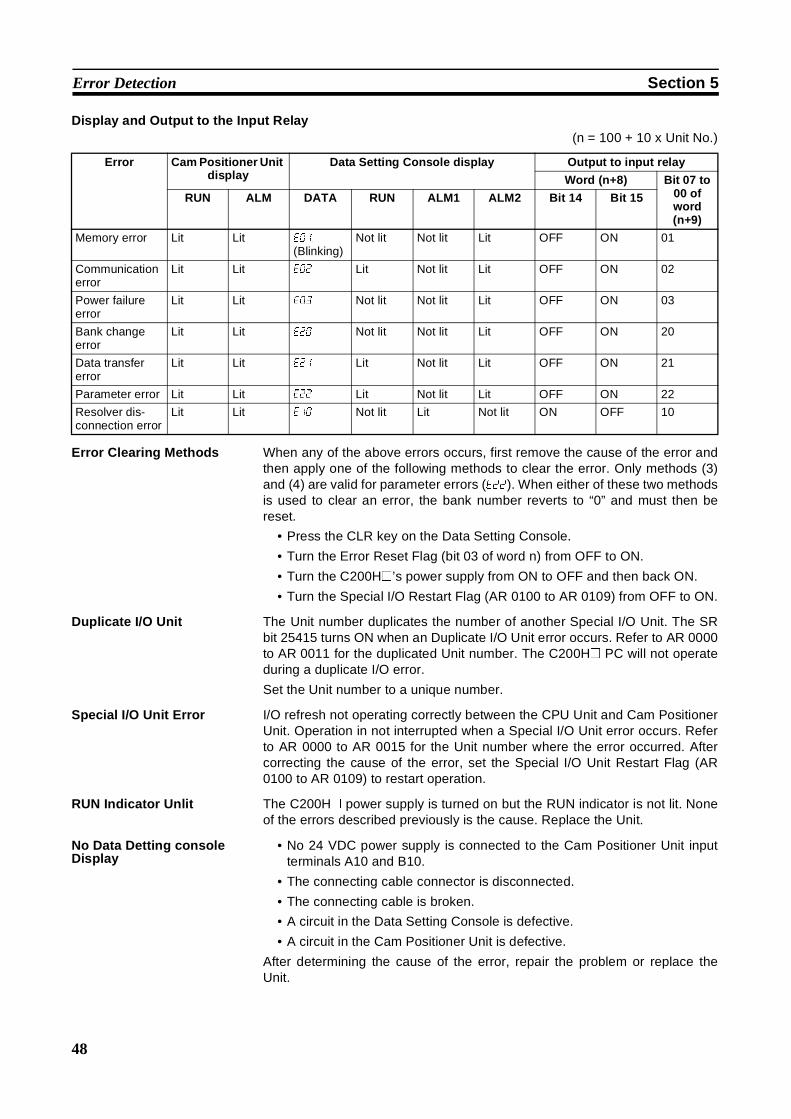
48
Error Detection Section 5
Display and Output to the Input Relay(n = 100 + 10 x Unit No.)
Error Clearing Methods When any of the above errors occurs, first remove the cause of the error andthen apply one of the following methods to clear the error. Only methods (3)and (4) are valid for parameter errors (e22). When either of these two methodsis used to clear an error, the bank number reverts to “0” and must then bereset.
• Press the CLR key on the Data Setting Console.
• Turn the Error Reset Flag (bit 03 of word n) from OFF to ON.
• Turn the C200H@’s power supply from ON to OFF and then back ON.
• Turn the Special I/O Restart Flag (AR 0100 to AR 0109) from OFF to ON.
Duplicate I/O Unit The Unit number duplicates the number of another Special I/O Unit. The SRbit 25415 turns ON when an Duplicate I/O Unit error occurs. Refer to AR 0000to AR 0011 for the duplicated Unit number. The C200H@ PC will not operateduring a duplicate I/O error.
Set the Unit number to a unique number.
Special I/O Unit Error I/O refresh not operating correctly between the CPU Unit and Cam PositionerUnit. Operation in not interrupted when a Special I/O Unit error occurs. Referto AR 0000 to AR 0015 for the Unit number where the error occurred. Aftercorrecting the cause of the error, set the Special I/O Unit Restart Flag (AR0100 to AR 0109) to restart operation.
RUN Indicator Unlit The C200H@ power supply is turned on but the RUN indicator is not lit. Noneof the errors described previously is the cause. Replace the Unit.
No Data Detting consoleDisplay
• No 24 VDC power supply is connected to the Cam Positioner Unit inputterminals A10 and B10.
• The connecting cable connector is disconnected.
• The connecting cable is broken.
• A circuit in the Data Setting Console is defective.
• A circuit in the Cam Positioner Unit is defective.
After determining the cause of the error, repair the problem or replace theUnit.
Error Cam Positioner Unitdisplay
Data Setting Console display Output to input relay
Word (n+8) Bit 07 to00 ofword(n+9)
RUN ALM DATA RUN ALM1 ALM2 Bit 14 Bit 15
Memory error Lit Lit e01
(Blinking)Not lit Not lit Lit OFF ON 01
Communicationerror
Lit Lit e02 Lit Not lit Lit OFF ON 02
Power failureerror
Lit Lit e03 Not lit Not lit Lit OFF ON 03
Bank changeerror
Lit Lit e20 Not lit Not lit Lit OFF ON 20
Data transfererror
Lit Lit e21 Lit Not lit Lit OFF ON 21
Parameter error Lit Lit e22 Lit Not lit Lit OFF ON 22
Resolver dis-connection error
Lit Lit e10 Not lit Lit Not lit ON OFF 10
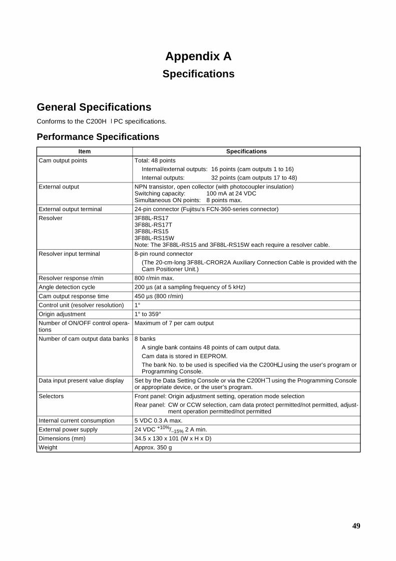
49
Appendix ASpecifications
General SpecificationsConforms to the C200H@ PC specifications.
Performance SpecificationsItem Specifications
Cam output points Total: 48 points
Internal/external outputs: 16 points (cam outputs 1 to 16)
Internal outputs: 32 points (cam outputs 17 to 48)
External output NPN transistor, open collector (with photocoupler insulation)Switching capacity: 100 mA at 24 VDCSimultaneous ON points: 8 points max.
External output terminal 24-pin connector (Fujitsu’s FCN-360-series connector)
Resolver 3F88L-RS173F88L-RS17T3F88L-RS153F88L-RS15WNote: The 3F88L-RS15 and 3F88L-RS15W each require a resolver cable.
Resolver input terminal 8-pin round connector
(The 20-cm-long 3F88L-CROR2A Auxiliary Connection Cable is provided with theCam Positioner Unit.)
Resolver response r/min 800 r/min max.
Angle detection cycle 200 µs (at a sampling frequency of 5 kHz)
Cam output response time 450 µs (800 r/min)
Control unit (resolver resolution) 1°Origin adjustment 1° to 359°Number of ON/OFF control opera-tions
Maximum of 7 per cam output
Number of cam output data banks 8 banks
A single bank contains 48 points of cam output data.
Cam data is stored in EEPROM.
The bank No. to be used is specified via the C200H@ using the user’s program orProgramming Console.
Data input present value display Set by the Data Setting Console or via the C200H@ using the Programming Consoleor appropriate device, or the user’s program.
Selectors Front panel: Origin adjustment setting, operation mode selection
Rear panel: CW or CCW selection, cam data protect permitted/not permitted, adjust-ment operation permitted/not permitted
Internal current consumption 5 VDC 0.3 A max.
External power supply 24 VDC +10%/–15% 2 A min.
Dimensions (mm) 34.5 x 130 x 101 (W x H x D)
Weight Approx. 350 g

50
Specifications Appendix A
Output Specifications
Note The ON and OFF response times are numbers that depend on the hardware and are not times that canbe controlled by software.
Item Specifications
Switching capacity 24 VDC 100 mA
Leakage current 160 µA max.
Residual voltage 1.8 V max.
ON response time 20 µs max. (see note)
OFF response time 20 µs max. (see note)
Number of circuits 16 pts./common, 1 circuit
Simultaneous ON points 8 points
External power supply 24 VDC at 2 A max. (including load)
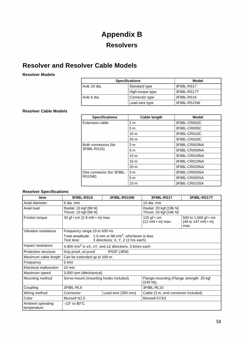
51
Appendix BResolvers
Resolver and Resolver Cable ModelsResolver Models
Resolver Cable Models
Resolver Specifications
Specifications Model
Axle 10 dia. Standard type 3F88L-RS17
High-torque type 3F88L-RS17T
Axle 6 dia. Connector type 3F88L-RS15
Lead-wire type 3F88L-RS15W
Specifications Cable length Model
Extension cable 2 m 3F88L-CR002C
5 m 3F88L-CR005C
10 m 3F88L-CR010C
20 m 3F88L-CR020C
Both connectors (for3F88L-RS15)
3 m 3F88L-CR003NA
5 m 3F88L-CR005NA
10 m 3F88L-CR010NA
15 m 3F88L-CR015NA
20 m 3F88L-CR020NA
One connector (for 3F88L-RS15W)
3 m 3F88L-CR003SA
5 m 3F88L-CR005SA
10 m 3F88L-CR010SA
Item 3F88L-RS15 3F88L-RS15W 3F88L-RS17 3F88L-RS17TAxial diameter 6 dia. mm 10 dia. mm
Axial load Radial: 10 kgf 98 NThrust: 10 kgf 98 N
Radial: 20 kgf 196 NThrust: 20 kgf 196 N
Friction torque 30 gf • cm 2.9 mN • m max. 120 gf • cm12 mN • m max.
500 to 1,500 gf • cm49 to 147 mN • mmax.
Vibration resistance Frequency range:10 to 500 HzTotal amplitude: 1.5 mm or 98 m/s2, whichever is lessTest time: 3 directions: X, Y, Z (2 hrs each)
Impact resistance 4,900 m/s2 in ±X, ±Y, and ±Z directions, 3 times each
Protective structure Drip proof, oil proof IP52F (JEM)
Maximum cable length Can be extended up to 100 m.
Frequency 5 kHz
Electrical malfunction 10 min
Maximum speed 3,000 rpm (Mechanical)
Mounting method Servo-mount (mounting hooks included) Flange-mounting (Flange strength: 25 kgf245 N)
Coupling 3F88L-RL6 3F88L-RL10
Wiring method Connector Lead wire (350 mm) Cable (3 m, end connector included)
Color Munsell N1.5 Munsell 5Y3/1
Ambient operatingtemperature
–10° to 80°C
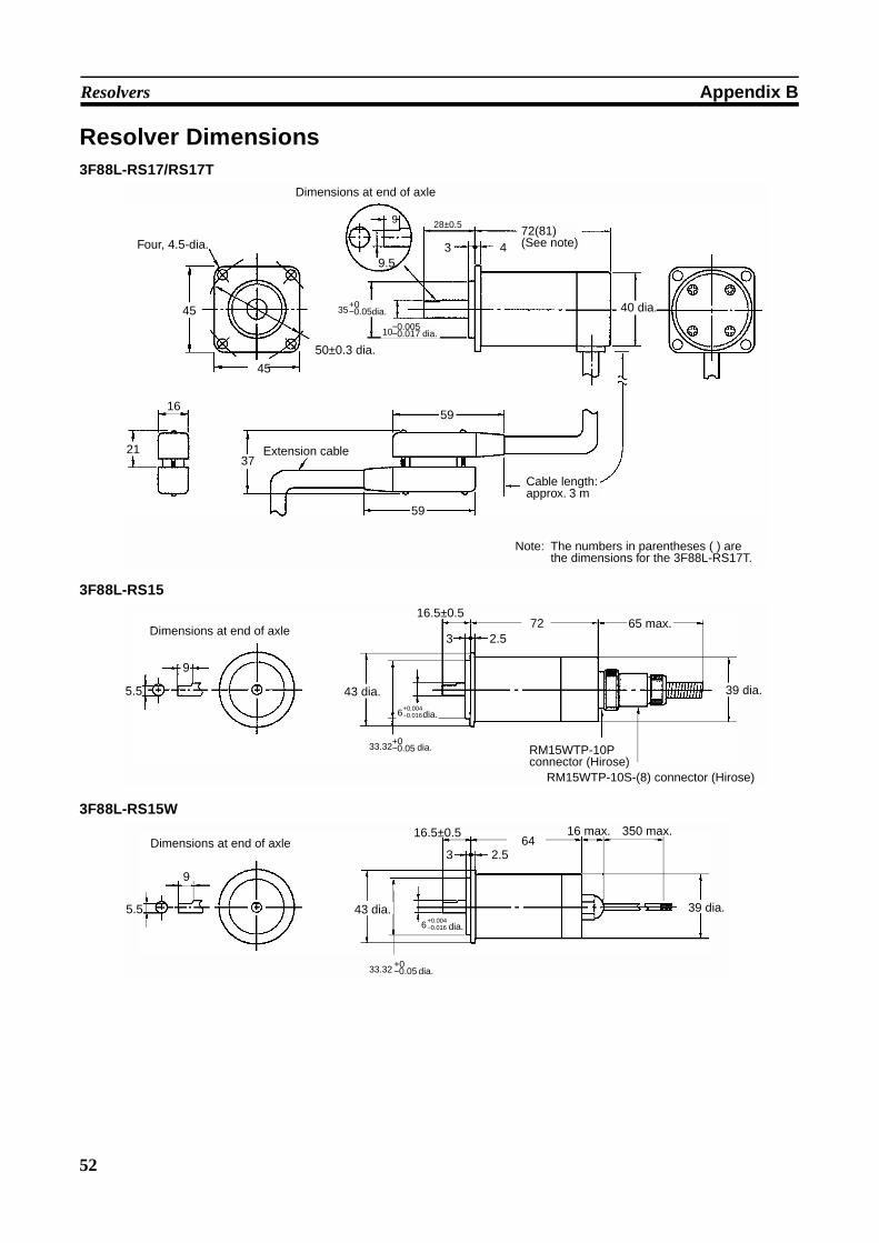
52
Resolvers Appendix B
Resolver Dimensions3F88L-RS17/RS17T
3F88L-RS15
3F88L-RS15W
10−0.005−0.017 dia.
37
3 49.5
9
21
16
45
45
Four, 4.5-dia.
50±0.3 dia.
Dimensions at end of axle
Extension cable
Cable length: approx. 3 m
72(81) (See note)
28±0.5
Note: The numbers in parentheses ( ) are the dimensions for the 3F88L-RS17T.
59
40 dia.
59
35+0−0.05dia.
16.5±0.5
33.32+0−0.05 dia.
6+0.004−0.016dia.
Dimensions at end of axle
5.5
9
3 2.572
39 dia.43 dia.
RM15WTP-10P connector (Hirose)
RM15WTP-10S-(8) connector (Hirose)
65 max.
6+0.004−0.016 dia.
39 dia.
350 max.Dimensions at end of axle
9
5.5
642.53
16 max.
43 dia.
16.5±0.5
33.32 +0−0.05 dia.
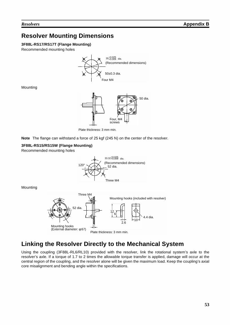
53
Resolvers Appendix B
Resolver Mounting Dimensions3F88L-RS17/RS17T (Flange Mounting)Recommended mounting holes
Mounting
Note The flange can withstand a force of 25 kgf (245 N) on the center of the resolver.
3F88L-RS15/RS15W (Flange Mounting)Recommended mounting holes
Mounting
Linking the Resolver Directly to the Mechanical SystemUsing the coupling (3F88L-RL6/RL10) provided with the resolver, link the rotational system’s axle to theresolver’s axle. If a torque of 1.7 to 2 times the allowable torque transfer is applied, damage will occur at thecentral region of the coupling, and the resolver alone will be given the maximum load. Keep the coupling’s axialcore misalignment and bending angle within the specifications.
(Recommended dimensions)
50±0.3 dia.
Four M4
35+0.025+0.009 dia.
Plate thickness: 3 mm min.
Four, M4 screws
50 dia.
(Recommended dimensions)52 dia.
Three M4
120°
33.32+0.025+0.009 dia.
Plate thickness: 3 mm min.
Three M4
52 dia.
4.4 dia.
Mounting hooks (External diameter: φ:67)
Mounting hooks (included with resolver)
126
2.610
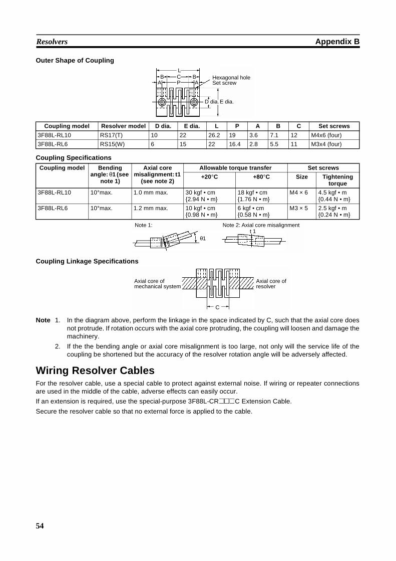
54
Resolvers Appendix B
Outer Shape of Coupling
Coupling Specifications
Coupling Linkage Specifications
Note 1. In the diagram above, perform the linkage in the space indicated by C, such that the axial core doesnot protrude. If rotation occurs with the axial core protruding, the coupling will loosen and damage themachinery.
2. If the the bending angle or axial core misalignment is too large, not only will the service life of thecoupling be shortened but the accuracy of the resolver rotation angle will be adversely affected.
Wiring Resolver CablesFor the resolver cable, use a special cable to protect against external noise. If wiring or repeater connectionsare used in the middle of the cable, adverse effects can easily occur.
If an extension is required, use the special-purpose 3F88L-CR@@@C Extension Cable.
Secure the resolver cable so that no external force is applied to the cable.
LB C B
PA A
E dia.D dia.
Hexagonal hole Set screw
Coupling model Resolver model D dia. E dia. L P A B C Set screws
3F88L-RL10 RS17(T) 10 22 26.2 19 3.6 7.1 12 M4x6 (four)
3F88L-RL6 RS15(W) 6 15 22 16.4 2.8 5.5 11 M3x4 (four)
Coupling model Bendingangle: θ1 (see
note 1)
Axial coremisalignment: t1
(see note 2)
Allowable torque transfer Set screws
+20°C +80°C Size Tighteningtorque
3F88L-RL10 10°max. 1.0 mm max. 30 kgf • cm2.94 N • m
18 kgf • cm1.76 N • m
M4 × 6 4.5 kgf • m0.44 N • m
3F88L-RL6 10°max. 1.2 mm max. 10 kgf • cm0.98 N • m
6 kgf • cm0.58 N • m
M3 × 5 2.5 kgf • m0.24 N • m
θ1
Note 2: Axial core misalignmentt 1
Note 1:
Axial core of resolver
Axial core of mechanical system
C
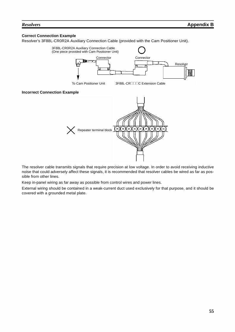
55
Resolvers Appendix B
Correct Connection ExampleResolver’s 3F88L-CR0R2A Auxiliary Connection Cable (provided with the Cam Positioner Unit).
Incorrect Connection Example
The resolver cable transmits signals that require precision at low voltage. In order to avoid receiving inductivenoise that could adversely affect these signals, it is recommended that resolver cables be wired as far as pos-sible from other lines.
Keep in-panel wiring as far away as possible from control wires and power lines.
External wiring should be contained in a weak-current duct used exclusively for that purpose, and it should becovered with a grounded metal plate.
3F88L-CR0R2A Auxiliary Connection Cable (One piece provided with Cam Positioner Unit)
Connector
Resolver
To Cam Positioner Unit 3F88L-CR@@@C Extension Cable
Connector
Repeater terminal block
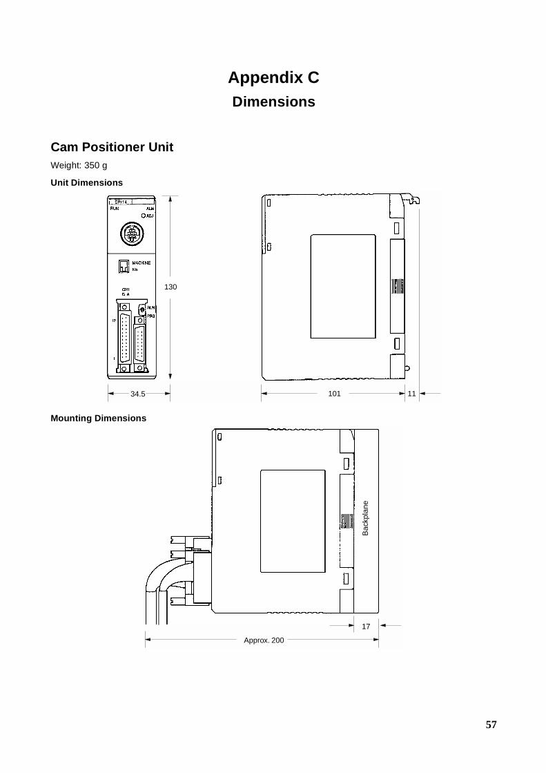
57
Appendix CDimensions
Cam Positioner UnitWeight: 350 g
Unit Dimensions
Mounting Dimensions
130
101 1134.5
Approx. 200
17
Bac
kpla
ne
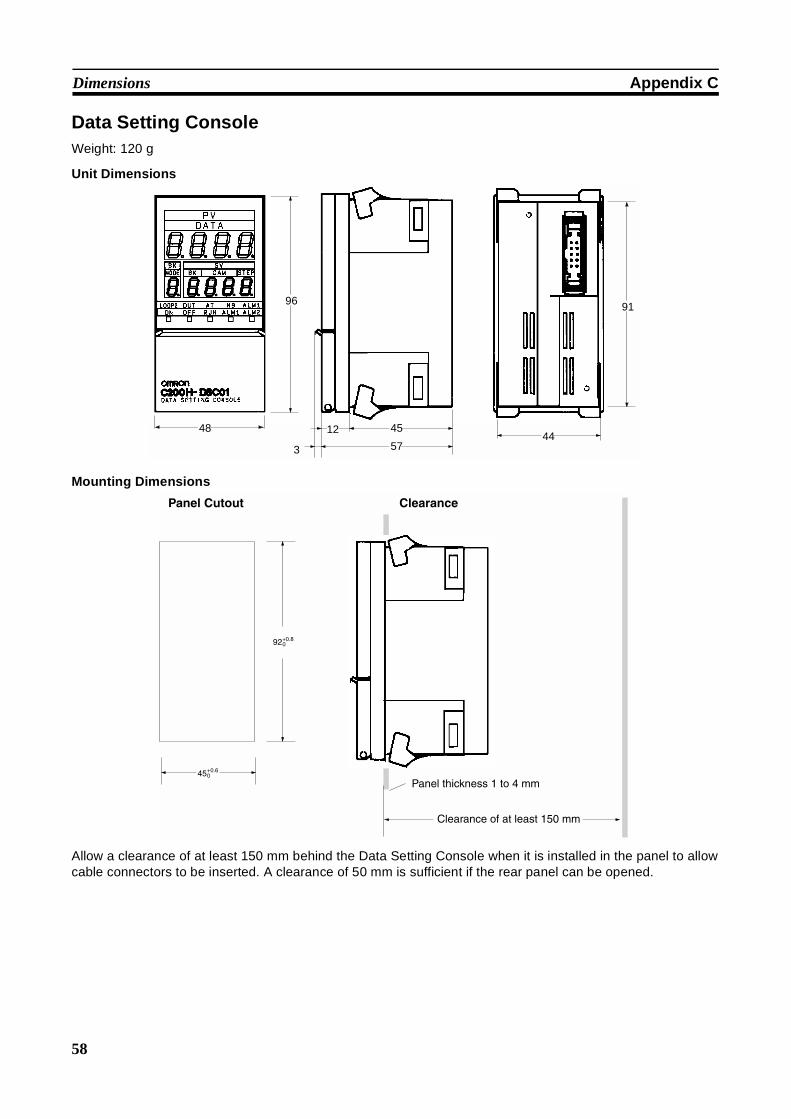
58
Dimensions Appendix C
Data Setting ConsoleWeight: 120 g
Unit Dimensions
Mounting Dimensions
Allow a clearance of at least 150 mm behind the Data Setting Console when it is installed in the panel to allowcable connectors to be inserted. A clearance of 50 mm is sufficient if the rear panel can be opened.
48
3
45
5744
91
12
96
Panel Cutout Clearance
92+0.80
45+0.60
Panel thickness 1 to 4 mm
Clearance of at least 150 mm
59
Index
Bbank number
setting program, 37
bit allocationdata contents, 27
BK (BANKS)See also display functions
CCAM
See also display functions
camoutput data, 49output points, 49setting data and outputs, 18
cam ON/OFF datamonitoring, 43programming, 38retrieving procedures, 36setting operations, 33
DDATA
See also display functions
datainput present value display, 49modes
See also modes
monitoring, 18setting, 17setting for peripheral devices, 32
data contentsdedicated DM, 32general DM, 32
Data MemoryDM number allocation, 26General DM, 31Read Only data, 31
Data Setting Consolefunctions, 16nomenclature, 15operating procedures, 14
display functionsBK, 16CAM, 16DATA, 16MODE, 16STEP, 16
Eerror codes, 30
errorscauses and corrections, 46clearing, 48data setting console display, 48indicators, 48
F–Kfeatures, 2
I\O unitduplicate error, 48
internal power consumption, 49
keyboard functions, 17
Mmemory
bit allocation, 27number allocation, 26word allocations, 26
MODESee also display functions
modesadjustment operation, 23data setting procedure, 19monitoring cam angle, 23monitoring process execution cycles, 22protect setting, 20selection, 19setting process revolutions, 21
mounting racksmaximum Units, 4
N–Onomenclature and functions, 6
ON/OFF controloperating specifications, 49
operation displays, 16
origin adjustment, 24, 33, 49
outputsexternal, 49
Pperipheral devices
data setting, 32operations, 32origin adjustment, 33retrieving cam ON/OFF data, 35setting bank number, 33
60
Index
startup operation, 33
power supplyexternal, 49
precautionsapplications, xiiigeneral, xiioperating environment, xiisafety, xii
programmingmonitoring cam ON/OFF data, 43setting bank number, 37setting cam ON/OFF data, 38
Rresolver
cable models, 51connecting, 11models, 51specifications, 49
Sselectors
specifications, 49
single processsetting number of revolutions, 36
Slave Rackmounting parameters, 4
Special I/O Unitsmaximum on Slave rack, 4
specifications, 49
STEPSee also display functions
switch settingsDIP switch, 8operation mode selection, 7origin adjustment switch, 8unit number, 7
system configuration, 3
UUnit
dimensions, 49, 57mounting dimensions, 57weight, 49
Wwiring
connecting, 10connecting resolver, 11Data Setting Console, 12external cam output, 8precautions, 12preventing noise, 10recommended cables, 9
61
Revision History
A manual revision code appears as a suffix to the catalog number on the front cover of the manual.
The following table outlines the changes made to the manual during each revision. Page numbers refer to theprevious version.
Revision code Date Revised content
1 September 1993 Original production
1A July 1995 Page 48: The maximum speed in Resolver Specifications corrected from300 rpm to 3,000 rpm.
2 January 2001 PLP section added to the front of the manual.“C200H” changed to “C200H@” where appropriate to indicate the applicablePCs.Pages 2, 16, 17, 27, 28 and 45: “External outputs” changed to “internal/externaloutputs.”Page 8: Note added.Pages 22, 28: “Per unit time” changed to “per minute.”Page 28: Information added to description for n+6.Page 33: “Bit 05” corrected to “bit 04” and “bit 07” corrected to “bit 06.”Page 34: “Bit 07” corrected to “bit 06.”Page 35: Information added to step 2 in the middle of the page.Page 37: Section added.Pages 37 and 38: “Dedicated DM Area words” added.
Page 48: G’s changed to m/s2.
Cat. No. W224-E1-2
Revision code