c2-2007 national electrical safety code - ee batchzero...
TRANSCRIPT

NationalElectricalSafetyCode®
C2-2007
®
3 Park Avenue, New York, NY 10016-5997, USA

AccreditedStandardsCommittee
C2-2007
National Electrical Safety Code®
SecretariatInstitute of Electrical and Electronics Engineers, Inc.
Approved 20 April 2006Institute of Electrical and Electronics Engineers, Inc.
Approved 16 June 2006American National Standards Institute
2007 Edition
Abstract: This standard covers basic provisions for safeguarding of persons from hazards arising from theinstallation, operation, or maintenance of (1) conductors and equipment in electric supply stations, and(2) overhead and underground electric supply and communication lines. It also includes work rules for theconstruction, maintenance, and operation of electric supply and communication lines and equipment. Thestandard is applicable to the systems and equipment operated by utilities, or similar systems and equipment,of an industrial establishment or complex under the control of qualified persons. This standard consists of theintroduction, definitions, grounding rules, list of referenced and bibliographic documents, and Parts 1, 2, 3,and 4 of the 2007 Edition of the National Electrical Safety Code.
Keywords: communications industry safety; construction of communication lines; construction of electricsupply lines; electrical safety; electric supply stations; electric utility stations; high-voltage safety; operation ofcommunications systems; operation of electric supply systems; power station equipment; power stationsafety; public utility safety; safety work rules; underground communication line safety; underground electricline safety
1 August 2006 SH95514
The Institute of Electrical and Electronics Engineers, Inc.3 Park Avenue, New York, NY 10016-5997, USA
Copyright © 2006 by the Institute of Electrical and Electronics Engineers, Inc.
All rights reserved. Published 2006Printed in the United States of America
National Electrical Safety Code and NESC are registered trademarks and service marks in the U.S. Patent & Trademark Office, owned by The Institute of Electrical and Electronics Engineers, Incorporated.
The NESC logo is a trademark in the U.S. Patent & Trademark Office, owned by The Institute of Electrical and Electronics Engineers, Incorporated.
National Electrical Code and NEC are registered trademarks in the U.S. Patent & Trademark Office, owned by the National Fire Protection Association.
ISBN 0-7381-4893-8
Public authorities are granted permission to republish the materialherein in laws, regulations, administrative orders, ordinances, or
similar documents. No other party may reproduce in any form, in anelectronic retrieval system or otherwise, any portion of this document,
without the prior written permission of the publisher.

Recognized as an American National Standard
An American National Standard implies a consensus of those substantially concerned with its scope andprovisions. An American National Standard is intended as a guide to aid the manufacturer, the consumer,and the general public. The existence of an American National Standard does not in any respect precludeanyone, whether he has approved the standard or not, from manufacturing, marketing, purchasing, orusing products, processes, or procedures not conforming to the standard. American National Standardsare subject to periodic review and users are cautioned to obtain the latest editions.

Foreword
This publication consists of the parts of the National Electrical Safety Code® (NESC®) currently in effect.The former practice of designating parts by editions has not been practical for some time. In the 1977Edition, Parts 1 and 4 were 6th editions; Part 2 was a 7th edition; Part 3 was a revision of the 6th edition;Part 2, Section 29, did not cover the same subject matter as the 5th edition; and Part 3 was withdrawn in1970. In the 1987 Edition, revisions were made in all parts, and revisions to all parts have been made insubsequent editions. It is therefore recommended that reference to the NESC be made solely by the year ofthe published volume and desired part number. Separate copies of the individual parts are not available.
Work on the NESC started in 1913 at the National Bureau of Standards (NBS), resulting in the publicationof NBS Circular 49. The last complete edition of the Code (the 5th edition, NBS Handbook H30) was issuedin 1948, although separate portions had been available at various times starting in 1938. Part 2—Definitions,and the Grounding Rules, 6th edition, was issued as NBS Handbook H81, ANSI C2.2-1960, in November1961, but work on other parts was not actively in process again until 1970.
In 1970 the C2 Committee decided to delete the Rules for the Installation and Maintenance of ElectricUtilization Equipment (Part 3 of the 5th edition), now largely covered by the National Electrical Code®
(NEC®)(NFPA 70, 2005 Edition), and the Rules for Radio Installation (Part 5 of the 5th edition) from futureeditions. The Discussion of the NESC, issued as NBS Handbook H4 (1928 Edition) for the 4th edition of theNESC and as NBS Handbook H39 for Part 2 of the Grounding Rules of the 5th edition, was not publishedfor the 6th edition.
The 1981 Edition included major changes in Parts 1, 2, and 3, minor changes in Part 4, and the incorporationof the rules common to all parts into Section 1. The 1984 Edition was revised to update all references and tolist those references in a new Section 3. Converted metric values, for information only, were added. Gender-related terminology was deleted. Section 1—Introduction, Section 2—Definitions, Section 3—References,and Section 9—Grounding Methods, were made applicable to each of the Parts 1, 2, 3, and 4.
The 1987 Edition was revised extensively. Definitions were changed or added. Requirements affectinggrounding methods, electric supply stations, overhead line clearances and loading, underground lines, andwork rules were revised.
The 1990 Edition included several major changes. General rules were revised. A significant change to themethod for specifying overhead line clearances was made and the rationale added as Appendix A.Requirements for clearances of overhead lines from grain bins and an alternate method for determining thestrength requirements for wood structures was added. Rules covering grounding methods, electric supplystations, underground lines, and work rules were changed.
In the 1993 Edition, changes were made in the rules applicable to emergency and temporary installations. InSection 9 and Parts 1, 2, and 3, rules were extended or clarified to include HVDC systems. The requirementsfor random separation of direct-buried supply and communications systems were modified for consistencyand clarity, as was the rule in Part 4 on tagging electric supply circuits.
In the 1997 Edition, the most notable general change that took place is that numerical values in the metric(SI) system are shown in the preferred position, with customary inch-foot-pound values (inside parentheses)following. A bibliography, Appendix B, which consists of a list of resources identified in notes orrecommendations, was added. Changes were made to rules affecting grounding, electric supply stations, andoverhead lines, particularly with regard to clearance rules applicable to emergency and temporaryinstallations. Strength requirements contained in Sections 24, 25, and 26 were revised completely.
This foreword is not a part of Accredited Standards Committee C2-2007, National Electrical Safety Code.
Copyright © 2006 IEEE. All rights reserved. iii
Underground line requirements for random separation for underground lines of direct-buried cables weremodified. The requirement for cable identification marking by means of sequentially placed logos wasintroduced. Work rules added a requirement that warning signs and tags comply with applicable ANSIstandards, tagging requirements were clarified with regard to SCADA, and extensive requirements for fallprotection were added.
In the 2002 Edition, several changes were made that affected all or several parts of the Code. Particularly,this edition clarifies interfaces between the NEC and NESC with regard to Code jurisdiction in the area ofstreet lights and area lights. Also included is clarification for situations between utility workers and theirauthorized contractors and installations on industrial complexes.
The major revisions for the 2007 Edition include grounding, moving sag calculations to Section 23, movingguy and span wires insulator rules to Section 21, phasing out of the alternate method for load factors andstrength factors, flammable materials transported, phase-to-phase cover-up, and minimum approachdistance tables.
Subcommittee 1 concerned itself with assuring continuity between subcommittees and supervising theaddition of definitions and references. Definitions included work on ducts, conduits, conduit systemsraceways, overvoltage/transient conditions, shield wires/static wires, flashover/sparkover, sag, creep, readilyclimbable/not readily climbable, and others. Inspection and work rules as related to Rule 13 were clarified.The extensive changes made by Working Group 4.10 on overhead clearances was reviewed and accepted forinclusion in Section 23 as well as in a new Appendix B to the Code. A similar review of the work bySubcommittee 5 led to creation of new Appendix C to cover application of extreme wind loading covered inRule 250C.
Section 9—Based on extensive studies, steel poles are now permitted as grounding electrodes, and Rule 97Gmandates common bonding between communication and power grounding electrodes, with additionalinformation on common bonding given in Rule 99. Metallic water piping systems are no longer a preferredgrounding electrode. Changes to Rule 96 clarify ground resistance requirements, and changes to Rule 94Bclarify dimensional requirements for ground rods.
Part 1—Selected column headings have been revised for clarity, and inconsistencies in Tables 124-1 and125-1 corrected.
Part 2—Overhead clearances. A new approach for calculating clearances is detailed in new Section 23 andAppendix B. Rules related to sag calculation for conductor sags as related to clearances were moved fromSections 25 and 26 (loading and strength) into sections covering clearances. All calculations in which bothloaded and unloaded conductors involving ice and wind when used for strength calculations remain inSections 25 and 26. Rule 215C2 was revised to require all guys regardless of exposure to be insulated orgrounded. Rules related to guy and span wire insulators moved from Rule 279 to Rule 215C2 to improvesubject matter retrieval from the Code. The vertical clearance of a service drop attached to a mast, porch,deck, or balcony has been increased from 2.45 to 3 m (8 to 10 ft). Rule 235G has been changed to allowmultiplex line cable up to 750 V to attach to the same support bracket as neutral conductors meetingRule 230E1.
Part 2—Strength and loading. No modifications were made to Rule 250C to remove the exemption thatexcludes structures of less than 18 m (60 ft) height from having to meet the extreme wind requirements. Theefficacy of doing so will be considered again for the 2012 Edition. Insulator strength ratings and conductortensions are scheduled for study with possible changes to the 2012 Edition. Specific load factors in Tables253-1 and 253-2 have been reduced. Tables 253-2 and 261-1B covering alternate load factors and strengthfactors, respectively, will be phased out in July 2010. They will be replaced by Tables 253-1 and 261-1Athat are applicable to all materials. Load and strength factors have been specified for fiber reinforced plastic(FRP) materials, and strength factors for FRP structures, crossarms, and braces have been added. Rules250A, 253, and 261N have been made more specific in dealing with construction maintenance loads.
iv Copyright © 2006 IEEE. All rights reserved.

Rule 261A2e, which permitted poles of reduced strength to remain in service under the specific condition ofbeing supported by stronger poles on each side of the pole, has been removed. In the long-term view, poledesign is tending to move in the direction of Probabilistic Design (LRFD) away from Deterministic Design,a trend which is in concert with a majority of other industries.
Part 3—Rule 311C was added to permit supply and communication cables to be laid directly on grade,providing they do not obstruct traffic or pedestrians and meet other applicable rules. Rule 351C1 wasclarified to better describe the limitations of where aboveground pools may be located relative to supplycable, and also state the rule that applies to aboveground pools. It is now recognized that all flammablematerial transported in pipelines is under some conditions considered hazardous because of location. TheCode now requires the same radial separation of 300 mm (12 in) for supply and communication cables fromall lines that transport flammable material, not only fuel lines. The rule now defines a flammable liquid.
Part 4—Work revolved largely around expanding guidelines for use of fire resistant (FR) clothing and othersafety equipment such as voltage protection devices. These guidelines include arc hazard analysis andreference tables. A new rule was introduced to address high-frequency radiation effects on workers in boththe supply and communications spaces arising from communication antennas mounted in those spaces. Anew rule requiring phase-to-phase cover-up when guarding against phase-to-phase contact was added.Changes were made to existing minimum approach distance tables. These distances agree with thosepublished in IEEE Std IEEE 516™.q
Substantive changes in the 2007 Edition are identified by a bar in the left-hand margin. In several cases,rules have been relocated without substantive changes in the wording. In these cases, only the rule numbershave been indicated as having been changed.
The Institute of Electrical and Electronics Engineers, Inc., was designated as the administrative secretariatfor C2 in January 1973, assuming the functions formerly performed by the National Bureau of Standards.
Comments on the rules and suggestions for their improvement are invited, especially from those who haveexperience in their practical application. In future editions every effort will be made to improve the rules,both in the adequacy of coverage and in the clarification of requirements. Comments should be addressed to:
SecretaryNational Electrical Safety Code CommitteeInstitute of Electrical and Electronics Engineers, Inc.445 Hoes LaneP.O. Box 1331Piscataway, NJ 08855-1331
A representative Interpretations Subcommittee has been established to prepare replies to requests forinterpretation of the rules contained in the Code. Requests for interpretation should state the rule in question,as well as the conditions under which it is being applied. Interpretations are intended to clarify the intent ofspecific rules and are not intended to supply consulting information on the application of the Code. Requestsfor interpretation should be sent to the address above.
If the request is suitable for processing, it will be sent to the Interpretations Subcommittee. Afterconsideration by the committee, which may involve many exchanges of correspondence, the inquirer will benotified of its decision. Decisions are published regularly and may be ordered or accessed online at no costat http://standards.ieee.org/nsec.
The NESC as written is a voluntary standard. However, some editions and some parts of the Code have beenadopted, with and without changes, by some state and local jurisdictional authorities. To determine the legal
qInformation on references can be found in Section 3.
Copyright © 2006 IEEE. All rights reserved. v
status of the NESC in any particular state or locality within a state, the authority having jurisdiction shouldbe contacted.
The revision cycle for the 2012 Edition of the NESC will be fully electronic. Change proposals andcomments will be submitted to the NESC Secretary online via the Internet. For information on how thiselectronic revision process will take place and for updates and complete information on the NESC, pleasevisit the National Electrical Safety Code Zone on the IEEE Standards Web site at http://standards.ieee.org/nesc.
vi Copyright © 2006 IEEE. All rights reserved.

Standards Committee Membership
At the time this Code was approved, Accredited Standards Committee C2 had the following membership:
O. Chuck Amrhyn, Chair Frank A. Denbrock, Vice Chair
William A. Ash, Secretary
Organization Represented Name
Alliance for Telephone Industry Solutions ...................................................................Lawrence M. SlavinAmerican Insurance Services Group, Inc. ......................................................................................... VacantAmerican Public Power Association ............................................................................... Michael J. Hyland
Nathan Mitchell (Alt.)American Public Transit Association ................................................................................................ VacantAssociation of American Railroads ................................................................................................... VacantAssociation of Edison Illuminating Companies ....................................................................... Doug Mader
Billy Raley (Alt.)Bonneville Power Administration, US Department of Energy.............................................Jerry L. RedingCanadian Standards Association Liaison Representative ................................................... David SingletonEdison Electric Institute ................................................................................................. David G. Komassa
John W. Troglia (Alt.)Electronic Industries Association ...........................................................................................Percy E. Pool
Joseph Muccilo (Alt.)Independent Electrical Contractors.....................................................................................James C. Tuggle
Robert W. Baird (Alt.)Institute of Electrical and Electronics Engineers, Inc. ....................................................Frank A. Denbrock
Vernon R. Lawson (Alt.)International Association of Government Labor Officials ............................................................... VacantInternational Brotherhood of Electrical Workers ........................................................James R. TomaseskiInternational Municipal Signal Association...........................................................................Warren FarrellNational Association of Regulatory Utility Commissioners ............................................................ VacantNational Cable & Telecommunication Association ..............................................................Rex Bullinger
Christopher Austin (Alt.)Steve Mace (Alt.)
National Electrical Contractors Association ..............................................................................O. L. DavisBrooke H. Stauffer (Alt.)
National Electrical Manufacturers Association .............................................................. Vincent BaclawskiNational Rural Electric Cooperative Association .................................................................Robert D. Saint
Michael C. Pehosh (Alt.)National Safety Council.................................................................................................................Jeff ClarkNational Society of Professional Engineers.......................................................................William F. FullerRural Utilities Service, US Department of Agriculture ............................................................Robert LashSociety of Cable Telecommunications Engineers .....................................................................Alan Amato
Timothy Cooke (Alt.)Tennessee Valley Authority ...............................................................................................Clayton L. Clem
Stephen Cantrell (Alt.)Western Area Power Administration, US Department of Energy .................................................... VacantIndividual Member ..........................................................................................................O. Chuck AmrhynIndividual Member ................................................................................................................Allen L. ClappLiaison Representative to Canadian Electrical Code............................................................Susan L. Vogel
Copyright © 2006 IEEE. All rights reserved. vii

Subcommittee 1Purpose, Scope, Application, Definitions, and References
(Sections 1, 2, and 3)
Allen L. Clapp, Chair Charles C. Bleakley, Secretary
Subcommittee 2 Grounding Methods
(Section 9)
John B. Dagenhart, Chair Ewell T. Robeson, Secretary
Subcommittee 3Electric Supply Stations
(Sections 10–19)
D. J. Christofersen, Chair Gary R. Engmann, Secretary
O. Chuck Amrhyn (Main)Charles C. Bleakley (SC7)
John C. Spence (Alt.)D. J. Christofersen (SC3)
Gary R. Engmann (Alt.)John B. Dagenhart (SC2)
Ewell T. Robeson (Alt.)
Frank A. Denbrock (SC5) Allen L. Clapp (Alt.)
Donald E. Hooper (Interpretations)David G. Komassa (SC4)
Eric K. Engdahl (Alt.)James R. Tomaseski (SC8)
J. David Mitchell (Alt.)
J. Boksiner ATIS Harvey L. Bowles RUS A. C. Channaiah SEEX
Keith Reese (Alt.) John B. Dagenhart IEEE M. M. Dixon EEI
L. E. Gaunt (Alt.) William J. Turner (Alt.)
N. Maxwell NARUC
Robert Molde EEIMichael A. Moore APPAPercy E. Pool EIA
Joseph Muccilo (Alt.)Ewell T. Robeson EEIRobert D. Saint NRECA
Michael C. Pehosh (Alt.)James R. Tomaseski IBEWDonald W. Zipse IEEE
D. J. Christofersen IEEE A. L. Comans AEIC W. Bruce Dietzman IEEE Gary R. Engmann IEEE Keith C. Harrison NRECA
Robert D. Saint (Alt.)S. J. Kollmann EEI
Brian Winoski (Alt.)
Mark A. Konz SEEXChristopher A. Carson (Alt)
Robert E. Sipler, Jr. NARUCJames R. Tomaseski IBEWPhilip Young EEI George Zaczek APPA
AAR—Association of American RailroadsAEIC—Association of Edison Illuminating CompaniesAISG—American Insurance Services Group, Inc.AISI—American Iron and Steel InstituteAPPA—American Public Power AssociationAPTA—American Public Transit AssociationATIS—Alliance for Telephone Industry Solutions AWPA—American Wood Preserves AssocationBPA—Bonneville Power Admin., US Dept. of EnergyEEI—Edison Electric InstituteEIA—Electronic Industries Association IAGLO—Int’l. Assoc. of Government Labor Officials
IBEW—International Brotherhood of Electrical WorkersIEEE—Institute of Electrical and Electronics Engineers, Inc. IMSA—International Municipal Signal AssociationNARUC—National Association of Regulatory Utility CommissionersNCTA—National Cable Television Association NECA—National Electrical Contractors Association NEMA—National Electrical Manufacturers AssociationNSC—National Safety CouncilNSPE—National Society of Professional EngineersRUS—Rural Utilities Services, US Dept. of AgricultureSEEX—Southeastern Electric ExchangeTVA—Tennessee Valley Authority WAPA—Western Area Power Administration, US Dept. of Energy
viii
Copyright © 2006 IEEE. All rights reserved.
Subcommittee 4Overhead Lines—Clearances
(Section 20, 21, 22, and 23)
David G. Komassa, Chair Eric K. Engdahl, Secretary
Subcommittee 5 Overhead Lines—Strength and Loading
(Sections 24, 25, 26, and 27)
Frank A. Denbrock, Chair Allen L. Clapp, Secretary
O. Chuck Amrhyn SelfChris Austin NCTA
Rex Bullinger (Alt.)Steve Mace (Alt.)
R. J. Bednarz Self Charles C. Bleakley AEIC
Keith Reese (Alt.)James. L. Bohlk RUSAllen L. Clapp SelfCharles Crawford NSPEThomas R. Crowell EEI
Phillip S. Givens (Alt.) Kevin Drzewiecki EEI
Chris Ann Shellerg (Alt.)Eric K. Engdahl EEI
Tracy Dencker (Alt.)Mickey B. Gunter EEI
Andrew Metrick (Alt.)Dennis Henry ATIS
Trevor Bowmer (Alt.)Donald E. Hooper Self
Jan Howard APPAH. N. Johnson, Jr. SEEX
Joseph J. White (Alt.)David G. Komassa EEIDavid J. Marne NSPEErnest H. Neubauer NRECA
Michael C. Pehosh (Alt.)Robert G. Oswald IEEEOliver W. Perkins WAPAJerry L. Reding BPAJoseph Renowden EmeritusJames Ruehl NARUCMathew C. Schwarz IEEELawrence M. Slavin ATISR. H. Stevens Self James R. Tomaseski IBEW B. J. Washburn NARUCAlan T. Young EIA
Joseph Muccilo (Alt.)David C. Young EEI
Julian Ajello NARUC Alan J. Amato SCTE
Ted S. Woo (Alt.)Nelson G. Bingel AWPARex Bullinger NCTA
Chris Austin (Alt.)Steve Mace (Alt.)
John Busel ACMABrian Lacoursiere (Alt.)Daniel Lonergan (Alt.)
Jim Byrne NRECAMichael C. Pehosh (Alt.)
Helen Chen AISI Richard Aichinger (Alt.)
Allen L. Clapp SelfClayton L. Clem TVA Frank A. Denbrock IEEE Bruce Freimark EEIRobert S. Fuller NSPE Douglas Hanson WAPA
Terry Burley (Alt.)
Edward Harrel EEI Donald G. Heald RUS
Robert Lash (Alt.)Richard W. Hensel IEEE Walter D. Jones IEEELeon Kempner, Jr. BPAJim Kinghorn NCEMC
Jacob Joplin (Alt.)Robert O. Kluge EEIJoseph Muccilo EIA
Alan T. Young (Alt.)Robert C. Peters IEEEJoseph Rempe APPAAndrew Schwalm IEEEWade Shultz SEEX
Ron Corzine (Alt.)Lawrence M. Slavin ATISRichard J. Standford EEIJose L. Vivas EEI Jerry C. Wong EEI
Copyright © 2006 IEEE. All rights reserved. ix
Subcommittee 7Underground Lines
(Sections 30–39)
Charles C. Bleakley, Chair John C. Spence, Secretary
Subcommittee 8Work Rules
(Sections 40–44)
James R. Tomaseski, Chair J. David Mitchell, Secretary
Executive Subcommittee
O. Chuck Amrhyn, Chair Frank A. Denbrock, Vice Chair
Jennie M. SteinhagenIEEE Standards Project Editor
Alan J. Amato SCTEO. Chuck Amrhyn SelfChris Austin NCTA
Steve Mace (Alt.)Rex Bullinger (Alt.)
Charles C. Bleakley SEEXMickey B. Gunter (Alt.)Michael L. Dyer APPAR. A. Fernandez EIA
Percy E. Pool (Alt.)Lauren E. Gaunt EEIDennis Henry ATIS
Trevor Bowmer (Alt.)Trung Hiu RUS
David H. Kendall NEMAJames D. Mars SelfAndrew Metrick EEI Dennis B. Miller EEIMichael C. Pehosh NRECA
Robert D. Saint (Alt.)George S. Pristach APTAEwell T. Robeson IEEE Lawrence M. Slavin ATISJohn C. Spence EEI Monte Szendre NECA James R. Tomaseski IBEW Richard Vencus IEEETed S. Woo SCTE
Wayne P. Blackley ATCF. M. Brooks NSPEKenneth Brubaker NRECA
Mark Zavislan (Alt.)J. F. Doering Self Brian Erga NWPPA Robert A. Fass EEI
Maury Dunn (Alt.) Michael Granata EEIC. W. Grose SelfDennis Henry ATIS
Trevor Bowmer (Alt.)Edward Hunt WAPAHenry J. Kientz Self
Jeffrey Wild (Alt.)Brent McKinney APPAJ. D. Mitchell IEEE
Thomas Verdecchio (Alt.)
Stephen Poholski NECAThomas Ryder EIALawrence Schweitzer IEEEAlbert Smoak NSPESamuel Stonerock EEISteven Theis NUCA James R. Tomaseski IBEWGene Tootle SEEX
David J. Nagy (Alt.)D. M. Wallis OSHAJeffery A. White AEIC
William C. Weintritt (Alt.)Chuck Woodings IEC
James C. Tuggle (Alt.)Robert W. Baird (Alt.)
O. Chuck Amrhyn Self Frank A. Denbrock IEEEMichael J. Hyland APPA
Leon Kempner BPALawrence M. Slavin ATISJames R. Tomaseski IBEW
x Copyright © 2006 IEEE. All rights reserved.

Interpretations Subcommittee
Donald E. Hooper, Chair
A = All areas, P1 = Part 1, P2 = Part 2, P3 = Part 3, P4 = Part 4, S9 = Section 9
O. Chuck Amrhyn A R. J. Bednarz ACharles C. Bleakley AD. J. Christofersen P1Allen L. Clapp AJohn B. Dagenhart P2, S9O. L Davis P3Frank A. Denbrock AGary R. Engmann P1Emerson W. Glancy ACharles W. Grose P4
Mickey B. Gunter P2, P3Donald E. Hooper AHerman N. Johnson, Jr. AHenry J. Kientz P4Robert G. Oswald P2Percy E. Pool P3, S9Wayne B. Roelle P2Lanny L. Smith AJames R. Tomaseski ADavid C. Young A
Copyright © 2006 IEEE. All rights reserved. xi

Contents
Section Page
Contents
Section Page
Letter symbols for units ............................................................................................................................ xxxiii
Sec. 1. Introduction to the National Electrical Safety Code ............................................................................1010. Purpose.........................................................................................................................................1011. Scope............................................................................................................................................ 1012. General rules ................................................................................................................................ 1013. Application................................................................................................................................... 1
A. New installations and extensions ............................................................................................ 1B. Existing installations .............................................................................................................. 2
014. Waiver.......................................................................................................................................... 2A. Emergency installations.......................................................................................................... 2B. Temporary overhead installations .......................................................................................... 2
015. Intent ............................................................................................................................................ 2016. Effective date ............................................................................................................................... 3017. Units of measure .......................................................................................................................... 3018. Method of calculation .................................................................................................................. 4
Sec. 2. Definitions of special terms ................................................................................................................. 5
Sec. 3. References ............................................................................................................................................ 5
Sec. 9. Grounding methods for electric supply and communications facilities090. Purpose....................................................................................................................................... 17091. Scope.......................................................................................................................................... 17092. Point of connection of grounding conductor ............................................................................. 17
A. Direct-current systems that are to be grounded .................................................................... 171. 750 V and below.............................................................................................................. 172. Over 750 V....................................................................................................................... 17
B. Alternating current systems that are to be grounded ............................................................ 171. 750 V and below .............................................................................................................. 172. Over 750 V ...................................................................................................................... 173. Separate grounding conductor......................................................................................... 18
C. Messenger wires and guys .................................................................................................... 181. Messenger wires .............................................................................................................. 182. Guys................................................................................................................................. 183. Common grounding of messengers and guys on the same supporting structure ............. 18
D. Current in grounding conductor ........................................................................................... 19E. Fences ................................................................................................................................... 19
093. Grounding conductor and means of connection ........................................................................ 20A. Composition of grounding conductors ................................................................................. 20B. Connection of grounding conductors ................................................................................... 20C. Ampacity and strength .......................................................................................................... 20
1. System grounding conductors for single-grounded systems ........................................... 202. System grounding conductors for multi-grounded alternating current systems .............. 203. Grounding conductors for instrument transformers ........................................................ 204. Grounding conductors for primary surge arresters .......................................................... 215. Grounding conductors for equipment, messenger wires, and guys ................................. 216. Fences .............................................................................................................................. 217. Bonding of equipment frames and enclosures ................................................................. 218. Ampacity limit ................................................................................................................. 21
xii Copyright © 2006 IEEE. All rights reserved.
Contents
Section Page
9. Strength............................................................................................................................ 21D. Guarding and protection ....................................................................................................... 21E. Underground ......................................................................................................................... 22F. Common grounding conductor for circuits, metal raceways, and equipment ...................... 22
094. Grounding electrodes ................................................................................................................. 22A. Existing electrodes ............................................................................................................... 22
1. Metallic water piping system ........................................................................................... 232. Local systems ................................................................................................................... 233. Steel reinforcing bars in concrete foundations and footings ........................................... 23
B. Made electrodes .................................................................................................................... 231. General ............................................................................................................................. 232. Driven rods ...................................................................................................................... 233. Buried wire, strips, or plates ............................................................................................ 244. Pole-butt plates and wire wraps ....................................................................................... 245. Concentric neutral cable .................................................................................................. 246. Concrete-encased electrodes ............................................................................................ 257. Directly embedded metal poles ....................................................................................... 25
095. Method of connection to electrode ............................................................................................ 25A. Ground connections .............................................................................................................. 25B. Point of connection to piping systems .................................................................................. 26C. Contact surfaces .................................................................................................................... 26
096. Ground resistance requirements................................................................................................. 26A. General ................................................................................................................................. 26B. Supply stations ...................................................................................................................... 26C. Multi-grounded systems ....................................................................................................... 27D. Single-grounded (unigrounded or delta) systems ................................................................. 27
097. Separation of grounding conductors .......................................................................................... 27098. Number 098 not used in this edition .......................................................................................... 28099. Additional requirements for grounding and bonding of communication apparatus .................. 28
A. Electrode ............................................................................................................................... 28B. Electrode connection ............................................................................................................ 29C. Bonding of electrodes ........................................................................................................... 29
Part 1. Rules for the Installation and Maintenance of Electric Supply Stations and Equipment
Sec. 10. Purpose and scope of rules............................................................................................................... 31100. Purpose ..................................................................................................................................... 31101. Scope ........................................................................................................................................ 31102. Application of rules .................................................................................................................. 31103. Referenced sections .................................................................................................................. 31
Sec. 11. Protective arrangements in electric supply stations ......................................................................... 32110.General requirements ................................................................................................................ 32
A. Enclosure of equipment ........................................................................................................ 321. Types of enclosures .......................................................................................................... 322. Safety clearance zone ....................................................................................................... 32
B. Rooms and spaces ................................................................................................................. 321. Construction ..................................................................................................................... 322. Use ................................................................................................................................... 323. Ventilation ....................................................................................................................... 334. Moisture and weather ...................................................................................................... 33
C. Electric equipment ................................................................................................................ 33
Copyright © 2006 IEEE. All rights reserved. xiii

Contents
Section Page
111. Illumination................................................................................................................................ 34A. Under normal conditions ...................................................................................................... 34B. Emergency lighting .............................................................................................................. 34C. Fixtures ................................................................................................................................. 34D. Attachment plugs and receptacles for general use ............................................................... 35E. Receptacles in damp or wet locations ................................................................................... 35
112. Floors, floor openings, passageways, and stairs ........................................................................ 37A. Floors .................................................................................................................................... 37B. Passageways ......................................................................................................................... 37C. Railings ................................................................................................................................. 37D. Stair guards ........................................................................................................................... 37E. Top rails ................................................................................................................................ 37
113. Exits ........................................................................................................................................... 37A. Clear exits............................................................................................................................. 37B. Double exits.......................................................................................................................... 37C. Exit doors .............................................................................................................................. 38
114. Fire-extinguishing equipment .................................................................................................... 38
Sec. 12. Installation and maintenance of equipment...................................................................................... 39120. General requirements ................................................................................................................. 39121. Inspections ................................................................................................................................. 39
A. In-service equipment ............................................................................................................ 39B. Idle equipment ...................................................................................................................... 39C. Emergency equipment .......................................................................................................... 39D. New equipment .................................................................................................................... 39
122. Guarding shaft ends, pulleys, belts, and suddenly moving parts ............................................... 39A.Mechanical transmission machinery ..................................................................................... 39B. Suddenly moving parts ......................................................................................................... 39
123. Protective grounding.................................................................................................................. 39A. Protective grounding or physical isolation of non-current-carrying metal parts .................. 39B. Grounding method ................................................................................................................ 40C. Provision for grounding equipment during maintenance ..................................................... 40D. Grounding methods for direct-current systems over 750 V ................................................. 40
124. Guarding live parts..................................................................................................................... 40A. Where required ..................................................................................................................... 40B. Strength of guards ................................................................................................................. 40C. Types of guards .................................................................................................................... 40
1. Location or physical isolation .......................................................................................... 402. Shields or enclosures ....................................................................................................... 413. Supplemental barriers or guards within electric supply stations ..................................... 414. Mats ................................................................................................................................. 415. Live parts below supporting surfaces for persons ........................................................... 416. Insulating covering on conductors or parts ...................................................................... 41
125. Working space about electric equipment................................................................................... 51A. Working space (600 V or less) ............................................................................................. 51
1. Clear spaces ..................................................................................................................... 512. Access and entrance to working space ............................................................................ 513. Working space ................................................................................................................. 524. Headroom working space ................................................................................................ 525. Front working space ........................................................................................................ 52
B. Working space over 600 V ................................................................................................... 52126. Equipment for work on energized parts..................................................................................... 52127. Classified locations .................................................................................................................... 52
A. Coal-handling areas .............................................................................................................. 53
xiv Copyright © 2006 IEEE. All rights reserved.

Contents
Section Page
B. Flammable and combustible liquids ..................................................................................... 53C. Flammable liquid storage area.............................................................................................. 54D. Loading and unloading facilities for flammable and combustible liquids ........................... 54E. Gasoline-dispensing stations ................................................................................................ 54F. Boilers ................................................................................................................................... 54G. Gaseous hydrogen systems for supply equipment ............................................................... 54H. Liquid hydrogen systems ..................................................................................................... 54I. Sulfur .................................................................................................................................... 55J. Oxygen .................................................................................................................................. 55K. Liquefied petroleum gas (LPG) ............................................................................................ 55L. Natural gas (methane) ........................................................................................................... 55
128. Identification .............................................................................................................................. 55129. Mobile hydrogen equipment ...................................................................................................... 55
Sec. 13. Rotating equipment .......................................................................................................................... 56130. Speed control and stopping devices........................................................................................... 56
A. Automatic overspeed trip device for prime movers ............................................................. 56B. Manual stopping devices ...................................................................................................... 56C. Speed limit for motors .......................................................................................................... 56D. Number 130D not used in this edition ................................................................................. 56E. Adjustable-speed motors ...................................................................................................... 56F. Protection of control circuits ................................................................................................. 56
131. Motor control ............................................................................................................................. 56132. Number 132 not used in this edition. ......................................................................................... 57133. Short-circuit protection .............................................................................................................. 57
Sec. 14. Storage batteries ............................................................................................................................... 58140. General....................................................................................................................................... 58141. Location ..................................................................................................................................... 58142. Ventilation.................................................................................................................................. 58143. Racks.......................................................................................................................................... 58144. Floors in battery areas................................................................................................................ 58145. Illumination for battery areas..................................................................................................... 58146. Service facilities......................................................................................................................... 58
Sec. 15. Transformers and regulators ............................................................................................................ 60150. Current-transformer secondary circuits protection when exceeding 600 V .............................. 60151. Grounding secondary circuits of instrument transformers........................................................ 60152. Location and arrangement of power transformers and regulators ............................................. 60
A. Outdoor installations ............................................................................................................ 60B. Indoor installations ............................................................................................................... 60
153. Short-circuit protection of power transformers.......................................................................... 61
Sec. 16. Conductors ....................................................................................................................................... 62160. Application................................................................................................................................. 62161. Electrical protection ................................................................................................................... 62
A. Overcurrent protection required ........................................................................................... 62B. Grounded conductors ............................................................................................................ 62C. Insulated power cables ......................................................................................................... 62
162. Mechanical protection and support............................................................................................ 62163. Isolation...................................................................................................................................... 62164. Conductor terminations.............................................................................................................. 62
A. Insulation .............................................................................................................................. 62B. Metal-sheathed or shielded cable ......................................................................................... 62
Copyright © 2006 IEEE. All rights reserved. xv

Contents
Section Page
Sec. 17. Circuit breakers, reclosers, switches, and fuses ............................................................................... 63170. Arrangement .............................................................................................................................. 63171. Application................................................................................................................................. 63172. Circuit breakers, reclosers, and switches containing oil ............................................................ 63173. Switches and disconnecting devices .......................................................................................... 63
A. Capacity ................................................................................................................................ 63B. Provisions for disconnecting ................................................................................................ 63
174. Disconnection of fuses............................................................................................................... 63
Sec. 18. Switchgear and metal-enclosed bus ................................................................................................. 65180. Switchgear assemblies ............................................................................................................... 65
A. General requirements for all switchgear .............................................................................. 65B. Metal-enclosed power switchgear ........................................................................................ 65C. Dead-front power switchboards ........................................................................................... 66D. Motor control centers ........................................................................................................... 66E. Control switchboards ............................................................................................................ 66
181. Metal-enclosed bus .................................................................................................................... 66A. General requirements for all types of bus ............................................................................ 66B. Isolated-phase bus ................................................................................................................ 67
Sec. 19. Surge arresters.................................................................................................................................. 68190. General requirements ................................................................................................................. 68191. Indoor locations ......................................................................................................................... 68192. Grounding conductors................................................................................................................ 68193. Installation.................................................................................................................................. 68
Part 2. Safety Rules for the Installation and Maintenance of Overhead Electric Supply and Communication Lines
Sec. 20. Purpose, scope, and application of rules .......................................................................................... 69200. Purpose....................................................................................................................................... 69201. Scope.......................................................................................................................................... 69202. Application of rules.................................................................................................................... 69
Sec. 21. General requirements ....................................................................................................................... 70210. Referenced sections ................................................................................................................... 70211. Number 211 not used in this edition. ......................................................................................... 70212. Induced voltages ........................................................................................................................ 70213. Accessibility............................................................................................................................... 70214. Inspection and tests of lines and equipment .............................................................................. 70
A. When in service .................................................................................................................... 701. Initial compliance with rules ........................................................................................... 702. Inspection ........................................................................................................................ 703. Tests ................................................................................................................................. 704. Record of defects ............................................................................................................. 705. Remedying defects .......................................................................................................... 70
B. When out of service.............................................................................................................. 711. Lines infrequently used ................................................................................................... 712. Lines temporarily out of service ...................................................................................... 713. Lines permanently abandoned ......................................................................................... 71
215. Grounding of circuits, supporting structures, and equipment.................................................... 71A. Methods ................................................................................................................................ 71B. Circuits ................................................................................................................................. 71
1. Common neutral ............................................................................................................... 71
xvi Copyright © 2006 IEEE. All rights reserved.

Contents
Section Page
2. Other neutrals .................................................................................................................. 713. Other conductors.............................................................................................................. 714. Surge arresters ................................................................................................................. 715. Use of earth as part of circuit ........................................................................................... 71
C. Non-current-carrying parts ................................................................................................... 711. General ............................................................................................................................. 712. Anchor guys and span guys ............................................................................................. 723. Span wires carrying luminaires or traffic signals ............................................................ 724. Span wires carrying trolley or electric railway contact conductors ................................. 725. Use of insulators in anchor guys, span guys, and span wires
supporting luminaires or traffic signals ........................................................................... 726. Use of insulators in span wires supporting trolley or
electric railroad contact conductors ................................................................................ 727. Insulators used to limit galvanic corrosion ...................................................................... 728. Multiple messengers on the same structure ..................................................................... 73
216. Arrangement of switches ........................................................................................................... 73A. Accessibility ......................................................................................................................... 73B. Indicating open or closed position ........................................................................................ 73C. Locking ................................................................................................................................. 73D. Uniform position .................................................................................................................. 73E. Remotely controlled, automatic transmission, or
distribution overhead line switching devices........................................................................ 73217. General....................................................................................................................................... 73
A. Supporting structures ............................................................................................................ 731. Protection of structures .................................................................................................... 732. Readily climbable supporting structures ......................................................................... 733. Identification .................................................................................................................... 744. Obstructions ..................................................................................................................... 745. Decorative lighting .......................................................................................................... 74
B. Unusual conductor supports ................................................................................................. 74C. Protection and marking of guys ............................................................................................ 74
218. Vegetation management............................................................................................................. 75A. General ................................................................................................................................. 75B. At line crossings, railroad crossings and limited-access highway crossings........................ 75
Sec. 22. Relations between various classes of lines and equipment.............................................................. 76220. Relative levels............................................................................................................................ 76
A. Standardization of levels ...................................................................................................... 76B. Relative levels: supply and communication conductors ...................................................... 76
1. Preferred levels ................................................................................................................ 762. Special construction for supply circuits, the voltage of which is 600 V or less
and carrying power not in excess of 5 kW ...................................................................... 76C. Relative levels: Supply lines of different voltage classifications
(0 to 750 V, over 750 V to 8.7 kV, over 8.7 kV to 22 kV, and over 22 kV to 50 kV) ......... 771. At crossings or conflicts .................................................................................................. 772. On structures used only by supply conductors ................................................................ 77
D. Identification of overhead conductors .................................................................................. 77E. Identification of equipment on supporting structures........................................................... 77
221. Avoidance of conflict................................................................................................................. 77222. Joint use of structures................................................................................................................. 77223. Communications protective requirements ................................................................................. 78
A. Where required ..................................................................................................................... 78B. Means of protection .............................................................................................................. 78
Copyright © 2006 IEEE. All rights reserved. xvii
Contents
Section Page
224. Communication circuits located within the supply space and supply circuits located within the communication space................................................................................... 78A. Communication circuits located in the supply space ........................................................... 78B. Supply circuits used exclusively in the operation of communication circuits ..................... 79
225. Electric railway construction ..................................................................................................... 79A. Trolley-contact conductor fastenings ................................................................................... 79B. High-voltage contact conductors .......................................................................................... 80C. Third rails ............................................................................................................................. 80D. Prevention of loss of contact at railroad crossings at grade ................................................. 80E. Guards under bridges ............................................................................................................ 80
Sec. 23. Clearances ........................................................................................................................................ 81230. General....................................................................................................................................... 81
A. Application ........................................................................................................................... 811. Permanent and temporary installations ........................................................................... 812. Emergency installations .................................................................................................. 813. Measurement of clearance and spacing ........................................................................... 814. Rounding of calculation results ....................................................................................... 82
B. Ice and wind loading for clearances ..................................................................................... 82C. Supply cables........................................................................................................................ 83D. Covered conductors .............................................................................................................. 83E. Neutral conductors ................................................................................................................ 83F. Fiber-optic cable ................................................................................................................... 83
1. Fiber-optic—supply cable ............................................................................................... 832. Fiber-optic—communication cable ................................................................................. 84
G. Alternating- and direct-current circuits ................................................................................ 84H. Constant-current circuits ...................................................................................................... 84I. Maintenance of clearances and spacings ............................................................................... 84
231. Clearances of supporting structures from other objects............................................................. 85A. From fire hydrants ................................................................................................................ 85B. From streets, roads, and highways ....................................................................................... 86C. From railroad tracks ............................................................................................................. 86
232. Vertical clearances of wires, conductors, cables, and equipment above ground, roadway, rail, or water surfaces ......................................................................... 86A. Application ........................................................................................................................... 86B. Clearance of wires, conductors, cables, equipment, and support arms
mounted on supporting structures ........................................................................................ 871. Clearance to wires, conductors, and cables ..................................................................... 872. Clearance to unguarded rigid live parts of equipment ..................................................... 873. Clearance to support arms, switch handles, and equipment cases................................... 874. Street and area lighting .................................................................................................... 87
C. Additional clearances for wires, conductors, cables, and unguarded rigid live parts of equipment ........................................................................................................................ 871. Voltages exceeding 22 kV ............................................................................................... 87
D. Alternate clearances for voltages exceeding 98 kV ac to ground or 139 kV dc to ground ............................................................................................................ 881. Sag conditions of line conductors .................................................................................... 882. Reference heights ............................................................................................................. 883. Electrical component of clearance ................................................................................... 884. Limit ................................................................................................................................. 88
233. Clearances between wires, conductors, and cables carried on different supporting structures ................................................................................................... 98A. General ................................................................................................................................. 98
1. Conductor movement envelope ....................................................................................... 99
xviii Copyright © 2006 IEEE. All rights reserved.

Contents
Section Page
2. Clearance envelope .......................................................................................................... 99B. Horizontal clearance............................................................................................................. 99
1. Clearance requirements .................................................................................................... 992. Alternate clearances for voltages exceeding 98 kV ac to ground or
139 kV dc to ground ........................................................................................................ 99C. Vertical clearance ................................................................................................................. 99
1. Clearance requirements .................................................................................................... 992. Voltages exceeding 22 kV ............................................................................................. 1003. Alternate clearances for voltage exceeding 98 kV ac to ground or
139 kV dc to ground....................................................................................................... 100234. Clearance of wires, conductors, cables, and equipment from buildings, bridges,
rail cars, swimming pools, and other installations................................................................... 109A. Application ......................................................................................................................... 109
1. Vertical and horizontal clearances (no wind displacement) .......................................... 1092. Horizontal clearances (with wind displacement) ........................................................... 1103. Transition between horizontal and vertical clearances .................................................. 110
B. Clearances of wires, conductors, and cables from other supporting structures .................. 1101. Horizontal clearances .................................................................................................... 1102. Vertical clearances ........................................................................................................ 111
C. Clearances of wires, conductors, cables, and rigid live parts from buildings, signs, billboards, chimneys, radio and television antennas, tanks, and other installations except bridges ...................................................................................... 1111. Vertical and horizontal clearances ................................................................................. 1112. Guarding of supply conductors and rigid live parts....................................................... 1123. Supply conductors attached to buildings or other installations ..................................... 1124. Communication conductors attached to buildings or other installations ....................... 1135. Ladder space .................................................................................................................. 113
D. Clearance of wires, conductors, cables, and unguarded rigid live parts from bridges ....... 1131. Vertical and horizontal clearances ................................................................................ 1132. Guarding trolley-contact conductors located under bridges.......................................... 114
E. Clearance of wires, conductors, cables, or unguarded rigid live parts installed over or near swimming areas with no wind displacement.................................................. 1141. Swimming pools ............................................................................................................ 1142. Beaches and waterways restricted to swimming ........................................................... 1143. Waterways subject to water skiing ................................................................................ 114
F. Clearances of wires, conductors, cables, and rigid live parts from grain bins .................... 1141. Grain bins loaded by permanently installed augers, conveyers,
or elevator systems......................................................................................................... 1142. Grain bins loaded by portable augers, conveyers, or elevators
(with no wind displacement) .......................................................................................... 114G. Additional clearances for voltages exceeding 22 kV for wires, conductors,
cables, and unguarded rigid live parts of equipment ......................................................... 115H. Alternate clearances for voltages exceeding 98 kV ac to ground or
139 kV dc to ground ........................................................................................................... 1151. Sag conditions of line conductors .................................................................................. 1152. Reference distances ....................................................................................................... 1153. Electrical component of clearance ................................................................................. 1154. Limit .............................................................................................................................. 116
I. Clearance of wires, conductors, and cables to rail cars ....................................................... 116J. Clearance of equipment mounted on supporting structures ................................................ 116
1. Clearance to unguarded rigid live parts of equipment .................................................. 1162. Clearance to equipment cases ........................................................................................ 116
235. Clearance for wires, conductors, or cables carried on the same supporting structure ............. 134A. Application of rule .............................................................................................................. 134
Copyright © 2006 IEEE. All rights reserved. xix

Contents
Section Page
1. Multiconductor wires or cables ..................................................................................... 1342. Conductors supported by messengers or span wires ..................................................... 1343. Line conductors of different circuits.............................................................................. 134
B. Horizontal clearance between line conductors ................................................................... 1351. Fixed supports ................................................................................................................ 1352. Suspension insulators .................................................................................................... 1363. Alternate clearances for different circuits where one or both circuits exceed
98 kV ac to ground or 139 kV dc to ground .................................................................. 136C. Vertical clearance between line conductors ....................................................................... 137
1. Basic clearance for conductors of same or different circuits ........................................ 1372. Additional clearances .................................................................................................... 1373. Alternate clearances for different circuits where one or both exceed 98 kV ac,
or 139 kV dc to ground .................................................................................................. 1394. Communication worker safety zone .............................................................................. 139
D. Diagonal clearance between line wires, conductors, and cables located at different levels on the same supporting structure .............................................................. 140
E. Clearances in any direction from line conductors to supports, and to vertical or lateral conductors, span, or guy wires attached to the same support ................................. 1401. Fixed supports ................................................................................................................ 1402. Suspension insulators .................................................................................................... 1403. Alternate clearances for voltages exceeding 98 kV ac to ground or
139 kV dc to ground ...................................................................................................... 140F. Clearances between circuits of different voltage classifications located in the
supply space on the same support arm ............................................................................... 141G. Conductor spacing: vertical racks or separate brackets ..................................................... 141H. Clearance and spacing between communication conductors, cables, and equipment ....... 142I. Clearances in any direction from supply line conductors to communication antennas
in the supply space attached to the same supporting structure .......................................... 1421. General .......................................................................................................................... 1422. Communication antenna................................................................................................ 1423. Equipment case that supports a communication antenna .............................................. 1424. Vertical or lateral communication conductors and cables attached to a
communication antenna ................................................................................................ 142236. Climbing space......................................................................................................................... 158
A. Location and dimensions.................................................................................................... 158B. Portions of supporting structures in climbing space........................................................... 158C. Support arm location relative to climbing space ................................................................ 158D. Location of equipment relative to climbing space ............................................................. 158E. Climbing space between conductors .................................................................................. 159F. Climbing space on buckarm construction ........................................................................... 159G. Climbing space past longitudinal runs not on support arms .............................................. 159H. Climbing space past vertical conductors ............................................................................ 160I. Climbing space near ridge-pin conductors ......................................................................... 160
237. Working space ......................................................................................................................... 162A. Location of working spaces................................................................................................ 162B. Dimensions of working spaces ........................................................................................... 162
1. Along the support arm ................................................................................................... 1622. At right angles to the support arm .................................................................................. 1623. Vertically ........................................................................................................................ 162
C. Location of vertical and lateral conductors relative to working spaces ............................. 162D. Location of buckarms relative to working spaces .............................................................. 162
1. Standard height of working space ................................................................................. 1622. Reduced height of working space................................................................................... 162
E. Guarding of energized equipment ...................................................................................... 162
xx Copyright © 2006 IEEE. All rights reserved.
Contents
Section Page
F. Working clearances from energized equipment ................................................................. 163238. Vertical clearance between certain communications and supply facilities located
on the same structure ............................................................................................................... 163A. Equipment .......................................................................................................................... 163B. Clearances in general.......................................................................................................... 163C. Clearances for span wires or brackets ................................................................................ 163D. Clearance of drip loops of luminaire or traffic signal brackets .......................................... 163E. Communication worker safety zone ................................................................................... 163
239. Clearance of vertical and lateral facilities from other facilities and surfaces on the same supporting structure ............................................................................................. 165A. General ............................................................................................................................... 165B. Location of vertical or lateral conductors relative to climbing spaces, working spaces,
and pole steps..................................................................................................................... 165C. Conductors not in conduit .................................................................................................. 165D. Guarding and protection near ground ................................................................................. 166E. Requirements for vertical and lateral supply conductors on supply line structures
or within supply space on jointly used structures ............................................................... 1661. General clearances ......................................................................................................... 1662. Special cases .................................................................................................................. 166
F. Requirements for vertical and lateral communication conductors on communicationline structures or within the communication space on jointly used structures ................... 1661. Clearances from communication conductors ................................................................ 1662. Clearances from supply conductors............................................................................... 166
G. Requirements for vertical supply conductors and cables passing through communication space on jointly used line structures ........................................................ 1671. Guarding—General ....................................................................................................... 1672. Cables and conductors in conduit or covering............................................................... 1673. Protection near trolley, ungrounded traffic signal, or ungrounded
luminaire attachments.................................................................................................... 1674. Aerial services ............................................................................................................... 1675. Clearance from through bolts and other metal objects .................................................. 167
H. Requirements for vertical communication conductors passing through supply space on jointly used structures .............................................................................. 1681. Metal-sheathed communication cables .......................................................................... 1682. Communication conductors ............................................................................................ 1683. Communication grounding conductors .......................................................................... 1684. Clearance from through bolts and other metal objects .................................................. 168
I. Operating rods..................................................................................................................... 168J. Additional rules for standoff brackets ................................................................................. 168
Sec. 24. Grades of construction ................................................................................................................... 171240. General..................................................................................................................................... 171241. Application of grades of construction to different situations................................................... 171
A. Supply cables ...................................................................................................................... 171B. Order of grades ................................................................................................................... 171C. At crossings ........................................................................................................................ 171
1. Grade of upper line ........................................................................................................ 1712. Grade of lower line ........................................................................................................ 1713. Multiple crossings.......................................................................................................... 171
D. Conflicts ............................................................................................................................. 171242. Grades of construction for conductors..................................................................................... 172
A. Constant-current circuit conductors ................................................................................... 172B. Railway feeder and trolley-contact circuit conductors ....................................................... 172C. Communication circuit conductors located in the supply space ........................................ 172
Copyright © 2006 IEEE. All rights reserved. xxi

Contents
Section Page
D. Fire-alarm circuit conductors ............................................................................................. 172E. Neutral conductors of supply circuits ................................................................................. 172F. Surge-protection wires ........................................................................................................ 172
243. Grades of construction for line supports.................................................................................. 176A. Structures ............................................................................................................................ 176B. Crossarms and support arms ............................................................................................... 176C. Pins, armless construction brackets, insulators, and conductor fastenings ........................ 176
Sec. 25. Loadings for Grades B and C......................................................................................................... 177250. General loading requirements and maps.................................................................................. 177
A. General ............................................................................................................................... 177B. Combined ice and wind district loading............................................................................. 177C. Extreme wind loading ......................................................................................................... 177
1. Velocity pressure exposure coefficient, kz .................................................................... 1782. Gust response factor, GRF ............................................................................................. 178
D. Extreme ice with concurrent wind loading ........................................................................ 179251. Conductor loading.................................................................................................................... 193
A. General ............................................................................................................................... 193B. Load components ................................................................................................................ 193
1. Vertical load component ................................................................................................ 1932. Horizontal load component ............................................................................................ 1933. Total load ....................................................................................................................... 194
252. Loads on line supports ............................................................................................................. 194A. Assumed vertical loads ....................................................................................................... 194B. Assumed transverse loads ................................................................................................... 194
1. Transverse loads from conductors and messengers ....................................................... 1942. Wind loads on structures ................................................................................................ 1943. At angles ......................................................................................................................... 1954. Span lengths ................................................................................................................... 195
C. Assumed longitudinal loading............................................................................................ 1951. Change in grade of construction .................................................................................... 1952. Jointly used poles at crossings over railroads, communication lines,
or limited access highways ............................................................................................ 1953. Deadends........................................................................................................................ 1954. Unequal spans and unequal vertical loads ..................................................................... 1965. Stringing loads ............................................................................................................... 1966. Longitudinal capability .................................................................................................. 1967. Communication conductors on unguyed supports at railroad and
limited access highway crossings .................................................................................. 196D. Simultaneous application of loads ...................................................................................... 196
253.Load factors for structures, crossarms, support hardware, guys, foundations, and anchors ............................................................................................................................... 196
Sec. 26. Strength requirements .................................................................................................................... 199260. General..................................................................................................................................... 199
A. Preliminary assumptions .................................................................................................... 199B. Application of strength factors ........................................................................................... 199
261. Grades B and C construction ................................................................................................... 199A. Supporting structures .......................................................................................................... 199
1. Metal, prestressed-, and reinforced-concrete structures................................................. 2002. Wood structures ............................................................................................................. 2003. Fiber-reinforced polymer structures............................................................................... 2014. Transverse strength requirements for structures where side guying is required,
but can be installed only at a distance ............................................................................ 201
xxii Copyright © 2006 IEEE. All rights reserved.
Contents
Section Page
5. Longitudinal strength requirements for sections of higher grade in lines of a lower grade construction ................................................................................................ 201
B. Strength of foundations, settings, and guy anchors............................................................ 202C. Strength of guys and guy insulators ................................................................................... 202
1. Metal and prestressed-concrete structures ..................................................................... 2022. Wood and reinforced-concrete structures...................................................................... 2023. Fiber-reinforced polymer structures .............................................................................. 202
D. Crossarms and braces ......................................................................................................... 2021. Concrete and metal crossarms and braces ..................................................................... 2022. Wood crossarms and braces........................................................................................... 2023. Fiber-reinforced polymer crossarms and braces ............................................................ 2034. Crossarms and braces of other materials ....................................................................... 2035. Additional requirements................................................................................................. 203
E. Insulators ............................................................................................................................. 203F. Strength of pin-type or similar construction and conductor fastenings .............................. 204
1. Longitudinal strength ..................................................................................................... 2042. Double pins and conductor fastenings ........................................................................... 2043. Single supports used in lieu of double wood pins ......................................................... 204
G. Armless construction .......................................................................................................... 2041. General ........................................................................................................................... 2042. Insulating material ......................................................................................................... 2043. Other components .......................................................................................................... 204
H. Open supply conductors and overhead shield wires .......................................................... 2041. Tensions ......................................................................................................................... 2042. Splices, taps, dead-end fittings, and associated attachment hardware ........................... 2053. Trolley-contact conductors ............................................................................................ 205
I. Supply cable messengers .................................................................................................... 205J. Open-wire communication conductors............................................................................... 205K. Communication cables ....................................................................................................... 205
1. Communication cables .................................................................................................. 2052. Messenger ...................................................................................................................... 205
L. Paired communication conductors...................................................................................... 2061. Paired conductors supported on messenger ................................................................... 2062. Paired conductors not supported on messenger ............................................................. 206
M. Support and attachment hardware ..................................................................................... 206N. Climbing and working steps and their attachments to the structure .................................. 206
262. Number 262 not used in this edition. ....................................................................................... 209263. Grade N construction ............................................................................................................... 209
A. Poles ................................................................................................................................... 209B. Guys.................................................................................................................................... 209C. Crossarm strength............................................................................................................... 209D. Supply-line conductors ....................................................................................................... 209
1. Size ................................................................................................................................. 209E. Service drops ...................................................................................................................... 209
1. Size of open-wire service drops..................................................................................... 2092. Tension of open-wire service drops ............................................................................... 2093. Cabled service drops ...................................................................................................... 209
F. Trolley-contact conductors ................................................................................................. 210G. Communication conductors ................................................................................................ 210H. Street and area lighting equipment ..................................................................................... 210I. Insulators............................................................................................................................. 210
264. Guying and bracing.................................................................................................................. 211A. Where used ......................................................................................................................... 211B. Strength ............................................................................................................................... 211
Copyright © 2006 IEEE. All rights reserved. xxiii
Contents
Section Page
C. Point of attachment............................................................................................................. 211D. Guy fastenings .................................................................................................................... 212E. Electrolysis ......................................................................................................................... 212F. Anchor rods......................................................................................................................... 212
Sec. 27. Line insulation................................................................................................................................ 213270. Application of rule ................................................................................................................... 213271. Material and marking............................................................................................................... 213272. Ratio of flashover to puncture voltage..................................................................................... 213273. Insulation level......................................................................................................................... 213274. Factory tests ............................................................................................................................. 214275. Special insulator applications .................................................................................................. 214
A. Insulators for constant-current circuits............................................................................... 214B. Insulators for single-phase circuits directly connected to three-phase circuits .................. 214
276. Number 276 not used in this edition. ....................................................................................... 214277. Mechanical strength of insulators ............................................................................................ 214278. Aerial cable systems ................................................................................................................ 215
A. Electrical requirements....................................................................................................... 215B. Mechanical requirements .................................................................................................... 215
279. Guy and span insulators ........................................................................................................... 215A. Insulators ............................................................................................................................ 215
1. Properties of guy insulators ........................................................................................... 2152. Galvanic corrosion and BIL insulation.......................................................................... 216
B. Properties of span-wire insulators ...................................................................................... 2161. Material.......................................................................................................................... 2162. Insulation level .............................................................................................................. 2163. Mechanical strength....................................................................................................... 216
Sec. 28. Section number 28 not used in this edition. ................................................................................... 217Sec. 29. Section number 29 not used in this edition. ................................................................................... 217
Part 3. Safety Rules for the Installation and Maintenance of Underground Electric Supply and Communication Lines
Sec. 30. Purpose, scope, and application of rules ........................................................................................ 219300. Purpose..................................................................................................................................... 219301. Scope........................................................................................................................................ 219302. Application of rules.................................................................................................................. 219
Sec. 31. General requirements applying to underground lines .................................................................... 220310. Referenced sections ................................................................................................................. 220311. Installation and maintenance.................................................................................................... 220312. Accessibility............................................................................................................................. 220313. Inspection and tests of lines and equipment ............................................................................ 220
A. When in service .................................................................................................................. 2201. Initial compliance with safety rules............................................................................... 2202. Inspection ....................................................................................................................... 2203. Tests ............................................................................................................................... 2204. Record of defects ........................................................................................................... 2205. Remedying defects ........................................................................................................ 220
B. When out of service ............................................................................................................ 2201. Lines infrequently used ................................................................................................. 2202. Lines temporarily out of service .................................................................................... 2203. Lines permanently abandoned ....................................................................................... 221
314. Grounding of circuits and equipment ...................................................................................... 221
xxiv Copyright © 2006 IEEE. All rights reserved.

Contents
Section Page
A. Methods .............................................................................................................................. 221B. Conductive parts to be grounded........................................................................................ 221C. Circuits ............................................................................................................................... 221
1. Neutrals.......................................................................................................................... 2212. Other conductors ............................................................................................................ 2213. Surge arresters ............................................................................................................... 2214. Use of earth as part of circuit.......................................................................................... 221
315. Communications protective requirements ............................................................................... 221A. Where required ................................................................................................................... 221B. Means of protection ............................................................................................................ 221
316. Induced voltage........................................................................................................................ 222
Sec. 32. Underground conduit systems........................................................................................................ 223320. Location ................................................................................................................................... 223
A. Routing ............................................................................................................................... 2231. General .......................................................................................................................... 2232. Natural hazards.............................................................................................................. 2233. Highways and streets..................................................................................................... 2234. Bridges and tunnels ....................................................................................................... 2235. Crossing railroad tracks ................................................................................................. 2236. Submarine crossing ....................................................................................................... 223
B. Separation from other underground installations ............................................................... 2241. General .......................................................................................................................... 2242. Separations between supply and communication conduit systems ............................... 2243. Sewers, sanitary and storm............................................................................................ 2244. Water lines ..................................................................................................................... 2245. Gas and other lines that transport flammable material .................................................. 2246. Steam lines .................................................................................................................... 224
321. Excavation and backfill............................................................................................................ 224A. Trench ................................................................................................................................. 224B. Quality of backfill ............................................................................................................... 224
322. Ducts and joints........................................................................................................................ 225A. General ............................................................................................................................... 225B. Installation .......................................................................................................................... 225
1. Restraint ......................................................................................................................... 2252. Joints .............................................................................................................................. 2253. Externally coated pipe ................................................................................................... 2254. Building walls ................................................................................................................ 2255. Bridges........................................................................................................................... 225
323. Manholes, handholes, and vaults ............................................................................................. 225A. Strength............................................................................................................................... 225B. Dimensions ......................................................................................................................... 226C. Manhole access ................................................................................................................... 226D. Covers ................................................................................................................................. 227E. Vault and utility tunnel access............................................................................................ 227F. Ladder requirements ........................................................................................................... 227G. Drainage ............................................................................................................................. 227H. Ventilation .......................................................................................................................... 227I. Mechanical protection......................................................................................................... 227J. Identification....................................................................................................................... 227
Sec. 33. Supply cable ................................................................................................................................... 229330. General..................................................................................................................................... 229331. Sheaths and jackets .................................................................................................................. 229
Copyright © 2006 IEEE. All rights reserved. xxv

Contents
Section Page
332. Shielding .................................................................................................................................. 229A. General ............................................................................................................................... 229B. Material ............................................................................................................................... 229
333. Cable accessories and joints..................................................................................................... 229
Sec. 34. Cable in underground structures .................................................................................................... 231340. General..................................................................................................................................... 231341. Installation................................................................................................................................ 231
A. General ............................................................................................................................... 231B. Cable in manholes and vaults ............................................................................................. 231
1. Supports......................................................................................................................... 2312. Clearance ....................................................................................................................... 2313. Identification ................................................................................................................. 232
342. Grounding and bonding ........................................................................................................... 232343. Fireproofing ............................................................................................................................. 232344. Communication cables containing special supply circuits ...................................................... 233
Sec. 35. Direct-buried cable......................................................................................................................... 234350. General..................................................................................................................................... 234351. Location and routing ................................................................................................................ 235
A. General ............................................................................................................................... 235B. Natural hazards ................................................................................................................... 235C. Other conditions.................................................................................................................. 235
1. Swimming pools (in-ground) ........................................................................................ 2352. Buildings and other structures ....................................................................................... 2353. Railroad tracks ............................................................................................................... 2354. Highways and streets ..................................................................................................... 2355. Submarine crossings...................................................................................................... 235
352. Installation................................................................................................................................ 236A. Trenching ........................................................................................................................... 236B. Plowing............................................................................................................................... 236C. Boring .................................................................................................................................. 236D. Depth of burial ................................................................................................................... 236
353. Deliberate separations—Equal to or greater than 300 mm (12 in) from underground structures or other cables.................................................................................... 237A. General ............................................................................................................................... 237B. Crossings ............................................................................................................................ 237C. Parallel facilities ................................................................................................................. 237D. Thermal protection ............................................................................................................. 237
354. Random separation—Separation less than 300 mm (12 in) from underground structures or other cables .................................................................................... 237A. General ............................................................................................................................... 237B. Supply cables or conductors............................................................................................... 237C. Communication cables or conductors ................................................................................ 238D. Supply and communication cables or conductors .............................................................. 238
1. General........................................................................................................................... 2382. Grounded bare or semiconducting jacketed neutral supply cables ................................ 2383. Insulating jacketed grounded neutral supply cables ...................................................... 2394. Insulating jacketed grounded neutral supply cables in nonmetallic duct ...................... 239
E. Supply and communication cables or conductors and non-metallic water and sewer lines ................................................................................................................... 239
Sec. 36. Risers.............................................................................................................................................. 240360. General..................................................................................................................................... 240
xxvi Copyright © 2006 IEEE. All rights reserved.

Contents
Section Page
361. Installation................................................................................................................................ 240362. Pole risers—Additional requirements...................................................................................... 240363. Pad-mounted installations........................................................................................................ 240
Sec. 37. Supply cable terminations .............................................................................................................. 241370. General..................................................................................................................................... 241371. Support at terminations ............................................................................................................ 241372. Identification ............................................................................................................................ 241373. Clearances in enclosures or vaults ........................................................................................... 241374. Grounding ................................................................................................................................ 241
Sec. 38. Equipment ...................................................................................................................................... 242380. General..................................................................................................................................... 242381. Design ...................................................................................................................................... 242382. Location in underground structures ......................................................................................... 243383. Installation................................................................................................................................ 243384. Grounding and bonding ........................................................................................................... 243385. Identification ............................................................................................................................ 243
Sec. 39. Installation in tunnels ..................................................................................................................... 244390. General..................................................................................................................................... 244391. Environment............................................................................................................................. 244
Part 4. Rules for the Operation of Electric Supply and Communications Lines and Equipment
Sec. 40. Purpose and scope .......................................................................................................................... 245400. Purpose..................................................................................................................................... 245401. Scope........................................................................................................................................ 245402. Referenced Sections................................................................................................................. 245
Sec. 41. Supply and communications systems—Rules for employers ........................................................ 246410. General requirements ............................................................................................................... 246
A. General ............................................................................................................................... 246B. Emergency procedures and first aid rules .......................................................................... 247C. Responsibility ..................................................................................................................... 247
411. Protective methods and devices ............................................................................................... 250A. Methods.............................................................................................................................. 250B. Devices and equipment ....................................................................................................... 250C. Inspection and testing of protective devices ....................................................................... 250D. Signs and tags for employee safety .................................................................................... 250E. Identification and location .................................................................................................. 250F. Fall protection ..................................................................................................................... 251
Sec. 42. General rules for employees........................................................................................................... 252420. Personal general precautions.................................................................................................... 252
A. Rules and emergency methods ........................................................................................... 252B. Qualifications of employees ............................................................................................... 252C. Safeguarding oneself and others ......................................................................................... 252D. Energized or unknown conditions ...................................................................................... 252E. Ungrounded metal parts ...................................................................................................... 253F. Arcing conditions ................................................................................................................ 253G. Liquid-cell batteries ............................................................................................................ 253H. Tools and protective equipment ......................................................................................... 253I. Clothing ................................................................................................................................ 253
Copyright © 2006 IEEE. All rights reserved. xxvii

Contents
Section Page
J. Ladders and supports .......................................................................................................... 253K. Fall protection..................................................................................................................... 253L. Fire extinguishers................................................................................................................ 254M. Machines or moving parts .................................................................................................. 254N. Fuses ................................................................................................................................... 254O. Cable reels .......................................................................................................................... 255P. Street and area lighting ........................................................................................................ 255Q. Communication antennas ................................................................................................... 255
421. General operating routines....................................................................................................... 255A. Duties of a first-level supervisor or person in charge......................................................... 255B. Area protection ................................................................................................................... 255
1. Areas accessible to vehicular and pedestrian traffic ..................................................... 2552. Areas accessible to employees only .............................................................................. 2553. Locations with crossed or fallen wires .......................................................................... 256
C. Escort .................................................................................................................................. 256422. Overhead line operating procedures ........................................................................................ 256
A. Setting, moving, or removing poles in or near energized electric supply lines ................. 256B.Checking structures before climbing................................................................................... 256C. Installing and removing wires or cables............................................................................. 256
423. Underground line operating procedures................................................................................... 257A. Guarding manhole and street openings .............................................................................. 257B. Testing for gas in manholes and unventilated vaults .......................................................... 257C. Flames ................................................................................................................................. 257D. Excavation .......................................................................................................................... 257E. Identification....................................................................................................................... 257F. Operation of power-driven equipment................................................................................ 258
Sec. 43. Additional rules for communications employees........................................................................... 259430. General..................................................................................................................................... 259431. Approach to energized conductors or parts ............................................................................. 259432. Joint-use structures................................................................................................................... 260433. Attendant on surface at joint-use manhole............................................................................... 260434. Sheath continuity ..................................................................................................................... 261
Sec. 44. Additional rules for supply employees .......................................................................................... 262440. General..................................................................................................................................... 262441. Energized conductors or parts.................................................................................................. 262
A. Minimum approach distance to live parts .......................................................................... 2621. General........................................................................................................................... 2622. Precautions for approach—Voltages from 51 V to 300 V ............................................ 2623. Precautions for approach—Voltages from 301 V to 72.5 kV ....................................... 2624. Precautions for approach above 72.5 kV....................................................................... 2635. Temporary (transient) overvoltage control device (TTOCD) ....................................... 2646. Altitude correction ......................................................................................................... 2647. Determining the minimum approach distances (distances to employee) ...................... 264
B. Additional approach requirements ..................................................................................... 264C. Live-line tool clear insulation length.................................................................................. 265
1. Clear live-line tool length .............................................................................................. 2652. Live-line conductor support tool length ........................................................................ 265
442. Switching control procedures .................................................................................................. 273A. Designated person .............................................................................................................. 273B. Specific work...................................................................................................................... 273C. Operations at stations ......................................................................................................... 273D. Re-energizing after work .................................................................................................... 273E. Tagging electric supply circuits associated with work activities ........................................ 273F. Restoration of service after automatic trip .......................................................................... 274
xxviii Copyright © 2006 IEEE. All rights reserved.

Contents
Section Page
G. Repeating oral messages .................................................................................................... 274443. Work on energized lines and equipment.................................................................................. 274
A. General requirements ......................................................................................................... 274B. Requirement for assisting employee .................................................................................. 275C. Opening and closing switches ............................................................................................ 275D. Working position................................................................................................................ 275E. Protecting employees by switches and disconnectors ........................................................ 275F. Making connections ............................................................................................................. 275G. Switchgear .......................................................................................................................... 275H. Current transformer secondaries ........................................................................................ 275I. Capacitors ........................................................................................................................... 275J. Gas-insulated equipment ..................................................................................................... 276K. Attendant on surface ........................................................................................................... 276L. Unintentional grounds on delta circuits .............................................................................. 276
444. De-energizing equipment or lines to protect employees.......................................................... 276A. Application of rule .............................................................................................................. 276B. Employee’s request ............................................................................................................. 276C. Operating switches, disconnectors, and tagging................................................................. 276D. Employee’s protective grounds .......................................................................................... 276E. Proceeding with work ......................................................................................................... 277F. Reporting clear—Transferring responsibility ..................................................................... 277G. Removal of tags.................................................................................................................. 277H. Sequence of re-energizing .................................................................................................. 277
445. Protective grounds ................................................................................................................... 277A. Installing grounds ............................................................................................................... 277
1. Current-carrying capacity of grounds............................................................................ 2782. Initial connections.......................................................................................................... 2783. Test for voltage ............................................................................................................... 2784. Completing grounds ...................................................................................................... 278
B. Removing grounds............................................................................................................... 278446. Live work ................................................................................................................................. 278447. Protection against arcing and other damage while installating and maintaining
insulators and conductors......................................................................................................... 279
Appendix A—Uniform system of clearances (Adopted in the 1990 Edition)............................................. 281
Appendix B—Uniform clearance calculations for conductors under ice and wind conditions(Adopted in the 2007 Edition) .............................................................................................................. 287
Appendix C—Example applications for Rule 250C Tables 250-2 and 250-3............................................. 290
Appendix D—Determining maximum anticipated per-unit overvoltage factor (T) at the worksite....................................................................................................................................... 301
Appendix E—Bibliography ......................................................................................................................... 302
Index ............................................................................................................................................................ 307
Procedure for revising the National Electrical Safety Code ........................................................................ 329
Time schedule for the next revision of the National Electrical Safety Code............................................... 331
Working Group assignments and activities for the 2012 Edition ................................................................ 332
Copyright © 2006 IEEE. All rights reserved. xxix

Contents
Figure D-1 Sag and apparent sag........................................................................Sec. 2 11Figure 110-1 Safety clearance to electric supply station fences ............................110A2 33Figure 124-1 Clearance from live parts .................................................................124A1 42Figure 124-2 Railings or fences used as guards.....................................................124 42Figure 230-1 Clearance zone map of the United States.........................................230B 84Figure 233-1 Use of clearance envelope and conductor movement envelopes
to determine applicable clearance ....................................................233A 101Figure 233-2 Conductor movement envelope (m).................................................233A1a 102Figure 233-2 Conductor movement envelope (ft) .................................................233B 103Figure 233-3 Clearance envelope...........................................................................233B 104Figure 234-1(a) Clearance diagram for building........................................................234A3 117Figure 234-1(b) Clearance diagram for other structures ............................................234A3 118Figure 234-1(c) Transitional clearance when H is greater than V .............................234 118Figure 234-2 Clearances of service drop terminating on support mast .................234C3d(1)(b) 119Figure 234-3 Swimming pool clearances ..............................................................234E3 119Figure 234-4(a) Clearance envelope for grain bins filled by permanently
installed augers, conveyors, or elevators .........................................234F2c 120Figure 234-4(b) Clearance envelope for grain bins filled by portable augers,
conveyors, or elevators....................................................................234F2a 120Figure 234-5 Rail car clearances............................................................................234I 121Figure 235-1 Clearance diagram for energized conductor ....................................235D 142Figure 236-1 Rule 236G, Exception 3 ...................................................................236G 160Figure 237-1 Obstruction of working space by buckarm ......................................237D1 163Figure 250-1 General loading map of United States with respect to
loading of overhead lines .................................................................250B 179Figure 250-2(a) Basic wind speeds ............................................................................250C 180Figure 250-2(b) Basic wind speeds ............................................................................250C 181Figure 250-2(c) Western Gulf of Mexico hurricane coastline ...................................250C 182Figure 250-2(d) Eastern Gulf of Mexico and southeastern US hurricane coastline...250C 182Figure 250-2(e) Mid and northern Atlantic hurricane coastline.................................250C 183Figure 250-3(a) Uniform ice thickness with concurrent wind ...................................250D 184Figure 250-3(b) Uniform ice thickness with concurrent wind ...................................250D 185Figure 250-3(c) Uniform ice thickness with concurrent wind ...................................250D 186Figure 250-3(d) Uniform ice thickness with concurrent wind ...................................250D 186Figure 250-3(e) Uniform ice thickness with concurrent wind ...................................250D 187Figure 250-3(f) Uniform ice thickness with concurrent wind ...................................250D 188Figure 279-1 Insulator used for BIL insulation .....................................................279A2 217Figure 323-1 Roadway vehicle load ......................................................................323A1 228Figure 323-2 Wheel load area................................................................................323A1 228Figure 350-1 Symbols for identification of buried cables .....................................350G 234
Appendix figureFigure A-1—Clearance at maximum sag .................................................................................................... 286
Figure Rule Page
xxx Copyright © 2006 IEEE. All rights reserved.

Contents
Table 110-1 Values for use with Figure 110-1.....................................................11B2 34Table 111-1 Illumination levels ...........................................................................111A 35Table 124-1 Clearances from live parts................................................................124A1 43Table 125-1 Working space..................................................................................125A3 52Table 230-1 Ice thickness for purposes of calculating clearances........................230B 85Table 230-2 Ice, wind pressures, temperatures, and additive constants for
purposes of calculating final inelastic deformation .........................230B 85Table 232-1 Vertical clearance of wires, conductors, and cables above
ground, roadway, rail, or water surfaces ..........................................232B1 89Table 232-2 Vertical clearance of equipment cases, support arms, platforms,
braces and unguarded rigid live parts above ground, roadway, or water surfaces .............................................................................232B2 95
Table 232-3 Reference heights ............................................................................232D2 97Table 232-4 Electrical component of clearance in Rule 232D3a ........................232D3a 98Table 233-1 Vertical clearance between wires, conductors, and cables
carried on different supporting structures ........................................233C1 104Table 233-2 Clearance between supply wires, conductors, and
cables in Rule 233C3b(1).................................................................233C3b(1) 107Table 233-3 Reference heights .............................................................................233C3a 109Table 234-1 Clearance of wires, conductors, cables, and unguarded rigid
live parts adjacent but not attached to buildings and other installations except bridges .....................................................234C1a 122
Table 234-2 Clearance of wires, conductors, cables, and unguarded rigid live parts from bridges ....................................................................234D1a 128
Table 234-3 Clearance of wires, conductors, cables, or unguarded rigid live parts over or near swimming pools ..................................................234E1 131
Table 234-4 Electrical component of clearance of buildings, bridges, and other installations ............................................................................234H3a 133
Table 234-5 Reference distances .........................................................................234H2 134Table 235-1 Horizontal clearance between wires, conductors, or
cables at supports ............................................................................235B1a 143Table 235-2 Horizontal clearances between line conductors smaller than
AWG No. 2 at supports, based on sags ...........................................235B1b(1) 144Table 235-3 Horizontal clearances between line conductors AWG No. 2
or larger at supports, based on sags .................................................235B1b(2) 146Table 235-4 Electrical clearances in Rule 235B3a(1) .........................................235B3a(1) 148Table 235-5 Vertical clearance between conductors at supports ........................235C1 149Table 235-6 Clearance in any direction from line conductors to supports
and to vertical or lateral conductors, span, or guy wires attached to the same support ...........................................................235E1 153
Table 235-7 Clearance in any direction from line conductors to supports .........235E3b 157Table 235-8 Vertical spacing between conductors supported on vertical
racks or separate brackets.................................................................235 158Table 236-1 Horizontal clearance between conductors bounding
the climbing space............................................................................236E 161Table 238-1 Vertical clearance between supply conductors and
communications equipment, between communication conductors and supply equipment, and between supply and communications equipment .....................................................238B 164
Table 238-2 Vertical clearance of span wires and brackets from communication lines .......................................................................238C 164
Table 239-1 Clearance of open vertical and lateral conductors ...........................239E1 169Table 239-2 Clearance between open vertical conductors and pole surface........239E2a(1) 170
Table Rule Page
Copyright © 2006 IEEE. All rights reserved. xxxi

Contents
Table 242-1 Grades of construction for supply conductors alone, at crossing, or on the same structures with other conductors ..............242 173
Table 242-2 Grades of construction for communication conductors alone or in upper position of crossing or on joint poles.............................242 175
Table 250-1 Ice, wind, and temperature ...............................................................250C 189Table 250-2 Velocity pressure exposure coefficient kz, structure, structure
location, component, and wire .........................................................250C 190Table 250-3 Structure and wire gust response factors, GRF.................................250C 191Table 250-4 Wind speed conversions to pressure ...............................................250D 193Table 251-1 Temperatures and constants .............................................................251B3 194Table 253-1 Load factors for structures, crossarms, support hardware,
guys, foundations, and anchors to be used with the strength factors of Table 261-1A .....................................................253 197
Table 253-2 Alternate load factors for wood and reinforced (not prestressed) concrete structures to be used with the strength factors of Table 261-1B................................................253 198
Table 261-1A Strength factors for structures, crossarms, braces, support hardware, guys, foundations, and anchors for use with load factors of Table 253-1 ..............................................................261M 207
Table 261-1B Strength factors for structures, crossarms, and braces for use with load factors of Table 253-2 ......................................................261D2 208
Table 261-2 Dimensions of crossarm cross section of select Southern Pine and Douglas Fir ................................................................................261D2 208
Table 263-1 Sizes for Grade N supply line conductors........................................263D1 210Table 263-2 Sizes of service drops of 750 V or less ............................................263E1a(1) 211Table 273-1 Insulation level requirements ...........................................................273 214Table 277-1 Allowed percentages of strength ratings ..........................................277 215Table 341-1 Clearance between supply and communications facilities in
joint-use manholes and vaults ..........................................................341B2b(5) 232Table 352-1 Supply cable or conductor burial depth ...........................................352D2 236Table 410-1 Clothing and clothing systems—voltage, fault current, and
maximum clearing time for voltages 1 to 46 kV..............................410A3 247Table 410-2 Live-line tool work clothing and clothing systems—voltage,
fault current, and maximum clearing time for voltages 46.1 to 800 kV..................................................................................410A3 248
Table 431-1 Communication work minimum approach distances ......................431 259Table 441-1 AC live work minimum approach distance .....................................441A4 266Table 441-2 AC live work minimum approach distances for altitudes
less than 900 m above sea level, where T has been determined according to Rule 441A5 .................................................................441A4 267
Table 441-3 AC live work minimum approach distances for altitudes less than 3000 ft above sea level, where the T has been determined according to Rule 441A5 ..............................................441A4 269
Table 441-4 DC live work minimum approach distance for altitudes less than 900 m above sea level .......................................................441A1 271
Table 441-5 Altitude correction factor ................................................................441A4 272Table 441-6 Maximum use voltage for rubber insulating equipment ..................441A4 272
Appendix tablesTable A-1 ..................................................................................................................................................... 282Table A-2a—Reference components of Rule 232 ....................................................................................... 283Table A-2b—Reference components of Rule 234....................................................................................... 285
Table Rule Page
xxxii Copyright © 2006 IEEE. All rights reserved.

Letter symbols for units
This Code uses standard symbols for units. They have the following meanings:A ampereC degree Celsiusft foot
ft2 square foot
ft3 cubic footF degree Fahrenheitg gramHz hertzh hourin inchin2 square inchk kilo (103)kg kilogramkPa kilopascal
km2 square kilometerkV kilovolt (1000 volts)kVA kilovoltamperekW kilowattm meter
m2 square meter
m3 cubic meterm milli (10–3)mA milliamperemi mile (international)mm millimetermin minute (time)N newtonPa pascallb pounds second (time)V voltW watt
Copyright © 2006 IEEE. All rights reserved. xxxiii

xxxiv Copyright © 2006 IEEE. All rights reserved.

Section 1: Introduction010 013A1
Section 1.Introduction to the
National Electrical Safety Code®
010. Purpose
The purpose of these rules is the practical safeguarding of persons during the installation, operation,or maintenance of electric supply and communication lines and associated equipment.
These rules contain the basic provisions that are considered necessary for the safety of employeesand the public under the specified conditions. This Code is not intended as a design specification oras an instruction manual.
011. Scope
A. These rules cover supply and communication lines, equipment, and associated work practicesemployed by a public or private electric supply, communications, railway, or similar utility in theexercise of its function as a utility. They cover similar systems under the control of qualifiedpersons, such as those associated with an industrial complex or utility interactive system.
B. The NESC covers utility facilities and functions up to the service point.
NOTE: The National Electrical Code (NEC) (NFPA 70, 2005 Edition)q covers utilization wiringrequirements beyond the service point.
C. NESC rules cover street and area lights (supplied by underground or overhead conductors) under theexclusive control of utilities (including their authorized contractors) or other qualified persons (suchas those associated with an industrial complex).
NOTE: Luminaires not under such exclusive control are governed by the requirements of the NEC.
D. NESC rules do not cover installations in mines, ships, railway rolling equipment, aircraft, orautomotive equipment, or utilization wiring except as covered in Parts 1 and 3.
012. General rules
A. All electric supply and communication lines and equipment shall be designed, constructed, operated,and maintained to meet the requirements of these rules.
B. The utilities, authorized contractors, or other entities, as applicable, performing design, construction,operation, or maintenance tasks for electric supply or communication lines or equipment covered bythis Code shall be responsible for meeting applicable requirements.
C. For all particulars not specified in these rules, construction and maintenance should be done inaccordance with accepted good practice for the given local conditions known at the time by thoseresponsible for the construction or maintenance of the communication or supply lines andequipment.
013. Application
A. New installations and extensions
1. These rules shall apply to all new installations and extensions, except that they may be waivedor modified by the administrative authority. When so waived or modified, safety shall beprovided in other ways.
qInformation on references can be found in Section 3.
Copyright © 2006 IEEE. All rights reserved. 1
Section 1: Introduction013A2 015B
EXAMPLE: Alternative working methods, such as the use of barricades, guards, or other electrical protec-tive equipment, may be implemented along with appropriate alternative working clearances as a means ofproviding safety when working near energized conductors.
2. Types of construction and methods of installation other than those specified in the rules may beused experimentally to obtain information, if done where
a. Qualified supervision is provided,
b. Equivalent safety is provided, and
c. On joint use facilities, all affected parties agree.
B. Existing installations
1. Where an existing installation meets, or is altered to meet, these rules, such installation isconsidered to be in compliance with this edition and is not required to comply with anyprevious edition.
2. Existing installations, including maintenance replacements, that currently comply with prioreditions of the Code, need not be modified to comply with these rules except (a) as may berequired for safety reasons by the administrative authority or (b) as required by Rule 202.
3. Where conductors or equipment are added, altered, or replaced on an existing structure, thestructure or the facilities on the structure need not be modified or replaced if the resultinginstallation will be in compliance with either (a) the rules that were in effect at the time of theoriginal installation, or (b) the rules in effect in a subsequent edition to which the installationhas been previously brought into compliance, or (c) the rules of this edition in accordance withRule 13B1.
C. Inspection and work rules
Inspection rules and work rules in the current edition of the NESC shall apply to inspection of orwork on all new and existing installations.
014. Waiver
The person responsible for an installation may modify or waive rules in the case of emergency ortemporary installations.
A. Emergency installations
1. The clearances required in Section 23 may be decreased for emergency installations. See Rule230A.
2. The strength of material and construction for emergency installations shall be not less than thatrequired for Grade N construction. See Rule 263.
3. Emergency installations shall be removed, replaced, or relocated, as desired, as soon aspractical.
B. Temporary overhead installations
When an installation is temporary, or where facilities are temporarily relocated to facilitate otherwork, the installation shall meet the requirements for non-temporary installation except that thestrength of material and construction shall be not less than that required for Grade N construction.See Rule 263.
015. Intent
A. The word “shall” indicates provisions that are mandatory.
B. The word “should” indicates provisions that are normally and generally practical for the specifiedconditions. However, where the word “should” is used, it is recognized that, in certain instances,additional local conditions not specified herein may make these provisions impractical. When thisoccurs, the difference in conditions shall be appropriately recognized and Rule 12 shall be met.
2 Copyright © 2006 IEEE. All rights reserved.

Section 1: Introduction015C 017B
C. Footnotes to a table have the force and effect required or allowed by the rule that specifies the use ofthe table.
D. Exceptions to a rule have the same force and effect required or allowed by the rule to which theexception applies.
E. The word “RECOMMENDATION” indicates provisions considered desirable, but that are notintended to be mandatory.
F. The word “NOTE” or the word “EXAMPLE” used in a rule indicates material provided forinformation or illustrative purposes only. “NOTES” and “EXAMPLES” are not mandatory and arenot considered to be a part of Code requirements.
G. A “RECOMMENDATION,” “EXCEPTION,” or “NOTE” applies to all text in that rule above itslocation that is indented to the same level.
016. Effective date
This edition may be used at any time on or after the publication date. Additionally, this edition shallbecome effective no later than 180 days following its publication date for application to newinstallations and extensions where both design and approval were started after the expiration of thatperiod, unless otherwise stipulated by the administrative authority.
NOTE: A period of 180 days is allowed for utilities and regulatory authorities to acquire copies of the newedition and to change regulations, internal standards, and procedures as may be required. There is neither anintention to require or imply that this edition be implemented before 180 days from the publication date, nor anintention to prohibit earlier implementation.
017. Units of measure
A. Numerical values in the requirements of this Code are stated in the metric systemw and in thecustomary inch-foot-pound system. In text, the metric value is shown first with the customary inch-foot-pound (inside parentheses) following. Extensive detailed tables are duplicated. The first,marked m, contains metric (SI) values; the second, marked in, ft, or lb, contains the inch-foot-poundvalues. Tensions and wind loads are stated in newtons, the SI unit of force.
The SI values and the customary inch-foot-pound values are not, nor are they intended to be,identical measures. The values shown in each system of measurement have been rounded toconvenient numbers in order to simplify measurement and to minimize errors. The values shown ineach system are functional equivalents for safety purposes.
The values required in this Code have been carefully developed and evaluated to ensure that theintended levels of safety are provided in both systems; neither is distinguishable from the other forsafety purposes. The values specified in either system of measurement may be used, or the values ofthe two systems may be intermixed, as desired.e
B. Unless dimensions are specifically stated in this Code, the dimensions of physical items referencedin this Code, such as wires, are “nominal values” assigned for the purpose of convenientdesignation. Due to manufacturing limitations or other restraints, other standards may set tolerances,variations, or ranges for the dimensions of such items.
wLe Systeme Internationale d’Unites (The International System of Units [or SI] in the modern version of the metric system). For basic information and conversion factors, see IEEE/ASTM SI 10™-1997 [B31], listed in Appendix E.eIt is recognized that many equivalent utility system components may be purchased in both SI and customary units.
Copyright © 2006 IEEE. All rights reserved. 3

Section 1: Introduction018 018
018. Method of calculation
Where calculations are required by these rules, the resultant value shall be rounded off to the nearestsignificant digit, unless otherwise specified in the applicable rule(s).
4 Copyright © 2006 IEEE. All rights reserved.
Section 2: Definitionsadm com
Section 2.Definitions of special terms
The following definitions are for use with the National Electrical Safety Code. For other use, and for defini-tions not contained herein, see The Authoritative Dictionary of IEEE Standards Terms.
administrative authority. The governmental authority exercising jurisdiction over application of this Code.
ampacity. The current-carrying capacity, expressed in amperes, of an electric conductor under stated thermalconditions.
anchorage. A secure point of attachment to which the fall protection system is connected.
automatic. Self-acting, operating by its own mechanism when actuated by some impersonal influence—as,for example, a change in current strength; not manual; without personal intervention. Remote control thatrequires personal intervention is not automatic, but manual.
backfill (noun). Materials such as sand, crushed stone, or soil, that are placed to fill an excavation.
ballast section (railroads). The section of material, generally trap rock, that provides support under railroadtracks.
bonding. The electrical interconnecting of conductive parts, designed to maintain a common electricalpotential.
cable. A conductor with insulation, or a stranded conductor with or without insulation and other coverings(single-conductor cable), or a combination of conductors insulated from one another (multiple-conductorcable).
cable jacket. A protective covering over the insulation, core, or sheath of a cable.
cable sheath. A conductive protective covering applied to cables.
NOTE: A cable sheath may consist of multiple layers, of which one or more is conductive.
cable terminal. A device that provides insulated egress for the conductors. Syn: termination.
circuit. A conductor or system of conductors through which an electric current is intended to flow.
circuit breaker. A switching device capable of making, carrying, and breaking currents under normal circuitconditions and also making, carrying for a specified time, and breaking currents under specified abnormalconditions such as those of short circuit.
clearance. The clear distance between two objects measured surface to surface.
climbing. The vertical movement (ascending and descending) and horizontal movement to access or departthe worksite.
common use. Simultaneous use by two or more utilities of the same kind.
communication lines. See: lines.
Copyright © 2006 IEEE. All rights reserved. 5

Section 2: Definitionscon dis
conductor.
1. A material, usually in the form of a wire, cable, or bus bar, suitable for carrying an electric current.
2. bundled conductor. An assembly of two or more conductors used as a single conductor andemploying spacers to maintain a predetermined configuration. The individual conductors of thisassembly are called subconductors.
3. covered conductor. A conductor covered with a dielectric having no rated insulating strength orhaving a rated insulating strength less than the voltage of the circuit in which the conductor is used.
4. fiber-optic conductor. See: fiber-optic cable—communication or fiber-optic cable—supply.
5. grounded conductor. A conductor that is intentionally grounded, either solidly or through anoninterrupting current-limiting device.
6. grounding conductor. A conductor that is used to connect the equipment or the wiring system witha grounding electrode or electrodes.
7. insulated conductor. A conductor covered with a dielectric (other than air) having a ratedinsulating strength equal to or greater than the voltage of the circuit in which it is used.
8. lateral conductor. A wire or cable extending in a general horizontal direction at an angle to thegeneral direction of the line conductors, and entirely supported on one structure.
9. line conductor. (Overhead supply or communication lines.) A wire or cable intended to carryelectric currents, extending along the route of the line, supported by poles, towers, or otherstructures, but not including vertical or lateral conductors.
10. open conductor. A type of electric supply or communication line construction in which theconductors are bare, covered, or insulated and without grounded shielding, individually supported atthe structure either directly or with insulators. Syn: open wire.
conductor shielding. An envelope that encloses the conductor of a cable and provides an equipotential sur-face in contact with the cable insulation.
conduit. A structure containing one or more ducts.
NOTE: Conduit may be designated as iron-pipe conduit, tile conduit, etc. If it contains only one duct, it is calledsingle-duct conduit; if it contains more than one duct, it is called multiple-duct conduit, usually with the numberof ducts as a prefix, e.g., two-duct multiple conduit.
conduit system. Any combination of duct, conduit, conduits, manholes, handholes, and/or vaults joined toform an integrated whole.
current-carrying part. A conducting part intended to be connected in an electric circuit to a source of volt-age. Non-current-carrying parts are those not intended to be so connected.
de-energized. Disconnected from all sources of electrical supply by open switches, disconnectors, jumpers,taps, or other means.
NOTE: De-energized conductors or equipment could be electrically charged or energized through variousmeans, such as induction from energized circuits, portable generators, lightning, etc.
designated person. A qualified person designated to perform specific duties under the conditions existing.Syn: designated employee.
disconnecting or isolating switch. A mechanical switching device used for changing the connections in acircuit or for isolating a circuit or equipment from a source of power.
NOTE: It is required to carry normal load current continuously as well as abnormal or short-circuit current forshort intervals, as specified. It is also required to open or close circuits either when negligible current is brokenor made, or when no significant change in the voltage across the terminals of each of the switch poles occurs.Syn: disconnector, isolator.
6 Copyright © 2006 IEEE. All rights reserved.

Section 2: Definitionsduc fib
duct. A single enclosed raceway for conductors or cable.
effectively grounded. Intentionally connected to earth through a ground connection or connections ofsufficiently low impedance and having sufficient current-carrying capacity to limit the buildup of voltages tolevels below that which may result in undue hazard to persons or to connected equipment.
electric supply equipment. Equipment that produces, modifies, regulates, controls, or safeguards a supplyof electric energy. Syn: supply equipment.
electric supply lines. See: lines.
electric supply station. Any building, room, or separate space within which electric supply equipment islocated and the interior of which is accessible, as a rule, only to qualified persons. This includes generatingstations and substations, including their associated generator, storage battery, transformer, and switchgearrooms or enclosures, but does not include facilities such as pad-mounted equipment and installations inmanholes and vaults.
1. generating station. A plant wherein electric energy is produced by conversion from some otherform of energy (e.g., chemical, nuclear, solar, mechanical, or hydraulic) by means of suitableapparatus. This includes all generating station auxiliaries and other associated equipment requiredfor the operation of the plant. Not included are stations producing power exclusively for use withcommunications systems.
2. substation. An enclosed assemblage of equipment, e.g., switches, circuit breakers, buses, andtransformers, under the control of qualified persons, through which electric energy is passed for thepurpose of switching or modifying its characteristics.
enclosed. Surrounded by case, cage, or fence designed to protect the contained equipment and limit the like-lihood, under normal conditions, of dangerous approach or accidental contact by persons or objects.
energized. Electrically connected to a source of potential difference, or electrically charged so as to have apotential significantly different from that of earth in the vicinity. Syn: live.
equipment. A general term including fittings, devices, appliances, fixtures, apparatus, and similar terms usedas part of or in connection with an electric supply or communications system.
exposed. Not isolated or guarded.
fall arrest system. The assemblage of equipment, such as a line-worker’s body belt, aerial belt, or full bodyharness in conjunction with a connecting means, with or without an energy absorbing device, and an anchor-age to limit the forces a worker can experience during a fall.
fall prevention system. A system, which may include a positioning device system, intended to prevent aworker from falling from an elevation.
fall protection program. A program intended to protect workers from injury due to falls from elevations.
fall protection system (hardware). Consists of either a fall prevention system or a fall arrest system.
fiber-optic cable—communication. A fiber optic cable meeting the requirements for a communication lineand located in the communication space of overhead or underground facilities.
fiber-optic cable—supply. A fiber-optic cable located in the supply space of overhead or undergroundfacilities.
Copyright © 2006 IEEE. All rights reserved. 7
Section 2: Definitionsfir jac
fireproofing (of cables). The application of a fire-resistant covering.
generating station. See: electric supply station.
grounded. Connected to or in contact with earth or connected to some extended conductive body that servesinstead of the earth.
grounded effectively. See: effectively grounded.
grounded system. A system of conductors in which at least one conductor or point is intentionally grounded,either solidly or through a noninterrupting current-limiting device.
guarded. Covered, fenced, enclosed, or otherwise protected, by means of suitable covers or casings, barrierrails or screens, mats or platforms, designed to limit the likelihood, under normal conditions, of dangerousapproach or accidental contact by persons or objects.
NOTE: Wires that are insulated but not otherwise protected are not normally considered to be guarded. Seeexceptions under applicable rules.
handhole. An access opening, provided in equipment or in a below-the-surface enclosure in connection withunderground lines, into which personnel reach but do not enter, for the purpose of installing, operating, ormaintaining equipment or cable or both.
harness. A component with a design of straps that is fastened about the worker in a manner so as to containthe torso and distribute the fall arrest forces over at least the upper thighs, pelvis, chest, and shoulders withmeans for attaching it to other components and subsystems.
NOTE: Wherever the word harness is used in this Code, it refers to full body harness.
in service. Lines and equipment are considered in service when connected to the system and intended to becapable of delivering energy or communication signals, regardless of whether electric loads or signaling ap-paratus are presently being served from such facilities.
insulated. Separated from other conducting surfaces by a dielectric (including air space) offering a high re-sistance to the passage of current.
NOTE: When any object is said to be insulated, it is understood to be insulated for the conditions to which it isnormally subjected. Otherwise, it is, within the purpose of these rules, uninsulated.
insulation (as applied to cable). That which is relied upon to insulate the conductor from other conductorsor conducting parts or from ground.
insulation shielding. An envelope that encloses the insulation of a cable and provides an equipotential sur-face in contact with the cable insulation.
insulator. Insulating material in a form designed to support a conductor physically and electrically separateit from another conductor or object.
isolated. Not readily accessible to persons unless special means for access are used.
isolated by elevation. Elevated sufficiently so that persons may safely walk underneath.
isolator. See: disconnecting or isolating switch.
jacket. A protective covering over the insulation, core, or sheath of a cable.
8 Copyright © 2006 IEEE. All rights reserved.

Section 2: Definitionsjoi out
joint use. Simultaneous use by two or more kinds of utilities.
lanyard. A flexible line or webbing, rope, wire rope, or strap that generally has a connector at each end forconnecting the line-worker’s body belt, aerial belt, or full body harness to an energy absorbing device, life-line, or anchorage.
limited access highways. As used herein, limited access highways are fully controlled highways whereaccess is controlled by a governmental authority for purposes of improving traffic flow and safety. Fullycontrolled access highways have no grade crossings and have carefully designed access connections.
lines.
1. communication lines. The conductors and their supporting or containing structures that are used forpublic or private signal or communications service, and which operate at potentials not exceeding400 V to ground or 750 V between any two points of the circuit, and the transmitted power of whichdoes not exceed 150 W. When operating at not more than 90 V ac or 150 V dc, no limit is placed onthe transmitted power of the system. Under specified conditions, communication cables may includecommunication circuits exceeding the preceding limitation where such circuits are also used tosupply power solely to communications equipment.
NOTE: Telephone, telegraph, railroad-signal, data, clock, fire, police-alarm, cable-television, and other systemsconforming with the above are included. Lines used for signaling purposes, but not included under the abovedefinition, are considered as supply lines of the same voltage and are to be so installed.
2. electric supply lines. Those conductors used to transmit electric energy and their necessarysupporting or containing structures. Signal lines of more than 400 V are always supply lines withinthe meaning of the rules, and those of less than 400 V may be considered as supply lines, if so runand operated throughout. Syn: supply lines.
line-worker’s body belt. A belt that consists of a belt strap and D-rings and which may include a cushionsection or a tool saddle.
live. See: energized.
manhole. A subsurface enclosure that personnel may enter used for the purpose of installing, operating, andmaintaining submersible equipment and cable.
manhole cover. A removable lid that closes the opening to a manhole or similar subsurface enclosure.
manhole grating. A grid that provides ventilation and a protective cover for a manhole opening.
manual. Capable of being operated by personal intervention.
minimum approach distance. The closest distance a qualified employee is permitted to approach either anenergized or a grounded object, as applicable for the work method being used.
multigrounded/multiple grounded system. A system of conductors in which a neutral conductor is inten-tionally grounded solidly at specified intervals. A multigrounded or multiple grounded system may or maynot be effectively grounded. See: effectively grounded.
neutral conductor. A system conductor other than a phase conductor that provides a return path for currentto the source. Not all systems have a neutral conductor. An example is an ungrounded delta system containingonly three energized phase conductors.
out of service. Lines and equipment are considered out of service when disconnected from the system andwhen not intended to be capable of delivering energy or communications signals.
Copyright © 2006 IEEE. All rights reserved. 9

Section 2: Definitionsove sag
overhead ground wire. See: shield wire.
overvoltage. Voltage between two points of a system that is greater than the highest value appearing betweenthe same two points under normal service conditions. Overvoltages include, but are not limited to, switchingimpulse (switching surge) overvoltages and temporary (transient) overvoltages.
pad-mounted equipment. A general term describing enclosed equipment, the exterior of which enclosure isat ground potential, positioned on a surface-mounted pad.
positioning device system. A system of equipment or hardware that, when used with its line-worker’s bodybelt or full body harness, allows a worker to be supported on an elevated vertical surface, such as a pole ortower, and work with both hands free.
positioning strap. A strap with snaphook(s) to connect to the D-rings of a line-worker’s body belt or fullbody harness.
prestressed-concrete structures. Concrete structures that include metal tendons that are tensioned and an-chored either before or after curing of the concrete.
pulling iron. An anchor secured in the wall, ceiling, or floor of a manhole or vault to attach rigging used topull cable.
pulling tension. The longitudinal force exerted on a cable during installation.
qualified. Having been trained in and having demonstrated adequate knowledge of the installation, construc-tion, or operation of lines and equipment and the hazards involved, including identification of and exposureto electric supply and communication lines and equipment in or near the workplace. An employee who is un-dergoing on-the-job training and who, in the course of such training, has demonstrated an ability to performduties safely at his or her level of training, and who is under the direct supervision of a qualified person, isconsidered to be a qualified person for the performance of those duties.
qualified climber. A worker who, by reason of training and experience, understands the methods and hasroutinely demonstrated proficiency in climbing techniques and familiarity with the hazards associated withclimbing.
raceway. Any channel designed expressly and used solely for holding conductors.
random separation. Installed with no deliberate separation.
remotely operable (as applied to equipment). Capable of being operated from a position external to thestructure in which it is installed or from a protected position within the structure.
roadway. The portion of highway, including shoulders, for vehicular use. See also: shoulder; traveled way.
NOTE: A divided highway has two or more roadways.
rural districts. All places not urban. This may include thinly settled areas within city limits.
sag.
1. The distance measured vertically from a conductor to the straight line joining its two points ofsupport. Unless otherwise stated in the rule, the sag referred to is the sag at the midpoint of the span.See Figure D-1.
2. initial unloaded sag. The sag of a conductor prior to the application of any external load.
10 Copyright © 2006 IEEE. All rights reserved.

Section 2: Definitionssag shi
3. final sag. The sag of a conductor under specified conditions of loading and temperature applied,after it has been subjected for an appreciable period to the loading prescribed for the clearance zonein which it is situated, or equivalent loading, and the loading removed. Final sag shall include theeffect of inelastic deformation.
4. final unloaded sag. The sag of a conductor after it has been subjected for an appreciable period tothe loading prescribed for the clearance zone in which it is situated, or equivalent loading, and theloading removed. Final unloaded sag shall include the effect of inelastic deformation.
5. total sag. The distance measured vertically from the conductor to the straight line joining its twopoints of support, under conditions of ice loading equivalent to the total resultant loading for theclearance zone in which it is located.
6. maximum total sag. The total sag at the midpoint of the straight line joining the two points ofsupport of the conductor.
7. apparent sag of a span. The maximum distance between the wire in a given span and the straightline between the two points of support of the wire, measured perpendicularly from the straight line.See Figure D-1.
8. sag of a conductor at any point in a span. The distance measured vertically from the particularpoint in the conductor to a straight line between its two points of support.
9. apparent sag at any point in the span. The distance, at the particular point in the span, between thewire and the straight line between the two points of support of the wire, measured perpendicularlyfrom the straight line.
separation. The distance between two objects, measured surface to surface, and usually filled with a solid orliquid material.
service drop. The overhead conductors between the electric supply or communication line and the buildingor structure being served.
service point. The point of connection between the facilities of the serving utility and the premises wiring.
shield wire (also referred to as overhead ground wire, static wire, or surge-protection wire). A wire orwires, which may or may not be grounded, strung parallel to and above phase conductors to protect the powersystem from lightning strikes.
STRAIGHT LINE BETWEEN
POINTS OF SUPPORT
MIDPOINT
APPARENT SAG
SLOPING SPAN
Figure D-1—Sag and apparent sag
Copyright © 2006 IEEE. All rights reserved. 11

Section 2: Definitionssho swi
shoulder. The portion of the roadway contiguous with the traveled way for accommodation of stopped vehi-cles for emergency use and for lateral support of base and surface course.
side-wall pressure. The crushing force exerted on a cable during installation.
single-grounded system/unigrounded system. A system of conductors in which one conductor is intention-ally grounded solidly at a specific location, typically at the source.
spacer cable. A type of electric supply-line construction consisting of an assembly of one or more coveredconductors, separated from each other and supported from a messenger by insulating spacers.
span length. The horizontal distance between two adjacent supporting points of a conductor.
span wire. An auxiliary suspension wire that serves to support one or more trolley contact conductors or alight fixture and the conductors that connect it to a supply system.
static wire. See: shield wire.
structure conflict. A line so situated with respect to a second line that the overturning of the first line willresult in contact between its supporting structures or conductors and the conductors of the second line, assum-ing that no conductors are broken in either line.
substation. See: electric supply station.
supply equipment. See: electric supply equipment.
supply station. See: electric supply station.
supporting structure. The main supporting unit (usually a pole or tower) used to support supply and/or com-munication conductors, cables, and equipment.
1. readily climbable. A supporting structure having sufficient handholds or footholds so that thestructure can be climbed easily by an average person without using a ladder, tools or devices, orextraordinary physical effort.
2. not readily climbable. A supporting structure not meeting the definition of a readily climbablestructure, including but not limited to the following:
a. supporting structures, including poles and tower legs, with handholds or footholds arranged sothat there is not less than 2.45 m (8 ft) between either: (1) the lowest handhold or foothold andground or other accessible surface, or (2) the two lowest handholds or footholds. Diagonalbraces on towers are not considered to be handholds or footholds except at their points ofattachment.
b. guy wires
surge-protection wire. See: shield wire.
susceptiveness. The characteristics of a communication circuit, including its connected apparatus, that deter-mine the extent to which it is adversely affected by inductive fields.
switch. A device for opening and closing or for changing the connection of a circuit. In these rules, a switchis understood to be manually operable, unless otherwise stated.
switchboard. A type of switchgear assembly that consists of one or more panels with electric devices mount-ed thereon, and associated framework.
12 Copyright © 2006 IEEE. All rights reserved.
Section 2: Definitionstag vol
tag. Accident prevention tag (DANGER, PEOPLE AT WORK, etc.) of a distinctive appearance used for thepurpose of personnel protection to indicate that the operation of the device to which it is attached is restricted.
termination. See: cable terminal.
transferring (as applied to fall protection). The act of moving from one distinct object to another (e.g., be-tween an aerial device and a structure).
transformer vault. An isolated enclosure either above or below ground with fire-resistant walls, ceiling, andfloor, in which transformers and related equipment are installed, and which is not continuously attended dur-ing operation. See also: vault.
transitioning (as applied to fall protection). The act of moving from one location to another on equipmentor a structure.
traveled way. The portion of the roadway for the movement of vehicles, exclusive of shoulders and full-timeparking lanes.
ungrounded system. A system of conductors in which no conductor or point is intentionally grounded, eithersolidly or through a noninterrupting current-limiting device.
unigrounded system. See: single-grounded system/unigrounded system.
unloaded tension.
1. initial. The longitudinal tension in a conductor prior to the application of any external load.
2. final. The longitudinal tension in a conductor after it has been subjected for an appreciable period tothe loading prescribed for the loading district in which it is situated, or equivalent loading, and theloading removed. Final unloaded tension shall include the effect of inelastic deformation (creep).
urban districts. Thickly settled areas (whether in cities or suburbs) or where congested traffic often occurs.A highway, even though in thinly settled areas, on which the traffic is often very heavy, is considered asurban.
utility. An organization responsible for the installation, operation, or maintenance of electric supply or com-munications systems.
utility interactive system. An electric power production system that is operating in parallel with and capableof delivering energy to a utility electric supply system.
utilization equipment. Equipment, devices, and connected wiring that utilize electric energy for mechanical,chemical, heating, lighting, testing, or similar purposes and are not a part of supply equipment, supply lines,or communication lines.
vault. A structurally solid enclosure, including all sides, top, and bottom, above or below ground where entryis limited to personnel qualified to install, maintain, operate, or inspect the equipment or cable enclosed. Theenclosure may have openings for ventilation, personnel access, cable entrance, and other openings requiredfor operation of equipment in the vault.
voltage.
1. The effective (rms) potential difference between any two conductors or between a conductor andground. Voltages are expressed in nominal values unless otherwise indicated. The nominal voltageof a system or circuit is the value assigned to a system or circuit of a given voltage class for the
Copyright © 2006 IEEE. All rights reserved. 13
Section 2: Definitionsvol wor
purpose of convenient designation. The operating voltage of the system may vary above or belowthis value.
2. voltage of circuit not effectively grounded. The highest nominal voltage available between anytwo conductors of the circuit.
NOTE: If one circuit is directly connected to and supplied from another circuit of higher voltage (as in the caseof an autotransformer), both are considered to be of the higher voltage, unless the circuit of the lower voltage iseffectively grounded, in which case its voltage is not determined by the circuit of higher voltage. Directconnection implies electric connection as distinguished from connection merely through electromagnetic orelectrostatic induction.
3. voltage of a constant-current circuit. The highest normal full-load voltage of the circuit.
4. voltage of an effectively grounded circuit. The highest nominal voltage available between anyconductor of the circuit and ground unless otherwise indicated.
5. voltage to ground of:
a. a grounded circuit. The highest nominal voltage available between any conductor of thecircuit and that point or conductor of the circuit that is grounded.
b. an ungrounded circuit. The highest nominal voltage available between any two conductors ofthe circuit concerned.
6. voltage to ground of a conductor of:
a. a grounded circuit. The nominal voltage between such conductor and that point or conductorof the circuit that is grounded.
b. an ungrounded circuit. The highest nominal voltage between such conductor and any otherconductor of the circuit concerned.
wire gages. Throughout these rules the American Wire Gage (AWG), formerly known as Brown & Sharpe(B&S), is the standard gage for copper, aluminum, and other conductors, excepting only steel conductors, forwhich the Steel Wire Gage (Stl WG) is used.
NOTE: The Birmingham Wire Gage is obsolete.
worksite (as applied to fall protection). The location on the structure or equipment where, after the workerhas completed the climbing (horizontally and vertically), the worker is in position to perform the assignedwork or task.
14 Copyright © 2006 IEEE. All rights reserved.
Section 3: References
Section 3.References
The following standards form a part of the National Electrical Safety Code to the extent indicated in therules herein. r
ANSI C29.1-1988 (R2002), American National Standard Test Methods for Electrical Power Insulators.[Rules 272, 273, and 277 NOTE 1a] t
ANSI C29.2-1992 (R1999), American National Standard for Wet-Process Porcelain and Toughened GlassInsulators (Suspension Type). [Rules 272 and 441B4c]
ANSI C29.3-1986 (R2002), American National Standard for Wet-Process Porcelain Insulators (SpoolType). [Rule 272]
ANSI C29.4-1989 (R2002), American National Standard for Wet-Process Porcelain Insulators (StrainType). [Rule 272]
ANSI C29.5-1984 (R2002), American National Standard for Low- and Medium-Voltage Pin Type Wet-Process Porcelain Insulators. [Rule 272]
ANSI C29.6-1996 (R2002), American National Standard for High-Voltage Pin Type Wet-Process PorcelainInsulators. [Rule 272]
ANSI C29.7-1996 (R2002), American National Standard for High-Voltage Line-Post Type Wet-ProcessPorcelain Insulators. [Rules 272 and 277 NOTE 2]
ANSI C84.1-1995 (R2001), American National Standard for Voltage Ratings for Electric Power Systemsand Equipment (60 Hz). [Rule 441]
ANSI O5.1-1992, American National Standard Specifications and Dimensions for Wood Poles. [Rule 261]
ANSI Z535.1-2006, American National Standard for Safety Color Code. [Rules 110A1 NOTE, 217A1cNOTE, 323C4 NOTE, 381G2 NOTE, and 411D]
ANSI Z535.2-2006, American National Standard for Environmental and Facility Safety Signs. [Rules110A1 NOTE, 217A1c NOTE, 323C4 NOTE, 381G2 NOTE, and 411D]
ANSI Z535.3-2006, American National Standard for Criteria for Safety Symbols. [Rules 110A1 NOTE,217A1c NOTE, 323C4 NOTE, 381G2 NOTE, and 411D]
ANSI Z535.4-2006, American National Standard for Product Safety Signs and Labels. [Rules 110A1NOTE, 217A1c NOTE, 323C4 NOTE, 381G2 NOTE, and 411D]
ANSI Z535.5-2006, American National Standard for Accident Prevention Tags (for Temporary Hazards).[Rules 110A1 NOTE, 217A1c NOTE, 323C4 NOTE, 381G2 NOTE, and 411D]
ANSI/SIA A92.2-1992, American National Standard for Vehicle Mounted Elevating and Rotating AerialDevices. [Rule 446]
rThe standards listed here were the editions used in this revision of the Code. In some cases, newer editions may be in effect. Contactthe publisher for information about availability.tANSI publications are available from the Sales Department, American National Standards Institute, 25 West 43rd Street, 4th Floor,New York, NY 10036, USA (http://www.ansi.org/).
Copyright © 2006 IEEE. All rights reserved. 15

Section 3: References
ASCE 7-2005, ASCE Standard for Minimum Design Loads for Buildings and Other Structures. [Rule250C] y
ASME B15.1-2000, ASME Standard for Mechanical Power Transmission Apparatus. [Rule 122]
ASTM D 178-1993 (R1998), ASTM Standard Specification for Rubber Insulating Matting. [Rule 124] u
IEEE 100, The Authoritative Dictionary of IEEE Standards Terms, Seventh Edition. [Section 2, General] i
IEEE Std 4™-1995, IEEE Standard Techniques for High-Voltage Testing. [Rule 441] o
IEEE Std 516™-2003, IEEE Guide for Maintenance Methods on Energized Power-Lines. [Rules 441 and446]
IEEE Std 1313™-1993, IEEE Standard for Power Systems—Insulation Coordination. [Rule 124] a
NFPA 30-2000, Flammable and Combustible Liquids Code. [Rule 127] s
NFPA 58-2001, Storage and Handling of Liquefied Petroleum Gases. [Rule 127]
NFPA 59-2001, Storage and Handling of Liquefied Petroleum Gases at Utility Gas Plants. [Rule 127]
NFPA 59A-2001, Production, Storage, and Handling of Liquefied Natural Gas (LNG). [Rule 127]
NFPA 70, 2005 Edition, National Electrical Code® (NEC®). [Rules 11, 124, and 127]
NFPA 496-1998, Standard for Purged and Pressurized Enclosures for Electrical Equipment. [Rule 127]
NFPA 8503-1997, Standard for the Installation and Operation of Pulverized Fuel Systems. [Rule 127]
yASCE publications are available from ASCE Publications, 1801 Alexander Bell Dr., Reston, VA 20191, (800) 548-ASCE (2723)(http://www.asce.org).uASTM publications are available from the American Society for Testing and Materials, 100 Barr Harbor Drive, West Conshohocken,PA 19428-2959, USA (http://www.astm.org/). iIEEE publications are available from the Institute of Electrical and Electronics Engineers, 445 Hoes Lane, P.O. Box 1331, Piscat-away, NJ 08855-1331, USA (http://standards.ieee.org/).oThe IEEE standards or products referred to in this clause are trademarks of the Institute of Electrical and Electronics Engineers, Inc.aIEEE Std 1313-1993 has been withdrawn; however, copies can be obtained from Global Engineering, 15 Inverness Way East, Engle-wood, CO 80112-5704, USA, tel. (303) 792-2181 (http://global.ihs.com/).sNFPA publications are available from Publications Sales, National Fire Protection Association, 1 Batterymarch Park, P.O. Box 9101,Quincy, MA 02269-9101, USA (http://www.nfpa.org/).
16 Copyright © 2006 IEEE. All rights reserved.

Section 9: Grounding Methods090 092B2a
Section 9.Grounding methods for electric supply
and communications facilities
090. Purpose
The purpose of Section 9 of this Code is to provide practical methods of grounding, as one of themeans of safeguarding employees and the public from injury that may be caused by electricalpotential.
091. Scope
Section 9 of this Code covers methods of protective grounding of supply and communicationconductors and equipment. The rules requiring grounding are in other parts of this Code.
These rules do not cover the grounded return of electric railways nor those lightning protectionwires that are normally independent of supply or communication wires or equipment.
092. Point of connection of grounding conductor
A. Direct-current systems that are to be grounded
1. 750 V and below
Connection shall be made only at supply stations. In three-wire dc systems, the connectionshall be made to the neutral.
2. Over 750 V
Connection shall be made at both the supply and load stations. The connection shall be made tothe neutral of the system. The ground or grounding electrode may be external to or remotelylocated from each of the stations.
One of the two stations may have its grounding connection made through surge arrestersprovided the other station neutral is effectively grounded as described above.
EXCEPTION: Where the stations are not geographically separated as in back-to-back converter sta-tions, the neutral of the system should be connected to ground at one point only.
B. Alternating current systems that are to be grounded
1. 750 V and below
The point of the grounding connection on a wye-connected three-phase four-wire system, or ona single-phase three-wire system, shall be the neutral conductor. On other one-, two-, or three-phase systems with an associated lighting circuit or circuits, the point of grounding connectionshall be on the common circuit conductor associated with the lighting circuits.
The point of grounding connection on a three-phase three-wire system, whether derived from adelta-connected or an ungrounded wye-connected transformer installation not used for lighting,may be any of the circuit conductors, or it may be a separately derived neutral.
The grounding connections shall be made at the source, and at the line side of all serviceequipment.
2. Over 750 V
a. Nonshielded (bare or covered conductors or insulated nonshielded cables)
Grounding connection shall be made at the neutral of the source. Additional connectionsmay be made, if desired, along the length of the neutral, where this is one of the systemconductors.
Copyright © 2006 IEEE. All rights reserved. 17

Section 9: Grounding Methods092B2b 092C3a(3)
b. Shielded
(1) Surge-arrester cable-shielding interconnection
Cable-shielding grounds shall be bonded to surge-arrester grounds, where provided,at points where underground cables are connected to overhead lines.
(2) Cable without insulating jacket
Connection shall be made to the neutral of the source transformer and at cabletermination points.
(3) Cable with insulating jacket
Additional bonding and connections between the cable insulation shielding or sheathsand the system ground are recommended. Where multi-grounded shielding cannot beused for electrolysis or sheath-current reasons, the shielding sheaths and splice-enclosure devices shall be insulated for the voltage that may appear on them duringnormal operation.
Bonding transformers or reactors may be substituted for direct ground connection atone end of the cable.
3. Separate grounding conductor
If a separate grounding conductor is used as an adjunct to a cable run underground, it shall beconnected either directly or through the system neutral to the source transformers, sourcetransformer accessories, and cable accessories where these are to be grounded. This groundingconductor shall be located in the same direct burial or conduit run as the circuit conductors. Ifrun in duct of magnetic material, the grounding conductor shall be run in the same duct as thecircuit conductors.
EXCEPTION: The grounding conductor for a circuit that is installed in a magnetic duct need not be in thesame duct if the duct containing the circuit is bonded to the separate grounding conductor at both ends.
C. Messenger wires and guys
1. Messenger wires
Messenger wires required to be grounded shall be connected to grounding conductors at polesor structures at maximum intervals as listed below:
a. Where messenger wires are adequate for system grounding conductors (Rules 93C1,93C2, and 93C5), four connections in each 1.6 km (1 mi).
b. Where messenger wires are not adequate for system grounding conductors, eight connec-tions in each 1.6 km (1 mi), exclusive of service grounds.
2. Guys
Guys that are required to be grounded shall be connected to one or more of the following:
a. A grounded metallic supporting structure.
b. An effective ground on a nonmetallic supporting structure.
c. A line conductor that has at least four ground connections in each mile of line in additionto the ground connections at individual services.
3. Common grounding of messengers and guys on the same supporting structure
a. Where messengers and guys on the same supporting structure are required to be grounded,they shall be bonded together and grounded by connection to:
(1) One grounding conductor that is grounded at that structure, or to
(2) Separate grounding conductors or grounded messengers that are bonded together andgrounded at that structure, or to
(3) One or more grounded line conductors or grounded messengers that are (a) bondedtogether at this structure or elsewhere and (b) multi-grounded elsewhere at intervalsas specified in Rules 92C1 and 92C2.
18 Copyright © 2006 IEEE. All rights reserved.
Section 9: Grounding Methods092C3b 092E6
b. At common crossing structures, messengers and guys that are required to be groundedshall be bonded together at that structure and grounded in accordance with Rule 92C3a.
EXCEPTION: This rule does not apply to guys that are connected to an effectively grounded over-head static wire.
D. Current in grounding conductor
Ground connection points shall be so arranged that under normal circumstances there will be noobjectionable flow of current over the grounding conductor. If an objectionable flow of currentoccurs over a grounding conductor due to the use of multi-grounds, one or more of the followingshould be used:
1. Determine the source of the objectionable ground conductor current and take action necessaryto reduce the current to an acceptable level at its source.
2. Abandon one or more grounds.
3. Change location of grounds.
4. Interrupt the continuity of the grounding conductor between ground connections.
5. Subject to the approval of the administrative authority, take other effective means to limit thecurrent.
The system ground of the source transformer shall not be removed.
Under normal system conditions a grounding conductor current will be consideredobjectionable if the electrical or communication system’s owner/operator deems such currentto be objectionable, or if the presence and/or electrical characteristics of the groundingconductor current is in violation of rules and regulations governing the electrical system, as setforth by the authority having jurisdiction to promulgate such rules.
The temporary currents set up under abnormal conditions while the grounding conductors areperforming their intended protective functions are not considered objectionable. The conductorshall have the capability of conducting anticipated fault current without thermal overloading orexcessive voltage buildup. Refer to Rule 93C.
NOTE: Some amount of current will always be present on the grounding conductors of an operating ACelectrical system.
E. Fences
Fences that are required to be grounded by other parts of this Code shall be designed to limit touch,step, and transferred voltages in accordance with industry practices.
NOTE: IEEE Std 80™-2000 [B32]d is one source that may be utilized to provide guidance in meeting theserequirements.
The grounding connections shall be made either to the grounding system of the enclosed equipmentor to a separate ground.
1. Fences shall be grounded at each side of a gate or other opening.
2. Gates shall be bonded to the grounding conductor, jumper, or fence.
3. A buried bonding jumper shall be used to bond across a gate or other opening in the fence,unless a nonconducting fence section is used.
4. If barbed wire strands are used above the fence fabric, the barbed wire strands shall be bondedto the grounding conductor, jumper, or fence.
5. When fence posts are of conducting material, the grounding conductor shall be connected to thefence post or posts, as required, with suitable connecting means.
6. When fence posts are of nonconducting material, suitable bonding connection shall be made tothe fence mesh strands and the barbed wire strands at each grounding conductor point.
dThe numbers in brackets correspond to those of the bibliography in Appendix E.
Copyright © 2006 IEEE. All rights reserved. 19
Section 9: Grounding Methods093 093C3
093. Grounding conductor and means of connection
A. Composition of grounding conductors
In all cases, the grounding conductor shall be made of copper or other metals or combinations ofmetals that will not corrode excessively during the expected service life under the existingconditions and, if practical, shall be without joint or splice. If joints are unavoidable, they shall be somade and maintained as to not materially increase the resistance of the grounding conductor andshall have appropriate mechanical and corrosion-resistant characteristics. For surge arresters andground detectors, the grounding conductor or conductors shall be as short, straight, and free fromsharp bends as practical. Metallic electrical equipment cases or the structural metal frame of abuilding or structure may serve as part of a grounding conductor to an acceptable groundingelectrode.
In no case shall a circuit-opening device be inserted in the grounding conductor or connectionexcept where its operation will result in the automatic disconnection from all sources of energy ofthe circuit leads connected to the equipment so grounded.
EXCEPTION 1: For dc systems over 750 V, grounding conductor circuit-opening devices shall be permitted forchanging between a remote electrode and a local ground through surge arresters.
EXCEPTION 2: Temporary disconnection of grounding conductors for testing purposes, under competentsupervision, shall be permitted.
EXCEPTION 3: Disconnection of a grounding conductor from a surge arrester is allowed when accomplishedby means of a surge-arrester disconnector.
NOTE: The base of the surge arrester may remain at line potential following operation of the disconnector.
B. Connection of grounding conductors
Connection of the grounding conductor shall be made by a means matching the characteristics ofboth the grounded and grounding conductors, and shall be suitable for the environmental exposure.These means include brazing, welding, mechanical and compression connections, ground clamps,and ground straps. Soldering is acceptable only in conjunction with lead sheaths.
C. Ampacity and strength
For bare grounding conductors, the short time ampacity is the current that the conductor can carryfor the time during which the current flows without melting or affecting the design characteristics ofthe conductor. For insulated grounding conductors, the short time ampacity is the current that theconductor can carry for the applicable time without affecting the design characteristics of theinsulation. Where grounding conductors at one location are paralleled, the increased total currentcapacity may be considered.
1. System grounding conductors for single-grounded systems
The system grounding conductor or conductors for a system with single-system groundingelectrode or set of electrodes, exclusive of grounds at individual services, shall have a shorttime ampacity adequate for the fault current that can flow in the grounding conductors for theoperating time of the system-protective device. If this value cannot be readily determined,continuous ampacity of the grounding conductor or conductors shall be not less than the full-load continuous current of the system supply transformer or other source of supply.
2. System grounding conductors for multi-grounded alternating current systems
The system grounding conductors for an ac system with grounds at more than one locationexclusive of grounds at individual services shall have continuous total ampacities at eachlocation of not less than one-fifth that of the conductors to which they are attached. (See alsoRule 93C8.)
3. Grounding conductors for instrument transformers
The grounding conductor for instrument cases and secondary circuits for instrumenttransformers shall not be smaller than AWG No. 12 copper or shall have equivalent short timeampacity.
20 Copyright © 2006 IEEE. All rights reserved.

Section 9: Grounding Methods093C4 093D2
4. Grounding conductors for primary surge arresters
The grounding conductor or conductors shall have adequate short time ampacity underconditions of excess current caused by or following a surge. Individual arrester groundingconductors shall be no smaller than AWG No. 6 copper or AWG No. 4 aluminum.
EXCEPTION: Arrester grounding conductors may be copper-clad or aluminum-clad steel wire having notless than 30% of the conductivity of solid copper or aluminum wire of the same diameter, respectively.
Where flexibility of the grounding conductor, such as adjacent to the base of the arrester, isvital to its proper operation, a suitably flexible conductor shall be employed.
5. Grounding conductors for equipment, messenger wires, and guys
a. Conductors
The grounding conductors for equipment, raceways, cable, messenger wires, guys,sheaths, and other metal enclosures for wires shall have short time ampacities adequate forthe available fault current and operating time of the system fault-protective device. If noovercurrent or fault protection is provided, the ampacity of the grounding conductor shallbe determined by the design and operating conditions of the circuit, but shall be not lessthan that of AWG No. 8 copper. Where the adequacy and continuity of the conductorenclosures and their attachment to the equipment enclosures is assured, this path can con-stitute the equipment grounding conductor.
b. Connections
Connections of the grounding conductor shall be to a suitable lug, terminal, or device notdisturbed in normal inspection, maintenance, or operation.
6. Fences
The grounding conductor for fences required to be grounded by other parts of this Code shallmeet the requirements of Rule 93C5 or shall be steel wire not smaller than Stl WG No. 5.
7. Bonding of equipment frames and enclosures
Where required, a low-impedance metallic path shall be provided to conduct fault current backto the grounded terminal of the local supply. Where the supply is remote, the metallic path shallinterconnect the equipment frames and enclosures with all other nonenergized conductingcomponents within reach and shall additionally be connected to ground as outlined in Rule93C5. Short time ampacities of bonding conductors shall be adequate for the duty involved.
8. Ampacity limit
No grounding conductor need have greater ampacity than either:
a. The phase conductors that would supply the ground fault current, or
b. The maximum current that can flow through it to the ground electrode or electrodes towhich it is attached. For a single grounding conductor and connected electrode orelectrodes, this would be the supply voltage divided by the electrode resistance(approximately).
9. Strength
All grounding conductors shall have mechanical strength suitable for the conditions to whichthey may reasonably be subjected.
Furthermore, unguarded grounding conductors shall have a tensile strength not less than that ofAWG No. 8 soft-drawn copper, except as noted in Rule 93C3.
D. Guarding and protection
1. The grounding conductors for single-grounded systems and those exposed to mechanicaldamage shall be guarded. However, grounding conductors need not be guarded where notreadily accessible to the public nor where grounding multi-grounded circuits or equipment.
2. Where guarding is required, grounding conductors shall be protected by guards suitable for theexposure to which they may reasonably be subjected. The guards should extend for not less
Copyright © 2006 IEEE. All rights reserved. 21
Section 9: Grounding Methods093D3 094A
than 2.45 m (8 ft) above the ground or platform from which the grounding conductors areaccessible to the public.
3. Where guarding is not required, grounds shall be protected by being substantially attachedclosely to the surface of the pole or other structure in areas of exposure to mechanical damageand, where practical, on the portion of the structure having least exposure.
4. Guards used for grounding conductors of lightning-protection equipment shall be ofnonmetallic materials if the guard completely encloses the grounding conductor or is notbonded at both ends to the grounding conductor.
E. Underground
1. Grounding conductors laid directly underground shall be laid slack or shall be of sufficientstrength to allow for earth movement or settling that is normal at the particular location.
2. Direct-buried uninsulated joints or splices in grounding conductors shall be made with methodssuitable for the application and shall have appropriate corrosion resistance, requiredpermanence, appropriate mechanical characteristics, and required ampacity. The number ofjoints or splices should be the minimum practical.
3. Grounding cable insulation shielding systems shall be interconnected with all other accessiblegrounded power supply equipment in manholes, handholes, and vaults.
EXCEPTION: Where cathodic protection or shield cross-bonding is involved, interconnection may beomitted.
4. Looped magnetic elements such as structural steel, piping, reinforcing bars, etc., should notseparate grounding conductors from the phase conductors of circuits they serve.
5. Metals used for grounding, in direct contact with earth, concrete, or masonry, shall have beenproven suitable for such exposure.
NOTE 1: Under present technology, aluminum has not generally been proven suitable for such use.
NOTE 2: Metals of different galvanic potentials that are electrically interconnected may requireprotection against galvanic corrosion.
6. Sheath transposition connections (cross-bonding)
a. Where cable insulating shields or sheaths, which are normally connected to ground, areinsulated from ground to minimize shield circulating currents, they shall be insulated frompersonnel contact at accessible locations. Transposition connections and bonding jumpersshall be insulated for nominal 600 V service, unless the normal shielding voltage exceedsthis level, in which case the insulation shall be ample for the working voltage to ground.
b. Bonding jumpers and connecting means shall be sized and selected to carry the availablefault current without damaging jumper insulation or sheath connections.
F. Common grounding conductor for circuits, metal raceways, and equipment
Where the ampacity of a supply system grounding conductor is also adequate for equipmentgrounding requirements, this conductor may be used for the combined purpose. Equipment referredto includes the frames and enclosures of supply system control and auxiliary components, conductorraceways, cable shields, and other enclosures.
094. Grounding electrodes
The grounding electrode shall be permanent and adequate for the electrical system involved. Acommon electrode or electrode system shall be employed for grounding the electrical system and theconductor enclosures and equipment served by that system. This may be accomplished byinterconnecting these elements at the point of connection of grounding conductor, Rule 92.
Grounding electrodes shall be one of the following:
A. Existing electrodes
Existing electrodes consist of conducting items installed for purposes other than grounding:
22 Copyright © 2006 IEEE. All rights reserved.

Section 9: Grounding Methods094A1 094B2c
1. Metallic water piping system
Extensive metallic underground cold water piping systems may be used as groundingelectrodes.
NOTE: Such systems normally have very low resistance to earth and have been extensively used in thepast.
EXCEPTION: Water systems with nonmetallic, non-current-carrying pipe or insulating joints are notsuitable for use as grounding electrodes.
2. Local systems
Isolated buried metallic cold water piping connecting to wells having sufficiently lowmeasured resistance to earth may be used as grounding electrodes.
NOTE: Care should be exercised to ensure that all parts that might become disconnected are effectivelybonded together.
3. Steel reinforcing bars in concrete foundations and footings
The reinforcing bar system of a concrete foundation or footing that is not insulated from directcontact with earth, and that extends at least 900 mm (3 ft) below grade, constitutes an effectiveand acceptable type of grounding electrode. Where steel supported on this foundation is to beused as a grounding conductor (tower, structure, etc.), it shall be interconnected by bondingbetween anchor bolts and reinforcing bars or by cable from the reinforcing bars to the structureabove the concrete.
The normally applied steel ties are considered to provide adequate bonding between bars of thereinforcing cage.
NOTE: Where reinforcing bars in concrete are not suitably connected to a metal structure above theconcrete, and the latter structure is subjected to grounding discharge currents (even connected to anotherelectrode), there is likelihood of damage to the intervening concrete from ground-seeking current passingthrough the semiconducting concrete.
B. Made electrodes
1. General
Where made electrodes are used, they shall, as far as practical, penetrate permanent moisturelevel and below the frostline. Made electrodes shall be of metal or combinations of metals thatdo not corrode excessively under the existing conditions for the expected service life.
All outer surfaces of made electrodes shall be conductive, that is, not having paint, enamel, orother covering of an insulating type.
2. Driven rods
a. Driven rods may be sectional; the total length shall be not less than 2.44 (8 ft). Iron, zinc-coated steel, or steel rods shall have a cross-sectional dimension of not less than 15.87 mm(0.625 in). Copper-clad, stainless steel, or stainless steel-clad rods shall have a cross-sectional dimension of not less than 12.7 mm (0.5 in).
b. Longer rods or multiple rods may be used to reduce the ground resistance. Spacingbetween multiple rods should be not less than 1.8 m (6 ft).
EXCEPTION: Other dimensions or configurations may be used if their suitability is supported by aqualified engineering study.
c. Driven depth shall be not less than 2.45 m (8 ft). The upper end shall be flush with orbelow the ground level unless suitably protected.
EXCEPTION 1: Where rock bottom is encountered, driven depth may be less than 2.45 m (8 ft), orother types of electrode may be employed.
EXCEPTION 2: When contained within pad-mounted equipment, vaults, manholes, or similarenclosures, the driven depth may be reduced to 2.3 m (7.5 ft).
Copyright © 2006 IEEE. All rights reserved. 23

Section 9: Grounding Methods094B3 094B5
3. Buried wire, strips, or plates
In areas of high soil resistivity or shallow bedrock, or where lower resistance is required thanattainable with driven rods, one or more of the following electrodes may be more useful:
a. Wire
Bare wires 4 mm (0.162 in) in diameter or larger, conforming to Rule 93E5, buried inearth at a depth not less than 450 mm (18 in) and not less than 30 m (100 ft) total in length,laid approximately straight, constitute an acceptably made electrode. (This is frequentlydesignated a counterpoise.) The wire may be in a single length or may be several lengthsconnected at ends or at some point away from the ends. The wire may take the form of anetwork with many parallel wires spaced in two-dimensional array, referred to as a grid.
EXCEPTION 1: Where rock bottom is encountered, burial depth may be less than 450 mm (18 in).
EXCEPTION 2: Other lengths or configurations may be used if their suitability is supported by aqualified engineering study.
b. Strips
Strips of metal not less than 3.0 m (10 ft) in total length and with total (two sides) surfacenot less than 0.47 m2 (5 ft2) buried in soil at a depth not less than 450 mm (18 in) constitutean acceptably made electrode. Ferrous metal electrodes shall be not less than 6 mm(0.25 in) in thickness and nonferrous metal electrodes not less than 1.5 mm (0.06 in).
NOTE: Strip electrodes are frequently useful in rocky areas where only irregularly shaped pits arepractical to excavate.
c. Plates or sheets
Metal plates or sheets having not less than 0.185 m2 (2 ft2) of surface exposed to the soil,and at a depth of not less than 1.5 m (5 ft), constitute an acceptable made electrode. Fer-rous metal electrodes shall be not less than 6 mm (0.25 in) in thickness and nonferrousmetal electrodes not less than 1.5 mm (0.06 in).
4. Pole-butt plates and wire wraps
a. General
In areas of very low soil resistivity there are two constructions, described in specificationsb and c below, that may provide effective grounding electrode functions although they areinadequate in most other locations. Where these have been proven to have adequately lowearth resistance by the application of Rule 96, two such electrodes may be counted as onemade electrode and ground for application of Rules 92C1a, 92C2b, 96C, and 97C; how-ever, these types shall not be the sole grounding electrode at transformer locations.
b. Pole-butt plates
Subject to the limitations of Rule 94B4a, a pole-butt plate on the base of a wooden pole,possibly folded up around the base of the pole butt, may be considered an acceptable elec-trode in locations where the limitations of Rule 96 are met. The plates shall be not lessthan 6 mm (1/4 in) thick if of ferrous metal and not less than 1.5 mm (0.06 in) thick if ofnonferrous metal. Further, the plate area exposed to the soil shall be not less than 0.046 m2
(0.5 ft2).
c. Wire wrap
Subject to the limitations of Rule 94B4a, made electrodes may be wire attached to the poleprevious to the setting of the pole. The wire shall be of copper or other metals that will notcorrode excessively under the existing conditions and shall have a continuous bare orexposed length below ground level of not less than 3.7 m (12 ft), shall extend to the bot-tom of the pole, and shall not be smaller than AWG No. 6.
5. Concentric neutral cable
Systems employing extensive [30 m (100 ft) minimum length] buried bare concentric neutralcable in contact with the earth may employ the concentric neutral as a grounding electrode. The
24 Copyright © 2006 IEEE. All rights reserved.

Section 9: Grounding Methods094B6 095A2
concentric neutral may be covered with a semi-conducting jacket that has a radial resistivity notexceeding 100 m • Ω and that will remain essentially stable in service. The radial resistivity ofthe jacket material is that value calculated from measurements on a unit length of cable, of theresistance between the concentric neutral and a surrounding conducting medium. Radialresistivity equals resistance of unit length times the surface area of jacket divided by theaverage thickness of the jacket over the neutral conductors. All dimensions are to be expressedin meters.
6. Concrete-encased electrodes
A metallic wire, rod, or structural shape, meeting Rule 93E5 and encased in concrete, that is notinsulated from direct contact with earth, shall constitute an acceptable ground electrode. Theconcrete depth below grade shall be not less than 300 mm (1 ft), and a depth of 750 mm (2.5 ft)is recommended. Wire shall be no smaller than AWG No. 4 if copper, or 9 mm (3/8 in)diameter or AWG No. 1/0 if steel. It shall be not less than 6.1 m (20 ft) long, and shall remainentirely within the concrete except for the external connection. The conductor should be run asstraight as practical.
The metal elements may be composed of a number of shorter lengths arrayed within theconcrete and connected together (e.g., the reinforcing system in a structural footing).
EXCEPTION: Other wire length or configurations may be used if their suitability is supported by aqualified engineering study.
NOTE 1: The lowest resistance per unit wire length will result from a straight wire installation.
NOTE 2: The outline of the concrete need not be regular, but may conform to an irregular or rockyexcavation.
NOTE 3: Concrete-encased electrodes are frequently more practical or effective than driven rods or stripsor plates buried directly in earth.
7. Directly embedded metal poles
Directly embedded steel poles shall constitute an acceptable electrode, if all of the followingrequirements are met:
a. Backfill around the pole is native earth, concrete, or conductive grout (not gravel)
b. Not less than 1.5 m (5.0 ft) of the embedded length is exposed directly to the earth, with-out nonconductive covering
c. The pole diameter is not less than 125 mm (5 in), and
d. The metal thickness is not less than 6 mm (1/4 in)
NOTE 1: Directly embedded steel poles having a nonconductive covering below ground that limits thelength of direct exposure to earth to less than 1.5 m (5.0 ft) are not considered as an acceptable electrode.Aluminum installed below ground is not considered as an acceptable electrode. Weathering steel may notbe an acceptable material for this application.
NOTE 2: There are structural and corrosion concerns that should be investigated prior to using metalpoles as grounding electrodes. See Sections 25 and 26.
EXCEPTION: Other lengths or configurations may be used if their suitability is supported by a qualifiedengineering study.
095. Method of connection to electrode
A. Ground connections
The grounding connection shall be as accessible as practical and shall be made to the electrode bymethods that provide the required permanence, appropriate mechanical characteristics, corrosionresistance, and required ampacity such as:
1. An effective clamp, fitting, braze, or weld.
2. A bronze plug that has been tightly screwed into the electrode.
Copyright © 2006 IEEE. All rights reserved. 25

Section 9: Grounding Methods095A3 096B
3. For steel-framed structures, employing a concrete-encased reinforcing bar electrode, a steel rodsimilar to the reinforcing bar shall be used to join, by welding, a main vertical reinforcing bar toan anchor bolt. The bolt shall be substantially connected to the baseplate of the steel columnsupported on that footing. The electrical system may then be connected (for grounding) to thebuilding frame by welding or by a bronze bolt tapped into a structural member of that frame.
4. For nonsteel frame structures employing a concrete-encased rod or wire electrode, an insulatedcopper conductor of size meeting the requirements of Rule 93C (except not smaller than AWGNo. 4) shall be connected to the steel rod or wire using a cable clamp suitable for steel cable.This clamp and all the bared portion of the copper conductor, including ends of exposed strandswithin the concrete, shall be completely covered with mastic or sealing compound beforeconcrete is poured. The copper conductor end shall be brought to or out of the concrete surfaceat the required location for connection to the electrical system. If the copper wire is carriedbeyond the surface of the concrete, it shall be no smaller than AWG No. 2.
Alternately, the copper wire may be brought out of the concrete at the bottom of the hole andcarried external to the concrete for surface connection.
B. Point of connection to piping systems
1. The point of connection of a grounding conductor to a metallic water piping system shall be asnear as is practical to the water-service entrance to the building or near the equipment to begrounded and shall be accessible. If a water meter is between the point of connection and theunderground water pipe, the metallic water piping system shall be made electrically continuousby bonding together all parts between the connection and the pipe entrance that may becomedisconnected, such as meters and service unions.
2. Made grounds or grounded structures should be separated by 3.0 m (10 ft) or more frompipelines used for the transmission of flammable liquids or gases operating at high pressure[1030 kPa (150 lb/in2) or greater] unless they are electrically interconnected and cathodicallyprotected as a single unit. Grounds within 3.0 m (10 ft) of such pipelines should be avoided orshall be coordinated so that hazardous ac conditions will not exist and cathodic protection ofthe pipeline will not be nullified.
RECOMMENDATION: It is recommended that calculations or tests be used to determine the requiredseparation of ground electrodes for high-voltage direct-current (HVDC) systems from flammable liquidor high-pressure gas pipelines.
NOTE: Ground electrodes for HVDC systems over 750 V may require greater separation.
C. Contact surfaces
If any coating of nonconducting material, such as enamel, rust, or scale, is present on electrodecontact surfaces at the point of connection, such a coating shall be thoroughly removed whererequired to obtain the requisite good connection. Special fittings so designed as to make suchremoval of nonconducting coatings unnecessary may also be used.
096. Ground resistance requirements
A. General
Grounding systems shall be designed to minimize hazard to personnel and shall have resistances toground low enough to permit prompt operation of circuit protective devices. Grounding systemsmay consist of buried conductors and grounding electrodes.
B. Supply stations
Supply stations may require extensive grounding systems consisting of multiple buried conductors,grounding electrodes, or interconnected combinations of both. Grounding systems shall be designedto limit touch, step, mesh, and transferred potentials in accordance with industry practices.
NOTE: IEEE Std 80-2000 [B32] is one source that may be utilized to provide guidance in meeting theserequirements.
26 Copyright © 2006 IEEE. All rights reserved.

Section 9: Grounding Methods096C 097D1
C. Multi-grounded systems
The neutral, which shall be of sufficient size and ampacity for the duty involved, shall be connectedto a made or existing electrode at each transformer location and at a sufficient number of additionalpoints with made or existing electrodes to total not less than four grounds in each 1.6 km (1 mi) ofthe entire line, not including grounds at individual services.
EXCEPTION: Where underwater crossings are encountered, the requirement of made electrodes to total notless than four grounds in each 1.6 km (1 mi) of the entire line does not apply for the underwater portion if theneutral is of sufficient size and capacity for the duty involved and the requirements of Rule 92B2 are met.
NOTE 1: Multi-grounded systems extending over a substantial distance are more dependent on the multiplicityof grounding electrodes than on the resistance to ground of any individual electrode. Therefore, no specificvalues are imposed for the resistance of individual electrodes.
NOTE 2: The intent is to ensure that grounding electrodes are distributed at approximately 400 m (1/4 mi) orsmaller intervals, although some intervals may exceed 400 m (1/4 mi).
RECOMMENDATION: This rule may be applied to shield wire(s) grounded at the source and which meet themultigrounding requirements of this rule.
D. Single-grounded (unigrounded or delta) systems
The ground resistance of an individual made electrode used for a single-grounded system shouldmeet the requirements of Rule 96A and should not exceed 25 Ω. If a single electrode resistancecannot meet these requirements, then other methods of grounding as described in Rule 94B shall beused to meet the requirements of Rule 96A.
097. Separation of grounding conductors
A. Except as permitted in Rule 97B, grounding conductors from equipment and circuits of each of thefollowing classes shall be run separately to the grounding electrode for each of the followingclasses:
1. Surge arresters of circuits over 750 V and frames of any equipment operating at over 750 V.
2. Lighting and power circuits under 750 V.
3. Shield wires of power circuits.
4. Lightning rods, unless attached to a grounded metal supporting structure.
Alternatively, the grounding conductors shall be run separately to a sufficiently heavy ground bus orsystem ground cable that is well connected to ground at more than one place.
B. The grounding conductors of the equipment classes detailed in Rules 97A1, 97A2, and 97A3 may beinterconnected utilizing a single grounding conductor, provided:
1. There is a direct-earth grounding connection at each surge-arrester location, and
2. The secondary neutral or the grounded secondary phase conductor is common with orconnected to a primary neutral or a shield wire meeting the grounding requirements ofRule 97C.
C. Primary and secondary circuits utilizing a single conductor as a common neutral shall have at leastfour ground connections on such conductor in each 1.6 km (1 mi) of line, exclusive of groundconnections at customers’ service equipment.
D. Ungrounded or single-grounded systems and multi-grounded systems
1. Ungrounded or single-grounded systems
Where the secondary neutral is not interconnected with the primary surge-arrester groundingconductor as in Rule 97B, interconnection may be made through a spark gap or device thatperforms an equivalent function. The gap or device shall have a 60 Hz breakdown voltage of atleast twice the primary circuit voltage but not necessarily more than 10 kV. At least one othergrounding connection on the secondary neutral shall be provided with its grounding electrodelocated at a distance of not less than 6.1 m (20 ft) from the surge-arrester grounding electrode
Copyright © 2006 IEEE. All rights reserved. 27

Section 9: Grounding Methods097D2 099A2
in addition to customer’s grounds at each service entrance. The primary grounding conductor,or the secondary grounding conductor, shall be insulated for 600 V.
NOTE: For single-grounded systems, also see Rules 93C1, 93D, and 96D.
2. Multi-grounded systems
On multi-grounded systems, the primary and secondary neutrals should be interconnectedaccording to Rule 97B. However, where it is necessary to separate the neutrals, interconnectionof the neutrals shall be made through a spark gap or a device that performs an equivalentfunction. The gap or device shall have a 60 Hz breakdown voltage not exceeding 3 kV. At leastone other grounding connection on the secondary neutral shall be provided with its groundingelectrode located at a distance not less than 1.80 m (6 ft) from the primary neutral and surge-arrester grounding electrode in addition to the customer’s grounds at each service entrance.Where the primary and secondary neutrals are not directly interconnected, (a) the primarygrounding conductor, or the secondary grounding conductor, or both, shall be insulated for600 V, and (b) the secondary grounding conductor shall be guarded according to Rule 93D2.
NOTE 1: A difference of voltage can exist where primary and secondary neutrals are not directlyinterconnected. For example, where metallic equipment is bonded to the secondary grounding conductorand is installed on the same pole, the primary grounding conductor would be insulated.
NOTE 2: Cooperation of all communications and supply utilities, customers of these utilities, and othersmay be necessary to obtain effective isolation between primary and secondary neutrals.
E. Where separate electrodes are used for system isolation, separate grounding conductors shall beused. Where multiple electrodes are used to reduce grounding resistance, they may be bondedtogether and connected to a single grounding conductor.
F. Made electrodes used for grounding surge arresters of ungrounded supply systems operated atpotentials exceeding 15 kV phase to phase should be located at least 6.1 m (20 ft) from buriedcommunication cables. Where lines with lesser separations are to be constructed, reasonableadvance notice should be given to the owners or operators of the affected systems.
G. Bonding of communication systems to electric supply systems
Where both electric supply systems and communication systems are grounded on a joint usestructure, either a single grounding conductor shall be used for both systems or the electric supplyand communication grounding conductors shall be bonded together, except where separation isrequired by Rule 97A. Where the electric supply utility is maintaining isolation between primaryand secondary neutrals, the communication system ground shall be connected only to the primarygrounding conductor.
098. Number 098 not used in this edition.
099. Additional requirements for grounding and bonding of communication apparatus
Where required to be grounded by other parts of this Code, communication apparatus shall begrounded in the following manner.
See NOTE 2 in Rule 97D2.
A. Electrode
The grounding conductor shall be connected to an acceptable grounding electrode as follows:
1. Where available and where the supply service is grounded to an acceptable electrode, asdescribed in Rule 94, to the grounded metallic supply service conduit, service equipmentenclosure, grounding electrode conductors, or grounding electrode conductors’ metalenclosure.
2. Where the grounding means of Rule 99A1 is not available, to a grounding electrode asdescribed in Rule 94A.
28 Copyright © 2006 IEEE. All rights reserved.
Section 9: Grounding Methods099A3 099C
3. Where the grounding means of Rule 99A1 or 99A2 are not available, to a grounding electrodeas described in Rule 94B.
EXCEPTION: A variance to Rule 94B2 is allowed for this application. Iron or steel rods may have across-sectional dimension of not less than 13 mm (.50 in) and a length of not less than 1.50 m (5 ft). Thedriven depth shall be 1.50 m (5 ft), subject to EXCEPTION 1 of Rule 94B2.
B. Electrode connection
The grounding conductor shall preferably be made of copper (or other material that will not corrodeexcessively under the prevailing conditions of use) and shall be not less than AWG No. 14 in size.The grounding conductor shall be attached to the electrode by means of a bolted clamp or othersuitable methods.
NOTE: For requirements on proper materials, methods, and precautions to be taken in the selection andapplication of grounding and bonding, refer to Rules 93B and 95.
C. Bonding of electrodes
A bond not smaller than AWG No. 6 copper or equivalent shall be placed between thecommunication grounding electrode and the supply system neutral grounding electrode whereseparate electrodes are used at the structure or building being served. All separate electrodes shall bebonded together except where separation is required per Rule 97.
RECOMMENDATION: If water piping is used as a bonding means, care must be taken to assure that themetallic path is continuous between electrodes.
NOTE 1: See NEC Article 800-100(D) for corresponding NEC requirements.
NOTE 2: The bonding together of all separate electrodes limits potential differences between them and betweentheir associated wiring systems.
Copyright © 2006 IEEE. All rights reserved. 29

Section 9: Grounding Methods
30 Copyright © 2006 IEEE. All rights reserved.

Copyright © 2006 IEEE. All rights reserved. 31
Part 1.Rules for the Installation and Maintenance of
Electric Supply Stations and Equipment
Section 10.Purpose and scope of rules
100. Purpose
The purpose of Part 1 of this Code is the practical safeguarding of persons during the installation,operation, or maintenance of electric supply stations and their associated equipment.
101. Scope
Part 1 of this Code covers the electric supply conductors and equipment, along with the associatedstructural arrangements in electric supply stations, that are accessible only to qualified personnel. Italso covers the conductors and equipment employed primarily for the utilization of electric powerwhen such conductors and equipment are used by the utility in the exercise of its function as autility.
102. Application of rules
The general requirements for application of these rules are contained in Rule 13.
103. Referenced sections
The Introduction (Section 1), Definitions (Section 2), References (Section 3), and Groundingmethods (Section 9) shall apply to the requirements of Part 1.
100 103

Part 1: Electric Supply Stations110 110B2
Section 11.Protective arrangements in electric supply stations
110. General requirements
A. Enclosure of equipment
1. Types of enclosures
Rooms and spaces in which electric supply conductors or equipment are installed shall be soarranged with fences, screens, partitions, or walls to form an enclosure as to limit the likelihoodof entrance of unauthorized persons or interference by them with equipment inside. Entrancesnot under observation of an authorized attendant shall be kept locked.
A safety sign shall be displayed at each entrance. For fenced electric supply stations, a safetysign shall be displayed on each side of the fenced enclosure.
NOTE: ANSI Z535.1-2006, ANSI Z535.2-2006, ANSI Z535.3-2006, ANSI Z535.4-2006, andANSI Z535.5-2006 contain information regarding safety signs.
Metal fences, when used to enclose electric supply stations having energized electric conduc-tors or equipment, shall have a height not less than 2.13 m (7 ft) overall and shall be groundedin accordance with Section 9.
The requirements for fence height may be satisfied with any one of the following:
a. Fence fabric, 2.13 m (7 ft) or more in height.
b. A combination of 1.80 m (6 ft) or more of fence fabric and an extension utilizing three ormore strands of barbed wire to achieve an overall height of the fence of not less than2.13 m (7 ft).
c. Other types of construction, such as nonmetallic material, that present equivalent barriersto climbing or other unauthorized entry.
2. Safety clearance zone
Fences or walls, when installed as barriers for unauthorized personnel, shall be located suchthat exposed live parts are outside the safety clearance zone as illustrated in Figure 110-1 andshown in Table 110-1.
EXCEPTION 1: Where a fence, partition, or wall with no openings through which sticks or other objectscan be inserted is utilized, live parts complying with the requirements of this Code may be installed withinthe safety clearance zone if they are below the horizontal line projected from the top of the fence or wall.
EXCEPTION 2: The safety clearance zone requirement is not applicable to internal fences within an elec-tric supply station perimeter fence.
B. Rooms and spaces
All rooms and spaces in which electric supply equipment is installed shall comply with thefollowing requirements:
1. Construction
They shall be as much as practical noncombustible.
NOTE: This rule is not intended to prevent wood poles from being used to support conductors or equip-ment in electric supply stations.
2. Use
They should be as much as practical free from combustible materials, dust, and fumes and shallnot be used for manufacturing or for storage.
EXCEPTION 1: Equipment or material essential for maintenance of the installed equipment may bestored if guarded or separated from live parts as required by Rule 124.
32 Copyright © 2006 IEEE. All rights reserved.

Part 1: Electric Supply Stations110B3 F-110-1
EXCEPTION 2: Materials related to station, transmission, or distribution construction or maintenancework may be stored in the station if located in an area separated from the station electric supply equipmentby a fence meeting the requirements of Rule 110A.
EXCEPTION 3: Stored material related to station, transmission, and distribution construction and mainte-nance work in progress may be temporarily located in a storage space meeting all of the followingrequirements:
(a) Guarded or separated from live parts as required by Rule 124.
(b) Station exits continue to meet the requirements of Rule 113.
(c) Station working space continues to meet the requirements of Rule 125.
(d) Access is limited to qualified personnel and persons escorted by qualified personnel.
(e) The storage location and content is such that the risk of fire does not unreasonably jeopardize stationoperation.
(For battery areas, see Section 14; for guarding, see Rule 124; for auxiliary equipment in classified loca-tions, see Rule 127.)
3. Ventilation
There should be sufficient ventilation to maintain operating temperatures within ratings,arranged to minimize accumulation of airborne contaminants under any operating conditions.
4. Moisture and weather
They should be dry. In outdoor stations or stations in wet tunnels, subways or other moist orhigh-humidity locations, the equipment shall be suitably designed to withstand the prevailingatmospheric conditions.
C. Electric equipment
All stationary equipment shall be supported and secured in a manner consistent with reasonablyexpected conditions of service. Consideration shall be given to the fact that certain heavyequipment, such as transformers, can be secured in place by their weight. However, equipment thatgenerates dynamic forces during operation may require appropriate additional measures.
R
R
1.50 m (5 ft)
FENCE
CLEARANCEZONE
LIVE PARTS
Figure 110-1—Safety clearance to electric supply station fences
Copyright © 2006 IEEE. All rights reserved. 33

Part 1: Electric Supply StationsT-110-1 111C
111. Illumination
A. Under normal conditions
Rooms and spaces shall have means for artificial illumination. Illumination levels not less than thoselisted in Table 111-1 are recommended for safety to be maintained on the task.
B. Emergency lighting
1. A separate emergency source of illumination with automatic initiation, from an independentgenerator, storage battery, or other suitable source, shall be provided in every attended station.
2. Emergency lighting of 11 lux (1 footcandle) shall be provided in exit paths from all areas ofattended stations. Consideration must be given to the type of service to be rendered, whether ofshort or long duration. The minimum duration shall be 1-1/2 h. It is recommended thatemergency circuit wiring shall be kept independent of all other wiring and equipment.
C. Fixtures
Arrangements for permanent fixtures and plug receptacles shall be such that portable cords need notbe brought into dangerous proximity to live or moving parts. All lighting shall be controlled andserviced from safely accessible locations.
Table 110-1—Values for use with Figure 110-1
Nominal voltagebetween phases Typical BIL
Dimension “R”
m ft
151–7200 95 3.0 10.0
13 800 110 3.1 10.1
23 000 150 3.1 10.3
34 500 200 3.2 10.6
46 000 250 3.3 10.9
69 000 350 3.5 11.6
115 000 550 4.0 13.0
138 000 650 4.2 13.7
161 000 750 4.4 14.3
230 000 825 4.5 14.9
230 000 900 4.7 15.4
345 000 1050 5.0 16.4
345 000 1175 5.3 17.3
345 000 1300 5.5 18.3
500 000 1550 6.0 19.8
500 000 1800 6.6 21.5
765 000 2050 7.1 23.4
34 Copyright © 2006 IEEE. All rights reserved.
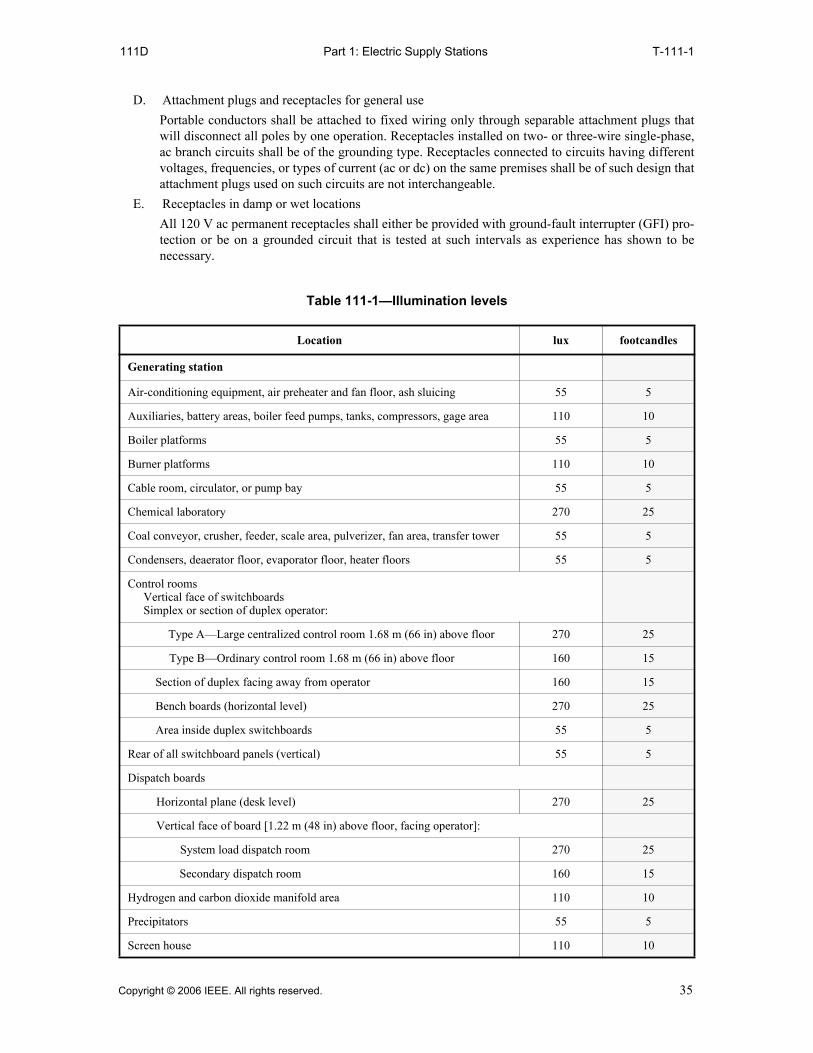
Part 1: Electric Supply Stations111D T-111-1
D. Attachment plugs and receptacles for general use
Portable conductors shall be attached to fixed wiring only through separable attachment plugs thatwill disconnect all poles by one operation. Receptacles installed on two- or three-wire single-phase,ac branch circuits shall be of the grounding type. Receptacles connected to circuits having differentvoltages, frequencies, or types of current (ac or dc) on the same premises shall be of such design thatattachment plugs used on such circuits are not interchangeable.
E. Receptacles in damp or wet locations
All 120 V ac permanent receptacles shall either be provided with ground-fault interrupter (GFI) pro-tection or be on a grounded circuit that is tested at such intervals as experience has shown to benecessary.
Table 111-1—Illumination levels
Location lux footcandles
Generating station
Air-conditioning equipment, air preheater and fan floor, ash sluicing 55 5
Auxiliaries, battery areas, boiler feed pumps, tanks, compressors, gage area 110 10
Boiler platforms 55 5
Burner platforms 110 10
Cable room, circulator, or pump bay 55 5
Chemical laboratory 270 25
Coal conveyor, crusher, feeder, scale area, pulverizer, fan area, transfer tower 55 5
Condensers, deaerator floor, evaporator floor, heater floors 55 5
Control roomsVertical face of switchboardsSimplex or section of duplex operator:
Type A—Large centralized control room 1.68 m (66 in) above floor 270 25
Type B—Ordinary control room 1.68 m (66 in) above floor 160 15
Section of duplex facing away from operator 160 15
Bench boards (horizontal level) 270 25
Area inside duplex switchboards 55 5
Rear of all switchboard panels (vertical) 55 5
Dispatch boards
Horizontal plane (desk level) 270 25
Vertical face of board [1.22 m (48 in) above floor, facing operator]:
System load dispatch room 270 25
Secondary dispatch room 160 15
Hydrogen and carbon dioxide manifold area 110 10
Precipitators 55 5
Screen house 110 10
Copyright © 2006 IEEE. All rights reserved. 35

Part 1: Electric Supply StationsT-111-1 T-111-1
Soot or slag blower platform 55 5
Steam headers and throttles 55 5
Switchgear, power 110 10
Telephone equipment room 110 10
Tunnels or galleries, piping 55 5
Turbine bay sub-basement 110 10
Turbine room 160 15
Visitors’ gallery 110 10
Water treating area 110 10
Generating station (exterior)
Catwalks 22 2
Cinder dumps 2.2 0.2
Coal-storage area 2.2 0.2
Coal unloading
Dock (loading or unloading zone) 55 5
Barge storage area 5.5 0.5
Car dumper 5.5 0.5
Tipple 55 5
Conveyers 22 2
EntrancesGenerating or service building
Main 110 10
Secondary 22 2
Gate house
Pedestrian entrance 110 10
Conveyor entrance 55 5
Fence 2.2 0.2
Fuel-oil delivery headers 55 5
Oil storage tanks 11 1
Open yard 2.2 0.2
Platforms—boiler, turbine deck 55 5
Table 111-1—Illumination levels (continued)
Location lux footcandles
36 Copyright © 2006 IEEE. All rights reserved.
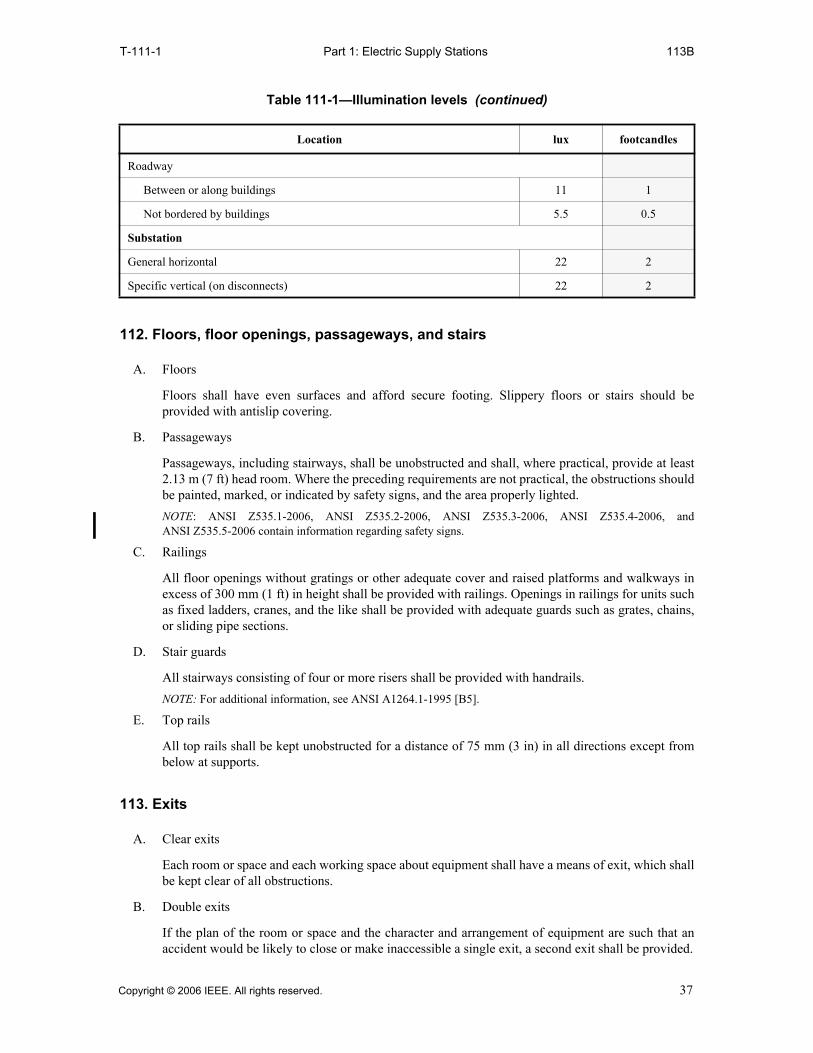
Part 1: Electric Supply StationsT-111-1 113B
112. Floors, floor openings, passageways, and stairs
A. Floors
Floors shall have even surfaces and afford secure footing. Slippery floors or stairs should beprovided with antislip covering.
B. Passageways
Passageways, including stairways, shall be unobstructed and shall, where practical, provide at least2.13 m (7 ft) head room. Where the preceding requirements are not practical, the obstructions shouldbe painted, marked, or indicated by safety signs, and the area properly lighted.
NOTE: ANSI Z535.1-2006, ANSI Z535.2-2006, ANSI Z535.3-2006, ANSI Z535.4-2006, andANSI Z535.5-2006 contain information regarding safety signs.
C. Railings
All floor openings without gratings or other adequate cover and raised platforms and walkways inexcess of 300 mm (1 ft) in height shall be provided with railings. Openings in railings for units suchas fixed ladders, cranes, and the like shall be provided with adequate guards such as grates, chains,or sliding pipe sections.
D. Stair guards
All stairways consisting of four or more risers shall be provided with handrails.
NOTE: For additional information, see ANSI A1264.1-1995 [B5].
E. Top rails
All top rails shall be kept unobstructed for a distance of 75 mm (3 in) in all directions except frombelow at supports.
113. Exits
A. Clear exits
Each room or space and each working space about equipment shall have a means of exit, which shallbe kept clear of all obstructions.
B. Double exits
If the plan of the room or space and the character and arrangement of equipment are such that anaccident would be likely to close or make inaccessible a single exit, a second exit shall be provided.
Roadway
Between or along buildings 11 1
Not bordered by buildings 5.5 0.5
Substation
General horizontal 22 2
Specific vertical (on disconnects) 22 2
Table 111-1—Illumination levels (continued)
Location lux footcandles
Copyright © 2006 IEEE. All rights reserved. 37

Part 1: Electric Supply Stations113C 114
C. Exit doors
Exit doors shall swing out and be equipped with panic bars, pressure plates, or other devices that arenormally latched but open under simple pressure.
EXCEPTION: This rule does not apply to exit doors in buildings and rooms containing low-voltage,nonexplosive equipment, and to gates in fences for outdoor equipment installations.
114. Fire-extinguishing equipment
Fire-extinguishing equipment approved for the intended use shall be conveniently located andconspicuously marked.
38 Copyright © 2006 IEEE. All rights reserved.
Part 1: Electric Supply Stations120 123A
Section 12.Installation and maintenance of equipment
120. General requirements
A. All electric equipment shall be constructed, installed, and maintained so as to safeguard personnel asfar as practical.
B. The rules of this section are applicable to both ac and dc supply stations.
121. Inspections
A. In-service equipment
Electric equipment shall be inspected and maintained at such intervals as experience has shown tobe necessary. Equipment or wiring found to be defective shall be put in good order or permanentlydisconnected.
B. Idle equipment
Infrequently used equipment or wiring shall be inspected and tested before use to determine itsfitness for service. Idle equipment energized but not connected to a load shall be inspected andmaintained at such intervals as experience has shown to be necessary.
C. Emergency equipment
Equipment and wiring maintained for emergency service shall be inspected and tested at suchintervals as experience has shown to be necessary to determine its fitness for service.
D. New equipment
New equipment shall be inspected and tested before being placed in service. New equipment shallbe tested in accordance with standard industry practices.
122. Guarding shaft ends, pulleys, belts, and suddenly moving parts
A. Mechanical transmission machinery
The methods for safeguarding pulleys, belts, and other equipment used in the mechanicaltransmission of power shall be in accordance with ANSI/ASME B15.1-2000.
B. Suddenly moving parts
Parts of equipment that move suddenly in such a way that persons in the vicinity are likely to be in-jured by such movement shall be guarded or isolated.
123. Protective grounding
A. Protective grounding or physical isolation of non-current-carrying metal parts
All electric equipment shall have the exposed non-current-carrying metal parts, such as frames ofgenerators and switchboards, cases of transformers, switches, and operating levers, effectivelygrounded or physically isolated. All metallic guards including rails, screen fences, etc., aboutelectric equipment shall be effectively grounded.
Copyright © 2006 IEEE. All rights reserved. 39

Part 1: Electric Supply Stations123B 124C1
B. Grounding method
All grounding that is intended to be a permanent and effective protective measure, such as surge-arrester grounding, grounding of circuits, equipment, or wire raceways, shall be made in accordancewith the methods specified in Section 9 of this Code.
NOTE: For additional information, see IEEE Std 80-2000 [B32].
C. Provision for grounding equipment during maintenance
Electric equipment or conductors normally operating at more than 600 V between conductors, on orabout which work is occasionally done while isolated from a source of electric energy bydisconnecting or isolating switches only, shall be provided with some means for grounding, such asswitches, connectors, or a readily accessible means for connecting a portable grounding conductor.See Part 4 of this Code.
D. Grounding methods for direct-current systems over 750 V
On dc systems greater than 750 V, the dc system shall be grounded in accordance with the methodsspecified in Section 9 of this Code.
124. Guarding live parts
A. Where required
1. Guards shall be provided around all live parts operating above 300 V phase-to-phase withoutan adequate insulating covering, unless their location gives sufficient horizontal or verticalclearance or a combination of these clearances to limit the likelihood of accidental humancontact. Clearances from live parts to any permanent supporting surface for workers shall equalor exceed either of those shown in Table 124-1 and illustrated in Figure 124-1.
EXCEPTION: Where supplemental protection is used in accordance with Rule 124C3, the requirementsto guard do not apply.
2. Parts over or near passageways through which material may be carried, or in or near spacessuch as corridors, storerooms, and boiler rooms used for nonelectrical work, shall be guardedor given clearances in excess of those specified such as may be necessary to secure reasonablesafety. The guards shall be substantial and completely shield or enclose the live parts withoutopenings. In spaces used for nonelectrical work, guards should be removable only by means oftools or keys.
3. Each portion of parts of indeterminate potential, such as telephone wires exposed to inductionfrom high-voltage lines, ungrounded neutral connections, ungrounded frames, ungroundedparts of insulators or surge arresters, or ungrounded instrument cases connected directly to ahigh-voltage circuit, shall be guarded in accordance with Rule 124A1 on the basis of themaximum voltage that may be present on the surface of that portion. The vertical clearanceabove grade of the bottom of such part shall be not less than 2.60 m (8.5 ft) unless it is enclosedor guarded in accordance with Rule 124C.
B. Strength of guards
Guards shall be sufficiently strong and shall be supported rigidly and securely enough to limit thelikelihood of them being displaced or dangerously deflected by a person slipping or falling againstthem.
C. Types of guards
1. Location or physical isolation
Parts having clearances equal to or greater than specified in Table 124-1 are guarded bylocation. Parts are guarded by isolation when all entrances to enclosed spaces, runways, fixedladders, and the like are kept locked, barricaded, or roped off, and safety signs are posted at allentrances.
40 Copyright © 2006 IEEE. All rights reserved.
Part 1: Electric Supply Stations124C2 124C6b
NOTE: ANSI Z535.1-2006, ANSI Z535.2-2006, ANSI Z535.3-2006, ANSI Z535.4-2006, andANSI Z535.5-2006 contain information regarding safety signs.
2. Shields or enclosures
Guards less than 100 mm (4 in) outside of the guard zone shall completely enclose the partsfrom contact up to the heights listed in column 2 of Table 124-1. They shall be not closer to thelive parts than listed in column 4 of Table 124-1, except when suitable insulating material isused with circuits of less than 2500 V to ground. If more than 100 mm (4 in) outside the guardzone, the guards shall extend at least 2.60 m (8.5 ft) above the floor. Covers or guards, whichmust at any time be removed while the parts they guard are live, shall be so arranged that theycannot readily be brought into contact with live parts.
3. Supplemental barriers or guards within electric supply stations
If the vertical distance in Table 124-1 cannot be obtained, railings or fences may be used.Railings or fences, if used, shall be not less than 1.07 m (3.5 ft) high and shall be located at ahorizontal distance of at least 900 mm (3 ft) [and preferably not more than 1.20 m (4 ft)] fromthe nearest point of the guard zone that is less than 2.60 m (8.5 ft) above the floor or grade (seeFigure 124-2).
NOTE: It is preferred that the railing or fence be located as close as practical to the parts, while providinga sufficient clear distance to the side of the guard zone to allow appropriate working room with expectedtools (such as hot sticks) and working methods—see Rules 125 and 441.
4. Mats
Mats of rubber or other suitable insulating material complying with ASTM D 178-88 may beused at switchboards, switches, or rotating machinery as supplementary protection.
5. Live parts below supporting surfaces for persons
The supporting surfaces for persons above live parts shall be without openings. Toe boards atleast 150 mm (6 in) high and handrails shall be provided at all edges.
6. Insulating covering on conductors or parts
Conductors and parts may be considered as guarded by insulation if they have either of thefollowing:
a. Insulation covering of a type and thickness suitable for the voltage and conditions underwhich they are expected to be operated, and if operating above 2500 V to ground, havingmetallic insulation shielding or semiconducting shield in combination with suitable metal-lic drainage that is grounded to an effective ground.
EXCEPTION: Nonshielded insulated conductors listed by a qualified testing laboratory shall bepermitted for use up to 8000 V (phase to phase) when the conductors meet the requirements of theNEC, Article 310-6.
b. Barriers or enclosures that are electrically and mechanically suitable for the conditionsunder which they are expected to be operated.
Copyright © 2006 IEEE. All rights reserved. 41

Part 1: Electric Supply StationsF-124-1 F-124-2
HORIZONTAL CLEARANCESEE COLUMN 3, TABLE 124-1
GUARD ZONE AT RADIUS R, SEECOLUMN 4, TABLE 124-1
VERTICAL CLEARANCE SEE COLUMN 2, TABLE 124-1
LIVE PART
Figure 124-1—Clearance from live parts
LIVE CONDUCTOR
GUARD
ZONE
LESS THAN 2.60 m (8 ft, 6 in)
(4 ft)1.20 m
2.60 m (8 ft, 6 in)
900 mm (3 ft)
RAILING OR FENCEREQUIRED HERE
Figure 124-2—Railings or fences used as guards
42 Copyright © 2006 IEEE. All rights reserved.
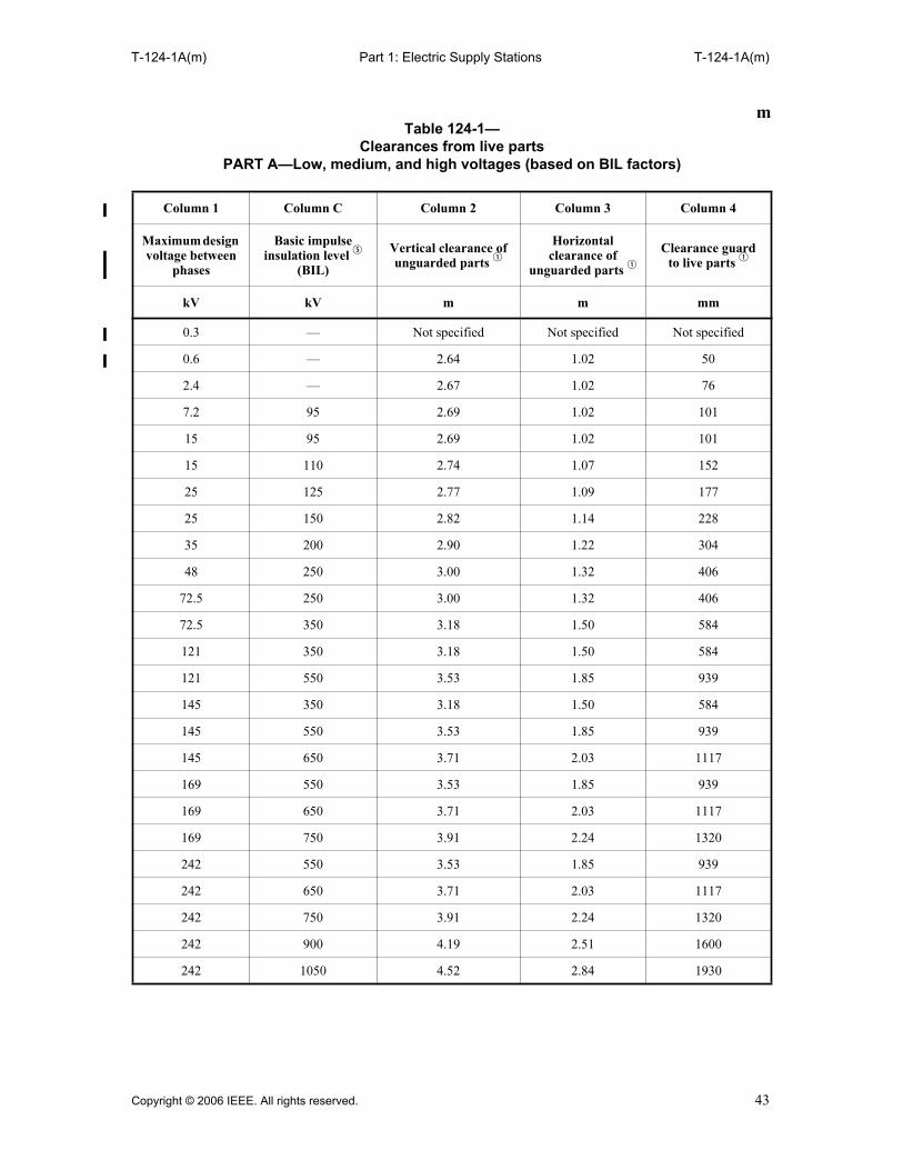
Part 1: Electric Supply StationsT-124-1A(m) T-124-1A(m)
mTable 124-1—
Clearances from live partsPART A—Low, medium, and high voltages (based on BIL factors)
Column 1 Column C Column 2 Column 3 Column 4
Maximum design voltage between
phases
Basic impulse insulation level t
(BIL)
Vertical clearance of unguarded parts q
Horizontal clearance of
unguarded parts qClearance guard
to live parts q
kV kV m m mm
0.3 — Not specified Not specified Not specified
0.6 — 2.64 1.02 50
2.4 — 2.67 1.02 76
7.2 95 2.69 1.02 101
15 95 2.69 1.02 101
15 110 2.74 1.07 152
25 125 2.77 1.09 177
25 150 2.82 1.14 228
35 200 2.90 1.22 304
48 250 3.00 1.32 406
72.5 250 3.00 1.32 406
72.5 350 3.18 1.50 584
121 350 3.18 1.50 584
121 550 3.53 1.85 939
145 350 3.18 1.50 584
145 550 3.53 1.85 939
145 650 3.71 2.03 1117
169 550 3.53 1.85 939
169 650 3.71 2.03 1117
169 750 3.91 2.24 1320
242 550 3.53 1.85 939
242 650 3.71 2.03 1117
242 750 3.91 2.24 1320
242 900 4.19 2.51 1600
242 1050 4.52 2.84 1930
Copyright © 2006 IEEE. All rights reserved. 43

Part 1: Electric Supply StationsT-124-1B(m) T-124-1B(m)
m
Table 124-1— PART B—Extra-high voltages (based on switching-surge factors)
w
Column 1 Column A Column B Column 2 Column 3 Column 4
Maximum design voltage
between phases
Switching- surge factore
per unit r
Switching surge line to
ground r
Vertical clearance of unguarded
parts q
Horizontal clearance of unguarded
parts q
Clearance guard to live
parts q
kV kV m m m
362 2.2 or below 650 4.7 3.0 2.13
362 2.3 680 4.9 3.2 2.30
362 2.4 709 5.0 3.4 2.45
362 2.5 739 5.2 3.6 2.60
362 2.6 768 5.4 3.7 2.80
362 2.7 798 5.6 3.9 3.0
362 2.8 828 5.8 4.1 3.2
362 2.9 857 6.0 4.3 3.4
362 3.0 887 6.1 4.5 3.6
550 1.8 or below 808 5.7 4.1 3.2
550 1.9 853 5.9 4.3 3.4
550 2.0 898 6.2 4.6 3.6
550 2.1 943 6.6 4.9 4.0
550 2.2 988 6.9 5.2 4.3
550 2.3 1033 7.2 5.5 4.6
550 2.4 1078 7.5 5.8 4.9
550 2.5 1123 7.9 6.2 5.3
550 2.6 1167 8.2 6.6 5.6
550 2.7 1212 8.6 7.0 6.0
800 1.5 980 6.8 5.1 4.2
800 1.6 1045 7.3 5.6 4.7
800 1.7 1110 7.8 6.1 5.2
800 1.8 1176 8.3 6.6 5.7
800 1.9 1241 8.8 7.2 6.2
44 Copyright © 2006 IEEE. All rights reserved.
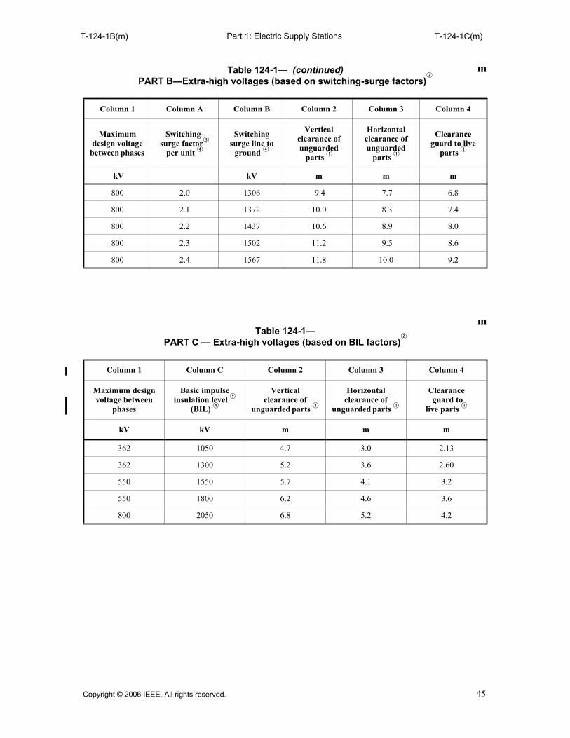
Part 1: Electric Supply StationsT-124-1B(m) T-124-1C(m)
m
800 2.0 1306 9.4 7.7 6.8
800 2.1 1372 10.0 8.3 7.4
800 2.2 1437 10.6 8.9 8.0
800 2.3 1502 11.2 9.5 8.6
800 2.4 1567 11.8 10.0 9.2
Table 124-1—PART C — Extra-high voltages (based on BIL factors)
w
Column 1 Column C Column 2 Column 3 Column 4
Maximum design voltage between
phases
Basic impulse insulation level t
(BIL) r
Verticalclearance of
unguarded parts q
Horizontal clearance of
unguarded parts q
Clearance guard to
live parts q
kV kV m m m
362 1050 4.7 3.0 2.13
362 1300 5.2 3.6 2.60
550 1550 5.7 4.1 3.2
550 1800 6.2 4.6 3.6
800 2050 6.8 5.2 4.2
Table 124-1— (continued)PART B—Extra-high voltages (based on switching-surge factors)
w
Column 1 Column A Column B Column 2 Column 3 Column 4
Maximum design voltage
between phases
Switching- surge factore
per unit r
Switching surge line to
ground r
Vertical clearance of unguarded
parts q
Horizontal clearance of unguarded
parts q
Clearance guard to live
parts q
kV kV m m m
m
Copyright © 2006 IEEE. All rights reserved. 45

Part 1: Electric Supply StationsT-124-1D(m) T-124-1D(m)
m
Table 124-1— PART D — High voltage direct current (based on transient overvoltage)
Column 1 Column A Column B Column 2 Column 3 Column 4
Maximum design voltage conductor to
ground
Transient overvoltage per unit r
Transient overvoltage
line to grnd r
Vertical clearance of unguarded
parts q
Horizontal clearance of unguarded
parts q
Clearance guard to live
partsq
kV kV m m m
250 1.5 or below 375 3.81 2.13 1.22
250 1.6 400 3.89 2.22 1.30
250 1.7 425 3.97 2.30 1.38
250 1.8 450 4.05 2.38 1.46
400 1.5 or below 600 4.54 2.87 1.95
400 1.6 640 4.67 3.00 2.08
400 1.7 680 4.88 3.21 2.29
400 1.8 720 5.12 3.45 2.53
500 1.5 or below 750 5.29 3.62 2.70
500 1.6 800 5.60 3.92 3.01
500 1.7 850 5.96 4.29 3.37
500 1.8 900 6.35 4.67 3.76
600 1.5 or below 900 6.35 4.67 3.76
600 1.6 960 6.73 5.06 4.14
600 1.7 1020 7.13 5.45 4.54
600 1.8 1080 7.57 5.89 4.97
750 1.5 or below 1125 7.90 6.23 5.31
750 1.6 1200 8.44 6.76 5.85
750 1.7 1275 9.06 7.38 6.47
750 1.8 1350 9.72 8.04 7.13
46 Copyright © 2006 IEEE. All rights reserved.

Part 1: Electric Supply StationsT-124-1D(m) T-124-1D(m)
q Interpolate for intermediate values. The clearances in column 4 of this table are solely for guidance in installingguards without definite engineering design and are not to be considered as a requirement for such engineeringdesign. For example, the clearances in the tables above are not intended to refer to the clearances between live partsand the walls of the cells, compartments, or similar enclosing structures. They do not apply to the clearancesbetween bus bars and supporting structures nor to clearances between the blade of a disconnecting switch and itsbase. However, where surge-protective devices are applied to protect the live parts, the vertical clearances, column2 of Table 124-1 Part A may be reduced provided the clearance is not less than 2.6 m plus the electrical clearancebetween energized parts and ground as limited by the surge-protective devices.
wClearances shall satisfy either switching-surge or BIL duty requirements, whichever are greater. eSwitching-surge factor—an expression of the maximum switching-surge crest voltage in terms of the maximum
operating line-to-neutral crest voltage of the power system.rThe values of columns A, B, and C are power system design factors that shall correlate with selected clearances.
Adequate data to support these design factors should be available.tThe selection of station BIL shall be coordinated with surge-protective devices when BIL is used to determine
clearance. BIL—basic impulse insulation level—for definition and application, see IEEE Std 1313-1993.
Copyright © 2006 IEEE. All rights reserved. 47

Part 1: Electric Supply StationsT-124-1A(ft) T-124-1A(ft)
ftTable 124-1—
Clearances from live partsPART A—Low, medium, and high voltages (based on BIL factors)
Column 1 Column C Column 2 Column 3 Column 4
Maximum design voltage between
phases
Basic impulse insulation level t
(BIL)
Vertical clearance of
unguarded parts q
Horizontal clearance of
unguarded parts q
Clearance guard to live
parts q
kV kV ft in ft in ft in
0.3 — Not specified Not specified Not specified
0.6 — 8 8 3 4 0 2
2.4 — 8 9 3 4 0 3
7.2 95 8 10 3 4 0 4
15 95 8 10 3 4 0 4
15 110 9 0 3 6 0 6
25 125 9 1 3 7 0 7
25 150 9 3 3 9 0 9
35 200 9 6 4 0 1 0
48 250 9 10 4 4 1 4
72.5 250 9 10 4 4 1 4
72.5 350 10 5 4 11 1 11
121 350 10 5 4 11 1 11
121 550 11 7 6 1 3 1
145 350 10 5 4 11 1 11
145 550 11 7 6 1 3 1
145 650 12 2 6 8 3 8
169 550 11 7 6 1 3 1
169 650 12 2 6 8 3 8
169 750 12 10 7 4 4 4
242 550 11 7 6 1 3 1
242 650 12 2 6 8 3 8
242 750 12 10 7 4 4 4
242 900 13 9 8 3 5 3
242 1050 14 10 9 4 6 4
48 Copyright © 2006 IEEE. All rights reserved.

Part 1: Electric Supply StationsT-124-1B(ft) T-124-1B(ft)
ftTable 124-1—
PART B — Extra-high voltages (based on switching-surge factors)w
Column 1 Column A Column B Column 2 Column 3 Column 4
Maximum design voltage
between phases
Switching surge factorper unit r
Switching surge line to
groundr
Vertical clearance of unguarded
partsq
Horizontal clearance of unguarded
partsq
Clearance guard to live
partsq
kV kv ft in ft in ft in
362 2.2 or below 650 15 6 10 0 7 0
362 2.3 680 16 0 10 6 7 6
362 2.4 709 16 6 11 0 8 0
362 2.5 739 17 2 11 8 8 8
362 2.6 768 17 9 12 3 9 3
362 2.7 798 18 4 12 10 9 10
362 2.8 828 18 11 13 5 10 5
362 2.9 857 19 7 14 1 11 1
362 3.0 887 20 2 14 8 11 8
550 1.8 or below 808 18 10 13 4 10 4
550 1.9 853 19 6 14 0 11 0
550 2.0 898 20 6 15 0 12 0
550 2.1 943 21 6 16 0 13 0
550 2.2 988 22 6 17 0 14 0
550 2.3 1033 23 7 18 1 15 1
550 2.4 1078 24 8 19 2 16 2
550 2.5 1123 25 10 20 4 17 4
550 2.6 1167 27 0 21 6 18 6
550 2.7 1212 28 4 22 10 19 10
800 1.5 980 22 4 16 10 13 10
800 1.6 1045 23 11 18 5 15 5
800 1.7 1110 25 6 20 0 17 1
800 1.8 1176 27 3 21 9 18 9
800 1.9 1241 29 0 23 6 2 6
800 2.0 1306 30 10 25 4 22 4
800 2.1 1372 32 9 27 3 24 3
800 2.2 1437 34 8 29 3 26 2
800 2.3 1502 36 9 31 3 28 3
800 2.4 1567 38 9 33 3 30 3
Copyright © 2006 IEEE. All rights reserved. 49

Part 1: Electric Supply StationsT-124-1C(ft) T-124-1D(ft)
ftTable 124-1—
PART C — Extra-high voltages (based on BIL factors)w
Column 1 Column C Column 2 Column 3 Column 4
Maximum design voltage
between phases
Basic impulse insulation
level t
(BIL)r
Verticalclearance of
unguarded parts q
Horizontalclearance of
unguarded parts q
Clearanceguard to
live parts q
kV kV ft in ft in ft in
362 1050 15 6 10 0 7 0
362 1300 17 2 11 8 8 8
550 1550 18 10 13 4 10 4
550 1800 20 6 15 0 12 0
800 2050 22 5 16 11 13 11
Table 124-1— PART D — High voltage direct current (based on transient overvoltage)
Column 1 Column A Column B Column 2 Column 3 Column 4
Maximum design voltage conductor to
ground
Transient overvoltage per unit r
Transient overvoltage
line to grnd r
Vertical clearance of unguarded
parts q
Horizontal clearance of unguarded
parts q
Clearance guard to live
partsq
kV kV ft in ft in ft in
250 1.5 or below 375 12 6 7 0 4 0
250 1.6 400 12 9 7 3 4 3
250 1.7 425 13 0 7 7 4 6
250 1.8 450 13 3 7 10 4 9
400 1.5 or below 600 14 11 9 5 6 5
400 1.6 640 15 4 9 10 6 10
400 1.7 680 16 0 10 6 7 6
400 1.8 720 16 10 11 4 8 4
500 1.5 or below 750 17 4 11 11 8 10
500 1.6 800 18 4 12 10 9 11
500 1.7 850 19 7 14 1 11 1
500 1.8 900 20 10 15 4 12 4
ft
50 Copyright © 2006 IEEE. All rights reserved.
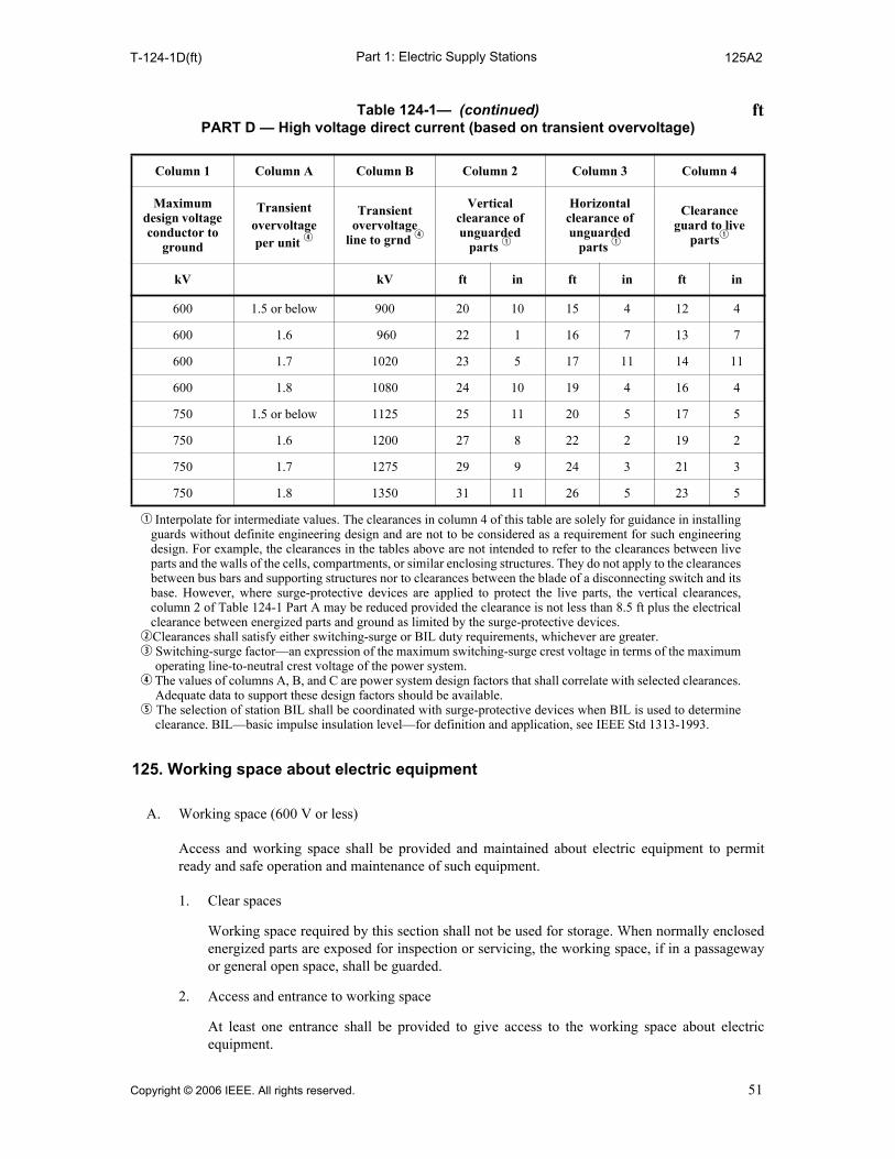
Part 1: Electric Supply StationsT-124-1D(ft) 125A2
125. Working space about electric equipment
A. Working space (600 V or less)
Access and working space shall be provided and maintained about electric equipment to permitready and safe operation and maintenance of such equipment.
1. Clear spaces
Working space required by this section shall not be used for storage. When normally enclosedenergized parts are exposed for inspection or servicing, the working space, if in a passagewayor general open space, shall be guarded.
2. Access and entrance to working space
At least one entrance shall be provided to give access to the working space about electricequipment.
600 1.5 or below 900 20 10 15 4 12 4
600 1.6 960 22 1 16 7 13 7
600 1.7 1020 23 5 17 11 14 11
600 1.8 1080 24 10 19 4 16 4
750 1.5 or below 1125 25 11 20 5 17 5
750 1.6 1200 27 8 22 2 19 2
750 1.7 1275 29 9 24 3 21 3
750 1.8 1350 31 11 26 5 23 5
q Interpolate for intermediate values. The clearances in column 4 of this table are solely for guidance in installingguards without definite engineering design and are not to be considered as a requirement for such engineeringdesign. For example, the clearances in the tables above are not intended to refer to the clearances between liveparts and the walls of the cells, compartments, or similar enclosing structures. They do not apply to the clearancesbetween bus bars and supporting structures nor to clearances between the blade of a disconnecting switch and itsbase. However, where surge-protective devices are applied to protect the live parts, the vertical clearances,column 2 of Table 124-1 Part A may be reduced provided the clearance is not less than 8.5 ft plus the electricalclearance between energized parts and ground as limited by the surge-protective devices.
wClearances shall satisfy either switching-surge or BIL duty requirements, whichever are greater. e Switching-surge factor—an expression of the maximum switching-surge crest voltage in terms of the maximum
operating line-to-neutral crest voltage of the power system.r The values of columns A, B, and C are power system design factors that shall correlate with selected clearances.
Adequate data to support these design factors should be available.t The selection of station BIL shall be coordinated with surge-protective devices when BIL is used to determine
clearance. BIL—basic impulse insulation level—for definition and application, see IEEE Std 1313-1993.
Table 124-1— (continued)PART D — High voltage direct current (based on transient overvoltage)
Column 1 Column A Column B Column 2 Column 3 Column 4
Maximum design voltage conductor to
ground
Transient overvoltage per unit r
Transient overvoltage
line to grnd r
Vertical clearance of unguarded
parts q
Horizontal clearance of unguarded
parts q
Clearance guard to live
partsq
kV kV ft in ft in ft in
ft
Copyright © 2006 IEEE. All rights reserved. 51

Part 1: Electric Supply Stations125A3 127
3. Working space
The working space in the direction of access to energized parts operating at 600 V or less thatrequire examination, adjustment, servicing, or maintenance while energized shall be not lessthan indicated in Table 125-1. In addition to the dimensions shown in Table 125-1, the workingspace shall be not less than 750 mm (30 in) wide in front of the electric equipment. Distancesshall be measured from the energized parts if such are exposed or from the enclosure front oropening if such are enclosed. Concrete, brick, or tile walls shall be considered grounded.
4. Headroom working space
The headroom of working spaces about switchboards or control centers shall be not less than2.13 m (7 ft).
5. Front working space
In all cases where there are energized parts normally exposed on the front of switchboards ormotor control centers, the working space in front of such equipment shall not be less than900 mm (3 ft).
B. Working space over 600 V
Working space shall be in accordance with Table 124-1.
126. Equipment for work on energized parts
When it is necessary for personnel to move themselves, material, or tools within the guard zone ofunguarded energized parts, protective equipment shall be provided.
This protective equipment shall be periodically inspected, tested, and kept in a safe condition.Protective equipment shall be rated for not less than the voltage involved. Refer to Section 3 for alist of specifications for equipment.
127. Classified locations
Electrical installations in classified areas shall meet the requirements of the NEC, Articles 500through 517. Areas classified in accordance with NEC Article 500 shall comply with the
Table 125-1—Working space
Voltage to ground
Clear distance
Condition 1 Condition 2 Condition 3
mm ft mm ft mm ft
0–150 900 3 900 3 900 3
151–600 900 3 1070 3-1/2 1200 4
Where the conditions are as follows: 1. Exposed energized parts on one side and no energized or grounded parts on the other side of the working space,
or exposed energized parts on both sides effectively guarded by suitable wood or other insulating materials. In-sulated wire or insulated bus bars operating at not over 300 V shall not be considered energized parts.
2. Exposed energized parts on one side and grounded parts on the other side. 3. Exposed energized parts on both sides of the work space (not guarded as provided in Condition 1) with the op-
erator between. EXCEPTION: Working space shall not be required in back of assemblies, such as dead-front switchboards or motor
control centers where there are no renewable or adjustable parts such as fuses or switches on the back and whereall connections are accessible from locations other than the back.
52 Copyright © 2006 IEEE. All rights reserved.

Part 1: Electric Supply Stations127A 127B4a
requirements of that Article and A. through L. below. Areas classified with the optional Zonemethod in accordance with NEC Article 505 shall comply with the requirements of that article.
A. Coal-handling areas
1. Unventilated spaces inside or above coal-storage silos or bunkers, or other enclosed coal-storage and coal-handling spaces where methane may accumulate in explosive or ignitablemixtures as defined in Article 500-5 of the NEC, are Class I, Division 1, Group D locations.Electric equipment in other locations in which flammable gases or vapors may exist shall be inaccordance with the NEC, Article 500-5, or the locations shall be adequately ventilated.
2. Adequate ventilation exists when the method of ventilation will limit the likelihood ofaccumulation of significant quantities of vapor-air concentrations from exceeding 25% of thelower flammable limit.
3. Tunnels beneath stockpiles or surge piles; spaces inside, above, or below coal-storage silos orbunkers; or other enclosed coal-storage or coal-handling spaces or areas shall be Class II,Group F, Division 1 or Division 2 locations as determined by the NEC.
4. Enclosed sections where only wet coal is handled, or enclosed sections so cut off as to be freefrom dangerous amounts of coal dust, are not classified. Coal shall be considered to be wet ifenough water sprays are installed and maintained to limit the atmospheric concentration of totalentrapped volatiles to 8% or less. (See ASTM D 3175 for coal and coke dusts).
5. Locations having completely dust-tight pulverized fuel systems designed and installed incompliance with NFPA 8503-1997 shall not be considered classified.
6. Portable lamps for use in fuel bunkers or bins shall be suitable for Class II, Division 1locations.
7. Sparking electric tools shall not be used where combustible dust or dust clouds are present.
8. An equipment grounding conductor shall be carried with the power conductors and serve toground the frames of all equipment supplied from that circuit. The origin of the groundingconductor shall be:
a. Ungrounded delta or wye-transformer frame ground.
b. Grounded delta or wye-transformer grounded secondary connection.
c. Resistance grounded wye—the grounded side of the grounding resistor.
9. Ungrounded systems should be equipped with a ground-fault indicating device to give both avisual and audible alarm upon the occurrence of a ground fault in the system.
B. Flammable and combustible liquids
1. Flammable liquid shall mean a liquid having a flash point below 38 °C (100 °F) and having avapor pressure not exceeding 275 kPa (40 lb/in2) (absolute) at 38 °C (100 °F) and shall beknown as a Class I liquid.
2. Combustible liquid shall mean a liquid having a flash point greater than or equal to 38 °C(100 °F) and having a vapor pressure not exceeding 275 kPa (40 lb/in2) (absolute) at 38 °C(100 °F).
3. Class I liquids are subdivided as follows:
a. Class IA includes those having flash points below 23 °C (73 °F) and having a boilingpoint below 38 °C (100 °F).
b. Class IB includes those having flash points below 23 °C (73 °F).
c. Class IC includes those having flash points at or above 23 °C (73 °F) and below 38 °C(100 °F).
4. Combustible liquids are subdivided as follows:
a. Class II includes those having flash points equal to or greater than 38 °C (100 °F) but lessthan 60 °C (140 °F).
Copyright © 2006 IEEE. All rights reserved. 53
Part 1: Electric Supply Stations127B4b 127H2
b. Class IIIA includes those having flash points equal to or greater than 60 °C (140 °F) butless than 93 °C (200 °F).
c. Class IIIB includes those having flash points greater than or equal to 93 °C (200 °F).
C. Flammable liquid storage area
Electric wiring and equipment located in flammable liquid storage areas shall be installed inaccordance with applicable sections of NFPA 30-2000 and the NEC.
D. Loading and unloading facilities for flammable and combustible liquids
Electric equipment located in the area shall be installed in accordance with applicable sections ofNFPA 30-2000 and the NEC.
E. Gasoline-dispensing stations
Electric equipment installed in areas used for dispensing flammable liquids shall be installed inaccordance with applicable sections of NFPA 30A-2000 and the NEC.
F. Boilers
When storing, handling, or burning fuel oils that have flash points below 38 °C (100 °F) theinstallation shall conform to NFPA 30-2000 and the NEC.
NOTE: Attention must be given to electrical installations in areas where flammable vapors or gases may bepresent in the atmosphere. Typical locations are burner areas, fuel-handling equipment areas, fuel-storageareas, pits, sumps, and low spots where fuel leakage or vapors may accumulate. The NEC, Article 500 providesfor classifying such areas and defines requirements for electrical installations in the areas so classified. Theburner front piping and equipment shall be designed and constructed to eliminate hazardous concentrations offlammable gases that exist continuously, intermittently, or periodically under normal operating conditions.Providing the burners are thoroughly purged before removal for cleaning, burner front maintenance operationswill not cause hazardous concentrations of flammable vapors to exist frequently. With such provisions, theburner front is not normally classified more restrictively than Class I, Division 2.
G. Gaseous hydrogen systems for supply equipment
1. Outdoor storage areas shall not be located beneath electric power lines.
2. Safety considerations at specific storage areas.
Electric equipment shall be suitable for Class I, Division 2 locations:
a. Within 4.6 m (15 ft) of outdoor storage spaces
b. Within adequately ventilated separate buildings or special rooms for storing hydrogen
c. Within 7.6 m (25 ft) of a hydrogen storage space in an adequately ventilated building usedfor other purposes
3. Space around elements of the generator hydrogen seal oil system shall not be consideredclassified for electrical installation except where external venting is not provided in the bearingdrain system.
4. Spaces around the hydrogen piping system beyond the point where the hydrogen storagesystem connects to distribution piping shall not be considered classified for electricalinstallations, outside the boundaries established in 127G2a and 127G2c.
H. Liquid hydrogen systems
1. Electric wiring and equipment located within 900 mm (3 ft) of a point where connections areregularly made and disconnected shall be in accordance with the NEC, Article 501, Class I,Group B, Division 1 locations.
2. Except as provided in Paragraph 1, electric wiring and equipment located within 7.6 m (25 ft)of a point where connections are regularly made and disconnected or within 7.6 m (25 ft) of aliquid hydrogen storage container, shall be in accordance with the NEC, Article 501, Class I,Group B, Division 2 locations. When equipment approved for Class I, Group B atmospheres isnot commercially available, the equipment may be (1) purged or ventilated in accordance with
54 Copyright © 2006 IEEE. All rights reserved.
Part 1: Electric Supply Stations127I 129
NFPA 496-1998, (2) intrinsically safe, or (3) approved for Class I, Group C atmospheres. Thisrequirement does not apply to electric equipment that is installed on mobile supply trucks ortank cars from which the storage container is filled.
I. Sulfur
1. Electric wiring and equipment located in areas where sulfur dust is in suspension in explosiveor ignitable mixtures during normal operations shall be suitable for Class II, Division 1,Group G.
J. Oxygen
1. Bulk oxygen installations are not defined as classified locations.
K. Liquefied petroleum gas (LPG)
Electric equipment and wiring installed in areas used for handling, storage, or utilization of LPGshall be installed in accordance with applicable sections of NFPA 58-2001, NFPA 59-2001, and theNEC.
L. Natural gas (methane)
Electric equipment and wiring installed in areas used for handling, storage, or utilization of naturalgas shall be installed in accordance with applicable sections of NFPA 59A-1990 and the NEC.
NOTE: NFPA 497M-1997 [B61] and API RP500, 7 January 1998 [B17], provide additional guidelines forclassifying these areas.
128. Identification
Electric equipment and devices shall be identified for safe use and operation. The identification shallbe as nearly uniform as practical throughout any one station. Identification marks shall not be placedon removable covers or doors that could be interchanged.
129. Mobile hydrogen equipment
Mobile hydrogen supply units being used to replenish a hydrogen system shall be bonded both to thegrounding system and to the grounded parts of the hydrogen system.
Copyright © 2006 IEEE. All rights reserved. 55

Part 1: Electric Supply Stations130 131
Section 13.Rotating equipment
Rotating equipment includes generators, motors, motor generators, and rotary converters.
130. Speed control and stopping devices
A. Automatic overspeed trip device for prime movers
When harmful overspeed can occur, prime movers driving generating equipment shall be providedwith automatic overspeed trip devices in addition to their governors.
B. Manual stopping devices
An operator-initiated stopping device shall be provided for any machine that drives an electricpower generator or rotary uninterruptible power supply (motor-generator). The operator-initiatedstopping device shall be accessible to the operator during normal operation. Manual controls to beused in emergency for machinery and electric equipment shall be located so as to provide protectionto the operator in the event of such emergency.
C. Speed limit for motors
Machines of the following types shall be provided with speed-limiting devices unless their inherentcharacteristics or the load and the mechanical connection thereto are such as to safely limit thespeed.
1. Separately excited dc motors
2. Series motors
D. Number 130D not used in this edition.
E. Adjustable-speed motors
Adjustable-speed motors, controlled by means of field regulation, shall, in addition to the provisionsof Rule 130C, be so equipped and connected that the field cannot be weakened sufficiently to permitdangerous speed.
F. Protection of control circuits
Where speed-limiting or stopping devices and systems are electrically operated, the control circuitsby which such devices are actuated shall be protected from mechanical damage. Such devices andsystems should be of the automatic tripping type.
131. Motor control
All motors arranged such that an unexpected starting of the motor might create an exposure ofpersonnel to injury shall have the motor control circuit designed to block unintended re-energizationof the motor after a power supply interruption of a duration sufficient for moving equipment tobecome stationary. The motor control shall be such that an operator must take some action to restartthe motor, or automatic restarting shall be preceded by warning signals and a time delay sufficientfor personnel action to limit the likelihood of injury. This requirement does not apply to thosemotors with an emergency use and where the opening of the circuit may cause less safe conditions.
56 Copyright © 2006 IEEE. All rights reserved.
Part 1: Electric Supply Stations132 133
132. Number 132 not used in this edition.
133. Short-circuit protection
Means shall be provided to automatically disconnect an electric motor from the supply source in theevent of high-magnitude short-circuit currents within the motor.
Copyright © 2006 IEEE. All rights reserved. 57

Part 1: Electric Supply Stations140 146A3
Section 14.Storage batteries
140. General
The provisions of this section are intended to apply to all stationary installations of storage batteries.For operating precautions, see Part 4 of this Code.
Space shall be provided around batteries for safe inspection, maintenance, testing, and cellreplacement and space left above the cells to allow for operation of lifting equipment when required,addition of water, and taking measurements.
141. Location
Storage batteries shall be located within a protective enclosure or area accessible only to qualifiedpersons. A protective enclosure can be a battery room, control building, or a case, cage, or fence thatwill protect the contained equipment and limit the likelihood of inadvertent contact with energizedparts.
142. Ventilation
The battery area shall be ventilated, either by a natural or powered ventilation system to limithydrogen accumulation to less than an explosive mixture. Failure of a continuously operated orautomatically controlled powered ventilation system required by design to limit hydrogenaccumulation to less than an explosive mixture shall be annunciated.
143. Racks
Racks refer to frames designed to support cells or trays. Racks shall be firmly anchored, preferablyto the floor. Anchoring to both walls and floors is not recommended. Racks made of metal shall begrounded.
144. Floors in battery areas
Floors of battery areas should be of an acid-resistive material, painted with acid-resistive paint, orotherwise protected. Provision should be made to contain spilled electrolyte.
145. Illumination for battery areas
Lighting fixtures shall be protected from physical damage by guards or isolation. Receptacles andlighting switches should be located outside of battery areas.
146. Service facilities
A. Proper eye protection and clothing shall be provided in the battery area during battery maintenanceand installation and shall consist of the following:
1. Goggles or face shield
2. Acid-resistant gloves
3. Protective aprons and overshoes
58 Copyright © 2006 IEEE. All rights reserved.

Part 1: Electric Supply Stations146A4 146B
4. Portable or stationary water facilities or neutralizing agent for rinsing eyes and skin
B. Safety signs inside and outside of a battery room or in the vicinity of a battery area, prohibitingsmoking, sparks, or flame shall be provided.
NOTE: ANSI Z535.1-2006, ANSI Z535.2-2006, ANSI Z535.3-2006, ANSI Z535.4-2006, andANSI Z535.5-2006 contain information regarding safety signs.
Copyright © 2006 IEEE. All rights reserved. 59

Part 1: Electric Supply Stations150 152B3
Section 15.Transformers and regulators
150. Current-transformer secondary circuits protection when exceeding 600 V
Secondary circuits, when in the vicinity of primary circuits exceeding 600 V should, except for shortlead lengths at the terminals of the transformer, have the secondary wiring adequately protected bymeans of conduit, covering, or some other protection. Any metallic covering used shall beeffectively grounded, giving appropriate consideration to circulating currents. Current transformersshall have provision for shorting the secondary winding.
151. Grounding secondary circuits of instrument transformers
The secondary circuits of instrument transformers shall be effectively grounded where functionalrequirements permit.
152. Location and arrangement of power transformers and regulators
A. Outdoor installations
1. Power transformers and regulators shall be so installed that all energized parts are enclosed orguarded so as to limit the likelihood of inadvertent contact, or the energized parts shall bephysically isolated in accordance with Rule 124. The case shall be effectively grounded orguarded.
2. The installation of liquid-filled transformers shall utilize one or more of the following methodsto minimize fire hazards. The method to be applied shall be according to the degree of the firehazard. Recognized methods are the use of less flammable liquids, space separation, fire-resistant barriers, automatic extinguishing systems, absorption beds, and enclosures.
The amount and characteristics of liquid contained should be considered in the selection ofspace separation, fire-resistant barriers, automatic extinguishing systems, absorption beds, andenclosures that confine the liquid of a ruptured transformer tank, all of which are recognized assafeguards.
B. Indoor installations
1. Transformers and regulators 75 kVA and above containing an appreciable amount offlammable liquid and located indoors shall be installed in ventilated rooms or vaults separatedfrom the balance of the building by fire walls. Doorways to the interior of the building shall beequipped with fire doors and shall have means of containing the liquid.
2. Transformers or regulators of the dry type or containing a nonflammable liquid or gas may beinstalled in a building without a fireproof enclosure. When installed in a building used for otherthan station purposes, the case or the enclosure shall be so designed that all energized parts areenclosed in the case that is grounded in accordance with Rule 123. As an alternate, the entireunit may be enclosed so as to limit the likelihood of inadvertent contact by persons with anypart of the case or wiring. When installed, the pressure-relief vent of a unit containing anonbiodegradable liquid shall be furnished with a means for absorbing toxic gases.
3. Transformers containing less flammable liquid may be installed in a supply station building insuch a way as to minimize fire hazards. The amount of liquid contained, the type of electricalprotection, and tank venting shall be considered in the selection of space separation fromcombustible materials or structures, liquid confinement, fire-resistant barriers or enclosures, orextinguishing systems.
60 Copyright © 2006 IEEE. All rights reserved.

Part 1: Electric Supply Stations153 153
153. Short-circuit protection of power transformers
Power transformers shall be provided with means to disconnect automatically the source of supplyof current for a high magnitude short circuit (fault) within the transformer.
The devices for automatically disconnecting the source of supply may be a circuit breaker, circuitswitcher, fuse, thyristor blocking, or other reasonable methods either locally or remotely connectedto the transformer. This includes disconnecting the generator electric field source together with thesource of mechanical energy upon detection of a fault in either the generator step-up or stationauxiliary transformer. Removing a single phase rather than all three phases to extinguish short-circuit current is acceptable.
EXCEPTION: Transformers other than power transformers are exempt from this rule. This includes instrumenttransformers, neutral grounding transformers, regulating transformers, and other transformers specifically forcontrol, protection, or metering.
Copyright © 2006 IEEE. All rights reserved. 61

Part 1: Electric Supply Stations
62 Copyright © 2006 IEEE. All rights reserved.
Section 16.Conductors
160. Application
Conductors shall be suitable for the location, use, and voltage. Conductors shall have ampacity thatis adequate for the application.
161. Electrical protection
A. Overcurrent protection required
Conductors and insulation shall be protected against excessive heating by the design of the systemand by overcurrent, alarm, indication, or trip devices.
B. Grounded conductors
Conductors normally grounded for the protection of persons shall be arranged without overcurrentprotection or other means that could interrupt their continuity to ground.
C. Insulated power cables
Insulated power cable circuits shall be provided with short-circuit protection that will isolate theshort circuit from the supply.
162. Mechanical protection and support
A. All conductors shall be adequately supported to withstand forces caused by the maximum short-circuit current to which they may be subjected. Where supported conductors extend outside theelectric supply station, such conductors and their supports shall comply with the grades ofconstruction, strength, and loading requirements of Part 2 of this Code.
B. Where conductors, conductor insulation, or conductor supports may be subjected to mechanicaldamage, casing, armor, or other means shall be employed to limit the likelihood of damage ordisturbance.
163. Isolation
All nonshielded insulated conductors of more than 2500 V to ground and bare conductors of morethan 150 V to ground shall be isolated by elevation or guarded in accordance with Rule 124.
Nonshielded, insulated, and jacketed conductors may be installed in accordance with Rule 124C6.
164. Conductor terminations
A. Insulation
Ends and joints of insulated conductors, unless otherwise adequately guarded, shall have insulatingcovering equivalent to that of other portions of the conductor.
B. Metal-sheathed or shielded cable
Insulation of the conductors, where leaving the metal sheath or shield, shall be protected frommechanical damage, moisture, and excessive electrical stress.
160 164B

Part 1: Electric Supply Stations170 174
Section 17.Circuit breakers, reclosers, switches, and fuses
170. Arrangement
Circuit breakers, reclosers, switches, and fuses shall be so installed as to be accessible only topersons qualified for operation and maintenance. Walls, barriers, latched doors, location, isolation,or other means shall be provided to protect persons from energized parts or arcing. Conspicuousmarkings (such as numbers/letters/symbols) shall be provided on each device and at any remoteoperating points so as to facilitate identification by employees authorized to operate the device. Nodevice identification shall be duplicated within the same supply station. When the contact parts of aswitching device are not normally visible, the device shall be equipped with an indicator to show allnormal operating positions.
171. Application
Circuit breakers, circuit switchers, reclosers, switches, and fuses should be utilized with due regardto their assigned ratings of voltage and continuous and momentary currents. Devices that areintended to interrupt fault current shall be capable of safely interrupting the maximum short-circuitcurrent they are intended to interrupt, and for the circumstances under which they are designed tooperate. The interrupting capacity should be reviewed prior to each significant system change.
172. Circuit breakers, reclosers, and switches containing oil
Circuit-interrupting devices containing flammable liquids shall be adequately segregated from otherequipment and buildings to limit damage in the event of an explosion or fire. Segregation may beprovided by spacing, by fire-resistant barrier walls, or by metal cubicles. Gas-relief vents should beequipped with oil-separating devices or piped to a safe location. Means shall be provided to controloil that could be discharged from vents or by tank rupture. This may be accomplished by absorptionbeds, pits, drains, or by any combination thereof. Buildings or rooms housing this equipment shallbe of fire-resistant construction.
173. Switches and disconnecting devices
A. Capacity
Switches shall be of suitable voltage and ampere rating for the circuit in which they are installed.Switches used to break load current shall be marked with the current that they are rated to interrupt.
B. Provisions for disconnecting
Switches and disconnectors shall be so arranged that they can be locked in the open and closedpositions, or plainly tagged where it is not practical to install locks. (See Part 4 of this Code.) Fordevices that are operated remotely and automatically, the control circuit shall be provided with apositive disconnecting means near the apparatus to limit the likelihood of accidental operation of themechanism.
174. Disconnection of fuses
Fuses in circuits of more than 150 V to ground or more than 60 A shall be classified asdisconnecting fuses or be so arranged that before handling:
Copyright © 2006 IEEE. All rights reserved. 63

Part 1: Electric Supply Stations174A 174B
A. The fuses can be disconnected from all sources of electric energy, or
B. The fuses can be conveniently removed by means of insulating handles.
Fuses can be used to disconnect from the source when they are so rated.
64 Copyright © 2006 IEEE. All rights reserved.
Part 1: Electric Supply Stations180 180B5
Section 18.Switchgear and metal-enclosed bus
180. Switchgear assemblies
A. General requirements for all switchgear
1. To minimize movement, all switchgear shall be secured in a manner consistent with conditionsof service and applicable manufacturer’s instructions.
2. Cable routed to switchgear shall be supported to minimize forces applied to conductorterminals.
3. Piping containing liquids, or corrosive or hazardous gases, shall not be routed in the vicinity ofswitchgear unless suitable barriers are installed to protect the switchgear from damage in theevent of a pipe failure.
4. Switchgear shall not be located where foreign flammable or corrosive gases or liquids routinelyand normally are discharged. Companion equipment such as transformers and switchgear arenot considered foreign.
5. Switchgear should not be installed in a location that is still specifically under activeconstruction, especially where welding and burning are required directly overhead. Specialprecautions should be observed to minimize impingement of slag, metal filings, moisture, dust,or hot particles.
EXCEPTION: Switchgear may be installed in a general construction area if suitable temporary protectionis provided to minimize the risks associated with general construction activities.
6. Precautions shall be taken to protect energized switchgear from damage when maintenance isperformed in the area.
7. Switchgear enclosure surfaces shall not be used as physical support for any item unlessspecifically designed for that purpose.
8. Enclosure interiors shall not be used as storage areas unless specifically designed for thatpurpose.
9. Metal instrument cases shall be grounded and enclosed in covers that are metal and grounded,or are of insulating material.
B. Metal-enclosed power switchgear
1. Switchgear shall not be located within 7.6 m (25 ft) horizontally indoors or 3.0 m (10 ft)outdoors of storage containers, vessels, utilization equipment, or devices containing flammableliquids or gases.
EXCEPTION: If an intervening barrier, designed to mitigate the potential effects of flammable liquids orgases, is installed, the distances listed above do not apply.
NOTE: Rule 180B1 is not intended to apply to the power transformer(s) supplying the switchgear.
2. Enclosed switchgear rooms shall have at least two means of egress, one at each extreme of thearea, not necessarily in opposite walls. Doors shall swing out and be equipped with panic bars,pressure plates, or other devices that are normally latched but open under simple pressure.
EXCEPTION: One door may be used when required by physical limitations if means are provided forunhampered exit during emergencies.
3. Space shall be maintained in front of switchgear to allow breakers to be removed and turnedwithout obstruction.
4. Space shall be maintained in the rear of the switchgear to allow for door opening to at least 90degrees open, or a minimum of 900 mm (3 ft) without obstruction when removable panels areused.
5. Permanently mounted devices, panelboards, etc., located on the walls shall not encroach on thespace requirements in 180B4.
Copyright © 2006 IEEE. All rights reserved. 65

Part 1: Electric Supply Stations180B6 181A2
6. Where columns extend into the room beyond the wall surface, the face of the column shall notencroach on the space requirements in 180B4.
7. Low-voltage cables or conductors, except those to be connected to equipment within thecompartment, shall not be routed through the medium- or high-voltage divisions of switchgearunless installed in rigid metal conduit or isolated by rigid metal barriers.
8. Low-voltage conductors routed from medium- or high-voltage sections of switchgear shallterminate in a low-voltage section before being routed external to the switchgear.
9. Conductors entering switchgear shall be insulated for the higher operating voltage in thatcompartment or be separated from insulated conductors of other voltage ratings.
10. Switchgear enclosures shall be suitable for the environment in which they are installed.
11. A safety sign shall be placed in each cubicle containing more than one high-voltage source.
NOTE: ANSI Z535.1-2006, ANSI Z535.2-2006, ANSI Z535.3-2006, ANSI Z535.4-2006, andANSI Z535.5-2006 contain information regarding safety signs.
12. The location of control devices shall be readily accessible to personnel. Instruments, relays, andother devices requiring reading or adjustments should be so placed that work can readily beperformed from the working space.
C. Dead-front power switchboards
Dead-front power switchboards with uninsulated rear connections shall be installed in rooms orspaces that are capable of being locked, with access limited to qualified personnel.
D. Motor control centers
1. Motor control centers shall not be connected to systems having higher short-circuit capabilitythan the bus bracing can withstand. Where current-limiting fuses are employed on the sourceside of the bus, the bus bracing and breaker-interrupting rating are determined by the peak let-through characteristic of the current-limiting fuse.
2. A safety sign shall be placed in each cubicle containing more than one voltage source.
NOTE: ANSI Z535.1-2006, ANSI Z535.2-2006, ANSI Z535.3-2006, ANSI Z535.4-2006, andANSI Z535.5-2006 contain information regarding safety signs.
E. Control switchboards
1. Cabinets containing solid-state logic devices, electron tubes, or relay logic devices such asboiler analog, burner safety, annunciators, computers, inverters, precipitator logic, soot blowercontrol, load control, telemetering, totalizing microwave radio, etc., are covered under theserules.
2. Where carpeting is installed in rooms containing control switchboards, it shall be of anantistatic type and shall minimize the release of noxious, corrosive, caustic, or toxic gas underany condition.
3. Layout of the installation shall provide adequate clearance in front of, or rear of, panels ifapplicable, to allow meters to be read without use of stools or auxiliary devices.
4. Where personnel access to control panels, such as benchboards, is required, cables shall berouted through openings separate from the personnel opening. Removable, sliding, or hingedpanels are to be installed to close the personnel opening when not in use.
181. Metal-enclosed bus
A. General requirements for all types of bus
1. Busways shall be installed only in accessible areas.
2. Busways, unless specifically approved for the purpose, shall not be installed: where subject tosevere physical damage or corrosive vapors; in hoistways; in any classified hazardous location;outdoors or in damp locations.
66 Copyright © 2006 IEEE. All rights reserved.

Part 1: Electric Supply Stations181A3 181B5
3. Deadends of busway shall be closed.
4. Busways should be marked with the voltage and current rating for which they are designed, insuch manner as to be visible after installation.
B. Isolated-phase bus
1. The minimum clearance between an isolated-phase bus and any magnetic material shall be thedistance recommended by the manufacturer to avoid overheating of the magnetic material.
2. Nonmagnetic conduit should be used to protect the conductors for bus-alarm devices,thermocouples, space heaters, etc., if routed within the manufacturer’s recommended minimumdistance to magnetic material and parallel to isolated-phase bus enclosures.
3. When enclosure drains are provided for isolated-phase bus, necessary piping shall be providedto divert water away from electrical equipment.
4. Wall plates for isolated-phase bus shall be nonmagnetic, such as aluminum or stainless steel.
5. Grounding conductors for isolated-phase bus accessories should not be routed through ferrousconduit.
Copyright © 2006 IEEE. All rights reserved. 67
Part 1: Electric Supply Stations
68 Copyright © 2006 IEEE. All rights reserved.
Section 19.Surge arresters
190. General requirements
If arresters are required, they shall be located as close as practical to the equipment they protect.
NOTE: See IEEE Std C62.1™-1989 [B55] and IEEE Std C62.11™-1999 [B56] for additional information.
191. Indoor locations
Arresters, if installed inside of buildings, shall be enclosed or shall be located well away frompassageways and combustible parts.
192. Grounding conductors
Grounding conductors shall be run as directly as practical between the arresters and ground and be of lowimpedance and ample current-carrying capacity and shall be grounded in accordance with the methodsoutlined in Section 9.
193. Installation
Arresters shall be installed in such a manner and location that neither the expulsion of gases nor thearrester disconnector is directed upon live parts in the vicinity.
190 193

Copyright © 2006 IEEE. All rights reserved. 69
Part 2.Safety Rules for the Installation and Maintenance of Overhead Electric Supply and Communication Lines
Section 20.Purpose, scope, and application of rules
200. Purpose
The purpose of Part 2 of this Code is the practical safeguarding of persons during the installation,operation, or maintenance of overhead supply and communication lines and their associatedequipment.
201. Scope
Part 2 of this Code covers supply and communication conductors and equipment in overhead lines.It covers the associated structural arrangements of such systems and the extension of such systemsinto buildings. The rules include requirements for spacing, clearances, and strength of construction.They do not cover installations in electric supply stations except as required by Rule 162A.
NOTE 1: Part 4 contains the approach distances and work rules required of supply and communicationemployers and their employees working on or near supply and communication lines and equipment.
NOTE 2: The approach distances to energized parts, and other requirements applicable to the activities of utilityor non-utility construction personnel, and others in close proximity to existing supply lines are governed by theOccupational Health and Safety Administration (OSHA), federal, state, or local statutes or regulations.
202. Application of rules
The general requirements for application of these rules are contained in Rule 13. However, when astructure is replaced, the arrangement of equipment shall conform to the current edition ofRule 238C.
200 202

Part 2: Safety Rules for Overhead Lines210 214A5
Section 21.General requirements
210. Referenced sections
The Introduction (Section 1), Definitions (Section 2), References (Section 3), and Groundingmethods (Section 9) shall apply to the requirements of Part 2.
211. Number 211 not used in this edition.
212. Induced voltages
Rules covering supply-line influence and communication-line susceptiveness have not been detailedin this Code. Cooperative procedures are recommended in the control of voltages induced fromproximate facilities. Therefore, reasonable advance notice should be given to owners or operators ofother proximate facilities that may be adversely affected by new construction or changes in existingfacilities.
NOTE: Additional information about supply-line influence and communication-line susceptiveness may beobtained from IEEE Std 776™-1992 [B39] and IEEE Std 1137™1991 [B51].
213. Accessibility
All parts that must be examined or adjusted during operation shall be arranged so as to be accessibleto authorized persons by the provision of adequate climbing spaces, working spaces, working facili-ties, and clearances between conductors.
214. Inspection and tests of lines and equipment
A. When in service
1. Initial compliance with rules
Lines and equipment shall comply with these safety rules when placed in service.
2. Inspection
Lines and equipment shall be inspected at such intervals as experience has shown to benecessary.
NOTE: It is recognized that inspections may be performed in a separate operation or while performingother duties, as desired.
3. Tests
When considered necessary, lines and equipment shall be subjected to practical tests to deter-mine required maintenance.
4. Record of defects
Any defects affecting compliance with this Code revealed by inspection or tests, if notpromptly corrected, shall be recorded; such records shall be maintained until the defects arecorrected.
5. Remedying defects
Lines and equipment with recorded defects that could reasonably be expected to endanger lifeor property shall be promptly repaired, disconnected, or isolated.
70 Copyright © 2006 IEEE. All rights reserved.

Part 2: Safety Rules for Overhead Lines214B 215C1
B. When out of service
1. Lines infrequently used
Lines and equipment infrequently used shall be inspected or tested as necessary before beingplaced into service.
2. Lines temporarily out of service
Lines and equipment temporarily out of service shall be maintained in a safe condition.
3. Lines permanently abandoned
Lines and equipment permanently abandoned shall be removed or maintained in a safecondition.
215. Grounding of circuits, supporting structures, and equipment
A. Methods
Grounding required by these rules shall be in accordance with the applicable methods given inSection 9.
B. Circuits
1. Common neutral
A conductor used as a common neutral for primary and secondary circuits shall be effectivelygrounded as specified in Section 9.
2. Other neutrals
Primary line, secondary line, and service neutral conductors shall be grounded as specified inSection 9.
EXCEPTION: Circuits designed for ground-fault detection and impedance-current-limiting devices.
3. Other conductors
Line or service conductors, other than neutral conductors, that are intentionally grounded, shallbe grounded as specified in Section 9.
4. Surge arresters
Where the operation of surge arresters is dependent upon grounding, they shall be grounded inaccordance with the methods outlined in Section 9.
5. Use of earth as part of circuit
a. Supply circuits shall not be designed to use the earth normally as the sole conductor forany part of the circuit.
b. Monopolar operation of a bipolar HVDC system is permissible for emergencies and lim-ited periods for maintenance.
C. Non-current-carrying parts
1. General
Metal or metal-reinforced supporting structures, including lamp posts; metal conduits and race-ways; cable sheaths; messengers; metal frames, cases, and hangers of equipment; and metalswitch handles and operating rods shall be effectively grounded.
EXCEPTION 1: This rule does not apply to frames, cases, and hangers of equipment and switch handlesand operating rods that are 2.45 m (8 ft) or more above readily accessible surfaces or are otherwise iso-lated or guarded and where the practice of not grounding such items has been a uniform practice over awell-defined area.
EXCEPTION 2: This rule does not apply to isolated or guarded equipment cases in certain specializedapplications, such as series capacitors where it is necessary that equipment cases be either ungrounded orconnected to the circuit. Such equipment cases shall be considered as energized and shall be suitablyidentified.
Copyright © 2006 IEEE. All rights reserved. 71
Part 2: Safety Rules for Overhead Lines215C2 215C7
EXCEPTION 3: This rule does not apply to equipment cases, frames, equipment hangers, conduits, mes-sengers, raceways, and cable sheaths enclosing or supporting only communication conductors, providedthey are not exposed to contact with open supply conductors of over 300 V.
2. Anchor guys and span guys
Anchor guys and span guys shall be effectively grounded.
EXCEPTION: Where one or more guy insulators meeting the requirements of Rules 279A1 and 215C5are inserted in an anchor guy or span guy, the guy is not required to be grounded.
NOTE: For the purpose of this rule, if a span guy and its associated anchor guy are bonded together, theymay be considered as one guy.
3. Span wires carrying luminaires or traffic signals
Span wires carrying luminaires or traffic signals shall be effectively grounded.
EXCEPTION: Where one or more span-wire insulators meeting the requirements of Rules 279B and215C5 are inserted in a luminaire or traffic signal span wire, the span wire is not required to be grounded.
4. Span wires carrying trolley or electric railway contact conductors
Span wires carrying trolley or electric railway contact conductors shall be effectively groundedat the structures.
EXCEPTION: Where one or more span-wire insulators meeting the requirements of Rules 279B and215C6 are inserted in a contact conductor span wire, the span wire is not required to be grounded.
5. Use of insulators in anchor guys, span guys, and span wires supporting luminaires or trafficsignals
Where insulators are used in lieu of grounding in anchor guys, span guys, or in span wiressupporting luminaires or traffic signals in accordance with Rule 215C2 or 215C3, insulatorsshall be installed as follows:
a. All guy insulators or span-wire insulators shall be located at a position such that the bot-tom of the insulator shall be not less than 2.45 m (8 ft) above the ground if the guy or spanwire is broken below the insulator.
b. Insulators shall be so placed that, in case any guy or span-wire contacts, or is contacted by,an energized conductor or part, the voltage will not be transferred to other facilities on thestructure(s).
c. Insulators shall be so placed that in case any guy or span wire sags down upon another, theinsulators will not become ineffective.
6. Use of insulators in span wires supporting trolley or electric railroad contact conductors
a. All span wires supporting trolley or electric railroad contact conductors, including bracketspan wires, shall have a suitable insulator (in addition to an insulated hanger if used)inserted between each point of support of the span wire and the luminaire or trolley-contact conductor supported.
EXCEPTION 1: Single insulators, as provided by an insulated hanger, may be permitted when thespan wire or bracket is supported on wood poles supporting only trolley, railway feeder, or commu-nication conductors used in the operation of the railway concerned.
EXCEPTION 2: Insulators are not required if the span wire is effectively grounded.
EXCEPTION 3: This rule does not apply to insulated feeder taps used as span wires.
b. In case insulated hangers are not used, the insulator shall be located so that in the event ofa broken wire, the energized part of the span wire cannot be reached from the ground.
7. Insulators used to limit galvanic corrosion
An insulator in the guy strand used exclusively for the limitation of galvanic corrosion of metalin ground rods, anchors, anchor rods, or pipe in an effectively grounded system shall meet therequirements of Rule 279A1c and shall be installed such that (a) the upper portion of a guy hasbeen effectively grounded according to Rule 215C, and (b) the top of insulators used to limit
72 Copyright © 2006 IEEE. All rights reserved.

Part 2: Safety Rules for Overhead Lines215C8 217A2a
galvanic corrosion shall be installed at an elevation below exposed energized conductors andparts.
NOTE: See Rule 279A2a.
8. Multiple messengers on the same structure
Communication cable messengers exposed to power contacts, power induction, or lightning,shall be bonded together at intervals specified in Rule 92C.
216. Arrangement of switches
A. Accessibility
Switches or their control mechanisms shall be installed so as to be accessible to authorized persons.
B. Indicating open or closed position
Switch position shall be visible or clearly indicated.
C. Locking
Switch-operating mechanisms that are accessible to unauthorized persons shall have provisions forlocking in each operational position.
D. Uniform position
The handles or control mechanisms for all switches throughout any system should have consistentpositions when opened and uniformly different positions when closed in order to minimize operat-ing errors. Where this practice is not followed, the switches should be marked to minimize mistakesin operation.
E. Remotely controlled, automatic transmission, or distribution overhead line switching devices shallhave local provisions to render remote or automatic controls inoperable.
217. General
A. Supporting structures
1. Protection of structures
a. Mechanical damage
Appropriate physical protection shall be provided for supporting structures subject tovehicular traffic abrasion that would materially affect their strength.
This rule does not require protection or marking of structural components located outsideof the traveled ways of roadways or established parking areas. NOTE: Experience has shown that it is not practical to protect structures from contact by out-of-control vehicles operating outside of established traveled ways.
b. Fire
Supporting structures shall be placed and maintained so as to be exposed as little as ispractical to brush, grass, rubbish, or building fires.
c. Attached to bridges
Supporting structures attached to bridges for the purpose of carrying open supply conduc-tors exceeding 600 V shall be posted with appropriate safety signs.
NOTE: ANSI Z535.1-2006, ANSI Z535.2-2006, ANSI Z535.3-2006, ANSI Z535.4-2006, andANSI Z535.5-2006 contain information regarding safety signs.
2. Readily climbable supporting structures
a. Readily climbable supporting structures, such as closely latticed poles, towers, or bridgeattachments, carrying open supply conductors energized at more than 300 V, which areadjacent to roads, regularly traveled pedestrian thoroughfares, or places where persons
Copyright © 2006 IEEE. All rights reserved. 73

Part 2: Safety Rules for Overhead Lines217A2b 217C3
frequently gather (such as schools or public playgrounds), shall be equipped with barriersto inhibit climbing by unqualified persons or posted with appropriate safety signs.
EXCEPTION: This rule does not apply where access to the supporting structure is limited by a fencemeeting the height requirements of Rule 110A1.
NOTE: ANSI Z535.1-2006, ANSI Z535.2-2006, ANSI Z535.3-2006, ANSI Z535.4-2006, andANSI Z535.5-2006 contain information regarding safety signs.
b. Steps
Steps permanently installed on supporting structures shall not be closer than 2.45 m (8 ft)from the ground or other accessible surface.
EXCEPTION 1: This rule does not apply where supporting structures are isolated.
EXCEPTION 2: This rule does not apply where access to the supporting structure is limited by afence meeting the height requirements of Rule 110A1.
c. Standoff brackets
Standoff brackets on supporting structures shall be arranged so that there is not less than2.45 m (8 ft) between either:
(1) The lowest bracket and ground or other accessible surface, or
(2) The two lowest brackets.
EXCEPTION: This rule does not apply where supporting structures are isolated.
3. Identification
Supporting structures, including those on bridges, on which supply or communication conduc-tors are maintained shall be so constructed, located, marked, or numbered so as to facilitateidentification by employees authorized to work thereon.
4. Obstructions
Signs, posters, notices, and other attachments shall not be placed on supporting structures with-out concurrence of the owner. Supporting structures should be kept free from other climbinghazards such as tacks, nails, vines, and through bolts not properly trimmed.
5. Decorative lighting
Attachment of decorative lighting on structures shall not be made without the concurrence ofthe owners and occupants.
B. Unusual conductor supports
Where line conductors are attached to structures other than those used solely or principally for theirsupport, all rules shall be complied with as far as they apply. Such additional precautions as may bedeemed necessary by the administrative authority shall be taken to avoid damage to the structures orinjury to the persons using them. The supporting of conductors on trees and roofs should be avoided.
C. Protection and marking of guys
1. The ground end of anchor guys exposed to pedestrian traffic shall be provided with a substan-tial and conspicuous marker.
NOTE: Visibility of markers can be improved by the use of color or color patterns that provide contrastwith the surroundings.
2. Where an anchor is located in an established parking area, the guy shall either be protectedfrom vehicle contact or marked.
3. This rule does not require protection or marking of anchor guys located outside of the traveledways of roadways or established parking areas.
NOTE: Experience has shown that it is not practical to protect guys from contact by out of control vehi-cles operating outside of established traveled ways.
74 Copyright © 2006 IEEE. All rights reserved.
Part 2: Safety Rules for Overhead Lines218 218B
218. Vegetation management
A. General
1. Vegetation that may damage ungrounded supply conductors should be pruned or removed.Vegetation management should be performed as experience has shown to be necessary.
NOTE: Factors to consider in determining the extent of vegetation management required include, but arenot limited to: line voltage class, species’ growth rates and failure characteristics, right-of-waylimitations, the vegetation’s location in relation to the conductors, the potential combined movement ofvegetation and conductors during routine winds, and sagging of conductors due to elevated temperaturesor icing.
2. Where pruning or removal is not practical, the conductor should be separated from the tree withsuitable materials or devices to avoid conductor damage by abrasion and grounding of thecircuit through the tree.
B. At line crossings, railroad crossings and limited-access highway crossings
The crossing span and the adjoining span on each side of the crossing should be kept free from over-hanging or decayed trees or limbs that otherwise might fall into the line.
Copyright © 2006 IEEE. All rights reserved. 75

Part 2: Safety Rules for Overhead Lines220 220B2e
Section 22.Relations between various classes of
lines and equipment
220. Relative levels
A. Standardization of levels
The levels at which different classes of conductors are to be located should be standardized byagreement of the utilities concerned.
B. Relative levels: supply and communication conductors
1. Preferred levels
Where supply and communication conductors cross each other or are located on the samestructures, the supply conductors should be carried at the higher level.
EXCEPTION: This rule does not apply to trolley feeders, which may be located for convenience approxi-mately at the level of the trolley-contact conductor.
2. Special construction for supply circuits, the voltage of which is 600 V or less and carryingpower not in excess of 5 kW
Where all circuits are owned or operated by one party or where cooperative considerationdetermines that the circumstances warrant and the necessary coordinating methods areemployed, single-phase ac or two-wire dc circuits carrying a voltage of 600 V or less betweenconductors, with transmitted power not in excess of 5 kW, when involved in the joint use ofstructures with communication circuits, may be installed in accordance with footnote 1 ofTable 235-5, under the following conditions:
a. That such supply circuits are of covered conductor not smaller than AWG No. 8 mediumhard-drawn copper or its equivalent in strength, and the construction otherwise conformswith the requirements for supply circuits of the same class.
b. That the supply circuits be placed on the end and adjacent pins of the lowest through sig-nal support arm and that a 750 mm (30 in) climbing space be maintained from the groundup to a point at least 600 mm (24 in) above the supply circuits. The supply circuits shall berendered conspicuous by the use of insulators of different form or color from others on thepole line or by stenciling the voltage on each side of the support arm between the pins car-rying each supply circuit, or by indicating the voltage by means of metal characters.
c. That there shall be a vertical clearance of at least 600 mm (2 ft) between the support armcarrying these supply circuits and the next support arm above. The other pins on the sup-port arm carrying the supply circuits may be occupied by communication circuits used inthe operation or control of signal system or other supply system if owned, operated, andmaintained by the same company operating the supply circuits.
d. That such supply circuits shall be equipped with arresters and fuses installed in the supplyend of the circuit and where the signal circuit is ac, the protection shall be installed on thesecondary side of the supply transformer. The arresters shall be designed so as to breakdown at approximately twice the voltage between the wires of the circuit, but the break-down voltage of the arrester need not be less than 1 kV. The fuses shall have a rating notin excess of approximately twice the maximum operating current of the circuit, but theirrating need not be less than 10 A. The fuses likewise in all cases shall have a rating of atleast 600 V, and where the supply transformer is a step-down transformer, shall be capableof opening the circuit successfully in the event the transformer primary voltage isimpressed upon them.
e. Such supply circuits in cable meeting the requirements of Rule 230C1, 230C2, or 230C3may be installed below communication attachments, with not less than 400 mm (16 in)vertical separation between the supply cable and the lowest communication attachment.
76 Copyright © 2006 IEEE. All rights reserved.
Part 2: Safety Rules for Overhead Lines220B2f 222
Communication circuits other than those used in connection with the operation of the sup-ply circuits shall not be carried in the same cable with such supply circuits.
f. Where such supply conductors are carried below communication conductors, transformersand other apparatus associated therewith shall be attached only to the sides of the supportarm in the space between and at no higher level than such supply wires.
g. Lateral runs of such supply circuits carried in a position below the communication spaceshall be protected through the climbing space by wood molding or equivalent covering, orshall be carried in insulated multiple-conductor cable, and such lateral runs shall be placedon the underside of the support arm.
C. Relative levels: Supply lines of different voltage classifications (0 to 750 V, over 750 V to 8.7 kV,over 8.7 kV to 22 kV, and over 22 kV to 50 kV)
1. At crossings or conflicts
Where supply conductors of different voltage classifications cross each other or structure con-flict exists, the higher-voltage lines should be carried at the higher level.
2. On structures used only by supply conductors
Where supply conductors of different voltage classifications are on the same structures, relativelevels should be as follows:
a. Where all circuits are owned by one utility, the conductors of higher voltage should beplaced above those of lower voltage.
b. Where different circuits are owned by separate utilities, the circuits of each utility may begrouped together, and one group of circuits may be placed above the other group providedthat the circuits in each group are located so that those of higher voltage are at the higherlevels and that any of the following conditions is met:
(1) A vertical clearance of not less than that required by Table 235-5 is maintainedbetween the nearest line conductors of the respective utilities.
(2) Conductors of a lower voltage classification placed at a higher level than those of ahigher classification shall be placed on the opposite side of the structure.
(3) Ownership and voltage are prominently displayed.
D. Identification of overhead conductors
All conductors of electric supply and communication lines should, as far as is practical, be arrangedto occupy uniform positions throughout, or shall be constructed, located, marked, numbered, orattached to distinctive insulators or crossarms, so as to facilitate identification by employees autho-rized to work thereon. This does not prohibit systematic transposition of conductors.
E. Identification of equipment on supporting structures
All equipment of electric supply and communication lines should be arranged to occupy uniformpositions throughout or shall be constructed, located, marked, or numbered so as to facilitate identi-fication by employees authorized to work thereon.
221. Avoidance of conflict
Two separate lines, either of which carries supply conductors, should be so separated from eachother that neither conflicts with the other. If this is not practical, the conflicting line or lines shouldbe separated as far as practical and shall be built to the grade of construction required by Section 24for a conflicting line, or the two lines shall be combined on the same structures.
222. Joint use of structures
Joint use of structures should be considered for circuits along highways, roads, streets, and alleys.The choice between joint use of structures and separate lines shall be determined through
Copyright © 2006 IEEE. All rights reserved. 77
Part 2: Safety Rules for Overhead Lines223 224A3
cooperative consideration of all the factors involved, including the character of circuits, the totalnumber and weight of conductors, tree conditions, number and location of branches and servicedrops, structure conflicts, availability of right-of-way, etc. Where such joint use is mutually agreedupon, it shall be subject to the appropriate grade of construction specified in Section 24.
223. Communications protective requirements
A. Where required
Where communication apparatus is handled by other than qualified persons, it shall be protected byone or more of the means listed in Rule 223B if such apparatus is permanently connected to linessubject to any of the following:
1. Lightning
2. Contact with supply conductors whose voltage to ground exceeds 300 V
3. Transient rise in ground potential exceeding 300 V
4. Steady-state induced voltage of a hazardous level
Where communication cables will be in the vicinity of supply stations where large ground currentsmay flow, the effect of these currents on communication circuits should be evaluated.
NOTE: Additional information may be obtained from IEEE Stds 487™-2000 [B34] and 1590™-2003 [B54].
B. Means of protection
Where communication apparatus is required to be protected under Rule 223A, protective means ade-quate to withstand the voltage expected to be impressed shall be provided by insulation, protectedwhere necessary by surge arresters used in conjunction with fusible elements. Severe conditionsmay require the use of additional devices such as auxiliary arresters, drainage coils, neutralizingtransformers, or isolating devices.
224. Communication circuits located within the supply space and supply circuits located within the communication space
A. Communication circuits located in the supply space
1. Communication circuits located in the supply space shall be installed and maintained only bypersonnel authorized and qualified to work in the supply space in accordance with the applica-ble rules of Sections 42 and 44.
2. Communication circuits located in the supply space shall meet the following clearance require-ments, as applicable:
a. Insulated communication cables supported by an effectively grounded messenger shallhave the same clearances as neutrals meeting Rule 230E1 from communication circuitslocated in the communication space and from supply conductors located in the supplyspace. See Rules 235 and 238.
b. Fiber-optic cables located in the supply space shall meet the requirements of Rule 230F.
c. Open-wire communication circuits permitted by other rules to be in the supply space shallhave the same clearances from communication circuits located in the communicationspace and from other circuits located in the supply space as required by Rule 235 forungrounded open supply conductors of 0–750 V.
EXCEPTION: Service drops meeting Rules 224A3a and 224A3b may originate in the supply spaceon a line structure or in the span and terminate in the communication space on the building or struc-ture being served.
3. Communication circuits located in the supply space in one portion of the system may belocated in the communication space in another portion of the system if the followingrequirements are met:
78 Copyright © 2006 IEEE. All rights reserved.

Part 2: Safety Rules for Overhead Lines224A3a 225A
a. Where the communication circuit is, at any point, located above an energized supply con-ductor or cable, the communication circuit shall be protected by fuseless surge arresters,drainage coils, or other suitable devices to limit the normal communication circuit voltageto 400 V or less to ground.
NOTE: The grades of construction for communication conductors with inverted levels apply.
b. Where the communication circuit is always located below the supply conductors, the com-munication protection shall meet the requirements of Rule 223.
c. The transition(s) between the supply space and the communication space shall occur on asingle structure; no transition shall occur between line structures.
EXCEPTION: Service drops meeting Rules 224A3a and 224A3b may originate in the supply spaceon a line structure or in the span and terminate in the communication space on the building or struc-ture being served.
d. The construction and protection shall be consistently followed throughout the extent ofsuch section of the communications system.
B. Supply circuits used exclusively in the operation of communication circuits
Circuits used for supplying power solely to apparatus forming part of a communications systemshall be installed as follows:
1. Open-wire circuits shall have the grades of construction, clearances, insulation, etc., prescribedelsewhere in these rules for supply or communication circuits of the voltage concerned.
2. Special circuits operating at voltages in excess of 90 V ac or 150 V dc and used for supplyingpower solely to communications equipment may be included in communication cables underthe following conditions:
a. Such cables shall have a conductive sheath or shield that is effectively grounded, and eachsuch circuit shall be carried on conductors that are individually enclosed with an effec-tively grounded shield.
b. All circuits in such cables shall be owned or operated by one party and shall be maintainedonly by qualified personnel.
c. Supply circuits included in such cables shall be terminated at points accessible only toqualified personnel.
d. Communication circuits brought out of such cables, if they do not terminate in a repeaterstation or terminal office, shall be protected or arranged so that in the event of failurewithin the cable, the voltage on the communication circuit will not exceed 400 V toground.
e. Terminal apparatus for the power supply shall be so arranged that the live parts are inac-cessible when such supply circuits are energized.
EXCEPTION: The requirements of Rule 224B2 do not apply to communication circuits where thetransmitted power does not exceed 150 W.
225. Electric railway construction
A. Trolley-contact conductor fastenings
All overhead trolley-contact conductors shall be supported and arranged so that the breaking of asingle contact conductor fastening will not allow the trolley conductor live span wire, or current-carrying connection, to come within 3.0 m (10 ft) (measured vertically) from the ground, or fromany platform accessible to the general public.
Span-wire insulation for trolley-contact conductors shall comply with Rule 279B.
Copyright © 2006 IEEE. All rights reserved. 79
Part 2: Safety Rules for Overhead Lines225B 225E
B. High-voltage contact conductors
Trolley-contact conductors energized at more than 750 V shall be suspended in such a way that, ifbroken at one point, the conductor will not come within 3.6 m (12 ft) (measured vertically) of theground, or any platform accessible to the public.
C. Third rails
Third rails shall be protected by adequate guards composed of wood or other suitable insulatingmaterial.
EXCEPTION: This rule does not apply where third rails are on fenced right-of-way.
D. Prevention of loss of contact at railroad crossings at grade
At crossings at grade with other railroads or other electrified railway systems, contact conductorsshall be arranged as set forth in the following specifications 1, 2, 3, 4, and 5, following whicheverapply:
1. Where the crossing span exceeds 30 m (100 ft), catenary construction shall be used for over-head trolley-contact conductors.
2. When pole trolleys, using either wheels or sliding shoes, are used:
a. The trolley-contact conductor shall be provided with live trolley guards of suitableconstruction; or
b. The trolley-contact conductor should be at a uniform height above its own track through-out the crossing span and the next adjoining spans. Where it is not practical to maintain auniform height, the change in height shall be made in a gradual manner.
EXCEPTION: Rule 225D2 does not apply where the crossing is protected by signals or interlocking.
3. When collectors of the pantograph type are used, the contact conductor and track through thecrossing should be maintained in a condition where the rocking of pantograph-equipped cars orlocomotives will not de-wire the pantograph. If this cannot be done, auxiliary contact conduc-tors shall be installed. Wire height shall conform with Rule 225D2.
4. Where two electrified tracks cross:
a. When the trolley-contact conductors are energized from different supply circuits, or fromdifferent phases of the same circuit, the trolley-conductor crossover shall be designed toinsulate both conductors from each other. The design shall not permit either trolley collec-tor to contact any conductor or part energized at a different voltage than at which it isdesigned to operate.
b. Trolley-contact crossovers used to insulate trolley conductors of the same voltage but ofdifferent circuit sections shall be designed to limit the likelihood of both sections beingsimultaneously contacted by the trolley collector.
5. When third rail construction is used, and the length of the third rail gap at the crossings is suchthat a car or locomotive stopping on the crossing can lose propulsion power, the crossing shallbe protected by signals or interlocking.
E. Guards under bridges
Trolley guards of suitable construction shall be provided where the trolley-contact conductor is solocated that a trolley pole leaving the conductor can make simultaneous contact between it and thebridge structure.
80 Copyright © 2006 IEEE. All rights reserved.
Part 2: Safety Rules for Overhead Lines230 230A3
Section 23.Clearances
230. General
A. Application
This section covers all clearances, including climbing spaces, involving overhead supply andcommunication lines.
NOTE: The more than 70 years of historical development and specification of clearances in Rules 232, 233, and234 were reviewed for consistency among themselves and with modern practice and were appropriately revisedin both concept and content for the 1990 Edition. See Appendix A.
1. Permanent and temporary installations
The clearances of Section 23 are required for permanent and temporary installations.
2. Emergency installations
The clearances required in Section 23 may be decreased for emergency installations if thefollowing conditions are met.
NOTE: See Rule 14.
a. Open supply conductors of 0 to 750 V and supply cables meeting Rule 230C; and commu-nication conductors and cables, guys, messengers, and neutral conductors meeting Rule230E1 shall be suspended not less than 4.8 m (15.5 ft) above areas where trucks areexpected, or 2.70 m (9 ft) above areas limited to pedestrians or restricted traffic onlywhere vehicles are not expected during the emergency, unless Section 23 permits lesserclearances.
For the purpose of this rule, trucks are defined as any vehicle exceeding 2.5 m (8 ft) inheight. Areas not subject to truck traffic are areas where truck traffic is neither normallyencountered nor reasonably anticipated or is otherwise limited.
Spaces and ways subject to pedestrians or restricted traffic only are those areas whereriders on horseback, vehicles, or other mobile units exceeding 2.5 m (8 ft) in height areprohibited by regulation or permanent terrain configurations or are otherwise neithernormally encountered nor reasonably anticipated or are otherwise limited.
b. Vertical clearances of open supply conductors above 750 V shall be increased above theapplicable value of Rule 230A2a as appropriate for the voltage involved and the givenlocal conditions.
c. Reductions in horizontal clearances permitted by this rule shall be in accordance withaccepted good practice for the given local conditions during the term of the emergency.
d. Supply and communication cables may be laid directly on grade if they are guarded orotherwise located so that they do not unduly obstruct pedestrian or vehicular traffic andare appropriately marked. Supply cables operating above 600 V shall meet either Rule230C or 350B.
e. No clearance is specified for areas where access is limited to qualified personnel only.
3. Measurement of clearance and spacing
Unless otherwise stated, all clearances shall be measured from surface to surface and allspacings shall be measured center to center. For clearance measurement, live metallic hardwareelectrically connected to line conductors shall be considered a part of the line conductors.Metallic bases of potheads, surge arresters, and similar devices shall be considered a part of thesupporting structure.
Copyright © 2006 IEEE. All rights reserved. 81

Part 2: Safety Rules for Overhead Lines230A4 230B4a
4. Rounding of calculation results
Unless otherwise specified in a table or rule within Section 23 that requires a calculation, theresultant of the calculation shall be rounded up to the same level of decimal places as the basicvalue shown in the rule or table, regardless of the numbers of significant digits of individualvalues required to be used in the calculation.
EXCEPTION: Rules or tables with values in millimeters are shown in units of 5 mm; as a result, resultantsof calculations to be expressed in millimeters shall be rounded up to the next multiple of 5 mm.
EXAMPLES: If the basic value shown in a rule or table has no decimal places, such as 3 in, theresultant will be rounded up to the next whole number. If the basic value shown in the table orrule is shown as having one decimal place, such as 18.5 ft, the resultant of the calculation willbe rounded up to one decimal place. If the table or rule contains a basic value expressed in twodecimal places, such as 1.27 m, the resultant will be rounded up to two decimal places.
B. Ice and wind loading for clearances
1. Three general degrees of loading due to weather conditions are recognized and are designatedas clearance zones 1, 2, and 3. Figure 230-1 shows the zones where these loadings apply.
NOTE: The localities are classified in the different zones according to the relative simultaneousprevalence of the wind velocity and thickness of ice that accumulates on wires. Zone 3 is for places wherelittle, if any, ice accumulates on wires. See Appendix B.
2. Table 230-1 shows the radial thickness of ice to be used in calculating sags for clearance pur-poses. See applicable clearance rules in Section 23.
3. Ice and wind loads are specified in Rule 230B1.
a. Where a cable is attached to a messenger, the specified loads shall be applied to both cableand messenger.
b. In determining wind loads on a conductor or cable without ice covering, the assumedprojected area shall be that of a smooth cylinder whose outside diameter is the same asthat of the conductor or cable. The force coefficient (shape factor) for cylindrical surfacesis assumed to be 1.0.
NOTE: Experience has shown that as the size of multiconductor cable decreases, the actualprojected area decreases, but the roughness factor increases and offsets the reduction in projectedarea.
c. An appropriate mathematical model shall be used to determine the wind and weight loadson ice-coated conductors and cables. In the absence of a model developed in accordancewith Rule 230B5, the following mathematical model shall be used:
(1) On a conductor, lashed cable, or multiple-conductor cable, the coating of ice shall beconsidered to be a hollow cylinder touching the outer strands of the conductor or theouter circumference of the lashed cable or multiple-conductor cable.
(2) On bundled conductors, the coating of ice shall be considered as individual hollowcylinders around each subconductor.
d. It is recognized that the effects of conductor stranding or of non-circular cross section mayresult in wind and ice loadings more or less than those calculated according toassumptions stated in Rules 230B3b and 230B3c. No reduction in these loadings ispermitted unless testing or a qualified engineering study justifies a reduction.
4. Table 230-2 shows the radial thickness of ice, wind pressures, temperatures, and additive con-stants to be used in calculating inelastic deformation.
The load components shall be determined as follows:
a. Vertical load component
The vertical load on a wire, conductor, or messenger shall be its own weight plus theweight of conductors, spacers, or equipment that it supports, ice covered where requiredby Rule 230B1 and Table 230-2.
82 Copyright © 2006 IEEE. All rights reserved.

Part 2: Safety Rules for Overhead Lines230B4b 230F1a
b. Horizontal load component
The horizontal load shall be the horizontal wind pressure determined under Rule 230B1and Table 230-2, applied at right angles to the direction of the line using the projected areaof the conductor or messenger and conductors, spacers, or equipment that it supports, icecovered where required by Rule 230B1 and Table 230-2.
c. Total load
The total load on each wire, conductor, or messenger shall be the resultant of componentsin a) and b) above, calculated at the applicable temperature in Table 230-2, plus thecorresponding additive constant in Table 230-2.
5. Final sag calculations shall include the effects of inelastic deformation due to both (a) initialand subsequent combined ice and wind loading, and (b) long-term material deformation(creep). See applicable sag definitions. Ice is assumed to weigh 913 kg/m3 (57 lb/ft3).
C. Supply cables
For clearance purposes, supply cables, including splices and taps, conforming to any of thefollowing requirements are permitted lesser clearances than open conductors of the same voltage.Cables should be capable of withstanding tests applied in accordance with an applicable standard.
1. Cables that are supported on or cabled together with an effectively grounded bare messenger orneutral, or with multiple concentric neutral conductors, where any associated neutralconductor(s) meet(s) the requirements of Rule 230E1 and where the cables also meet one of thefollowing:
a. Cables of any voltage having an effectively grounded continuous metal sheath or shield
b. Cables designed to operate on a multi-grounded system at 22 kV or less and havingsemiconducting insulation shielding in combination with suitable metallic drainage
2. Cables of any voltage, not included in Rule 230C1, covered with a continuous auxiliary semi-conducting shield in combination with suitable metallic drainage and supported on and cabledtogether with an effectively grounded bare messenger.
3. Insulated, nonshielded cable operated at not over 5 kV phase to phase, or 2.9 kV phase toground, supported on and cabled together with an effectively grounded bare messenger orneutral.
D. Covered conductors
Covered conductors shall be considered bare conductors for all clearance requirements except thatclearance between conductors of the same or different circuits, including grounded conductors, maybe reduced below the requirements for open conductors when the conductors are owned, operated,or maintained by the same party and when the conductor covering provides sufficient dielectricstrength to limit the likelihood of a short circuit in case of momentary contact between conductors orbetween conductors and the grounded conductor. Intermediate spacers may be used to maintainconductor clearance and to provide support.
E. Neutral conductors
1. Neutral conductors that are effectively grounded throughout their length and associated withcircuits of 0 to 22 kV to ground may have the same clearances as guys and messengers.
2. All other neutral conductors of supply circuits shall have the same clearances as the phase con-ductors of the circuit with which they are associated.
F. Fiber-optic cable
1. Fiber-optic—supply cable
a. Cable defined as “fiber-optic—supply” supported on a messenger that is effectivelygrounded throughout its length shall have the same clearance from communications facili-ties as required for a neutral conductor meeting Rule 230E1.
Copyright © 2006 IEEE. All rights reserved. 83

Part 2: Safety Rules for Overhead Lines230F1b F-230-1
b. Cable defined as “fiber-optic—supply” that is entirely dielectric, or supported on amessenger that is entirely dielectric, shall have the same clearance from communicationsfacilities as required for a neutral conductor meeting Rule 230E1.
c. Fiber-optic—supply cables supported on or within messengers not meeting Rule 230F1aor 230F1b shall have the same clearances from communications facilities required forsuch messengers.
d. Fiber-optic—supply cables supported on or within a conductor(s), or containing aconductor(s) or cable sheath(s) within the fiber-optic cable assembly shall have the sameclearances from communications facilities required for such conductors. Such clearanceshall be not less than that required under Rule 230F1a, 230F1b, or 230F1c, as applicable.
e. Fiber-optic—supply cables meeting Rule 224A3 are considered to be communicationcables when located in the communication space.
2. Fiber-optic—communication cable
Cable defined as “fiber-optic—communication” shall have the same clearance from supplyfacilities as required for a communication messenger.
G. Alternating- and direct-current circuits
The rules of this section are applicable to both ac and dc circuits. For dc circuits, the clearancerequirements shall be the same as those for ac circuits having the same crest voltage to ground.
NOTE: Although the corresponding crest voltage for a common sinusoidal ac circuit may be calculated bymultiplying its rms value by 1.414 (square root of 2), this may not be appropriate for other type ac circuits. Anexample of the latter is represented by non-sinusoidal power supplies such as used in some coaxial cable typecommunication systems.
H. Constant-current circuits
The clearances for constant-current circuits (such as series lighting circuits) shall be determined onthe basis of their normal full-load voltage.
I. Maintenance of clearances and spacings
The clearances and spacing required shall be maintained at the values and under the conditionsspecified in Section 23 of the applicable edition. The clearances of Section 23 are not intended to bemaintained during the course of or as a result of abnormal events such as, but not limited to, actionsof others or weather events in excess of those described under Section 23.
NOTE: See Rule 13 to determine the applicable edition.
Figure 230-1—Clearance zone map of the United States
84 Copyright © 2006 IEEE. All rights reserved.

Part 2: Safety Rules for Overhead LinesT-230-1 231A
231. Clearances of supporting structures from other objects
Supporting structures, support arms, anchor guys, and equipment attached thereto, and braces shallhave the following clearances from other objects. The clearance shall be measured between thenearest parts of the objects concerned.
A. From fire hydrants
Not less than 1.2 m (4 ft).
EXCEPTION 1: Where conditions do not permit, a clearance of not less than 900 mm (3 ft) is allowed.
Table 230-1—Ice thickness for purposes of calculating clearances
Clearance zone (for use with Rules 232, 233, 234, and 235)
Zone 1 Zone 2 Zone 3
Radial thickness of ice
(mm) 12.5 6.5 0
(in) 0.50 0.25 0
Table 230-2—Ice, wind pressures, temperatures, and additive constants for purposes of calculating final inelastic deformation
Clearance zone (for use with Rule 230B)
Zone 1 Zone 2 Zone 3
Radial thickness of ice
(mm) 12.5 6.5 0
(in) 0.50 0.25 0
Horizontal wind pressure
(Pa) 190 190 430
(lb/ft2) 4 4 9
Temperature
(°C) –20 –10 –1
(°F) 0 +15 +30
Constant to be added to the resultant
(N/m) 4.40 2.90 0.73
(lb/ft) 0.30 0.20 0.05
Copyright © 2006 IEEE. All rights reserved. 85

Part 2: Safety Rules for Overhead Lines231B 232A3
EXCEPTION 2: Clearances in Rule 231A may be reduced by agreement with the local fire authority and thepole owner.
B. From streets, roads, and highways
1. Where there are curbs: supporting structures, support arms, anchor guys, or equipment attachedthereto, up to 4.6 m (15 ft) above the road surface shall be located a sufficient distance from thestreet side of the curbs to avoid contact by ordinary vehicles using and located on the traveledway. For a redirectional curb, such distance shall be not less than 150 mm (6 in). For paved orconcrete swale-type curbs, such facilities shall be located behind the curb.
2. Where there are no curbs, supporting structures should be located a sufficient distance from theroadway to avoid contact by ordinary vehicles using and located on the traveled way.
3. Location of overhead utility installations on roads, streets, or highways with narrow rights-of-way or closely abutting improvements are special cases that must be resolved in a mannerconsistent with the prevailing limitations and conditions.
4. Where a governmental authority exercising jurisdiction over structure location has issued a per-mit for, or otherwise approved, specific locations for supporting structures, that permit orapproval shall govern.
C. From railroad tracks
Where railroad tracks are parallel to or crossed by overhead lines, all portions of the supportingstructures, support arms, anchor guys, and equipment attached thereto less than 6.7 m (22 ft) abovethe nearest track rail shall have horizontal clearances not less than the values required by Rule231C1 or 231C2 for the situation concerned.
NOTE: See Rule 234I.
1. Not less than 3.6 m (12 ft) from the nearest track rail.
EXCEPTION 1: A clearance of not less than 2.13 m (7 ft) may be allowed where the supporting structureis not the controlling obstruction, provided sufficient space for a driveway is left where cars are loaded orunloaded.
EXCEPTION 2: Supports for overhead trolley-contact conductors may be located as near their own trackrail as conditions require. If very close, however, permanent screens on cars will be necessary to protectpassengers.
EXCEPTION 3: Where necessary to provide safe operating conditions that require an uninterrupted viewof signals, signs, etc., along tracks, the parties concerned shall cooperate in locating structures to providethe necessary clearance.
EXCEPTION 4: At industrial sidings, a clearance of not less than 2.13 m (7 ft) shall be permitted,provided sufficient space is left where cars can be loaded or unloaded.
2. The clearances of Rule 231C1 may be reduced by agreement with the railroad(s).
232. Vertical clearances of wires, conductors, cables, and equipment above ground, roadway, rail, or water surfaces
A. Application
The vertical clearances specified in Rule 232B1 apply under the following conductor temperatureand loading conditions, whichever produces the largest final sag:
1. 50 °C (120 °F), no wind displacement
2. The maximum conductor temperature for which the line is designed to operate, if greater than50 °C (120 °F), with no wind displacement
3. 0 °C (32 °F), no wind displacement, with radial thickness of ice, if any, specified in Table230-1 for the zone concerned
EXCEPTION: The conductor temperature and loading condition for trolley and electrified railroadcontact conductors shall be 15 °C (60 °F), no wind displacement, final unloaded sag, or initial unloadedsag in cases where these facilities are maintained approximately at initial unloaded sags.
86 Copyright © 2006 IEEE. All rights reserved.

Part 2: Safety Rules for Overhead Lines232B 232C1c
NOTE: The phase and neutral conductors of a supply line are normally considered separately whendetermining the sag of each due to temperature rise.
B. Clearance of wires, conductors, cables, equipment, and support arms mounted on supportingstructures
1. Clearance to wires, conductors, and cables
The vertical clearance of wires, conductors, and cables aboveground in generally accessibleplaces, roadway, rail, or water surfaces, shall be not less than that shown in Table 232-1.
2. Clearance to unguarded rigid live parts of equipment
The vertical clearance above ground, roadway, or water surfaces for unguarded rigid live partssuch as potheads, transformer bushings, surge arresters, and short lengths of supply conductorsconnected thereto, which are not subject to variation in sag, shall be not less than that shown inTable 232-2. For clearances of drip loops of service drops, see Table 232-1.
3. Clearance to support arms, switch handles, and equipment cases
The vertical clearance of switch handles, equipment cases, support arms, platforms, and bracesthat extend beyond the surface of the structure shall be not less than that shown in Table 232-2.These clearances do not apply to internal structural braces for latticed towers, X-bracesbetween poles, and pole-type push braces.
4. Street and area lighting
a. The vertical clearance of street and area lighting luminaires shall be not less than thatshown in Table 232-2. For this purpose, grounded luminaire cases and brackets shall beconsidered as effectively grounded equipment cases; ungrounded luminaire cases andbrackets shall be considered as a rigid live part of the voltage contained.
EXCEPTION: This rule does not apply to post-top mounted luminaires with grounded or entirelydielectric cases.
b. Insulators, as specified in Rule 279A, should be inserted at least 2.45 m (8 ft) from theground in metallic suspension ropes or chains supporting lighting units of series circuits.
C. Additional clearances for wires, conductors, cables, and unguarded rigid live parts of equipment
Greater clearances than specified by Rule 232B shall be provided where required by Rule 232C1.
1. Voltages exceeding 22 kV
a. For voltages between 22 and 470 kV, the clearance specified in Rule 232B1 (Table 232-1)or Rule 232B2 (Table 232-2) shall be increased at the rate of 10 mm (0.4 in) per kilovoltin excess of 22 kV. For voltages exceeding 470 kV, the clearance shall be determined bythe method given in Rule 232D. All clearances for lines over 50 kV shall be based on themaximum operating voltage.
EXCEPTION: For voltages exceeding 98 kV ac to ground or 139 kV dc to ground, clearances lessthan those required above are permitted for systems with known maximum switching-surge factors(see Rule 232D).
b. For voltages exceeding 50 kV, the additional clearance specified in Rule 232C1a shall beincreased 3% for each 300 m (1000 ft) in excess of 1000 m (3300 ft) above mean sealevel.
c. For voltages exceeding 98 kV ac to ground, either the clearances shall be increased or theelectric field, or the effects thereof, shall be reduced by other means as required to limitthe steady-state current due to electrostatic effects to 5 mA rms if the largest anticipatedtruck, vehicle, or equipment under the line were short-circuited to ground. The size of theanticipated truck, vehicle, or equipment used to determine these clearances may be lessthan but need not be greater than that limited by federal, state, or local regulationsgoverning the area under the line. For this determination, the conductors shall be at a finalunloaded sag at 50 °C (120 °F).
Copyright © 2006 IEEE. All rights reserved. 87
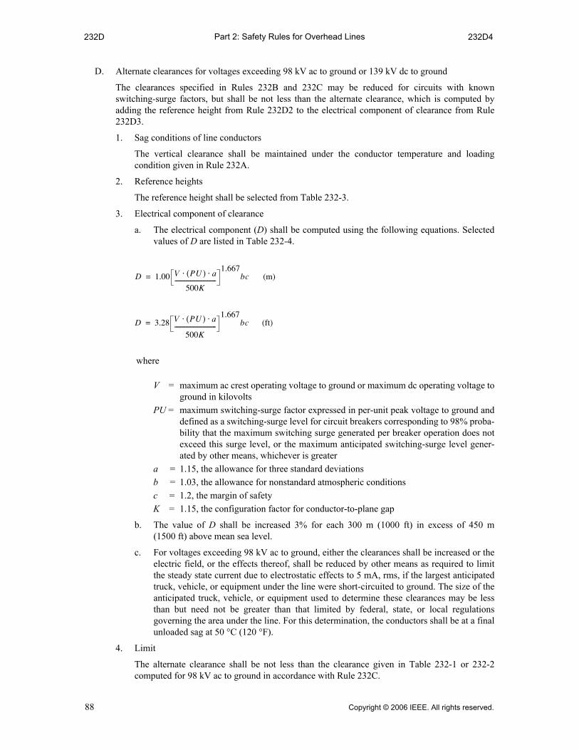
Part 2: Safety Rules for Overhead Lines232D 232D4
D. Alternate clearances for voltages exceeding 98 kV ac to ground or 139 kV dc to ground
The clearances specified in Rules 232B and 232C may be reduced for circuits with knownswitching-surge factors, but shall be not less than the alternate clearance, which is computed byadding the reference height from Rule 232D2 to the electrical component of clearance from Rule232D3.
1. Sag conditions of line conductors
The vertical clearance shall be maintained under the conductor temperature and loadingcondition given in Rule 232A.
2. Reference heights
The reference height shall be selected from Table 232-3.
3. Electrical component of clearance
a. The electrical component (D) shall be computed using the following equations. Selectedvalues of D are listed in Table 232-4.
where
V = maximum ac crest operating voltage to ground or maximum dc operating voltage toground in kilovolts
PU = maximum switching-surge factor expressed in per-unit peak voltage to ground anddefined as a switching-surge level for circuit breakers corresponding to 98% proba-bility that the maximum switching surge generated per breaker operation does notexceed this surge level, or the maximum anticipated switching-surge level gener-ated by other means, whichever is greater
a = 1.15, the allowance for three standard deviations b = 1.03, the allowance for nonstandard atmospheric conditions c = 1.2, the margin of safety K = 1.15, the configuration factor for conductor-to-plane gap
b. The value of D shall be increased 3% for each 300 m (1000 ft) in excess of 450 m(1500 ft) above mean sea level.
c. For voltages exceeding 98 kV ac to ground, either the clearances shall be increased or theelectric field, or the effects thereof, shall be reduced by other means as required to limitthe steady state current due to electrostatic effects to 5 mA, rms, if the largest anticipatedtruck, vehicle, or equipment under the line were short-circuited to ground. The size of theanticipated truck, vehicle, or equipment used to determine these clearances may be lessthan but need not be greater than that limited by federal, state, or local regulationsgoverning the area under the line. For this determination, the conductors shall be at a finalunloaded sag at 50 °C (120 °F).
4. Limit
The alternate clearance shall be not less than the clearance given in Table 232-1 or 232-2computed for 98 kV ac to ground in accordance with Rule 232C.
D 1.00 V PU( ) a⋅ ⋅
500K-----------------------------
1.667bc (m)=
D 3.28 V PU( ) a⋅ ⋅
500K-----------------------------
1.667bc (ft)=
88 Copyright © 2006 IEEE. All rights reserved.

Part 2: Safety Rules for Overhead LinesT-232-1(m) T-232-1(m)
mTable 232-1—
Vertical clearance of wires, conductors, and cables above ground, roadway, rail, or water surfaces2%
(Voltages are phase to ground for effectively grounded circuits and those other circuits where all ground faults are cleared by promptly de-energizing the faulted section, both initially and following subsequent breaker
operations. See the definitions section for voltages of other systems. See Rules 232B1, 232C1a, and 232D4.)
Nature of surface underneath wires,
conductors, or cables
Insulated
communication conductors and
cable; messengers;
overhead shield/surge-protection wires; grounded
guys; ungrounded
guys exposed to 0 to 300 V s h;
neutral conductors
meeting Rule 230E1; supply cables meeting
Rule 230C1(m)
Noninsulated communica--
tion conductors;
supply cables of 0 to 750 V meeting Rule
230C2 or 230C3
(m)
Supply cables over
750 V meeting
Rule 230C2 or 230C3;
open supply conductors,
0 to 750 V e;
unground-ed guys
exposed to over 300 V to 750 V g
(m)
Open supply
conductors, over 750 V to 22 kV;
unground-ed guys
exposed to 750 V to 22 kV g
(m)
Trolley and electrified railroad contact conductors and associated span
or
0 to 750 V
to ground
(m)
Over 750 V to
22 kV to
ground (m)
Where wires, conductors, or cables cross over or overhang
1. Track rails of railroads (except electrified railroads using overhead trolley conductors) w j 2@
7.2 7.3 7.5 8.1 6.7 r 6.7 r
2. Roads, streets, and other areas subject to truck traffic 2#
4.7 4.9 5.0 5.6 5.5 t 6.1 t
3. Driveways, parking lots, and alleys 2#
4.7 u f 4.9 u f 5.0 u 5.6 5.5 t 6.1 t
4. Other land traversed by vehicles, such as culti-vated, grazing, forest, orchard, etc. 2^
4.7 4.9 5.0 5.6 — —
5. Spaces and ways subject to pedestrians or restricted traffic only o
2.9 3.6 i 3.8 i 4.4 4.9 5.5
6. Water areas not suitable for sailboating or where sailboating is prohibited 2!
4.0 4.4 4.6 5.2 — —
7. Water areas suitable for sailboating including lakes, ponds, reservoirs, tidal waters, rivers, streams, and canals with an unobstructed surface area of k l ; 2) 2!
a. Less than 0.08 km2 5.3 5.5 5.6 6.2 — —
Copyright © 2006 IEEE. All rights reserved. 89

Part 2: Safety Rules for Overhead LinesT-232-1(m) T-232-1(m)
qWhere subways, tunnels, or bridges require it, less clearance above ground or rails than required by Table 232-1 maybe used locally. The trolley and electrified railroad contact conductor should be graded very gradually from theregular construction down to the reduced elevation.
wFor wires, conductors, or cables crossing over mine, logging, and similar railways that handle only cars lower thanstandard freight cars, the clearance may be reduced by an amount equal to the difference in height between thehighest loaded car handled and 6.1 m, but the clearance shall not be reduced below that required for street crossings.
eDoes not include neutral conductors meeting Rule 230E1.
rIn communities where 6.4 m has been established, this clearance may be continued if carefully maintained. Theelevation of the contact conductor should be the same in the crossing and next adjacent spans. (See Rule 225D2 forconditions that must be met where uniform height above rail is impractical.)
tIn communities where 4.9 m has been established for trolley and electrified railroad contact conductors 0 to 750 Vto ground, or 5.5 m for trolley and electrified railroad contact conductors exceeding 750 V, or where local conditionsmake it impractical to obtain in the clearance given in the table, these reduced clearances may be used if carefullymaintained.
yThis footnote not used in this edition.
b. Over 0.08 to 0.8 km2 7.8 7.9 8.1 8.7 — —
c. Over 0.8 to 8 km2 9.6 9.8 9.9 10.5 — —
d. Over 8 km2 11.4 11.6 11.7 12.3 — —
8. Established boat ramps and associated rigging areas; areas posted with sign(s) for rigging or launching sail boats
Clearance aboveground shall be 1.5 m greater than in 7 above, for the type of water areas served by the launching sites
Where wires, conductors, or cables run along and within the limits ofhighways or other road rights-of-way but do not overhang the roadway
9. Roads, streets, or alleys 4.7 2$ 4.9 5.0 5.6 5.5 t 6.1 t
10. Roads where it is unlikely that vehicles will be crossing under the line
4.1 a d 4.3 a 4.4 a 5.0 5.5 t 6.1 t
mTable 232-1— (continued)
Vertical clearance of wires, conductors, and cables above ground, roadway, rail, or water surfaces2%
(Voltages are phase to ground for effectively grounded circuits and those other circuits where all ground faults are cleared by promptly de-energizing the faulted section, both initially and following subsequent breaker
operations. See the definitions section for voltages of other systems. See Rules 232B1, 232C1a, and 232D4.)
Nature of surface underneath wires,
conductors, or cables
Insulated
communication conductors and
cable; messengers;
overhead shield/surge-protection wires; grounded
guys; ungrounded
guys exposed to 0 to 300 V s h;
neutral conductors
meeting Rule 230E1; supply cables meeting
Rule 230C1(m)
Noninsulated communica--
tion conductors;
supply cables of 0 to 750 V meeting Rule
230C2 or 230C3
(m)
Supply cables over
750 V meeting
Rule 230C2 or 230C3;
open supply conductors,
0 to 750 V e;
unground-ed guys
exposed to over 300 V to 750 V g
(m)
Open supply
conductors, over 750 V to 22 kV;
unground-ed guys
exposed to 750 V to 22 kV g
(m)
Trolley and electrified railroad contact conductors and associated span
or
0 to 750 V
to ground
(m)
Over 750 V to
22 kV to
ground (m)
90 Copyright © 2006 IEEE. All rights reserved.

Part 2: Safety Rules for Overhead LinesT-232-1(m) T-232-1(m)
uWhere the height of a residential building does not permit its service drop(s) to meet these values, the clearances overresidential driveways only may be reduced to the following:
(m)(a) Insulated supply service drops limited to 300 V to ground 3.8(b) Insulated drip loops of supply service drops limited to 300 V to ground 3.2(c) Supply service drops limited to 150 V to ground and meeting Rule 230C1 or 230C3 3.6(d) Drip loops only of service drops limited to 150 V to ground and meeting Rule 230C1 or 230C3 3.0 (e) Insulated communication service drops 3.5
iWhere the height of a residential building does not permit its service drop(s) to meet these values, the clearances maybe reduced to the following:
(m)(a) Insulated supply service drops limited to 300 V to ground 3.2(b) Insulated drip loops of supply service drops limited to 300 V to ground 3.2(c) Supply service drops limited to 150 V to ground and meeting Rule 230C1 or 230C3 3.0(d) Drip loops only of supply service drops limited to 150 V to ground and meeting Rule 230C1 or 230C3 3.0
oSpaces and ways subject to pedestrians or restricted traffic only are those areas where riders on horses or other largeanimals, vehicles, or other mobile units exceeding a total height of 2.45 m, are prohibited by regulation or permanentterrain configurations, or are otherwise not normally encountered nor reasonably anticipated.
aWhere a supply or communication line along a road is located relative to fences, ditches, embankments, etc., so thatthe ground under the line would not be expected to be traveled except by pedestrians, the clearances may be reducedto the following values:
(m)(a) Insulated communication conductor and communication cables 2.9(b) Conductors of other communication circuits 2.9(c) Supply cables of any voltage meeting Rule 230C1, supply cables limited to 150 V to ground
meeting Rule 230C2 or 230C3, and neutral conductors meeting Rule 230E1 2.9(d) Insulated supply conductors limited to 300 V to ground 3.8(e) Guys 2.9
sNo clearance from ground is required for anchor guys not crossing tracks, rails, streets, driveways, roads, orpathways.
dThis clearance may be reduced to 4.0 m for communication conductors and guys.fWhere this construction crosses over or runs along alleys, driveways, or parking lots not subject to truck traffic this
clearance may be reduced to 4.6 m.gUngrounded guys and ungrounded portions of span guys between guy insulators shall have clearances based on the
highest voltage to which they may be exposed due to a slack conductor or guy.h Anchor guys insulated in accordance with Rule 279 may have the same clearance as grounded guys. jAdjacent to tunnels and overhead bridges that restrict the height of loaded rail cars to less than 6.1 m, these clearances
may be reduced by the difference between the highest loaded rail car handled and 6.1 m, if mutually agreed to bythe parties at interest.
kFor controlled impoundments, the surface area and corresponding clearances shall be based upon the design high-water level.
lFor uncontrolled water flow areas, the surface area shall be that enclosed by its annual high-water mark. Clearancesshall be based on the normal flood level; if available, the 10-year flood level may be assumed as the normal floodlevel.
;The clearance over rivers, streams, and canals shall be based upon the largest surface area of any 1.6 km-longsegment that includes the crossing. The clearance over a canal, river, or stream normally used to provide access forsailboats to a larger body of water shall be the same as that required for the larger body of water.
2)Where an overwater obstruction restricts vessel height to less than the applicable reference height given in Table232-3, the required clearance may be reduced by the difference between the reference height and the overwaterobstruction height, except that the reduced clearance shall be not less than that required for the surface area on theline-crossing side of the obstruction.
2!Where the US Army Corps of Engineers, or the state, or surrogate thereof has issued a crossing permit, clearancesof that permit shall govern.
2@See Rule 234I for the required horizontal and diagonal clearances to rail cars. 2#For the purpose of this rule, trucks are defined as any vehicle exceeding 2.45 m in height. Areas not subject to truck
traffic are areas where truck traffic is not normally encountered nor reasonably anticipated. 2$Communication cables and conductors may have a clearance of 4.6 m where poles are back of curbs or other
deterrents to vehicular traffic.2% The clearance values shown in this table are computed by adding the applicable Mechanical and Electrical (M & E)
value of Table A-1 to the applicable Reference Component of Table A-2a of Appendix A.2^When designing a line to accommodate oversized vehicles, these clearance values shall be increased by the
difference between the known height of the oversized vehicle and 4.3 m.
Copyright © 2006 IEEE. All rights reserved. 91
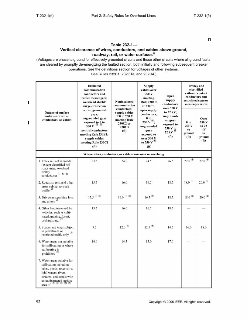
Part 2: Safety Rules for Overhead LinesT-232-1(ft) T-232-1(ft)
ftTable 232-1—
Vertical clearance of wires, conductors, and cables above ground, roadway, rail, or water surfaces2%
(Voltages are phase to ground for effectively grounded circuits and those other circuits where all ground faults are cleared by promptly de-energizing the faulted section, both initially and following subsequent breaker
operations. See the definitions section for voltages of other systems. See Rules 232B1, 232C1a, and 232D4.)
Nature of surface underneath wires,
conductors, or cables
Insulated communication conductors and
cable; messengers; overhead shield/surge-protection wires; grounded
guys; ungrounded guys
exposed to 0 to 300 V s h;
neutral conductors meeting Rule 230E1;
supply cables meeting Rule 230C1
(ft)
Noninsulated communication
conductors; supply cables of 0 to 750 V meeting Rule
230C2 or 230C3
(ft)
Supply cables over
750 V meeting
Rule 230C2 or 230C3;
open supply conductors,
0 to 750 V e;
ungrounded guys
exposed to over 300 V to 750 V g
(ft)
Open supply
conductors, over 750 V to 22 kV;
unground-ed guys
exposed to 750 V to 22 kV g
(ft)
Trolley and electrified
railroad contact conductors and
associated span or messenger wires
0 to750 V
to ground
(ft)
Over 750 Vto 22 kVto
ground(ft)
Where wires, conductors, or cables cross over or overhang
1. Track rails of railroads (except electrified rail-roads using overhead trolley conductors) w j 2@
23.5 24.0 24.5 26.5 22.0 r 22.0 r
2. Roads, streets, and other areas subject to truck traffic 2#
15.5 16.0 16.5 18.5 18.0 t 20.0 t
3. Driveways, parking lots, and alleys 2#
15.5 u f 16.0 u f 16.5 u 18.5 18.0 t 20.0 t
4. Other land traversed by vehicles, such as culti-vated, grazing, forest, orchards, etc. 2$
15.5 16.0 16.5 18.5 — —
5. Spaces and ways subject to pedestrians or restricted traffic only o
9.5 12.0 i 12.5 i 14.5 16.0 18.0
6. Water areas not suitable for sailboating or where sailboating is prohibited 2!
14.0 14.5 15.0 17.0 — —
7. Water areas suitable for sailboating including lakes, ponds, reservoirs, tidal waters, rivers, streams, and canals with an unobstructed surface area of k l ; 2) 2!
92 Copyright © 2006 IEEE. All rights reserved.
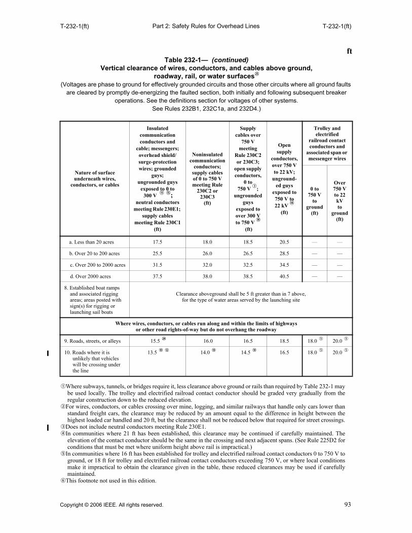
Part 2: Safety Rules for Overhead LinesT-232-1(ft) T-232-1(ft)
qWhere subways, tunnels, or bridges require it, less clearance above ground or rails than required by Table 232-1 maybe used locally. The trolley and electrified railroad contact conductor should be graded very gradually from theregular construction down to the reduced elevation.
wFor wires, conductors, or cables crossing over mine, logging, and similar railways that handle only cars lower thanstandard freight cars, the clearance may be reduced by an amount equal to the difference in height between thehighest loaded car handled and 20 ft, but the clearance shall not be reduced below that required for street crossings.
eDoes not include neutral conductors meeting Rule 230E1.rIn communities where 21 ft has been established, this clearance may be continued if carefully maintained. The
elevation of the contact conductor should be the same in the crossing and next adjacent spans. (See Rule 225D2 forconditions that must be met where uniform height above rail is impractical.)
tIn communities where 16 ft has been established for trolley and electrified railroad contact conductors 0 to 750 V toground, or 18 ft for trolley and electrified railroad contact conductors exceeding 750 V, or where local conditionsmake it impractical to obtain the clearance given in the table, these reduced clearances may be used if carefullymaintained.
yThis footnote not used in this edition.
a. Less than 20 acres 17.5 18.0 18.5 20.5 — —
b. Over 20 to 200 acres 25.5 26.0 26.5 28.5 — —
c. Over 200 to 2000 acres 31.5 32.0 32.5 34.5 — —
d. Over 2000 acres 37.5 38.0 38.5 40.5 — —
8. Established boat ramps and associated rigging areas; areas posted with sign(s) for rigging or launching sail boats
Clearance aboveground shall be 5 ft greater than in 7 above, for the type of water areas served by the launching site
Where wires, conductors, or cables run along and within the limits of highways or other road rights-of-way but do not overhang the roadway
9. Roads, streets, or alleys 15.5 2$ 16.0 16.5 18.5 18.0 t 20.0 t
10. Roads where it is unlikely that vehicles will be crossing under the line
13.5 a d 14.0 a 14.5 a 16.5 18.0 t 20.0 t
ftTable 232-1— (continued)
Vertical clearance of wires, conductors, and cables above ground, roadway, rail, or water surfaces2%
(Voltages are phase to ground for effectively grounded circuits and those other circuits where all ground faults are cleared by promptly de-energizing the faulted section, both initially and following subsequent breaker
operations. See the definitions section for voltages of other systems. See Rules 232B1, 232C1a, and 232D4.)
Nature of surface underneath wires,
conductors, or cables
Insulated communication conductors and
cable; messengers; overhead shield/surge-protection wires; grounded
guys; ungrounded guys
exposed to 0 to 300 V s h;
neutral conductors meeting Rule 230E1;
supply cables meeting Rule 230C1
(ft)
Noninsulated communication
conductors; supply cables of 0 to 750 V meeting Rule
230C2 or 230C3
(ft)
Supply cables over
750 V meeting
Rule 230C2 or 230C3;
open supply conductors,
0 to 750 V e;
ungrounded guys
exposed to over 300 V to 750 V g
(ft)
Open supply
conductors, over 750 V to 22 kV;
unground-ed guys
exposed to 750 V to 22 kV g
(ft)
Trolley and electrified
railroad contact conductors and
associated span or messenger wires
0 to750 V
to ground
(ft)
Over 750 Vto 22 kVto
ground(ft)
Copyright © 2006 IEEE. All rights reserved. 93

Part 2: Safety Rules for Overhead LinesT-232-1(ft) T-232-1(ft)
uWhere the height of a residential building does not permit its service drop(s) to meet these values, the clearances overresidential driveways only may be reduced to the following:
(ft) (a) Insulated supply service drops limited to 300 V to ground 12.5 (b) Insulated drip loops of supply service drops limited to 300 V to ground 10.5 (c) Supply service drops limited to 150 V to ground and meeting Rule 230C1 or 230C3 12.0 (d) Drip loops only of service drops limited to 150 V to ground and meeting Rule 230C1 or 230C3 10.0 (e) Insulated communication service drops 11.5
iWhere the height of a residential building does not permit its service drop(s) to meet these values, the clearances maybe reduced to the following:
(ft)(a) Insulated supply service drops limited to 300 V to ground 10.5 (b) Insulated drip loops of supply service drops limited to 300 V to ground 10.5 (c) Supply service drops limited to 150 V to ground and meeting Rule 230C1 or 230C3 10.0 (d) Drip loops only of supply service drops limited to 150 V to ground and meeting Rule 230C1 or 230C3 10.0
oSpaces and ways subject to pedestrians or restricted traffic only are those areas where riders on horses or other largeanimals, vehicles, or other mobile units exceeding a total height of 8 ft are prohibited by regulation or permanentterrain configurations, or are otherwise not normally encountered nor reasonably anticipated.
aWhere a supply or communication line along a road is located relative to fences, ditches, embankments, etc., so thatthe ground under the line would not be expected to be traveled except by pedestrians, the clearances may be reducedto the following values:
(ft) (a) Insulated communication conductor and communication cables. 9.5 (b) Conductors of other communication circuits 9.5 (c) Supply cables of any voltage meeting Rule 230C1, supply cables limited to 150 Vto ground
meeting Rule 230C2 or 230C3, and neutral conductors meeting Rule 230E1 9.5 (d) Insulated supply conductors limited to 300 V to ground 12.5 (e) Guys 9.5
sNo clearance from ground is required for anchor guys not crossing tracks, rails, streets, driveways, roads, orpathways.
dThis clearance may be reduced to 13 ft for communication conductors and guys.fWhere this construction crosses over or runs along alleys, driveways, or parking lots not subject to truck traffic this
clearance may be reduced to 15 ft.gUngrounded guys and ungrounded portions of span guys between guy insulators shall have clearances based on the
highest voltage to which they may be exposed due to a slack conductor or guy.hAnchor guys insulated in accordance with Rule 279 may have the same clearance as grounded guys. jAdjacent to tunnels and overhead bridges that restrict the height of loaded rail cars to less than 20 ft, these clearances
may be reduced by the difference between the highest loaded rail car handled and 20 ft, if mutually agreed to by theparties at interest.
kFor controlled impoundments, the surface area and corresponding clearances shall be based upon the design high-water level.
lFor uncontrolled water flow areas, the surface area shall be that enclosed by its annual high-water mark. Clearancesshall be based on the normal flood level; if available, the 10-year flood level may be assumed as the normal floodlevel.
;The clearance over rivers, streams, and canals shall be based upon the largest surface area of any 1-mi-long segmentthat includes the crossing. The clearance over a canal, river, or stream normally used to provide access for sailboatsto a larger body of water shall be the same as that required for the larger body of water.
2)Where an overwater obstruction restricts vessel height to less than the applicable reference height given inTable 232-3, the required clearance may be reduced by the difference between the reference height and theoverwater obstruction height, except that the reduced clearance shall be not less than that required for the surfacearea on the line-crossing side of the obstruction.
2!Where the US Army Corps of Engineers, or the state, or surrogate thereof has issued a crossing permit, clearancesof that permit shall govern.
2@See Rule 234I for the required horizontal and diagonal clearances to rail cars. 2#For the purpose of this rule, trucks are defined as any vehicle exceeding 8 ft in height. Areas not subject to truck
traffic are areas where truck traffic is not normally encountered nor reasonably anticipated.2$Communication cables and conductors may have a clearance of 15 ft where poles are back of curbs or other
deterrents to vehicular traffic. 2%The clearance values shown in this table are computed by adding the applicable Mechanical and Electrical (M & E)
value of Table A-1 to the applicable Reference Component of Table A-2a of Appendix A.2^When designing a line to accommodate oversized vehicles, these clearance values shall be increased by the
difference between the known height of the oversized vehicle and 14 ft.
94 Copyright © 2006 IEEE. All rights reserved.
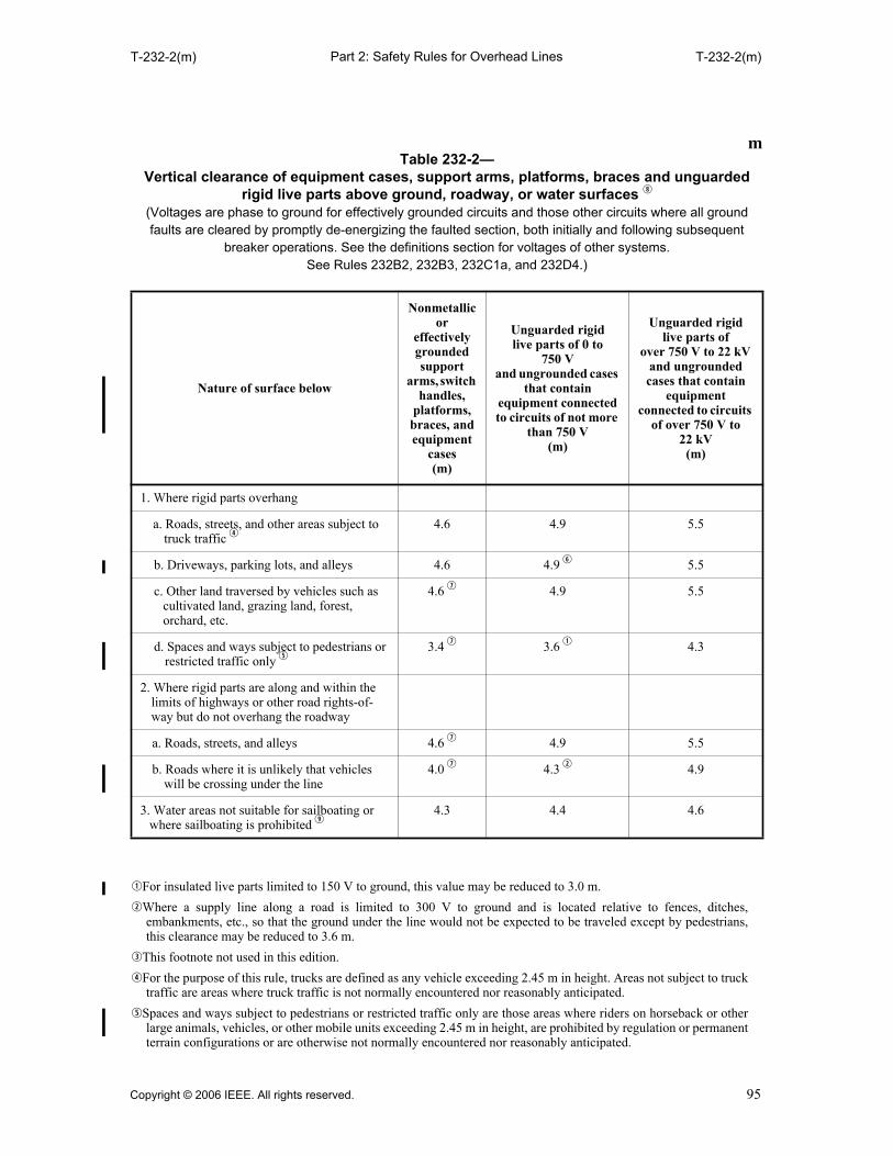
Part 2: Safety Rules for Overhead LinesT-232-2(m) T-232-2(m)
qFor insulated live parts limited to 150 V to ground, this value may be reduced to 3.0 m.
wWhere a supply line along a road is limited to 300 V to ground and is located relative to fences, ditches,embankments, etc., so that the ground under the line would not be expected to be traveled except by pedestrians,this clearance may be reduced to 3.6 m.
eThis footnote not used in this edition.
rFor the purpose of this rule, trucks are defined as any vehicle exceeding 2.45 m in height. Areas not subject to trucktraffic are areas where truck traffic is not normally encountered nor reasonably anticipated.
tSpaces and ways subject to pedestrians or restricted traffic only are those areas where riders on horseback or otherlarge animals, vehicles, or other mobile units exceeding 2.45 m in height, are prohibited by regulation or permanentterrain configurations or are otherwise not normally encountered nor reasonably anticipated.
mTable 232-2—
Vertical clearance of equipment cases, support arms, platforms, braces and unguarded rigid live parts above ground, roadway, or water surfaces i
(Voltages are phase to ground for effectively grounded circuits and those other circuits where all ground faults are cleared by promptly de-energizing the faulted section, both initially and following subsequent
breaker operations. See the definitions section for voltages of other systems. See Rules 232B2, 232B3, 232C1a, and 232D4.)
Nature of surface below
Nonmetallic or
effectively grounded support
arms, switch handles,
platforms, braces, and equipment
cases (m)
Unguarded rigid live parts of 0 to
750 Vand ungrounded cases
that contain equipment connected to circuits of not more
than 750 V(m)
Unguarded rigid live parts of
over 750 V to 22 kV and ungrounded cases that contain
equipment connected to circuits
of over 750 V to 22 kV
(m)
1. Where rigid parts overhang
a. Roads, streets, and other areas subject to truck traffic r
4.6 4.9 5.5
b. Driveways, parking lots, and alleys 4.6 4.9 y 5.5
c. Other land traversed by vehicles such as cultivated land, grazing land, forest, orchard, etc.
4.6 u 4.9 5.5
d. Spaces and ways subject to pedestrians or restricted traffic only t
3.4 u 3.6 q 4.3
2. Where rigid parts are along and within the limits of highways or other road rights-of-way but do not overhang the roadway
a. Roads, streets, and alleys 4.6 u 4.9 5.5
b. Roads where it is unlikely that vehicles will be crossing under the line
4.0 u 4.3 w 4.9
3. Water areas not suitable for sailboating or where sailboating is prohibited o
4.3 4.4 4.6
Copyright © 2006 IEEE. All rights reserved. 95

Part 2: Safety Rules for Overhead LinesT-232-2(m) T-232-2(ft)
yThis clearance may be reduced to the following values for driveways, parking lots, and alleys not subject to trucktraffic:
(m)(a) Insulated live parts limited to 300 V to ground 3.6(b) Insulated live parts limited to 150 V to ground 3.0
uEffectively grounded switch handles and supply or communication equipment cases (such as fire alarm boxes,control boxes, communication terminals, meters or similar equipment cases) may be mounted at a lower level foraccessibility, provided such cases do not unduly obstruct a walkway.NOTE: See also Rule 234J2c.
iThe clearance values shown in this table are computed by adding the applicable Mechanical and Electrical (M & E)value of Table A-1 to the applicable Reference Component of Table A-2a of Appendix A.
oWhere the US Army Corps of Engineers, or the state, or surrogate thereof has issued a crossing permit, clearancesof that permit shall govern.
ftTable 232-2—
Vertical clearance of equipment cases, support arms, platforms, braces and unguarded rigid live parts above ground, roadway, or water surfaces
i
(Voltages are phase to ground for effectively grounded circuits and those other circuits where all ground faults are cleared by promptly de-energizing the faulted section, both initially and following subsequent
breaker operations. See the definitions section for voltages of other systems. See Rules 232B2, 232B3, 232C1a, and 232D4.)
Nature of surface below
Nonmetallic or effectively
grounded support
arms, switch handles,
platforms, braces, and equipment
cases(ft)
Unguarded rigid live parts of 0 to 750 V and ungrounded cases that
contain equipment connected to circuits
of not more than 750 V
(ft)
Unguarded rigid live parts of over 750 V to
22 kV and ungrounded cases
that contain equipment connected
to circuits of over 750 V to 22 kV
(ft)
1. Where rigid parts overhang
a. Roads, streets, and other areas subject to truck traffic r
15.0 16.0 18.0
b. Driveways, parking lots, and alleys 15.0 16.0 y 18.0
c. Other land traversed by vehicles such as cultivated land, grazing land, forest, orchard, etc.
15.0 u 16.0 18.0
d. Spaces and ways subject to pedestrians or restricted traffic only t
11.0 u 12.0 q 14.0
2. Where rigid parts are along and within the limits of highways or other road rights-of-way but do not overhang the roadway
a. Roads, streets, and alleys 15.0 u 16.0 18.0
b. Roads where it is unlikely that vehicles will be crossing under the line
13.0 u 14.0 w 16.0
3. Water areas not suitable for sailboating or where sailboating is prohibited o
14.0 14.5 15.0
96 Copyright © 2006 IEEE. All rights reserved.

Part 2: Safety Rules for Overhead LinesT-232-2(ft) T-232-3
qFor insulated live parts limited to 150 V to ground, this value may be reduced to 10 ft.wWhere a supply line along a road is limited to 300 V to ground and is located relative to fences, ditches,
embankments, etc., so that the ground under the line would not be expected to be traveled except by pedestrians,this clearance may be reduced to 12 ft.
eThis footnote not used in this edition.rFor the purpose of this rule, trucks are defined as any vehicle exceeding 8 ft in height. Areas not subject to truck
traffic are areas where truck traffic is not normally encountered nor reasonably anticipated.tSpaces and ways subject to pedestrians or restricted traffic only are those areas where riders on horseback or other
large animals, vehicles, or other mobile units exceeding 8 ft in height, are prohibited by regulation or permanentterrain configurations or are otherwise not normally encountered nor reasonably anticipated.
yThis clearance may be reduced to the following values for driveways, parking lots, and alleys not subject to trucktraffic:
(ft)(a) Insulated live parts limited to 300 V to ground 12(b) Insulated live parts limited to 150 V to ground 10
uEffectively grounded switch handles and supply or communication equipment cases (such as fire alarm boxes,control boxes, communication terminals, meters, or similar equipment cases) may be mounted at a lower level foraccessibility, provided such cases do not unduly obstruct a walkway.NOTE: See also Rule 234J2c.
iThe clearance values shown in this table are computed by adding the applicable Mechanical and Electrical (M & E)value of Table A-1 to the applicable Reference Component of Table A-2a of Appendix A.
oWhere the US Army Corps of Engineers, or the state, or surrogate thereof has issued a crossing permit, clearancesof that permit shall govern.
qSee Rule 234I for the required horizontal and diagonal clearances to rail cars. wSpaces and ways subject to pedestrians or restricted traffic only are those areas where riders on horseback or other
large animals, vehicles, or other mobile units exceeding 2.45 m (8 ft) in height, are prohibited by regulation orpermanent terrain configurations or are otherwise not normally encountered nor reasonably anticipated.
eFor controlled impoundments, the surface area and corresponding clearances shall be based upon the design high-water level. For other waters, the surface area shall be that enclosed by its annual high-water mark, and clearancesshall be based on the normal flood level. The clearances over rivers, streams, and canals shall be based upon thelargest surface area of any 1600 m (1 mi) long segment that includes the crossing. The clearance over a canal or
Table 232-3—Reference heights (See Rule 232D2.)
Nature of surface underneath lines (m) (ft)
a. Track rails of railroads (except electrified railroads using overhead trolley conductors) q 6.7 22
b. Streets, alleys, roads, driveways, and parking lots 4.3 14
c. Spaces and ways subject to pedestrians or restricted traffic only w 3.0 10
d. Other land, such as cultivated, grazing, forest, or orchard, that is traversed by vehicles 4.3 14
e. Water areas not suitable for sailboating or where sailboating is prohibited 3.8 12.5
f. Water areas suitable for sailboating including lakes, ponds, reservoirs, tidal waters, rivers, streams, and canals with unobstructed surface area e r
(1) Less than 0.08 km2 (20 acres) 4.9 16
(2) Over 0.08 to 0.8 km2 (20 to 200 acres) 7.3 24
(3) Over 0.8 to 8 km2 (200 to 2000 acres) 9.0 30
(4) Over 8 km2 (2000 acres) 11.0 36
g. In public or private land and water areas posted for rigging or launching sailboats, the reference height shall be 1.5 m (5 ft) greater than in f above, for the type of water areas serviced by the launching site
Copyright © 2006 IEEE. All rights reserved. 97
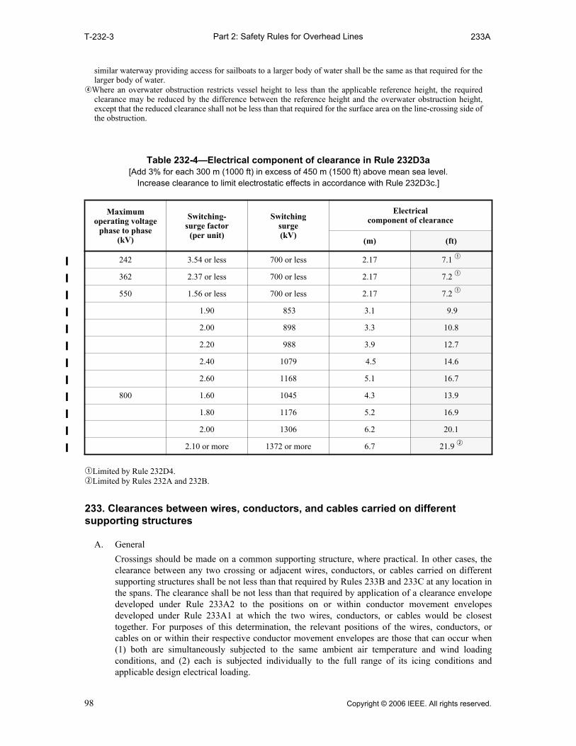
Part 2: Safety Rules for Overhead LinesT-232-3 233A
similar waterway providing access for sailboats to a larger body of water shall be the same as that required for thelarger body of water.
rWhere an overwater obstruction restricts vessel height to less than the applicable reference height, the requiredclearance may be reduced by the difference between the reference height and the overwater obstruction height,except that the reduced clearance shall not be less than that required for the surface area on the line-crossing side ofthe obstruction.
qLimited by Rule 232D4.wLimited by Rules 232A and 232B.
233. Clearances between wires, conductors, and cables carried on different supporting structures
A. General
Crossings should be made on a common supporting structure, where practical. In other cases, theclearance between any two crossing or adjacent wires, conductors, or cables carried on differentsupporting structures shall be not less than that required by Rules 233B and 233C at any location inthe spans. The clearance shall be not less than that required by application of a clearance envelopedeveloped under Rule 233A2 to the positions on or within conductor movement envelopesdeveloped under Rule 233A1 at which the two wires, conductors, or cables would be closesttogether. For purposes of this determination, the relevant positions of the wires, conductors, orcables on or within their respective conductor movement envelopes are those that can occur when(1) both are simultaneously subjected to the same ambient air temperature and wind loadingconditions, and (2) each is subjected individually to the full range of its icing conditions andapplicable design electrical loading.
Table 232-4—Electrical component of clearance in Rule 232D3a [Add 3% for each 300 m (1000 ft) in excess of 450 m (1500 ft) above mean sea level.
Increase clearance to limit electrostatic effects in accordance with Rule 232D3c.]
Maximum operating voltage
phase to phase (kV)
Switching-surge factor
(per unit)
Switching surge (kV)
Electrical component of clearance
(m) (ft)
242 3.54 or less 700 or less 2.17 7.1 q
362 2.37 or less 700 or less 2.17 7.2 q
550 1.56 or less 700 or less 2.17 7.2 q
1.90 853 3.1 9.9
2.00 898 3.3 10.8
2.20 988 3.9 12.7
2.40 1079 4.5 14.6
2.60 1168 5.1 16.7
800 1.60 1045 4.3 13.9
1.80 1176 5.2 16.9
2.00 1306 6.2 20.1
2.10 or more 1372 or more 6.7 21.9 w
98 Copyright © 2006 IEEE. All rights reserved.

Part 2: Safety Rules for Overhead Lines233A1 233C1
Figure 233-1 is a graphical illustration of the application of Rule 233A. Alternate methods thatassure compliance with these rules may be used.
1. Conductor movement envelope
a. Development
The conductor movement envelope shall be developed from the locus of the mostdisplaced conductor positions defined below and shown in Figure 233-2:
(1) 15 °C (60 °F), no wind displacement, at both initial unloaded and final unloaded sag(conductor positions A and C).
(2) With the wire, conductor, or cable displaced from rest by a 290 Pa (6 lb/ft2) wind atboth initial and final sag at 15 °C (60 °F). The displacement of the wire, conductor, orcable shall include deflection of suspension insulators and flexible structures(conductor positions B and D).
EXCEPTION: Where the entire span is so close to a building, terrain feature, or other obstacleas to be sheltered from the wind flowing across the line in either direction, the wind pressuremay be reduced to a 190 Pa (4 lb/ft2) wind. Trees are not considered to shelter a line.
(3) Final sag at one of the following loading conditions, whichever produces the largestsag (conductor position E):
(a) 50 °C (120 °F), no wind displacement,
(b) The maximum conductor temperature for which the line is designed to operate, ifgreater than 50 °C (120 °F), with no wind displacement, or
(c) 0 °C (32 °F), no wind displacement, with radial thickness of ice, if any, specifiedin Table 230-1 for the zone concerned.
b. Sag increase
No sag increase for either high operating temperatures or ice loading is required for trolleyand electrified railroad contact conductors. Rule 233A1a(3) does not apply to theseconductors.
2. Clearance envelope
The clearance envelope shown in Figure 233-3 shall be determined by the horizontal clearance(H) required by Rule 233B and the vertical clearance (V) required by Rule 233C.
B. Horizontal clearance
1. Clearance requirements
The horizontal clearance between crossing or adjacent wires, conductors, or cables carried ondifferent supporting structures shall be not less than 1.50 m (5 ft). For voltages between thewires, conductors, or cables exceeding 22 kV, additional clearance of 10 mm (0.4 in) per kVover 22 kV shall be provided.
EXCEPTION: The horizontal clearance between anchor guys of different supporting structures may bereduced to 150 mm (6 in) and may be reduced to 600 mm (2 ft) between other guys, span wires, andneutral conductors meeting Rule 230E1.
2. Alternate clearances for voltages exceeding 98 kV ac to ground or 139 kV dc to ground
The clearances specified in Rule 233B1 may be reduced for circuits with known switching-surge factors, but shall be not less than the alternate clearance derived from the computationsrequired in Rules 235B3a and 235B3b.
C. Vertical clearance
1. Clearance requirements
The vertical clearance between any crossing or adjacent wires, conductors, or cables carried ondifferent supporting structures shall be not less than that shown in Table 233-1.
EXCEPTION: No vertical clearance is required between wires, conductors, or cables that are electricallyinterconnected at the crossing.
Copyright © 2006 IEEE. All rights reserved. 99
Part 2: Safety Rules for Overhead Lines233C2 233C3b(1)
2. Voltages exceeding 22 kV
a. The clearance given in Table 233-1 shall be increased by the sum of the following: For theupper-level conductors between 22 and 470 kV, the clearance shall be increased at the rateof 10 mm (0.4 in) per kV in excess of 22 kV. For the lower-level conductors exceeding22 kV, the additional clearance shall be computed at the same rate. For voltages exceeding470 kV, the clearance shall be determined by the method given in Rule 233C3. The addi-tional clearance shall be computed using the maximum operating voltage if above 50 kVand nominal voltage if below 50 kV.
EXCEPTION: For voltages exceeding 98 kV ac to ground or 139 kV dc to ground, clearances lessthan those required above are permitted for systems with known switching-surge factors. (See Rule233C3.)
b. For voltages exceeding 50 kV, the additional clearance specified in Rule 233C2a shall beincreased 3% for each 300 m (1000 ft) in excess of 1000 m (3300 ft) above mean sealevel.
3. Alternate clearances for voltage exceeding 98 kV ac to ground or 139 kV dc to ground
The clearances specified in Rules 233C1 and 233C2 may be reduced where the higher-voltagecircuit has a known switching-surge factor, but shall be not less than the alternate clearance,which is computed by adding the reference height from Rule 233C3a to the electricalcomponent of clearance from Rule 233C3b. For these computations, communicationconductors and cables, guys, messengers, neutral conductors meeting Rule 230E1, and supplycables meeting Rule 230C1 shall be considered at zero voltage.
a. Reference heights
The reference height shall be selected from Table 233-3.
b. Electrical component of clearance
(1) The electrical component (D) shall be computed using the following equations.Selected values of D are listed in Table 233-2.
where
VH = higher-voltage circuit maximum ac crest operating voltage to ground ormaximum dc operating voltage to ground in kilovolts
VL = lower-voltage circuit maximum ac crest operating voltage to ground or max-imum dc operating voltage to ground in kilovolts
PU = higher-voltage circuit maximum switching-surge factor expressed in per-unitpeak voltage to ground and defined as a switching-surge level for circuitbreakers corresponding to 98% probability that the maximum switchingsurge generated per breaker operation does not exceed this surge level, or themaximum anticipated switching-surge level generated by other means,whichever is greater
a = 1.15, the allowance for three standard deviations b = 1.03, the allowance for nonstandard atmospheric conditions c = 1.2, the margin of safety K = 1.4, the configuration factor for conductor-to-conductor gap
D 1.00VH[ PU( ) VL+ ]a⋅
500K--------------------------------------------------
1.667bc m( )=
D 3.28 V H[ PU( ) V L+ ]a⋅
500K-----------------------------------------------
1.667bc ft( )=
100 Copyright © 2006 IEEE. All rights reserved.
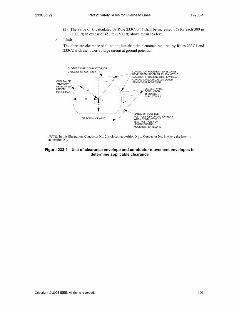
Part 2: Safety Rules for Overhead Lines233C3b(2) F-233-1
(2) The value of D calculated by Rule 233C3b(1) shall be increased 3% for each 300 m(1000 ft) in excess of 450 m (1500 ft) above mean sea level.
c. Limit
The alternate clearance shall be not less than the clearance required by Rules 233C1 and233C2 with the lower-voltage circuit at ground potential.
V
H
H
X1X2
CLOSEST WIRE, CONDUCTOR, OR
CABLE OF CIRCUIT NO. 1 CONDUCTOR MOVEMENT ENVELOPESDEVELOPED UNDER RULE 233AI AT THELOCATION IN THE LINE WHERE WIRES,CONDUCTORS, OR CABLES COULDBE CLOSEST TOGETHER
CLOSEST WIRE,
OR CABLE OF
RANGE OF POSSIBLE POSITIONS OF CONDUCTOR NO. 1WHEN CONDUCTOR NO. 1IS AT POSITION X ONITS CONDUCTORMOVEMENT ENVELOPE
DIRECTION OF WIND
CONDUCTOR,
CIRCUIT NO. 2
CLEARANCEENVELOPE DEVELOPEDUNDERRULE 233A2
NOTE: In this illustration, Conductor No. 2 is closest at position X2 to Conductor No. 1, where the latter isat position X1.
Figure 233-1—Use of clearance envelope and conductor movement envelopes to determine applicable clearance
Copyright © 2006 IEEE. All rights reserved. 101

Part 2: Safety Rules for Overhead LinesF-233-2(m) F-233-2(m)
qThe direction of the wind shall be that which produces the minimum distance between conductors. The displacementof the wires, conductors, or cables includes the deflection of suspension insulators and flexible structures.
wWhere the entire span is so close to a building, terrain feature, or other obstacle as to be sheltered from the windflowing across the line in either direction, the wind pressure may be reduced to a 190 Pa wind. Trees are notconsidered to shelter a line.
ePoint E shall be determined by whichever of the conditions described under E1 and E2 produces the greatest sag.rLine D–E shall be considered to be straight unless the actual concavity characteristics are known.tWhen one conductor movement envelope is lower than that of the other conductor, the lower envelope shall be
developed with points A, B, C, and D at a conductor temperature equal to the ambient temperature used indetermining E of the upper conductor movement envelope.
Point Conductor temperature Sag Ice loading Wind displacement q
A 15 °C t Initial None None
B 15 °C t Initial None 290 Pa w
C 15 °C t Final None None
D 15 °C t Final None 290 Pa w
E1 e r The greater of 50 °C or maxi-
mum operating temperatureFinal None None
E2 e r 0 °C Final As applicable None
CL
AB
D
C
E
DIRECTION OF WIND
CONDUCTOR
MOVEMENT
ENVELOPE
Figure 233-2—Conductor movement envelope
m
102 Copyright © 2006 IEEE. All rights reserved.

Part 2: Safety Rules for Overhead LinesF-233-2(ft) F-233-2(ft)
qThe direction of the wind shall be that which produces the minimum distance between conductors. The displacementof the wires, conductors, or cables includes the deflection of suspension insulators and flexible structures.
wWhere the entire span is so close to a building, terrain feature, or other obstacle as to be sheltered from the windflowing across the line in either direction, the wind pressure may be reduced to a 4 lb/ft2 wind. Trees are notconsidered to shelter a line.
ePoint E shall be determined by whichever of the conditions described under E1 and E2 produces the greatest sag.rLine D–E shall be considered to be straight unless the actual concavity characteristics are known.tWhen one conductor movement envelope is lower than that of the other conductor, the lower conductor envelope
shall be developed with points A, B, C, and D at a conductor temperature equal to the ambient temperature used indetermining E of the upper conductor movement envelope.
Point Conductor temperature Sag Ice loading Wind displacement q
A 60 °F t Initial None None
B 60 °F t Initial None 6 lb/ft2 w
C 60 °F t Final None None
D 60 °F t Final None 6 lb/ft2 w
E1 e r The greater of 120 °F or maxi-mum operating temperature
Final None None
E2 e r 32 °F Final As applicable None
CL
AB
D
C
E
DIRECTION OF WIND
CONDUCTOR
MOVEMENT
ENVELOPE
Figure 233-2—Conductor movement envelope
ft
Copyright © 2006 IEEE. All rights reserved. 103

Part 2: Safety Rules for Overhead LinesF-233-3 T-233-1(m)
mTable 233-1—
Vertical clearance between wires, conductors, and cables carried on different supporting structures
(Voltages are phase to ground for effectively grounded circuits and those other circuits where all ground faults are cleared by promptly de-energizing the faulted section, both initially and following subsequent
breaker operations. See the definitions section for voltages of other systems. See Rules 233C1 and 233C2a.)
Lower level
Upper level
Effectively grounded
communication guys,u span
wires and messengers,
communication conductors and
cables(m)
Effectively grounded supply
guys,u span wires and messengers,
neutral conductors meeting Rule 230E1, and
overhead shield/surge-protection
wires (m)
Supply cables meeting Rule 230C1, and
supply cables of 0 to 750 V meeting Rule
230C2 or 230C3
(m)
Open supply
conductors 0 to 750 V,y and supply cables over
750 V meeting
Rule 230C2 or 230C3
(m)
Open supply
conductors over 750 V to 22 kV
(m)
1.Effectively grounded supply guys, u span wires and messengers, neutral conductors meeting Rule 230E1, and overhead shield/surge-protection wires
0.60 q w 0.60 q w 0.60 w 0.60 0.60
2.Effectively grounded communication guys, u span wires and messen-gers; communication conductors and cables
0.60 q w 0.60 q 0.60 1.20 i 1.50 t
Figure 233-3—Clearance envelope
CLOSEST ALLOWABLE POSITION
OF CONDUCTOR NO 2
H
VVCONDUCTOR NO 1
H
V
VH
H
CONDUCTOR NO 1
CONDUCTOR NO 1
ifH>V
ifH=V
ifH<V
104 Copyright © 2006 IEEE. All rights reserved.

Part 2: Safety Rules for Overhead LinesT-233-1(m) T-233-1(m)
qNo clearance is specified between guys or span wires that are electrically interconnected. wThe clearance of communication conductors and their guy, span, and messenger wires from each other in locations
where no other classes of conductors are involved may be reduced by mutual consent of the parties concerned,except for fire-alarm conductors and conductors used in the operation of railroads.
eTrolley and electrified railroad contact conductors of more than 750 V should have at least 1.80 m of clearance. Thisclearance should also be provided over lower-voltage trolley and electrified railroad contact conductors unless thecrossover conductors are beyond reach of a trolley pole leaving the trolley-contact conductor or are suitablyprotected against damage from trolley poles leaving the trolley-contact conductor.
rTrolley and electrified railroad feeders are exempt from this clearance requirement for contact conductors if they areof the same nominal voltage and of the same system.
tThis clearance may be reduced to 1.20 m where supply conductors of 750 V to 8.7 kV cross a communication linemore than 6 ft horizontally from a communications structure.
y Does not include neutral conductors meeting Rule 230E1.uThese clearances may be reduced by not more than 25% to a guy insulator, provided that full clearance is maintained
to its metallic end fittings and the guy wires. The clearance to an insulated section of a guy between two insulatorsmay be reduced by not more than 25% provided that full clearance is maintained to the uninsulated portion of theguy.
iThis clearance may be reduced to 0.60 m for supply service drops.oIn general, this type of crossing is not recommended.
3. Supply cables meeting Rule 230C1, and supply cables of 0 to 750 V meeting Rule 230C2 or 230C3
0.60 0.60 0.60 0.60 0.60
4. Open supply conductors, 0 to 750 V y; supply cables over 750 V meet-ing Rule 230C2 or 230C3
1.20 o 0.60 0.60 0.60 0.60
5. Open supply conductors, 750 V to 22 kV
1.50 t o 0.60 0.60 o 0.60 o 0.60
6. Trolley and electrified railroad contact conduc-tors and associated span and messenger wires
1.20 e 1.20 e 1.20 e 1.20 e r 1.80
mTable 233-1— (continued)
Vertical clearance between wires, conductors, and cables carried on different supporting structures
(Voltages are phase to ground for effectively grounded circuits and those other circuits where all ground faults are cleared by promptly de-energizing the faulted section, both initially and following subsequent
breaker operations. See the definitions section for voltages of other systems. See Rules 233C1 and 233C2a.)
Lower level
Upper level
Effectively grounded
communication guys,u span
wires and messengers,
communication conductors and
cables(m)
Effectively grounded supply
guys,u span wires and messengers,
neutral conductors meeting Rule 230E1, and
overhead shield/surge-protection
wires (m)
Supply cables meeting Rule 230C1, and
supply cables of 0 to 750 V meeting Rule
230C2 or 230C3
(m)
Open supply
conductors 0 to 750 V,y and supply cables over
750 V meeting
Rule 230C2 or 230C3
(m)
Open supply
conductors over 750 V to 22 kV
(m)
Copyright © 2006 IEEE. All rights reserved. 105
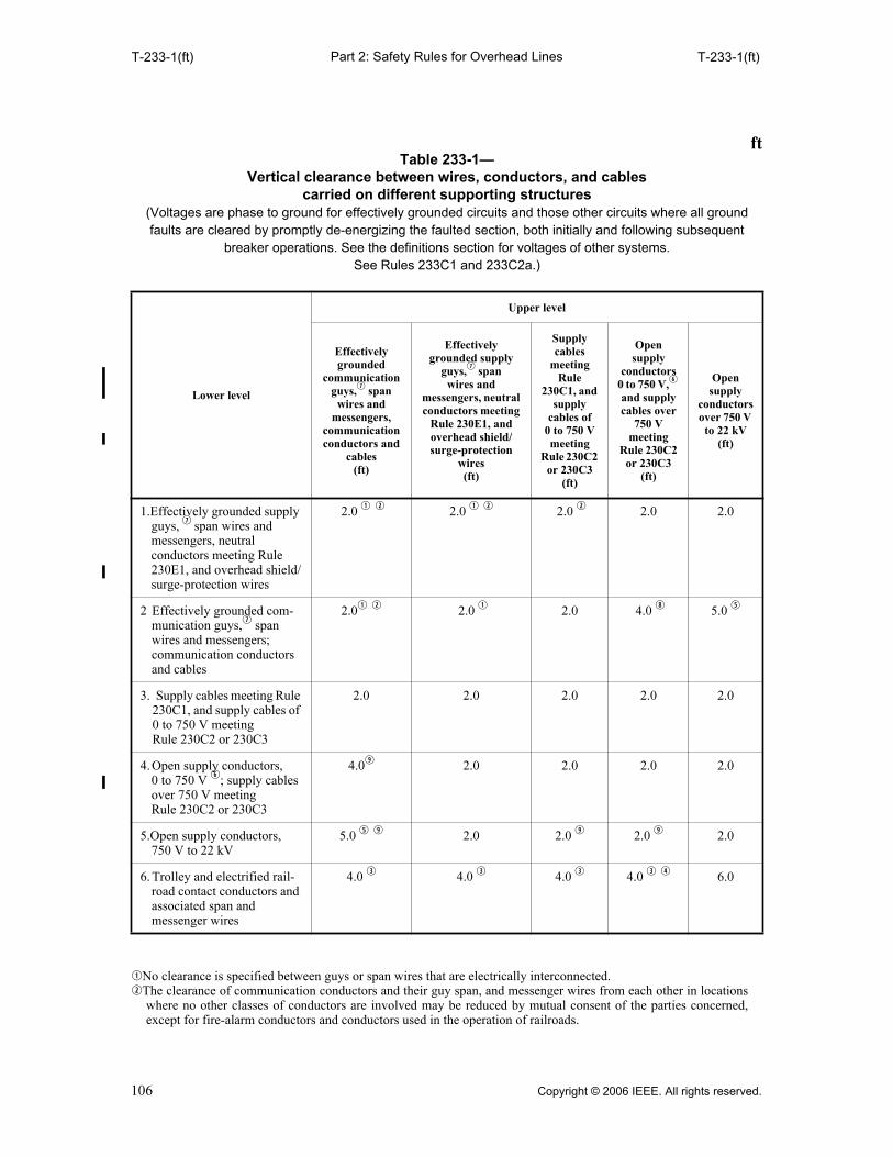
Part 2: Safety Rules for Overhead Lines
T-233-1(ft) T-233-1(ft)
qNo clearance is specified between guys or span wires that are electrically interconnected. wThe clearance of communication conductors and their guy span, and messenger wires from each other in locations
where no other classes of conductors are involved may be reduced by mutual consent of the parties concerned,except for fire-alarm conductors and conductors used in the operation of railroads.
ftTable 233-1—
Vertical clearance between wires, conductors, and cables carried on different supporting structures
(Voltages are phase to ground for effectively grounded circuits and those other circuits where all ground faults are cleared by promptly de-energizing the faulted section, both initially and following subsequent
breaker operations. See the definitions section for voltages of other systems. See Rules 233C1 and 233C2a.)
Lower level
Upper level
Effectively grounded
communication guys,u span
wires and messengers,
communication conductors and
cables(ft)
Effectively grounded supply
guys,u spanwires and
messengers, neutral conductors meeting
Rule 230E1, and overhead shield/surge-protection
wires (ft)
Supply cables
meeting Rule
230C1, and supply
cables of 0 to 750 V meeting
Rule 230C2 or 230C3
(ft)
Open supply
conductors 0 to 750 V,y and supply cables over
750 V meeting
Rule 230C2 or 230C3
(ft)
Open supply
conductors over 750 V to 22 kV
(ft)
1.Effectively grounded supply guys, u span wires and messengers, neutral conductors meeting Rule 230E1, and overhead shield/surge-protection wires
2.0 q w 2.0 q w 2.0 w 2.0 2.0
2 Effectively grounded com-munication guys,u span wires and messengers; communication conductors and cables
2.0q w 2.0 q 2.0 4.0 i 5.0 t
3. Supply cables meeting Rule 230C1, and supply cables of 0 to 750 V meeting Rule 230C2 or 230C3
2.0 2.0 2.0 2.0 2.0
4.Open supply conductors, 0 to 750 V y; supply cables over 750 V meeting Rule 230C2 or 230C3
4.0o 2.0 2.0 2.0 2.0
5.Open supply conductors, 750 V to 22 kV
5.0 t o 2.0 2.0 o 2.0 o 2.0
6. Trolley and electrified rail-road contact conductors and associated span and messenger wires
4.0 e 4.0 e 4.0 e 4.0 e r 6.0
106 Copyright © 2006 IEEE. All rights reserved.

Part 2: Safety Rules for Overhead Lines
T
-233-1(ft) T-233-2(m)
eTrolley and electrified railroad contact conductors of more than 750 V should have at least 6 ft of clearance. Thisclearance should also be provided over lower-voltage trolley and electrified railroad contact conductors unless thecrossover conductors are beyond reach of a trolley pole leaving the trolley-contact conductor or are suitablyprotected against damage from trolley poles leaving the trolley-contact conductor.
rTrolley and electrified railroad feeders are exempt from this clearance requirement for contact conductors if they areof the same nominal voltage and of the same system.
tThis clearance may be reduced to 4 ft where supply conductors of 750 V to 8.7 kV cross a communication line morethan 6 ft horizontally from a communications structure.
yDoes not include neutral conductors meeting Rule 230E1. uThese clearances may be reduced by not more than 25% to a guy insulator, provided that full clearance is maintained
to its metallic end fittings and the guy wires. The clearance to an insulated section of a guy between two insulatorsmay be reduced by not more than 25% provided that full clearance is maintained to the uninsulated portion of theguy.
iThis clearance may be reduced to 2 ft for supply service drops.oIn general, this type of crossing is not recommended.
mTable 233-2—
Clearance between supply wires, conductors, and cables in Rule 233C3b(1)(Add 3% for each 300 m in excess of 450 m above mean sea level.)
Higher-voltage circuit Lower-voltage circuit
Maximum operating voltage
phase to phase (kV)
Switching- surge factor
(per unit)
Maximum operating voltage phase to phase (kV)
121(m)
145(m)
169(m)
242(m)
362(m)
550(m)
800(m)
242 3.3 or less 1.78 q 1.84 1.91 2.16
362 2.4 2.48 q 2.48 q 2.48 q 2.48 q 2.86
2.6 2.48 q 2.48 q 2.48 q 2.67 3.2
2.8 2.49 2.58 2.67 3.0 3.5
3.0 2.76 q 2.86
q3.0 3.3 3.8
550 1.8 3.6 q
3.6 q 3.6 q 3.6 q 3.6 q 4.2
2.0 3.6 q 3.6 q 3.6 q 3.6 q 3.8 q 4.7
2.2 3.6 q
3.6 q
3.6 q
3.8 4.3 5.2
2.4 3.8 3.9 4.0 4.3 4.8 5.8
2.6 4.1 w
4.2 w
4.4 w
4.8 w
5.4 6.3
Copyright © 2006 IEEE. All rights reserved. 107
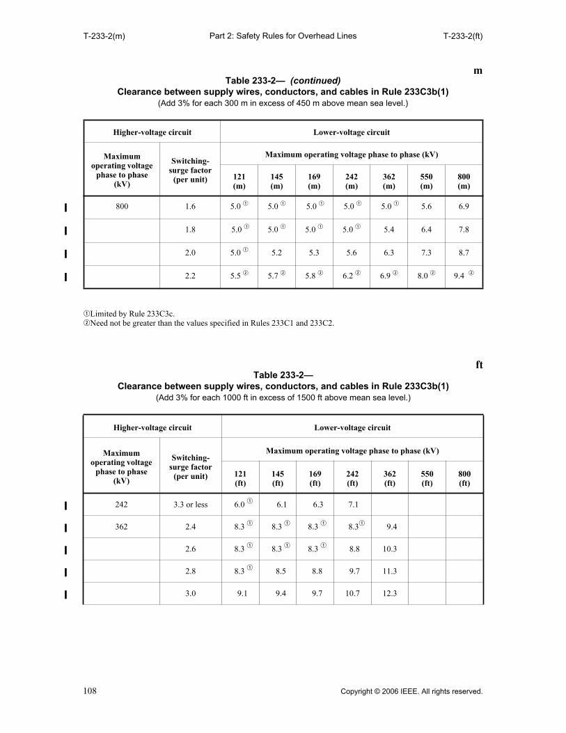
Part 2: Safety Rules for Overhead LinesT-233-2(m) T-233-2(ft)
qLimited by Rule 233C3c.wNeed not be greater than the values specified in Rules 233C1 and 233C2.
800 1.6 5.0 q 5.0 q 5.0 q 5.0 q 5.0 q 5.6 6.9
1.8 5.0 q 5.0 q 5.0 q 5.0 q 5.4 6.4 7.8
2.0 5.0 q 5.2 5.3 5.6 6.3 7.3 8.7
2.2 5.5 w 5.7 w 5.8 w 6.2 w 6.9 w 8.0 w 9.4 w
ftTable 233-2—
Clearance between supply wires, conductors, and cables in Rule 233C3b(1) (Add 3% for each 1000 ft in excess of 1500 ft above mean sea level.)
Higher-voltage circuit Lower-voltage circuit
Maximum operating voltage
phase to phase (kV)
Switching- surge factor
(per unit)
Maximum operating voltage phase to phase (kV)
121(ft)
145(ft)
169(ft)
242(ft)
362(ft)
550(ft)
800(ft)
242 3.3 or less 6.0 q 6.1 6.3 7.1
362 2.4 8.3 q 8.3 q 8.3 q 8.3q 9.4
2.6 8.3 q 8.3 q 8.3 q 8.8 10.3
2.8 8.3 q 8.5 8.8 9.7 11.3
3.0 9.1 9.4 9.7 10.7 12.3
mTable 233-2— (continued)
Clearance between supply wires, conductors, and cables in Rule 233C3b(1)(Add 3% for each 300 m in excess of 450 m above mean sea level.)
Higher-voltage circuit Lower-voltage circuit
Maximum operating voltage
phase to phase (kV)
Switching- surge factor
(per unit)
Maximum operating voltage phase to phase (kV)
121(m)
145(m)
169(m)
242(m)
362(m)
550(m)
800(m)
108 Copyright © 2006 IEEE. All rights reserved.
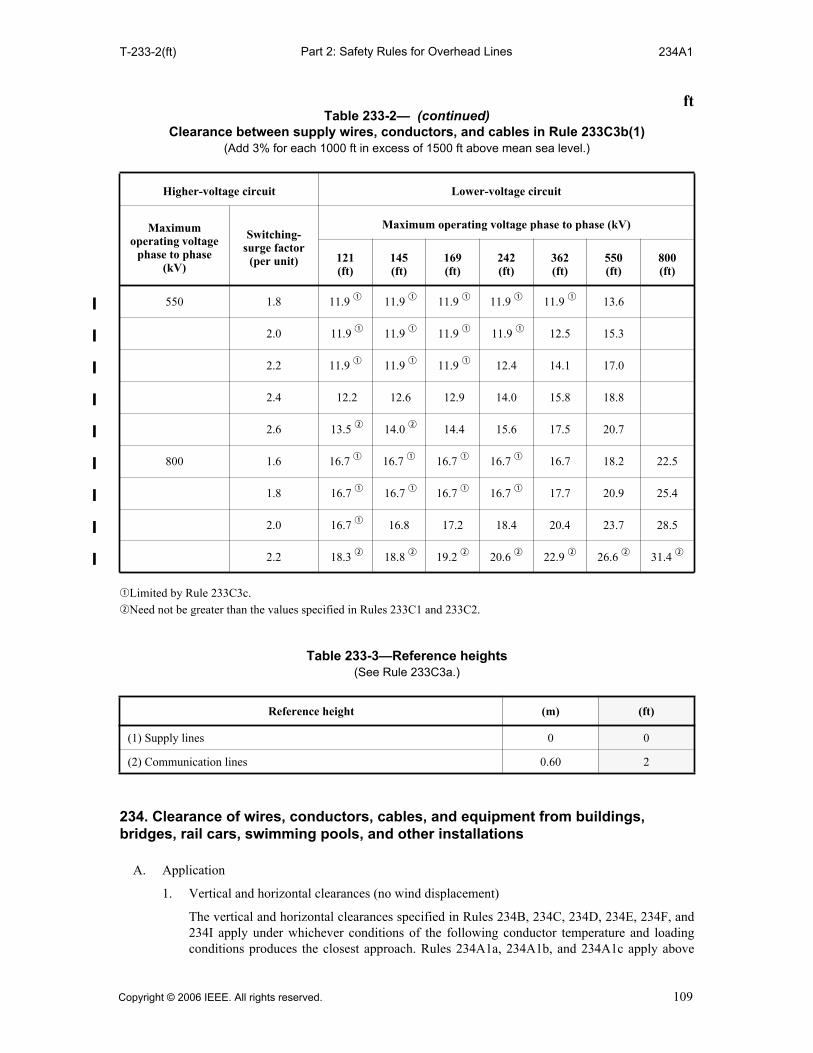
Part 2: Safety Rules for Overhead LinesT-233-2(ft) 234A1
qLimited by Rule 233C3c. wNeed not be greater than the values specified in Rules 233C1 and 233C2.
234. Clearance of wires, conductors, cables, and equipment from buildings, bridges, rail cars, swimming pools, and other installations
A. Application
1. Vertical and horizontal clearances (no wind displacement)
The vertical and horizontal clearances specified in Rules 234B, 234C, 234D, 234E, 234F, and234I apply under whichever conditions of the following conductor temperature and loadingconditions produces the closest approach. Rules 234A1a, 234A1b, and 234A1c apply above
550 1.8 11.9 q 11.9 q 11.9 q 11.9 q 11.9 q 13.6
2.0 11.9 q 11.9 q 11.9 q 11.9 q 12.5 15.3
2.2 11.9 q 11.9 q 11.9 q 12.4 14.1 17.0
2.4 12.2 12.6 12.9 14.0 15.8 18.8
2.6 13.5 w 14.0 w 14.4 15.6 17.5 20.7
800 1.6 16.7 q 16.7 q 16.7 q 16.7 q 16.7 18.2 22.5
1.8 16.7 q 16.7 q 16.7 q 16.7 q 17.7 20.9 25.4
2.0 16.7 q 16.8 17.2 18.4 20.4 23.7 28.5
2.2 18.3 w 18.8 w 19.2 w 20.6 w 22.9 w 26.6 w 31.4 w
Table 233-3—Reference heights(See Rule 233C3a.)
Reference height (m) (ft)
(1) Supply lines 0 0
(2) Communication lines 0.60 2
ftTable 233-2— (continued)
Clearance between supply wires, conductors, and cables in Rule 233C3b(1) (Add 3% for each 1000 ft in excess of 1500 ft above mean sea level.)
Higher-voltage circuit Lower-voltage circuit
Maximum operating voltage
phase to phase (kV)
Switching- surge factor
(per unit)
Maximum operating voltage phase to phase (kV)
121(ft)
145(ft)
169(ft)
242(ft)
362(ft)
550(ft)
800(ft)
Copyright © 2006 IEEE. All rights reserved. 109

Part 2: Safety Rules for Overhead Lines234A1a 234B1b
and alongside subject installations; Rule 234A1d applies below and alongside subjectinstallations.
a. 50 °C (120 °F), no wind displacement, final sag.
b. The maximum conductor temperature for which the line is designed to operate, if greaterthan 50 °C (120 °F), no wind displacement, final sag.
c. 0 °C (32 °F), no wind displacement, final sag, with radial thickness of ice, if any, specifiedin Table 230-1 for the zone concerned.
d. The minimum conductor temperature for which the line is designed, no winddisplacement, initial sag.
EXCEPTION: Vertical or lateral conductors or cables attached directly to the surface of a supportingstructure in accordance with other rules are not subject to the provisions of this rule.
NOTE: The phase and neutral conductors of a supply line are normally considered separately whendetermining the sag of each due to temperature rise.
2. Horizontal clearances (with wind displacement)
Where consideration of horizontal displacement under wind conditions is required, the wires,conductors, or cables shall be considered to be displaced from rest toward the installation by a290 Pa (6 lb/ft2) wind at final sag at 15 °C (60 °F). The displacement of a wire, conductor orcable shall include deflection of suspension insulators. The displacement of a wire, conductor,or cable shall also include deflection of a flexible structure if the highest wire, conductor, orcable attachment is 18 m (60 ft) or more above grade.
EXCEPTION: Where the entire span is so close to a building, terrain feature, or other obstacle as to besheltered from the wind flowing across the line in either direction, the wind pressure may be reduced to a190 Pa (4 lb/ft2) wind. Trees are not considered to shelter a line.
3. Transition between horizontal and vertical clearances
The horizontal clearance governs above the level of the roof or top of an installation to thepoint where the diagonal equals the vertical clearance requirement. Similarly, the horizontalclearance governs above or below projections from buildings, signs, or other installations to thepoint where the diagonal equals the vertical clearance requirement. From this point thetransitional clearance shall equal the vertical clearance as shown in Figures 234-1(a) and234-1(b). This rule should not be interpreted as restricting the installation of a trolley-contactconductor over the approximate center line of the track it serves.
EXCEPTION: When the horizontal clearance is greater than the vertical clearance, the vertical clearancegoverns beyond the roof or top of an installation, or projections from an installation, to the point where thediagonal equals the horizontal clearance requirement, as shown in Figure 234-1(c).
B. Clearances of wires, conductors, and cables from other supporting structures
Wires, conductors, or cables of one line passing near a lighting support, traffic signal support, or asupporting structure of a second line, without being attached thereto, shall have clearance from anypart of such structure not less than the following:
1. Horizontal clearances
a. A horizontal clearance, without wind, of 1.50 m (5 ft) for voltages up to 50 kV.
EXCEPTION: For effectively grounded guys and messengers, insulated communication conductorsand cables, neutrals meeting Rule 230E1, and cables of 300 V or less to ground meeting therequirements of Rule 230C1, 230C2, or 230C3, the horizontal clearance may be reduced to 900 mm(3 ft).
b. When the following conductors and cables are displaced from rest under the windconditions of Rule 234A2, horizontal clearances from such conductors or cables to othersupporting structures shall be not less than those shown below:
110 Copyright © 2006 IEEE. All rights reserved.
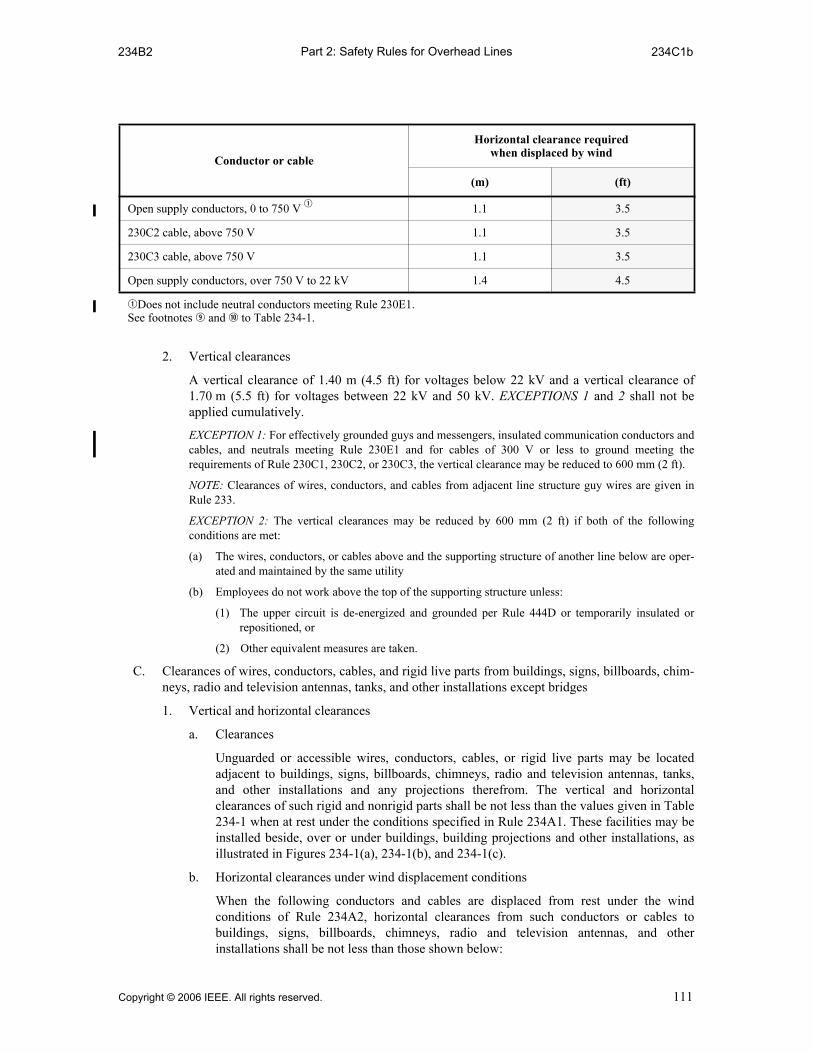
Part 2: Safety Rules for Overhead Lines234B2 234C1b
2. Vertical clearances
A vertical clearance of 1.40 m (4.5 ft) for voltages below 22 kV and a vertical clearance of1.70 m (5.5 ft) for voltages between 22 kV and 50 kV. EXCEPTIONS 1 and 2 shall not beapplied cumulatively.
EXCEPTION 1: For effectively grounded guys and messengers, insulated communication conductors andcables, and neutrals meeting Rule 230E1 and for cables of 300 V or less to ground meeting therequirements of Rule 230C1, 230C2, or 230C3, the vertical clearance may be reduced to 600 mm (2 ft).
NOTE: Clearances of wires, conductors, and cables from adjacent line structure guy wires are given inRule 233.
EXCEPTION 2: The vertical clearances may be reduced by 600 mm (2 ft) if both of the followingconditions are met:
(a) The wires, conductors, or cables above and the supporting structure of another line below are oper-ated and maintained by the same utility
(b) Employees do not work above the top of the supporting structure unless:
(1) The upper circuit is de-energized and grounded per Rule 444D or temporarily insulated orrepositioned, or
(2) Other equivalent measures are taken.
C. Clearances of wires, conductors, cables, and rigid live parts from buildings, signs, billboards, chim-neys, radio and television antennas, tanks, and other installations except bridges
1. Vertical and horizontal clearances
a. Clearances
Unguarded or accessible wires, conductors, cables, or rigid live parts may be locatedadjacent to buildings, signs, billboards, chimneys, radio and television antennas, tanks,and other installations and any projections therefrom. The vertical and horizontalclearances of such rigid and nonrigid parts shall be not less than the values given in Table234-1 when at rest under the conditions specified in Rule 234A1. These facilities may beinstalled beside, over or under buildings, building projections and other installations, asillustrated in Figures 234-1(a), 234-1(b), and 234-1(c).
b. Horizontal clearances under wind displacement conditions
When the following conductors and cables are displaced from rest under the windconditions of Rule 234A2, horizontal clearances from such conductors or cables tobuildings, signs, billboards, chimneys, radio and television antennas, and otherinstallations shall be not less than those shown below:
Conductor or cable
Horizontal clearance requiredwhen displaced by wind
(m) (ft)
Open supply conductors, 0 to 750 V q 1.1 3.5
230C2 cable, above 750 V 1.1 3.5
230C3 cable, above 750 V 1.1 3.5
Open supply conductors, over 750 V to 22 kV 1.4 4.5
qDoes not include neutral conductors meeting Rule 230E1.See footnotes o and a to Table 234-1.
Copyright © 2006 IEEE. All rights reserved. 111

Part 2: Safety Rules for Overhead Lines234C2 234C3d(1)
2. Guarding of supply conductors and rigid live parts
Where the clearances set forth in Table 234-1 cannot be obtained, supply conductors and rigidlive parts shall be guarded. Supply cables meeting Rule 230C1a are considered to be guardedwithin the meaning of this rule.
3. Supply conductors attached to buildings or other installations
Where the permanent attachment of supply conductors of any class to a building or otherinstallation is necessary for an entrance, such conductors shall meet the following requirementsover or along the installation to which the conductors are attached:
a. Energized service drop conductors, including splices and taps, shall be insulated or cov-ered in accordance with the following:
(1) For 0 to 750V, Rule 230C or 230D
(2) For over 750 V, Rule 230C1
This rule does not apply to neutral conductors meeting Rule 230E1.
b. Conductors of more than 300 V to ground shall not be carried along or near the surface ofthe installation unless they are guarded or made inaccessible.
c. Wires or cables attached to and run along side the installation shall have clearances fromthe surface of the installation not less than 75 mm (3 in).
d. Service-drop conductors, including drip loops shall have a clearance of not less than thefollowing:
(1) 3.0 m (10 ft) vertical clearance from the highest point of roofs, balconies, porches, orattached decks over which they pass
EXCEPTION: Where the voltage between conductors meeting Rule 230D does not exceed300 V, or where the voltage of cables meeting Rule 230C2 or 230C3 does not exceed 750 V, orwhere the cable meets Rule 230C1, and the roof, balcony, porch, or attached deck is not readilyaccessible, the clearance over the roof, balcony, porch, or attached deck including the drip loopshall be not less than either of the following:
(a) 900 mm (3 ft)
(b) 457 mm (18 in) for a horizontal distance of 1.8 m (6 ft) from an approved raceway orsupport located not more than 1.2 m (4 ft) from the edge of the roof and not less than 900mm (3 ft) for the remainder of the horizontal distance that the cable or conductor passesover the roof or balcony
A roof, balcony, porch, or attached deck is considered readily accessible to pedestrians if it canbe casually accessed through a doorway, window, ramp, stairway, or permanently mounted
Conductor or cable
Horizontal clearance required when displaced by wind
(m) (ft)
Open supply conductors, 0 to 750 V q 1.1 3.5
230C2 cable, above 750 V 1.1 3.5
230C3 cable, above 750 V 1.1 3.5
Open supply conductors, over 750 V to 22 kV 1.4 4.5
qDoes not include neutral conductors meeting Rule 230E1.See footnotes o and a to Table 234-1.
112 Copyright © 2006 IEEE. All rights reserved.

Part 2: Safety Rules for Overhead Lines234C3d(2) 234D1b
ladder by a person, on foot, who neither exerts extraordinary physical effort nor employs toolsor devices to gain entry. A permanently mounted ladder is not considered a means of access ifits bottom rung is 2.45 m (8 ft) or more from the ground or other permanently installedaccessible surface.
NOTE: See Figure 234-2.
(2) 900 mm (3 ft) in any direction from windows, doors, porches, fire escapes, or similarlocations.
EXCEPTION 1: This does not apply to service-drop conductors meeting Rule 230C3 above thetop level of a window.
EXCEPTION 2: This does not apply to windows that are not designed to open.
4. Communication conductors attached to buildings or other installations
Communication conductors and cables may be attached directly to buildings or otherinstallations.
5. Ladder space
Where buildings or other installations exceed three stories [or 15 m (50 ft)] in height, overheadlines should be arranged where practical so that a clear space or zone at least 1.8 m (6 ft) widewill be left either adjacent to the building or beginning not over 2.45 m (8 ft) from the buildingto facilitate the raising of ladders where necessary for fire fighting.
EXCEPTION: This requirement does not apply where it is the unvarying rule of the local fire departmentsto exclude the use of ladders in alleys or other restricted places that are generally occupied by supplyconductors and cables.
D. Clearance of wires, conductors, cables, and unguarded rigid live parts from bridges
1. Vertical and horizontal clearances
a. Clearances
Unguarded or accessible wires, conductors, cables, or rigid live parts may be locatedadjacent to or within a bridge structure. The vertical and horizontal clearances of suchrigid and nonrigid parts shall be not less than the values given in Table 234-2 when at restunder the conditions specified in Rule 234A1, as illustrated in Figures 234-1(a) and234-1(b).
EXCEPTION: This rule does not apply to insulated communication cables, effectively groundedguys, span wires, and surge protection wires; neutrals meeting Rule 230E1; and supply cablesmeeting Rule 230C1.
b. Horizontal clearances under wind displacement conditions
When the following conductors and cables are displaced from rest under the windconditions of Rule 234A2, horizontal clearances from such conductors or cables to bridgesshall be not less than those shown below:
Conductor or cable
Horizontal clearance required when displaced by wind
(m) (ft)
Open supply conductors, 0 to 750 V q 1.1 3.5
230C2 cable, above 750 V 1.1 3.5
230C3 cable, above 750 V 1.1 3.5
Open supply conductors, over 750 V to 22 kV 1.4 4.5
qDoes not include neutral conductors meeting Rule230E1.See footnotes i and o to Table 234-2.
Copyright © 2006 IEEE. All rights reserved. 113

Part 2: Safety Rules for Overhead Lines234D2 234F2a
2. Guarding trolley-contact conductors located under bridges
a. Where guarding is required
Guarding is required where the trolley-contact conductor is located so that a trolley poleleaving the conductor can make simultaneous contact between it and the bridge structure.
b. Nature of guarding
Guarding shall consist of a substantial inverted trough of nonconducting material locatedabove the contact conductor, or of other suitable means of limiting the likelihood ofcontact between the trolley support and the bridge structure.
E. Clearance of wires, conductors, cables, or unguarded rigid live parts installed over or near swim-ming areas with no wind displacement
1. Swimming pools
Where wires, conductors, cables, or unguarded rigid live parts are over a swimming pool or thesurrounding area, the clearances in any direction shall be not less than those shown in Table234-3 and illustrated in Figure 234-3.
EXCEPTION 1: This rule does not apply to a pool fully enclosed by a solid or screened permanentstructure.
EXCEPTION 2: This rule does not apply to communication conductors and cables, effectively groundedsurge-protection wires, neutral conductors meeting Rule 230E1, guys and messengers, supply cablesmeeting Rule 230C1, and supply cables of 0 to 750 V meeting Rule 230C2 or 230C3 when these facilitiesare 3 m (10 ft) or more horizontally from the edge of the pool, diving platform, diving tower, water slide,or other fixed, pool-related structures.
2. Beaches and waterways restricted to swimming
Where rescue poles are used by lifeguards at supervised swimming beaches, the vertical andhorizontal clearances shall be not less than those shown in Table 234-3. Where rescue poles arenot used, the clearances shall be as specified in Rule 232.
3. Waterways subject to water skiing
The vertical clearance shall be the same as that specified in Rule 232.
F. Clearances of wires, conductors, cables, and rigid live parts from grain bins
1. Grain bins loaded by permanently installed augers, conveyers, or elevator systems
All portions of grain bins that are expected to be loaded by the use of a permanently installedauger, conveyer, or elevator system shall be considered as a building or other installation underRule 234C for the purpose of determining appropriate clearances of wires, conductors, cables,and rigid live parts. In addition, the following clearances shall also apply without winddisplacement. See Figure 234-4(a).
a. A clearance of not less than 5.5 m (18 ft) in all directions above the grain bin shall bemaintained from each probe port in the grain bin roof for all wires, conductors, and cables.
b. A horizontal clearance of not less than 4.6 m (15 ft) shall be maintained between grainbins and open supply conductors, 0 to 22 kV. This clearance does not apply to a neutralconductor meeting Rule 230E1.
2. Grain bins loaded by portable augers, conveyers, or elevators (with no wind displacement)
a. The clearance of wires, conductors, cables, and rigid live parts from grain bins that areexpected to be loaded by the use of a portable auger, conveyer, or elevator shall be not lessthan the values illustrated in Figure 234-4b.
EXCEPTION: Clearances of the following items on the nonloading side of grain bins shall be notless than those required by Rule 234C for clearances from buildings:
(a) Support arms; effectively grounded equipment cases
(b) Insulated communication conductors and cables, messengers, surge-protection wires, groundedguys, neutral conductors meeting Rule 230E1, and supply cables meeting Rule 230C1
(c) Supply cables of 0 to 750 V meeting Rule 230C2 or 230C3
114 Copyright © 2006 IEEE. All rights reserved.

Part 2: Safety Rules for Overhead Lines234F2b 234H3a
b. Any side of a grain bin is considered to be a nonloading side if it is so designated, or if it isso closely abutting another structure or obstruction, or so close to a public road or otherright-of-way that a portable auger, conveyor, or elevator is not reasonably anticipated tobe used over that side or portion to fill the grain bin.
c. Where an agreement excludes the use of portable augers, conveyors, or elevators from adesignated portion of a grain bin, such portion is considered to be a nonloading side.
G. Additional clearances for voltages exceeding 22 kV for wires, conductors, cables, and unguardedrigid live parts of equipment
Greater clearances than specified in Rules 234B, 234C, 234D, 234E, 234F, and 234J shall beprovided where required as follows:
1. For voltages between 22 and 470 kV, the clearance specified in Rules 234B, 234C, 234D,234E, 234F, and 234J shall be increased at the rate of 10 mm (0.4 in) per kV in excess of22 kV. For voltages exceeding 470 kV, the clearance shall be determined by the method givenin Rule 234H. All clearances for lines over 50 kV shall be based on the maximum operatingvoltage.
EXCEPTION 1: Where a clearance value is given for the 22 kV to 50 kV range, the voltage adder of Rule234G1 applies to the voltage in excess of 50 kV.
EXCEPTION 2: For voltages exceeding 98 kV ac to ground or 139 kV dc to ground, clearances less thanthose required above are permitted for systems with known maximum switching-surge factor. (See Rule234H.)
2. For voltages exceeding 50 kV, the additional clearance specified in Rule 234G1 shall beincreased 3% for each 300 m (1000 ft) in excess of 1000 m (3300 ft) above mean sea level.
3. For voltages exceeding 98 kV ac to ground, either the clearances shall be increased or the elec-tric field, or the effects thereof, shall be reduced by other means, as required, to limit thesteady-state current due to electrostatic effects to 5 mA, rms, if an ungrounded metal fence,building, sign, billboard, chimney, radio or television antenna, tank or other installation, or anyungrounded metal attachments thereto, were short-circuited to ground. For this determination,the conductor shall be at a final unloaded sag at 50 °C (120 °F).
H. Alternate clearances for voltages exceeding 98 kV ac to ground or 139 kV dc to ground
The clearances specified in Rules 234B, 234C, 234D, 234E, 234F, 234G, and 234J may be reducedfor circuits with known switching-surge factors, but shall be not less than the alternate clearance,which is computed by adding the reference distance from Rule 234H2 to the electrical component ofclearance from Rule 234H3.
1. Sag conditions of line conductors
The vertical, horizontal, and diagonal clearances shall be maintained under the conductortemperature and loading conditions given in Rule 234A.
2. Reference distances
The reference distance shall be selected from Table 234-5.
3. Electrical component of clearance
a. The electrical component (D) shall be computed using the following equations. Selectedvalues of D are listed in Table 234-4.
D 1.00 V PU( ) a⋅ ⋅500K
-----------------------------1.667
bc m( )=
D 3.28 V PU( ) a⋅ ⋅500K
-----------------------------1.667
bc ft( )=
Copyright © 2006 IEEE. All rights reserved. 115

Part 2: Safety Rules for Overhead Lines234H3b 234J2b
where
V = maximum ac crest operating voltage to ground or maximum dc operating volt-age to ground in kilovolts
PU = maximum switching-surge factor expressed in per-unit peak voltage to groundand defined as a switching-surge level for circuit breakers corresponding to98% probability that the maximum switching surge generated per breakeroperation does not exceed this surge level, or the maximum anticipatedswitching-surge level generated by other means, whichever is greater
a = 1.15, the allowance for three standard deviations b = 1.03, the allowance for nonstandard atmospheric conditions c = the margin of safety:
1.2 for vertical clearances 1.0 for horizontal clearances
K = 1.15, the configuration factor for conductor-to-plane gap
b. The value of D shall be increased 3% for each 300 m (1000 ft) in excess of 450 m(1500 ft) above mean sea level.
4. Limit
The alternate clearance shall be not less than the clearance of Rule 234B, Table 234-1, 234-2,or 234-3, as applicable, computed for 98 kV ac rms to ground by Rule 234G1.
I. Clearance of wires, conductors, and cables to rail cars
Where overhead wires, conductors, or cables run along railroad tracks, the clearance in any directionshall be not less than that shown in Figure 234-5. The values of V and H are as defined as follows:
V = vertical clearance from the wire, conductor, or cable above the top of the rail as specified inRule 232 minus 6.1 m (20 ft), the assumed height of the rail car
H = horizontal clearance from the wire, conductor, or cable to the nearest rail, which is equal to therequired vertical clearance above the rail minus 4.6 m (15 ft) as computed by the lesser of thefollowing:
1. Rules 232B1 and 232C1
2. Rule 232D
These clearances are computed for railroads handling standard rail cars as common carriers ininterchange service with other railroads. Where wires, conductors, or cables run along mine,logging, and similar railways that handle only cars smaller than standard freight cars, the valueof H may be reduced by one-half the difference between the width of a standard rail car [3.3 m(10 ft, 8 in)] and the width of the narrower car.
J. Clearance of equipment mounted on supporting structures
1. Clearance to unguarded rigid live parts of equipment
The horizontal and vertical clearances of unguarded rigid live parts such as potheads,transformer bushings, surge arresters, and short lengths of supply conductors connectedthereto, which are not subject to variation in sag, shall be not less than those required by Rule234C or 234D, as applicable.
2. Clearance to equipment cases
Equipment shall be mounted so that clearances are not less than that given by Rules 234J2a,234J2b, and 234J2c.
a. Effectively grounded equipment cases may be located on or adjacent to buildings, bridges,or other structures provided that clearances for unguarded rigid live parts of such equip-ment, as specified in Rule 234J1, are maintained.
b. Equipment cases that are not effectively grounded shall be located so that the clearancesof Rule 234C or 234D, as applicable, are maintained.
116 Copyright © 2006 IEEE. All rights reserved.
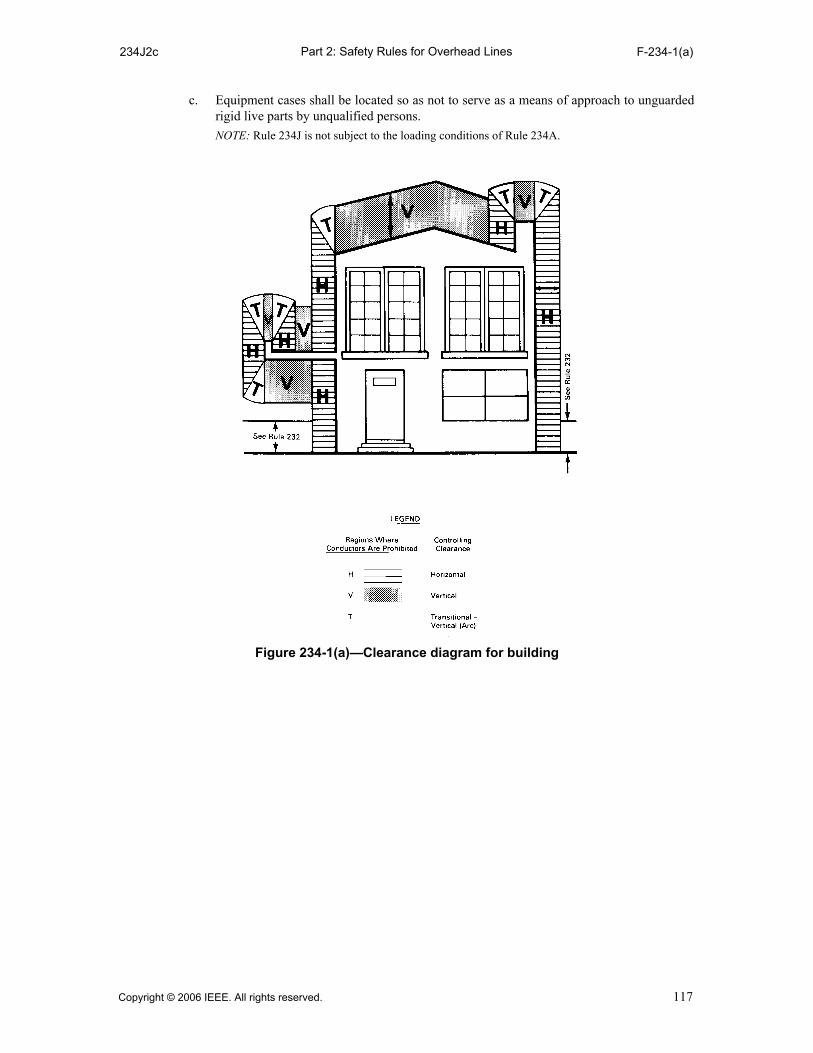
Part 2: Safety Rules for Overhead Lines234J2c F-234-1(a)
c. Equipment cases shall be located so as not to serve as a means of approach to unguardedrigid live parts by unqualified persons.
NOTE: Rule 234J is not subject to the loading conditions of Rule 234A.
Figure 234-1(a)—Clearance diagram for building
Copyright © 2006 IEEE. All rights reserved. 117

Part 2: Safety Rules for Overhead LinesF-234-1(b) F-234-1(c)
Figure 234-1(b)—Clearance diagram for other structures
HBUILDING
V
T
Figure 234-1(c)—Transitional clearance when H is greater than V
118 Copyright © 2006 IEEE. All rights reserved.

Part 2: Safety Rules for Overhead LinesF-234-2 F-234-3
Figure 234-2—Clearances of service drop terminating on support mast
Figure 234-3—Swimming pool clearances
Copyright © 2006 IEEE. All rights reserved. 119
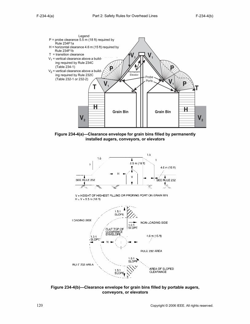
Part 2: Safety Rules for Overhead LinesF-234-4(a) F-234-4(b)
Figure 234-4(a)—Clearance envelope for grain bins filled by permanently installed augers, conveyors, or elevators
LegendP = probe clearance 5.5 m (18 ft) required by
Rule 234F1aH = horizontal clearance 4.6 m (15 ft) required by
Rule 234F1bT = transition clearanceV1 = vertical clearance above a build-
ing required by Rule 234C (Table 234-1)
V2 = vertical clearance above a build-ing required by Rule 232C (Table 232-1 or 232-2)
Figure 234-4(b)—Clearance envelope for grain bins filled by portable augers, conveyors, or elevators
120 Copyright © 2006 IEEE. All rights reserved.
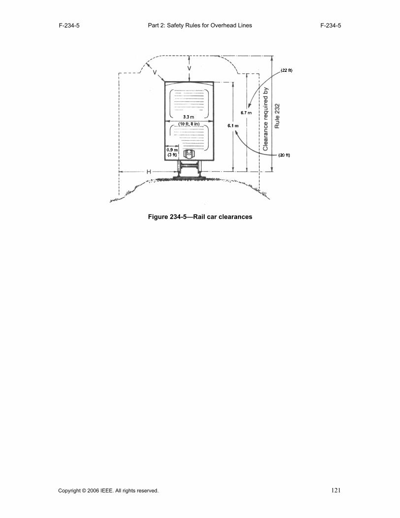
Part 2: Safety Rules for Overhead LinesF-234-5 F-234-5
Figure 234-5—Rail car clearances
Copyright © 2006 IEEE. All rights reserved. 121
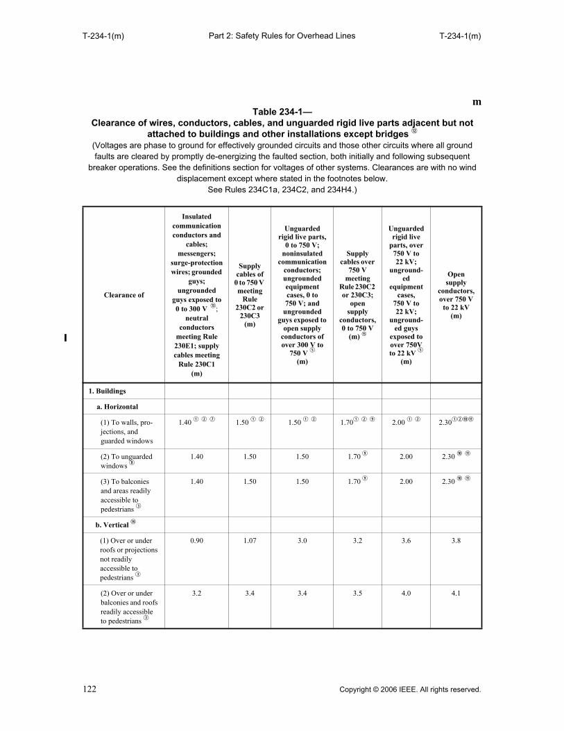
Part 2: Safety Rules for Overhead LinesT-234-1(m) T-234-1(m)
mTable 234-1—
Clearance of wires, conductors, cables, and unguarded rigid live parts adjacent but not attached to buildings and other installations except bridges d
(Voltages are phase to ground for effectively grounded circuits and those other circuits where all ground faults are cleared by promptly de-energizing the faulted section, both initially and following subsequent
breaker operations. See the definitions section for voltages of other systems. Clearances are with no wind displacement except where stated in the footnotes below.
See Rules 234C1a, 234C2, and 234H4.)
Clearance of
Insulated communication conductors and
cables; messengers;
surge-protection wires; grounded
guys; ungrounded
guys exposed to0 to 300 V f;
neutral conductors
meeting Rule 230E1; supply cables meeting
Rule 230C1 (m)
Supply cables of
0 to 750 V meeting
Rule 230C2 or
230C3(m)
Unguarded rigid live parts,
0 to 750 V; noninsulated
communication conductors; ungrounded equipment cases, 0 to 750 V; and
ungrounded guys exposed to
open supply conductors of over 300 V to
750 V t
(m)
Supply cables over
750 V meeting
Rule 230C2 or 230C3;
open supply
conductors, 0 to 750 V
(m) h
Unguarded rigid live
parts, over 750 V to 22 kV;
unground-ed
equipment cases,
750 V to22 kV;
unground-ed guys
exposed to over 750V to 22 kV t
(m)
Open supply
conductors, over 750 V to 22 kV
(m)
1. Buildings
a. Horizontal
(1) To walls, pro-jections, and guarded windows
1.40 q w u 1.50 q w 1.50 q w 1.70q w o 2.00 q w 2.30qwas
(2) To unguarded windows i
1.40 1.50 1.50 1.70 o 2.00 2.30 a s
(3) To balconies and areas readily accessible to pedestrians e
1.40 1.50 1.50 1.70 o 2.00 2.30 a s
b. Vertical g
(1) Over or under roofs or projections not readily accessible to pedestrians e
0.90 1.07 3.0 3.2 3.6 3.8
(2) Over or under balconies and roofs readily accessible to pedestrians e
3.2 3.4 3.4 3.5 4.0 4.1
122 Copyright © 2006 IEEE. All rights reserved.

Part 2: Safety Rules for Overhead LinesT-234-1(m) T-234-1(m)
(3) Over roofs accessible to vehi-cles but not subject to truck traffic y
3.2 3.4 3.4 3.5 4.0 4.1
(4) Over roofs accessible to truck traffic y
4.7 4.9 4.9 5.0 5.5 5.6
2. Signs, chimneys, billboards, radio and television antennas, tanks, and other installations not classified as buildings or bridges
a. Horizontal r
(1) To portions that are readily accessi-ble to pedestrians e
1.40 1.50 1.50 1.70 o 2.00 2.30 a s
(2) To portions that are not readily accessible to pedestrians e
0.90 1.07 1.50 q w 1.70 qwo 2.00 q w 2.30qwas
b. Vertical
mTable 234-1— (continued)
Clearance of wires, conductors, cables, and unguarded rigid live parts adjacent but not attached to buildings and other installations except bridges d
(Voltages are phase to ground for effectively grounded circuits and those other circuits where all ground faults are cleared by promptly de-energizing the faulted section, both initially and following subsequent
breaker operations. See the definitions section for voltages of other systems. Clearances are with no wind displacement except where stated in the footnotes below.
See Rules 234C1a, 234C2, and 234H4.)
Clearance of
Insulated communication conductors and
cables; messengers;
surge-protection wires; grounded
guys; ungrounded
guys exposed to0 to 300 V f;
neutral conductors
meeting Rule 230E1; supply cables meeting
Rule 230C1 (m)
Supply cables of
0 to 750 V meeting
Rule 230C2 or
230C3(m)
Unguarded rigid live parts,
0 to 750 V; noninsulated
communication conductors; ungrounded equipment cases, 0 to 750 V; and
ungrounded guys exposed to
open supply conductors of over 300 V to
750 V t
(m)
Supply cables over
750 V meeting
Rule 230C2 or 230C3;
open supply
conductors, 0 to 750 V
(m) h
Unguarded rigid live
parts, over 750 V to 22 kV;
unground-ed
equipment cases,
750 V to22 kV;
unground-ed guys
exposed to over 750V to 22 kV t
(m)
Open supply
conductors, over 750 V to 22 kV
(m)
Copyright © 2006 IEEE. All rights reserved. 123

Part 2: Safety Rules for Overhead LinesT-234-1(m) T-234-1(m)
qWhere building, sign, chimney, antenna, tank, or other installation does not require maintenance such as painting,washing, changing of sign letters, or other operations that would require persons to work or pass between wires,conductors, cables, or unguarded rigid live parts and structure, the clearance may be reduced by 0.60 m.
wWhere available space will not permit this value, the clearance may be reduced by 0.60 m wires, provided the wires,conductors, or cables, including splices and taps, and unguarded rigid live parts have a covering that providessufficient dielectric strength to limit the likelihood of a short circuit in case of momentary contact with a structureor building.
eA roof, balcony, or area is considered readily accessible to pedestrians if it can be casually accessed through adoorway, ramp, window, stairway, or permanently mounted ladder by a person on foot who neither exertsextraordinary physical effort nor employs tools or devices to gain entry. A permanently mounted ladder is notconsidered a means of access if its bottom rung is 2.45 m or more from the ground or other permanently installedaccessible surface.
rThe required clearances shall be to the closest approach of motorized signs or moving portions of installationscovered by Rule 234C.
tUngrounded guys and ungrounded portions of guys between guy insulators shall have clearances based on thehighest voltage to which they may be exposed to a slack conductor or guy.
yFor the purpose of this rule, trucks are defined as any vehicle exceeding 2.45 m in height.uThis clearance may be reduced to 75 mm for the grounded portions of guys.iWindows not designed to open may have the clearances permitted for walls and projections. oThe clearance at rest shall be not less than the value shown in this table. Also, when the conductor or cable is
displaced by wind, the clearance shall be not less than 1.07 m; see Rule 234C1b.aThe clearance at rest shall be not less than the value shown in this table. Also, when the conductor or cable is
displaced by wind, the clearance shall be not less than 1.40 m; see Rule 234C1b.
(1) Over or under catwalks and other surfaces upon which personnel walk
3.2 3.4 3.4 3.5 4.0 4.1
(2) Over or under other portions of such installations r
0.90 1.07 1.70 1.80 q 2.30 2.45
mTable 234-1— (continued)
Clearance of wires, conductors, cables, and unguarded rigid live parts adjacent but not attached to buildings and other installations except bridges d
(Voltages are phase to ground for effectively grounded circuits and those other circuits where all ground faults are cleared by promptly de-energizing the faulted section, both initially and following subsequent
breaker operations. See the definitions section for voltages of other systems. Clearances are with no wind displacement except where stated in the footnotes below.
See Rules 234C1a, 234C2, and 234H4.)
Clearance of
Insulated communication conductors and
cables; messengers;
surge-protection wires; grounded
guys; ungrounded
guys exposed to0 to 300 V f;
neutral conductors
meeting Rule 230E1; supply cables meeting
Rule 230C1 (m)
Supply cables of
0 to 750 V meeting
Rule 230C2 or
230C3(m)
Unguarded rigid live parts,
0 to 750 V; noninsulated
communication conductors; ungrounded equipment cases, 0 to 750 V; and
ungrounded guys exposed to
open supply conductors of over 300 V to
750 V t
(m)
Supply cables over
750 V meeting
Rule 230C2 or 230C3;
open supply
conductors, 0 to 750 V
(m) h
Unguarded rigid live
parts, over 750 V to 22 kV;
unground-ed
equipment cases,
750 V to22 kV;
unground-ed guys
exposed to over 750V to 22 kV t
(m)
Open supply
conductors, over 750 V to 22 kV
(m)
124 Copyright © 2006 IEEE. All rights reserved.
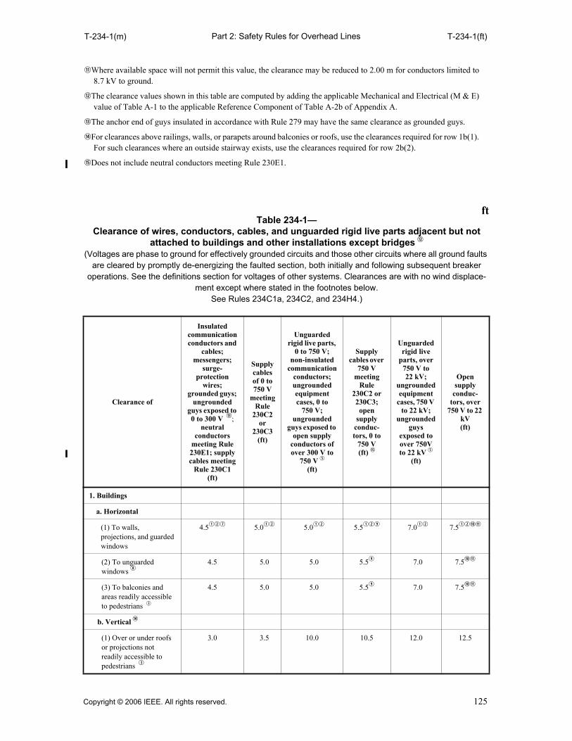
Part 2: Safety Rules for Overhead LinesT-234-1(m) T-234-1(ft)
sWhere available space will not permit this value, the clearance may be reduced to 2.00 m for conductors limited to8.7 kV to ground.
dThe clearance values shown in this table are computed by adding the applicable Mechanical and Electrical (M & E)value of Table A-1 to the applicable Reference Component of Table A-2b of Appendix A.
fThe anchor end of guys insulated in accordance with Rule 279 may have the same clearance as grounded guys.
gFor clearances above railings, walls, or parapets around balconies or roofs, use the clearances required for row 1b(1).For such clearances where an outside stairway exists, use the clearances required for row 2b(2).
hDoes not include neutral conductors meeting Rule 230E1.
ftTable 234-1—
Clearance of wires, conductors, cables, and unguarded rigid live parts adjacent but not attached to buildings and other installations except bridges d
(Voltages are phase to ground for effectively grounded circuits and those other circuits where all ground faults are cleared by promptly de-energizing the faulted section, both initially and following subsequent breaker
operations. See the definitions section for voltages of other systems. Clearances are with no wind displace-ment except where stated in the footnotes below.
See Rules 234C1a, 234C2, and 234H4.)
Clearance of
Insulated communication conductors and
cables; messengers;
surge-protection
wires; grounded guys;
ungrounded guys exposed to 0 to 300 V f;
neutral conductors
meeting Rule 230E1; supply cables meeting
Rule 230C1(ft)
Supply cables of 0 to 750 V
meeting Rule
230C2 or
230C3(ft)
Unguarded rigid live parts,
0 to 750 V; non-insulated
communication conductors; ungrounded equipment cases, 0 to
750 V; ungrounded
guys exposed to open supply
conductors of over 300 V to
750 V t
(ft)
Supply cables over
750 V meeting
Rule 230C2 or 230C3; open
supply conduc-tors, 0 to
750 V (ft) h
Unguarded rigid live
parts, over 750 V to22 kV;
ungrounded equipment
cases, 750 V to 22 kV;
ungrounded guys
exposed to over 750V to 22 kV t
(ft)
Open supply
conduc-tors, over
750 V to 22 kV(ft)
1. Buildings
a. Horizontal
(1) To walls, projections, and guarded windows
4.5qwu 5.0qw 5.0qw 5.5qwo 7.0qw 7.5qwas
(2) To unguarded windows i
4.5 5.0 5.0 5.5o 7.0 7.5as
(3) To balconies and areas readily accessible to pedestrians e
4.5 5.0 5.0 5.5o 7.0 7.5as
b. Vertical g
(1) Over or under roofs or projections not readily accessible to pedestrians e
3.0 3.5 10.0 10.5 12.0 12.5
Copyright © 2006 IEEE. All rights reserved. 125
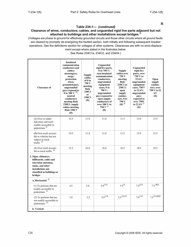
Part 2: Safety Rules for Overhead LinesT-234-1(ft) T-234-1(ft)
(2) Over or under balconies and roofs readily accessible to pedestrians e
10.5 11.0 11.0 11.5 13.0 13.5
(3) Over roofs accessi-ble to vehicles but not subject to truck traffic y
10.5 11.0 11.0 11.5 13.0 13.5
(4) Over roofs accessi-ble to truck traffic y
15.5 16.0 16.0 16.5 18.0 18.5
2. Signs, chimneys, billboards, radio and television antennas, tanks, and other installations not classified as buildings or bridges
a. Horizontal r
(1) To portions that are readily accessible to pedestrians e
4.5 5.0 5.0qw 5.5o 7.0qw 7.5 as
(2) To portions that are not readily accessible to pedestrians e
3.0 3.5 5.0qw 5.5qwo 7.0qw 7.5qwas
b. Vertical
ftTable 234-1— (continued)
Clearance of wires, conductors, cables, and unguarded rigid live parts adjacent but not attached to buildings and other installations except bridges d
(Voltages are phase to ground for effectively grounded circuits and those other circuits where all ground faults are cleared by promptly de-energizing the faulted section, both initially and following subsequent breaker
operations. See the definitions section for voltages of other systems. Clearances are with no wind displace-ment except where stated in the footnotes below.
See Rules 234C1a, 234C2, and 234H4.)
Clearance of
Insulated communication conductors and
cables; messengers;
surge-protection
wires; grounded guys;
ungrounded guys exposed to 0 to 300 V f;
neutral conductors
meeting Rule 230E1; supply cables meeting
Rule 230C1(ft)
Supply cables of 0 to 750 V
meeting Rule
230C2 or
230C3(ft)
Unguarded rigid live parts,
0 to 750 V; non-insulated
communication conductors; ungrounded equipment cases, 0 to
750 V; ungrounded
guys exposed to open supply
conductors of over 300 V to
750 V t
(ft)
Supply cables over
750 V meeting
Rule 230C2 or 230C3; open
supply conduc-tors, 0 to
750 V (ft) h
Unguarded rigid live
parts, over 750 V to22 kV;
ungrounded equipment
cases, 750 V to 22 kV;
ungrounded guys
exposed to over 750V to 22 kV t
(ft)
Open supply
conduc-tors, over
750 V to 22 kV(ft)
126 Copyright © 2006 IEEE. All rights reserved.

Part 2: Safety Rules for Overhead LinesT-234-1(ft) T-234-1(ft)
qWhere building, sign, chimney, antenna, tank, or other installation does not require maintenance such as painting,washing, changing of sign letters, or other operations that would require persons to work or pass between wires,conductors, cables or unguarded rigid live parts and structure, the clearance may be reduced by 2 ft.
wWhere available space will not permit this value, the clearance may be reduced by 2 ft provided the wires,conductors, or cables, including splices and taps, and unguarded rigid live parts have a covering that providessufficient dielectric strength to limit the likelihood of a short circuit in case of momentary contact with a structureor building.
eA roof, balcony, or area is considered readily accessible to pedestrians if it can be casually accessed through adoorway, ramp, window, stairway, or permanently mounted ladder by a person on foot who neither exertsextraordinary physical effort nor employs tools or devices to gain entry. A permanently mounted ladder is notconsidered a means of access if its bottom rung is 8 ft or more from the ground or other permanently installedaccessible surface.
rThe required clearances shall be to the closest approach of motorized signs or moving portions of installationscovered by Rule 234C.
tUngrounded guys and ungrounded portion of guys between guy insulators shall have clearances based on the highestvoltage to which they may be exposed to a slack conductor or guy.
yFor the purpose of this rule, trucks are defined as any vehicle exceeding 8 ft in height.uThis clearance may be reduced to 3 in for the grounded portions of guys. iWindows not designed to open may have the clearances permitted for walls and projections. oThe clearance at rest shall be not less than the value shown in this table. Also, when the conductor or cable is
displaced by wind, the clearance shall be not less than 3.5 ft; see Rule 234C1b.aThe clearance at rest shall be not less than the value shown in this table. Also, when the conductor or cable is
displaced by wind, the clearance shall be not less than 4.5 ft; see Rule 234C1b.sWhere available space will not permit this value, the clearance may be reduced to 7.0 ft for conductors limited to 8.7
kV to ground.
(1) Over or under cat-walks and other surfaces upon which personnel walk
10.5 11.0 11.0 11.5 13.0 13.5
(2) Over or under other portions of such installations r
3.0 3.5 5.5 6.0q 7.5 8.0
ftTable 234-1— (continued)
Clearance of wires, conductors, cables, and unguarded rigid live parts adjacent but not attached to buildings and other installations except bridges d
(Voltages are phase to ground for effectively grounded circuits and those other circuits where all ground faults are cleared by promptly de-energizing the faulted section, both initially and following subsequent breaker
operations. See the definitions section for voltages of other systems. Clearances are with no wind displace-ment except where stated in the footnotes below.
See Rules 234C1a, 234C2, and 234H4.)
Clearance of
Insulated communication conductors and
cables; messengers;
surge-protection
wires; grounded guys;
ungrounded guys exposed to 0 to 300 V f;
neutral conductors
meeting Rule 230E1; supply cables meeting
Rule 230C1(ft)
Supply cables of 0 to 750 V
meeting Rule
230C2 or
230C3(ft)
Unguarded rigid live parts,
0 to 750 V; non-insulated
communication conductors; ungrounded equipment cases, 0 to
750 V; ungrounded
guys exposed to open supply
conductors of over 300 V to
750 V t
(ft)
Supply cables over
750 V meeting
Rule 230C2 or 230C3; open
supply conduc-tors, 0 to
750 V (ft) h
Unguarded rigid live
parts, over 750 V to22 kV;
ungrounded equipment
cases, 750 V to 22 kV;
ungrounded guys
exposed to over 750V to 22 kV t
(ft)
Open supply
conduc-tors, over
750 V to 22 kV(ft)
Copyright © 2006 IEEE. All rights reserved. 127

Part 2: Safety Rules for Overhead LinesT-234-1(ft) T-234-2(m)
dThe clearance values shown in this table are computed by adding the applicable Mechanical and Electrical (M & E)value of Table A-1 to the applicable Reference Component of Table A-2b of Appendix A.
fThe anchor end of guys insulated in accordance with Rule 279 may have the same clearance as grounded guys.gFor clearances above railings, walls, or parapets around balconies or roofs, use the clearances required for row 1b(1).
For such clearances where an outside stairway exists, use the clearances required for row 2b(2).hDoes not include neutral conductors meeting Rule 230E1.
mTable 234-2—
Clearance of wires, conductors, cables, and unguarded rigid live parts from bridges (Voltages are phase to ground for effectively grounded circuits and those other circuits where all ground faults are cleared by promptly de-energizing the faulted section, both initially and following subsequent
breaker operations. See the definitions section for voltages of other systems. Clearances are with no wind displacement except where stated in the footnotes below.
See Rules 234D1a and 234H4.)
Unguarded rigid live parts, 0 to
750 V; noninsulated
communication conductors; supply cables of 0 to 750 V
meeting Rule 230C2 or 230C3 u;
ungrounded equipment cases,
0 to 750 V; ungrounded guys exposed to open
supply conductors over 300 V to
750 V r
(m)
Supply cables over 750 V
meeting Rule 230C2 or
230C3 u; open supply
conductors, 0 to 750 V
(m) a
Open supply
conduc-tors, over 750 V to
22 kV (m)
Unguarded rigid live
parts, over 750 V to 22 kV,
ungrounded equipment
cases, 750 V to 22 kV;
ungrounded guys exposed
to open supply
conductors of over 750 V to
22 kV r
(m)
1. Clearance over bridges q
a. Attached e 0.90 1.07 1.70 1.50
b. Not attached 3.0 3.2 3.8 3.6
2. Clearance beside, under, or within bridge structure y
a. Readily accessible portions of any bridge including wing, walls, and bridge attachments q
(1) Attached e 0.90 1.07 i 1.70 o 1.50
(2) Not attached 1.50 1.70 i 2.30 o 2.00
b. Ordinarily inaccessible portions of bridges (other than brick, concrete, or masonry) and from abutments w
(1) Attached e t 0.90 1.07 i 1.70 o 1.50
(2) Not attached r t 1.20 1.40 i 2.00 o 1.80
128 Copyright © 2006 IEEE. All rights reserved.

Part 2: Safety Rules for Overhead LinesT-234-2(m) T-234-2(ft)
qWhere over traveled ways on or near bridges, the clearances of Rule 232 apply also.wBridge seats of steel bridges carried on masonry, brick, or concrete abutments that require frequent access for
inspection shall be considered as readily accessible portions. eClearance from supply conductors to supporting arms and brackets attached to bridges shall be the same as specified
in Table 235-6 (Rule 235E1) if the supporting arms and brackets are owned, operated, or maintained by the sameutility.
rUngrounded guys and ungrounded portions of guys between guy insulators shall have clearances based on thehighest voltage to which they may be exposed due to a slack conductor or guy.
tWhere conductors passing under bridges are adequately guarded against contact by unauthorized persons and can bede-energized and grounded per Rule 444D for maintenance of the bridge, clearances of the conductors from thebridge, at any point, may have the clearances specified in Table 235-6 for clearance from surfaces of support armsplus one-half the final unloaded sag of the conductor at that point.
yWhere the bridge has moving parts, such as a lift bridge, the required clearances shall be maintained throughout thefull range of movement of the bridge or any attachment thereto.
uWhere permitted by the bridge owner, supply cables may be run in rigid conduit attached directly to the bridge. Referto Part 3 for installation rules.
iThe clearance at rest shall be not less than the value shown in this table. Also, when the conductor or cable isdisplaced by wind, the clearance shall be not less than 1.07 m; see Rule 234D1b.
oThe clearance at rest shall be not less than the value shown in this table. Also, when the conductor or cable isdisplaced by wind, the clearance shall be not less than 1.40 m; see Rule 234D1b.
aDoes not include neutral conductors meeting Rule 230E1.
ftTable 234-2—
Clearance of wires, conductors, cables, and unguarded rigid live parts from bridges(Voltages are phase to ground for effectively grounded circuits and those other circuits where all ground faults
are cleared by promptly de-energizing the faulted section, both initially and following subsequent breaker operations. See the definitions section for voltages of other systems. Clearances are with no wind displace-
ment except where stated in the footnotes below. See Rules 234D1a and 234H4.)
Unguarded rigid live parts, 0 to
750 V; noninsulated communication
conductors; supply cables of 0 to 750 V
meeting Rule 230C2 or 230C3 u,
ungrounded equipment cases,
0 to 750 V; ungrounded guys exposed to open
supply conductors over 300 V to
750 V r
(ft)
Supply cables over 750 V
meeting Rule 230C2 or 230C3 u;
open supply conductors, 0 to 750 V
(ft) a
Open supply conductors, over 750 V to 22 kV
(ft)
Unguarded rigid live parts, over 750 V to
22 kV, ungrounded equipment
cases, 750 V to 22 kV;
ungrounded guys exposed to
open supply conductors of over 750 V to
22 kV r
(ft)
1. Clearance over bridges q
a. Attached e 3.0 3.5 5.5 5.0
b. Not attached 10.0 10.5 12.5 12.0
2. Clearance beside, under, or within bridge structure y
Copyright © 2006 IEEE. All rights reserved. 129
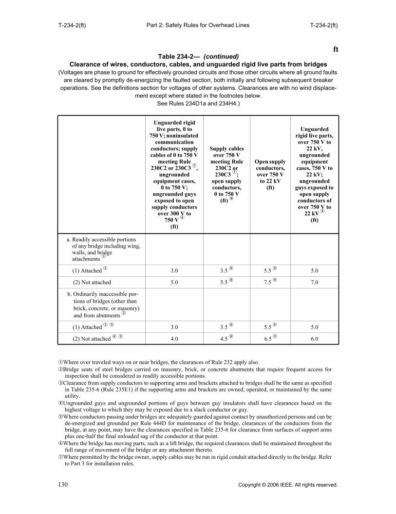
Part 2: Safety Rules for Overhead LinesT-234-2(ft) T-234-2(ft)
qWhere over traveled ways on or near bridges, the clearances of Rule 232 apply also.wBridge seats of steel bridges carried on masonry, brick, or concrete abutments that require frequent access for
inspection shall be considered as readily accessible portions.eClearance from supply conductors to supporting arms and brackets attached to bridges shall be the same as specified
in Table 235-6 (Rule 235E1) if the supporting arms and brackets are owned, operated, or maintained by the sameutility.
rUngrounded guys and ungrounded portions of guys between guy insulators shall have clearances based on thehighest voltage to which they may be exposed due to a slack conductor or guy.
tWhere conductors passing under bridges are adequately guarded against contact by unauthorized persons and can bede-energized and grounded per Rule 444D for maintenance of the bridge, clearances of the conductors from thebridge, at any point, may have the clearances specified in Table 235-6 for clearance from surfaces of support armsplus one-half the final unloaded sag of the conductor at that point.
yWhere the bridge has moving parts, such as a lift bridge, the required clearances shall be maintained throughout thefull range of movement of the bridge or any attachment thereto.
uWhere permitted by the bridge owner, supply cables may be run in rigid conduit attached directly to the bridge. Referto Part 3 for installation rules.
a. Readily accessible portions of any bridge including wing, walls, and bridge attachments q
(1) Attached e 3.0 3.5 i 5.5 o 5.0
(2) Not attached 5.0 5.5 i 7.5 o 7.0
b. Ordinarily inaccessible por-tions of bridges (other than brick, concrete, or masonry) and from abutments w
(1) Attached e t 3.0 3.5 i 5.5 o 5.0
(2) Not attached r t 4.0 4.5 i 6.5 o 6.0
ftTable 234-2— (continued)
Clearance of wires, conductors, cables, and unguarded rigid live parts from bridges(Voltages are phase to ground for effectively grounded circuits and those other circuits where all ground faults
are cleared by promptly de-energizing the faulted section, both initially and following subsequent breaker operations. See the definitions section for voltages of other systems. Clearances are with no wind displace-
ment except where stated in the footnotes below. See Rules 234D1a and 234H4.)
Unguarded rigid live parts, 0 to
750 V; noninsulated communication
conductors; supply cables of 0 to 750 V
meeting Rule 230C2 or 230C3 u,
ungrounded equipment cases,
0 to 750 V; ungrounded guys exposed to open
supply conductors over 300 V to
750 V r
(ft)
Supply cables over 750 V
meeting Rule 230C2 or 230C3 u;
open supply conductors, 0 to 750 V
(ft) a
Open supply conductors, over 750 V to 22 kV
(ft)
Unguarded rigid live parts, over 750 V to
22 kV, ungrounded equipment
cases, 750 V to 22 kV;
ungrounded guys exposed to
open supply conductors of over 750 V to
22 kV r
(ft)
130 Copyright © 2006 IEEE. All rights reserved.

Part 2: Safety Rules for Overhead LinesT-234-2(ft) T-234-3(m)
iThe clearance at rest shall be not less than the value shown in this table. Also, when the conductor or cable isdisplaced by wind, the clearance shall be not less than 3.5 ft; see Rule 234D1b.
oThe clearance at rest shall be not less than the value shown in this table. Also, when the conductor or cable isdisplaced by wind, the clearance shall be not less than 4.5 ft; see Rule 234D1b.
aDoes not include neutral conductors meeting Rule 230E1.
qThe clearance values shown in this table are computed by adding the applicable Mechanical and Electrical (M & E)value of Table A-1 to the applicable Reference Component of Table A-2b of Appendix A.
wUngrounded guys and ungrounded portions of guys between guy insulators shall have clearances based on thehighest voltage to which they may be exposed due to a slack conductor or guy.
eAnchor guys insulated in accordance with Rule 279 may have the same clearance as grounded guys.rDoes not include neutral conductors meeting Rule 230E1.
mTable 234-3—Clearance of wires, conductors, cables, or unguarded rigid live parts
over or near swimming pools q
(Voltages are phase to ground for effectively grounded circuits and those other circuits where all ground faults are cleared by promptly de-energizing the faulted section, both initially and following subsequent
breaker operations. See the definitions section for voltages of other systems. Clearances are with no wind displacement.
See Rules 234E1, 234E2, and 234H4.)
Insulated communication conductors and
cables; messengers;
surge-protection wires; grounded
guys; ungrounded
guys exposed to 0 to 300 V e;
neutral conductors
meeting Rule 230E1; supply cables meeting
Rule 230C1 (m)
Unguarded rigid live parts,
0 to 750 V; noninsulated
communication conductors;
supply cables of 0 to 750 V
meeting Rule 230C2 or 230C3;
ungrounded guys exposed to
open supply conductors of over 300 V to
750 V w
(m)
Supply cables over 750 V
meeting Rule 230C2 or
230C3; open supply
conductors, 0 to 750 V
(m) r
Unguarded rigid live
parts over 750 V to 22 kV;
unground-ed guys
exposed to over 750 V to 22 kV w
(m)
Open supply
conductors, over 750 V to 22 kV
(m)
A. Clearance in any direction from the water level, edge of pool, base of diving platform, or anchored raft
6.7 6.9 7.0 7.5 7.6
B. Clearance in any direction to the div-ing platform, tower, water slide, or other fixed, pool-related structures
4.3 4.4 4.6 5.1 5.2
V. Vertical clearance over adjacent land
Clearance shall be as required by Rule 232.
NOTE: A, B, and V are shown in Figure 234-3.
Copyright © 2006 IEEE. All rights reserved. 131
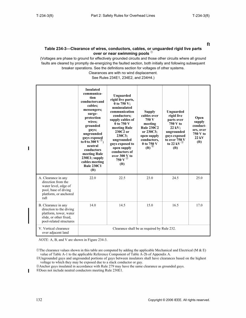
Part 2: Safety Rules for Overhead LinesT-234-3(ft) T-234-3(ft)
qThe clearance values shown in this table are computed by adding the applicable Mechanical and Electrical (M & E)value of Table A-1 to the applicable Reference Component of Table A-2b of Appendix A.
wUngrounded guys and ungrounded portions of guys between insulators shall have clearances based on the highestvoltage to which they may be exposed due to a slack conductor or guy.
eAnchor guys insulated in accordance with Rule 279 may have the same clearance as grounded guys.rDoes not include neutral conductors meeting Rule 230E1.
ftTable 234-3—Clearance of wires, conductors, cables, or unguarded rigid live parts
over or near swimming pools q
(Voltages are phase to ground for effectively grounded circuits and those other circuits where all ground faults are cleared by promptly de-energizing the faulted section, both initially and following subsequent
breaker operations. See the definitions section for voltages of other systems. Clearances are with no wind displacement.
See Rules 234E1, 234E2, and 234H4.)
Insulated communica-
tion conductors and
cables; messengers;
surge-protection
wires; grounded
guys; ungrounded guys exposed
to 0 to 300 V e; neutral
conductors meeting Rule 230E1; supply cables meeting
Rule 230C1 (ft)
Unguarded rigid live parts,
0 to 750 V; noninsulated
communication conductors;
supply cables of 0 to 750 V
meeting Rule 230C2 or 230C3;
ungrounded guys exposed to
open supply conductors of over 300 V to
750 V w
(ft)
Supply cables over
750 V meeting
Rule 230C2 or 230C3;
open supply conductors, 0 to 750 V
(ft) r
Unguarded rigid live
parts over 750 V to 22 kV;
ungrounded guys exposed to over 750 V
to 22 kV w
(ft)
Open supply
conduct-ors, over 750 V to
22 kV
(ft)
A. Clearance in any direction from the water level, edge of pool, base of diving platform, or anchored raft
22.0 22.5 23.0 24.5 25.0
B. Clearance in any direction to the diving platform, tower, water slide, or other fixed, pool-related structures
14.0 14.5 15.0 16.5 17.0
V. Vertical clearance over adjacent land
Clearance shall be as required by Rule 232.
NOTE: A, B, and V are shown in Figure 234-3.
132 Copyright © 2006 IEEE. All rights reserved.
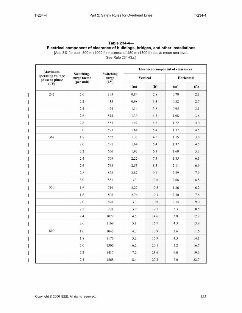
Part 2: Safety Rules for Overhead Lines
T-234-4 T-234-4
Table 234-4— Electrical component of clearance of buildings, bridges, and other installations
[Add 3% for each 300 m (1000 ft) in excess of 450 m (1500 ft) above mean sea level. See Rule 234H3a.]
Maximumoperating voltage
phase to phase (kV)
Switching- surge factor
(per unit)
Switching surge (kV)
Electrical component of clearances
Vertical Horizontal
(m) (ft) (m) (ft)
242 2.0 395 0.84 2.8 0.70 2.3
2.2 435 0.98 3.3 0.82 2.7
2.4 474 1.14 3.8 0.95 3.1
2.6 514 1.30 4.3 1.08 3.6
2.8 553 1.47 4.8 1.22 4.0
3.0 593 1.64 5.4 1.37 4.5
362 1.8 532 1.38 4.5 1.15 3.8
2.0 591 1.64 5.4 1.37 4.5
2.2 650 1.92 6.3 1.60 5.3
2.4 709 2.22 7.3 1.85 6.1
2.6 768 2.53 8.3 2.11 6.9
2.8 828 2.87 9.4 2.39 7.9
3.0 887 3.3 10.6 2.68 8.8
550 1.6 719 2.27 7.5 1.86 6.2
1.8 808 2.76 9.1 2.30 7.6
2.0 898 3.3 10.8 2.74 9.0
2.2 988 3.9 12.7 3.3 10.5
2.4 1079 4.5 14.6 3.8 12.2
2.6 1168 5.1 16.7 4.3 13.9
800 1.6 1045 4.3 13.9 3.6 11.6
1.8 1176 5.2 16.9 4.3 14.1
2.0 1306 6.2 20.1 5.2 16.7
2.2 1437 7.2 23.6 6.0 19.6
2.4 1568 8.4 27.2 7.0 22.7
Copyright © 2006 IEEE. All rights reserved. 133

Part 2: Safety Rules for Overhead LinesT-234-5 235A3b
235. Clearance for wires, conductors, or cables carried on the same supporting structure
A. Application of rule
1. Multiconductor wires or cables
Cables, and duplex, triple, or paired conductors supported on insulators or messengers meetingRule 230C or 230D, whether single or grouped, for the purposes of this rule are consideredsingle conductors even though they may contain individual conductors not of the same phase orpolarity.
2. Conductors supported by messengers or span wires
Clearances between individual wires, conductors, or cables supported by the same messenger,or between any group and its supporting messenger, or between a trolley feeder, supplyconductor, or communication conductor, and their respective supporting span wires, are notsubject to the provisions of this rule.
3. Line conductors of different circuits
a. Unless otherwise stated, the voltage between line conductors of different circuits shall bethe greater of the following:
(1) The phasor difference between the conductors involved
NOTE: A phasor relationship of 180° is considered appropriate where the actual phasorrelationship is unknown.
(2) The phase-to-ground voltage of the higher-voltage circuit
b. When the circuits have the same nominal voltage, either circuit may be considered to bethe higher-voltage circuit.
Table 234-5—Reference distances (See Rule 234H2.)
Reference distanceVertical Horizontal
(m) (ft) (m) (ft)
a. Buildings 2.70 9 0.90 3
b. Signs, chimneys, radio and television antennas, tanks, and other installations not classified as bridges or buildings
2.70 9 0.90 3
c. Superstructure of bridges q w 2.70 9 0.90 3
d. Supporting structures of another line 1.80 6 1.50 5
e. Dimension A of Figure 234-3 5.5 18 — —
f. Dimension B of Figure 234-3 4.3 14 4.3 14
qWhere over traveled ways on or near bridges, the clearances of Rule 232 apply also. wWhere the bridge has moving parts, such as a lift bridge, the required clearances shall be maintained throughout
the full range of movement of the bridge or any attachment thereto.
134 Copyright © 2006 IEEE. All rights reserved.

Part 2: Safety Rules for Overhead Lines235B 235B1b(4)
B. Horizontal clearance between line conductors
1. Fixed supports
Line conductors attached to fixed supports shall have horizontal clearances from each other notless than the larger value required by either Rule 235B1a or 235B1b for the situationconcerned. Voltage is between the two conductors for which the clearance is being determinedexcept for railway feeders, which are to ground.
EXCEPTION 1: The pin spacing at buckarm construction may be reduced as specified in Rule 236F toprovide climbing space.
EXCEPTION 2: Grade N need meet only the requirements of Rule 235B1a.
EXCEPTION 3: These clearances do not apply to cables meeting Rule 230C or covered conductors of thesame circuit meeting Rule 230D.
EXCEPTION 4: For voltages to ground exceeding 98 kV ac or 139 kV dc, clearances less than thoserequired by a and b below are permitted for systems with known maximum switching-surge factors. (SeeRule 235B3.)
a. Horizontal clearance between line conductors of the same or different circuits
Clearances shall be not less than those given in Table 235-1.
b. Clearance according to sags
The clearance at the supports of line conductors of the same or different circuits of GradeB or C in no case shall be less than the values given by the following formulas, at aconductor temperature of 15 °C (60 °F), at final unloaded sag, no wind. For the purpose ofthis rule, the line conductor clearances are between the surfaces of the conductors only,not including armor rods, tie wires, or other fasteners. The requirements of Rule 235B1aapply if they give a greater clearance than this rule.
EXCEPTION: No requirement is specified for clearance between conductors of the same circuitwhen rated above 50 kV.
In the following, S is the apparent sag in millimeters of the conductor having the greatersag, and the clearance is in millimeters. Voltage (kV) is the voltage between theconductors.
(1) For line conductors smaller than AWG No. 2: clearance = 7.6 mm/(kV) +20.4 . (Table 235-2 shows selected values up to 46 kV.)
(2) For line conductors of AWG No. 2 or larger: clearance = 7.6 mm/(kV) + 8 .(Table 235-3 shows selected values up to 46 kV.)
(3) For voltages exceeding 814 kV, the clearance shall be determined by the alternatemethod given by Rule 235B3.
(4) The clearance for voltages exceeding 50 kV specified in Rule 235B1b(1) and (2) shallbe increased 3% for each 300 m in excess of 1000 m above mean sea level. Allclearances for lines over 50 kV shall be based on the maximum operating voltage.
In the following, S is the apparent sag in inches of the conductor having the greater sag,and the clearance is in inches. Voltage (kV) is the voltage between the conductors.
(1) For line conductors smaller than AWG No. 2: clearance = 0.3 in/(kV) + 4.04 .(Table 235-2 shows selected values up to 46 kV.)
(2) For line conductors of AWG No. 2 or larger: clearance = 0.3 in/(kV) + .(Table 235-3 shows selected values up to 46 kV.)
(3) For voltages exceeding 814 kV, the clearance shall be determined by the alternatemethod given by Rule 235B3.
(4) The clearance for voltages exceeding 50 kV specified in Rule 235B1b(1) and (2) shallbe increased 3% for each 1000 ft in excess of 3300 ft above mean sea level. Allclearances for lines over 50 kV shall be based on the maximum operating voltage.
S 610–
2.12S( )
S 24–
8 S 12⁄
Copyright © 2006 IEEE. All rights reserved. 135
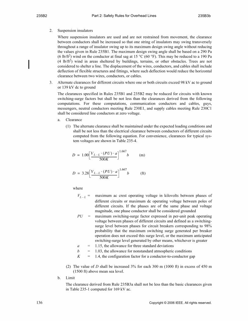
Part 2: Safety Rules for Overhead Lines235B2 235B3b
2. Suspension insulators
Where suspension insulators are used and are not restrained from movement, the clearancebetween conductors shall be increased so that one string of insulators may swing transverselythroughout a range of insulator swing up to its maximum design swing angle without reducingthe values given in Rule 235B1. The maximum design swing angle shall be based on a 290 Pa(6 lb/ft2) wind on the conductor at final sag at 15 °C (60 °F). This may be reduced to a 190 Pa(4 lb/ft2) wind in areas sheltered by buildings, terrains, or other obstacles. Trees are notconsidered to shelter a line. The displacement of the wires, conductors, and cables shall includedeflection of flexible structures and fittings, where such deflection would reduce the horizontalclearance between two wires, conductors, or cables.
3. Alternate clearances for different circuits where one or both circuits exceed 98 kV ac to groundor 139 kV dc to ground
The clearances specified in Rules 235B1 and 235B2 may be reduced for circuits with knownswitching-surge factors but shall be not less than the clearances derived from the followingcomputations. For these computations, communication conductors and cables, guys,messengers, neutral conductors meeting Rule 230E1, and supply cables meeting Rule 230C1shall be considered line conductors at zero voltage.
a. Clearance
(1) The alternate clearance shall be maintained under the expected loading conditions andshall be not less than the electrical clearance between conductors of different circuitscomputed from the following equation. For convenience, clearances for typical sys-tem voltages are shown in Table 235-4.
where
VL – L = maximum ac crest operating voltage in kilovolts between phases ofdifferent circuits or maximum dc operating voltage between poles ofdifferent circuits. If the phases are of the same phase and voltagemagnitude, one phase conductor shall be considered grounded
PU = maximum switching-surge factor expressed in per-unit peak operatingvoltage between phases of different circuits and defined as a switching-surge level between phases for circuit breakers corresponding to 98%probability that the maximum switching surge generated per breakeroperation does not exceed this surge level, or the maximum anticipatedswitching-surge level generated by other means, whichever is greater
a = 1.15, the allowance for three standard deviations b = 1.03, the allowance for nonstandard atmospheric conditions K = 1.4, the configuration factor for a conductor-to-conductor gap
(2) The value of D shall be increased 3% for each 300 m (1000 ft) in excess of 450 m(1500 ft) above mean sea level.
b. Limit
The clearance derived from Rule 235B3a shall not be less than the basic clearances givenin Table 235-1 computed for 169 kV ac.
D 1.00 V L L– PU( ) a⋅ ⋅
500K--------------------------------------
1.667b (m)=
D 3.28 V L L– PU( ) a⋅ ⋅
500K--------------------------------------
1.667b (ft)=
136 Copyright © 2006 IEEE. All rights reserved.

Part 2: Safety Rules for Overhead Lines235C 235C2a(1)
C. Vertical clearance between line conductors
All line wires, conductors, and cables located at different levels on the same supporting structureshall have vertical clearances not less than the following:
1. Basic clearance for conductors of same or different circuits
a. Between supply lines of the same or different circuits
The clearance requirements given in Table 235-5 shall apply to supply line wires,conductors, or cables of 0 to 50 kV attached to supports. No value is specified forclearances between conductors of the same circuit exceeding 50 kV, between cablesmeeting Rule 230C3 and neutral conductors meeting Rule 230E1 of the same utility, orbetween ungrounded open supply conductors 0 to 50 kV of the same phase and circuit ofthe same utility.
b. Between supply lines and communication lines
The clearance requirements given in Table 235-5 shall apply.
c. Between communication lines located in the communication space
The clearance and spacing requirements of Rule 235H shall apply to communication lineslocated in the communication space.
d. Between communication lines located in the supply space
The clearance requirements of Table 235-5 shall apply to communication lines located inthe supply space.
EXCEPTION 1: Line wires, conductors, or cables on vertical racks or separate brackets placed verticallyand meeting the requirements of Rule 235G may have spacings as specified in that rule.
EXCEPTION 2: Where communication service drops cross under supply conductors on a commoncrossing structure, the clearance between the communication conductor and an effectively groundedsupply conductor may be reduced to 100 mm (4 in) provided the clearance between the communicationconductor and supply conductors not effectively grounded meets the requirements of Rule 235C asappropriate.
EXCEPTION 3: Supply service drops of 0 to 750 V running above and parallel to communication servicedrops may have a clearance of not less than 300 mm (12 in) at any point in the span including the point oftheir attachment to the building or structure being served provided that the nongrounded conductors areinsulated and that the clearance as otherwise required by this rule is maintained between the two servicedrops at the pole.
EXCEPTION 4: This rule does not apply to conductors of the same circuit meeting Rule 230D.
2. Additional clearances
Greater clearances than those required (by Rule 235C1) and given in Table 235-5 shall beprovided under the following conditions. The increases are cumulative where more than one isapplicable.
a. Voltage related clearances
(1) For voltages between 50 and 814 kV, the clearance between line wires, conductors, orcables of different circuits shall be increased 10 mm (0.4 in) per kilovolt in excess of50 kV.
EXCEPTION: For voltages to ground exceeding 98 kV ac or 139 kV dc, clearances less thanthose required above are permitted for systems with known switching-surge factors. (See Rule235C3.)
EXAMPLES: Calculations of clearances required by Rule 235C2a for a 69.7 kVmaximum operating voltage phase-to-ground conductor above a 7.2 kV phase-to-ground conductor, assuming conductors are 180° out of phase.
Rule 253C2a: Clearance required at support
Copyright © 2006 IEEE. All rights reserved. 137

Part 2: Safety Rules for Overhead Lines235C2a(1)(a) 235C2b(1)(b)(i)
(a) Same utility [basic clearance = 0.41 m (16 in)]:
SI units: 0.41 + [(50 – 8.7) × 0.01] + [(69.7 + 7.2 – 50) × 0.01] = 1.09 m. Norounding required in this example.
Customary units: 16.0 + [(50 – 8.7) × 0.4] + [(69.7 + 7.2 – 50) × 0.4] = 43.3 in.Round up to 44 in.
(b) Different utilities [basic clearance = 1.00 m (40 in)]:
SI units: 1.00 + [(50 – 8.7) × 0.01] + [(69.7 + 7.2 – 50) × 0.01] = 1.68 m. Norounding required in this example.
Customary units: 40.0 + [(50 – 8.7) × 0.4] + [(69.7 + 7.2 – 50) × 0.4] = 67.3 in.Round up to 68 in.
(2) The increase in clearance for voltages in excess of 50 kV specified in Rule 235C2a(1)shall be increased 3% for each 300 m (1000 ft) in excess of 1000 m (3300 ft) abovemean sea level.
(3) All clearances for lines over 50 kV shall be based on the maximum operating voltage.
(4) No value is specified for clearances between conductors of the same circuit.
b. Sag-related clearances
(1) Line wires, conductors, and cables supported at different levels on the same structuresshall have vertical clearances at the supporting structures so adjusted that the clear-ance at any point in the span shall be not less than any of the following:
(a) For voltages less than 50 kV between conductors, 75% of that required at thesupports by Table 235-5.
EXCEPTION 1: Neutral conductors meeting Rule 230E1, fiber-optic supply cablesmeeting Rule 230F1a or 230F1b, insulated communication cables located in the supplyspace and supported by an effectively grounded messenger, and supply cables meetingRule 230C1 (including their support brackets) in the supply space running above andparallel to communication cables in the communications space where the supply neutralor messenger is bonded to the communication messenger at intervals specified in Rule92C, may have a clearance of 300 mm (12 in) at any point in the span provided that aclearance of 0.75 m (30 in) is maintained between the supply space conductors and cablesand the communication space cables at the supporting poles. Bonding is not required forentirely dielectric cables meeting Rule 230F1b.
EXCEPTION 2: When all parties involved are in agreement, for supply conductors ofdifferent utilities, vertical clearance at any point in the span need not exceed 75% of thevalues required at the supports for the same utility by Table 235-5.
(b) For voltages more than 50 kV between conductors, use the value as calculated bythe following appropriate formula:
If the basic value is 0.41 m (16 in): 0.62 m (24.4 in) plus 10 mm (0.4 in) per kVin excess of 50 kV.
If the basic value is 1.0 m (40 in):1.08 m (42.4 in) plus 10 mm (0.4 in) per kV inexcess of 50 kV.
EXAMPLES: Calculations of clearances required by Rule 235C2b(1)(b) for a69.7 kV maximum operating voltage phase-to-ground conductor above a 7.2 kVphase-to-ground conductor, assuming conductors are 180 degrees out of phase.
Rule 253C2b(1)(b): Clearance required at any point in the span
(i) Same utility [basic clearance = 0.41m (16 in)]:
SI units: 0.41 + [(50 – 8.7) × 0.01] × 0.75 + [(69.7 + 7.2 – 50) × 0.01] = 0.89m. No rounding required in this example.
Customary units: 16.0 + [(50 – 8.7) × 0.4] × 0.75 + [(69.7 + 7.2 – 50) × 0.4] =35.2 in. Round up to 36 in.
138 Copyright © 2006 IEEE. All rights reserved.

Part 2: Safety Rules for Overhead Lines235C2b(1)(b)(ii) 235C4
(ii) Different utilities [basic clearance = 1.00 m (40 in)]:
SI units: 1.00 + [(50 – 8.7) × 0.01] × 0.75 + [(69.7 + 7.2 – 50) × 0.01] =1.33 m. No rounding required in this example.
Customary units: 40.0 + [(50 – 8.7) × 0.4] × 0.75 + [(69.7 + 7.2 – 50) × 0.4] =53.2 in. Round up to 54 in.
(c) For purposes of this determination the vertical clearances required in Rule235C2b(1)(a) and (b) apply to the following conductor temperature and loadingconditions whichever produces the greater vertical clearance at the structurewhen:
i. The upper conductor is at final sag at 120 °F or the maximum operating tem-perature for which the line is designed to operate and the lower conductor isat final sag at the same ambient conditions as the upper conductor withoutelectrical loading, or
ii. The upper conductor is at final sag at 32 °F with the radial thickness of ice, ifany, specified in Table 230-1 for the zone concerned and the lowerconductor is at final sag at the same ambient conditions as the upperconductor without electrical loading, and without ice loading.
EXCEPTION: Rule 235C2b(1)(c) does not apply to conductors of the same utility when theconductors are the same size and type, and are installed at the same sag and tension. However,where experience in an area has shown that different ice conditions do occur between the upperand lower conductors, then Rule 235C2b(1)(c)ii shall apply.
(2) Sags should be readjusted when necessary to accomplish the foregoing, but notreduced sufficiently to conflict with the requirements of Rule 261H1. In cases whereconductors of different sizes are strung to the same sag for the sake of appearance orto maintain unreduced clearance throughout storms, the chosen sag should be such aswill keep the smallest conductor involved in compliance with the sag requirements ofRule 261H1.
(3) For span lengths in excess of 45 m (150 ft), vertical clearance at the structure betweenopen supply conductors and communication cables or conductors shall be adjusted sothat under conditions of conductor temperature of 15 °C (60 °F), no winddisplacement and final unloaded sag, no open supply conductor of over 750 V but lessthan 50 kV shall be lower in the span than a straight line joining the points of supportof the highest communication cable or conductor.
EXCEPTION: Effectively grounded supply conductors associated with systems of 50 kV orless need meet only the provisions of Rule 235C2b(1).
3. Alternate clearances for different circuits where one or both exceed 98 kV ac, or 139 kV dc toground
The clearances specified in Rules 235C1 and 235C2 may be reduced for circuits with knownswitching-surge factors, but shall not be less than the crossing clearances required by Rule233C3.
4. Communication worker safety zone
The clearances specified in Rules 235C and 238 create a communication worker safety zonebetween the facilities located in the supply space and facilities located in the communicationspace, both at the structure and in the span between structures. Except as allowed by Rules238C, 238D, and 239, no supply or communication facility shall be located in thecommunication worker safety zone.
Copyright © 2006 IEEE. All rights reserved. 139

Part 2: Safety Rules for Overhead Lines235D 235E3b(1)(a)
D. Diagonal clearance between line wires, conductors, and cables located at different levels on thesame supporting structure
No wire, conductor, or cable may be closer to any other wire, conductor, or cable than defined by thedashed line in Figure 235-1, where V and H are determined in accordance with other parts of Rule235.
E. Clearances in any direction from line conductors to supports, and to vertical or lateral conductors,span, or guy wires attached to the same support
1. Fixed supports
Clearances shall be not less than those given in Table 235-6.
NOTE 1: For clearances in any direction from supply line conductors to communication antennas in thesupply space attached to the same supporting structure, see Rule 235I.
NOTE 2: For antennas in the communication space, see Rule 236D1.
EXCEPTION: For voltages exceeding 98 kV ac to ground or 139 kV dc to ground, clearances less thanthose required by Table 235-6 are permitted for systems with known switching-surge factor. (See Rule235E3.)
2. Suspension insulators
Where suspension insulators are used and are not restrained from movement, the clearance shall beincreased so that the string of insulators may swing transversely throughout a range of insulatorswing up to its maximum design swing angle without reducing the values given in Rule 235E1. Themaximum design swing angle shall be based on a 290 Pa (6 lb/ft2) wind on the conductor at final sagat 15 °C (60 °F). This may be reduced to a 190 Pa (4 lb/ft2) wind in areas sheltered by buildings,terrain, or other obstacles. Trees are not considered to shelter a line. The displacement of the wires,conductors, and cables shall include deflection of flexible structures and fittings, where suchdeflection would reduce the clearance.
3. Alternate clearances for voltages exceeding 98 kV ac to ground or 139 kV dc to ground
The clearances specified in Rules 235E1 and 235E2 may be reduced for circuits with knownswitching-surge factors but shall not be less than the following:
a. Alternate clearances to anchor guys, surge-protection wires, and vertical or lateralconductors
The alternate clearances shall be not less than the crossing clearances required by Rule233B2 and Rules 233C3a and 233C3b for the conductor voltages concerned. For thepurpose of this rule, anchor guys and surge-protection wires shall be assumed to be atground potential. The limits of Rule 235E3b(2) shall apply to the clearance derived fromRules 233C3a and 233C3b.
b. Alternate clearance to surface of support arms and structures
(1) Alternate clearance
(a) Basic computation
The alternate clearances shall be maintained under the expected loadingconditions and shall be not less than the electrical clearances computed from thefollowing equation. For convenience, clearances for typical system voltages areshown in Table 235-7.
D 1.00 V PU( ) a⋅ ⋅500K
-----------------------------1.667
b (m)=
D 39.37 V PU( ) a⋅ ⋅500K
-----------------------------1.667
b (in)=
140 Copyright © 2006 IEEE. All rights reserved.
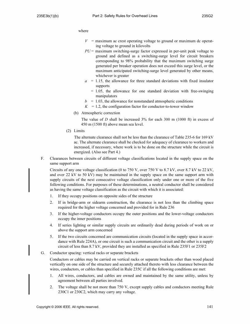
Part 2: Safety Rules for Overhead Lines235E3b(1)(b) 235G2
where
V = maximum ac crest operating voltage to ground or maximum dc operat-ing voltage to ground in kilovolts
PU = maximum switching-surge factor expressed in per-unit peak voltage toground and defined as a switching-surge level for circuit breakerscorresponding to 98% probability that the maximum switching surgegenerated per breaker operation does not exceed this surge level, or themaximum anticipated switching-surge level generated by other means,whichever is greater
a = 1.15, the allowance for three standard deviations with fixed insulatorsupports
= 1.05, the allowance for one standard deviation with free-swingingmanipulators
b = 1.03, the allowance for nonstandard atmospheric conditionsK = 1.2, the configuration factor for conductor-to-tower window
(b) Atmospheric correction
The value of D shall be increased 3% for each 300 m (1000 ft) in excess of450 m (1500 ft) above mean sea level.
(2) Limits
The alternate clearance shall not be less than the clearance of Table 235-6 for 169 kVac. The alternate clearance shall be checked for adequacy of clearance to workers andincreased, if necessary, where work is to be done on the structure while the circuit isenergized. (Also see Part 4.)
F. Clearances between circuits of different voltage classifications located in the supply space on thesame support arm
Circuits of any one voltage classification (0 to 750 V, over 750 V to 8.7 kV, over 8.7 kV to 22 kV,and over 22 kV to 50 kV) may be maintained in the supply space on the same support arm withsupply circuits of the next consecutive voltage classification only under one or more of the fivefollowing conditions. For purposes of these determinations, a neutral conductor shall be consideredas having the same voltage classification as the circuit with which it is associated:
1. If they occupy positions on opposite sides of the structure
2. If in bridge-arm or sidearm construction, the clearance is not less than the climbing spacerequired for the higher voltage concerned and provided for in Rule 236
3. If the higher-voltage conductors occupy the outer positions and the lower-voltage conductorsoccupy the inner positions
4. If series lighting or similar supply circuits are ordinarily dead during periods of work on orabove the support arm concerned
5. If the two circuits concerned are communication circuits (located in the supply space in accor-dance with Rule 224A), or one circuit is such a communication circuit and the other is a supplycircuit of less than 8.7 kV, provided they are installed as specified in Rule 235F1 or 235F2
G. Conductor spacing: vertical racks or separate brackets
Conductors or cables may be carried on vertical racks or separate brackets other than wood placedvertically on one side of the structure and securely attached thereto with less clearance between thewires, conductors, or cables than specified in Rule 235C if all the following conditions are met:
1. All wires, conductors, and cables are owned and maintained by the same utility, unless byagreement between all parties involved.
2. The voltage shall be not more than 750 V, except supply cables and conductors meeting Rule230C1 or 230C2, which may carry any voltage.
Copyright © 2006 IEEE. All rights reserved. 141

Part 2: Safety Rules for Overhead Lines235G3 F-235-1
3. Conductors shall be arranged so that the vertical spacing shall be not less than that specified inTable 235-8 under the conditions specified in Rule 235C2b(1)(c)
4. A supporting neutral conductor of a supply cable meeting Rule 230C3 or an effectivelygrounded messenger of a supply cable meeting Rule 230C1 or 230C2 may attach to the sameinsulator or bracket as a neutral conductor meeting Rule 230E1, so long as the clearances ofTable 235-8 are maintained in mid-span and the insulated energized conductors are positionedaway from the open supply neutral at the attachment.
H. Clearance and spacing between communication conductors, cables, and equipment
1. The spacing between messengers supporting communication cables should be not less than300 mm (12 in) except by agreement between the parties involved.
2. The clearances between the conductors, cables, and equipment of one communication utility tothose of another, anywhere in the span, shall be not less than 100 mm (4 in), except by agree-ment between the parties involved.
I. Clearances in any direction from supply line conductors to communication antennas in the supplyspace attached to the same supporting structure
1. General
Communication antennas located in the supply space shall be installed and maintained only bypersonnel authorized and qualified to work in the supply space in accordance with theapplicable rules of Sections 42 and 44. See also Rule 224A.
2. Communication antenna
The clearance between a communication antenna operated at a radio frequency of 3 kHz to300 GHz and a supply line conductor shall be not less than the value given in Table 235-6, row1b.
NOTE 1: The antenna functions as a rigid, vertical, or lateral open wire communication conductor.
NOTE 2: See Rule 420Q.
3. Equipment case that supports a communication antenna
The clearance between an equipment case that supports a communication antenna and a supplyline conductor shall be not less than the value given in Table 235-6, Row 4a.
4. Vertical or lateral communication conductors and cables attached to a communication antenna
The clearance between a supply line conductor and the vertical or lateral communicationconductor and cable attached to a communication antenna shall be not less than the value givenin Rule 239.
Figure 235-1—Clearance diagram for energized conductor
142 Copyright © 2006 IEEE. All rights reserved.

Part 2: Safety Rules for Overhead LinesT-235-1 T-235-1
Table 235-1—Horizontal clearance between wires, conductors, or cables at supports (All voltages are between conductors involved except for railway feeders, which are to ground.
See also Rules 235A, 235B3b, and 235B1a.)
Class of circuitClearance
Notes(mm) (in)
Open communication conductors 150 6 Does not apply at conductor transposition points.
75 3 Permitted where pin spac-ings less than 150 mm (6 in) have been in regular use. Does not apply at conductor transposition points.
Railway feeders:0 to 750 V, AWG No. 4/0 or larger0 to 750 V, smaller than AWG No. 4/0Over 750 V to 8.7 kV
150300300
61212
Where 250 to 300 mm (10 to 12 in) clearance has already been established by practice, it may be continued, subject to the provisions of Rule 235B1b, for conductors hav-ing apparent sags not over 900 mm (3 ft) and for volt-ages not exceeding 8.7 kV.
Supply conductors of the same circuit: 0 to 8.7 kVOver 8.7 to 50 kV
Above 50 kV
300300 plus 10 per kV in excess of
8.7 kV
No value specified
1212 plus 0.4 per kV
in excess of 8.7 kV
No value specified
Supply conductors of different circuits: 0 to 8.7 kVOver 8.7 to 50 kV
Over 50 kV to 814 kV
300300 plus 10 per kV in excess of
8.7 kV
725 plus 10 per kV over 50 kV
1212 plus 0.4 per kV
in excess of 8.7 kV
28.5 plus 0.4 per kV over 50 kV
For all voltages above 50 kV, the additional clear-ance shall be increased 3% for each 300 m (1000 ft) in excess of 1000 m (3300 ft) above mean sea level. All clearances for voltages above 50 kV shall be based on the maximum operating voltage.
Copyright © 2006 IEEE. All rights reserved. 143

Part 2: Safety Rules for Overhead LinesT-235-2(m) T-235-2(m)
mTable 235-2—Horizontal clearances between line conductors smaller than
AWG No. 2 at supports, based on sags (See also Rule 235B1b.)
Voltage between
conductors(kV)
Sag (mm)
915 1220 1830 2440 3050 4570 6095 But
not less than q
Horizontal clearance (mm)
2.4 375 525 735 895 1030 1305 1530 300
4.16 390 540 745 905 1040 1320 1545 300
12.47 455 600 810 970 1105 1380 1610 340
13.2 460 605 815 975 1100 1385 1615 345
13.8 465 610 820 980 1115 1390 1620 355
14.4 470 615 825 985 1120 1395 1625 360
24.94 550 695 905 1065 1200 1475 1705 465
34.5 620 770 975 1135 1270 1550 1775 560
46 710 855 1065 1225 1360 1635 1865 675
qClearance determined by Table 235-1, Rule 235B1a. NOTE: Clearance = 7.6 (kV) + 20.4 , where S is the sag in millimeters.S 610–
144 Copyright © 2006 IEEE. All rights reserved.

Part 2: Safety Rules for Overhead LinesT-235-2(in) T-235-2(in)
inTable 235-2—Horizontal clearances between line conductors smaller than
AWG No. 2 at supports, based on sags (See also Rule 235B1b.)
Voltage between conductors
(kV)
Sag (in)
36 48 72 96 120 180 240 But
not lessthan q
Horizontal clearance (in)
2.4 15 21 29 36 41 52 61 12
4.16 16 22 30 36 41 52 61 12
12.47 18 24 32 39 44 55 64 14
13.2 18 24 32 39 44 55 64 14
13.8 19 24 33 39 44 55 64 15
14.4 19 25 33 39 44 55 64 15
24.94 22 28 36 42 48 58 67 19
34.5 25 31 39 45 50 61 70 23
46 28 34 42 49 54 65 74 27
qClearance determined by Table 235-1, Rule 235B1a. NOTE: Clearance = 0.3 (kV) + 4.04 , where S is the sag in inches.S 24–
Copyright © 2006 IEEE. All rights reserved. 145

Part 2: Safety Rules for Overhead LinesT-235-3(m) T-235-3(m)
mTable 235-3—Horizontal clearances between line conductors AWG No. 2 or
larger at supports, based on sags (See also Rule 235B1b.)
Voltage between conductors
(kV)
Sag (mm)
915 1220 1830 2440 3050 4570 6095 But
not lessthan q
Horizontal clearance (mm)
2.4 375 430 520 595 665 810 930 300
4.16 385 440 530 610 675 820 945 300
12.47 450 505 595 675 740 885 1005 340
13.2 455 510 600 680 745 890 1010 345
13.8 460 515 605 685 750 895 1015 355
14.4 465 520 610 685 755 900 1020 360
24.94 545 600 690 765 835 980 1100 465
34.5 615 670 765 840 910 1050 1175 560
46 705 760 850 925 995 1140 1260 675
q Clearance determined by Table 235-1, Rule 235B1a. NOTE: Clearance = 7.6 (kV) + , where S is the sag in millimeters.8 2.12S
146 Copyright © 2006 IEEE. All rights reserved.

Part 2: Safety Rules for Overhead LinesT-235-3(in) T-235-3(in)
inTable 235-3—Horizontal clearances between line conductors AWG No. 2 or
larger at supports, based on sags (See also Rule 235B1b.)
Voltage between conductors
(kV)
Sag (in)
36 48 72 96 120 180 240 But
not lessthan q
Horizontal clearance (in)
2.4 15 17 21 24 27 32 37 12
4.16 16 18 21 24 27 33 38 12
12.47 18 20 24 27 30 35 40 14
13.2 18 20 24 27 30 35 40 14
13.8 18 21 24 27 30 36 40 15
14.4 19 21 24 27 30 36 41 15
24.94 22 24 28 31 33 39 44 19
34.5 25 27 30 33 36 42 47 23
46 28 30 34 37 40 45 50 27
qClearance determined by Table 235-1, Rule 235B1a. NOTE: Clearance = 0.3 (kV) + , where S is the sag in inches.8 S 12⁄
Copyright © 2006 IEEE. All rights reserved. 147
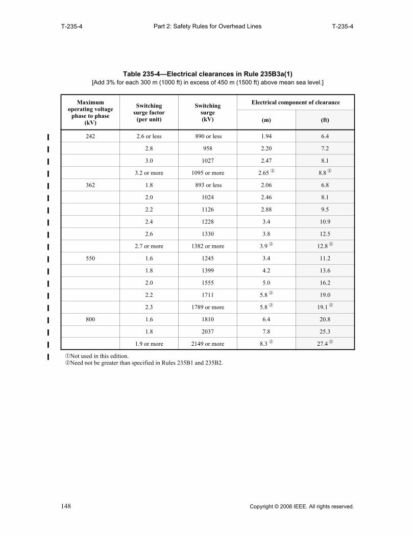
Part 2: Safety Rules for Overhead LinesT-235-4 T-235-4
Table 235-4—Electrical clearances in Rule 235B3a(1) [Add 3% for each 300 m (1000 ft) in excess of 450 m (1500 ft) above mean sea level.]
Maximum operating voltage
phase to phase (kV)
Switchingsurge factor
(per unit)
Switching surge (kV)
Electrical component of clearance
(m) (ft)
242 2.6 or less 890 or less 1.94 6.4
2.8 958 2.20 7.2
3.0 1027 2.47 8.1
3.2 or more 1095 or more 2.65 w 8.8 w
362 1.8 893 or less 2.06 6.8
2.0 1024 2.46 8.1
2.2 1126 2.88 9.5
2.4 1228 3.4 10.9
2.6 1330 3.8 12.5
2.7 or more 1382 or more 3.9 w 12.8 w
550 1.6 1245 3.4 11.2
1.8 1399 4.2 13.6
2.0 1555 5.0 16.2
2.2 1711 5.8 w 19.0
2.3 1789 or more 5.8 w 19.1 w
800 1.6 1810 6.4 20.8
1.8 2037 7.8 25.3
1.9 or more 2149 or more 8.3 w 27.4 w
qNot used in this edition.wNeed not be greater than specified in Rules 235B1 and 235B2.
148 Copyright © 2006 IEEE. All rights reserved.

Part 2: Safety Rules for Overhead Lines
T-235-5(m) T-235-5(m)
mTable 235-5—
Vertical clearance between conductors at supports (When using column and row headings, voltages are phase to ground for effectively grounded circuits and
those other circuits where all ground faults are cleared by promptly de-energizing the faulted section, both ini-tially and following subsequent breaker operations. When calculating clearance values within the table, all
voltages are between the conductors involved. See the definitions section for voltages of other systems. See also Rules 235C1, 235C2, and 235F.)
Conductors and cables usually at lower levels
Conductors and cables usually at upper levels
Supply cables meeting Rule
230C1, 2, or 3; neutral
conductors meeting Rule
230E1; communica-tions cables
meeting Rule 224A2
(m)
Open supply conductors
0 to8.7 kVs
(m)
Over 8.7 to 50 kV
Same utility u
(m)
Different utilitiesu
(m)
1. Communication conductors and cables
a. Located in the communication space
1.00 q t 1.00 1.00 1.00 plus 0.01 per kV y
in excess of 8.7 kV
b. Located in the supply space 0.41o a 0.41 a 1.00 a 1.00 plus 0.01 per kV y
in excess of 8.7 kV
2. Supply conductors and cables
a. Open conductors 0 to 750 V; supply cables meeting Rule 230C1, 2, or 3; neutral conductors meeting Rule 230E1s
0.41 o 0.41 w 0.41 plus 0.01per kV y
in excess of 8.7 kV
1.00 plus 0.01per kV y
in excess of 8.7 kV
b. Open conductors over 750 V to 8.7 kV
0.41 w 0.41 plus 0.01per kV r y
in excess of 8.7 kV
1.00 plus 0.01 per kV A y
in excess of 8.7 kV
c. Open conductors over 8.7 to 22 kV
(1) If worked on energized with live-line tools and adjacent circuits are neither de-energized nor covered with shields or protectors
0.41 plus 0.01 per kV y
in excess of 8.7 kV
1.00 plus 0.01 per kV y
in excess of 8.7 kV
Copyright © 2006 IEEE. All rights reserved. 149

Part 2: Safety Rules for Overhead LinesT-235-5(m) T-235-5(m)
qWhere supply circuits of 600 V or less, with transmitted power of 5000 W or less, are run below communication circuitsin accordance with Rule 220B2, the clearance may be reduced to 0.41 m.
wWhere conductors are operated by different utilities, a vertical clearance of not less than 1.00 m is recommended.
eThese values do not apply to conductors of the same circuit or circuits being carried on adjacent conductor supports.
rMay be reduced to 0.41 m where conductors are not worked on energized except when adjacent circuits (either aboveor below) are de-energized or covered by shields or protectors, or by the use of live-line tools not requiring lineworkers to go between live wires.
tMay be reduced to 30 in for supply neutrals meeting Rule 230E1, fiber-optic supply cables on an effectively groundedmessenger meeting Rule 230F1a, entirely dielectric fiber-optic supply cables meeting Rule 230F1b, insulatedcommunication cables located in the supply space and supported by an effectively grounded messenger, and cablesmeeting Rule 230C1 where the supply neutral or messenger is bonded to the communication messenger. Bonding isnot required for entirely dielectric cables meeting Rule 230F1b.
yThe greater of phasor difference or phase-to-ground voltage; see Rule 235A3.
uSee examples of calculations in Rules 235C2a and 235C2b.
iNot used in this edition.
oNo clearance is specified between neutral conductors meeting Rule 230E1 and insulated communication cables locat-ed in the supply space and supported by an effectively grounded messenger.
aNo clearance is specified between fiber-optic supply cables meeting Rule 230F1b and supply cables and conductors.
sDoes not include neutral conductors meeting Rule 230E1.
(2) If not worked on energized except when adjacent circuits (either above or below) are de-energized or covered by shields or protectors, or by the use of live-line tools not requiring line work-ers to go between live wires
0.41 plus 0.01 per kV e y
in excess of 8.7 kV
0.41 plus 0.01 per kV e y
in excess of 8.7 kV
d. Open conductors exceeding 22 kV, but not exceeding 50 kV
0.41 plus 0.01 per kV e y
in excess of 8.7 kV
1.00 plus 0.01per kV e y
in excess of 8.7 kV
mTable 235-5— (continued)
Vertical clearance between conductors at supports (When using column and row headings, voltages are phase to ground for effectively grounded circuits and
those other circuits where all ground faults are cleared by promptly de-energizing the faulted section, both ini-tially and following subsequent breaker operations. When calculating clearance values within the table, all
voltages are between the conductors involved. See the definitions section for voltages of other systems. See also Rules 235C1, 235C2, and 235F.)
Conductors and cables usually at lower levels
Conductors and cables usually at upper levels
Supply cables meeting Rule
230C1, 2, or 3; neutral
conductors meeting Rule
230E1; communica-tions cables
meeting Rule 224A2
(m)
Open supply conductors
0 to8.7 kVs
(m)
Over 8.7 to 50 kV
Same utility u
(m)
Different utilitiesu
(m)
150 Copyright © 2006 IEEE. All rights reserved.

Part 2: Safety Rules for Overhead LinesT-235-5(in) T-235-5(in)
inTable 235-5—
Vertical clearance between conductors at supports (When using column and row headings, voltages are phase to ground for effectively grounded circuits and those other circuits where all ground faults are cleared by promptly de-energizing the faulted section, both
initially and following subsequent breaker operations. When calculating clearance values within the table, all voltages are between the conductors involved. See the definitions section for voltages of other systems.
See also Rules 235C1, 235C2, and 235F.)
Conductors and cables usually at lower levels
Conductors and cables usually at upper levels
Supply cables meeting Rule
230C1, 2, or 3; neutral
conductors meeting Rule
230E1; communications cables meeting
Rule 224A2 (in)
Open supply conductors
0 to8.7
kV s
(in)
Over 8.7 to 50 kV
Same utility u
(in)
Different utilities u
(in)
1. Communication conductors and cables
a. Located in the communication space
40 q t 40 40 40 plus 0.4per kVy
in excess of 8.7 kV
b. Located in the supply space 16 o a 16 a 40 a 40 plus 0.4 per kV y
in excess of 8.7 kV
2. Supply conductors and cables
a. Open conductors 0 to 750 V; sup-ply cables meeting Rule 230C1, 2, or 3; neutral conductors meeting Rule 230E1 s
16 o 16 w 16 plus 0.4 per kV
y
in excess of 8.7 kV
40 plus 0.4 per kV y
in excess of 8.7 kV
b. Open conductors over 750 V to 8.7 kV
16 w 16 plus 0.4 per kV r y
in excess of 8.7 kV
40 plus 0.4 per kV y
in excess of 8.7 kV
c. Open conductors over 8.7 to 22 kV
(1) If worked on energized with live-line tools and adjacent circuits are neither de-energized nor covered with shields or protectors
16 plus 0.4 per kV y
in excess of 8.7 kV
40 plus 0.4per kV y
in excess of 8.7 kV
Copyright © 2006 IEEE. All rights reserved. 151
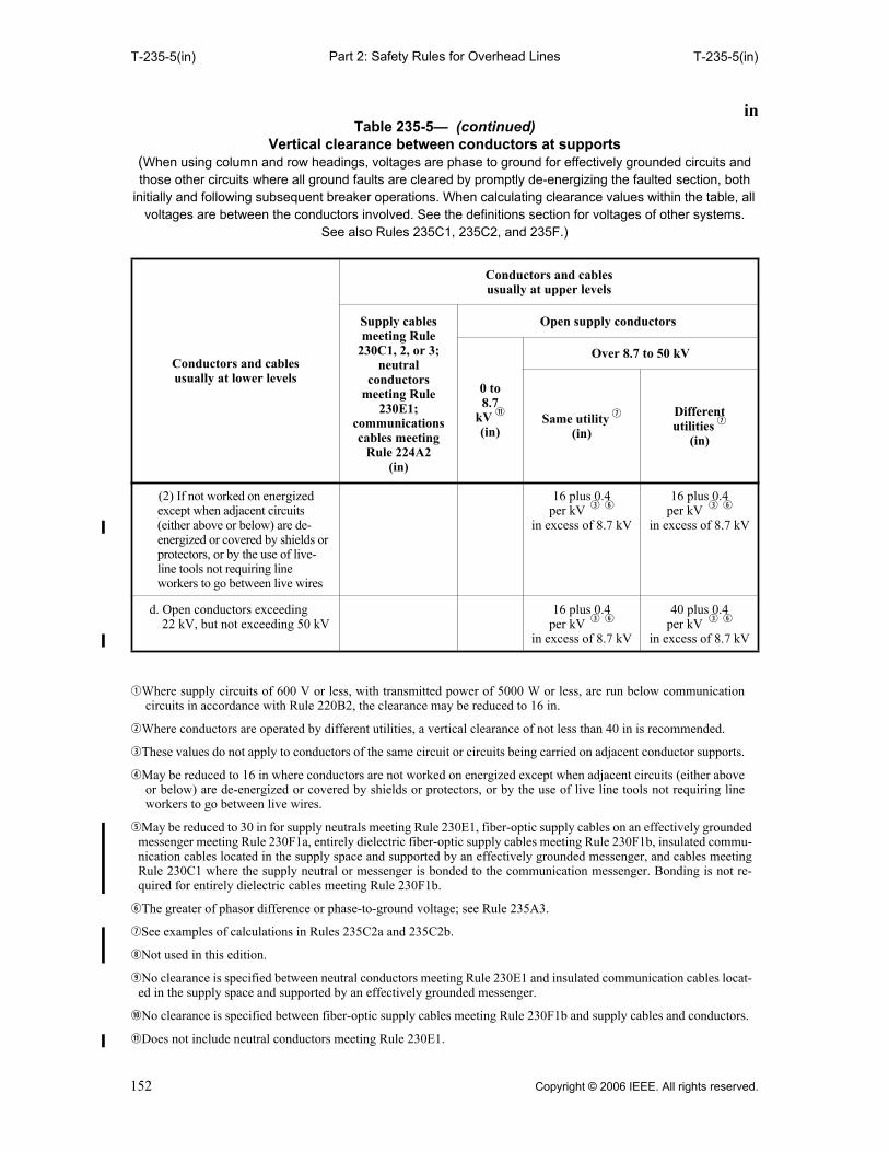
Part 2: Safety Rules for Overhead LinesT-235-5(in) T-235-5(in)
qWhere supply circuits of 600 V or less, with transmitted power of 5000 W or less, are run below communicationcircuits in accordance with Rule 220B2, the clearance may be reduced to 16 in.
wWhere conductors are operated by different utilities, a vertical clearance of not less than 40 in is recommended.
eThese values do not apply to conductors of the same circuit or circuits being carried on adjacent conductor supports.
rMay be reduced to 16 in where conductors are not worked on energized except when adjacent circuits (either aboveor below) are de-energized or covered by shields or protectors, or by the use of live line tools not requiring lineworkers to go between live wires.
tMay be reduced to 30 in for supply neutrals meeting Rule 230E1, fiber-optic supply cables on an effectively groundedmessenger meeting Rule 230F1a, entirely dielectric fiber-optic supply cables meeting Rule 230F1b, insulated commu-nication cables located in the supply space and supported by an effectively grounded messenger, and cables meetingRule 230C1 where the supply neutral or messenger is bonded to the communication messenger. Bonding is not re-quired for entirely dielectric cables meeting Rule 230F1b.
yThe greater of phasor difference or phase-to-ground voltage; see Rule 235A3.
uSee examples of calculations in Rules 235C2a and 235C2b.
iNot used in this edition.
oNo clearance is specified between neutral conductors meeting Rule 230E1 and insulated communication cables locat-ed in the supply space and supported by an effectively grounded messenger.
aNo clearance is specified between fiber-optic supply cables meeting Rule 230F1b and supply cables and conductors.
sDoes not include neutral conductors meeting Rule 230E1.
(2) If not worked on energized except when adjacent circuits (either above or below) are de-energized or covered by shields or protectors, or by the use of live-line tools not requiring line workers to go between live wires
16 plus 0.4 per kV e y
in excess of 8.7 kV
16 plus 0.4 per kV e y
in excess of 8.7 kV
d. Open conductors exceeding 22 kV, but not exceeding 50 kV
16 plus 0.4per kV e y
in excess of 8.7 kV
40 plus 0.4per kV e y
in excess of 8.7 kV
inTable 235-5— (continued)
Vertical clearance between conductors at supports (When using column and row headings, voltages are phase to ground for effectively grounded circuits and those other circuits where all ground faults are cleared by promptly de-energizing the faulted section, both
initially and following subsequent breaker operations. When calculating clearance values within the table, all voltages are between the conductors involved. See the definitions section for voltages of other systems.
See also Rules 235C1, 235C2, and 235F.)
Conductors and cables usually at lower levels
Conductors and cables usually at upper levels
Supply cables meeting Rule
230C1, 2, or 3; neutral
conductors meeting Rule
230E1; communications cables meeting
Rule 224A2 (in)
Open supply conductors
0 to8.7
kV s
(in)
Over 8.7 to 50 kV
Same utility u
(in)
Different utilities u
(in)
152 Copyright © 2006 IEEE. All rights reserved.
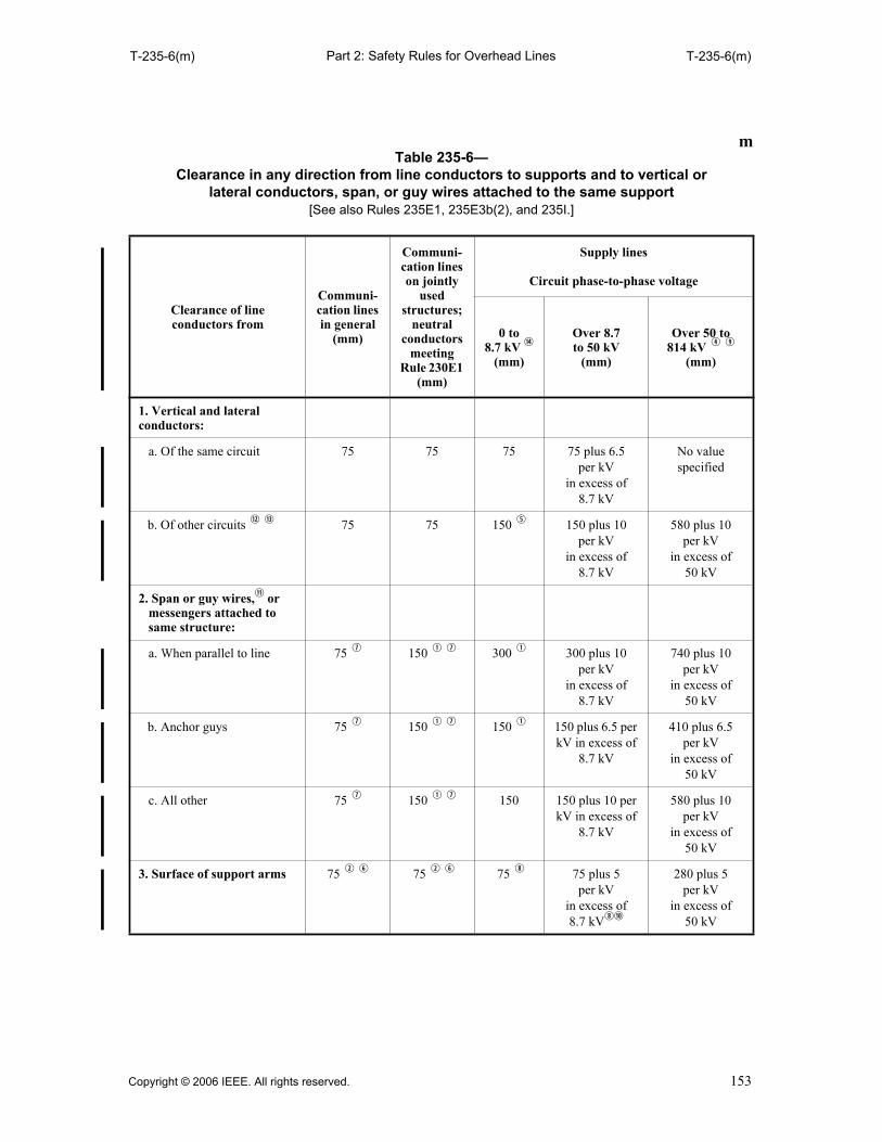
Part 2: Safety Rules for Overhead LinesT-235-6(m) T-235-6(m)
mTable 235-6—
Clearance in any direction from line conductors to supports and to vertical or lateral conductors, span, or guy wires attached to the same support
[See also Rules 235E1, 235E3b(2), and 235I.]
Clearance of lineconductors from
Communi-cation lines in general
(mm)
Communi-cation lines on jointly
usedstructures;
neutral conductors
meeting Rule 230E1
(mm)
Supply lines
Circuit phase-to-phase voltage
0 to8.7 kV g
(mm)
Over 8.7 to 50 kV
(mm)
Over 50 to 814 kV r o
(mm)
1. Vertical and lateral conductors:
a. Of the same circuit 75 75 75 75 plus 6.5 per kV
in excess of 8.7 kV
No value specified
b. Of other circuits d f 75 75 150 t 150 plus 10 per kV
in excess of 8.7 kV
580 plus 10 per kV
in excess of 50 kV
2. Span or guy wires,s or messengers attached to same structure:
a. When parallel to line 75 u 150 q u 300 q 300 plus 10 per kV
in excess of 8.7 kV
740 plus 10 per kV
in excess of 50 kV
b. Anchor guys 75 u 150 q u 150 q 150 plus 6.5 per kV in excess of
8.7 kV
410 plus 6.5per kV
in excess of 50 kV
c. All other 75 u 150 q u 150 150 plus 10 per kV in excess of
8.7 kV
580 plus 10 per kV
in excess of 50 kV
3. Surface of support arms 75 w y 75 w y 75 i 75 plus 5 per kV
in excess of 8.7 kVia
280 plus 5 per kV
in excess of 50 kV
Copyright © 2006 IEEE. All rights reserved. 153
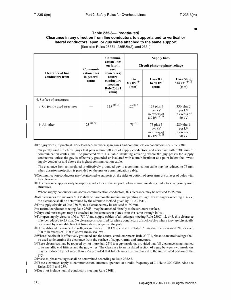
Part 2: Safety Rules for Overhead LinesT-235-6(m) T-235-6(m)
qFor guy wires, if practical. For clearances between span wires and communication conductors, see Rule 238C.
On jointly used structures, guys that pass within 300 mm of supply conductors, and also pass within 300 mm ofcommunication cables, shall be protected with a suitable insulating covering where the guy passes the supplyconductors, unless the guy is effectively grounded or insulated with a strain insulator at a point below the lowestsupply conductor and above the highest communication cable.
The clearance from an insulated or effectively grounded guy to a communication cable may be reduced to 75 mmwhen abrasion protection is provided on the guy or communication cable.
wCommunication conductors may be attached to supports on the sides or bottom of crossarms or surfaces of poles withless clearance.
eThis clearance applies only to supply conductors at the support below communication conductors, on jointly usedstructures.
Where supply conductors are above communication conductors, this clearance may be reduced to 75 mm.
rAll clearances for line over 50 kV shall be based on the maximum operating voltage. For voltages exceeding 814 kV,the clearance shall be determined by the alternate method given by Rule 235E3.
tFor supply circuits of 0 to 750 V, this clearance may be reduced to 75 mm.yA neutral conductor meeting Rule 230E1 may be attached directly to the structure surface.uGuys and messengers may be attached to the same strain plates or to the same through bolts.iFor open supply circuits of 0 to 750 V and supply cables of all voltages meeting Rule 230C1, 2, or 3, this clearance
may be reduced to 25 mm. No clearance is specified for phase conductors of such cables where they are physicallyrestrained by a suitable bracket from abrasion against the pole.
oThe additional clearance for voltages in excess of 50 kV specified in Table 235-6 shall be increased 3% for each300 m in excess of 1000 m above mean sea level.
aWhere the circuit is effectively grounded and the neutral conductor meets Rule 230E1, phase-to-neutral voltage shallbe used to determine the clearance from the surface of support arms and structures.
sThese clearances may be reduced by not more than 25% to a guy insulator, provided that full clearance is maintainedto its metallic end fittings and the guy wires. The clearance to an insulated section of a guy between two insulatorsmay be reduced by not more than 25% provided that full clearance is maintained to the uninsulated portion of theguy.
dPhase-to-phase voltages shall be determined according to Rule 235A3.fThese clearances apply to communication antennas operated at a radio frequency of 3 kHz to 300 GHz. Also see
Rules 235I4 and 239.gDoes not include neutral conductors meeting Rule 230E1.
4. Surface of structures:
a. On jointly used structures — 125 w y 125ei 125 plus 5per kV
in excess of8.7 kV i a
330 plus 5per kV
in excess of 50 kV
b. All other 75 w y — 75 i 75 plus 5 per kV
in excess of8.7 kV i a
280 plus 5 per kV
in excess of 50 kV
mTable 235-6— (continued)
Clearance in any direction from line conductors to supports and to vertical or lateral conductors, span, or guy wires attached to the same support
[See also Rules 235E1, 235E3b(2), and 235I.]
Clearance of lineconductors from
Communi-cation lines in general
(mm)
Communi-cation lines on jointly
usedstructures;
neutral conductors
meeting Rule 230E1
(mm)
Supply lines
Circuit phase-to-phase voltage
0 to8.7 kV g
(mm)
Over 8.7 to 50 kV
(mm)
Over 50 to 814 kV r o
(mm)
154 Copyright © 2006 IEEE. All rights reserved.

Part 2: Safety Rules for Overhead LinesT-235-6(in) T-235-6(in)
inTable 235-6—
Clearance in any direction from line conductors to supports and to vertical or lateral conductors, span, or guy wires attached to the same support
[See also Rules 235E1, 235E3b(2), and 235I.]
Clearance of lineconductors from
Communi-cation lines in general
(in)
Communi-cation lines on jointly
usedstructures;
neutral conductors
meeting Rule 230E1
(in)
Supply lines
Circuit phase-to-phase voltage
0 to 8.7 kV g
(in)
Over 8.7 to 50 kV
(in)
Over 50to 814
kV r o
(in)
1. Vertical and lateral conductors:
a. Of the same circuit 3 3 3 3 plus 0.25 per kV
in excess of 8.7 kV
No value specified
b. Of other circuits d f 3 3 6 t 6 plus 0.4per kV
in excess of 8.7 kV
23 plus 0.4 per kV
in excess of 50 kV
2. Span or guy wires,s or messengers attached to same structure:
a. When parallel to line 3 u 6 q u 12 q 12 plus 0.4 per kV
in excess of 8.7 kV
29 plus 0.4 per kV
in excess of 50 kV
b. Anchor guys 3 u 6 q u 6 u 6 plus 0.25 per kV
in excess of 8.7 kV
16 plus 0.25per kV
in excess of 50 kV
c. All other 3 u 6 q u 6 6 plus 0.4per kV
in excess of 8.7 kV
23 plus 0.4 per kV
in excess of 50 kV
3. Surface of support arms 3 w y 3 w y 3 i 3 plus 0.2per kV
in excess of 8.7 kV ia
11 plus 0.2 per kV
in excess of 50 kV
Copyright © 2006 IEEE. All rights reserved. 155

Part 2: Safety Rules for Overhead LinesT-235-6(in) T-235-6(in)
qFor guy wires, if practical. For clearances between span wires and communication conductors, see Rule 238C.
On jointly used structures, guys that pass within 12 in of supply conductors, and also pass within 12 in ofcommunication cables, shall be protected with a suitable insulating covering where the guy passes the supplyconductors, unless the guy is effectively grounded or insulated with a strain insulator at a point below the lowestsupply conductor and above the highest communication cable.
The clearance from an insulated or effectively grounded guy to a communication cable may be reduced to 3 in whenabrasion protection is provided on the guy or communication cable.
wCommunication conductors may be attached to supports on the sides or bottom of crossarms or surfaces of poles withless clearance.
eThis clearance applies only to supply conductors at the support below communication conductors, on jointly usedstructures.
Where supply conductors are above communication conductors, this clearance may be reduced to 3 in.
rAll clearances for line over 50 kV shall be based on the maximum operating voltage. For voltages exceeding 814 kV,the clearance shall be determined by the alternate method given by Rule 235E3.
tFor supply circuits of 0 to 750 V, this clearance may be reduced to 3 in.yA neutral conductor meeting Rule 230E1 may be attached directly to the structure surface.uGuys and messengers may be attached to the same strain plates or to the same through bolts.iFor open supply circuits of 0 to 750 V and supply cables of all voltages meeting Rule 230C1, 2 or 3, this clearance
may be reduced to 1 in. No clearance is specified for phase conductors of such cables where they are physicallyrestrained by a suitable bracket from abrasion against the pole.
oThe additional clearance for voltages in excess of 50 kV specified in Table 235-6 shall be increased 3% for each1000 ft in excess of 3300 ft above mean sea level.
aWhere the circuit is effectively grounded and the neutral conductor meets Rule 230E1, phase-to-neutral voltage shallbe used to determine the clearance from the surface of support arms and structures.
sThese clearances may be reduced by not more than 25% to a guy insulator, provided that full clearance is maintainedto its metallic end fittings and the guy wires. The clearance to an insulated section of a guy between two insulatorsmay be reduced by not more than 25% provided that full clearance is maintained to the uninsulated portion of theguy.
dPhase-to-phase voltages shall be determined according to Rule 235A3.fThese clearances apply to communication antennas operated at a radio frequency of 3 kHz to 300 GHz. Also see
Rules 235I4 and 239.gDoes not include neutral conductors meeting Rule 230E1.
4. Surface of structures:
a. On jointly used structures — 5 w y 5 e i 5 plus 0.2 per kV
in excess of 8.7 kV i a
13 plus 0.2 per kV
in excess of 50 kV
b. All other 3 w y — 3 i 3 plus 0.2 per kV
in excess of 8.7 kV i a
11 plus 0.2per kV
in excess of 50 kV
inTable 235-6— (continued)
Clearance in any direction from line conductors to supports and to vertical or lateral conductors, span, or guy wires attached to the same support
[See also Rules 235E1, 235E3b(2), and 235I.]
Clearance of lineconductors from
Communi-cation lines in general
(in)
Communi-cation lines on jointly
usedstructures;
neutral conductors
meeting Rule 230E1
(in)
Supply lines
Circuit phase-to-phase voltage
0 to 8.7 kV g
(in)
Over 8.7 to 50 kV
(in)
Over 50to 814
kV r o
(in)
156 Copyright © 2006 IEEE. All rights reserved.

Part 2: Safety Rules for Overhead LinesT-235-7 T-235-7
Table 235-7—Clearance in any direction from line conductors to supports [See also Rules 235E3b and 235E3b(1)(a).]
Maximum operating
voltage phase to phase (kV)
Switching-surge factor
(per unit)
Switching surge (kV)
Computed clearance to supports
Fixed Free swinging at maximum angle
(m) (in) (m) (in)
242 2.4 474 0.88 35 q 0.88 q 35 q
2.6 514 1.01 40 0.88 q 35 q
2.8 553 1.14 45 0.98 39
3.0 593 1.24 w 49 w 1.10 44
3.2 632 1.24w 49 w 1.22 49
362 1.6 473 0.88 q 35 q 0.88 q 35 q
1.8 532 1.07 42 0.92 36
2.0 591 1.27 50 1.09 43
2.2 650 1.49 59 1.28 51
2.4 709 1.72 68 1.48 59
2.5 739 1.84 73 1.59 63
550 1.6 719 1.76 69 1.51 60
1.8 808 2.14 84 1.84 73
2.0 898 2.55 100 2.19 87
2.2 988 2.78 w 111 w 2.57 102
800 1.6 1045 3.3 129 2.82 111
1.8 1176 4.0 157 3.5 136
1.9 1241 4.1w 161 w 3.8 148
2.0 1306 4.1w 161 w 4.1 w 161
qLimited by Rule 235E3(b)(2).wNeed not be greater than specified in Rules 235E1 and 235E2.
Copyright © 2006 IEEE. All rights reserved. 157

Part 2: Safety Rules for Overhead LinesT-235-8 236D2
236. Climbing space
The following requirements apply only to portions of structures that workers ascend.
A. Location and dimensions
1. A climbing space having the horizontal dimensions specified in Rule 236E shall be providedpast any conductors, support arms, or other parts.
2. The climbing space need be provided on one side or corner of the support only.
3. The climbing space shall extend vertically past any conductor or other part between levelsabove and below the conductor as specified in Rules 236E, F, G, and I, but may otherwise beshifted from any side or corner of the support to any other side or corner.
B. Portions of supporting structures in climbing space
Portions of the supporting structure, when included in one side or corner of the climbing space, arenot considered to obstruct the climbing space.
C. Support arm location relative to climbing space
RECOMMENDATION: Support arms should be located on the same side of the pole.
EXCEPTION: This recommendation does not apply where double crossarms are used on any pole or wherecrossarms on any pole are not all parallel.
D. Location of equipment relative to climbing space
1. All supply and communication equipment such as transformers, regulators, capacitors, cableterminals (potheads), amplifiers, loading coils, antennas, surge arresters, switches, etc., whenlocated below conductors or other attachments, shall be mounted outside of the climbing space.
2. All exposed ungrounded conductive parts of luminaires and their supports that are not insulatedfrom current-carrying parts shall be maintained at not less than 500 mm (20 in) from the sur-face of their supporting structure.
EXCEPTION 1: This may be reduced to 125 mm (5 in) if located on the side of the structure opposite thedesignated climbing space.
EXCEPTION 2: This does not apply where the equipment is located at the top or other vertical portion ofthe structure that is not subject to climbing.
Table 235-8—Vertical spacing between conductors supported on vertical racks or separate brackets
Span length Vertical spacing between conductors
(m) (ft) (mm) (in)
0 to 45 0 to 150 100 4
Over 45 to 60 Over 150 to 200 150 6
Over 60 to 75 Over 200 to 250 200 8
Over 75 to 90 Over 250 to 300 300 12
EXCEPTION: The vertical spacing between open wire conductors may be reduced where the conductors are held apartby intermediate spacers, but may not be less than 100 mm (4 in).
158 Copyright © 2006 IEEE. All rights reserved.

Part 2: Safety Rules for Overhead Lines236E 236G
E. Climbing space between conductors
Climbing space between conductors shall be not less than the horizontal dimensions specified inTable 236-1. These dimensions are intended to provide a clear climbing space of 600 mm (24 in)while the conductors bounding the climbing space are covered with temporarily installed protectivecovering rated for the voltage involved. The climbing space shall be provided both along and acrossthe line and shall be projected vertically not less than 1.0 m (40 in) above and below the limitingconductors. Where communication conductors are above supply conductors of more than 8.7 kV toground or 15 kV line to line, the climbing space shall be projected vertically at least 1.50 m (60 in)above the highest supply conductors.
EXCEPTION 1: This rule does not apply if it is the unvarying practice of the employers concerned to prohibitemployees from ascending beyond the conductors or equipment of a given line or structure unless theconductors or equipment are de-energized and grounded per Rule 444D.
EXCEPTION 2: For supply conductors carried on a structure in a position below communications facilities in themanner permitted in Rule 220B2, the climbing space need not extend more than 600 mm (2 ft) above such supplyspace.
EXCEPTION 3: If the conductors are owned, operated, or maintained by the same utility, the climbing spacemay be provided by temporarily moving the line conductors using live-line tools.
F. Climbing space on buckarm construction
Method of providing climbing space on buckarm construction
The full width of climbing space shall be maintained on buckarm construction and shall extendvertically in the same position at least 1.0 m (40 in) [or 1.50 m (60 in) where required by Rule 236E]above and below any limiting conductor.
A six-pin crossarm having pin spacing of 370 mm (14.5 in) may be used to provide a 750 mm(30 in) climbing space on one corner of a junction pole by omitting the pole pins on all arms, andinserting pins midway between the remaining pins so as to give a spacing of 185 mm (7.25 in),provided that all of the following conditions are met:
1. Circuits are less than 8.7 kV to ground or 15 kV line to line
2. Span lengths do not exceed 45 m (150 ft)
3. Sags do not exceed 380 mm (15 in) for wires of AWG No. 2 and larger sizes, or 750 mm(30 in) for wires smaller than AWG No. 2
4. Each conductor on the end of every arm is tied to the same side of its insulator
5. The spacing on the next pole is not less than 370 mm (14.5 in)
G. Climbing space past longitudinal runs not on support arms
The full width of climbing space shall be provided past longitudinal runs and shall extend verticallyin the same position from 1.0 m (40 in) below the run to a point 1.0 m (40 in) above [or 1.50 m(60 in) where required by Rule 236E]. The width of climbing space shall be measured from thelongitudinal run concerned. Longitudinal runs on racks, or cables on messengers, are not consideredas obstructing the climbing space if the location, size, and quantity of the cables permit qualifiedworkers to climb past them. This does not apply where communication conductors are above thelongitudinal runs concerned.
EXCEPTION 1: If a supply longitudinal run is placed on the side or corner of the supporting structure whereclimbing space is provided, the width of climbing space shall be measured horizontally from the center of thestructure to the nearest supply conductors on support arms, under both of the following conditions:
(a)Where the longitudinal run consists of neutral conductors meeting Rule 230E1, open supply conductorscarrying not more than 750 V, or supply cables and conductors meeting Rule 230C, all voltages; and issupported close to the structure as by brackets, racks, or pins close to the structure
(b)Where the nearest supply conductors on support arms are parallel to and on the same side of the structure asthe longitudinal run and within 1.20 m (4 ft) above or below the run
EXCEPTION 2: For supply conductors carried on a structure in a position below communications facilities inthe manner permitted in Rule 220B2, the climbing space need not extend more than 600 mm (2 ft) above suchsupply space.
Copyright © 2006 IEEE. All rights reserved. 159
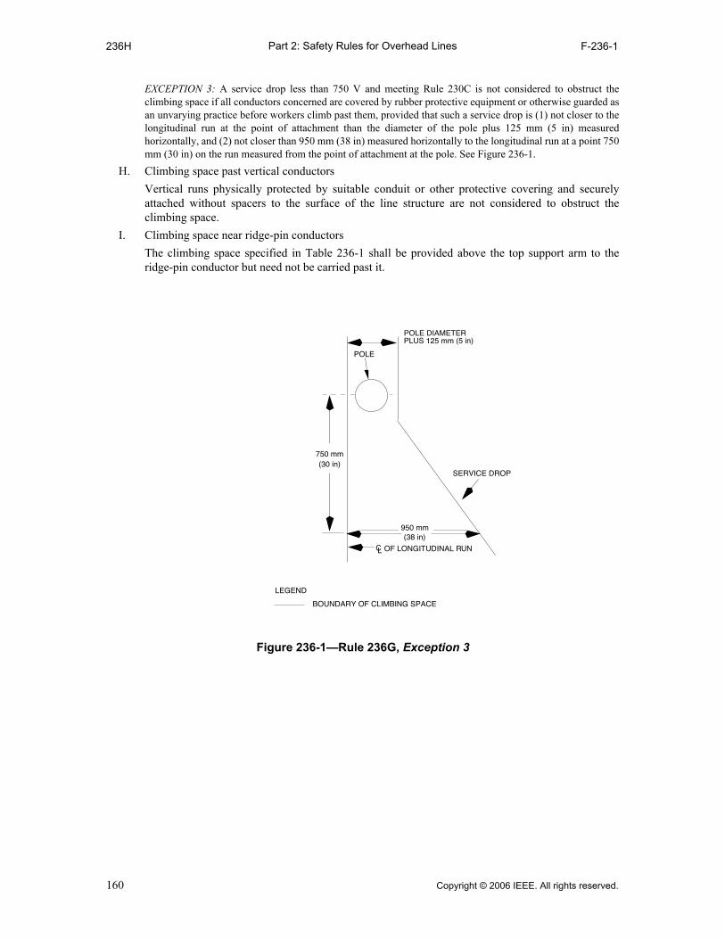
Part 2: Safety Rules for Overhead Lines236H F-236-1
EXCEPTION 3: A service drop less than 750 V and meeting Rule 230C is not considered to obstruct theclimbing space if all conductors concerned are covered by rubber protective equipment or otherwise guarded asan unvarying practice before workers climb past them, provided that such a service drop is (1) not closer to thelongitudinal run at the point of attachment than the diameter of the pole plus 125 mm (5 in) measuredhorizontally, and (2) not closer than 950 mm (38 in) measured horizontally to the longitudinal run at a point 750mm (30 in) on the run measured from the point of attachment at the pole. See Figure 236-1.
H. Climbing space past vertical conductors
Vertical runs physically protected by suitable conduit or other protective covering and securelyattached without spacers to the surface of the line structure are not considered to obstruct theclimbing space.
I. Climbing space near ridge-pin conductors
The climbing space specified in Table 236-1 shall be provided above the top support arm to theridge-pin conductor but need not be carried past it.
(38 in) CL OF LONGITUDINAL RUN
POLE
SERVICE DROP
750 mm(30 in)
POLE DIAMETERPLUS 125 mm (5 in)
LEGEND
BOUNDARY OF CLIMBING SPACE
950 mm
Figure 236-1—Rule 236G, Exception 3
160 Copyright © 2006 IEEE. All rights reserved.

Part 2: Safety Rules for Overhead LinesT-236-1 T-236-1
qThis relation of levels in general is not desirable and should be avoided.
wClimbing space shall be the same as required for the supply conductors immediately above, with a maximum of0.75 m (30 in) except that a climbing space of 0.41 m (16 in) across the line may be employed for communicationcables or conductors where the only supply conductors at a higher level are secondaries (0 to 750 V) supplyingairport or airway marker lights or crossing over the communication line and attached to the pole top or to a pole-topextension fixture.
eAttention is called to the operating requirements of Rules 441A and 446C, Part 4, of this Code.
Table 236-1— Horizontal clearance between conductors bounding the climbing space(All voltages are between the two conductors bounding the climbing space except for communication
conductors, which are voltage to ground. Where the two conductors are in different circuits, the voltage between conductors shall be the arithmetic sum of the voltages of each conductor to ground for a grounded
circuit, or phase to phase for an ungrounded conductor. See also Rule 236E.)
Character of conductors adjacent to
climbing space
Voltage of conductors
Horizontal clearance between conductors bounding the climbing space e
On structures used solely by On jointly used structures
Communication conductors
Supply conductors
Supply conductors
above communica-
tion conductors
Communication conductors
above supply conductorsq
(m) (in) (m) (in) (m) (in) (m) (in)
1. Communica-tionconductors
0 to 150 V 0.60 No require-ments
—w
0.60 No require-ments
Exceeding 150 V
24 recom-mended
—w
24 recom-mended
2. Supply cables meeting Rule 230C1
All voltages —w
No require-ments
3. Supply cables meeting Rule 230C2 or 3
All voltages — — 0.60 24 0.60 24 0.75 30
4. Open supply line conductors and supply cables meet-ing Rule 230D
0 to 750 V — — 0.60 24 0.60 24 0.75 30
750 V to 15 kV
— — 0.75 30 0.75 30 0.75 30
15 kV to28 kV
— — 0.90 36 0.90 36 0.90 36
28 kV to 38 kV
— — 1.00 40 1.00 40
38 kV to50 kV
— — 1.17 46 1.17 46
50 kV to 73 kV
— — 1.40 54 1.40 54
Exceeding 73 kV
— — >1.40 >54
Copyright © 2006 IEEE. All rights reserved. 161

Part 2: Safety Rules for Overhead Lines237 237E3
237. Working space
A. Location of working spaces
Working spaces shall be provided on the climbing face of the structure at each side of the climbingspace.
B. Dimensions of working spaces
1. Along the support arm
The working space shall extend from the climbing space to the outmost conductor position onthe support arm.
2. At right angles to the support arm
The working space shall have the same dimension as the climbing space (see Rule 236E). Thisdimension shall be measured horizontally from the face of the support arm.
3. Vertically
The working space shall have a height not less than that required by Rule 235 for the verticalseparation of line conductors carried at different levels on the same support.
C. Location of vertical and lateral conductors relative to working spaces
The working spaces shall not be obstructed by vertical or lateral conductors. Such conductors shallbe located on the opposite side of the pole from the climbing side or on the climbing side of the poleat a distance from the support arm at least as great as the width of climbing space required for thehighest voltage conductors concerned. Vertical conductors enclosed in suitable conduit may beattached on the climbing side of the structure.
D. Location of buckarms relative to working spaces
Buckarms may be used under any of the following conditions, provided the climbing space ismaintained. Climbing space may be obtained as in Rule 236F.
1. Standard height of working space
Lateral working space of the height required by Table 235-5 shall be provided between thecrossing or tap line conductors attached to the buckarm and the main line conductors. This maybe accomplished by increasing the spacing between the line support arms, as shown inFigure 237-1.
2. Reduced height of working space
Where no circuits exceeding 8.7 kV to ground or 15 kV line to line are involved and theclearances of Rules 235B1a and 235B1b are maintained, conductors supported on buckarmsmay be placed between line conductors having normal vertical spacing, even though suchbuckarms obstruct the normal working space, provided that a working space of not less than450 mm (18 in) in height is maintained either above or below line conductors and buckarmconductors.
EXCEPTION: The above working space may be reduced to 300 mm (12 in) if both of the followingconditions exist: (a) Not more than two sets of the line arms and buckarms are involved (b) Working conditions are rendered safe by providing rubber protective equipment or other suitable
devices to insulate and cover line conductors and equipment that are not being worked upon
E. Guarding of energized equipment
Exposed energized parts of equipment such as switches, circuit breakers, surge arresters, etc., shallbe enclosed or guarded if all of the following conditions apply:
1. The equipment is located below the top conductor support
2. The equipment is located on the climbing side of the structure
3. The requirements of Rule 441, Part 4, of this Code cannot be met
162 Copyright © 2006 IEEE. All rights reserved.

Part 2: Safety Rules for Overhead Lines237F 238E
F. Working clearances from energized equipment
All parts of equipment such as switches, fuses, transformers, surge arresters, luminaires and theirsupport brackets, etc., or other connections that may require operation or adjustment while energizedand exposed at such times, shall be so arranged with respect to each other, other equipment, verticaland lateral conductors, and portions of the supporting structure, including supporting platforms orstructural members, that in adjustment or operation no portion of the body, including the hands,need be brought closer to any exposed energized parts or conductors than permitted in Part 4,Rule 441 or 446 of this Code.
238. Vertical clearance between certain communications and supply facilities located on the same structure
A. Equipment
For the purpose of measuring clearances under this rule, equipment shall be taken to mean non-current-carrying metal parts of equipment, including metal supports for cables or conductors, andmetal support braces that are attached to metal supports or are less than 25 mm (1 in) fromtransformer cases or hangers that are not effectively grounded.
B. Clearances in general
Vertical clearances between supply conductors and communications equipment, betweencommunication conductors and supply equipment, and between supply and communicationsequipment shall be as specified in Table 238-1, except as provided in Rule 238C.
C. Clearances for span wires or brackets
Span wires or brackets carrying luminaires, traffic signals, or trolley conductors shall have at leastthe vertical clearances in millimeters or inches from communications equipment set forth inTable 238-2.
D. Clearance of drip loops of luminaire or traffic signal brackets
If a drip loop of conductors entering a luminaire bracket or traffic signal bracket from the surface ofthe structure is above a communication cable, the lowest point of the loop shall be at least 300 mm(12 in) above communication cable or through bolt.
EXCEPTION: The above clearance may be reduced to 75 mm (3 in) if the loop is covered by a suitablenonmetallic covering that extends at least 50 mm (2 in) beyond the loop.
E. Communication worker safety zone
The clearances specified in Rules 235C and 238 create a communication worker safety zonebetween the facilities located in the supply space and facilities located in the communication space,both at the structure and in the span between structures. Except as allowed by Rules 238C, 238D,and 239, no supply or communication facility shall be located in the communication worker safetyzone.
Figure 237-1—Obstruction of working space by buckarm
NOT LESS THAN450 mm (18 in)
CLEARANCE ASREQUIRED INRULE 235E1
Copyright © 2006 IEEE. All rights reserved. 163

Part 2: Safety Rules for Overhead LinesT-238-1 T-238-2
qWhere non-current-carrying parts of supply equipment are effectively grounded and the associated neutral meetingRule 230E1 or supply cables meeting Rule 230C1 (including the support brackets) are bonded to communicationmessengers at intervals meeting Rule 92C through out well-defined areas and where communication is at lowerlevels, clearances may be reduced to 0.75 m (30 in).
qThis may be reduced to 300 mm (12 in) for either span wires or metal parts of brackets at points 1.0 m (40 in) ormore from the structure surface.
Table 238-1—Vertical clearance between supply conductors and communications equipment, between communication conductors and supply equipment, and between
supply and communications equipment (Voltages are phase to ground for effectively grounded circuits and those other circuits where all ground faults are cleared by promptly de-energizing the faulted section, both initially and following subsequent
breaker operations. See the definitions section for voltages of other systems. See also Rule 238B.)
Supply voltage(kV)
Vertical clearance
(m) (in)
1. Grounded conductor and messenger hardware and supports
0.75 30
2. 0 to 8.7 1.00 40 q
3. Over 8.7 1.00 plus 0.01 per kVin excess of 8.7 kV
40 plus 0.4 per kV q
in excess of 8.7 kV
Table 238-2—Vertical clearance of span wires and brackets from communication lines (See also Rule 238C.)
Carrying luminaires or traffic signals Carrying trolley conductors
Not effectivelygrounded
Effectivelygrounded
Not effectivelygrounded
Effectivelygrounded
(mm) (in) (mm) (in) (mm) (in) (mm) (in)
Above communication support arms
500 20 q 500 20 q 500 20 q 500 20 q
Below communication support arms
1000 40 e 600 24 600 24 600 24
Above messengers carrying communication cables
500 20 q 100 4 300 12 100 4
Below messengers carrying communication cables
1000 40 r 100 4 300 12 100 4
From terminal box of communication cable
500 20 q 100 4 300 12 w 100 4
From communication brackets, bridle wire rings, or drive hooks
410 16 q 100 4 100 4 100 4
164 Copyright © 2006 IEEE. All rights reserved.

Part 2: Safety Rules for Overhead LinesT-238-2 239C
wWhere it is not practical to obtain a clearance of 300 mm (1 ft) from terminal boxes of communication cables, allmetal parts of terminals shall have the greatest possible clearance from fixtures or span wires including allsupporting screws and bolts of both attachments.
eThis may be reduced to 600 mm (24 in) for luminaires and traffic signals operating at less than 150 V to ground. rThis may be reduced to 500 mm (20 in) for luminaires and traffic signals operating at less than 150 V to ground.
239. Clearance of vertical and lateral facilities from other facilities and surfaces on the same supporting structure
Vertical and lateral conductors shall have the clearances required by this rule from other facilities orsurfaces on the same supporting structure.
A. General
1. Grounding conductors, surge-protection wires, neutral conductors meeting Rule 230E1,insulated communication conductors and cables, supply cables meeting Rule 230C1 or 350B,insulated supply cables of 0 to 750 V, or conduits may be placed directly on the supportingstructure. These conductors, wires, cables, and conduits shall be securely attached to thesurface of the structure. Cables not in conduit shall be installed in such a manner as to avoidabrasion at the point of attachment.
2. Installation of supply cable and communication cable in same duct or U-guard type covering
a. Supply cables 0 to 600 V may be installed together in the same duct or U-guard, if all ofthe cables are operated and maintained by the same utility.
b. Supply cables exceeding 600 V meeting Rule 230C1 may be installed together in the sameduct or U-guard if all of the cables are operated and maintained by the same utility.
c. Supply cables 0 to 600 V and supply cables exceeding 600 V meeting Rule 230C1 may beinstalled together in the same duct or U-guard if all of the cables are operated andmaintained by the same utility.
d. Supply cables shall not be installed in the same duct or U-guard with communicationcables unless all of the cables are operated and maintained by the same utility.
e. Communication cables may be installed together in the same duct or U-guard provided allutilities involved are in agreement.
3. Paired communication conductors in rings may be attached directly to a structure or messenger.
4. Insulated supply circuits of 600 V or less and not exceeding 5000 W may be placed in the samecable with control circuits with which they are associated.
5. The term nonmetallic covering as used in Rule 239 refers to material other than a cable jacketthat provides an additional barrier against physical contact.
6. Where guarding and protection are required by other rules, either conduit or U-guards may beused.
B. Location of vertical or lateral conductors relative to climbing spaces, working spaces, and pole steps
Vertical or lateral conductors shall be located so that they do not obstruct climbing spaces, or lateralworking spaces between line conductors at different levels, or interfere with the safe use of polesteps.
EXCEPTION: This rule does not apply to portions of the structure that workers do not ascend while theconductors in question are energized.
NOTE: See Rule 236H for vertical runs in conduit or other protective covering.
C. Conductors not in conduit
Conductors not encased in conduit shall have the same clearances from conduits as from othersurfaces of structures.
Copyright © 2006 IEEE. All rights reserved. 165
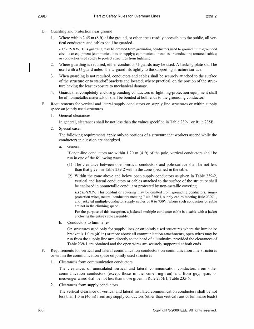
Part 2: Safety Rules for Overhead Lines239D 239F2
D. Guarding and protection near ground
1. Where within 2.45 m (8 ft) of the ground, or other areas readily accessible to the public, all ver-tical conductors and cables shall be guarded.
EXCEPTION: This guarding may be omitted from grounding conductors used to ground multi-groundedcircuits or equipment (communications or supply); communication cables or conductors; armored cables;or conductors used solely to protect structures from lightning.
2. Where guarding is required, either conduit or U-guards may be used. A backing plate shall beused with a U-guard unless the U-guard fits tightly to the supporting structure surface.
3. When guarding is not required, conductors and cables shall be securely attached to the surfaceof the structure or to standoff brackets and located, where practical, on the portion of the struc-ture having the least exposure to mechanical damage.
4. Guards that completely enclose grounding conductors of lightning-protection equipment shallbe of nonmetallic materials or shall be bonded at both ends to the grounding conductor.
E. Requirements for vertical and lateral supply conductors on supply line structures or within supplyspace on jointly used structures
1. General clearances
In general, clearances shall be not less than the values specified in Table 239-1 or Rule 235E.
2. Special cases
The following requirements apply only to portions of a structure that workers ascend while theconductors in question are energized.
a. General
If open-line conductors are within 1.20 m (4 ft) of the pole, vertical conductors shall berun in one of the following ways:
(1) The clearance between open vertical conductors and pole-surface shall be not lessthan that given in Table 239-2 within the zone specified in the table.
(2) Within the zone above and below open supply conductors as given in Table 239-2,vertical and lateral conductors or cables attached to the surface of the structure shallbe enclosed in nonmetallic conduit or protected by non-metallic covering.
EXCEPTION: This conduit or covering may be omitted from grounding conductors, surge-protection wires, neutral conductors meeting Rule 230E1, supply cables meeting Rule 230C1,and jacketed multiple-conductor supply cables of 0 to 750V, where such conductors or cableare not in the climbing space.
For the purpose of this exception, a jacketed multiple-conductor cable is a cable with a jacketenclosing the entire cable assembly.
b. Conductors to luminaires
On structures used only for supply lines or on jointly used structures where the luminairebracket is 1.0 m (40 in) or more above all communication attachments, open wires may berun from the supply line arm directly to the head of a luminaire, provided the clearances ofTable 239-1 are obtained and the open wires are securely supported at both ends.
F. Requirements for vertical and lateral communication conductors on communication line structuresor within the communication space on jointly used structures
1. Clearances from communication conductors
The clearances of uninsulated vertical and lateral communication conductors from othercommunication conductors (except those in the same ring run) and from guy, span, ormessenger wires shall be not less than those given in Rule 235E1, Table 235-6.
2. Clearances from supply conductors
The vertical clearance of vertical and lateral insulated communication conductors shall be notless than 1.0 m (40 in) from any supply conductors (other than vertical runs or luminaire leads)
166 Copyright © 2006 IEEE. All rights reserved.
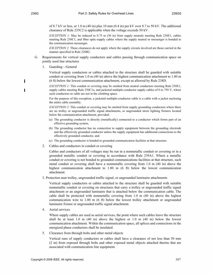
Part 2: Safety Rules for Overhead Lines239G 239G5
of 8.7 kV or less, or 1.0 m (40 in) plus 10 mm (0.4 in) per kV over 8.7 to 50 kV. The additionalclearance of Rule 235C2 is applicable when the voltage exceeds 50 kV.
EXCEPTION 1: May be reduced to 0.75 m (30 in) from supply neutrals meeting Rule 230E1, cablesmeeting Rule 230C1, and fiber optic-supply cables where the supply neutral or messenger is bonded tothe communication messenger.
EXCEPTION 2: These clearances do not apply where the supply circuits involved are those carried in themanner specified in Rule 220B2.
G. Requirements for vertical supply conductors and cables passing through communication space onjointly used line structures
1. Guarding—General
Vertical supply conductors or cables attached to the structure shall be guarded with suitableconduit or covering from 1.0 m (40 in) above the highest communication attachment to 1.80 m(6 ft) below the lowest communication attachment, except as allowed by Rule 238D.
EXCEPTION 1: This conduit or covering may be omitted from neutral conductors meeting Rule 230E1,supply cables meeting Rule 230C1a, and jacketed multiple-conductor supply cables of 0 to 750 V, wheresuch conductors or cable are not in the climbing space.
For the purpose of this exception, a jacketed multiple-conductor cable is a cable with a jacket enclosingthe entire cable assembly.
EXCEPTION 2: This conduit or covering may be omitted from supply grounding conductors where thereare no trolley or ungrounded traffic signal attachments, or ungrounded street lighting fixtures locatedbelow the communication attachment, provided:
(a) The grounding conductor is directly (metallically) connected to a conductor which forms part of aneffective grounding system,
(b) The grounding conductor has no connection to supply equipment between the grounding electrodeand the effectively grounded conductor unless the supply equipment has additional connections to theeffectively grounded conductor, and
(c) The grounding conductor is bonded to grounded communication facilities at that structure.
2. Cables and conductors in conduit or covering
Cables and conductors of all voltages may be run in a nonmetallic conduit or covering or in agrounded metallic conduit or covering in accordance with Rule 239A1. Where a metallicconduit or covering is not bonded to grounded communications facilities at that structure, suchmetal conduit or covering shall have a nonmetallic covering from 1.0 m (40 in) above thehighest communication attachment to 1.80 m (6 ft) below the lowest communicationattachment.
3. Protection near trolley, ungrounded traffic signal, or ungrounded luminaire attachments
Vertical supply conductors or cables attached to the structure shall be guarded with suitablenonmetallic conduit or covering on structures that carry a trolley or ungrounded traffic signalattachment or an ungrounded luminaire that is attached below the communication cable. Thecable shall be protected with nonmetallic covering from 1.0 m (40 in) above the highestcommunication wire to 1.80 m (6 ft) below the lowest trolley attachment or ungroundedluminaire fixture or ungrounded traffic signal attachment.
4. Aerial services
Where supply cables are used as aerial services, the point where such cables leave the structureshall be at least 1.0 m (40 in) above the highest or 1.0 m (40 in) below the lowestcommunication attachment. Within the communication space, all splices and connections in theenergized phase conductors shall be insulated.
5. Clearance from through bolts and other metal objects
Vertical runs of supply conductors or cables shall have a clearance of not less than 50 mm(2 in) from exposed through bolts and other exposed metal objects attached thereto that areassociated with communication line equipment.
Copyright © 2006 IEEE. All rights reserved. 167

Part 2: Safety Rules for Overhead Lines239H 239J1
EXCEPTION: Vertical runs of effectively grounded supply conductors may have a clearance of 25 mm(1 in).
H. Requirements for vertical communication conductors passing through supply space on jointly usedstructures
All vertical runs of communication conductors passing through supply space shall be installed asfollows:
1. Metal-sheathed communication cables
Vertical runs of metal-sheathed communication cables shall be covered with suitablenonmetallic material, where they pass trolley feeders or other supply line conductors. Thisnonmetallic covering shall extend from a point 1.0 m (40 in) above the highest trolley feedersor other supply conductors, to a point 1.80 m (6 ft) below the lowest trolley feeders or othersupply conductors, but need not extend below the top of any mechanical protection that may beprovided near the ground.
EXCEPTION 1: Communication cables may be run vertically on the pole through space occupied byrailroad signal supply circuits in the lower position, as permitted in Rule 220B2, without covering withinthe supply space.
EXCEPTION 2: Covering is not required in the supply space on metallic or concrete supportingstructures.
2. Communication conductors
Vertical runs of insulated communication conductors shall be covered with suitablenonmetallic material, to the extent required for metal-sheathed communication cables in Rule239H1, where such conductors pass trolley feeders or supply conductors.
EXCEPTION 1: Communication conductors may be run vertically on the structure through spaceoccupied by railroad-signal supply circuits in the lower position, as permitted in Rule 220B2, withoutcovering within the supply space.
EXCEPTION 2: Covering is not required in the supply space on metallic or concrete supportingstructures.
3. Communication grounding conductors
Vertical communication grounding conductors shall be covered with suitable nonmetallicmaterial between points at least 1.80 m (6 ft) below and 1.0 m (40 in) above any trolley feedersor other supply line conductors by which they pass.
EXCEPTION 1: Communication grounding conductors may be run vertically on the structure thoughspace occupied by railroad-signal supply circuits in the lower position, as permitted in Rule 220B2,without covering within the supply space.
EXCEPTION 2: Covering is not required in the supply space on metallic or concrete supportingstructures.
4. Clearance from through bolts and other metal objects
Vertical runs of communication conductors or cables shall have a clearance of one-eighth ofthe pole circumference but not less than 50 mm (2 in) from exposed through bolts and otherexposed metal objects attached thereto that are associated with supply line equipment.
EXCEPTION: Vertical runs of effectively grounded communication cables may have a clearance of25 mm (1 in).
I. Operating rods
Effectively grounded or insulated operating rods of switches are permitted to pass through thecommunication space, but shall be located outside of the climbing space.
J. Additional rules for standoff brackets
1. Standoff brackets may be used to support the conduit(s). Cable insulation appropriate for theintended service is required; non-metallic conduit shall not be used to meet basic insulationrequirements.
NOTE: See Rule 217A2.
168 Copyright © 2006 IEEE. All rights reserved.

Part 2: Safety Rules for Overhead Lines239J2 T-239-1(in)
2. Standoff brackets may be used to support the following types of cable enclosed within a singleouter jacket or sheath (cable only without conduit):
a. Communication
b. 230C1a supply (any voltage)
c. Supply less than 750 V
NOTE: See Rule 217A2.
m
in
Table 239-1—Clearance of open vertical and lateral conductors(Circuit phase-to-phase voltage. See also Rules 239E1 and 239E2b.)
Clearance of open vertical and lateral conductors
0 to 8.7 kV(mm)
Over 8.7 to 50 kV(mm)
Over 50 kV r
(mm)
From surfaces of supports 75 q w 75 plus 5 per kVin excess of 8.7 kV
280 plus 5 per kVin excess of 50 kV
From span, guy, and messenger wires t 150 150 plus 10 per kVin excess of 8.7 kV e
580 plus 10 per kVin excess of 50 kV e
qA neutral conductor meeting Rule 230E1 may be attached directly to the structure surface. wFor supply circuits of 0 to 750 V, this clearance may be reduced to 25 mm. eMultiplier may be reduced to 6.5 mm/kV for anchor guys. rThe additional clearance for voltages in excess of 50 kV specified in Table 239-1 shall be increased 3% for each
300 m in excess of 1000 m above mean sea level.tThese clearances may be reduced by not more than 25% to a guy insulator, provided that full clearance is
maintained to its metallic end fittings and the guy wires. The clearance to an insulated section of a guy betweentwo insulators may be reduced by not more than 25% provided that full clearance is maintained to the uninsulatedportion of the guy.
Table 239-1—Clearance of open vertical and lateral conductors(Circuit Phase-to-Phase Voltage. See also Rules 239E1 and 239E2b.)
Clearance of open vertical and lateral conductors
0 to 8.7 kV(in)
Over 8.7 to 50 kV(in)
Over 50 kV r
(in)
From surfaces of supports 3 q w 3 plus 0.2 per kVin excess of 8.7 kV
11 plus 0.2 per kVin excess of 50 kV
From span, guy, and messenger wires t 6 6 plus 0.4 per kVin excess of 8.7 kV e
23 plus 0.4 per kVin excess of 50 kV e
qA neutral conductor meeting Rule 230E1 may be attached directly to the structure surface. wFor supply circuits of 0 to 750 V, this clearance may be reduced to 1 in. eMultiplier may be reduced to 0.25 in/kV for anchor guys. rThe additional clearance for voltages in excess of 50 kV specified in Table 239-1 shall be increased 3% for each
1000 ft in excess of 3300 ft above mean sea level.tThese clearances may be reduced by not more than 25% to a guy insulator, provided that full clearance is
maintained to its metallic end fittings and the guy wires. The clearance to an insulated section of a guy betweentwo insulators may be reduced by not more than 25% provided that full clearance is maintained to the uninsulatedportion of the guy.
Copyright © 2006 IEEE. All rights reserved. 169

Part 2: Safety Rules for Overhead LinesT-239-2(m) T-239-2(in)
m
in
Table 239-2—Clearance between open vertical conductors and pole surface[Voltages are phase to ground for effectively grounded circuits and those other circuits where all ground faults
are cleared by promptly de-energizing the faulted section, both initially and following subsequent breaker operations. See the definitions section for voltages of other systems.
See also Rules 239E2a(1) and 239E2a(2).]
Voltage(kV)
Distance above and below open supplyconductors where clearances apply
(m)
Clearance between verticalconductor and pole surface
(mm)
0 to 22q 1.80 480
22 to 30 1.80 560
30 to 50 1.80 760
qDoes not include neutral conductors meeting Rule 230E1.
Table 239-2—Clearance between open vertical conductors and pole surface [Voltages are phase to ground for effectively grounded circuits and those other circuits where all ground faults
are cleared by promptly de-energizing the faulted section, both initially and following subsequent breaker operations. See the definitions section for voltages of other systems.
See also Rules 239E2a(1) and 239E2a(2).]
Voltage(kV)
Distance above and below open supplyconductors where clearances apply
(ft)
Clearance between verticalconductor and pole surface
(in)
0 to 22 q 6 19
22 to 30 6 22
30 to 50 6 30
qDoes not include neutral conductors meeting Rule 230E1.
170 Copyright © 2006 IEEE. All rights reserved.

Part 2: Safety Rules for Overhead Lines240 241D
Section 24.Grades of construction
240. General
A. The grades of construction are specified in this section on the basis of the required strengths for safety.Where two or more conditions define the grade of construction required, the grade used shall be thehighest one required by any of the conditions.
B. For the purposes of this section, the voltage values for direct-current circuits shall be consideredequivalent to the rms values for alternating-current circuits.
241. Application of grades of construction to different situations
A. Supply cables
For the purposes of these rules, supply cables are classified by two types as follows:
Type 1—Supply cables conforming to Rule 230C1, 230C2, or 230C3 shall be installed inaccordance with Rule 261I.
Type 2—All other supply cables are required to have the same grade of construction as open-wireconductors of the same voltage.
B. Order of grades
The relative order of grades for supply and communication conductors and supporting structures isB, C, and N, with Grade B being the highest.
C. At crossings
Wires, conductors, or other cables of one line are considered to be at crossings when they cross overanother line, whether or not on a common supporting structure, or when they cross over or overhanga railroad track, the traveled way of a limited access highway, or navigable waterways requiringwaterway crossing permits. Joint-use or collinear construction in itself is not considered to be atcrossings.
1. Grade of upper line
Conductors and supporting structures of a line crossing over another line shall have the gradeof construction specified in Rules 241C3, 242, and 243.
2. Grade of lower line
Conductors and supporting structures of a line crossing under another line need only have thegrades of construction that would be required if the line at the higher level were not there.
3. Multiple crossings
a. Where a line crosses in one span over two or more other lines, or where one line crossesover a span of a second line, which span in turn crosses a span of a third line, the grade ofconstruction of the uppermost line shall be not less than the highest grade that would berequired of either one of the lower lines when crossing the other lower line.
b. Where communication conductors cross over supply conductors and railroad tracks in thesame span, the grades of construction shall be in accordance with Grade B construction. Itis recommended that the placing of communication conductors above supply conductorsgenerally be avoided unless the supply conductors are trolley-contact conductors and theirassociated feeders.
D. Conflicts (see Section 2, structure conflict)
The grade of construction of the conflicting structure shall be as required by Rule 243A4.
Copyright © 2006 IEEE. All rights reserved. 171
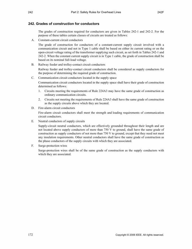
Part 2: Safety Rules for Overhead Lines242 242F
242. Grades of construction for conductors
The grades of construction required for conductors are given in Tables 242-1 and 242-2. For thepurpose of these tables certain classes of circuits are treated as follows:
A. Constant-current circuit conductors
The grade of construction for conductors of a constant-current supply circuit involved with acommunication circuit and not in Type 1 cable shall be based on either its current rating or on theopen-circuit voltage rating of the transformer supplying such circuit, as set forth in Tables 242-1 and242-2. When the constant current supply circuit is in Type 1 cable, the grade of construction shall bebased on its nominal full-load voltage.
B. Railway feeder and trolley-contact circuit conductors
Railway feeder and trolley-contact circuit conductors shall be considered as supply conductors forthe purpose of determining the required grade of construction.
C. Communication circuit conductors located in the supply space
Communication circuit conductors located in the supply space shall have their grade of constructiondetermined as follows:
1. Circuits meeting the requirements of Rule 224A3 may have the same grade of construction asordinary communication circuits.
2. Circuits not meeting the requirements of Rule 224A3 shall have the same grade of constructionas the supply circuits above which they are located.
D. Fire-alarm circuit conductors
Fire-alarm circuit conductors shall meet the strength and loading requirements of communicationcircuit conductors.
E. Neutral conductors of supply circuits
Supply-circuit neutral conductors, which are effectively grounded throughout their length and arenot located above supply conductors of more than 750 V to ground, shall have the same grade ofconstruction as supply conductors of not more than 750 V to ground, except that they need not meetany insulation requirements. Other neutral conductors shall have the same grade of construction asthe phase conductors of the supply circuits with which they are associated.
F. Surge-protection wires
Surge-protection wires shall be of the same grade of construction as the supply conductors withwhich they are associated.
172 Copyright © 2006 IEEE. All rights reserved.

Part 2: Safety Rules for Overhead LinesT-242-1 T-242-1
Table 242-1— Grades of construction for supply conductors alone, at crossing,
or on the same structures with other conductors (The voltages listed in this table are phase-to-ground values for: effectively grounded ac circuits, two-wire
grounded circuits, or center-grounded dc circuits; otherwise phase-to-phase values shall be used. The grade of construction for supply conductors, as indicated across the top of the table, shall also meet the
requirements for any lines at lower levels except when otherwise noted.)
Conductors, tracks, and rights-of-way at lower levels
Supply conductors at higher levels q
Constant-potential supply conductorsConstant-
current supply
conductors
Commu-nication
conductors located in the supply
space
0 to 750 V 751 V to 8.7
kVExceeding 8.7
kV
Open or
cable Open Cable Open Cable Open CableOpen or
cable
Exclusive private rights-of-way N N w N N w N w B, C, or N;see Rule 242A
C or N;see Rule
242CCommon or public rights-of-way
N C N C e C
Railroad tracks, limited-access high-ways, a and navigable water-ways requiring waterway crossing permits
B B B B B B B B
Constant-potential supply conductors 0 to 750 V, open or cable
N C N C e C
B, C, or N;see Rule 242A
B, C, or N;see Rule
242C
750 V to 8.7 kVOpen
Cr C C C e C
Cable N C N C e C
Exceeding 8.7 kVOpen
Br B B C e C
Cable Cr C N C e C
Constant-current supply conductors: open or cable B, C, or N; see Rule 242A B, C, or N; see
Rule 242A
B, C, or N; see Rules 242A and
242C
Communication conductors: open or cable, located in the supply space o
B, C, or N; see Rule 242CB, C, or N; see Rules 242A and
242C
B, C, or N; see Rule
242C
Communication conductor: open or cable t
N Byu C Bu C Bui C or N; see
Rule 242A
B, C, or N;see Rule
242C
Copyright © 2006 IEEE. All rights reserved. 173

Part 2: Safety Rules for Overhead LinesT-242-1 T-242-1
qThe words open and cable appearing in the headings have the following meanings as applied to supply conductors:cable means the Type 1 cables described in Rule 241A; open means Type 2 cables described in Rule 241A and openwire.
wLines that can fall outside the exclusive private rights-of-way shall comply with the grades specified for lines not onexclusive private rights-of-way.
eSupply conductors shall meet the requirements of Grade B construction if the supply circuits will not be promptlyde-energized, both initially and following subsequent breaker operations, in the event of a contact with lower supplyconductors or other grounded objects.
rIf the wires are service drops, they may have Grade N sizes and tensions as set forth in Table 263-2. tGrade N construction may be used where the communication conductors consist only of not more than one insulated
twisted-pair or parallel-lay conductor, or where service drops only are involved.yGrade C construction may be used if the voltage does not exceed 5.0 kV phase to phase or 2.9 kV phase to ground.uThe supply conductors need only meet the requirements of Grade C construction if both of the following conditions
are fulfilled: (a) The supply voltage will be promptly removed from the communications plant by de-energization or other means,
both initially and following subsequent circuit-breaker operations in the event of a contact with thecommunications plant.
(b) The voltage and current impressed on the communications plant in the event of a contact with the supply conductors are not in excess of the safe operating limit of the communications-protective devices.
iGrade C construction may be used if the current cannot exceed 7.5 A or the open-circuit voltage of the transformersupplying the circuit does not exceed 2.9 kV.
oCommunication circuits located below supply conductors shall not affect the grade of construction of the supplycircuits.
aThere is no intent to require Grade B over ordinary streets and highways.
174 Copyright © 2006 IEEE. All rights reserved.
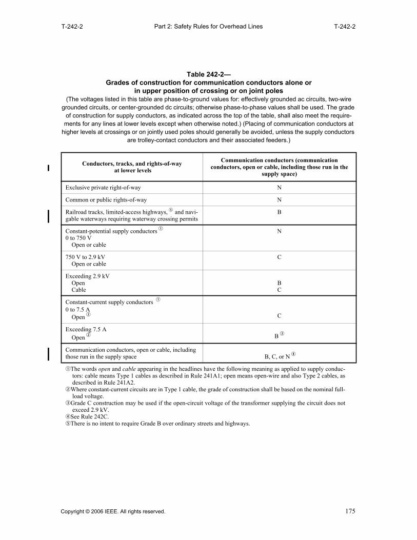
Part 2: Safety Rules for Overhead LinesT-242-2 T-242-2
Table 242-2— Grades of construction for communication conductors alone or
in upper position of crossing or on joint poles(The voltages listed in this table are phase-to-ground values for: effectively grounded ac circuits, two-wire
grounded circuits, or center-grounded dc circuits; otherwise phase-to-phase values shall be used. The grade of construction for supply conductors, as indicated across the top of the table, shall also meet the require-ments for any lines at lower levels except when otherwise noted.) (Placing of communication conductors at
higher levels at crossings or on jointly used poles should generally be avoided, unless the supply conductors are trolley-contact conductors and their associated feeders.)
Conductors, tracks, and rights-of-way at lower levels
Communication conductors (communication conductors, open or cable, including those run in the
supply space)
Exclusive private right-of-way N
Common or public rights-of-way N
Railroad tracks, limited-access highways, t and navi-gable waterways requiring waterway crossing permits
B
Constant-potential supply conductors q
0 to 750 VOpen or cable
N
750 V to 2.9 kVOpen or cable
C
Exceeding 2.9 kVOpenCable
BC
Constant-current supply conductors q
0 to 7.5 AOpen w C
Exceeding 7.5 AOpen w B e
Communication conductors, open or cable, including those run in the supply space B, C, or N r
qThe words open and cable appearing in the headlines have the following meaning as applied to supply conduc-tors: cable means Type 1 cables as described in Rule 241A1; open means open-wire and also Type 2 cables, asdescribed in Rule 241A2.
wWhere constant-current circuits are in Type 1 cable, the grade of construction shall be based on the nominal full-load voltage.
eGrade C construction may be used if the open-circuit voltage of the transformer supplying the circuit does notexceed 2.9 kV.
rSee Rule 242C.tThere is no intent to require Grade B over ordinary streets and highways.
Copyright © 2006 IEEE. All rights reserved. 175

Part 2: Safety Rules for Overhead Lines243 243C5
243. Grades of construction for line supports
A. Structures
The grade of construction shall be that required for the highest grade of conductors supported exceptas modified by the following:
1. The grade of construction of jointly used structures, or structures used only by communicationlines, need not be increased merely because the communication wires carried on such structurescross over trolley-contact conductors of 0 to 750 V to ground.
2. Structures carrying supply service drops of 0 to 750 V to ground shall have a grade of construc-tion not less than that required for supply line conductors of the same voltage.
3. Where the communication lines cross over supply conductors and a railroad in the same spanand Grade B is required by Rule 241C3b for the communication conductors, due to the pres-ence of railroad tracks, the grade of the structures shall be B.
4. The grade of construction required for a conflicting structure (first circuit) shall be determinedfrom the requirements of Rule 242 for crossings. The conflicting structure’s conductors (firstcircuit) shall be assumed to cross the other circuit’s conductors (second circuit) for the pur-poses of determining the grade of construction required for the conflicting structure.
NOTE: The resulting structure grade requirement could result in a higher grade of construction for thestructure than for the conductors carried thereon.
B. Crossarms and support arms
The grade of construction shall be that required for the highest grade of conductors carried by thearm concerned except as modified by the following:
1. The grade of construction of arms carrying only communication conductors need not beincreased merely because the conductors cross over trolley-contact conductors of 0 to 750 V toground.
2. Arms carrying supply service drops of 0 to 750 V to ground shall have a grade of constructionnot less than that required for supply line conductors of the same voltage.
3. Where communication lines cross over supply conductors and a railroad in the same span andGrade B is required by Rule 241C3b for the communication conductors due to the presence ofrailroad tracks, the grade of the arm shall be B.
C. Pins, armless construction brackets, insulators, and conductor fastenings
The grade of construction for pins, armless construction brackets, insulators, and conductorfastenings shall be that required for the conductor concerned except as modified by the following:
1. The grade of construction need not be increased merely because the supported conductors crossover trolley-contact conductors of 0 to 750 V to ground.
2. Supply service drops of 0 to 750 V to ground require only the same grade of construction assupply line conductors of the same voltage.
3. When Grade B construction is required by Rule 241C3b for the communication conductors dueto the presence of railroad tracks, Grade B construction shall be used when supporting commu-nication lines that cross over supply conductors and a railroad in the same span.
4. When communication conductors are required to meet Grade B or C, only the requirements formechanical strength for these grades are required.
5. Insulators for use on open conductor supply lines shall meet the requirements of Section 27 forall grades of construction.
176 Copyright © 2006 IEEE. All rights reserved.

Part 2: Safety Rules for Overhead Lines250 250C
Section 25.Loadings for Grades B and C
250. General loading requirements and maps
A. General
1. It is necessary to assume the wind and ice loads that may occur on a line. Three weather load-ings are specified in Rules 250B, 250C, and 250D. Where all three rules apply, the requiredloading shall be the one that has the greatest effect.
2. Where construction or maintenance loads exceed those imposed by Rule 250A1, the assumedloadings shall be increased accordingly. When temporary loads, such as lifting of equipment,stringing operations, or a worker on a structure or its component, are to be imposed on astructure or component, the strength of the structure or component should be taken into accountor other provisions should be made to limit the likelihood of adverse effects of structure orcomponent failure.
NOTE: Other provisions could include cranes that can support the equipment loads, guard poles and spot-ters with radios, and stringing equipment capable of promptly halting stringing operations.
3. It is recognized that loadings actually experienced in certain areas in each of the loading dis-tricts may be greater, or in some cases, may be less than those specified in these rules. In theabsence of a detailed loading analysis, using the same respective statistical methodologies usedto develop the maps in Rule 250C or 250D, no reduction in the loadings specified therein shallbe made without the approval of the administrative authority.
4. The structural capacity provided by meeting the loading and strength requirements of Sections25 and 26 provides sufficient capability to resist earthquake ground motions.
B. Combined ice and wind district loading
Three general degrees of district loading due to weather conditions are recognized and aredesignated as heavy, medium, and light loading. Figure 250-1 shows the districts where theseloadings apply.
NOTE: The localities are classified in the different loading districts according to the relative simultaneousprevalence of the wind velocity and thickness of ice that accumulates on wires. Light loading is for placeswhere little, if any, ice accumulates on wires.
Table 250-1 shows the radial thickness of ice and the wind pressures to be used in calculating loads.Ice is assumed to weigh 913 kg/m3 (57 lb/ft3).
C. Extreme wind loading
If no portion of a structure or its supported facilities exceeds 18 m (60 ft) above ground or waterlevel, the provisions of this rule are not required, except as specified in Rule 261A1c, 261A2e, or261A3d. Where a structure or its supported facilities exceeds 18 m (60 ft) above ground or waterlevel the structure and its supported facilities shall be designed to withstand the extreme wind loadassociated with the Basic Wind Speed, as specified by Figure 250-2. The wind pressures calculatedshall be applied to the entire structure and supported facilities without ice. The following formulashall be used to calculate wind load.
Load in newtons = 0.613 ⋅ (Vm/s)2 ⋅ kz ⋅ GRF ⋅ I ⋅ Cf ⋅ A(m2)
Load in pounds = 0.00256 ⋅ (Vmi/h)2 ⋅ kz ⋅ GRF ⋅ I ⋅ Cf ⋅ A(ft2)
Copyright © 2006 IEEE. All rights reserved. 177

Part 2: Safety Rules for Overhead Lines250C1 250C2
where
The wind pressure parameters (kz, V, and GRF) are based on open terrain with scattered obstructions(Exposure Category C as defined in ASCE 7-05). Exposure Category C is the basis of the NESCextreme wind criteria. Topographical features such as ridges, hills, and escarpments may increasethe wind loads on site-specific structures. A Topographic Factor, Kzt, from ASCE 7-05, may be usedto account for these special cases.
1. Velocity pressure exposure coefficient, kz
The velocity pressure exposure coefficient, kz, is based on the height, h, to the center-of-pressure of the wind area for the following load applications:
a. kz for the structure is based on 0.67 of the total height, h, of the structure above groundline.
NOTE: In Table 250-2, for h ≤ 75 m (250 ft), the structure kz values are adjusted for the wind load tobe determined at the center-of-pressure of the structure assumed to be at 0.67 h. The wind pressure isassumed uniformly distributed over the structure face normal to the wind.
b. kz for the wire is based on the height, h, of the wire at the structure.
NOTE: In special terrain conditions (i.e., mountainous terrain and canyon) where the height of thewire aboveground at mid-span may be substantially higher than at the structure, engineeringjudgment may be used in determining an appropriate value for the wire kz.
c. kz for a specific structure location or component is based on the height, h, to the center-of-pressure of the wind area being considered.
The selected values of kz, are tabulated in Table 250-2. When h is > 75 m (250 ft), the formulasshall be used to determine a kz value.
2. Gust response factor, GRF
Selected values of the structure and wire gust response factors are tabulated in Table 250-3.The structure gust response factor, GRF, is determined using the total structure height, h. Thewire gust response factor is determined using the height of the wire at the structure, h, and thedesign wind span, L. The structure and wire gust response factors may also be determinedusing the formulas in Table 250-3. For values of h > 75 m (250 ft) and L > 600 m (2000 ft) theGRF shall be determined using the formulas in Table 250-3. In special terrain conditions (i.e.,mountainous terrain and canyon) where the height of the conductor aboveground at mid-spanmay be substantially higher than at the attachment point, engineering judgment may be used indetermining an appropriate value for the wire GRF. Wire attachment points that are 18 m (60 ft)or less above ground or water level must be considered if the total structure height is greaterthan 18 m (60 ft) above ground or water.
0.613 Velocity-pressure numerical coefficient reflects the mass density of airfor the standard atmosphere, i.e., temperature of 15 °C (59 °F) and sealevel pressure of 760 mm (29.92 in) of mercury. The numericalcoefficient 0.613 metric (0.00256 customary) shall be used except wheresufficient climatic data are available to justify the selection of a differentvalue of this factor for a design application.
0.00256
kz Velocity pressure exposure coefficient, as defined in Rule 250C1, Table250-2
V Basic wind speed, 3 s gust wind speed in m/s at 10 m (mi/h at 33 ft)aboveground, Figure 250-2
GRF Gust response factor, as defined in Rule 250C2I Importance factor, 1.0 for utility structures and their supported facilitiesCf Force coefficient (shape factor). As defined in Rule 252B.A Projected wind area, m2 (ft2)
178 Copyright © 2006 IEEE. All rights reserved.

Part 2: Safety Rules for Overhead Lines250D F-250-1
When calculating a wind load at a specific structure location, the structure gust response factor,GRF, determined using the total structure height, h, shall be used. The gust response factor,GRF, to be used on components, such as antennas, transformers, etc., shall be the structure gustresponse factor.
D. Extreme ice with concurrent wind loading
If no portion of a structure or its supported facilities exceeds 18 m (60 ft) above ground or waterlevel, the provisions of this rule are not required. Where a structure or its supported facilitiesexceeds 18 m (60 ft) above ground or water level, the structure and its supported facilities shall bedesigned to withstand the ice and wind load associated with the Uniform Ice Thickness andConcurrent Wind Speed, as specified by Figure 250-3. The wind pressures for the concurrent windspeed shall be as indicated in Table 250-4. The wind pressures calculated shall be applied to theentire structure and supported facilities without ice and to the iced wire diameter determined inaccordance with Rule 251. Ice is assumed to weigh 913 kg/m3 (57 lb/ft3).
1. For Grade B, the radial thickness of ice from Figure 250-3 shall be multiplied by a factor of1.00.
2. For Grade C, the radial thickness of ice from Figure 250-3 shall be multiplied by a factor of0.80.
3. The concurrent wind shall be applied to the projected area resulting from Rules 250D1 and250D2 multiplied by a factor of 1.00.
Figure 250-1—General loading map of United States with respect to loading of overhead lines
Copyright © 2006 IEEE. All rights reserved. 179

Part 2: Safety Rules for Overhead LinesF-250-2(a) F-250-2(a)
NOTE: Figure 250-2(a) reprinted with the permission of ASCE Publications, 1801 Alexander Bell Dr., Reston,VA 20191 from ASCE 7-05, Minimum Design Loads for Buildings and Other Structures. Copyright © 2005.
Figure 250-2(a)—Basic wind speeds
180 Copyright © 2006 IEEE. All rights reserved.
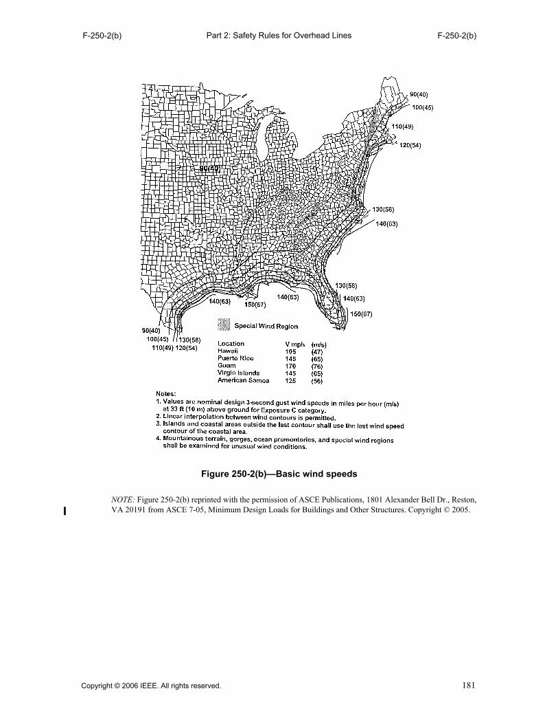
Part 2: Safety Rules for Overhead LinesF-250-2(b) F-250-2(b)
NOTE: Figure 250-2(b) reprinted with the permission of ASCE Publications, 1801 Alexander Bell Dr., Reston,VA 20191 from ASCE 7-05, Minimum Design Loads for Buildings and Other Structures. Copyright © 2005.
Figure 250-2(b)—Basic wind speeds
Copyright © 2006 IEEE. All rights reserved. 181

Part 2: Safety Rules for Overhead LinesF-250-2(c) F-250-2(d)
NOTE: Figure 250-2(c) reprinted with the permission of ASCE Publications, 1801 Alexander Bell Dr., Reston,VA 20191 from ASCE 7-05, Minimum Design Loads for Buildings and Other Structures. Copyright © 2005.
NOTE: Figure 250-2(d) reprinted with the permission of ASCE Publications, 1801 Alexander Bell Dr., Reston,VA 20191 from ASCE 7-05, Minimum Design Loads for Buildings and Other Structures. Copyright © 2005.
Figure 250-2(c)—Western Gulf of Mexico hurricane coastline
Figure 250-2(d)—Eastern Gulf of Mexico and southeastern US hurricane coastline
182 Copyright © 2006 IEEE. All rights reserved.

Part 2: Safety Rules for Overhead LinesF-250-2(e) F-250-2(e)
NOTE: Figure 250-2(e) reprinted with the permission of ASCE Publications, 1801 Alexander Bell Dr., Reston,VA 20191 from ASCE 7-05, Minimum Design Loads for Buildings and Other Structures. Copyright © 2005.
Figure 250-2(e)—Mid and northern Atlantic hurricane coastline
Copyright © 2006 IEEE. All rights reserved. 183

Part 2: Safety Rules for Overhead LinesF-250-3(a) F-250-3(a)
NOTE: Figure 250-3(a) reprinted with the permission of ASCE Publications, 1801 Alexander Bell Dr., Reston,VA 20191 from ASCE 7-05, Minimum Design Loads for Buildings and Other Structures. Copyright © 2005.
Figure 250-3(a)—Uniform ice thickness with concurrent wind
Fig. 250-3(e)
Fig. 250-3(d)
184 Copyright © 2006 IEEE. All rights reserved.

Part 2: Safety Rules for Overhead LinesF-250-3(b) F-250-3(b)
NOTE: Figure 250-3(b) reprinted with the permission of ASCE Publications, 1801 Alexander Bell Dr., Reston,VA 20191 from ASCE 7-05, Minimum Design Loads for Buildings and Other Structures. Copyright © 2005.
Figure 250-3(b)—Uniform ice thickness with concurrent wind
Copyright © 2006 IEEE. All rights reserved. 185
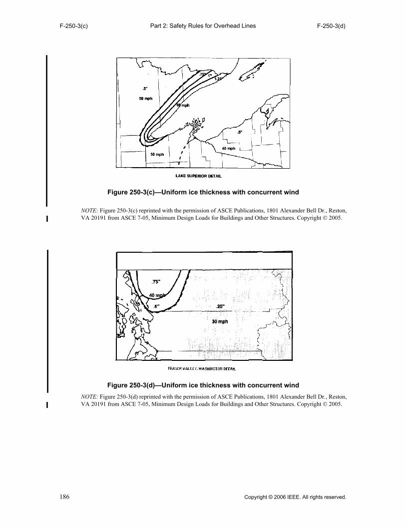
Part 2: Safety Rules for Overhead LinesF-250-3(c) F-250-3(d)
NOTE: Figure 250-3(c) reprinted with the permission of ASCE Publications, 1801 Alexander Bell Dr., Reston,VA 20191 from ASCE 7-05, Minimum Design Loads for Buildings and Other Structures. Copyright © 2005.
NOTE: Figure 250-3(d) reprinted with the permission of ASCE Publications, 1801 Alexander Bell Dr., Reston,VA 20191 from ASCE 7-05, Minimum Design Loads for Buildings and Other Structures. Copyright © 2005.
Figure 250-3(c)—Uniform ice thickness with concurrent wind
Figure 250-3(d)—Uniform ice thickness with concurrent wind
186 Copyright © 2006 IEEE. All rights reserved.

Part 2: Safety Rules for Overhead LinesF-250-3(e) F-250-3(e)
NOTE: Figure 250-3(e) reprinted with the permission of ASCE Publications, 1801 Alexander Bell Dr., Reston,VA 20191 from ASCE 7-05, Minimum Design Loads for Buildings and Other Structures. Copyright © 2005.
Figure 250-3(e)—Uniform ice thickness with concurrent wind
Copyright © 2006 IEEE. All rights reserved. 187

Part 2: Safety Rules for Overhead LinesF-250-3(f) F-250-3(f)
NOTE: Figure 250-3(f) reprinted with the permission of ASCE Publications, 1801 Alexander Bell Dr., Reston,VA 20191 from ASCE 7-05, Minimum Design Loads for Buildings and Other Structures. Copyright © 2005.
Figure 250-3(f)—Uniform ice thickness with concurrent wind
188 Copyright © 2006 IEEE. All rights reserved.

Part 2: Safety Rules for Overhead LinesT-250-1 T-250-1
Table 250-1—Ice, wind, and temperature
Loading districts (for use with Rule 250B) Extreme wind
loading (for use with Rule
250C)
Extreme ice loading with
concurrent wind (for use with Rule
250D)Heavy Medium Light
Radial thickness of ice (mm) 12.5 6.5 0 0 See Figure 250-3
(in) 0.50 0.25 0 0 See Figure 250-3
Horizontal wind pressure (Pa) 190 190 430
See Figure 250-2 See Figure 250-3
(lb/ft2) 4 4 9 See Figure 250-2 See Figure 250-3
Temperature(°C) –20 –10 –1 +15 –10
(°F) 0 +15 +30 +60 +15
Copyright © 2006 IEEE. All rights reserved. 189

Part 2: Safety Rules for Overhead LinesT-250-2 T-250-2
Table 250-2—Velocity pressure exposure coefficient kz, structure, structure location, component, and wire
Height, h (m) Height, h (ft) kz (Structure)kz (Wire, structure,
location, and component)
≤ 10 ≤ 33 0.9 1.0
> 10 to 15 > 33 to 50 1.0 1.1
> 15 to 25 > 50 to 80 1.1 1.2
> 25 to 35 > 80 to 115 1.2 1.3
> 35 to 50 > 115 to 165 1.3 1.4
> 50 to 75 > 165 to 250 1.4 1.5
> 75 > 250 Use formulas Use formulas
Formulas (metric):
Structure kz = 2.01 ⋅ (0.67 ⋅ h/275) (2/9.5)
kz = 1.85h ≤ 275 mh > 275 m
Wire, structure location, and component
kz = 2.01 ⋅ (h/275) (2/9.5)
kz = 2.01h ≤ 275 mh > 275 m
Formulas (customary):
Structure kz = 2.01 ⋅ (0.67 ⋅ h/900) (2/9.5)
kz = 1.85h ≤ 900 fth > 900 ft
Wire, structure location, and component
kz = 2.01 ⋅ (h/900) (2/9.5)
kz = 2.01h ≤ 900 fth > 900 ft
h = Structure, structure location, and component and wire height as defined in Rule 250C1
Minimum kz = 0.85
Formulas are for Exposure Category C, ASCE 7-05.
NOTE: Calculations in this table are based on the maximum values in the stated ranges.
190 Copyright © 2006 IEEE. All rights reserved.

Part 2: Safety Rules for Overhead LinesT-250-3(m) T-250-3(m)
m
Table 250-3—Structure and wire gust response factors, GRF
Height Structure Wire GRF, span length, L (m)
h (m) GRF ≤75 75<L≤150 150<L≤225 225<L≤300
300<L≤450
450<L≤600
L>600
≤ 10 1.00 0.91 0.86 0.79 0.75 0.72 0.69 q
> 10 to 15
0.96 0.87 0.82 0.76 0.73 0.70 0.67 q
> 15 to 25
0.93 0.85 0.80 0.75 0.71 0.69 0.66 q
> 25 to 35
0.89 0.82 0.78 0.73 0.70 0.68 0.65 q
> 35 to 50
0.86 0.81 0.77 0.72 0.69 0.67 0.64 q
> 50 to 75
0.83 0.79 0.75 0.71 0.68 0.66 0.63 q
> 75 q q q q q q q q
Formulas: Where:
Structure GRF = [1 + (2.7 ⋅ Es ⋅ Bs0.5)]/kv
2 Ew =Wire exposure factor
Wire GRF = [1 + (2.7 ⋅ Ew ⋅ Bw0.5)]/kv
2 Es = Structure exposure factor
Es = 0.346 ⋅ [10/(0.67 ⋅ h)]1/7 Bw = Dimensionless response term corresponding to the quasi-static background wind loads on the wire
Ew = 0.346 ⋅ (10/h)1/7 Bs = Dimensionless response term corresponding to the quasi-static background wind loads on the structure
Bs = 1/(1 + 0.56 ⋅ (0.67 ⋅ h)/67) kv = 1.43
Bw = 1/(1 + 0.8 ⋅ L/67) h = Structure or wire height, as defined in Rule 250C2, in meters
L = Design wind span, in meters
Formulas are for Exposure Category C, ASCE 7-05.
qFor heights greater than 75 m and/or spans greater than 600 m, the formulas shall be used.
Copyright © 2006 IEEE. All rights reserved. 191

Part 2: Safety Rules for Overhead LinesT-250-3(ft) T-250-3(ft)
ft
Table 250-3—Structure and wire gust response factors, GRF
Height Structure Wire GRF, span length, L (ft)
h (ft) GRF ≤250 250<L≤500
500<L≤750
750<L≤1000
1000<L≤1500
1500<L≤2000
L>2000q
≤ 33 1.02 0.93 0.86 0.79 0.75 0.73 0.69 q
> 33 to 50
0.97 0.88 0.82 0.76 0.72 0.70 0.67 q
> 50 to 80
0.93 0.86 0.80 0.75 0.71 0.69 0.66 q
> 80 to 115
0.89 0.83 0.78 0.73 0.70 0.68 0.65 q
> 115 to 165
0.86 0.82 0.77 0.72 0.69 0.67 0.64 q
> 165 to 250
0.83 0.80 0.75 0.71 0.68 0.66 0.63 q
> 250 q q q q q q q q
Formulas: Where:
Structure GRF = [1 + (2.7 ⋅ Es ⋅ Bs0.5)]/kv
2 Ew = Wire exposure factor
Wire GRF = [1 + (2.7 ⋅ Ew ⋅ Bw0.5)]/kv
2 Es = Structure exposure factor
Es = 0.346 ⋅ [33/(0.67 ⋅ h)]1/7 Bw = Dimensionless response term corresponding to the quasi-static background wind loads on the wire
Ew = 0.346 ⋅ (33/h)1/7 Bs = Dimensionless response term corresponding to the quasi-static background wind loads on the structure
Bs = 1/(1 + 0.56 ⋅ (0.67 ⋅ h)/220) kv = 1.43
Bw = 1/(1 + 0.8 ⋅ L/220) h = Structure or wire height, as defined in Rule 250C2, in feet
L = Design wind span, in feet
Formulas are for Exposure Category C, ASCE 7-05.
qFor heights greater than 250 ft and/or spans greater than 2000 ft, the formulas shall be used.
192 Copyright © 2006 IEEE. All rights reserved.

Part 2: Safety Rules for Overhead LinesT-250-4 251B2
251. Conductor loading
A. General
Ice and wind loads are specified in Rule 250.
1. Where a cable is attached to a messenger, the specified loads shall be applied to both cable andmessenger.
2. In determining wind loads on a conductor or cable without ice covering, the assumed projectedarea shall be that of a smooth cylinder whose outside diameter is the same as that of the con-ductor or cable. The force coefficient (shape factor) for cylindrical surfaces is assumed to be1.0.
NOTE: Experience has shown that as the size of multiconductor cable decreases, the actual projected areadecreases, but the roughness factor increases and offsets the reduction in projected area.
3. An appropriate mathematical model shall be used to determine the wind and weight loads onice-coated conductors and cables. In the absence of a model developed in accordance with Rule251A4, the following mathematical model shall be used:
a. On a conductor, lashed cable, or multiple-conductor cable, the coating of ice shall beconsidered to be a hollow cylinder touching the outer strands of the conductor or the outercircumference of the lashed cable or multiple-conductor cable.
b. On bundled conductors, the coating of ice shall be considered as individual hollow cylin-ders around each subconductor.
4. It is recognized that the effects of conductor stranding or of non-circular cross section mayresult in wind and ice loadings more or less than those calculated according to assumptionsstated in Rules 251A2 and 251A3. No reduction in these loadings is permitted unless testing ora qualified engineering study justifies a reduction.
B. Load components
The load components shall be determined as follows:
1. Vertical load component
The vertical load on a wire, conductor, or messenger shall be its own weight plus the weight ofconductors, spacers, or equipment that it supports, ice covered where required by Rule 250.
2. Horizontal load component
The horizontal load shall be the horizontal wind pressure determined under Rule 250 applied atright angles to the direction of the line using the projected area of the conductor or messengerand conductors, spacers, or equipment that it supports, ice covered where required by Rule 250.
Table 250-4—Wind speed conversions to pressure To be used only with the extreme ice with concurrent wind loading
of Rule 250D and Figure 250-3.
Wind speed(mph)
Horizontal wind pressure
Pascals lb/ft2
30 110 2.3
40 190 4.0
50 310 6.4
60 440 9.2
Copyright © 2006 IEEE. All rights reserved. 193

Part 2: Safety Rules for Overhead Lines252B3 252B2a
3. Total load
The total load on each wire, conductor, or messenger shall be the resultant of components 1 and2 above, calculated at the applicable temperature in Table 251-1, plus the corresponding con-stant in Table 251-1. In all cases the conductor or messenger tension shall be computed fromthis total load.
252. Loads on line supports
A. Assumed vertical loads
The vertical loads on poles, towers, foundations, crossarms, pins, insulators, and conductorfastenings shall be their own weight plus the weight that they support, including all wires and cables,in accordance with Rules 251A and 251B1, together with the effect of any difference in elevation ofsupports. Loads due to radial ice shall be computed on wires, cables, and messengers, but need notbe computed on supports.
B. Assumed transverse loads
The total transverse loads on poles, towers, foundations, crossarms, pins, insulators, and conductorfastenings shall include the following:
1. Transverse loads from conductors and messengers
The transverse loads from conductors and messengers shall be the horizontal load determinedby Rule 251.
EXCEPTION: In medium- and heavy-loading districts, where supporting structures carry ten or more con-ductors on the same crossarm, not including cables supported by messengers, and where the horizontalpin spacing does not exceed 380 mm (15 in), the transverse wind load may be calculated on two-thirds ofthe total number of such conductors if at least ten conductors are used in the calculations.
2. Wind loads on structures
The transverse load on structures and equipment shall be computed by applying, at right anglesto the direction of the line, the appropriate horizontal wind pressure determined under Rule250. This load shall be calculated using the projected surfaces of the structures and equipmentsupported thereon, without ice covering. The following shape factors shall be used.
a. Cylindrical structures and components
Wind loads on straight or tapered cylindrical structures or structures composed of numer-ous narrow relatively flat panels that combine to form a total cross section that is circularor elliptical in shape shall be computed using a shape factor of 1.0.
Table 251-1—Temperatures and constants
Loading districts (for use with Rule 250B) Extreme wind loading (for
use with Rule 250C)
Extreme ice loading with
concurrent wind (For use with Rule
250D)Heavy Medium Light
Temperature(°C) –20 –10 –1 +15 –10
(°F) 0 +15 +30 +60 +15
Constant to be added to the resultant (all conductors)
(N/m) 4.4 2.9 0.73 0.0 0.0
(lb/ft) 0.30 0.20 0.05 0.0 0.0
194 Copyright © 2006 IEEE. All rights reserved.

Part 2: Safety Rules for Overhead Lines252B2b 252C3
b. Flat surfaced (not latticed) structures and components
Wind loads on structures or components, having solid or enclosed flat sided cross sectionsthat are square or rectangular, with rounded corners, shall be computed using a force coef-ficient (shape factor) of 1.6.
c. Latticed structures
Wind loads on square or rectangular latticed structures or components shall be computedusing a force coefficient (shape factor) of 3.2 on the sum of the projected areas of themembers of the front face if structural members are flat surfaced or 2.0 if structural sur-faces are cylindrical. The total, however, need not exceed the load that would occur on asolid structure of the same outside dimension.
EXCEPTION: The force coefficient (shape factor) listed under Rules 252B2a, 252B2b, and 252B2c maybe reduced if wind tunnel tests or a qualified engineering study justifies a reduction.
3. At angles
Where a change in direction of wires occurs, the loads on the structure, including guys, shall bethe vector sum of the transverse wind load and the wire tension load. In calculating these loads,a wind direction shall be assumed that will give the maximum resultant load. Proper reductionmay be made to the loads to account for the reduced wind pressure on the wires resulting fromthe angularity of the application of the wind on the wire.
4. Span lengths
The calculated transverse load shall be based on the average of the two spans adjacent to thestructure concerned.
C. Assumed longitudinal loading
1. Change in grade of construction
The longitudinal loads on supporting structures, including poles, towers, and guys at the endsof sections required to be of Grade B construction, when located in lines of lower than Grade Bconstruction, shall be taken as an unbalanced pull in the direction of the higher grade sectionequal to the larger of the following values:
a. Conductors with rated breaking strength of 13.3 kN (3000 lb) or less
The pull of two-thirds, but not less than two, of the conductors having a rated breakingstrength of 13.3 kN (3000 lb) or less. The conductors selected shall produce the maximumstress in the support.
b. Conductors with rated breaking strength of more than 13.3 kN (3000 lb)
The pull resulting from one conductor when there are eight or less conductors (includingoverhead ground wires) having rated breaking strength of more than 13.3 kN (3000 lb),and the pull of two conductors when there are more than eight conductors. The conductorsselected shall produce the maximum stress in the support.
2. Jointly used poles at crossings over railroads, communication lines, or limited access highways
Where a joint line crosses a railroad, a communication line, or a limited access highway, andGrade B is required for the crossing span, the tension in the communication conductors of thejoint line shall be considered as limited to one-half their rated breaking strength, provided theyare smaller than Stl WG No. 8 if of steel, or AWG No. 6 if of copper.
3. Deadends
The longitudinal load on a supporting structure at a deadend shall be an unbalanced pull equalto the tensions of all conductors and messengers (including overhead ground wires); except thatwith spans in each direction from the dead-end structure, the unbalanced pull shall be the dif-ference in tensions.
Copyright © 2006 IEEE. All rights reserved. 195
Part 2: Safety Rules for Overhead Lines252C4 253
4. Unequal spans and unequal vertical loads
The structure should be capable of supporting the unbalanced longitudinal load created by thedifference in tensions in the wires in adjacent spans caused by unequal vertical loads or unequalspans.
5. Stringing loads
Consideration should be given to longitudinal loads that may occur on the structure during wirestringing operations.
6. Longitudinal capability
It is recommended that structures having a longitudinal strength capability be provided at rea-sonable intervals along the line.
7. Communication conductors on unguyed supports at railroad and limited access highwaycrossings
The longitudinal load shall be assumed equal to an unbalanced pull in the direction of the crossingof all open-wire conductors supported, the pull of each conductor being taken as 50% of its ratedbreaking strength in the heavy loading district, 33-1/3% in the medium loading district, and22-1/4% in the light-loading district.
D. Simultaneous application of loads
Where a combination of vertical, transverse, or longitudinal loads may occur simultaneously, thestructure shall be designed to withstand the simultaneous application of these loads.NOTE: Under the extreme wind conditions of Rule 250C, an oblique wind may require greater structuralstrength than that computed by Rules 252B and 252C.
253. Load factors for structures, crossarms, support hardware, guys, foundations, and anchors
Loads due to the district loads in Rule 250B, the extreme wind loading condition in Rule 250C, andthe extreme ice with concurrent wind condition in Rule 250D shall be multiplied by the load factorsin Table 253-1 or the alternate load factors in Table 253-2. Table 253-1 shall be used with Table261-1A. Table 253-2 shall be used with Table 261-1B. The alternate method, including alternateload factors of Table 253-2 and strength factors of Table 261-1B, shall not be used after July 31,2010.
For wood and reinforced (not prestressed) concrete, two methods for determining the capacity areincluded herein. Either method meets the basic requirements for safety.
196 Copyright © 2006 IEEE. All rights reserved.

Part 2: Safety Rules for Overhead LinesT-253-1 T-253-1
qIncludes pole.wFor guys and anchors associated with structures supporting communication conductors and cables only, this factor
may be reduced to 1.33.eWhere vertical loads significantly reduce the stress in a structure member, a vertical load factor of 1.0 should be used
for the design of such member. Such member shall be designed for the worst case loading.rFor metal or prestressed concrete, portions of structures, crossarms, guys, foundations, and anchors, use a value of 1.10.tFor metal prestressed concrete, or fiber-reinforced polymer portions of structures and crossarms, guys, foundations,
and anchors, use a value of 1.50.yThis applies only where a line crosses another supply or communication line (see Rule 241C and Table 242-1).uFor wind velocities above 100 mph (except Alaska), a factor of 0.75 may be used.
Table 253-1—Load factors for structures, q crossarms, support hardware, guys, foundations, and anchors to be used with the strength factors of Table 261-1A
Load Factors
Grade BGrade C
At crossings y Elsewhere
Rule 250B loadsVertical loads e 1.50 1.90 t 1.90 t
Transverse loadsWindWire tension
2.50 1.65 w
2.20 1.30 r
1.75 1.30 r
Longitudinal loads In general At deadends
1.10 1.65 w
No requirement 1.30 r
No requirement 1.30 r
Rule 250C loads 1.00 0.87 u 0.87 u
Rule 250D loads 1.00 1.00 1.00
Copyright © 2006 IEEE. All rights reserved. 197

Part 2: Safety Rules for Overhead LinesT-253-2 T-253-2
qIncludes poles.
wWhere a wood structure is built for temporary service, the load factors at replacement may be used provided the des-ignated fiber stress is not exceeded during the life of the structure. Where a reinforced concrete (not prestressed)structure is built for temporary service, the load factors at replacement may be used.
eWhen structure strength deteriorates to the level of the loads multiplied by the load factors required at replacement,the structure shall be replaced or rehabilitated. If a structure or component is replaced, it shall meet the “wheninstalled” load factors at replacement. Rehabilitated portions of structures shall have load factors at the time ofrehabilitation greater than of those required “at replacement.”
rWhere vertical loads significantly reduce the stress in a structural member, a vertical load factor of 1.0 should beused for the design of such member. Such members shall be designed for the worst-case loading.
tMetal portions of a structure may be designed using the load factors in Table 253-1.
yFor unguyed wood poles supporting communication conductors and cables only, this factor may be reduced to 1.33.
uFor unguyed wood poles supporting communication conductors and cables only, this factor may be reduced to 1.0.
iFor wind velocities above 100 mph (except Alaska) a factor of 0.75 may be used.
Table 253-2—Alternate load factors for wood and reinforced (not prestressed) concrete structures q t to be used with the strength factors of Table 261-1B
The alternate method, including alternate load factors of Table 253-2 and strength factors of Table 261-1B, shall not be used after July 31, 2010
Load Factors
Grade B Grade C
WhenInstalled
At Replacement w e
When Installed
At Replacement w e
Rule 250B loadsVertical loads r 2.20 1.50 2.20 1.50
Transverse loadsWind (at crossings)Wind (elsewhere)
Wire tension
4.004.002.00
2.672.671.33
2.672.001.33
1.331.331.00
Longitudinal loadsIn generalAt deadends
1.33 2.00 y
1.00 1.33 u
No requirement1.33
No requirement1.00
Rule 250C loads 1.33 1.00 1.00 0.87 i
Rule 250D loads 1.33 1.00 1.33 1.00
198 Copyright © 2006 IEEE. All rights reserved.

Part 2: Safety Rules for Overhead Lines260 261A
Section 26.Strength requirements
260. General (see also Section 20)
A. Preliminary assumptions
1. It is recognized that deformation, deflections, or displacement of parts of the structure maychange the effects of the loads assumed. In the calculation of stresses, allowance may be madefor such deformation, deflection, or displacement of supporting structures including poles,towers, guys, crossarms, pins, conductor fastenings, and insulators when the effects can beevaluated. Such deformation, deflection, or displacement should be calculated using Rule 250loads prior to application of the load factors in Rule 253. For crossings or conflicts, thecalculations shall be subject to mutual agreement.
2. It is recognized that new materials may become available. While these materials are in the pro-cess of development, they must be tested and evaluated. Trial installations are permitted wherethe requirements of Rule 13A2 are met.
B. Application of strength factors
1. Structures shall be designed to withstand the appropriate loads multiplied by the load factors inSection 25 without exceeding their strength multiplied by the strength factors in Section 26.
NOTE: The latest edition of the following document may be used for providing information for determin-ing the 5% lower exclusion limit strength of a FRP structure or component for use with an appropriatestrength factor (Table 261-1A) and the specified NESC loads and load factors (Table 253-1): ASCE-111,Reliability-Based Design of Utility Pole Structures.
2. Unless otherwise specified, a strength factor of 0.80 shall be used for the extreme wind loadingconditions specified in Rule 250C and for the extreme ice with concurrent wind specified inRule 250D for all supported facilities.
NOTE: The latest edition (unless a specific edition is referenced) of the following documents are amongthose available for determining structure design capacity with the specified NESC loads, load factors, andstrength factors:
ANSI/ASCE-10, Design of Latticed Steel Transmission Structures
ASCE-91, Design of Guyed Electrical Transmission Structure
ASCE-PCI, Guide for the Design of Prestressed Concrete Poles
ASCE-72, Design of Steel Transmission Pole Structures
ASCE-104, Recommended Practice For Fiber-Reinforced Polymer Products For Overhead Utility LineStructures
PCI, Design Handbook-Precast and Prestressed Concrete
ACI-318, Building Code Requirements for Structural Concrete (for reinforced concrete designs)
ACI-318, 1983, Building Code Requirements for Structural Concrete (for anchor bolt bond strength)
IEEE Std 751™-1990, IEEE Trial-Use Design Guide for Wood Transmission Structures [B38]
AISI, Specification for the Design of Cold-Formed Steel Structural Members
The Aluminum Association, Aluminum Design Manual
261. Grades B and C construction
A. Supporting structures
The strength requirements for supporting structures may be met by the structures alone or with theaid of guys or braces or both.
Copyright © 2006 IEEE. All rights reserved. 199
Part 2: Safety Rules for Overhead Lines261A1 261A2b(2)
1. Metal, prestressed-, and reinforced-concrete structures
a. These structures shall be designed to withstand the loads in Rule 252 multiplied by theappropriate load factors in Table 253-1 or 253-2 without exceeding the permitted stress.
b. The permitted stress shall be the strength multiplied by the strength factors in Table261-1A or 261-1B (where guys are used, see Rule 261C).
c. All structures including those below 18 m (60 ft) shall be designed to withstand, withoutconductors, the extreme wind load in Rule 250C applied in any direction on the structure.
d. Spliced and reinforced structures
Reinforcements or permanent splices to a supporting structure are permitted provided theydevelop the required strength of the structure.
e. The alternate method, including alternate load factors of Table 253-2 and strength factorsof Table 261-1B, shall not be used after July 31, 2010.
2. Wood structures
Wood structures shall be of material and dimensions to meet the following requirements:
a. Wood structures shall be designed to withstand the loads in Rule 252 multiplied by theappropriate load factors in Table 253-1 or 253-2, without exceeding the permitted stresslevel. The alternate method, including alternate load factors of Table 253-2 and strengthfactors of Table 261-1B, shall not be used after July 31, 2010.
NOTE: When determining a fiber stress for column loads, buckling needs to be considered.
EXCEPTION 1: When installed, naturally grown wood poles, acting as single-based structures orunbraced multiple-pole structures, shall meet the requirements of Rule 261A2a without exceedingthe permitted stress level at the ground line for unguyed poles or at the points of attachment forguyed poles.
EXCEPTION 2: At a Grade B crossing, in a straight section of line, wood structures complying withthe transverse strength requirements of Rule 261A2a, without the use of transverse guys, shall beconsidered as having the required longitudinal strength, providing the longitudinal strength iscomparable to the transverse strength of the structure. This EXCEPTION does not modify therequirements of this rule for deadends.
EXCEPTION 3: At a Grade B crossing of a supply line over a highway or a communication linewhere there is an angle in the supply line, wood structures shall be considered as having the requiredlongitudinal strength if all of the following conditions are met:
(a) The angle is not over 20 degrees.
(b) The angle structure is guyed in the plane of the resultant of the conductor tensions. The tensionin this guy under the loading in Rule 252 multiplied by a load factor of 2.0 shall not exceed therated breaking strength multiplied by the strength factor in Table 261-1A.
(c) The angle structure has sufficient strength to withstand, without guys, the transverse loading ofRule 252 multiplied by the appropriate load factors in Table 253-1 or 253-2, which would existif there were no angle at that structure without exceeding the permitted stress level.
b. Permitted stress level
(1) Natural wood poleThe permitted stress level of natural wood poles of various species meeting therequirements of ANSI O5.1-1992 shall be determined by multiplying the designatedfiber stress set forth in that standard by the appropriate strength factors in Table261-1A or 261-1B.
(2) Sawn or laminated wood structural members, crossarms, and braces
The permitted stress level of sawn or laminated wood structural members, crossarms,and braces meeting the requirements of ANSI O5.2-1996 [B15] or ANSIO5.3-2002 [B16] shall be determined by multiplying the appropriate designated fiberstress set forth in the respective standard, by the appropriate strength factors in Table261-1A or 261-1B.
200 Copyright © 2006 IEEE. All rights reserved.

Part 2: Safety Rules for Overhead Lines261A2b(3) 261A5a
(3) The alternate method, including alternate load factors of Table 253-2 and strengthfactors of Table 261-1B, shall not be used after July 31, 2010.
c. Strength of guyed poles
Guyed poles shall be designed as columns, resisting the vertical component of the tensionin the guy plus any other vertical loads.
d. Spliced and reinforced poles
Reinforcements or permanent splices at any section along the pole are permitted providedthey develop the required strength of the pole.
e. All structures including those below 18 m (60 ft) shall be designed to withstand, withoutconductors, the extreme wind load in Rule 250C applied in any direction on the structure.
3. Fiber-reinforced polymer structures
a. These structures shall be designed to withstand the loads in Rule 252 multiplied by theappropriate load factors in Table 253-1 without exceeding the permitted load.
b. The permitted load shall be the 5th percentile strength (i.e., “5% lower exclusion limit”) orless, multiplied by the strength factors in Table 261-1A (where guys are used, see Rule261C).
c. Spliced and reinforced poles
Reinforcements or permanent splices to a supporting pole are permitted provided theydevelop the required strength of the pole.
d. All structures including those below 18 m (60 ft) shall be designed to withstand, withoutconductors, the extreme wind load in Rule 250C applied in any direction on the structure.
4. Transverse strength requirements for structures where side guying is required, but can beinstalled only at a distance
Grade B: If the transverse strength requirements of this section cannot be met except by the useof side guys or special structures, and where it is physically impractical to employ side guys,the transverse strength requirements may be met by side-guying the line at each side of, and asnear as practical to, the crossing, or other transversely weak structure, and with a distancebetween such side-guyed structures of not over 250 m (800 ft), provided that:
a. The side-guyed structures for each such section of 250 m (800 ft) or less shall be designedto withstand the calculated transverse load due to wind on the supports and ice-coveredconductors, on the entire section between side-guyed structures.
b. The line between such side-guyed structures shall be substantially in a straight line and theaverage span between the side-guyed structures shall not exceed 45 m (150 ft).
c. The entire section between the structures with the required transverse strength shall com-ply with the highest grade of construction concerned in the given section, except as to thetransverse strength of the intermediate poles or towers.
Grade C: The above provisions do not apply to Grade C.
5. Longitudinal strength requirements for sections of higher grade in lines of a lower gradeconstruction
a. Methods of providing longitudinal strength
Grade B: The longitudinal strength requirements for sections of line of higher grade inlines of a lower grade (for assumed longitudinal loading, see Rule 252) may be met byplacing a structure of the required longitudinal strength at each end of the higher gradesection.
Where this is impractical, the structures of the required longitudinal strength may belocated away from the section of higher grade, within 150 m (500 ft) on each side and withnot more than 250 m (800 ft) between the structures of the required longitudinal strength.This is permitted provided the following conditions are met:
Copyright © 2006 IEEE. All rights reserved. 201
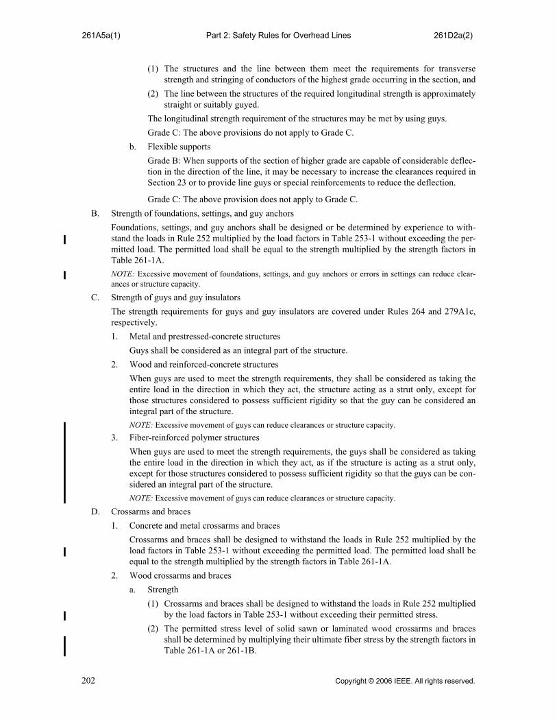
Part 2: Safety Rules for Overhead Lines261A5a(1) 261D2a(2)
(1) The structures and the line between them meet the requirements for transversestrength and stringing of conductors of the highest grade occurring in the section, and
(2) The line between the structures of the required longitudinal strength is approximatelystraight or suitably guyed.
The longitudinal strength requirement of the structures may be met by using guys.
Grade C: The above provisions do not apply to Grade C.
b. Flexible supports
Grade B: When supports of the section of higher grade are capable of considerable deflec-tion in the direction of the line, it may be necessary to increase the clearances required inSection 23 or to provide line guys or special reinforcements to reduce the deflection.
Grade C: The above provision does not apply to Grade C.
B. Strength of foundations, settings, and guy anchors
Foundations, settings, and guy anchors shall be designed or be determined by experience to with-stand the loads in Rule 252 multiplied by the load factors in Table 253-1 without exceeding the per-mitted load. The permitted load shall be equal to the strength multiplied by the strength factors inTable 261-1A.
NOTE: Excessive movement of foundations, settings, and guy anchors or errors in settings can reduce clear-ances or structure capacity.
C. Strength of guys and guy insulators
The strength requirements for guys and guy insulators are covered under Rules 264 and 279A1c,respectively.
1. Metal and prestressed-concrete structures
Guys shall be considered as an integral part of the structure.
2. Wood and reinforced-concrete structures
When guys are used to meet the strength requirements, they shall be considered as taking theentire load in the direction in which they act, the structure acting as a strut only, except forthose structures considered to possess sufficient rigidity so that the guy can be considered anintegral part of the structure.
NOTE: Excessive movement of guys can reduce clearances or structure capacity.
3. Fiber-reinforced polymer structures
When guys are used to meet the strength requirements, the guys shall be considered as takingthe entire load in the direction in which they act, as if the structure is acting as a strut only,except for those structures considered to possess sufficient rigidity so that the guys can be con-sidered an integral part of the structure.
NOTE: Excessive movement of guys can reduce clearances or structure capacity.
D. Crossarms and braces
1. Concrete and metal crossarms and braces
Crossarms and braces shall be designed to withstand the loads in Rule 252 multiplied by theload factors in Table 253-1 without exceeding the permitted load. The permitted load shall beequal to the strength multiplied by the strength factors in Table 261-1A.
2. Wood crossarms and braces
a. Strength
(1) Crossarms and braces shall be designed to withstand the loads in Rule 252 multipliedby the load factors in Table 253-1 without exceeding their permitted stress.
(2) The permitted stress level of solid sawn or laminated wood crossarms and bracesshall be determined by multiplying their ultimate fiber stress by the strength factors inTable 261-1A or 261-1B.
202 Copyright © 2006 IEEE. All rights reserved.

Part 2: Safety Rules for Overhead Lines261D2b 261E
b. Material and size
Wood crossarms and braces of select Southern pine or Douglas fir shall have a crosssection of not less than those in Table 261-2. Crossarms of other species may be usedprovided they have equal strength.
3. Fiber-reinforced polymer crossarms and braces
Crossarms and braces shall be designed to withstand the loads in Rule 252 multiplied by theload factors in Table 253-1 without exceeding the permitted load. The permitted load shall bethe 5th percentile strength (i.e., “5% lower exclusion limit”) or less, multiplied by the strengthfactors in Table 261-1A.
4. Crossarms and braces of other materials
Crossarms and braces should meet the strength requirements of Rule 261D2.
5. Additional requirements
a. Longitudinal strength
(1) General
(a) Crossarms shall be designed to withstand a load of 3.1 kN (700 lb) applied at theouter conductor attachment point without exceeding the permitted stress level forwood crossarms or the permitted load for crossarms of other materials, asapplicable.
(b) At each end of a transversely weak section, as described in Rule 261A4, the lon-gitudinal load shall be applied in the direction of the weak section.
(2) Methods of meeting Rule 261D2a(1)
Grade B: Where conductor tensions are limited to a maximum of 9.0 kN (2000 lb) perconductor, double wood crossarms having cross sections in Table 261-2 and properlyassembled will comply with the longitudinal strength requirements in Rule261D2a(1).
Grade C: This requirement is not applicable.
(3) Location
At crossings, crossarms should be mounted on the face of a pole away from the cross-ing, unless special bracing or double crossarms are used.
b. Bracing
Crossarms shall be supported by bracing, if necessary, to support expected loads,including line personnel working on them. Crossarm braces used only to sustainunbalanced vertical loads need only to be designed for these unbalanced vertical loads.
c. Double crossarms, brackets, or equivalent support assembly
Grade B: Where pin-type construction is used, double wood crossarms, each crossarmhaving the strength required by Rule 261D2a, or a support assembly equivalent in strengthto double wood crossarms shall be used at each crossing structure, at ends of joint use orconflict sections, at deadends, and at corners where the angle of departure from a straightline exceeds 20 degrees. Under similar conditions, where a bracket supports a conductoroperated at more than 750 V to ground and there is no crossarm below, double brackets ora support assembly equivalent in strength to double wood crossarms shall be used.
EXCEPTION: The above does not apply where communication cables or conductors cross belowsupply conductors and either are attached to the same pole, or where supply conductors are continu-ous and of uniform tension in the crossing span and each adjacent span. This exception does notapply to railroad crossings and limited access highways except by mutual agreement.
Grade C: The above requirement is not applicable.
E. Insulators
The strength requirements for insulators are covered under Rules 277 and 279.
Copyright © 2006 IEEE. All rights reserved. 203

Part 2: Safety Rules for Overhead Lines261F 261H1
F. Strength of pin-type or similar construction and conductor fastenings
1. Longitudinal strength
a. General
Pin-type or similar construction and ties or other conductor fastenings shall be designed towithstand the applicable longitudinal loads in Rule 252, multiplied by the load factors forlongitudinal loads in Table 253-1, or 3.1 kN (700 lb) applied at the pin, whichever isgreater.
b. Method of meeting Rule 261F1a
Grade B: Where conductor tensions are limited to 9.0 kN (2000 lb) and such conductorsare supported on pin insulators, double wood pins and ties or their equivalent will be con-sidered to meet the requirements of Rule 261F1a.
Grade C: No requirement.
c. At deadends and at ends of higher grade construction in line of lower grade
Grade B: Pins and ties or other conductor fastenings connected to the structure at adeadend or at each end of the higher grade section shall be designed to withstand anunbalanced pull due to the conductor load in Rule 251 multiplied by the load factors inRule 253-1.
Grade C: This requirement is not applicable except for deadends.
d. At ends of transverse sections described in Rule 261A4
Grade B: Pins and ties or other conductor fastenings connected to the structure at ends ofthe transverse section as described in Rule 261A4 shall be designed to withstand theunbalanced pull in the direction of that transverse section under the load in Rule 252 mul-tiplied by the load factors in Rule 253-1.
Grade C: No requirement.
2. Double pins and conductor fastenings
Grade B: Double pins and conductor fastenings shall be used where double crossarms or brack-ets are required by Rule 261D4d.
EXCEPTION: The above does not apply where communication cables or conductors cross below supplyconductors and either are attached to the same pole, or where supply conductors are continuous and ofuniform tension in a crossing span and each adjacent span. This exception does not apply in the case ofrailroad crossings and limited access highway crossings except by mutual agreement.
Grade C: No requirement.
3. Single supports used in lieu of double wood pins
A single conductor support and its conductor fastening, when used in lieu of double wood pins,shall develop strength equivalent to double wood pins and their conductor fastenings as speci-fied in Rule 261F1a.
G. Armless construction
1. General
Open conductor armless construction is a type of open conductor supply line construction inwhich conductors are individually supported at the structure without the use of crossarms.
2. Insulating material
Strength of insulating material shall meet the requirements of Section 27.
3. Other components
Strengths of other components shall meet the requirements of Rules 260 and 261.
H. Open supply conductors and overhead shield wires
1. Tensions
204 Copyright © 2006 IEEE. All rights reserved.

Part 2: Safety Rules for Overhead Lines261H1a 261K2
a. The supply conductor and overhead shield wire tensions shall be not more than 60% oftheir rated breaking strength for the load of Rule 250B in Rule 251 multiplied by a loadfactor of 1.0.
b. The tension at 15 °C (60 °F), without external load, shall not exceed the following per-centages of their rated breaking strength:
Initial unloaded tension 35%
Final unloaded tension 25%
EXCEPTION: In the case of conductors with a generally triangular cross section, such as cablescomposed of three wires, the final unloaded tension at 15 °C (60 °F) shall not exceed 30% of therated breaking strength of the conductor.
NOTE: The above limitations may not protect the conductor or facilities from damage due to aeolianvibration.
2. Splices, taps, dead-end fittings, and associated attachment hardware
a. Splices should be avoided in crossings and adjacent spans. If it is impractical to avoidsuch splices, they shall have sufficient strength to withstand the maximum tension result-ing from the loads of Rule 250B in Rule 251 multiplied by a load factor of 1.65. If Rules250C and 250D are applicable, splices shall not be stressed beyond 80% of their ratedbreaking strength under the loads of Rules 250C and 250D in Rule 251 multiplied by aload factor of 1.0.
b. Taps should be avoided in crossing spans but, if required, shall be of a type that will notimpair the strength of the conductors to which they are attached.
c. Dead-end fittings, including the associated attachment hardware, shall have sufficientstrength to withstand the maximum tension resulting from the loads of Rule 250B in Rule251 multiplied by a load factor of 1.65. If Rules 250C and 250D are applicable, deadendfittings shall not be stressed beyond 80% of their rated breaking strength under the loadsof Rules 250C and 250D in Rule 251 multiplied by a load factor of 1.0.
3. Trolley-contact conductors
In order to provide for wear, no trolley-contact conductor shall be installed of less size thanAWG No. 0, if of copper, or AWG No. 4, if of silicon bronze.
I. Supply cable messengers
Messengers shall be stranded and shall not be stressed beyond 60% of their rated breaking strengthunder the loads of Rule 250B in Rule 251 multiplied by a load factor of 1.0. If Rules 250C and 250Dare applicable, messengers shall not be stressed beyond 80% of their rated breaking strength underthe loads of Rules 250C and 250D in Rule 251 multiplied by a load factor of 1.0.
NOTE: There are no strength requirements for cables supported by messengers.
J. Open-wire communication conductors
Open-wire communication conductors in Grade B or C construction shall have the tensions in Rule261H1 for supply conductors of the same grade.
EXCEPTION: Where supply conductors are trolley-contact conductors of 0 to 750 V to ground, WG No. 12 Stlmay be used for communication conductors for spans of 0 to 30 m (0 to 100 ft), and Stl WG No. 9 may be usedfor spans of 38 to 45 m (125 to 150 ft).
K. Communication cables
1. Communication cables
There are no strength requirements for communication cables supported by messengers. SeeRule 261K2 for the strength requirements for messengers supporting communication cables.
2. Messenger
The messenger shall not be stressed beyond 60% of its rated breaking strength under the loadsof Rule 250B in Rule 251 multiplied by a load factor of 1.0. If Rules 250C and 250D are
Copyright © 2006 IEEE. All rights reserved. 205

Part 2: Safety Rules for Overhead Lines261L 261N
applicable, messengers shall not be stressed beyond 80% of their rated breaking strength underthe loads of Rules 250C and 250D in Rule 251 multiplied by a load factor of 1.0.
L. Paired communication conductors
1. Paired conductors supported on messenger
a. Use of messenger
A messenger may be used for supporting paired conductors in any location, but is requiredfor paired conductors crossing over trolley-contact conductors of more than 7.5 kV toground.
b. Tension of messenger
Messenger used for supporting paired conductors required to meet Grade B constructionbecause of crossing over trolley-contact conductors shall meet the tension requirementsfor Grade B.
c. Size and sag of conductors
There are no requirements for paired conductors when supported on messenger.
2. Paired conductors not supported on messenger
a. Above supply lines
Grade B: Tensions shall not exceed those in Rule 261H1 for supply conductors of similargrade.
Grade C: Sizes and tensions
Spans 0 to 30 m (0 to 100 ft)—No requirements.
Each conductor shall have a rated breaking strength of not less than 0.75 kN (170 lb).
Spans 30 to 45 m (100 to 150 ft)— Tensions shall not exceed those required for Grade Bcommunication conductors.
Spans exceeding 45 m (150 ft)—Tensions shall not exceed those required for Grade Csupply conductors. (See Rule 261H1.)
b. Above trolley-contact conductors
Grade B: Sizes and tensions
Spans 0 to 30 m (0 to 100 ft)—No size requirements. Tensions shall not exceed those ofRule 261H1.
Spans exceeding 30 m (100 ft)—Each conductor shall have a rated breaking strength ofnot less than 0.75 kN (170 lb). Tensions shall not exceed those of Rule 261H1.
Grade C: Sizes and tensions
Spans 0 to 30 m (0 to 100 ft)—No requirements.
Spans exceeding 30 m (100 ft)—No tension requirements.
Each conductor shall have a rated breaking strength of not less than 0.75 kN (170 lb).
M. Support and attachment hardware
The strength required for all support and attachment hardware not covered by Rule 261F or 261H2shall be not less than the load times the appropriate load factor given in Section 25 and the load fac-tor shall not be less than 1.0. For appropriate strength factors, see Rule 260B.
N. Climbing and working steps and their attachments to the structure
The strength required for all climbing devices (includes steps, ladders, platforms and their attach-ments) shall be capable of supporting 2.0 times the maximum intended load without permanentdeformation. Unless otherwise quantified by the owner, the maximum intended load shall beassumed to be 300 lb, which includes the weight of the lineman, harness, tools, and equipment beingsupported by the lineman.
NOTE: See IEEE Std 1307™-2004 [B52].
206 Copyright © 2006 IEEE. All rights reserved.
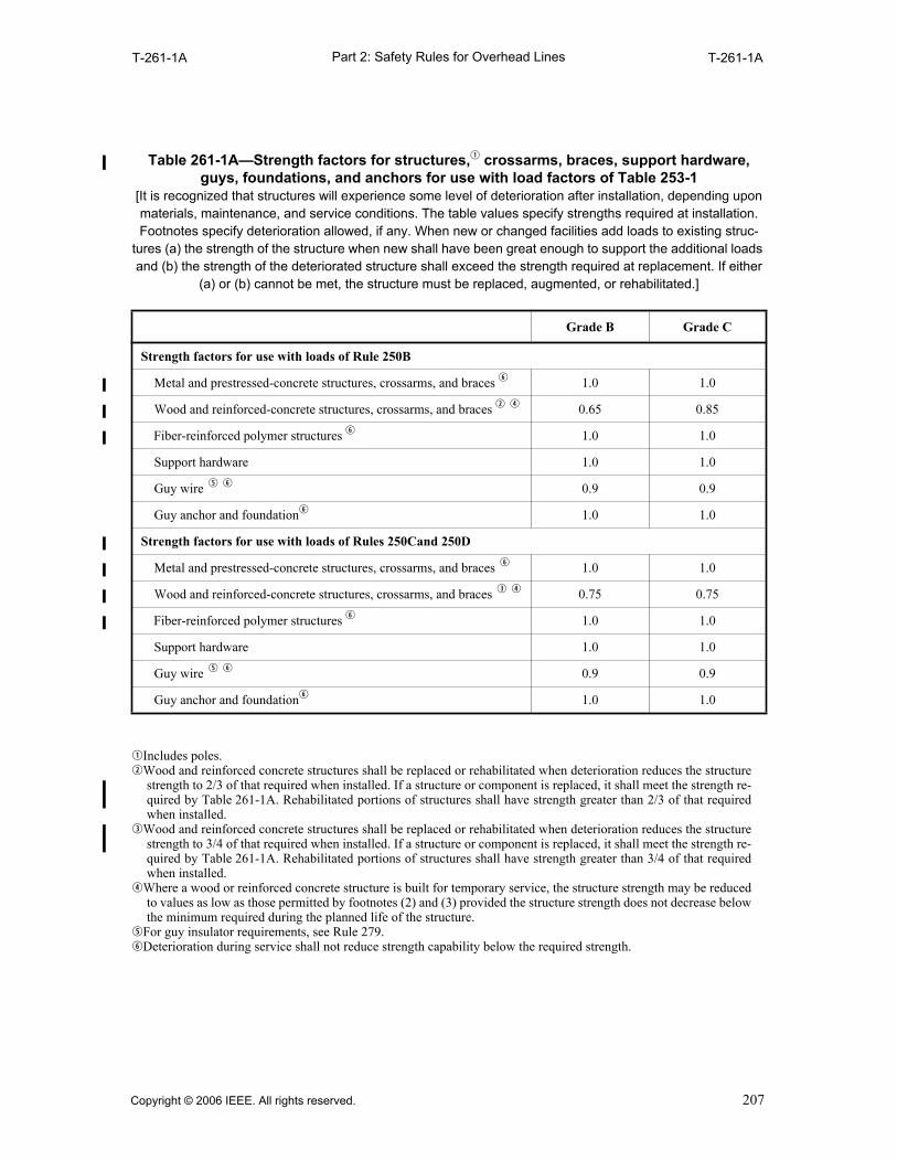
Part 2: Safety Rules for Overhead LinesT-261-1A T-261-1A
qIncludes poles.wWood and reinforced concrete structures shall be replaced or rehabilitated when deterioration reduces the structure
strength to 2/3 of that required when installed. If a structure or component is replaced, it shall meet the strength re-quired by Table 261-1A. Rehabilitated portions of structures shall have strength greater than 2/3 of that requiredwhen installed.
eWood and reinforced concrete structures shall be replaced or rehabilitated when deterioration reduces the structurestrength to 3/4 of that required when installed. If a structure or component is replaced, it shall meet the strength re-quired by Table 261-1A. Rehabilitated portions of structures shall have strength greater than 3/4 of that requiredwhen installed.
rWhere a wood or reinforced concrete structure is built for temporary service, the structure strength may be reducedto values as low as those permitted by footnotes (2) and (3) provided the structure strength does not decrease belowthe minimum required during the planned life of the structure.
tFor guy insulator requirements, see Rule 279.yDeterioration during service shall not reduce strength capability below the required strength.
Table 261-1A—Strength factors for structures,q crossarms, braces, support hardware, guys, foundations, and anchors for use with load factors of Table 253-1
[It is recognized that structures will experience some level of deterioration after installation, depending upon materials, maintenance, and service conditions. The table values specify strengths required at installation. Footnotes specify deterioration allowed, if any. When new or changed facilities add loads to existing struc-
tures (a) the strength of the structure when new shall have been great enough to support the additional loads and (b) the strength of the deteriorated structure shall exceed the strength required at replacement. If either
(a) or (b) cannot be met, the structure must be replaced, augmented, or rehabilitated.]
Grade B Grade C
Strength factors for use with loads of Rule 250B
Metal and prestressed-concrete structures, crossarms, and braces y 1.0 1.0
Wood and reinforced-concrete structures, crossarms, and braces w r 0.65 0.85
Fiber-reinforced polymer structures y 1.0 1.0
Support hardware 1.0 1.0
Guy wire t y 0.9 0.9
Guy anchor and foundationy 1.0 1.0
Strength factors for use with loads of Rules 250Cand 250D
Metal and prestressed-concrete structures, crossarms, and braces y 1.0 1.0
Wood and reinforced-concrete structures, crossarms, and braces e r 0.75 0.75
Fiber-reinforced polymer structures y 1.0 1.0
Support hardware 1.0 1.0
Guy wire t y 0.9 0.9
Guy anchor and foundationy 1.0 1.0
Copyright © 2006 IEEE. All rights reserved. 207
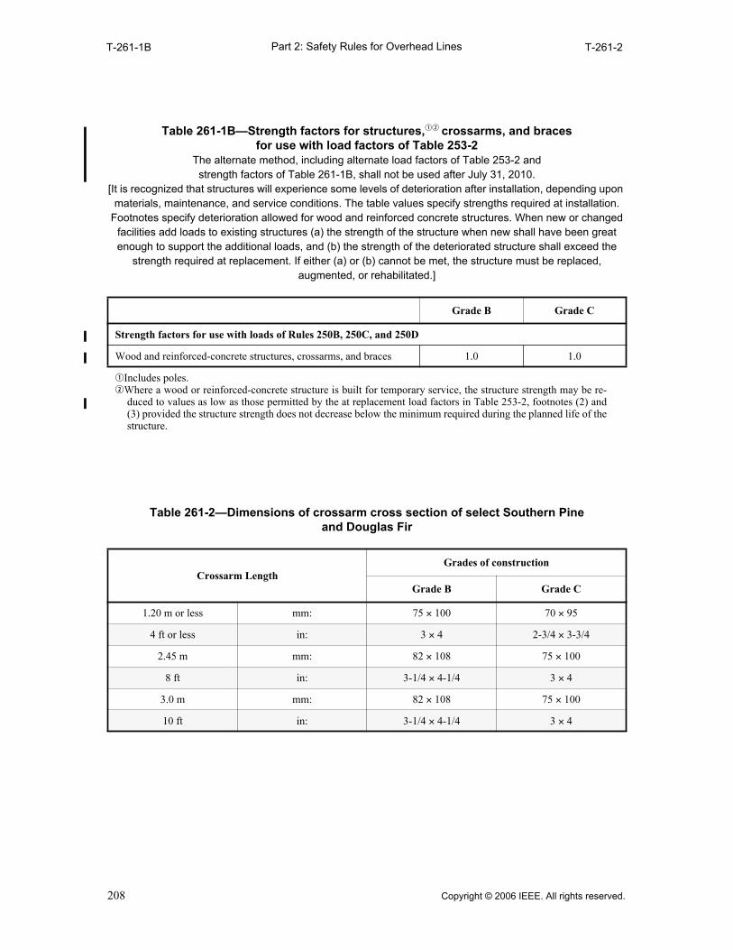
Part 2: Safety Rules for Overhead LinesT-261-1B T-261-2
Table 261-1B—Strength factors for structures,qw crossarms, and braces for use with load factors of Table 253-2
The alternate method, including alternate load factors of Table 253-2 and strength factors of Table 261-1B, shall not be used after July 31, 2010.
[It is recognized that structures will experience some levels of deterioration after installation, depending upon materials, maintenance, and service conditions. The table values specify strengths required at installation.
Footnotes specify deterioration allowed for wood and reinforced concrete structures. When new or changed facilities add loads to existing structures (a) the strength of the structure when new shall have been great enough to support the additional loads, and (b) the strength of the deteriorated structure shall exceed the
strength required at replacement. If either (a) or (b) cannot be met, the structure must be replaced, augmented, or rehabilitated.]
Grade B Grade C
Strength factors for use with loads of Rules 250B, 250C, and 250D
Wood and reinforced-concrete structures, crossarms, and braces 1.0 1.0
qIncludes poles.wWhere a wood or reinforced-concrete structure is built for temporary service, the structure strength may be re-
duced to values as low as those permitted by the at replacement load factors in Table 253-2, footnotes (2) and(3) provided the structure strength does not decrease below the minimum required during the planned life of thestructure.
Table 261-2—Dimensions of crossarm cross section of select Southern Pine and Douglas Fir
Crossarm LengthGrades of construction
Grade B Grade C
1.20 m or less mm: 75 × 100 70 × 95
4 ft or less in: 3 × 4 2-3/4 × 3-3/4
2.45 m mm: 82 × 108 75 × 100
8 ft in: 3-1/4 × 4-1/4 3 × 4
3.0 m mm: 82 × 108 75 × 100
10 ft in: 3-1/4 × 4-1/4 3 × 4
208 Copyright © 2006 IEEE. All rights reserved.

Part 2: Safety Rules for Overhead Lines262 263E3b
262. Number 262 not used in this edition.
263. Grade N construction
The strength of Grade N construction need not be equal to or greater than Grade C.
A. Poles
Poles used for lines for which neither Grade B nor C is required shall be of initial size or guyed orbraced to withstand expected loads, including line personnel working on them.
B. Guys
The general requirements for guys are covered in Rules 264 and 279A.
C. Crossarm strength
Crossarms shall be securely supported by bracing, if necessary, to withstand expected loads, includ-ing line personnel working on them.
NOTE: Double crossarms are generally used at crossings, unbalanced corners, and dead ends, in order to permitconductor fastenings at two insulators to limit the opportunity for slipping, although single crossarms mightprovide sufficient strength. To secure extra strength, double crossarms are frequently used, and crossarm guysare sometimes used.
D. Supply line conductors
1. Size
Supply-line conductors shall be not smaller than the sizes listed in Table 263-1.
RECOMMENDATION: It is recommended that these sizes for copper and steel not be used in spanslonger than 45 m (150 ft) for the heavy-loading district, and 53 m (175 ft) for the medium- and light-loading districts.
E. Service drops
1. Size of open-wire service drops
a. Not over 750 V.
Service drops shall be as required by (1) or (2):
(1) Spans not exceeding 45 m (150 ft)
Sizes shall be not smaller than those in Table 263-2.
(2) Spans exceeding 45 m (150 ft)
Sizes shall be not smaller than 8 AWG.
b. Exceeding 750 V
Sizes of service drops of more than 750 V shall be not less than required for supply lineconductors of the same voltage.
2. Tension of open-wire service drops
The tension of the service drop conductors shall not exceed the strength of the conductorattachment or its support under the expected loads.
3. Cabled service drops
Service conductors may be grouped together in a cable, provided the following requirementsare met:
a. Size
The size of each conductor shall be not less than required for drops of separate conductors(Rule 263E1).
b. Tension of cabled service drops
The tension of the service drop conductors shall not exceed the strength of the conductorattachment or its support under the expected loads.
Copyright © 2006 IEEE. All rights reserved. 209
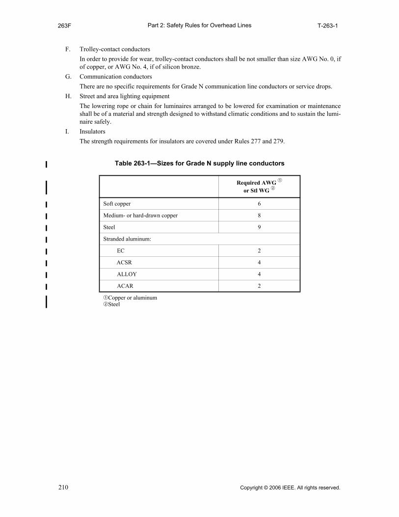
Part 2: Safety Rules for Overhead Lines263F T-263-1
F. Trolley-contact conductors
In order to provide for wear, trolley-contact conductors shall be not smaller than size AWG No. 0, ifof copper, or AWG No. 4, if of silicon bronze.
G. Communication conductors
There are no specific requirements for Grade N communication line conductors or service drops.
H. Street and area lighting equipment
The lowering rope or chain for luminaires arranged to be lowered for examination or maintenanceshall be of a material and strength designed to withstand climatic conditions and to sustain the lumi-naire safely.
I. Insulators
The strength requirements for insulators are covered under Rules 277 and 279.
Table 263-1—Sizes for Grade N supply line conductors
Required AWG q or Stl WG w
Soft copper 6
Medium- or hard-drawn copper 8
Steel 9
Stranded aluminum:
EC 2
ACSR 4
ALLOY 4
ACAR 2
qCopper or aluminumwSteel
210 Copyright © 2006 IEEE. All rights reserved.

Part 2: Safety Rules for Overhead LinesT-263-2 264C
qInstallation of service drops of not more than 750 V above supply lines of more than 750 V should be avoided wherepractical.
wACSR or high-strength aluminum alloy conductor size shall be not less than No. 6.
264. Guying and bracing
A. Where used
When the loads are greater than can be supported by the structure alone, additional strength shall beprovided by the use of guys, braces, or other suitable construction. Such measures shall also be usedwhere necessary to limit the increase of sags in adjacent spans and provide sufficient strength forthose supports on which the loads are sufficiently unbalanced, for example, at corners, angles, deadends, large differences in span lengths, and changes of grade of construction.
B. Strength
Guys shall be designed to withstand the loads in Rule 252 multiplied by the load factors inTable 253-1 without exceeding the permitted load. The permitted load shall be equal to the strengthmultiplied by the strength factors in Table 261-1A. For guy wires conforming to ASTM Standards, theminimum breaking strength value therein defined shall be the rated breaking strength required in thisCode.
NOTE: For protection and marking of guys, see Rule 217C.
C. Point of attachment
The guy or brace should be attached to the structure as near as is practical to the center of the con-ductor load to be sustained. However, on lines exceeding 8.7 kV, the location of the guy or bracemay be adjusted to minimize the reduction of the insulation offered by nonmetallic support arms andsupporting structures.
Table 263-2—Sizes of service drops of 750 V or less (Voltages of trolley-contact conductors are voltage to ground.
AWG used for aluminum and copper wires; Stl WG used for steel wire.)
Copper wire
Situation Soft-drawn Medium- orhard-drawn Steel wire EC aluminum
wire w
Alone 10 12 12 4
Concerned with communication conductor
10 12 12 4
Over supply conductors of
0 to 750 V 10 12 12 4
750 V to 8.7 kV q 8 10 12 4
Exceeding 8.7 kV q 6 8 9 4
Over trolley-contact conductors
0 to 750 V ac or dc 8 10 12 4
Exceeding 750 V ac or dc 6 8 9 4
Copyright © 2006 IEEE. All rights reserved. 211
Part 2: Safety Rules for Overhead Lines264D 264F2
D. Guy fastenings
Guys having a rated breaking strength of 9.0 kN (2000 lb) or more and that are subject to smallradius bends should be stranded and should be protected by suitable guy thimbles or theirequivalent. Any guy having a design loading of 44.5 kN (10 000 lb) or more wrapped around cedaror similar softwood poles should be protected by the use of suitable guy shims.
Where there is a tendency for the guy to slip off the shim, guy hooks or other suitable means oflimiting the likelihood of this action should be used. Shims are not necessary in the case ofsupplementary guys, such as storm guys.
E. Electrolysis
Where anchors and rods are subject to electrolysis, suitable measures should be taken to minimizecorrosion from this source.
F. Anchor rods
1. Anchor rods should be installed so as to be in line with the pull of the attached guy when underload.
EXCEPTION: This is not required for anchor rods installed in rock or concrete.
2. The anchor and rod assembly shall have an ultimate strength not less than that required of theguy(s) by Rule 264B.
212 Copyright © 2006 IEEE. All rights reserved.

Part 2: Safety Rules for Overhead LInes270 273
Section 27.Line insulation
270. Application of rule
These requirements apply only to open-conductor supply lines.
NOTE 1: See Rule 243C5.
NOTE 2: See Rule 242E for insulation requirements for neutral conductors.
271. Material and marking
Insulators for operation of supply circuits shall be made of wet-process porcelain or other materialthat will provide equivalent or better electrical and mechanical performance. Insulators for use at orabove 2.3 kV between conductors shall be marked by the maker with its name or trademark and anidentification mark or markings that will permit determination of the electrical and mechanical prop-erties. The marking shall be applied so as not to reduce the electrical or mechanical strength of theinsulator.
NOTE: The identifying marking can be either a catalog number, trade number, or other means so that propertiesof the unit can be determined either through catalogs or other literature.
272. Ratio of flashover to puncture voltage
Insulators shall be designed so that the ratio of their rated low-frequency dry-flashover voltage tolow-frequency puncture voltage is in conformance with applicable American National Standards.When a standard does not exist, this ratio shall not exceed 75%.
The applicable American National Standards are as follows:
ANSI C29.1-1988
ANSI C29.2-1992
ANSI C29.3-1986
ANSI C29.4-1989
ANSI C29.5-1984
ANSI C29.6-1996
ANSI C29.7-1996
EXCEPTION: Insulators specifically designed for use in areas of high atmospheric contamination may have arated low-frequency dry-flashover voltage not more than 80% of their low-frequency puncture voltage.
273. Insulation level
The rated dry flashover voltage of the insulator or insulators, when tested in accordance withANSI C29.1-1988, shall be not less than that shown in Table 273-1, unless based on a qualifiedengineering study. Higher insulation levels than those shown in Table 273-1, or other effectivemeans, shall be used where severe lightning, high atmospheric contamination, or other unfavorableconditions exist. Insulation levels for system voltages in excess of those shown shall be based on aqualified engineering study.
Copyright © 2006 IEEE. All rights reserved. 213
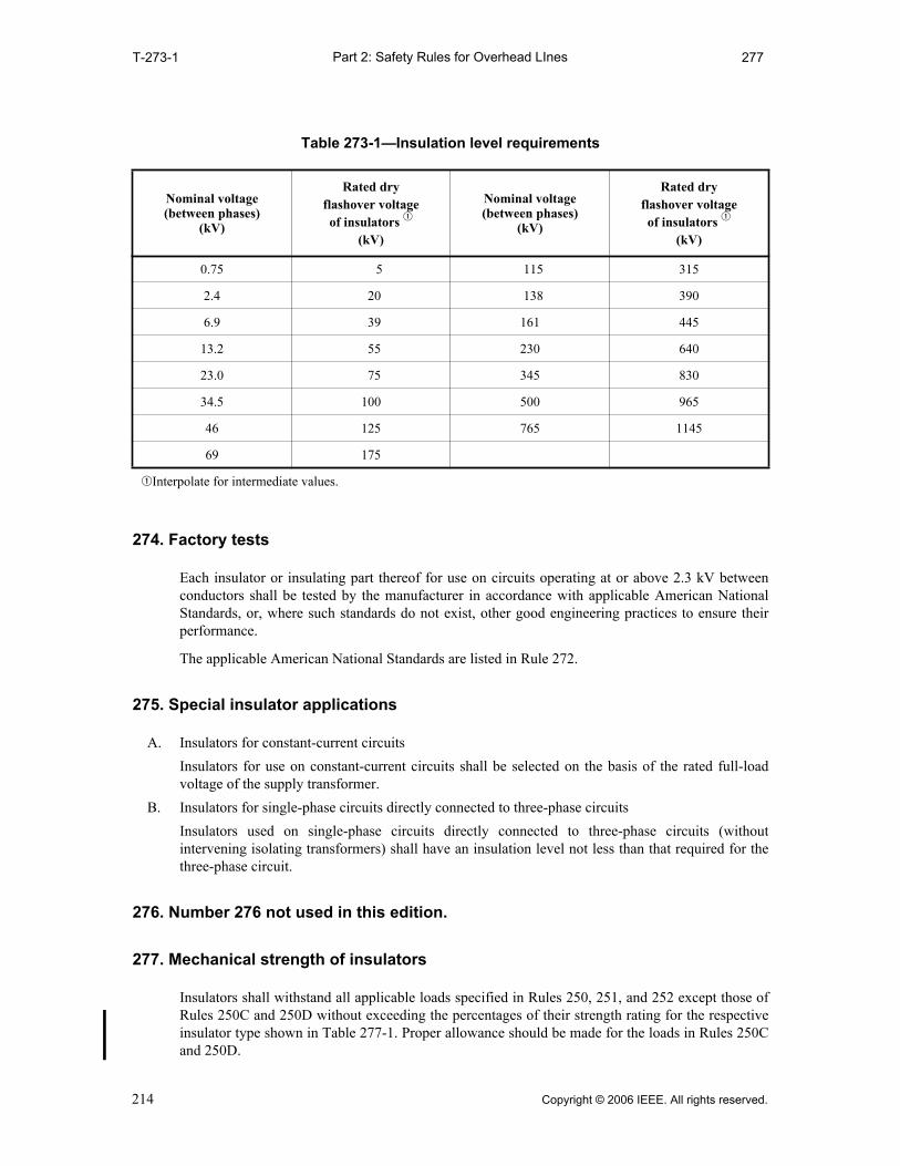
Part 2: Safety Rules for Overhead LInesT-273-1 277
274. Factory tests
Each insulator or insulating part thereof for use on circuits operating at or above 2.3 kV betweenconductors shall be tested by the manufacturer in accordance with applicable American NationalStandards, or, where such standards do not exist, other good engineering practices to ensure theirperformance.
The applicable American National Standards are listed in Rule 272.
275. Special insulator applications
A. Insulators for constant-current circuits
Insulators for use on constant-current circuits shall be selected on the basis of the rated full-loadvoltage of the supply transformer.
B. Insulators for single-phase circuits directly connected to three-phase circuits
Insulators used on single-phase circuits directly connected to three-phase circuits (withoutintervening isolating transformers) shall have an insulation level not less than that required for thethree-phase circuit.
276. Number 276 not used in this edition.
277. Mechanical strength of insulators
Insulators shall withstand all applicable loads specified in Rules 250, 251, and 252 except those ofRules 250C and 250D without exceeding the percentages of their strength rating for the respectiveinsulator type shown in Table 277-1. Proper allowance should be made for the loads in Rules 250Cand 250D.
Table 273-1—Insulation level requirements
Nominal voltage(between phases)
(kV)
Rated dryflashover voltageof insulators q
(kV)
Nominal voltage(between phases)
(kV)
Rated dryflashover voltageof insulators q
(kV)
0.75 5 115 315
2.4 20 138 390
6.9 39 161 445
13.2 55 230 640
23.0 75 345 830
34.5 100 500 965
46 125 765 1145
69 175
qInterpolate for intermediate values.
214 Copyright © 2006 IEEE. All rights reserved.
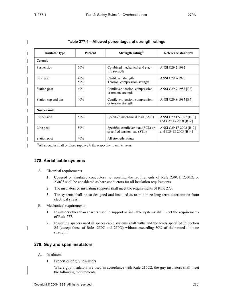
Part 2: Safety Rules for Overhead LInesT-277-1 279A1
278. Aerial cable systems
A. Electrical requirements
1. Covered or insulated conductors not meeting the requirements of Rule 230C1, 230C2, or230C3 shall be considered as bare conductors for all insulation requirements.
2. The insulators or insulating supports shall meet the requirements of Rule 273.
3. The systems shall be so designed and installed as to minimize long-term deterioration fromelectrical stress.
B. Mechanical requirements
1. Insulators other than spacers used to support aerial cable systems shall meet the requirementsof Rule 277.
2. Insulating spacers used in spacer cable systems shall withstand the loads specified in Section25 (except those of Rules 250C and 250D) without exceeding 50% of their rated ultimatestrength.
279. Guy and span insulators
A. Insulators
1. Properties of guy insulators
Where guy insulators are used in accordance with Rule 215C2, the guy insulators shall meetthe following requirements:
Table 277-1—Allowed percentages of strength ratings
Insulator type Percent Strength ratingq Reference standard
Ceramic
Suspension 50% Combined mechanical and elec-tric strength
ANSI C29.2-1992
Line post 40%50%
Cantilever strengthTension, compression strength
ANSI C29.7-1996
Station post 40% Cantilever, tension, compression or torsion strength
ANSI C29.9-1983 [B8]
Station cap and pin 40% Cantilever, tension, compression or torsion strength
ANSI C29.8-1985 [B7]
Nonceramic
Suspension 50% Specified mechanical load (SML) ANSI C29.12-1997 [B11] and C29.13-2000 [B12]
Line post 50% Specified cantilever load (SCL) or specified tension load (STL)
ANSI C29.17-2002 [B13] and C29.18-2003 [B14]
Station post 40% All strength ratings
qAll strengths shall be those supplied b the respective manufacturers.
Copyright © 2006 IEEE. All rights reserved. 215

Part 2: Safety Rules for Overhead LInes279A1a 279B3
a. Material
Insulators shall be made of wet-process porcelain, wood, fiberglass-reinforced plastic, orother material of suitable mechanical and electrical properties.
b. Electrical strength
The guy insulator shall have a rated dry flashover voltage at least double, and a rated wetflashover voltage at least as high as, the nominal line voltage between conductors of theguyed circuit. A guy insulator may consist of one or more units.
c. Mechanical strength
The rated ultimate strength of the guy insulator shall be at least equal to the requiredstrength of the guy in which it is installed.
2. Galvanic corrosion and BIL insulation
a. Limitation of galvanic corrosion
An insulator in the guy strand used exclusively to limit galvanic corrosion of metal inground rods, anchors, anchor rods, or pipe in an effectively grounded system shall not beclassified as a guy insulator and shall not reduce the mechanical strength of the guy.
NOTE: See Rule 215C7.
b. BIL insulation
An insulator in the guy strand used exclusively to meet BIL requirements for the structurein an effectively grounded system, as shown in Figure 279-1, shall not be classified as aguy insulator, provided mechanical strength of the insulator meets Rule 279A1c and eitherof the following provisions is met:
(1) The guy is otherwise insulated to meet the requirements of Rule 279A1
(2) Anchor guys are grounded below the insulator in accordance with Rules 215C5 and92C2
B. Properties of span-wire insulators
Where span-wire insulators are used in accordance with Rule 215C, the span-wire insulators shallmeet the following requirements:
1. Material
Insulators shall be made of wet-process porcelain, wood, fiberglass, or other material of suit-able mechanical and electrical properties.
2. Insulation level
The insulation level of span-wire insulators shall meet the requirements of Rule 274.
A hanger insulator, where used to provide single insulation as permitted by Rule 279B2, shallmeet the requirements of Rule 274.
3. Mechanical strength
The rated ultimate strength of the span-wire insulator shall be at least equal to the requiredstrength of the span wire in which it is located.
216 Copyright © 2006 IEEE. All rights reserved.
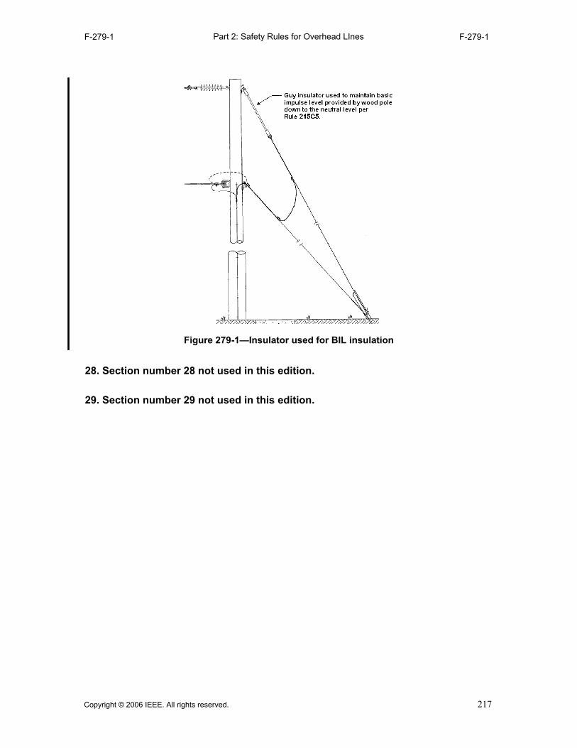
Part 2: Safety Rules for Overhead LInesF-279-1 F-279-1
28. Section number 28 not used in this edition.
29. Section number 29 not used in this edition.
Figure 279-1—Insulator used for BIL insulation
Copyright © 2006 IEEE. All rights reserved. 217

Part 2: Safety Rules for Overhead LInes
218 Copyright © 2006 IEEE. All rights reserved.

Part 3: Safety Rules for Underground Lines300 302
Part 3.Safety Rules for the Installation and Maintenance of
Underground Electric Supply and Communication Lines
Section 30.Purpose, scope, and application of rules
300. Purpose
The purpose of Part 3 of this Code is the practical safeguarding of persons during the installation,operation, or maintenance of underground or buried supply and communication cables andassociated equipment.
301. Scope
Part 3 of this Code covers supply and communication cables and equipment in underground orburied systems. The rules cover the associated structural arrangements and the extension of suchsystems into buildings. It also covers the cables and equipment employed primarily for theutilization of electric power when such cables and equipment are used by the utility in the exerciseof its function as a utility. They do not cover installations in electric supply stations.
302. Application of rules
The general requirements for application of these rules are contained in Rule 13.
Copyright © 2006 IEEE. All rights reserved. 219

Part 3: Safety Rules for Underground Lines310 313B2
Section 31.General requirements applying to underground lines
310. Referenced sections
The Introduction (Section 1), Definitions (Section 2), List of referenced documents (Section 3), andGrounding methods (Section 9) of this Code shall apply to the requirements of Part 3.
311. Installation and maintenance
A. Persons responsible for underground facilities shall be able to indicate the location of their facilities.
B. Reasonable advance notice should be given to owners or operators of other proximate facilities thatmay be adversely affected by new construction or changes in existing facilities.
C. For emergency installations, supply and communication cables may be laid directly on grade if theyare guarded or otherwise located so that they do not unduly obstruct pedestrian or vehicular trafficand are appropriately marked. Supply cables operating above 600 V shall meet either Rule 230C or350B.
312. Accessibility
All parts that must be examined or adjusted during operation shall be arranged so as to be accessibleto authorized persons by the provision of adequate working spaces, working facilities, andclearances.
313. Inspection and tests of lines and equipment
A. When in service
1. Initial compliance with safety rules
Lines and equipment shall comply with these safety rules upon being placed in service.
2. Inspection
Accessible lines and equipment shall be inspected by the responsible party at such intervals asexperience has shown to be necessary.
3. Tests
When considered necessary, lines and equipment shall be subjected to practical tests todetermine required maintenance.
4. Record of defects
Any defects affecting compliance with this Code revealed by inspection, if not promptlycorrected, shall be recorded; such record shall be maintained until the defects are corrected.
5. Remedying defects
Lines and equipment with recorded defects that would endanger life or property shall bepromptly repaired, disconnected, or isolated.
B. When out of service
1. Lines infrequently used
Lines and equipment infrequently used shall be inspected or tested as necessary before beingplaced into service.
2. Lines temporarily out of service
Lines and equipment temporarily out of service shall be maintained in a safe condition.
220 Copyright © 2006 IEEE. All rights reserved.
Part 3: Safety Rules for Underground Lines313B3 315B
3. Lines permanently abandoned
Lines and equipment permanently abandoned shall be removed or maintained in a safecondition.
314. Grounding of circuits and equipment
A. Methods
The methods to be used for grounding of circuits and equipment are given in Section 9.
B. Conductive parts to be grounded
Cable sheaths and shields (except conductor shields), equipment frames and cases (including pad-mounted devices), and conductive lighting poles shall be effectively grounded. Conductive-materialducts and riser guards that enclose electric supply lines or are exposed to contact with open supplyconductors of greater than 300 V shall be effectively grounded.
EXCEPTION: This rule does not apply to parts that are 2.45 m (8 ft) or more above readily accessible surfacesor are otherwise isolated or guarded.
C. Circuits
1. Neutrals
Primary neutrals, secondary and service neutrals, and common neutrals shall be effectivelygrounded as specified in Rule 314A.
EXCEPTION: Circuits designed for ground-fault detection and impedance current-limiting devices.
2. Other conductors
Conductors, other than neutral conductors, that are intentionally grounded, shall be effectivelygrounded as specified in Rule 314A.
3. Surge arresters
Surge arresters shall be effectively grounded as specified in Rule 314A.
4. Use of earth as part of circuit
a. Supply circuits shall not be designed to use the earth normally as the sole conductor forany part of the circuit.
b. Monopolar operation of a bipolar HVDC system is permissible for emergencies and lim-ited periods for maintenance.
315. Communications protective requirements
A. Where required
Where communications apparatus is handled by other than qualified persons, it shall be protected byone or more of the means listed in Rule 315B if such apparatus is permanently connected to linessubject to any of the following:
1. Lightning
2. Contact with supply conductors with voltages exceeding 300 V
3. Transient rise in ground potential exceeding 300 V
4. Steady-state induced voltage of a level that may cause personal injury
NOTE: When communication cables will be in the vicinity of supply stations where large ground currentsmay flow, the effect of these currents on communication circuits should be evaluated.
B. Means of protection
Where communications apparatus is required to be protected under Rule 315A, protective meansadequate to withstand the voltage expected to be impressed shall be provided by insulation,
Copyright © 2006 IEEE. All rights reserved. 221

Part 3: Safety Rules for Underground Lines316 316
protected where necessary by surge arresters. Severe conditions may require the use of additionaldevices such as auxiliary arresters, drainage coils, neutralizing transformers, or isolating devices.
316. Induced voltage
Rules covering supply-line influence and communication-line susceptiveness have not been detailedin this Code. Cooperative procedures are recommended to minimize steady-state voltages inducedfrom proximate facilities. Therefore, reasonable advance notice should be given to owners oroperators of other known proximate facilities that may be adversely affected by new construction orchanges in existing facilities.
222 Copyright © 2006 IEEE. All rights reserved.

Part 3: Safety Rules for Underground Lines320 320A6
Section 32.Underground conduit systems
NOTE 1: While it is often the practice to use duct and conduit interchangeably, duct, as used herein, is a single enclosedraceway for conductors or cable; conduit is a structure containing one or more ducts; and conduit system is the combina-tion of conduit, conduits, manholes, handholes, and/or vaults joined to form an integrated whole.
NOTE 2: For cables installed in a single duct not part of a conduit system: see Rule 350G.
320. Location
A. Routing
1. General
a. Conduit systems should be subject to the least disturbance practical. Conduit systemsextending parallel to other subsurface structures should not be located directly over orunder other subsurface structures. If this is not practical, the rule on separation, as stated inRule 320B, should be followed.
b. Conduit alignment should be such that there are no protrusions that would be harmful tothe cable.
c. Where bends are required, the bending radius shall be sufficiently large to limit the likeli-hood of damage to cable being installed in the conduit.
2. Natural hazards
Routes through unstable soils such as mud, shifting soil, etc., or through highly corrosive soils,should be avoided. If construction is required in these soils, the conduit should be constructedin such a manner as to minimize movement or corrosion or both.
3. Highways and streets
Where conduit must be installed longitudinally under the roadway, it should be installed in theshoulder. If this is not practical, the conduit should be installed within the limits of one lane oftraffic.
4. Bridges and tunnels
The conduit system shall be located so as to limit the likelihood of damage by traffic. It shouldbe located to provide safe access for inspection or maintenance of both the structure and theconduit system.
5. Crossing railroad tracks
a. The top of the conduit system should be located not less than 900 mm (36 in) below thetop of the rails of a street railway or 1.27 m (50 in) below the top of the rails of a railroad.Where unusual conditions exist or where proposed construction would interfere withexisting installations, a greater depth than specified above may be required.
EXCEPTION: Where this is impractical, or for other reasons, this separation may be reduced byagreement between the parties concerned. In no case, however, shall the top of the conduit or anyconduit protection extend higher than the bottom of the ballast section that is subject to working orcleaning.
b. At crossings under railroads, manholes, handholes, and vaults should not, where practical,be located in the roadbed.
6. Submarine crossing
Submarine crossings should be routed, installed, or both so they will be protected from erosionby tidal action or currents. They should not be located where ships normally anchor.
Copyright © 2006 IEEE. All rights reserved. 223

Part 3: Safety Rules for Underground Lines320B 321B
B. Separation from other underground installations
1. General
The separation between a conduit system and other underground structures paralleling it shouldbe as large as necessary to permit maintenance of the system without damage to the parallelingstructures. A conduit that crosses over another subsurface structure shall have a separationsufficient to limit the likelihood of damage to either structure. These separations should bedetermined by the parties involved.
EXCEPTION: When conduit crosses a manhole, vault, or subway tunnel roof, it may be supporteddirectly on the roof with the concurrence of all parties involved.
2. Separations between supply and communication conduit systems
Conduit systems to be occupied by communication conductors shall be separated from conduitsystems to be used for supply systems by not less than
a. 75 mm (3 in) of concrete
b. 100 mm (4 in) of masonry
c. 300 mm (12 in) of well-tamped earth
EXCEPTION: Lesser separations may be used where the parties concur.
3. Sewers, sanitary and storm
a. If conditions require a conduit to be installed parallel to and directly over a sanitary orstorm sewer, it may be done provided both parties are in agreement as to the method.
b. Where a conduit run crosses a sewer, it shall be designed to have suitable support on eachside of the sewer to limit the likelihood of transferring any direct load onto the sewer.
4. Water lines
Conduit should be installed as far as is practical from a water main in order to protect it frombeing undermined if the main breaks. Conduit that crosses over a water main shall be designedto have suitable support on each side as required to limit the likelihood of transferring anydirect loads onto the main.
5. Gas and other lines that transport flammable material
Conduit should have sufficient separation from gas and other lines that transport flammablematerial to permit the use of pipe maintenance equipment. Conduit shall not enter the samemanhole, handhole, or vault with gas or other lines that transport flammable material.
6. Steam lines
Conduit should be installed so as to limit the likelihood of detrimental heat transfer between thesteam and conduit systems.
321. Excavation and backfill
A. Trench
The bottom of the trench should be undisturbed, tamped, or relatively smooth earth. Where theexcavation is in rock, the conduit should be laid on a protective layer of clean tamped backfill.
B. Quality of backfill
All backfill should be free of materials that may damage the conduit system.
RECOMMENDATION: Backfill within 150 mm (6 in) of the conduit should be free of solid material greaterthan 100 mm (4 in) in maximum dimension or with sharp edges likely to damage it. The balance of backfillshould be free of solid material greater than 200 mm (8 in) in maximum dimension. Backfill material should beadequately compacted.
224 Copyright © 2006 IEEE. All rights reserved.

Part 3: Safety Rules for Underground Lines322 323A
322. Ducts and joints
A. General
1. Duct material shall be corrosion-resistant and suitable for the intended environment.
2. Duct materials, the construction of the conduit, or both shall be designed so that a cable fault inone duct would not damage the conduit to such an extent that it would cause damage to cablesin adjacent ducts.
3. The conduit system shall be designed to withstand external forces to which it may be subjectedby the surface loadings set forth in Rule 323A, except that impact loading may be reduced onethird for each 300 mm (12 in) of cover so no impact loading need be considered when cover is900 mm (3 ft) or more.
4. The internal surface of the duct shall be free of sharp edges or burrs, which could damage sup-ply cable.
B. Installation
1. Restraint
Conduit, including terminations and bends, should be suitably restrained by backfill, concreteenvelope, anchors, or other means to maintain its design position under stress of installationprocedures, cable pulling operations, and other conditions such as settling and hydraulic orfrost uplift.
2. Joints
Ducts shall be joined in a manner so as to limit solid matter from entering the conduit line.Joints shall form a sufficiently continuous smooth interior surface between joining ductsections so that supply cable will not be damaged when pulled past the joint.
3. Externally coated pipe
When conditions are such that externally coated pipe is required, the coating shall be corrosionresistant and should be inspected, tested, or both, to see that the coating is continuous and intactprior to backfill. Precautions shall be taken to prevent damage to the coating when backfilling.
4. Building walls
Conduit installed through a building wall shall have internal and external seals intended to limitthe likelihood of the entrance of gas into the building. The use of seals may be supplemented bygas-venting devices in order to minimize building up of positive gas pressures in the conduit.
5. Bridges
a. Conduit installed in bridges shall include the capability to allow for expansion and con-traction of the bridge.
b. Conduits passing through a bridge abutment should be installed so as to avoid or resist anyshear due to soil settlement.
c. Conduit of conductive material installed on bridges shall be effectively grounded.
6. In vicinity of manholes
Conduit should be installed on compacted soil or otherwise supported when entering a manholeto limit the likelihood of detrimental shear stress on the conduit at the point of manholeentrance.
323. Manholes, handholes, and vaults
A. Strength
Manholes, handholes, and vaults shall be designed to sustain all expected loads that may be imposedupon the structure. The horizontal design loads, vertical design loads, or both shall consist of deadload, live load, equipment load, impact, load due to water table, frost, and any other load expected to
Copyright © 2006 IEEE. All rights reserved. 225

Part 3: Safety Rules for Underground Lines323A1 323C4c
be imposed upon the structure, to occur adjacent to the structure, or both. The structure shall sustainthe combination of vertical and lateral loading that produces the maximum shear and bendingmoments in the structure.
1. In roadway areas, the live load shall consist of the weight of a moving tractor-semitrailer truckillustrated in Figure 323-1. The vehicle wheel load shall be considered applied to an area asindicated in Figure 323-2. In the case of multilane pavements, the structure shall sustain thecombination of loadings that results in vertical and lateral structure loadings that produce themaximum shear and bending moments in the structure.
NOTE: Loads imposed by equipment used in road construction may exceed loads to which the completedroad may be subjected.
2. In designing structures not subject to vehicular loading, the design live load shall be not lessthan 14.5 kPa (300 lb/ft2).
3. Live loads shall be increased by 30% for impact.
4. When hydraulic, frost, or other uplift will be encountered, the structure shall either be of suffi-cient weight or so restrained as to withstand this force. The weight of equipment installed in thestructure is not to be considered as part of the structure weight.
5. Where pulling iron facilities are furnished, they should be installed to withstand twice theexpected load to be applied to the pulling iron.
B. Dimensions
Manholes shall meet the following requirements: A clear working space sufficient for performingthe necessary work shall be maintained. The horizontal dimensions of the clear working space shallbe not less than 900 mm (3 ft). The vertical dimensions shall be not less than 1.83 m (6 ft) except inmanholes where the opening is within 300 mm (1 ft), horizontally, of the adjacent interior side wallof the manhole.
EXCEPTION 1: Where one boundary of the working space is an unoccupied wall and the opposite boundaryconsists of cables only, the horizontal working space between these boundaries may be reduced to 750 mm(30 in).
EXCEPTION 2: In manholes containing only communication cables, equipment, or both, one horizontaldimension of the working space may be reduced to not less than 600 mm (2 ft), provided the other horizontaldimension is increased so that the sum of the two dimensions is at least 1.83 m (6 ft).
C. Manhole access
1. Round access openings in a manhole containing supply cables shall be not less than 650 mm(26 in) in diameter. Round access openings in any manhole containing communication cablesonly, or manholes containing supply cables and having a fixed ladder that does not obstruct theopening, shall be not less than 600 mm (24 in) in diameter. Rectangular access openings shouldhave dimensions not less than 650 mm × 560 mm (26 in × 22 in).
2. Openings shall be free of protrusions that will injure personnel or prevent quick egress.
3. Manhole openings shall be located so that safe access can be provided. When in the highway,they should be located outside of the paved roadway when practical. They should be locatedoutside the area of street intersections and crosswalks whenever practical to reduce the traffichazards to the workers at these locations.
4. Personnel access openings should be located so that they are not directly over the cable orequipment. When these openings interfere with curbs, etc., they can be located over the cable ifone of the following is provided:
a. A conspicuous safety sign
NOTE: ANSI Z535.1-2006, ANSI Z535.2-2006, ANSI Z535.3-2006, ANSI Z535.4-2006, andANSI Z535.5-2006 contain information regarding safety signs.
b. A protective barrier over the cable
c. A fixed ladder
226 Copyright © 2006 IEEE. All rights reserved.

Part 3: Safety Rules for Underground Lines323C5 323J
5. Any manhole greater than 1.25 m (4 ft) in depth shall be designed so it can be entered by meansof a ladder or other suitable climbing device. Equipment, cable, and hangers are not suitableclimbing devices.
D. Covers
1. Manholes and handholes, when not being worked in, shall be securely closed by covers ofsufficient weight or proper design so they cannot be easily removed without tools.
2. Covers should be suitably designed or restrained so that they cannot fall into manholes orprotrude into manholes sufficiently far to contact cable or equipment.
3. Strength of covers and their supporting structure shall be at least sufficient to sustain theapplicable loads of Rule 323A.
E. Vault and utility tunnel access
1. Access openings shall be located so that safe access can be provided.
2. Personnel access openings in vaults should be located so that they are not directly over or donot directly open into equipment or cable. In vaults, other types of openings (not personnelaccess) may be located over equipment to facilitate work on, replacement, or installation ofequipment.
3. Where accessible to the public, access doors to utility tunnels and vaults shall be locked unlessqualified persons are in attendance to restrict entry by unqualified persons. When vaults andutility tunnels contain exposed live parts, a prominent safety sign shall be visibly posted beforeentering the vault.
NOTE: ANSI Z535.1-2006, ANSI Z535.2-2006, ANSI Z535.3-2006, ANSI Z535.4-2006, andANSI Z535.5-2006 contain information regarding safety signs.
4. Such doors shall be designed so that a person on the inside may exit when the door is lockedfrom the outside.
EXCEPTION: This rule does not apply where the only means of locking is by padlock and the latchingsystem is so arranged that the padlock can be closed on the latching system to prevent locking from theoutside.
F. Ladder requirements
Fixed ladders shall be corrosion-resistant. Portable ladders shall be used in accordance withRule 420J.
RECOMMENDATION: Ladders should conform to ANSI A14.1-1994 [B1], ANSI A14.2-1990 [B2],ANSI A14.3-1992 [B3], or ANSI A14.5-1992 [B4].
G. Drainage
Where drainage is into sewers, suitable traps or other means should be provided to limit thelikelihood of sewer gas entering into manholes, vaults, or tunnels.
H. Ventilation
Adequate ventilation to open air shall be provided for manholes, vaults, and tunnels, having anopening into enclosed areas used by the public. Where such enclosures house transformers,switches, regulators, etc., the ventilating system shall be cleaned at necessary intervals.
EXCEPTION: This does not apply to enclosed areas under water or in other locations where it is impractical tocomply.
I. Mechanical protection
Supply cables and equipment should be installed or guarded in such a manner as to avoid damage byobjects falling or being pushed through the grating.
J. Identification
Manhole and handhole covers should have an identifying mark that will indicate ownership or typeof utility.
Copyright © 2006 IEEE. All rights reserved. 227

Part 3: Safety Rules for Underground LinesF-323-1 F-323-2
35.6
kN
(80
00 lb
)
142.
3 kN
(32
000
lb)
4.3 m V1.80 m
(6 ft)
142.
3 kN
(32
000
lb)
71.2
kN
(16
000
lb)
71.2
kN
(16
000
lb)
(14 ft)
V = Variable spacing, 4.3 m to 9.0 m (14 ft to 30 ft), inclusive. Spacing to be used is that which results in verticaland lateral structure loading that produces the maximum shear and bending moments in the structure.
Figure 323-1—Roadway vehicle load
71.2 kN (16 000 lb)
600 mm(24 in)
250 mm
(10 in)
Figure 323-2—Wheel load area
228 Copyright © 2006 IEEE. All rights reserved.
Part 3: Safety Rules for Underground Lines330 333B
Section 33.Supply cable
330. General
RECOMMENDATION: Cable should be capable of withstanding tests applied in accordance with an applicablestandard issued by a recognized organization such as the American National Standards Institute (ANSI), theAssociation of Edison Illuminating Companies (AEIC), the Insulated Cable Engineers Association (ICEA), theNational Electrical Manufacturers Association (NEMA), or the American Society for Testing andMaterials (ASTM).
A. The design and construction of conductors, insulation, sheath, jacket, and shielding shall includeconsideration of mechanical, thermal, environmental, and electrical stresses that are expected duringinstallation and operation.
B. Cable shall be designed and manufactured to retain specified dimensions and structural integrityduring manufacture, reeling, storage, handling, and installation.
C. Cable shall be designed and constructed in such a manner that each component is protected fromharmful effects of other components.
D. The conductor, insulation, and shielding shall be designed to withstand the effects of the expectedmagnitude and duration of fault current, except in the immediate vicinity of the fault.
331. Sheaths and jackets
Sheaths, jackets, or both shall be provided when necessary to protect the insulation or shielding frommoisture or other adverse environmental conditions.
332. Shielding
A. General
1. Conductor shielding should, and insulation shielding shall, be provided as specified by anapplicable document issued by a nationally recognized cable standardization organization.
NOTE: Typical cable standardization organizations include: the AEIC, the ICEA, and the NEMA.
EXCEPTION: Shielding is not required for short jumpers that do not contact a grounded surface withinenclosures or vaults, provided the jumpers are guarded or isolated.
2. Insulation shielding may be sectionalized provided that each section is effectively grounded.
B. Material
1. The shielding system may consist of semiconducting materials, nonmagnetic metal, or both.The shielding adjacent to the insulation shall be designed to remain in intimate contact with theinsulation under all operating conditions.
2. Shielding material shall either be designed to resist excessive corrosion under the expectedoperating conditions or shall be protected.
333. Cable accessories and joints
A. Cable accessories and joints shall be designed to withstand the mechanical, thermal, environmental,and electrical stresses expected during operation.
B. Cable accessories and joints shall be designed and constructed in such a manner that each compo-nent of the cable and joint is protected from harmful effects of the other components.
Copyright © 2006 IEEE. All rights reserved. 229

Part 3: Safety Rules for Underground Lines333C 333D
C. Cable accessories and joints shall be designed and constructed to maintain the structural integrity ofthe cables to which they are applied and to withstand the magnitude and duration of the fault currentexpected during operation, except in the immediate vicinity of the fault.
D. For insulating joints, see Rule 332A2.
230 Copyright © 2006 IEEE. All rights reserved.

Part 3: Safety Rules for Underground Lines340 341B2b(5)
Section 34.Cable in underground structures
340. General
A. Section 33 shall apply to supply cable in underground structures.
B. On systems operating above 2 kV to ground, the design of the conductors or cables installed in non-metallic conduit should consider the need for an effectively grounded shield, a sheath, or both.
341. Installation
A. General
1. Bending of the supply cable during handling, installation, and operation shall be controlled toavoid damage.
2. Pulling tensions and sidewall pressures on the supply cable should be limited to avoid damage.
NOTE: Manufacturers’ recommendations may be used as a guide.
3. Ducts should be cleaned of foreign material that could damage the supply cable during pullingoperations.
4. Cable lubricants shall not be detrimental to cable or conduit systems.
5. On slopes or vertical runs, consideration should be given to restraining cables to limit the like-lihood of downhill movement.
6. Supply cables shall not be installed in the same duct with communication cables unless all ofthe cables are operated and maintained by the same utility.
7. Communication cables may be installed together in the same duct provided all utilitiesinvolved are in agreement.
B. Cable in manholes and vaults
1. Supports
a. Cable supports shall be designed to withstand both live and static loading and should becompatible with the environment.
b. Supports shall be provided to maintain specified clearance between cables.
c. Horizontal runs of supply cables shall be supported at least 75 mm (3 in) above the floor,or shall be suitably protected.
EXCEPTION: This rule does not apply to grounding or bonding conductors.
d. The installation should allow cable movement without destructive concentration ofstresses. The cable should remain on supports during operation.
NOTE: Special protection may be necessary at the duct entrance.
2. Clearance
a. Adequate working space shall be provided in accordance with Rule 323B.
b. Between supply and communications facilities (cable, equipment, or both):
(1) Where cable, equipment, or both are to be installed in a joint-use manhole or vault, itshall be done only with the concurrence of all parties concerned.
(2) Supply and communication cables should be racked from separate walls. Crossingsshould be avoided.
(3) Where supply and communication cables must be racked from the same wall, the sup-ply cables should be racked below the communication cables.
(4) Supply and communications facilities shall be installed to permit access to eitherwithout moving the other.
(5) Clearances shall be not less than those specified in Table 341-1.
Copyright © 2006 IEEE. All rights reserved. 231
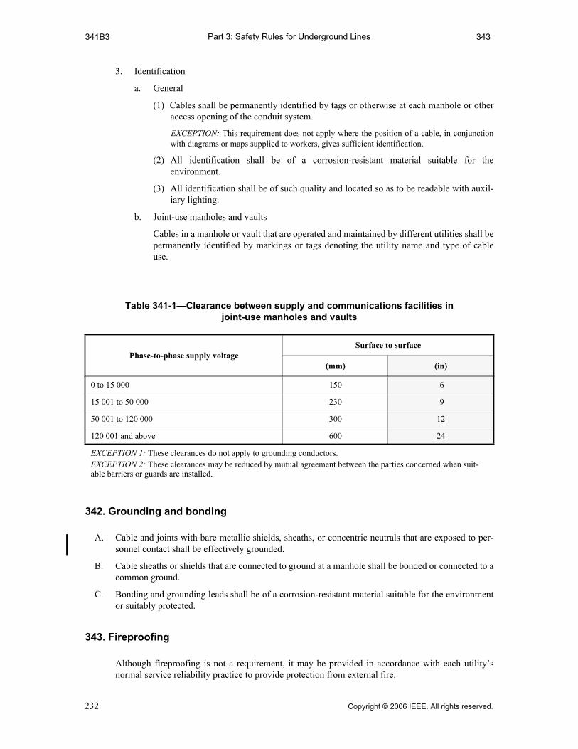
Part 3: Safety Rules for Underground Lines341B3 343
3. Identification
a. General
(1) Cables shall be permanently identified by tags or otherwise at each manhole or otheraccess opening of the conduit system.
EXCEPTION: This requirement does not apply where the position of a cable, in conjunctionwith diagrams or maps supplied to workers, gives sufficient identification.
(2) All identification shall be of a corrosion-resistant material suitable for theenvironment.
(3) All identification shall be of such quality and located so as to be readable with auxil-iary lighting.
b. Joint-use manholes and vaults
Cables in a manhole or vault that are operated and maintained by different utilities shall bepermanently identified by markings or tags denoting the utility name and type of cableuse.
342. Grounding and bonding
A. Cable and joints with bare metallic shields, sheaths, or concentric neutrals that are exposed to per-sonnel contact shall be effectively grounded.
B. Cable sheaths or shields that are connected to ground at a manhole shall be bonded or connected to acommon ground.
C. Bonding and grounding leads shall be of a corrosion-resistant material suitable for the environmentor suitably protected.
343. Fireproofing
Although fireproofing is not a requirement, it may be provided in accordance with each utility’snormal service reliability practice to provide protection from external fire.
Table 341-1—Clearance between supply and communications facilities in joint-use manholes and vaults
Phase-to-phase supply voltageSurface to surface
(mm) (in)
0 to 15 000 150 6
15 001 to 50 000 230 9
50 001 to 120 000 300 12
120 001 and above 600 24
EXCEPTION 1: These clearances do not apply to grounding conductors. EXCEPTION 2: These clearances may be reduced by mutual agreement between the parties concerned when suit-able barriers or guards are installed.
232 Copyright © 2006 IEEE. All rights reserved.

Part 3: Safety Rules for Underground Lines344 344A6
344. Communication cables containing special supply circuits
A. Special circuits operating at voltages in excess of 90 V ac or 150 V dc and used for supplying powersolely to communications equipment may be included in communication cables under the followingconditions:
1. Such cables shall have a conductive sheath or shield that shall be effectively grounded and eachsuch circuit shall be carried on conductors that are individually enclosed with an effectivelygrounded shield.
2. All circuits in such cables shall be owned or operated by one party and shall be maintained onlyby qualified personnel.
3. Supply circuits included in such cables shall be terminated at points accessible only to qualifiedemployees.
4. Communication circuits brought out of such cables, if they do not terminate in a repeater sta-tion or terminal office, shall be protected or arranged so that in event of a failure within thecable, the voltage on the communication circuit will not exceed 400 V to ground.
5. Terminal apparatus for the power supply shall be so arranged that live parts are inaccessiblewhen such supply circuits are energized.
6. Such cables shall be identified, and the identification shall meet the pertinent requirements ofRule 341B3.
EXCEPTION: The requirements of Rule 344A do not apply to communication circuits where thetransmitted power does not exceed 150 W.
Copyright © 2006 IEEE. All rights reserved. 233
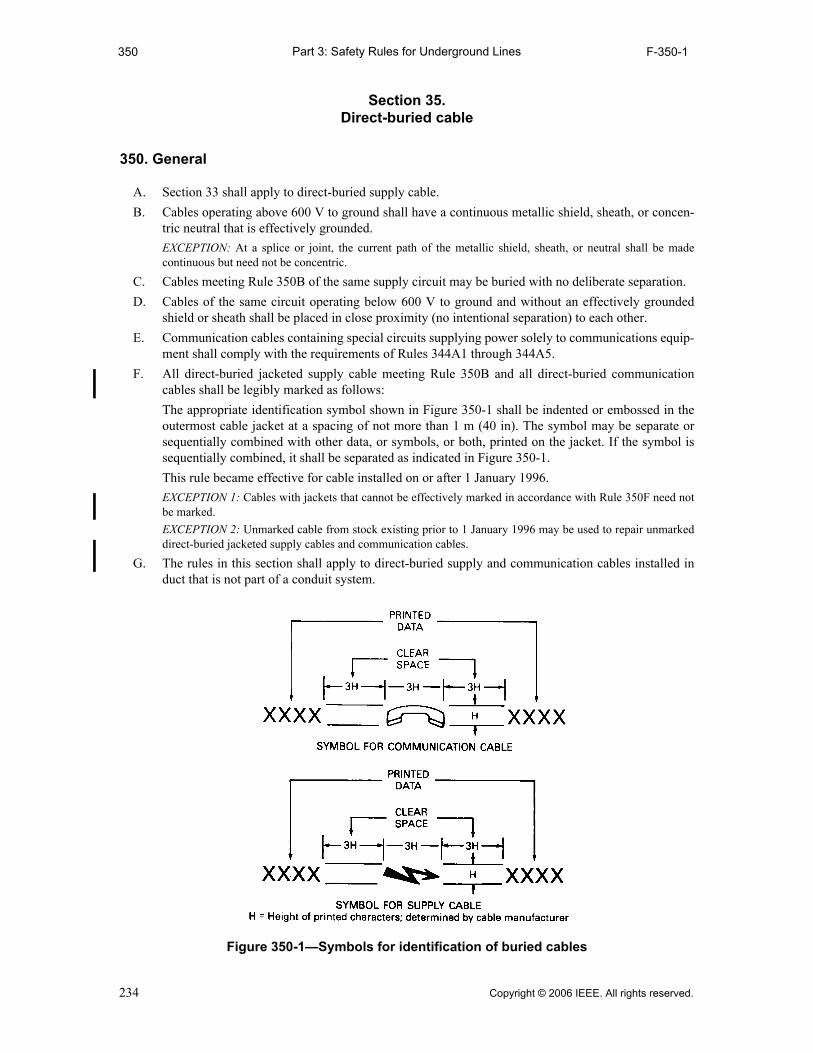
Part 3: Safety Rules for Underground Lines350 F-350-1
Section 35.Direct-buried cable
350. General
A. Section 33 shall apply to direct-buried supply cable.
B. Cables operating above 600 V to ground shall have a continuous metallic shield, sheath, or concen-tric neutral that is effectively grounded.
EXCEPTION: At a splice or joint, the current path of the metallic shield, sheath, or neutral shall be madecontinuous but need not be concentric.
C. Cables meeting Rule 350B of the same supply circuit may be buried with no deliberate separation.
D. Cables of the same circuit operating below 600 V to ground and without an effectively groundedshield or sheath shall be placed in close proximity (no intentional separation) to each other.
E. Communication cables containing special circuits supplying power solely to communications equip-ment shall comply with the requirements of Rules 344A1 through 344A5.
F. All direct-buried jacketed supply cable meeting Rule 350B and all direct-buried communicationcables shall be legibly marked as follows:
The appropriate identification symbol shown in Figure 350-1 shall be indented or embossed in theoutermost cable jacket at a spacing of not more than 1 m (40 in). The symbol may be separate orsequentially combined with other data, or symbols, or both, printed on the jacket. If the symbol issequentially combined, it shall be separated as indicated in Figure 350-1.
This rule became effective for cable installed on or after 1 January 1996.
EXCEPTION 1: Cables with jackets that cannot be effectively marked in accordance with Rule 350F need notbe marked.
EXCEPTION 2: Unmarked cable from stock existing prior to 1 January 1996 may be used to repair unmarkeddirect-buried jacketed supply cables and communication cables.
G. The rules in this section shall apply to direct-buried supply and communication cables installed induct that is not part of a conduit system.
Figure 350-1—Symbols for identification of buried cables
234 Copyright © 2006 IEEE. All rights reserved.
Part 3: Safety Rules for Underground Lines351 351C5
351. Location and routing
A. General
1. Cables should be located so as to be subject to the least disturbance practical. When cables areto be installed parallel to and directly over or under other subsurface structures, the rules onseparation in Rule 353 or 354, as applicable, shall be followed.
2. Cables should be installed in as straight and direct a line as practical. Where bends are required,the bending radius shall be sufficiently large to limit the likelihood of damage to the cablebeing installed.
3. Cable systems should be routed so as to allow safe access for construction, inspection, andmaintenance.
4. The location of structures in the path of the projected cable route shall, as far as practical, bedetermined prior to trenching, plowing, or boring operation.
B. Natural hazards
Routes through unstable soil such as mud, shifting soils, corrosive soils, or other natural hazardsshould be avoided. If burying is required through areas with natural hazards, the cables shall beconstructed and installed in such a manner as to protect them from damage. Such protectivemeasures should be compatible with other installations in the area.
C. Other conditions
1. Swimming pools (in-ground)
Supply cable should not be installed within 1.5 m (5 ft) horizontally of a swimming pool or itsauxiliary equipment. If 1.5 m (5 ft) is not attainable, supplemental mechanical protection shallbe provided.
NOTE: For aboveground pools, see Rule 351C2.
2. Buildings and other structures
Cable should not be installed directly under the foundations of buildings or other structures.Where a cable must be installed under such a structure, the foundation shall be suitablysupported to limit the likelihood of transfer of a detrimental load onto the cable.
3. Railroad tracks
a. The installation of cable longitudinally under the ballast section for railroad tracks shouldbe avoided. Where cable must be installed longitudinally under the ballast section of arailroad, it should be located at a depth of not less than 1.27 m (50 in) below the top of therail.
EXCEPTION: Where this is impractical, or for other reasons, this clearance may be reduced byagreement between the parties concerned.
NOTE: Where unusual conditions exist or where proposed construction would interfere with exist-ing installations, a greater depth than specified above would be required.
b. Where a cable crosses under railroad tracks, the same clearances indicated in Rule 320A5shall apply.
4. Highways and streets
The installation of cable longitudinally under traveled surfaces of highways and streets shouldbe avoided. When cable must be installed longitudinally under the roadway, it should beinstalled in the shoulder or, if this is not practical, within the limits of one lane of traffic to theextent practical.
5. Submarine crossings
Submarine crossings should be routed, installed, or both, so they will be protected from erosionby tidal action or currents. They should not be located where ships normally anchor.
Copyright © 2006 IEEE. All rights reserved. 235

Part 3: Safety Rules for Underground Lines352 T-352-1
352. Installation
A. Trenching
The bottom of the trench receiving direct-buried cable should be relatively smooth, undisturbedearth; well-tamped earth; or sand. When excavation is in rock or rocky soils, the cable should be laidon a protective layer of well-tamped backfill. Backfill within 100 mm (4 in) of the cable should befree of materials that may damage the cable. Backfill should be adequately compacted. Machinecompaction should not be used within 150 mm (6 in) of the cable.
B. Plowing
1. Plowing in of cable in soil containing rock or other solid material should be done in such amanner that the solid material will not damage the cable, either during the plowing operation orafterward.
2. The design of cable-plowing equipment and the plowing-in operation should be such that thecable will not be damaged by bending, side-wall pressure, or excessive cable tension.
C. Boring
Where a cable system is to be installed by boring and the soil and surface loading conditions aresuch that solid material in the region may damage the cable, the cable shall be adequately protected.
D. Depth of burial
1. The distance between the top of a cable and the surface under which it is installed (depth ofburial) shall be sufficient to protect the cable from damage imposed by expected surface usage.
2. Burial depths as indicated in Table 352-1 are considered adequate for supply cables or conduc-tors, except as noted in a, b, or c following:
a. In areas where frost conditions could damage cables, greater burial depths than indicatedabove may be desirable.
b. Lesser depths than indicated above may be used where supplemental protection is pro-vided. The supplemental protection should be sufficient to protect the cable from damageimposed by expected surface usage.
c. Where the surface under which a cable is to be installed is not to final grade, the cableshould be placed so as to meet or exceed the requirements indicated above, both at thetime of installation and subsequent thereto.
E. Supply cables shall not be installed in the same duct with communication cables unless all of thecables are operated and maintained by the same utility.
F. Communication cables may be installed together in the same duct provided all utilities involved arein agreement.
Table 352-1—Supply cable or conductor burial depth(See Rule 352D.)
Voltage (phase-to-phase)Depth of burial
(mm) (in)
0 to 600 600 24
601 to 50 000 750 30
50 001 and above 1070 42
EXCEPTION: Where conflicts with other underground facilities exist, street and area lighting cables operating at notmore than 150 V to ground may be buried at a depth not less than 450 mm (18 in).
236 Copyright © 2006 IEEE. All rights reserved.

Part 3: Safety Rules for Underground Lines353 354B
353. Deliberate separations—Equal to or greater than 300 mm (12 in) from under-ground structures or other cables
A. General
1. These rules apply to a radial separation of supply and communication cables or conductorsfrom each other and from other underground structures such as sewers, water lines, gas andother lines that transport flammable material, building foundations, steam lines, etc., when sep-aration is equal to or greater than 300 mm (12 in).
NOTE: For radial separation less than 300 mm (12 in) see Rule 354.
2. The radial separation should be adequate to permit access to and maintenance of either facilityto limit damage to the other.
B. Crossings
1. Where a cable crosses under another underground structure, the structure shall be suitably sup-ported to limit the likelihood of transferring of a detrimental load onto the cable system.
2. Where a cable crosses over another underground structure, the cable shall be suitably supportedto limit the likelihood of transferring a detrimental load onto the structure.
3. Adequate support may be provided by installing the facilities with sufficient verticalseparation.
C. Parallel facilities
Where a cable system is to be installed directly over and parallel to another underground structure(or another underground structure installed directly over and parallel to a cable), it may be doneproviding all parties are in agreement as to the method. Adequate vertical separation shall bemaintained to permit access to and maintenance of either facility without damage to the other cables.
D. Thermal protection
Cable should be installed with sufficient separation from other underground structures, such assteam or cryogenic lines, to avoid thermal damage to the cable. Where it is not practical to provideadequate clearance, a suitable thermal barrier shall be placed between the two facilities.
354. Random separation—Separation less than 300 mm (12 in) from underground structures or other cables
A. General
1. These rules apply to a radial separation of supply and communication cables or conductorsfrom each other and from other underground structures when the radial separation betweenthem will be less than 300 mm (12 in).
2. Radial separation of supply and communications cables or conductors from steam lines, gas,and other lines that transport flammable material shall be not less than 300 mm (12 in) and shallmeet Rule 353.
3. Supply circuits operating above 300 V to ground or 600 V between conductors shall be soconstructed, operated, and maintained that when faulted, they shall be promptly de-energizedinitially or following subsequent protective device operation (phase-to-ground faults forgrounded circuits, phase-to-phase faults for ungrounded circuits).
4. Communication cables and conductors, and supply cables and conductors buried in randomseparation may be treated as one system when considering separation from other undergroundstructures or facilities.
B. Supply cables or conductors
The cables or conductors of a supply circuit and those of another supply circuit may be buriedtogether at the same depth with no deliberate separation between facilities, provided all partiesinvolved are in agreement.
Copyright © 2006 IEEE. All rights reserved. 237

Part 3: Safety Rules for Underground Lines354C 354D2a(3)
C. Communication cables or conductors
The cables or conductors of a communication circuit and those of another communication circuitmay be buried together and at the same depth with no deliberate separation between facilities,provided all parties involved are in agreement.
D. Supply and communication cables or conductors
Supply cables or conductors and communication cables or conductors may be buried together at thesame depth, with no deliberate separation between facilities, provided all parties involved are inagreement and the applicable rules in 354D1 are met and either Rule 354D2 or 354D3 is met.
EXCEPTION: Entirely dielectric fiber-optic communication cables may be buried together at the same depthwith no deliberate separation from supply cables or conductors provided all parties involved are in agreementand Rules 354D1a, b, c, and d are met.
1. General
a. Grounded supply systems shall not be operated in excess of 22 000 V to ground.
b. Ungrounded supply systems shall not be operated in excess of 5300 V phase to phase.
c. Cables of an ungrounded supply system operating above 300 V shall be of effectivelygrounded concentric shield construction. Such cables shall be maintained in close proxim-ity to each other.
d. Ungrounded supply circuits operating above 300 V between conductors and in randomseparation with communication conductors shall be equipped with a ground-fault indica-tion system.
e. Communication cables and communication service wire having metallic conductors ormetallic components shall have a continuous metallic shield under the outer jacket.
EXCEPTION: This requirement does not apply to Rule 354C.
f. Communications-protective devices shall be adequate for the voltage and currentsexpected to be impressed on them in the event of contact with the supply conductors.
g. Adequate bonding shall be provided between the effectively grounded supply conductoror conductors and the communication cable shield or sheath at intervals that should notexceed 300 m (1000 ft).
h. In the vicinity of supply stations where large ground currents may flow, the effect of thesecurrents on communication circuits should be evaluated before communication cables areplaced in random separation with supply cables.
2. Grounded bare or semiconducting jacketed neutral supply cables
a. A supply facility operating above 300 V to ground shall include a bare or semiconductingjacketed grounded conductor in continuous contact with the earth. This conductor, ade-quate for the expected magnitude and duration of the fault current that may be imposed,shall be one of the following:
(1) A sheath, an insulation shield, or both
(2) Multiple concentric conductors closely spaced circumferentially
(3) A separate conductor in contact with the earth and in close proximity to the cable,where such cable or cables also have a grounded sheath or shield not necessarily incontact with the earth. The sheath, shield, or both, as well as the separate conductor,shall be adequate for the expected magnitude and duration of the fault currents thatmay be imposed.
NOTE: This is applicable when a cable in nonmetallic duct is considered as a direct-buriedcable installation and random separation is desired.
EXCEPTION: Where buried cable passes through a short section of conduit such as under aroadway, the contact with earth of the grounded conductor can be omitted, provided thegrounded conductor is continuous through the conduit.
238 Copyright © 2006 IEEE. All rights reserved.
Part 3: Safety Rules for Underground Lines354D2b 354E3
b. The bare conductor or conductors in contact with the earth shall be of suitable corrosion-resistant material. The conductor covered by a semiconducting jacket shall be compatiblewith the jacketing compound.
NOTE: Experience has shown that in many geographic areas, bare concentric copper neutral con-ductors experience severe corrosion.
c. The radial resistivity of the semiconducting jacket shall be not more than 100 Ω • m andshall remain essentially stable in service. The radial resistivity of the jacket material is thatvalue calculated from measurements on a unit length of cable, of the resistance betweenthe concentric neutral and a surrounding conducting medium. Radial resistivity is equal tothe resistance of a unit length times the surface area of the jacket divided by the averagethickness of the jacket over the neutral conductors. All dimensions are to be expressed inmeters.
3. Insulating jacketed grounded neutral supply cables
Each phase conductor of a multi-grounded supply system operating above 300 V to ground andhaving an overall insulating jacket shall have an effectively grounded copper concentricconductor meeting all of the following requirements:
a. A conductance not less than one half that of the phase conductor
b. Adequate for the expected magnitude and duration of fault current that may be imposed
c. Grounded in accordance with Rule 314 except that the grounding interval required byRule 96C shall be not less than eight in each 1.6 km (1 mile) of the random buried section,not including grounds at individual services
4. Insulating jacketed grounded neutral supply cables in nonmetallic duct
Insulating jacketed grounded neutral supply cables meeting the rules of 354D3, when installedin nonmetallic duct, may be random-laid with communication cables.
E. Supply and communication cables or conductors and non-metallic water and sewer lines
1. Supply cables and conductors and non-metallic water and sewer lines may be buried togetherwith no deliberate separation between facilities and at the same depth, provided all partiesinvolved are in agreement.
2. Communication cables and conductors and non-metallic water and sewer lines may be buriedtogether with no deliberate separation between facilities and at the same depth, provided allparties involved are in agreement.
3. Supply cables or conductors, communication cables or conductors, non-metallic water andsewer lines may be buried together with no deliberate separation between facilities and at thesame depth, provided the applicable rules in Rule 354D are met and all parties involved are inagreement.
Copyright © 2006 IEEE. All rights reserved. 239

Part 3: Safety Rules for Underground Lines360 363B
Section 36.Risers
360. General
A. Mechanical protection for supply conductors or cables shall be provided as required by Rule 239Dof this Code. This protection should extend at least 300 mm (1 ft) below ground level.
B. Supply conductors or cable should rise vertically from the cable trench with only such deviation asnecessary to permit a reasonable cable-bending radius.
C. Exposed conductive pipes or guards containing supply conductors or cables shall be grounded inaccordance with Rule 314.
361. Installation
A. The installation should be designed so that water does not stand in riser pipes above the frost line.
B. Conductors or cables shall be supported in a manner designed to limit the likelihood of damage toconductors, cables, or terminals.
C. Where conductors or cables enter the riser pipe or elbow, they shall be installed in such a mannerthat shall minimize the possibility of damage due to relative movement of the cable and pipe.
362. Pole risers—Additional requirements
A. Risers should be located on the pole in the safest available position with respect to climbing spaceand exposure to traffic damage.
B. The number, size, and location of riser ducts or guards shall be limited to allow adequate access forclimbing.
363. Pad-mounted installations
A. Supply conductors or cables rising from the trench to transformers, switchgear, or other equipmentmounted on pads shall be so placed and arranged that they will not bear on the edges of holesthrough the pad nor the edges of bends or other duct work below the pad.
B. Cable entering pad-mounted equipment shall be maintained substantially at adequate depth for thevoltage class until it becomes protected by being directly under the pad, unless other suitablemechanical protection is provided.
240 Copyright © 2006 IEEE. All rights reserved.

Part 3: Safety Rules for Underground Lines370 374B
Section 37.Supply cable terminations
370. General
A. Cable terminations shall be designed and constructed to meet the requirements of Rule 333.
B. Riser terminations not located within a vault, pad-mounted equipment, or similar enclosure shall beinstalled in a manner designed to ensure that the clearance specified in Parts 1 and 2 of this Code aremaintained.
C. A cable termination shall be designed to limit the likelihood of moisture penetration into the cablewhere such penetration is detrimental to the cable.
D. Where clearances between parts at different potentials are reduced below those adequate for thevoltage and BIL (basic impulse insulation level), suitable insulating barriers or fully insulated termi-nals shall be provided to meet the required equivalent clearances.
371. Support at terminations
A. Cable terminations shall be installed in a manner designed to maintain their installed position.
B. Where necessary, cable shall be supported or secured in a manner designed to limit the likelihood ofthe transfer of damaging mechanical stresses to the termination, equipment, or structure.
372. Identification
Suitable circuit identification shall be provided for all terminations.
EXCEPTION: This requirement does not apply where the position of the termination, in conjunction withdiagrams or maps supplied to workers, gives sufficient identification.
373. Clearances in enclosures or vaults
A. Adequate electrical clearances of supply terminations shall be maintained, both between conductorsand between conductors and ground, consistent with the type of terminator used.
B. Where exposed live parts are in an enclosure, clearances or insulating barriers adequate for the volt-ages and the design BIL shall be provided.
C. Where a termination is in a vault, uninsulated live parts are permissible provided they are guarded orisolated.
374. Grounding
A. All exposed conducting surfaces of the termination device, other than live parts and equipment towhich it is attached, shall be effectively grounded, bonded, or both.
B. Conductive structures supporting cable terminations shall be effectively grounded.
EXCEPTION: Grounding, bonding, or both is not required where the above parts are isolated or guarded.
Copyright © 2006 IEEE. All rights reserved. 241

Part 3: Safety Rules for Underground Lines380 381G2
Section 38.Equipment
380. General
A. Equipment includes:
1. Buses, transformers, switches, etc., installed for the operation of the electric supply system
2. Repeaters, loading coils, etc., installed for the operation of the communications system
3. Auxiliary equipment, such as sump pumps, convenience outlets, etc., installed incidental to thepresence of the supply or communications systems
B. Where equipment is to be installed in a joint-use manhole, it shall be done with the concurrence ofall parties concerned.
C. Supporting structures, including racks, hangers, or pads and their foundations, shall be designed tosustain all loads and stresses expected to be imposed by the supported equipment including thosestresses caused by its operation.
D. Pad-mounted equipment, pedestals, and other aboveground enclosures, should be located not lessthan 1.2 m (4 ft) from fire hydrants.
EXCEPTION: Where conditions do not permit a clearance of 1.2 m (4 ft), a clearance of not less than 900 mm(3 ft) is allowed.
381. Design
A. The expected thermal, chemical, mechanical, and environmental conditions at the location shall beconsidered in the design of all equipment and mountings.
B. All equipment, including auxiliary devices, shall be designed to withstand the effects of normal,emergency, and fault conditions expected during operation.
C. Switches shall be provided with clear indication of contact position, and the handles or activatingdevices clearly marked to indicate operating directions.
RECOMMENDATION: The handles or control mechanism of all switches throughout the system shouldoperate in a like direction to open and in a uniformly different direction to close in order to minimize errors.
D. Remotely controlled or automatic devices shall have local provisions to render remote or automaticcontrols inoperable if such operation may result in a hazard to the worker.
E. Enclosures containing fuses and interrupter contacts shall be designed to withstand the effects ofnormal, emergency, and fault conditions expected during operation.
F. When tools are to be used to connect or disconnect energized devices, space or barriers shall bedesigned to provide adequate clearance from ground or between phases.
G. Pad-mounted and other aboveground equipment
1. Pad-mounted and other aboveground equipment shall have an enclosure that is either locked orotherwise secured against unauthorized entry.
2. Access to exposed live parts in excess of 600 V shall require two separate conscious acts. Thefirst shall be the opening of a door or barrier that is locked or otherwise secured against unau-thorized entry as required by Rule 381G1. The second act shall be either the opening of a dooror the removal of a barrier.
RECOMMENDATION: A prominent and appropriate safety sign should be visible when the first door orbarrier is opened or removed.
NOTE: ANSI Z535.1-2006, ANSI Z535.2-2006, ANSI Z535.3-2006, ANSI Z535.4-2006, andANSI Z535.5-2006 contain information regarding safety signs.
242 Copyright © 2006 IEEE. All rights reserved.

Part 3: Safety Rules for Underground Lines382 385
382. Location in underground structures
A. Equipment shall not obstruct personnel access openings in manholes or vaults, nor shall it impedeegress by persons working in the structures containing the equipment.
B. Equipment shall not be installed closer than 200 mm (8 in) to the back of fixed ladders and shall notinterfere with the proper use of such ladders.
C. Equipment should be arranged in a manhole or vault to permit installation, operation, and mainte-nance of all items in such structures.
D. Switching devices that have provision for manual or electrical operation shall be operable from asafe position. This may be accomplished by use of portable auxiliary devices, temporarily attached.
E. Equipment should not interfere with drainage of the structure.
F. Equipment shall not interfere with the ability to ventilate any structure or enclosure.
383. Installation
A. Provisions for lifting, rolling to final position, and mounting shall be adequate for the weight of thedevice.
B. Live parts shall be guarded or isolated to limit the likelihood of contact by persons in a normal posi-tion adjacent to the equipment.
C. Operating levers, inspection facilities, and test facilities shall be visible and readily accessible whenequipment is in final location without moving permanent connections.
D. Live parts shall be isolated or protected from exposure to conducting liquids or other materialexpected to be present in the structure containing the equipment.
E. Operating controls of supply equipment, readily accessible to unauthorized personnel, shall besecured by bolts, locks, or seals.
384. Grounding and bonding
A. Cases and enclosures made of conductive material shall be effectively grounded or guarded.
B. Guards constructed of conductive material shall be effectively grounded.
C. Bonding should be provided between all aboveground metallic power and communicationsapparatus (pedestals, terminals, apparatus cases, transformer cases, etc.) that are separated by adistance of 1.8 m (6 ft) or less. For the purpose of this rule, pole grounds are not considered anaboveground metallic power apparatus and therefore not required to be bonded to thecommunication apparatus.
385. Identification
Where transformers, regulators, or other similar equipment operate in multiple, tags, diagrams, orother suitable means shall be used to indicate that fact.
Copyright © 2006 IEEE. All rights reserved. 243
Part 3: Safety Rules for Underground Lines390 391B3
Section 39.Installation in tunnels
390. General
A. The installation of supply and communications facilities in tunnels shall meet the applicable require-ments contained elsewhere in Part 3 of this Code as supplemented or modified by this section.
B. Where the space occupied by supply or communications facilities in a tunnel is accessible to otherthan qualified persons, or where supply conductors do not meet the requirements of Part 3 of thisCode for cable systems, the installation shall be in accordance with the applicable requirements ofPart 2 of this Code.
C. All parties concerned must be in agreement with the design of the structure and designs proposed forinstallations within it.
391. Environment
A. When the tunnel is accessible to the public or when workers must enter the structure to install, oper-ate, or maintain the facilities in it, the design shall provide a controlled safe environment including,where necessary, barriers, detectors, alarms, ventilation, pumps, and adequate safety devices for allfacilities. Controlled safe environment shall include the following:
1. Design to avoid poisonous or suffocation atmosphere
2. Design to protect persons from pressurized lines, fire, explosion, and high temperatures
3. Design to avoid unsafe conditions due to induced voltages
4. Design to limit the likelihood of hazards due to flooding
5. Design to ensure egress; two directions for egress shall be provided for all points in tunnels
6. Working space, in accordance with Rule 323B, the boundary of which shall be not less than600 mm (2 ft) from a vehicular operating space or from exposed moving parts of machinery
7. Safeguards designed to protect workers from hazards due to the operation of vehicles or othermachinery in tunnels
8. Unobstructed walkways for workers in tunnels
B. A condition of occupancy in multiple-use tunnels by supply and communications facilities shall bethat the design and installation of all facilities is coordinated to provide a safe environment for theoperation of supply facilities, communications facilities, or both. Safe environment for facilitiesshall include the following:
1. Means to protect equipment from harmful effects of humidity or temperature
2. Means to protect equipment from harmful effects of liquids or gases
3. Coordinated design and operation of corrosion-control systems
244 Copyright © 2006 IEEE. All rights reserved.

Part 4: Rules for the Operation of Electric Lines400 402
Part 4.Rules for the Operation of Electric Supply
and Communications Lines and Equipment
Section 40.Purpose and scope
400. Purpose
The purpose of Part 4 of this Code is to provide practical work rules as one of the means ofsafeguarding employees and the public from injury. It is not the intent of these rules to requireunreasonable steps to comply; however, all reasonable steps shall be taken.
401. Scope
Part 4 of this Code covers work rules to be followed in the installation, operation, and maintenanceof electric supply and communications systems.
402. Referenced sections
The Introduction (Section 1), Definitions (Section 2), References (Section 3), and Groundingmethods (Section 9) of this Code shall apply to the requirements of Part 4.
The standards listed in Section 3 shall be used with Part 4 where applicable.
NOTE: After ANSI C2-1973 [B6] was originally approved, 30 June 1972, the US Occupational Safety andHealth Administration (OSHA) issued 29 CFR 1926, Subpart V [B62], applying to employee safety inconstruction. The differences between this document and the editions of the NESC through the 1993 Editionwere noted in footnotes to the text of Part 4.
In 1989, OSHA published in the Federal Register [01/31/89], vol. 54, no. 19, pp. 4974–5024 inclusive, DocketS–015 [B65], a Notice of Proposed Rulemaking to issue new regulations as 29 CFR 1910.137 and 29 CFR1910.269 to address the work practices to be used during the operation and maintenance of generation,transmission, and distribution facilities. Coordination between these OSHA proposals and the 1997 Edition ofthe NESC has been effected such that the technical content of each document is harmonized at this time to theextent possible with the closure of the rulemaking hearing docket. In some cases, it was thus not possible for theOSHA final rule published as 29 CFR 1910.137 and 29 CFR 1910.269 (as published in the Federal Register,[01/31/94] vol. 59, no. 20, pp. 4321–4477 [B66]) to address all the technical information considered in thisrevision of NESC Part 4.
Copyright © 2006 IEEE. All rights reserved. 245

Part 4: Rules for the Operation of Electric Lines410 410A5
Section 41.Supply and communications systems—Rules for employers
410. General requirements
A. General
1. The employer shall inform each employee working on or about communications equipment orelectric supply equipment and the associated lines, of the safety rules governing the employee’sconduct while so engaged.
When deemed necessary, the employer shall provide a copy of such rules.
2. The employer shall provide training to all employees who work in the vicinity of exposedenergized facilities. The training shall include applicable work rules required by this Part andother mandatory referenced standards or rules. The employer shall ensure that each employeehas demonstrated proficiency in required tasks. The employer shall provide retraining for anyemployee who, as a result of routine observance of work practices, is not following work rules.
3. Effective as of January 1, 2009, the employer shall ensure that an assessment is performed todetermine potential exposure to an electric arc for employees who work on or near energizedparts or equipment. If the assessment determines a potential employee exposure greater than2 cal/cm2 exists (see Neal, Bingham, and Doughty [B59]), the employer shall requireemployees to wear clothing or a clothing system that has an effective arc rating not less than theanticipated level of arc energy.
When exposed to an electric arc or flame, clothing made from the following materials shall notbe worn: acetate, nylon, polyester, or polypropylene.
The effective arc rating of clothing or a clothing system to be worn at voltages 1000 V andabove shall be determined using Tables 410-1 and 410-2 or performing an arc hazard analysis.
When an arc hazard analysis is performed, it shall include a calculation of the estimated arcenergy based on the available fault current, the duration of the arc (cycles), and the distancefrom the arc to the employee.
EXCEPTION 1: If the clothing required by this rule has the potential to create additional and greater haz-ards than the possible exposure to the heat energy of the electric arc, then clothing with an arc rating or arcthermal performance value (ATPV) less than that required by the rule can be worn.
EXCEPTION 2: For secondary systems below 1000 V, applicable work rules required by this part andengineering controls shall be utilized to limit exposure. In lieu of performing an arc hazard analysis, cloth-ing or a clothing system with a minimum effective arc rating of 4 cal/cm2 shall be required to limit thelikelihood of ignition.
NOTE 1: A clothing system (multiple layers) that includes an outer layer of flame resistant material andan inner layer of non-flame resistant material has been shown to block more heat than a single layer. Theeffect of the combination of these multiple layers can be referred to as the effective arc rating.
NOTE 2: It is recognized that arc energy levels can be excessive with secondary systems. Applicablework rules required by this part and engineering controls should be utilized.
4. Employers shall utilize positive procedures to secure compliance with these rules. Cases mayarise, however, where the strict enforcement of some particular rule could seriously impede thesafe progress of the work at hand; in such cases the employee in charge of the work to be doneshould make such temporary modification of the rules as will accomplish the work withoutincreasing the hazard.
5. If a difference of opinion arises with respect to the application of these rules, the decision of theemployer or the employer’s authorized agent shall be final. This decision shall not result in anyemployee performing work in a manner that is unduly hazardous to the employee or to theemployee’s fellow workers.
246 Copyright © 2006 IEEE. All rights reserved.

Part 4: Rules for the Operation of Electric Lines410B T-410-1
B. Emergency procedures and first aid rules
1. Employees shall be informed of procedures to be followed in case of emergencies and rules forfirst aid, including approved methods of resuscitation. Copies of such procedures and rulesshould be kept in conspicuous locations in vehicles and places where the number of employeesand the nature of the work warrants.
2. Employees working on communications or electric supply equipment or lines shall be regularlyinstructed in methods of first aid and emergency procedures, if their duties warrant suchtraining.
C. Responsibility
1. A designated person shall be in charge of the operation of the equipment and lines and shall beresponsible for their safe operation.
2. If more than one person is engaged in work on or about the same equipment or line, one personshall be designated as in charge of the work to be performed. Where there are separate worklocations, one person may be designated at each location.
Table 410-1—Clothing and clothing systems—voltage, fault current, and maximum clearing time for voltages 1 to 46 kV q
(See Rule 410A3.)
Phase-to-phase voltage
(kV)
Fault current (kA)
4-cal system 8-cal system 12-cal system
Maximum clearing time
(cycles)
Maximumclearing time
(cycles)
Maximumclearing time
(cycles)
1 to 15 5 46.5 93.0 139.5
10 18.0 36.1 54.1
15 10.0 20.1 30.1
20 6.5 13.0 19.5
15.1 to 25 5 27.6 55.2 82.8
10 11.4 22.7 34.1
15 6.6 13.2 19.8
20 4.4 8.8 13.2
25.1 to 36 5 20.9 41.7 62.6
10 8.8 17.6 26.5
15 5.2 10.4 15.7
20 3.5 7.1 10.6
Copyright © 2006 IEEE. All rights reserved. 247

Part 4: Rules for the Operation of Electric LinesT-410-1 T-410-2
36.1 to 46 5 16.2 32.4 48.6
10 7.0 13.9 20.9
15 4.3 8.5 12.8
20 3.0 6.1 9.1
qThese calculations are based on open air phase-to-ground arc. This table is not intended for phase-to-phase arcsor enclosed arcs (arc in a box).These calculations are based on a 15-in separation distance from the arc to the employee and arc gaps as follows:1 to 15 kV = 2 in, 15.1 to 25 kV = 4 in, 25.1 to 36 kV = 6 in, 36.1 to 46 kV = 9 in. See IEEE Std 4-1995.These calculations were derived using a commercially available computer software program. Other methods areavailable to estimate arc exposure values and may yield slightly different but equally acceptable results.The use of the table in the selection of clothing is intended to reduce the amount or degree of injury but may notprevent all burns.
Table 410-2—Live-line tool work clothing and clothing systems—voltage, fault current, and maximum clearing time for voltages 46.1 to 800 kV q
(See Rule 410A3.)
Phase-to-phase voltage
(kV)
Fault current (kA)
4-cal system 8-cal system 12-cal system
Maximumclearing time
(cycles)
Maximumclearing time
(cycles)
Maximumclearing time
(cycles)
46.1 to 72.5 20 8.5 17.0 25.5
30 5.3 10.5 15.8
40 3.7 7.3 11.0
50 2.8 5.5 8.3
72.6 to 121 20 8.2 16.5 24.7
30 4.7 9.4 14.1
40 3.1 6.2 9.3
50 2.2 4.4 6.6
138 to 145 20 9.8 19.5 29.3
30 5.6 11.2 16.8
40 3.7 7.4 11.1
50 2.6 5.3 7.9
Table 410-1—Clothing and clothing systems—voltage, fault current, and maximum clearing time for voltages 1 to 46 kV q (continued)
(See Rule 410A3.)
Phase-to-phase voltage
(kV)
Fault current (kA)
4-cal system 8-cal system 12-cal system
Maximum clearing time
(cycles)
Maximumclearing time
(cycles)
Maximumclearing time
(cycles)
248 Copyright © 2006 IEEE. All rights reserved.

Part 4: Rules for the Operation of Electric LinesT-410-2 T-410-2
161 to 169 20 9.3 18.6 27.9
30 5.7 11.5 17.2
40 4.0 8.0 12.0
50 3.0 6.0 9.0
230 to 242 20 10.4 20.9 31.3
30 6.4 12.9 19.3
40 4.5 9.0 13.5
50 3.4 6.8 10.1
345 to 362 20 22.6 45.3 67.9
30 14.0 28.1 42.1
40 9.8 19.6 29.4
50 7.4 14.7 22.1
500 to 550 20 18.9 37.8 56.7
30 11.7 23.3 35.0
40 8.1 16.3 24.4
50 6.1 12.2 18.3
765 to 800 20 43.6 87.3 130.9
30 27.0 53.9 80.9
40 18.9 37.8 56.7
50 14.2 28.4 42.6
qArc gap—calculated by using the phase-to-ground voltage of the circuit and dividing by 10. The dielectricstrength of air is taken at 10 kV per inch. See IEEE Std 4-1995.
Distance from arc—calculated by using the minimum approach distance from Table 441-2 and subtracting twotimes the assumed arc gap length.
These calculations were derived using a commercially available computer software program. Other methods areavailable to estimate arc exposure values and may yield slightly different, but equally acceptable results.
The use of the table in the selection of clothing is intended to reduce the amount or degree of injury but may notprevent all burns.
Table 410-2—Live-line tool work clothing and clothing systems—voltage, fault current, and maximum clearing time for voltages 46.1 to 800 kV q (continued)
(See Rule 410A3.)
Phase-to-phase voltage
(kV)
Fault current (kA)
4-cal system 8-cal system 12-cal system
Maximumclearing time
(cycles)
Maximumclearing time
(cycles)
Maximumclearing time
(cycles)
Copyright © 2006 IEEE. All rights reserved. 249
Part 4: Rules for the Operation of Electric Lines411 411E
411. Protective methods and devices
A. Methods
1. Access to rotating or energized equipment shall be restricted to authorized personnel.
2. Diagrams, showing plainly the arrangement and location of the electric supply equipment andlines, shall be maintained on file and shall be readily available to authorized personnel for thatportion of the system for which they are responsible.
3. Employees shall be instructed as to the character of the equipment or lines and methods to beused before any work is undertaken thereon.
4. Employees should be instructed to take additional precautions to ensure their safety whenconditions create unusual hazards.
B. Devices and equipment
An adequate supply of protective devices and equipment, sufficient to enable employees to meet therequirements of the work to be undertaken, and first aid equipment and materials shall be availablein readily accessible and, where practical, conspicuous places.
Protective devices and equipment shall conform to the applicable standards listed in Section 3.
NOTE: The following is a list of some common protective devices and equipment, the number and kinds ofwhich will depend upon the requirements of each case:
1. Insulating wearing apparel such as rubber gloves, rubber sleeves, and headgear
2. Insulating shields, covers, mats, and platforms
3. Insulating tools for handling or testing energized equipment or lines
4. Protective goggles
5. Person at work tags, portable danger signs, traffic cones, and flashers
6. Line worker’s body belts, lanyards, and positioning straps
7. Fire-extinguishing equipment designed for safe use on energized parts or plainly marked that they must notbe so used
8. Protective grounding materials and devices
9. Portable lighting equipment
10. First aid equipment and materials
11. Voltage detection devices/meters
C. Inspection and testing of protective devices
1. Protective devices and equipment shall be inspected or tested to ensure that they are in safeworking condition.
2. Insulating gloves, sleeves, and blankets shall be inspected before use. Insulating gloves andsleeves shall be tested as frequently as their use requires.
3. Line-worker’s body belts, lanyards, and positioning straps and other personal equipment,whether furnished by employer or employee, shall be inspected to ensure that they are in safeworking condition.
D. Signs and tags for employee safety
Safety signs and tags required by Part 4 shall comply with the provisions of ANSI Z535.1-2006through ANSI Z535.5-2006, inclusive.
E. Identification and location
Means shall be provided so that identification of supply and communication lines can be determinedbefore work is undertaken. Persons responsible for underground facilities shall be able to indicatethe location of their facilities.
250 Copyright © 2006 IEEE. All rights reserved.

Part 4: Rules for the Operation of Electric Lines411F 411F2
F. Fall protection
1. Employers shall develop, implement, and maintain an effective fall protection program appli-cable to climbing or otherwise accessing and working from elevated work locations, whichshall include all of the following:
a. Training, retraining, and documentation
b. Guidance on equipment selection, inspection, care, and maintenance
c. Considerations concerning structural design and integrity, with particular reference toanchorages and their availability
d. Rescue plans and related training
e. Hazard recognition
2. The employer shall not permit employees the use of 100% leather positioning straps.
Copyright © 2006 IEEE. All rights reserved. 251

Part 4: Rules for the Operation of Electric Lines420 420D
Section 42.General rules for employees
420. Personal general precautions
A. Rules and emergency methods
1. Employees shall carefully read and study the safety rules, and may be called upon at any timeto show their knowledge of the rules.
2. Employees shall familiarize themselves with approved methods of first aid, rescue techniques,and fire extinguishment.
B. Qualifications of employees
1. Employees whose duties require working on or in the vicinity of energized equipment or linesshall perform only those tasks for which they are trained, equipped, authorized, and so directed.Inexperienced employees shall: (a) work under the direction of an experienced and qualifiedperson at the site, and (b) perform only directed tasks.
2. Employees operating mechanized equipment shall be qualified to perform those tasks.
3. If an employee is in doubt as to the safe performance of any assigned work, the employee shallrequest instructions from the employee’s supervisor or person in charge.
4. Employees who do not normally work on or in the vicinity of electric supply lines andequipment but whose work brings them into these areas for certain tasks shall proceed with thiswork only when authorized by a qualified person.
C. Safeguarding oneself and others
1. Employees shall heed safety signs and signals and warn others who are in danger or in thevicinity of energized equipment or lines.
2. Employees shall report promptly to the proper authority any of the following:
a. Line or equipment defects such as abnormally sagging wires, broken insulators, brokenpoles, or lamp supports
b. Accidentally energized objects such as conduits, light fixtures, or guys
c. Other defects that may cause a dangerous condition
3. Employees whose duties do not require them to approach or handle electric equipment andlines shall keep away from such equipment or lines and should avoid working in areas whereobjects and materials may be dropped by persons working overhead.
4. Employees who work on or in the vicinity of energized lines shall consider all of the effects oftheir actions, taking into account their own safety as well as the safety of other employees onthe job site, or on some other part of the affected electric system, the property of others, and thepublic in general.
5. No employee shall approach or bring any conductive object, without a suitable insulatinghandle, closer to any exposed energized part than allowed by Rule 431 (communication) orRule 441 (supply), as applicable.
6. Employees should exercise care when extending metal ropes, tapes, or wires parallel to and inthe proximity of energized high-voltage lines because of induced voltages. When it is necessaryto measure clearances from energized objects, only devices approved for the purpose shall beused.
D. Energized or unknown conditions
Employees shall consider electric supply equipment and lines to be energized, unless they arepositively known to be de-energized. Before starting work, employees shall perform preliminaryinspections or tests to determine existing conditions. Operating voltages of equipment and linesshould be known before working on or in the vicinity of energized parts.
252 Copyright © 2006 IEEE. All rights reserved.
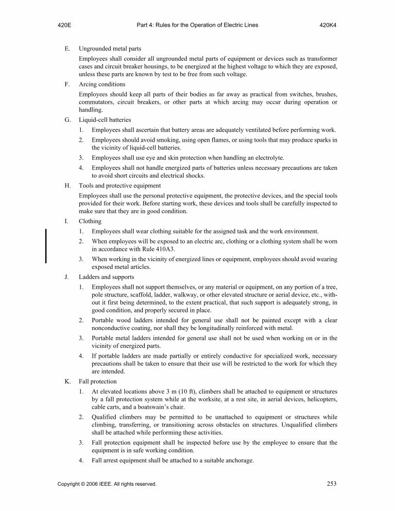
Part 4: Rules for the Operation of Electric Lines420E 420K4
E. Ungrounded metal parts
Employees shall consider all ungrounded metal parts of equipment or devices such as transformercases and circuit breaker housings, to be energized at the highest voltage to which they are exposed,unless these parts are known by test to be free from such voltage.
F. Arcing conditions
Employees should keep all parts of their bodies as far away as practical from switches, brushes,commutators, circuit breakers, or other parts at which arcing may occur during operation orhandling.
G. Liquid-cell batteries
1. Employees shall ascertain that battery areas are adequately ventilated before performing work.
2. Employees should avoid smoking, using open flames, or using tools that may produce sparks inthe vicinity of liquid-cell batteries.
3. Employees shall use eye and skin protection when handling an electrolyte.
4. Employees shall not handle energized parts of batteries unless necessary precautions are takento avoid short circuits and electrical shocks.
H. Tools and protective equipment
Employees shall use the personal protective equipment, the protective devices, and the special toolsprovided for their work. Before starting work, these devices and tools shall be carefully inspected tomake sure that they are in good condition.
I. Clothing
1. Employees shall wear clothing suitable for the assigned task and the work environment.
2. When employees will be exposed to an electric arc, clothing or a clothing system shall be wornin accordance with Rule 410A3.
3. When working in the vicinity of energized lines or equipment, employees should avoid wearingexposed metal articles.
J. Ladders and supports
1. Employees shall not support themselves, or any material or equipment, on any portion of a tree,pole structure, scaffold, ladder, walkway, or other elevated structure or aerial device, etc., with-out it first being determined, to the extent practical, that such support is adequately strong, ingood condition, and properly secured in place.
2. Portable wood ladders intended for general use shall not be painted except with a clearnonconductive coating, nor shall they be longitudinally reinforced with metal.
3. Portable metal ladders intended for general use shall not be used when working on or in thevicinity of energized parts.
4. If portable ladders are made partially or entirely conductive for specialized work, necessaryprecautions shall be taken to ensure that their use will be restricted to the work for which theyare intended.
K. Fall protection
1. At elevated locations above 3 m (10 ft), climbers shall be attached to equipment or structuresby a fall protection system while at the worksite, at a rest site, in aerial devices, helicopters,cable carts, and a boatswain’s chair.
2. Qualified climbers may be permitted to be unattached to equipment or structures whileclimbing, transferring, or transitioning across obstacles on structures. Unqualified climbersshall be attached while performing these activities.
3. Fall protection equipment shall be inspected before use by the employee to ensure that theequipment is in safe working condition.
4. Fall arrest equipment shall be attached to a suitable anchorage.
Copyright © 2006 IEEE. All rights reserved. 253

Part 4: Rules for the Operation of Electric Lines420K5 420N
5. The employee shall determine that all components of the fall protection system are properlyengaged and that the employee is secure in the line-worker’s body belt, harness, or any otherfall protection system.
NOTE: Climbers need to be aware of accidental disengagement of fall protection components. Accidentaldisengagement is the sudden, unexpected release of a positioning strap snaphook from the D-ring of theline-worker’s body belt without the user directly manipulating the latch of the snaphook. In general, thereare two primary reasons for this occurrence.
(a) Foreign objects may open the latch of the snaphook during normal use. It is possible for the snaphookto come in contact with such things as hand lines, guy wires, or other apparatus. These items mayplace pressure on the latch, causing the snaphook to separate from the D-ring without the user’sknowledge. This could cause an accident. The worker must take care to keep the snaphooks awayfrom any potential causes of release. Locking snaphooks reduce the possibility of this occurrence.
(b) Roll-out is the sudden separation of the snaphook/D-ring combination when the snaphook is twistedin the D-ring, but the user does not deliberately open the latch. This occurs when a twist is introducedinto a positioning strap with a snaphook/D-ring combination that is incompatible. However, compati-ble hardware, when properly maintained, will not separate in this fashion.
6. Snaphooks shall be dimensionally compatible with the member to which they are connected soas to prevent unintentional disengagement of the connection.
NOTE:
(a) The possibility exists for some snaphooks to roll out of D-rings. Attachment of a mismatched ormultiple snaphooks, either of the nonlocking or locking type, to a single D-ring needs to be avoided.Multiple locking snaphooks may be attached to a single D-ring if they have been evaluated in thecombination to be used. Locking snaphooks reduce the potential for roll-out.
(b) Disengagement through contact of the snaphook keeper with the connected member may be pre-vented by the use of a locking snaphook.
(c) Hardware compatibility can be verified. Simply attach the snaphook to the D-ring, then roll thesnaphook placing the latch towards the body of the D-ring. This is similar to the action that occurswhen the strap is twisted. If the rivet falls beyond the edge of the inside of the D-ring, placing pressureon the latch, the hardware is not compatible, and a roll-out potential exists.
(d) Other factors may increase the potential for accidental disengagement even if the hardware is compat-ible (e.g., foreign objects carried on the D-rings, condition of the snaphook, the shape of the D-ring).
7. Snaphooks shall not be connected to each other.
8. One hundred percent leather positioning straps shall not be used.
9. Wire rope lanyards shall be used in operations where the lanyard is subject to being cut. Wirerope lanyards shall not be used in the vicinity of energized lines or equipment.
L. Fire extinguishers
In fighting fires or in the vicinity of exposed energized parts of electric supply systems, employeesshall use fire extinguishers or materials that are suitable for the purpose. If this is not possible, alladjacent and affected equipment should first be de-energized.
M. Machines or moving parts
Employees working on normally moving parts of remotely controlled equipment shall be protectedagainst accidental starting by proper tags installed on the starting devices, or by locking or blockingwhere practical. Employees shall, before starting any work, satisfy themselves that these protectivedevices have been installed. When working or in the vicinity of automatically or remotely operatedequipment such as circuit breakers that may operate suddenly, employees shall avoid being in aposition where they might be injured from such operation.
N. Fuses
When fuses must be installed or removed with one or both terminals energized, employees shall usespecial tools or gloves insulated for the voltage involved. When installing expulsion-type fuses,employees shall wear personal eye protection and take precautions to stand clear of the exhaust pathof the fuse barrel.
254 Copyright © 2006 IEEE. All rights reserved.

Part 4: Rules for the Operation of Electric Lines420O 421B2b
O. Cable reels
Cable reels shall be securely blocked so they cannot roll or rotate accidentally.
P. Street and area lighting
1. The lowering rope or chain, its supports, and fastenings shall be examined periodically.
2. A suitable device shall be provided by which each lamp on series-lighting circuits of more than300 V may be safely disconnected from the circuit before the lamp is handled.
EXCEPTION: This rule does not apply where the lamps are always worked on from suitable insulatedplatforms or aerial lift devices, or handled with suitable insulated tools, and treated as under full voltageof the circuit concerned.
Q. Communication antennas
When working in the vicinity of communication antennas operating in the range of 3 kHz to300 GHz, workers shall not be exposed to radiation levels that exceed those set forth by theregulatory authority having jurisdiction.
NOTE: See OSHA 29 CFR 1910.97, Subpart G [B63]; OSHA 29 CFR 1910.268, Subpart R [B64]; FCCBulletin No. 65 [B30]; IEEE Std C95.1™-2005 [B57].
421. General operating routines
A. Duties of a first-level supervisor or person in charge
This individual shall:
1. Adopt such precautions as are within the individual’s authority to prevent accidents.
2. See that the safety rules and operating procedures are observed by the employees under thedirection of this individual.
3. Make all the necessary records and reports, as required.
4. Prevent unauthorized persons from approaching places where work is being done, as far aspractical.
5. Prohibit the use of tools or devices unsuited to the work at hand or that have not been tested orinspected as required.
B. Area protection
1. Areas accessible to vehicular and pedestrian traffic
a. Before engaging in work that may endanger the public, safety signs or traffic controldevices, or both, shall be placed conspicuously to alert approaching traffic. Where furtherprotection is needed, suitable barrier guards shall be erected. Where the nature of workand traffic requires it, a person shall be stationed to warn traffic while the hazard exists.
b. When openings or obstructions in the street, sidewalk, walkways, or on private propertyare being worked on or left unattended during the day, danger signals, such as warningsigns and flags, shall be effectively displayed. Under these same conditions at night,warning lights shall be prominently displayed and excavations shall be enclosed withprotective barricades.
2. Areas accessible to employees only
a. If the work exposes energized or moving parts that are normally protected, safety signsshall be displayed. Suitable barricades shall be erected to restrict other personnel fromentering the area.
b. When working in one section where there is a multiplicity of such sections, such as onepanel of a switchboard, one compartment of several, or one portion of a substation,employees shall mark the work area conspicuously and place barriers to preventaccidental contact with energized parts in that section or adjacent sections.
Copyright © 2006 IEEE. All rights reserved. 255

Part 4: Rules for the Operation of Electric Lines421B3 422C5
3. Locations with crossed or fallen wires
An employee, finding crossed or fallen wires that are creating, or may create, a hazard, shallremain on guard or adopt other adequate means to prevent accidents. The proper authority shallbe notified. If the employee is qualified, and can observe the rules for safely handling energizedparts by the use of insulating equipment, this employee may correct the condition.
C. Escort
Persons accompanying nonqualified employees or visitors or in the vicinity of electric equipment orlines shall be qualified to safeguard the people in their care, and see that the safety rules areobserved.
422. Overhead line operating procedures
Employees working on or with overhead lines shall observe the following rules in addition toapplicable rules contained elsewhere in Sections 43 and 44.
A. Setting, moving, or removing poles in or near energized electric supply lines
1. When setting, moving, or removing poles in or in the vicinity of energized lines, precautionsshall be taken to avoid direct contact of the pole with the energized conductors. Employeesshall wear suitable insulating gloves or use other suitable means where voltages may exceedrating of gloves in handling poles where conductors energized at potentials above 750 V can becontacted. Employees performing such work shall not contact the pole with uninsulated parts oftheir bodies.
2. Contact with trucks, or other equipment that is not bonded to an effective ground being used toset, move, or remove poles in or in the vicinity of energized lines shall be avoided byemployees standing on the ground or in contact with grounded objects unless employees arewearing suitable protective equipment.
B. Checking structures before climbing
1. Before climbing poles, ladders, scaffolds, or other elevated structures, employees shall deter-mine, to the extent practical, that the structures are capable of sustaining the additional orunbalanced stresses to which they will be subjected.
2. Where there are indications that poles and structures may be unsafe for climbing, they shall notbe climbed until made safe by guying, bracing, or other means.
C. Installing and removing wires or cables
1. Precautions shall be taken to prevent wires or cables that are being installed or removed fromcontacting energized wires or equipment. Wires or cables that are not bonded to an effectiveground and which are being installed or removed in the vicinity of energized conductors shallbe considered as being energized.
2. Sag of wire or cables being installed or removed shall be controlled to prevent danger topedestrian and vehicular traffic.
3. Before installing or removing wires or cables, the strains to which poles and structures will besubjected shall be considered and necessary action taken to prevent failure of supportingstructures.
4. Employees should avoid contact with moving winch lines, especially in the vicinity of sheaves,blocks, and take-up drums.
5. Employees working on or in the vicinity of equipment or lines exposed to voltages higher thanthose guarded against by the safety appliances provided shall take steps to be assured that theequipment or lines on which the employees are working are free from dangerous leakage orinduction or have been effectively grounded.
256 Copyright © 2006 IEEE. All rights reserved.

Part 4: Rules for the Operation of Electric Lines423 423E1
423. Underground line operating procedures
Employees working on or with underground lines shall observe the following rules in addition toapplicable rules contained elsewhere in Sections 43 and 44.
A. Guarding manhole and street openings
When covers of manholes, handholes, or vaults are removed, the opening shall be promptlyprotected with a barrier, temporary cover, or other suitable guard.
B. Testing for gas in manholes and unventilated vaults
1. The atmosphere shall be tested for combustible or flammable gas(es) before entry.
2. Where combustible or flammable gas(es) are detected, the work area shall be ventilated andmade safe before entry.
3. Unless forced continuous ventilation is provided, a test shall also be made for oxygendeficiency.
4. Provision shall be made for an adequate continuous supply of air.
NOTE: The term adequate includes evaluation of both the quantity and quality of the air.
C. Flames
1. Employees shall not smoke in manholes.
2. Where open flames must be used in manholes or vaults, extra precautions shall be taken toensure adequate ventilation.
3. Before using open flames in an excavation in areas where combustible gases or liquids may bepresent, such as in the vicinity of gasoline service stations, the atmosphere of the excavationshall be tested and found safe or cleared of the combustible gases or liquids.
4. When a torch or open flame is used (as in heat shrink splicing) in proximity to a visiblyexposed gas or other line(s) that transport flammable material, adequate air space or a barriershall be provided to protect the gas or line(s) that transport flammable material from the heatsource.
D. Excavation
1. Cables and other buried utilities in the immediate vicinity shall be located, to the extent practi-cal, prior to excavating.
2. When using guided boring or directional drilling methods, existing utilities should be exposedby the personnel performing the boring operation where the bore path crosses such facilities.See IEEE Std 1333™-1994 [B53].
3. Hand tools used for excavating in the vicinity of energized supply cables shall be equippedwith handles made of nonconductive material. See IEEE Std 1333-1994 [B53].
4. Mechanized equipment should not be used to excavate in close proximity to cables and otherburied utilities.
5. If a gas or line that transports flammable material is broken or damaged, employees shall:
a. Leave the excavation open
b. Extinguish flames that could ignite the escaping gas or fuel
c. Notify the proper authority
d. Keep the public away until the condition is under control
6. When a worker is required to perform tasks in trenches or excavations where a cave-in hazardexists or the trench or excavation is in excess of 1.5 m (5 ft) in depth, shoring, sloping, orshielding methods shall be used to provide employee protection.
E. Identification
1. When underground facilities are exposed, they should be identified and shall be protected asnecessary to avoid damage.
Copyright © 2006 IEEE. All rights reserved. 257

Part 4: Rules for the Operation of Electric Lines423E2 423F
2. Where multiple cables exist in an excavation, cables other than the one being worked on shallbe protected as necessary.
3. Before cutting into a cable or opening a splice, the cable should be identified and verified to bethe proper cable.
4. When multiple cables exist in an excavation, the cable to be worked on shall be positivelyidentified.
F. Operation of power-driven equipment
Employees should avoid being in manholes where power-driven rodding equipment is in operation.
258 Copyright © 2006 IEEE. All rights reserved.

Part 4: Rules for the Operation of Electric Lines430 T-431-1(m)
Section 43.Additional rules for communications employees
430. General
Communications employees shall observe the following rules in addition to the rules contained inSection 42.
431. Approach to energized conductors or parts
A. No employee shall approach, or bring any conductive object, within the distances to any exposedenergized part as listed in Table 431-1. When repairing storm damage to communication lines thatare joint use with electric supply lines at that or another point, employees shall:
1. Treat all such supply and communication lines as energized to the highest voltage to whichthey are exposed, or
2. Assure that the supply lines involved are de-energized and grounded in accordance withSection 44.
B. Altitude correction
The distances in Table 431-1 shall be used at elevations below 3600 m (12 000 ft). Altitudecorrection factors as indicated in Table 441-5 shall be applied above that altitude. Altitudecorrection factors shall be applied only to the electrical component of the minimum approachdistance.
(m)
Table 431-1—Communication work minimum approach distances (See Rule 431 in its entirety.)
Voltage rangephase-to-phase (rms)q Distance to employee at altitudes from sea level to 3600 m
0 to 50 V w Not specified
51 to 300 V w Avoid contact
301 to 750 V w 0.31 m
751 V to 15 kV 0.65 m
15.1 kV to 36 kV 0.91 m
36.1 kV to 46 kV 1.06 m
46.1 kV to 72.5 kV 1.22 m
Voltage rangephase-to-phase (rms)q
At altitudes from
0 to 900 m 90 to 1800 m 1801 to 3600 m
72.6 to 121 kV 1.43 m 1.50 m 1.64 m
121.1 to 169 kV 1.75 m 1.85 m 2.04 m
169.1 to 362 kV 3.70 m 3.95 m 4.48 m
362.1 to 800 kV 7.19 m 7.72 m 8.84 m
Copyright © 2006 IEEE. All rights reserved. 259
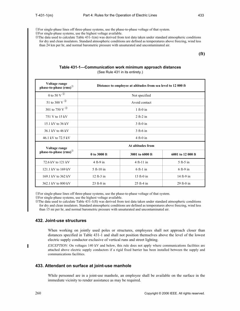
Part 4: Rules for the Operation of Electric LinesT-431-1(m) 433
qFor single-phase lines off three-phase systems, use the phase-to-phase voltage of that system.wFor single-phase systems, use the highest voltage available.eThe data used to calculate Table 431-1(m) was derived from test data taken under standard atmospheric conditions
for dry and clean insulators. Standard atmospheric conditions are defined as temperatures above freezing, wind lessthan 24 km per hr, and normal barometric pressure with unsaturated and uncontaminated air.
(ft)
qFor single-phase lines off three-phase systems, use the phase-to-phase voltage of that system.wFor single-phase systems, use the highest voltage available.eThe data used to calculate Table 431-1(ft) was derived from test data taken under standard atmospheric conditions
for dry and clean insulators. Standard atmospheric conditions are defined as temperatures above freezing, wind lessthan 15 mi per hr, and normal barometric pressure with unsaturated and uncontaminated air.
432. Joint-use structures
When working on jointly used poles or structures, employees shall not approach closer thandistances specified in Table 431-1 and shall not position themselves above the level of the lowestelectric supply conductor exclusive of vertical runs and street lighting.
EXCEPTION: On voltages 140 kV and below, this rule does not apply where communications facilities areattached above electric supply conductors if a rigid fixed barrier has been installed between the supply andcommunications facilities.
433. Attendant on surface at joint-use manhole
While personnel are in a joint-use manhole, an employee shall be available on the surface in theimmediate vicinity to render assistance as may be required.
Table 431-1—Communication work minimum approach distances (See Rule 431 in its entirety.)
Voltage rangephase-to-phase (rms)q Distance to employee at altitudes from sea level to 12 000 ft
0 to 50 V w Not specified
51 to 300 V w Avoid contact
301 to 750 V w 1 ft-0 in
751 V to 15 kV 2 ft-2 in
15.1 kV to 36 kV 3 ft-0 in
36.1 kV to 46 kV 3 ft-6 in
46.1 kV to 72.5 kV 4 ft-0 in
Voltage rangephase-to-phase (rms)q
At altitudes from
0 to 3000 ft 3001 to 6000 ft 6001 to 12 000 ft
72.6 kV to 121 kV 4 ft-9 in 4 ft-11 in 5 ft-5 in
121.1 kV to 169 kV 5 ft-10 in 6 ft-1 in 6 ft-9 in
169.1 kV to 362 kV 12 ft-3 in 13 ft-0 in 14 ft-9 in
362.1 kV to 800 kV 23 ft-8 in 25 ft-4 in 29 ft-0 in
260 Copyright © 2006 IEEE. All rights reserved.
Part 4: Rules for the Operation of Electric Lines434 434
434. Sheath continuity
Metallic or semiconductive sheath continuity shall be maintained by bonding across the opening, orby equivalent means, when working on buried cable or on cable in manholes.
Copyright © 2006 IEEE. All rights reserved. 261

Part 4: Rules for the Operation of Electric Lines440 441A3b(2)
Section 44.Additional rules for supply employees
440. General
Supply employees shall observe the following rules in addition to the rules contained in Section 42.
441. Energized conductors or parts
Employees shall not approach, or knowingly permit others to approach, any exposed ungroundedpart normally energized except as permitted by this rule.
A. Minimum approach distance to live parts
1. General
Employees shall not approach or bring any conductive object within the minimum approachdistance listed in Table 441-1 or 441-4 to exposed parts unless one of the following is met:
a. The line or part is de-energized and grounded per Rule 444D.
b. The employee is insulated from the energized line or part. Electrical protective equipmentinsulated for the voltage involved, such as tools, gloves, rubber gloves, or rubber gloveswith sleeves, shall be considered effective insulation for the employee from the energizedpart being worked on.
c. The energized line or part is insulated from the employee and from any other line or part ata different voltage.
d. The employee is performing barehand live-line work according to Rule 446.
2. Precautions for approach—Voltages from 51 V to 300 V
Employees shall not contact exposed energized parts operating at 51 V to 300 V, unless theprovisions of Rule 441A1 are met.
3. Precautions for approach—Voltages from 301 V to 72.5 kV
At voltages from 301 V to 72.5 kV, employees shall be protected from phase-to-phase andphase-to-ground differences in voltage. See Table 441-1 for the minimum approach distancesto live parts.
a. When exposed grounded lines, conductors, or parts are in the work area, they shall beguarded or insulated.
b. When the Rubber Glove Work Method is employed, rubber insulating gloves, insulatedfor the maximum use voltage as listed in Table 441-6, shall be worn whenever employeesare within the reach or extended reach of the minimum approach distances listed in Table441-1, supplemented by one of the following two protective methods:
(1) The employee shall wear rubber insulating sleeves, insulated for the maximum usevoltage as listed in Table 441-6, in addition to the rubber insulating gloves.
EXCEPTION: When work is performed on electric supply equipment energized at 750 V orless, rubber sleeves are not required if only the live parts being worked on are exposed.
(2) All exposed energized lines or parts, other than those temporarily exposed to performwork and maintained under positive control, located within maximum reach of theemployee’s work position, shall be covered with insulating protective equipment.
EXCEPTION: When work is being performed on parts energized between 300 V and 750 Vwithin enclosed spaces, (e.g., control panels and relay cabinets), insulating or guarding of allexposed grounded lines, conductors, or parts in the work area is not required provided thatemployees use insulated tools and/or gloves and that exposed grounded lines, conductors, orparts are covered to the extent feasible.
262 Copyright © 2006 IEEE. All rights reserved.
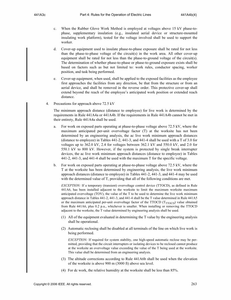
Part 4: Rules for the Operation of Electric Lines441A3c 441A4b(4)
c. When the Rubber Glove Work Method is employed at voltages above 15 kV phase-to-phase, supplementary insulation (e.g., insulated aerial device or structure-mountedinsulating work platform), tested for the voltage involved shall be used to support theworker.
d. Cover-up equipment used to insulate phase-to-phase exposure shall be rated for not lessthan the phase-to-phase voltage of the circuit(s) in the work area. All other cover-upequipment shall be rated for not less than the phase-to-ground voltage of the circuit(s).The determination of whether phase-to-phase or phase-to-ground exposure exists shall bebased on factors such as but not limited to: work rules, conductor spacing, workerposition, and task being performed.
e. Cover-up equipment, when used, shall be applied to the exposed facilities as the employeefirst approaches the facilities from any direction, be that from the structure or from anaerial device, and shall be removed in the reverse order. This protective cover-up shallextend beyond the reach of the employee’s anticipated work position or extended reachdistance.
4. Precautions for approach above 72.5 kV
The minimum approach distance (distance to employee) for live work is determined by therequirements in Rule 441A4a or 441A4b. If the requirements in Rule 441A4b cannot be met intheir entirety, Rule 441A4a shall be used.
a. For work on exposed parts operating at phase-to-phase voltage above 72.5 kV, where themaximum anticipated per-unit overvoltage factor (T) at the worksite has not beendetermined by an engineering analysis, the ac live work minimum approach distances(distance to employee) in Tables 441-2, 441-3, and 441-4 shall be used with a T of 3.0 forvoltages up to 362.0 kV, 2.4 for voltages between 362.1 kV and 550.0 kV, and 2.0 for550.1 kV to 800 kV. However, if the system is protected by single break interrupterdevices, the ac live work minimum approach distances (distance to employee) in Tables441-2, 441-3, and 441-4 shall be used with the maximum T for the specific voltage.
b. For work on exposed parts operating at phase-to-phase voltage above 72.5 kV, where theT at the worksite has been determined by engineering analysis, the live work minimumapproach distances (distance to employee) in Tables 441-2, 441-3, and 441-4 may be usedwith the determined value of T, providing that all of the following conditions are met.
EXCEPTION: If a temporary (transient) overvoltage control device (TTOCD), as defined in Rule441A6, has been installed adjacent to the worksite to limit the maximum worksite maximumanticipated overvoltage (TOV), the value of the T to be used to determine the live work minimumapproach distance in Tables 441-2, 441-3, and 441-4 shall be the T value determined in Rule 441A5or the maximum anticipated per-unit overvoltage factor of the TTOCD (TTTOCD) value obtainedfrom Rule 441A6, plus 0.2 p.u., whichever is smaller. When installing or removing the TTOCDadjacent to the worksite, the T value determined by engineering analysis shall be used.
(1) All of the equipment evaluated in determining the T value by the engineering analysisshall be operational.
(2) Automatic reclosing shall be disabled at all terminals of the line on which live work isbeing performed.
EXCEPTION: If required for system stability, one high-speed automatic reclose may be per-mitted, providing that the circuit interrupters or isolating devices to be reclosed cannot produceat the worksite an overvoltage value exceeding the value of the T being used at the worksite.This value shall be determined from an engineering analysis.
(3) The altitude corrections according to Rule 441A6b shall be used when the elevationof the worksite is above 900 m (3000 ft) above sea level.
(4) For dc work, the relative humidity at the worksite shall be less than 85%.
Copyright © 2006 IEEE. All rights reserved. 263
Part 4: Rules for the Operation of Electric Lines441A5 441B3
5. Temporary (transient) overvoltage control device (TTOCD)
TTOCD, which are designed and tested for installation adjacent to the worksite to limit theTOV at the worksite, may be used to obtain a lower value of T.
An engineering analysis, including laboratory testing, of the TTOCD shall be performed todetermine and identify the range of sparkover voltages. The withstand and sparkover character-istics of a TTOCD are determined by sparkover probability data for the particular protectivegap geometry, gap distance, and conductor bundle geometry. The TOV rating for the TTOCDdevice shall be determined from test data and shall be the voltage at which the device sparksover 50% of the time. The TTTOCD is calculated by dividing the TOV rating of the device bynominal peak voltage rounded-up to one decimal place.
As an example of determining TTTOCD, for a line operating at 345 kV, using TTOCD whichhas been installed adjacent to the worksite to limit the maximum worksite TTTOCD, having aTOV rating of 510 kV:
TTTOCD = 510 / ((362 ⋅ 1.414) / 1.732)
TTTOCD = 510 / 295.53 = 1.72 or 1.8
6. Altitude correction
The distances in Tables 441-2, 441-3, and 441-4 shall be used at elevations below 900 m(3000 ft). Above that altitude, the minimum approach distance shall be increased by:
a. Multiplying the electrical component of the minimum approach distance by the applicablealtitude correction factors of Table 441-5, and
b. Adding the result to the values for inadvertent movement required by Rule 441A7a.
NOTE: The electrical component of clearance included in Tables 441-2, 441-3, and 441-4 is thetable value less the value for inadvertent movement for that voltage shown in Rule 441A7a.
7. Determining the minimum approach distances (distances to employee)
a. Minimum approach distances calculated under this rule for 0.301 kV to 0.750 kV containthe electrical component plus 0.30 m (1 ft) for inadvertent movement. Voltages 0.751 kVto 72.5 kV contain the electrical component plus 0.61 m (2 ft) for inadvertent movement.Above 72.5 kV, the inadvertent movement distance is 0.31 m (1 ft).
b. Data for minimum approach distances between 1.1 and 72.5 kV shown in Table 441-1 wasobtained from rod gap data measured in metric units; the values in Table 441-1 are derivedfrom metric and converted to feet and inches.
c. Data for minimum approach distances above 72.5 kV shown in Tables 441-2, 441-3, and441-4 was taken from IEEE Std 516-2003. In IEEE Std 516-2003, the customary unittables are calculated in feet to two decimal places. The second decimal place is rounded upif the third decimal place is other than zero. The metric tables were calculated from the fttables and rounded up to two decimal places, using a conversion factor of 0.3048 m per ft.For this reason, the customary-unit tables do not exactly convert into the values shown inthe metric tables.
d. The voltage ranges are contained in ANSI C84.1-1995, Table 1.
B. Additional approach requirements
1. The clear insulation distance associated with insulators shall be the shortest straight-line air-gap distance from the nearest energized part to the nearest grounded part.
2. When working on insulators under live work procedures employing rubber gloves or live-linetools, the clear insulation distance shall be not less than the straight-line distance in air requiredby Rule 441A4.
3. Work may be performed at the grounded end of an open switch if all of the followingconditions are met:
264 Copyright © 2006 IEEE. All rights reserved.

Part 4: Rules for the Operation of Electric Lines441B3a 441C2
a. The air-gap distance of the switch shall not be reduced in any manner. This distance shallbe not less than the minimum approach distances determined by Rules 441A2, 441A3, and441A4 less the inadvertent movement values. The inadvertent movement values of Rule441A7(a) are not required in this distance.
b. The minimum approach distance to the energized part of the switch shall be not less thanthat required by Rules 441A2, 441A3, and 441A4.
4. Special rules for working on insulator assemblies operating above 72.5 kV
a. When work is to be performed at the ground end of an insulator assembly, the minimumapproach distance to the nearest energized part may equal the straight-line distance mea-sured along the insulators.
b. For suspension insulator assembly installations (see ANSI C29.2-1992) operating above72.5 kV (ac), the first insulator at the grounded end may be temporarily shorted out as partof the work procedure. Before temporarily shorting out any insulator units, as part of thework procedure, each of the insulator units in the string shall be tested to determine thenumber and location of any failed units.
EXCEPTION: For voltages at 230 kV (ac) and above, up to three insulator units may be temporarilyshorted out as part of the work procedure, provided that the minimum approach distance require-ments of Rule 441A4 are met.
c. When performing live work employing the barehand technique on installations operatingabove 72.5 kV (ac), the first insulator at the energized (hot) end of a suspension insulatorassembly (see ANSI C29.2-1992) may be shorted out during the work. Before temporarilyshorting out any insulator units, as part of the work procedure, each of the insulator unitsin the string shall be tested to determine the number and location of any failed units.
EXCEPTION: For voltages at 230 kV (ac) and above, up to three insulator units may be temporarilyshorted out as part of the work procedure, provided that the minimum approach distance require-ments of Rule 441A4 are met.
(1) The minimum approach distance to the grounded end of the insulator assembly maybe equal to the straight-line distance from the nearest energized part to the closestgrounded part across the insulators.
(2) The straight-line insulation distance shall be not less than the values required by Rule441A4.
C. Live-line tool clear insulation length
1. Clear live-line tool length
The clear live-line tool distance shall be not less than the distance measured longitudinallyalong the live-line tool from the conductive part at the working end of the tool and any part ofthe employee. Distances for conducting sections (such as metallic splices and hardware) shallbe subtracted from the clear live-line length. The clear live-line tool length shall equal orexceed the values for the minimum approach distance in Tables 441-1, 441-2, 441-3, and 441-4for the indicated voltage ranges. The minimum clear live-line tool distance shall be the distancemeasured longitudinally along the live-line tool from the conductive part at the working end ofthe tool to any part of the employee.
2. Live-line conductor support tool length
Conductor support tools such as link sticks, strain carriers, and insulator cradles may be usedprovided that the clear insulating distance is at least as long as the insulator string or the maxi-mum distance specified in Rule 441A4. When installing this equipment, the employee shallmaintain the minimum approach distance required equal to the clear insulating length for thesupport tools.
NOTE: Conductive components of tools disturb the field in the gap and decrease the insulation value ofthe tool more than the linear subtraction of the length(s) of the conductive components.
Copyright © 2006 IEEE. All rights reserved. 265
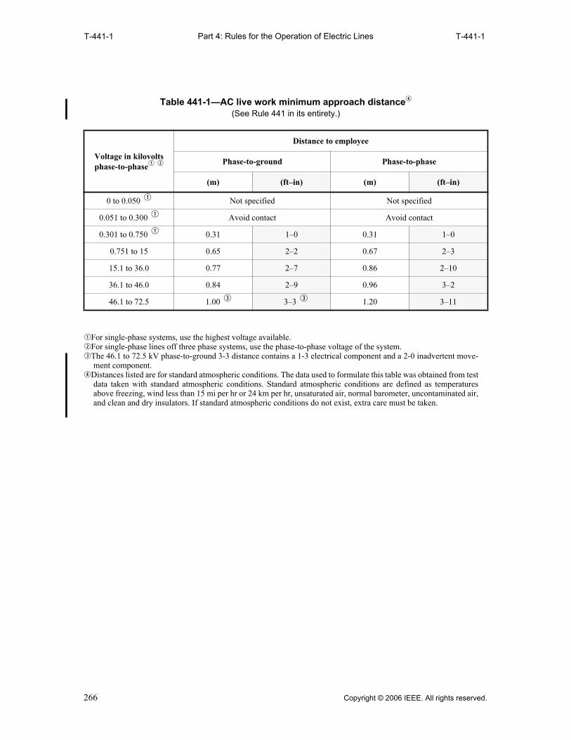
Part 4: Rules for the Operation of Electric LinesT-441-1 T-441-1
qFor single-phase systems, use the highest voltage available.wFor single-phase lines off three phase systems, use the phase-to-phase voltage of the system.eThe 46.1 to 72.5 kV phase-to-ground 3-3 distance contains a 1-3 electrical component and a 2-0 inadvertent move-
ment component.rDistances listed are for standard atmospheric conditions. The data used to formulate this table was obtained from test
data taken with standard atmospheric conditions. Standard atmospheric conditions are defined as temperaturesabove freezing, wind less than 15 mi per hr or 24 km per hr, unsaturated air, normal barometer, uncontaminated air,and clean and dry insulators. If standard atmospheric conditions do not exist, extra care must be taken.
Table 441-1—AC live work minimum approach distancer
(See Rule 441 in its entirety.)
Voltage in kilovolts phase-to-phaseq w
Distance to employee
Phase-to-ground Phase-to-phase
(m) (ft–in) (m) (ft–in)
0 to 0.050 q Not specified Not specified
0.051 to 0.300 q Avoid contact Avoid contact
0.301 to 0.750 q 0.31 1–0 0.31 1–0
0.751 to 15 0.65 2–2 0.67 2–3
15.1 to 36.0 0.77 2–7 0.86 2–10
36.1 to 46.0 0.84 2–9 0.96 3–2
46.1 to 72.5 1.00 e 3–3 e 1.20 3–11
266 Copyright © 2006 IEEE. All rights reserved.

Part 4: Rules for the Operation of Electric LinesT-441-2(m) T-441-2(m)
m
qDistances listed are for standard atmospheric conditions. The data used to formulate this table was obtained from testdata taken with standard atmospheric conditions. Standard atmospheric conditions are defined as temperaturesabove freezing, wind less than 24 km per hr, unsaturated air, normal barometer, uncontaminated air, and clean anddry insulators. If standard atmospheric conditions do not exist, extra care must be taken.
wDistances are based on altitudes below 900 m above sea level. For altitudes above 900 m, Rule 441A6 applies.
eSee Rule 441A4a.
Table 441-2—AC live work minimum approach distances for altitudes less than 900 mabove sea level, where T has been determined according to Rule 441A5q w
(See Rule 441 in its entirety.)
Maximum anticipated
per unit overvoltage
factorT
Distance to employee—phase-to-ground work, in air, barehand, and clear live-line tool
Maximum phase-to-phase voltage in kV
72.5 to 121.0
121.1 to 145.0
145.1 to 169.0
169.1 to 242.0
242.1 to 362.0
362.1 to 550.0
550.1 to 800.0
1.5 0.72 0.73 0.80 1.01 1.36 1.96 3.16
1.6 0.79 0.76 0.83 1.05 1.43 2.12 3.46
1.7 0.86 0.78 0.86 1.10 1.50 2.28 3.78
1.8 0.93 0.81 0.90 1.15 1.57 2.45 4.11
1.9 1.01 0.84 0.93 1.20 1.64 2.62 4.45
2.0 1.07 0.87 0.96 1.24 1.71 2.82 4.84 e
2.1 1.10 0.90 0.99 1.29 1.78 3.01 5.22
2.2 1.12 0.92 1.03 1.34 1.88 3.20 5.60
2.3 1.14 0.95 1.06 1.38 1.98 3.40 6.00
2.4 1.16 0.98 1.09 1.43 2.08 3.61 e 6.46
2.5 1.18 1.01 1.12 1.48 2.19 3.84 6.89
2.6 1.20 1.04 1.16 1.52 2.30 4.06
2.7 1.23 1.06 1.19 1.57 2.41 4.30
2.8 1.25 1.09 1.22 1.62 2.54 4.56
2.9 1.27 1.12 1.26 1.66 2.65 4.80
3.0 e 1.29 1.15 1.29 1.71 2.77 5.07
3.1 1.31 1.18 1.32 1.76 2.89
3.2 1.33 1.20 1.35 1.82 3.02
3.3 1.36 1.23 1.39 1.88 3.15
3.4 1.37 1.26 1.42 1.94 3.27
3.5 1.39 1.29 1.45 2.02 3.40
Copyright © 2006 IEEE. All rights reserved. 267
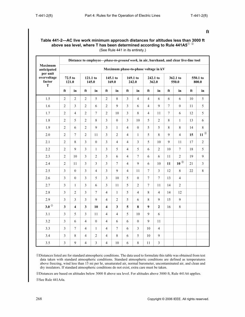
Part 4: Rules for the Operation of Electric LinesT-441-2(ft) T-441-2(ft)
ft
qDistances listed are for standard atmospheric conditions. The data used to formulate this table was obtained from testdata taken with standard atmospheric conditions. Standard atmospheric conditions are defined as temperaturesabove freezing, wind less than 15 mi per hr, unsaturated air, normal barometer, uncontaminated air, and clean anddry insulators. If standard atmospheric conditions do not exist, extra care must be taken.
wDistances are based on altitudes below 3000 ft above sea level. For altitudes above 3000 ft, Rule 441A6 applies.
eSee Rule 441A4a.
Table 441-2—AC live work minimum approach distances for altitudes less than 3000 ft above sea level, where T has been determined according to Rule 441A5q w
(See Rule 441 in its entirety.)
Maximum anticipated
per unit overvoltage
factorT
Distance to employee—phase-to-ground work, in air, barehand, and clear live-line tool
Maximum phase-to-phase voltage in kV
72.5 to 121.0
121.1 to 145.0
145.1 to 169.0
169.1 to 242.0
242.1 to 362.0
362.1 to 550.0
550.1 to800.0
ft in ft in ft in ft in ft in ft in ft in
1.5 2 2 2 5 2 8 3 4 4 6 6 6 10 5
1.6 2 3 2 6 2 9 3 6 4 9 7 0 11 5
1.7 2 4 2 7 2 10 3 8 4 11 7 6 12 5
1.8 2 5 2 8 3 0 3 10 5 2 8 1 13 6
1.9 2 6 2 9 3 1 4 0 5 5 8 8 14 8
2.0 2 7 2 11 3 2 4 1 5 8 9 4 15 11 e
2.1 2 8 3 0 3 4 4 3 5 10 9 11 17 2
2.2 2 9 3 1 3 5 4 5 6 2 10 7 18 5
2.3 2 10 3 2 3 6 4 7 6 6 11 2 19 9
2.4 2 11 3 3 3 7 4 9 6 10 11 10 e 21 3
2.5 3 0 3 4 3 9 4 11 7 3 12 8 22 8
2.6 3 0 3 5 3 10 5 0 7 7 13 4
2.7 3 1 3 6 3 11 5 2 7 11 14 2
2.8 3 2 3 7 4 1 5 4 8 4 14 12
2.9 3 3 3 9 4 2 5 6 8 9 15 9
3.0 e 3 4 3 10 4 3 5 8 9 2 16 8
3.1 3 5 3 11 4 4 5 10 9 6
3.2 3 6 4 0 4 6 6 0 9 11
3.3 3 7 4 1 4 7 6 3 10 4
3.4 3 8 4 2 4 8 6 5 10 9
3.5 3 9 4 3 4 10 6 8 11 3
268 Copyright © 2006 IEEE. All rights reserved.

Part 4: Rules for the Operation of Electric LinesT-441-3(m) T-441-3(m)
m
qDistances listed are for standard atmospheric conditions. The data used to formulate this table was obtained from testdata taken with standard atmospheric conditions. Standard atmospheric conditions are defined as temperaturesabove freezing, wind less than 24 km per hr, unsaturated air, normal barometer, uncontaminated air, and clean anddry insulators. If standard atmospheric conditions do not exist, extra care must be taken.
wDistances are based on altitudes below 900 m above sea level. For altitudes above 900 m, Rule 441A6 applies. eSee Rule 441A4a.
Table 441-3—AC live work minimum approach distances for altitudes less than 900 m above sea level, where the T has been determined according to Rule 441A5q w
(See Rule 441 in its entirety.)
Maximum anticipated
per unit overvoltage
factorT
Distance to employee—phase-to-phase work, in air, barehand, and clear live-line tool
Maximum phase-to-phase voltage in kV
72.5 to 121.0
121.1 to 145.0
145.1 to 169.0
169.1 to 242.0
242.1 to 362.0
362.1 to 550.0
550.1 to 800.0
1.5 0.76 0.85 0.94 1.21 1.65 2.43 3.96
1.6 0.84 0.94 1.05 1.36 1.89 2.86 4.76
1.7 0.92 1.04 1.16 1.53 2.13 3.33 5.62
1.8 1.00 1.13 1.27 1.68 2.36 3.80 6.51
1.9 1.08 1.23 1.38 1.85 2.61 4.32 7.48
2.0 1.15 1.32 1.48 2.00 2.83 4.84 8.47 e
2.1 1.18 1.35 1.53 2.05 2.91 5.09 9.00
2.2 1.20 1.38 1.56 2.09 3.03 5.32 9.47
2.3 1.22 1.41 1.59 2.14 3.15 5.57 9.99
2.4 1.25 1.44 1.62 2.19 3.27 5.82 e 10.58
2.5 1.27 1.46 1.65 2.23 3.39 6.11 11.10
2.6 1.29 1.49 1.69 2.28 3.53 6.39
2.7 1.32 1.52 1.72 2.33 3.67 6.71
2.8 1.35 1.55 1.76 2.38 3.83 7.03
2.9 1.37 1.58 1.79 2.43 3.97 7.32
3.0 e 1.39 1.61 1.82 2.48 4.10 4.64
3.1 1.41 1.63 1.85 2.52 4.24
3.2 1.43 1.66 1.88 2.58 4.37
3.3 1.46 1.69 1.92 2.66 4.54
3.4 1.48 1.71 1.94 2.71 4.67
3.5 1.50 1.73 1.97 2.80 4.80
Copyright © 2006 IEEE. All rights reserved. 269

Part 4: Rules for the Operation of Electric LinesT-441-3(ft) T-441-3(ft)
ft
qDistances listed are for standard atmospheric conditions. The data used to formulate this table was obtained from testdata taken with standard atmospheric conditions. Standard atmospheric conditions are defined as temperaturesabove freezing, wind less than 15 mi per hr, unsaturated air, normal barometer, uncontaminated air, and clean anddry insulators. If standard atmospheric conditions do not exist, extra care must be taken.
wDistances are based on altitudes below 3000 ft above sea level. For altitudes above 3000 ft, Rule 441A6 applies. eSee Rule 441A4a.
Table 441-3—AC live work minimum approach distances for altitudes less than 3000 ft above sea level, where T has been determined according to Rule 441A5q w
(See Rule 441 in its entirety.)
Maximum anticipated
per unit overvoltage
factorT
Distance to employee—phase-to-phase work, in air, barehand, and clear live-line tool
Maximum phase-to-phase voltage in kV
72.5 to 121.0
121.1 to 145.0
145.1 to 169.0
169.1 to 242.0
242.1 to 362.0
362.1 to 550.0
550.1 to800.0
ft in ft in ft in ft in ft in ft in ft in
1.5 2 6 2 10 3 1 4 0 5 6 8 0 13 0
1.6 2 9 3 2 3 6 4 6 6 3 9 5 15 8
1.7 3 1 3 5 3 10 5 1 7 0 11 0 18 6
1.8 3 4 3 9 4 3 5 7 7 9 12 6 21 5
1.9 3 7 4 1 4 7 6 1 8 7 14 3 24 7
2.0 3 10 4 4 4 11 6 7 9 4 15 11 27 10 e
2.1 3 11 4 6 5 1 6 9 9 7 16 9 29 7
2.2 4 0 4 7 5 2 6 11 10 0 17 6 31 1
2.3 4 1 4 8 5 3 7 1 10 5 18 4 32 10
2.4 4 2 4 9 5 4 7 3 10 9 19 2 e 34 9
2.5 4 3 4 10 5 6 7 4 11 2 20 1 36 6
2.6 4 3 4 11 5 7 7 6 11 7 21 0
2.7 4 4 5 0 5 8 7 8 12 1 22 0
2.8 4 6 5 1 5 10 7 10 12 7 23 1
2.9 4 6 5 3 5 11 8 0 13 1 24 0
3.0 e 4 7 5 4 6 0 8 2 13 6 25 1
3.1 4 8 5 5 6 1 8 4 13 11
3.2 4 9 5 6 6 2 8 6 14 5
3.3 4 10 5 7 6 4 8 9 14 11
3.4 4 11 5 8 6 5 8 11 15 4
3.5 5 0 5 9 6 6 9 3 15 9
270 Copyright © 2006 IEEE. All rights reserved.

Part 4: Rules for the Operation of Electric LinesT-441-4(m) T-441-4(ft)
m
ft
NOTES for Table 441-4 (m and ft)1. When the value of T at the worksite has not been determined according to Rule 441A5, T = 1.8 shall be used. 2. The data used to calculate these tables was obtained from test data taken with standard atmospheric conditions.
Standard atmospheric conditions are defined as temperatures above freezing, wind less than 15 mi per hr or 24 kmper hr, unsaturated air, normal barometer, uncontaminated air, and clean and dry insulators. If standard atmosphericconditions do not exist, extra care must be taken.
3. For altitudes above 3000 ft or 900 m, Rule 441A6 applies.
Table 441-4—DC live work minimum approach distance for altitudes less than 900 m above sea level
(See Rule 441 in its entirety.)
Maximum anticipated per unit overvoltage
factorT
Distance to employee—pole-to-ground, air, barehand, clear live-line tool
Maximum pole-to-pole voltage in kV
0 to 250 251 to 400 401 to 500 501 to 600 601 to 750
1.5 or lower 1.12 1.60 2.06 2.62 3.61
1.6 1.17 1.69 2.24 2.86 3.98
1.7 1.23 1.82 2.42 3.12 4.37
1.8 1.28 1.95 2.62 3.39 4.79
Table 441-4—DC Live work minimum approach distance for altitudes less than 3000 ft above sea level
(See Rule 441 in its entirety.)
Maximum anticipated
per unit overvoltage
factorT
Distance to employee—pole-to-ground, air, barehand, clear live-line tool
Maximum pole-to-pole voltage in kV
0 to 250 251 to 400 401 to 500 501 to 600 601 to 750
ft in ft in ft in ft in ft in
1.5 or lower 3 8 5 3 6 9 8 7 11 10
1.6 3 10 5 7 7 4 9 5 13 1
1.7 4 1 6 0 7 11 10 3 14 4
1.8 4 3 6 5 8 7 11 2 15 9
Copyright © 2006 IEEE. All rights reserved. 271

Part 4: Rules for the Operation of Electric LinesT-441-5 T-441-6
qThe maximum use voltage is the ac voltage (rms) rating of the protective equipment that designates the maximumnominal design voltage of the energized system that may be safely worked. The nominal design voltage is equal tothe phase-to-phase voltage on multiphase circuits.
EXCEPTION 1: If there is no multiphase exposure in a system area (at the worksite) and the voltage exposure islimited to the phase (polarity on dc systems) to ground potential, the phase (polarity on dc systems) to groundpotential shall be considered to be the nominal design voltage.EXCEPTION 2: If electric equipment and devices are insulated, isolated, or both, such that the multiphase exposureon a grounded wye circuit is removed and if supplemental insulation (e.g., insulated aerial device or structure-mounted insulating work platform) is used to insulate the employee from ground, then the nominal design voltagemay be considered as the phase-to-ground voltage on that circuit.
Table 441-5—Altitude correction factor (See Rule 441 in its entirety.)
AltitudeCorrection factor
(m) (ft)
Sea level to 900 Sea level to 3,000 1.00
901 to 1,200 3001 to 4000 1.02
1201 to 1500 4001 to 5000 1.05
1501 to 1800 5001 to 6000 1.08
1801 to 2100 6001 to 7000 1.11
2101 to 2400 7001 to 8000 1.14
2401 to 2700 8001 to 9000 1.17
2701 to 3000 9001 to 10 000 1.20
3001 to 3600 10 001 to 12 000 1.25
3601 to 4200 12 001 to 14 000 1.30
Table 441-6—Maximum use voltage for rubber insulating equipment
Class of equipment Maximum use voltageq
00 500
0 1000
1 7500
2 17 000
3 26 500
4 36 000
272 Copyright © 2006 IEEE. All rights reserved.

Part 4: Rules for the Operation of Electric Lines442 442E2
442. Switching control procedures
A. Designated person
A designated person shall:
1. Keep informed of operating conditions affecting the safe and reliable operation of the system.
2. Maintain a suitable record showing operating changes in such conditions.
3. Issue or deny authorization for switching, as required, for safe and reliable operation.
B. Specific work
Authorization from the designated person shall be secured before work is begun on or in the vicinityof station equipment, transmission, or interconnected feeder circuits and where circuits are to be de-energized at stations. The designated person shall be notified when such work ceases.EXCEPTION 1: In an emergency, to protect life or property, or when communication with the designatedperson is difficult because of storms or other causes, any qualified employee may make repairs on or in thevicinity of the equipment or lines covered by this rule without special authorization if the qualified employeecan clear the trouble promptly with available help in compliance with the remaining rules. The designatedperson shall thereafter be notified as soon as possible of the action taken.
EXCEPTION 2: Suspension of normal rule or rules under disaster conditions: Where catastrophic servicedisruptions occur (e.g., earthquake, hurricane) and where multiple employer crews may be imported to assist inservice restorations, the normal use of Rule 442 procedures may be suspended provided that:
(a) Each individual involved in system repairs is informed of the suspension of normal rules.
(b) Employees are required to observe all requirements of Rules 443 and 444, including protection designatedfrom step and touch potentials.
(c) Equipment used to de-energize or re-energize circuits at designated points of control (e.g., stationbreakers) is operated in conformance with Rules 442A and 442D.
(d) Tagging requirements under Rule 444C, for this EXCEPTION, shall include, and may be limited to,designated points of control.
C. Operations at stations
Qualified employees shall obtain authorization from the designated person before switching sectionsof circuits.
In the absence of specific operating schedules, employees shall secure authorization from thedesignated person before opening and closing supply circuits or portions thereof or starting andstopping equipment affecting system operation at stations.
EXCEPTION 1: Sections of distribution circuits are excepted if the designated person is notified as soon aspossible after the action is taken.
EXCEPTION 2: In an emergency, to protect life or property, any qualified employee may open circuits and stopmoving equipment without special authorization if, in the judgment of the qualified employee, this action willpromote safety, but the designated person shall be notified as soon as possible of such action, with reasonstherefore.
D. Re-energizing after work
Instructions to re-energize equipment or lines that have been de-energized by permission of thedesignated person shall not be issued by the designated person until all employees who requested theline to be de-energized have reported clear. Employees who have requested equipment or lines de-energized for other employees or crews shall not request that equipment or lines be re-energizeduntil all of the other employees or crews have reported clear. The same procedure shall be followedwhen more than one location is involved.
E. Tagging electric supply circuits associated with work activities
1. Equipment or circuits that are to be treated as de-energized and grounded per Rule 444D shallhave suitable tags attached to all points where such equipment or circuits can be energized.
2. When the automatic reclosing feature of a reclosing device is disabled during the course ofwork on energized equipment or circuits, a tag shall be placed at the reclosing device location.
Copyright © 2006 IEEE. All rights reserved. 273
Part 4: Rules for the Operation of Electric Lines442E3 443A4c
EXCEPTION: If the automatic reclosing feature of a reclosing device is disabled by a Supervisory Con-trol and Data Acquisition System (SCADA), the system shall provide for the following:
(a) At the SCADA operating point
(1) A signal is received by the SCADA operator confirming that the disabling operation has occurredat the reclosing device location, and
(2) A readily visible tag or electronic display is used to inform any potential SCADA operator that adisabling operation has been initiated, and
(3) The tag or electronic display is removed before action is taken to re-enable the automatic reclosingfeature.
(b) At the reclosing device location
(1) The reclosing feature is disabled in such a manner as to prevent manual override of the normal con-trol by any potential on-site operator, or
(2) A signal, flag, or other display is used in such a manner as to alert any potential on-site operatorthat the reclosing feature has been disabled.
3. The required tags shall be placed to clearly identify the equipment or circuits on which work isbeing performed.
F. Restoration of service after automatic trip
1. When circuits or equipment upon which tags have been placed open automatically, the circuitsor equipment shall be left open until reclosing has been authorized.
2. When circuits open automatically, local operating rules shall determine in what manner andhow many times they may be closed with safety.
G. Repeating oral messages
Each employee receiving an oral message concerning the switching of lines and equipment shallimmediately repeat it back to the sender and obtain the identity of the sender. Each employeesending such an oral message shall require it to be repeated back by the receiver and secure thelatter’s identity.
443. Work on energized lines and equipment
A. General requirements
1. When working on energized lines and equipment, one of the following safeguards shall beapplied:
a. Insulate employee from energized parts
b. Isolate or insulate the employee from ground and grounded structures, and potentials otherthan the one being worked on
2. Employees shall not place dependence for their safety on the covering (nonrated insulation) ofwires. All precautions (see Section 44) for working on energized parts shall be observed.
3. All employees working on or in the vicinity of lines or equipment exposed to voltages higherthan those guarded against by the safety protective equipment provided shall assure themselvesthat the equipment or lines on which they are working are free from dangerous leakage orinduction, or have been effectively grounded.
4. Cutting into insulating coverings of energized conductors
a. A supply cable to be worked on as de-energized that cannot be positively identified ordetermined to be de-energized shall be pierced or severed at the work location with a tooldesigned for the purpose.
b. Before cutting into an energized supply cable, the operating voltage shall be determinedand appropriate precautions taken for handling conductors at that voltage.
c. When the insulating covering on energized wires or cables must be cut into, the employeeshall use a tool designed for the purpose. While doing such work, suitable eye protection
274 Copyright © 2006 IEEE. All rights reserved.
Part 4: Rules for the Operation of Electric Lines443A5 443I
and insulating gloves with protectors shall be worn. Employees shall exercise extremecare to prevent short-circuiting conductors when cutting into the insulation.
5. Metal measuring tapes, and tapes or ropes containing metal threads or strands, shall not be usedcloser to exposed energized parts than the distance specified in Rule 441A. Care should betaken when extending metallic ropes or tapes parallel to and in the proximity of high-voltagelines because of the effect of induced voltages.
6. Equipment or material of a noninsulating substance that is not bonded to an effective groundand which extends into an energized area, and which could approach energized equipmentcloser than the distance specified in Rule 441A, shall be treated as though it is energized at thesame voltage as the line or equipment to which it is exposed.
B. Requirement for assisting employee
In inclement weather or at night, no employee shall work alone outdoors on or dangerously in thevicinity of energized conductors or parts of more than 750 V between conductors.
EXCEPTION: This shall not preclude a qualified employee, working alone, from cutting trouble in the clear,switching, replacing fuses, or similar work if such work can be performed safely.
C. Opening and closing switches
Manual switches and disconnectors shall always be closed by a continuous motion. Care should beexercised in opening switches to avoid serious arcing.
D. Working position
Employees should avoid working on equipment or lines in any position from which a shock or slipwill tend to bring the body toward exposed parts at a potential different than the employee’s body.Work should, therefore, generally be done from below, rather than from above.
E. Protecting employees by switches and disconnectors
When equipment or lines are to be disconnected from any source of electric energy for theprotection of employees, the switches, circuit breakers, or other devices designated and designed foroperation under the load involved at sectionalizing points shall be opened or disconnected first.When re-energizing, the procedure shall be reversed.
F. Making connections
In connecting de-energized equipment or lines to an energized circuit by means of a conducting wireor device, employees should first attach the wire to the de-energized part. When disconnecting, thesource end should be removed first. Loose conductors should be kept away from exposed energizedparts.
G. Switchgear
Switchgear shall be de-energized and grounded per Rule 444D prior to performing work involvingremoval of protective barriers unless other suitable means are provided for employee protection. Thepersonnel safety features in switchgear shall be replaced after work is completed.
H. Current transformer secondaries
The secondary of a current transformer shall not be opened while energized. If the entire circuitcannot be properly de-energized before working on an instrument, a relay, or other section of acurrent transformer secondary circuit, the employee shall bridge the circuit with jumpers so that thecurrent transformer secondary will not be opened.
I. Capacitors
Before employees work on capacitors, the capacitors shall be disconnected from the energizingsource, short-circuited, and grounded. Any line to which capacitors are connected shall be short-circuited and grounded before it is considered de-energized. Since capacitor units may be connectedin series-parallel, each unit shall be shorted between all insulated terminals and the capacitor tankbefore handling. Where the tanks of capacitors are on ungrounded racks, the racks shall also begrounded. The internal resistor shall not be depended upon to discharge capacitors.
Copyright © 2006 IEEE. All rights reserved. 275
Part 4: Rules for the Operation of Electric Lines443J 444D
J. Gas-insulated equipment
Employees working on gas-insulated cable systems or circuit breakers shall be instructedconcerning the special precautions required for possible presence of arcing by-products of sulfur-hexafluoride (SF6).
NOTE: By-products resulting from arcing in sulfur-hexafluoride (SF6) gas-insulated systems are generallytoxic and irritant. Gaseous by-products can be removed for maintenance on the compartments by purging withair or dry nitrogen. The solid residue that must be removed is mostly metallic fluoride. This fine powderabsorbs moisture and produces fluorides of sulfur and hydrofluoric acid, which are toxic and corrosive.
K. Attendant on surface
While electric supply personnel are in a manhole, an employee shall be available on the surface inthe immediate vicinity to render assistance from the surface. This shall not preclude the employeeon the surface from entering the manhole to provide short-term assistance.
EXCEPTION: This shall not preclude a qualified employee, working alone, from entering a manhole whereenergized cables or equipment are in service, for the purpose of inspection, housekeeping, taking readings, orsimilar work if such work can be performed safely.
L. Unintentional grounds on delta circuits
Unintentional grounds on delta circuits shall be removed as soon as practical.
444. De-energizing equipment or lines to protect employees
A. Application of rule
1. When employees must depend on others to operate switches or otherwise de-energize circuitson which they are to work, or must secure special authorization before they operate suchswitches themselves, the precautionary measures that follow shall be taken in the order givenbefore work is begun.
2. If the employee under whose direction a section of a circuit is disconnected is in sole charge ofthe section and of the means of disconnection, those portions of the following measures thatpertain to dealing with the designated person may be omitted.
3. Records shall be kept on all contractual utility interactive systems on any electric supply lines.When these lines are de-energized according to Rule 444C, the utility interactive system shallbe visibly disconnected from the lines.
B. Employee’s request
The employee in charge of the work shall apply to the designated person to have the particularsection of equipment or lines de-energized, identifying it by position, letter, color, number, or othermeans.
C. Operating switches, disconnectors, and tagging
The designated person shall direct the operation of all switches and disconnectors through whichelectric energy may be supplied to the particular section of equipment and lines to be de-energized,and shall direct that such switches and disconnectors be rendered inoperable and tagged. If switchesthat are controlled automatically or remotely or both can be rendered inoperable, they shall betagged at the switch location. If it is impractical to render such switches and disconnectorsinoperable, then these remotely controlled switches shall also be tagged at all points of control. Arecord shall be made when placing the tag, giving the time of disconnection, the name of the personmaking the disconnection, the name of the employee who requested the disconnection, and the nameor title or both, of the designated person.
D. Employee’s protective grounds
When all the switches and disconnectors designated have been operated, rendered inoperable wherepractical, and tagged in accordance with Rule 444C, and the employee has been given permission towork by the designated person, the employee in charge should immediately proceed to make theemployee’s own protective grounds or verify that adequate grounds have been applied (see Rule
276 Copyright © 2006 IEEE. All rights reserved.

Part 4: Rules for the Operation of Electric Lines444E 445A
445) on the disconnected lines or equipment. During the testing for potential and/or application ofgrounds, distances not less than those shown in Tables 441-1 to 441-3, as applicable, shall bemaintained.
Grounds shall be placed at each side of the work location and as close as practical to the worklocation, or a worksite ground shall be placed at the work location. If work is to be performed atmore than one location on a line section, the line section shall be grounded and short-circuited at onelocation in the line section and the conductor to be worked on shall be grounded at each worklocation.
The distance in Table 441-1, 441-2, or 441-3, as applicable, shall be maintained from ungroundedconductors at the work location. Where the making of a ground is impractical, or the conditionsresulting therefrom are more hazardous than working on the lines or equipment without grounding,the ground may be omitted by special permission of the designated person.
E. Proceeding with work
1. After the equipment or lines have been de-energized and grounded per Rule 444D, theemployee in charge, and those under the direction of the employee in charge, may proceed withwork on the de-energized parts.
Equipment may be re-energized for testing purposes only under the supervision of theemployee in charge and subject to authorization by the designated person.
2. Each additional employee in charge desiring the same equipment or lines to be de-energizedand grounded per Rule 444D for the protection of that person, or the persons under direction,shall follow these procedures to secure similar protection.
F. Reporting clear—Transferring responsibility
1. The employee in charge, upon completion of the work and after ensuring that all personsassigned to this employee in charge are in the clear, shall remove protective grounds and shallreport to the designated person that all tags protecting that person may be removed.
2. The employee in charge who received the permission to work may, if specifically permitted bythe designated person, transfer the permission to work and the responsibility for persons bypersonally informing the affected persons of the transfer.
G. Removal of tags
1. The designated person shall then direct the removal of tags and the removal shall be reportedback to the designated person by the persons removing them. Upon the removal of any tag,there shall be added to the record containing the name of the designated person or title or both,and the person who requested the tag, the name of the person requesting removal, the time ofremoval, and the name of the person removing the tag.
2. The name of the person requesting removal shall be the same as the name of the personrequesting placement, unless responsibility has been transferred according to Rule 444F.
H. Sequence of re-energizing
Only after all protective grounds have been removed from the circuit or equipment and afterprotective tags have been removed in accordance with Rule 444G at a specific location, may thedesignated person direct the operation of switches and disconnectors at that location.
445. Protective grounds
A. Installing grounds
When placing protective grounds on a previously energized part, the following sequence andprecautionary measures shall be observed.
EXCEPTION: In certain situations, such as when grounding conductors are supported on some high-voltagetowers, it may be appropriate to perform the voltage test before bringing the grounding device into the workarea.
Copyright © 2006 IEEE. All rights reserved. 277

Part 4: Rules for the Operation of Electric Lines445A1 446B1
1. Current-carrying capacity of grounds
The grounding device shall be of such size as to carry the induced current and anticipated faultcurrent that could flow at the point of grounding for the time necessary to clear the line.
2. Initial connections
Before grounding any previously energized part, the employee shall first securely connect oneend of the grounding device to an effective ground. Grounding switches may be employed toconnect the equipment or lines being grounded to the actual ground connections.
3. Test for voltage
The previously energized parts that are to be grounded shall be tested for voltage except wherepreviously installed grounds are clearly in evidence. The employee shall keep every part of thebody at the required distance by using insulating handles of proper length or other suitabledevices.
4. Completing grounds
a. If the part shows no voltage, the grounding may be completed.
b. If voltage is present, the source shall be determined to ensure that presence of this voltagedoes not prohibit completion of the grounding.
c. After the initial connections are made to ground, the grounding device shall next bebrought into contact with the previously energized part using insulating handles or othersuitable devices and securely clamped or otherwise secured thereto. Where bundledconductor lines are being grounded, grounding of each subconductor should be made.Only then may the employee come within the distances from the previously energizedparts specified in Rule 441A or proceed to work upon the parts as upon a grounded part.
B. Removing grounds
1. The employee shall first remove the grounding devices from the de-energized parts using insu-lating tools or other suitable devices.
2. In the case of multiple ground cables connected to the same grounding point, all phaseconnections shall be removed before removing any of the ground connections.
EXCEPTION: If the application of Rule 445B2 produces a hazard such as unintentional contact of theground with ungrounded parts, then the grounds may be removed individually from each phase andground connection.
3. Extreme caution shall be exercised that the proper sequence of installing or removing groundsis followed. The connection to the effective ground shall be removed last. Otherwise, electricshock and injury may result.
446. Live work
All employees using live work practices shall observe the following rules in addition to applicablerules contained elsewhere in Sections 42 and 44.
The distances specified in Table 441-1, 441-2, 441-3, or 441-4 shall be maintained from allgrounded objects and from other conductors, lines, and equipment having a potential different fromthat to which conductive equipment and devices are bonded in order to maintain the equipotentiallyenergized work environment in an isolated state.
A. Training
Employees shall be trained in live work practices, which include rubber glove, hot stick, or barehandmethod, before being permitted to use these techniques on energized lines.
B. Equipment
1. Insulated aerial devices, ladders, and other support equipment used in live work shall beevaluated for performance at the voltages involved. Tests shall be conducted to ensure the
278 Copyright © 2006 IEEE. All rights reserved.

Part 4: Rules for the Operation of Electric Lines446B2 447
equipment’s integrity. Insulated aerial devices used in barehand work shall be tested before thework is started to ensure the integrity of the insulation. See applicable references in Section 3,specifically IEEE Std 516-2003 and ANSI/SIA A92.2-1992.
2. Insulated aerial devices and other equipment used in this work shall be maintained in a cleancondition.
3. Tools and equipment shall not be used in a manner that will reduce the overall insulatingstrength of the insulated aerial device.
C. When working on insulators under live-line procedures, the clear insulation distance shall be notless than the distances required by Tables 441-1, 441-2, 441-3, and 441-4.
D. Bonding and shielding for barehand method
1. A conductive bucket liner or other suitable conducting device shall be provided for bonding theinsulated aerial device to the energized line or equipment.
2. The employee shall be bonded to the insulated aerial device by use of conducting shoes, legclips, or other suitable means.
3. Adequate electrostatic shielding in the form of protective clothing that has been evaluated forelectrical performance shall be provided and used where necessary.
NOTE: Electrostatic shielding—Evaluation of protective clothing designed for this purpose is covered inIEEE Std 516-2003.
4. Before the employee contacts the energized part to be worked on, the aerial device shall bebonded to the energized conductor by means of a positive connection.
447. Protection against arcing and other damage while installating and maintaining insulators and conductors
In installing and maintaining insulators and conductors, precautions shall be taken to limit theopportunity for, as far as is practical, any damage that might render the conductors or insulatorsliable to fall. Precautions shall also be taken to prevent, as far as is practical, any arc from formingand to prevent any arc that might be formed from injuring or burning any parts of the supportingstructures, insulators, or conductors.
Copyright © 2006 IEEE. All rights reserved. 279

Part 4: Rules for the Operation of Electric Lines
280 Copyright © 2006 IEEE. All rights reserved.
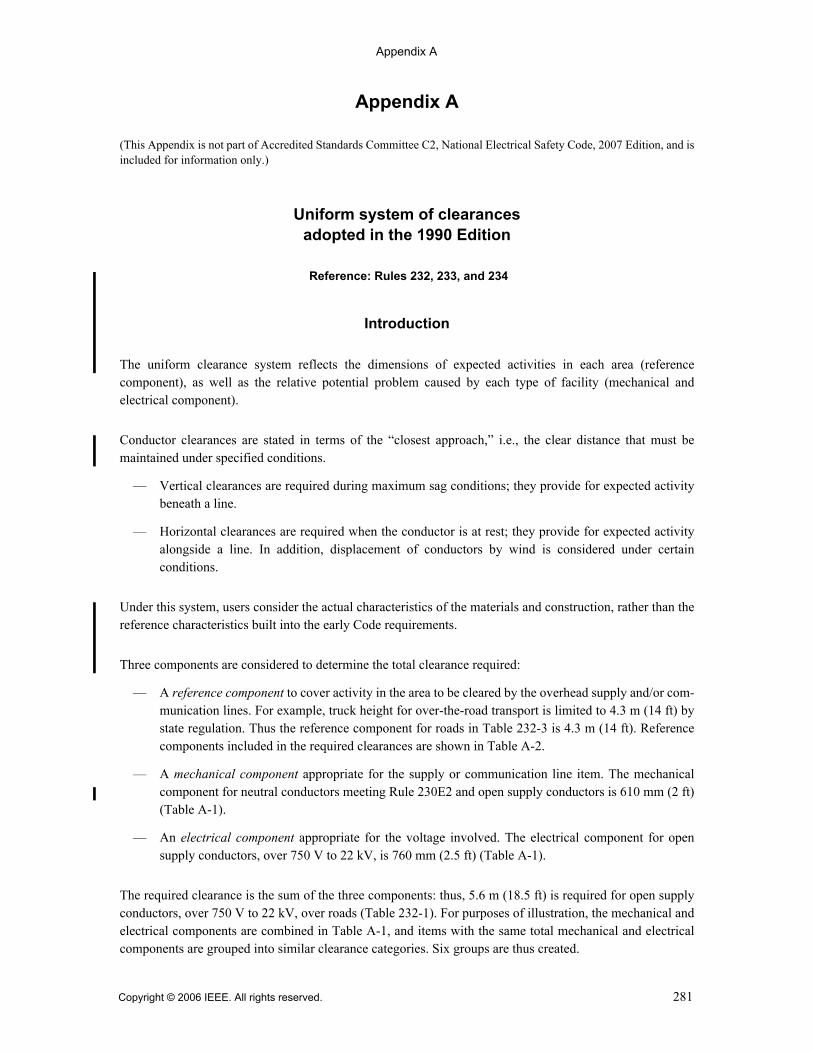
Appendix A
Appendix A
(This Appendix is not part of Accredited Standards Committee C2, National Electrical Safety Code, 2007 Edition, and isincluded for information only.)
Uniform system of clearancesadopted in the 1990 Edition
Reference: Rules 232, 233, and 234
Introduction
The uniform clearance system reflects the dimensions of expected activities in each area (referencecomponent), as well as the relative potential problem caused by each type of facility (mechanical andelectrical component).
Conductor clearances are stated in terms of the “closest approach,” i.e., the clear distance that must bemaintained under specified conditions.
— Vertical clearances are required during maximum sag conditions; they provide for expected activitybeneath a line.
— Horizontal clearances are required when the conductor is at rest; they provide for expected activityalongside a line. In addition, displacement of conductors by wind is considered under certainconditions.
Under this system, users consider the actual characteristics of the materials and construction, rather than thereference characteristics built into the early Code requirements.
Three components are considered to determine the total clearance required:
— A reference component to cover activity in the area to be cleared by the overhead supply and/or com-munication lines. For example, truck height for over-the-road transport is limited to 4.3 m (14 ft) bystate regulation. Thus the reference component for roads in Table 232-3 is 4.3 m (14 ft). Referencecomponents included in the required clearances are shown in Table A-2.
— A mechanical component appropriate for the supply or communication line item. The mechanicalcomponent for neutral conductors meeting Rule 230E2 and open supply conductors is 610 mm (2 ft)(Table A-1).
— An electrical component appropriate for the voltage involved. The electrical component for opensupply conductors, over 750 V to 22 kV, is 760 mm (2.5 ft) (Table A-1).
The required clearance is the sum of the three components: thus, 5.6 m (18.5 ft) is required for open supplyconductors, over 750 V to 22 kV, over roads (Table 232-1). For purposes of illustration, the mechanical andelectrical components are combined in Table A-1, and items with the same total mechanical and electricalcomponents are grouped into similar clearance categories. Six groups are thus created.
Copyright © 2006 IEEE. All rights reserved. 281
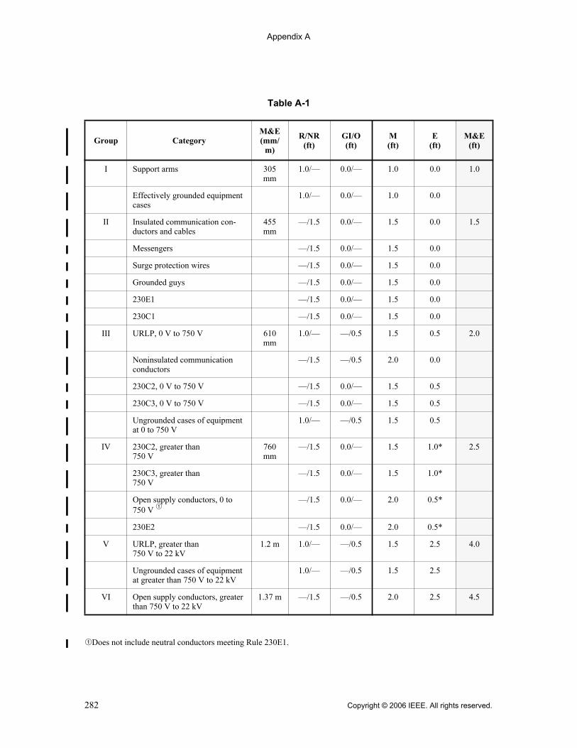
Appendix A
qDoes not include neutral conductors meeting Rule 230E1.
Table A-1
Group CategoryM&E (mm/
m)
R/NR(ft)
GI/O(ft)
M(ft)
E(ft)
M&E(ft)
I Support arms 305 mm
1.0/— 0.0/— 1.0 0.0 1.0
Effectively grounded equipment cases
1.0/— 0.0/— 1.0 0.0
II Insulated communication con-ductors and cables
455 mm
—/1.5 0.0/— 1.5 0.0 1.5
Messengers —/1.5 0.0/— 1.5 0.0
Surge protection wires —/1.5 0.0/— 1.5 0.0
Grounded guys —/1.5 0.0/— 1.5 0.0
230E1 —/1.5 0.0/— 1.5 0.0
230C1 —/1.5 0.0/— 1.5 0.0
III URLP, 0 V to 750 V 610 mm
1.0/— —/0.5 1.5 0.5 2.0
Noninsulated communication conductors
—/1.5 —/0.5 2.0 0.0
230C2, 0 V to 750 V —/1.5 0.0/— 1.5 0.5
230C3, 0 V to 750 V —/1.5 0.0/— 1.5 0.5
Ungrounded cases of equipment at 0 to 750 V
1.0/— —/0.5 1.5 0.5
IV 230C2, greater than 750 V
760 mm
—/1.5 0.0/— 1.5 1.0* 2.5
230C3, greater than 750 V
—/1.5 0.0/— 1.5 1.0*
Open supply conductors, 0 to 750 V q
—/1.5 0.0/— 2.0 0.5*
230E2 —/1.5 0.0/— 2.0 0.5*
V URLP, greater than 750 V to 22 kV
1.2 m 1.0/— —/0.5 1.5 2.5 4.0
Ungrounded cases of equipment at greater than 750 V to 22 kV
1.0/— —/0.5 1.5 2.5
VI Open supply conductors, greater than 750 V to 22 kV
1.37 m —/1.5 —/0.5 2.0 2.5 4.5
282 Copyright © 2006 IEEE. All rights reserved.
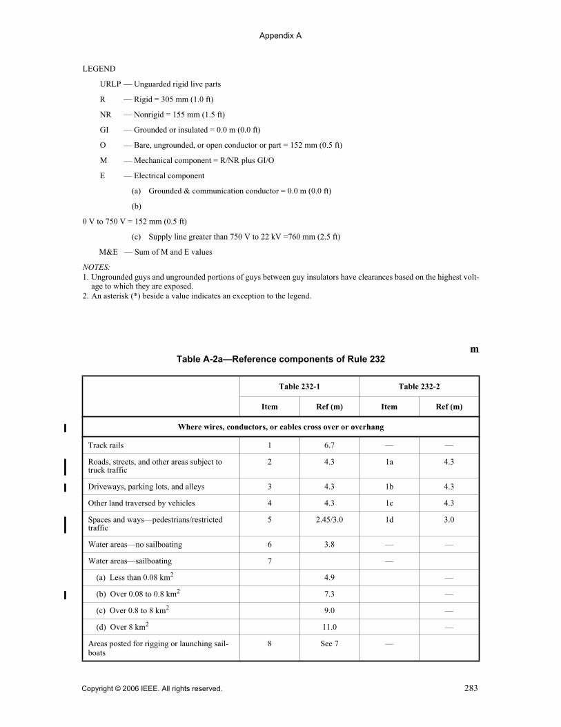
Appendix A
LEGEND
URLP — Unguarded rigid live parts
R — Rigid = 305 mm (1.0 ft)
NR — Nonrigid = 155 mm (1.5 ft)
GI — Grounded or insulated = 0.0 m (0.0 ft)
O — Bare, ungrounded, or open conductor or part = 152 mm (0.5 ft)
M — Mechanical component = R/NR plus GI/O
E — Electrical component
(a) Grounded & communication conductor = 0.0 m (0.0 ft)
(b)
0 V to 750 V = 152 mm (0.5 ft)
(c) Supply line greater than 750 V to 22 kV =760 mm (2.5 ft)
M&E — Sum of M and E values
NOTES: 1. Ungrounded guys and ungrounded portions of guys between guy insulators have clearances based on the highest volt-
age to which they are exposed.2. An asterisk (*) beside a value indicates an exception to the legend.
mTable A-2a—Reference components of Rule 232
Table 232-1 Table 232-2
Item Ref (m) Item Ref (m)
Where wires, conductors, or cables cross over or overhang
Track rails 1 6.7 — —
Roads, streets, and other areas subject to truck traffic
2 4.3 1a 4.3
Driveways, parking lots, and alleys 3 4.3 1b 4.3
Other land traversed by vehicles 4 4.3 1c 4.3
Spaces and ways—pedestrians/restricted traffic
5 2.45/3.0 1d 3.0
Water areas—no sailboating 6 3.8 — —
Water areas—sailboating 7 —
(a) Less than 0.08 km2 4.9 —
(b) Over 0.08 to 0.8 km2 7.3 —
(c) Over 0.8 to 8 km2 9.0 —
(d) Over 8 km2 11.0 —
Areas posted for rigging or launching sail-boats
8 See 7 —
Copyright © 2006 IEEE. All rights reserved. 283

Appendix A
Where wires, conductors, or cables run along and within the limits of highways orother road rights-of-way, but do not overhang the roadway
Roads, streets, or alleys 9 4.3 2a 4.3
Areas where vehicles unlikely 10 3.65 2b 3.65
ftTable A-2a—Reference components of Rule 232
Table 232-1 Table 232-2
Item Ref (ft) Item Ref (ft)
Where wires, conductors, or cables cross over or overhang
Track rails 1 22.0 — —
Roads, streets, and other areas subject to truck traffic 2 14.0 1a 14.0
Driveways, parking lots, and alleys 3 14.0 1b 14.0
Other land traversed by vehicles 4 14.0 1c 14.0
Spaces and ways—pedestrians/restricted traffic 5 8.0/10.0 1d 10.0
Water areas—no sailboating 6 12.5 — —
Water areas—sailboating 7 —
(a) Less than 20 acres 16.0 —
(b) Over 20 to 200 acres 24.0 —
(c) Over 200 to 2000 acres 30.0 —
(d) Over 2000 acres 36.0 —
Areas posted for rigging or launching sailboats 8 See 7 —
Where wires, conductors, or cables run along and within the limits of highways orother road rights-of-way, but do not overhang the roadway
Roads, streets, or alleys 9 14.0 2a 14.0
Areas where vehicles unlikely 10 12.0 2b 12.0
mTable A-2a—Reference components of Rule 232 (continued)
Table 232-1 Table 232-2
Item Ref (m) Item Ref (m)
284 Copyright © 2006 IEEE. All rights reserved.

Appendix A
Vertical clearances now apply at the maximum conductor sag condition, such as outlined in Rule 232A,rather than at a 15 °C (60 °F) conductor temperature condition as used in the 1987 Edition. This is illustratedin Figure A-1: 5.6 m (18.5 ft) is required for open supply conductors, over 750 V to 22 kV, over roads, forany sag condition or span length.
Table A-2b—Reference components of Rule 234
Table Item Ref(mm/m)
Ref(ft)
234-1 1. Buildings
a. Horizontal
(1) Walls, projections, and guarded windows 915 mm 3.0
(2) Unguarded windows 915 mm 3.0
(3) Balconies and areas accessible to pedestrians 915 mm 3.0
b. Vertical
(1) Roofs/projections not accessible to pedestrians 2.44 m 8.0
(2) Balconies and roofs accessible to pedestrians 2.74 m 9.0
(3) Roofs—vehicles not over 2.4 m (8 ft) 2.74 m 9.0
(4) Roofs—vehicles over 2.4 m (8 ft) 4.3 m 14.0
2. Signs, chimneys, billboards, antennas, tanks, etc.
a. Horizontal 915 mm 3.0
b. Vertical over or under 1.07 m 3.5
234-2 1. Over bridges
a. Attached 305 mm 1.0
b. Not attached 2.44 m 8.0
2. Beside, under, or within bridge structure
a. Accessible
(1) Attached 305 mm 1.0
(2) Not attached 915 mm 3.0
b. Inaccessible
(1) Attached 305 mm 1.0
(2) Not attached 610 mm 2.0
234-3 1. From water level, edge of pool, etc. 6.25 m 20.5
2. From diving platform or tower 3.8 m 12.5
Copyright © 2006 IEEE. All rights reserved. 285

Appendix A
Horizontal clearances to buildings and other installations now apply with the conductor at rest (no winddisplacement) as outlined in Rule 234A.
Wind displacement need be considered only for energized open supply conductors and 230C2–230C3 cablesenergized at more than 750 V; see Rule 234C1.
Because application rules were revised in 1990, it must be understood that clearance values cannot bedirectly compared between the 1987 and later editions.
The following changes were also made to consolidate requirements and simplify application:
— Voltages in the tables are limited to 0 V to 750 V and over 750 V to 22 kV, normal secondary andprimary distribution ranges respectively. Voltages in the 22 kV to 50 kV range are covered by a10 mm-per-kV (0.4-in-per-kV) adder; see Rules 232C1a, 232C2a, and 234G1. Exceptions at 22 kVto 50 kV are noted where they apply.
— Rules for voltages above 22 kV and the alternate clearances for voltages above 98 kV areconsolidated.
— Clearances for equipment cases are relocated from Rules 286E and 286F to Rules 232B3 and 234J.
(18.5 ft)CLEARANCE
MAXIMUM SAG CONDITION (50 °C [120 °F], MAXIMUM TEMPERATUREIF GREATER, OR ICE)
MECHANICAL ANDELECTRICAL COMPONENT
(4.5 ft)
(14 ft)
RIGID LIVEPARTCLEARANCE
REFERENCE COMPONENT
REFERENCE COMPONENT(14 ft)
ANY SPAN
CONDITION—CLEARANCE OF OPEN SUPPLY CONDUCTORS, 750 V–22 kV, ABOVE ROADS
CLEARANCE (5.6 m [18.5 ft])= REFERENCE COMPONENT (4.3 m [14 ft])
1.37 m
5.5 m
(18 ft)4.3 m
5.6 m
4.3 m
+ MECHANICAL AND ELECTRICAL COMPONENT (1.37 m [4.5 ft])
Figure A-1—Clearance at maximum sag
286 Copyright © 2006 IEEE. All rights reserved.
Appendix B
Appendix B
(This Appendix is not part of Accredited Standards Committee C2, National Electrical Safety Code, 2007 Edition, and isincluded for information only.)
Uniform clearance calculations for conductors under ice and wind conditions
adopted in the 2007 Edition
Rules 230, 232A, 233A1a(3), 234A1, 235C2b(1)(c), Definitions
Considerable activity over a period of several years took place preparing Change Proposals for the 2007Code Edition. These proposals reflect subcommittee response to proposed changes in strength and loadingrules, and are in preparation for further potential changes.
A major issue addressed was that of the greater conductor sag that will result from the increased radial icethickness shown on the new ice map (Figure 250-3) in Section 25. These increases have made it necessary toreevaluate the impact such sags would have by effectively reducing overhead clearances. Furthermore itappears that the revised map(s) may become the only source of icing information in the future and may beupdated periodically. Ice and wind maps as published by the American Society of Civil Engineers areimportant sources of meteorological information especially prepared for structural design.
A study using a spread of commonly used power cables revealed that in many areas very significant sagincreases would result from increased ice, as compared to those values shown in Table 250-1. To respond tothis challenge a working group comprised of members from Subcommittees 4 and 5 was formed to deviseviable solutions. Few constraints were placed on their work except that the level of safety currently in effectmust not be compromised.
Working Group activities
Several approaches were suggested as possible mitigating solutions. Each had merit and essentially achieveda reduction in sag by rationalizing a lesser thickness than was called for in the revised ice map. One suchmethod lowered the storm return period from the established base line of 50 years (2% probability in a givenyear) to 12 or 15 years (8-1/3% to 6-2/3% probability in a given year). The method had merit, was carefullyevaluated, but had some apparent disadvantages.
A more simple and direct approach which received universal Working Group acceptance, recognized thatthe new ice map is used exclusively for calculating ice and wind loads as related to strength and loading.Alternatively, when calculating sag for clearance purposes, a separate and different ice/wind map appearingin Section 23 would be employed, which is equivalent to the present Figure 250-1.
The loading district terminology heavy, medium, and light has been replaced by clearance zones 1, 2, and 3,respectively. This eliminates the potential for confusion between the ice/wind requirements to be applied inboth Sections 23 and 25, if Section 25 changes in the future. Section 23 will contain all clearance rules, as isappropriate, and will apply sags that are derived from radial ice thickness requirements in the 2002 Edition.The credibility of these clearances was established many years ago since they are based upon a safety recordof some 70 years of success.
Copyright © 2006 IEEE. All rights reserved. 287

Appendix B
Calculating clearance 2007 Edition
The following is a brief description of the methodology for calculating clearance related sags:
— Rule 230B1. Clearance zones have replaced “loading districts” for classifying areas where combinedice and wind effects on conductors are essentially equivalent. Clearance zones 1, and 2, and 3 areequivalent to heavy, medium, and light loading districts in the 2002 Edition. These zones are shownin new Figure 230-1. The boundaries for this map are unchanged from previous editions of Rule 250.
— Table 230-1 and 230-2. These tables show in tabular form the radial ice thickness, wind pressure,temperatures, and additive constants used to calculate clearance sags. Long term creep determinationrequires additional information that is not provided in the code and may or may not be a factor in agiven design. The specified radial ice, wind pressures, temperatures, and additive constants in thethree zones are the same as those in Rule 250 of the 2002 Edition.
— Sag definitions. These have been slightly modified for reasons discussed under conductor creep inthis Appendix.
— Rules 232A3, 233A1a(3), 234A1, and 235C2b(1)(c). Appropriate additions of, and deletions to,these rules were necessary in order to account for the move of clearance related calculations fromSection 25 to Section 23 in the 2007 Edition.
— Rule 230B3. This rule is the equivalent of Rule 251A of the 2007 Edition.
— Rule 230B4. This rule is the equivalent of Rule 251B of the 2002 Edition.
Conductor creep
Creep is a complex physical property of most structural metals and relates to strain hardening and boundarymovement at the molecular level. It is important in the design of many transmission lines, as well as in somedistribution designs. It is mentioned in the 2002 and previous editions. Unfortunately, it is not always wellunderstood, especially the difference between initial stretch and creep, the latter being a function of bothtemperature and time. Both, however, are forms of inelastic deformation, but occur over very different timeperiods.
All conductors and support messengers experience initial stretch immediately upon loading. Upon removalof the load, the conductor will return to an unloaded position that is displaced from the initial position.Repeated loading to higher magnitudes progressively shifts the elastic line, and the linear relationshipbetween load and strain thereafter acts along this line.
Creep however, varies as a function of time, but not linearly. Some conductors are provided with creepcurves covering different periods of time at specified temperatures. Many engineers consider 10 years as thepractical limit for creep to increase, after which time it remains fairly static.
Experience has also shown that steel is much less prone to creep as compared to aluminum or copper, and iscommonly ignored for steel wires and messengers. Aluminum conductors on the other hand are highly sus-ceptible to creep, particularly at elevated temperatures, and usually require attention during the design stage.
The unique characteristics of creep and its occasional confusion with initial stretch led the working group tostrike parenthetical creep from the definitions of sag. Creep remains a factor engineers must consider in theirwork with the Code because it is a form of inelastic deformation. The action also removed the apparent (andprobably unintentional) emphasis placed on creep, when in fact for smaller conductors it generally has lessimpact on clearance than does initial stretch.
288 Copyright © 2006 IEEE. All rights reserved.

Appendix B
Summary
The Code safety principles, and design practices, have for over seventy years successfully protected both thepublic and utility workers from injury and death. The same standards have been carefully applied whiledeveloping these revisions. Changes in the 2007 Edition with respect to clearance calculations may be char-acterized as follows:
— All requirements for overhead line clearances are now incorporated in Section 23.
— Calculations to meet electrical and mechanical clearance requirements remain essentiallyunchanged.
— Responsible subcommittees exercise complete control in their area. This will allow for potentiallydifferent treatment of conductor tension and conductor sags when applied to structural loading and toclearances in the future.
— Persons not familiar with strength concerns are not encumbered with unrelated design issues, andvice versa.
— Subcommittees 4 and 5 will be better postured to work with other standards producing organizations.
— Improved and updated weather maps and similar aids can be more readily implemented.
Copyright © 2006 IEEE. All rights reserved. 289

Appendix C
Appendix C
(This Appendix is not part of Accredited Standards Committee C2, National Electrical Safety Code, 2007 Edition, and isincluded for information only.)
Example applications for Rule 250C Tables 250-2 and 250-3
The following four examples demonstrate the use of Tables 250-2 and 250-3. The method of selecting thedesign parameters should not be considered the recommended method for the structures presented in theseexamples. The method used for determining the design values should be based on engineering judgment.
Example 1 demonstrates the basic application for determining the tower and wire wind loads. The towerwind load is uniformly distributed over the tower height (h).
Step 1: Determine the wind pressure for the phase conductors
Using Table 250-2, select a wire kz value, velocity pressure exposure coefficient:
The kz for the wire is based on the height, h, of the wire at the structure (Rule 250C1), h = 24.2 m (79.4 ft);therefore from Table 250-2, kz = 1.20. The table kz values represent, approximately, the upper limit for therange of heights, h. The equations of Table 250-2 can be used to determine the exact value of kz.
Using Table 250-3, select a wire GRF value, gust response factor:
kz = 2.01 · (24.2 m/275 m)(2/9.5) = 1.205
kz = 2.01 · (79.4 ft/900 ft)(2/9.5) = 1.205
Example 1
290 Copyright © 2006 IEEE. All rights reserved.

Appendix C
The wire gust response factor, GRF, is determined using the height of the wire at the structure, h = 24.2 m(79.4 ft), and the design wind span, L. The design span for this example is assumed to be 400 m (1310 ft).Using Table 250-3, the Wire GRF equals 0.69. The table values represent, approximately, the upper limit ofthe GRF value based on the upper limit for the range of heights, h, and lower limit for the range of spanlengths, L. The equations of Table 250-3 can be used to determine the exact value of GRF.
The wire wind pressure, assuming 40 m/s (90 mph), I and Cd equal 1.0, and the table values for kz and GRF,is
Step 2: Determine the wind pressure for the overhead groundwire
Using Table 250-2, select a wire kz value, velocity pressure exposure coefficient:
The kz for the wire is based on the height, h, of the wire at the structure (Rule 250C1), h = 31.4 m (103 ft);therefore from Table 250-2, kz = 1.30. The equations of Table 250-2 can be used to determine the exactvalue of kz.
Using Table 250-3, select a wire GRF value, gust response factor:
The wire gust response factor, GRF, is determined using the height of the wire at the structure, h = 31.4 m(103 ft), and the design wind span, L = 400 m (1310 ft). Using Table 250-3, the overhead groundwire GRFequals 0.68. The equations of Table 250-3 can be used to determine the exact value of GRF.
Bw = 1/(1 + 0.8 · 400 m/67) = 0.173
Ew = 0.346 · (10/24.2 m)1/7 = 0.305
GRF = [1 + (2.7 · 0.305 · (0.173)0.5)]/ (1.43)2 = 0.657
Bw = 1/(1 + 0.8 · 1310 ft/220) = 0.173
Ew = 0.346 · (33/79.4 ft)1/7 = 0.305
GRF = [1 + (2.7 · 0.305 · (0.173)0.5)]/ (1.43)2 = 0.657
Wind pressure = 0.613 · (40 m/s)2 · 1.2 · 0.69 · 1.0 · 1.0 = 812 newtons/m2
Wind pressure = 0.00256 · (90 mph)2 · 1.2 · 0.69 · 1.0 · 1.0 = 17.17 psf
kz = 2.01 · (31.4 m/275 m)(2/9.5) = 1.273
kz = 2.01 · (103 ft/900 ft)(2/9.5) = 1.273
Bw = 1/(1 + 0.8 · 400 m/67) = 0.173
Ew = 0.346 · (10/31.4 m)1/7 = 0.294
GRF = [1 + (2.7 · 0.294 · (0.173)0.5)] / (1.43)2 = 0.650
Bw = 1/(1 + 0.8 · 1310 ft/220) = 0.173
Ew = 0.346 · (33/103 ft)1/7 = 0.294
GRF = [1 + (2.7 · 0.294 · (0.173)0.5)]/ (1.43)2 = 0.650
Copyright © 2006 IEEE. All rights reserved. 291
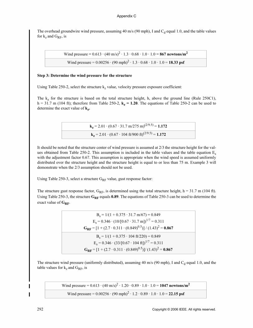
Appendix C
The overhead groundwire wind pressure, assuming 40 m/s (90 mph), I and Cd equal 1.0, and the table valuesfor kz and GRF, is
Step 3: Determine the wind pressure for the structure
Using Table 250-2, select the structure kz value, velocity pressure exposure coefficient:
The kz for the structure is based on the total structure height, h, above the ground line (Rule 250C1),h = 31.7 m (104 ft); therefore from Table 250-2, kz = 1.20. The equations of Table 250-2 can be used todetermine the exact value of kz.
It should be noted that the structure center of wind pressure is assumed at 2/3 the structure height for the val-ues obtained from Table 250-2. This assumption is included in the table values and the table equation Eswith the adjustment factor 0.67. This assumption is appropriate when the wind speed is assumed uniformlydistributed over the structure height and the structure height is equal to or less than 75 m. Example 3 willdemonstrate when the 2/3 assumption should not be used.
Using Table 250-3, select a structure GRF value, gust response factor:
The structure gust response factor, GRF, is determined using the total structure height, h = 31.7 m (104 ft).Using Table 250-3, the structure GRF equals 0.89. The equations of Table 250-3 can be used to determine theexact value of GRF.
The structure wind pressure (uniformly distributed), assuming 40 m/s (90 mph), I and Cd equal 1.0, and thetable values for kz and GRF, is
Wind pressure = 0.613 · (40 m/s)2 · 1.3 · 0.68 · 1.0 · 1.0 = 867 newtons/m2
Wind pressure = 0.00256 · (90 mph)2 · 1.3 · 0.68 · 1.0 · 1.0 = 18.33 psf
kz = 2.01 · (0.67 · 31.7 m/275 m)(2/9.5) = 1.172
kz = 2.01 · (0.67 · 104 ft/900 ft)(2/9.5) = 1.172
Bs = 1/(1 + 0.375 · 31.7 m/67) = 0.849
Es = 0.346 · (10/[0.67 · 31.7 m])1/7 = 0.311
GRF = [1 + (2.7 · 0.311 · (0.849)0.5)] / (1.43)2 = 0.867
Bs = 1/(1 + 0.375 · 104 ft/220) = 0.849
Es = 0.346 · (33/[0.67 · 104 ft])1/7 = 0.311
GRF = [1 + (2.7 · 0.311 · (0.849)0.5)]/ (1.43)2 = 0.867
Wind pressure = 0.613 · (40 m/s)2 · 1.20 · 0.89 · 1.0 · 1.0 = 1047 newtons/m2
Wind pressure = 0.00256 · (90 mph)2 · 1.2 · 0.89 · 1.0 · 1.0 = 22.15 psf
292 Copyright © 2006 IEEE. All rights reserved.

Appendix C
Example 2 demonstrates the engineer’s judgment that the center of wind pressure for a Delta wire configu-ration is at the mid-height of the wire configuration.
Determine the wind pressure for the phase conductors.
Using Table 250-2, select a wire kz value, velocity pressure exposure coefficient:
The kz for the wire is based on the height, h, of the center of the wire locations, h = 22.1 m (72.5 ft); there-fore from Table 250-2, kz = 1.20. The equations of Table 250-2 can be used to determine the exact value kz.
Using Table 250-3, select a wire GRF value, gust response factor:
The wire gust response factor, GRF, is determined using the height of the wire at the center of the wire Deltaconfiguration, h = 22.1 m (72.5 ft), and the design wind span, L. The design wind span for this example isassumed to be 275 m (900 ft). Using the table, the wire GRF equals 0.71. The equations of Table 250-3 canbe used to determine the exact value of GRF.
kz = 2.01 · (22.1 m/275 m)(2/9.5) = 1.182
kz = 2.01 · (72.5 ft/900 ft)(2/9.5) = 1.182
Example 2
Copyright © 2006 IEEE. All rights reserved. 293

Appendix C
The wire wind pressure, assuming 38 m/s (85 mph), I and Cd equal 1.0, and the table values for kz and GRF,is
Example 3 demonstrates the application of a non-uniform wind load distribution for structures taller than250 m. This procedure may also be used on structures less than 250 m when in the engineer’s judgment adetailed wind load distribution is desired.
Step 1: Determine assumed wind load distribution
This structure is assumed to have 4 different wind sections (WS) each with its specific uniform wind load.Wind Section #1 (WS#1) was determined by engineering judgment to be the height, h, from the ground lineto the top of the tapered leg, h = 69.5 m (228 ft). The center of wind pressure for WS#1 is assumed to be 2/3the height of 69.5 m (228 ft). WS#2 is assumed to be the distance between the top of the tapered leg to thebottom of the middle crossarm. The center of wind pressure for WS#2 is assumed to be at the mid-height ofthis wind section, h = 75.8 m (248 ft). Similar assumptions are made for WS#3, h = 88.3 m (290 ft), andWS#4, h = 100.3 m (329 ft).
Step 2: Determine the wind load for each structure wind section
For WS#1, determine the uniformly distributed wind load.
Determine kz, h = 69.5 m (228 ft), using Table 250-2, kz = 1.40, using the equations:
Determine GRF. The structure gust response factor is a function of the structures dynamic response. There-fore a single value of GRF using the total structure height should be used on all structure wind sections.Given h = 106.1 m (348 ft), using the equations:
Bw = 1/(1 + 0.8 · 275 m/67) = 0.233
Ew = 0.346 · (10/22.1 m)1/7 = 0.309
GRF = [1 + (2.7 · 0.309 · (0.233)0.5)]/ (1.43)2 = 0.686
Bw = 1/(1 + 0.8 · 900 ft/220) = 0.233
Ew = 0.346 · (33/72.5 ft)1/7 = 0.309
GRF = [1 + (2.7 · 0.309 · (0.233)0.5)]/ (1.43)2 = 0.686
Wind pressure = 0.613 · (38 m/s)2 · 1.2 · 0.71 · 1.0 · 1.0 = 754 newtons/m2
Wind pressure = 0.00256 · (85 mph)2 · 1.2 · 0.71 · 1.0 · 1.0 = 15.76 psf
kz 2.01 · (0.67 · 69.5 m/275 m)(2/9.5) = 1.383
kz 2.01 · (0.67 · 228 ft/900 ft)(2/9.5) = 1.383
294 Copyright © 2006 IEEE. All rights reserved.

Appendix C
The structure wind pressure (uniformly distributed over WS#1) assuming 40 m/s (90 mph), I and Cd equal1.0:
For WS#2, determine the uniformly distributed wind load.
Determine kz, h = 75.8 m (248 ft), using the equations:
Bs = 1/(1 + 0.375 · 106.1 m/67) = 0.627
Es = 0.346 · (10/[0.67 · 106.1 m])1/7 = 0.261
GRF = [1 + (2.7 · 0.261 · (0.627)0.5)] / (1.43)2 = 0.762
Bs = 1/(1 + 0.375 · 348 ft/220) = 0.627
Es = 0.346 · (33/[0.67 · 348 ft])1/7 = 0.261
GRF = [1 + (2.7 · 0.261 · (0.627)0.5)]/ (1.43)2 = 0.762
Wind pressure = 0.613 · (40 m/s)2 · 1.40 · 0.762 · 1.0 · 1.0 = 1046 newtons/m2
Wind pressure = 0.00256 · (90 mph)2 · 1.40 · 0.762 · 1.0 · 1.0 = 22.12 psf
Example 3
Copyright © 2006 IEEE. All rights reserved. 295

Appendix C
GRF = 0.762 for the overall structure, thus the structure wind pressure (uniformly distributed over WS#2)assuming 40 m/s (90 mph), I and Cd equal 1.0:
For WS#3, determine the uniformly distributed wind load.
Determine kz, h = 88.3 m (290 ft), using the equations:
GRF = 0.762. The structure wind pressure (uniformly distributed over WS#3) assuming 40 m/s (90 mph), Iand Cd equal 1.0:
For WS#4, determine the uniformly distributed wind load. Determine kz, h = 100.3 m (329 ft), using theequations:
GRF = 0762. The structure wind pressure (uniformly distributed over WS#4) assuming 40 m/s (90 mph), Iand Cd equal 1.0:
Example 4 demonstrates the application of wind load on a distribution wood structure. The purpose of thisexample is to demonstrate the concept provided in Rule 250C. Engineering judgment should be used whenselecting the wind parameters to use with Tables 250-2 and 250-3.
Step 1: Determine the wind pressure for the phase conductors
kz = 2.01 · (75.8 m/275 m)(2/9.5) = 1.53
kz 2.01 · (248 ft/900 ft)(2/9.5) = 1.53
Wind pressure = 0.613 · (40 m/s)2 · 1.53 · 0.762 · 1.0 · 1.0 = 1143 newtons/m2
Wind pressure = 0.00256 · (90 mph)2 · 1.53 · 0.762 · 1.0 · 1.0 = 24.18 psf
kz = 2.01 · (88.3 m/275 m)(2/9.5) = 1.58
kz 2.01 · (290 ft/900 ft)(2/9.5) = 1.58
Wind pressure = 0.613 · (40 m/s)2 · 1.58 · 0.762 · 1.0 · 1.0 = 1181 newtons/m2
Wind pressure = 0.00256 · (90 mph)2 · 1.58 · 0.762 · 1.0 · 1.0 = 24.97 psf
kz = 2.01 · (100.3 m/275 m)(2/9.5) = 1.63
kz 2.01 · (329 ft/900 m)(2/9.5) = 1.63
Wind pressure = 0.613 · (40 m/s)2 · 1.63 · 0.762 · 1.0 · 1.0 = 1218 newtons/m2
Wind pressure = 0.00256 · (90 mph)2 · 1.63 · 0.762 · 1.0 · 1.0 = 25.75 psf
296 Copyright © 2006 IEEE. All rights reserved.
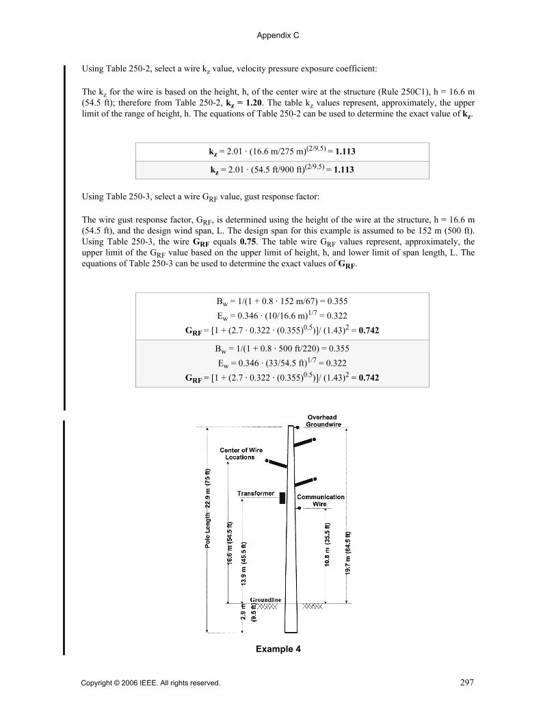
Appendix C
Using Table 250-2, select a wire kz value, velocity pressure exposure coefficient:
The kz for the wire is based on the height, h, of the center wire at the structure (Rule 250C1), h = 16.6 m(54.5 ft); therefore from Table 250-2, kz = 1.20. The table kz values represent, approximately, the upperlimit of the range of height, h. The equations of Table 250-2 can be used to determine the exact value of kz.
Using Table 250-3, select a wire GRF value, gust response factor:
The wire gust response factor, GRF, is determined using the height of the wire at the structure, h = 16.6 m(54.5 ft), and the design wind span, L. The design span for this example is assumed to be 152 m (500 ft).Using Table 250-3, the wire GRF equals 0.75. The table wire GRF values represent, approximately, theupper limit of the GRF value based on the upper limit of height, h, and lower limit of span length, L. Theequations of Table 250-3 can be used to determine the exact values of GRF.
kz = 2.01 · (16.6 m/275 m)(2/9.5) = 1.113
kz = 2.01 · (54.5 ft/900 ft)(2/9.5) = 1.113
Bw = 1/(1 + 0.8 · 152 m/67) = 0.355
Ew = 0.346 · (10/16.6 m)1/7 = 0.322
GRF = [1 + (2.7 · 0.322 · (0.355)0.5)]/ (1.43)2 = 0.742
Bw = 1/(1 + 0.8 · 500 ft/220) = 0.355
Ew = 0.346 · (33/54.5 ft)1/7 = 0.322
GRF = [1 + (2.7 · 0.322 · (0.355)0.5)]/ (1.43)2 = 0.742
Example 4
Copyright © 2006 IEEE. All rights reserved. 297

Appendix C
The wire wind pressure, assuming 40 m/s (90 mph), I and Cd equal 1.0, and the table values for kz and GRF,is
Step 2: Determine the wind pressure for the overhead groundwire
Using Table 250-2, select a wire kz value, velocity pressure exposure coefficient:
The kz for the wire is based on the height, h, of the wire at the structure (Rule 250C1), h = 19.7 m (64.5 ft);therefore from Table 250-2, kz = 1.20. The equations of Table 250-2 can be used to determine the exactvalue of kz.
Using Table 250-3, select a wire GRF value, gust response factor:
The wire gust response factor, GRF, is determined using the height of the wire at the structure, h = 19.7 m(64.5 ft), and the design wind span, L = 152 m (500 ft). Using Table 250-3, the overhead groundwire GRFequals 0.75. The equations of Table 250-3 can be used to determine the exact value of GRF.
The overhead groundwire wind pressure, assuming 40 m/s (90 mph), I and Cd equal 1.0, and the table valuesfor kz and GRF, is
Step 3: Determine the wind pressure for the structure
Using Table 250-2, select the structure kz value, velocity pressure exposure coefficient:
The kz for the structure is based on the total structure height, h, above the ground line (Rule 250C1),h = 22.9 m – 2.9 m = 20.0 m (75 ft – 9.5 ft = 65.5 ft); therefore from Table 250-2, kz = 1.10. The equationsof Table 250-2 can be used to determine the exact value of kz.
Wind pressure = 0.613 · (40 m/s)2 · 1.2 · 0.75 · 1.0 · 1.0 = 883 newtons/m2
Wind pressure = 0.00256 · (90 mph)2 · 1.2 · 0.75 · 1.0 · 1.0 = 18.66 psf
kz = 2.01 · (19.7 m/275 m)(2/9.5) = 1.154
kz = 2.01 · (64.5 ft/900 ft)(2/9.5) = 1.154
Bw = 1/(1 + 0.8 · 152 m/67) = 0.355
Ew = 0.346 · (10/19.7 m)1/7 = 0.314
GRF = [1 + (2.7 · 0.314 · (0.355)0.5)] / (1.43)2 = 0.736
Bw = 1/(1 + 0.8 · 500 ft/220) = 0.355
Ew = 0.346 · (33/64.5ft)1/7 = 0.314
GRF = [1 + (2.7 · 0.314 · (0.355)0.5)]/ (1.43)2 = 0.736
Wind pressure = 0.613 · (40 m/s)2 · 1.2 · 0.75 · 1.0 · 1.0 = 883 newtons/m2
Wind pressure = 0.00256 · (90 mph)2 · 1.2 · 0.75 · 1.0 · 1.0 = 18.66 psf
298 Copyright © 2006 IEEE. All rights reserved.
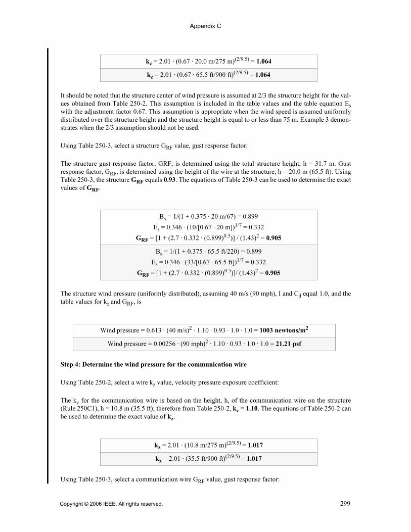
Appendix C
It should be noted that the structure center of wind pressure is assumed at 2/3 the structure height for the val-ues obtained from Table 250-2. This assumption is included in the table values and the table equation Eswith the adjustment factor 0.67. This assumption is appropriate when the wind speed is assumed uniformlydistributed over the structure height and the structure height is equal to or less than 75 m. Example 3 demon-strates when the 2/3 assumption should not be used.
Using Table 250-3, select a structure GRF value, gust response factor:
The structure gust response factor, GRF, is determined using the total structure height, h = 31.7 m. Gustresponse factor, GRF, is determined using the height of the wire at the structure, h = 20.0 m (65.5 ft). UsingTable 250-3, the structure GRF equals 0.93. The equations of Table 250-3 can be used to determine the exactvalues of GRF.
The structure wind pressure (uniformly distributed), assuming 40 m/s (90 mph), I and Cd equal 1.0, and thetable values for kz and GRF, is
Step 4: Determine the wind pressure for the communication wire
Using Table 250-2, select a wire kz value, velocity pressure exposure coefficient:
The kz for the communication wire is based on the height, h, of the communication wire on the structure(Rule 250C1), h = 10.8 m (35.5 ft); therefore from Table 250-2, kz = 1.10. The equations of Table 250-2 canbe used to determine the exact value of kz.
Using Table 250-3, select a communication wire GRF value, gust response factor:
kz = 2.01 · (0.67 · 20.0 m/275 m)(2/9.5) = 1.064
kz = 2.01 · (0.67 · 65.5 ft/900 ft)(2/9.5) = 1.064
Bs = 1/(1 + 0.375 · 20 m/67) = 0.899
Es = 0.346 · (10/[0.67 · 20 m])1/7 = 0.332
GRF = [1 + (2.7 · 0.332 · (0.899)0.5)] / (1.43)2 = 0.905
Bs = 1/(1 + 0.375 · 65.5 ft/220) = 0.899
Es = 0.346 · (33/[0.67 · 65.5 ft])1/7 = 0.332
GRF = [1 + (2.7 · 0.332 · (0.899)0.5)]/ (1.43)2 = 0.905
Wind pressure = 0.613 · (40 m/s)2 · 1.10 · 0.93 · 1.0 · 1.0 = 1003 newtons/m2
Wind pressure = 0.00256 · (90 mph)2 · 1.10 · 0.93 · 1.0 · 1.0 = 21.21 psf
kz = 2.01 · (10.8 m/275 m)(2/9.5) = 1.017
kz = 2.01 · (35.5 ft/900 ft)(2/9.5) = 1.017
Copyright © 2006 IEEE. All rights reserved. 299

Appendix C
The wire gust response factor, GRF, is determined using the height of the communication wire at the struc-ture, h = 10.8 m (35.5 ft), and the design wind span, L = 152 m (500 ft). Using Table 250-3, the communica-tion wire GRF equals 0.76. The equations of Table 250-3 can be used to determine the exact value of GRF.
The communication wire wind pressure, assuming 40 m/s (90 mph), I and Cd equal 1.0, and the table valuesfor kz and GRF, is
Step 5: Determine the wind pressure for the transformer
Using Table 250-2, select a transformer kz value, velocity pressure exposure coefficient:
The kz for the transformer is based on the height, h, of the transformer on the structure (Rule 250C1), h =13.9 m (45.5 ft); therefore from Table 250-2, kz = 1.10. The equations of Table 250-2 can be used to deter-mine the exact value of kz.
The transformer GRF value, gust response factor, is 0.93, Rule 250C2.
The transformer wind pressure, assuming 40 m/s (90 mph), I and Cd equal 1.0, and the table values for kzand GRF, is
Bw = 1/(1 + 0.8 · 152 m/67) = 0.355
Ew = 0.346 · (10/10.8 m)1/7 = 0.342
GRF = [1 + (2.7 · 0.342 · (0.355)0.5)] / (1.43)2 = 0.758
Bw = 1/(1 + 0.8 · 500 ft/220) = 0.355
Ew = 0.346 · (33/35.5 ft)1/7 = 0.342
GRF = [1 + (2.7 · 0.342 · (0.355)0.5)]/ (1.43)2 = 0.758
Wind pressure = 0.613 · (40 m/s)2 · 1.1 · 0.76 · 1.0 · 1.0 = 820 newtons/m2
Wind pressure = 0.00256 · (90 mph)2 · 1.1 · 0.76 · 1.0 · 1.0 = 17.34 psf
kz = 2.01 · (13.9 m/275 m)(2/9.5) = 1.072
kz = 2.01 · (45.5 ft/900 ft)(2/9.5) = 1.072
Wind pressure = 0.613 · (40 m/s)2 · 1.1 · 0.93 · 1.0 · 1.0 = 1003 newtons/m2
Wind pressure = 0.00256 · (90 mph)2 · 1.1 · 0.93 · 1.0 · 1.0 = 21.21 psf
300 Copyright © 2006 IEEE. All rights reserved.
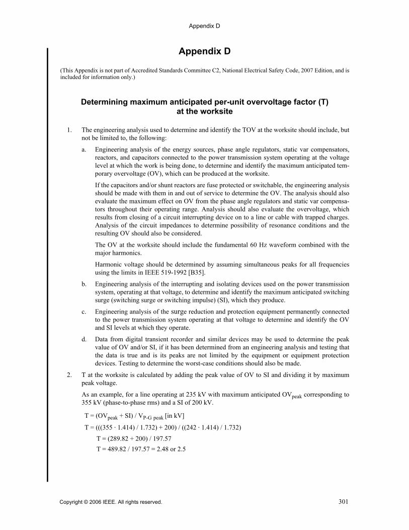
Appendix D
Copyright © 2006 IEEE. All rights reserved. 301
Appendix D
(This Appendix is not part of Accredited Standards Committee C2, National Electrical Safety Code, 2007 Edition, and isincluded for information only.)
Determining maximum anticipated per-unit overvoltage factor (T) at the worksite
1. The engineering analysis used to determine and identify the TOV at the worksite should include, butnot be limited to, the following:
a. Engineering analysis of the energy sources, phase angle regulators, static var compensators,reactors, and capacitors connected to the power transmission system operating at the voltagelevel at which the work is being done, to determine and identify the maximum anticipated tem-porary overvoltage (OV), which can be produced at the worksite.
If the capacitors and/or shunt reactors are fuse protected or switchable, the engineering analysisshould be made with them in and out of service to determine the OV. The analysis should alsoevaluate the maximum effect on OV from the phase angle regulators and static var compensa-tors throughout their operating range. Analysis should also evaluate the overvoltage, whichresults from closing of a circuit interrupting device on to a line or cable with trapped charges.Analysis of the circuit impedances to determine possibility of resonance conditions and theresulting OV should also be considered.
The OV at the worksite should include the fundamental 60 Hz waveform combined with themajor harmonics.
Harmonic voltage should be determined by assuming simultaneous peaks for all frequenciesusing the limits in IEEE 519-1992 [B35].
b. Engineering analysis of the interrupting and isolating devices used on the power transmissionsystem, operating at that voltage, to determine and identify the maximum anticipated switchingsurge (switching surge or switching impulse) (SI), which they produce.
c. Engineering analysis of the surge reduction and protection equipment permanently connectedto the power transmission system operating at that voltage to determine and identify the OVand SI levels at which they operate.
d. Data from digital transient recorder and similar devices may be used to determine the peakvalue of OV and/or SI, if it has been determined from an engineering analysis and testing thatthe data is true and is its peaks are not limited by the equipment or equipment protectiondevices. Testing to determine the worst-case conditions should also be made.
2. T at the worksite is calculated by adding the peak value of OV to SI and dividing it by maximumpeak voltage.
As an example, for a line operating at 235 kV with maximum anticipated OVpeak corresponding to355 kV (phase-to-phase rms) and a SI of 200 kV.
T = (OVpeak + SI) / VP-G peak [in kV]
T = (((355 ⋅ 1.414) / 1.732) + 200) / ((242 ⋅ 1.414) / 1.732)
T = (289.82 + 200) / 197.57
T = 489.82 / 197.57 = 2.48 or 2.5
Appendix E
Appendix E
Bibliography
[B1] ANSI A14.1-1994, American National Standard Safety Requirements for Portable Wood Ladders.[Rule 323F REC]f
[B2] ANSI A14.2-1990, American National Standard Safety Requirements for Portable Metal Ladders [andsupplement ANSI 14.2a (1985)]. [Rule 323F REC]
[B3] ANSI A14.3-1992, American National Standard Safety Requirements for Fixed Ladders. [Rule 323FREC]
[B4] ANSI A14.5-1992, American National Standard Safety Requirements for Portable Reinforced PlasticLadders [and supplement ANSI A14.5a (1985)]. [Rule 323F REC]
[B5] ANSI A1264.1-1995, American National Safety Requirements for Workplace Floor and WallOpenings. [Rule 112D NOTE]
[B6] ANSI C2-1973, National Electrical Safety Code. [Rule 402 NOTE]
[B7] ANSI C29.8-1985 (R2002), American National Standard for Wet-Process Porcelain Insulators—Apparatus, Cap, and Pin Type.
[B8] ANSI C29.9-1983 (R2002), American National Standard for Wet-Process Porcelain Insulators—Apparatus, Post Type. [Rule 277 NOTE 2]
[B9] ANSI C29.10-1989 (R2002), American National Standard for Wet-Process Porcelain Insulators—Indoor Apparatus Type.
[B10] ANSI C29.11-1989 (R1996), American National Standard for Composite Suspension Insulators forOverhead Transmission Lines—Tests. [Rule 277 NOTE 1b]
[B11] ANSI C29.12-1997 (R2002), American National Standard for Insulators—Composite SuspensionType.
[B12] ANSI C29.13-2000, American National Standard for Insulators—Composite-Distribution DeadendType.
[B13] ANSI C29.17-2002, American National Standard for Insulators—Composite-Line Post Type.
[B14] ANSI C29.18-2003, American National Standard for Insulators—Composite-Distribution Line PostType.
[B15] ANSI O5.2-1996 (Reaff 2001), American National Standard for Wood Products—Structural GluedLaminated Timber for Utility Structures. [Rule 261A]
[B16] ANSI O5.3-2002, American National Standard for Solid Sawn-wood Crossarms and Braces—Specifications and Dimensions. [Rule 261A]
fANSI publications are available from the Sales Department, American National Standards Institute, 25 West 43rd Street, 4th Floor,New York, NY 10036, USA (http://www.ansi.org/).
302 Copyright © 2006 IEEE. All rights reserved.

Appendix E
[B17] API RP 500, Recommended Practice for Classification of Locations for Electrical Installations atPetroleum Facilities, 7 January 1998. [Rule 127L NOTE]g
[B18] ASTM F 478-92 (1999), Standard Specification for In-Service Care of Insulating Line Hose andCovers.h
[B19] ASTM F 479-95 (2001), Standard Specification for In-Service Care of Insulating Blankets.
[B20] ASTM F 496-02A/e01, Standard Specification for In-Service Care of Insulating Gloves and Sleeves.
[B21] ASTM F 696-02, Standard Specification for Leather Protectors for Rubber Insulating Gloves andMittens.
[B22] ASTM F 711-02, Standard Specification for Fiberglass-Reinforced Plastic (FRP) Rod and Tube Usedin Live Line Tools.
[B23] ASTM F 855-04, Standard Specification for Temporary Grounding Systems to Be Used on De-energized Electric Power Lines and Equipment.
[B24] ASTM F 887-05, Standard Specification for Personal Climbing Equipment.
[B25] ASTM F 914-03, Standard Test Method for Acoustic Emission for Insulated Aerial PersonnelDevices.
[B26] ASTM F 968-93 (2002/e01), Standard Specification for Electrically Insulating Plastic GuardEquipment for Protection of Workers.
[B27] ASTM F 1116-03, Standard Test Method for Determining Dielectric Strength of Dielectric Footwear.
[B28] ASTM F 1236-96 (2001), Standard Guide for Visual Inspection of Electrical Protective RubberProducts.
[B29] ASTM F 1959-04, Standard Test Method for Determining the Arc Thermal Performance Value ofMaterials for Clothing.
[B30] FCC Bulletin No. 65 (August 1997), Evaluating Compliance with FCC Guidelines for HumanExposure to Radiofrequency Electromagnetic Fields. [Rule 420Q]j
[B31] IEEE/ASTM SI 10™-1997, Standard for the Use of the International System of Units (SI). [Rule 17A,Footnote 2]k l
[B32] IEEE Std 80™-2000, IEEE Guide for Safety in AC Substation Grounding. [Rule 92E, 96B NOTE, and123B NOTE]
gAPI publications are available from the Publications Section, American Petroleum Institute, 1200 L Street NW, Washington, DC20005, USA (http://www.api.org/).hASTM publications are available from the American Society for Testing and Materials, 100 Barr Harbor Drive, West Conshohocken,PA 19428-2959, USA (http://www.astm.org/).jThis publication available from http://www.fcc.gov/eot/info/documents/bulletins/#65.kThe IEEE standards or products referred to in this clause are trademarks of the Institute of Electrical and Electronics Engineers, Inc.lIEEE publications are available from the Institute of Electrical and Electronics Engineers, Inc., 445 Hoes Lane, Piscataway, NJ08854, USA (http://standards.ieee.org/).
Copyright © 2006 IEEE. All rights reserved. 303

Appendix E
[B33] IEEE Std 268™-1992, IEEE Standard for Metric Practice (ANSI) (DoD adopted).
[B34] IEEE Std 487™-2000, IEEE Recommended Practice for the Protection of Wireline CommunicationFacilities Serving Electric Supply Locations.
[B35] IEEE Std 519™-1992, IEEE Recommended Practices and Requirements for Harmonic Control inElectrical Power Systems.
[B36] IEEE Std 524™-1992, IEEE Guide to the Installation of Overhead Transmission Line Conductors(ANSI).
[B37] IEEE Std 738™-1993, IEEE Standard for Calculating the Current-Temperature of Bare OverheadConductors (ANSI).
[B38] IEEE Std 751™-1990, IEEE Trial-Use Design Guide for Wood Transmission Structures (ANSI).
[B39] IEEE Std 776™-1992, IEEE Recommended Practice for Inductive Coordination of Electric Supplyand Communication Lines.
[B40] IEEE Std 935™-1989 (R1995), IEEE Guide on Terminology for Tools and Equipment to Be Used inLive Line Working (ANSI).
[B41] IEEE Std 951™-1996, IEEE Guide to the Assembly and Erection of Metal Transmission Structures(ANSI).
[B42] IEEE Std 957™-1995, IEEE Guide for Cleaning Insulators (ANSI).
[B43] IEEE Std 977™-1991, IEEE Guide to Installation of Foundations for Transmission Line Structures(ANSI).
[B44] IEEE Std 978™-1984 (R1990), IEEE Guide for In-Service Maintenance and Electrical Testing ofLive-Line Tools (ANSI).1(
[B45] IEEE Std 987™-1985, IEEE Guide for Application of Composite Insulators (ANSI).
[B46] IEEE Std 1024™-1988, IEEE Recommended Practice for Specifying Distribution CompositeInsulators (Suspension Type) (ANSI).2)
[B47] IEEE Std 1048™-1990, IEEE Guide for Protective Grounding of Power Lines (ANSI).
[B48] IEEE Std 1067™-1996, IEEE Guide for In-Service Use, Care, Maintenance, and Testing ofConductive Clothing for Use on Voltages up to 765 kV AC (ANSI).
[B49] IEEE Std 1070™-1988, IEEE Guide for the Design and Testing of Transmission Modular RestorationStructure Components (ANSI).
[B50] IEEE Std 1119™-1988 (R1993), IEEE Guide for Fence Safety Clearances in Electric-Supply Stations(ANSI).
1(IEEE Std 987-1985 has been withdrawn; however, copies can be obtained from Global Engineering, 15 Inverness Way East,Englewood, CO 80112-5704, USA, tel. (303) 792-2181 (http://global.ihs.com/).2)IEEE Std 1024-1988 has been withdrawn; however, copies can be obtained from the Institute of Electrical and ElectronicsEngineers, Inc., 445 Hoes Lane, Piscataway, NJ 08854, USA (http://standards.ieee.org/).
304 Copyright © 2006 IEEE. All rights reserved.

Appendix E
[B51] IEEE Std 1137™-1991, IEEE Guide for the Implementation of Inductive Coordination MitigationTechniques and Applications.
[B52] IEEE Std 1307™-2004, IEEE Standard for Fall Protection for Utility Work.
[B53] IEEE Std 1333™-1994, IEEE Guide for Installation of Cable Using the Guided Boring Method.
[B54] IEEE Std 1590™-2003, IEEE Recommended Practice for the Electric Protection of Optical FiberCommunication Facilities Serving, or Connected to, Electrical Supply Locations.
[B55] IEEE Std C62.1™-1989 (R1994), IEEE Standard for Gapped Silicon-Carbide Surge Arresters for ACPower Circuits (ANSI). [Rule 190 NOTE]
[B56] IEEE Std C62.11™-1999, IEEE Standard for Metal-Oxide Surge Arresters for Alternating CurrentPower Circuits (ANSI). [Rule 190 NOTE]
[B57] IEEE Std C95.1™-2005, IEEE Standard for Safety Levels with Respect to Human Exposure to RadioFrequency Electromagnetic Fields, 3 kHz to 300 GHz. [Rule 420Q]
[B58] IEEE Working Group on Switching Surges, “Switching Surges, pt. IV—Control on AC TransmissionLines,” IEEE Transactions on Power Apparatus and Systems, vol. PAS-101, No. 8, pp. 2694–2702, Aug.1982.
[B59] Neal, T. E., Bingham, A. H., Doughty, R. L., “Protective clothing guidelines for electric arcexposure,” IEEE Transactions on Industry Applications, vol. 33-4, pp. 1041–1054, July/Aug. 1997. [Rule410A]
[B60] NFPA 77-1993, Recommended Practice on Static Electricity. [Rule 127D3 NOTE]2!
[B61] NFPA 497M-1997, Classification of Gases, Vapors, and Dusts for Electrical Equipment in Hazardous(Classified) Locations. [Rule 127L NOTE]
[B62] OSHA 29 CFR 1926, Subpart V—Power Transmission and Distribution. [Rule 402 NOTE]2@
[B63] OSHA 29 CFR 1910.97, Subpart G—Nonionizing radiation. [Rule 420Q]
[B64] OSHA 29 CFR 1910.268, Subpart R—Telecommunications. [Rule 420Q]
[B65] OSHA Federal Register [01/31/89] 54: 4974–5024—Electric Power Generation, Transmission, andDistribution; Electrical Protective Equipment; Proposed Rule (1910.269). [Rule 402 NOTE]
[B66] OSHA Federal Register [01/31/94] 59: 4320–4476—Electric Power Generation, Transmission, andDistribution; Electrical Protective Equipment (1910.269). [Rule 402 NOTE]
2!NFPA publications are available from Publications Sales, National Fire Protection Association, 1 Batterymarch Park, P.O. Box 9101,Quincy, MA 02269-9101, USA (http://www.nfpa.org/).2@OSHA publications available from http://www.osha.gov.
Copyright © 2006 IEEE. All rights reserved. 305

Appendix E
306 Copyright © 2006 IEEE. All rights reserved.

Index
A
Adjustable-speed motors, 130E; 56
Administrative authority, definition of, Sec. 2; 5
Aerial cable systems, insulation requirements, 278;215
Aerial services, 239G4; 167
Altitude corrections (for approach distance tolive parts), 431, 441A6, Table 441-5; 259, 264,272
American Wire Gage (AWG), Sec. 2; 14
Ampacitydefinition of, Sec. 2; 5grounding conductor, 93C; 20
Anchorage, definition of, Sec. 2; 5
Anchors, 253, 261B; 196, 202
Annunciators, 180E; 66
Antennas, conductor clearance from, 234C, Table234-1, Table 234-5, 235I; 111, 122, 134, 142
Apparent sag at any point in the span, definitionof, Sec. 2; 11
Apparent sag of a span, definition of, Sec. 2; 11
Application of National Electrical Safety Code,13; 1
Approach distancelive parts, 441A; 262minimum, definition of, Sec. 2; 9
Arcing, 420F, 447; 253, 279
Armless construction, 243C, 261G; 176, 204
Augers (grain bins), clearance considerations,234F, Fig 234-4; 114, 120
Automatic overspeed trip device for primemovers, 130A; 56
Automatic, definition of, Sec. 2; 5
AWG (American Wire Gauge), Sec. 2; 14
B
B grade construction. See Grades of construction
Backfill, 321B; 224definition of, Sec. 2; 5
Ballast section (railroads), definition of, Sec. 2; 5
Basic Impulse Insulation Level (BIL), Table124-1; 43
Batteries. See Storage batteries
Beaches, conductor clearance from, 234E2; 114
Belt (line-worker’s body), Sec. 2, 420K; 7, 254
BIL (Basic Impulse Insulation Level), Table124-1; 43
Billboards, conductor clearance from, 234C,Table 234-1; 111, 122
Birmingham Wire Gage, Sec. 2; 14
Boilers, 127F, 180E1; 54, 66
Bonding, definition of, Sec. 2; 5
Bonding jumpers, buried, 92E, 93E6; 19, 22
Boring, 352C; 236
Braces for line supports, 261D; 202
Breaker, circuit. See Circuit breakers
Bridgesclearance from, 234; 109conduit location, 320A4; 223trolley guards under, 225E; 80
IndexItalic type is used for C2 rule, section, part, figure, or table identification. The corresponding page numbers follow inupright type.
Copyright © 2006 IEEE. All rights reserved. 307

Index
Brown & Sharpe (B&S), Sec. 2; 14
Buckarm construction, 236F, 237D, Fig 237-1;159, 162, 163
Buildings, clearance from, 234, Fig 234-1, Table234-1, Table 234-4; 109, 117, 122, 133buried under cable, 351C2; 235
Bundled conductor, definition of, Sec. 2; 6
Buried lines. See Underground communicationlines; Underground electric supply lines
Burner safety devices, 180E; 66
Bus, metal-enclosed, 181; 66isolated-phase, 181B; 67
C
C grade construction. See Grades of construction
Cable jacket, definition of, Sec. 2; 5
Cable sheath, definition of, Sec. 2; 5
Cable terminal, definition of, Sec. 2; 5
Cablesaerial, insulation requirements, 278; 215fiber-optic—communication
clearances, 230F; 83definition of, Sec. 2; 7
fiber-optic—supplyclearances, 230F; 83definition of, Sec. 2; 7
fireproofing, definition of, Sec. 2; 8insulation, definition of, Sec. 2; 8supply, 230C, 241A; 83, 171
Cables, communication, 261K; 205
Cables, definition of, Sec. 2; 5
Cables, spacer, definition of, Sec. 2; 12
Capacitors, 443I; 275
Chimneys, conductor clearance from, 234C,Table 234-1, Table 234-5; 111, 122, 134
Circuitdefinition of, Sec. 2; 5voltage in, definitions of, Sec. 2; 13
Circuit breakersapplication, 171; 63arrangement, 170; 63capacity, 173A; 63definition of, Sec. 2; 5oil containing, 172; 63provisions for disconnecting, 173B; 63
Classified locations, electrical installations inboilers, 127F, 180E1; 54, 66coal-handling areas, 127A; 53flammable and combustible liquids, 127B; 53
loading and unloading facilities, 127D; 54storage areas, 127C; 54
gaseous hydrogen systems for supplyequipment, 127G; 54
gasoline-dispensing stations, 127E; 54liquefied petroleum gas (LPG), 127K; 55liquid hydrogen systems, 127H; 54loading and unloading facilities, 127D; 54natural gas (methane), 127L; 55sulfur, 127I; 55
Clearance. See Overhead communication lines,clearances; Overhead electric supply lines,clearances
Climbable, readily, definition of, Sec. 2; 12
Climber, qualified, Sec. 2, 420K2; 10, 253
Climbing space, 230A; 81buckarm construction on, 236F; 159conductors bounding, 236E, Table 236-1; 159,
161dimensions, 236A; 158equipment location in relation to, 236D; 158inhibiting climbing of supporting structures,
217A2; 73lateral conductors, past, 239B; 165location, 236A; 158longitudinal runs not on support arms, past,
236G; 159portions of supporting structures in, 236B; 158ridge-pin conductors, near, 236I; 160steps and standoff brackets for supporting
structures, 217A2; 73support arm location relative to, 236C; 158vertical conductors, past, 236H, 239B; 160, 165
Climbing, definition of, Sec. 2; 5
Clothing, protective, 420I; 253
Coal-handling areas, 127A; 53
308 Copyright © 2006 IEEE. All rights reserved.

Index
Combustible liquids, 127B; 53loading and unloading facilities, 127D; 54storage areas, 127C; 54
Common use, definition of, Sec. 2; 5
Communication lines. See Lines, communication
Communication worker safety zone, 235C4,238E; 139, 163
Computers, 180E1; 66
Concentric neutral cable as grounding electrode,94B5; 24
Concrete structures. See Prestressed-concretestructures; Reinforced concrete structures
Concrete-encased electrodes as groundelectrodes, 94B6, 95A; 25
Conductors, Sec. 16; 62application, 160; 62bundled, definition of, Sec. 2; 6clearance envelope, 233A2, Fig 233-1, Fig
233-3; 99, 101, 104climbing space bounding, 236E; 159Communication. See also Lines,
communicationopen-wire, 261J; 205
communication. See also Lines, communicationpaired, 261L; 206
constant-current, 242A; 172covered, Sec. 2, 230D; 6, 83definition of, Sec. 2; 6electrical protection, 161; 62
grounded, 161B; 62insulated power cables, 161C; 62overcurrent protection required, 161A; 62
fastenings, 243C, 252, 261F; 176, 194, 204fiber-optic, definition of, Sec. 2; 6fire-alarm circuits, 242D; 172grades of construction
communication conductors, 242C, Table242-1, Table 242-2; 172, 173, 175
constant-current circuit conductors, 242A;172
neutral conductors of supply circuits, 242E;172
railway feeder conductors, 242B; 172supply, 241A, Table 242-1; 171, 173surge-protection wires, 242F; 172trolley-contact circuit conductors, 242B;
172
grounded, 161B; 62definition of, Sec. 2; 8
grounding. See Grounding, conductorsinstallating, 447; 279insulated, 161C; 62
definition of, Sec. 2; 8isolation, 163; 62lateral, definition of, Sec. 2; 6line. See Overhead communication lines;
Overhead electric supply linesloading, 251; 193maintaining, 447; 279mechanical protection and support, 162; 62movement envelope, 233A1, Fig 233-1, Fig
233-2; 98, 101, 102neutral, Sec. 2, 230E, 242E; 9, 83, 172open, Sec. 2, 261H; 6, 204overcurrent protection required, 161A; 62railway feeder, 242B; 172ridge-pin, 236I; 160sag, definition of, Sec. 2; 11shielded, 92B2b; 18shielding, definition of, Sec. 2; 6spacing, 236G; 159strength requirements. See Strength
requirementssupply. See Overhead communication lines;
Overhead electric supply linessurge-protection, 242F; 172terminations
insulation, 164A; 62metal-sheathed or shielded cable, 164B; 62
trolley-contact circuit, 225A, 234A3, 234D2,239G, 241C3b, 242B, 243, 261H3; 79, 110,114, 167, 171, 172, 176, 205
voltage to ground, definition of, Sec. 2; 14
Conduitdefinition of, Sec. 2, Sec. 32; 6, 223multiple-duct, Sec. 2; 6single-duct conduit, Sec. 2; 6
Conduit system, definition of, Sec. 2; 6
Conflictbetween lines, avoidance of, 221; 77structure, definition of, Sec. 2; 12
Constant-current circuit, voltage of, definition of,Sec. 2; 14
Control switchboards, 180E; 66
Control, motor, 130, 131, 180D; 56, 66
Copyright © 2006 IEEE. All rights reserved. 309

Index
Conveyors (grain bins), clearance conditions,234F, Fig 234-4; 114, 120
Cover, manhole, definition of, Sec. 2; 9
Covered conductors, 230D; 83definition of, Sec. 2; 6
Crossarms for line supports. See also Supportingstructuresgrades of construction, 243B, 263C; 176, 209loads upon, 252, 253; 194, 196strength, determining, 261D; 202
Crossings, 225D, 241C; 80, 171
Current-carrying part, definition of, Sec. 2; 6
Current-transformers, 150; 60. See alsoTransformers
Cylindrical structures and components, 252B2a;194
D
DC. See Direct current systems
Deadends, 252C3, 261F1c; 195, 204
Dead-front power switchboards, 180C; 66
Decorative lighting, 217A5; 74
De-energized, definition of, Sec. 2; 6
De-energizing lines and equipment, 444; 276
Definitions of National Electrical Safety Codeterms, Sec. 2; 5
Designated person, definition of, Sec. 2; 6
Diagonal clearance, 235D; 140
Direct-current systemsclearances, 230G; 84grounding methods, 123D; 40grounding point, 92A; 17
Disconnecting switch, Sec. 17; 63definition of, Sec. 2; 6
Districtsrural, definition of, Sec. 2; 10urban, definition of, Sec. 2; 13
Drop, service, definition of, Sec. 2; 11
Ducts, 322; 225definition of, Sec. 2, Sec. 32; 7, 223installation, 322B; 225
E
Effective date of National Electrical Safety Code,16; 3
Effectively grounded circuits, voltage of(definition), Sec. 2; 14
Effectively grounded, definition of, Sec. 2; 7
Electric railway construction, 225; 79. See alsoRailroadsguards under bridges, 225E; 80high-voltage contact conductors, 225B; 80prevention of contact loss at railroad crossings
at grade, 225D; 80third rails, 225C; 80trolley-contact conductors, 225A, 234A3,
234D2, 239G, 241C3b, 242B, 243, 261H3;79, 110, 114, 167, 171, 172, 176, 205
Electric supply equipment, definition of, Sec. 2; 7
Electric supply lines. See Lines, electric supply
Electric supply stations. See Supply stations,electric
Electric supply systems, operation of. SeeOperation of electric supply systems, employeerules; Operation of electric supply systems,employer rules
Electrical code. See National Electrical Code;National Electrical Safety Code
Electrodes, grounding. See Grounding, electrodes
Electron-tube-containing devices, 180E; 66
Elevationcorrection for approach distance to live parts,
441A6, Table 441-5; 264, 272isolated by, definition of, Sec. 2; 8
310 Copyright © 2006 IEEE. All rights reserved.
Index
Elevators, grain, clearance considerations, 234F,Fig 234-4; 114, 120
Emergency installations, 14A; 2clearances for, 230A2; 81inspections, 121C; 39
Emergency lighting, supply station, 111B; 34
Emergency procedures, 410B; 247
Emergency rules. See Operation of electric supplysystems, employer rules
Employee rules. See Operation of electric supplysystems, employee rules
Employer rules. See Operation of electric supplysystems, employer rules
Enclosed, definition of, Sec. 2; 7
Enclosure of equipment, 110A, 124C2; 32, 41
Energizeddefinition of, Sec. 2; 7equipment
guarding, 237E; 162working on. See Operation of electric
supply systems, employee rules,energized lines, and equipment
parts, equipment for work on, 126, 446B; 52,278
Envelope, clearance, 233A2, Fig 233-1, Fig 233-3,Fig 234-4; 99, 101, 104, 120
Equipmentcases, 234J2; 116clearance, 234J; 116. See also Overhead
communication lines, clearance; Overheadelectric supply lines, clearance
climbing space, location relative to, 236D; 158definition of, Sec. 2; 7electric supply. See Supply stations, electricgrounding conductors, 93C5; 21installation. See Installation and maintenance of
equipmentmaintenance. See Installation and maintenance
of equipmentremotely operable, definition of, Sec. 2; 10rotating. See Rotating equipmentunderground, Sec. 38; 242
design, 381; 242grounding, 384; 243
identification, 385; 243installation, 382; 243
utilization, definition of, Sec. 2; 13
Excavation, 321A, 423D; 224, 257
Existing installations, 13B; 2
Exits, supply station, 113; 37
Exposed, definition of, Sec. 2; 7
Extension of installation, 13A; 1
Extreme wind loading, example applicationsRule 250C, Appendix C; 290
F
Fall arrest system, definition of, Sec. 2; 7
Fall prevention system, definition of, Sec. 2; 7
Fall protection, 411F, 420K; 251, 253
Fall protection program, definition of, Sec. 2; 7
Fall protection system (hardware), Sec. 2, 420K;7, 253
Fastenings, conductor, 243C, 252, 261F; 176, 194,204
Fencesgrounding of, 93C6, 93E; 21, 22safety clearance zone, 110A2, Fig 110-1; 32, 33types of, 110A1; 32
Fiber stress, wood, 261A2; 200
Fiber-optic cable—communicationclearances, 230F; 83definition of, Sec. 2; 7
Fiber-optic cable—supplyclearances, 230F; 83definition of, Sec. 2; 7
Fiber-optic conductor, definition of, Sec. 2; 6
Final sag, definition of, Sec. 2; 11
Final unloaded sag, definition of, Sec. 2; 11
Final unloaded tension, definition of, Sec. 2; 13
Copyright © 2006 IEEE. All rights reserved. 311
Index
Fire hydrants, clearances from, 231A; 85
Fire-alarm circuit conductors, 242D; 172
Fire-extinguishing equipment, 114, 420L; 38, 254
Fireproofing (of cables), definition of, Sec. 2; 8
First aid rules, 410B; 247
Flammable liquids, 127B; 53loading and unloading facilities, 127D; 54storage areas, 127C; 54
Flashover voltage, insulation, 272; 213
Flat surfaced structures and components,252B2b; 195
Floors, supply station, 112A; 37
Foundations, loads upon, 252, 253, 261B; 194,196, 202
Fuel lines, separation from underground conduit,320B5; 224
Fuses, Sec. 17, 420N; 63, 254application, 171; 63arrangement, 170; 63capacity, 173A; 63disconnecting, 173B, 174; 63
G
Gages, wire, definition of, Sec. 2; 14
Gas lines, separation from underground conduit,320B5; 224
Gaseous hydrogen systems for supply equipment,127G; 54
Gas-insulated equipment, 443J; 276
Gasoline-dispensing stations, 127E; 54
Gates, 92E; 19
Generating station, definition of, Sec. 2; 8
Generators, Sec. 13; 56motor control, 131; 56short-circuit protection, 133; 57speed control and stopping devices, 130; 56
Grades of constructionapplication, 241; 171B and C
loading. See Loading, linestrength requirements. See Strength
requirementsconductors
communication conductors, 242C, Table242-1, Table 242-2; 172, 173, 175
constant-current circuit conductors, 242A;172
fire-alarm circuit conductors, 242D; 172neutral conductors of supply circuits, 242E;
172railway feeder conductors, 242B; 172supply, 241A, Table 242-1; 171, 173surge-protection wires, 242F; 172trolley-contact circuit conductors, 242B;
172crossings, 241C; 171line supports, 243; 176
armless construction brackets, 243C; 176conductor construction grade, change in,
252C1; 195conductor fastenings, 234C; 111crossarms, 243B; 176insulators, 243C; 176pins, 243C; 176structures, 243A; 176support arms, 243B; 176
N, strength requirements. See Strengthrequirements
order of grades, 241B; 171
Grain bins, conductor clearance from, 234F, Fig234-4; 114, 120
Grating, manhole, definition of, Sec. 2; 9
Ground wire, overhead, definition of, Sec. 2; 10
Ground, clearances above, 231B, 232, Table232-1, Table 232-2; 86, 89, 95. See alsoOverhead communication lines, clearances;Overhead electric supply lines, clearances
Grounded circuit, voltage of (definition), Sec. 2;14
Grounded conductor, 161B; 62definition of, Sec. 2; 6
Grounded system, definition of, Sec. 2; 8
Grounded, definition of, Sec. 2; 8
312 Copyright © 2006 IEEE. All rights reserved.

Index
Grounded, effectively, definition of, Sec. 2; 8
Groundingcircuits and equipment, underground, 314; 221communication lines, 99, 315; 28, 221conductors, 215B; 71
ampacity, 93C; 20common, for circuits and equipment, 93F;
22composition of, 93A; 20connection methods, 93, 95; 20, 25connection points, 92, 95B; 17, 26current in, 92D; 19definition of, Sec. 2; 6guarding, 93D; 21protection, 93D; 21separate, 92B3; 18separation of, 97; 27strength of, 93C; 20underground, 93E; 22
conductors, definition of, Sec. 2; 6direct-current systems, 123D; 40electrodes, 94, 99; 22, 28
existing, 94A; 22made, 94B; 23
equipment, 93C5, 123; 21, 39during maintenance, 123C; 40
guys, 92C, 93C5, 215C2; 18, 21, 72messenger wires, 92C, 93C5; 18, 21purpose of Code, 90; 17resistance requirements, 96; 26
multi-grounded systems, 96C; 27single-grounded systems, 96D; 27supply stations, 96B; 26
scope of code, 91; 17supporting structures, 215C1; 71
Guarded, definition of, Sec. 2; 8
Guardinggrounding conductors, 93D, 239D; 21, 166live parts, 124, 237E; 40, 162
strength of guards, 124B; 40transmission machinery and suddenly
moving parts, 122; 39types of guards, 124C; 40where required, 124A; 40
Guysanchors, 253, 261B; 196, 202grounding, 92C, 93C5, 215C2; 18, 21, 72insulators, 261C, 279A; 202, 215load factors, 253; 196side guy, 261A4; 201
strength of, 261C, 263B; 202, 209
H
Handhole. See Manholes, handholes, and vaults
Harness, 420K; 253definition of, Sec. 2; 8
Highways. See also Roadwayslimited access, definition of, Sec. 2; 9
Horizontal clearance, 233B, 234A2, 234C1b,234D1; 99, 110, 111, 113between line conductors, 235B, Table 235-1,
Table 235-2, Table 235-3; 135, 143, 144,146
from live parts, Fig 124-1, Table 124-1; 42, 43
Horizontal load component, 251B2; 193
Hydrogen systemsgaseous, for supply equipment, 127G; 54liquid, 127H; 54mobile, 129; 55
I
Ice. See Loading, line
Identification, 128, 411E, 423E; 55, 250, 257
Idle equipment, inspection of, 121B; 39
Illuminationattachment plugs and receptacles, 111D; 35battery areas, 145; 58decorative, 217A5; 74emergency lighting, 111B; 34fixtures, 111C; 34levels, Table 111-1; 35receptacles in damp or wet locations, 111E; 35street and area, 263H, 420P; 210, 255supply stations, 111; 34under normal conditions, 111A; 34
In service, definition of, Sec. 2; 8
Inch-foot-pound system, 17A; 3
Indoor installationspower transformers and regulators, 152B; 60surge arresters, 191; 68
Initial unloaded sag, definition of, Sec. 2; 11
Copyright © 2006 IEEE. All rights reserved. 313

Index
Initial unloaded tension, definition of, Sec. 2; 13
In-service equipment, inspection of, 121A, 214A;39, 70
Inspections, 121, 214; 39, 70emergency equipment, 121C; 39idle equipment, 121B; 39in-service lines and equipment, 121A, 214A; 39,
70lines, 214; 70new equipment, 121D; 39out-of-service lines and equipment, 214B; 71protective devices, 411C; 250underground lines and equipment, 313; 220
when in service, 313A; 220when out of service, 313B; 220
Installation and maintenance of equipment, Sec.12; 39classified locations, 127; 52
boilers, 127F; 54coal-handling areas, 127A; 53flammable and combustible liquids, 127B;
53flammable liquid storage area, 127C; 54gaseous hydrogen systems for supply
equipment, 127G; 54gasoline-dispensing stations, 127E; 54liquefied petroleum gas (LPG), 127K; 55liquid hydrogen systems, 127H; 54loading and unloading facilities, 127D; 54natural gas (methane), 127L; 55sulfur, 127I; 55
emergency equipment, 121C; 39energized parts, equipment for work on, 126; 52general requirements, 120; 39guarding live parts, 124, 237E; 40, 162
strength of guards, 124B; 40types of guards, 124C; 40where required, 124A; 40
guarding shaft ends, pulleys, belts, and suddenlymoving parts, 122; 39
identification, 128; 55idle equipment, 121B; 39in-service equipment, 121A; 39inspections, 121; 39mobile hydrogen equipment, 129; 55new equipment, 121D; 39protective grounding, 123; 39
during maintenance, 123C; 40working space about electric equipment, 125;
51
Installation and maintenance of overheadcommunication lines. See Overheadcommunication lines
Installation and maintenance of overhead electricsupply lines. See Overhead electric supply lines
Installation and maintenance of undergroundcommunication lines. See Undergroundcommunication lines
Installation and maintenance of undergroundelectric supply lines. See Underground electricsupply lines
Instrument transformers. See also Transformersgrounding of, 151; 60
grounding conductor ampacity, 93C3; 20
Insulatedconductor, 161C; 62
definition of, Sec. 2; 6definition of, Sec. 2; 8
Insulationaerial cable systems, 278; 215definition of, Sec. 2; 8factory tests, 274; 214guy insulators, 279A; 215level, 273; 213material and marking, 271; 213mechanical strength, 277; 214open-conductor supply lines. See Overhead
electric supply lines, insulationratio of flashover to puncture voltage, 272; 213shielding, definition of, Sec. 2; 8span-wire insulators, 279B; 216special applications, 275; 214
Insulatordefinition of, Sec. 2; 8grade of construction, 243C, 263I; 176, 209installing, 447; 279loads upon, 252; 194maintaining, 447; 279span, 279B; 216suspension, 235B2, 235E2; 136, 140
Intent of National Electrical Safety Code, 15; 2
Interactive system, utility, definition of, Sec. 2; 13
International System of Units (SI), 17A; 3
314 Copyright © 2006 IEEE. All rights reserved.

Index
Introduction to National Electrical Safety Code,Sec. 1; 1
Inverters, 180E1; 66
Iron, pulling, definition of, Sec. 2; 10
Isolated by elevation, definition of, Sec. 2; 8
Isolated, definition of, Sec. 2; 8
Isolated-phase bus, 181B; 67
Isolating switch, definition of, Sec. 2; 6
Isolation of conductors, 163; 62
Isolator. See Disconnecting switch; Isolating switch
J
Jacket, cable, definition of, Sec. 2; 5
Jacket, definition of, Sec. 2; 8
Joint use, 222; 77definition of, Sec. 2; 9
Joints, 322; 225
L
Ladders, 420J; 253
Lanyards, 411C; 250definition of, Sec. 2; 9
Lateral conductor, definition of, Sec. 2; 6
Latticed structures, 252B2c; 195
Length, span, definition of, Sec. 2; 12
Lighting circuits, 92B1, 97A; 17, 27
Lighting. See Illumination
Lightning-protection equipment, 93D4; 22
Limited access highways, definition of, Sec. 2; 9
Line conductor, definition of, Sec. 2; 6
Line supports. See Supporting structures
Line worker’s body belt, 420K; 254definition of, Sec. 2;9
Lines, communicationdefinition of, Sec. 2; 9fiber-optic cable, Sec. 2, 230F; 7, 83grounding, 97, 99, 315; 27, 28, 221installation and maintenance
Overhead. See Overhead communicationlines
Underground. See Undergroundcommunication lines
operation. See Operation of electric supplysystems, employee rules; Operation ofelectric supply systems, employer rules
Lines, electric supplydefinition of, Sec. 2; 9fiber-optic cable, Sec. 2, 230F; 7, 83installation and maintenance
overhead. See Overhead electric supplylines
underground. See Underground electricsupply lines
operation. See Operation of electric supplysystems, employee rules; Operation ofelectric supply systems, employer rules
Lines. See Lines, communication; Lines, electricsupply
Liquefied petroleum gas (LPG), 127K; 55
Liquid hydrogen systems, 127H; 54
Liquid-cell batteries, 420G; 253
Liquids, flammable. See Flammable liquids
Live lines and equipment, work onapproach distance, 441A, 441B; 262, 264barehand method, bonding and shielding for,
446D; 279capacitors, 443I; 275clear live-line tool insulation length, 441C; 265connections, making, 443F; 275current transformer secondaries, 443H; 275de-energizing to protect employees, 444; 276
employee’s protective grounds, 444D; 276employee’s request, 444B; 276
Copyright © 2006 IEEE. All rights reserved. 315

Index
Live lines and equipment, work on (continued)operating switches, disconnectors, and
tagging, 444C; 276proceeding with work, 444E; 277re-energizing, sequence of, 444H; 277tags, removal of, 444G; 277transferring responsibility, 444F2; 277
delta circuits, unintentional grounds on, 443L;276
employee-assisting requirements, 443B; 275equipment, 446B; 278
gas-insulated, 443J; 276general requirements, 443A; 274protective grounds, 445; 277
installing, 445A; 277removing, 445B; 278
reporting clear, 444F1; 277switching control procedures, 442, 443C, 443E;
273, 275designated person, 442A; 273operations at stations, 442C; 273oral messages, repeating, 442G; 274re-energizing after work, 442D; 273restoration of service after automatic trip,
442F; 274specific work, 442B; 273tagging circuits associated with work
activities, 442E; 273training, 446A; 278working position, 443D; 275
Live partsapproach distance to, 441A, 441B; 264clearance from, 232C, 234C, 234D; 87, 111,
113guarding, 124, 234C2; 40, 112
Load control devices, 180E1; 66
Loading facilities, flammable and combustibleliquids, 127D; 54
Loading, line, Sec. 25; 177combined ice and wind loading, 250B, 253,
Table 253-1, Table 253-2; 177, 196, 197,198
components, 251B; 193conductors, 251; 193extreme wind loading, 250C, 253, Table 253-1,
Table 253-2, 260B2; 177, 196, 197, 198,199example applications, Appendix C; 290
line supports, 252; 194longitudinal, assumed, 252C; 195
simultaneous, application of loads, 252D;196
transverse, assumed, 252B; 194vertical, assumed, 252A; 194
maps, Fig 250-1, Fig 250-2; 179, 180
Logic devices, 180E1; 66
Longitudinal loading, assumed, 252C; 195changes in grade of construction, 252C1; 195communication conductors on unguyed
supports, 252C7; 196deadends, 252C3; 195poles, jointly used, 252C2; 195stringing loads, 252C5; 196unequal spans, 252C4; 196
Longitudinal strength requirements, 261A5; 201
LPG (liquefied petroleum gas), 127K; 55
Luminaires, 238C, 238D, Table 238-2, 239E2b,239G3; 163, 164, 166, 167
M
Maintenance. See Installation and maintenance
Manholes, handholes, and vaults, 323; 225access, 323C, 423A, 433K; 226, 257, 276covers, 323D; 227
definition of, Sec. 2; 9definition of, Sec. 2; 8, 9, 13dimensions, 323B; 226drainage, 323G; 227grating, definition of, Sec. 2; 9identification, 323J; 227ladder requirements, 323F; 227mechanical protection, 323I; 227routing, 320A; 223
bridges, 320A4; 223highways and streets, 320A3; 223natural hazards, 320A2; 223railroad tracks, 320A5; 223submarine crossing, 320A6; 223tunnels, 320A4, Sec. 39; 223, 244
separation from other undergroundinstallations, 320B; 224lines that transport flammable material,
320B5; 224sewers, sanitary and storm, 320B3; 224steam lines, 320B6; 224supply conduit systems, 320B2; 224water lines, 320B4; 224
316 Copyright © 2006 IEEE. All rights reserved.

Index
strength, 323A; 225testing for gas in, 423B; 257vault and tunnel utility access, 323E; 227
ventilation, 323H; 227
Manual stopping devices, 130B; 56
Manual, definition of, Sec. 2; 9
Maps, overhead line loading, Fig 250-1, Fig250-2; 179, 180
Mats, 124C4; 41
Maximum anticipated per-unit overvoltagefactor (T), determining, Appendix D; 301
Maximum total sag, definition of, Sec. 2; 11
Measure, units of, 17; 3
Mechanical protection of conductors, 162, 239D;62, 166
Mechanical transmission machinery, guarding,122A; 39
Messenger wires, grounding, 92C, 93C5; 18, 21
Metal supporting structures, 261A, 251C1; 199,202
Methane, natural gas, 127L; 55
Metric system, 17A; 3
Microwave radios, totalizing, 180E1; 66
Minimum approach distance, definition of, Sec. 2;9
Mobile hydrogen systems, 129; 55
Motor generators. See Generators
Motorsadjustable-speed, 130E; 56control, 130, 131, 180D; 56, 66short-circuit protection, 133; 57speed limit, 130C; 56
Movement envelope, conductor, 233A1, Fig233-1, Fig 233-2; 99, 101, 102
Multigrounded/multiple grounded systems, 96C,97D2; 20, 28definition of, Sec. 2; 9
Multiple-duct conduit, definition of, Sec. 2; 6
N
N grade construction. See Grades of construction
National Electrical Code (NEC), 11; 1
National Electrical Safety Code (NESC)application, 13; 1definitions of special terms, Sec. 2; 5effective date, 16; 3intent, 15; 2introduction to, Sec. 1; 1purpose, 10; 1rules, 12; 1scope, 11; 1units of measure, 17; 3waiver, 14; 2
Natural gas (methane), 127L; 55
NEC. See National Electrical Code
NESC. See National Electrical Safety Code
Neutral conductors, 230E, 242E; 83, 172definition of, Sec. 2; 9
New equipment, inspection of, 121D; 39
New installations, 13A; 1
Nonshielded conductors, 92B2a; 17
O
Oil-containing circuit-interrupting devices, 172;63
Open conductors, 261H; 204definition of, Sec. 2; 6
Operation of communication systems, employeerules, Sec. 42, Sec. 43; 252, 259general operating routines, 421, 430; 255, 259
area protection, 421B; 255duties of a first-level supervisor or person
in charge, 421A; 255escort, 421C; 256
overhead line operating procedures, 422; 256
Copyright © 2006 IEEE. All rights reserved. 317

Index
Operation of communication systems, employeerules (continued)
checking structures before climbing, 422B;256
installing and removing wires or cables,422C; 256
joint-use structures, 432; 260setting, moving, or removing poles in or
near energized electric supply lines,422A; 256
personal general precautions, 420; 252arcing conditions, 420F; 253cable reels, 420O; 255clothing, 420I; 253communication work minimum approach
distances, Table 431-1; 260energized or unknown conditions, 420D,
431; 252, 259fall protection, 420K; 253fire extinguishers, 420L; 254fuses, 420N; 254ladders and supports, 420J; 253lighting, street and area, 420P; 255liquid-cell batteries, 420G; 253machines or moving parts, 420M; 254purpose of Code, 400; 245qualifications of employees, 420B; 252rules and emergency methods, 420A; 252safeguarding oneself and others, 420C; 252scope of Code, 401; 245tools and protective equipment, 420H; 253ungrounded metal parts, 420E; 253
purpose of Code, 400; 245scope of Code, 401; 245underground line operating procedures, 423;
257excavation, 423D; 257flames, 423C; 257guarding manhole and street openings,
423A, 433; 257, 260identification, 423E; 257operation of power-driven equipment,
423F; 258sheath continuity, 434; 261testing for gas in manholes and
unventilated vaults, 423B; 257
Operation of communication systems, employerrules, Sec. 41; 246emergency procedures and first-aid rules, 410B;
247general requirements, 420; 252protective methods and devices, 411; 250
devices and equipment, 411B; 250
fall protection, 411F; 251identification and location, 411E; 250inspection and testing of protective devices,
411C; 250methods, 411A; 250warning signs, 411D; 250
purpose of Code, 400; 245scope of Code, 401; 245
Operation of electric supply systems, employeerules, Sec. 42, Sec. 44; 252, 262energized lines and equipment. See also Live
lines and equipment, work onapproach distance, 441A, 441B; 262, 264clear live-line tool length, 441C; 265de-energizing to protect employees, 444;
276work on, 443, 446; 274, 278
general operating routines, 421, 440; 255, 262area protection, 421B; 255duties of a first-level supervisor or person
in charge, 421A; 255escort, 421C; 256
overhead line operating procedures, 422; 256checking structures before climbing, 422B;
256installing and removing wires or cables,
422C; 256setting, moving, or removing poles in or
near energized electric supply lines,422A; 256
personal general precautions, 420; 253arcing conditions, 420F; 253cable reels, 420O; 255clothing, 420I; 253energized or unknown conditions, 420D,
441; 252, 262fall protection, 420K; 253fire extinguishers, 420L; 254fuses, 420N; 254ladders and supports, 420J; 253lighting, street and area, 420P; 255liquid-cell batteries, 420G; 253machines or moving parts, 420M; 254purpose of Code, 400; 245qualification of employees, 420B; 252rules and emergency methods, 420A; 252safeguarding oneself and others, 420C; 252scope of Code, 401; 245tools and protective equipment, 420H; 253ungrounded metal parts, 420D; 253
protective grounds, 445; 277installing, 445A; 277removing, 445B; 278
318 Copyright © 2006 IEEE. All rights reserved.

Index
purpose of Code, 400; 245scope of Code, 401; 245switching control procedures, 442; 273
designated person, 442A; 273operation at stations, 442C; 273oral messages, repeating, 442G; 274re-energizing after work, 442D; 273restoration of service after automatic trip,
442F; 274specific work, 442B; 273tagging circuits associated with work
activities, 442D; 273underground operating procedures, 423; 257
excavation, 423D; 257flames, 423C; 257guarding manhole and street openings,
423A, 443K; 257, 276identification, 423E; 257operation of power-driven equipment,
423F; 258testing for gas in manholes and
unventilated vaults, 423B; 257
Operation of electric supply systems, employerrules, Sec. 41; 246emergency procedures and first-aid rules, 410B;
247general requirements, 410; 246protective methods and devices, 411; 250
devices and equipment, 411B; 250fall protection, 411F; 251identification and location, 411E; 250inspection and testing of protective devices,
411C; 250methods, 411A; 250warning signs, 411D; 250
purpose of Code, 400; 245scope of Code, 401; 245
Out of service, definition of, Sec. 2; 9
Outdoor installations, power transformers andregulators, 152A; 60
Overhead communication linesaccessibility, 213, 216; 70, 73application of rules, 202; 69clearances, Sec. 23; 81
antennas, 234, Table 234-1, Table 234-5,235I; 109, 122, 134, 142
application of Code, 230A; 81beaches, 234E2; 114billboards, 234C, Table 234-1; 111, 122bridges, 234, Table 234-1; 109, 122
buildings, 234, 234C, Fig 234-1, Table234-1, Table 234-4; 109, 111, 117,122, 133
chimneys, 234C, Table 234-1, Table 234-5;111, 122, 134
climbing space. See Climbing spacecovered conductors, 230D; 83dc circuits, 230G; 84definition of, Sec. 2; 5diagonal, 235D; 140envelope, 233A2, Fig 233-1, Fig 233-3, Fig
234-4; 99, 101, 104, 120equipment, 234J; 116fiber-optic cable, 230F; 83grain bins, 234F; 114ground, 231B, 232, Table 232-1, Table
232-2; 86, 89, 95horizontal, 233B, 234A, Fig 234-1, 234C1,
234D1, 235B, Table 235-1, Table 235-2, Table 235-3; 99, 109, 111, 113, 117,135, 143, 144, 146
movement envelope, 233A1, Fig 233-1, Fig233-2; 99, 101, 102
neutral conductors, 230E; 83rail cars, 234I, Fig 234-5; 116, 121roadways, 231B, 232, Table 232-1, Table
232-2; 86, 89, 95signs, Table 234-5; 134spacing between, 235H; 142supporting structures, 231, 233, 234B,
234J; 85, 98, 116swimming pools, 234, Fig 234-3, Table
234-3; 109, 119, 131tanks, 234C, Table 234-1, Table 234-5;
111, 122, 134uniform system of (adopted in the 1990
NESC Edition), Appendix A; 281vertical, 232, 233C, 234, Fig 234-1, 235C,
238; 86, 99, 109, 117, 137, 163water surfaces. See Water, clearance fromwind displacement. See Loading, lineworking space. See Working space
climbing space. See Climbing spacecommunication circuits located in the supply
space, 224A; 78communications and supply facilities located on
same structure, 238; 163conductors. See Conductorsconflict between lines, avoiding, 221; 77electric railway construction, 225; 79
guards under bridges, 225E; 80high-voltage contact conductors, 225B; 80prevention of loss of contact at railroad
crossings at grade, 225D; 80
Copyright © 2006 IEEE. All rights reserved. 319

Index
Overhead communication lines (continued)trolley-contact conductor fastenings, 225A,
234A3, 234D2, 241C3b, 242B, 243,261H3; 79, 110, 114, 171, 172, 176,205
general requirements, Sec. 21; 70grades of construction. See Grades of
constructiongrounding, 215; 71
circuits, 215B; 71guys, 92C, 93C5, 215C2; 18, 21, 72messengers, 92C, 93C5, 215C8; 18, 21, 73supporting structures, 215C1; 71
identification, 220D; 77inspection
when in service, 214A; 70when out of service, 214B; 71
joint use of structures, 222; 77loading. See Loading, lineprotective requirements, 223; 78purpose of Code, 200; 69relative levels, 220; 76scope of Code, 201; 69span wires, 238C, Table 238-2; 163, 164strength requirements. See Strength
requirementssupply circuits located within the
communication space, 224B, 239F; 79, 166supporting structures. See Supporting structuresswitches. See Switchestests
when in service, 214A, 313A; 70, 220when out of service, 214B, 313B; 71, 220
vegetation management, 218; 75
Overhead electric supply linesaccessibility, 213, 216; 70, 73application of rules, 202; 69clearances, Sec. 23; 81
antennas, 234, Table 234-1, Table 234-5,235I; 109, 122, 134, 142
application of Code, 230A; 81beaches, 234E2; 114billboards, 234C, Table 234-1; 111, 122bridges, 234, Table 234-4; 109, 133buildings, 234, Fig 234-1, 234C, Table
234-1, Table 234-4; 109, 111, 117,122, 133
chimneys, 234C, Table 234-1, Table 234-5;111, 122, 134
climbing space. See Climbing spacecovered conductors, 230D; 83dc circuits, 230G; 84definition of, Sec. 2; 5
diagonal, 235D; 140envelope, 233A1, Fig 233-1, Fig 233-3; 99,
101, 104equipment, 234J; 116fiber-optic cable, 230F; 83grain bins, 234F; 114horizontal, 233B, 234A, Fig 234-1, 234C1,
234D1, 235B, Table 235-1, Table 235-2, Table 235-3; 99, 109, 111, 113, 117,135, 143, 144, 146
measurement envelope, 233A1, Fig 233-1,Fig 233-1; 99, 101, 102
measurement, 230A3; 81neutral conductors, 230E; 83rail cars, 234I, Fig 234-5; 116, 121roadways, 231B, 232, Table 232-1, Table
232-2; 86, 89, 95signs, Table 234-5; 134supply cables, 230C; 83supporting structures, 231, 233, 234B,
234J; 85, 98, 110, 116swimming pools, 234, Fig 234-3, Table
234-3; 109, 119, 131tanks, 234C, Table 234-1, Table 234-5;
111, 122, 134uniform calculations (adopted in NESC
2007 Edition), Appendix B; 287uniform system of (adopted in 1990 NESC
Edition), Appendix A; 281vertical, 232, 233C, 234, Fig 234-1, 235C,
238; 86, 99, 109, 117, 137, 163water surfaces. See Water, clearance fromwind displacement. See Loading, line
climbing space. See Climbing spacecommunication and supply facilities located on
same structure, 238; 163communication circuits located in the supply
space, 224A; 78conductors. See Conductorsconflict between lines, avoiding, 221; 77electric railway construction, 225; 79
guards under bridges, 225E; 80high-voltage contact conductors, 225B; 80prevention of contact loss at railroad
crossings at grade, 225D; 80third rails, 225C; 80trolley-contact conductor fastenings, 225A,
234A3, 234D2, 241C3b, 242B, 243,261H3; 79, 110, 114, 171, 172, 176,205
general requirements, Sec. 21; 70grades of construction. See Grades of
constructiongrounding, 215B; 71
320 Copyright © 2006 IEEE. All rights reserved.
Index
circuits, 215B; 71guys, 92C, 93C5, 215C2; 18, 21, 72messengers, 92C, 93C5, 215C8; 18, 21, 73supporting structures, 215C1; 71
identification, 220D; 77inspection
when in service, 214A; 70when out of service, 214B; 71
insulation, Sec. 27; 213aerial cable systems, 278; 215definition of, Sec. 2; 8factory tests, 274; 214guy insulators, 279A; 215level, 273; 213material and marking, 271; 213mechanical strength, 277; 214open conductor supply line. See Overhead
electric supply lines, insulationratio of flashover to puncture voltage, 272;
213shielding, definition of, Sec. 2; 8span-wire insulators, 279B; 216special applications, 275; 214
joint use of structures, 222; 77loading. See Loading, linepurpose of Code, 200; 69relative levels, 220; 76scope of Code, 201; 69strength requirements. See Strength
requirementssupply circuits located within the
communication space, 224B, 239F, 239G;79, 166, 167
supporting structures. See Supporting structuresswitches. See Switchestests
when in service, 214A, 313A; 70, 220when out of service, 214B, 313B; 71, 220
vegetation management, 218; 75
Overhead ground wire, definition of, Sec. 2; 10
Overhead shield wires, 261H; 204
Overspeed trip device for prime movers,automatic, 130A; 56
Overvoltage, definition of, Sec. 2; 10
P
Pad-mounted equipment, definition of, Sec. 2; 10
Part, current-carrying, definition of, Sec. 2; 6
Passageways, supply station, 112B; 37
Person, designated, definition of, Sec. 2; 6
Pins (line support), 234C, 252, 261F; 111, 194, 204
Piping systems as grounding electrodes, 94A, 95B;22, 26
Plates, buried, as grounding electrodes, 94B3c; 24
Plowing, 352B; 236
Poles. See also Supporting structuresbutt plates as grounding electrodes, 94B4; 24loads on, 252; 194strength requirements, Sec. 26; 199
Positioning device system, definition of, Sec. 2; 10
Positioning straps, 411B, 420K; 250, 253definition of, Sec. 2; 10
Power transformers, 152. See also Transformersindoor installations, 152B; 60outdoor installations, 152A; 60short-circuit protection, 153; 61
Precipitator logic devices, 180E1; 66
Pressure, side-wall, definition of, Sec. 2; 12
Prestressed-concrete structures, 261A1, 261C1,Table 261-1; 200, 202, 207definition of, Sec. 2; 10
Protective grounding. See Grounding
Protective methods and devices. See Operation ofelectric supply systems, employee rules;Operation of electric supply systems, employerrules
Pulling iron, definition of, Sec. 2; 10
Pulling tension, definition of, Sec. 2; 10
Puncture voltage, insulation, 272; 213
Purpose of National Electrical Safety Code, 10; 1
Q
Qualified climber, definition of, Sec. 2; 10
Qualified, definition of, Sec. 2; 10
Copyright © 2006 IEEE. All rights reserved. 321

Index
R
Racewaydefinition of, Sec. 2; 10grounding conductors, 93C5; 21
Racks, 143; 58
Radios, microwave, totalizing, 180E1; 66
Railings, 112, Fig 124-2; 37, 42
Railroads. See also Electric railway constructionballast section, definition of, Sec. 2; 5clearances, 231C, 232, 234; 86, 109
underground, 320A5, 351C3; 223, 235grades of construction, 241C3b, 242B, 243;
171, 172, 176
Random separationdefinition of, Sec. 2; 10direct buried cable, 354; 237
Readily climbable supporting structure, Sec. 2,217A2; 12, 73
Reclosers, Sec. 17; 63application, 171; 63arrangement, 170; 63capacity, 173A; 63oil-containing, 172; 63provisions for disconnecting, 173B; 63
Re-energizing after work, 442D, 444H; 273, 277
Regulatorsindoor installations, 152B; 60outdoor installations, 152A; 60
Reinforced concrete structures, Table 253-2,261A1, 261C2, Table 261-1; 198, 200, 202, 207
Reinforcing bars as grounding electrodes, 94A3,95A3; 23, 26
Relay logic devices, 180E1; 66
Remotely operable (as applied to equipment),definition of, Sec. 2; 10
Resistance requirements, grounding systems, 96;26multi-grounded systems, 96C; 27single-grounded systems, 96D; 27supply stations, 96B; 26
Ridge-pin conductors, 236I; 160
Risers, Sec. 36; 240installation, 361; 240pad-mounted installations, 363; 240pole risers, 362; 240
Roadwaysclearances from
overhead, 231B, 232, Table 232-1, Table232-2; 86, 89, 95
underground, 320A3, 351C4; 223, 235definition of, Sec. 2; 10shoulder, definition of, Sec. 2; 12traveled way, definition of, Sec. 2; 13
Rods as grounding electrodes, 94B2; 23
Rotating equipment, Sec. 13; 49motor control, 131; 56short-circuit protection, 133; 57speed control and stopping devices, 130; 56
Rules, National Electrical Safety Code, 12; 1
Rural districts, definition of, Sec. 2; 10
S
Safety clearance zone, electric supply station,110A2, Fig 110-1; 32, 33
Safety zone, communication worker, 354C4,238E; 139, 163
Safety, employee. See Operation of electric supplysystems, employee rules
Safety, employer. See Operation of electric supplysystems, employer rules
Sagapparent, at any point in the span, definition of,
Sec. 2; 11apparent, of a span (definition), Sec. 2; 11clearance considerations
conductors of different sag on samesupport, 235C2b; 138
horizontal clearance, 255B1b, Table 235-2,Table 235-3; 135, 144, 146
conductor, definition of, Sec. 2; 11definition of, Sec. 2; 10final unloaded, definition of, Sec. 2; 11final, definition of, Sec. 2; 11
322 Copyright © 2006 IEEE. All rights reserved.
Index
initial unloaded, definition of, Sec. 2; 10total, definition of, Sec. 2; 11
Scope of the National Electrical Safety Code, 11;1
Separation of grounding conductors, 97; 27
Separation, definition of, Sec. 2; 11
Separation, randomdefinition of, Sec. 2; 10direct buried cable, 354; 237
Service drop, definition of, Sec. 2; 11
Service point, definition of, Sec. 2; 11
Service. See In service; Out of service
Settings, strength of, 261B; 202
Sewers, separation from underground lines,320B3, 354E; 224, 239
Sheath transposition connections (cross-bonding), 93E6; 22
Sheath, cable, definition of, Sec. 2; 5
Shield wire, definition of, Sec. 2; 11
Shielded conductors, 92B2b; 18
Shielding, conductor, definition of, Sec. 2; 6
Shielding, insulation, definition of, Sec. 2; 8
Shields, 124C2; 41
Short-circuit protectionmotors, 133; 57power transformers, 153; 61
Short-time ampacity, grounding conductor, 93C;20
Shoulder, definition of, Sec. 2; 12
SI (International System of Units), 17A; 3
Side-wall pressure, definition of, Sec. 2; 12
Signs, 217A4, Table 234-5, 411D; 74, 134, 250
Single-duct conduit, definition of, Sec. 2; 6
Single-grounded system, definition of, Sec. 2; 12
Snap hooks, positioning strap, 420K; 253
Solid-state logic devices, 180E1; 66
Soot blower control devices, 180E1; 66
Spacer cable, definition of, Sec. 2; 12
Spanlength, definition of, Sec. 2; 12sag, definitions of, Sec. 2; 10wire
clearances from communication lines,238C, Table 238-2;163, 164
definition of, Sec. 2; 12insulators, 279B; 216
Speed control and stopping devices, 130; 56adjustable-speed motors, 130E; 56automatic overspeed trip device for prime
movers, 130A; 56manual stopping devices, 130B; 56protection of control circuits, 130F; 56speed limit for motors, 130C; 56
Stairs and stepssupply stations, 112; 37supporting structures, 217A2, 239B; 73, 165
Standoff brackets, 217A2, 239J; 74, 168
Static wire, definition of, Sec. 2; 12
Station, electric supply, definition of, Sec. 2; 7
Station, generating, definition of, Sec. 2; 7
Steam lines, separation from undergroundconduit, 320B6; 224
Steel Wire Gage (Stl WG), Sec. 2; 14
Steps. See Stairs and steps
Stopping devices. See Speed control and stoppingdevices
Storage batteries, Sec. 14; 58employee precautions, 420G; 253floors in battery areas, 144; 58illumination for battery areas, 145; 58location, 141; 58racks, 143; 58
Copyright © 2006 IEEE. All rights reserved. 323

Index
Storage batteries (continued)service facilities, 146; 58ventilation, 142; 58
Strap (positioning), 411B, 420K; 250, 253definition of, Sec. 2; 10
Streets, clearances from, 231B; 86underground, 320A3, 351C4; 81, 235
Strength requirements, Sec. 26; 199Grade N construction, 263; 209
communication conductors, 263G; 210crossarm strength, 263C; 209guys, 263B; 209insulators, 263I; 210poles, 263A; 209service drops, 263E, Table 263-2; 209, 211street and area lighting equipment, 263H;
210supply line conductors, 263D, Table 263-1;
209, 210trolley-contact conductors, 263F; 210
Grades B and C construction, 261; 199armless, 261G; 204braces, 261D; 202communication cables, 261K; 205communication conductors, open-wire,
261J; 205communication conductors, paired, 261L;
206crossarms, 261D; 202fastenings, 261F; 204foundations, 261B; 202guy anchors, 261B; 202guys and guy insulators, 261C; 202open supply conductors, 261H; 204overhead shield wires, 261H; 204pins, 261F; 204settings, 261B; 202supply cable messengers, 261I; 205support hardware, 261M; 206supporting structures, 261A; 199
guying and bracing, 264; 211anchor rods, 264F; 212electrolysis, 264E; 212fastenings, 264D; 212point of attachment, 264C; 211strength, 264B; 211where used, 264A; 211
Strips, buried, as grounding electrodes, 94B3b; 24
Structure conflict, definition of, Sec. 2; 12
Structures, supporting. See Supporting structures
Submarine crossings, 320A6, 351C5; 223, 235
Substation, definition of, Sec. 2; 7, 12
Suddenly moving parts, 122B; 39
Sulfur dust, 127I; 55
Supply equipment, electric, definition of, Sec. 2; 7
Supply lines, electric. See Lines, electric supply
Supply stations, electricdefinition of, Sec. 2; 7generating station, definition of, Sec. 2; 7ground resistance requirements, 96B; 26protective arrangements, Sec. 11; 32
electric equipment, 110C; 33enclosures, 110A; 32exits, 113; 37fire-extinguishing equipment, 114; 38floors, 112A; 37illumination, 111; 34passageways, 112B; 37railings, 112C; 37rooms and spaces, 110B; 32stair guards, 112D; 37top rails, 112E; 37
purpose of Code, 100; 31scope of Code, 101; 31substation, definition of, Sec. 2; 12
Support arms, 232B, 243B; 87, 176
Support hardware, 253, 261M; 196, 206
Supporting structuresarmless construction brackets, 243C; 176clearances from other objects, 231; 85
fire hydrants, 231A; 85railroad tracks, 231C; 86streets, roads, highways, 231B; 86
climbing. See Climbing spaceconductor fastenings, 243C, 252, 261F; 176,
194, 204crossarms, 243B, 253, Table 253-1; 176, 196,
197decorative lighting, 217A5; 74definition of, Sec. 2; 12different, clearances between conductors
carried on, 233, Table 233-1; 98, 104grades of construction, 243A; 176grounding of, 215C1; 71
324 Copyright © 2006 IEEE. All rights reserved.
Index
identification, 217A3; 74insulators, 243C; 176loads upon, 252; 194
longitudinal, assumed, 252C; 195simultaneous application of, 252D; 196transverse, assumed, 252B; 194vertical, assumed, 252A; 194
metal, 261A, 261C1, Table 261-1; 199, 202, 207not readily climbable, definition of, Sec. 2; 12obstructions, 217A4; 74pins, 243C; 176prestressed-concrete, 261A1, 261C1, Table
261-1; 200, 202, 207protection of, 217A1; 73readily climbable, Sec. 2, 217A2; 12, 73reinforced concrete, Table 253-2, 261A1,
261C2, Table 261-1; 198, 200, 202, 207standoff brackets, 217A2c; 74steps, 217A2b; 74strength requirements. See Strength
requirementssupport arms, 243B; 176support hardware, 253, 261M; 196, 206unusual, 217B; 74wood, 261A2, 261C2, Table 261-2; 200, 202,
208working space. See Working space
Surge arresters, Sec. 19; 68grounding conductors, 192; 68
ampacity, 93C4; 21indoor locations, 191; 68installation, 193; 68
Surge-protection wire, definition of, Sec. 2; 12
Susceptiveness, definition of, Sec. 2; 12
Suspension insulators, 235B2, 235E2; 136, 140
Swimming pools, 234, Fig 234-3, Table 234-3,351C1; 109, 119, 131, 235
Switchboardscontrol, 180E; 66dead-front, 180C; 66definition of, Sec. 2; 12
Switchesapplication, 171; 63arrangement, 170; 63capacity, 173A; 63definition of, Sec. 2; 12disconnecting, Sec. 17; 63
definition of, Sec. 2; 6isolating, definition of, Sec. 2; 6oil-containing, 172; 63protecting employees by, 443E; 275
Switchgear assemblies, 180; 65control switchboards, 180E; 66dead-front power switchboards, 180C; 66de-energizing, 443G; 275general requirements, 180A; 65metal-enclosed power switchgear, 180B; 65motor control centers, 180D; 66
System, conduit, definition of, Sec. 2; 6
System, grounded, definition of, Sec. 2; 8
Systeme International d’Units (SI), 17A; 3
T
Tag, definition of, Sec. 2; 13
Tanks, conductor clearance from, 234C, Table234-1, Table 234-5; 111, 122, 134
Telemetering devices, 180E1; 66
Temporary overhead installations, 14B; 2
Tension, pulling of, definition of, Sec. 2; 10
Tension, unloadedfinal, definition of, Sec. 2; 13initial, definition of, Sec. 2; 13
Terminal, cable, definition of, Sec. 2; 5
Terminations, conductor, 164; 62
Terminations, underground supply cable, Sec.37; 241clearances in enclosures or vaults, 373; 241grounding, 374; 241identification, 372; 241support, 371; 241
Terms, definitions of, Sec. 2; 5
Testsfor gas in manholes and unventilated vaults,
423B; 257insulation, 274; 214
Copyright © 2006 IEEE. All rights reserved. 325

Index
Tests (continued)lines and equipment
when in service, 214A, 313A; 70, 220when out of service, 214B, 313B; 71, 220
protective devices, 411C; 250
Third rails, 225C; 80
Total sag, definition of, Sec. 2; 11
Total sag, maximum, definition of, Sec. 2; 11
Totalizing microwave radios, 180E1; 66
Towers. See Supporting structures
Traffic signals, 238, Table 238-2, 239G; 163, 164,167
Training, 446A; 278
Transferring (fall protection), definition of, Sec. 2;13
Transformer vault, definition of, Sec. 2; 13
Transformers, Sec. 15; 60current-transformer secondary circuits
protection when exceeding 600 V, 150; 60grounding secondary circuits of instrument
transformers, 151; 60instrument, 93C3, 151; 20, 60location and arrangement of power transformers
and regulators, 152; 60indoor installations, 152B; 60outdoor installations, 152A; 60short-circuit protection, 153; 61
Transitioning (fall protection), definition of, Sec.2; 13
Transverse loading, assumed, 252B; 194at angles, 252B3; 195conductors, 252B1; 194messengers, 252B1; 194span lengths, 252B4; 195structure, 252B2, 261A3; 194, 201
Traveled way, definition of, Sec. 2; 13
Trenching, 352A; 236
Trolley-contact conductors, 225A, Table 233-1,234A3, 234D2, 238C, 239G, 241C3b, 242B,243, 261H3; 79, 104, 110, 114, 163, 167, 171,172, 176, 205
Tunnels, 320A4, Sec. 39; 223, 244
U
Underground communication lines, Part 3; 219accessibility, 312; 220application of rules, 302; 219direct buried cable, Sec. 35; 234
deliberate separations, 353; 237installation, 352; 236random separation, 354; 237routing, 351; 235symbols for identification, Fig. 350-1; 234
equipment, Sec. 38; 242design, 381; 242grounding, 384; 243identification, 385; 243installation, 383; 243location in underground structures, 382;
243general requirements, Sec. 31; 220grounding, 314; 221
circuits, 314C; 221conductive parts to be grounded, 314B; 221methods, 314A; 221
induced voltage, 316; 222inspection
when in service, 313A; 220when out of service, 313B; 220
installation, 311; 220maintenance, 311; 220operating procedures, 423; 257protective requirements, 315; 221purpose of Code, 300; 219risers, Sec. 36; 240
installation, 361; 240pad-mounted, 363; 240pole, 362; 240
scope of Code, 301; 219supply cable
cable accessories and joints, 333; 229sheaths and jackets, 331; 229shielding, 332; 229terminations, Sec. 37; 241
tunnels, installation of, Sec. 39; 244environment, 391; 244
326 Copyright © 2006 IEEE. All rights reserved.

Index
underground structures, cable in, Sec. 34; 231bonding, 342; 232communication cables containing special
supply circuits, 344; 233fireproofing, 343; 232grounding, 342; 232installation, 341; 231
in manholes and vaults, 341B; 231
Underground electric supply lines, Part 3; 219accessibility, 312; 220application of rules, 302; 219direct buried cable, Sec. 35, 234
deliberate separation, 353; 237installation, 352; 236random separation, 354; 237routing, 351; 235symbols for identification, Fig 350-1; 234
equipment, Sec. 38; 242design, 381; 242grounding, 384; 243identification, 385; 243installation, 383; 243location in underground structures, 382;
243general requirements, Sec. 31; 220grounding, 314; 221
circuits, 314C; 221conductive parts to be grounded, 314B; 221methods, 314A; 221
induced voltage, 316; 222inspection
when in service, 313A; 220when out of service, 313B; 220
installation, 311; 220maintenance, 311; 220operating procedures, 423; 257purpose of Code, 300; 219risers, Sec. 36; 240
installation, 361; 240pad-mounted, 363; 240pole, 362; 240
scope of Code, 301; 219supply cable
cable accessories and joints, 333; 229sheaths and jackets, 331; 229shielding, 332; 229terminations, Sec. 37; 241
tunnels, installation in, Sec. 39; 244environment, 391; 244
underground structures, cable in, Sec. 34; 231bonding, 342; 232communication cables containing special
supply circuits, 344; 233
fireproofing, 343; 232grounding, 342; 232installation, 341; 231
in manholes and vaults, 341B; 231
Underground grounding conductors, 93E; 22
Ungrounded circuits, voltage of (definition), Sec.2; 14
Ungrounded system, definition of, Sec. 2; 13
Uniform clearance calculations (adopted inNESC 2007 Edition), Appendix B; 287
Uniform system of clearances (adopted in 1990NESC Edition), Appendix A; 281
Unigrounded system, definition of, Sec. 2; 13
Units of measure, 17; 3
Unloaded sagfinal, definition of, Sec. 2; 11initial, definition of, Sec. 2; 10
Unloaded tensionfinal, definition of, Sec. 2; 13initial, definition of, Sec. 2; 13
Unloading facilities, flammable and combustibleliquids, 127D; 54
Urban districts, definition of, Sec. 2; 13
Use, common, definition of, Sec. 2; 5
Utility interactive system, definition of, Sec. 2; 13
Utility, definition of, Sec. 2; 13
Utilization equipment, definition of, Sec. 2; 13
V
Vaults. See Manholes, handholes, and vaults
Vegetation management, 218; 75
Ventilation, battery area, 142; 58
Vertical clearance, 232, 233C, 234, 235C, 238; 86,99, 109, 137, 163from live parts, Fig 124-1, Table 124-1; 42, 43
Copyright © 2006 IEEE. All rights reserved. 327

Index
Vertical loading component, 251B1, 252A; 193,194
Vertical racks, 235G; 141
Voltagedefinition of, Sec. 2; 13of circuit not effectively grounded, definition
of, Sec. 2; 14of constant-current circuit, definition of, Sec. 2;
14of effectively grounded circuit, definition of,
Sec. 2; 14to ground of conductor of grounded circuit,
definition of, Sec. 2; 14to ground of conductor of ungrounded circuit,
definition of, Sec. 2; 14to ground of grounded circuit, definition of, Sec.
2; 14to ground of ungrounded circuit, definition of,
Sec. 2; 14
W
Waiver of National Electrical Safety Code rules,14; 2
Water lines, separation from underground lines,320B4, 354E; 224, 239
Water piping systems as grounding electrodes,94A, 95B; 22, 26
Water, clearance from, 232, Table 232-1, Table232-2; 86, 89, 95beaches, 234E2; 114swimming pools, 234, Fig 234-3, Table 234-3,
351C1; 109, 119, 131, 235
Way, traveled, definition of, Sec. 2; 13
Weather loading. See Loading, line
Wind. See Loading, line
Wire gages, definition of, Sec. 2; 14
Wire wraps as grounding electrodes, 94B4; 24
Wire, buried, as grounding electrode, 94B3a; 24
Wire, span, definition of, Sec. 2; 12
Wood structures, Table 253-2, 261A2, Table 261-1,Table 261-2; 198, 200, 207, 208
Wording of National Electrical Safety Code rules,15; 2
Work rules. See Operation of electric supplysystems, employee rules; Operation of electricsupply systems, employer rules
Working spacebuckarms, location relative to, 237D, Fig 237-1;
162, 163dimensions, 237B; 162energized equipment
guarding of, 237E; 162working clearances from, 237F; 163
equipment 600 V or less, 125A; 51equipment over 600 V, 125B; 52location, 237A; 162vertical and lateral conductors, location relative
to, 237C, 239B; 162, 165
Worksite (fall protection), definition of, Sec. 2; 14
328 Copyright © 2006 IEEE. All rights reserved.
Revision Procedure
Procedure for revising the National Electrical Safety Code
1. Preparation of proposals for amendment
NOTE: The procedures for the collection of change proposals are subject to change as the revision of the 2012 Edition ofthe NESC approaches. Log on to the NESC Zone at http://standards. ieee.org/nesc/ for updates.
1.1 A proposal may be prepared by any
a. Substantially interested person
b. Interested organization
c. NESC Subcommittee
d. Member of the NESC Committee or its subcommittees
1.2 Change proposals shall be submitted to the Secretary of the National Electrical Safety Code Com-mittee via the URL http://standards.ieee.org/nesc/rp/welcome.html, using the change proposal formon the Web site.
1.3 Each separate topic shall begin on a separate form and shall only address one rule, unless a changein a rule directly affects another rule. If a proposal references documents not readily available to allsubcommittee members, sufficient copies of the referenced documents to supply the subcommitteemust be furnished.
1.4 The proposal shall consist of
a. A statement, in NESC rule form, of the exact change, rewording, or new material proposed
b. Words to be deleted shall be indicated via strike-throughs and words to be added shall beunderlined.
c. The name of the submitter (organization or individual as applicable)
d. Supporting comments, giving the reasons why the NESC should be revised
Note: A change proposal will not be accepted if these steps are not followed.
2. The NESC Secretary will
a. Acknowledge receipt of proposals for revision
b. Distribute to each member of the appropriate NESC Subcommittee all of the proposalsreceived, arranged in a coordinated sequence
3. Subcommittee Recommendation
The NESC Subcommittee responsible will consider each proposal and take one or more of the followingsteps:
a. Endorse the proposal as received.
b. Prepare a proposed revision or addition for the NESC (this may be a coordination of severalcomments or a committee consensus on a modification of a proposal).
c. Refer the proposal to a technical working group for detailed consideration.
d. Request coordination with other NESC Subcommittees.
e. Recommend rejection of the proposal, for stated reasons.
For each item, the responsible subcommittee shall prepare a voting statement, accompanied by all members’statements concerning their votes (cogent reasons are required for negative votes). Steps (c) and (d) areintended to result, eventually, in a proposal of category (b).
Action under steps (c) or (d) shall be completed and reported to the subcommittee before the end of the pub-lic review period if the item is to be included in the upcoming revision.
Copyright © 2006 IEEE. All rights reserved. 329
Revision Procedure
4. Preprint of proposals
The NESC Secretary shall organize and publish a preprint of the proposed revisions including
a. The original proposal as received from the submitter.
b. The recommendation of the subcommittee with respect to the proposal (including a votingstatement and subcommittee members’ statements).
c. Copies of submittal form for comments.
The Preprint shall be distributed to all members of NESC Subcommittees and representatives of organiza-tions comprising the NESC Committee. Copies shall be available for sale to other interested parties. Noticeof availability of the Preprint shall be submitted to ANSI for publication in ANSI Standards Action. ThePreprint shall carry information on how to submit comments on the proposals and the final date for suchsubmissions.
5. Final processing of proposed revisions and comments
5.1 Following the public review period, the Secretary shall organize and distribute for subcommitteeconsideration all comments received electronically via the following URL: http://standards.ieee.org/nesc/rp/welcome.html.
5.2 The Preprint and the comments received shall be reconsidered by the subcommittees. No newchange proposals may be considered.
a. The subcommittee may recommend adoption or rejection of the proposal by majority vote.
b. When extended technical consideration or resolution of differing or conflicting points of viewis necessary, the subcommittee shall refer the problem to a working group of the subcommitteefor proposed resolution. If expeditious resolution is not possible, the subject shall be held onthe docket.
Each working group shall provide, to its parent subcommittee, recommendations on mattersconsidered as a result of subcommittee referrals under items 3(c) and 5.2(b).
Each subcommittee shall prepare a report showing its proposed revisions and all items held onthe docket together with a plan for their disposition.
5.3 The Secretary shall provide commenters with copies of actions taken on the rules affected by theircomments, and shall make all such reports available for examination upon request.
6. Final approval
6.1 Based upon the subcommittee reports, the Secretary shall prepare a draft of the revision of theNESC and distribute copies to
a. The NESC Committee for approval by a six-week letter ballot
b. The ANSI Board of Standards Review for concurrent 60-day public review
6.2 Comments received in response to the letter ballot and public review shall be referred to the Execu-tive Subcommittee for resolution or referral to the appropriate subcommittee. Those items on whichconsensus cannot be reached shall be referred to the appropriate subcommittee for considerationduring the next revision cycle. Unless a consensus for revision is established, the requirements of thecurrent edition shall carry over to the proposed edition.
330 Copyright © 2006 IEEE. All rights reserved.

Revision Procedure
Copyright © 2006 IEEE. All rights reserved. 331
Time schedule for the next revision of the National Electrical Safety Code
The revision schedule for the 2012 NESC is as follows:
17 July 2008 Final date to receive change proposals from the public for revision of the2007 Edition of the NESC, preparatory to the publication of a 2012Edition.
September–October 2008 NESC Subcommittees consider change proposals to the NESC andprepare their recommendations.
1 September 2009 Preprint of the change proposals for incorporation into the 2012 Edition ofthe NESC published for distribution to the NESC Committee and otherinterested parties. This opens the comment period, by interested parties, onthe submitted change proposals and the subcommittee recommendations.
1 May 2010 The final date to submit comments on the submitted change proposal andthe subcommittee recommendations. All comments and recommendationson these proposals are due to the Secretary, NESC Committee.
September–October 2010 Period for NESC Subcommittee Working Groups and NESCSubcommittees to reconsider all recommendations concerning theproposed amendments and prepare final report.
15 January 2011 Proposed revision of the NESC, Accredited Standards Committee C2, sub-mitted to NESC Committee for letter ballot and to ANSI for concurrentpublic review.
15 May 2011 NESC Committee approved revisions of the NESC submitted to ANSI forrecognition as an ANSI standard.
1 August 2011 Publication of the 2012 Edition of the NESC.

Working Group Assignments
Working Group assignments and activities for the 2012 Edition
Subcommittee 1, Coordination (SC1)
Working Group 1.10, Definition and use of grounding terms. A WG of Subcommittee 1 was formed toclarify what is meant by the terms “grounded,” “effectively grounded,” etc., as relating to neutralconductors.
Chair: John Dagenhart (there has been a change in chairs)
Working Group 1.11, Inspection rules—for the 2012 Edition of SC2, SC3, SC4, SC7, and SC5 to addresstheir own inspection rules with the intent to have uniform language for station, overhead line, and under-ground line inspection rules where the requirements are the same.
Chair: Jack Christofersen
Each SC chair to assign SC members to the WG. Allen Clapp suggested this WG at our October 2003 SC1meeting to revise. Rule 121 to have inspections consistent with other parts of the code. This should onlyrequire a change proposal for the 2012 Edition.
Subcommittee 2, Grounding Methods (SC2)
Working Group 2.2, Steel poles as made electrodes. A WG was formed to investigate the feasibility ofaccepting steel poles as a man-made electrode.
Chair: John Dagenhart
Subcommittee 3, Electric Supply Stations (SC3)
Will form a WG to review the following references where it directly affects a rule for possible updating:
ANSI/ASME B15.1 (Labbe)
NFPA 70, NEC, Articles 500-517 (Tomaseski)
NFPA 8503 (Labbe)
ASTM D3175 (Winoski)
NFPA 496 (Winoski)
NFPA 58, 59, 59A (Kollman)
API RP 500 (Kollman)
ASTM D178 (Tomaseski)
Working Group 3.1, to address Table 111-1
Chairs: Robert Saint and Gary Engmann
Work Group 3.2, Inside fence clearances
Alton Comans will head a WG to develop a TIA to address this issue.
Chair: Alton Comans
332 Copyright © 2006 IEEE. All rights reserved.

Working Group Assignments
Subcommittee 4, Clearances—Overhead Lines (SC4)
Working Group 4.8, Aerial facilities clearances—Disbanded
Working Group 4.9, Wire, conductor, and cable terminology. Subcommittee 4 created a WG to addressthe use of terms line wires, conductors, and cables.
Chair: Stephen Olinick
Members: Eric Engdahl and Chuck Amrhym
Working Group 4.10, New ice loads and clearances—Disbanded
Working Group 4.11, Vegetation management. Communicate with organizations and agencies signifi-cantly involved in establishing and/or implementing utility vegetation management practices and or policies.Determine vegetation management practices and/or policies necessary within the NESC for the safety ofemployees and the public. Develop a recommendation and rationale for revision to Rule 218 to accomplishthe above for the 2012 Edition.
Chair: Eric Engdahl
Members: Tom Phillip and Keith Reese
Working Group 4.12 to revise Rules 235 and 238
Chair: Mickey Gunter
Members: Allen Clapp, Keith Reese, Rex Bullinger, Don Hooper, and Dennis Henry
SC4 request that SC5 join a subcommittee to look at the issue of removing the k-factor. Larry Slavin
Subcommittee 5, Overhead Lines—Strength and Loadings (SC5)
Working Group 5.1, Coordination of continuity of Sections 24, 25, and 26
Scope: To examine the appropriate placement of existing requirements of Sections 24, 25, and 26 anddevelop a basis for coordinating the relative values of present and future requirements for loading factors,material strength factors, importance factors, and similar requirements that will assure appropriate resultsfrom the present or from a possible future calculation system.
Chair: L. Kempner
Members: Bingel, Clapp, Clem, Heald
Task Forces
5.1.1 Load duration effects on material strength properties—Active
Scope: Review load duration effects on the strengths of various materials and makerecommendations as may be appropriate for NESC to address these effects if any. Materials tobe considered include, but not necessarily limit to, wood poles and crossarms, fiber-reinforcedcomposites.
Members: Chair Kluge, Bingel, Rollins, Shultz
Copyright © 2006 IEEE. All rights reserved. 333
Working Group Assignments
5.1.2 Review 60 ft exemption—Disbanded
Scope: To review and develop, if necessary, a change proposal to address the appropriateapplication of extreme winds below 60 ft.
Members: Chair D. Heald, Amato, Amrhyn, Bingel, Bishop, Bullinger, Corzine, Hensel, Jones,Kempner, Kinghorn, Rempe, Shultz, Slavin, Standford, Wong
5.1.3 Inconsistencies of Sections 24, 25, and 26—Disbanded
Scope: Review and identify content of existing Sections 24, 25, and 26 that are inconsistent anddevelop change proposals to correct identified issues.
Members: Chair A. Clapp
5.1.4 Old/alternate vs. recommended method—Disbanded
Scope: Submit change proposal to remove the Alternate Method. SC 5 directed that this changeproposal be submitted for the 2002 version.
Members: Chair R. Kluge
5.1.5 Review/update, as required, the extreme wind methodology—Active
Scope: Review current extreme wind methodology within the current NESC Code. Thepurpose of this review will determine if the methodology is consistent with national andinternational wind engineering practice as applied to distribution and transmission linefacilities. An attempt will be made to provide a simplified approach, which is consistent withthe recommended methodology.
Members: Chair L. Kempner, Kluge, Wong, Bingel, Fuller, Burley, Lacoursiere-CanadaLiaison, Shultz, TBD (Peyrot, Peterka, Ghannoum, Others???)
5.1.6 Ice loading—Disbanded
Scope: To develop a change proposal to utilize the ASCE 7 2002 ice map. Coordinate with WG4.10 with efforts to incorporate the new ice map for sags and clearances.
Members: Chair C. Clem, Bishop, Freimark, Kathy Jones, Walt Jones, Kluge, Kamber,Schwalm, Shultz, Slavin
5.1.7 Fiber-reinforced polymer structures and components—Disbanded
Scope: To review and develop if necessary, a change proposal to address the load andresistance factors for fiber-reinforced structures and components. This does not includechanges to Rule 277 (Insulators).
Members: Chair Nelson Bingel, Glenn Barefoot, Brendan Conley, Jim Davidson, Fouad Fouad,Dick Hensel, Wes Oliphant, Joe Reilly, Doug Sherman, Wade Shultz, Larry Slavin, DickStandford
5.1.8 Grade B vs. Grade C reliability—Active
Scope: To review and develop, if necessary, change proposals to the load and strength factorsfor Grade B and C construction. Review and recommend as a separate change proposalappropriate loads and strength factors for Grade B and C vertical loads.
Members: Chair N. Bingel, Aichinger, Clapp, Dagher, Freimark, Kluge, Lacoursiere, Rollins,Slavin, Wong
5.1.9 Conductor tension limits—Active
Scope: To review and develop appropriate conductor tension limits for Grade B and Cconstruction to limit the opportunity for aeolian vibration. Review and recommend as aseparate change proposal conductor tension limits for Grade B and C vertical loads.
Members: Chair B. Freimark, Havard
5.1.10 Correlation of NESC with changes in ANSI O5.1 and related documents—Active
Scope: To review ANSI O5.1-2002 and develop appropriate changes in the NESC
Members: Chair N. Bingel, Heald, Kluge, Lash, Slavin
334 Copyright © 2006 IEEE. All rights reserved.

Working Group Assignments
5.1.11 Eliminate the conductor constant (k-factor)
Scope: TBD
Members: Co-chairs Leon Kempner and Jerry L. Reding, Larry Slavin
Working Group 5.2, Complete revisions of Sections 25 and 26—Disbanded
Scope: To continue to review 2002 CP 2372 to finish development of the new calculation methodologies.
Members: Chair R. Peters, Aichinger, Bingel, Bullinger, Clem, Denbrock, DeSantis, Freimark, R. Fuller,David Grooms, Harrel, Hensel, Kempner, Kientz, Kluge, Oedermann, Rempe, Rojas, Slavin, Standford,Wong
Working Group 5.6, Line insulation—Active
Scope: Continuing review of overhead line insulation component performance, analysis of insulator prob-lems due to component age and other factors, along with the recommendations for appropriate recognitionof newly developing synthetic insulating components and the appropriate methods to test for normal andextreme loading conditions.
Members: Chair A. Schwalm
Task Forces
5.6.1 Coordinate changes/improvements—Active
Scope: To coordinate changes in NESC rules with changes and improvements in insulatortechnology, reliability, etc.
Members: Chair A. Schwalm, Kluge
5.6.2 Test methods/extreme loading—Active
Scope: To coordinate changes in NESC rules with changes and improvements in insulatortesting methods and improvements in extreme loading capabilities.
Members: Chair A. Schwalm
Working Group 5.7, Seminars and presentations—Active
Scope: To develop panel sessions to explain the changes in the NESC 2007 Edition to industry and thepublic.
Chair: L. Slavin
Task Forces
5.7.1 Seminars—Active
Scope: To present seminars on prospective code changes.
Members: Chair L. Slavin, additional as necessary
5.7.2 Solicit comments on WG 5.2 methodology—Disbanded
Scope: To present seminars and otherwise solicit comments on new calculation methodology.
Members: Chair L. Slavin, additional as necessary
Copyright © 2006 IEEE. All rights reserved. 335

Working Group Assignments
Working Group 5.8, Liaison with ASCE Committee on pole reliability based design—Active
Scope: To monitor and assist the activities of the ASCE RBD committee and provide NESC SC5 withappropriate information and data with which to determine and develop appropriate changes to the 2012NESC.
Members: Chair B. Lacoursiere, Bingel, Freimark, Kempner, Kluge, Rollins, Slavin
Working Group 5.9, Liaison with SC1 WG on coordination between NESC and ASCE 7—Active
Scope: To review areas in NESC and ASCE 7 that either overlap or complement, to assure that duplicationand confusion are limited.
Members: Chair Bingel, Amrhyn, Heald, Kempner, Wong
Subcommittee 7, Underground Lines (SC7)
Working Group 7.6, Separation distance of conduit and gas Lines. Will look into the separation distancebetween conduit and gas lines. Also look at color coding and markings for conduit and direct burial cable.Look at the definition of duct, conduit, and duct bank.
Chair: Mickey Gunter
Members: Michael Pehosh, Mike Dyer, Tim Robeson, Dennis Henry, Monte Szendre, John Spence, andTrevor Bowmer
Subcommittee 8, Work Rules (SC8)
The following WGs were formed to address unresolved CPs:
Working Group 8.10, Maximum use voltage for rubber insulating gloves. Will address issues concern-ing CP 2820.
Members: Brian Erga, Gene Tootle, Ken Brubaker, Steve Theis, Tom Verdecchio, Robert Fass, WayneBlackley, Brent McKinney, Albert Smoak, Sam Stonerock, Jeff White, David Wallis, Jim Tomaseski, MikeGranata
Working Group 8.11, to address “in the vicinity of.” Completed CP 2640 and CP 2564.
Chair: Kientz
Working Group 8.12, to address altitude adjustment for min approach distance. Completed CP 2524.
Working Group 8.13, to address maximum use voltage. Completed CP 2562, CP 2563, CP 2627, CP2628, CP 2816, CP 2817, CP 2818, and CP 2820.
Chair: Theis
WGs have submitted revised CPs and have been acted on by Subcommittee 8 for inclusion in the preprintfor the 2007 Edition.
OSHA 1910.269/Subpart V—David Wallis reviewed the status of the revision to these standards and wherethe process will go from this point.
336 Copyright © 2006 IEEE. All rights reserved.

SH955141 August 2006