ç~c.. - irc · conf i~irat~on 2.1 where rehabilitation is to be attempted, a record of ... da...
TRANSCRIPT

212.6 91RE
iJBRARYINTEF7NATIOF’4AL RFPERENCE CENTREFO~COMML~’UTY WATER sU~PLX~SANtTAT~N(INCa
I-.
ç~c..~
—‘
~~--~--‘-- ~
(7.-;
—: :.~ a.~’ — •.~..
/ .1~ 4’.’(:
~
_‘f’~’
\~,—r —. — -.
MaintenanceDMsionDenida ProjcctDirectorateE3hubaneswar 212 .6—91RE—9879
-
—

I

1~6~eqw~oe~ JOMS~UBqnq~e~eJO~2ai!Q~°~d Bp!U~Q
UO3VU~JOU~U~U!2I,A~
,,, ~
-
— ~
1__~ ~
I’ t~
L1BRA’~Y.INTERNATIONAL REFERE~’CE
CENTRE FOR COMMUNIT ~‘ WATER ~UF~LY~l~C)
RO. 8o~~31~13,2509 AD The HagueTel. (t~70)814911 ext. 141/142
RN:
:Q~:~j
~iJi~ ~XB U 6~I~(oLo)•fl~PHeq~ aY 609~o~t~~~°~3Od
(~ii’ ~ ~v ~ a~vAlddflS ?~1VM)JlNfl~VJOQ~dO~~aLN:3
3ON~J3d~�I1VNOI!VNdBINI A~VelaflLO:
~23U— —
•._._
/I’
~-“ —.-.
________~~ .:~
t —Va,
•1 ~‘)(~fr~ ~
;~‘
I, __j
L~..< ~ 3
.1

t
4
4

~cknow1edgernents
The Rehabilitation Guidelines have been compiled withinformation from many sources, both formal and informal.
Groundwater & Wells, Second Edition, by Fletcher G. Driscolland published by Johnson’s Filtration Systems Inc., USA andIS:11632-1986, Indiand Standards — Code of Practice ofRehabilitation of Tube Wells, published by the Bureau ofIndian Standards, New Delhi, have provided excellentreferences. The principles and techniques laid down in thesedocuments have formed the essential core of these Guidelines.
A very major contribution has come from colleagues in theDanida Project Directorate by way of field experiences andreports which have led to the formulation of field proceduresthat are appropriate to this project area, of assessments ofsuccesses and failures, and of data processing methods.Special mention is due to the project staff, of both theField Division and the Maintenance Division, working inDelang block, where most rehabilitation trials have beenconducted so far. Acknowledgement is also due to the dataprocessing personnel attached to the Chief Adviser’s Officeof the Project.
Contributions are acknowledged from consultants to theproject. Mr. L. V. R. Reddy undertook systematicrehabilitation of problem wells and provided correspondingdocumentation. Dr. Peter Howsarn helped in conceptualisationand definiton of problem wells and proposed correspondingsolutions. Dr. B. K. Harida established the current expandedfield based water chemistry testing and monitoring regime.
Successive Project Directors and Chief Advisers have providedthe institutional and managerial support to continuerehabilitation attempts since 1988, without which thecompilation of these Guidelines would not have been possible.
By no means are the Guidelines complete or comprehensive asyet, even for the needs of this Project. Acknowledgement isdue to those who have commented on it at different stages ofits cornpliation. It is hoped that such feed back wi~llcontinue to come from those who read these Guidelines and usethem, in order to improve subsequent versions of thisdocument.
13th. December 1991 Raj 1~umar DawBhubaneshwar Maintenance Adviser
Danida Project Directorate

3

Contents
1 Preliminary Data Assessment
2 Rehabilitation Work Record
3 Field Procedures
3.1 Field Procedures — First Stage3.2 Field Procedures - Second Stage3.3 Field Procedures - Third Stage
4 Rehabilitation Approach vis-a--vis Well Depth
5 Rehabilitation Approach vis-a-vis Status Survey Findings
6 Rehabilitation Approach vis-a-vis Types of Problems
7 Rehabilitation Specifications, Successes, Difficult Cases
& Failures
8 Monitoring
List of Figures
Fig. 1 Rehabilitation Implementation ProcessFig. 2 : General Casing ConfigurationFig. 3 : Free & Blocked CasingFig. 4 : Using a Wooden Surge Plunger with Tara RodsFig. 5 : Mixing & Application of ChemicalsFig. 6 Schematic Layout for Water Injection &
Over pumping with Donkey PumpFig. 7.1 Placement of ChemicalsFig. 7.2 Pressurising the WellFig. 7.3 : Well Cleaning & Over pumping by Air-liftFig. 8 : Manual Well Cleaning & Over pumping using
the Tara DA Pump componentsFig. 9 : Schematic Layout of Well Cleaning Procedure
using 25 mmND PVC pipe and 8 mmND pneumatic hose
Annexures
1. Procedure for Chemical Treatment2. Experiences with Chemical Application & Rehabilitation
Methods3. Rehabilitation Basic Data & Work Record Summary4. Methodology for Analysis of Status Survey Data5. Excerpts from “Groundwater & Well” by Fletcher G.
Driscoll, published by Johnson’s Filtration Systeo Inc.,USA ; IS : 11632-1986, Code of Practice of Rehabilitationof Tubewells; IS : 100500-1983, Test Characterxst~cs forDrinking Water.


1 Preliminary Data Assessment:
1.1 Status Survey data, results of earlier water qualityanalysis, well drilling data and earlierrehabilitation efforts show that some Gram Panchayatsin different blocks of the project have a very highincidence of problem wells. This data will be
* examined* to verify if there are consistent patternsof water quality related problems in relation toarea, well depth and other factors.
1.2 For this purpose, past records of tube wells(drilling, geological, geophysical, water qualitytests, maintenance, functionality) will have to bebrought together in the Data Bank and analysed. Thiscomprehensive data processing has been partiallyachieved by accessing original well construction dataand correlating it with Status Survey Data.
1.3 Gram Panchayats with a high incidence of probleri
* wells will need* detailed comments and
reinterpretation of hydrogeological and hydrochemicaldata to determine nature of specific hydrogeological,
hydrochemical or well construction problems to beanticipated in that geographic area.
1.4 With such integrated data interpretation, the needfor “saturation rehabilitation” (meaningrehabilitation of every well in a GP with a highpercentage of problem well occurrence, whether anindividual well in that GP shows a problem or not)
* will be evaluated*. The following flow chart in Fig.1attempts to detail the above process and to outlinehow rehabilitation may be implemented in theProject.
1.5 Rehabilitation of a well shall attempt to restore thewell to its original drilled/cased depth, restore!improve the water quality from the well, restore theyield of the well to support the use of a hand pumpand rejuvenate the pump installation, using non—corrodible components where ever necessary; paintingand numbering the pump and repairing the platform anddrain. The eventual aim of the rehabilitationprogramme is to bring the well to a level so as tomaximise its level of utilisation by potential users.
-d
1

4
-4

Dataktatysls 1 Stat~ Suvey I~ S~1~Survey~ i
I & In+.er~-,tatlcn f R~t
I I __ ISuccessful Partly D~.~tful Failure
Rehab Successful Success
___ ~1~___ 1~r
L ~cnIt~-lng Referral Referral ~te& l~biItorlng & Asses~t }—* Off
Fcc Failure j
Fig. 1 Rehabilitation Implementation Process a.
Pilot
Rehabilitation
Pr~e
~/Vi I lace
Area Strateçy
Over~Il
Pl~iiin~&
Need Asses~nent
Rehabilitation&ii~lines
Ci~lce of
Metlcd
2

4:
-4

2 Rehabilitation Work Record
1. The hand pump will beremoved by the concerned JEand a pump removal recordwill be completed to notethe condition of the pumpas it is removed.
2. With the Work Schedulerecord as the point ofreference, the depth of thewell will measured byplumbing to verify ifsubstantial sedimentationhas occurred or if theexpected screen area isfree. Different sizes ofthe plumb diameters can beused to locate the ReducerSocket level above whichthe Upper Well Casing isexpected to be 125 mm or100 mm in diameter andbelow which the Lower WellCasing and Screen of 50 mmdia. is expected. Undernormal circumstances, ablank pipe of 2 in length isthe lowest piece in thecasing assembly, abovewhich a screen length of4 m is to be expected.
~pprox.30m- Phi15m- Ph2A
LowerWellCasing
WellScreen
____ BlankPipe
Fig.2 : ~eMra1CasingConf i~irat~on
2.1 Where rehabilitation is to be attempted, a record ofthe basic data of each well with well constructiondata, Status Survey Data and other information will
* be initiated* as the base line field record forundertaking well rehabilitation. Further, a workrecord of each well where rehabilitation is attemptedshall be prepared by the group (Division/Sub-division) undertaking the rehabilitation of a well.The consolidated document containing the basic dataand the field work data shall constitute theRehabilitation Work Record for that well. A draftWork Record is annexed to these Guidelines.
3 Field Procedures:
3.1 Field Procedures - First Stage :
The following sequence of preparatory activities willbe followed for individual wells identified forrehabilitation
Pump
Pedestal
G.L.
UpperWellCasing
3

-4-

Fig.2 gives the general layout of the casing assemblyof the tube wells constructed by the project. Thisconfiguration is not be expected in “Rejuvenated~wells, where basic well records will generally not beavailable.
3. If the plumbing probe does not reach to within 6 mfrom the recorded depth of the well, it is anindication that sedimentation has occurred in thewell to the extent that the screen area is not free.In the extreme, it couldalso indicate thatdebris has fallen intothe well, there could bean obstruction or acasing break has led tothe entry of formationmaterial into the well.
4. In such cases where thescreen area is not free,the screen area will becleaned by over pumpingor water injectionalternating with overpumping (in that orderof feasibility anddepending upon welldepth using pumps orair—lifting). Handoperated means such asover-pumping with TaraDA pumps, hand sludging,water injection-cum-overpumping with Donkeypumps should also beattempted, especially ininaccessible sites. Thedebris coming from thewell in the initialcleaning should beexamined, collectedwhere they aresignificant, andimmediately labelledindicating date, siteand circumstances inwhich they werecollected. Attempts toclean and reach the wellscreen depth wouldindicate whether a wellhas actually sedimentedexcessively (as comparedto the plumbing observation)
4mfroi Bottom
— 2mfrom Bottom
WellBottom
Fig. 3 : Free Z B1oc~.edCasing
6mfrom Bottom
Free
4


or whether the screen area has remained free ofobstruction.
5. Absence of initial sedimentation (or partialsedimentation in the screen area) or an easy accessto the screen depth would be the first indication ofa potentially successful rehabilitation. As a pointof reference and for a quantitative guideline, 50% ofthe screen length becoming free should be consideredas “adequate” for the next stage of rehabilitation.This means that well depth measurement before orafter the preliminary cleaning should not be less bymore than 4 m of the recorded well depth for thescreen to be “adequately” free. This has beenillustrated in Fig.3.
6. Inability to reach the stated well depth and screenarea must be clearly recorded. This would be anautomatic condition Lor “less than satisfactory”rehabilitation on the criterion of well depth. Such
* wells will be referred to WRD* for an opinion andsignificant sediments collected from the well shouldforwarded to WRD along with a description of thefield observations.
7. Further steps of rehabilitation of wells with“adequately” free screen area or “blocked” screenarea have been diacuased later.
3.2 Field Procedures - Second Stage:
1. Where the screen area becomes “adequately” freebefore or after the above preparatory procedures,sterilising chemicals like Sodium Hypochlorite (NaoCi) shall be placed at the screen depth with a droppipe. The details for application of chemicals hasbeen outlined separately in “Procedure for ChemicalTreatment”.
2. Emulsifying chemicals like Sodium Tripolyphosphate(STP) will be applied ONLY in wells with low yieldreports, where sedimentation i8 not easily dislodgedin the initial cleaning, and where the well depth Ismeasured to indicate that the screen area is blockedas indicated in Fig. 2. The application of STPisbeing discouraged because the application of suchemulsifying/dispersing chemicals rehabilitation issaid to accelerate bacteriological activity leadingto biofouling. This issue will have to resolvedseparately later with a microbiologist’s opinion.
3. For accelerating the process of penetration ofchemicals in the formation, the alternative methodnow used is to gradually pour water into the well
5


from the top so that the chemicals in the screen areawill be carried into the formation as the water levelin the well recedes to its SWL. This is a methodrecommended both in the book Groundwater & Wells andIS:11632-1986 on rehabilitation of wells. Relevantportions of both these documents are copied andattached to these Guidelines.
4. After application of chemicals, agitation of water inthe well is necessary to increase the extent ofsterilising emulsifying actions of the chemicals.
5. Where sites can bereached by compressors,agitation can beeffectively done byusing and air line tolift the water column inthe well and then byallowing it to dropsuddenly by shutting offthe air (as suggested inGroundwater & Wells).However, - it mustremembered that water isnot to be pumped out ofthe well for achievingagitation. It is only tobe lifted and droppedrepeatedly by turning onand turning off thecompressor.
6. When sites cannot bereached by compressors,movement of thechemicals in theformation by agitationshall be attempted byusing a surge plunger..This can be done byusing the Tara DA pump’sriser pipes and pumprods with the pistonreversed or by using awooden cylindrical blockin the lower well screen(just below the ReducerSocket) with the Tarapump’s rods. Thebuoyancy of the hollowPVC rods of the Tara
TaraRod
Wooden— Surge
Block
,. .a.
Fig. 4: Using a ~ocxienSurgePlunger with Tara Rods
6

+
4

pump make it very easy to handle and decrease theeffort needed for operation of the surge plunger. Sofar,development of a surge plunger to be used in theupper well casing has not been satisfactory.
7. After application of chemicals and agitation foratleast, 30 minutes by any method, the well will becapped and allowed to stand overnight.
3.3 Field Procedures — Third Stage:
1. The well will be dewatered, cleaned and redevelopedby air-lifting, over pumping or by an alternating asequence of water injection followed by over pumping,till the water coming from the well is adequate inquantity, clear and free from residual chlorine.Assuming the achievement of these results, the welldepth will again be measured and recorded.
2. The application of mechanised or powered techniqueswill depend upon the accessibility of each site andthe availability of equipment. The air—lift methodusing compressors can be used for surging, overpumping and yield estimation. The technique of air-lifting has been explained in excellent detail inGroundwater & Wells, from which the relevant chapter,has been copied and annexed.
3. Manual methods of cleaning such as hand sludging,surge plunger application, Donkey pump and Tara pumpuse for sediment removal, agitation, water injectionor over pumping will be applied in cases when sitesare inaccessible to mechanised equipment. Handsludging and surge plunger use is to be favoured whenlow yields or prolonged discharge of fine grainedaquifer material is observed or when sediments to notdislodge easily. Surging equipment for suchapplications have still to be developed.
4. Yield estimation of selected rehabilitated wells willbe made, especially where low yield was a reportçdproblem or ob8erved during rehabilitation. Air-lifting or test pumping techniques to draw water andyield measurement over a V Notch have to be useddepending upon the site conditions.
5. Rehabilitation will be considered initiallysuccessful when :
- When water pumped from the well shows no tracesof residual chlorine.
7


- When clear water is continuously delivered fromthe well for at least 30 minutes at a rate of atleast 15 1pm (hand pump discharge is 12 1pm) bythe rehabilitation pumping method (not by aseparate hand pump) at the end of the wellcleaning sequence.
- When the post-rehabilitation well depthmeasurement indicated that the well screen areais “adequately” free.
6. On the assumption that rehabilitation is successfulby the above criteria, the “successfullyrehabilitated well” will be fitted with anappropriate hand pump. At the very least, the oldpump will be thoroughly overhauled before refitting.Most rehabilitated wells will be fitted with non-corrodible below-ground pump components. Finally,pumps on rehabilitated wells will be repainted, andthe last two digits (pump number) of the registrationnumber of the pump will be also be painted in adifferent colour, in large letters on the pumppedestal.
7. In case waste water disposal has been recorded as adefinite problem in the Status Survey, the site willbe referred to SED for an alternative waste wateidisposal specification, especially in cases where theoriginal waste water disposal path has been changedby the users. In cases of drains that are suitablyoriented but are in need of repair, in such cases thedrains should be repaired or reconstructed directlywith intimation to SED.
8. After reinstallation of a hand pump on arehabilitated well, an on-8ite observation of waterchemistry (and later, microbiology) will be made,preferably within two to three days, to establish thepost-rehabilitation water chemistry base line data.For this purpose the Laboratory will need advanceinformation on rehabilitation work programmes inorder for the Chemists to draw and test samples ofrehabilitated wells.
9. The restoration of potability of ‘water from arehabilitated well will be an important yardstick formeasurement of rehabilitation results. This will beassessed by quantitative and qualitative comparisonsof hydrochemical (and microbiological) parametersThfthe rehabilitated well immediately afterrehabilitation against standards set in iS:l050”O—1983. The chemical parameters will be graduallydefined for rehabilitation purposes but will followthe principle of in-situ observations of the StatusSurvey.
8

4

10. Field work records will be maintained in prescribedforms as a part of the Rehabilitation Work Schedule.These Work Schedules will be returned to the PMD*immediately upon completion of work on a well.
4 Rehabilitation Approach via-a-via Well Depth:
4.1 Wells that are less than 45 m deep and accessible tocompressors will be scheduled for cleaning by air-lift redevelopment. 47 wells were rehabilitated bythis method, with a fair degree of success duringMarch - June 91, thereby establishing theapplicability of the air-lift method of well cleaningand over-pumping in shallow wells. A detailed reporton these 47 wells is available separately.
4.2 Deeper wells will need compressors with higheroperating pressure (up to 10 bar) and jet,submersible or centrifugal pumps for over pumpingand/or back-washing. The application of high pressure(about 8 to 10 bar) in deeper wells (beyond 100 mndepth) has to be carefully monitored in order toreduced the possibility of casing failure byformation pressure if the over pumping is high enoughto empty a well and create a substantial differencein head to the point of collapse of the well screen.Different methods of back-washing, over pumping,surging have still to be attempted to make thestrainer area accessible for placement of sterilisingchemicals. A reduction of up-hole velocity in theupper well casing is to be expected due to theincrease in the casing cross-sectional area from 50mm dia to 125 mm dia. The modified use of the‘tEductor Pipe” principle, using Tara pump riser pipesmay prevent velocity drop and thus improve theefficiency of removal of sediments and water duringover pumping.
4.3 If the strainer area becomes accessible, theplacement of chemicals and further well cleaning willfollow the procedures outlined earlier in 3.2 and3.3.
5 Rehabilitation Approach via-a-via Status Survey Findings:
5.1 The strategy for rehabilitation should be based onthe findings of the Status Survey. In some cases �hestrategy will not simply be a choice of if and how torehabilitate or replace the tube wells, but it wi’~Ilbe necessary to consider alternative options.
5.2 The Analytical methodology used for processing thedata from the Status Survey is annexed separately.
9

4

To briefly explain this methodology; three mainparameters have been assessed in the Status Survey.
- Usage of the Pump— Water Chemistry- Pump condition (including Yield & Waste Water
Disposal)
Each of these three parameters have then beenclassified as GOOD, POOR and BAD.
Table 1 below gives the Rehabilitation Need in verygeneralised terms, for each classification of eachparameter.
Table 1 : Generalised Rehabilitation Need Assessment
Explanation of Abbreviations used in Table 1, above:
1. NA2. RA3. WC4. RP5. RA+FO6. WC+WR
7. WWA8. CR+WR9. FL
No ActionAssessment of Reason for Rejection 4
Well CleaningRectification or Replacement of PumpRejection Reason Assessment + Follow upWell Cleaning + Referral to WaterResource DivisionWaste Water Alternative necessary ~Complex Rehabilitation + WRDReferralFailure consideration
ParameterCategory
Good Poor Bad
Usage NA RA RA~FO
WaterChemistry NA WC WC~WR
PumpCondition NA RP WC+WR/WWA/
CR~WRD
10

Ac

6 Rehabilitation Approach via-a-via Types of Problems:
6.1 Problem wells needing rehabilitation so far haveshown the following types of problems:
I
UnacceptableUnacceptableUnacceptableUnacceptableUnacceptableUnacceptableUnacceptableUnacceptable
Iron ContentSalinityYieldTasteOdourColourWaste Water DisposalPump Condition
The options available for tackling each of the aboveproblems are outlined below.
Unacceptable Iron Content : The indications ofunacceptable iron in the well water will be availablefrom the water chemistry observations at the time ofthe Status Survey. The options are to abandon well orto rehabilitate it with the possibility of an ironremoval plant at some point in future. Ifrehabilitation is attempted on such wells, then allbelow-ground pump parts must be replaced with non-corrodible components.
The Project’s and wider experience indicate thefollowing to be effective solutions:
1. Testing for iron bacteria (using a BART Te8t Kit)is necessary. If bacteria present, treat tubewell with sodium hypochlorite and replace alldown-hole pump parts with PVC/SS components. Thiswill reduce but not remove the problem andtherefore regular maintenance, i.e. cleaning andsodium hypochlorite treatment may be required.This problem can be reduced by minimising thedevelopment of the aerobic/anaerobic interfacewithin the pump/well.
2. Test for sulphate-reducing bacteria (using a BARTTest Kit). If bacteria present, replace all down-hole pump parts with PVC/SS components aftertreating the tubewell with sodium hypochiorite.
Unacceptable salinity : Assessment, primarily bygeophysical logging, is to be done to identify thesource of salinity. If the saline water is found. tobe entering the well via the screened part of theaquifer, then the only option is to abandon the well.If it is found to be entering the well via casingjoints/breaks, then, if it is occurring within tI~e
1.2.3.4.5.6.7.8.
6.2
6.3
11

7

upper well casing, it is technically possible to sealthe leakage points. However, this option should notbe considered until pilot trials are conducted toassess the ease of application and effectiveness ofsealing. Furthermore, considering the difficulties,effort and the high possibility that the work willnot be successful, rehabilitation may not be afeasible option in the cases of salinity due toleaking casing.
If the salinity increase is accompanied by areduction in yield, which in turn is found/assumed tobe due to a clogged screen and/or a filled upscreen/casing then cleaning of the well by proceduresoutlined in Section 3 above, may result in reducedsalinity levels and increase in yield. However, it islikely that in such cases, repeated rehabilitation!maintenance will be required.
6.4 Unacceptable Yield : This is assessed by a physicalmeasurement and/or from users’ experience. Firstly,the pump must be good operational condition. The nextcheck is to ascertain whether casing/screen is filledup with sediment. If so, then the well has tocleaned out using methods outlined in Section 3. Ifthe clogging suspected to be within the gravel packand/or at the borehole surface, then attemptdevelopment using STP combined with physical methodssuch as surging and airlift pumping have to beattempted. Again, this problem is likely to re-occurand the well will then require regular cleaning.
6.5 Unacceptable Taste
1. If this is due to iron, then proceed as in 6.2.
2. If it is due to hydrogen suiphide then proceed asin 6.2, except that hydrogen suiphide should bemeasured instead of iron.
3. If it is due to salinity then proceed as in 6.3.
4. If it is due to other causes, check and remedy,if possible, any surface water pollution to thewell, otherwise abandon.
6.6 Unacceptable Odour : This would probably be duehydrogen suiphide and ‘other causes’. Approach as~fortaste problems in 6.2.
b
4
12

t

6.7 Unacceptable Colour:
1. If this is due to iron then proceed as in 6.2.
2. If it is due to fine/colloidal clay particles,then geophysical logging could be used to verifyif screen section is placed in a clay or sandlayer. -
— In the former case, i.e. clay, the well hasto be abandoned.
- In the later case, i.e. sand, the well needsto be developed using STP together withphysical agitation by water jetting, or byairlift surging/pumping or by using surgeblock.
3. If the problem is due to fine sand or otherformation particles:
- For sand, the grain size has to be checkedand if found smaller than screen slot sizethen the formation around the screen has tobe developed in order to remove the finematerial from around the screen area and forma natural filter.
— If the sand grain are larger, it isindication of a casing/joint break, in whichcase the well should probably be abandoned.
- For corrosion-derived iron particles, allbelow-ground pump parts will need to bereplaced with non-corrodible components.
6.8 Unacceptable Waste Water Disposal:
This problem could have arisen for a number ofreasons:
— The original waste water dispos~lspecification was not followed.
— The original waste water disposalspecification was followed but was changed bysome of the users.
- The original waste water disposalspecification was followed but has graduarlydeteriorated.
13

4;

In each of these cases, very close interaction isneeded between the Project (SED) and the users. If anacceptable alternative solution emerges then it mustbe implemented immediately.
If an acceptable solution does not emerge, theextreme possibility of sealing off such a well shouldnot be ruled out if the situation warrants this.
7 Rehabilitation Specifications, Successes, Difficult Cases& Failures:
The implementation of the above guidelines detailedin Sections 3, 4 and 5 above will lead to thedevelopment of Well Rehabilitation Specifications forproblem wells where the chances of successfulrehabilitation is high as well.
7.2 In following the above sequences, there will a numberof wells where the first attempts of rehabilitationwill not yield satisfactory results.
Also, the procedure of identifying wells and GPswhere the probability of success of rehabilitation ishigh, will automatically generate an identificationof GPs and rehabilitation cases which may bepotentially difficult.
A systematic identification of such cases, followedby closely monitored attempts to rehabilitate suchwells has to be attempted. The measures propose inSection 6 above (based upon suggestions of theAppraisal Mission of Dec. 90) would be particularlyrelevant.
There will emerge a group of wells where repeatedrehabilitation efforts will still not have resultedin successful rehabilitation. This group will lead tothe formulation of failure criteria forrehabilitation.
Any tube well that has not been successfullyrehabilitated or has been rejected by users aftersuccessful “technical” rehabilitation or is definedas not worth attempting rehabilitation, must bebackfilled and sealed to prevent contamination~.andintermixing of groundwater (backfilling or sealing bycement or cement + bentonite or bentonite with prwithout local clays where suitable) Casing string andscreen to be retrieved wherever feasible.
I
7.1
7.2
7.3
7.4
7.5
14

8 Monitoring :
8.1 Any tube well that has undergone rehabilitationshould be monitored to assess the degree and durationof the effectiveness of the rehabilitation.
The essential components of the monitoring ofrehabilitation are detailed below.
8.2 Assessment of Initial Rehabilitation ResultsPeriodical review of the results emerging fromrehabilitation of problem wells on the basis ofrestoration/improvement of well depth, waterchemistry and pump/well condition must be made in theform of reports with presentation of data of the 3Status Survey parameters, i.e., utilisation, waterchemistry and pump performance. Apart from resultingin a better understanding of the phenomenon of“problem wells’, it will also lead to an evolution ofthe monitoring strategy itself for application on thelarger rehabilitation programme.
8.3 Time related behaviour of water quality afterrehabilitation : While initial rehabilitation resultsmay be successful in the first instance, technicalrehabilitation should be considered successful if thephenomenon of deterioration of water quality can beretarded, if not eliminated. This can be done by~chemical analysis of water samples on a basis similarto the Status Survey. Such analysis should be donefor all wells just after completion of rehabilitationand then at least on a quarterly schedule.
As the numbers of wells getting rehabilitated willgradually keep increasing, it will be necessary toreduce the number of wells being constantlymonitored. A methodology for monitoring a limitednumber of wells will have to be formulated. It willalso be necessary to conduct analysis of a limitednumber of samples for a larger number of chemicalparameters. The introduction of microbiologicaltesting must also occur at some point of time infuture since it is to be expected that sotherehabilitated wells will again deteriorate with time.
The evolution of the water chemistry and microbiologymonitoring regime can not be clearly formulated nowand will take shape as experience is gathered.
.~.‘,.
8.4 Pump Performance : The monitoring of performance ofpumps will be mainly through the existing maintenanáesystem monitoring by JEs and FOs with additionalattention from MD HQ since some new configurations ~f
15

‘Pt

pumps will be installed. Water level measurements,pump discharge performance, pump leakage detectionwill be the three main technical criteria to bemonitored.
8.5 Usage Assessment : The maintenance system will givethe first indications of changes in utilisationpatterns after rehabilitation. This can besubstantiated by periodical Utilisation Studies bySED on a sample basis to obtain a representativecoverage. SED will need to formulate criteria foridentifying the sample of pumps that will be subjectto periodical utilisation studies.
Secondly, utilisation reassessment will be needed forwells showing low utilisation due to unsatisfactoryrehabilitation, deterioration after rehabilitationand lastly due to social rejection.
8.6 Data Processing : The above monitoring will result ina vast volume of data which have to be continuouslyupdated and processed in order to give managementindicators about the direction in whichrehabilitation is progressing.
0
16

r

Annexure 1
Procedure for Cheniical Treatment
Before well cleaning or redevelopment, the tube well needs tobe chemically treated for sterilising the well againstbacterial growth that may have occurred. The chemicalcommonly used is Sodium Hypochiorite in combination withSodium Carbonate. The specific functions of these chemicalsare as follows:
1.1 Sodium Hypochiorite (NaOC1) is particularly effectivefor well sterilisation, especially in wellscontaining organisms like Sulphate reducing bacteria,arid Iron bacteria. The Chlorine concentrationrequired in the well is 1000 ppm. To obtain thisconcentration, the following formula is useful:
DesiredConcentration
Weight of = Volume of water XNaOC1 (Kg) in well (liters) Concentration of
Cl in Sterilant
If available Chlorine in Sodium Hypochloritesolution is 5.25 %, then
0.001Weight of = Volume of water XNaOC1 (Kg) in well (liters) 0.0525
1.2 Sodium Carbonate (Na~CO1) is used as a wetting agent(ref: Pg.4, item 7.1, IS:11632—1986)along with theuse of Phosphates which are sometimes glassy. The useof 1 Kg. of Sodium Carbonate is recommended per 400liters of water in the well.
1.3 Sodium Tripolyphosphate - STP (Na5P3O11) is effectivefor removal of Bentonite stresses and clay particlesfrom the formation and will help in dispersing ~herernanent of drilling mud around the well screen area.The recommended usage is 3.5 Kg. to 4.5 Kg. per 400liters of water in the well. This chemical will beused only in the cases of low yielding wells. STP canbe applied in the well by first mixing it withCalcium Carbonate in warm water then adding SodiumHypochlorite to the suspension.
2. Application of Sodium Hypochlorite & its Removal:
Step 1: The calculated quantity of SodiumHypochlorite is mixed in a plastic bucket of15 liters capacity, with water and is stirredwell. The person mixing the solution should


use gloves and cover his face with a clothagainst the strong smell of chlorine gas thatcomes from this chemical.
The solution is diluted with 5 times itsvolume of water and injected at the strainerdepth by means of a 25 mm diameter pipelowered in the well to the well bottom (ref:Pg.5, item 7.1, Para 8,IS:11632—1986). Thesolution has a higher specific gravity anddisplaces water upward and outward from thewell as the pipe is raised and loweredrepeatedly by about 1.5 rn.
—.
Step 2:
Fig. 5 : Mixing & Application of Chemicals


Step 3: When the solution is placed at the screen,the drop pipe is removed. Then about 100liters of water (about half the volume ofwater in 15 m length of 125 mmdia upper wellcasing) is slowly poured directly into theupper well casing (and through the drop pipe)to displace the solution from the screen andforce it into the formation. Use of a surgeplunger could be made, if available, as perguidelines on Pg.5, item 7.1, Para 8,IS: 11632—1986.
Step 4: The tube well is kept capped overnight withchemicals in the well.
Step 5: The next day, the well is cleaned bybackwashing and/or over pumping.
Step 6: A test for residual Chlorine is conductedusing Ortho Toliodine reagent. When theflushed water is free from residual Chlorine,the hand pump can be reinstalled.
3. Application of Sodium Tripolyphosphate & its Removal:
Sodium Tripolyphosphate is usually applied along withSodium Carbonate as a wetting agent and in combinationwith Sodium Hypochiorite as the sterlising agent. Th~method of application arid removal of the chemicals is thesame as in the case of Sodium Hypochiorite. However themixing of the chemicals has to be different.
Sodium Tripolyphosphate has to be carefully mixed beforeapplication. This is because STP, if riot mixed properlyand clog well screen almost permanently. A solution isprepared in a plastic bucket of 15 liters capacity, withwarm water and is stirred well. The solution is thensieved through a plastic mesh of 150 mesh size. This isan absolute precondition to the application of SodiumTripolyphosphate.
The calculated quantities of Sodium Hypochiorite andSodium Carbonate are mixed independently in separatebuckets, thoroughly by hand, but using rubber gloves.
The solutions of the 3 reagents are then mixed togetherand then applied to the well, following Steps 2 to 4outlined above arid removed as mentioned in Steps 5 & 6.
4

t
*
Annexure 2
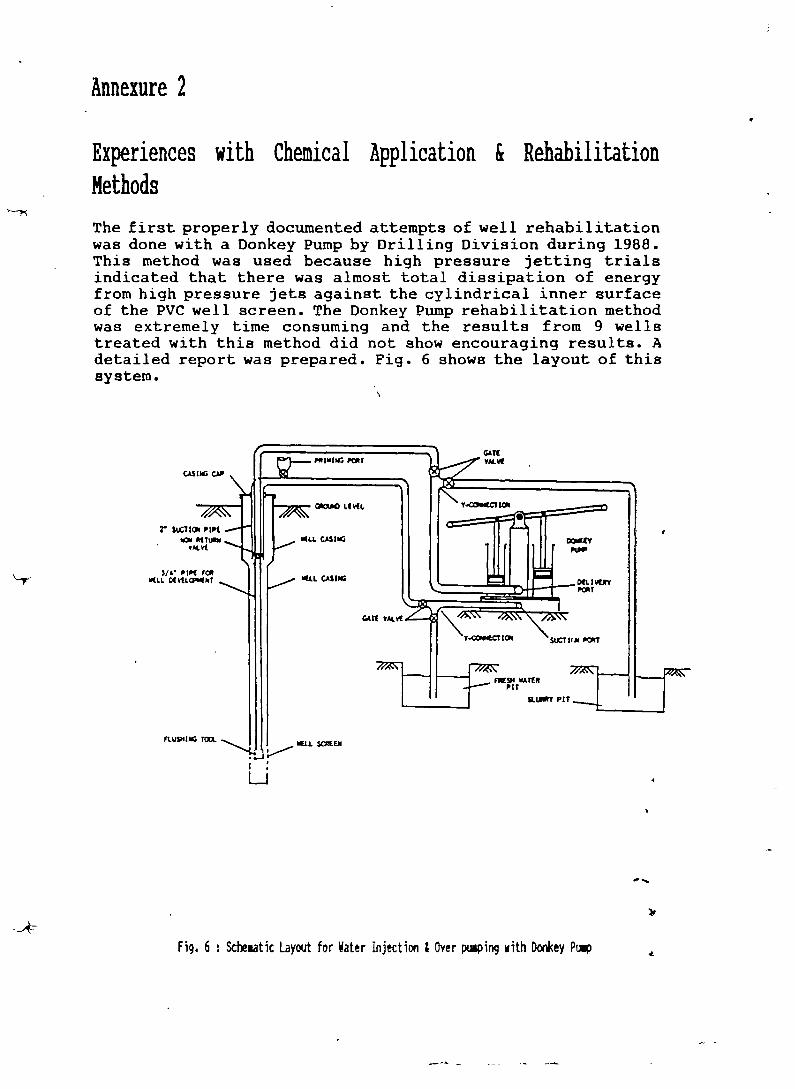
Experiences with Cheniical Application & RehabilitationMethods
The first properly documented attempts of well rehabilitationwas done with a Donkey Pump by Drilling Division during 1988.This method was used because high pressure jetting trialsindicated that there was almost total dissipation of energyfrom high pressure jets against the cylindrical inner surfaceof the PVC well screen. The Donkey Pump rehabilitation methodwas extremely time consuming and the results from 9 wellstreated with this method did not show encouraging results. Adetailed report was prepared. Fig. 6 shows the layout of thissystem.
3.
CASHS CAP
G&TtYM.V~
Wu. CASIIG
~/4• IIP( r~W(~.L~(vtL~k1 ~LL CASUG
FLU9II~ 101 ~LL S~EM
Li
ai~ PZT
Fig. 6 : Stheiatic Layout for Water Injection & Over pulping with Do*ey Pt~p


Compressors were used during 1989—90 to push chemical intothe formation around the screen area. The practice was tocap the well, build up as air pressure of 4 bar over thewater column and hold this pressure for a duration of 30minutes in order to force the chemicals through the screeninto the formation. The pressure was then be released toallow water to flow back into the well. A sequence ofpressurising and decompressing the well was done at leasttwice with the intention of moving the sterilising chemicalin the formation. However, this procedure occasionally led tothe compressed air finding a leak in the casing and escapingfrom the casing, through the old drilling annulus and emergefrom under the pump platform and has now been abandoned.Figs. 7.1, 7.2 and 7.3 shows the stages of this method.
Fig. 7.3Well Cle~ing & ~Over p~ing by Air—lift
Air
Fig. 7.1P1 aceient
Fig. 7.2Pre~surising
of theiicals the Well

t

The next set of trials were during the latter part of 1989,when 50 wells were rehabilitated mainly using the air-liftingtechnique for over pumping in wells upto 100 m deep. Thesetrials indicated that this method had a high degree ofsuccess in shallower wells but showed a high degree offailure for deeper wells. A detailed report was prepared onthese trials.
During March - June 91, 47 wells in the depth range of lessthan 45 m were rehabilitated by using cleaning chemicals andthe air-lift method of well cleaning and over pumping(Figs.7.1 & 7.3), with a fair degree of success. These wellswere within the range of 45 m depth. This established theapplicability of the air-lift method of well cleaning andover-pumping in shallow wells. A detailed report on these 47wells was prepared separately.
By November 91, threeother methods of overpumping was attempted inwells around and over 100m deep. Two of the threemethods hold promise, butneed further trials.
The first method was theuse of the Tara DA pumpassembly to manually overpump the wells. In thefour wells where thismethod was tried, theinitial results have beenencouraging but the wellshad insignificantsedimentation. Furthertrails are planned, withan attempt to mechanisethe operation. Fig. 8 is aschematic illustration ofthis method.
Pitt.. Ais~ty
Tar. CyIt...r PIV...i..,t r..t lal..
I,~,r ~aii~
Lo.,r V.11 CIVIUl
V.11 5crt1
II Z 5taci
II Z P.UjtVI
~ V•I1 Cut~I
Tar. PtSt~ V14
—I
0
Fig. 8: Manual Well Cleaning &Over pulping using the Tara DAPuip coeponents


Fig. 9: ~theiaticLayout of Well Cleaning Procedure~
The second method was to use a combination of 25 mm ND PVCpipe with 8 mm ND pneumatic hose as an eductor pipe and anair-line to follow the air-line pumping principle. Twoattempts by Maintenance Division using this method producedunsatisfactory results. Field Division Bhubaneshwar has alsoreported unsatisfactory results using this method. Therefore,further trials with this air-line combination will becarefully reassessed. This method has been illustrated inFig. 9.
To Coipressor
8 ID Pii•u~atic tUber Hots
25 — ID PVC pipe
Top Casing
25 — flC pipe
— ~PIIU.ItIC400e
Secties AA
-4
— a~PvcPipe
Hose lQu,f,4to IbOit
• b.g.l.
25 — I
Sedisotedwell ocTet.are.
Sectios Ii 50 — ‘~PVC
Well C~lng
a


The third method attempted was to use a high pressurecompressor, operating at 10 bar, to air—lift directly fromthe lower well casing from depths of upto 130 m. The air liftsucceeded by starting the air discharge when the compressorhose reached 60 m to 80 m bgl, and then lowering the hosefurther to the bottom of the well. Adequate over-pumping wasachieved, but the wells were influenced by factors such aslow yield and no sedimentation in the screen segment. Sothough the initial experience has been positive, the methodneeds to be tried in high discharge wells, and in wells withblocked screens. The methods used are basically the same asthose illustrated in Figs. 7.1 & 7.3
‘4


Annexure 3
REHABILITATION BASIC DATA & WORKRECORDSUMMARY:
BASIC RECORD
1. Regn. No. :
2. Gram Panchayat - : . . .
3. Village : . . .
4. Habitation : . . .
5. Date of well dril]~ing: .
6. Depth drilled: . . . . .
7. Type of Pump installed:
Pump Condition: . . . . . . . . . . . . . . .
Pump Utilisation: . . . . . . . . . . . . .
Chemical Analysis Results: . . . . . . . .
Problem Summary: . . . . . . . . . . . . . .,
. . . . . S • S S S • S ~ • .
0~~~~
. S ~ S • S S S ~
. S S S S ~ ~ • S
• . . S ~ • S ~ S
• S ~ S S S S ~ S
• S S S S S S • S
$1.No.
Date PumpType
Remarks
6.1 .
6.2
STATUS SURVEY RESULTS
8.
9.
10.
11.

t

1
1.1
1.2
1.3
1.4
1.5
. . . .
In
Result
(Satisfactory/Unsatisfactory)
.... . •1~ •II•I~~~
... ............ I......
: Yes! No: Yes! No
Yes! No: Yes! No
15 PUlP IEIISTALL*TIII IETIILS
15.1 DaVe: . . . . . . . . .
15 . 2 W ate r 1 e ~e 1 C b . g . 1 . ) I n well
15.3 Puip Type details: . . . . . .
16 Notes on P1 atforu/Draln/etc. : . .
REHABILITATION WORKRECORDSUMMARY
WELL DETAILS:
Date of pump removal: . . . .
Well depth measured: . . . . . .
Depth measured afterinitial cleaning: . . . . . . . . . . m
Method of initial cleaning:. . . . . . . . .
Duration : . . . . . . . . . . . . hrs.!min.
CHEMICAL USED
NaOCl Ni2CO, SIPlit Kg Kg
I..,I ~ ......••...s•
..... ,.... ......,I..I.I
3
2
Si.No.
2.1
2.2
Date
.....
I..,.
S1. Date ~thod DurationNo. (hr/un)
3.1 .............. ..
3.2 ..........•... ..,..,...
3.3 ..... .. ......•.
4
4.14.24.34.4
RESULTS OF WELL CLEANING
FULL WELL DEPTH WASREACHEDYIELD WAS MORE THAN 15 LPMWATERWASCLEAR & COLOURLESSWATER WAS ODOURLESS
,* .....
.1
. .

t

1~ATERCHEMISTRY RECORD :
B lock : •...•....... G.P:
Village:............... Pi.unp Regd.No : •
TestNo.
Odo- Trueur Col-
our
Par—tic-lesj~
p11 lur-bid-ity
EC Fe~# Cl
Results froi Status Surrey Date of Observations: Field_themist:
1.
2.
3.
Post—Rehabilitation Results Date : Field Chemist:
1.
2.
3.
Post-Rehabil_itation_Results Date: Field Cheiist~
1.
2.
3.
Post-Rehabil_itatlon_Results Date: Field Chemist:
1.
2.
3.
Post-Rehabil itation Results Date: Field the.ist:
1.
2.
3.
Post-Rehabil itat ion Results Date: Field Chemist:
1.
2.
3.
Post-Rehabil itation Results Date: Field Chemist:
1.
2.
3. .
Codes:
OdourParticles
1: No Odour1: Absent
2: Rotten Egg2: Present
3: Others


I
Detailed Time Record of Redevelopment
I
SI.No.
Dare(Jiernicil Treaiment Air ptes~uxe ippLied Obscrvaüons
limeName&~JanUty
lime Record Pre3-sure
Start Stop Duration
\
-
Prcparcd by Datc~


— S.
FiELD NOTESHEETHAND PUMPREMOVALB~c~G.P., V1Ia~e,Hab.:Regn. No.:
Condition of Rods
Rod No.1
No.2
No.3
Rod No.4
Rod No.5
No.6
Rod No.7
Rod No.8
PlungerRod
Da~
Rod
Pipe
Rod
Pipe
Pipe
Pipe No.2
Pipe No.3
No.4
Pipe No.7
Pipe No.8
Cylinder —
Pipe
Noccs~
Prcparcdb~ Date:


FiELD NOTESHEErHAND PUMPREINSIALLATON
B~c~G.P., Vilage, Nab.:Regn.No.:
0 ...
.~
Date:
Pipe
Pipe No.2
Pipe No.3
Condition of Rods
Rod No.1
Pipe
Rod
Pipe No.5
Rod
Pipe No.6
Rod
Rod No.2
No.3
No.4
No.5
No.6
No.7
No.8
Pipe
Pipe No.8
Cylinder — Plunger Rod
Notcs~
Preparedby~ Datc


Annexure 4
Methodology for Data Analysis of Statu8 Survey
1 Main Parameters
1.1 Data pertinent to comprehensive classification of apump, by the extent of its ‘problem’, was collected in3 main areas :
1. Usage of the Sourç~e2. Water Chemistry o~ the Source3. Well & Installation Condition of the Source
1.2 Data on the above aspects were collected withquestionnaires, field tests and observations. For thepurpose of identifying and categorising problem pumpsthe methodology for data analysis using the three abovementioned parameters is as follows
2 Usage:
2.1 Form 2, of the Status Survey was used to collect fielddata for assessmentof usage of a source.
2.2 With reference to the total number of householdsidentified as potential users of a source, the Usageparameter for a source was categorised as follows:
Table 1 : Overall Classification of Usage
Si.No.
~OverallUsageClassification
Prel iuinary Classification
1 GOOD Used by 75% or .ore of the total nuiber ofpotential users as a drir~cingwater source.
2 POOR Used by less than 15% to iore than 50% of thetotal ritiber of potential users as a drir~¼ingwater source.
3 BAD Used by less than 50% of the total nuiber ofpotential users as a drinking water source.
2.3 The above categorisation made it possible to arri~ atan overall classification of Usage of any source intoone of the 3 main categories of ‘Good’, ‘Poor’ and‘Bad’.
T4
I
4

±
3-

3 Water Chemistry:
3.1 Form 4 of the Status Survey recorded the results offield chemical analysis results of 8 parameters, in asequence of 3 rounds of tests for each well. Theprocedure for categorising this data was based on theapplication of IS:10500-1983 which are the IndianStandards for Test Characteristics for Drinking Water.The method of categorisation of the 8 parameters, UsingIS:10500—1983 is given below
Tile 2: Application of 15:10500-1983 for Preli.inary Classification of Cheaical Tests
= -~ - --
Si.No.
Water ~ialityParaseter
Code/Value!Range
Categorisation Codes used inanalysed data
—
1
-.--
Odour
- .~-------
j-.-
None4--..-.---.--..
Good--
0
-~
H2S:2, Other:3 Bad
2 TrueColour(Ha2entklits)
---
�50’ GoodL
>50 Bad
3 Particles’None:1
--
Good--
P
-
Present:2 Bad
4 pH
>8.5 Bad (Alkaline)
A~8.5,�6.5 Good
<6.5 Bad (Acidic)—
5 Turbidity(NTU)
�25 GoodT
—-
>25 Bad—
6 TDS:(0.65xtonductivityin iicro-sie.ens)
—
�3000-~ -- ---
Good.------
E> 3000 Bad
—
1 Iron (Fe~)(in ugh)
- -~------.
------
�0.3 Good
F> 0.3 ; � 1.0 Per.issible
>1.0 Bad-- -. -- ---.. ---- .- -
8 thiorides(mug/i)
�250 Good
C>250; �1~ Periissible>1000
— — -
I
4
-U I — I.


3.2 Based upon the above preliminary classification it waspossible to classify each of the 8 parameters of WaterChemistry into 3 qualitative descriptions of Good, Poorand Bad in the following manner:
Table 3: 0~erall Classification of Water theuistry frou Prel i.inary Classification
- .- ..- -.-
Si.No.
0~erall WaterCheiistryClass if icat ion
Preliuinary Classification by 15:10500
1 GOOD All paraleters classified either as ‘Good’ or as‘Peruissible’. No paraleters with ‘Bad’classification.
2 POOR Only paraueters of Odour, Particles0 True Colour&/or Trubidity classified as ‘Bad’.
3 BAD Parapeters of IDS, Iron &/or Chlorides classifie~as ‘Bad’.
4 Well & Installation Condition:
4.1 Form 4 of the Status Survey was also used to record thephysical condition of the pump installation and recordproblems with the pump or well by classifying seven~rnainproblems into 3 categories of ‘Severe’ ‘Medium’ and‘Slight’. The seven parameters used to assess thecondition of the well or pump were as follows
- Table 4: Paraieters & Codes used of Well & Installation Condition
51. No. Well/Puip Condition Paraieter Codes used in analysed data
1 Pu.p Condition P
2 Pedestal Shaking S
3 Platfori needs Repairs R
4 Drain needs Repairs D
5 Wa~te water disposal problei W
6 Puip is Malfunctioning N
7—
Low Yield Y


4.2 The responses to the above 7 parameters could be either‘Severe’, ‘Medium’ or ‘Slight’, depending on the degreeof problem observed. The three possible responses to the7 parameters were reduced to three possible overallcategories of well & installation condition of Good,Poor and Bad by the following met’hod:
Table 5: Overall Classification of Well £ Installation Condition
Si.No.
.-~
0~era1lClassification
-——-——
Preliiinary Classification
1 GOOD All paraaeters classified as ‘Slight’ or notrecorded as a prthle., No par~eterswith‘Mediu. ‘ or ‘Severe’ classification.
2 POOR Any paraieters classified as ‘Mediua’ and‘Severe’ classification for any paraieterother than Yield and Waste Water Disposal.
3 BAD For Yield and Waste Water Disposal paraietersclassified as ‘Severe’.
-
5 Overall Categorisation:
5.1 From the above methodology it was possible to define thelevel of problems in a problem pump by using threeparameters (USAGE, CHEMISTRY, CONDITION) and byassigning them any one of three main classifications(GOOD, POOR, BAD) to the three parameters as indicatedin Tables 1, 3 and 5. This overall categorisation couldbe summarised as follows:
Table 6: Overall Categorisation Suuuary of Probleu Well Paraicters
Overall Categorisation
good Poor Bad
Si. No. Main Parateter
1 Usage(Table 1)
Used by � 75%households fordrinking
Used byTh% to � 50%
households
Used by< 50% households
2 Water Oieuistry(Table 3)
Ho paraueterclassified as‘Ead’
‘Ba& only forOdour, Particles,tolour, Turbidity
‘Bad’ classificationfor pH, IDS, Iron,thiorides
3 Well &InstallationCondition(Table 5)
Ho parameter inclassifications of‘Medium’ or‘S-evere’ problems
Any paraieter in‘Medium’ or‘Severe’ forparaleters otherthan Waste Wateror Yield
‘Severe’ forparameters of WasteWater or Yield


5.2 From Table 6, it will be evident that the 3 mainparameters could each be categorised into 3 overallcategories and this would lead to 27 parameter-categorycombinations. These 27 combinations would then representall the possible definitons of wells including theentire spectrum of problem wells.-
6 Rehabilitation Needs Assessment:
The 27 combination of parameters and theircategorisation is given in the form of a matrix in Table7 below. From this table it will then be possible toasses the rehabilitation need of each individual well ingeneral terms.
Table 7 : Generalised Rehabilitation Need Assessment
ParameterCategory
Good Poor Bad
Usage NA RA RA+FO
Water Chemistry NA Wt Wt~W~
Puip Condition NA RP WC~1R/WWA/CR+WRD FL??
Explanation of Abbreviations used in Table 7, above:
1. NA2. RA3. WC4. pp
5. RA~FO
6. WC+WR
7. WWA8. CR-’-WR
9. FL
No ActionAssessment of Reason for RejectionWell CleaningRectification or Replacement ofPumpRejection Reason Assessment +
Follow upWell Cleaning + Referral to WaterResource DivisionWaste Water Alternative necessaryComplex Rehabilitation WRDReferralFailure consideration
The above matrix will lead to the 27 combinations ofparameters and their categories. These 27 combinations aregiven in Table 8 along with the composite rehabilitation needemerging from Table 7. The example of this analysis on StatusSurvey data for 33 wells of Dera G.P, Rajriagar Block iS
herewith attached in Table 9. -

t

Seneralised Rena~i1itation Neecs basea on aifferent Parueter & ~e~~yCo~inations
P~o. Usaoe Water~.Ja1ity
Pu,~tondition
Rehazilitation Needs
1. 6ooc Good
1
Good
2. Good Good Poor j RP
3. Looa Poor Good WC
4. Poor Good Good RA
5. Good Poor Poor WC+1P
6. Poor Good Poor R.4+RP
7. Poor Poor Good RA+WC
8. Poor Poor Poor RP~+WC+~P
9. Good Good Bad ~I (CR+~)
10. Good Bad Good (WC+~)
11. Bad Good Good (RA+FO)
12. Good Poor Bad WC4~A~/~+(CRi-~)
13. Good Bad Poor (~C+~)+fiP
14. Poor Good Bad (RA+FO)4I~/ (RA+FO)+(CR+WR)
15. Poor Bad Good RA+(WC+~)
16. Bad Sooø Poor (RA+FO)+PLP
17. Bad Poor Good (RA+FO)+i(
18. I Poor Foor Bad R~+WC+-~j~/RA+WC+(CR+WF.)
19. Foor Baa Poor R-f(WCi4~)+RP
20. Bad Poor Poor (RA+FO)4~+RP
21. Good Bad Bad (WC+WR)+~iA+RN (WC+WR)+(CR+~)-?f~
22. Bad Good Bad (P~4+f0)+*.~f (P+FQ)+(CR+W~)
23. Bad Bad Good (RP4-F0)+(~+WR)
24. Poor Bad Bad RP1+(WC+~)֋.A/R~+(WC+WR)+(CR+~) -
25. j Bad Poor Bad (RA+FO)+WC+~/(RA-fFO)+WC+(C~+~)
26. Baa Bad Poor
27. I Baa Bad Bad
(RA+FO)+(~-fWR)+~F
(RA+FO)+(~C+WR)+W~/(R~+F0)+(WC+~)+(~R+~)iiH:F[~?


-4
Table ~ i Status Survey Results £ Ret~abilitation Needs — Dera G.P., Rajnagar Block-l
Si.No.
Village Acessib- Sitelilt1 ID
: Den
Drill IDStatus
Status Survey Results Rehab
Date Depth Date lype Usage WaterChemistry
PumpCondtion
Block Rajnagar, G.P.
-
1 BADHI liv 02 11/11/88 200.00 16/12/88 IN!! Good Bad Bad (WC~WR1~WWA/tCR+WR)e RA
2 CHINCHIRI liv 01 09/02/89 194.00 14/11/88 INtl Good Bad Poor (WC~R)~RP
3 DERA HY 01 09/01/90 117.00 27/09188 IN!! Good Bad Poor LWC.WRJ.RP
4 DERA 02 13/12/89 202.31) 01/12/88 SI. Good Bad Good (WC+WRJ
5 DERA 03 03/10/90 19L30 30/04/89 IN!! Good Bad Good (WC4WRJ
6 NI00EIGAR}I HV 01 10/09/88 190.00 17/11/88 IN!! Good Bad Bad (Wt~WRJ~WWA/[CR.WRJ. RA
7 DHOBEIGARH • 50 IN!! NOIR Good Bad Bad [WC3WRJ#VWA/[CR~WRP RA
8 GAMASIKHARA IN 50 11111 NOIR Good Bad Poor (WC+WRJ~RP
9 GOKHANI IV 01 — 05/07/88 178.00 29/10/87 IN!! Good Poor Good WC
10 &OKHANI 02 12/02/90 186.30 16/11/88 IN!!
-
Good Bad Poor (WC4WR)4RP
11 GOMHAMI 03 13/10/89 171.00 19/12/88 IN!! Good Bad Poor [WC4WRI4RP
12 HATIMA HY 01 09/01/90 194.30 28/09/88 St Good Poor Good Wt
13 HATINA 02 10/02/89 195.30 27/10/88 IN!! Poor Bad Bad RA~IWt4WR)~WWA/[CR4WR)
14 HATINA 03 09/08/88 196.30 28/10188 IHU Good Bad Good tWC#WR)
15 HATJNA 04 12/03/89 193.00 25/11/88 SI. Good Bad Good [WC4WRJ
16 HAT!MA -_05 14/06/89 196.30 29/12/88 St Good Bad Poor (WC.WRI4RP

4

4
Table 9 (Contd.) Status Survey Results & Rehabilitation Needs - Dera G.P., Rajnagar Block
Si. Village~.
-
Acessib-ility
SiteID
Drilling IDStatus
Status Survey Results Rehab
~~
Date Depth Date lype Usage WaterChemistry
PumpCondtion
17 JUNUPANGARA HV 01 09/10/89 148.30 30/09/88 IMII Good Bad Poor [Wt~WR)+RP
18 JUNUPANGARA 50 IN!! NOIR Bad Good Good (RA~F0J
19 KAITHA LV 01 10/07/88 204.00 15/11188 IN!! Good Bad Good [WC4WR)
20 KAITHA 02 10/01/88 204.30
-
14/11/88 IN!! Good
-
Bad Poor (WC’WRJ~RP
21 KAITHA 03 10/01/88 200.30 15/11/88 IN!! Good Bad Good IWC+VR)
22 KAITHA 04 09/03/90 200.00 23/11/89 SI. Good Bad Good (WCeWRJ
23 KAUHA 50 IN!! NWR Good Poor Bad WCê WWA/1CR~WR)
24 KATHAPANGARA MB 01 11/03/89 114.00 21/12/88 IN!! - Good Bad Good (WC.WRJ
25 KAIHAPANGARA 50 IN!! NOIR Bad Good Good [RA~FD)
26 KATHUAGANDA IV 01 12/06/89 196.00 27/12/88 IN!! Good Bad Poor tWC’WRl~RP
27 KATHUAGANDA 02 10/06/89 289.00 26/12/88 IN!! Good Bad Good [WC~WRj
28 LUNIA FT 01 01/12/89 184.30 19/01/89 !NI! Good Bad Good (WC+WRJ
29 MUGAXAHI IN 01 12/06/90 196.30 18/11/88 INII Good Bad Good IWt~WR)
30 NIJAGAK LV 01 IN!! NOIR Good Bad Poor (WC+WRJ~RP
31 NUAGAN 02 12/07/88 209.00 28/12/88 IN!! Poor Bad Good RA4IWt4WR]
32 PARIPANGARA NB 01 10/05/88 195.00 03/09/89 1$!! Good Bad Good [Wt~WRJ
33 PARIPANGARA 02 10/03/88 184.30 30/10/88 INhI Good Bad Good (WC~WR)

t

Annexure 5
Well DevelopmentMethods& Well andPumpMiiintennnceandReh~bilitRtionfrom “GroundWaterandWells”, SecondEdition, by FletcherG. Driscoll, publishedby Johnson’sFiltrationSystemsInc. USA.
2. IS: 11632- 1986, Tndinn Standardfor CodeofPracticeof Rehabilitationof Tubewells,publishedby Bureauof Indian Standards,NewDelhi.
3. IS: 10500- 1983, Tndi~rnStandardfor TestCharacteristicsfor Drinking Water,pubIi~hedbyBureauof Indian Standards,NewDelhi.
-t

-fr

GroundwaterWells
Second Editionf nroundwaterand‘~“hensivestudy treat,A comp1~ ~ to locate,eA~the techno~giesu ttlis resource.
Production well
Observationwell ‘- ~
— - A ~- ~ ~~il ~ ~ . ~I~I ~: :~~~-I ~ ~:~ •~ -.- ..~. , - .-
•.Drawdo~a~~ ~:.•
Pvmpngwater~~ ~
—-_~~4~
A— •iI~~ I-I ~j..
~ ~ —
~ ~-~- ~raye~ -~ -We~screen -


502
1
CHAPTER15
Developmentof WaterWells
~~ELI.DEVELOPMENTMETHODSDifTcrcnt ~cll development procedures have evol’.ed in different regions because
of the ph.sical charactcristics ofaquifcrs and the typc of drilling rig used to drill thc~cll. Unfortunately, some dc%clopmcnt techniques are still used in situations v.hcreother, more rcccntly developed procedures would produce better results. Nc~de.~c!opmenttechniques. especially those using compressed air, should be consideredb~contractors hcn they buy and equip a nc~rig. Any development procedure shouldbe able to clean the well so that sand concentration in the water is below the maximumallowable limit set for the particular water use.
O~erpumping
The simplest method of remo’ing lines from water-bearing formations is b~o~erpurt~ping.that is. pumping at a higher rate than the well will be pumped t~henput into service. This procedure has some merit. because any nell that can bepumped sand free at a high rate can be pumped sand free at a lov~er rate.
Overpumping. by itself. seldom produces an efficcnt ~el! or full stabilization ofthe aquifer. particularly in unconsolidated sediments, because most of the de~elop-ment action takes place in the most permeable zones closest to the top of the sct,een.For a gi~enpumping rate. the longer the screen, the less development ~villtake placein the loner part of the screen. After fine material h~sbeen removed from the pcrrrie-able zones near the top of the screen. water entering the screen moves preferentiallythrough these de~eloped zones. ka~ingthe rest of the ~elI poorl) developed andcontributine onl~’small volumes of water to the total yield. In some cases. over-pumping ma) compact finer sediments around the borehole and thereby resipçt t1o~~into the screen. If more powerful agitation is not performed. an inefficier.t nell ma)

IXVELOPME’~TOF ‘.‘-‘sTER WELLS 503
result.On the other hand, overpumpingmay be effectivein filter-packedwells incompetent,relatively non-stratifiedsand- -Bridgestoneformationsbecauseflow towardthewell boreis moreor less uniform.
There is anotherobjection to over-pumping that is commonlyoverlooked.
- Waterflows in only onedirection,toward
the screen,andsomesandgrains may be (J Ileft in a bridgedcondition, resulting in aformation that is only partially stabilized(Figure 15.4). If this conditionexistsandthe formation is agitateddunngnormalpumpcyclesafter thewell hasbeencorn-pleted.sedimentmayenterthewell if thesand bridges become unstable and
L_Well screencollapse. __________________________________
Dnliers ordinarily use a test pumpfor },g.rr 15.4. During drbeiopm~n!b> c~~rpur~pin~.
overnumping operations, but v.hcn a ~an4grains c-,~nbridge opcni~g~b~cju~1k’. o.- Cu?S In ~nI) one direction. Once the i~c-U i~piicrd
largequanhit) of u-atcr mustbe pumped, ~ ~ agitation b~nurmai pump c~ciin~
it may be difficult to obtain equipment break ‘~nthe b’udge~.c~u~ing%and pumpirI~.
of sufficient capacityat reasonablecost.Thcrefor~,the pumpingequipmentintendedfor regularwell use is sometimesusedfor o~crpumpingDependingon the type of pump, this may be done eitherb~op.cratingthe pumpat a higherspeedor h~allowing thepumpto dischargeat the surf.iccat a lov.cr-than.normaloperatingpressure.Thereis oneseriousobjectionto perform-ing this ~i-orkwith the permanentpump. Sand pumping will subject the pump toexcessive v.car, which over time can reduceits operatingetTicicnc). Under sc~crcconditions,the pumpmay becomesand locked,eitherduringpumping or after shutoff. Shouldsandlocking occur.thepumpmustbe pulled,disassembled.clcancd.andrepairedif ncccssar~beforebeing placed backinto service.
Backi’iashing
Effectivedevelopmentproceduresshouldcause reversalsofflow throughthescreenopeningsth2t will agitatethe sediment.removethe finer fraction,and then rearrange
the remainingformationparticles(Figure 15.5). Reversingthedirectionofflo~breaksdown the bridging betweenlarge particlesand acrossscreenopeningsthat results‘i-hcn the water flows in only one direction.The backflowportion of a backwashingcycle breaksdown bridging, andthe inflow then moves the fine materialtoward thescreenand into the ~vell,
A surgingactionconsistsof alternatel)lifting a column of water a significantdis-tanceabovethe pumpingwater level and letting the water fall back into the neIl.This processis calledrawhiding. Before beginningthe surging oper’tion. the pumpshould be startedat reducedcapacity and gradually increasedto full capacit’ tominimize thedangerof sand-lockingthepump.In the rawhiding procedure. thepumpis started. andassoonas ~~ter is lifted to the surfacethe pump15 shut off: thewaterin the pump cohimn pipe then falls back into the well. The pump is startedand

(~ROI,~FI~~TriS
‘1
4
Figure iS.S. Efkciiie dc~eiopment action requires mo%emrnl 01 iiaier in both direction.. tbrou~h screen0penw~.Reier..ing flo,~help, break doi~nbrid~in~of p~r1icIc-s.Moicmrnt in oni) ant dirc’cuon. asi~hc’~pa~pi~gfrom the neiL dot’s not produce the propci’ dcaeiopmcnt effccf.
stoppedas rapidly as the power unit and startingequipment~ill permit. To avoiddamagingthc pump. thc control box should be equippedwith a starterlockout sothat the pumpcannotbe startedwhen it is back spinning.During the proccdurc,thcwell shouldhe pumpedto wasteoccasionallyto removethesandthat hasbeen broughtin ~‘ythe surgingaction.
Some~cll~ respondsatisfactorilyto ra~hiding.but in manycasesthe surgingeffectis not ‘-Igorous enough to obtain maximum results.As in the case of ovcrpumping.the surgingeffectsmay be concentratedonlync~rthe top of thescrccnor in themostpermeablezones.Thus. the lower part of a long screenma)’ remain relativelyunde’-eloped.
Although o’ crpumpingandbackwash1ngtechniquesarcusedwidely, andin certainsituationsmay producereasonableresults.their overalleffectivenessin high-capacity~ells is relati~el~limited v.hencomparedwith other developmentmethods.Othermetnods.as describedbelow,arecapableof removingmore fine materialsin lesstimeandgenerally can producehigherspecific capacities.
MechanicalSurging
AnOthermethodof developmentis to force waterto flow into and out of a screenby operatinga plungerup and down in the casIng,similar to a piston in a cylinderThe tool normally usedis calleda surgeblock, surgeplunger,or swab(Figure 15.6)A hearsbailer may be used to producethe surgingaction,but it is not as effectiveas the close-fitting surgeblock. Although somedrillers dependon surgeblocks for
developingscreenedwells, othersfeel that this device is not effectiveandthat it may,in somecases,evenbe detrimentalbecauseit forces fine materialback into the for-mation beforethe fines can be removedfrom the well, To minimize this problem,fine material shouldbe removedfrom the boreholeas often as possible.
Beforestarting to surge,the well should be bailed to makesurethat waterwill flowinto it. Lower the surgeblock into the well until it is 10 to 15 ft (3 to 4.6 m) beneath
-WetIscreen

DCVLLOPMENTOF WATER WEl 13 505
fl ,,—Drdl stem oi’
dnlI pipe
_ ±F1~tt,~?t “flt~
~ leMel~’
L: rds~JblocK~
-- ~
-~ - -,.rWeH screen -
-. t~-’Sançi~iM~ilI
— —- A Inwater —
Figure 1ST. For certain t)pes of formations. asurge block is an efleetbe tool for nell deselop-ment. On the doi~nstroke.nter is Iorctd oun’ardinto the fonnatiorc siater, silt, and fine sand arethen polled into the ~e1l screen during theupstroke.
I-
P~pe7the static water level, but above thescreen or packer (Figure 15.7). The watercolumn will effectively transmit the ac-tion of the block to the screen section.The initial surging motion should be rel-atively gentle, allowing any materialblocking the screen to break up, go intosuspension, and then move into the well.The surge block (or bailer) should be op-erated with particular care if the forma-tion above the screen consists mainly offine sand, silt, or soft clay which may
t
FIgure 15.6. T~plealsurge block eon~isttng of taoleather or rubberdnri nnd’sichrtj bet—ten threesteelor sioodendiscs. ‘the blocksare constructedso that the outside diameter of the rubber lips isequal to the Inside dtameter of the screen.The solidpart tif the block Is I in (25 4 mm) smaller in d’~ameter titan the scrt~n.
slump into the screen. As water begins to
move casil) both into and out of thescreen. the surging tool is usuaIl~ loweredin steps to just ztbote the screen. As theblock is lowered, the force of the surgingmovement is increased. In a wellequipped with a long screen. it ma~pro’emore effective to operate the suite blockin the screen to concentrate its action atvarious levels. De’elopment should be-gin above the screen and mo’.e progres-sivelydownward to pre’ mt the tool frombecoming sand locked.
The force exerted on the formation de-pends on the length of the stroke and thevertical velocity of the suite block. For acable tool rig, length of the stroke is de-termined b~the spudding motion: the~erttcal velocit~depends on the weightexerted on the block and the retraction

lv~
H~J l)~rIII
I
c,ROL’~[)”;TER
speed.A block mustbe weightedso that it will fali at the desired ratewhen use’i ~~itha cable tool rig. Dunngretractionof the block.co~iuriue thespuddingmotion toa~oids.2nd locking the block in the casing. If a rotary rig is being used,the ~cight on theblock is prov~dedby the drill pipe. The speedof retraction and length of pull arcgo’ernedb~the physical characteristicsof’ the rig.
Continuesurging for several minutes. then pull the block from the ~~ell.Air maybe usedto blow the sedimentout of the well if de~clopmcntis done‘~itha rotar~ng or if an air compressoris available.Sedimentcan be removedby a hailer or sandpumpwhena cable tool rig is used.The surgingaction is concentratedat the top ofthe screen,and this effect is accentuatedif the lowerpart of the screenis continually’blocked off by the sandbrought in by ihe de~elopmentprocess.In general,devel-
opmerit can be accelerated if the amount of sediment in the screen is kept to aminimum.A sumpor length ofcasinginstalledbeneaththescreenis helpful in keepingthe screenfree of sediment.Continuesurgingandcleaninguntil little or no sand canbe pulled into the ~vcll.Total developmenttime may range from about2 hoursfor
small ~clls to many days for largewells ~iih long screens.Occasionally,surgingmay causeupwardmovementof wateroutsidethe ~~cllcasing
if the v.ashingaction disrupts the sealaroundthe casingformed by the overly-ing sediments.\~‘hcnthis occurs,usc ofthe surgeblock must bc discontinuedorsedimentfrom the overlying materialsmay iri’adc the screenedzone.
Surge blocks sometimesproduce un.satisfactory resultsin certainformations,especially ~~hcnthe aquifer containsmans clay streaks.becausethe action ofthe block can caus.c clay’ to plug the for-mation. When this happensa reductionin yield uccurs.rather than an increase.
Surgeblocks arealso less usefulwhentheparticlesmakingup the formationarcan-gular. becauseangularparticles do notsort themselvesas readily as roundedgrains. In addition, if large amountsofmica are presentin the aquifer, the flator tabolar mica flakes canclog the outersurfaceof thescreenandthezonearoundthescreenby aligning themselvesperpen-dicularto the directionof flow. Cloggingb~mica canbe minimized lithe surgingproceduresarc applied rather gently tothesell. It is good practiceto avoidover-
developmentwhen mica is presentin theaquifer.
Oneothertype of surging tool is calleda swab.The simplesttype of swab,a rub-
Hauling cable
~,—Swabflange
art— ~ij~ _ag
Figure 15J. Lioe swabbing is used primariiy inconsolidated sq~i1ers.As the ~i~abis puiled upwardat about 3 It/,.ec (0.9 rn/see), high-pressure con-ditions at the top or the s’~ibforce water Into theformalion. Low-pressure conditions at the basecause now of sand. silt, and ‘iater back into theborehole.

DEvELoPMENTorWATER WELLS 507
ber-flangedmud scow or bailer, is low- . ~
ercd into the casingto any selectedpoin: ~ ‘‘
below thewaterlevel and thenpulled up-v~’ardat about 3 ft/sec (0.9 m/scc), with -S.: \‘no attemptto reversethe flow andcausea surgingeffect (Figure 15.8). Thelength 1:~’.~of the s~abbingstroke is usually much .‘.~
‘longer than in surging.As the scow is t:: ~raised,high pressureis creatednear thetop of the sco~v~hichdn~es~ater intothe formation.Water is dravnback into “.~. ~
the nell beneaththe s~abbecausethepressureis lower. The scowusually hasa :.~. ~
‘~al~eat the bottom v~hch opensto in - ‘
creasethe fall rate in the borehole.Thismethod of swabbing.called line swab- — ‘•~‘ .
bing. ic often used to clean fine material Figure iS.9. When a doubit—flangrd swab is used,waler is pumped Into the Iorm.atiun b4-twrrn lht
from deep~cUs drilled in consolidated flanges. Flow reenters thc borchol~ iboir or b-dowrock aquifers.Swabbing screenedv.~Ils the swab. During pumping. thr swib is raised and
lowered o~crshort dittaners,requiresspecialprecautions,hou~cvcr.Intight (Ioss-permcabilit~)formations. for example,swabbingcan result in collapsedscreens. and great care must be taken to insurethat the hydraulicconductivity of theformation is capableof yielding sufficient water to keeppressurediflerentialss~ithinreasonablelimits. A’.oid sv~abbing~clls that haveplastic casingor screensS~liandsilly sandformationsin v~hichscreen-slotsi~csarcabout0.010in (0.25mrn)orsmallerare particularly troublesome,and use of a swab in this caseshould be n~oidcd
A more cffecti~ c ss~ahhingdevice is shown in ligure 15.9. \Vith this tool. sater~pumpedinto the formationbctssecnt~soflangesand returnsto the ~cll boreeither
aho’.e or below the flanges.During pumping. the swabis raisedand lo’crcd in theboreholeover short distances.Sometimesa bypasstube is installed in the double-flanged sssahto facilitate the movementof ~atcr up the boreholefrom beloss thetool. The advantageof a double-flangedswab is that the energy’ of the waler beingpumpedinto the tool can be directed at selectedpartsof the formation.
In summary.surgeblocks are inexpensivetools that are convenientto use and.within their limitations, do an effectivejob. The) can be adaptedfor useon many’typesof r.gsand usedin combinationwith otherdevelopmentmethods.In addition.surgebiocks can be used for wells of any diameteror depth.Surging proceduresproducegood results for screeninstallationsin zonesha~inggood porosityand hy-
draulic conductivity.
Air Deseloping by Surgingand Pumping
Many drillers use compressedair to de~elopwells in consolidatedand unconsol-idatedformations.Thepracticeofaltematelvsurgingand pumpingwith air hastro~vn
with the greatincreasein the numberof rotarydrilling ngsequipped~ ith large aircompressors.In air surging.air is injectedinto the well to lift the “ater to the surface.As it reachesthe top of the casing. the air supply is shut ofT. allowing the aeratedwater column to fall. Air-lift pumpingis usedto pumpthev.ell penodicallsto remove

SOS \t)\’-~TER~\t)\~EL~.
sedimentfrom the screenor boreholc.and is accom~Lishedhs installing art air lineinsidean cductorpipe in the ~‘cII. Eductorsystemsaic generally requiredfor larg’_diameter~sclls.~shenlimited ‘olumes of air are a~a~able.or when the static waterlevel is loss in relation to the ~sclldepth Most rotar’ n~s.hos~ever,havesuflicientair capacitsto use theeasingas theeductorfor 6-to !2-in (152- to 305-mm)diameter~sells.Figure 15.lOa shov-s the basiclasout of an air-lift systemand the appropriateterms.
The uphole ‘elocities required to remo’ecuttings and water in air dnlling werediscussedin ChapterII. Uphole~eIocitiesof 3.000to 5.000ft/mm (915 to 1.520m/mm)are neededfor dry-air dnlltng wherelittle or no ~sateris entenngthe borehole.For remo’ing large~olumesof ~atcr andcuttings.a surfactantis mixed into a smallvolume of~~aterand thenaddedto theairsiream.The surfactantbreaksup the ~atermasses so they canbe lifted to the surfaceat a rather low velocity [50 to 200 ft/mm(15.2 to 61 mimi)]. thereby reducingair-volume requirements.During air devel-opment.hov-evcr.surfactantsare usedonly ~hen compressorcapacityis insufficientto lift ~satcrto thesurface.Therefore,thecontractormustmaintain upholevclocitiesin the range of 1.000 to 2.500 ft/mm (305 to 762 m~min)to achieve a reasonabledischarge.
Generally,it is not possible to predict ~shatuphole velocity is actually neededbecauseof submergencefactors(discussedlater),total pumpinglift requirements.and
w!!”~”.~
—�Oj~~~
crpe
y ,
5-,— -— ~
7ot~
- G’p,r~
-Cas~IA
A I
I,,,
r Burlap
Educlor
I I
IILDisc~rge
a b
Figure i5.IOi. This diagram shows common terms applied to air-lift pumping. (!ngc’rsoll.Rand. 197!)1S.lOb. In this installation, the top of the well Is plug~edduring the air-lift with burlap and siips todirect Ibe water to the outlet pipe.

509
~
Fi~urc 15.11. Thr tspe ot discharge produced from a well during air de~elopmeni depends on thy airsolumr asaiiabk. total tilL submergence, and annular area. in practice. two diflerrrii flow condiiions canbe recognized when air is used for water well deieiopmenL although other flow regimes mas rsisi atmuch b—er or higher selocities in sm~Iler diameter pipes Rdentifled bs Taiicl and Dukier (19S0) andHestroni (t9g)~ This diagram pro’Ide’s a qualiuii~eillustration of how muliiphase flow (,watcr and air)occurs in the casing during air deieIopmenm. The percent submergence, total lilt., and capacin of thecompressor wili control the reiati~eproportion of air and water for a particular well Griffith (198-i)points oui some of the e’srreme difficulties in making a rigorous anus sis of multiphase 55 stems, (a)introduction of a small ‘olume of air under a high head causes little changr in the water lesel in thewell, in this case. th~air pressure asailable is just sufficient to olercome the initial head esened bs thewaler column. (b) .As air solume increases. thc water column becomes pants aerated. Displacement a!the water b~the air causes the water column to rise in the casing, Drawdown does not change becauserio pumping is oecurriig. (c) Further incre~sesin air ‘iolume cause aerated slugs of water to b.c liftedIrregu[arl~ out the top cif th~casing. Between surge’s. the water ksei in the casing falls to near the stiticleiei. (dl If enough air is asailablc. aerated water will conitnuatis flow out the top ol the well \\ ithaseinge submcrgence and total lift, the solume of air ~ersoswater is about iO to I. Hiuher air ~uotumesmas incresse the pumping ratt somewhat. but still higher rates ma’ aclualls reduce thc flow rue becausrflow into th~well is impeded b~e~ce’ssi~eair solume.
DEVELOPMEN1OF V.ATER WELLS
the non-predictable way water will enter the borehole. For example, if water entersasahigh-volume,concentratedflow at a discretepoint(coarsegravellayeror fracture),the uphole velocity requiredat that point will be quite largeso the water masscanbe brokenup efficiently. On theotherhand,if wateris seeping evenly into the boreholeover its entirelength, the uphoic velocity requirement is less because the force (ve-locity) needed to lift the fine water droplets is less. Thus, it is virtually impossibletopredictbeforehandthe upholevelocitiesrequiredfor air developmentproceduresInpractice. the contractorignoresuphol~velocity considerationsand concentratesonthe air ~olumc neededto lift the water adequately Fortunately,researchon deter-mining the air volume requiredto lift a certain volume at a specifiedsubmergenceand total pumping lift has been done. This information, presented later in this chapter,gives the contractor the ability to predict the volume of air that must be availabletoproducean adequatedischargefor certain downholeconditions.
Staticwater Clevel .‘ C ‘~ ~
-,-‘~j ~:D~
Cas:ng ‘
~:!~
Air line ‘~. ;
a
a b”-” ~‘.~::::: ci
I
‘I. -Li’—

(~R(~L\t)\5~TLR~\t~’5t
Both air prcssurc and air ‘olumc arc important in :nitiatin~ and maintaining anatr surtingor air-lift pumpingoperation.For t~picalheadconditionsfound in bore-holes 300 to 400 ft (91.5 to 122 m) deep, the compressorused for the air suppl~should be capable of developing a minimum pressure of r25 psi (862 kPa). This isenough pressure to overcome the initial head created ~. the submergence of the airline. This head is called the starting submergence. Once the pressure initiates ~the air capacity (volume) becomes the most importar.i factor in successful air-lift.
‘.5 ~‘‘‘i. ___
3 __ _
I ~ 25._:~~’ ___
0
I ~ ~ ____
~, --~-“-r
I 1.5 Chdrtgc.
verticalI ~ 1 Oscale,
C.’
U.
0 75
o 50
0 25
0
3
—--.‘—--
Total pumping lift, ft
Figure 15.12. Cubic feet o(air required to pump I gpm (53 m’fda~)for ‘arious submergence’s and pumpingtilts. The raiIu-s shown here between air ~olurneand water pumped are predicated on using the propersize e’ducior and casing (see Table 15.1). Field experience suggests that these air requirements ma) beopiimisuc in practice, somewhat more air will be required thin iod~te’d.(Ingcrsol[’Rand. 1971)

DEVLLDP~’.EV101 WATER WILLS 511
pumping.Figure 15.11 illustrateshow the additionof different volumesof air affectsthe water in the borehole.A useful rule of thumb for determiningthe propercom-pressorcapacityfor air-lift pumping is to provideabout ~ cfm (0.0004mt/scc)of airfor each I gpm (5.5 m’/day) of water at the anticipatedpumping rate. In practice,a375-cfm (0.2-rn‘/sec)compressorcanusually pump400 to 500 gpm (2,180 to 2,730rn’/da~)v.ith proper pumpingsubmergenceof the air line.
The ~olume of air required to operatean air-lift efficiently dependson the totalpumpinglift, the pumpingsubmergence,and the areaof the annulusbetweeneductorand casing(Figure 15.12). To calculatepumpingsubmergence,the length of air linebeloss thepumpingwater level is divided b~’the total length of air line suspendedinthe ssell. For wells with about 10010 200 ft (30.5 to 61 m) of total pumpinglift, air-lift pumpingis quite efficient when the air linc is submergedabout60 percentof itstotal length duringpumping(60-percentpumpingsubmergence)(Figure 15.13) \\‘henthe total pumping lift exceeds200 ft. the pumping submergencema~have to bedecreasedso that the start-uppressureat the bottom of the air line doesnot exceedthe pressurecapacityof the compressor.Good results can be obtainedby’ a skillfulopcri:orwhile ytumping with a pumpingsubmergenceas loss as 30 percen: In somecasc~acceptableresultshavebeenobtainedwith a pumpingsubmergenceas low as10 pc’rcent The air line shouldnot be placcd all the way to thc bottom of the wcllv~hcnpumping begins,unlessrequired for propersubmergence.becausethc air mustthen o’crcornean unnecessarilyhigh prcssurc’hcad,
The volume of air necdedto lift water also dependson sshctherintermittcnl or
stcad~flow is required. For developmentssork. it is not ncccssar~to m:iiniain asteady discharge.and. in fact, somesurgingof the air lift is beni.’l~cial,If sleadshotsmust lx maintained(pumpingtests, for e~amplc).the air-volumerequirementsv.illusually lx greaterthan thosegivenin Figure 15.12. Fordeephorcholess~ith loss staticwaler let els. the actualvolume of air requiredmay be two to threetimesthe solumc
shossnin Figure 15.12 to maintain steadyflow.
C.Li __________C., _____________ _______________________________________________ci ____ _____ ______________________LI
C,ciE ______________________________________________ ___________________
Li
U)
Tota’ pumpinglift. ft
40 I
‘
‘~ -
~
300 100 200 300 400 500 600 700 eoo 900
Figure 15.13. Appro~im3icpe’rceni pumping submergenct’ for optimum air-lilt efliciencs, In general,dr~elopmcni procr
1~d~m’i..t efficieniI~ when th~discharge is mas.imiied. iherelore. th~submcrieiic-rshould alwass b~’as gre-it as possiblc within prscti~—.al limii’.. ,I’~rso/I-R..’—.~1c1

51 GROU\D\~~ ss ELLS
Figure IS.IOa shotssthe propermethodof placing the eductor pipe and air line inthe ssell A tee at the top of the eductor
pipe is fitted ssiiha dischargepipe at theside outlet. A bushingwith the insidecpeninglarge enoughto clear the cou-plingsof the air line is connectedto thetopof the tee. Burlap or similar materialwrapped around the air line just abovethe tee. and held b~slips, reducesspray-ing aroundthe topof thewell andenablesmore accurateyield measurementsdur-ing pumping(Figure 15,lOb).
Table IS. I lists therecommendedsizesof educiorpipe and air line for ‘iir-liftpumping, Some sariation from theseSizes may be necessaryfor practical rea-sons, but the combinationsshossngen-crall~gRe good results.
DesigningAir-Lift PumpingOperation
Somedrillers andwell constructionen.gincersdo not take thc time to analyzethe operationalcharacteristicsof an airlift, This practicecan lead to inefficientpumping, lost time, and, in somecases.failure to pumpany- water.The examplecited bclov. illustratesthe factors thatshouldhe consideredfor designinga sue-ccssful air-lift pumpingoperation.
PompingRue’Size of SSeii Casing
if E4ucior Pipe is Lw’d
Size of Educiur Pipe(or casing if no ~linirnuriSize
educlor pipe i~used) of Air Lime•1,4•, — I is .r. I. •
301o 60 16410 32760 to 80 327 to 43680 to 100 436 to 545
10010 ISO 545io 818iso to 250 818 to 1.360250 to 400 1.360 to 2.180400 to 700 2.180 to 3,820700 io 1.000 3.820 to 5.450
1.000 to 1.5(X) 5.450 to 8.180
4 102. or Larr,ei’5 127, or lar~cr6 152. or larger6 152.oriarge’r8 203.or larger8 203. or larger
10 25.4, or larger12 305. or Lirger16 4C6, or Larger
2 5!3 763½ 894 025 1276 1528 203
10 25412 305
“~ 13I 25I 25I,. 32l’/ 382 513 643 644 102
,iciuol pwnping rote is dependent on percent suhmergrr.ce.
1~1
0 ft _~ ~ - —Eductorpipe
—~-~‘z.—~~ ‘....e-Z. “-.
~—Casing
._100 ft —
\\ /
200tt_____‘ I
~~Air line360 ft__
Well screen
395 ft_,,,,~400 ft —~
405 ft ________
Figure i5.14. Determining the design of an air’Illtc~s(cmfor a specific wdl.
A boreholeis completedto a depthof 405 ft and screened from 360 to 405 ft (FigureIS 14) A 10-in diametercasingis selectedto minimize friction lossesand provideadequateclearancefor the pumpbossls,Staticwater level is at 100 ft. Examinationof the cuttings suggeststhat a specific capacitY of 6 gpm/ft of drawdowri can beobtained.It is decidedto air-lift pumpat a rate of 600 gpm, 20 percentabovethe
Table 15.1. RecommendedPipeSizes for Air-Lift Pumping

DL’ ELOPMES’T OF WATEP. WELLS 513
- designrateof 500 gpm. Thus, the pumping water level would be at 200 ft. From thisinformation, it is possibleto selectthe propersize equipmentfor theair lift and toestimatethe potential efficiency of the system.Severalstepsshould be followed intheanalysis:
1 Determinethe diameterof the eductorpipe(if required)and the air ‘ine. Table15.1 shossisthat an 8-in eductorand a 3-in air line shouldbe usedfor the lU-in casingA smallerdiametereductormight be chosen,butthe air-pressurerequirementstou!drise significantly becauseof the additional fnctiori effects.
2. Determinethe lengthsof the eductorpipe andthe air line. In this instance,theair line v~iII always stay inside the eductorpipe.The bottom of the eductorpipe isset at 400 ft, with the air lIne set at 395 ft. The 400—ft submergencedepthis selectedso that the lower end of the eductorpipe is set at a reasonabledistanceabovethebottomof the screen.
3 Determinesubmergence:4.
% pumpingsubmergence t~th of air line bclov. pumpinv wate-rIctel - IOUtotal length of air line
195—
395
— 50%
Expenence suggests that the air lift will be reasonablyefficient at this pumpingsub-mergence:that is. the volume of water pumped per cubic foot of air is acceptable(Figure 15.13). Ideally, pumpingsubmergenceshouldbe as greataspossible.hut maybe limited by- initial aIr-pressurerequirementsas shown in step5.
4 Determineair-volumercqutrcmcnts.For a total pump~riglift of 200 ft. Figure15.12shows that I cfm is required to pump I gpm Thus. 600 cfm arc required topumpat 600 gpm.
5. Determine shethcr the compressor has sufficient pressure to initiate floss- in theair line.
~slinimum psi requirement~. Icn~thof air line — static tsatcrlet-el
2.31
395— lOU= 2.31
128 psi
Thus.at least 128 psi will be needed to start the air lift for the startingsubmergenceselected(a safet~factor of 25 percent is usually addedto this pressurefigure). .Asdrass down develops, the psi requirement drops substantially because the head acli~gon the air line decreases.
Properanalysisof the factorsaffectingtheair lift providessomeassurancethat theair-lift developmentproceduresstill function as desired.But the designof an air-liftsystemandthedeterminationoutsoperationalcharacteristicsare notmathematicallyprecise.Therefore,the performanceobtainedfrom a particularair-lift design may bemoreor less thananticipated.Thus.the contractoror engineermustbe preparedtomakeappropriateadjustments.In general.air-lift pumpingwill bemostefficient whenthe static ssaterlevel is high. the cas:rigdiameteris relatively small. a~dthe ‘e:ldepthis not e\cessivein relation to thepressurecapability’ of the compr~ssor.

)13 GROUNI)\\;TER t—~D\5ELLS
Air Deselopment ProceduresAir development procedures should begin by determiningthat groundwatercan
flow freel~into the screen.Application of too muchair volumein the boreholetshenthe formation is clogged can result in a collapsedscreen.To’ minimize the initialpumpingrate, the air line and cductor (if used)can be placed at a rather shallowsubmergence.At this setting,even the introductionof largeair volumeswill produceonly a moderatepumpingrateand.therefore.will placeonly low collapsepressureson the tsell screen.Introductionof small air volumesat greatersubmergencealsostillproduceloss ~ields.
Once uninhibited flow into the screenhas beenestablished,the eductorpipe (if
used) is lossercdto within 5 ft (1.5 m) of the bottom of the screen,assumingthatsufficient pressureis available to overcomethe static head. Developmentcan alsostart near the top of the screen,dependingon the preferenceof the driller. The airline is placed so that its lower end is up inside the eductorpipe at th~propersub-mergencelet el. Beforeblowinganywateror drilling fluid outofthetscll with asuddenlarge injection of air, the air lift shouldbe operatedto pumpfluids at a reducedratefrom the ts~ll
Air is released into the line and the ts-clI is pumpeduntil the wateris virtually sandfrec. The sakeat the air tank outlet is then closed. allossing the pressure in the tankto build. The actualpressurerequired will dependon the starting submergence;43psi (296 kPa) is needed for each IOU ft (30.5 m) of starting submergence. In themeantime, the air linc is lowered so that its lower end is I ft or so beloss’ the cductor
~ ‘lo initiate surging. the s-alt-c is openedquickly to allow air from the tank torush ~uddenfyinto the ‘sell. Thistendstodrite the ~~ateroutssardthroughthe ts-cllscreenopenings.Ordinarily, a brief butforceful head of ssater‘sill also overflowor shootfrom the casingandcductorpipeat the ground surface(Figure 15.15).Wheti the air line ~spulled up into theeductorpipe after the first chargeof air
hasbeenreleasedinto the ‘sell, theair lift‘sill again pump.thusreversingthe flow(v.ater flosss into thewell) andcompletingthesurging cycle.
Th~‘sell is pumped until the waterclearsup. and then another“head” of airis releasedssith the air line set below theeductorpipe.To resumepumping.theairline is again lifted. Surgingcyclesarc re-peateduntil thewater is relatis-ely-free ofsandor other fine particlesimmediatelyafter the screenhasreceivedan air blast.This indicatesthat developmentis ap-proachingcompletion in the region nearthe bottom of the eductorpipe.The air-lift assemblyis then raisedto a position
- . ~ -~,*rr
‘.4 .,.,. - ar-, ~ -~:~-~“ ~
-.‘ - ~ -;.-‘,, ..~, ~~ ~ ~
Figure 15.15. D_’ring air.IiIt de~eiopment. brief butpos~erfuispurts of ssater ~iIl be ejected from thetop of thc caslnt,. (rest Drilling Sen 1ce3)
I — I I-

DEVELOPMENT OF WATEP WELLS 515
about5 ft (1.5 m) higherandthesameoperationsarc repeated.In this way, the entirescreenis developedin S-ft inters’als.From time to time, the air lift shouldbe loweredto its original position near the bottom of the well and operated as a pumpto cleanout any sand that has accumulatedinsidethe screen.
Severalalternativesurging proceduresarc available In onemethod,the air line isalwaysretainedwithin the eductorpipe.Surgingis accomplishedby- letting the watercolumn in the eductorpipe fall periodically.The ‘sell is then air-lift pumped untilthe waler becomesclear.This cycle is repeatedat different levels in the ‘s-elI screenuntil the well is developed.In anothermethod,the air line is usedin the casingandthe well casingactsas the eductorpipe.The surging cycle is the sameas describedabove.
Somedrillers use an isolatedair lift to removesedimentmore effectively from theaquifer. Flangedgasketsare mountedon the top and bottom of the isolation tool(Figure 15.16).The gasketsshouldbe snug fitting, but still allots some sedimenttomove around them so that sand locking does not occur. After the screenhas beencleanedout initially, the isolation tool is loweredto the top of the screenand theairline is set at the properdcpth. Afiei eachzone is developedh~surging and air.liuipumping, the tool is lowered to the next section Thus, the formation is developed
in separate stages.Two developmentmethods— air lift
andmechanicalsurging — arcoftcncorn-
~A.r iiri~ biiied to repair drilling damageand re-mote fine material from the formation.This combined method is particularly’
Casing I -
A i suited to reverserotary rigs equipped
I with air-lift assist. In this technique, adouble surge-blockassemblyattachedto
I the drill pipe is raisedand droppedrap-idly’ to produce the required turbulence
____________________ in and near the screen Sirriultaneousl~,water is lifted ‘sith air insidethe drill pipe
from the zone isolated by’ the tsso sur~c
I blocks Aficr the ssatcrbecomesfree ofsediment,theassemblyis lo’sercd to thenext section.This methodis especiallyef-fective in longscreensbecauseit can con-centrate thedeselopmcntenerg~on short
I sectionsof the aquifer. It is importanttostart this procedureat the top of the
I screen to avoid sand lockine the_____________ assembly-
Under sonic conditions, the aquiferI ma’- becomeair lockedtthena large burst
of air is injectedinto the sr~eenedareaofthe ssell, Ceriainkindsof formationsare
more prone ~o air locking espcciaii~thoseformatiunsthatconsisiof stratified,
7-
L
-Dnipipc
—Packer
I~I. -4£ ~ —, ,—Perfora?e~
~ c -
—
~I -
Sit~. ‘~~-a~it.1 — , i4~.,a
—
~ ~a&n;j ( r nc
- - ~ ~
at~n~i,.Lr.c., S.JC‘C
Figure 15.i6, Isoi3tion tools ire used no focus theeflCrg~of air bursts on a sp~’ci1icpart of th~aquiferand to remo~esediment b% air Lifting

I
516 GROI. Nt)tstTL}~t\D”ELL’~
coarsesandor gra’el lensesseparatedb~thin, impermeableclay lay ers.Aquifers‘stibgood ‘ct-nealh~draulicconductivityaregenerallynotaffecjcd.Surgingwith airusuallsdoesnot leadto air locking. If someair becomestrappedin the aquifer,however jj
may impedethe flow of statertoss-ardthe screen.In formations susceptibleto airlocking. sureingwith air shouldbe avoided.Otherproceduressuchas high-seIocit~jetting with stater or air may be more suitablein formationstshereair trapping is aproblem.
High-Velocity Jetting
Developmentby’ high-velocity- jetting may- be done with either water or air, Inpractice,jetting with ‘sater is almost alssaysaccompaniedby simultaneousair-liftpumpingso that clogging of the formation doesnot occur. This dual processis de-scnbedlater in this sectionand is one of the most effective methodsof ‘sell desel-oprnent.The jetting procedureconsistsof operating a honzontalwaterjet insidethe‘sell screenso that high-s-elocitystreamsof watershootout throughthe screenopen-ings. Jettingis particularly- successfulin des-elopinghighly stratified, unconsolidatedformations.
The equipmentrequired for jet developmentincludes a jetting tool ‘sith t’s-o ormoreequally spacednozzles,high-pressurepump, high-pressurehoseand connec-tions,stringof pipe,andwater tank or otherwatersupply.The high-velocityjets force‘sanerthrough the screenopenings.agitatingand rearrangingthe particlesof the for-mation surroundingthe screen.The filter c~kcdepositedon the boreholein conven-tional rotary drilling is effectively brokendown and dispersedso the drilling fluidthat haspenetratedthe formation can be pumpedout. Jetting‘sill also help correctdamageto the formation’sporosity and pcrmcabilty resultingfrom drilling
Figure 15.17shot;$ ajettingtool ‘sith four nozzles.Nozzlesshouldhespacedequallyaround the circumferenceof thejetting tool to hydraulicaly-balancethe tool duringoperation:for example,four noulcs shouldbe spaced90 degreesapart. Best resultsarc obtainedif the nozzlesarc designedfor maximum hydraulicefliciency.but hor-izontal holes drilled in a plugged pipe or coupling ‘sill be reasonablyeffcctisc, The
~ c~
~ Nozzle
- CheckValve
Figurei5.17. Four-nozjiejeiiing tooi desizned for jet developmentof ~eII screens.Thecheck~jive ~iio~isihe jetting to~iito be u~.dfur iniermintecl pumping of the ~seii.A plate bottom is often us-ed in piace ofthe check saiie if ihe iooi IS not to be us-ed for pumpi~x.To ayoi-d breakage, the pipe base of the io-oicm be made of hesn-’.ali pipe ~f lilt is be attached to the borlom of thedrill pipe. At right. a jettingtool is being lo~.ertd into inner casing t~.3Lbaa b-ceo centered in the surface easing.

DEVEWF’MENI OF WATER WELLS 517
jetting tool shouldbe constructedso that the nozzle outletsor holesarc as close tothe inside diameter of the screen as practical [generallyless than 1 in (25.4 mm)].
In manyjetting operations,watercontainingsedimentis recirculatedthroughthejetting tool, therebycausingerosionof the nozzleboresand a pronouncedpressure
reductionat thenozzle face. Erosionof the nozzleboresmay’ be a significant problerr~if the nozzlesareconstructedof mild steel.Therefore,all nozzlesshouldbeconstructedfrom stainlesssteel pipe or other abrasion-resistant material. High concentrations ofsediment can also damage screens if the jets are directed at one area for long periods.Thus,every’ effon shouldbe madeto limit sedimentconcentrationin water used forjetting.
The lowest nozzle velocity for effective jetting is considered to be about 100 ft/sec(30.5 rn/see). Much better results can be expected when the nozzle velocities are I SC)to 300 ft/sec (45.7 to 91.5 rn/see). Velocitieshigher than 300 ft/secmay not result insufficient additional benefit to justify the added cost. In fact, velocities obtained byusingpressureshigher thanabout400 psi (2,760 kPa)at the nozzle may cause abrasion.dependingon the screenmaterial, the distancebetweenthe nozzleand screenbody.and the amount 01 sedimentcarried in or entrainedby’ the jetting water. In ger.eral.
200 psi (l,3S0 kPa) at the nozzle is the preferred operating pressure for metallicscreens.Great caremust be exercisedin jetting screensconstructedof PVC or otherlessabrasion’reststantmaterials.All jettingof PVC screensshouldbe doneonly ssiihclean water to minimize abrasion,and the pressureshould not exceed100 psi (690kPa). Table 15.2 provides data for nozzlesof several sizesat different operatingpress ures.
The pipe that attaches to the jetting tool shouldbe largeenoughto minim~zcfrictionlosses so that velocity at the nozzle is as high as possihlc.Sizcs generally’ used arcgiven in Table 15.3.
Jettingcanbe accomplishedwith virtually any drilling rig, but it is moreconten-icntly- done with rotary’ rigs becausethe mudpumpcansupply’ the requireddossnholcpressure. \\‘hen using a rotary’ rig, the jetting tool is attachedto the lo’serend of thedrill string and rotation is controlledby the rig The jetting tool is placed near thebottom of the screenandrotatedslowly ‘shilc being pulledupwardat 5 to 15 rninutcspcr foot of screen.dependingon the natureof the fcrmzition. Material looscredfror~tthe formation accumulatesat the bottom of the screenas the jetting tool is raisedslowly. Thismaterialis removedlaterby air-lift pumpingor bailing. By slossly rotatingthe jetting tool and g.radually raising it. the entiresurfaceof the screenis exposedto
the vigorous action of the jets. Several passes are made up thescreenuntil theamountof additional material removed from the formation becomes negligible. To avoiderosionof the screenand to expeditedevelopmenLthejetting tool shouldneter be
Table 15.2. Approximate Jet \‘elocirt and Dischargeper Nozzle
~ I’,.-..,- \.uk ~ ‘-..~k~ ~ ~ - ~‘W~ P”~s.p~’ICI p.,I~WkI’.I I~Op’-I II ~ ~P~I ~‘ p.. ELy-a Li~I ~S.)p-s.,I ‘~êIPSI ~,i ~ IPS’
~ I~Jnr~,-,, ~ ~ “.~.,,‘ ‘ II..fl-.’~p ‘.I..,’’ L)’.~I~u.- % .~‘,‘ I’,.. ~— —— ft., — , I,., — g.,, (p. a * ~e — o. It. — S , p~ — .1’ Ii’, ei~ cpa — 4*’ (P. — ‘ “a — C,’’
.~ i1Y’ 3.~’’ .U iy ~i-~ ~,1 ~ I3~ .i~ i~ C~ 133 4’) 1,1 I - i’~i ~‘ ‘‘
4 :~ ‘—‘ t” s: i~ 3-i.b is ‘S - i-ic’ ~ :i ti3 t~ 473’ .i 131 - i’C~ 31‘13 IC~ ‘.~$ ‘~-) I” i.’O tc.t. -ii ~3 I4~I -i2’ 3~. t~ I3~ 4’) 35 ~‘1 I ~‘Q ~Is —
I l~‘ i~5 ~-‘ ‘- ~,. ~-‘ 14. b ‘~ ~ (4 ~ ‘~.4 .1’~ I” -l~5 ‘.-i ~‘I. i~ ‘I - -.
‘-‘-ta. — ,‘e—,. - -:: c r,-1,.~’c, ç._rr ,~n’~,n.Pr—I,-I-. ~ L’ r. r~?rc’ I.. .‘. 05 ra’- frI -, -. z.’lIfl a.. 1PC .1’ P l’~’.-‘ Lj”.. “S ~‘~,“s’ -.-—_~ it.-. rt,.-”tc,,s’..-, ‘S ~i d.’,~JtyI”’,-.n
t a., ..‘flWo I,?’

5lS ,kII~ \i~~~1L~~
operatedin a stationar’ position.in general, the effectivenessofthe jetting process is controlled by the open area
and slot confkuration of the screenand the thoroughnessof thejetting operation.The screenshould I-ia~eas much open areaas possible.aiid the openin~sshould beevenl~distributedaroundthe circumferenceof the screen.Theseconditior,spermitthe jettingaction to reacha high percentageof the formationaroundthe screen.Theconfigurationofscreenopeningscaneitherenhanceor retardthe velocity of thewaterasit passes through the screen (Figure 15.18). High-velocity’ jetting works effectivelythroughV-shapedopeningsin continuous-slotscreens,but it is lessuseful in punchedor louteredpipe sshereslot configurationimpedesaccessto the formation.
Optimal remo~alof sedimentb~Jetting~sill dependon the time allotted to theprocessBecausethe jetting energy can focus on only a small pan of the formationat a given moment, more time may- be necessary’than for other methodsthat affecta larger portion of the formation.Lecs satisfactort’ resultsfrom jetting almost inev-ttably occursshen not enoughtime is alloss-ed for a thoroughjob.
Jettingwith Air
Jetting s~ith air is an alternative to waterjetting In areas~sheressatcr is not readily-asuilable. air Jetting is art c~trcmely practical procedure that produces goüd resultsin bothconsolidatedand unconsolidatedformations.Its userequiresless set-up timebecause, in most cases, air has already- been used to drill the borehole. In addition.jetting ssith air initiatesair-lift pumping.sshichhelpsremovesedimentfrom thesscll.Casingsize and air-line submergencewill affect the efficiency-of air-lift pumping.Themain disad’.antagcof air jelttng is that many rigs are equipped sssth compressorsha~ing limited pressurecap~bilitics,,\ 125-psi (862.kPa)compressor,for cs,implc,canoperateonl~at starting heads that arc less thanabout 285 ft (86.9m). Furthermore.the pressurenear thebottom of the well may- be so greatthat.evenif the compressorcan pump air, the actualcompressed(air) volume is so small that the amount ofturbulencegeneratedmay- not be sufficient to dc”elop the ~selIcff~cti%-clyat thatpoint. In ccrta;n localities, howctcr. additional high-pressure. high-volumeair corn-
Table 15.3. ~IinimumSize of Pipe Required to hold Friction Losses to a Total ofApprot.im~tel~ 20 It (6.J m) of head
PumpingRaic
~pm m’/d-.i’
Pipc~Length100 Ii
(30.5 m)200 Ii(6i i-nt
400 ft(122 i-n)
600 Ii(183 m~
in mm in mm I in mm in mm
35 19150 - 27375 409
100 545150 818200 1.090250 1,360300 1.640350 1,910400 2.l80
1½ 38li.’~ 382 512 512½ 643 763 763 764 102
4 102
1½ 382 51
- 2 512½ 643 763 764 1024 1024 1024 102
2 512 SI2½ 643 764 1024 1024 1024 1025 1275 l27
2 512½ 643 763 764 1024 1025 1275 1275 1275 127
I

DEVEWPME~”Tor V.ATER WEU.~S 519
press.orscan be rented to help in the developmentprocessThe methodologyusedin airjettingis thesame as that used in waterjetting. Because
- air is a compressiblefluid, however, it is not possibleto specify- anticipatednozzlevelocities; the actual (compressed)volume of air emitted from thejetting tool willbe controlled by- the head of water in the casing (see Chapter Il). Ordinarily, thecompressorcapacity of typical rotary rigs is sufficient to create enough air to jet
‘effectively in wells 150 to 300 ft (45.7 to 91.5 m) deep. For water well v.ork, thenozzlesizesfor an air-jelling tool areapproximately’thesame size as thosefor a v.ater-jetting tool.
In formationssusceptibleto air locking. an air-jetting tool with small holesdrilledin the bottom should be usedto developthe formation. Air coming out the bottomofthis special jetting tool enhancesthe efficiencyof the air lift, thereby’ entrainingwater, sedimentdislodgedby the jets, and air that could become trappedin theadjacent sediments. The tool can be pulled up periodicallywithin thecasingandused
~1 ~
Continuous-slotscreen
Slottedpipe Louvered screen
Fi~ur~i5.IS. The openareior tI’c screen and th~conligur-ation o! theslot operiuni~sare impor-iani Factors
cuniro!I,m~the eflectjieness oF deselopment procr~ure~UsIfl~~5*~tCrjVtling. -

52C GROU\D”~TER;~t)\~ELL’,
solely as acon~entionalair-lift device. --
in conclusion,developmentby’ jetting offers severalad~antages.Ener2v15 concen-trated a’erasmallareawith greateffectiveness,everypart of thescreencanbecoveredselecti’elv.andi~is rclative1~’simpleto applyand is not likely’ to causetrouble fromo~erapplication.Althoughwater jetting imparts a more po~~erfulforce into the for-mationcomparedwith air jetting. an air lift usuallyoccursduring air jetting whichassuresthat fines will be drawnoutof the formation efficiently-. In water~etung.“ateris being added to the formation so that fine material may not move into the screenquiteas readily.
High-\’eIocit~\Vater JettingCombinedwith SimultaneousPumping
Although water jetting proceduresare e~trcmelveffective in dislodging materialfrom the formation,maximumdevelopmentefficiency isachieved~hcn water~jettin~proceduresare combinedwith simultaneousair-lift pumpingor otherpumpingmeth-ods (Figure 15.19). Thiscombinationof developmenttechniquesis particularl~su~--cessfi~!fur ~clls in unconsolidatedsandsandgravels.In waterjetting. ~atcr is addedto thc ~i’ll at a rate governed by’ the nozzlc size and the pump pressure The ~olurncof~aterpumpedfrom the ~l.cllshouldal~aysc~cccdthe volume pumpedin durinrjettir.~ because sediment removal is greatly’ enhancedwith higher discharge.Thus.the wa~crlc’cl in the well still be kept below static level and somewater ~‘~illmo’c
continuously-from theformation into thewell screenasthe work proceeds. The stcad~movementof waler into the well helpsremo’ c some of the suspendedmaterial-
loosenedby’ the jetting operation.The airlift then pumps the sedimentfrom the~‘.cllbeforc it can settle in the screen
Table 15.1 lists the air-line diametersrecommendedto pump certain ‘olumesof v,atcr.Occasionally,the size of the air
line may ha’c to be decreasedsomcshatso that it fits into the annulus bet’~eenthe Jetting pipe and the casing. Anotheraltcrnati~eis to decreasethe size of thejetting pipe.The air-lift systemoperates
best ~hen the bottom of the air line is
placedjust abovethejetting tool. becausemoresuspendedsedimentwill be carriedup the borehole.When usinghigh-veloc-ity’ jetting procedures, de’elopment
- shouldstart at the bottomof the screen.Thejettingwater is usuallycleanwater
hauledto thedrill site. In instanceswheresufficient water suppliesare unavailable.thecontractormay usethewaterpumped
from the well, To avoid damagingthehigh-pressurepump, jetting nozzles,and
screen,however, the fine sand pumped
- ,,,_GroutA
Wetscreen
pack
Figure 15.19. The jetting tool acid drop pipe aresep2ralc from the air line so that jetting and air-lift pun~plngcan be done simultarieousi).

4’ DEVLLDPME~-TOF W-STEP.WLLLS 521
from the well should be settled out in a tank or settling pit before this water isrecirculated.To enhancethe deselopmcntprocess,chemicalssuchas polvphosphaicsare often added to thejetting water to help break.upclays..
Whenair-lift pumpingis impractical,a submersiblepumpearl be usedduringjet-ting. Usually’ the pumpmustbe placed well abovethejetting tool so that the amountof sand passingthrough the pump is minimized. Thus, the pump causesmaterialtemporarily placed in suspensionby- the jetting action to move into the screen, but
much of the materialfalls to thebottom.This sedimentmustbe removedpcriodicall~during the jetting and pumpingoperationso the entirescreenis developed.
A COMPARISON OFTHREEDEVELOPMENTMETHODS
Certait development methods exertmorepowerful cleaning forces on the formation
thando others,andthus arebetterable to removethe dnlling fluid andcreatea zoneof high porosity’ and hy-draulic conductivity-aroundthe screen.Resultsfrom an e~-perimentalwell field at the lmgation ResearchCenterat Staples.Minnesotadem-onstratethe relativedifferencesin threedevelopmentmethodsTen irrigation wellswere constructedat Staplesin surficial glacial outwash, using three types of ‘tellscreensThis site ssaschosenbecauseof the highly uniform nature of the aquifer AUwells s~cre drilled by the direct rotary drilling method.Two dificrent .lrilling flui~!additi~cs~sercused— bentonitc and polymer. After well corisiructioti. each screenwasdc~elop~din threestages,first by- oserpumping.secondh~rnech~ritcalsurging.and third by- waterjetting andsimultaneousair-lift pumping Eachdeselopmentmethodwas continueduntil the water was essentiallysandfree. A 24-hourpumpingtestsasconductedaftereachof the threedc~cloprncntcptsodes.data“crc acquired.analyzed. and stored with the aid of a computersystem.The Staplesin~cstiptioni~oneof the few scientific studiesconductedin a uniform aquifer that exaniinesman~
of the sscll constructionand completion I ______________________________
variablesthat affect development. I
Resultsof the study- show that the as’-crage specific capacitiesof the ~clls 20drilled with bentoniteintpro~cd74 per-cent ~hcn o~crpumping “as followed t3 6succcssi’cly by mechanicalsurging and 11 ~
simultaneous~atcrjcttingjair-liut pump- Iing (Figure 15.20). Drawdown datasug- 10 78gest over-pumping is the least dTecti’c of Ithese three development methods.whereassimultaneouswater jettingjair- -
lift pumpingremovedsedimentanddrill-ing fluid that the other development 0 After —
methods could not dislodge. In general. over-test datafrom Staplessho’s thatthee~en- pumptnQtual specific capacity ofa ~selldepends to
Figure 15.20.Aierage specific capIriite~ of ‘~etlsdrilled ~~ith bentonite. after ~arious deielopmentmethods.1ndi~iduatsp-cnflc capacities ~ere rn~.sure-d when no more sediment could b~diclod~e-dfrom the formation b’ a particular de~eIopmenimethod.fIt er-ncr c’: ai’ - :-~u
After Aftersurgina jer.’rg
a great extent on ~~hatde~elopmentmethod is used.
As suggestedearlier in this chapter,theimprovement in specific capacity

GRIH. \I)’~TER;\I)’SELLS
achie~~db~an’ aeveloprnent method may be seriously retarded because of limiz~dopen~irca.For the wells drilled with hentonitc.those completed“ith screensha~ingmore than 15 percent open area had 52 percentgreaterspecificcapacitiesthan thosecompleted~~ithscreenshavingless than 15 percent open area (Figure 15.21). As theopenareaof the screenis increased,the enhancedefiecti~-enessof the de~elopmentcausesa correspondingincreasein specificcapacity.
The specific capacityof a ~~ellis alsoa function of’~hichdrilling fluid is selectedForeachdevelopmentepisode,~~ellsdrilled ‘sith polymera’era~cd56 percenthigherspecific capacitiesthan did the ~ells drilled with bentonite(Figure 11.21.page362)(\\ er-ncrat al.. 19S0).This differenceoccursbecausesome of the bentonitepenetratesfartherinto the formationduring the drilling processthan any’ developmer.tmethod
can reach.On theotherhand,polymeric drilling fluids beyondthe reachofa de~cl-opmcnt methodsimply- break down naturally- over time and thus offer no resistanceto flow.
USE OF POLVPIIOSPI IATES IN DE~’ELOPMENT
Adding a small amount of a poly phosphate before or during’ de~clupnienthelpsconsidcrabl~in rcmo~ing clays that occur naturally in the aquifer and those claysintroducedinto the borcholcas partof the drilling fluid Poly-phosphatesdispersethi-cia’ particlesin the formationso they canbe rcmo’cd.Enough time mustbe allos~cd
bcts~ccn introduction of the poly phosphate and development, usually- overnight, sothe clay massesbecome completely-disaggregated15cc Chapter Il), After the poly-phosphatesolution is jetted or surgedinto the screen.water should be addedto thc“dl io dri’ t’ the solution farther into thc formation.
T~otypesof poly phosphatesa-cusedin well dcselopmcnt— crystalline and glass~.Cr~stalline pol’.phosphatcc that help remove clays from the aquifer arc sodium acidpyrophosphate(SAPP). tetrasodiump’rophosphate(TSPP).and sodium tripoly-
phosphate(STP).Sodiumhcxamctaphos-phatc(SHMF’) is a glassy phosphatethatis readily availableand thereforeoftenused in de’ eloping ‘sells. About 15 lb (6.8kg)alapal’ phosphateshouldbe usedforeach 100 gal (0.4 m’) of water in thescreen. T~opounds (0.9 kg) of sodiumhypochlorite(3 to IS percentchlorineso-lution) alsoshould be addedto every 100gal ofssaterin the ~cll to control bacterialgrowth promoted by- the presenceofpolyphosphates.
Polyphosphates should be premixed151 2-~a.-~ ist ~ ,~ beforeintroductioninto the well because
they do not mix easily’ ssith cold water.Deve’opmentstageOccasionally the mix water is heatedto
Figure 15.21.Open are-aof the ~ieil 5cr-i-encontrokthe effe-cü~enessof ‘arjou% deieiopmentmethods help dissolve the chemical. In general. thcfor ~iclIsdrilled ‘~iibbeniontie. In general, de~el- lighter the density,the morequickly- theopment is moct die-chit ,~henthescreenopen area
is the large-si.(It CTfCr- er ci,. 1980, Driscoll Cr ~ polyphosphatewill go into solution. So-19~Uai dium inpoly-phosphate,for example,~s
I

DEVELOPMENT OF WATER WELLS 523
available in three densities, lithe polyphosphate is jettcd, some contraclors usc asolution with twice the recommendedconcentration.A largeramount of polyphos-phate,hossever,doesnot give significantly- betterresultswhenused for drilling fluid
- dispersion and, under certain conditions,may- causeseriousproblems.Care must be exercisedif SHMPis usedbecause the phosphate can become glassy
in the ~el1 under certainconditions,causingsevereplugging of the formation andscreen.For example,an over-richsolutionofSHMPcan precipitateglassy-phosphateson contactwith thecoldgroundwaterfoundtypically in northernEuropeandsouthernCanada.Theseglassyprecipitatesarc gelatinousmassesthat are extremelydifficultto removebecauseno eilectis-esolventsexist. Acids will breakdown the glassy- con-dition eventually,but the time requiredis impracticalfor efficient nell deselopment.Therefore,gIassy~phosphatesshould neverbe dumpedundissolvedinto a well Theuse of a glassy phosphatealsocan be undesirablein certain formations Althoughlittle is knossn about the e’act chemicalconditionstha! may causethe phosphatetobecomesemisolid in a borchole,experiencehasshown that the useof SH~1Pcan hea problem in glauconitic sandstones. SUMPis available in p:te form, cru~’cd, or asa po’sder, ss’hich afl’ects the density- of the product.
The additionof sscttingagentsto polyphosphateswill increasetheir cfkctis-encssin disaggregating clays. One pound (0.5 kg) of wetting agcnt (for example. PluronicF-68) is added to 100 gal (0.4 r&) of polyphr~ephatc solution \Vetttng agents andpol~phosphatesshouldnot be usedin formations~ith thinly beddedclays and sands.hccauscthe~cchemicalstend to make the clay’s nearthe horcho!eunsuhir,causingthem to mi~ ith the sand.The hydraulicconductivityof theaquifer neartheboreholeis then reducedand clay continually passesinto the boreholeduring eachpurnpIn~

(~ROt\1~’5~7IR \\F)’5111S
CHADTER19
\\Tell and PumpMaintenanceandRehabilitation
rehabilitation is definedas restoringa ~cU to its mostefficient condition ~‘aria_s treatments or reconstruction methods. The necessity for ~clI rch.1bllit:iL”;~ssilj c:~cndon thc cfTcctiscncssof the maintenance program and hoss i~iu~k i,
hasts’r foiTo~cd,In some cases,a major reconstructionof the sseil ni:iy he nccess~such ~i rcphicing the screenor lining a p’~rtion of the casing 1 intdy niaintcna~desig-:d to o~ercornespecific problemscan sustain ‘sell perforrnaiic. thcreh~ r-lonp- ~ ‘sdl life
EfIr:~iscmaintenar.ccrrogramsbegin ssith ssellconstructinnrecordsci-.o’sinr ~-~-
logic c.nd.:ions. ‘sater quality and numping performance. especially specific capJrA carc:_ stud’ ci theopeatinghistory’ of other‘sells in the local regionshouldsug~-~logica s~ers for des ising rtiain:cnancc schedules o~rehabilitation rroccdurcs So m:---s’aria~s arc in’ ol’ ed. ho’sc’ yr. that a single maintenance progrz..n cannot be des is-a
that ‘.s~,,‘so-l. for cs-cry h’d~ogcologic condition and c’.cry- type of sscll.lns~:t.on and routine maintenance schedules must be estaolishcd on the basis -f
the in:.. idua! cnaractcrist~:sof the well and pump. It is important to take noteany chaz~csin the operatingcharacteristicsof the well and pump. becauseboth c~ridetenr~-ateto the point ‘shererehabilitationis difficult, if not impossible.Expene:cindica~-
2that if the specific capacityof a well declinesby 25 percent,it is time ‘~initiate rehabilitation procedures.Further neglect increasescosts for mainteriazesigni 1ic~~ly-
To de:ermineany loss in perfo- mancc,somereferencemark “.ill be needed.?~r-
formar.:~ standardsarcestablishedby conductinga pumpingtestas part of the cc~-pletion of escry- new ‘sell The data from this tc~tshouldbe given to the owner .ritheforr cIa ssrittcnreport.Thiswill allow thewell ownerto monitor-ti pcrforma—:cof the ~lto detectany dropin yield. Thesedataalsoguidea rehabilitationcontrac~rin devis:~gan appropriaterehabilitation procedure.A form listing the imporz~tinforrna~..onto be retaincdat the well site is in the pocketof this book.
Lossola major watcrsupply,eventemporarily, is intolerablein many- cases.Tht~:-fore, ongoingperformanceevaluationof the well is mandatoryif well failures arc~o
I1I

WELL fi”.D P12.11’ M~!~A~CEA~’[) REHAI1ILIT AliCr. 631
be avoided.The checklistbelow can be used to evaluatethe performanceof a ‘scll
• What is the staticwater level in the productionwelI’~• What is the pumpingrateafter a specified periodof continuouspumping’• What is thepumping‘sater level aftera specifiedperiodofcontinuouspumpin~’• ~rhat is the specific capacity-aftera specifiedperiod of continuouspumping”• \\‘hat is thesandcontentin a v.atersampleaftera specifiedperiodof continuous
pumping?• What is the total depth of the well?• What is the efficienc~’of the well?• What is thenormalpumpingrateandhowmany- hoursper daydoesit operate’~• What hasbeenthe generaltrend in ssaterlcselsin wells in the area?• How muchdrawdosvnis createdin the production‘sell becauseof pumpingof
nearbywells?
A significant changein any of the first 7 conditionslisted aboveindicatesthat a ‘sellor pumpis in needof attention.For instance,a decline in the specificcapacit~mightindicate plugging of the screen-slot openings.
Onceinspectionprocedureshavebeenestablished,they shouldbe fullosscd in cvcr~
subsequentinspection.The pumping icsts, for example.shüuld he rur, for the samelength of time at the samerate, and havethe samepcriod of recoscr~Local ‘sell’drilling or pump-maintenancecontractorsarc helpful in cstabltshingprocedures.andsometimesoffer maintenancecontracts.These,r1dis-idualsretain recordsof all mainS
tcnanectheyperform andpros-idcv.-rittcn reportsto thessellossner A tsp~’~ilpLinip,n~(aquifer) testdata form that can be used for maintenance esalu.itto’ ,s in the pu~k~-~of this hook.
After the pumping.ti.’st data havebeen recorded,they canh5’ s’omr.ircd ~sith theoriginal numbersandan esaluationmaderegardingany decline in t!-.c ‘sell’s perlol-
mancc since the last surs-cy. Storage of ss-ell rccords can he i.Kilitatci~ us the use ofcomputers.For relatively loss cost,complete‘sell recordscan he maintainedthat canhelp forecast ‘shen maintenanceandrehabilitation ssork stjnulj h~en~ertaken.
Table 19.1 lists the most prcs’alcnt ‘sell problems occurring in ‘ar~oust\pcs of
aquifersandthe t’pical maintenancefrequencyrequired.The maintc~.ancefiguresinTable19. I arebasedon wellsconstructedto locally acceptabledesiinar,dconstructionstandardsin the United Statesthat may not be consistentssith the r’cst n’atcrialsor
methodsavailable,Therefore. althoughthescmaintenanceschedulesare realistic inlight of the materialsand constructionmethodsused,thc~prooabl’ indicategreaterfrequenciesthan ‘sould be anticipatedif the best technology “crc used
MAJOR CAUSESOF DETERIORATING WELL PERFOR’slA\CE
Fis-c major problemsoccur s’ith ~veIlsover time. The first ins ol’.es a reductionir.the ‘sell ~ield. \Vell yield i-na’ be reducedby’ chemical incrustationer hiofouling ofthe ‘sell screenand the formation materialsaroundthe intake port:on of the ‘sell,Deterioratingscreenand formationconditionscanbe alleviatedh~t~emaintenanceprocedures discussed beloss. Of course.other en’. ironmenial factors eiti-icr naturalor manmade,ma’ lead to reducedyields, but correctionof thesecon.!itionsma~bedifficult or imposs~blcbecauseof political, engineering,or naturalconstraints Fore~arnplc.a genera!drop in the svatertable causedmainly by shcri- or long-term

i’rU~1.\1~\’.\TLR \\:~
ciima:ic trcni±s ii reduce‘sell icid. as ‘sill in:erlcrerice from nearb~‘.sdfl~, Also.the pumpinglesel may droposertime in ssellspumpe.~continuously‘shenth~transrnissisit~ of tl-c aquifer limits the amount of “ater that can reach the ‘sells esen
Major Mainienanci~
.Aquifer Type Most Pres~Ient \~ellProblem~ Frt-quenr~Requirement(Municipal) I
Allus ial Silt, clas, sand intrusion: iron 2-5 yearsprecipitation:incrustationofscreens.biologic fouling: limiiedrecharge: casing failure
Sandstone Fissureplugging: easingfailure.sandproduction:corrosion
6-10 years
LimL’stonL’ Fissurepluggingh~clay, silt, and 6-12 yearscarbonatescale
Basaltic l:isus Fissureandscsicleplugging by 6.72 yearsclay andsilt: somescale ‘
deposition I
lnlcrbed~led Loss initial ields. plugging isf 3.7 y carss~int’tuncand
shale
,I~luifLrb~ hiy .i nU tilt: fissureplugging:limited rech~irgc:casing
Metamorphic
failure
Loss- initial ‘teld. fissure plugging 12-15 yearsh~silt arid clay-: mineraliiationofrissures p
Consolidatedsedimentary
Fissurepluggingby iron and 6-~yearsotherminerals:losv to medium
:
Semiconsolidated
iniu~lyield
Clay. silt, sandintrusion: 5-8 yearsandconsolidaied incrustationof screensin sandsedimentary and grascl ‘sells: fissurepluggjng I
,
of limestoneaquifersin theinterbeddedsand.gravel, marl,clay-, silt formations:biologic
- fouling: iron precipitation•Excluding pumps and c~c)intng ~saicrtables,
Estimates of major m~i”.tcr~anccIrca’,c-’icic-s arc based on the foilo%lng assumptionsI \Scllt arcocii~pjr-p~cOntinuoijsis at ihe highest sustained rate ihe~are carsible of pl’oducinr
2 M~)ormair:cna’~e~s ~jrcd ~rici~tie sustained yield dccrrase~io 75 percent of the ~nttial ,icld3 Major rtlajntrriancc is considered to reprcseni a cosi expcndiiure ofapproximaiel~10 percent of the 10121
curmeni rcpiaccmcni co-st ~ir,or maInlc~anccis excluded.4 V elk ~rc designed ia accordance ~ currCni pracutcs. not necessarily in accord.ance ~.ih best a~2iiabk
technolo~
(After (Jass ci al.)
Table 19.1. \lust PresakntV~elI ProblemsOccurringin VariousT~pesofAquifersand the T~pleal ‘ShlintenanceFrequenc~Required
*

V.1 1 .‘.N!> 1t’.ii’ 5)~.I’ii ~\‘~( i A~—.1 P_Ili-\ilii I1~1l~.
thoughenoughwater may csist in the aquifer on a regional basis.P~uggtng of the fc~matior. around the ‘sell scrccr. by fine particles is scccin~
factor in dctcriorattng‘sell performance.Small particlesin most unconso.daicdfor-rriations arc disturbedduringpumpcycling, and ‘shile temporarily in susprrsionthe:.movegradually- tossardthe screen.This samephenomenonapparentlyocc~-ctn~’scllscons~ructcdin igneousand mctariiorphIcrock, wherethe original specific :apactt. isoften reduced ID to 20 percent within a fess monthsof operation ~ çariicles‘accumulatein the cracks,fissures,joints. fractures,or ca’. ities tha; p; ‘ -~. rr.uSt ofthe water to the welt
The third factor in v-eli failure is the onset of sandpumping Somesse.k al’.sa’spump sand,a condition usually- attributableto poor ‘s-eli design or inad~quaiede-velopment.Other‘sells may begin to pump sandafter monthsor years cf scrsice.Lc,:alized corrosionof the ‘sell screenor casing,or jncrustatii-’n cir, onl~ ;.Drtior. c.rthe screen,can producehigher velocitiesthrougheither the corrodedu~se-~-seor tr.~’nonincrustcdareasof the screen Sand grainsmos-edby- thesehigher ‘.el~.~tiesma;erodeand enlargethe screenopeningsmechanically.allossinglargergra:r.s itt enterthe screen(Figure 19l). Thus,corrosionand incrustationare maim fa:tcs in sandpumping problemsthat develo1.os-er time. In some ‘.seIl-ccn:t’nted sar.~stur,e5 IC’
mo’. ai of the ~cmcntby’ wa!-r passinj’ into the well can v-e~kcnthe sands:-re to t~:epoint v-heresandpartielcsbegin to move into the v--cl!. lithis situationo.eurs. sandpumping may increase steadily.
The fourth cause of v-~ll failure involves the structural collapse of the ‘sell casingor screen. This type of failure is often produced by’ loss--pH (acidic) waters containinghigh total dissolvedsolidsandcarbondio~id’.’concentrationsthat comh:reto c’aiiseu1ecirol~tic corrosionalong the cncin~’heloss the static ‘sat’.’r he’’. I
The last factor affecting ‘sr, pci fur.
mance,although indirectl. - :‘,~‘ ‘.‘tir.1. - dition of the punip ~‘.Iictakes the tic-
“ ~ ~. -v.’ ~ sign and construction of the ‘.sell ca~/ , :~,- ‘1 ~-~-- cau~c sescrcdamageto the r~niposer
- . - ~,. ~ ~ time. The impellers, impeller noucin~.- ~. -~ and pump shtft arc particutar.~suscep-
- . - tjblc to sand pumping. Corr~’stonof~. f. pumpparts is also anothercer--~srrc’~’—
~ ~ 1cm in loss-pH‘saters.Either :-eseco::--. ~ ~‘-~ ditionscandrasticall’ reducet~-.::rncicr.t
r ~ life of the pump. -
- - ‘-%‘ .‘~i~-:~S ~ ~ j
\ •-~~:~1’ - -
Fi~urci9.I. Eru~jono~this ~cil sciv~nresutiL-dfrom inceust3tion that caused high flo” -.~iociiie~through the remaining op~narea.
f
\~‘ELL }‘.~1LURE C.-\USED B\INCRUSTATION
Chemical and biological ir:-,istationare maior causes of ‘.sell fa:~~\Vaterquality crucl1~determinesthe occurrent-cof incrustation.The ~urfaccc::ractens-tics of the screenitself may as~pla~apart in rczulating the rate a: ~nich i:-.-
crust;tion occurs If the scree: is cars-

(Ot-\D”;rEi~ A\i)\’.LLLS
s:rL::r.j ofrou~h-sur1acemetal.for e~ampic.incr..isianisma~build up at a fasterrateToe krr.j and amount of dissolsedmincrdls and zascs in naturalssatersdeterminetheir tendency to depositmineral matteras incrustation.
Graundts-aternormall~movessiossly throughsoil, sand,andgrasel.and is in con-ta:: ssi:h the m:reralsof theseearth materialsfor hundredsto thousandsof sears.Ti’.~:~me:s so lone that the water, with its dissot’.ed mineralsalts. is in quasi-cheo:~:aIcau:i!~c~amsst;~-,;ts en’. iranment.Thus, the ‘.s.iler ma’. be ncarl~saturateds’.iih toemaior mir,crals in the aquifer matenals. Any chance in the chemical or physicalcor.di:ionsupsetstheequilibrium and may causeprecipitationolrelatiseiy insolub!emairnais The chemical equilibrium is upset s; hen the ‘sell is pumped:in general.thc :reatcr toe dra’.sdo’.sn. the greaterthe disequilibrium ‘sill he, -
Le~ositionofonl~a minute fraction of the mineralsin the ssatcrwill causeseriousclogginc Ii’ material is dropping out of the water entering a screen20 ft (6. I m
Ior~12 in (30~tnnt.i in diameter,and pumping$Uappm (2.730m’,’das at a rat’.’ ‘fI m; a deposit of 6 lb (2 7 kg) per 24 hours ‘sould result. Assumethe ntatcrial is
h:ilt calciumcarbonateandhaifnszigncsiuntcarbonate.‘.sith ana’.eragespecificgrasits
of 3(1 If the pcirc-si i is 0 percent.all of the s-aids in the sand through a tin’. k nessof 0 io i D2 mm.i outstde the screen‘souk! b~completelyfilled in 293 dass
.1 iocrust,iiior,olten furnis a hard, brittle. cementlikedepositsimilar to the scalefound in ssJi’.’r pipes I. ‘tRIer difkrent conditions,bosseser, it nuty be a soft. pastt’likeslud1_- o~.1 ~ehitrnuusmaterial. ‘I he major forms (If incrustationinclude:(I) uterus—tat icia ~‘orIs pr’.’. p;ia Ittin ol c;tlci urn and itlagisestuni c.trlxsnaiesor their ~uifates:(2)in’. rustation from precipitatioti of iron and manganesecompounds.primarily theirh’i’.lrosidec or hydratedo.sidcs:and(3) plugging causedby- slime-producingiron bac-t’.’rij ~r other slime-formingorganisms(biofouling).
Causesof CarbonateIncrustation
Chemical incrustation usually results from the precipitationof carbonates.prin-cipall’. calcium, from groundss-atcrin the proximity of the ‘sell screen.Other sub-stances,such as aluminum silicatesand iron compounds.may also he entrapped inthe scaIclike carbonatesthat cementsand grains togetheraroundthe screen Thedcpositfills the ‘oids. and the flow ofssatcrmb the ‘sell is reducedproportionately.
The probableexplanationfor this phenomenonis as follo’xs. Calcium carbonate — .1can be earnedin solution in proportion to the amount of dissolvedcarbondioxidein the groundssatcr.The ability of water to hold carbon dioxide in solution s-ariesWith pressure— thehigher the pressure,the higher the concentrationof carbondiox-ide. When waler is pumpedfrom a well in an unconuinedaqutler. the water table isdrassn do’s n to producethe necessarygradientor pressuredifferential in thess-ater-bearingformation to causewater to flow into the ‘sell. The hydrostaticpressureinthe deep-crportionsof thewater-bearingformation is thusdecreased.with thegreatestchangebeing at the ‘sell Becauseof the reductionin pressure.somecarbondioxideiS releasedfrom the ssater.Whcn this occurs,the water is often unableto carry itsfull load aldissols-edcalciumcarbonateand part of this material is then precipitatedOnto the well screenand in the formation materialsadjacentto thewell screen.Pump-ing a well in a confinedaquifer producesa similar pressurereductionand resultingPreciPitation.
Formation of calcium carbonate precipitate from calcium bicarbonate is [lie c1ass~c

example:
WLLL ANDPUMPM~~I~TENANCLAND REIIA1I1LII AT1O.
Ca(HCO~). -~‘CaCÔ3,L + CO’I + H~O
635
where~. P is a change in pressure.Solubility of calcium bicarbonateon the left sideof thisequationis about 1.300 mg/f~ solubility of calciumcarbonateon theright sideis about 13 mg/i. Carbondioxide (CO:) escapeswhenthe head,or pressure,is reduced
Magnesiumbicarbonate changes to magnesium carbonate in the same manner ‘shenthe carbon dioxide is released, but magnesium carbonateincrustationoccursonly- inspecialinstancesbecauseit is still solubleat concentrations over 5.000mg/’ (Kemmer.1979).Precipitationoccurs.therefore,only- ‘s-henthe carbonateconcentranoncscc~dsthis level.
Causes of Iron and Manganese Incrustation -
Many rocksthroughoutthe world containiron and manganese.ar.,,~ar’. the sourceof iron and manganeseions found in groundss-aterif the pH is about 5 or ks~.Durin~pumping,velocity-inducedpressurechangescan disturbthe chemicalequilibrium ofthe groundssaterand result in the depositionof insoluble iron an1.~manpncseh~.dioxides These hydroxides ha’.~ the consistencyof a gel, andrima~o~cupsrelatisel~larges-oIurncs~os-ertime. they hardeninto scaledeposits Dissol’.ed iron is af’iectedby- pressurereductionas indicated:
Fe(}ICO,) ~‘-~ Fc(OI1) ~ + 2C0 ~
Soluhtlit~of ferrous hydroxid’.’ on the right 51(1’.’ ol’ this cqu.imior. ~s h’ss th.in 211
mg/i. If ox~-genis introducedby aeration during pumping.addiiional rr.’~:pitation
of fcrric hydroxide occurs:
4Fe(Olfl. + 2)1 0 + 0.— 4Fc(0l1)1
Solubilit’ of ferric hydroxide on the right side of this equatmon i~ less than Dill
mg/i.Soluble manganesebecomesinsoluble in the same‘say as iron
2Mn(HCO,)- + 0- + 2H:O —. 2Mn(OH)~~ — •iCO
Furtheroxidationof the hydroxides of iron and manganese.or an increasein pH.causesthe formation of h~dratedoxides containingthese ions Ferrous iron in so-lution, for example.can react‘sith ox~’gento form fcrric oxide
2Fe’~±4HC01- + H.O ~t. i:~ Fe.01+ 4C0. — 3H.O
The ferric oxide is a reddishhros’.n depositsimilar to rust. sshercasthe h’.dratedferrousoxide is a black sludge.The insolublemanganeseoxide is aisa black or darkhross-n Iron and rriancanesedepositsare often found associated‘sith calcium- and
ma~nesium-carbonatcscale.Sometimesthe chemicaldepositsare hardly noticeable.For example,samplesof
the formation sand admacentto ‘sell screensat a city in Michigan, an indu~trsal plantin northern Indiana. anda plant in southern Illinois revealednc~extraneous matenal
I
ii

636 AND
in the sand s-oids.but all the sand particles‘s-crc coafed ‘si:n h’drated iron oxideThese‘sells had sufferedsc’.cre reductionin specific capac~~yosera period of threeor four years. It :s also quite possiblethat ferrous hydro’.m~e.a white and IlulTprecipitate,hadbeenlodged in the voids of the formationbut ‘.sas brokenup ‘.shcnthe sampleswere takenand‘s-as unnoticeable.
In the coneof depressionaround a s’.cll in an unconfinedaquifer, air entersthevoids andoxidizes iron in the films of water adhenngto indisidual sandgrains. Ifpumpingis startedandstoppedintermittent!, a coating of iron oxide can build up.
therebygradualI~’reducingthe void spacein this part of the formation.This actionreducesthe formation’sstoragecapacity in the vicinity of the ‘sell, and the cone ofdepressionenlargesmorerapidly’ than it would other’.’. ise.
Presention and Treatment of Incrustation Problems
Tausfar, a meansof preventingthe incrustationof ‘sell screenshasnot hcenfoundOne unique method doesexist, hoss-ever.that is designed to reduce the amount ofiron tncrusiingmaterialsreachingthe ‘sell screen. This method,calledthe ~‘yredo’.
System,usesa seriesof injectionwclls locatedin a circle aroundtheproductionwellOxygenatedwater is injected into the ‘sells to oxidiie iron in solution and pronsoic-the gro’.’.th of iron bacteriaso that little iron reachesthe production‘sell. SeeChapter23 for a more detaileddescription of this method.
For most ‘sells ‘.shcre incrusting materialscannotbe rcmo’cJ before reachingthe‘sell, ses era! actionscan be taken to delay incrustationand make it a less seriousproblem. First. thc ‘sell screen should be designed to hasc the maximum possibleinlet area to reduce the flow velocity to a minimum through the screen openingsSecond. the ‘s-elI should be developed thoroughl). Third. the pumping rate ma’. bereducedand the p:imping period incrcascd.thereby decreasmrgentrancescloziiic~,Fourth, thepumpingload may be dividedamonga largernumberof smallerdiam~’crwells instead of obtainingall of the supply from only one or a less- largerdiameterwells
Fifth, a more frequent maintenance or cleaning procedure for each well should bepracticed ssherc’cr local experience shov-s considerable difficulty from incrustation.In these areas, a qualified water well contractor should be called to perform thenecessary- maintenance, Corrective measures should not he put offuntil drastic meansmustbetaken. Contractorsgenerallyknow the best procedureto usefrom their pastexperiencein the local area.
In localities sshere incrustation of wells is prevalent, sampes of the incrustingmatenalsand the ‘.s-ater shouldbe analyzed.Samplesof the mncrustantscan often beobtained from the outer surfaces of pumps, Suction pipes, or well screens. The con-stituentswill normally includecalcjun-icarbonate,iron oxide, silica, aluminumsili-cate,or organicmaterial.The materialcausingthe clogging‘sill usuallybea mixtureof several things,not a single substance.Recentresearchhas shown, for example,that incrustantson the outsideof a well screenmay consistof precipitatedelementsfrom the groundwater,whereasmost of the dcpositionalproductson the inside ofthe screen onginate from the screen itself (Figure 19.2a and b). The proportionsofthe various ~ubstancc~shoss-nby the chemical analysis should indicate the kind oftreatmentand thetype of chemicalsthat would be mostsuccessfulin recoveringwellyield.

WELL ANt) PUMP MAINTLNANCEANDREIIAHILITAT iON 637
Acid Treatment of \Vells
Chemical incrustationcan best be removedby trcattngthe ‘sell with a strongacidso~,ationthat chemicallydissolvesthe iricrusting materialsso they can bt pumpedfront the well. Strong acidsare usedmore often thananyothertype of c~emicalforwell rehabilitation.Their chief valuelies in their ability to dissolvemineral scaleaswell as someof the iron depositsformedby’ iron bacteria.Theacidsmostcommonlyusediii well rehabilitationarehydrochloric (HO), sulfamic(HN0,Sj znd hydrox-yz.etic (C2H105).
Hydrochloric (Muriatic) Acid
Hydrochloncacid (preparedcommerciallyunderthe namemuriaticacid) is oneof the most effectiveacidsfor removingmineral scale.Commercially ;reparcdhs-drochioncacid is a clear to yellowish solution of hydrogenchiondegas c.~ssolvcd inwater. It is availablein severalstrengthsthat arc identified by degreesB.aurné,com-mon strengthsarc 18 and20 degreesBauméwhich are28 and 31 percent~:.drochloncacid, respectively.Hydrochioncacid is commonlyordered ‘.sith an in~ibitorthatminimizes the acid’s corrosive effect on metal ‘sells screens.casing.and pump
coeniponents.lit treatingwells, hydrochloricacid is usually introducedinto the we.l screenby
coetductingit from groundsurfacethrougha small-diameterplasticor blats.iron pipe.It is best to use a quantity of acid equal to the amount of water in the screenpus
anadditionalvolume of 25 to 50 percent.To reachfartherinto the formation,acid‘-otumes of up to tssice thescreenvolume I f
canbe used.Table 19.2 shosssthe properamount of hydrochloricacid to use insm-all- and Iarg’.’-dianscter‘sells.
Although it is an extremely effectivewell cleaner, hydrochloric acid has ant~mberof drassbacks.It is extremelydangerousto handle.Onceplaced in thess’dU. the acid produceslargc quantitiesoftoxic fumes that are e.xpcllcd from thewe1i bore within momer.ts Inhalationof thesetoxic fumeswill causedeath,andcentact of the liquid ‘sith humantissuecaneasily result in seriousinjury.
S~1famicAcid
Sulfamicacid~is a dry. v.hite. gr~nularmaterial that producesastrongacidwhen
mixed with water. its solubility in wateriixreaseswith temperature.rangingfrom
DegreesBaumê is a szalcrtfc-rnrg to ihe spedf~cgrasti) of the solutioa as deteern~’,~b~th~acidc~ceritra1ion.As ihe dcgj’cesUnt~ri~mci-case,the strengthof thesolution also incrcas~s.
tAi~okno’sn asamiriosulfonie.arnidosutlonic.andamidosutfunic.
I
Figure 19.2.a.IncruLantshaicfonnedon the insideand out.side of thu steel pipe-based‘cli screen that~swripped with a slocted-br-a.ssfi~r. ~‘jsu.ai es-imina000 of the incrusi.ants suc~r~that the po-rous incrustants on the inside of the ,a-een containdifferent minerals thin the drn~e..‘eli-bondedin-crustants on the outside.

638 GROt\D\~ATER AND “~ELL~
X-ray’ cWr~tKx,o&tem for ris~oeaeposit
O CaCO,Calciteo ss~0 FeO(O~)Goethiteo Fe.Q Hematite® FeO (OH~LepciocrocneQ Si0~a-Quartz
o FeCO,
-~-- ~‘-.~-.-- --- ~.—~-~--‘—- ~20 30 40 50 60 70 80 90
40 ______
30
000
Cr
20.0
>,
In
C
10
00 10
Two theta(degrees)
I
Two theta (degrees)
flguie 19.2b. Compaxtsos of the x-ray djffr~ctjonpatterns illustrates the chemical differences betwe4SiIficrustaiitl. The jncrustants on the inside of the screen consist principally of goethite, siderite, andirpadocrocite. iibich are uidjcitiie of iron a~dsteel corrosion. Jncrust~anLion the outside of the sC1~fla-re denied mawl~(ron the g,round”ater and Include calcite, quartz, hematite, atbite, a~dgoethite.

WELL AND PUMP MAiNTENANCEAND REhABiLiTATION 639
15 to 20 percentby weight at mostprevailinggroundwatertemperatures.Although it is moreexpensivethanhydrochloric acidandis lessaggressive,sulfamic
acid offersa numberof advantages.In its dry form, it is relativelysafe to handle:thedry matenaldoesnot give ofT fumesand will not irritate dry skin. If spillageoccurs,it maybecleanedup easilyandsafely, thusprovidingfor safershipping and handling.If mixed at the surface,however,sulfamic acid should be handlcdas if it were h~-drochloncacid. During treatment,this slo’sly dissolving acid releasesdangerousfumes at a relatively slow rate; nevertheless,-proper ventilation shouldalways beprovided.Lesscorrosionof pumps,screens,andcasingswill occur v.henan inhibitoris addedto the acid, For example,little corrosion resultswhen stainlesssteel ‘sellscreensare treatedrepeatedlyv.ith an inhibited sulfamicacid. Sulfamicacidis avail-able in pelletized. granular, and po’sderedform. The pclletizedform is usedin ‘sellscompleted with relatively short screenswhere the screensare locatedat the bottomof the well. Becausethe pelletsare heavierthanwater.they sink through the columnof waterstandingin thecasingand then dissolveinsidethe screen.The pellets should
Table 19.2.Amount of Hydrochloric Acid Required to Treat an lnerustcdScreen
ScreenDi,smrter 1 Amount of 11(1 Acid CIX’ to 20 }launii) per Ii
in mm
1½ 382 512’!: 64 ~
3½ 894 102
4’-: 1145 127
5½ 140
6 1527 i 788 203
10 254
Gallons Liie-rc
OIl - 0.14 0.42- 0.530.20- 0.24 0.76. 0.9l0.33- 0.39 125 - l.4S
0.46- 0.56 1.74- 2.120.63- 0.75 - 2.3S - 2.840.81 - 0.98 3.07- 3,711.04- 1.25 3.94. 4.73
1.28- 1.53 4.84 - 5,791.54- 1.85 5.83- 7.001.84- 2.21 - 6.96 - S.36
2.50- 3.00 9.5 - 11.4
3.26- 3.92 12.3 - 1485.10- 6.12 19.3 - 23.2
12 30514 35616 -10618 45720 SOS22 55924 61026 6602S 71130 76232 S1334 864
L 36 914
7.35- 8.82 2’.S - 33.4
l00 - 12.0 - 37.9 - 45.4
13.1 -15.7 494 - 59.4
16.5 - 19.8 62.6 - 75,120.4 - 24.5 77.2 - 92.7
24.7 - 29.6 93.5 - 112
29.4 - 35.3 ill - 13334.5 -41,4 131 - l5740.0 -48.0 151 -18245.9 -55.1 174 -20S512 -62.7 l9S -23759.0 - 70.7 223 - 26~66.1 -79.3 250 -
t

640 GROU\D\\ ~TER ~ND \~E~
I
dis~ol~ein a~pro~imatcly4 hours if oversaturatlon~es tot occur. .Agitation of the~a:cr in the screenincreasesthe solution r~tcof th~chemical.The properquantit~of pelktizedsulfamicacid requiredto treat the v.e!l ts ccrcrall~~etermined b~thelength andd~ametcrofihe well screenor by the~~eightofv.aterstandingin thescreen.Table 19.3 showstheproperquantitiesofNu-Wcl!’. apcl!~tizedsulfamicacid, to usefor small- :nd large-diameterscreensless than 103 ft (30.5 m) long.
The ~ranul.r form of sulfamic acid is generall~us-ed when acidizing lone screens[grea~:rthan 100 ft (30.5 m)~or screensseparated~ casing. It is usually dumpeddirectly into thecasir.:.where it saturatesthe entireca!umnwith acid. The acid goesinti solu~’orias thegranulesdescendslov~lvin the c:s:r.. Enoughclearwateris thenadJedto force the ~olumc of acid standingin the ca~ngabovethe screeninto theformation.For deep‘~cflswith high static water levels, granularor po~deredacidshouldbe prcmixcdat the surfaceso it canbe piped to the intakeportionof the well.\ ID-percent solution of granularsulfamicacid is s-ornctiri’esused for long screens,
althougha 30-percentsoluti- ri providesbetterresults.Sulfarmcacid is particularlyuseful in treatingca!ciurnandmagnesiumincrustants,
hut is lcs~cflccti%c~h~n iron or mangan~scincru~ia’~ts.ire present.The addition ofrock salt to sulfamicac;d, however, will incrcasethe z~:d’sability to di~sol~cirondcposit~.Approxirnatci~2 lb (0.9 kg) of rock salt arc addcd to 10 lb (4.5 kg) of Nu-
T~bk19.3. ,tmountol ~u-W’ll’ Rt-quired to 1 reata ~1oderuiclyl’lu~j.t’d1-ft (0.3-rn) c.ctwn of Scricii
.‘-~crrrni)iiimcierU”N- ~,)
- I -Scr~’vnCap~cit~ ~“~u-~ti Ri-quirvd
in
1½234568
101214
mm
38SI76
102I.7152203254305356
~~l/ft
0.10.20.40.71.01.5164.15.98.0
‘mi I
1.22.55.08.7
12.418.631350.973.299.3
jb’./ft I
0.20.40.91.62.63.76.5
10,214,720.0
~z/ri-’
0.30.61.32.43.95.59-7
15.221.929.8
1618202224
283032
3436
406457508559610
711762813
- 864914
10.413.216.319.823.5
32.036.741.847,252.9
129164202246292397
455519586657
26.133040.849.4
58.780.091.8
104118132
38.949.260.873.687.5
119137156176
197
2
The quaniiiio cf Nu.WclJ’ are equal io 30 percent of the weight oIwa~c~i~ the well screen This ratio us used forheatingrcIaiJiciy shøfl screens that have been affected by rrwdcr~tcrncr~jtaiIon

WELLA’~ RUMP MAINTENANCE ANt) F,EllA~L1TATiO” 64 I
We’~’ (20 percentof the ~-e.ghtof the acid) to createa soljtion tha: v. t1 irca: ironar.d rrlang.ancLc incnistar.~ -
Sulfamic acid reactscr.ea’iically with mineraldcpos~tsin the samern2nnerZS hy-drochloric acid,althougha: aslc~verrate.Consequently,longercontact::rnf. is us-.lalI\req~rcdto achievethe szr~c res-~:...at least 15 1~oursis recommer.ce.~.Thr cfTec-ti~er.essof the treatmen:is enhar.:edconsidera~ly if the ac’J is apta:edv.hi~eandimrr.edia’.ely-after it disso!~e~Forcefulagitation is alsorecc:.~mendtdbeforeth~acidis perr.ped to waste.
Se~farnicacid should nc,: be cor.fuscdwith sulfuric acid. Sulfuric i~.a s~rcr.ghqida: .~ tnat has beenuseds~ccessfuIkon rare occasionsu-. ~‘,eI’ireatr~er.:Its rra~o~
l~m~tationin well treatme::is that when it combineschemicallywttr~calciur- scale,i: fcrrns calcium sulfate~hich is nearly insoluble in water. Thus, a sulfunc acidtrcatn~entmayactuallyreducethe well’s performance.In addition.suIf.~rtcacid, even~hen inhibited, is cxtremciyaggressivein attackingmetallic casing arid screens.
Hydro~yaceticAcid
H~dro’~yaceiicacid, also known as givcolic acid, is a liquid organicacid availablecomri~erciallyin 70-percentconcentrations.Although nota v.cll kno~r or commonlyusrdaseitherhydrochloricor sulfamicacid, its use has achievedexcel!eit resultsinWci, trcatmcnt.It is quite safe to usebecauseit is relativelynoncorrosl%card producesliit~ Ot rio to\ic fumes.
Jr. addition to its ability to dissolvemineral scale,h~droxyaccticacid offers ad-“a-ta~csnot a~~tl~h1cwith sulfamicor hydrochloricacid It is an cxccllcrt bactericideand therefore i-nay be effcc~~-cin treating wells with iron bacteriaproblems It kills
Tsiblc 19.4. Amount of 11ydrox~acvticAcid Requiredper 3 ft (0.3 in)
of ScreenLcn~thor Openl)orchole
.t)iameic’r of Vu dl Amount or70’, Ilsdro~~accticAcid per
-1 ft (03 m) of Screen or B.ordsr’k
r~-.
½ 355176
102- 152
2~3254305
aal
0.006- 0.0090.01 - 0.020.02 -0.040.04 -0.070.10 -0.150.17 - 0.26
- 0.27 -0.410.39 -0.59
‘
0.C - 0.03
OX~- 0.08 I
005- 0i50.15- 0.270.38- 0.570t4 - 0.9S
L0- 1.55L4S- 2.23
4065056107117~2S13Sc~
914
0.70 -1.00L09 -1.641.57 -2.362.14 -3.212.45 - 3682.79 -4.193.15 -4.73
— 3.53 -5.30
2.65- 3.794i3- 6.2!5.~4-S.93&I0- 12.!9.- 13.9
10.6 - 15°11,9 - I 7.~
13 -2Oi

GROL’ND”ATER AND ~ EUS
the bacteria andsimultaneously’dissolvesthe bac~cniaIiron depositsas ~eli as othermineral scale.
In additionto its bactericidalproperties,h drowaceticacid is a chelattnror se-questeringagenLThis meansthat it hasthe ability to “surround” metal ions (suchas iron, calcium,andmagnesium)in solutionandkeepthem from combiningchem-icallv with other ions. This insuresthat all the scaledissolvedby the acid remainsinsolution during the entiretreatmentperiod.
Hydroxyaceticacid is placedin the well in the samemarineras hydrochloncacid.About 1 gal (3.8 1) of 70-percent hydroxyaceticshould be usedfor every 10 to 15 gal(38 to 56.71) of water standingin thewell screen.Table19.4showstheproperamountof hydroxyacetic acid to use in treatingwells of various diameters.
1-lydroxyaceticacid is weakerthanbothhy-drochloncandsulfamicacid, andlongercontacttime is required to achievethe same amount of scaleremoval. The rate at
which an acid removesscaleis related io the acids PH (acid strength).Figure 19.3shows how pH varieswith concentrationfor thc acids d~scribcd above Note thathydrochloricacid hasthe lrn~cstp1-I and thuswill work the fastest.~hercashydro~-y-acctic has the highestpH and will work mores1o~iythan the otheracids
Gcneril Procedurefor Arid Treatment
Great care should be t.ikcn in placing liquid acid into a v.cU. On!~experiencedpersonnelwith specializedequipmentshouldattemptto use it in rehabilitatinga sscll.
-—.--.- ;.— I
I I
-
I ‘ Iii
I=—
I I - I—
Whcn usingany liquid acid. personnelshouldnear protective rubber clothingand goggles. A breathing rcsplratorshouldalso be usedby all personnelhan-dling the acid andby otherpersonsnearthe well. All mixing tanks. chemical
pumps. and piping(trerniepipes)shouldbe constructed of plastic or black iron tominimize reactionto the acid. A largequantityof water,or a water tank with amixture ofsodium bicarbonate.shouldceavailablein theeventthat art accidentoc-curs. Properventilation must be main-tained becauseU-.c fumes rthasedfromthe well d~inngtr- atmentare lethal.
Liquid acid shouldbe introducedin:othewell througha small-diameterpipe. Ifthescreenis morethan 5 ft (1.5 m) long.,enough acid should be addedto fill the
lower5 ft of screen,Thenthe pipeshouldbe raised andthe next 5 ft of screenfilled
2 with acid,continuingin this way until the
entire screenis full. Pelletizedforms Cfsulfamic acid dropped into thecasingwillaccumulateitt the screenwherethepelle:sdissolve. When the granularforms arc
642
3r,
‘(I
I I _______
- -
I ‘~-~..~Suilarrcacid
- Hydrociiionc -
I - N. (m*~ahIc)acid
I 10
ci-
0
0 2 4 Ii 3 10Pe’c~itacid F3y we,’~htOf wah~
Figi~rc19.3.Eqiui coneectrations ofdiffrrr~t icidsfoe-rn solutions with different p11 vaIu.es pH of in
acid-water ~oIuiwn parse-s with ronceiitrafiou-.

WELL. AND PUMP MAINTENANCE AND REHABILITATION
pouredinto the casing,they go into solution throughoutthe entirecolumn of water
in the well.
After theacid is placedin thewell (or the pelletsdissolve),a volumeof waterequalto that standingin the well screenis pouredinto the well to force the acid solution
through the screen-slotopeningsinto the formation.Someform of mechanicalagi-tation, suchassurging,shouldbeemployedwhile theacid is in the well to helpbreakup the incrustationand improve the overall efficiency of the process, This stepisparticularly- importantbecauseit exposesthe incrustantto the acid,therebyassuring
maximumremoval.Theuse of surgeblocks or jetting tools are effectivemethodsof agitatingthe ~eIJ.
The agitation time will dependon the amount of incrustantin the well. If a surgeblock is used,thesurgingeffect drivesthe acid into the formationandbnngsloosenedmaterialinto the screen.In thejettingoperation,theacid is first pouredinto thewell.The screenor the faceof the well borecanthen be jetted with cleanwater from thesurfaceor acidizedwater from the well (Figure 19 4). A pumppressureof 100 to 250psi (690 to 1,720kPa) is suffic!ent for this type of operation Circulation of the acid
solution may be corrosive to the jettingpumpand otherequipment,but thewideuse of plastic impellershas eliminatedmostof this typeof corrosiondamagc.Ifthc job requiresrecirculatingthe jettingacid at the surface,it is best to call on a
~~cllservicing companythat has special-ized equipmentfor this work. Greatcareshouldalwaysbeexercisedwheneveracid
is being pumpedin any ~c1l rehabilita-tion operation.
An extendedzone of the formationaroundthe well screen may be wholly or
partially clogged. Thus, it must neverbeassumed that the chemical solutionmoves uniformly outwardinto the voidsof the water-bearing materials in all di-
rectionsthroughoutthe full thicknessofthe formation. The chemical solutionswill flo~ most readily into thoseareaswhere the formation or screenis the mostopen,that is. whereresistanceto flow isthe least.Therefore, it may’ be extremely
difficult and even impossible to diffusethechemicalsolution to all pointswhereit can dissolveor otherwiseremovetheunwanteddeposits.
The use of chelatingagentsis recom-mendedif iron and manganeseincrus-t.antsare presentandthe pH of the treat-
ment solution is approximately-~ or less
—
IFigure 19.4. To a~oid the nxngvrous priener ofpumping acid at the surfac~.j.ertrn~~.o be ac~co~-pushed b~setting a pump in tt-e welt sod t~Inz theacidified V.ater in the borchoie.

644 GROUND\V\TER AND ~“ELLS
At this pH. theserations form insoluble precipitatesthat settle out and reducetheeffecu~enessof the acid treatment.Citric, phosphoric,and tartaricacids are threecommonche1atin~arents.Fourpoundsu.S Lg) of chelatingagentare usually’ addedto eachgal (3.S I) of 31-percent(20 degreesBaume)h~drochloricacid and 1 lb (0.5kg) of chelatingagent to 15 lbs (6 8 kg) of sulfamic (granular)acid.
After mechanical agitation, the solution is left in thewell to reactwith theincrustingmaterialsuntil the pH is between6.5 and 7. then agitatedagainand pumpedtowaste. The timefor the reactionto becompletedwill vary from a few hoursto morethan 15 hours,dependingon the type of acid usedand theamountof incrustants.Tomimmizedisposal problems,the water in the well shouldbe neutralizedif necessary-
beforeit is removedfrom the well. In mans communities,the waterwell contractorma~be required to haul away the spentacid and disposeof it accordingto localregulatoryagencies.If not, thespentacid shouldbe run ontoasandy section of groundas far a~ay’as practicablefrom the well head.Somecontractorsneutralizeacid waste-water by running it througha limestone-filledcontainer.
Many water well contractorswill redevelopthe well after it has been acid treated.Solid particlesof incrustantcan be removedalong with any fine sedimentsthat mayhateenteredthc zone immediatelyaroundthe screenafter the well was placed inscr’ ice. In mans instanccs.effectiveredevelopmentofanolder, acid-treatedwell willresultin a specific rapacity’ that equalsor evenexceedsthe original specificcapacity’.The ~ariousde~clopmcntproceduresarc discussedin ChapterIS.
Mcch2nicalMethodsto Rcmo~eIncrust~nts
Although remo~alof most incrustantsby acid treatmentis extremelyeffective,sc’cral mechanical methodsare useful eitherin preparingfor acid treatmentor as apnrnary methodofremovingincrustants.Wire brushingor othermeansof mechanicalscrapingcan rcmo’c incrustantsthat havebeendepositedon the insideof thewell -
screen.The loosenedmaterialis then removedfrom thewell by bailing, air-lift pump-ing. or othermeans Removalof theseincrustantsminimizes the quantity of acidthat must be used in any subsequentacid treatment,enhancesthe effectivenessofthis treatment,and reducesthe time required for the acidizingprocess.
Controlledblastingtechniquesareoften useful for temporarilyimprovingwell yieldby- fracturing the incrusting matrix so that water can reachthe screen. Incrustingmaterialsare sometimesdepositedon formation materialsseveral inches or moreawa~from the screen.The incrustant may becomeso massivethat all voids in the
formation becomefilled and little water can reach the screen.Blasting procedurescreate c-racks in the ~ncrustant,allowing water to enterthe well. Somefragmentsof
the incrustant will break away andcanbe pumpedfrom the well. Unfortunately,theopenedcrackseventuallywill also becomeincrustedandadditionalblastingor acid-izing treatmentswill be neededto maintain yield. This technique,when combinedwith acdIzing. is particularly effective. Special service companieshaveformed to
provide this type of blasting service.
Incrustationof Rock %Vells
Although this discussion has referredonly to screenedwells in unconsolidatedformations,wells in consolidatedrock also suffer from incrustation of the boreholewall or the cracksand fissuresleading to the borehole.Many rock wells require

WELt,AND PUMP MAINTENANCE AND REHABILITATION 645
treatmentfrom time to time to recoverthe original yield. Both chemicaltreatmentsandblastinghaveprovedto be effectiveproceduresandin somecasesboth are used,
When blastingincrust.ant,5- to lU-lb (2.3- to 4,5-kg) shotsof explosiveare set at5-ft (1.3-rn) intervalsin the productionzoneof the well. More powerful amountsofexplosivesare sometimesusedat different spacings,dependingon the expenenceofthe contractorand the natureof the formation and the inc-rusi.ant.The explosivechargesare set ofT sequentially,beginningat thebottom of the openhole. Do not setoff chargeswithin 50 ft (15.2 rn) of a shale lay-er or the bottom of the casing, Afterblasting, the loosenedmaterial should be removedfrom the boreholeand the wellredevelopedcompletely-.Samplesof sandstoneremovedafter blasting have show-nthat most of the incrustationextendsonly about0.5 in (12.7 mm) beyondthe factof the borehole.
Wells constructedin fissured limestonecanbe successfully-treatedwith acid. Anappropn.iteQuantity of hydrochloric or sulfamicacid is placed in the well and thewcll headcapped.A pressuregaugeis installedso that thepressurecanbe monitoredIf the pressurebuild-up is high, the acid is being containednearthe borehole.If thepressuredoesnot build substantially,most of the force is being transmittedawayfrom the well boreby meansof cavities or enlargedfissures The solution effc~tisstill beneficial,nevertheless,even if the pressurebuild-upis low - Whenthc acidstopsworking. the gaugewill indicatea noticeablepressuredrop WorL canthen begin onredevelopmentby jetting, surging,or oth~rmeansof agitation All loosenedm3tcrial
shouldbe removedbeforeplacing the well back in service.
Johnson Division niakes ,:O guarantee of resiths and d:3t la:ni.t all l,a/’,l,ii in canSneclion ~i-izhthr information or i/ic’ saIrru’ sziggrsuons giten for tI~ci’icilwd.~drs..~rihed..l liü. it should hr understood i/ia! no: all 1/ic’ acceptable safer t prncca;ircs are containedherein and i/ia: ccrza:n c:rcu?nstancc’,s mat’ cal/for additional prccau:ion~ The .sujz~,gest,ons g:tcn here do not supplem’zen nor mod,fi’ am’ .s:arc. inuni~:piil.federal, andinsurance requirements or codes relating to blasting or acidz::n~.
Acid Treatment of Municipal \Vells in Las Vegas.Ne~ad~
A casehistory from the Las Vegas(Nevada)Valley \Vater Distnct demonstratesthe effectivenessof acid trratmejit usingsulfamicchemicals.The district wells hadbecome heavily incrustedwith calcium and magnesiumscale.reducingthe yieldssubstantially.Both blastinganddry-ice treatmentwere usedto fracturethe inc-rustedformations,A seriesof smallexplosivechargeswere placedin thewell anddetonatedsequentiall~.In dry-ice treatment.carbondioxide gasesreleasedby- dry ice in the wellproduceextremely’ high pressuresandcauseadditional fracturing of the incrustant.
The District then undertookan acid rehabilitationprogramfor five of their mostheavily usedwells. Eachof the five wells had beencompletedwith 16-in casing toan averagedepth of over900 ft. Length of perforated areas rangedfrom 27Sto 651f~.The a~erageyield before treatmentwas 1.870gpm per well.
A 10-percent acid solution (b~weight of water in the casing)of~anularsulfamicacid wasdeterminedto be adequateto dissol’e the incrustant,w-hich consistedpri-marily of calcium carbonate.Thtsamountsto 0.75 lb of sulfamicacid per gallon ofwater in the casing, Six 480-lb ]oadswere placed in eachwell while the pumpwasstill itt place.After each4S0-lb load ~v~s added,the pumpwas usedbncil~to suiteinc wcfl ti~ timesto ifll\ the acid anddistribute the solution throughoutthecasing.
F

646 GROUND~V;TER~D\5EL1S
Whenall theacid had beenplacedin thewells, the wells weresurgedtentimes ev-ery’ 4 hours for the next 24 hours. Thewells were then left for an additional 24hoursto guaranteeremovalof the mostfirmly imbeddedincrustantsand thenpumpedto waste.
Duringthetreatment,silt andsandthatwere oncecementedtogetherby the in-
crustantswere loosened.In order to ob-tain optimum yields, it was importanttoremovethesematerialsso the originalpermeabilityof the sedimentswould berestored.To accomplish this, 300 lb of
- Ictrasodiurn py’rophosphatcwere added40 eachwell, surged five times, and al-lowed to standin the wells for 24 hours.Thc additionof phosphateshelpedbreakup and dispersesilt, clay, and otherby-productsof the acid treatment.The wellswereagainpumpedto waste,
l3cforc acid treatment.the well characteristicsweremonitoredand recordedas aguide to determinethe effectivenessof the treatment.A comparisonof specific ca-pacitiesbeforeandaftertreatmentrevealedexceptionalresults.Figure 19,5 illustratesa rangeof improvementfrom 45 to 160 percentof pretreatmentspecific capacities.After the acid treatment,significant reductionsin drawdown resultedin savingthe
District Sl6,000annually in pumpingcostsalonc. The paybacktime for the invest-merit in materialsand labor was estimatedto be 1.5 years(Varhol. 1980).
WELL FAILURE CAUSED BY IRON BACTERIA
Iron bacteriaoccurwidely in wcll5 opento theatmospherewhensufficient iron and/or manganeseare presentin the groundwaterin conjunction with dissolvedorganicmaterial,bicarbonate,or carbondioxide. Although ircn bacteriahavebeen found inwells in all the conterminousUnited States,the mostseriouslyaffectedareasincludetheSoutheasternstates.the UpperMidwest,andSouthernCalifornia. In theseregions.the principal forms of iron bacteriaplug wells by enzymaticallycatalyzingtheoxida-tion of Iron (and manganese),tising the energy to promotethe growth of threadlikeslimes,andaccumulatinglargeamountsofferric hydroxidein the slime(Figure 19 6).In this process,thebacteriaobtaintheir energyby oxidizingferrousionsto femeions.which are then precipitatedas hydratedfernc hydroxideon or in their mucilaginous
sheaths.Precipitationoftheiron andrapidgrowth of thebacteriacreatea voluminousmaterialthatquickly plugs thescreenporesof thesedimentsurroundingthewell bore.Sometimestheexplosivegrowthratesof iron bacteriacan rendera well virtually use-less within a matterof months.
Many otherforms of iron bacteriainducethe precipitationof iron throughnoneri-zymaticmeans.Foundalmosteverywherein both water andsoil, thesebacteriapro-moteprecipitationof iron by four major mechanisms:
2~. 2
Figure 193. Spcciflc eaparit~of ~cII~ btlorc andaftcr acid v~dpoi,pho~phat~Ircalmrnt.
--~

WELL AND PUMP MAINTENANCE AND REIIABILITATIO’~ ,
I. RaisingthepH of thewater by(a)metabolizingcertainprotein orproLein-denvedmaterials,resultingin theformationofammonia,which is alkaline; (b) ccnsumlngthcsalts oforganic acids,which canleadto thesynthesisof alkalinehydroxi.lgroups;and(c)assimilationofdissolvedcarbondioxide in waterby eyanobacteriaoralgaeduring
photosynthesis.2. Changingtheredoxpotentialof thewaterby algal photosynthesis.In this process.
oxygengivenoff by plantsincreasesthe redoxpotential, therebycausln2the precipi-tation of iron.
3. Liberatingchelatediron by inducinga breakdownin the bond between iron andoxalate,citrate,humic acids,or tannins.
Still otherformsof iron bacteriacanreduceiron to a ferrousstateunce~anaerobicconditions.Althoughresearchershavenot beenable to classify many- rr,ajor types ofiron bacteriaiii regardto how they participatein the processof iron deposition,theclassificationshown in Appendix l9.A providesa tentativeguide for enz’~-maticandnonenzymaticbacterialikely’ to be found in waterwells.
It is unclearwhetheriron bacteriaexist in groundwaterbefore wcil cor~.structiontakesplaceandsimply multiply as the amountof iron increases,or whetherthey areintroducedinto the aquifer from the subsoil, in mix water during well ennstructionat by backsiphoningfrom an affectedwell to an unaffectedwell. Forcx2~2lc.drillingfluid mix water taken from swamps,marshes,or otherstagnantsurface-watersourcesmaycontainhigh concentrationsof iron bacteria.Thereis alsosomee’ ider.eeto showthat iron bacteriacan be carriedfront well to well on drill rods,hits. purr~’s,andwalertanks.
Gal/zone/la, a commoncnyzmatic form of iron bacteria,is usuallyfot.r.d in waterhavingcertainphysicalandchemicalcharacteristicsGencrall~the water
_____ __________ I. Hasan iron contentof to 25 ~“
and containsonly tracesof crpnic mat-ter.
2. Is low in o~ygcn.Iypica~in the 0.1
to I mgJ range.
3. Is usually fresh. althcugh Gall,-onclia has been found growi:z in salt w-a-ter.
4. Containso~er20 mg’~carbondio~-ide.
5. Hasa redo~potential in ~.herangeof200 to 300 milli~olts(my).
6. I-lasa pH in therangec~6to 7.6,7. Hasa temperaturefro 40 to 60’F
(4.4 to 15.6C).Presumably,man formscfenzymatic
bacteriathat could grow’ in waterwellswould preferwaterswith the~sameceo-eral characteristics.But ot~rforms ofiron bacteria.such as Thic;:illus Fer’
_______ rooxidamis. Sulfolohus .-1 c:. ::~ldari u$.SulfohacillusT/;cr:?zosu!fld(-.-t:jans ar,c
—~—/, ~
II~
a~
,: ~~-—~: ,-~
~ “‘t,_—.,.4. - •1
—*, ,.‘.I.’-,’,~ - —
Fi~rr i9.6. Iron b~ICrz3on pump column pipe.

oihrzv. andLcptothrzt. Speciesof the ge-nus Crcnoi)zr,x have a thin attachedendthat gradually thickenstoward the freeend. The separatecells that makeup athread of Crr’u;i/:r:x are rod shaped andlie cod to end in a sheath. The free end ofthe filament containsspherical,nonmo-tile cells called conidia. which are Ire-qucntl~prc~cntcdfrom leaving thesheath.Theygcrminatcwithin the sheathand thrust their iilarr.ents through thewalls,giving theappearanceof numerous
branchesextendingfrom the parent lila-merit. Membersof thegenusSphaerozilusexhibitcolorlessfilamentsthat show’ falsebranching Another iron bacteriumthatshowsfalsebranchingis Clonoihrix (Fig-ure 19.7).Thisform differs from othersinthefilamentousgroupin that its sheathistapered.Thefourth genusin the filamen-tousgroupis Lepirorhrix, a simplethread
form, usually iricrustedwith iron alongthe entire sheath.The sheathof this or-ganism is generally the same widththroughoutits length andcontainscolor-less cylindrical cells that lie end to end(Figure 198). Lepiroihrix andSphaeroii-/uscontainonlya relativelysmallvolumeof iron in their sheathsand probablydo
t -v -
—-
r ‘~ .,‘~‘.,‘-
~ ~
-~ 1’ ~ ~, I
- ., — S.— ~ A
— 
-, -~ I”
it’.’ .‘~‘~e’ ~
- / r’•’~”~’ -
-p
Figure 19.7. :~b2clcria, genera Clonothriz.
648 GRO~”~D’~1TR~D\~ELS
Leptospiri/luni Fcrroc~zda,iscangrow in watersha~-~nge~tremelvlow pH (2 to 6)andmuch higher temperatures[60 to I SYF (15.6 to 85C~],-
A secondclassificationof iron bacteriagenerally- used in the w’ater-wcll industry is‘one basedon the physical form of thcs~organisms.This method of classificationishelpful in identifying which genusof iron-Ii’cing bartenais containedin a particularwatersample.The three generalforms recognizedare
I. The capsulatedcoccoid form. of which only one genus is known. Siderocapsa.This organismconsistsof numerousshort rodssurroundedby’ a mucoidcapsule.Thedepositsurroundingthecapsuleis hydrousfemcoxide,a rust-brownprecipitate.Thisorganismprobablyproducesiron precipitatesby breakingdown the bondbetween the
iron and thechelatingagent.2. The stalkediron-flung bacteria,composedof t~tstedbandsTescmblinga nbbon
or chain. The genus of this physical form is Galliondla. sometimescalled Spirop/n’l-lurn. althoughGa//zone/la is the preferred name.Gai;onel/a canbe recognizedby’ thetwistedstalkand thebean-shapedbacterialcell at theend ofthc twistedstalk.Theonl~1i~ing part of this organismis the hean-shapcdcell ai the endof the stalk. Ga/lionel/uis probablythe principalenivmatiebacteriaoceumn~in wells.
3. Thefilamcntousgroup,consistingof four genera:Cre,:oi/zr,x,Sphaeroti/us.C/u;i.
,,1;-
-
I

WELL AND PUMP MAIr~TENANcIAND REHABiLITATION 649
not deriveenergy from iron oxidationThis mayalsobe true for Crcno:hrix aridC/on orhrzx.
If the presenceof iron bacteria is Sus-pectedin a well, samplesof in- organismcan be obtainedby- a filtering device at-
tachedto the dischargeof the pumpforoneweek. Thewater passir.gthroug~th~filter during this period leaves a darkbrown precipitateon the porcelainco’.erwhich canbe examinedfor iron bactenaby a qualified laboratory.
Anothermethodof samplecollectionisto examinethe material scrapedfromvalvesor pumpdischargelines from sus-pcctcdwells, pumpshaft seals,waterclos-ets,or small steelobjectssuspendedtem-
porarily in the well. However,unlessamicroscopewith a magnificationof at
least l,000X is available,it is best tosendthe samplesto a statew’atcr laboratory ora private firm familiar with iron bacteriaidentification. Correct identification of
iron bacteriais bestaccomplishedby’ scanningelectronor transmissionelectronmi-
croscopyand phasecontrasttechniques.
PreientionandTreatmentof Iron Bacteria
Thewater well contractorshouldusc greatcare to avoid introducing iron bacteriainto a well duringdrilling and repairwork. All drilling fluid mix water shouldbechlo-rinated initially to a 50 mg/i free chlorineconcentration,evenif securedfrom a chlo-rinatedmunicipal watersupply.Becausechlorineis not stablein a drilling fluid, moremust beaddedpcnodicallyto maintaina ID mgfl freechlorineresidual Thedrill rods.
bits, andtoolsshould be chlorinatedthoroughlyto eliminateany bacteriaremainingfrom thepreviousjob. Filter-packmaterialshouldalsobechlonnatedbeforeemplace-ment.This is usuallydoneby addingdry’ calciumhypochlonteto the packbefore it isplacedin the well, or chlonnatingthe waterif thepackis pumpedinto the well. Oncethe well is completed.it shouldbesealedimmediately to preventthe introductionof
-airbornebacteria.
ChemicalMethodsto ControlIron Bacteria
Ifiron bacteriadogrow in a well, they canbecontrolledby’ chemicaltreatmentsandvarioustypesof ph~’sic-almethods(Table 19.5). In general.chemicaltreatmentsaremoreeffectiveandlessexpensivethan physicalmethods.But for maximumeffective-iicsS. any chemicaltreatmentmustbe accompaniedby physicalagitationof the weflJetting.airsuiting.air-lift pumping,andvalvedsurgeblocksaretheprincipalmethodsusr’d to agitatethe well.
Many effectivebactencidesare strongoxidizingagents.As this term implies, these
‘~ ~
~ ~
L~4~ t~j~’~h.’%..,,_ •
Figure 191. lro~bacieri&, genera Lip:oihrix.

is
chemicalscanoxidize or literally “burn up” organicmaterial.Oxidation is the mostcommonmethodof killing bacteria,anddissolvingand looseningthe organicsludgethey produce.
Chlorine
Chlorine,a strongoxidizingagent,is usedwidely to limit thegrowthofiron bacteria.Chlorinecompoundsoffer significant advantagesoverothertypes ofbaetcricidas:theyarc inexpensive,readilyavailable,effective,andgenerally’accepted(actually’ requiredin many instances)by healthofficials assuitablefor use in potablewater supplies.
Thecorrect chlorineconcentrationdependson the type of treatmentbeingadmin-istered.As little as 50 mgJE free availablechlorine is used for routine disinfection ofwells and piping following construction,repair, or pump installation,whereascon-centrationsas highas 500 to 2.000mg/f arcusually desirablefor treatingwells scvcrcly
pluggedwith iron bacteria.A solution strengthof 500 mgJt isby definition thestrengthobtainedby dissol’.ing500 lb (227 kg) of chlorinegas in I million lb (454.000 kg) ofwater.On a smallerscale, this is equivalentto 0.5 lb (0.2 kg) of chlorinegas in 1.000lb (454 kg) of waler [120 gal (0.5 m’)J. Theterm “shock chlorination”is reservedforchlorinesolutionshavinga concentralionof 1,000mg/f or more.Table18.6(page621)show-s th~quantitiesof chlonnc-containingmaterialsnecessary’to achieve variouschlorinesolution strengths.
Chlorinegas isthe mostpowerful of thechlorinatingagentsavailablecommercially’.Becauseit is a gas at normal temperaturesand pressures,it mustbe storedin pres-surizedc’~Iindersmuch the sameway that propaneor acetylenegas is stored.It is ex-tremelycorrosiveandcausesseveredamageto humantissuesimmediatelyon contact.The useof chlorinegashasgenerallybeenrestrictedto high-capacitymunicipal andindustrialwells becauseof the skill andequipmentrequired to handle it safely.
During treatment.chlorinegasis usually’conductedthrougha small-diameterplastictube into the ‘.‘,ell, where it mixesreadily with thewater to form the chlorinatingso-lution. A centeringdeviceshouldbe usedto keepthe loweropeningof the plastictube
centeredin thewell screen,becausethechlorinegas issocorrosivethatholescanformin well screens and casing in a short time, therebycausingsandpumping andulti-mately well failure.
After thechlorinesolution hasbeenproducedin thewell, it shouldbe forcedthroughthe screen-slotopeningsinto the water-bearingformation by addingwaterto thewell.Then, as with acid treatment,mechanicalagitation shouldbeusedto enhancethe ci-fcctivene~sof the treatment.As the chlorinedisintegratesthe organicslime,the me-chanicalagitationhelpsdislodgeit andmoveit from theformationinto thewell, where
650 GROUND\’~TER\ND\\ELLS
Table19.5. Methodsto Control Iron Bacteria
Chemical , - PhysicalOxidizing agentssuchas chlorine HeatpH adjustorssuchasacids VyTedox’ technology’Quaternaryammoniumcompounds ExpIosi~es
UltrasonicsRadiationAnoxic blocks
4-j
I
-4

WELL A~-.DPUMP MAI.STENANCE AND REHABiLI7ATIO’~ 651
it can be removedby pumping.Agitationalso helpsto move freshchemicalsintoareaswherethey mayhavebecomeexpended.
Without someagitation,chlorinemay not beeffcciive whentreatingiron bacteria,
becausethe iron bacteriaform a thick, protectiveslime layeraroundthe cells that isimpregnatedwith oxidesand hydroxidesof iron and manganeseThis layer restrictsthe movementofchlonrieinto the cell to the pointwherethecell may notbe inhibitedor killed by ordinary- lethal doses.In addition, the cellsare layeredand thusa disin-fectanthasto penetratethrougha seriesof slime layers,inhibitingandkilling thecellsas they becomeexposed- Subsequentdisintegrationof the deadslime leavesan ex-posedlayerof living iron bacteriabeneathwhich theinfestationwill continueto grow.Acid treatmentsarealso effectivein killing iron bacteriabecausetheygenerallycannotlive at a pH below2. Figure 19.9 demonstratesthatonceiron bacteriaestablisha foot-hold in a well, they are extremelydifficult to eliminatecomplctel% by treatment. Inthis case, the specific capacityof the well is halvedin a littlc over two ~‘ears
Agitation canbestbe achievedby’ jetting chlorinatedwater into the formation, be-causejettingconcentratesthe greatestamountof energyover the smallestarea Othersuitablemethodsof agitatingthechlorinesolutionincludesurgingb~operatinga surgeplungerin thecasingabovethe screen,or by cappingthewell andaltcrnatel~injectingand releasingcompressedair, thereby’ forcing the chlorine solution back and Iorihthroughthe screenopenings.lithe pumpremainsin the well during treatmentandthereis no foot valve or check valve on the pump,good results may be obtainedh~pumpingandbackwashing(alternately’startingandstoppingthe pump) The onl~re-quirementis that therenot be a net removalof water from thewell, becausethis would
30
‘0
0
E0,C,
C-UU
C-,
U)
01962 1553 1964 1965 1966 1967 1968 1969 1973
Figure 19.9. PeI’forTn.IDCt rrcord of a ~ii in se” Jcrse~sho~sdeciine~ in sp~ciflcc2pacIr~ciuse~ib’the gru.~ihof ij’on b3cleru,.md reco~er~of specific cap~cit~pi’oduc’td b~perio~jcrream~ern.Shxktreatment ~th chioruw once a sear “ould help malnt2lfl the ~ieId aim satislacion Ie~ei. C, .S.r,zj;:csCom~n,

652 GROLND” tIER \~L)\\E~
result in removalarid waste of the chlorinesoluiion
I-Iypochlorites
A relatively’ safeandconvenientalternativeto the use of chlorinegas in well treat-mentis the useofoneofse\cml hvpochloritcproduc:s.in theircommercialform, thisfamily of chemicalseliminatessomeof the dangersinherent in handlingchlorinegasand is easily appliedto well treatment.
Calciumhy’pochlorite is a dry’ mixture containingabout65 percentavailablechlo-rine. It can be mixed with w’ater at thesurfaceandpouredor piped into thewell. Al-ternati~el~,thedry’ maten,,Imay’ be pouredinto the well or suspendedin a w-eightedmeshcontainer,poroussack,or drive point. This latter methodis an efficient way’ toplacechlorineat thebottomofan artesianwell. Iflarge quantitiesofdry’ material areplaceddirectly in the well, someprovisionshould be madefor stimngor agitat~ngthewater to help dissol’e the chemical.Oncethe chemical has beenplaced in the well.rehabilitationproceduressimilar to thoseusedwith chlorinegasshouldbe employ-ed.
In isolated instances,so much calcium hvpochloritema~be introducedthat once it
combines~ith th~naturally’ occurringcalciumin the water, a precipitateof caiciumhydroxide may form that plugsthe poresof the formation. For this reason,rehabili-
tation proccdurcsusingcalciumhypochloritemay fail to restorethe original yield cithe well
Another hypochlontcchemical,sodium hypochlontc.is available in liquid form,typically in solutionsof 5 to IS percentsodiumhypochionte.Puresodium h)pochlo-rite is hig.hl~unstable,actually explosive,and thuscannotbe handledsafely unlessit
is dissol~cd E~en in liquid form, sodiumhy pochloriteis s-omcw h~tunstableand tends
to deterioratewith time. During six monthsstorage.a 10-percentsolution of sodiumhypochlor-iteloses20 to 50 percentof its useful chlorine
Sodiumh~pochIoriicis frequently’ usedin well Ircaimentfor routinedisinfectionofdomestic-sizewells beca~scit is readily’ availablein theform of householdbleach.Inaddition.it has been usedquite successfully-to treat iron bacteriaproblems.The5.25-percent solution in householdblc~ichcontains5.25 p~rc:ntavailablechlorine.Com-paringthiswith calciumh~pochloritcwhichcontains65 percentavailablechlorine. 1.7gal (6 41) of bleachsolution mustbe usedto provide thesamedisinfectingpoweras Ilb (0 5 kg; of calciumhypochionte.
Chlorine dioxide((10:) is sometimesused for disinfectingdrinking watersuppliesbecauseit producesless trihalomethancsthan chlorineexcept in high-pH waters(Lyk-insandGriese.1982).Researchhasalso shown thatchlorinedioxide may- havestron-
geroxidative propertiesthan chlorinebut its usc producesno undesirableorganicby-productsotherthan thoseproducedby the useof chlorine.Chlorine dioxide can beused to treat wells or preventthe prematurebreakdo’.~nof drilling fluid madewithpolymericadditives.In thegaseousform, chlorinedioxide is extremely’ unstable.anda 10-percentconcentrationof gas’inair is explosiveand easily detonatedby sunlight.However,in liquid concentrationsof 2 to 4 percent,itis relativelystableand can beaddedto themix water.Themajordrawbacksofchlonnedioxideare its relativelyhighcostand its short lifetime in water (10 minutes).
Table 19.6containsa list of manyof the commonchlorinatingagentsandindicatesthe amountof eachchemicalrequiredto provide the sameamountof availablefreechionneas 1 lb (0.5 kg) of chlorinegas.
.~-.
I
-j

WELL AND PUMP ?.!Ai~fl’ENANCEAND REHABILITATJO\ ~53
Table 19.6. Quantities of Various Chlorine Compounds Required to Pro%idt~as Much A,aiLable Chlorine as 1 lb of Chlorine Gas
Chemical% Available
Chlorine
~‘,umber of lb
£qoi~aIenito Ilb Ci~
Chlorine Gas 100 1.0Calcium Hypochlorite 65 1.54Lithium Hypochlonte 36 2.78Sodium Hypochlorite 12.5 8.0Sodium Hypochlorite 5.25 19.05
Trichloroisoc’yanuric Aci& 90 1 IISodium Dichloroisocvanurate’ 63 1.59PotassiumDichloroisocvanurate 60 1.67Chlonne Dioxide 4 25.0Chlorine Dioxide 2 SO_U
Chionne compounds that incorpora~isoc~anur,cacid stahiliie the chlorine apinsi drgra~aiio~’.from ILI’~I~L
[icept for 5tOra~e.the ad’.anu~eC.’!c-Ted b~the addition of ici’c~anuncacid is ks-~‘,3iuab let ~trr ~
Potassium permanganate. like chlorine gas, is a strong oxidizing agent that is an cx-cclknt bactericide.It hasbeenusedsuccessfullyto control the growthof iron bactenain wells. Potassium pcrmar.pnateis availableas a dry, purplish-coloredcry stal thatis both inexp-ensi~eand rclatit-elv safe to use.
In treatingwells infected with iron bacteria, dry potassiumpcrmartpnatcis dis-sokcdin enoughwaterto fill thewell screen;the solution is then pipedinto the screenA solution strength of 1.000 tc 2.000mg/I hasbeenfound to achieveexcellent results
11.000mg/i is equalto 0,83 lb (0.38kg) in 100 gal (04 m’) of water], Once thechemicalhasbeenplaced in thc well, vigorousmechanicalagitationby- surgingorJettingshouldbe utilized duringtreatmentto promote looseningand disintegrationof the organicpluggingmawrial andcnhanc~theoverall effectivenessof the procedure.
in treating iron bacteriaproblems,it mustbe rememberedthat thc clpgging of thewell screenandaquiferis causednot only- by the organic material produced by thebac-teria, butalsoby theoxidesandhydroxidesofiron andmanganesegenerallyassociatedwith theseorganisms.In addition, it is usually’ a matrix of thesematcnalsitt combi-
nation with othermineralscalessuchas calcium carbonatethat causesthe problem.Becauseof the presenceof inorganic chemicals,better resultsare ncarl~alwaysob-tainedb~treatingthewell alternately- with a bactericideto attacktheorganic materialanda strongacidto dissolvetheiron depositsandmineralscale.Betweeneachtreat-ment. thewell is pumpedto waste.Thechlorineandacid mustneverbe in thewell atthe sametime.
Longertimeintervalsbetweentreatmentshavebeenachievedby- usinga three-steptreatmentconsistingofinitial shockchlorinationfollow’edby acidizingandthena finalshockchlorination of the entirewater distribution system.0ccasionali~,acid is a~plied first to reducethe thicknessof the sheathso that the chlorineis moreefTecu~ ein destro~ingthe tubercles.The addedcost of applyingthreeseparateu’eatments isalmostalwaysoffset h’ the irnpro~edresults.A moredetaileddescriptionof the rec-ommendedchlorine-acidtreatmentprocessis given at the endof this se~’uon
-S.

654 GROt~fl’-~k’iER ~‘.D .~ELLS
PhysicalMethodsto Control Iron Bactetta
- Pasteurizationisa physical method that hasbre~de’.clopedto control the growthof iron bacteria. Pasteurizationtreatmentshavebeenshown to be quite eui~ctiveinmaintainingwell y~eIdin Saskatchewanin spite of iron concentrationsof I to S mg,/(in thew~1lwaler (Cullimore. 1981).In this treamentmethod.hot water[176’F (SO~C)]is circulatedcontinuouslyin the well until the ret1.:~nwaterreachesthesametemper- -j
ature.The wateris Lept at approximately176°Funultemperaturesfrom 113 to 129°F(45 to 54’C) havebeenreachedthroughoutthelayerof iron bacteria..At 11 3F thebac- ¾tenal plugging is dispersed.andat 129’Fthe bacteriaare killed. Testsafter pasteuri-
zationshow a significant drop in the iron bacteriaconcentration,although bacteriathat eust in the formation can quickly’ rainiest the well
Thecost of treatingsmall-diameterwells by paste~nzationis relativelylow, becausethe equipmentand proceduresarc rathersimple. However,generatingthe necessaryheat for treatinglzirgc-diameierwells requiresexperisiseequipmentthat may’ makethepasleurizationprocessinfeasibleeconomically,Fun~ermore.dependingon the am-bient temperaturesof thegroundwater.theamountof dow-n time requiredto performthe processmay not he tolcrable.
Vyrcdo~ - techniquesarc sometimesused to control the iron contentof waicr andthereforethe growth of iron bacteria(seeChapter23 for a discussionof this technol-ogy). By increasingtheredo;potentialof theground”atcraroundtheproduction well.iron and manganesewill precipitatein the aquifer. 1 the iron concentrationcan bereduLed in th~productionwell to about 0,1 mg/I. iron bctcria proh:ibly’ cannotstir-‘I’
The useofv;plosi~esand ultrasonictechnologyto kill iron bacteriahascnot beencffccti’.c. .Apparenth the slime layers can easily abs.c:b the cxpIosi~c energy or thesoundwa~cswith little damageto the bacteria.Although radiation techniquesmayprosesuccessfulin thefuturein killing bacteria,theus-cof this technologyin wells may’not be acceptableto health departments.The ciTCcti’cnc5sof creatinganoxicblocksin wells to produceanaerobicconditionsand therebyL11 aerobiciron bacteriahasnotbeen ascertained.
RecommendedProcedure for Controlling Iron Bacteria
The proceduregiven below will control the growth of iron bacteriain a largepro-duction well. Lesscomplextreatmentsconsistingofonly chlorineapplicationsaresuit-able for mostsmall-diameterwells. It shouldbe notedthai virtually- no combinationof proceduresis effectiveenoughto kill all the bacteriain thewell. Normally any pro-ceduresusedwill only control the growth of the iron bacteria.
The recommendedchlorine-acidprocedureis as fo)ows:I. Inject a mixture ofacid, inhibitor, andwetting agent.Theadditionofa chelating
agent such as hydroxyacetic acid may sometimes be be’~eficial.2. Agitate the solution with a jetting tool.3. Pumpto waste a volume of solution equal to the ‘.‘~ume of the well bore,4. Determinethe pH of the waste. If it is morethan ~. repeat steps I to 3. (A pH of
3 or less assures that dissolvediron will stayin solutzcn5. Inject a mixture of chlorine and one or more chlcrine-stablc surfactants (deter-
gentsand wettingagents,for example).The conccntraLanof thechlorineshouldex-ceed I percent.

WELL AND PU~IPMAINTENANCE AND REHABILITATION S
6. Agitate thesolution with a jetting tool.7. Pumpto wastea volume of solutionequalto the vol’ume of the wefl bore.8. Determine chlorineconcentration.Ifthe valueis lessthan ID percentof the on~-
inal concentration,repeat steps 5 to 7.9. Determinethe specific capacityof thewell. if the specific capaciivhasimpro’ed
by morethan 5 percent,repeattheentireprocedureuntil the specific capa:ity does notimproveby’ 5 percent.
WELLFAILURE CAUSED BY PHYSICAL PLUGGING OF SCREENAND
SURROUNDING FORMATION
Over time, almost all screenedwells will undergosome loss in specific capacit~Someof this lossis attributableto the slowmovementof fine formationparticlesintothe areaaroundthe screen.Dependingon the type of screen-slotopening,mans oftheseparticlesmay’ partially plug thescreenitself, or evenerodethe slot openingsur1-dercertainconditions.Thus,theinvasionof smallparticlesreducestheyield, increasesthe drawdown,andmay damagethe screen.
Fine-particlemovementresultsfrom:I. improperwell design
a Poorly’ designedfilter packb Improperscreenplacement
c. PGorslot selectiond. Inaccurateaquifers,ampling techniques
2. Insufficient or improperdevelopmentwhen thewell was placed in service3 Removalof cementholding thesandgrainstogetheraroundthewell screen4. Corrosionof thescreenor casing.5 Increasein the pumpingratebeyondthedesignedcapacity(actualk overpump-
ing).6. E~ccssivcpumpc-scling.If the well screenbecomespluggedwith sedimentor incrustants.the entrance‘c-
locity of the w~tcrpassingthrough the remainingopeningsincreasessigriiliczintl’ Asa result, fine sedimentis entrainedthat continually erodesthe s~otopcni.lgs.As theslotsenlarge,moresedimentwill passinto thescreen.Justhow much sandmustentera well to causefailure dependsin part on thetypeof w-cll Experienceindicatesthatupto I mg,?’ is acceptablein a systemwith many- valvesandsmall orifices.suchasadrip-
imgationsystem.Most industrialandmunicipal systemscan tolerate210 4 mgP and
some irrigation systems can handleas much as 20 mg/f. At 20 mg’?. a well pumping700 gprn (3.820m’/day) will yield 168 lb (76.2 kg) of sandper do’ Over a periodofseveralweeksor months.manytonsofsand passthroughthepump.To pre’entpumpdamage.the screenmay haveto be replaced.
Pre~eririonandTreatmentof PhysicalPlugging
Movementof sedimentinto the formationaroundthe screencon be largely pre-ventedby thoroughdevelopmentof the well during its complc~ion.As suggestedinChapter15. certaindevelopmentmethodsaremoresuitablefor specifictypesofaqtn-fers, Application of an 2ppropriatedevelopmenttechniquefor a sufficient Iengt’r, oftimewill stabilizethe formationmaterialsso thatsubsequentpumpcyclingandh:c~er
dis:ha~erateswill not result it’. sedimentmovement,

656 GROt’\I)” ~TER ;~I)‘~~LS
Not afl fine-particleproblemsresult from naturalformationmaterialsOccasionallysomeclay additivesused in the drilling fluids may remainin theformation afterdo-“clopment.Thus,overtimesmallamountsof theseclay residualsenterthewell alongwith othe’ fine material.To completelyremovethe clay, a chemicaltreatmentmay benecessary in the do’ elopmentprocess.
Poly phosphates iind Surfactants
Silt andclay particles tend to adherestrongly to one anotherin a viscous state.which malestheir removalfrom sandandgravelaquifers quite difficult. \Vells thatare pluggedwith silt and clay’ particlesare most effectivelyrestoredto efficient con-ditions b~treatmentwith dispersingand sequestering(chelating)compoundsthatbelong to the polyphosphatefamily’ of chemicals.They- havethe power to separateclay’ parti:ks.Dispersing agents cause the particles to repel oneanother,incrcas:ngtheirmobility suflicientlv to allow them to move whenwateris pumpedinto and outof the well during thedevelopmentprocess.Furthermore,the calcium, magnesium.and iron ions adheringto the fine particlescanbe sequestered(causedto remain ina solublcstate) by’ the useof poly-phosphates.Therefore,particlesbondedtogetherbytheseionscan be removedmoreeasily from the aquifer.
Sodiumpolyphosphates.a family of white, free-flowing dry’ materials,havebeenusedwidrl~ with greatsuccess in treatingclay.pluggingproblems.Therearc two typesof sodiumpoly phosphates,crystallineandglassy,Crystallinepolyphosphatesthat helprcmovcclays from theaqu~ifcrarc sodiumacid pyrophosphatc(S.APP). tctrasodiumpyrophosp~’.a~e(TSPP).and sodium tripolyphosphate(SIP). Sodium hcxamctaphos’pnatc(SHMP) is a glassy phosphatethat is readily availableand thereforeoften usedin rchabihtatingwells. Commercial tradcnamesfor sodium hv~amctaphosphatein-cludeCalgori”, Quadrzifos”,andPolyphos”. \~‘elIonc’is sodiumhc~amctaphosphaIc
mixed w-ith a chl.~rinatingchemicaland wetting agent.Fortreatingwells, about 15 lb (6.8 kg) of dry polyphosphatcshouldbe mixed with
100 gal (0.4 rn) of water. It is best to mix the materialat the surfacein warm waterin a small container;then dilute with a largervolume of coolerwater, chlonnite to125 mg/f, andOut the preparedsolution into the well with a tremiepipe. particularlywhen using the glassy phosphates.If a slug of dry’ glassyphosphatematerial is just
dumpedinto the well, it will sink to the bottom and form a large gelatinous massthat could remain undissol”cd in the well for some time. This massmay’ plug asignificant part ofthe formationandbeextremelydifficult to remove.A small amountof h~pochlonteshouldalways be usedwith phosphatesbecausepoiy phosphatesactas a food sourcefor bacteria.This chlorinatesthewell andkills anybacteriathat maybe present.About 1.6 lb (0.7 kg) of calcium hypochloriteshould be used for each1.000gal (3.8 m~)of water in the well,
Most surfactants are long-chainorganicmoleculesderivedfrom petroleumprod-ucts.Theseagent.sconsistof particlesthat areattractedto oil at oneendof the particleandwaterat theother. Oil canbe pulled into a water solution by theseparticlesandremovedeasilyfrom theporousmedium.Thepresenceofasmall amountofsurfactantspeedspenetration of the cleaningchemicalby modifying the surfacetensionof thematerialsto becleaned.
The wetting andsoil-dispersingpropertiesof surfactantsmakethem ideally suitedfor usein ~eil cleaning.Thoseused for wells should be low foaming or usedwith a

~ELL A’-1) t’~JMI’MAINTENANCE AND grHAInL11ATIo~ 657
defoamin~agentto minimizesudsing Preferably,they- shouldbe of the no~ionictype— that is, surfa:t.ants that do not form ions when dissolvedin water.Ionizing sur-factants (ar,ionic and cationic types) often react with other chemicalsused in the
rehabilitatzn processto form insplublepreciptatesthat haveno cleaning‘.alue.Surfact.z~tsare inexpensiveto use becauseonly relatively low concenrationsof
250 to 50 mgi! are required They can enhancethe dispersing efiicir:c’. of thepolyphos~atesin the removalof silt andclay. Likewise, acidizingis moreeffectivewr~ena st~rfactantis usedwith the acid. This is becausethe surfactant enables thea:id soluti~r~to soak into all of the poresand cracksof the incrustingceposit.in-creasingtr.e total contactarea betweenacid and incrustationand thereb:. speedingtherate of removalof incrustation.
PhysicalAgitation
Agitatio:. of the phosphateor surfactantsolution is important in re~.ovingthemaximum amount of fine material from the formation.Agitation of the chemicalsolution d~.ringrehabilitationcan be done by usinga surgeplunger,cornpcessedair,well pump, or high-velocit~jet. One of the mostefficient methodsof rece~elopingwells with poly-phosphatesis high-velocityjetting, where the appropna~epolyphos-phatesolutton is used as the jetting fluid. If high-velocity jetting is not used,thepolyphosp~’.atesolution should be placed in the well, forced into the fc~ationad-jacentto tr.e screen,andagitatedby one of the developmenttechniquesdescribedin
Chapter1 ~ Applying thesemethodsin well treatment,how’ever,requiressot-neminorchangesir. the details of operation. For example,when compressedair t~ uscd forsurging il-.: chemical solution, the solution must not be dischargedfrc~the well
before dis-ag.grcgationof the particleshasoccurred.When a~:tatingwith a high-velocityjet, it may be desirableto pumpec well pe-
riodically a: a low rate In operation,jetting addswater to the well at the rate of 25to 200 gprr (136 to 1.090m’/day), dependingon the size of the jetting r.czzlcsandthe pumppressureThe water pumpedfrom the well can be recirculated:c continuetric jetting operation.Mo~cmentof water through the screenopeningsin:a the wellcamesw-it~it someof the sedimentloo5cncdby thejetting processTl-.~s. material
‘should be settled out in a tank or pit beforebeing recirculatedto avoiddamagingthe
s~rccn,pump, or jetting nozzles.Continuousremovalof loosenedmaten~from theformation will greatly- improve the effectivenessof the polyphosphateL-ea..-nentbyallowing the phosphateto reachuntreatedpartsof the formation morequ:zd~.Eventhough chicrine is used in the phosphatesolution, it is good practiceto ds:nfectthewell followng the polyphosphatetreatmentto makesure that the weE .s left in a
sanitary condition.
IMPORTANCE OF SCREENDESIGNONREHABILITATION
Whenre~abiltt.aunga well screen.its designwill influenceconsiderably~e results
that can be obtained from various typesof chemicaltreatmentand mezamcalagi-tauon.par~:ularl~horizontaljetting. The force of thejet mustbe diree:e’d thmoug~the screencpenings Screensw’ith high open area and uniformly ara:e-d.,closelyspacedsims mat alio~ direc: accessto the formationassurethe ma~irn~2gltationerectfran’ thejetting processFor example,pipe-baseand mill-slotted s~nsofferinsufficien: open area through the perforationsin the pipe. Louver and ~rd~e-s~at

(JRO(\D\’ JER A’-D\’ELL~’
screenspresentan almostsolid vertical metalsuthccto the horizontal Jet. Coritin-uotic-slotscreens.on Lhe otherhand.ha~c maximumopenareaandslot configurationsthat ma\imtze the impactof flow from theJettir~~o&
Theshap,~of thescreenopeningsis also imporiar.t in influencing the effecti’.enessof the agiialion createdby the jet. In other ~~ords,certain slot configurations~~illallow the jetting energyto reachdeeperinto theformation.The besttype of openingisaV-shapedslot thatwidenstowardtheinsideofthescreen.\\ hen thejet is projectedthroughthis V-shapedopeningasshownin Figure 15.18 (page519). theslotopeningconcenlraiesthe effect of the streamlike a secondnozzleor ~enIuri. Otherslot con-figur.tions tend to block or dispersethe streamarid reduceits forcebefore it reachesthe incrustedformationbeyond the outerface of thescreen.
669
CONCLUSIONS
Wells are often allowed to deteriorate for such a longtimethat theirspecific capacit~may be impossibleto restorecompletely,e~eriwhen using the best chemicalsandrehabilitationtechniquesavailable.To guard againstsucha situation. it is essentialthat thewell owner keepgood well recordsso that any decline in performancewillnotgo undetected.Thewell’s specificcapacity’shouldbemeasuredat regularintervals.either monthly or bimonthly. The measuredspecific capacityshould be comparedwith theoriginal specific capacity.As soonasa ID- to 15-percentdecreaseis observed.stepsshould bc taken to determinethe causeandcorrectthe problem.RehabiIiiation~proceduresshould be initialed before the specific capacityhas declined25 percent.Declinesgreaterthan 25 percentoftenrequiremuchlargerexpendituresfor chemicalsarid labor without ever regaining the original specific capacity’.
The decisionwhether to rehabilitatean old well or constructa new one can beextremely difficult The principal items to consider are the cost comparisons betweenthe rehabilitation program and those for the new- well, the time requiredto rehabilitatean old well or to drill and place a new well into ser.ice.the projectedlife of the newwell, the economiclife of the old well once it has been rchabilitated.and the costs
of continuing to usc the old well if no maintenancework is performed. With theexceptionof treatmentsfor iron bacteriaandsc~-crel~corrodedscreensandcasings.systematicwell rehabilitationusingpropermethodsand materials can usuallyrestoreor may e’en increasethe original specific capacity of the well for a significant lengthof time. The importantpoint is that a methodical,long-rangeprogram of well in-spectionand monitoring is requiredto identify problemsso that a regularprogram.of preventivemaintenancecanguaranteea rclia~lesourceof water.


Indian Standard,
CODE OF PRACTICE OF
REHABILITATION OF TUBEWELLS
1. Scope — Lays down the guidelines for rehabilitation of tu.bewell,
2. Introduction — The useful life of a tubewell depends upon its design, method of Construction,type of acquifer tapped,water quality, dischargeand depressionat which it is Operated and the typeof maintenance it receives. With the passage of time and continuous pumpage when the yield falls,it may be possibleup to a certain stage to restore the well yield or improve its Performance bycarrying out suitable rehabilitation programme. A well shouldnormally be taken up for reconstructionwhen its specific yield falls down below 1/2 to 1/3 of the designedspecific yield, Also, a tubewellshouldbe taken up for repairsfor improvementof discharge, when its specific yield falls to about
~ 80 percentof the-initial value.C.,
~ 3. Cause of Failure — Tubewell failures are generally indicated either by excessive san~i pumpager~ or steady decline in well yield tO the economical pumping. The following are the main causes for~ the failure of tubewell. -
uJ
3.1 Those due to Extraneous Reasons not Connected to Well itself — In this category are includedo cases where pumping rate may go down due to lowering of water table in the acquifer as a result of
over-pumping or~ue to interference from other wells in the same acquifer. There is nothing that canbe done to the well assembly itself to overcome such difficulties, but it is important to recognizethese causes.
~ 3.2 Those Arising from Damage to thi Tubewell itself -
ci0 -
~ 3.2.1 Incrustation and corrosion — Depends upon the chemical quality of the water. Corrosion isc a chemical action of water on metals which results in eating away or removal of material from the
surface. It may severely limit the life of a tubewell by enlarging slot openings, leading to sandpumping, reduction in strength followed by collapse of screen and rede- position of corroded products
o causing blockage of screen openings. -. -
U
Incrustation results from clogging of the acquifer around the well and openings of the screen.~ leading to decrease in well capacity. -
If pH of the well water is more than 750. it is indicative of incrustive nature. Carbonate content~ higher than 300 ppm causes incrustation due to carbonates of calcium and magnesium. Iron content
from 2 0 to 3 0 ppm and manganese content higher than 1’O ppm tend to cause incrustation. If PHvalue of the well water is less than 7’OO, it is acidic in nature and may have corrosion effects.
~ If presence of carbon di-oxide exceeds 80 ppm, the water is expected to be corrosive. Presence ofchloride content more than 1 000 ppm, hydrogen sulphide 1 to 2 ppm and total dissolved solids Over1 000 ppm is indicative of corrosive nature of water.
0
~ 3.2.2 Over pumping — Over pumping is usually caused due to clogging of well screen or Water~ bearing formations, is a result of accumulation of fine sand particles adjacent to the well screen.
~‘nisleads to increased draw down and may eventually cause rupture of the strainer. Whenever~ increased draw down is noticed accompanied with pumpage of fine sand, the rate of pumpinU shall be~ reduced down and balanced against rate of replenishment.E~ 3.2.3 Improper design and gravel placement — It included failures due to improper design, faulty
placement of pack materials and improper development of the well. Gravel pack gradation andscreen slot size in many cases are not properly matched to the acquifer grain size leading to formationof voids.
Faulty placement of gravel results into segregations by particle size and also causes bridging orknotting in gravel pack at one or more places. This defect, if left unnoticed, by not ensuring Contin-uity of the gravel pack during development, causes irrepairable failure of the tubewell. As the wellis run, gradualdevelopmenttakesplace in startaand gravel below and bridged portion moves down,causing exposure of the slotted portion to the acquifer, directly againstit. This results in free flowof acquifermaterial into the well pipe,causingsandfilling andconsequentreductionin well yield.
Mopted 2~February1986 0 November 1986. lSl Ge 4
INDIAN STANDARDS INSTITUTIONMANAK 31-IAVAN. ~ ~AHADU~ SHAH ZAF.&R MARG
NEW DELHi ilOOgi-F

i.,i. iiu..’s- I..’uO
-z -
In agriculture strainer type wells incorrect size of mesh openingsmay either lead to clogging ofthe strainers resulting in loss of disrharge or cor.tiruous flow of sand with water followed by cavityformation, wrnch on sudden collapse may causesinking of the pump housebuilcfing. Not much canbe done to a~oidsuch failures due to fau~ty cesgn or incorrect size of gravel or mesh openinas.However,sometimesformation of cavities around the screenallow the overlying fine material to sett’edown and get positioned against the screen pe~1ormations.This reducesthe well yield and again,when the so placed material is washedoff, the discharge increases. This phenomenon is indicatedby erratic performance of the well.
3.2.4 Faulty construCt/On — Failures due to deficiences in tubewell constructionmethodsand inconstructioninspectionsuch as faulty or loose pipe and screenconnectionsor joints are rare. This isindicated by sudden heavy rush of sand into the well pipe. To .o’.ate and rectify such defect~,it isbest to take sounding of the well and compare the sand discharged with the original well logs. The
- well may be cleared up with a bailer.
If not substantial portion of the slotteC pipe or screen is likely to be lost, it is best to plug theportion up to the defective joint. It would, of course, reduce the well yield in proportion to thelength of the screen lost.
4. information to be given by User
4.1 The causes of the sickness of a well shall be diagonaged before any remedial measures areadopted. The condition of the well may be judged from the performance data during its service life.Following information shall be made available by the owner:
a) Initial and present well yield, deptession, spring level a~observed periodically during the
well’s service life.
b) Sand content in ppm, if any.
c) Grain size distribution of the strata taped as a result of sieve analysis.
d) Location of screen, its opening size, percentage of screen surface area to the total open area,screen material length and diameter of screen and well pipes, etc. and data of acceptanceof the well.
e) Size and quantity of pea-gravel usedinitially and during its service life.
f) Method used and details of development with results.
g) Method of drilling adopted, name of drilling agency, original pump and well test results andresu!ts of sebsequent tests, if available.
h) Results of the initial and present chemical analysis of the well water.
j) Details of any chemical treatment, if ever given to the well and results achieved the refrom.
k) Sounding of the well assembly observed every year.
m) Details of repairs to the pumping equipmentcarriedout every year.
n) Number of electricity units consumed per kilowatt ratings every year during service life of
the well.
6. Investigations to be Carried out by the Contractor
5.1 The following data shall be determined for reference when starting rehabilitation on any well:
a) Date of acceptance of well
b) Nameof contractor
c) Method of drilling
d) Method of formation sampling
e) Formation log
f) Mechanical analysesof aquifer samplesg) Mechanical analyses of pack material
2

IIIdIerIdk.. bIUL ~ uldIIIJIer~ dflU depth of setting
1) Present open arp of screen, design inflow velocity .
k) Depth, diameter and material of pump chamber
m) Method andcompletenessof develc’pment
n) Original pump andwell test results andresults cf subsequenttests,with dates
1) Static water k~vel
2) Measured depth to bottom of hole
3) Discharge
4) Draw down
5) Specific capacity
6) Step tests
7) Production tests
p) Ground water hydrographs of area
q) Quality of wafer analyses of well with dates
r) Resume of maintenance, rehabilitation and performance
s) Similar data shall be collected by the electrical division on each pump unit.I
5.2 Thefollowing investigationsshall be carriedout anddata determinedbefore startingrehabilitationon anywell:
a) Groundwater hydrographsof the area, if available
b) Chemical andbacterologicalanalysisof the well water shall be carried out and~mpared with
the original one. with regardto its original and the presentapparentincrustatiopotential.
c) If the well is yielding sand.the dischargedsandsampleshall be collected and ~mpared withthe original formation log so as to locate precisely the position of the pos~le rupture orlooseconnection,etc.
d) If equipmentis available,an underwater photographicsurvey shall be carriedoi~andlocationof any evidence of Incrustation, organic growth or accumlationon the casngand screenrecorded. Also, any filamentousalgee, iron bacterial or similar organisms fbating in thewater shall be noted. Any evidenceof mechanicaldamageto the casingand~reen shall becarefully inspectedwith the cameraadd recordedwith regard to its description~d depth.
e) Tne presentspecificyield at a design dischargerate and draw down low enoi.gh to permitcontinuous pumping for 4 hours, without breakingsuction, shall be determimd. This willgive a qualitative measureof the degree of deterioration and by comparison with the latertests,the successof rehabilitationprogramme. -
f) The pumpbe pulled out andvarious parts be examinedimmediately as they are removedfromthe well. The column pipe. drive shaft, bearing spiders and bowl shall beinspectedforevidence of excessrveaccumulations or deposits of ferric or ferrous hydri~des.If thedeposits are present, sufficient samples shall be coliected to fully fill a bc~lecapableofbeing sealedairtight. This shall be done as rapidly as possible and the samples sent to thelaboratory immediate’y. so to avoid generationof heat in the sample. The sa~lesshall besent to the cf’emical and biological laboratoriesfor identification of chemical id biologicallaboratories for identdication of chemicalcompoundspresentand identificati~i,if possible,of organisminvolved.
g) Examine pump parts for evidence of pitting, tuberculations, graphitization.Dvitation andwear. Pump bowls and impellers shall be inspected for evidence for graphitiz~cn in areaswheresulphatebacteriaare known or suspectedto be present.
h) The static water level and depth of the bottom of the well assembly shall be decked againout of the well when the pump is takenout of the well.
3

ui .~-ii raiiure or sicknessare establishedor ihe bas~5ofthe performance and other data, appropriate remedial measures. as derailed in subseo’jent Para. m~ybe adopted. In casereduclionin yield is found to havebeencauseddue to someson of pump failurethe obviousremedyis to repairor replacethe pump. In all such cases,it is a good practic(.- ‘0soundingof the well andcompareit with the original one.
6. PreliminaryStepsfor Well Rehabilitation
6.1 Usually a well shall not be rehabilitateduntil the specific capacityha~...ecreased15 percentor
more. The proposedrehabilitationshall usually irvolve pulling of the pumpPrior to any field activity, analysesof water from the well as initialiy c~rr.pletedand at present
shall be examinedin regardto its original and presentapparentincrustationpc~er.tial If it is ~gh Orhas increasedin time, possibly two acid treatrr.2ntsmay be requiredand pro-iision shall be madetohavethe requiredmaterial available,if needed.
If records on the kwh usedby the well, the ho’irs of operation,or the volume of waterpumpedareavailable,theyshall be examined. Other thingsbeing equal (which the” seldomare), the amountof incrustation or fine invasion of the packwill vary with the volume of waterpumped,the hours ofoperation,or similar measureof well use.
Data ~n the initial static water level, the present water level the s~e:ificcapacityat designdischargeand the presentspecific capacityat a dischargerate and drawdown by.’ enough to permitcontinuous pumping for 4 hourswithout breakingsuctionshall be obtained. This shall give a quali-tative measureof the degreeof deteriorationand by comparisionwith later tests the successof therehabilitation programme. When the pump is pulled, examineme variousparts immediatelyas theyare removedfrom the well. The column pipe. drive shaft, bearingspiders,and bowl shah be inspectedfor evidenceof excessiveaccumulationsor depositsof ferric or ferrous hyOroxioes If present,sufficientsamplesshall be scrappedoff for laboratoryexaminationto fully fill a bottle capableof beingsealedairtight. This shall be doneasrapidly as possibleand thesamplessentto the laboratoryimmediately.sincethe oxidation and lossof original characterof such materialwhen exposedto the air, temperaturechange, and drying is at times of rapid as to generatesensiblebeat in th~sarr~le.Pump partsshallsubsequentlybe cleanedthoroughlyandexaminedfor evidenceof pitting. tuberculat,ori.graphitization.cavitation,andwearby the machineshop. Any necessaryrepairs. replacements,or adjustmentsshallbe madewhile the well js being workedover. The samplesscrappedfrom the ~umo shall be submittedto the chemical and bilogical laboratoriesfor identification of chemical compounDs presentandidentification. if possible,of organismsinvolved. Pumpbowls and impellers shall be inspected forevidenceor graphitizationIn areaswheresulphatereducing bacteria are known or suspectedto bepresent.
The static water level anddepthof the bottom of the hole shall be checkedagainwith the pumpout of the well.
If equipmentis available, a TV camerasurvey shall be madeof the well and the location of anyevidence of incrustation, organic growth or accumulationon the casingandscreenrecorded. Anyfilamentousiron bacteriolor similarorganismsfloating in the water shall be noted. Any evidence ofmechanicaldamageto the casing andscreenshall be carefully inspectedwith the cameraandrecordedin regard to descriptionand depth.
Identification of organismsthat contributeto well deteriorationis not primarily importantinitiallysince it is probablethat theymay be controlled by presentlypracticed chlorination or their sterilizingprocedures. However, theseshall be studiedand identified eventiallyas part of the overall investiga-tion sincesuch knowledgemay lead to more effective or lessexpensivemethodsof control.
7. Methodsof Rehabilitation
7.1 Glossy Phosphates Treatment — Polyphosphatesare used to disperseclays andsilts, andloosentheir adhesion to sand and gravel so they may be more readily drawn into the well during develop-ment. They areseldomusedalonebut usually in conjunctionwith a wetting agent,sodium carbonateand a chlorine compound The wetting agent facilitates the penetrationof the polyphosphatesolutioninto the fine grainedmaterialsand hastensthe operation. The sodium carbonatehas a cleaningcctiontowards rust on iron screens and pipe, andalso servesto neutralizethe effects of oil and other organiccompounds that might interfere with the action of the chlorine The chlorine acts somewhat as acatalyst and seemingly improves the action of the polyphosphates as well as acting to st~rilise the welland adjacent formations.
4

IS:tt632~l9g6
However, until mo~iis known of the fabric and cotnpositIonof the aquifers, it is recommendedthat wetting ag~nts be omitted from the solutions. Under some Circumstances the wetting agentscausetoo ra~d a break~oWnof some clays ~nd a drastic breakdownof the fabric As a consequenceaquifers are Sometimes ta’tightly blocked tc be adequately developed by any means.
Also in wells screenedwith fibreglass-reinforcedepoxy, the sodium carbonatemay Probably beleft out of the solution without ~ losing efficiency.
When first applied to water well development, the use of 13 to 18 kg of pohyphosphate~ per 450litre of water ir~the well wasused. With experience,this was found to be an unnecessarilyStrongsolution for most wells. On the other hand, it was found that álI wells did not respond similarly andthat the desirableconcentrationmight range from 2~3to 9 kg of polyphosphatePer450 litre of water inthe well. Initially it is suggestedusing 36 to 45 kg hexomeraphosphateper405 litre of water in thewells. Experimentalincreasesor decreas~sabout 900 g each may show better performance with agreateror loss concentration,but it shall be determinedonly by experiment.
While the percent of chlorine compound in the solution appearsto improve its action, if theamountof chlorine presentis at least 50 ppm. Largerconcentrationsdo not seem to either impedeor improve the effects of the solution. Consequently,chlorine may be used with polyphospha~e~either as a normalsterlizing agentor in shock treatmentsdesigned to oxidize and destroy not onlythe organismsbut the inanimateproductsof their metabolismthat act to block packs and screens.
In view of thê’se considerations andthe probablenatureof the aquifersand blocking materialsin the screen,the initial procedurein rehabilitating any well is as follows:
Estimate the volume of water in the pack and screenbetweenthe water table and the bottom ofthe hole to the nearest 450 litre. On the basis of the following amount of reagents per 450 litre of waterin the well, estimatethe amount of various chemicals required:
a) For fibrèglass reinforced epoxy screens — Sodium hexametaphosphate 3.6 kg; available100 ppm
b) For metal screens — In addition to the above 900 g sodium carbonatec) Should experience show use of a wetting agent is helpful 450 g pluronic F68 or equivalent.
Most wells contain between .10 900 to 159001 of water. A wooden or black iron tank1 2 ~ 1 5 x 3 mis a canvenient size for transportation, eic, and holds in excess of 6 360 lilrc of water.Therefore, two or three batches of solution mixed in the tank shall be required for each well.A convenientbut not necessary arrangement that speeds up the operation is to use two tanks in orderthat the next batch of solution may be mixed while the previousone is being placed in the well.
The solution is p~uredor pumpedinto the well througha 38 to 50 mm plastic or black iron pipethat initially is installed from the surface to about 1.5 m above the bottom of the well. SufficientSolution is put in the well to displace an estimated 1.5 or 3 m of the water in the casing and pack.The pipe is then raised 1 ~5or 3 m and the procedure repeated until all water in the well and pack aredisplaced by the solution. The solution has higher specific gravity that the water and displaces itupward andoutward from the well. When all the solution is installedin the well, a volume of waterequal to about one-half that containedin the casingandscreenis pured in at the top to displacethesolution from the screenand force it out into the formation (see Table 1 ). A 200 m casing containsabout 11 litre and 200 mm screenabout18 litre of water permetre of length A surge block bail orsimilar tool, is then run from the bottom of the well to abovethe water tab~etwo or three times of theinductor pipe for air surging may be replaced to near the bottom of the well and air bubbled up throughthe well to thoroughlymix the solution remaining in the casingscreen.
TABLE 1 LITRE PER 300 mm OF LENGTH—CONTENTSOF CASING AI\’D SCREEN,
Clause 7.1Nominal Pipe Size
mm /100 30125 4’6150 6’S200 120250 190300 264350 32~2400 430450 540500 67~0550 8r8600 98~0
5

,~ . . i ~.i ..i~._— I ~~ b
Allow the solution to remain in the well for a minimum of 6 hours. overnight is a commonly usedperiod, durinq wh;ch the well is surgedaboutevery hour by running the su~e block from the top ofbottom of the water column in the well three or four times at a moderate spee~ or by surging withair.
7.2 Acid Treatment — One of the most commonly used acids for treatrner.t of well is 2792percent hydro~hlori: acid. The acid is used lull strength usually in a volume sufficient to displace1’S to 2 times the vo~umeor water in the casing, screen, ‘and gravel pack betv~eer~ the bottom of thewell and 3 m above the topmost screen slot. The acid is poured into the well through a,black iron orplastic pipe 38 to 5Ci mmin diarr~rer which extends to the bottom of the well. Trie estimated volumeof ac,id required to displace the water from 1 ‘5 to 3 m section is poured in. The acid has a h:gnerspecific gravity than water. Then tt’~ oipe is lifted 1’5 to 3 m and the process repeated until all theacid is added to the well. During iiouring of the acid, 900 g of chelating agent per 4~5litre of HCI shall
be poureddown the pipe. Citric acid, Rochelle salts, tartaric acid, phosphoric acid, and Olycolic acidare acceptable chelating agents. Muriatic acid dissolves iron compounds when at a p1-I lower than 3 butas the acid reacts with the carbonates the pH rises to 3 and insoluble ferrous hydroxide precipitatesfrom the a’;id. The chelating agents tend to keep the iron in solution regardless of the PH so the Ironcan be pjmped from the well with the spent acid, rather than remaining as a contaminant to blockthe pack.
In metallic casing and screen, an inhibitor such as knox gelatine is added to the acid in theamount of 2’3 to 2’7 kg dissolved in warm water per 450 litre of acid to control attack on metal parts.However, there are no such parts in a fibreglass reinforced epoxy well so this is unnecessary whentreating such wells.
The acid remains in the well for 4 to 6 hours. At the end of about 3 hours sufficient water isadded to the well to displace the acid from 3 m above the topmost slot to the bottom of the well.While the acid is in the well and pack of the well is surged by air or with the surge block for ‘15 to 20minutes each hour. At the end of about 6 hours, the acid is bailed or pumped out.
Use of hydrochloric acid is quite dangerous for inexperienced crew members. The acid gives offdangerous poisonous fumes and the reaction with the carbonates in a well is sometimes voilent.resulting in spraying the bystanders around the well. In addition, the transportation of tne liqu dhydrochloric acid to the field is difficult and sometimes dangerous. For these reasons sulfamic acidis becoming more popular for well rehabilitatiQri Sulfamic acid is more expensive but is easilyshipped as a ‘dry drystal or powder. It is not as aggressive or strong as hydrochloric acid and isgenerally much safer to use. It requires about two times as long to treat a well is does hydrochloricacid.
When using sulfamic acid in a well, the same estimates are made te~arding the column of waterin the well to be disp~aced and 1 ~ to 2 times that volume is poured into the v~ell through a black ironor plastic pipe as described in the digcussion on hydrochloric acid. It is available in grannular fromand may be poured into the well from the top.
Because sulfamic acid is a milder and less aggressive acid, it is mixed in a black iron or woodentank at the surface. A tank about 1’Z x 1’5 x 3m is usually adequate and holas about 6360 litreThe tank shall have a bottom valve through which the acid solution is drawn into the well. 41 kgsulfamic acid, 450 g of pluronic F68 and 2’7 kg chelating agent such as Rochelle salts. Citric acid,tataric acid, etc. are adoed and dissolved in each 450 litre of water to be poured into the well. If wellis screened with metal, an inhibitor such as knox gelatine shall be used at the rate of 1’8 to 23 kg per450 litre of solution. Tne acid shall remain in the weil for at least 12 hours durIng which it shall besurged by air or surge block about 15 to 20 minutes every hours. Then it is bailed or pumped towaste.
Hydrochloric acid of adequate strength is readily available at a relatively low price It is usedsuccessfully safety precautions that no injuries or casualties have resulted. Under the circumstances.it appears that hydrochloric acid, despite the danger and difficulties associated with its use, shallcontinue to be used. However, it the programme expands to the point where trained and experiencedcrews are not available to carry on the acidizing work, consideration shall be given to employing theless dangerous sulfamic acid.
The spent acid is bailed or pumped out of the well using a corrosion-resistant pump for thepurpose. In many wells, Pumping with a centrifugal pump shall be possible. Close observation ofthe bailing or pumping d:scharge and the dray, downs during removal of the acid shall give an incica-tion of the success of tne treatment.
6

IS:11632-1986
During acid treatment of a well the crew shell wear prote~tive c1oth~ng and respirators One ortwo 250 litre drums of concentratedsodiumbicrabonatest’.all be available for quiCk neutralizationatacid with which crew members maycome in contact during the operation.
During treatment, incrustation is dissolvedand the fines incorporatedin the agentremain in thepackand basematerial. lJn completion of acidizirig the well shall be redevefoped using PolyphosPhates.sufficient chlorine for a shocktreatmentand one of the methodsof sur;.ng or Jetting.
7.3 Chlorine Treatment — In some localities where the b~cteriaI growth or slime have clogged thewater bearing formation, the treatment with chlorine has been fou,nd effective. The disinfection orburning ua of the organism slime is accomplished by hypochlorousand hypocnloricacids,which areformed when chlorine is added to water.
The chlorine shall be handled carefully with the aid of suitable containers and piping to ensureproper placement, as it is highly corrosive in the presence of water. When incrusted wells are heavilytreated with chlorine. It shall be followed by dechlorination with sulphur dioxide.
For chlorine treatment.a concentrationof 100 to 2G0 ppm of free chlorine is required, sufficientamounto~calcium hypochloritesodium hypochlorite is put into the well either directly or in awater solution so as to give the requiredconcentrationof chlorine,alternativeiychlorine gas is usedin solution with water. The solution shall be introducedin the well through a small diameter plasticpipe. A quantity of chlorine. 14 to 18 kg. addedslowly over a period of 12 hours,shall suffice toproducegood resultsin a large well. After addingchlorine solution, it shall be forced out into thewater bearing formations by adding considerable amount of water. About 50 to 100 times thevolume of water stanoingin the well shall be usedfor this purpose.
Thewell shall be surgedor solution agitatedas is done in caseof acid treatment.
7.4 Dry Ice Treatment — The use or dry ice, that is, solid carbondioxideis still in the experimentalstage. Dry ice changesfrom solid to gaseousstate rapidly with considerablepressure,when putinto well water. The rapidly expandinggasis confined within the well casing and is forced throughthe screenopeningsto loosen the cloggedmaterial On accountof high pressuredeveloped,provisionshalt be made f~r tr.e control and relief of pressure to giard against any damage. As dry ice maycause severe burns, if handled with bare hands, heavy gloves or tongs shall be used ~fl handlingthe ice.
7.5 Explosives — These are sometimes employed to develop and enlarge crevices and fissures intubewells drilled in hard rocks. Charges of 30 to 500 ppm are usedaccoraingto the hardnessof therock and the depth at ~‘ihichthe charge is to be detonated.
8. Criteria for Acceptance
8.1 An increase in yie!d of the well by 30 percent of the pre-rehabililated yield of the well orattainment of 75 percent of the initial yield, whichever is more, shall be the b3is of acceptance.Alternatives, it may be agreed to between the contractor and the owner.
9. Information to be Supplied by the Contractor to Owner for Future Use
9.1 The contractor shall supply tha following information to the owner for future use:
a) Resultsof the investigationscarried out before taking up work of rehabiltation.
b) Result of chemical testscarried Out beforeand afterrehabilitation work.
c) Methods used alongwith name and quantity of chemicals used and nur’~berof treatmentsgiven.
d) Results of rehabilitation, that is, discharge, deor~ssion and sand content in ppm at start and
after 20 minutes. -
e) Soundingof the well after the treatment.
f) Condition of the pumping unit before rehabilitationanddetailsof repairscarrieddut to it.
g) Suggestions.basedon investigations,for future upkeepand maintenancecf the well includingrecommendedlimit to continuousdischargeand depression, that is, rate of pumping in orderto avo:d harmful over pumping and therebylimiting the entracevelocities.
h) Any other relevantinformation desiredby the owner.
7
Primed ai Prinuzce, New D.lh, India


& ~— a ~ L~.i.~£ it~ sOR DRINKING WATER
(7) (ii)
Essential May beextend~jto 30 onLy iftoxic subsranc~—are not
5U1pec1ed, ~n absenceOf *Iternat~ -
Sources— Essential a) Test cold and p
when heated
b) Testat several
dilutions
— E~ential Test to be co~t-ducted only*ut& safety ha.sbeenestablished
Essential May beextendedup to 25, in ab-aence of alter-nate sources
Desirable May beextendedup to 3 000, inthe absence ofalternatesources
— 6 Sro B’S B-e~ondthis range Esientialthe water willaffect the mucousmembraneand’or water supplys~stern
300 Encrustation inwater supplyStructure andadverse effectson domesticu.se
75 Encrustation in Desirablewater supplystructure and ad-verse effects ondomestic use
3D Encrustation iiiwater supplystructure andadverse effectson domestic use
0 05 Asuingent ta.ste, Desirablediscolorationand corrosion ofpipes, fittingsand utensils willbe caused be-%ond thI~
03 Be’iond this limit Essenrsaltasty‘appearanceare affrcicd. h.asadverse effcct ondomestic use-sand water supplystructures, andpromotes ironhscgrxia
( Zi.iie 2.1 )
R So C 5 5 se~(Dsi’IPsA hf.C
Lssrr)
Mp-r rio
or TwiT
(4)
Usur.~liIAuLa DE~’UtAI1LX.Errr.r’ri’ ..E$atfl’TIAL0 Li T)ii O~
‘rst~De-issis-~-~La LiMIT
R ?~tAft ~
(5) (6)
tO Above 10, con-sumeracccp-rance decreases
— tJnobjec-tionable
Appendix B 10 Above 10, con-sumer accep-t.ance de-creases
— Agreeable
500 Beyond thispalatabilitydecreasesandmay causegas-
tro intestiaslirTic.ation
5~. St ~•1’AS~CE (~ Mrr,irlrNo. CHA~.tr1VrSI~,~c DV TL”T.
Ct. Rrr orIS: 3025-1964
(1) . (2) (3~
i) Colour, Hasenunits,Max
ii) Odour 7
iii) Taite Testat temperaturenot lower than20C. Test atseveraldilutions
iv) Turbidity, NTIJ,Max
v) Dissolvediolid~mg!l, Mo-s
4
v) pH value 8
VII) Total hardnru( as 16CaCO, ) mgil, Max
vijil Calcium ( as Ca ) 33mg’l, .tlax
Xi) tron ( as Fe ) mg/I, 32
Max
I, -
-4
-l
May be ralaxc-dup to 92, in ab-se-rice of alter-nate sources
Essential Mas be extendedup to 600, in theabsenceof othersources
~%Iavlie extendedup to 2C’O. in theabsence ol’ othersourcrs
Desirable Mat- be estendedup to 100. in theabsenceof othersources
ix) Marnesium (as 16, 33,Mg) mg/I, Max 34
x~ Copper(asC0.
mg/l,Max36
(,ssNote)tfa~ be relaxed
up to 15
May he extendedup to 1’O. in absence of alter-nate sOurces
( Co,ii,rnird
to
C
C
to
‘.5


TABLE I TEST CHAR ACTER1STIC~FOR DRINKING WATER —
SL Sui,srAlcc?. nilNo. Cnu~ttACTTVISWTSV
Iii) Manganese(asMn) 35rng~l,Max (seeNote)
U~tDT,4InAnL1 Deaia*nt.x;F,rrrci~ Eean~e1’zaLOuii’iiii~
TILl: Di.uttti~-aLE
— O’l Beyondthis limit Desirabletaa’te appearanceareeffected, hasadverse effect ondomestic usesandwatersupplystru-ctures
xi~ri) ~bloridea(aa~fl)aug11, Max
24 — 250 Beyond this Limit. Essentialt,~ate, corrosionandpaIaubi~ityare affected
Iia~ he es.iendedupto 1000, inthe absenceofother alternatesources
IlY) Sulphate(asSO4)mg~l.Max
20 150 Beyondthis causes Desirablegastro intensti-rial irritationwhen rnagnesi-
urn or sodiumare present
May be extendedup to 400 pro-vided magnesi-um (as Mg)doesnot exceed30
xv) Nitrate (asNO1)mgit, Mu
— LoftS:2488 ( PartIV )-1974t
45 Byond this methose-Desirablemoglobinemiatakei place
No relaxation
xvi) Fluoride(as F) mg/I, 23 — 0~6to Low fluoride LeveI~ Desirablel’2 are linked with
dental caries.Above I’S it mayc*asefluorosis
If the Limit isbe-low O’6 waterSource shouldnot be rejectedbut suitablepublic healthmeasuresshouldbe taken. Maxi-mum limit maybe extended to15, if no betteralternatesourceis available
-i
xvii) Phenolccompound.s(as C,HSOH),mg/i, Max
54 — 0001 Beyond this, it mayca_useobjectiona-ble taste and odour
Desirab’e May be relaxedup to 0002
xviii) Mercury (asHg),mgJI. Max
— (sz~Note)Mercury ion
analyser
O’OOl Beyond this, thewater becomestoxic
De’irable ?‘~orelaxation ofthislimitis allow-ed. To be test-ed when pollutionis ni’pccted
xix) Cadmium(asCd),mg/I, Max
xx) Selenium(as Sc),mgtl, Max
— (lee Note) O~Ol Be-~ondthis, thewater becomestoxic
2~(us Ncte )
O~0l Beyond this, thewater becomes
tOXLC
Desirable No rtI~xationofthis limit itallowed.To betested whenpollutuon is siss-pccrcd
Desirable ~o relaxation ofthis li’~ait isallowed. To betested whenpollution is stu-pecred
f C,elznued)
?tlrriuolsov Tra_r,Ci. RET OF
IS : 30,3-l%4
OT ii m~.Mrriinusor Tio.’r
(1)
MT~,Dir~iu’snL.LIMtT)
(5)(2) (3) (4)
(6) (7)
C
T~Au b~b
(8)
May beextendedup to 0~5wherealternatesource is notavailable


£ I £ £ ~ .~ A L.J££%~~ 5.I.~1J~~ S f’U.~I S.D .. AL ~ — aSiC
xxi) Arsenic ( as As ),mg/I, Max
xxii) Cyanide ( asCN),mg/I, ).(ax
xxiii) Lead(asPb),mgJl,Max
xxiv) Zinc(asZzs),mgjl, Max
xxv) Anionic deergens.s(as MBAS),
nsgll, Max
xxvi) ~romium (asCr’~), mgIl, Max
xxvii) Polynucleararomatic ~ydro-carbons( as PAH),ugh, Max
Xxviii) Mineral oil mg/I,Max
xxx) Pesticides
xxxi) Radioactivematerials.:a) Alpha emitters
~&c/mi, Maxb) Beta emitters
~i.c/ml, Max
Orssx1’MxT liOnsor Tisat
0-05 Beyoned this limit,the water becomestoxic
5 Beyonedthis limit itCan Causeastrin-gent taste and anopalescence inwaters
02 Beyond this limit itcan cause a lightfroth in water
O 05 May becarcinogenicabove this liniit
Beyond this limit,undesirable tasteand odour afterchlorination takesplace
(8)
Desirable No relaxation ofthis limit is allo.-wed.To betest-ad wheat pollu-tion iszuipec~cl
Desirable No relaxation. Tobe tested whenpollution issus-pected
Deisrable No relaxationbeing a healthparameter. Tobe t~tedwhenpollut on(plu-nibo-solvencyissuspected
Desirable May be relaxedupto IS. To be tes-ted when pollu-tion is suspected
Deniable May be relaxed up- -~
tolO.Tobetes-ted when pollu-tion is suspected
Desirable No relaxation. Tobe testedwhenpollution is sus-pected
Desirable
Desirable May be relaxed upto 003. To betested whenpollution is sos-spected
Essential To be applicableonly when wateris chlorin.atcd.Tested at con-sumerend. Whenprotection agai-nst viral infec-lion is required,it shouldbe Mi’sO~5mg/I
Desirable
Desirable
NoTz — Atomic absorptionspectrophotometricmethodmay be used.
Methodsof samplingand test (physical and chemical )‘Ior water used in industry.tMetbods o(sampling and test for industrial effluents, Part IV.:Limzcl and methodsof testars understudy.
orC~.Rrr or
3025-1964’
R[QOIisrJIENT(DF.IIISA•Lx
L~sirr)
UxDasxiIAss.a DaanIAaI1!Tprr—r. -EzIr’sriAL0 ~
tux D~aiKA-as.s~Lixrr
(7)
Si. Suarr*itczNo. CMAisACTZisISI~iC
1 (1) (2) (3) (4) (5) (6)
4Q — 0 05 Beyoned this, the. water becomes
t0XiC
— Selective ionelectrodemethod
— (xu Note) O~l Beyond this limit,the water becomestoxic
— Methylene-blue extra-ction method
— May be carcino-genic
— Gas chromato-graphicmethod
001
45 0~2
4
xxix) Residual, freechlorine,mg/I,Mi’s
• Absent Toxic58
lO_’
10—’
I— ~- U


II
S

a
-. p
4
S
~~~~~~~1