c-dias safety cpu cscp 012 document changes and version status · c-dias safety cpu cscp 012 1.5...
TRANSCRIPT

C-DIAS SAFETY CPU CSCP 012
1.5 Page 1
Document changes and version status
Change date Affected
page(s)
Changes/expansions/corrections Version
19.12.2013 14 Added Standard and Electrical requirements for UL table 1.1
17.02.2016 12 Switching-off inductive loads 1.2
15.05.2017 13 Specifications of maximum allowable output loads refined 1.3
04.12.2017 6, 9, 10, 16
16
17
Removed standard IEC 61508
Added chapter „Conformity with EU Standards“
Added „Cat. 4“
Added unit 1/h on PFHD value
Changed value from 5.81 to 5.8E-09
Changed EMC resistance standard to 61000-6-2:2005
1.4
31.01.2018 9 Note Safety outputs protected polarity changed 1.5
CSCP 012 C-DIAS SAFETY CPU
Page 2 31.01.2018
Contents
List of Illustrations ............................................................................................... 4
List of Tables ........................................................................................................ 4
Explanation of Safety Symbols........................................................................... 5
Documentation Note ............................................................................................ 5
Delivery Condition ............................................................................................... 5
Operator Due Diligence ....................................................................................... 5
Test signals for Cross-Circuit Detection ........................................................... 6
Installation ............................................................................................................ 6
General Instructions for Operating the Safety Modules .................................. 6 The C-DIAS bus and Connector Layout ........................................................................ 7
C-DIAS Safety CPU CSCP 012......................................................................... 9
Module Description .............................................................................................. 9
Designated Use .................................................................................................. 10
Mechanical Dimensions .................................................................................... 11
Technical Data .................................................................................................... 12 Output specifications ................................................................................................... 12 Maximum inductive load L (mH) at load current I (A) .................................................. 13 Maximum capacitive load C (µF) at load current I (A) ................................................. 13 Input specifications...................................................................................................... 14 Specifications for the cross-circuit detection signal outputs ........................................ 14 Electrical requirements ................................................................................................ 15
Safety Conformity .............................................................................................. 16 Conformity with EU Standards .................................................................................... 16 Functional safety standards ........................................................................................ 16 Safety-relevant parameters ......................................................................................... 16 Environmental conditions ............................................................................................ 17 Miscellaneous ............................................................................................................. 17
C-DIAS SAFETY CPU CSCP 012
1.5 Page 3
Output Power Supply......................................................................................... 17
CSCP 012 Circuit ................................................................................................ 18
LED Display ........................................................................................................ 19
Connector Layout .............................................................................................. 20
Connector Plug Coding ..................................................................................... 21
Validation Button ............................................................................................... 22 Explanation of the individual sequences .................................................................... 22 Overview of Commands ............................................................................................. 24
Handling the micro SD Card ............................................................................. 26 Configuring a Safety CPU with the SD card ............................................................... 26
Error Response .................................................................................................. 28 Restart Errors ............................................................................................................. 28 Configuration distribution error ................................................................................... 29 Troubleshooting .......................................................................................................... 30 Troubleshooting with the SafetyDesigner ................................................................... 30 Correcting a wiring error ............................................................................................. 30
Input Circuit ........................................................................................................ 31
Output Circuit ..................................................................................................... 31
Practical Example of a Circuit ........................................................................... 32 Requirements ............................................................................................................. 32 Implementation ........................................................................................................... 33 Connection Diagram ................................................................................................... 35

CSCP 012 C-DIAS SAFETY CPU
Page 4 31.01.2018
List of Illustrations Fig. 1: Minimal system of safety-related control .................................................................... 7 Fig. 2: CSCP 012 .................................................................................................................. 9 Fig. 3: Mechanical dimensions ............................................................................................ 11 Fig. 4: Inductive load ........................................................................................................... 13 Fig. 5: Capacitive load ......................................................................................................... 13 Fig. 6: CSCP 012 circuit ...................................................................................................... 18 Fig. 7: Connector plug coding ............................................................................................. 21 Fig. 8: Command sequences .............................................................................................. 22 Fig. 9: Simplified status diagram ......................................................................................... 28 Fig. 10: Input circuit structure .............................................................................................. 31 Fig. 11: Output circuit structure ........................................................................................... 31 Fig. 12: Simplified representation of the processing machine ............................................ 32 Fig. 13: Example structure diagram .................................................................................... 34
List of Tables Table 1: C-DIAS bus connector layout .................................................................................. 7 Table 2: Output specifications ............................................................................................. 12 Table 3: Allowable output loads .......................................................................................... 13 Table 4: Input specifications................................................................................................ 14 Table 5: Signal output specifications................................................................................... 14 Table 6: Electrical requirements .......................................................................................... 15 Table 7: Safety-relevant parameters ................................................................................... 16 Table 8: Environmental conditions ...................................................................................... 17 Table 9: LED Display .......................................................................................................... 19 Table 10: Connector layout ................................................................................................. 20 Table 11: Overview of commands ....................................................................................... 24 Table 12: Module status overview ....................................................................................... 24 Table 13: Status transitions ................................................................................................. 25 Table 14: Connection diagram example ............................................................................. 35

C-DIAS SAFETY CPU CSCP 012
1.5 Page 5
Explanation of Safety Symbols
This symbol identifies important or additional information in relation to the opera-tion of the individual components.
This symbol identifies danger for personnel, the environment or equipment. If safety instructions are not observed, it can result in environmental or equipment damage and/or pose a danger to the life and health of personnel.
Documentation Note This documentation is intended exclusively for trained personnel in control and automation technology. For installation and the initial start-up of individual module or the entire Safety application, the instruction and explanations in this documentation and the Safety System handbook must be followed explicitly.
Delivery Condition The individual SIGMATEK Safety components are delivered in specific hard and software configurations. Any change of this configuration, which exceeds the options specified in this documentation, is not authorized and invalidates the warranty from SIGMATEK GmbH & Co KG.
Operator Due Diligence The operator must ensure that
• the components are used for their designated purpose only.
• the components are operated in error-free, fully functional condition only.
• only sufficiently qualified and authorized personnel operate the components. • the documentation is complete and in readable condition and available at the site of op-
eration.
CSCP 012 C-DIAS SAFETY CPU
Page 6 31.01.2018
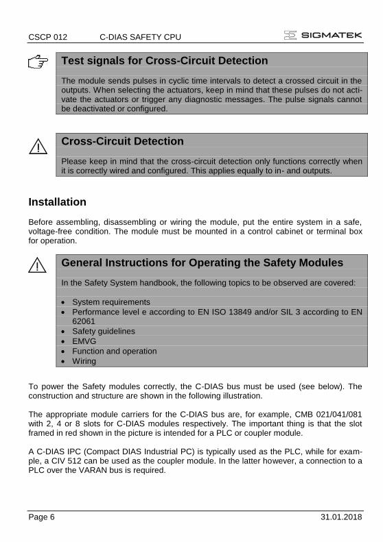
Test signals for Cross-Circuit Detection The module sends pulses in cyclic time intervals to detect a crossed circuit in the outputs. When selecting the actuators, keep in mind that these pulses do not acti-vate the actuators or trigger any diagnostic messages. The pulse signals cannot be deactivated or configured.
Cross-Circuit Detection
Please keep in mind that the cross-circuit detection only functions correctly when it is correctly wired and configured. This applies equally to in- and outputs.
Installation Before assembling, disassembling or wiring the module, put the entire system in a safe, voltage-free condition. The module must be mounted in a control cabinet or terminal box for operation.
General Instructions for Operating the Safety Modules In the Safety System handbook, the following topics to be observed are covered:
• System requirements
• Performance level e according to EN ISO 13849 and/or SIL 3 according to EN 62061
• Safety guidelines
• EMVG
• Function and operation
• Wiring
To power the Safety modules correctly, the C-DIAS bus must be used (see below). The construction and structure are shown in the following illustration. The appropriate module carriers for the C-DIAS bus are, for example, CMB 021/041/081 with 2, 4 or 8 slots for C-DIAS modules respectively. The important thing is that the slot framed in red shown in the picture is intended for a PLC or coupler module. A C-DIAS IPC (Compact DIAS Industrial PC) is typically used as the PLC, while for exam-ple, a CIV 512 can be used as the coupler module. In the latter however, a connection to a PLC over the VARAN bus is required.
C-DIAS SAFETY CPU CSCP 012
1.5 Page 7
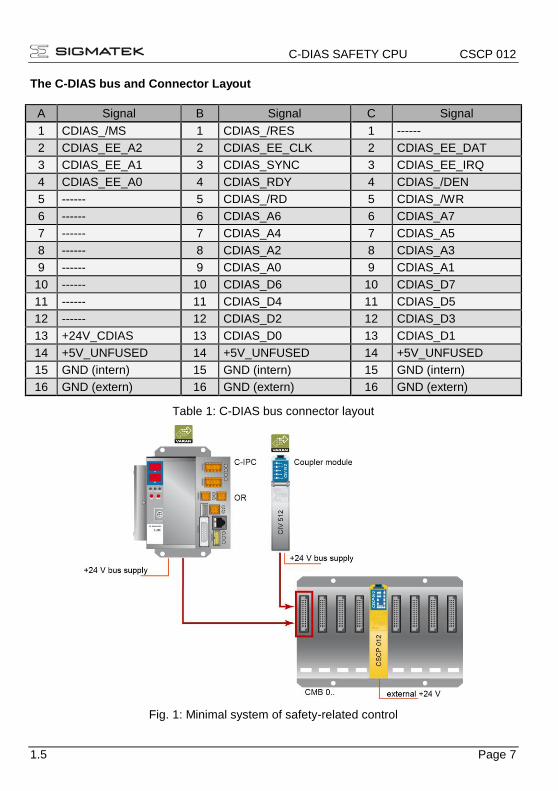
The C-DIAS bus and Connector Layout
A Signal B Signal C Signal
1 CDIAS_/MS 1 CDIAS_/RES 1 ------
2 CDIAS_EE_A2 2 CDIAS_EE_CLK 2 CDIAS_EE_DAT
3 CDIAS_EE_A1 3 CDIAS_SYNC 3 CDIAS_EE_IRQ
4 CDIAS_EE_A0 4 CDIAS_RDY 4 CDIAS_/DEN
5 ------ 5 CDIAS_/RD 5 CDIAS_/WR
6 ------ 6 CDIAS_A6 6 CDIAS_A7
7 ------ 7 CDIAS_A4 7 CDIAS_A5
8 ------ 8 CDIAS_A2 8 CDIAS_A3
9 ------ 9 CDIAS_A0 9 CDIAS_A1
10 ------ 10 CDIAS_D6 10 CDIAS_D7
11 ------ 11 CDIAS_D4 11 CDIAS_D5
12 ------ 12 CDIAS_D2 12 CDIAS_D3
13 +24V_CDIAS 13 CDIAS_D0 13 CDIAS_D1
14 +5V_UNFUSED 14 +5V_UNFUSED 14 +5V_UNFUSED
15 GND (intern) 15 GND (intern) 15 GND (intern)
16 GND (extern) 16 GND (extern) 16 GND (extern)
Table 1: C-DIAS bus connector layout
Fig. 1: Minimal system of safety-related control

CSCP 012 C-DIAS SAFETY CPU
Page 8 31.01.2018
The minimal system of a safety-related control, formed as shown above, with a C-IPC a CMB 081 and a Safety CPU type CSCP 012. The safety-related application is found in the Safety CPU and can run independently of the C-IPC. The C-IPC, however, is required to power the bus correctly and cannot be removed. In addition, it is also needed to establish the communication between the Safety CPU and the design tool (SafetyDesigner). On the C-IPC and coupler modules, connectors are provided over which the C-DIAS bus must be externally supplied with a voltage of 24 V. The external supply for the output and clock drivers should be independent of the external C-DIAS bus supply (see below). With the help from an SD card with a valid configuration, the Safety CPU can also be con-figured independently of the design tool (SafetyDesigner). More information hereto can be found in the chapter "Handling the micro SD card". With regard to the configuration using the design tool, the SafetyDesign handbook must be consulted. The Safety CPU is delivered without a password. The user must set a password in the Safety CPU.
C-DIAS SAFETY CPU CSCP 012
1.5 Page 9
C-DIAS Safety CPU CSCP 012
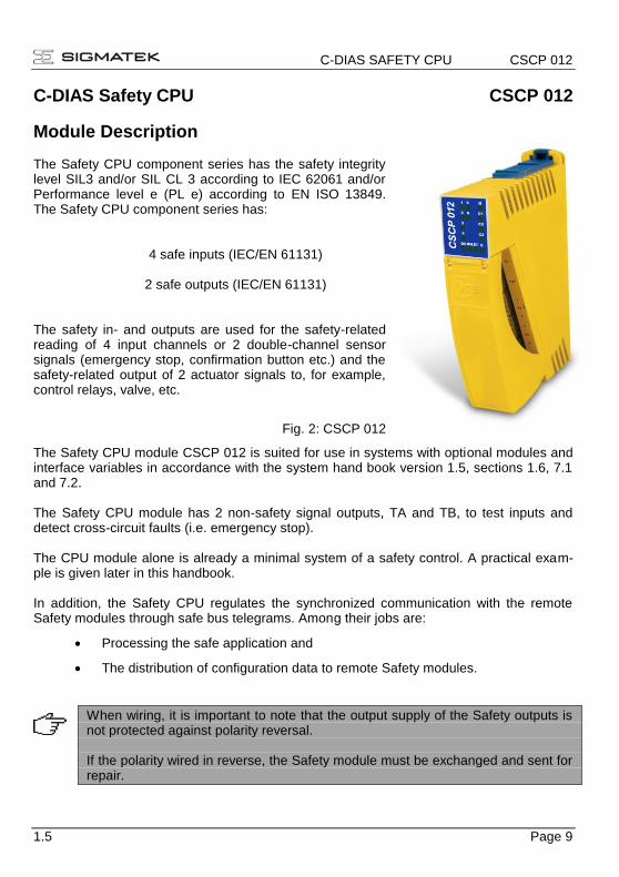
Module Description The Safety CPU component series has the safety integrity level SIL3 and/or SIL CL 3 according to IEC 62061 and/or Performance level e (PL e) according to EN ISO 13849. The Safety CPU component series has:
4 safe inputs (IEC/EN 61131)
2 safe outputs (IEC/EN 61131) The safety in- and outputs are used for the safety-related reading of 4 input channels or 2 double-channel sensor signals (emergency stop, confirmation button etc.) and the safety-related output of 2 actuator signals to, for example, control relays, valve, etc.
Fig. 2: CSCP 012
The Safety CPU module CSCP 012 is suited for use in systems with optional modules and interface variables in accordance with the system hand book version 1.5, sections 1.6, 7.1 and 7.2. The Safety CPU module has 2 non-safety signal outputs, TA and TB, to test inputs and detect cross-circuit faults (i.e. emergency stop). The CPU module alone is already a minimal system of a safety control. A practical exam-ple is given later in this handbook. In addition, the Safety CPU regulates the synchronized communication with the remote Safety modules through safe bus telegrams. Among their jobs are:
• Processing the safe application and
• The distribution of configuration data to remote Safety modules.
When wiring, it is important to note that the output supply of the Safety outputs is not protected against polarity reversal. If the polarity wired in reverse, the Safety module must be exchanged and sent for repair.
CSCP 012 C-DIAS SAFETY CPU
Page 10 31.01.2018
Designated Use The CSCP 012 Safety module is designed for use in safety-related applications and meets the required conditions for safety operation in compliance with Perfor-mance level e (PL e), according to EN ISO 13849 and/or SIL 3 according to EN 62061. It is usually used in conjunction with other Safety modules such as CSDI 162 and CSTO 082, for example. Installation, mounting, programming, initial start-up, operation, maintenance and discarding of Safety modules can only be performed by qualified personnel. Qualified personnel in this context are people, who have completed training or have been trained under supervision of qualified personnel and have been author-ized to operate and maintain safety-related equipment, systems and facilities in compliance with the strict guidelines and standards of safety technology. More in-formation on Standards etc. can be found in the Safety System Handbook. For your own safety and the safety of others, use Safety modules for their desig-nated purpose. Correct EMV installation is also included in the designated use.
Non-designated use consists of
• Any change made to the Safety modules of any kind.
• The use of damaged Safety modules.
• The use of the Safety module outside of the instructions described in this handbook.
• The use of the Safety module outside of the technical data described in this handbook.
C-DIAS SAFETY CPU CSCP 012
1.5 Page 11
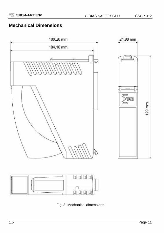
Mechanical Dimensions
Fig. 3: Mechanical dimensions
CSCP 012 C-DIAS SAFETY CPU
Page 12 31.01.2018
Technical Data
Output specifications All safety outputs are short-circuit protected and specified according to IEC/EN 61131. The outputs are compatible with input of type 1, 2 and 3.
Number of … 2
Rated output voltage +24 V DC
Output voltage range minimum +18 V maximum +30 V
Maximum output current 2 A
Maximum total current per
output group (2 outputs)
2 A
Brake voltage with switching-off
inductive loads
typically 0.85 V
Maximum switch-off energy of
the outputs (inductive load)
maximum 0.4 Joule per channel
Turn-on delay < 200 µs
Turn-off delay < 1 ms
Miscellaneous short-circuit proof
Cut-off test signal < 1.5 ms
Table 2: Output specifications
C-DIAS SAFETY CPU CSCP 012
1.5 Page 13
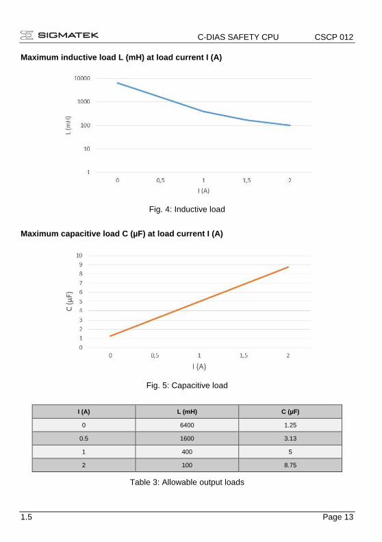
Maximum inductive load L (mH) at load current I (A)
Fig. 4: Inductive load
Maximum capacitive load C (µF) at load current I (A)
Fig. 5: Capacitive load
I (A) L (mH) C (µF)
0 6400 1.25
0.5 1600 3.13
1 400 5
2 100 8.75
Table 3: Allowable output loads
CSCP 012 C-DIAS SAFETY CPU
Page 14 31.01.2018
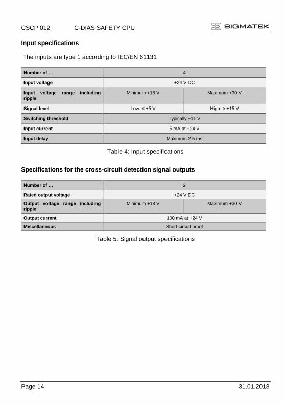
Input specifications The inputs are type 1 according to IEC/EN 61131
Number of … 4
Input voltage +24 V DC
Input voltage range including
ripple
Minimum +18 V Maximum +30 V
Signal level Low: ≤ +5 V High: ≥ +15 V
Switching threshold Typically +11 V
Input current 5 mA at +24 V
Input delay Maximum 2.5 ms
Table 4: Input specifications
Specifications for the cross-circuit detection signal outputs
Number of … 2
Rated output voltage +24 V DC
Output voltage range including
ripple
Minimum +18 V Maximum +30 V
Output current 100 mA at +24 V
Miscellaneous Short-circuit proof
Table 5: Signal output specifications
C-DIAS SAFETY CPU CSCP 012
1.5 Page 15
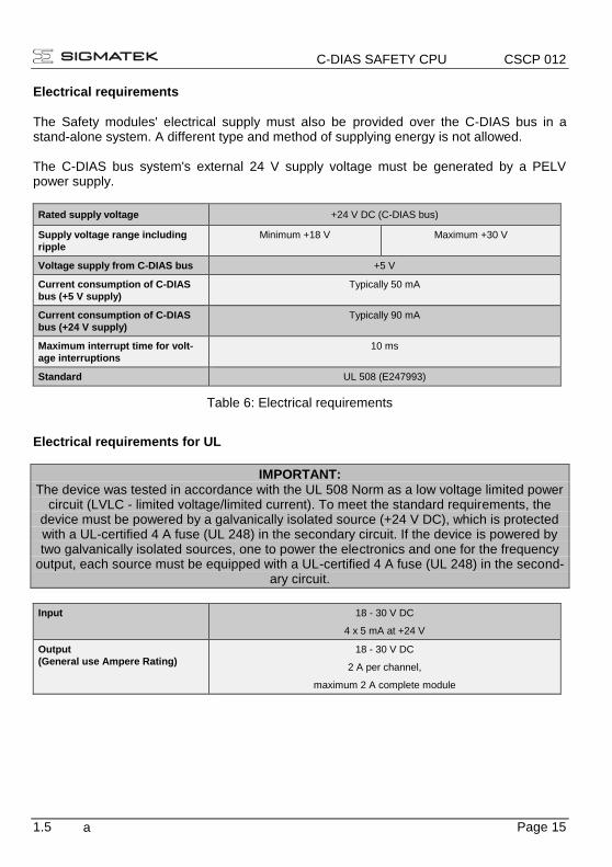
Electrical requirements The Safety modules' electrical supply must also be provided over the C-DIAS bus in a stand-alone system. A different type and method of supplying energy is not allowed. The C-DIAS bus system's external 24 V supply voltage must be generated by a PELV power supply.
Rated supply voltage +24 V DC (C-DIAS bus)
Supply voltage range including
ripple
Minimum +18 V Maximum +30 V
Voltage supply from C-DIAS bus +5 V
Current consumption of C-DIAS
bus (+5 V supply)
Typically 50 mA
Current consumption of C-DIAS
bus (+24 V supply)
Typically 90 mA
Maximum interrupt time for volt-
age interruptions
10 ms
Standard UL 508 (E247993)
Table 6: Electrical requirements
Electrical requirements for UL
IMPORTANT: The device was tested in accordance with the UL 508 Norm as a low voltage limited power
circuit (LVLC - limited voltage/limited current). To meet the standard requirements, the device must be powered by a galvanically isolated source (+24 V DC), which is protected with a UL-certified 4 A fuse (UL 248) in the secondary circuit. If the device is powered by two galvanically isolated sources, one to power the electronics and one for the frequency
output, each source must be equipped with a UL-certified 4 A fuse (UL 248) in the second-ary circuit.
Input 18 - 30 V DC
4 x 5 mA at +24 V
Output
(General use Ampere Rating)
18 - 30 V DC
2 A per channel,
maximum 2 A complete module
a

CSCP 012 C-DIAS SAFETY CPU
Page 16 31.01.2018
Safety Conformity
Conformity with EU Standards The module has been designed in accordance with the following European Union direc-tives: 2006/42/EG Machinery Directive 2014/30/EU EMC Directive 2011/65/EU RoHS Directive
Functional safety standards
- IEC 62061 SIL 3 or SIL CL 3 - EN ISO 13849 PL e / Cat. 4
Configuration: 2-channel redundant (diverse)
Safety-relevant parameters
Diagnostic coverage DC [%] 96
Probability of failure per hour PFHD [1/h] 5.8E-09
Mean time to dangerous failure MTTFD symmetrized [years] 424
Proof Test Interval [years] 20
Table 7: Safety-relevant parameters
Please note:
The parameters shown are only applicable with the simultaneous parallel
use of two inputs.

C-DIAS SAFETY CPU CSCP 012
1.5 Page 17
Environmental conditions
Storage temperature -20 to +85 °C
Operating temperature 0 to +55 °C
Humidity 0 to 95 %, uncondensed
EMV stability According to EN 61000-6-2: 2005 (industrial area) Raised requirements according to IEC 26061
Shock resistance EN 60068-2-27 15 g
Protection Type EN 60529 IP 20
Table 8: Environmental conditions
Miscellaneous
Article number 12-890-012
Hardware version 1.x
Output Power Supply So that a short circuit on the supply of the outputs resulting from an error does not cause the PLC to fail, it is recommended that separate power supplies be used for the 24 V C-DIAS bus supply (fed to the C-IPC or CIV) and the supply for the out-puts and clock signals.

CSCP 012 C-DIAS SAFETY CPU
Page 18 31.01.2018
CSCP 012 Circuit
Fig. 6: CSCP 012 circuit
For the functions and LED display, see the following chapter "LED Displays".
C-DIAS SAFETY CPU CSCP 012
1.5 Page 19
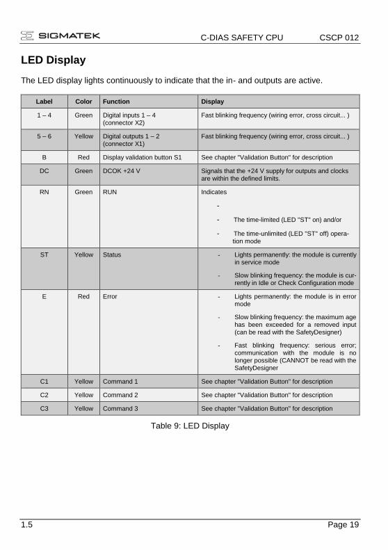
LED Display The LED display lights continuously to indicate that the in- and outputs are active.
Label Color Function Display
1 – 4 Green Digital inputs 1 – 4 (connector X2)
Fast blinking frequency (wiring error, cross circuit... )
5 – 6 Yellow Digital outputs 1 – 2 (connector X1)
Fast blinking frequency (wiring error, cross circuit... )
B Red Display validation button S1 See chapter "Validation Button" for description
DC Green DCOK +24 V Signals that the +24 V supply for outputs and clocks are within the defined limits.
RN Green RUN Indicates
-
- The time-limited (LED "ST" on) and/or
- The time-unlimited (LED "ST" off) opera-tion mode
ST Yellow Status - Lights permanently: the module is currently in service mode
- Slow blinking frequency: the module is cur-rently in Idle or Check Configuration mode
E Red Error - Lights permanently: the module is in error mode
- Slow blinking frequency: the maximum age has been exceeded for a removed input (can be read with the SafetyDesigner)
- Fast blinking frequency: serious error; communication with the module is no longer possible (CANNOT be read with the SafetyDesigner
C1 Yellow Command 1 See chapter "Validation Button" for description
C2 Yellow Command 2 See chapter "Validation Button" for description
C3 Yellow Command 3 See chapter "Validation Button" for description
Table 9: LED Display
CSCP 012 C-DIAS SAFETY CPU
Page 20 31.01.2018
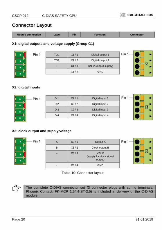
Connector Layout
Module connection Label Pin Function Connector
X1: digital outputs and voltage supply (Group G1)
X2: digital inputs
X3: clock output and supply voltage
Table 10: Connector layout
The complete C-DIAS connector set (3 connector plugs with spring terminals; Phoenix Contact: FK-MCP 1,5/ 4-ST-3.5) is included in delivery of the C-DIAS module.
TO1 X1 / 1 Digital output 1
TO2 X1 / 2 Digital output 2
+ X1 / 3 +24 V (output supply)
- X1 / 4 GND
DI1 X2 / 1 Digital input 1
DI2 X2 / 2 Digital input 2
DI3 X2 / 3 Digital input 3
DI4 X2 / 4 Digital input 4
A X3 / 1 Output A
B X3 / 2 Clock output B
+ X3 / 3 +24 V (supply for clock signal
output)
- X3 / 4 GND

C-DIAS SAFETY CPU CSCP 012
1.5 Page 21
Connector Plug Coding
Fig. 7: Connector plug coding
The Phoenix connector sets used are coded at the factory to avoid confusing the connec-tions. A red coding pin is thereby placed in the socket. Concurrently, the protruding "nose" is removed from the corresponding pin in the plug. The respective plug can therefore be inserted into the corresponding socket only. Connector plug coding: Pin 1 in plug/socket X1 Pin 2 in plug/socket X2 Pin 3 in plug/socket X3
Plug X3
Plug X2
Plug X1
Socket X3
Codierstift 3 (Pin 3)
Plug X2
Coding pin 2 (Pin 2)
Socket X1
Coding pin1 (Pin 1)
CSCP 012 C-DIAS SAFETY CPU
Page 22 31.01.2018
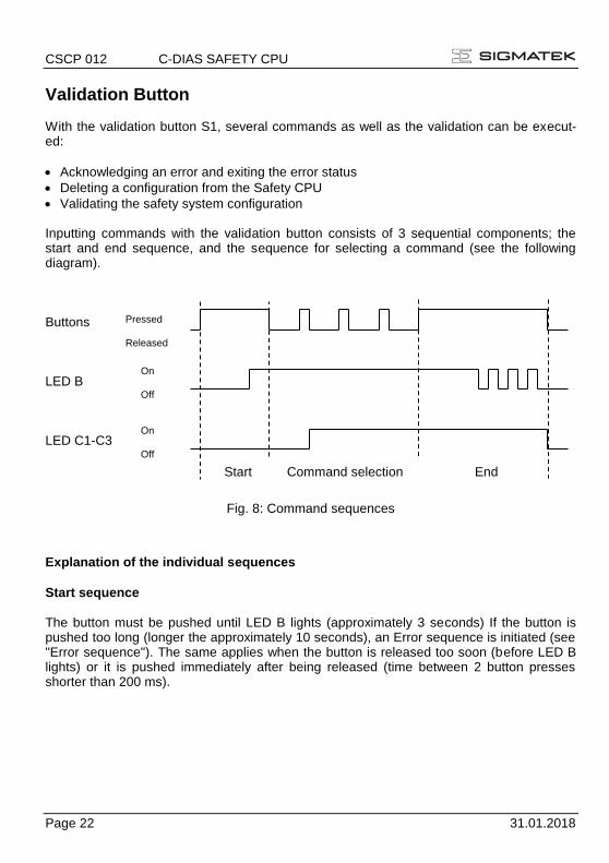
Validation Button With the validation button S1, several commands as well as the validation can be execut-ed:
• Acknowledging an error and exiting the error status
• Deleting a configuration from the Safety CPU
• Validating the safety system configuration Inputting commands with the validation button consists of 3 sequential components; the start and end sequence, and the sequence for selecting a command (see the following diagram). Buttons LED B LED C1-C3
Fig. 8: Command sequences
Explanation of the individual sequences
Start sequence The button must be pushed until LED B lights (approximately 3 seconds) If the button is pushed too long (longer the approximately 10 seconds), an Error sequence is initiated (see "Error sequence"). The same applies when the button is released too soon (before LED B lights) or it is pushed immediately after being released (time between 2 button presses shorter than 200 ms).
On
Off
On Off
Start Command selection End
Pressed Released

C-DIAS SAFETY CPU CSCP 012
1.5 Page 23
Command Selection sequence After the Start sequence, the desired command is selected. This selection is made with button presses in the following time intervals: Minimum press duration is 200 ms, maximum is approximately 3 seconds; the minimum pause between individual button presses is 200 ms, the maximum is 20 seconds. After each correct button press (incl. the minimum pause of approx. 200 ms), the selected command is shown with LEDs C1, C2 and C3. If an invalid command is selected (see "valid commands"), the Error sequence is initiated; as with not correctly observing the time intervals. LED B lights continuously during this sequence.
End sequence This sequence is used to confirm the selected command. Here, the button is pressed until LED starts to blink (approx. 3 seconds, blinks in a slow interval). The number of light pulses in LED B depends on the previously selected command (see "valid commands"). After the LED turns off, the button must be released. After the minimum pause of approxi-mately 200 ms, in which the button must not be pressed, the service mode is imitated and the command is executed. If the button pressed for longer than approximately 3 seconds, the selected command is not accepted and the Error sequence is displayed. The same applies when the button is released too soon or the minimum pause of 200 ms is not observed. After executing the command, the corresponding mode is initiated depending on the command (see "Valid Commands"). If executing the command leads to an error (i.e. because SET_VERIFIED should be exe-cuted although no valid configuration data is available in the Safety CPU), the Error se-quence is initiated.
Error sequence If an invalid button press occurs, as in the sequences described above, the Error sequence is initiated. LED B indicates this sequence with fast blinking, which lasts for at least 3 sec-onds. If the button is still pressed after 3 seconds, LED B will continue to blink until the button is released and a minimum pause of approximately 200 ms has elapsed. The Start sequence cannot be reinitiated until LED B stops blinking. After ending the Error sequence, the mode is changed as described in "Overview of Mod-ule Statuses". If turned on, LEDs C1, C2 and C3 are turned off after ending the Error se-quence.
CSCP 012 C-DIAS SAFETY CPU
Page 24 31.01.2018
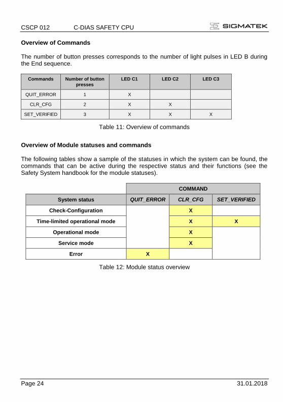
Overview of Commands The number of button presses corresponds to the number of light pulses in LED B during the End sequence.
Commands Number of button
presses
LED C1 LED C2 LED C3
QUIT_ERROR 1 X
CLR_CFG 2 X X
SET_VERIFIED 3 X X X
Table 11: Overview of commands
Overview of Module statuses and commands The following tables show a sample of the statuses in which the system can be found, the commands that can be active during the respective status and their functions (see the Safety System handbook for the module statuses).
COMMAND
System status QUIT_ERROR CLR_CFG SET_VERIFIED
Check-Configuration X
Time-limited operational mode X X
Operational mode X
Service mode X
Error X
Table 12: Module status overview
C-DIAS SAFETY CPU CSCP 012
1.5 Page 25
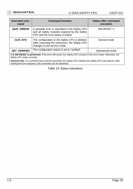
Executed com-
mand
Command function Status after command
execution
QUIT_ERROR A possible error is cancelled in the Safety CPU and all Safety modules required by the Safety CPU and the error status is ended.
SW-RESET *)
CLR_CFG The configuration in the Safety CPU is deleted. After executing the instruction, the Safety CPU changes to the service mode.
Service mode
SET_VERIFIED The configuration status is set to "verified". Operational mode
*) A SW-RESET is performed. If the error still exists, the Safety CPU remains in the error mode. Otherwise, the
Safety CPU starts correctly.
General note: If a command was entered incorrectly, the Safety CPU initiates the Safety CPU (see above). After
ending the Error sequence, the command can be reentered.
Table 13: Status transitions

CSCP 012 C-DIAS SAFETY CPU
Page 26 31.01.2018
Handling the micro SD Card An SD card can only be written on with the Safety Designer. A detailed description can be found in the LASAL SafetyDesigner configuration tools documentation. A Safety project, which was programmed with the SafetyDesigner, can be stored on an SD card. The stored Safety project can then be loaded into an additional C-DIAS Safety CPU CSCP 012, providing that the module's Flash memory is empty (cleared). If the configuration on the SD card is different from that on the Safety CPU Flash, the sys-tem switches to the error status (error message 87). The SD card cannot be inserted into the Safety CPU during normal operation (Operational or temporary operational mode). If the SD card is inserted during normal operation, the Safety CPU switches to the error status (error message 88). However, an SD card can be removed during normal operation.
Configuring a Safety CPU with the SD card The configuration is loaded from an SD card a follows:
• Delete the configuration of the Safety CPU to be programmed
To load the configuration from the SD card, the configuration in the Safety CPU must first be deleted. This can be done with either the SafetyDesigner or with help from the CLR_CFG command using validation button on the Safety CPU. Once the configuration in the Safety CPU is deleted, the Safety CPU can no longer return to the operational or temporary operational mode. The Safety CPU remains in the service mode
• Insert the SD card and deactivate the system
In the next step, an SD card with the valid configuration must be inserted in the Safety CPU and the system shut down.
• Restart the system with the SD card
When the system is restarted, the configuration is loaded from the SD card into the Flash of the Safety CPU. This is only possible it a valid configuration is stored on the SD card. If the SD card has an incorrect format (error message 86) or the Safety CPU's Flash has not been cleared (error message 87), the Safety CPU goes into the error status. If the configuration does not match the available real modules, the distribution process of the configuration triggers an error (error message 9) and the Safety CPU also goes into safe mode.
C-DIAS SAFETY CPU CSCP 012
1.5 Page 27
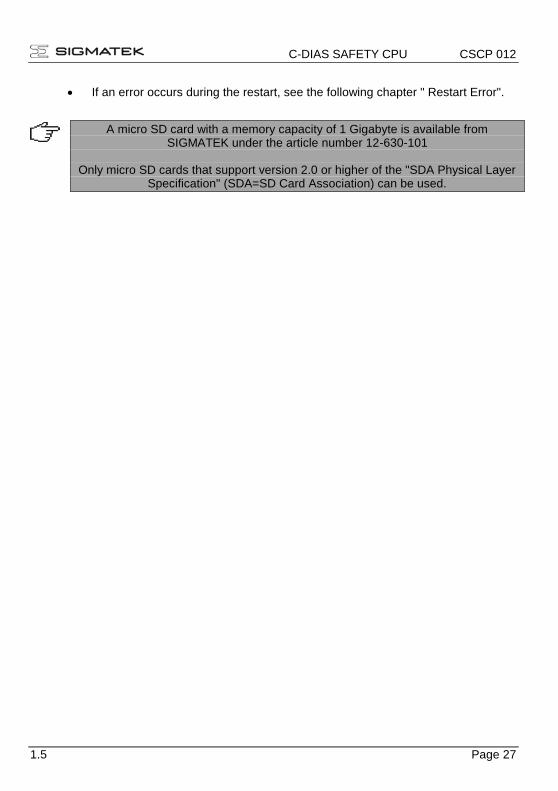
• If an error occurs during the restart, see the following chapter " Restart Error".
A micro SD card with a memory capacity of 1 Gigabyte is available from SIGMATEK under the article number 12-630-101
Only micro SD cards that support version 2.0 or higher of the "SDA Physical Layer
Specification" (SDA=SD Card Association) can be used.
CSCP 012 C-DIAS SAFETY CPU
Page 28 31.01.2018
Error Response In the event of an error, please consult the chapter "LED Displays", as important infor-mation on the runtime status of the system can be derived from the status and error dis-play. Since errors in general are of a complex nature, do not perform a diagnosis based on the LEDs alone (consult the corresponding chapter in the Safety System Handbook as well). For an exact error analysis, the SafetyDesigner must be used.
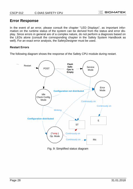
Restart Errors The following diagram shows the response of the Safety CPU module during restart.
Fig. 9: Simplified status diagram
Idle
Check Config.
Mode
(Temp.)
Op. Mode
Error
ModeKonfiguration nicht
verteilt
RNdauerhaft ON
Konfiguration verteilt
Wiederanlauf
E
ST
blinken
dauerhaft ON
dauerhaft ON
POSTService
Mode
Flash
Safe-CPU
ist leer
dauerhaft ON
Restart Flash
Safe-
Cpu is
Empty
Continously on
Continously on
Continously on
Continously on
Configuration distributed
Configuration not distributed
blinking

C-DIAS SAFETY CPU CSCP 012
1.5 Page 29
a) During restart, the Safety CPU first runs the POST (Power On Self Test). In the POST, whether the Safety CPU is configured or not is determined. If the Flash memory in the Safety CPU is empty, it changes to the service mode and switches the status LED (ST) to continuously on.
b) If the Flash memory of the Safety CPU contains a configuration, it goes into the idle / Check Configuration Mode. Thereby, an attempt is made to distribute the configuration; the ST-LED blinks during this process.
c) If the configuration is successfully distributed, the Safety CPU either goes into the Operational mode or the Temporary Operational mode depending on whether or not the configuration has already been validated. If the System was already vali-dated, the ST-LED turns off and the RN-LED lights. If the system has not been validated, both LEDs light simultaneously.
d) If for whatever reason the distribution of the configuration is still not successful, the Safety CPU switches to the Error mode and the E-LED lights
e) When the Safety CPU remains in the idle / Check Configuration Mode for a long period of time (ST-LED blinking) without switching to the Error mode, it is an indi-cation that the bus communication is malfunctioning. In this case, the PLC will re-main in the error status and must be restarted.
f) A change to the error status can also occur from the POST and (Temp.) OP mode if other (internal) errors are detected or errors in remote modules occur. The anal-ysis of these errors however, requires the use of the SafetyDesigner.
Configuration distribution error If the Safety CPU fails to distribute the configuration, the cause can be traced to one or more of the following errors.
• The configuration and the physical topology do not match
• One or more modules are missing
• More than one module was exchanged
• Communication error with a remote module
• The module to be configured is in error status

CSCP 012 C-DIAS SAFETY CPU
Page 30 31.01.2018
Troubleshooting
• Check all modules in the system for completeness and type conformity
• Check that all modules are error-free
• Check all connector cables
• Cancel the error with the QUIT_ERROR command If the Safety CPU remains in the error status after the QUIT_ERROR command has been executed, it must be retested using the SafetyDesigner.
Troubleshooting with the SafetyDesigner Connect the SafetyDesigner Debug the system using the SafetyDesigner.
Correcting a wiring error
When a wiring error is determined, a controlled deactivation of the system is re-quired, which must then be turned off.
The system can only be rewired when no power is applied.

C-DIAS SAFETY CPU CSCP 012
1.5 Page 31
Input Circuit
Fig. 10: Input circuit structure
Output Circuit
Fig. 11: Output circuit structure
Digital Input
IN 1 to IN 4 Internal logic
OUT 1
OUT 2
Internal logik
Digital output

CSCP 012 C-DIAS SAFETY CPU
Page 32 31.01.2018
Practical Example of a Circuit The following diagram shows the schematic for a processing machine. To implement the application, the following basic requirements must be met.
Requirements
R1 The installation can only be started manually with the start button S1. For cross-circuit detection, the start button S1 should have a 2-channel connection.
R2 The signal lamp P1 should turn on immediately after pressing the start button S1. To activate the signal lamp P1, a safe output can be used.
R3 For the power train control of the processing machine, a safety output should be used on the relay K1. The K1 relay should be set 500 ms after pressing the start button S1.
R4 When the Emergency Stop switch S2 is triggered, the power train control of the machine must be turned off within 50 msec.
Fig. 12: Simplified representation of the processing machine
C-DIAS SAFETY CPU CSCP 012
1.5 Page 33
Implementation
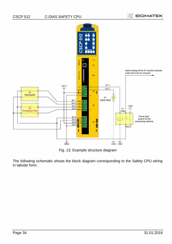
• For switch S1, the start button and S2, the Emergency Stop switch, 2 safe in-puts are required for each.
• Two safe outputs are needed for control of the relay K1 and the signal lamp P1.
• The normally open contacts of the start button S1 are connected to the signal outputs A and B over 2 channels (cross-circuit detection) and wired to 2 safe inputs.
• The normally closed contacts of the Emergency Stop switch S2, are connected to the signal outputs A and B over 2 channels (cross-circuit detection) and wired to 2 safe inputs.
• The monitor contact of the K1 relay switch is otherwise read back.
As the requirements show, the CSCP 012 Safety CPU is best suited for solving the task. The following block diagram shows the implementation of the circuit with help from a single CSCP 012 Safety CPU and the stated external components. Here, it is assumed that the Safety module is mounted on a correctly installed C-DIAS module carrier.
CSCP 012 C-DIAS SAFETY CPU
Page 34 31.01.2018
Fig. 13: Example structure diagram
The following schematic shows the block diagram corresponding to the Safety CPU wiring in tabular form.

C-DIAS SAFETY CPU CSCP 012
1.5 Page 35
Connection Diagram
Cen
tral
co
ntr
ol
str
uc
ture
wir
ing
CSCP 012
Con-
nectors Pin Connection
X1
1 Control relay K1
2 Control signal light P1
3 +24 V
4 GND
X2
1 Normally open start button S1 (B)
2 Normally open start button S1 (B)
3 Normally closed Emergency Stop S2 (A)
4 Normally closed Emergency Stop S2 (b)
X3
1 Output A
2 Clock output B
3 +24 V
4 GND
Table 14: Connection diagram example

CSCP 012 C-DIAS SAFETY CPU
Page 36 31.01.2018