c-52 wi1954.03 inst - spya express · 1 c-52 advanced adaptive ® pir/microwave technology sensor...
TRANSCRIPT

1
C-52 ADVANCED ADAPTIVE® PIR/MICROWAVE
TECHNOLOGY SENSOR WEATHER SHIELD HOUSING & SWIVEL BRACKET
MOUNTING KIT INSTALLATION INSTRUCTIONS
WI1954 2/11
GENERAL DESCRIPTION
SPECIFICATIONS General Coverage with standard wide-angle lens, measured in-
doors at 20°C (68° F), typical: 50’x40’ Note: As with all thermal detectors, the range is dependent on the difference between the target and the background. In addition, range changes are more of a possibility because of the large varying ambient temperature when the sensors are used outdoors.
Operating Temperature: -10° to +50° C (14° to 122° F) Mounting: Wall only, 6’ to 10’ max. Output Relay: Form A, Normally-Closed Relay Time: Approximately 4 seconds Contact Ratings: 100mA, 24Vdc with internal 10Ω current-limiting
resistor Trouble: Open collector current sinking with 39Ω current-limiting
resistor, 20mA max. Status Input*: Panel disarmed, >5V; armed, <1.5V. Self-Test Interval: 11-16 hours. Power-Supply Requirements: Note: This unit is intended for operation from a power source
that provides battery backup in the event of a power failure. DC: 8-16Vdc Current Drain at 12Vdc: Idle, 33mA; Alarm, 35mA Microwave Frequency: X Band; 10.525GHz Physical Dimensions: 4.5” x 2.5" x 1.7” (HxWxD) (11.4cm x
6.4cm x 4.3cm) Shipping Weight: 7oz. (198gm) CE Required Statement To meet Flammability Requirements, this unit is to be powered by an agency-approved power supply meeting the requirements of EN60950: 2000 clause 2.5 Limited Power Sources. FEATURES Note: Not all models are equipped with all features. • Microprocessor signal processing • Power-up system diagnostic tests virtually all electronics • Microwave and PIR self test • Watchdog microprocessor supervision • Microwave circuit supervision • 4-Pulse Mode for hostile environments • Quick-Response Mode while disarmed • Trouble Output • Automatic PIR operation on microwave failure • Dual-element PIR sensor • High-efficiency, dirt-resistant grooves-in lens • Extensive RFI and EMI filtering ensure optimum immunity to
false alarms • Large lens area assures high PIR sensitivity • Horizontal as well as vertical aiming capabilities • Selectable Microwave/PIR LED indication visible from virtually
any angle, extinguishable after testing
• Small size; modern, unobtrusive design • Silent operation • Swivel Bracket wall or electrical gang box mountable
ORDERING INFORMATION C-52 Long-Range Dual Technology Detector SVLBKT Swivel Bracket Kit (Wall/ Gang Box Mounting) SVL2 Swivel Bracket Kit (Wall Mounting Only) LENS122 Outdoor Lens (factory installed) BASIC OPERATION
This unit is a combination passive-infrared sensor and micro-wave sensor, both contained in a single package. The unit will go into alarm when both sensors detect intrusion at the same time.
The PIR section operates by detecting a rapid change in tem-perature when an intruder crosses a protected area. When a beam experiences a change in heat (projected back through the lens), a pulse is generated by the sensor element. The micro-wave transmitter sends out short bursts of RF energy, and the receiver detects changes in the returned signal caused by motion within its coverage area.
The microwave section is unaffected by visible light, air drafts, or temperature changes (as from air conditioners, for example), but is sensitive to motion. In contrast, infrared is virtually unaf-fected by vibration.
Thus the two complementary technologies provide an inherent immunity to false alarms. Dual technology is ideal for use in hos-tile environments. Since both must trip simultaneously to cause an alarm, installation is easier and requires less discipline.
*For UL installations, Status Input is to be connected only to a UL-listed control panel with a UL-tested Status line.
R
333 Bayview Avenue Amityville, New York 11701
For Sales and Repairs, (800) 645-9445 For Technical Service, (800) 645-9440 Publicly traded on NASDAQ Symbol: NSSC
© NAPCO 2011
TABLE OF CONTENTS GENERAL DESCRIPTION ...........................................................1
SPECIFICATIONS .....................................................................1 FEATURES ................................................................................1 ORDERING INFORMATION .....................................................1 BASIC OPERATION ..................................................................1 DETECTION PATTERNS ..........................................................2 STANDARD LENS .....................................................................2
INSTALLATION ............................................................................2 CHOOSING A SUITABLE LOCATION .....................................2 WIRING ......................................................................................2 TESTING THE COVERAGE AREA ..........................................3 COMPLETING THE INSTALLATION ........................................3 ADVANCED FEATURES ..........................................................3
MOUNTING ...................................................................................4 SVLBKT SWIVEL BRACKET INSTALLATION .........................4 SCREW TEMPLATE .................................................................6 SVL2 SWIVEL BRACKET INSTALLATION ..............................7
NAPCO LIMITED WARRANTY ....................................................8

2
DETECTION PATTERNS Figure 1 illustrates maximum PIR and microwave detection pat-terns superimposed on each other. PIR detection patterns are adjustable, within limits, both vertically and horizontally. Insensitive Areas The insensitive area is that area directly beneath the unit within which an intruder is undetectable. It is shown as a shaded area in the side-view detection pattern that follows, and assumes that an intruder will be at least 5’ tall and that the protected area is not accessible by crawling or crouching. The size of the insensitive area will increase as the mounting height increases (see Fig. 1, side view). STANDARD LENS This model uses an improved standard wide-angle lens that yields the 18-zone, 40-beam pattern illustrated in Fig. 1. The cov-erage pattern is adjustable, within limits, both vertically and hori-zontally. Stacked optical centers provide tall, dense beam pairs, making beam aiming easier and less critical. Examples shown herein are typical and will not apply to all cases. Always test the coverage pattern after the unit is installed (see TESTING THE COVERAGE AREA).
The supplied lens will perform best in typical applications, thus it is factory installed. Following are its specifications.
Number of Zones: 18 (3 layers: 9/5/4 zones) Number of Beams: 40 (3 layers: 18/10/12) Maximum Coverage: 50’ long x 40’ wide Field of View: 85° Recommended Mounting Height: 6' to 8’ Minimum Mounting Height: 6’ Maximum Mounting Height: 10’
INSTALLATION CHOOSING A SUITABLE LOCATION Select a rigid surface that is relatively free of vibration. Position
the sensor with respect to access pathways so that an intruder will pass across its field of view, not directly toward or away from it. Avoid areas with moving objects (such as swaying bushes and trees) or with devices that may pose a chronic problem to either sensor. For the dual-technology feature to be truly effective in rendering the unit free from false alarms, neither sensor should detect intrusion under normal conditions. Note: The unit is shipped from the factory with Jumper J1 in the Alarm position.
WIRING Remove the wire entry hole (see MOUNTING THE SENSOR)
to gain access to the terminal strip. (Be sure to caulk around the wires where they exit the case). Route wires to the terminal strip as shown in Fig. 2 and connect as follows:
Power (Terminals 1 [+] & 2 [-]). Apply 12VDC to Terminals 1 [+] and 2 [-]. The power source may be regulated or unregulated. Power should be supplied from a control panel or other power source equipped with a rechargeable battery backup to maintain operation in the event of a power failure. Refer to SPECIFICA-TIONS for power-supply requirements. Alarm Relay Contacts (Terminals 3 & 4). These contacts are
rated at 100mA, 24Vdc and are normally closed. When the sen-sor is operating, either detection of an intruder or loss of power will cause the relay contacts to open. Status and Trouble (Where equipped) Wiring to Terminals 5 (Status) and 6 (Trouble) are only required if using the special features of this unit. Refer to ADVANCED FEATURES.
Status Input (Terminal 5). Connect to the Status terminal (Arm Lug) of the control panel. A low at Terminal 5 tells the sensor that the panel is armed.
Trouble (Terminal 6). This is an open-collector output that pro-duces an active low to signal a trouble condition.
Self Test The self-test diagnostic simulates motion and tests the PIR sen-sor, amplifier and related PIR circuitry, the microwave transmit-ter, receiver, and associated microwave circuitry. This test is initiated each time the unit is powered up and randomly at 11- to 16-hour intervals after the last alarm to ensure that the unit is always in operating order. At power-up, the LED will turn on and both the alarm and trouble outputs will be held “safe’. If the unit is operating properly, the LED will extinguish after about 1 min-ute. However, if it fails the self test, the LED will flash rapidly, indicating a need for service. After the LED goes out, indicating a successful self-test, proceed as follows:
Setting the Height Scale For fixed wall mounting (without a Swivel Bracket Kit), the circuit
Fig. 1. C-52 Standard Wide-Angle Lens Pattern.
CORNER MOUNT HOLE JUMPER BLOCK
INDEX NOTCH
HEIGHT SCALE
HEIGHT LOCK SCREW (DEPENDING ON MODEL)
MICROWAVE CAVITY
MICROWAVE RANGE CONTROL CORNER MOUNT HOLE LED
PIR SENSOR
TAMPER TERMINALS (TAMPER OPTIONAL)
WALL MOUNT HOLE CORNER MOUNT HOLE
PINOUT,FORM-A RELAY
*WHERE EQUIPPED
ALAR
M
TROU
BLE*
STAT
US* NC
1 2 3 5 6 4
POW
ER + −
TO 24HR ZONE
NC*
TAMPER (OPTIONAL) 7 8
*WHEN SET
NOTE: (1) NOT ALL TERMINALS AVAILABLE IN ALL VERSIONS. (2) NC WHEN SET.
Fig. 2. Circuit board layout.
3
board Height Scale can be adjusted to compensate for the mounting height of the sensor, obtaining maximum coverage. However, because the C-52 itself is adjustable via a Swivel Bracket Kit, there is no need to use the Height Scale to compen-sate for its mounting height. Therefore, to optimize the optical position of the sensor with respect to the lens, be sure the circuit board is in its lowest position. Remove the front cover (the Height scale is printed along the edge of the circuit board in the upper-left corner). Loosen the Lock Screw (shown in Fig. 2), and slide the circuit board down. Then tighten the Lock Screw (do not over-tighten!).
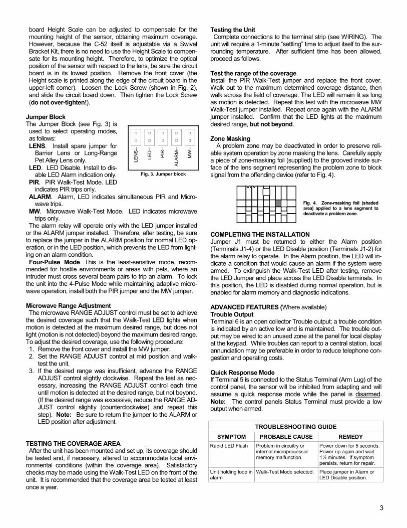
Jumper Block The Jumper Block (see Fig. 3) is used to select operating modes, as follows: LENS. Install spare jumper for
Barrier Lens or Long-Range Pet Alley Lens only.
LED. LED Disable. Install to dis-able LED Alarm indication only.
PIR. PIR Walk-Test Mode. LED indicates PIR trips only.
ALARM. Alarm, LED indicates simultaneous PIR and Micro-wave trips.
MW. Microwave Walk-Test Mode. LED indicates microwave trips only.
The alarm relay will operate only with the LED jumper installed or the ALARM jumper installed. Therefore, after testing, be sure to replace the jumper in the ALARM position for normal LED op-eration, or in the LED position, which prevents the LED from light-ing on an alarm condition. Four-Pulse Mode. This is the least-sensitive mode, recom-
mended for hostile environments or areas with pets, where an intruder must cross several beam pairs to trip an alarm. To lock the unit into the 4-Pulse Mode while maintaining adaptive micro-wave operation, install both the PIR jumper and the MW jumper. Microwave Range Adjustment The microwave RANGE ADJUST control must be set to achieve
the desired coverage such that the Walk-Test LED lights when motion is detected at the maximum desired range, but does not light (motion is not detected) beyond the maximum desired range. To adjust the desired coverage, use the following procedure: 1. Remove the front cover and install the MW jumper. 2. Set the RANGE ADJUST control at mid position and walk-
test the unit. 3. If the desired range was insufficient, advance the RANGE
ADJUST control slightly clockwise. Repeat the test as nec-essary, increasing the RANGE ADJUST control each time until motion is detected at the desired range, but not beyond. (If the desired range was excessive, reduce the RANGE AD-JUST control slightly (counterclockwise) and repeat this step). Note: Be sure to return the jumper to the ALARM or LED position after adjustment.
TESTING THE COVERAGE AREA After the unit has been mounted and set up, its coverage should
be tested and, if necessary, altered to accommodate local envi-ronmental conditions (within the coverage area). Satisfactory checks may be made using the Walk-Test LED on the front of the unit. It is recommended that the coverage area be tested at least once a year.
Testing the Unit Complete connections to the terminal strip (see WIRING). The
unit will require a 1-minute “settling” time to adjust itself to the sur-rounding temperature. After sufficient time has been allowed, proceed as follows. Test the range of the coverage. Install the PIR Walk-Test jumper and replace the front cover. Walk out to the maximum determined coverage distance, then walk across the field of coverage. The LED will remain lit as long as motion is detected. Repeat this test with the microwave MW Walk-Test jumper installed. Repeat once again with the ALARM jumper installed. Confirm that the LED lights at the maximum desired range, but not beyond. Zone Masking
A problem zone may be deactivated in order to preserve reli-able system operation by zone masking the lens. Carefully apply a piece of zone-masking foil (supplied) to the grooved inside sur-face of the lens segment representing the problem zone to block signal from the offending device (refer to Fig. 4).
Fig. 4. Zone-masking foil (shaded area) applied to a lens segment to deactivate a problem zone.
COMPLETING THE INSTALLATION Jumper J1 must be returned to either the Alarm position (Terminals J1-4) or the LED Disable position (Terminals J1-2) for the alarm relay to operate. In the Alarm position, the LED will in-dicate a condition that would cause an alarm if the system were armed. To extinguish the Walk-Test LED after testing, remove the LED Jumper and place across the LED Disable terminals. In this position, the LED is disabled during normal operation, but is enabled for alarm memory and diagnostic indications. ADVANCED FEATURES (Where available) Trouble Output Terminal 6 is an open collector Trouble output; a trouble condition is indicated by an active low and is maintained. The trouble out-put may be wired to an unused zone at the panel for local display at the keypad. While troubles can report to a central station, local annunciation may be preferable in order to reduce telephone con-gestion and operating costs. Quick Response Mode If Terminal 5 is connected to the Status Terminal (Arm Lug) of the control panel, the sensor will be inhibited from adapting and will assume a quick response mode while the panel is disarmed. Note: The control panels Status Terminal must provide a low output when armed.
SYMPTOM PROBABLE CAUSE REMEDY Rapid LED Flash Problem in circuitry or
internal microprocessor memory malfunction.
Power down for 5 seconds. Power up again and wait 1½ minutes. If symptom persists, return for repair.
Unit holding loop in alarm
Walk-Test Mode selected. Place jumper in Alarm or LED Disable position.
TROUBLESHOOTING GUIDE
LE
NS
--
LED
--
PIR
--
ALA
RM
--
MW
--
Fig. 3. Jumper block

4
MOUNTING
The C-52 sensor can be mounted in either of two ways: (A) On to a wall or electrical gang box using a SVLBKT Swivel Bracket , or (B) On to a wall using a SVL2 Swivel Bracket. Either method makes use of the same Weather Shield Housing, which is a metal enclosure designed for protecting the Sensor from a hostile outdoor environment. The C-52 sensor is affixed inside this Weather Shield Housing, and sealed against mois-ture with an O-Ring that is installed in the base of the sensor. The images below display each type of assembled bracket, with the Weather Shield Housing affixed.
Note: Mounting hardware for either mounting method is pack-aged separately. The hardware used for method "A" is included in a clear plastic bag marked "A" and hardware for method "B" is included in a clear plastic bag marked "B". First select a mounting method for your application, and then be sure to select the proper mounting hardware as necessary. For the SVL2 assembly instructions (Section B), go to page 7. For the SVLBKT assembly instructions (Section A), proceed as follows: A: OUTDOOR WEATHER SHIELD HOUSING & SVLBKT SWIVEL BRACKET INSTALLATION For Wall or Electrical Gang Box Mounting
The SVLBKT Swivel Bracket is used to mount the space-protection unit into the weather shield. The SVLBKT bracket can mount onto a single-gang box using the screws supplied, or it may be mounted directly onto the wall using appropriate screws. For mounting the SVLBKT, gather the following items:
(1) Wall Plate (1) Ball Bracket (2) Ball Halves BAG "A" Containing:
(1) 6-32x5/8" Hex Head Thread Cutting Screw (2) #6x5/16" Self-Tapping Screws (2) 6-32x1/2" Oval Head Machine Screws (1) 1/4" Box Wrench is supplied.
A third bag contains the O-Ring. ASSEMBLY INSTRUCTIONS 1. Separate the front cover of the sensor from the rear sensor
housing. 2. Remove the PC board from the rear sensor housing. 3. Referring to the image, slip each Ball Half through the Ball
Bracket, then fit the two halves together. 4. Insert the tab on the Ball Bracket into the slot in the Wall
Plate. Then, install the 6-32x5/8" Hex Head Machine Screw through the small hole in the Ball Bracket and into the Wall Plate--but DO NOT tighten fully until aiming is complete.
5. Secure the Weather Shield Housing to the Ball Bracket as-
sembly using the two #6x5/16" Self-Tapping screws (see im-ages on next page).
(A): SVLBKT Swivel Bracket (above)
(B): SVL2 Swivel Bracket
DO NOT tighten fully until aiming
is complete
A: FINISHED ASSEMBLY (SVLBKT)
Wall Plate
Ball Bracket
Weather Shield Housing
5
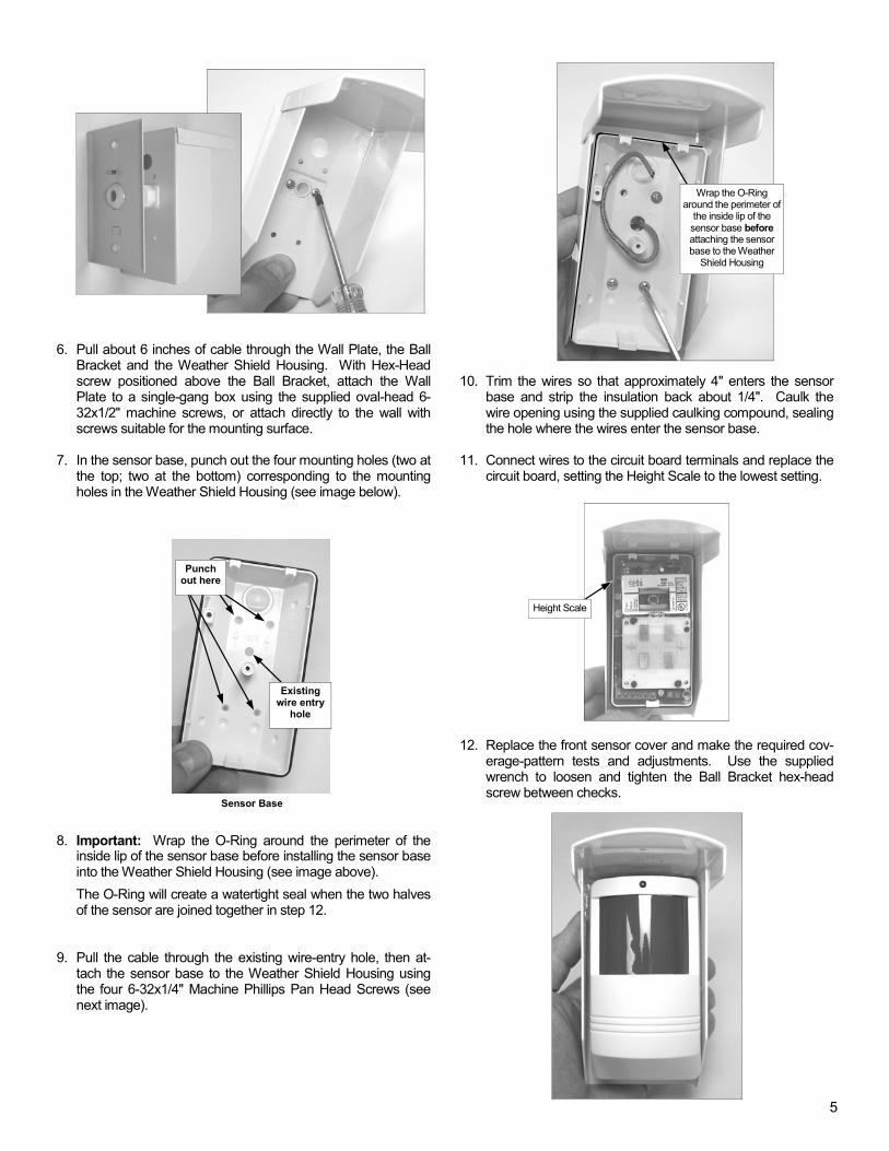
6. Pull about 6 inches of cable through the Wall Plate, the Ball
Bracket and the Weather Shield Housing. With Hex-Head screw positioned above the Ball Bracket, attach the Wall Plate to a single-gang box using the supplied oval-head 6-32x1/2" machine screws, or attach directly to the wall with screws suitable for the mounting surface.
7. In the sensor base, punch out the four mounting holes (two at
the top; two at the bottom) corresponding to the mounting holes in the Weather Shield Housing (see image below).
8. Important: Wrap the O-Ring around the perimeter of the
inside lip of the sensor base before installing the sensor base into the Weather Shield Housing (see image above).
The O-Ring will create a watertight seal when the two halves of the sensor are joined together in step 12.
9. Pull the cable through the existing wire-entry hole, then at-
tach the sensor base to the Weather Shield Housing using the four 6-32x1/4" Machine Phillips Pan Head Screws (see next image).
10. Trim the wires so that approximately 4" enters the sensor
base and strip the insulation back about 1/4". Caulk the wire opening using the supplied caulking compound, sealing the hole where the wires enter the sensor base.
11. Connect wires to the circuit board terminals and replace the
circuit board, setting the Height Scale to the lowest setting. 12. Replace the front sensor cover and make the required cov-
erage-pattern tests and adjustments. Use the supplied wrench to loosen and tighten the Ball Bracket hex-head screw between checks.
Wrap the O-Ring around the perimeter of
the inside lip of the sensor base before attaching the sensor base to the Weather
Shield Housing
Sensor Base
Punch out here
Existing wire entry
hole
Height Scale
6
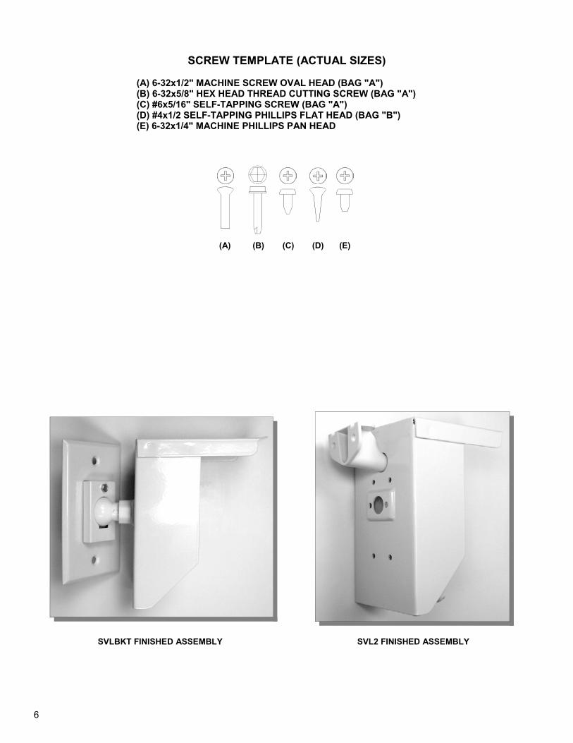
SCREW TEMPLATE (ACTUAL SIZES)
(A) 6-32x1/2" MACHINE SCREW OVAL HEAD (BAG "A") (B) 6-32x5/8" HEX HEAD THREAD CUTTING SCREW (BAG "A") (C) #6x5/16" SELF-TAPPING SCREW (BAG "A") (D) #4x1/2 SELF-TAPPING PHILLIPS FLAT HEAD (BAG "B") (E) 6-32x1/4" MACHINE PHILLIPS PAN HEAD
(A) (B) (C) (D) (E)
SVLBKT FINISHED ASSEMBLY SVL2 FINISHED ASSEMBLY

7
B: OUTDOOR WEATHER SHIELD HOUSING & SVL2 SWIVEL BRACKET INSTALLATION For Wall Mounting Only
The SVL2 Swivel Bracket is used to mount the space-protection unit into the weather shield. The SVL2 bracket can be mounted directly onto the wall using appropriate screws. For mounting the SVL2, Find the clear plastic bag marked "Bag B" which contains the following items:
(1) #4x1/2" Phillips Flat Head Self-Tapping Screw (1) Swivel Mount Washer Find a third bag containing the O-Ring and the (4) 6-32x1/4" Machine Phillips Pan Head Screws.
ASSEMBLY INSTRUCTIONS 1. Separate the front sensor cover from the rear sensor
base. 2. Remove the PC board from
the rear sensor base. In the sensor base, punch out the four mounting holes (two at the top; two at the bottom) corresponding to the mount-ing holes in the Weather Shield Housing. In addition, punch out the top hole in the sensor base as shown.
3. Attach the Swivel Mount
Bracket to the wall according to the specified mounting height. Note: Do NOT mount on ceil-ings.
4. Place the sensor base into the Weather Shield Housing. Important: Wrap the O-Ring around the perimeter of the inside lip of the sensor base before installing the sensor base into the Weather Shield Housing. The O-Ring will create a watertight seal when the two halves of the sensor are joined together in step 9. See image below.
5. Place the Swivel Mount
Washer on the inside of the sensor base top hole.
6. Insert the Flat Head Screw
into Swivel Mount Washer, through the hole in the sen-sor base, through the hole in the Weather Shield Housing and into the Swivel Mount Bracket. Adjust the unit and tighten the Flat Head Screw when the desired angle is obtained.
7. Pull the cable through
the existing wire-entry hole, then attach the rear case of the unit to the Weather Shield Housing using the four #6-32x1/4" Phillips Pan Head machine screws.
8. Trim the wires so that
approximately 4" enters the case and strip the insulation back about 1/4". Caulk the wire opening using the sup-plied caulking com-pound, sealing the hole where the wires enter the sensor base.
9. Replace the PC board inside the sensor base. Connect
wires to the circuit board terminals and replace the circuit board, setting the Height Scale to the lowest setting. With the O-Ring in place (installed in step 4), replace the front sensor cover and make the required coverage-pattern tests and adjustments.
FINISHED ASSEMBLY (SVL2)
SVL2 Swivel Mount Bracket
Weather Shield Housing
Flat Head Screw
Swivel Mount Washer
Rear Sensor Housing
Attach rear case using four 6-
32x1/4" Machine Screws
Sensor Base
Existing wire entry
hole
Punch out here
Wrap the O-Ring around the perimeter of
the inside lip of the sensor base before attaching the sensor base to the Weather
Shield Housing
Swivel Mount Washer

8
NAPCO SECURITY SYSTEMS, INC. (NAPCO) war-rants its products to be free from manufacturing de-fects in materials and workmanship for thirty-six months following the date of manufacture. NAPCO will, within said period, at its option, repair or replace any product failing to operate correctly without charge to the original purchaser or user. This warranty shall not apply to any equipment, or any part thereof, which has been repaired by others, im-properly installed, improperly used, abused, altered, damaged, subjected to acts of God, or on which any serial numbers have been altered, defaced or re-moved. Seller will not be responsible for any disman-tling or reinstallation charges. THERE ARE NO WARRANTIES, EXPRESS OR IM-PLIED, WHICH EXTEND BEYOND THE DESCRIP-TION ON THE FACE HEREOF. THERE IS NO EX-PRESS OR IMPLIED WARRANTY OF MERCHANT-ABILITY OR A WARRANTY OF FITNESS FOR A PARTICULAR PURPOSE. ADDITIONALLY, THIS WARRANTY IS IN LIEU OF ALL OTHER OBLIGA-TIONS OR LIABILITIES ON THE PART OF NAPCO. Any action for breach of warranty, including but not lim-ited to any implied warranty of merchantability, must be brought within the six months following the end of the warranty period. IN NO CASE SHALL NAPCO BE LI-ABLE TO ANYONE FOR ANY CONSEQUENTIAL OR INCIDENTAL DAMAGES FOR BREACH OF THIS OR ANY OTHER WARRANTY, EXPRESS OR IMPLIED, EVEN IF THE LOSS OR DAMAGE IS CAUSED BY THE SELLER’S OWN NEGLIGENCE OR FAULT. In case of defect, contact the security professional who installed and maintains your security system. In order to exercise the warranty, the product must be returned by the security professional, shipping costs prepaid and insured to NAPCO. After repair or replacement, NAPCO assumes the cost of returning products under warranty. NAPCO shall have no obligation under this warranty, or otherwise, if the product has been re-paired by others, improperly installed, improperly used, abused, altered, damaged, subjected to accident, nui-sance, flood, fire or acts of God, or on which any serial numbers have been altered, defaced or removed. NAPCO will not be responsible for any dismantling, re-assembly or reinstallation charges. This warranty contains the entire warranty. It Is the sole warranty and any prior agreements or repre-sentations, whether oral or written, are either merged herein or are expressly cancelled. NAPCO neither assumes, nor authorizes any other person purporting to act on its behalf to modify, to
change, or to assume for it, any other warranty or liability concerning its products. In no event shall NAPCO be liable for an amount in ex-cess of NAPCO's original selling price of the product, for any loss or damage, whether direct, indirect, inci-dental, consequential, or otherwise arising out of any failure of the product. Seller’s warranty, as herein-above set forth, shall not be enlarged, diminished or affected by and no obligation or liability shall arise or grow out of Seller’s rendering of technical advice or service in connection with Buyer’s order of the goods furnished hereunder. NAPCO RECOMMENDS THAT THE ENTIRE SYS-TEM BE COMPLETELY TESTED WEEKLY. Warning: Despite frequent testing, and due to, but not limited to, any or all of the following; criminal tamper-ing, electrical or communications disruption, it is possi-ble for the system to fail to perform as expected. NAPCO does not represent that the product/system may not be compromised or circumvented; or that the product or system will prevent any personal injury or property loss by burglary, robbery, fire or otherwise; nor that the product or system will in all cases provide adequate warning or protection. A properly installed and maintained alarm may only reduce risk of burglary, robbery, fire or otherwise but it is not insurance or a guarantee that these events will not occur. CONSE-QUENTLY, SELLER SHALL HAVE NO LIABILITY FOR ANY PERSONAL INJURY, PROPERTY DAM-AGE, OR OTHER LOSS BASED ON A CLAIM THE PRODUCT FAILED TO GIVE WARNING. Therefore, the installer should in turn advise the consumer to take any and all precautions for his or her safety including, but not limited to, fleeing the premises and calling po-lice or fire department, in order to mitigate the possibili-ties of harm and/or damage. NAPCO is not an insurer of either the property or safety of the user’s family or employees, and limits its liability for any loss or damage including incidental or consequential damages to NAPCO’s original selling price of the product regardless of the cause of such loss or damage. Some states do not allow limitations on how long an implied warranty lasts or do not allow the exclusion or limitation of incidental or consequential damages, or differentiate in their treatment of limitations of liability for ordinary or gross negligence, so the above limita-tions or exclusions may not apply to you. This War-ranty gives you specific legal rights and you may also have other rights which vary from state to state.
NAPCO LIMITED WARRANTY