by order of the air force pamphlet 23-221 … · by order of the secretary of the air force air...
TRANSCRIPT

BY ORDER OF THE
SECRETARY OF THE AIR FORCE
AIR FORCE PAMPHLET 23-221
11 MARCH 2013
Materiel Management
FUELS LOGISTICS PLANNING
COMPLIANCE WITH THIS PUBLICATION IS MANDATORY
ACCESSIBILITY: Publications and forms are available on the e-publishing website at
www.e-publishing.af.mil/ for downloading or ordering.
RELEASABILITY: There are no releasability restrictions on this publication.
OPR: AF/A4LE
Supersedes: AFPAM23-221,
22 December 2006
Certified by: AF/A4L
(Maj Gen John B. Cooper)
Pages: 102
This pamphlet establishes basic guidance for planning and executing fuel support operations,
particularly at other than main operating bases. It implements Air Force Policy Directive
(AFPD) 23-2, Management of Bulk Petroleum and Related Products. It identifies logistics
planning factors and guidance on fuel-related products, equipment, and support procedures. This
pamphlet applies to all Air Force activities involved in fuel support operations, including the US
Air Force Reserve and the Air National Guard. Refer recommended changes and questions about
this publication to the Office of Primary Responsibility (OPR) using the AF Form 847,
Recommendation for Change of Publication; route AF Form 847s from the field through the
appropriate functional chain of command. This publication may be supplemented at any level,
but all direct Supplements must be routed to the OPR of this publication prior to certification and
approval. The use of any specific manufacturer name, commercial product, commodity, or
service in this publication does not imply endorsement by the Air Force. Ensure that all records
created as a result of processes prescribed in this publication are maintained in accordance with
(IAW) Air Force Manual (AFMAN) 33-363, Management of Records, and disposed of IAW Air
Force Records Information Management System (AFRIMS) Records Disposition Schedule
(RDS) located at https://www.my.af.mil/afrims/afrims/afrims/rims.cfm
SUMMARY OF CHANGES
This is the fourth revision of AFPAM 23-221. Major changes to this document include handling
guidance for Aviation Gasoline (AVGAS), the aircraft planning factor table, the link to the Unit
Type Code (UTC) Mission Capability (MISCAP) statements, cryogenic requirements
determination, updated decision logic table, and Fuels Support Equipment (FSE) Program

2 AFPAM23-221 11 MARCH 2013
Management Structure and Responsibilities. This publication must be reviewed in its entirety
due to these major revisions.
Chapter 1—GENERAL INFORMATION ABOUT THIS PAMPHLET AND FUELS 5
1.1. Purpose of this pamphlet. ....................................................................................... 5
1.2. Basic Fuels Logistics Planning. ............................................................................. 5
Chapter 2—FUNCTIONS AND RESPONSIBILITIES 6
2.1. Major Command (MAJCOM) Fuels. ..................................................................... 6
2.2. The Combatant Commander (CCDR). .................................................................. 6
2.3. DLA Energy. .......................................................................................................... 6
2.4. Logistics Readiness Squadron (LRS). ................................................................... 6
2.5. Air Force Petroleum Agency (AFPA). .................................................................. 6
2.6. Fuels Management Team (FMT). .......................................................................... 7
2.7. Refueling Maintenance. ......................................................................................... 7
2.8. Civil Engineers. ..................................................................................................... 8
2.9. Airfield Management. ............................................................................................ 8
Chapter 3—AIRFIELD SUPPORT 9
3.1. Airfield Surveys. .................................................................................................... 9
3.2. Host Nation Support. ............................................................................................. 9
3.3. Memorandum of Agreement (MOA). .................................................................... 9
3.4. Fuel Availability. ................................................................................................... 9
3.5. Quality Control. ..................................................................................................... 10
Chapter 4—FUEL SUPPORT 11
4.1. Computing Requirements. ..................................................................................... 11
4.2. Resupply Options. .................................................................................................. 12
4.3. Aircraft Systems. ................................................................................................... 13
4.4. Storage Options. ..................................................................................................... 13
4.5. Additives. ............................................................................................................... 14
4.6. Ground Fuels. ......................................................................................................... 14
4.7. Personnel and Equipment Requirements. .............................................................. 15
Chapter 5—FUELS EQUIPMENT INTEROPERABILITY 16
5.1. Dispensing Options. ............................................................................................... 16
5.2. Joint Interoperability. ............................................................................................. 16

AFPAM23-221 11 MARCH 2013 3
5.3. Nonstandard Refueling Operations. ....................................................................... 16
5.4. Couplings, Nozzles, and Adaptors. ........................................................................ 17
Chapter 6—CRYOGENICS 18
6.1. Availability. ........................................................................................................... 18
6.2. Storage. .................................................................................................................. 18
6.3. Issue. ...................................................................................................................... 18
6.4. Requirements. ........................................................................................................ 18
Chapter 7—SPECIAL FUELS 19
7.1. Thermally Stable Jet Fuel (JPTS). ......................................................................... 19
7.2. Aviation Gasoline (AVGAS). ................................................................................ 19
Chapter 8—ADMINISTRATION AND ACCOUNTING 20
8.1. Reporting. .............................................................................................................. 20
8.2. Security. ................................................................................................................. 20
8.3. Communications. ................................................................................................... 20
8.4. Transportation. ....................................................................................................... 20
8.5. Accounting. ............................................................................................................ 20
8.6. Deployed Fuel Dispensing Vehicle/Equipment Deficiency Reporting. ................ 20
Chapter 9—PERSONNEL 22
9.1. Responsibilities. ..................................................................................................... 22
9.2. Management. .......................................................................................................... 22
9.3. Morale and Welfare. .............................................................................................. 22
9.4. Host Nation Relations. ........................................................................................... 22
Chapter 10—FUELS FORCE MODULES (IAW AFI 10-401) 23
10.1. The AETF force modules. ...................................................................................... 23
10.2. AEF Sourcing Plans and Tasks Timeline. ............................................................. 23
10.3. AEF Schedule Preparation Timeline. .................................................................... 23
Attachment 1—GLOSSARY OF REFERENCES AND SUPPORTING INFORMATION 25
Attachment 2—FUELS LOGISTICS PLANNING GUIDANCE CONSIDERATIONS 36
Attachment 3—AIRFIELD FUELS SITE SURVEY 41
Attachment 4—PRODUCT SPECIFICATIONS AND TYPICAL PROPERTIES 46
Attachment 5—SUPPORT PACKAGES 51

4 AFPAM23-221 11 MARCH 2013
Attachment 6—CONVERSION FACTORS 52
Attachment 7—AIRCRAFT PLANNING FACTORS 61
Attachment 8—EQUIPMENT AND MANPOWER DECISION LOGIC 67
Attachment 9—INTERSERVICE FUELS EQUIPMENT AND SYSTEMS 69
Attachment 10—CONTINGENCY LOCATION SET-UP CHECKLIST 96
Attachment 11—FUELS PERSONNEL AND EQUIPMENT UNIT TYPE CODES (UTC) 98
Attachment 12—FSE PROGRAM MANAGEMENT STRUCTURE/RESPONSIBILITIES 99

AFPAM23-221 11 MARCH 2013 5
Chapter 1
GENERAL INFORMATION ABOUT THIS PAMPHLET AND FUELS
1.1. Purpose of this pamphlet. This pamphlet provides logistics planning guidance for fuels
planners to aid in establishing petroleum support capabilities at locations other than US Air
Force main operating bases.
1.2. Basic Fuels Logistics Planning.
1.2.1. The Air Force must maintain the ability to deploy rapidly and effectively to a variety
of base environments ranging from bare bases to fully equipped, international airports. Once
in place, US forces must be able to operate with the full spectrum of fuels support. A bare-
base must have a runway, taxiway, and parking area adequate for the deployed force and an
adequate source of water that can be made potable. Developed foreign military or civilian
airfields may be comparable to true bare-base operations because of inadequate real estate
and access to a runway. Deploying forces to these locations must prepare to support
themselves as in a real bare-base environment.
1.2.2. Experience has shown that fuels personnel at all levels may be required to provide
fuels logistics planning to support exercises or real-world contingencies. While these
persons may have little experience in the planning process, they are nevertheless expected to
perform in field conditions, with limited technical supervision and communications. This
publication provides basic guidance for managing the use of logistic resources and for
ensuring that critical phases of the fuels planning process are not overlooked. It does not
preclude the need to use other directives and technical orders. Information contained in this
pamphlet should help you analyze mission requirements and allocate resources to develop an
effective and efficient support package.
1.2.3. The Department of Defense (DoD) wartime adaptive planning concept uses the Joint
Operation Planning Execution System (JOPES) to develop operational plans. In response to
short-notice contingencies, a shortened form of contingency planning known as the Crisis
Action Planning (CAP) is used. Air Force JOPES guidance can be found in AFI 10-401, Air
Force Operations Planning and Execution. Fuels planners are responsible for identifying
petroleum and cryogenic requirements. They are also responsible for determining, arranging
and executing the required support to meet mission demands. To do this requires at least a
limited knowledge of the planning process. This publication helps provide that background.
1.2.4. For the purpose of this pamphlet, a planning cycle is considered as (1) a preplanning
phase where requirements are determined and an initial support proposal drafted; (2) a site
survey phase to verify the feasibility of support proposal; (3) actual plan execution; and (4)
after-action planning where the operation is analyzed for lessons learned. This pamphlet is
designed to be especially helpful in those situations where phases 1 and 2 are compressed or
eliminated. Attachment 2 gives fuels logistics planning guidance for use during planning and
execution.
1.2.5. All Fuels planners must refer to AFI 10-401 and AFI 10-403, Deployment Planning
and Execution, for further guidance.

6 AFPAM23-221 11 MARCH 2013
Chapter 2
FUNCTIONS AND RESPONSIBILITIES
2.1. Major Command (MAJCOM) Fuels.
2.1.1. The MAJCOM or their respective Numbered Air Force (NAF) personnel are
responsible for the development of theater/base specific fuel support plans, providing support
for Site Surveys and sourcing equipment and personnel required to support Air Forces
operating in their Area of Responsibility. It is highly recommended that MAJCOM and NAF
fuels personnel attend the Contingency War Planners Course (CWPC) at Maxwell AFB.
Once fuels personnel have completed CWPC, they must follow the guidance in the Air Force
Enlisted Classification Directory (AFECD) for award of the “R” prefix, Contingency War
Planner.
2.2. The Combatant Commander (CCDR).
2.2.1. The CCDR has the predominant fuels responsibility within a theater, the Joint
Petroleum Office (JPO) discharges this responsibility. The JPO is responsible for the overall
planning of petroleum logistic support for joint operations within their Area of Responsibility
(AOR). This responsibility may be further delegated to a Sub-Area Petroleum Office
(SAPO) responsible for a subset of the AOR. The JPOs work closely with their respective
MAJCOM/Numbered Air Force service components and Defense Logistics Agency (DLA)
Energy to plan, coordinate, and oversee all phases of bulk petroleum support for US forces
employed in theater. This includes arranging for movement of fuel and related products,
personnel, and Fuels Support Equipment (FSE). Close coordination under the direction of
the JPO/SAPO is critical to a successful joint operation.
2.3. DLA Energy.
2.3.1. DLA Energy has the ultimate responsibility for procurement and contracting of fuel
and cryogenics, as well as for fuel support at commercial locations and all international fuel
agreements. Arrange for DLA Energy support through MAJCOM channels and the Air
Force Petroleum Agency. If time does not permit DLA Energy support, temporary support
may be arranged using the Aviation Into-Plane Reimbursement (AIR) Card® with existing
into-plane contracts, the DD Form 1896, DoD Fuel Identaplate, or SF Form 44, Purchase-
Order-Invoice-Voucher, at non into-plane contract locations, or by a memorandum of
agreement between the host and the US senior commander. Refer to DLA Energy interim
policies as applicable.
2.4. Logistics Readiness Squadron (LRS).
2.4.1. If available, a supply account must be established with the local LRS in order to
establish a consumables readiness spares package (CRSP) for all fuels equipment assets. All
stock listed items shall be ordered through the standard base supply system (SBSS). Items
not stock listed must be purchased through the base Contracting office using local purchase
procedures.
2.5. Air Force Petroleum Agency (AFPA). AFPA is the Air Force service control point for all
Defense Logistics Agency (DLA) fuel-related support issues.

AFPAM23-221 11 MARCH 2013 7
2.5.1. It Provides the warfighter and space launch activities with technical support and
specialized capabilities in petroleum, propellants, cryogenics, alternative fuels, chemicals and
gases for all aerospace vehicles, systems and equipment.
2.5.2. Is a centralized support organization for AF Fuels Management teams.
2.5.3. Provides direct support to wings and MAJCOMs for all day-to-day fuels management
activities in addition to responsibilities listed in this paragraph.
2.5.4. Develops quality assurance specifications and standardized agreements ensuring
interoperability with commercial, inter-service, and international allied interests for
sustainment of USAF, NATO, Joint, and combined force actions in steady state and
expeditionary environments.
2.5.5. Provides professional (analytical, scientific and engineering) services, to include
contingency, operational and technical support to Air Force installations and fuels managers
worldwide.
2.5.6. Develops technical guidance and procedures related to fuel quality, infrastructure,
equipment, vehicles, operations and maintenance for the fuels community. It also assists
commanders with implementation of fuel product distribution and fuel quality programs.
2.5.7. Evaluates and recommends new or improved technologies to enhance the
effectiveness and efficiency of fuel operational support capabilities.
2.6. Fuels Management Team (FMT).
2.6.1. Fuels management personnel are trained in all aspects of the fuels operation. Persons
involved in exercise or contingency planning will have a working knowledge of tactical and
mobile fuel systems. The senior fuels representative planning or deploying in support of an
operation should be prepared to provide standardized refueling support in a nonstandard
environment, and in many cases, one may have to work outside the normal chain of
operations. Individuals selected to establish a deployed support capability will be aware that
agencies normally available to arrange fuel support may not be available in time to meet
operational needs. Fuels personnel are not authorized to enter into any agreements with
foreign countries. Work with the Fuels MAJCOM staff responsible for the specific AOR to
finalize any fuel agreement(s). NOTE: Be mindful that goods and services provided by a
host nation entity may incur a cost to the US Government.
2.6.2. Advanced Echelon (ADVON). Normally, for deployments to bare-base locations, an
ADVON team, composed of a vast array of functional skills, precedes all other augmenting
forces. Their function is to make necessary preparations at the location before the main
forces arrive. It is critical that a senior fuels person be a part of any ADVON requiring fuel
logistics support. This individual may serve as the senior fuels specialist responsible for the
entire fuels operation during the deployment, employment, and redeployment phases.
2.7. Refueling Maintenance.
2.7.1. Fuels personnel who possess the 028 Special Experience Identifier (SEI) are capable
of maintaining the pumping systems on all refueling vehicles and FSE. However, Vehicle
maintenance (2T3X1) personnel will ultimately be responsible for maintaining all refueling
vehicles and FSE to include the power train and chassis.

8 AFPAM23-221 11 MARCH 2013
2.8. Civil Engineers.
2.8.1. In a bare-base environment, civil engineers maintain responsibilities for water and
fuels systems maintenance (WFSM). Be advised that fixed fuel facilities will probably be
under operational control of the host airport and not the responsibility of the Air Force
engineers. Site preparation, including establishment of a base power grid, construction of
berms and other environmental protection measures is still a civil engineer responsibility
unless the services are provided through a Host Nation Support Agreement.
2.8.2. The Clean Air Act (CAA, 40 CFR 50 through 99) and various state rules regulate air
emissions from motor vehicles and non-road engines (excluding aircraft) by requiring
pollution control equipment and mandating the use of low-sulfur (maximum of 500 parts per
million) or ultra-low sulfur (maximum of 15 parts per million) diesel fuel. Jet fuels and
many other tactical military specification fuels do not meet CAA’s low-sulfur or ultra-low
sulfur diesel fuel standards. However, given the military’s need to rapidly deploy anywhere
in the world, specialty controls and fuels for specific vehicles and non-road engines (e.g.,
ground support equipment) are not practicable or even available. As a result, the DoD has
obtained a national security exemption (NSE) from EPA allowing the use of “all required
tactical military specification fuels” (e.g., JP-8, JP-5, Jet A, F-76, etc.) in diesel tactical
vehicles and equipment, and for exemption from diesel vehicle pollution requirements (see
40 CFR 89.908, National Security Exemption).
2.9. Airfield Management.
2.9.1. Airfield Management is responsible for the base aircraft parking plan. The senior
fuels representative must coordinate with Airfield Management to determine the best location
to position fuel servicing equipment and when required, obtain proper approvals to position
the equipment on the flightline.
AFPAM23-221 11 MARCH 2013 9
Chapter 3
AIRFIELD SUPPORT
3.1. Airfield Surveys. To assist in future planning, attempt to obtain as much information as
possible on the fuel support capability at deployed operational locations. Attachment 3 may
serve as a guide to the type of information desired to update or correct existing information files.
Members deployed as part of an airfield survey will provide this information to the supporting
MAJCOM and NAF as part of the after action report. The Base Support and Expeditionary
(BAS&E) Site Planning Tool provides survey team’s the ability to capture, consolidate, and
warehouse site survey information based upon airfield survey functions (Chapter 19 Fuels). The
base or MAJCOM Logistics Plans office can provide user access based upon the member’s role
as a member of the site survey team or general user.
3.2. Host Nation Support. The fastest and most economical method of obtaining refueling
support is to obtain support from the host nation airfield. For this reason, host nation support
should be maximized before obligating organic fuel assets. Additionally, if the host cannot
provide complete support, a limited use of their facilities may be possible. US assets can,
thereby be used to augment any deficiencies. NOTE: Fuels personnel are not authorized to
enter into any agreements with foreign countries. Work with the Fuels MAJCOM staff
responsible for the specific AOR to finalize any fuel agreement(s).
3.3. Memorandum of Agreement (MOA). Arranging for fuel support, particularly with a
foreign government, may require the writing of a MOA or Memorandum of Understanding
(MOU) between the United States Government and the host. Only certain agencies of the US
Government have the authority to enter into such agreements. DLA Energy performs this
function for fuel support or may delegate such authority. Fuels planners should at least be
familiar with this requirement.
3.4. Fuel Availability. JP-8 is the primary aviation fuel for US Air Force aircraft. Alternate
fuels include, but are not limited to, JP-5, Jet A, Jet A-1, Jet B, JP-4 and TS-1. NOTE: F-24 is
the NATO symbol for Jet A with additives. By definition, alternate fuels are those authorized for
continuous use and where operating limits, thrust outputs, and thrust transients shall not be
adversely affected. However, alternate fuels, particularly commercial grades, may not contain
additives, which could result in reduced performance parameters. The applicable flight manual
shall define limitations, if any, of a significant change to aircraft performance. For fuel
specifications and interchangeability, reference T.O. 42B1-1-14, Fuels for USAF Aircraft,
applicable aircraft flight manuals and Attachment 7.
3.4.1. No single, reliable document is available which lists fuels availability at worldwide
military and civil airfields. When deploying to locations outside the United States, the
responsible MAJCOM/NAF should provide planning information. The Into-Plane Contract
Information System (IPCIS) is available at the DLA Energy website, www.energy.dla.mil.
The IPCIS provides a list of all DLA Energy into-plane contract locations worldwide. Also,
the DLA Energy Regional Office typically has information on airfields within its region.
This information is usually not limited to just the airfield’s fuels capability, but may also
contain fuels infrastructure data, existing MOAs/MOUs with the host nation, and fuel
resupply information.

10 AFPAM23-221 11 MARCH 2013
3.4.1.1. DoD Flight Information Publication (FLIP). The National Geospatial-
Intelligence Agency publishes these books, also known as En Route Supplements, which
are available for worldwide regions. FLIPs are updated frequently and can be found at
base operations flight planning facilities. Listings are by airport name (i.e., John F.
Kennedy); however, FLIP includes a cross-reference of airport and city names. The
listings give pertinent airfield information, including a summary of fuel available,
contract refueling support, and cryogenic product availability. The publications give no
indication as to quantities available or the rate of dispensing into aircraft. A legend at the
beginning of each book provides further guidance on reading the airport summaries.
3.4.1.2. Automated Air Facilities Information Files (AAFIF). AAFIF files provide the
best available information on non-USAF and especially non-DoD installations
worldwide. Information is not currently available for CONUS airfields. Because of
sources used and the frequency of updating information files, information should be used
with caution because it is not always accurate or current.
3.4.1.3. Base Support Plan (BSP) or Expeditionary Site Plan (ESP). The fuels annex to
the BSP/ESP is prepared according to AFI 10-404, Base Support and Expeditionary Site
Planning, Attachment 21 and maintained by the logistics plans office. Normally a host
base is designated for each known bare-base location and responsible for preparing the
fuels annex for the plan. MAJCOM/NAF site surveys can be obtained using the BaS&E
site planning tool located on the Air Force Portal.
3.5. Quality Control. Quality control of petroleum products is always a primary concern at
deployed locations. It is typically accomplished with a minimum amount of laboratory
equipment in less than ideal conditions and can be particularly critical when receiving fuel from
a foreign source. T.O. 42B-1-1, Quality Control of Fuels and Lubricants, provides guidance for
quality control procedures.

AFPAM23-221 11 MARCH 2013 11
Chapter 4
FUEL SUPPORT
4.1. Computing Requirements.
4.1.1. Determining fuel requirements may be relatively simple as in the case of supporting a
few aircraft of one type, or extremely complex when providing support to a variety of aircraft
from different commands, services and coalition countries. Since maximum lead-time is
required to arrange fuel support, timeliness and accuracy in computing requirements are
extremely important. The impact of underestimating requirements is obvious in that fuel
supplies may run out. Limited bulk storage tankage capacities at bare-base locations could
further complicate requirement computations. The impact of overestimating requirements
may result in the end-user determining disposal or other uses at their expense. It is strongly
advised to ensure accurate requirements are calculated to avoid any future logistical support
issues with the host nation. The procedures listed below will help identify fuel requirements.
4.1.1.1. Obtain the appropriate command portion of the Wartime Aircraft Activity
(WAA) from the parent MAJCOM or local Logistic Plans Office for each Operational
Plan (OPLAN) requiring support. Also, additional planning factors are obtained by
accessing the AOR specific War and Mobilization Plan (WMP), Vol 4, Wartime Aircraft
Activity Report (WAAR) and the WMP Vol 5, Basic Planning Factors and Data.
4.1.1.1.1. Separate the WAA activity per OPLAN. NOTE: Each WAA contains
activity including unit, sorties per day, gallons per sortie, and sortie generation factor
(the F-Qty refers to the amount of fuel anticipated via in-flight. Exclude the F-Qty
from requirements determination).
4.1.1.1.2. Use the FSE Calculator to record each line of activity. One line of activity
equals one aircraft Mission/Design/Series (MDS) and estimated gallons per sortie.
The FSE Calculator will compute the total fuel requirement by aircraft type per day.
The FSE Calculator computes consumption data taken from the WMP-4/WMP-5, and
should be used to determine the activity’s MAX 1-day requirement. All FMTs in
coordination with their MAJCOM FAM, will identify their MAX 1-Day requirement
from the most stringent OPLAN their location supports. The determination will
identify whether planned or current fuel stocks can support the OPLAN requirements.
NOTE: The FSE Calculator should be an initial starting point for all MAJCOM
planning efforts. The FSE calculator can be obtained by contacting your MAJCOM
Fuels office.
4.1.2. Information Source. The logistics planners involved in writing the support plan can
normally provide the aircraft sortie generation requirements. Sortie requirements can then be
converted to fuel and liquid oxygen (LOX)/liquid nitrogen (LIN) requirements. In reality,
obtaining requirements is seldom a simple task, because changing guidelines and funding
usually delays actual aircraft planning until the last minute. Attempt to finalize requirements
as early as possible. Get the requirements in writing and carefully analyze inputs from all
commands and services to make sure requirements appear realistic. Provide combined
requirements by message to all concerned for review. Obtaining written requirements will
protect you as a planner and help force users to adhere to their original stated plan. Using the

12 AFPAM23-221 11 MARCH 2013
single fuel on the battlefield concept, planners must ensure coordination with transportation,
civil engineers and AGE personnel are completed to plan the need for ground product
support. NOTE: Not all power equipment can run on Jet Fuel, we must ensure that
equipment items can run on Jet Fuel without causing damage to the equipment.
4.1.3. Computations. A sortie is defined as one aircraft flying mission. Flying requirements
are stated as either a number of sorties to be flown each day or as a sortie rate. Compute the
number of sorties to be flown in a single day by multiplying the number of aircraft available
times the sortie rate (i.e., ten aircraft flying a 0.8 sortie rate equates to eight sorties per day).
Planners may also provide the fuel on-load per aircraft in which case the daily fuel
requirement can be computed by multiplying the number of sorties times the on-load per
sortie. If operations planners provide only the planned average duration of a sortie, a
reasonably accurate requirement forecast can be obtained by using consumption rates times
the sortie duration in hours to arrive at a fuel on-load. LOX/LIN requirements are computed
in a similar manner. Ground fuel requirements are discussed in paragraph 4.6. Sortie rates
can be found by utilizing the War and Mobilization Plan (WMP), Vol 4 Wartime Aircraft
Activity Report (WAAR) and the WMP Vol 5, Basic Planning Factors and Data.
4.2. Resupply Options. The supported combatant commander's JPO is responsible for the
overall planning of petroleum logistic support for joint operations within the area of
responsibility. This planning occurs at the strategic level and usually is embodied in the
petroleum appendix to the logistics annex of the OPLAN or operation plan in concept format
(CONPLAN). The petroleum appendix covers theater-wide fuel requirements, resupply, and
distribution. The format for fuels planning is prescribed in the Chairman of the Joint Chiefs of
Staff Manual (CJCSM) 3122.03C, Joint Operation Planning and Execution System Vol. II,
Planning Formats and Guidance. The DLA Energy Regional Offices and Service components
support the JPO in developing a practical, sustainable petroleum support concept and plan.
4.2.1. The Inland Petroleum Distribution Plan (IPDP). The IPDP provides a single source
document for understanding how the guidance provided in the OPLAN or operation order
(OPORD) will be executed. It provides the details necessary for Service component
commanders to understand how to interface with units, agencies, and firms providing
petroleum support. The petroleum portions of the OPLAN or OPORD provide an executive
summary while the IPDP contains the details supporting the summary.
4.2.2. When the host airfield is unable to provide actual aircraft refueling, it becomes
necessary to establish a fuel dispensing capability (paragraph 3.2) and obtain fuel from a bulk
source. The simplest and most expedient method of resupply is usually to use the same
source of supply used by the host airfield, through arrangements with DLA Energy and the
supplier or the airfield as negotiated by DLA Energy or the State Department. The following
options may apply where resupply is inadequate or not available:
4.2.2.1. Overland Distribution. IAW Joint Publication 4-03, Joint Bulk Petroleum and
Water Doctrine, the Army normally provides management of overland petroleum
support, including inland waterways, to US land-based forces of all DoD components.
The Army organization responsible for bulk fuel distribution at the operational level is
the Petroleum Group. It commands primarily petroleum pipeline and terminal operating
battalions/companies and medium truck petroleum battalions/companies. These units
operate and maintain petroleum distribution facilities to support the theater petroleum
AFPAM23-221 11 MARCH 2013 13
mission. The primary methods of movement may include the Inland Petroleum
Distribution System (IPDS) or Tank Trucks (number varies between the battalions and
companies).
4.2.2.2. Ocean Tanker. The Navy shall provide seaward and over-the-shore bulk
petroleum products to the high-water mark for US Sea and land-based forces of all DoD
components. JPO/SAPO through coordination with DLA Energy can arrange for tanker
shipments of fuel to an available port if given enough lead time. Dependent on location
and timing, tankers at sea may be diverted to meet a contingency requirement.
4.2.3. Aerial Delivery. Aerial Bulk Fuel Delivery System (ABFDS) and 500 gallon
collapsible drums. The ABFDS is designed for aerial delivery of fuel into locations where
other methods of transportation are impractical. The system has been certified for bulk
transport of all types of liquid fuel, including AVGAS. While the ABFDS can carry from
3,000 to 30,000 gallons per sortie it is not a cost effective or an efficient means of providing
fuel resupply especially when trying to support large flying operations, and as such should
only be considered when all other means of resupply have been exhausted. Extreme care
must be exercised concerning fuel commingling if multiple grades of fuel are being delivered
using ABFDS or 500-gallon collapsible drums.
4.3. Aircraft Systems. The use of aircraft as the primary resupply mode for fuel is permitted
only after all other possible means of support have been exhausted. Airlift is an expensive
means of movement with very limited capability.
4.3.1. Cargo Aircraft. Air Mobility Command (AMC)
4.3.1.1. Equipment; C-130, C-17, and C-5 aircraft.
4.3.1.2. Primary Function. Airlift of cargo and personnel.
4.3.1.3. Alternate Functions. ABFDS with alternate capability equipment (ACE) for
filtration of aviation fuels, 500 gallon drum transport, wet-wing defueling, and aircraft-to
aircraft refueling.
4.3.1.4. Interoperability. All AMC aircraft are equipped with the single point refueling
receptacle. The single point refueling nozzle and adequate length of discharge
(collapsible) hose are required for wet wing refueling the aircraft. Normally, nozzle and
hose will be provided by the receiver. These cargo aircraft are interoperable with all
rotary wing aircraft (except US Army and US Marine Corps UH-1 and OH-6), US
Marine Corps and US Navy ground systems, and US Army M970 aviation road tankers.
4.3.2. Tanker Aircraft. AMC
4.3.2.1. Equipment. KC-135 and KC-10 aircraft
4.3.2.2. Primary Function. In-flight refueling
4.3.2.3. Alternate Functions. KC-135 for passenger or limited cargo; KC-10 for
passenger and fuel transport for on-ground defueling.
4.4. Storage Options. Storage requirements may be met by bladder systems, railroad tank cars;
or any container meeting operational and safety needs. The first option should always be to
maximize use of host storage facilities to minimize the construction of berms and use of
bladders. The method of resupply, movement of fuel to US dispensing systems, security

14 AFPAM23-221 11 MARCH 2013
requirements, and the need for blending of additives should be considered in the planning.
Utmost importance must be given to right-size bladder storage based on the Combatant
Commander’s (CCDR) Days of Supply (DOS) objective. For example, the CCDR may require 5
DOS stock objective. A location with an 84K gallon a day requirement would be required to
store 420K gallons of product. The location could choose to store the product in two each 210K
bladders, nine 50K bladders or one 210K and five 50K bladders. Other factors such as
resupply/availability may also play in to any given scenario, but right-sizing is important in
reducing lift and stress on limited equipment levels.
4.5. Additives. Military fuel specifications require distinct additives (corrosion
inhibitor/lubricity improver (CI/LI), fuel system icing inhibitor (FSII), and Static Dissipating
Additive (SDA), which are not always available in commercial jet fuels. Refer to T.O. 42B-1-1
for procedures on additive blending. When using commercial jet fuels consult the aircraft dash 1
Technical Data for additive requirements and/or flight restrictions when not using additives.
While AMC tankers do not require additized fuel to operate, certain high performance aircraft
do. Tankers flying air refueling support of these aircraft do carry additized fuel. Additives pose
a particular problem for the fuels planner because host airports will not normally allow additives
in their systems. An air-transportable additive injection team Unit Type Code (UTC) JFDE2 can
be used at any commercial fuel source, without having to introduce additives directly into the
commercial, military, and/or other fueling systems. This cart can be installed between the
dispensing equipment and the skin of the aircraft. It is commonly referred to as the “Mendez
Cart”. Additionally, due to USAF flow rates, SDA is required for most fuel handling operations.
Due to lubricity requirements, CI/LI should be available when using jet fuel for ground support
equipment. Fuel additives can be ordered IAW DLA Energy I-33, Fuel Additive Requisition
Procedures. See additional information on additives and additive injectors in attachments 10 and
11.
4.6. Ground Fuels. Ground products are of equal importance with aviation fuel and will
probably be required before aircraft arrival to support communications and ground power
equipment.
4.6.1. UTC JFDSD is available in the Open the Airbase AETF Force Module. UTC JFDSD
provides a 500 GL sealed drum kit for initial ground support operations.
Consideration/Priority may need to be given to how this fuel is to be used until a resupply
source can be established. 4.6.2. Follow-on ground fuel support equipment is the Tactical
Automated Service Station (TASS), UTC JFDSS. The TASS:
4.6.2.1. Provides a self-serve, automated ground fuel station for support equipment and
vehicles.
4.6.2.2. Can service two different grades of fuel or have two nozzles for a single grade.
4.6.2.3. Is designed to connect to multiple type fuel sources ranging from bladders,
portable tanks, and 6K gallon trucks via multiple adapters.
4.6.3. Requirements can be difficult to determine as there are multiple items that can affect
your need. If not careful in determining your ground fuel requirements they can easily be
overestimated. The FSE calculator uses base population to determine ground fuel
requirements. It uses the standard planning factor of 2.1 gallons per person for Diesel fuel
and .5 gallons per person for MOGAS. Using only population to determine ground fuel

AFPAM23-221 11 MARCH 2013 15
requirements is a good starting point; however, Fuels Planners in addition to using base
population should still coordinate with potential using agencies such as transportation, civil
engineers, security forces, communicators, AGE, and aircraft maintenance for a better
understanding of their actual need.
4.6.4. Receipt, storage, and issue procedures are basically the same as for aviation fuels
except that smaller dispensing systems are normally required.
4.6.5. Most countries use unleaded gasoline; however, some countries still have leaded
products. If there is a requirement for gasoline verify unleaded is available, if not consider
minimizing vehicles with catalytic converters. Additionally, leaded gasoline often has octane
ratings far below the acceptable limits for AF vehicles.
4.7. Personnel and Equipment Requirements. MAJCOMs/NAFs are responsible for
determining and coordinating all personnel and equipment requirements, as well as which UTCs
are going to be tasked. As the fuels planner, your early submission of requirements to the
MAJCOM is crucial. A deployment requirements chart, Attachment 8, is provided as a guideline
for estimating personnel and equipment requirements. This chart is not all inclusive. You
should exercise caution to ensure personnel with the needed special experience identifiers (SEI)
and the correct types of equipment are sourced. Additionally, you should state all requirements
for other non-refueling vehicles needed in the fuels operations. Also, as the Fuels Planner it is
your responsibility to coordinate all types of communications (COMM) requirements (computer
and phone) and Personal Wireless Communication Systems (PWCS) with associated
organizations. Although it is not the responsibility of the fuels planner to coordinate for WFSM,
it is in the best interest of the entire fuels operation to identify any needed skill sets, if required.

16 AFPAM23-221 11 MARCH 2013
Chapter 5
FUELS EQUIPMENT INTEROPERABILITY
5.1. Dispensing Options. Allowance Standard 154 identifies all fuels and cryogenics War
Readiness Material (WRM). This equipment is air transportable in C-130 or larger aircraft.
Considering the logistics problems and high cost and limited availability of airlift, equipment
moves should be minimized and host assets used where possible. If time permits, inquire if
sealift is an option to move the maximum equipment possible to minimize airlift requirements.
At the same time, consider the need for immediate refueling support and past experience where
extensive damage has been the result of moving air transportable systems by surface
transportation. WRM equipment is stored in several locations throughout the world. While
WRM equipment can be issued for peacetime disaster and contingency support, it is governed
under AFI 25-101, War Reserve Materiel (WRM) Program Guidance and Procedures.
5.2. Joint Interoperability. Joint operations between the Army, Navy, Air Force, Marine
Corps, and North Atlantic Treaty Organization (NATO) nations are becoming increasingly
important and more frequent. Because fuel is a common item among services/NATO nations,
delivery of this product into a joint combat environment is one aspect the planner considers and
integrates to ensure successful accomplishment of the mission. The services have traditionally
maintained fuel equipment tailored to their own particular needs. Nonstandard refueling
techniques may have to be employed to support joint combat operations. Attachment 9 contains
a listing of the services' major fuel equipment, including the description and interoperability-
considerations.
5.3. Nonstandard Refueling Operations. Nonstandard refueling operations are primarily
between services of a joint force in which fuel is passing from a unique source, such as aircraft
fuel tanks, into a receiving aircraft, ground support storage, or a transport vehicle. It is not
within the context of this pamphlet to address all nonstandard refueling considerations that exist.
These operations may also include fuel support between two services conducting ground or sea
operations. An example of this would be US Air Force helicopters refueling aboard a Navy
vessel. Other examples of nonstandard refueling operations include wet wing defueling to
equipment and vehicles and aircraft-to-aircraft refueling. Nonstandard refueling operations are
not the primary purpose of US Air Force cargo and tanker aircraft. You should conduct these
operations only in time-constrained situations where ground fuel resupply means are not
reasonably available in forward areas, and acceptable conditions exist to permit air delivery of
fuel. Consider this type of operation as a last resort after all other methods of delivery, including
sling-load delivery of bladders, or delivery by pipelines, rail, or road tankers, as well as host
nation support. The key rule is to follow published technical order procedures for each particular
circumstance.
5.3.1. Wet Wing Defueling. Wet wing defueling involves transferring fuel from fixed-wing
aircraft fuel tanks to collapsible fabric tanks or tank semi-trailers. This method of bulk fuel
resupply allows the aircraft to carry an internal load of dry cargo plus jet fuel without
requiring additional aircraft to provide fuel support. Wet wing defueling can supplement
other bulk fuel delivery systems. Refer to T.O. 00-25-172, Ground Servicing of Aircraft and
Static Grounding and Bonding, for aircraft approved for wet wing defueling. Using the
correct procedures, wet wing defueling from the single point refueling (SPR) port of these

AFPAM23-221 11 MARCH 2013 17
aircraft into collapsible fabric tanks/bladders or tank semi trailers can be done with an
acceptable degree of risk.
5.3.2. Aircraft-To-Aircraft Refueling. This type of operation is the transfer of fuel from
cargo or tanker aircraft fuel tanks into another aircraft while on the ground. The procedures
for aircraft-to-aircraft refueling are identical to wet wing defueling operations except for the
nozzles used. The SPR nozzle is required for refueling all US Air Force, Navy, and Marine
Corps aircraft. The closed-circuit refuel (CCR) nozzle or open port nozzle is required for the
US Army OH-58 and UH-1 aircraft, while the SPR, CCR, or open port nozzles can be used
for all other Army rotary wing aircraft.
5.3.3. Forward Area Refueling Point (FARP) Operations. FARP operations are hot refueling
operations that are normally conducted at night under austere conditions using the Forward
Area Manifold Cart (FAM Cart) approved equipment in the FAM Cart Manual and T.O. 00-
25-172, Ground Servicing and Static Grounding/Bonding; and listed in AFI 11-235, Forward
Area Refueling Point (FARP) Operations Attachment 2. This type of operation is aircraft-to-
aircraft transfer of fuel using the specified equipment listed in the preceding references and
can service fixed wing and rotary aircraft from all services using SPR, CCR, or open port
nozzles. FARP operations are normally conducted on C-130 and C-17 aircraft using certified
FARP personnel.
5.4. Couplings, Nozzles, and Adaptors. Please refer to T.O. 37A-1-101 for a list of couplings,
nozzles, and adaptors applicable to each system. Additionally, the attachment contains an
interoperability matrix. To determine if two systems are compatible, examine the couplings and
adaptors available on each system. For example, C-17 has only the SPR adaptor, and the US
Army Fuel System Supply Point (FSSP) has no single point refueling nozzle to connect to the
aircraft. Therefore, using a provider and receiver rule, the US Army (the receiver) must secure a
SPR nozzle and enough hose to reach the aircraft before the two systems are interoperable.
Unique circumstances may cause variation from this rule in order to efficiently achieve
interoperability. For example, when an aircraft is diverted to an installation to receive fuel for
delivery to another site, the providing organization at that installation would provide the required
couplings. This is established because of the operational time constraint and the impracticality
of equipping the aircraft with all couplings and adaptors needed to interface with all systems.

18 AFPAM23-221 11 MARCH 2013
Chapter 6
CRYOGENICS
6.1. Availability. Consult the DoD Flight Information Publication to determine availability of
liquid oxygen and liquid nitrogen products at a particular airfield. Ensure liquid oxygen and
nitrogen meets quality standards IAW T.O. 42B6-1-1, Quality Control of Aviator’s Breathing
Oxygen and T.O. 42B7-3-1-1, Quality Control of Nitrogen, either through testing or review of
quality documents. If sources are not readily available, the product can be airlifted using a 400
or 500 gallon capacity tank equipped with an overboard vent kit.
6.2. Storage. Mobility tanks are available for deployment; however, host nation tanks should be
used whenever possible. Contact your MAJCOM/NAF fuels office for details. LOX tank fittings
may vary from country to country, particularly on commercial delivery vehicles. Adaptors may
have to be constructed for support.
6.3. Issue. Use standard issue procedures. Fill removable aircraft converters directly from
storage tanks where possible to avoid double handling and the resultant loss associated with a
LOX cart servicing.
6.4. Requirements. DLA Energy can also assist with the procurement of cryogenic products.
Contact AOR specific MAJCOM/NAF for newly defined requirements. The MAJCOMs/NAF
will engage with DLA regions and/or AFPA.
6.4.1. Determining cryogenic (LOX/LIN) requirements is comparable to determining fuel
requirements. The same source document (WAA from the parent MAJCOM or local
Logistic Plans Office for each OPLAN) will be required to establish an accurate estimate.
Since maximum lead-time is required to arrange cryogenic support, timeliness and accuracy
in computing requirements are extremely important. The following procedures will help in
identifying cryogenic requirements:
6.4.1.1. Determine your MAX 1-day by identifying the cryogenic requirement for each
airframe at your location. Take into consideration several airframes have self-generating
capabilities and do not have a LOX requirement. There is also the availability of self-
generating LIN carts that may be available to meet the deployed location’s LIN
requirement.
6.4.1.2. To determine the requirement for each airframe, take the cryogenic fill quantity,
which is reflected in liters, and multiply by 0.2642 (conversion factor for liters to
gallons). Next take this converted quantity and multiply by 70% (fill capacity of
cryogenic converter) (i.e. for the U-2 with two 10 liter converters, 10L x 2 * 0.2642 x
70% = 3.7 gallons). This quantity reflects a per aircraft requirement in gallons which will
be used along with the WAA and OPLAN to determine your max one day requirement.
6.4.2. The MAX 1-day should be used to project equipment and manpower requirements.
The FSE Calculator will allow you to manually input equipment and manpower additions
based on MAX 1-day requirements and the deployed environment.

AFPAM23-221 11 MARCH 2013 19
Chapter 7
SPECIAL FUELS
7.1. Thermally Stable Jet Fuel (JPTS). JPTS is a special petroleum product, which is only for
support of U-2 aircraft. JPTS is a narrow cut kerosene type fuel with several critical properties
that are extremely sensitive to contamination. Storage and handling of JPTS will be IAW T.O.
42B1-1-16, Quality Control Procedures for JPTS Thermally Stable Turbine Fuels.
7.1.1. Inventory and accounting procedures for JPTS fuel will be IAW DoD 4140.25-M,
Management of Bulk Petroleum Products, Natural Gas and Coal, and DLA Energy interim
policies and procedures. Because of its special characteristics, JPTS is available only from a
limited number of refineries and from pre-positioned storage throughout the world.
Movement is by railroad tank car or tank truck within the CONUS; by specialized 6,000
gallon Bulk Fuel Containers (BFC) to overseas locations. JPTS requires special ordering and
forecasting procedures. Information concerning special fuels may be obtained by contacting
your Component Command or your MAJCOM/NAF A4 staffs respectively.
7.1.2. Because of their critical properties, JPTS requires special storage and handling. As a
minimum, storage tanks should be epoxy coated; and pipelines, pump components, etc. that
come in contact with the fuel must be of non-corrosive materials such as stainless steel IAW
UFC 3-460-01. T.O. 42B1-1-16, Chapter 8 outlines procedures for using fuel bladders for
storage tanks for JPTS.
7.2. Aviation Gasoline (AVGAS). AVGAS is a specialized fuel used only in support of
Unmanned Aerial Systems (UAS). AVGAS also requires special handling and storage it is
extremely sensitive to environmental conditions that can cause the product to go off-
specification.
7.2.1. Monitoring and maintaining the quality of AVGAS is critical. Specific guidance and
test requirements on the quality control of AVGAS are found in T.O. 42B1-1-22, Quality
Control of Aviation Gasoline. Additional guidance can be found in MIL-STD- 3004, Quality
Assurance/Surveillance for Fuels, Lubricants and Related Products.

20 AFPAM23-221 11 MARCH 2013
Chapter 8
ADMINISTRATION AND ACCOUNTING
8.1. Reporting. The web based JCS Bulk Petroleum Contingency and Capabilities Report
(REPOL), located on the SIPRNet, provides the Joint Staff, CSAF, CCDR, AF/A4LE and the
MAJCOMs with summary information on the damage and deficiencies affecting bulk petroleum
supplies, storage and distribution systems. When required, submit REPOL reports according to
CJCSM 3150.14B, Joint Reporting Structure or when requested. Combatant commanders will
provide the frequency of reporting. The primary responsibility is to provide an accurate status to
the senior commander who has to make operational decisions.
8.2. Security. All aspects of security should receive special emphasis in a deployed operation.
Physical security of fuel systems becomes critical because of the lack of hardening in portable
system design. Additionally, the normal perimeter security, lighting, and security patrols may
not be provided to the same extent as a main operating base. Ensure the proper storage of
classified information. Remember that actions taken during an exercise or contingency reflect
actual operation plans and may reveal classified procedures and capabilities to unauthorized
persons.
8.3. Communications. You should ensure adequate consideration of communications in the
planning process, or upon arrival at a contingency location. Do not plan to deploy with radios
from your main operating base without first consulting with communications specialists involved
in the deployment planning. Radio frequencies may not be compatible with those of the
deployed area and may interfere with the host radio frequencies. Only use electronic devices
IAW T.O. 00-25-172 and T.O. 37-1-1 in and around fuels environments.
8.4. Transportation. You should arrange adequate transportation to support fuels operations.
Transportation requirements include support for routine flight line operations, resupply needs,
and transporting personnel to off-site locations. Transportation requirements can also include
transporting fuels personnel to and from quarters when work shifts or location does not permit
use of normal shuttle bus services.
8.5. Accounting. Issue of fuel at a deployed site requires all the normal accounting procedures
required at a main operating base, unless issues are completely performed utilizing into-plane
contract or SF Form 44 Purchase-Order-Invoice-Voucher. If daily issue processing into the
Business System Modernization-Energy (BSM-E)/Fuels Enterprise Server is not possible, then
give special consideration to orderly file maintenance procedures to accomplish processing at a
later date. It is also important to note that commercial vendors or foreign governments may not
want US accounting documents. Determine what alternate documentation agreement will satisfy
their needs. Use of alternate documentation does not negate the need for those documents
required by DoD 4140-25-M. Refer to DoD 4140.25-M and/or its applicable interim
policies/procedures for accounting for DLA Energy owned fuel in contingency locations.
8.6. Deployed Fuel Dispensing Vehicle/Equipment Deficiency Reporting. Fuel dispensing
vehicle/equipment (Mobile Refuelers, FSE, etc.) deficiencies that impact the operational safety,
suitability, and effectiveness of systems or equipment deployed which could lead to fuel spills,
fuel contamination, fire, product loss, personal injury, equipment/property damage, or
equipment/parts failing to meet their specified use life need to be reported immediately. Wing

AFPAM23-221 11 MARCH 2013 21
QA and Vehicle Maintenance are the fuels managers’ conduit to the Joint Deficiency Reporting
System (JDRS). Deployed fuels managers will report any fuel dispensing vehicle/equipment
deficiencies to their respective Air and Space Operations Center (AOC). The AOC will notify
the respective lead command for the theater operations of the deficiency. The lead MAJCOM
will notify the Global Manager. The Global Manager will notify the Air Force Logistics Center
Management Complex (AFLCMC) with an info copy to the AFPA. Only the AFLCMC will
contact the vehicle/equipment manufacture with deficiency concerns. Deployed fuels managers
will document deficiencies in the JDRS IAW T.O. 00-35D-54, USAF Deficiency Reporting,
Investigation and Resolution. See Attachment 15, for in-garrison FSE program management,
structures, and responsibilities.

22 AFPAM23-221 11 MARCH 2013
Chapter 9
PERSONNEL
9.1. Responsibilities. Contingency operations frequently create additional stress on personnel.
The LRS Commander must evaluate command structure at the deployed site to ensure an
effective chain of command.
9.2. Management. The deployed Commander holds the responsibility of setting the example,
as well as the responsibility to enforce discipline within the fuels flight.
9.3. Morale and Welfare. The Fuels Management Team is responsible for the care of assigned
fuels personnel and equipment. They should look for ways to improve the quality of life for
deployed personnel when practical.
9.4. Host Nation Relations. Military and civilian fuels personnel of other nations may not have
the same equipment, procedures, or standards that we do. These differences may create
additional challenges for fuels operations, particularly with safety standards, deal with them in
the most diplomatic manner possible.
AFPAM23-221 11 MARCH 2013 23
Chapter 10
FUELS FORCE MODULES (IAW AFI 10-401)
10.1. The AETF force modules. The AETF force modules are a method of packaging
command and control, operational mission, and ECS forces for presentation to a combatant
commander through the commander, Air Force forces (COMAFFOR). The modules were
developed to provide a standardized template optimizing initial planning through rapid
requirements generation. The AETF force modules consist of six scalable, modular elements:
Open the Airbase, Command and Control, Establish the Airbase, Generate the Mission, Operate
the Airbase, and Robust the Airbase. When utilized in concert, the scalable AETF force modules
provide capabilities required to open, establish, and operate an air expeditionary wing (AEW) or
group (AEG). AEGs are normally formed utilizing the Generate the Mission force modules as
tenant organizations at an Air Force, joint, or coalition operating location as long as the
Service/nation responsible for providing base operating support can provide sufficient support
capabilities for the AEG to establish adequate command and control over assigned/allocated
forces. Each element is built on capabilities required to accomplish specific processes necessary
to achieve desired effects. The capabilities contained within each module element are designed
to work synergistically. Component headquarters may modify the capabilities within the FMs
based upon the situation and mission requirements. The AETF force modules are all built on
basic planning assumptions which are periodically validated at AETF FM workshops and
maintained by AF/A5XW.
10.2. AEF Sourcing Plans and Tasks Timeline. To ensure the Air Force is ready for each
AEF rotation, AFPC/DPW will distribute an AEF Sourcing Plans and Tasks message outlining
critical tasks to be accomplished by responsible OPRs approximately 9 months prior to the AEF
vulnerability start date. All component headquarters and MAJCOMs are required to adhere to
the milestones in this message to ensure the development/modification of the ECS CPS and
orderly presentation of capability to the combatant commanders. The timeline may be
compressed for crisis action TPFDDs and during periods of deviation from the normal AEF
battle rhythm. Each AEF Sourcing Plans and Tasks message with corresponding timeline will be
posted on the AEF Operations NIPR and SIPR website.
10.3. AEF Schedule Preparation Timeline. The AEF Schedule timeline is required to meet
the Joint Staff Global Force Management (GFM) Master Timeline. These milestones will be
modified as necessary to meet the GFM Master Timeline. Prior to each 24-month AEF
Schedule, Air Force leaders, planners, and Functional Area Managers (FAM) at every level
review lessons learned, make assessments of significant force structure changes that have
impacted the Air Force or a particular functional area, and consider initiatives that may impact
the way we posture, schedule, present, or execute combat capability. AF/A3/5 will publish
specific milestones to support the AEF Schedule timeline. As co-chairs of the AEF Steering
Group, AF/A5X and AFPC/CC will monitor the tasks associated with planning for the upcoming
AEF Schedule. Air Force planners and commanders, as well as HAF, MAJCOM, and
component headquarters FAMs must ensure their actions are completed in accordance with
published timelines.

24 AFPAM23-221 11 MARCH 2013
JUDITH A. FEDDER, Lieutenant General, USAF
DCS/Logistics, Installations & Mission Support

AFPAM23-221 11 MARCH 2013 25
Attachment 1
GLOSSARY OF REFERENCES AND SUPPORTING INFORMATION
References
AFI 10-401, Air Force Operations Planning and Execution, 7 December 2006
AFI 10-403, Deployment Planning and Execution, 20 September 2012
AFI 10-404, Base Support and Expeditionary Site Planning, 11 October 2011
AFI 11-235, Forward Area Refueling Point (FARP) Operations, 15 December 2000
AFI 25-101, War Reserve Material (WRM) Program Guidance and Procedures, 2 May 2005
AFI 65-503, US Air Force Cost and Planning Factors, 4 February 1994
AFMAN 33-363, Management of Records, 1 March 2008
CJCSM 3122.03C, Joint Operations Planning and Execution System Volume II, Planning
Formats and Guidance, 17 August 2007
CJCSM 3150.14B, Joint Reporting Structure – Logistics, 15 May 2008
DoD 4140.25-M-V1-3, Management of Bulk Petroleum Products, Natural Gas, and Coal, 22
June 1994 (Publication date varies)
Joint Publication 4-03, Joint Bulk Petroleum and Water Doctrine, 09 December 2010
MIL-STD-3004C, Quality Assurance/Surveillance for Fuels, Lubricants and Related Products,
10 August 2011
SAE AS5877, Detailed Specification for Aircraft Pressure Refueling Nozzle, 19 June 2007
T.O. 00-25-172, Ground Servicing of Aircraft and Static Grounding/Bonding, 2 August 2012
T.O. 00-35D-54, USAF Deficiency Reporting, Investigation, and Resolution, 1 November 2011
T.O. 37-1-1, General Operation and Inspection of Installed Fuel Storage and Dispensing
Systems, 15 August 2012
T.O. 37A12-15-1, Collapsible Fuel Bladders, 28 June 2010
T.O. 42B-1-1, Quality Control of Fuels and Lubricants, 13 August 2012
T.O. 42B1-1-14, Fuels for USAF Aircraft, 23 July 2012
T.O. 42B1-1-16, Quality Control Procedures for JPTS Thermally Stable Turbine Fuels, 02
August 2010
T.O. 42B1-1-22, Quality Control of Aviation Gasoline, 23 July 2012
T.O. 42B6-1-1, Quality Control of Aviator’s Breathing Oxygen, 6 March 2012
T.O. 42B7-3-1-1, Quality Control of Nitrogen, 25 April 2011
UFC 3-460-01, Design Petroleum Fuel Facilities, 16 August 2010
Adopted Forms
AF Form 847, Recommendation for Change of Publication, 22 September 2009

26 AFPAM23-221 11 MARCH 2013
Abbreviations and Acronyms
ABFDS—Aerial Bulk Fuel Delivery System
ACC—Air Combat Command
ADVON—Advanced Echelon
AEF—Air Expeditionary Force
AETF—Air Expeditionary Task Force
AFPA—Air Force Petroleum Agency
AFMC—Air Force Materiel Command
AFRIMS—Air Force Records Information Management System
AFLCMC—Air Force Logistics Center Management Complex
AMC—Air Mobility Command
AOC—Air and Space Operations Center
AOR—Area of Responsibility
ATHRS—Air Transportable Hydrant Refueling Systems
AVGAS—Aviation Gasoline
BSM-E—Business Systems Modernization-Energy
BSP—Base Support Plan
CCDR—Combatant Commander
CCR—Closed-Circuit Refueling
CI/LI—Corrosion Inhibitor/Lubricity Improver
CJCS—Chairman of the Joint Chiefs of Staff
COB—Co-located Operating Base
CS—Combat Support
CSS—Combat Service Support
COMAFFOR—Commander, Air Force Forces
COMSEC—Communications Security
CWPC—Contingency War Planners Course
DLA—Defense Logistics Agency
DOS—Days of Supply
DSN—Defense Switched Network
ESP—Expeditionary Site Plan
FAM—Forward Area Manifold

AFPAM23-221 11 MARCH 2013 27
FAM—Functional Area Manager
FARE—Forward Area Refueling Equipment
FARP—Forward Area Refueling Point
FM—Force Module
FMT—Fuels Management Team
FORCE—Fuels Operational Readiness Capability Equipment
FSE—Fuels Support Equipment
FSII—Fuel System Icing Inhibitor
FSSP—Fuel System Supply Point
GAL or GL—Gallon
GCCS—Global Command and Control System
GCSS—Global Combat Support System
GFM—Global Force Management
GPM—Gallons per Minute
IAW—In Accordance With
IPDP—Inland Petroleum Distribution Plan
IPDS—Inland Petroleum Distribution System
JPO—Joint Petroleum Office
JOPES—Joint Operation Planning and Execution System
LIN—Liquid Nitrogen
LOX—Liquid Oxygen
LRS—Logistics Readiness Squadron
MAGTF—Marine Air-Ground Task Force
MAJCOM—Major Command
MOA—Memorandum of Agreement
MOU—Memorandum of Understanding
NAF—Numbered Air Force
NIPRNet—Non-classified Internet Protocol Router Network
OPLAN—Operation Plan
OPORD—Operation Order
OPR—Office of Primary Responsibility
OPSEC—Operations Security

28 AFPAM23-221 11 MARCH 2013
REPOL—Bulk Petroleum Contingency Report
RFM—Refueling Maintenance
RDS—Records Disposition Schedule
SAPO—Sub-Area Petroleum Office
SDA—Static Dissipater Additive
SEI—Special Experience Identifier
SIPRNet—Secure Internet Protocol Router Network
SPR—Single-Point Refueling
STANAG—Standardization Agreement
TASS—Tactical Automated Service Station
TPFDD—Time-Phased Force Deployment Data
WAA—Wartime Aircraft Activity
WAAR—Wartime Aircraft Activity Report
WMP—War and Mobilization Plan
WRSA—War reserve stock allies
WRS—War Reserve Stocks
USA—United States Army
USAF—United States Air Force
USMC—United States Marine Corps
USCENTCOM—US Central Command
Terms
Additive— An agent used for improving existing characteristics or for imparting new
characteristics to certain petroleum products (examples are fuel system icing inhibitor and
corrosion inhibitor).
Advanced Echelon (ADVON)— An initial deployment element of personnel and equipment
within a specific UTC. The ADVON portion of a UTC normally consists of the equipment and
personnel required to establish an austere operational capability for a period of up to 7 days.
Aerospace Fuels Laboratory— A laboratory which provides testing services on samples of
petroleum and related products to bases and conducts specification tests to determine the quality
of products in storage and under procurement.
Alternate Capability Equipment— Hose and filter assembly that allows aircraft to be refueled
direct from the ABFDS.
Alternate Fuel— Per T.O. 42B1-1-14, an alternate fuel is, "a fuel authorized for continuous use.
The operating limits, thrust outputs and thrust transients, shall not be adversely affected. The
applicable aircraft flight manual shall define limitations, if any, of a significant nature on aircraft
AFPAM23-221 11 MARCH 2013 29
performance parameters such as range, altitude, loiter time, or rate of climb, and engine
performance parameters, such as specific fuel consumption or starting and stopping time. The
use of an alternate fuel may result in a change of maintenance or overhaul cost. External engine
trim adjustments may be necessary or desirable for use of an alternate fuel."
American Petroleum Institute (API)— Institute that represents and is supported by the
petroleum industry. It standardizes the tools and equipment used by the industry and promotes
the advancement of research in the petroleum field.
American Society for Testing and Materials (ASTM) International— Organization which
provides standardized laboratory testing procedures, in the form of ASTM handbooks, to ensure
all laboratories use the same procedures and tests.
API Gravity— Arbitrary scale for measuring the density of liquid petroleum products adopted
by the American Petroleum Institute. Gravity is important to petroleum personnel because it can
indicate which product is heavier in relation to a comparative product and is, therefore, used in
product identification.
Aviation Gasoline (AVGAS)— Aviation gasoline for reciprocating engine aircraft. AVGAS is
characterized by a low distillation range and a high vapor pressure. AVGAS may contain
tetraethyl lead.
Bare Base— Base that has a runway, a taxiway, a parking area, and a source of water that can be
made potable.
Barrel (bbl)— A standard unit of measurement of petroleum liquids, consisting of 42 US
standard gallons at 60 degrees F. A barrel is not a container, but is commonly confused with a
drum.
Base Operating Support (BOS)— The provision of support to personnel or forces transiting or
remaining at a permanent or expeditionary site by a CCDR Service Component or JTF. BOS
services and support will be provided on a reimbursable basis between the BOS Integrator and
any organization that uses the support or service unless otherwise directed by the CCDR.
Coordination and management of BOS is provided by a BOS-Integrator (BOS-I) as assigned by
the CCDR.
Berm Liner— Used to protect the collapsible fuel bladder from damage that may be caused by
ground surfaces; and protects the ground surface environment from fuel leaks. The berm liner
also allows product recovery after fuel leaks and bladder ruptures.
Black Cargo (dirty cargo)— A general term used to describe liquid cargoes of crude oil or fuel
oils; important because of necessary cleaning of the black cargo container to be used for clean
fuels.
Boiling Point— The temperature at which a substance begins to boil or to be converted into
vapor by bubbles forming within the liquid. The temperature varies with the atmospheric
pressure; important in refining because different products boil at different temperatures.
BOS Integrator (BOS-I)— A CCDR designated representative who acts as the joint BOS
Integrator for the requesting personnel or forces. A CCDR may designate a Service Component
or JTF as the BOS-I at each operating location. The BOS-I will coordinate contracting support
and the efficient use of mission support resources. Where shortfalls or opportunities for
efficiencies exist, the CCDR may task components of JTFs to provide or coordinate specific
30 AFPAM23-221 11 MARCH 2013
capabilities (e.g. series, infrastructure, security and communications). The BOS-I will provide
master planning for facilities and real estate. BOS-I responsibilities may include, but are not
limited to collecting and prioritizing construction requirements, seeking funding support,
environmental management, force protection and hazardous waste disposal.
Bulk Petroleum Products— A liquid petroleum product transported by various means and
stored in tanks or containers having an individual fill capacity greater than 260 liters.
Business System Modernization-Energy (BSM-E)—A vertically integrated automated
information system consisting of base-level components and “enterprise” level systems
providing visibility of bulk fuel assets and transactions to Services, CCDRs, vendors, and DLA
Energy.
C-Day— The unnamed day on which a deployment operation will commence. The deployment
may be movement of troops, cargo, weapon systems, or a combination of these elements
utilizing any or all types of transport. The letter C will be the only one used to denote the above.
The highest command or headquarters responsible for coordinating the planning will specify the
exact meaning of C-day within the aforementioned definition.
Cetane Number— Diesel fuel ignitability performance measured by the delay of combustion
after injection of the fuel. It represents a comparison of a fuel with standards which are cetane in
alpha-methyl-napthalene. The cetane number is related to operating and starting characteristics
at low temperatures. The higher the cetane value, the better or easier the starting capability.
Varying designs of diesel engines require various types of diesel fuels of varying cetane
numbers. In general, large, slow-speed diesel engines of stationary installations do not require
high cetane numbers (below 40); smaller, high-speed engines having 1,000 rpm or more require
fuels of high cetane number (above 40).
Collapsible Coated Fabric Tanks— Collapsible fuel tanks are normally provided in 10,000,
50,000, or 210,000 gallon capacity. Tanks are constructed of a single ply, nylon fabric material,
poly-urethane or nitral internal/external coating and reinforced corners.
Co-located Operating Base (COB)— An active allied host nation base designated for joint use
by US wartime augmentation forces or for the wartime relocation of in-place forces. COBs are
not US bases.
Combat Service Support (CSS)—The essential capabilities, functions, activities, and tasks
necessary to sustain all elements of operating forces in theater at all levels of war. Within the
national and theater logistic systems, it includes but is not limited to that support rendered by
service forces in ensuring the aspects of supply, maintenance, transportation, health services, and
other services required by aviation and ground combat troops to permit those units to accomplish
their missions in combat. CSS encompasses those activities at all levels of war that produce
sustainment to all operating forces on the battlefield (Joint Pub 1-02).
Combat Support (CS)— Fire support and operational assistance provided to combat elements.
Combat support includes artillery, air defense artillery, engineer, military police, signal, and
military intelligence support (Joint Pub 1-02).
Command and Control— The exercise of authority and direction by a properly designated
commander over assigned forces in the accomplishment of the mission. Command and control
functions are performed through an arrangement of personnel, equipment, communications,

AFPAM23-221 11 MARCH 2013 31
facilities, and procedures employed by a commander in planning, directing, coordinating, and
controlling forces and operations in the accomplishment of the mission (Joint Pub 1-02).
Commingling— The mixture of two or more petroleum products, caused by improper handling.
Conductivity— Test which measures the electrical conductance of the fuel in picosiemens per
meter, normally referred to as conductivity units (CU). The higher this number, the more rapidly
the fuel will dissipate any electrical charge within the fuel. The addition of a conductivity
additive in recommended concentrations raises this number to a point where the fuel is unlikely
to accumulate electrical charges strong enough to cause sparks and subsequent ignition.
Conductivity Additive— Fuel additive which aids in relaxing static charges in fuel by
increasing its conductivity.
Concept Plan (CONPLAN)— Operational plan in an abbreviated, concept format; which
requires expansion into an OPLAN or OPORD before it is implemented.
Contamination— The deposit and/or absorption of radioactive material, or of biological or
chemical agents on and/or by structures, areas, personnel, or objects.
CONUS— Continental United States. Term applies to the contiguous 48 states, excluding
Alaska and Hawaii.
Corrosion Inhibitor/Lubricity Improver (CI/LI)— A substance added to a petroleum product
that interferes with rusting or corrosion of metal in contact with the product. CI/LI is also used
in fuel as a lubricating agent.
Cryogenics— Science of very low temperatures. Usually refers to liquefied gases (LOX and
LIN).
Defuel— The removal of fuel from aircraft tank into a dispensing unit or hydrant system. May
be either a hot defuel (single-point defueling of aircraft with one engine running) or a cold defuel
(conventional defueling of aircraft which do not have an engine running).
Density— Specific weight or mass of a substance per unit volume (pounds per cubic foot or
gallon or grams per cubic centimeter). Specific gravity is the ratio of the mass of any volume of
a substance to the mass of an equal volume of some standard substance (water in the case of
liquids) at 40 degrees C.
Deployment— In a strategic sense, the relocation of forces to desired areas of operation.
DLA Energy—An organizational component of the DLA. DLA Energy is the integrated
materiel manager/DoD central procurement agent for bulk petroleum, natural gas, coal and
associated services. DLA Energy owns and manages the bulk petroleum products in the
Department of Defense to the point-of-sale (end user).
Distillate— That portion of liquid which is removed as a vapor and condensed during a
distillation process.
Distribution Plan— Contract data prepared and published by DLA Energy to advise DLA
Energy field activities of contract sources (refineries) or DFSPs and military bases scheduled to
receive fuel.
Downgrading— The procedure by which an off specification or contaminated product is
approved for use as a lower grade of the same or similar product.

32 AFPAM23-221 11 MARCH 2013
Drum— A 16 or 18 gauge steel cylinder container (generally, 55 gallon size) for petroleum
products; often erroneously referred to as a barrel.
Emergency Fuel— Per T.O. 42B1-1-14, "a fuel which may cause significant damage to the
engine or other systems; therefore, its use shall be limited to one flight. The applicable aircraft
flight manual or system manager should be consulted regarding operating restrictions and post-
flight maintenance actions necessary when using an emergency fuel. Examples of conditions
that might warrant use of emergency fuels are: accomplishing an important military mission,
countering enemy actions, emergency evacuation flights and/or emergency aerial refueling."
Forward Area Manifold (FAM)—A cart designed to serve as a fuel distribution center and
auxiliary pump.
Fuels Enterprise Server (FES)— A web-based environment that collects, routes, and reports
transactions among bases, contractors, DLA Energy, Defense Finance and Accounting Service
(DFAS) and other entities.
Flammable— A term describing any combustible material which can be ignited easily and
which will burn rapidly. Petroleum products which have flash points of 37.8 degrees C (100
degrees F) or lower are classed as flammable.
Flash Point— The lowest temperature at which vapors arising from a petroleum product will
ignite momentarily (i.e., flash) on application of a flame under specified conditions.
Fuels Support Equipment (FSE)—Fuels and cryogenic related support equipment required to
support/sustain base operations. This includes FORCE, Legacy FMSE, and support assets such
as cryogenics, bladders, lab, etc.
Fuels Operational Readiness Capability Equipment (FORCE)—Provides the entire range of
fuel support for bare base/contingency operations (Receipt, transfer and issue of aviation fuel
though a Type 3 deployable fuel system).
Force Module (FM)—A force module, as defined in CJCSM 3122.03B, JOPES Volume 1
(Planning Policies and Procedures) is a planning and execution tool that provides a means of
logically grouping records, which facilitate planning, analysis and monitoring. Force modules
may include both forces and sustainment. The elements of force modules are linked together or
are uniquely identified so that they may be extracted from or adjusted as an entity in the Joint
Operational Planning and Execution System (JOPES) databases to enhance flexibility and
usefulness of the operations planning and execution process. This chapter provides the policy
for development and use of force modules in two specific areas enabling force presentation, Air
and Space Expeditionary Task Force (AETF) FMs and Functional Area FMs. AETF FMs are the
basis from which the AEF lead wings are postured and sourced; in addition, they are the basis
from which provisional CCDR functional capability requirements are sourced. Functional Area
FMs provide an additional mechanism for packaging UTCs in larger groups for "teaming” of
smaller/modular UTCs when needed.
Fuel System Icing Inhibitor (FSII)—An additive used to depress the freezing point of free
water in aviation engine turbine fuels. The USAF approved additive is comprised of diethylene
glycol monomethyl ether.
Ground Products— Those refined petroleum products normally intended for use in
administrative, combat, and tactical vehicles; materiel handling equipment; special purpose

AFPAM23-221 11 MARCH 2013 33
vehicles; and stationary power and heating equipment. Products include mogas, diesel fuels
(except DFM), fuel oils, kerosene, and ground equipment lubricating oils.
Harvest Bare— Nickname for an air transportable package of hard wall shelters and equipment
designed to support Air Force operational squadrons and personnel under bare-base conditions.
The package includes housekeeping, aircraft maintenance, and some vehicular support. Harvest
Bare is intended to provide a broad base of logistics support for Air Force sustained operations.
Harvest Eagle— Nickname for an air transportable package of housekeeping equipment, spare
parts, and supplies required for support of Air Force general purpose forces and personnel under
bare-base conditions. Each kit is designed to provide soft wall housekeeping support for 1,100
persons. Harvest Eagle is not intended to be an all-inclusive package of logistics support for
sustained air operations; however, it may be used until augmented by Harvest Bare.
H-hour— The specific hour on D-day at which a particular operation commences.
Host— Civilian, military, or government which maintains operational control over an airfield or,
at a bare base, and has logistica1 responsibility in support of bed down forces.
Host Nation Support (HNS)— Civil and/or military assistance rendered by a nation to foreign
forces within its territory during peacetime, crisis or emergencies, or war based upon agreements
mutually concluded between nations (Joint Pub 1-02).
Inhibitor— A substance, the presence of which in small amounts in a petroleum product
prevents or retards undesirable chemical changes taking place in the product, or in the condition
of the equipment in which the product is used. In general, the essential functions of inhibitors
are to prevent or retard oxidation or corrosion, prevent freezing of free water in the fuel, retard
bacterial growth, and increase the fuel's conductivity to more quickly relax the electrostatic
energy generated.
Inventory— Bulk tankage contents measured to current product level. Includes tank bottoms,
refueling units, and associated pipeline fill.
Joint Force— A general term applied to a force composed of significant elements, assigned or
attached, of two or more Military Departments, operating under a single joint force commander
(this term and its definition are provided for information and are proposed for inclusion in the
next edition of Joint Pub 1-02 by Joint Pub 0-2).
Joint Operation Planning and Execution System (JOPES)— Is the DOD directed single,
integrated joint command and control system for conventional operation planning and execution
(to include theater-level nuclear and chemical plans).
L-Hour— Specific hour on C- Day, expressed in Coordinated Universal Time, and serves as a
common reference time from which the movement of weapon systems, equipment, supplies,
personnel, and transportation is measured during deployment operations. Preplanned
deployment activities may be scheduled prior to or after L-hour.
Limiting factor— A factor or condition that impedes mission accomplishment.
M-Day— The term used to designate the day on which mobilization is to begin.
MDS (Mission Design Series)— The aircraft alphanumeric designation.

34 AFPAM23-221 11 MARCH 2013
Mobility Equipment— Organizational equipment authorized during peacetime that, upon
deployment, goes with the unit to support its planned wartime or contingency mission.
Mobilization— The process by which the reserve forces or part of them are brought to the state
of readiness for war or other national emergency. This includes activating all or part of the
Reserve components as well as assembling and organizing personnel, supplies, and material.
Mogas— Refers to all grades of automotive gasoline.
Operation Order— A directive issued by a commander to subordinate commanders for the
purpose of effecting the coordinated execution of an operation.
Operation Plan— Plan for a single or series of connected operations to be carried out
simultaneously or in succession. It is usually based upon stated assumptions and is the form of
directive employed by higher authority to permit subordinate commanders to prepare supporting
plans and orders.
pH Value— The degree of acidity or alkalinity of a solution on a scale of 1 to 14. Pure water
and neutral solutions have a pH value of 7; acid solutions have values less than 7; alkaline
solutions have values greater than 7.
POL— Petroleum, Oils, and Lubricants. Also, often refers to all products handled by Air Force
fuels management personnel including cryogenics products.
Primary Fuel— Per T.O. 42B1-1-14, “the fuel or fuels used during aircraft tests to demonstrate
system performance (contract compliance) through the complete operating range for any steady
state and transient operating condition."
Reconstitution— Measures taken after an operation to bring residual resources together to
constitute an effective US Air Force operational force and support function.
Redeployment— The transfer of a unit, an individual, or supplies deployed from one area to
another area, or to another location within the area, or to the zone of interior for the purpose of
further employment.
Refueling— Servicing aircraft with fuel. May be either hot refueling (single point pressure
refueling of aircraft with one engine idling) or cold refueling (conventional refueling of aircraft
which do not have an engine operating).
Sample— A small part of a quantity of product representative of the enter quantity, used for
inspection or to determine the quality of the product.
Sortie rate— Rate at which assigned aircraft are scheduled to fly. Example, if a squadron of 18
aircraft was expected to achieve a 1.5 sortie rate, it would have to fly a total of 27 missions (1.5
times 18) in 1 day.
Special Experience Identifier (SEI)— A three digit number used to identify personnel with
special training or skills. Refer to AFI 23-201, Fuels Management, for applicable fuels SEIs.
Specifications— Prescribed limits of control tests used to maintain uniformity of a specific
product; usually published as federal or military specifications.
Specific gravity— The ratio of the weight of a given volume of the material at 60 degrees F to
the weight of an equal volume of distilled water at the same temperature, both weights being
corrected for buoyancy of air.

AFPAM23-221 11 MARCH 2013 35
Tactical Automated Service Station (TASS)— Rapid deployable automated fuels service
station.
Time-Phased Force Deployment Data (TPFDD)—A TPFDD is the electronic data portion of a
plan that exists in JOPES/DCAPES.
Unit type code (UTC)— The five-character, alphanumeric code that uniquely identifies each
unit type.
Vapor Pressure— The outward pressure of a mass of vapor at a given temperature when
enclosed in a gas-tight vessel. It is an index to the volatility of the liquid from which the vapor
was produced.
Volatility— The measure of the propensity of a substance to change from the liquid or solid
state to a gaseous state. A volatile liquid is one which readily vaporizes at comparatively low
temperatures. Volatility is important because if a fuel is too volatile, it may vaporize too soon
and prevent the flow of liquid in fuel lines (vapor lock). If a fuel is not sufficiently volatile, an
engine may not start.
Wartime Aircraft Activity (WAA)— A list of planned aircraft sortie rates in support of an
OPLAN. Also known as the War and Mobilization Plan Vol 4 (WMP-4)
War Readiness Spares Kit (WRSK)— An air transportable package of WRM spares, repair
parts, and related maintenance supplies required to support planned wartime or contingency
operations of a weapon or support system for a specified period of time pending resupply.
WRSK may support aircraft, vehicles, communication systems and other systems as appropriate.
War Reserve Materiel (WRM)— Materiel which must be on hand at the time a conflict begins.
War reserve materiel, when added to primary operating stocks and mobility resources must be
capable of sustaining combat consumption rates until resupply pipelines become operative.
War and Mobilization Plan Vol 5 (WMP-5)— provides approved US Air Force planning
factors by aircraft type and theater, serving as a basis for establishing worldwide support for
programmed force levels.
36 AFPAM23-221 11 MARCH 2013
Attachment 2
FUELS LOGISTICS PLANNING GUIDANCE CONSIDERATIONS
The items are arranged into categories for convenience. To be used effectively, all items need to
be read and reviewed periodically during planning and execution.
A2.1. Requirements (Coordinate with parent MAJCOM/NAF).
A2.1.1. Have redeployment fuel requirements been identified early enough to ensure that
adequate fuel is available?
A2.1.2. Are daily fuel requirements continuously monitored/recomputed and up channeled
to AOR specific NAF/MAJCOM to ensure drawdown of stocks in bladders by end of the
exercise or contingency?
A2.1.3. Have plans been worked out in advance for handling of fuel spills?
A2.1.4. Are berm liners ordered well in advance if required?
A2.1.5. Are authorized fuel additives available from the host?
A2.1.6. Have timely messages been provided to all concerned organizations during the
planning phase to allow review of agreed upon fuel requirements and identification of errors?
A2.1.7. Does the host understand what units of measure are used for fuel requirements (to
avoid delivery of liters when gallons were requested)?
A2.1.8. Is every attempt made to arrive at firm fuel requirement figures and submit them
through Service channels to DLA Energy a minimum of 90 days prior to the first requirement
date?
A2.1.9. Are operations personnel providing fuels personnel with a daily statement of
requirements 24 hours in advance?
A2.1.10. Have airlift requirements been identified?
A2.1.11. Have requirements been accurately determined for jet fuel, motor gasoline, diesel
fuel, additives, special fuels, and cryogenics?
A2.1.12. Have arrangements been made to provide motor oil at the deployed location?
A2.1.13. Is a source of fuel supply identified?
A2.1.14. Have base and Aerospace Fuels Laboratory requirements been determined?
A2.2. Manning.
A2.2.1. Are all locations provided with at least one NCO (UTC JFA7S, JFA7M or JFA9M)
capable of making sound decisions and coordinating actions?
A2.2.2. Have sufficient SEI positions been identified for support? This should be based on
location requirements and level of responsibility.
A2.2.3. Have adequate storage personnel been planned, not only for storage at the operations
site, but also to coordinate re-supply from terminals to on-base storage on a 24 hour basis if
necessary?
AFPAM23-221 11 MARCH 2013 37
A2.2.4. Are adequate personnel provided for the advance team to lay out bladders? This is
not additional manpower. However, you need to make sure your people are postured early in
the TPFDD/Force Module for set-up operations.
A2.3. Ground Fuel Support.
A2.3.1. Have adequate ground fuel vehicles been provided to support flightline operations
and base security?
A2.3.2. Has adequate consideration been given to meet early ground fuel requirements?
A2.3.3. If no unleaded fuel will be available, has consideration been given to impact on
vehicles, and the fact that standard nozzles will not fit in unleaded vehicle receptacles?
A2.3.4. Can electrical generators use commercial jet fuel instead of diesel?
A2.3.5. If collapsible seal drums are used, are fittings provided to allow filling from vehicle
servicing nozzles?
A2.4. Communication.
A2.4.1. Have adequate radio communications been considered, with sufficient portable units
to provide full-span control?
A2.4.2. Have telephone and computer support requirements been coordinated with
appropriate communications personnel?
A2.5. Site Preparation.
A2.5.1. Are portable ground rods needed for LOX tanks, etc.?
A2.5.2. Are fuel systems laid out with consideration for protection of the environment?
A2.5.3. Are servicing locations dispersed for better servicing and survivability in case of
attack or accident?
A2.5.4. Has an adequate site been considered for a cryogenic storage area which includes
protection from direct sunlight and hydrocarbons?
A2.6. Safety.
A2.6.1. Have considerations been given to safe distance criteria between fuels operations
and other airfield activities?
A2.6.2. Have “No Smoking” and product identification signs been prepared for deployment?
Are these signs bilingual if necessary?
A2.6.3. Have adequate fire protections (fire extinguishers) been provided?
A2.6.4. Is adequate physical security provided for US fueling operations and equipment?
A2.7. Command and Control.
A2.7.1. Has a central point of control been established to prioritize aircraft servicing?
A2.7.2. Has the senior individual assumed control over the entire fuels operation?
A2.7.3. Has a chain of command been clearly established?
A2.7.4. Have command and control relationships been clearly defined?

38 AFPAM23-221 11 MARCH 2013
A2.7.5. Is daily fuel status reporting provided to appropriate personnel?
A2.8. Personnel.
A2.8.1. Have per diem funds been arranged for fuels personnel, especially those going into
an area of operation before accounting and finance paying agents arrive?
A2.8.2. Have provisions been made for food and water for fuels personnel arriving early at
an operational location? If necessary, arrange for these personnel to deploy with their own
rations.
A2.8.3. Have adequate quarters been established?
A2.9. Support.
A2.9.1. Are pertinent directives, checklists and Technical Orders available to the deployed
site?
A2.9.2. Have maximum considerations been given to minimizing deployed personnel and
equipment without impacting mission support?
A2.9.3. Has the requirement for defuel capability been considered?
A2.9.4. Has a battery or solar powered calculator with paper tape been provided?
A2.9.5. Has a spare bladder been considered for recovery of fuel spills?
A2.9.6. Are calibrated in-line meters needed to verify fuel quantities?
A2.9.7. Have arrangements for a language interpreter been made?
A2.9.8. Have adequate suction hoses been provided for equipment drawing fuel from
underground tanks?
A2.9.9. Does the exercise plan provide for security of the activity or operation, and does it
contain adequate instructions for implementing the information security program?
A2.9.10. Have host capabilities been surveyed to determine how much fuel support would
be available to our forces?
A2.9.11. Have operating guidelines, refueling points, etc., been agreed to (preferably in
writing) prior to deployment to avoid controversy on the operational site?
A2.9.12. Has consideration been given to use of soft hose instead of hard hose on the inlet
side of bladders for ease of handling and to prevent rupture in temperature extremes?
A2.9.13. Are provisions made for providing personnel protective equipment?
A2.9.14. Have plans been made to involve the deploying senior fuels supervisor throughout
the exercise planning phase?
A2.9.15. Are provisions made for a fuels service center?
A2.9.16. Have provisions been made for blending additives in commercial fuel?
A2.9.17. Is the advance team provided with adequate radio/cell phone communication to
handle emergencies and provide safe operations?

AFPAM23-221 11 MARCH 2013 39
A2.9.18. Has consideration been given to MHE offloading full cryotainers from aircraft
(forklift, MHE)?
A2.9.19. Has the impact of weather conditions that would affect fuel support capabilities
been determined?
A2.9.20. Has responsibility for exercise and contingency support been clearly established to
preclude dual tasking and planning?
A2.9.21. Has fuel additive injection equipment been provided or have procedures been
worked out in advance for on-site blending?
A2.9.22. If host is providing fuel support, has consideration been given to support during
nonstandard servicing hours?
A2.9.23. Has previous exercise correspondence been reviewed for lessons learned under a
similar scenario?
A2.9.24. Have necessary memorandum of agreement and understanding been negotiated?
A2.9.25. Have movement priorities and modes of transportation been clearly identified to
ensure first-in and last-out support?
A2.9.26. Are the assumptions in the plan valid, reasonable, and necessary?
A2.9.27. Has the fuel support plan been developed and coordinated between staff sections,
organizations, and commands; and are all agencies aware of their responsibilities?
A2.9.28. Have all re-supply considerations been clearly identified - Levels of supply,
requisitioning, re-supply time, reorder and shipping time, etc.?
A2.9.29. Does the plan provide for waivers to safety criteria when safety is the limiting
factor to plan execution?
A2.9.30. Has coordination with vehicle maintenance been accomplished to ensure that a
joint facility or area has been designated to perform repairs to refueling vehicle chassis?
A2.9.31. Has a list of important POCs (MAJCOM, AF Component Command, DLA Energy
Regional Office, Aerospace Fuels Laboratory, CE, LRS, etc.) been generated to facilitate
outside support?
A2.10. Mobility Equipment.
A2.10.1. Has consideration been given to the problem of sand in wheel bearings, etc.?
A2.10.2. If equipment is shipped with dry filters, are necessary precautions taken to preclude
static induced fires when wetting the filters (slow fill)?
A2.10.3. Is refueling equipment deemed serviceable/mission capable prior to deployment to
minimize maintenance problems at the deployed location?
A2.10.4. Has a towing capability been considered for hose carts, mobility equipment, etc.?
A2.10.5. Are dust covers provided for equipment as appropriate?
A2.10.6. Have sufficient oil and oil filters been provided for fuels equipment?
A2.10.7. Has a PMU-27 or similar pump been provided to drain bladder tanks?

40 AFPAM23-221 11 MARCH 2013
A2.10.8. Are provisions made to operate mobility equipment for a prolonged period prior to
deployment to ensure its serviceability?
A2.10.9. Has consideration been given to proper size fittings, Camlocks, reducers, NATO
standard fittings etc., to ensure compatibility of deployed equipment?
A2.10.10. Has antifreeze been tested for alkalinity and freeze point to ensure serviceability
prior to shipment to both cold and hot weather operating locations?
A2.10.11. Has a method of accountability for all equipment and supplies been determined?
A2.10.12. Have support equipment spares and spare parts lists been prepared?
A2.10.13. Has adequate transportation been arranged for fuels personnel operating on odd
shifts, at isolated locations, etc.?
A2.10.14. Do individual specialists understand their responsibility to the entire operation as
well as their individual tasks areas?
A2.10.15. Even if host nation support is planned, have fuels personnel been provided with a
basic trouble-shooting package of hand pumps, tools, water finding paste, tapes, bobs, etc.?
A2.10.16. Do all deployed personnel fully understand the exercise scenarios command
relationships, and their particular duties?
A2.10.17. Have all personnel been briefed on the mission?
A2.10.18. Are all personnel briefed on OPSEC and COMSEC?
A2.10.19. Has vehicle support for deployed fuels personnel been considered?
A2.10.20. Are all personnel briefed on local customs and courtesies, to include a discussion
on host nation relations?
A2.10.21. Has an alternative to bladder storage been considered for MOGAS storage at
locations with high temperatures?
A2.11. After Action.
A2.11.1. Have lessons learned been documented and provided to MAJCOMs for future
planning?
A2.11.2. Have recommended changes to this pamphlet been provided to AF/A4LE?

AFPAM23-221 11 MARCH 2013 41
Attachment 3
AIRFIELD FUELS SITE SURVEY
The following is a sample of the type of information you should attempt to obtain on the fuel support capability at deployed operational locations. This attachment may serve as a guide to the type of information desirable to maintain as current as possible.
A3.1. General Data.
A3.1.1. Will a language interpreter be needed and have arrangements been made?
A3.1.2. Have airlift requirements been identified?
A3.1.3. What type/number of aircraft will be supported?
A3.1.4. Have daily fuel requirements been identified?
A3.1.5. What is the max amount of fuel required by product?
A3.1.6. Have fuel requirements been submitted to DLA Energy a minimum of 90 days prior
to first requirement date?
A3.1.7. What products/fuel grades are available?
A3.1.8. How much fuel is available to U.S. aircraft above commercial traffic?
A3.1.9. Is the fuel pre-blended with FSII, corrosion inhibitor and static dissipater?
A3.1.10. Are additives locally available (Company, Phone, FAX, Location, POC)? If not, is
DLA Energy aware of the requirement?
A3.1.11. If necessary, where can additives be added? During receipt? In bulk storage?
Transfer lines? At truck fill stands?
A3.1.12. List number of host nation refuelers, their capacities, and availability to US forces.
How many are required for the anticipated mission.
A3.1.13. Can host personnel/equipment support current flying mission.
A3.1.14. Do trucks and other servicing equipment hoses meet NATO standard STANAG
3756 (hose connections etc.)?
A3.1.15. What are the hours of operation for the fuel terminal? (weekday, weekend, and
holiday hours)
A3.1.16. Identify all the vehicles needed. Include the following information - Number,
Type, Description of special requirements (i.e., R-11, C-300, van, “Pick-up”).
A3.1.17. Has the requirement for defuel capability been considered?
A3.1.18. Is the terminal contractor or government owned?
A3.1.19. Identify all the necessary networking requirements. Include the following
information - Classification, Number of Drops, Special Equipment, Internet/Intranet,
SIPRNet, NIPRNet, GCCS, GCSS, GDS, and any other specific requirements.
A3.1.20. Describe the radio requirements. Include the following information - Quantity,
Frequency, Type (UHF/VHF, LMR, etc.).

42 AFPAM23-221 11 MARCH 2013
A3.1.21. Describe telephone requirements. Include the following information - Number of
Unclassified Phones (Voice/Modem, DSN/Commercial, Single Line/Multiple line, Press-to-
talk, Mobile/Cell, pagers, etc.), Classified (Stu III, STE,etc.).
A3.1.22. Are there special requirements regarding personnel such as "Crew Integrity," shift
workers (days or nights), etc. that effect contingency lodging, security, etc. If so, provide
details.
A3.1.23. Where will the Fuels Service Center (FSC) be located? What equipment will be
needed for dispatch and accounting? Where will distribution be located? Does the location
have back-up/emergency power?
A3.1.24. Is emergency power available?
A3.1.25. What is the likeliness of hostilities? Have dispersed operations been considered?
How will bladders/refueling units be protected?
A3.1.26. Are servicing locations dispersed for better survivability in case of an attack?
A3.1.27. Do facilities have adequate fire protection equipment available?
A3.1.28. Review all Status of Forces Agreements, Support Agreements, Memorandums of
Understanding, and Inter-service Agreements that impact/enhance your ability to support the
mission.
A3.1.29. Have plans been established for the handling of fuel spills?
A3.2. POL Bulk Storage Data.
A3.2.1. What products will be stored? Where will fuel be stored, on or off base?
A3.2.2. How many tanks are available and what is the storage capacity? What are the
minimum and maximum inventory levels?
A3.2.3. Is fuel stored in a secure area? Are tanks/bladders dispersed to mitigate the risk of
loss to fire? Is it geographically separated?
A3.2.4. How many fillstands are there and what is their pumping capacity? Are they bottom
loader or top loader types?
A3.2.5. Where are the fillstands located in regard to the refueling area? Are they equipped
with meters?
A3.2.6. Is proper filtering equipment installed on systems (API 1581)?
A3.2.7. What is the method of resupply (ship, truck, train, pipeline) and what is the resupply
capability? Are special adaptors needed to receive fuel?
A3.2.8. Is existing pipeline resupply available? Can it be modified to meet needs?
A3.2.9. How many off-loading headers exist and where are they located?
A3.2.10. How many trucks can be off loaded simultaneously?
A3.2.11. What is the total per hour receiving rate utilizing all methods of receipt for each
grade of product (in gallons)?
A3.2.12. Are programs in place to add or phase out POL storage systems?
AFPAM23-221 11 MARCH 2013 43
A3.2.13. Can fuel be re-supplied year round?
A3.2.14. Is LOX, hydrazine, or deicing fluid available? If not, where can they be obtained,
and what is the resupply rate?
A3.2.15. How and from what source (location and distance) wil1 ground fuels be
resupplied?
A3.2.16. Does a ground products service station exist? If so, where is it located and what
products are stored and dispensed?
A3.2.17. Are bulk storage tanks dedicated to sole USAF or joint HSAF/host site use?
A3.2.18. Is FSE needed to augment facilities? Is there ample space to set up this equipment
(see Attachment 10)?
A3.2.19. Are SEI 041/JFAFS qualified personnel available to assemble FORCE?
A3.2.20. Do earthen or sandbagged dikes exist for bladder placement or will berms need to
be constructed? If so, have berm liners been considered and ordered well in advance?
A3.2.21. Is back-up power available for the storage pump house, fillstands, and the ground
fuels service station?
A3.2.22. Who is designated to maintain/operate the local system?
A3.2.23. Will additional offloading headers need to be assembled using expeditionary
equipment? Keeping Force Protection in mind, is there ample space to assemble the headers
away from the bladders and base populace?
A3.3. POL Hydrant Data.
A3.3.1. What types of hydrant systems are available; fixed, portable, etc., and what is
condition of the systems?
A3.3.2. How many outlets are available?
A3.3.3. Are hydrant issue tanks internally coated?
A3.3.4. What are the storage capacity and max flow rate?
A3.3.5. What is the receipt capability and can it receive directly from a commercial source?
A3.3.6. Are hose carts, trucks or pantographs required for the system?
A3.3.7. How many hose carts, trucks or pantographs are available and what is their
condition? Do any need special adaptors?
A3.3.8. How many are available for joint use?
A3.3.9. What is the hydrant coupler size/model number (be specific)?
A3.3.10. Are systems capable of simultaneous receipt and issue?
A3.3.11. Can large aircraft (C-5, B-52, etc.) be parked on hydrant outlets? Can they taxi on
and off, or do they have to be towed?
A3.3.12. Are outlets spaced far enough apart to permit simultaneous parking of more than
one large aircraft on the same lateral?
44 AFPAM23-221 11 MARCH 2013
A3.3.13. How many and where are the offloading headers located for defueling operations?
A3.3.14. Is the terminal contractor or government owned?
A3.3.15. Who will maintain the system and equipment?
A3.3.16. Does the existing filtration meet the requirements of T.O. 42B-1-1?
A3.4. POL Refueling Equipment.
A3.4.1. How many refueling units are available and what is their condition?
A3.4.2. Who will maintain the refueling Chassis? Will RFM personnel be needed?
A3.4.3. How many general purpose vehicles are designated for POL?
A3.4.4. Are any WRM units designated for your deployed location?
A3.4.5. When will the WRM units arrive?
A3.4.6. What security measures are available for the compound?
A3.4.7. Where will the refueler parking area be located? Is it paved? Are there paved roads
to servicing area?
A3.4.8. What is the average turnaround time for a refueler from empty on the line to back
full on the flight line?
A3.5. POL Laboratory.
A3.5.1. Is a fuels lab available at the host site? If not, where will the lab be located (building
and phone number)?
A3.5.2. Where and how far (distance and travel time) is the nearest commercial laboratory?
A3.5.3. If a lab is available, what tests can be performed?
A3.5.4. What type of lab testing equipment is available?
A3.6. Personnel.
A3.6.1. Is adequate personnel with required SEIs available?
A3.6.2. Will additional fuels personnel/equipment be required with an increased flying
mission?
A3.6.3. If deploying unit fuels personnel are employed; will they be integrated with the host
base fuels section?
A3.6.4. Will fuels personnel need additional training to operate host facilities? Who will
provide this training?
A3.6.5. Have provisions been made to provide food, water and shelter for fuels personnel
arriving early at an operational location? If necessary, arrange for personnel to deploy with
their own rations.
A3.6.6. Is adequate transportation available for fuels personnel operating on odd shifts at
remote locations?
A3.7. Cryogenics.

AFPAM23-221 11 MARCH 2013 45
A3.7.1. Does the site/base have LOX and LIN? Will it be accessible to U.S. forces?
A3.7.2. What cryogenics can be procured locally? In what quantities?
A3.7.3. Does a quality control program exist for LOX and LIN that ensures product is
useable IAW T.O. 42B6-1-1 and T.O. 42B7-3-1-1?
A3.7.4. Are local cryotainers compatible with US servicing carts? Will special adapters,
connectors or hoses be needed?
A3.7.5. Is adequate site available for a cryogenic storage area which includes protection
from the direct sunlight and hydrocarbons?
A3.8. Limiting Factors (LIMFACs).
A3.8.1. Identify any limiting factors or shortfalls that would adversely impact the mission of
the deployed unit and up channel to local MAJCOM, NAF or Air Force Component.

46 AFPAM23-221 11 MARCH 2013
Attachment 4
PRODUCT SPECIFICATIONS AND TYPICAL PROPERTIES
Table A4.1. Cryogenics.
OXYGEN* NITROGEN
Boiling Point -297(F), - 183(C) -320(F), - 196(C)
Freezing Point -361(F), - 218(C) -346(F), - 210(C)
Liquid Density 9.52lb/gal at - 297(F) 6.74 lb/gal at - 320(F)
Liquid Density 1.14 g/ml at - 183(C) 0.807 g/ml at - 196(C)
PROCUREMENT/USE LIMITS
(Liquid)
Oxygen (ppm by vol) 5000 max
Total Hydrocarbons (max) 50 (ppm by vol as methane)
Odor None None
Purity (% by vol) 99.5 min/no limit 99.50 min
Moisture (max) 7 (ppm by vol) 26 (ppm by vol)
Particulate (mg/liter) not required 0 (no particulate >50
micron allowed)
Carbon Dioxide (ppm by vol) 5 max/10 max
Methane (ppm by vol) 25 max/50 max
Acetylene (ppm by vol) 0.05 max/0.1 max
Ethylene (ppm by vol) 0.2 max/0.4 max
Ethane and higher hydrocarbons
(ppm by vol) 3 max/6 max

AFPAM23-221 11 MARCH 2013 47
Nitrous Oxide ppm 2 max/4 max
Halogenated Compounds (ppm by vol)
Refrigerants 1 max/2 max
Solvents 0.1 max/0.2 max
Others (ppm by vol) 0.1 max/0.2 max
Reference T.O. 42B6-1-1 T.O. 42B7-3-1-1
Specification MIL-PRF-27210 A-A-59503
* NOTE: Per T.O. 42B6-1-1, Aviators Liquid Breathing Oxygen (ABO) may be considered for
use under emergency conditions PROVIDED - (1) any single contaminate content does not
exceed two times the use limit; and (2) a sample is submitted immediately after resupply of the
base storage tankage. Coordination between analyzing laboratory and AFPA/PTPT must be
accomplished before emergency use limits can be authorized.
Table A4.2. Aviation Fuels.

48 AFPAM23-221 11 MARCH 2013
Table A4.3. Ground Fuels.
A4.1. Utilization of Off-Specification Products - Contact AFPA Technical Assistance Team at
DSN 785-8070 or [email protected] prior to performing any blending operation.
AFPA/PTOT will request disposition/downgrade instructions from DLA Energy-QA.
A4.1.1. The alternate emergency fuel in a given category are listed in order of preference
indicated by alphabetical letters (example - under diesel vehicles, primary fuels are diesel
with next preference being DFM commercial jet fuels and/or JP-5/JP-8 followed by Fuel Oil
1 and 2 and JP-4 blended (as emergency only).
Table A4.4. Fuel Reference Chart.
(Extracted from T.O. 42B1-1-1)
Fuel
JP-4
Support
Equipment
Diesel
Support
Equipment
Diesel
Power
Generation
Diesel
Vehicles
MOGAS
Vehicles
Unleaded
MOGAS
Vehicles
Heating
Plant
Boilers
Fuel
Flexible
Vehicles
Natural Gas
Vehicles
Dual Fuel
Vehicles
JP-4 or Commerci
al Jet B
Primary D1, 2 D1, 2 D1, 2 — — — — — —
JP-5 Primary B3 B3 B — — A4 — — —
JP-8 Primary B3 B3 B — — A4 — — —
TS-1
(with U.S.
DoD fuel additives)
Primary C C C — — — — — —
AVGAS Blended C
C1, 5 — — — (100/130
) — — — — —

AFPAM23-221 11 MARCH 2013 49
Blend6
Leaded
MOGAS
Blended
C1, 5 — — — Primary — — — — —
Unleaded
MOGAS
Blended
B1, 5 — — — A1, 7, 8 Primary — Primary — Primary
Fuel Oil
Grades 1
and 2
— C C C — — Primary — — —
Diesel
Fuel
Marine
(DFM) B1, 9 C A C — — A4 — — —
Commercial Jet A
Primary B3 B3 B — — A4 — — —
Commerci
al Jet A-1 Primary B3 B3 B — — A4 — — —
Diesel Low
Sulfur 1-
D
A1, 9 Primary Primary Primary — — A4 — — —
Diesel Low
Sulfur 2-
D
A1, 9 Primary Primary Primary — — A4 — — —
Gasohol — — — —
B (limit-
ed)1, 7,
8
Primary — — — —
B20 — A B1 A — — B1 — — —
E85 — — — — — — — Primary — —
Natural Gas
(CNG,
LNG)
— — — — — — — — Primary Primary

50 AFPAM23-221 11 MARCH 2013
1 EMERGENCY ONLY
2 Blended with 50% Diesel (DF-2 only) by volume. Aviation Fuel Grade JP-4 (or Jet B) should
be used only when no other fuels are available. JP-4 (or Jet B) and mixtures of JP-4 (or Jet B)
and other fuels are dangerous due to the extremely low flash point of the JP-4 (or Jet B). When
this fuel or fuel mixtures must be used in DAY TANKS or operating tanks located inside
buildings or structures, every precaution must be taken to protect the product from any ignition
source. Base Ground Safety Personnel must be consulted prior to implementing use of JP-4 in
diesel engines. Tanks containing this mixture should be temporarily marked - BLENDED FUEL
IN USE — DANGER
3 Some units powered by diesel fuels are authorized to operate on JP-5/JP-8 as a primary or
alternate fuel. Refer to the applicable equipment manual for instructions.
4 Blending and burning alternate fuels with conventional boiler fuel must be coordinated with
civil engineering at command level. For detailed engineering data on blending, contact the Air
Force Civil Engineer Center, AFCEC/CESM, 139 Barnes Drive, Suite 1, Tyndall AFB, FL
32403-5319; COMM - (850) 283-6222, DSN - 523-6222.
5 Blended 50/50 with JP-4. Under no circumstances should this blend be premixed and stored.
Equipment utilizing this blend should be tagged - BLENDED FUEL IN USE
6 AVGAS (100/130 only) for use as MOGAS must be blended 50/50 with MOGAS. This
mixture should be used only in extreme emergencies when no other type of MOGAS is available
and requirement is mission essential.
7 Fuels acceptable for use as an alternate fuel until the primary fuel is available, unless
specifically denied by the applicable Technical Order.
8 Extended use in vehicles not specifically designed for unleaded fuel will result in rapid valve
wear. Consult applicable equipment Technical Order.
9 Some mobile electric power units are authorized to operate on diesel fuels as an alternate fuel.
Refer to the applicable equipment manual for clarification. Contact the applicable AFMC
technical office if further clarification is required.

AFPAM23-221 11 MARCH 2013 51
Attachment 5
SUPPORT PACKAGES
A5.1. Operations at a deployed, bare-base location require adequate administrative and
housekeeping supplies to support the mission. At the same time, consideration must be given to
cost of airlift; therefore, supplies should be kept to the minimum essential required. The JFDAE
(Ops Kit), JFDAL (Lab Kit), and JFDEC (Cryogenic Kit) provide a specific list of items and
quantities for initial bare base capability based on individual need. These kits are stored in WRM
storage facilities located in PACAF, USAFE, AFCENT and CONUS. Additionally, the JFDES
(Fuels Support Kit) provides an all inclusive fuels support capability. The complete contents list
(packing list) of these kits may be obtained at any local Logistics Plans Office/Fuels MAJCOM
staff or by utilizing the Manpower and Equipment Force Packaging MEFPAK tool located on the
Air Force Portal.

52 AFPAM23-221 11 MARCH 2013
Attachment 6
CONVERSION FACTORS
GRAVITY CONVERSION CENTER
Degrees API Gravity = (141.5/ Specific Gravity (60°F)) - 131.5
Specific Gravity = ________141.5__________
131.5 + Degrees API
TEMPERATURE CONVERSION
Celsius (Centigrade) = 5/9 (F-32)
Fahrenheit = 9/5 * (C) + 32
AREA
TO CONVERT TO MULTIPLY BY (Scientific
Notation)
Acres Square feet 43.560 (4.356 x 10⁴)
Square yards 4.840
Square miles 0.0015625
Square meters 4,046.825
Hectares 0.4046863
Hectares Square yards 11,959.85
Acres 2.47104
Square miles 0.003861
Square meters 10,000
Square kilometers 0.01
Square feet 107,639.1
Square centimeters Square feet 0.001076
Square inches 0.155
Square meters 0.0001
Square miles 0.00000000003861 3.861 x 10⁻¹¹
Square millimeters 100
Square yards 0.0001196 1.196 x10 4

AFPAM23-221 11 MARCH 2013 53
Square feet Acres 0.00002296 2.296 x 10⁻⁵
Square centimeters 929.0
Square meters 0.0929
Square inches 144
Square yards 0.111111
Square miles 0.00000003587 3.587 x 10⁻⁸
Square millimeters 92,900 9.29 x 10⁴
Square inches Square centimeters 6.452
Square feet 0.006944
Square millimeters 645.2
Square yards 0.000772 7.72 x 10⁻⁴
Square kilometers Acres 247.1
Square centimeters 10,000,000,000 1 x 10¹⁰
Square feet 10,760,000 1.076 x 10⁷
Square inches 1,500,000,000 1.55 x 10⁹
Square meters 1,000,000 1 x 10⁶
Square miles 0.3861
Square yards 1,196,000 1.196 x 10⁶
Square meters Acres 0.0002471
Square centimeters 10,000 1 x 10⁴
Square feet 10.76
Square inches 1,550
Square miles 0.0000003861 3.861 x 10⁻⁷
Square millimeters 1,000,000 1 x 10⁶
Square yards 1.196
Square miles Acres 640
Square feet 27,880,000 2.788 x 10⁷
Square kilometers 2.59
Square meters 2,590,000 2.59 x 10⁶
Square yards 3,098,000 3.098 x 10
6
Square yards Acres 0.0002066 2.066 x 10⁻⁴
Square centimeters 8,361.3
Square feet 9
Square inches 1,296
Square meters 0.8361
Square miles 0.0000003288 3.28810-7
Square millimeters 836,100 8.361 x 10⁵
FLOW

54 AFPAM23-221 11 MARCH 2013
Barrels/day Gal/hr 1.75
Gal/min 0.0292
Barrels/hour Cu ft/min 0.0936
Gal/min 0.7
Gallons/hour Cu ft/hr 0.1337
Cu ft/min 0.002228
Gal/min 0.016667
Gallons/min Bbl/day 34.2857
Bbl/hr 1.4286
Bbl/min 0.02381
Cu ft/day 192.5
Cu ft/min 0.1337
Gal/day 1,440
Liters/sec 0.6309
Cu ft/sec 0.002228
Cu ft/min Gal/sec 0.1247
Liters/sec 0.472
Cu centimeters/sec 471.9
Cu ft/sec Million gals/day 0.646317
Gals/min 448.831
Cu yards/min Cu ft/sec 0.45
Gals/sec 3.366
Liters/sec 12.74
Liters/min Cu ft/sec 0.0005886
Gals/sec 0.004403
FORCE (PRESSURE)
TO CONVERT TO MULTIPLY BY SCIENTIFIC
NOTATION
Pounds/square inch Kilograms per sq. m. 703.0696
Inch of mercury 2.036
Feet of water 2.306009
Atmospheres 0.068
Kilograms per sq. cm. 0.07031

AFPAM23-221 11 MARCH 2013 55
Kilograms per sq. m. Pounds per sq. inch 0.00142234
Pounds per sq. foot 0.2048161
Inches of mercury 0.0028959
Feet of water 0.003280833
LENGTH
TO CONVERT TO MULTIPLY BY SCIENTIFIC
NOTATION
Centimeters Feet 0.03281
Inches 0.3937
Kilometers 0.0001 1 x 10⁻⁵
Meters 0.01
Miles 0.000006214 6.214 x 10⁻⁶
Millimeters 10
Mils 393.7
Yards 0.01094
Micrometers 10,000
Feet Centimeters 30.48
Kilometers 0.0003048
Meters 0.3048
Miles (Nautical) 0.0001646
Miles (Statute) 0.0001894
Millimeters 304.8
Mils 12,000
Micrometers 304,800
Kilometers Centimeters 100,000
Feet 3,280.80
Inches 39,380
Meters 1,000.0
Miles 0.6214
Millimeters 1,000,000 1 x 10⁶
Yards 1,0943.61
League Miles 3
Meters Centimeters 100
Feet 3.281
Inches 39.37

56 AFPAM23-221 11 MARCH 2013
Kilometers 0.001
Miles (Nautical) 0.00054
Miles (Statute) 0.0006214
Millimeters 1,000
Yards 1.094
Micrometers 1,000,000 1 x 10⁶
Miles (Nautical) Feet 6,076.13
Kilometer 1.852
Meters 1,852
Miles (Statute) 1.1508
Yards 2025.38
Miles (Statute) Centimeters 160.934 1.60934 x 10⁵
Feet 5,280
Inches 63,360
Kilometers l.609
Meters 1,609.0
Miles (Nautical) 0.869
Yards 1,760
Millimeters Centimeters 0.1
Feet 0.003281
Inches 0.03937
Kilometers 0.000001 1 x 10⁻⁶
Meters 0.001
Miles 0.0000006214 6.214 x 10⁻⁷
Miles 39.37
Yards 0.001094
Micrometers 1,000
Micrometers Centimeters 0.0001 1 x 10⁻⁴
Inches 0.00003937 3.937 x 10⁻⁵
Meters 0.000001 1 x 10⁻⁶
Yards (US) Centimeters 91.44
Fathoms 0.03
Feet 3
Inches 36
Meters 0.9144
Miles 0.000568182 5.68182 x 10⁻⁴
WEIGHTS
TO CONVERT TO MULTIPLY BY
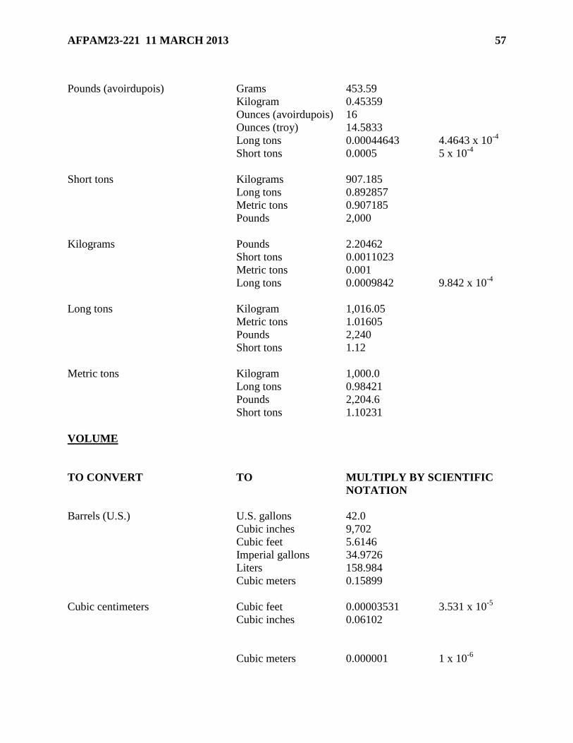
AFPAM23-221 11 MARCH 2013 57
Pounds (avoirdupois) Grams 453.59
Kilogram 0.45359
Ounces (avoirdupois) 16
Ounces (troy) 14.5833
Long tons 0.00044643 4.4643 x 10⁻⁴
Short tons 0.0005 5 x 10⁻⁴
Short tons Kilograms 907.185
Long tons 0.892857
Metric tons 0.907185
Pounds 2,000
Kilograms Pounds 2.20462
Short tons 0.0011023
Metric tons 0.001
Long tons 0.0009842 9.842 x 10⁻⁴
Long tons Kilogram 1,016.05
Metric tons 1.01605
Pounds 2,240
Short tons 1.12
Metric tons Kilogram 1,000.0
Long tons 0.98421
Pounds 2,204.6
Short tons 1.10231
VOLUME
TO CONVERT TO MULTIPLY BY SCIENTIFIC
NOTATION
Barrels (U.S.) U.S. gallons 42.0
Cubic inches 9,702
Cubic feet 5.6146
Imperial gallons 34.9726
Liters 158.984
Cubic meters 0.15899
Cubic centimeters Cubic feet 0.00003531 3.531 x 10⁻⁵
Cubic inches 0.06102
Cubic meters 0.000001 1 x 10⁻⁶

58 AFPAM23-221 11 MARCH 2013
Cubic yards 0.000001308 1.308 x 10⁻⁶
Gallons (US liquid) 0.0002642
Liters 0.001
Pints (US liquid) 0.002113
Quarts (US liquid) 0.001057
Cubic feet Cubic Centimeters 28,316.9
Cubic inches 1,728
Cubic meters 0.02832
Cubic yards 0.03704
Gallons (US liquid) 7.48052
Liters 28.32
Pints (US liquid) 59.84
Quarts (US liquid) 29.92
Cubic inches Cubic Centimeters 16.39
Cubic feet 0.0005787 5.787 x 10⁻⁴
Cubic meters 0.00001639 1.639 x 10⁻⁵
Cubic yards 0.00002143 2.143 x 10⁻⁵
Cubic gallons 0.004329
Liters 0.01639
Mil feet 106,000 1.061 x 10⁵
Pints (US liquid) 0.03463
Quarts (US liquid) 0.01732
Cubic meters Bushels (dry) 28.38
Cubic centimeters 1,000,000 1 x 10⁶
Cubic feet 35.31
Cubic inches 61,023.74
Cubic yards 1.308
Gallons (US liquid) 264.2
Liters 1,000
Pints (US liquid) 2,113.4
Quarts (US liquid) 1056.7
Cubic yards Cubic centimeters 764,554.97 645549 x 105
Cubic feet 27
Cubic inches 46,656
Cubic meters 0.7646
Cubic gallons 202
Liters 764.6
Pints (US liquid) 1,615.8
Quarts (US liquid) 807.9
Gallons (Imperial) Cubic inches 277.42
Cubic feet 0.160544

AFPAM23-221 11 MARCH 2013 59
US gallons 1.200954
US barrels 0.028594
Liters 4.546
Cubic meters 0.004546
Gallons (US) Cubic centimeters 3,785.4
Cubic feet 0.1337
Cubic inches 231
Cubic meters 0.003785
Cubic yards 0.004951
Liters 3.785
Pints 8
Quarts 4
Liters Bushels (US dry) 0.02838
Cubic centimeters 1,000
Cubic feet 0.03531
Cubic inches 61.02
Cubic meters 0.001
Cubic yards 0.001308
Gallons (US liquid) 0.2642
Pints (US liquid) 2.113
Quarts (US liquid) 1.057
NOTE: See figure 1 for fuel factors and figure 2 for ocean tanker capacities.
Figure A6.1. VOLUME CAPACITY FOR ONE FOOT OF HOSE/PIPE.
Formulas -
C = capacity in gallons
D = diameter
L = length
When measurements are in
inches -
C = D x D x 0.7854 x L
231
Example - 2" x 2" x 0.7854 x 12" = 37 ÷ 231 = 0.1632 gallons
When measurements are in feet -
SIZE
DIAMETER
OF HOSE/PIPE
GALLON CAPACITY
IN A
1-FOOT LENGTH
1-inch 0.0408
1½-inch 0.0918
2-inch 0.1632
2½-inch 0.2550
3-inch 0.3672
4-inch 0.6528
6-inch 1.4688

60 AFPAM23-221 11 MARCH 2013
C = D x D x 0.7854 x L x 7.48
Example - 0.1666 x 0.1666 x 0.7854 x 1 x 7.48 = 0.1631 gallons
FUEL FACTORS
POUNDS BARRELS BARRELS BARRELS
PER PER PER PER
PRODUCT BARRELS LONG TON METRIC TON SHORT TON
______________________________________________________________________________
JP-5 286.86 7.809 7.686 7.686
JP-8 281.95 7.945 7.818 7.094
Jet A 281.95 7.945 7.818 7.094
Jet A-1 281.95 7.945 7.818 7.094
JPTS 276.75 8.094 7.966 7.227
100LL 250.49 8.943 8.801 7.984
MGR 260.74 8.599 9.410 7.678
Kerosene 285.18 7.854 7.730 7.013
DFA 283.58 7.900 7.774 7.053
DF2 293.66 7.628 7.508 6.811
DFM 295.43 7.582 7.462 6.770
FO-1 284.38 7.877 7.752 7.033
FO-2 296.31 7.560 7.440 6.750
FO-4 319.91 7.002 6.891 6.252
FO-5 (light) 333.94 6.708 6.602 5.999
FO-5 (heavy) 336.31 6.663 6.557 5.949
FO-6 341.80 6.554 6.450 5.851
Navy Special 331.04 6.766 6.660 6.041
OCEAN TANKER CAPACITIES
DESIGN CAPACITY
OF CAPABILITY OF CARGO
TANKER DESCRIPTION (BBLS)
T-AO Shuttle Oilers 180,000
T-AOE Station Oilers 177,000
T-1 Shallow Draft Tanker 36,000
T-5 Tanker (CONSOL Capable) 235,000

AFPAM23-221 11 MARCH 2013 61
Attachment 7
AIRCRAFT PLANNING FACTORS
A7.1. AIRCRAFT PLANNING FACTORS The following factors are for contingency or
exercise planning only. Fuel and LOX quantities are averages. Actual consumption varies due
to mission profile. Helicopter length is the length of the fuselage, while the span is the main
rotor diameter. All fuel quantities are in US gallons. Normal load indicates the normal aircraft
capacity, excluding ferry tanks. Reference numbers are to notes at the end of this section.
NOTE: Fuel grades are for planning purposes only. This publication does not constitute
authority to use a grade of fuel other than specified for a particular aircraft. Official aircraft
consumption factors are prescribed in AFI 65-503, U.S. Air Force Cost and Planning Factors,
Table A13-1, Aviation Fuels Consumption Factors (updated annually). The below numbers are
general planning factors at best. For a more comprehensive list of aircraft sortie rates and fuel
loads please use the Wartime Aircraft Activity (WAA) and the War and Mobilization Plan Vol 5
(WMP-5).
Table A7.1. Aviation Fuels Consumption Factors.
Missio
n
Desig
n
NOR
M
SPA
N
LENGT
H
Series
(MDS
)
NAME LOA
D
FT-
IN
FT
-IN
A-3 Skywarrio
r
4,390 72-6 76-4
A-6E Intruder 2,320 59-5 54-7
A-10 Thunderbo
lt
1,644 57-6 53-4
A-37 Dragonfly 1,150 35-11 28-3
AH-1 Cobra 93 259 44-0 44-6
AH-64 Apache 375 48-0 48-2
AV-
8A
Harrier 760 25-
3
45-
6
B-1B Lancer 30,84
2
136
-9
147
-0
B-2 Spirit 25,37
3
172
-0
69-
0
B-52H Stratofort 46,63
0
185-0 160-
0
B-707-
300C
23,88
5
145-9 152-
11
B-727 7,680 108
-0
153
-2

62 AFPAM23-221 11 MARCH 2013
B-747-
100F
51,00
0
195-8 231-
4
B-747-
200
51,43
0
195-8 231-
4
B-747-
400F
53,98
5
231-4 231-
4
B-757-
200F
11,27
6
124-8 155
C-5 Galaxy 53,08
3
222
-9
247
-10
C-9 Nightingal
e
5,492 93-5 119-
4
C-12 Super
King
250 54-6 43-9
C-17 Globemast
er
27,02
4
170-0 175.
2-0
C-20A Gulfstrea
m
1,700 777-10 83-1
C-21 Learjet 35 500 39-6 48-8
C-23 Sherpa 500 74-
8
58-
1
C-130 Hercules 6,662 132-7 97-9
C-131 Samaritan 1,730 105-4 79-2
CH-21 Shawnee 300 44-0 52-7
CH-34 Choctaw 262 56-0 46-9
CH-37 Mojave 398 72-0 64-
11
NOR
M
SPA
N
LENGTH
MDS NAME LOA
D
FT-IN FT-
IN
CH-53 Stallion 628 27-7 73-4
CH-54 Skyhook 1,350 72-0 88-0
CT-39 Sabreliner 610 44-5 43-9
DC-8-
50/61
23,39
3
148-5 187-
5
DC-8-
62/63
24,27
5
148-5 187-
5
DC-9-
301
3,679 93-5 125-
7
DC-
10-
20CF
26,50
0
165-4 182-
0
DC-
10-
36,00
0
165-4 182-
0

AFPAM23-221 11 MARCH 2013 63
30CF
E-2 Hawkeye 1,784 80-7 57-7
E-3A Sentry 23,85
5
145
-9
152
-11
E-4 NAOC 51,30
0
195
-8
231
-4
E-8 Joint Star 23,85
5
145-9 152-
11
EA-6B Prowler 3,798 53 59
EC-
135
Stratolift
er
31,20
0
130-
10
136
-3
EF-
111
Raven 2,800 63-0 73-6
F-4 Phantom 1,889 38-8 63-0
F-5 Tiger II 680 26-8 48-6
F-8 Crusader 1,493 54-6 35-8
F-14 Tomcat 2,400 64-1 62-0
F-15 Eagle 2,400 42-
10
63-
9
F-15E Eagle 3,000 42-
8
63-
8
F-16 Falcon 1,072 32-
10
49-
6
F-18 Hornet 1,597 37-
6
56-
0
F-22 Raptor 2,500 44-
6
62-
1
F-104 Starfighter 1,400 21-11 54-9
F-117 Nighthaw
k
1,158 43-0 65-
11
H-47 Chinook 630 12-5 51-0
HH-1 Iroquois 220 48-0 39-8
HH-2 Seasprite 274 44-0 38-4
HH-3 Pelican 685 57-
3
61-
0
HH-
3E
Jolly
Green
685 57-3 62-0
HH-21 Workhors
e
300 44-0 52-7
HH-53 Super
Jolly
305 72-3 67-2
HH-
60D
Night
Hawk
362 53-8 50-
1
KC-10 Extender 5200
0
165-4 181-
7
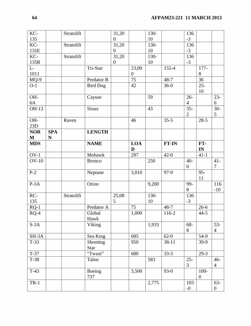
64 AFPAM23-221 11 MARCH 2013
KC-
135
Stratolift 31,20
0
130-
10
136
-3
KC-
135E
Stratolift 31,20
0
130-
10
136
-3
KC-
135R
Stratolift 31,20
0
130-
10
136
-3
L-
1011
Tri-Star 23,00
0
155-4 177-
8
MQ-9 Predator B 75 48-7 36
O-1 Bird Dog 42 36-0 25-
10
OH-
6A
Cayuse 59 26-
4
23-
6
OH-13 Sioux 43 35-
2
30-
5
OH-
23D
Raven 46 35-5 28-5
NOR
M
SPA
N
LENGTH
MDS NAME LOA
D
FT-IN FT-
IN
OV-1 Mohawk 297 42-0 41-1
OV-10 Bronco 250 40-
0
41-
7
P-2 Neptune 3,010 97-9 95-
11
P-3A Orion 9,200 99-
8
116
-10
RC-
135
Stratolift 25,08
5
130-
10
136
-3
RQ-1 Predator A 75 48-7 26-6
RQ-4 Global
Hawk
1,000 116-2 44-5
S-3A Viking 1,933 68-
8
53-
4
SH-3A Sea King 685 62-0 54-9
T-33 Shooting
Star
950 38-11 39-9
T-37 “Tweet” 680 33-3 29-3
T-38 Talon 583 25-
3
46-
4
T-43 Boeing
737
3,500 93-0 100-
0
TR-1 2,775 103
-0
63-
0

AFPAM23-221 11 MARCH 2013 65
U-1A Otter 214 58-
0
41-
10
U-2 Dragon
Lady
2,775 103-0 63-0
U-3A Cessna
310
130 36-11 36-0
U-6A Beaver 95 48-
0
30-
5
U-8 Seminole 230 45-3 31-6
U-11 Aztec 144 37-
3
31-
3
U-21 UTE
UH-1 Iroquois 220 48-0 39-8
UH-10 Chicasaw 175 53-0 42-3
UH-
60A
Blackha
wk
362 53-8 50-
1
US-3A Viking 1923 68-
8
53-
4
Table A7.2. Fuels for USAF Reciprocating Engine Aircraft.
A7.2. TURBOJET AND TURBOPROP AIRCRAFT. Primary, alternate, and emergency fuel
for all turbojet and turboprop engines installed in USAF aircraft will be called out in the
designated aircraft - 1 flight manual. As referenced; in order of decreasing precedence, fuel for
USAF aviation applications (less the U-2) is as follows:
A7.2.1. JP8/JP5
A7.2.1.1. JET AM
/JET A-1 (with SDA, FSII, and CI)
A7.2.1.2. JP4/Jet B (with SDA, FSII, and CI)
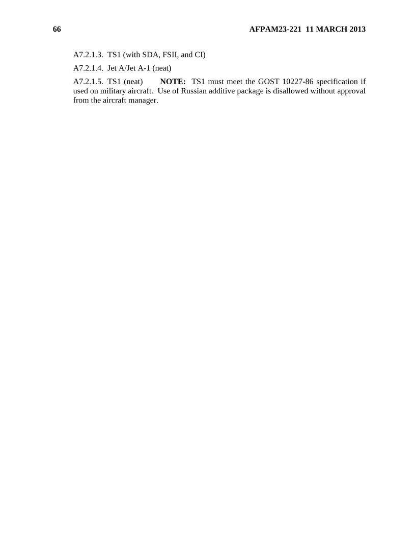
66 AFPAM23-221 11 MARCH 2013
A7.2.1.3. TS1 (with SDA, FSII, and CI)
A7.2.1.4. Jet A/Jet A-1 (neat)
A7.2.1.5. TS1 (neat) NOTE: TS1 must meet the GOST 10227-86 specification if
used on military aircraft. Use of Russian additive package is disallowed without approval
from the aircraft manager.

AFPAM23-221 11 MARCH 2013 67
Attachment 8
EQUIPMENT AND MANPOWER DECISION LOGIC
A8.1. EQUIPMENT AND MANPOWER DECISION LOGIC. The following decision logic
table is designed to provide suggested equipment and personnel required to support a particular
scenario. Choose the servicing requirement in the top chart. Then refer to the bottom chart for
the appropriate support package. THIS IS A GUIDE ONLY! Tailor the requirements to fit
individual and mission needs. NOTE: Systems below do not include bladders in slings.
Table A8.1. Equipment Requirements Decision Logic Table.
POL Equipment Requirements Decision Logic Table
Thousands of Gallons Per Day
100 200 300 400 500 600 700 800 900 1000
FORCE Starter JFDFS 1 1 1 1 2 2 2 2 3 3
FORCE Receipt
Capability
JFDRC 1 1 1 1 2 2 2 2 3 3
FORCE Additional
Servicing Capability
JFDSC 0 0 0 1 0 0 1 2 0 1
R-22 600 GPM pump JFDEJ 0 1 2 0 0 2 1 0 2 1
FFU-15E Filter Vessel JFDEP 0 1 1 0 0 1 1 0 2 1
PMU-27 50 GPM pump JFDEK 1 1 1 2 2 2 3 3 3 4
Hose Kit JFDHL 1 1 1 1 2 2 2 2 2 3
R-18s 3 3 3 5 6 6 8 10 9 11
R-19s 2 2 2 4 4 4 6 8 6 8
R-20s 1 1 1 3 2 2 4 6 3 5
Table A8.2. Manpower Requirements Decision Logic Table.
POL Manpower Requirements Decision Logic Table
Thousands of Gallons Per Day
50 100 150 200 250 300 350 400 450 500
POL Fuels 9 LVL Manager JFA9M 0 0 0 0 0 0 1 1 1 1
POL Fuels 7 LVL Supervisor JFA7M 1 1 1 1 1 1 1 1 1 2
POL Fuels 7 LVL Supervisor JFA7S 1 2 2 3 3 3 2 2 3 3
POL Augmentation Package JFABA 1 2 0 2 1 2 3 2 3 4
POL Fuels Building Block PKG JFABB 0 0 2 1 2 2 2 3 3 3
POL Cryogenics Maintenance JFACM 0 0 0 0 0 0 0 0 0 0
POL Fuels Resource Controllers JFARC 1 1 1 1 1 1 1 1 1 1
POL Refueling Equipment Mgr JFARM 1 1 1 1 2 2 2 2 2 2

68 AFPAM23-221 11 MARCH 2013
POL Fuels Specialty Acct JFASA 1 1 1 1 1 1 1 1 1 1
POL Fuels Specialty Lab JFASL 1 1 1 1 1 1 2 2 2 2
POL FSE Setup Team JFAFS 1 1 1 1 1 1 1 2 2 2
Pax Total 13 17 21 23 26 29 33 38 42 46
4 4 2 3 3 4 5 4 4 5
POL Manpower Requirements Decision Logic Table Continued
Thousands of Gallons Per Day
550 600 650 700 750 800 850 900 950 1000
POL Fuels 9 LVL Manager JFA9M 1 1 1 1 1 1 1 1 1 1
POL Fuels 7 LVL Supervisor JFA7M 2 2 2 2 2 3 3 3 3 3
POL Fuels 7 LVL Supervisor JFA7S 3 3 3 4 4 3 4 4 4 4
POL Augmentation Package JFABA 4 5 5 6 6 7 8 8 9 9
POL Fuels Building Block PKG JFABB 4 4 5 5 6 7 7 8 8 9
POL Cryogenics Maintenance JFACM 0 0 0 0 0 0 0 0 0 0
POL Fuels Resource Controllers JFARC 1 2 2 2 2 2 2 2 2 2
POL Refueling Equipment Mgr JFARM 2 3 4 4 4 4 4 5 5 5
POL Fuels Specialty Acct JFASA 1 2 2 2 2 2 2 3 3 3
POL Fuels Specialty Lab JFASL 2 3 3 3 3 3 3 3 3 4
POL FSE Setup Team JFAFS 2 2 2 3 3 3 4 4 4 4
Pax
Total
51 59 65 72 77 85 92 99 102 108
8 6 7 5 8 7 7 3 6 8

AFPAM23-221 11 MARCH 2013 69
Attachment 9
INTERSERVICE FUELS EQUIPMENT AND SYSTEMS
A9.1. USAF FUEL SUPPORT EQUIPMENT AND SYSTEMS.
A9.1.1. Aerial Bulk Fuel Delivery Systems (ABFDS)
A9.1.1.1. Primary Function - Bulk haul of fuel onboard C-130, C-17, and C-5 aircraft.
A9.1.1.2. Alternate Function - Ground refueling of aircraft in forward areas when the
Alternate Capabilities Equipment (ACE) kit is installed.
A9.1.1.3. Manufacturers - Air Logistics, NSN - 4930-833-4393, T.O. 37A9-3-7-1;
Engineered Air Systems, NSN - 4930-01-388-9490, T.O. 37A9-3-16-1
A9.1.1.4. Standard Aircraft Configurations -
A9.1.1.4.1. Aircraft # 3K Bladders Total Capacity
A9.1.1.4.2. C-130 Two 6,000 gallons
A9.1.1.4.3. C-17 Three 9,000 gallons
A9.1.1.4.4. C-5 Ten 30,000 gallons
A9.1.1.5. Pump Capacity - Two 600 GPM pumps. The pumps may be operated
separately or concurrently. Maximum issue rate with ACE is 350 GPM.
A9.1.1.6. Issue Nozzle - Single Point Refueling, 2.5 inch.
A9.1.1.7. Issue KAM-LOK Coupler - 4 inch male, 4 inch female, 3 inch female.
A9.1.1.8. Refill Connections - 4 inch female KAM-LOK, Single Point Refueling 2.5
inch adapter.
A9.1.1.9. Airlift Data - Each 3,000 gallon bladder is mounted on a 240 inch long by 108
inch wide platform. Platforms may be stacked for shipment when transported as cargo.
Both pumps and the ACE kit, when installed, are secured to a single 88 inch long by 108
inch wide 463L pallet. UTC - JFABF (2 personnel), JFDEY (Equipment One ABFDS
w/ACE), JFDEW (Equipment One ABFDS).
A9.1.1.10. Platform Size - 88L x 108W x 30H Shipping Weight = 6400 lbs.
A9.1.1.11. Operation and Installation -
A9.1.1.11.1. Two AFSC 2F0X1 Special Experience Identifier (SEI) 369 qualified
ABFDS operators are required for operation of the ABFDS or ABFDS with ACE.
The aerial fuel delivery standard configuration utilizes all pallet positions inside the
aircraft cargo compartment, to include the ramp position. The number of fuel
bladders may be reduced due to mission requirements. The pump module must be
located on the aft ramp during engine operation to permit engine exhaust hoses to
extend outboard of the cargo compartment.
A9.1.1.11.2. Some ABFDS have been modified with Alternate ACE to provide a
capability to refuel aircraft direct from the ABFDS. Commanders may authorize the
one-time use of non-ACE equipped ABFDS for aircraft servicing when an emergency
70 AFPAM23-221 11 MARCH 2013
situation develops and support cannot be provided by other means. Under these
circumstances, it must again be remembered that the normal ABFDS has no filter
separator capability.
A9.1.1.11.3. Interoperability - The ABFDS is versatile in its capability to interface
with other equipment. ABFDS can be used for delivery of all grades of jet fuels, Av-
Gas, diesel or heating fuels, and gasoline. The system can deliver fuel to all other
services, road tankers, bulk fuel storage systems, and aircraft except the UH-1 and
OH-58 helicopters. Advance notice is required for US Air Force to obtain the CCR
nozzle or open port nozzle for refueling the UH-1 and OH-58 helicopters. The
ABFDS can also receive fuel from the USA Fuel System Supply Point (FSSP),
Tactical Airfield Fuel Dispensing System (TAFDS), and all road tankers.
A9.1.2. FORCE
A9.1.2.1. Primary Function - Fuel receipt, bulk fuel storage, and transfer, truck fillstand
and aircraft refueling system.
A9.1.2.2. FORCE is comprised of three distinct UTCs: JFDFS, JFDRC, and JFDSC
(See Attachment 8).
A9.1.2.3. Description - When used in conjunction with fabric fuel bladders, it provides a
deployable, above-ground, constant pressure, flow on demand fueling system for aircraft,
i.e., a Type III hydrant fueling system. A typical equipment arrangement to perform the
hydrant mission uses three R-18s (Pumping Unit), three R-19s (Filter Separator Unit),
three R-20s (Servicing Platform), and hoses, fittings, and components from the R-21
(Plumbing Assembly) capable of providing up to 2,700 gpm directly to receiver aircraft,
please note that FORCE does not have a standard foot print. It is all determined by your
daily fuel requirement and any host nation specific requirements. A single system is
capable of providing 400,000 gallons per day sustained and up to 1 million gallons a day
surge capability. The R-18s and R-20s communicate with each other through a wired
remote control system, and each R-18 and R-20 has a hand-held remote control
capability, which communicates by wire (tether) with its respective unit. The control
system is capable of integrating up to ten R-18 Pumping Units and ten R-20 Servicing
Platforms in a hydrant-type arrangement. Additionally, each FORCE system is equipped
with a R-18 pump, R-19 filter separator, line strainer, two offloading skids capable of
receiving from 4 tank trucks simultaneously, meter, hose, and couplings to offload fuel
from a remote location outside the base perimeter fencing. Lastly, FORCE has one R-18
designed to transfer fuel from a bulk storage location to operating storage at rates of 900
GPM or more.
A9.1.2.4. Tank Capacity - FORCE can be configured with any size and number of
bladder storage tanks or tied directly into a bulk storage system.
A9.1.2.5. Pump Capacity - 600 gpm through a single issue nozzle and 900 gpm through
two issue nozzles (servicing platform), Single Point Refueling 2.5 inch and Open Port 2
inch issue
A9.1.2.5.1. Couplers (R-18) - one 6 inch male Camlock fitting
A9.1.2.5.2. Receipt couplers (R-18) - two 6 inch four ear Camlock fittings

AFPAM23-221 11 MARCH 2013 71
A9.1.2.5.3. Airlift Data - Is contained in the LOGDET.
A9.1.2.6. Components and Operation - The R-18 is a pumping system powered by a
multi-fuel engine capable of moving 900 gpm of jet fuel at an output pressure of 150 psi.
The pump end is a self- priming centrifugal pump driven by a speed-increasing gear box
attached to the engine. A pressure relief valve, which is located in a by-pass circuit
around the pump, ensures that the system pressure is no more than 150 psi and also
protects the pump from upstream pressure surges. Additionally, the pump is equipped
with an air eliminator to automatically prevent vapor locks when offloading tank trucks.
The inlet connections are two six-inch female, four-ear Camlock fittings. The outlet is a
six-inch male Camlock fitting. An eight-inch basket strainer is upstream of the pump
impellers to prevent impeller damage. A locking wafer valve is upstream of the basket
strainer, so that the basket strainer may be isolated for cleaning with minimal draining of
fuel required. A telescoping hoist provides area lighting from four halogen flood lights.
The remote control system includes a hand-held controller which can be used to start and
stop the unit and change the engine rpm from idle to run and back again. The hand-held
unit can be either tethered or use Radio Frequency depending on the operator’s choice.
There is also a wired communications capability, so that the R-18 can work in concert
with other R-18s and R-20s. Programmable logic controllers (PLCs) are used to control
the unit’s functions based on communications received from the hand-helds and/or other
R-18s and R-20s. The trailer-mounted R-20 weighs about 4,600 pounds. The R-19
consists of two 600 gpm aluminum alloy filter separators, which are fully qualified to the
requirements of API/IP 1581, Fifth Edition, and configured to run in parallel at 1200 gpm
or individually at 600 gpm. Each 600 gpm filter separator is qualified to the M100
requirements with the additional military requirements for reduced effluent-free water
limit. Each vessel incorporates a peak holding differential pressure gauge and is fitted
with a pressure relief valve and an air eliminator that have discharge ports connected to a
sump tank. The sump tank is equipped with an evacuation system that discharges the
accumulated fuel back into the inlet of the filter separator system. Each filter separator is
equipped with a two-inch manual water sump drain system. The sumps of each vessel
are fitted with a float pilot, which shuts down the flow through the vessel when the sump
reaches a predetermined water level. Each vessel has a four-inch isolation
valve/evacuation system so that the filter vessel can be drained and filter elements can be
changed in either vessel while maintaining flow through the other without having to drain
any of the fuel to a container. Four-inch inlets to the two filter separators are connected
by a manifold to a single six-inch inlet having a female, four-ear, Camlock fittings. The
outlet of each vessel has a control valve that is piloted to - (1) stop the flow in the event
of a high water level in the vessel’s sump; (2) limit the flow to a maximum of 660 gpm
through the vessel; and (3) check flow in the reverse direction. The four-inch outlets of
the two filter separators are connected by a manifold to a single six-inch, male Camlock
outlet. The trailer mounted R-19 weighs about 3,000 pounds. The R-20 supplies up to
900 gpm of fuel to two aircraft and limits nozzle pressure to 50/or 35 +/- 5 psi. The fuel
inlet to the platform is a six-inch, four-ear, female Camlock. A 1-micron filter, which is
rated for 1000 gpm, provides the final filtering of the fuel before it enters the aircraft.
The outlet of the filter vessel is connected to a six-inch control valve that limits the
maximum flow through the system to 1000 gpm under any conditions. This valve also
controls flow through a fluid motor generator, which charges the batteries when fuel is

72 AFPAM23-221 11 MARCH 2013
flowing. Fuel flow is separated through a manifold into two separate circuits capable of
providing up to 600 GPM individually through one hose or 900 GPM through two hoses,
each with its own positive displacement flow meter, pressure and flow control system,
automated data capture (ADC) for collection of billing data and discharge hose and reel.
Electrically operated hose reels with 60 feet of 2.5” API 1529 hose are provided for each
circuit to provide hot pit refueling capability. For fueling of wide body aircraft, two 120-
foot lengths of collapsible 3” hose are stored on manually operated reels and again can
refuel through one hose at 600 GPM or two hoses at 900 GPM. The remote control
system includes a hand-held controller (tethered or RF), which is used to open and close
the fueling valves. There is also a wired communications capability, so that the R-20 can
work in concert with other R-18s and R-20s. Programmable logic controllers (PLCs) are
used to control the unit’s functions based on communications received from the hand-
helds and/or other R-18s and R-20s. The trailer-mounted R-20 weighs about 4,000
pounds.
A9.1.2.7. Interoperability - FORCE, in addition to supporting all US Air Force aircraft,
can refuel all other services/NATO aircraft using the SPR or open port nozzle. The
FORCE system can also receive from and issue fuel to all US Army, US Marine Corps
and NATO road tankers/pipeline systems. There is also 8 bolt 6” ANSI flange to
Camlock connections to allow the system to be used with fixed facilities having an 8 bolt
6” ANSI flange. The system also has two fillstand skids to allow the fill of refueling
vehicles at 50PSI and 600 GPM.
A9.1.2.8. A Mission Readiness Spares Package (MRSP) is available for FORCE.
A9.1.2.9. Refer to AFI 25-101 for FORCE storage/maintenance requirements.
A9.1.3. R-14 Air Transportable Hydrant Refueling System (ATHRS)
A9.1.3.1. Primary Function - Aircraft refueling. Alternate Function includes Aircraft
defuel and unit fillstand.
A9.1.3.2. Description - The R-14 ATHRS has a multi-fuel diesel engine, filter separator,
pressure controls, hoses, nozzles, and adaptors to create a self-contained aircraft refueling
system. Manufacturer - Entwistle, NSN - 4930-00-112-2432, T.O. 37A9-3-5-1/21. The
R-14 ATHRS is not equipped with two 50,000 gallon standard fuel bladders, units must
request additional bladder support if needed.
A9.1.3.3. Tank Capacity - 100,000 gallons in normal configuration. The R-14 can be
configured with any size and number (usually two) of bladder storage tanks or tied
directly into a bulk storage system.
A9.1.3.4. Pump Capacity - 600 GPM
A9.1.3.5. Issue Nozzle - Single Point Refueling 2.5 inch
A9.1.3.6. Issue KAM-LOK Couplers - 4 inch male, 3 inch female.
A9.1.3.7. Receipt KAM-LOK Couplers - 4 inch male, 4 inch female, 3 inch female.
A9.1.3.8. Airlift Data - UTC - JFDEG, Shipping Weight - 10,960 lbs., Cubic Feet - 773,
Overall Dimensions - 156L x 87W x 83-102H.
AFPAM23-221 11 MARCH 2013 73
A9.1.3.9. Operation and Installation - A diked area 80 by 80 feet for bladders
manufactured before 2008 and a diked area 85 x 85 feet for bladders manufactured after
2008 with an interior sand surface area is required to prevent bladder puncture and
spreading of fuel to the parking apron. The dike should be a minimum of 3.5 feet high at
the lowest point to prevent fuel migration. The dike forward area must be within 250 feet
of the receiving aircraft refueling adaptor to permit installation and aircraft refueling with
available hose sections. For more information on building a proper dike area please refer
to T.O. 37A12-15-1. Fuel is normally offloaded into the bladders by use of a 600 GPM
type A/M 32, R-22 pump and a type FFU-15E 600 GPM filter separator. Eighty feet of 4
inch KAM-LOK hose sections and isolation valves are supplied with the A/M 32 R-22
pump. If the R-14 is configured to be tied into an existing storage system, caution must
be exercised to ensure adequate safety precautions are included; i.e., a pumping unit (R-
22), pressure relief valve, and isolation valves are installed between the storage system
and the R-14 unit. When requesting R-14 systems, keep in mind the R-14 is sometimes
described as being complete with two bladder tanks in the slings, while at other times the
bladders are considered completely separate from the pumping unit. Be specific about
the number of pumping units and bladders required.
A9.1.3.10. Interoperability - The R-14, in addition to supporting all US Air Force
aircraft, can refuel all other services’ aircraft using the SPR or open port nozzle. The R-
14 can also receive from and issue fuel to all US Army and US Marine Corps road
tankers through the 4 inch KAM-LOK coupling.
A9.1.4. R-22 Trailer Mounted 600/900 GPM Pump
A9.1.4.1. Primary Function - Provide bulk fuel transfer capability.
A9.1.4.2. Alternate Function - Refuel aircraft when used in conjunction with MH-2
series hosecart or FFU-15E filter separator.
A9.1.4.3. Description - The R-22 is a trailer mounted pumping unit powered by a
multifuel diesel engine, and consists of a 4-cylinder engine, engine housing, basket
strainer, control panel, fuel tank, and accessories. The unit is designed to rapidly and
safely pump large quantities of fuel under any operating condition. The R-22 is usually
used to pump fuel from a bulk storage system to the R-14 bladder tanks.
A9.1.4.4. Manufacturer - Multiple Contractors NSN - 4320-00-131-9185, Multiple T.O.s
provide guidance.
A9.1.4.5. Tank Capacity - None
A9.1.4.6. Pump Capacity - 600 GPM
A9.1.4.7. Issue KAM-LOK Coupler - 6 inch male, 4 inch male.
A9.1.4.8. Receipt KAM-LOK Couplers - 6 inch female, 4 inch Female.
A9.1.4.9. Airlift Data - UTC - JFDEJ Shipping Weight = 2520 lbs. Cubic Feet = 290.
A9.1.4.10. Overall Dimensions - 116L x 69W x 80H
A9.1.4.10.1. Operation and Installation - The R-22 has no filtering or pressure control
system, and thus is not normally authorized for use in servicing aircraft. However, the R-
22 systems have been used effectively in conjunction with MH-2 series hose carts and in

74 AFPAM23-221 11 MARCH 2013
some respects may be superior to a R-14 for providing an immediate fueling capability
where airlift is at a premium. The R-22 through its simplicity is more reliable, lighter,
and easier to operate and maintain than the R-14. The R-22 is designed to transfer fuel at
rates up to 600 GPM. Normally installed at the fill end of 50,000 gallon bladders and
used for off-load from mobile delivery units. Designed for installation in 6 inch pipeline
sections when operating pressures of 150 PSI or less is required. Pressure is reduced to
75 PSI when coupled to 4”hoses.
A9.1.4.11. Accessory Support War Reserve Support Kit - 8 each, 4 inch by 8 foot hoses
with KAM-LOK hose end couplings; 4 each, 4 inch valves equipped with 4 inch KAM-
LOK couplings.
A9.1.4.12. Interoperability - Compatible with other services’ transportable fuel systems.
With appropriate reducers, the pump can be connected with all size KAM-LOK
connectors.
A9.1.5. PMU-27 PUMPING UNIT
A9.1.5.1. Primary Function - Refuel small aircraft and transferring small quantities of
fuel.
A9.1.5.2. Alternate Function - Ground fuels dispensing unit and aircraft defueling.
A9.1.5.3. Description - The PMU-27 is a trailer mounted, engine powered unit consisting
of a 50 GPM pump, filter separator, meter, hoses, connections, and nozzles. It is
designed to support servicing of small aircraft and transfer of small quantities of fuel. It
also is capable of defueling four 55-gallon drums simultaneously, pumping from an
external source and defueling aircraft auxiliary tanks. The unit is also an effective
ground fuels dispensing unit. Manufacturer - Multiple Contractors NSN - 4320-00-754-
7573, T.O. 35E13-73-11/21.
A9.1.5.4. Tank Capacity - None connects to 55 gallon drums, 500 gallon seal drums,
10,000 gallon bladders, etc.
A9.1.5.5. Pump Capacity - 50 GPM
A9.1.5.6. Issue Nozzle - Open Port 1.5 inch.
A9.1.5.7. Issue KAM-LOK Coupler - 1.5 inch male
A9.1.5.8. Receipt KAM-LOK Coupler - 1 ¾ inch female and 2 inch female
A9.1.5.9. Airlift Data - (without support kit) UTC - JFDEK Shipping Weight - 1180 lbs.
A9.1.5.10. Cubic Feet - 94 Overall Dimensions - 100L x 45W x 35H
A9.1.5.11. Operation and Installation - Past experience has shown that PMU-27 units
may not generate sufficient suction to lift fuel from underground tanks. R-22 pumps or
even a C-300 refueling unit may perform this function better. The PMU-27/M is
converted to a service station, for vehicles and equipment when an accessory Non-
Airborne FSE and BEAR Readiness Spares Package (RSP) kit is added.
A9.1.5.12. Accessory Support Non-Airborne FSE and BEAR RSP kit - 4 each, 500
gallon seal drums, 2 each, ¾ inch service station nozzles, 24 feet, ¾ inch discharge hose,

AFPAM23-221 11 MARCH 2013 75
100 feet, 2 inch suction hose, 1 each, 10 GPM hand pump with stand, and 2 tow yokes for
filled 500 gallon seal drums.
A9.1.6. TPI-4T-4 ADDITIVE INJECTOR
A9.1.6.1. Primary Function - Injection of fuel additives into bulk fuel storage.
A9.1.6.2. Alternate Function - None
A9.1.6.3. Description - The additive injector is a skid-mounted module equipped with
two 6 gallon blending tanks. It is capable of injecting three (3) separate additives
simultaneously using three separate injector pumps driven by a common turbine. The
additive injection rates are proportional to the fuel flow rates.
A9.1.6.4. Manufacturer - Hammonds NSN - 4930-01-213-3014, T.O. 37A9-3-15-1
A9.1.6.5. Inlet KAM-LOK Coupler - One 3 or 4 inch female
A9.1.6.6. Outlet KAM-LOK Coupler - One 3 or 4 inch male
A9.1.6.7. Airlift Data - (Crated) UTC - JFDGE Shipping Weight - 365 lbs. Cubic Feet -
22
A9.1.6.8. Overall Dimensions - 49L x 23W x 34H
A9.1.6.9. Operation and Installation - Unit can be installed in-line to a fixed bulk
petroleum system or used in conjunction with truck fillstands, an R-14, or R-22 system or
two systems can be used with the FORCE receiving system but must be used in
conjunction with a pressure reducing valve supplied in the R-21. Fuel System Icing
Inhibitor is drawn from 55 gallon drums and injected in the jet fuel stream along with
corrosion inhibitor and static dissipater additive which are simultaneously drawn from the
two blend tanks.
A9.1.6.10. Interoperability - The additive pump can be used by all services, for injection
of additives provided their equipment and systems can adapt to the pump’s couplers.
A9.1.7. FFU-15E SKID MOUNTED FILTER SEPARATOR
A9.1.7.1. Primary Function - Remove particles and free water from hydrocarbon fuels.
A9.1.7.2. Alternate Function - None
A9.1.7.3. Description - The FFU-15E is a skid-mounted, 600 GPM filter separator,
designed to filter and separate particulate and water from fuel. It is capable of handling
diesel fuel at a rate of 450 GPM, jet fuels and gasoline at a rate of 600 GPM.
A9.1.7.4. Manufacturer - Multiple contractors NSN - 4930-00-935-7328, T.O. 37A8-2-
5-1.
A9.1.7.5. Tank Capacity - N/A
A9.1.7.6. Pump Capacity - 600 GPM
A9.1.7.7. Outlet KAM-LOK Coupler - 4 inch male
A9.1.7.8. Inlet KAM-LOK Coupler - 4 inch female

76 AFPAM23-221 11 MARCH 2013
A9.1.7.9. Airlift Data - UTC JFDEP Shipping Weight - 785 lbs. Cubic Feet - 97 Overall
Dimensions - 66L x 42W x 60H
A9.1.7.10. Operation and Installation - Uses multiple configurations where additional
filtration is required. Normally, used in conjunction with the R-22 Trailer Mounted
Pump.
A9.1.7.11. Interoperability - Can be used with other services’ equipment and systems
which can adapt to the FFU-15E inlet/outlet couplers.
A9.1.8. C-300 GROUND PRODUCTS REFUELER
A9.1.8.1. Primary Function - Ground product refueling.
A9.1.8.2. Alternate Function - Aviation Turbine Fuel, AVGAS and bulk fuel hauling.
A9.1.8.3. Description - Manufacturer - Multiple Contractors. NSN - 2320-01-314-2912,
T.O. 36A12-13-35-1.
A9.1.8.4. Tank Capacity - 1200 gallons
A9.1.8.5. Pump Capacity - 100 GPM
A9.1.8.6. Issue Coupler - 2 ½ inch faucet/over wing type nozzle
A9.1.8.7. Receipt Coupler - 3 inch dry break coupler
A9.1.8.8. Airlift Data - UTC - UFM71-2 x 4/UFM74-4 x 4 Shipping Weight - 13,840
Cubic Feet - 1405 Overall Dimensions - 272L x 96W x 93H
A9.1.8.9. Operation and Installation - The C-300 is designed for operation on hard or
improved surfaces at low to moderate speeds. A 4WD C-301 version of the same vehicle
is also available for use in more austere conditions.
A9.1.8.10. Interoperability - Can refuel any service vehicle/bulk tank with ground fuel
using the over wing nozzle or an optional service station nozzle that can be easily
installed in place of the O/W nozzle. The C-300 can also defuel bulk tanks with the
proper hose configuration.
A9.1.9. R-11 TANK TRUCK AIRCRAFT REFUELER
A9.1.9.1. Primary Function - Aircraft Refueling
A9.1.9.2. Alternate Function - Aircraft defueling and bulk fuel hauling
A9.1.9.3. Manufacturers - Oshkosh/Kovatch NSN - 2320-01-239-5371, T.O. 36A12-13-
17-81
A9.1.9.4. Tank Capacity - 6,000 gallons
A9.1.9.5. Pump Capacity - 600 GPM
A9.1.9.6. Issue KAM-LOK Coupler - SPR 2.5 inch, open port
A9.1.9.7. Receipt KAM-LOK Coupler - Refilled via 2.5 inch SPR bottom loading
adapter.

AFPAM23-221 11 MARCH 2013 77
A9.1.9.8. Airlift Data - UTC - UFM74 Shipping Weight - Oshkosh 26,400 lbs., Kovatch
24,000 lbs. Cubic Feet - Oshkosh 2853.2, Kovatch 2807.4, Overall Dimensions -
Oshkosh 456L x 106 W x 102H Kovatch 447L x 106.4W x 102H
A9.1.9.9. Operation and Installation - The R-11 is designed to be driven on improved
roads and on a limited basis on unimproved roads. Refueler road speed, fully loaded, is
60 MPH, depending on road and weather conditions.
A9.1.9.10. Interoperability - Can refuel other services’ aircraft using the SPR or open
port nozzle. The types of fuel servicing include high-low refueling, low-flow refueling,
and defueling.
A9.1.10. NRU-5E AIR TRANSPORTABLE LIQUID NITROGEN (LN2) SKID
MOUNTED TANK
A9.1.10.1. Primary Function - Aerial and surface transport of LN2 from military and
commercial production plants to operational areas for support of aircraft strut and tire
servicing requirements.
A9.1.10.2. Alternate Function - Bulk storage of LN2
A9.1.10.3. Manufacturer - Multiple Contractors NSN - 3555-01-080-4187, T.O. 37C2-8-
10-3
A9.1.10.4. Tank Capacity - 400 gallons
A9.1.10.5. Issue Coupling - One inch left-handed thread coupling, C8991171
A9.1.10.6. Receipt Coupling - One inch left-handed thread coupling, CC899117.
A9.1.10.7. Airlift Data - UTC - JFDER Shipping Weight - 1,500 lbs. Cubic Feet - 158
A9.1.10.8. Overall Dimensions - 84L x 54W x 60H
A9.1.10.9. Interoperability - Provided with industry standard 1 inch couplings common
to all US commercial and DoD activities.
A9.1.10.10. Accessories - Supplied with a vent kit to connect tanks to the transport
aircraft overboard vent ports.
A9.1.11. TMU-24E AIR TRANSPORTABLE LIQUID OXYGEN (LOX) SKID
MOUNTED TANK
A9.1.11.1. Primary Function - Aerial and surface transport of LOX from military and
commercial production plants to operational areas for support of aviator breathing and
medical oxygen requirements.
A9.1.11.2. Alternate Function - Bulk storage of LOX
A9.1.11.3. Manufacturer - Multiple Contractors NSN - 3655-00-995-8575, T.O. 37C2-8-
10-3
A9.1.11.4. Tank Capacity - 400 gallons
A9.1.11.5. Issue Coupling - One inch right hand thread coupling, C8991173
A9.1.11.6. Receipt Coupling - One inch right hand thread coupling, C8991173

78 AFPAM23-221 11 MARCH 2013
A9.1.11.7. Airlift Data - UTC - JFDEQ Shipping Weight - 1,500 lbs. Cubic Feet - 158
A9.1.11.8. Overall Dimensions - 84L x 54W x 60H
A9.1.11.9. Interoperability - Provided with industry standard 1 inch couplings common
to all US commercial and DoD activities.
A9.1.11.10. Accessories - Supplied with a vent kit to connect tanks to the transport
aircraft overboard vent ports.
A9.1.12. Tactical Automated Service Station (TASS)
A9.1.12.1. Description - The TASS is a deployable tactical fueling station used to
service vehicles and equipment at austere locations throughout the world. The TASS
consists of two 10-gpm electric service station pumps, a generator to supply power for
their operation or capability to connect to a power unit, two dispensing nozzles with hose
reels, AFSS card reader automation, and self contained lighting. The TASS provides a
"self-serve," automated interface with equipment requiring ground fuel. The TASS can
service to different types of fuels or have two nozzles for a single fuel. The TASS is
designed to connect to multiple type fuels source ranging from bladders, portable tanks to
6K gallon trucks via multiple adapters.
A9.1.12.2. Dimensions -
A9.1.12.2.1. Length (in) - 138
A9.1.12.2.2. Width (in) - 95 ½
A9.1.12.2.3. Height- 91 ½
A9.1.12.2.4. Total - 698 cu in
A9.1.12.2.5. Weight (lbs) - 3500
A9.1.12.2.6. Center of gravity:
A9.1.12.2.7. Back to front (in) - 65.7
A9.1.12.2.8. Top to bottom (in) - 31.4
A9.1.12.3. Manufacturer- Porter Manufacturing
A9.1.12.3.1. NSN - 4930-01-521-9141
A9.1.12.4. A MRSP is available for TASS.
A9.1.13. COLLAPSIBLE COATED FABRIC TANKS
A9.1.13.1. Description - Collapsible fuel tanks are normally provided in 10,000, 20,000,
50,000, or 210,000 gallon capacity. Tanks are constructed of a single ply, nylon fabric
material base and five layers of polyurethane with reinforced corners. The interior of the
tank is coated with polyester or Nirtile, while the exterior is of nylon, or equivalent
fabric, impregnated with urethane or nirtile. The weight of a 210,000 gallon tank is
approximately 5,000 pounds. The weight of a 50,000 gallon tank is approximately 1,500
pounds, while the 10,000 gallon tank weighs approximately 375 pounds. Dimensions of
an empty 210K bladder are 70 feet by 70 feet. Dimensions of an empty 50K bladder are
68’ 2” feet by 28’ 1” feet. Dimensions of an empty 10K bladder are 22 feet by 22 feet.

AFPAM23-221 11 MARCH 2013 79
Fabric tanks are tested from - 40 degrees Fahrenheit to 160 degrees Fahrenheit to prove
reliability in any climate. Tanks can be manifolded together and are repairable in the
field. Ref: T.O. 3712-15-1, Chapter 1.4.3.
A9.1.13.2. Considerations - If plans are to use bladders, a suitable site must be selected.
Overall area should be approximately 100 feet wide by 100 feet long for an R-14 system,
be free of rocks and obstructions, and provide adequate drainage. Dike should be placed
as close to the aircraft apron as practically possible. The ground should be as level as
possible with maximum slope of three degrees to prevent the tank from creeping or
crawling. Avoid low areas to prevent accumulation of trapped vapors. Careful attention
should be given to receiving capabilities, such as rail cars, taxiways, and roads. If the site
is dependent on Aerial Bulk Fuel Delivery System for resupply, the tank area must be
placed 100 feet from a parking apron. Do not place the site uphill or upstream from other
installations because of possible contamination or fires due to bladder rupture. Where
possible, a dike or berm should be constructed with a capacity of at least 1 ½ times the
capacity of the tanks within. Collapsible tanks have also been approved for storage of
special fuels (JPTS) with precautions outlined in this pamphlet.
A9.1.13.3. Airlift Data:
A9.1.13.3.1. Designation - 10K Bladder 50K Bladder
A9.1.13.3.2. Shipping wt - 375 lbs. 1,500/1,0261 lbs.
A9.1.13.3.3. Cubic feet - 60 126
A9.1.13.3.4. NSN - SEE T.O. 37A12-15-1 SEE T.O. 37A12-15-1
A9.1.13.3.5. Length (in) - 104 (Rolled) 136 (Rolled)
A9.1.13.3.6. Width (in) - 31 (Rolled) 40 (Rolled)
A9.1.13.3.7. Height (in) - 32 (Rolled) 40 (Rolled)
A9.1.13.3.8. Manufacturer - Uniroyal Belavon, Reliance, MPC1 etc.
A9.1.13.3.9. T.O. - 37A12-15-1 37A12-15-1
A9.1.13.3.10. UTC - JFDEL JFDEM
A9.1.13.3.11. Designation - 210K Bladder
A9.1.13.3.12. Shipping wt - 5,000/42171 lbs
A9.1.13.3.13. Cubic feet 384
A9.1.13.3.14. NSN - SEE T.O.37A12-15-1
A9.1.13.3.15. Length (in) - 192 (Rolled)
A9.1.13.3.16. Width (in) - 72 (Rolled)
A9.1.13.3.17. Height (in) - 48 (Rolled)
A9.1.13.3.18. Manufacturer - Belavon, Reliance, MPC1 etc.
A9.1.13.3.19. T.O. 37A12-15-1
A9.1.13.3.20. UTC - JFDLB

80 AFPAM23-221 11 MARCH 2013
A9.1.14. SEAL DRUMS
A9.1.14.1. Description - Seal Drums are collapsible rubber, non-vented containers for
transporting and storing fuel. Drums are available in 55 or 500 gallon capacities. Drums
are constructed of 4 ply tire cord and are equipped with swivel plates and anchor shackles
at both ends which allow tie down aboard aircraft, and ground towing (rolling) using a
special lifting and towing yoke. Internal tanks are equipped with fuel/defuel valves and
are complete with external fuel servicing adapters.
A9.1.14.2. Considerations - Drums are filled and emptied through an elbow coupler
valve and check valve adapter in the front closure plate. Field repair kits are available.
Because drums are non-vented, they must be kept shaded to prevent fuel expansion and
drum rupture. Below 20 degrees Fahrenheit the drum becomes brittle.
A9.1.14.3. Airlift Data -
A9.1.14.3.1. Designation - 500 Gal. Seal Drum 55 Gal. Seal Drum
A9.1.14.3.2. Shipping Weight - 305 lbs. 27 lbs.
A9.1.14.3.3. Cubic Feet - 93 (full) 6.3 (full)
A9.1.14.3.4. NSN - 8110-00-065-2321 8110-00-8B-5909
A9.1.14.3.5. Length (in) - 72-89 37-38
A9.1.14.3.6. Width (in) - 36-48 24-33
A9.1.14.3.7. Height (in) - 9-48 6-24
A9.1.14.3.8. Manufacturer - US Rubber US Rubber
A9.1.14.3.9. Tech. Order - 37A-1-111 37A-1-111
A9.1.14.3.10. UTC - JFASD JFASD
A9.1.15. HOSE CARTS
A9.1.15.1. Description - MH-2 series hose carts are trailer mounted units designed for
transfer of fuel between fixed hydrant system outlets and single-point refueling
receptacles on aircraft. Carts are equipped with a filter separator, meter, flow control
capability and inlet/outlet hoses. Carts do not have pumping capability. Carts can also
be used to provide filter/meter capability for filling refueling units from hydrant systems,
for bare-base refueling using bladder storage, and R-22 pumping systems; and as a
substitute for the FFU-15 filter separator. The UTC for hose carts is JFZ99.
A9.1.15.2. Considerations - While all hose carts use standardized single-point refueling
nozzles, the hydrant quick-coupler valve (moose head) that connects into the installed
hydrant outlet on the aircraft parking differs, dependent on the type of hydrant outlet
connector in use at an airfield. This is an obvious concern when intending to use Air
Force supplied hose carts on a host airfield. Use of a hose cart in conjunction with an R-
22 pumping system requires removal of the hydrant quick-coupler valve and replacement
with a 4 inch KAM-LOK coupler.
A9.1.15.3. Airlift Data -
A9.1.15.3.1. Designation - MH-2B MH-2C

AFPAM23-221 11 MARCH 2013 81
A9.1.15.3.2. Shipping Weight - 1,700 lbs. 1,760 lbs.
A9.1.15.3.3. Cubic Feet - 377 448
A9.1.15.3.4. NSN - 4930-00-070-1077 4930-01-089-4581
A9.1.15.3.5. Length (in) - 119 138
A9.1.15.3.6. Width (in) - 68 70
A9.1.15.3.7. Height (in) - 80.5 80
A9.1.15.3.8. Pump Capacity -
A9.1.15.3.9. Manufacturer - Garsite Beta
A9.1.15.3.10. Tech Order - 37A2-2-4-41 37A2-2-2-4-71
A9.1.16. JFDAE - Fuels Operations Support Kit (Admin support package)
A9.1.16.1. Description - The Fuels Operation Support Kit is designed to provide Fuels
Management Teams in the field with a 30 day initial capability to support basic Fuels
Operations. Included in the JFDAE kit Admin package is certain forms, fuels technical
data and items found on the local economy.
A9.1.16.2. Required Items - The below items are required at a minimum to be included
in the JFDAE Admin package:
A9.1.16.2.1. AF Form 839 (50 each)
A9.1.16.2.2. DD Form 1898 (1 box)
A9.1.16.2.3. AF Form 1231 (1 each)
A9.1.16.2.4. AF Form 1800 (25 each)
A9.1.16.2.5. AF Form 1807 (25 each)
A9.1.16.2.6. AFTO Form 244/245 (25 each)
A9.1.16.2.7. AFTO Form 39 (50 each)
A9.1.16.2.8. AFTO Form 4427 (25 each)
A9.1.16.2.9. T.O. 00-25-172 (to include applicable checklist)
A9.1.16.2.10. AFI 23-201
A9.1.16.2.11. AFPAM 23-221
A9.1.16.2.12. D Batteries (12 each)
A9.1.16.2.13. 550 Cord (100 ft)
A9.1.16.2.14. Rubber Gloves (2 pair)
A9.1.16.2.15. Safety Goggles (2 each)
A9.1.16.2.16. Portable Eye Wash Bottles (2 each)
A9.1.16.2.17. 50 ft Extension Cords (2 each)
A9.1.16.2.18. General Spill Kit (2 each)

82 AFPAM23-221 11 MARCH 2013
A9.1.17. JFDEC - Fuels Cryogenic Support Kit (Admin support package)
A9.1.17.1. Description - The Fuels Cryogenic Support Kit is designed to provide Fuels
Management Teams in the field with a 30 day initial capability to support basic Fuels
Cryogenic Operations. Included in the JFDEC kit Admin package is certain forms, fuels
technical data and items found on the local economy.
A9.1.17.2. Required Items - The below items are required at a minimum to be included
in the JFDEC Admin package.
A9.1.17.2.1. AFTO Form 244 (5 each)
A9.1.17.2.2. AFTO Form 245 (5 each)
A9.1.17.2.3. AFTO Form 95 (5 each)
A9.1.17.2.4. T.O. 37C2-8-28-1
A9.1.17.2.5. T.O. 37C2-8-28-1CL-1
A9.1.17.2.6. T.O. 37C2-8-1-116WC-1
A9.1.17.2.7. T.O. 42B6-1-1
A9.1.17.2.8. LOX Over boots (3 pair)
A9.1.17.2.9. 100% Cotton Blanket (1 each)
A9.1.17.2.10. Safety Goggles (2 each)
A9.1.17.2.11. Face Shields (2 each)
A9.1.18. JFDAL - Fuels Laboratory Support Kit (Admin support package)
A9.1.18.1. Description - The Fuels Laboratory Support Kit is designed to provide Fuels
Management Teams in the field with an initial 30 day laboratory support capability.
Included in the JFDAL kit Admin package is certain forms, fuels technical data and items
found on the local economy.
A9.1.18.2. Required Items - The below items are required at a minimum to be included
in the JFDAL Admin package.
A9.1.18.2.1. AFTO Form 150 (25 each)
A9.1.18.2.2. AFTO Form 475 (10 each)
A9.1.18.2.3. T.O. 42B-1-1
A9.1.18.2.4. Chem Wipes (6 boxes)
A9.1.18.2.5. Rubber Gloves (2 pairs)
A9.1.18.2.6. Safety Goggles (2 each)
A9.1.18.2.7. Nitrile Gloves (2 boxes)
A9.2. US Army Refueling Equipment and Systems.
A9.2.1. Advanced Aviation Forward Area Refueling System (AAFARS)
A9.2.1.1. Primary Function - Refuel four helicopters simultaneously.
AFPAM23-221 11 MARCH 2013 83
A9.2.1.2. Tank Capacity - No fuel storage is organic to the AAFARS. Generally,
normally four-500 gallon collapsible drums are used as a source of supply; however, the
AAFARS has adapters to connect to any fuel source which can be accessed through a 2,
3, or 4-inch Camlock couplings.
A9.2.1.3. Pump Rate - 220 GPM pump
A9.2.1.4. Issue Nozzles - D-1, CCR or GFA (CCR nozzle assembly and Gravity Fill
Adapter for open port fueling)
A9.2.1.5. Issue Couplers - N/A
A9.2.1.6. Receipt Couplers - 2, 3, and 4-inch KAM-LOK
A9.2.1.7. Airlift Data - 1,726 lbs. (storage tanks not included)
A9.2.1.8. NSN - 4930-01-380-4856
A9.2.1.9. UTC - N/A
A9.2.1.10. Operation and Installation - The AAFARS system consists of a 220 GPM
pump assembly (with diesel engine), a 240 GPM filter separator, 6-feet of 2-inch suction
hose, 50 feet of 3-inch discharge hose, 100-feet of 2-inch discharge hose per nozzle, 4-ea.
D-1, CCR (closed circuit refueling nozzles) GFR (with open port adapters), and various
fittings.
A9.2.1.11. Interoperability - The AAFARS (refueling rate with all four nozzles is 55
GPM per nozzle or 90 GPM at one nozzle) can use USMC or USAF collapsible tanks as
a source of fuel as well as USMC tank trucks. However, to source fuel from a USAF
tank truck, advance coordination is required with the USAF to ensure a SPR nozzle with
KAM-LOK coupling is available. The AAFARS can be used to refuel other Services'
aircraft which will accept D-1, CCR or open port nozzles refueling.
A9.2.2. Forward Area Refueling Equipment (FARE) System
A9.2.2.1. Primary Function - Refuel helicopters in forward areas.
A9.2.2.2. Alternate Functions - Refuel ground vehicles, fill fuel cans, and drums.
A9.2.2.3. Tank Capacity - No fuel storage is organic to the FARE. Generally, 500 gallon
collapsible drums are used as a source of supply; however, the FARE has adapters for
sourcing from collapsible tanks (2-4-inch KAM-LOK) or tank vehicles (2-3-inch KAM-
LOK).
A9.2.2.3.1. Pump Rate - 100 GPM.
A9.2.2.3.2. Issue Nozzles - CCR nozzles with open port nozzle adapter
A9.2.2.3.3. Issue Couplers - N/A
A9.2.2.3.4. Receipt Couplers - 2, 3, and 4-inch KAM-LOK
A9.2.2.3.5. Airlift Data - 820 lbs. (storage tanks not included)
A9.2.2.3.6. NSN - 4930-00-133-3041
A9.2.2.3.7. UTC - N/A
84 AFPAM23-221 11 MARCH 2013
A9.2.2.4. Operation and Installation - The FARE system consists of a 100 GPM pump
assembly (with gasoline engine), a 100 GPM filter separator, 50-feet of 2-inch suction
hose, 200-feet of 2-inch discharge hose, 2 closed circuit refueling nozzles (with open port
adapters), and various fittings.
A9.2.2.5. Interoperability - The FARE can use USMC or USAF collapsible tanks as a
source of fuel as well as USMC tank trucks. However, to source fuel from a USAF tank
truck, advance coordination is required with the USAF to ensure a SPR nozzle with
KAM-LOK coupling is available. The FARE can be used to refuel other Services'
aircraft which will accept CCR or open port nozzles. When used as a refueling point for
ground vehicles, the FARE can refuel any Services' ground equipment.
A9.2.3. Extended Range Fuel System (ERFS) also Fat Cow
A9.2.3.1. Primary Function - CH-47 Extended Range Fuel System (ERFS) also known
as the Fat Cow is used to extend aircraft range.
A9.2.3.2. Alternate Functions - Forward Area Refueling Source
A9.2.3.2.1. Tank Capacity - Using four-600 gallon non-crashworthy tanks as a
source of supply
A9.2.3.2.2. Pump Rate - (Electric 100 GPM Pumping Assembly) 100-250 GPM
pump
A9.2.3.2.3. Filter Separator - 100 GPM (Same as used with FARE)
A9.2.3.2.4. Issue Nozzles - D-1 or CCR
A9.2.3.2.5. Issue Couplers - Camlock or Unisex
A9.2.3.2.6. Receipt Couplers - Can be pressure refueled (maximum 35 psi and 150
GPM) using the D-1 or Open port refueling nozzle.
A9.2.3.2.7. Airlift Data - 3,770 lbs. (four tanks filled) 2,320 gallons (850 gallons per
tank).
A9.2.3.2.8. NSN - 1560-01-221-7600
A9.2.3.2.9. UTC - N/A
A9.2.3.3. Operation and Installation - The ERFS consists of four-600-gallon tanks with a
pumping rate for FARE operations rated between 100-220 GPM. Hose connection size is
2-inch suction and discharge using either the standard KAM-LOK FARE or HTAR
unisex hoses. Receive fuel into the system using the D-1 or Open port nozzle. Issue fuel
using the D-1 or CCR (closed circuit refueling) nozzles.
A9.2.3.4. Interoperability - The ERFS provide FARE support to aircraft or special
operations needs.
A9.2.4. Fuel System Supply Point (FSSP)
A9.2.4.1. Primary Function - Tactical receipt, storage and issue point for bulk fuel
A9.2.4.2. Alternate Functions - Rapid refueling system for rotary wing aircraft (requires
the addition of CCR nozzles with open port adapters).

AFPAM23-221 11 MARCH 2013 85
A9.2.4.3. Tank Capacity - No fuel storage is organic to the FSSP. Generally, 10,000 to
50,000 gallon collapsible tanks are used as storage. Capacity of the FSSP is from 60,000
to 2.5 million gallons dependent on number and size of tanks.
A9.2.4.3.1. Pump Rate - 350 GPM
A9.2.4.3.2. Issue Nozzles - 1-inch open port nozzles
A9.2.4.3.3. Issue Couplers - 1, 1½, 2, 3, and 4-inch KAM-LOK
A9.2.4.3.4. Receipt Couplers - 3 or 4-inch KAM-LOK, 6-inch grooved couplings
A9.2.4.3.5. Airlift Data - 9,500 lbs., 400 cubic feet (storage tanks not included)
A9.2.4.3.6. NSN - 4930-00-142-5313
A9.2.4.3.7. UTC - N/A
A9.2.4.4. Operation and Installation - The FSSP normally consists of two 350 GPM
pumping assemblies, two filter separators, approximately 1,200 feet of discharge hose,
and 1,200 feet of suction hose. It is normally configured to provide six tank truck bottom
loading points, two-500 gallon collapsible drum filling points, and six points for refueling
ground vehicles/filling cans and drums. The FSSP can receive fuel from tank trucks, rail
tank cars, pipelines, hose lines, and aircraft. It can also be divided in half to handle two
different types of fuel at two different locations.
A9.2.4.5. Interoperability - The FSSP can receive and issue fuel to and from USMC tank
trucks or hose lines. The FSSP can also receive and issue fuel to and from the USAF
ABFDS but cannot receive fuel from USAF aircraft via wet wing defueling without an
SPR nozzle with KAM-LOK couplings. The same nozzle would be required to transfer
fuel between the FSSP and USAF tank trucks. The FSSP can refuel any Services' ground
equipment.
A9.2.5. Tactical Petroleum Terminal
A9.2.5.1. Primary Function - Receive, store, and issue bulk petroleum fuels
A9.2.5.2. Alternate Functions - Refuel ground vehicles; fill fuel cans and drums.
A9.2.5.2.1. Tank Capacity - Eighteen (18) Bulk Fuel Tank Assemblies (BFTA) with
a capacity of 5,000 barrels (210,000 gallon) each and ten (10) 50,000 gallon
collapsible tanks.
A9.2.5.2.2. Pump Rate - 300 and 600 GPM
A9.2.5.2.3. Issue Nozzle - 1-inch open port nozzle
A9.2.5.2.4. Issue Couplers - 1, 1½, 2, 3, 4, and 6-inch KAM-LOK and a 6-inch
grooved coupling
A9.2.5.2.5. Receipt Couplings - 6-inch grooved coupling and KAM-LOK couplings
A9.2.5.2.6. Airlift Data - N/A
A9.2.5.2.7. NSN - Not Assigned
A9.2.5.2.8. UTC - N/A
86 AFPAM23-221 11 MARCH 2013
A9.2.5.3. Operation and Installation - The tactical petroleum terminal (TPT) is a fuel
storage and handling system which serves as a base, intermediate, or head terminal in an
undeveloped theater and may be used in the developed theater to supplement existing
facilities that are inadequate or damaged. The TPT can store up to 30,000 barrels of fuel
in each of its three fuel units. Each fuel unit is normally dedicated to mogas, diesel fuel,
and jet fuel. Fuel can be received from a pipeline or from tank vehicles. The TPT can
dispense fuel directly to user vehicles or to bulk fuel transport vehicles. It can also return
fuel to the pipeline for distribution downstream. The system can receive fuel at rates up
to 800 GPM. The major components which make up the TPT include - Eighteen-BFTA's
with a capacity of 5,000 barrels each; ten-50,000 gallon collapsible tanks; a 350 GPM
pump; six-350 GPM filter separators; fifteen 600 GPM hose line pumps (6 inch);
nineteen fire suppression systems; 42,000 feet of hose; a beach interface unit; and
associated valves and manifolds.
A9.2.5.4. Interoperability - The TPT (as a terminal) would normally receive fuel from
the Navy's Offshore Petroleum Distribution System (6-inch flexible steel pipe). The TPT
can also receive and issue fuel to and from USMC tank trucks and hose lines, and the
ABFDS, but cannot receive fuel from USAF aircraft via wet wing defueling without a
SPR nozzle with KAM-LOK couplings. The same nozzle is required to transfer fuel
between the TPT and USAF tank trucks. The TPT can refuel any Services' ground
equipment.
A9.2.6. Tank and Pump Unit (TPU)
A9.2.6.1. Primary Function - Refuel ground equipment
A9.2.6.2. Alternate Functions - Fill and empty 5 gallon cans, 55 gallon drums, and 500
gallon collapsible drums; refuel aircraft.
A9.2.6.2.1. Tank Capacity - 1,200 gallons (two-600 gallon tanks).
A9.2.6.2.2. Pump Rate - 50 GPM.
A9.2.6.2.3. Issue Nozzles - Two 1½-inch open port nozzles
A9.2.6.2.4. Issue Couplers - 1½-inch KAM-LOK.
A9.2.6.2.5. Receipt Couplers - 2-inch KAM-LOK.
A9.2.6.2.6. Airlift Data - 1,376.5 lbs. 217.5 cubic feet
A9.2.6.2.7. NSN - 4930-01-130-7281 Pump Assembly, and 5430-00-585-2529 Tank
Assembly
A9.2.6.2.8. UTC - N/A
A9.2.6.3. Operation and Installation - The tank and pump unit is designed to be
transported on the 5 ton, 6 by 6, cargo truck. The unit consists of two-600 gallon
aluminum tanks with inside baffles, a 50 GPM pump (gasoline and electric models), a 50
GPM filter separator, two hose reels (each with a 40-foot length of 1½-inch non-
collapsible discharge hose) and two open port or pistol grip nozzles.
A9.2.6.4. Interoperability - In an interoperability role, the tank and pump unit can
receive and issue bulk fuel to and from other Services' fuel systems that can connect with

AFPAM23-221 11 MARCH 2013 87
the 2-inch KAM-LOK coupling on the tank and pump unit. The unit can issue bulk fuel
to other Services' ground equipment and to aircraft which can accept an open port nozzle.
A9.2.7. Tank and Pump Unit (TPU) - (Low Profile Version)
A9.2.7.1. Primary Function - Refuel ground equipment.
A9.2.7.2. Alternate Functions - Fill cans, drums, collapsible drums, and refuel aircraft.
A9.2.7.2.1. Tank Capacity - 1,048 gallons (two-524 gallon tanks).
A9.2.7.2.2. Pump Rate - 50 GPM.
A9.2.7.2.3. Issue Nozzles - Two 1½-inch open port nozzles
A9.2.7.2.4. Issue Couplers - 1½-inch KAM-LOK.
A9.2.7.2.5. Receipt Couplers - 2-inch KAM-LOK and dry-break SPR.
A9.2.7.2.6. Airlift Data - 1,870 lbs., 231.49 cubic feet.
A9.2.7.2.7. NSN - 4930-01-274-0021 Pump Assembly and 4930-01-256-0650 Tank
Assembly
A9.2.7.2.8. UTC - N/A
A9.2.7.3. Operation and Installation - The tank and pump unit is designed to be
transported on the 5 ton, 6 by 6, cargo truck. The unit consists of two-600 gallon
aluminum tanks with inside baffles, a 50 GPM pump (gasoline and electric models), a 50
GPM filter separator, two hose reels (each with a 40-foot length of 1½-inch non-
collapsible discharge hose) and two open port or pistol grip nozzles.
A9.2.7.4. Interoperability - In an interoperability role, the tank and pump unit can
receive and issue bulk fuel to and from other Services' fuel systems that can connect with
the 2-inch KAM-LOK coupling on the tank and pump unit. The unit can issue bulk fuel
to other Services' ground equipment and to aircraft which can accept an open port nozzle.
A9.2.8. M978, Heavy Expanded Mobility Tactical Truck (HEMTT)
A9.2.8.1. Primary Function - Refuel ground equipment.
A9.2.8.1.1. Alternate Functions. Refuel aircraft.
A9.2.8.1.2. Tank Capacity. 2,500 gallons (Max load 2,200 gallons will allow re-
circulation without auto shutoff activating).
A9.2.8.2. Pump Rate - 300 GPM.
A9.2.8.2.1. Issue Nozzles - Open port nozzles (can use CCR and SPR nozzles when
provided).
A9.2.8.2.2. Issue Couplers - 1½, 3, and 4-inch KAM-LOK
A9.2.8.2.3. Receipt Couplers - 3-inch KAM-LOK.
A9.2.8.2.4. Airlift Data - 36,989 lbs./2,264.4 cubic feet.
A9.2.8.2.5. NSN - 2320-01-100-7672
A9.2.8.2.6. UTC - N/A

88 AFPAM23-221 11 MARCH 2013
A9.2.8.3. Operation and Installation - The M978 tank truck is a 10 ton, 8 by 8, on the
road, all weather and terrain vehicle. The tank is a stainless steel, single compartment
shell with one manhole cover. A cabinet at the rear of the vehicle houses the vehicle's
fuel delivery manifold system, hose reels, ground cables, deadman shutoff, and filter
separator. A 300 GPM centrifugal pump is driven by a power takeoff from the vehicle's
engine. The vehicle also has an alternate fuel delivery pump. This 25 GPM pump is
powered by 24 volts DC from the vehicle electric system. There is a sampling probe on
the discharge side of the filter separator for use with the Aqua-Glo water test kit. The
tank truck has two hose reels. Each hose reel has 50 feet of 13/4 inch dispensing hose.
The hose ends have male KAM-LOK couplings, fittings and bonding connections. Each
hose reel has a fuel servicing nozzle. The HEMTT also has a 15-foot section of 3-inch
hose.
A9.2.8.4. Interoperability - The HMETT can receive bulk fuel from other Services' fuel
systems that can connect with the 3-inch KAM-LOK coupling. The HEMTT can issue
bulk fuel to other Services' ground equipment and to aircraft which can accept an open
port nozzle.
A9.2.9. M131A5C, Tank Semi-trailer
A9.2.9.1. Primary Function - Bulk fuel delivery.
A9.2.9.2. Alternate Functions - Refuel ground equipment and aircraft.
A9.2.9.2.1. Tank Capacity - 5,000 gallons (two-2,500 gallon compartments).
A9.2.9.2.2. Pump Rate - 225 GPM.
A9.2.9.2.3. Issue Nozzles - 1½ and 2½-inch open port nozzles.
A9.2.9.2.4. Issue Couplers - 3-inch KAM-LOK.
A9.2.9.2.5. Receipt Couplers - 3-inch KAM-LOK.
A9.2.9.2.6. Airlift Data - 13,850 lbs., 2,232 cubic feet.
A9.2.9.2.7. NSN - 2330-00-226-6080
A9.2.9.2.8. UTC - N/A
A9.2.9.3. Operation and Installation - The M131A5C is the most commonly used fuel
servicing tank semi-trailer in the Army today. The auxiliary engine and pump assembly
has a 2 cylinder, 4 cycle, air cooled gasoline engine, a self-priming centrifugal pump, and
a 24 volt battery. A filter separator is also located on the curbside.
A9.2.10. M967, Tank Semi-trailer
A9.2.10.1. Primary Function - Line haul, bulk delivery of fuel.
A9.2.10.2. Alternate Function - N/A
A9.2.10.2.1. Tank Capacity - 5,000 Gallons
A9.2.10.2.2. Pump Rate - 600 GPM.
A9.2.10.2.3. Issue Nozzles - N/A
A9.2.10.2.4. Issue Couplers - 4-inch KAM-LOK.

AFPAM23-221 11 MARCH 2013 89
A9.2.10.2.5. Receipt Couplers - 4-inch KAM-LOK.
A9.2.10.2.6. Airlift Data - 13,000 lbs., 12,128 cubic feet.
A9.2.10.2.7. NSN - 2330-01-050-5632
A9.2.10.2.8. UTC - N/A
A9.2.10.3. Operation and Installation - The M967 is designed for general highway and
limited cross-country use. It does not have the fuel servicing capability (no filter
separator) of the M969 or the M970. The four-cylinder, four-cycle auxiliary engine and
pumping system can deliver bulk fuel at a rate of up to 600 GPM and self-loading (using
its internal pumps) at a rate up to 300 GPM.
A9.2.10.4. Interoperability - The M967 can receive and issue bulk fuel from and to other
Services' fuel systems that can connect with the 4-inch KAM-LOK coupling.
A9.2.11. M969, Tank Semi-trailer
A9.2.11.1. Primary Function - Bulk fuel delivery
A9.2.11.2. Alternate Function - Refuel aircraft and ground equipment.
A9.2.11.2.1. Tank Capacity - 5,000 gallons.
A9.2.11.2.2. Pump Rate - 600 GPM.
A9.2.11.2.3. Issue Nozzles - Open port nozzles available.
A9.2.11.2.4. Issue Couplers - 4-inch KAM-LOK.
A9.2.11.2.5. Receipt Couplers - 4-inch KAM-LOK.
A9.2.11.2.6. Airlift Data - 15,000 lbs., 12,218 cubic feet.
A9.2.11.2.7. NSN - 2330-01-050-5634
A9.2.11.2.8. UTC - N/A
A9.2.11.3. Operation and Installation - The M969 semi-trailer has the same bulk delivery
and self-load capabilities as the M967. The tank body and the auxiliary engine and pump
assembly are identical to those of the M967. The M969, however, has the equipment
needed for ground equipment refueling and limited aircraft refueling. The M969 has
three dispensing hose assemblies. Three 14-foot sections of 4-inch suction hose are
stored in troughs on the vehicle. This assembly has a bulk delivery rate of up to 600
GPM and a self load rate of 300 GPM. The other two hose assemblies are located in the
hose reel compartment. Each of these 100 GPM assemblies has a dispensing nozzle. The
M969 may be used for open port refueling of aircraft.
A9.2.11.4. Interoperability. The M969 can receive and issue bulk fuel from and to other
Services' fuel systems that can connect with the 4-inch KAM-LOK coupling. The M969
can issue bulk fuel to other Services' ground equipment and to aircraft which can accept
an open port nozzle.
A9.2.12. M970, Tank Semi-trailer
A9.2.12.1. Primary Function - Refuel aircraft.

90 AFPAM23-221 11 MARCH 2013
A9.2.12.2. Alternate Functions - Refuel ground equipment and line haul bulk fuel.
A9.2.12.2.1. Tank Capacity - 5,000gallons
A9.2.12.2.2. Pump Rate - 300GPM.
A9.2.12.2.3. Issue Nozzles - 2½-inch SPR, CCR, and open port nozzles.
A9.2.12.2.4. Issue Couplers - 4-inch KAM-LOK.
A9.2.12.2.5. Receipt Couplers - 2½-inch SPR, 1½, 2, and 4-inch KAM-LOK.
A9.2.12.2.6. Airlift Data - 15,200 lbs., 2,218 cubic feet.
A9.2.12.2.7. NSN - 2330-01-050-5635
A9.2.12.2.8. UTC - N/A
A9.2.12.3. Operation and Installation - The M970 is specifically designed for under-
wing and over-wing refueling of Army aircraft. It has a 300 GPM bulk delivery
capability and a self load capability. The M970 has the same 5,000 gallon tank and same
auxiliary engine as the M967 and M969; however, the M970 has a 3-inch, high pressure
centrifugal pump and re-circulation system. The M970 also has special purpose
equipment required for over-wing and under-wing aircraft refueling. It has the same
filter separator as the M969 and a 300 GPM meter located in the hose reel cabinet. The
meter serves all three dispensing assemblies. There are three dispensing assemblies on
the M970 tank semi-trailer. One is made up of three 14-foot sections of 4-inch suction
hose stored in hose troughs on the vehicle. One system is for under-wing refueling. It
includes 50-feet of 2¾-inch hose with an electric rewind reel, deadman control, and a D-1
nozzle. The over-wing refueling system has 50-feet of 1¾-inch hose and over-wing
dispensing nozzle and a hose reel with electric rewind.
A9.2.12.4. Interoperability - The M970 can receive and issue fuel from and to other
Services' fuel systems that can connect with the M970's receipt couplers. The M970 can
be used to refuel other Services' aircraft and is the only Army tank truck which has an
organic D-1 (SPR) nozzle. The M970 can refuel any Services' ground equipment.
A9.2.13. Hoseline Outfit (Assault/Invasion Hoseline)
A9.2.13.1. Primary Function - Transport bulk fuel.
A9.2.13.2. Alternate Functions - N/A
A9.2.13.2.1. Tank Capacity - N/A
A9.2.13.2.2. Pump Rate - 350 GPM.
A9.2.13.2.3. Issue Nozzles - N/A
A9.2.13.2.4. Issue Couplers - 4-inch KAM-LOK.
A9.2.13.2.5. Receipt Couplers - 4-inch KAM-LOK.
A9.2.13.2.6. Airlift Data - 5,000 lbs. 80 cubic feet
A9.2.13.2.7. NSN - 3835-00-892-5157
A9.2.13.2.8. UTC - N/A

AFPAM23-221 11 MARCH 2013 91
A9.2.13.3. Operation and Installation - The hoseline outfit, also called the
assault/invasion hoseline, is a temporary system used to transport bulk petroleum. The
hoseline outfit consists of 13,000 feet (approximately 2½-miles) of 4-inch collapsible
hose, a 350 GPM pumping assembly, a flow control kit, a roadway crossing guard, a
hoseline suspension kit, a hoseline displacement and evacuation kit, a sling assembly, a
hoseline packing kit, and a repair kit. The 4-inch, lightweight, collapsible rubber hose
has a rated safe working pressure of 150 PSI and is packed in 13 flaking boxes with 1,000
feet to a box. Each 1,000-foot section consists of two 500-foot lengths joined together
with an aluminum grooved coupling. A swivel joint with grooved ends is attached to one
end of the assembly. This joint lets the hose assembly rotate continuously at the swivel
connection. The hose is black with a yellow lay-line. The outfit can also be used at an
airfield complex where bulk supplies are delivered by aircraft equipped with the ABFDS.
A9.2.13.4. Interoperability - The assault hoseline can connect to other Services' bulk fuel
storage systems and to USMC hoselines.
A9.2.14. Inland Petroleum Distribution System, (IPDS)
A9.2.14.1. A multi-product system consisting of both commercially available and
military standard petroleum equipment that can be assembled by military personnel and,
when assembled into an integrated petroleum distribution system, provides the military
with the capability required to support an operational force with bulk fuels. The inland
petroleum distribution system is comprised of three primary subsystems: tactical
petroleum terminal, pipeline segments, and pump stations. Engineer units install the
pipeline and construct the pump stations; Quartermaster units install the theater
petroleum terminal and operate the total system when it is completed.
A9.2.15. Rapidly Installed Fluid Transfer System (RIFTS)
A9.2.15.1. Primary Function - Transport bulk fuel or water.
A9.2.15.2. Alternate Functions - N/A
A9.2.15.2.1. Tank Capacity - N/A
A9.2.15.2.2. Pump Rate - 875K gallons per 24-hour day.
A9.2.15.2.3. RIFTS is a rapidly deployable, installable, and retrievable tactical bulk
liquid transfer system. RIFTS can be used for either fuel or water delivery. RIFTS
are designed to deploy and recover one mile of high pressure 6" fuel conduit. The
RIFTS system is sized to be compliant with an 8 x 8 x 20 ISO container to cut total
container storage requirements in half when compared to IPDS aluminum pipeline
fuel systems typically requiring two 20 ft ISO containers. The RIFTS conduit reel
system was developed in response to the Army's need for a 100 mile temporary fuel
transfer system. The RIFTS system can be deployed from a variety of wheeled
vehicles. Versatile deployment combined with the flexible fuel conduit hose makes
the RIFTS ideally suited for any terrain to deliver fuel wherever it is needed.
A9.3. U. S. Navy Refueling Equipment. US Navy aircraft refuelers found at Naval
installations are similar to the USAF R-9 refueler with the exception of a higher pumping rate for
the USAF R-9.
A9.3.1. H-14-K, Self Contained Refueling Unit (StarCart)

92 AFPAM23-221 11 MARCH 2013
A9.3.1.1. Primary Function - Aircraft refueling.
A9.3.1.2. Alternate Functions - Ground equipment refueling.
A9.3.1.2.1. Tank Capacity - N/A (Fuel source separate items of equipment.)
A9.3.1.2.2. Pump Rate - 300 GPM.
A9.3.1.2.3. Issue Nozzles - D-1.
A9.3.1.2.4. Issue Couplers - 4-inch Male KAM-LOK, 2½-inch x 75-ft., Coupled
Male x Male.
A9.3.1.2.5. Receipt Couplers - 4-inch Male KAM-LOK, 3-inch Bayonet Adapter
Dry-Break connection.
A9.3.1.3. NSN - N/A UTC - N/A
A9.3.1.4. Operation and Installation - STARCART is a modular, compact system
designed for refueling aircraft. The system is completely air transportable, and designed
to permit handling by personnel with a minimum of specialized equipment. STARCART
contains all the equipment, including pump, hoses, filter separator, nozzles, and meter,
with the addition of a fuel source.
A9.3.1.5. Interoperability - Compatible with all equipment and systems equipped with an
SPR or 4-inch KAM-LOK or 3-inch quick coupling.
A9.4. Marine Corps Tactical Fuel Systems. Marine Corps bulk fuel equipment has to meet a
wide spectrum of requirements from ship-to-shore operations to aircraft refueling. To meet these
requirements, the Marine Corps has developed a family of Tactical Fuel System (TFS). Each
system is designed and configured specifically to support a unique mission using similar
components. The ability to alter fundamental system configurations and interchangeability of
components allows the creation of limitless combinations of tailored systems to meet mission
requirements.
A9.4.1. Amphibious Assault Fuel System (AAFS). The Amphibious Assault Fuel System
(AAFS) (USMC TAMCN B0685) is the largest of the Marine Corps TFS. Consisting of
many self-contained units, the AAFS is used to receive, store, transfer, and dispense. The
AAFS supplies bulk fuel to all elements of a MAGTF including distribution by hoseline to
Forward Operating Bases and airfields. The system can receive fuel from offshore vessels,
railcars, tank trucks, bulk storage tanks, pipeline/hoseline, and drums. Fuel is stored and can
be transferred to another storage site or dispensed to individual containers, vehicles, tank
trucks, and other fuel systems.
A9.4.1.1. Composition. Six assemblies make up the AAFS:
A9.4.1.1.1. Beach Unloading Assembly
A9.4.1.1.2. Receiving Assembly
A9.4.1.1.3. Booster Pump assemblies, with one Hose Reel System (HRS)
A9.4.1.1.4. Two Fuel Adapting Assemblies
A9.4.1.1.5. Two Fuel Dispensing Assemblies

AFPAM23-221 11 MARCH 2013 93
A9.4.1.1.6. Five Tank Farm Assemblies Each AAFS has one Beach Unloading
assembly used for receiving fuel during ship-to-shore operations. The two Booster
Pump assemblies in each AAFS are used when the distance between the Beach
Unloading assembly and the Tank Farm storage sites are greater than the pumping
distance allows. The AAFS storage capacity comes from the five tank farms. One
Fuel Receiving assembly in each AAFS provides the capability to defuel 55-gallon
drums. Two Fuel Dispensing assemblies in each AAFS provide the capability to
dispense fuel. The AAFS has two Fuel Adapting assemblies to make the system
compatible with commercial and other Services' fuel systems. Versatility is an
important part of the AAFS. It can be deployed as a whole or tailored to meet
mission requirements. However, each AAFS may contain only one type of fuel.
A9.4.1.2. Capacity. The AAFS storage capacity is 1,120,000 gallons made up from its
six tank farms. The AAFS has approximately 5 miles of 6-inch hose and uses seventeen
600-gallons per minute (gpm) pumps. Using quick-connect, Camlock fittings, the AAFS
can be assembled without tools and is compatible with all the other Marine Corps TFS.
A9.4.2. Tactical Airfield Fuel Dispensing System (TAFDS). Similar in design to the
AAFS tank farm, the Tactical Airfield Fuel Dispensing System (TAFDS) (USMC TAMCN
B0675) is used to provide bulk fuel receipt, storage and aircraft refueling capabilities in
support of Marine Corps Expeditionary Airfields (EAF) and Forward Operating Bases
(FOB). The primary purpose of the TAFDS is aircraft refueling. This system is air-
transportable, versatile and can be quickly assembled without special tools. Compatible with
all other Marine Corps TFSs, the TAFDS can receive fuel from almost any source with the
appropriate adapters. Fifty-five gallon drums may be defueled using the drum unloading
portion of the TAFDS. This system is used for receiving, storing, transferring, and
dispensing aviation fuel in support of expeditionary airfields. With the single fuel on the
battlefield concept, the TAFDS will be able to supply aviation and ground fuel for airfields.
The TAFDS consists of six 20,000-gallon collapsible tanks and four 50,000 gallon tanks for a
storage capacity of 320,000 gallons. Each TAFDS rates seven pumps of either 350 or 600
gpm. With its designed pumping rate and equipment to set up 12 dispensing points, the
TAFDS has a multi-plane fueling capability. The TAFDS may also be used to replenish tank
vehicles. Filtration of the fuel to meet Naval aviation fuel requirements are accomplished
using filter separators and fuel monitors. The TAFDS can be used for either hot or cold
aircraft refueling.
A9.4.3. Helicopter Expedient Refueling System (HERS). The Helicopter Expedient
Refueling System (HERS) (USMC TAMCN B1135) is designed for refueling attack
helicopters in support of operations in advanced or remote locations. It is normally used at
Forward Arming and Refueling Points (FARPs). Versatility, easily transportable, and rapid
deployment are key elements of the HERS. Equipped with 2-inch hoses and adapters, the
HERS is compatible with other Marine Corps TFSs. The HERS has a maximum capacity of
18,000 gallons from (18) 500-gallon collapsible drums and (3) 3,000-gallon tanks. The
HERS has four 125 gpm pumps and enough components to set up four refueling points. It
may be deployed as a whole or in part to meet operational requirements. Due to its limited
storage capacity and flow rate (100 gpm), the HERS is ideally suited for attack and utility
helicopters to increase their range.

94 AFPAM23-221 11 MARCH 2013
A9.4.4. Expedient Refueling System (ERS). The Expedient Refueling System (ERS)
(USMC TAMCN B1570) is designed for expedient refueling support of ground equipment
and is used in conjunction with TFS storage containers such as the 500 gallon collapsible
drum or 3000 gallon collapsible fabric fuel tank. Easily transportable and highly mobile are
key elements of the ERS. It consists of either a 100 or 125 gpm pump and with hoses and
components for two refueling points. All components within the ERS have 2-inch couplings.
The ERS does not have filtration equipment; therefore it is not used for aircraft refueling.
A9.4.5. SIXCON. The Marine Corps Liquid Storage, Transporting, and Dispensing System,
is commonly called a SIXCON (6 containers). When configured for administrative shipping
(empty, no fuel) on cargo ships, six modules can be assembled together with special
connectors to form a standard 8’ x 8’ x 20’ International Standards Organization (ISO)
container. SIXCONs are used to store, transport, and dispense fuel from either a static site or
deployed on tactical medium and heavy lift trucks. Components of the fuel SIXCON system
are one fuel pump module and five tank modules. The modules form a fuel distribution
source that can be transported as a unit or individually.
A9.4.5.1. Fuel Pump Module. The SIXCON fuel pump module (USMC TAMCN
B1580) consists of a 125 gpm pump, 100 gpm filter separator, 100 gpm fuel quality
monitor, meter assembly, and hose reel with dispensing capability. The fuel pump was
designed to dispense fuel for defueling, or for filtering aircraft or ground fuels. The rate
of transfer for the SIXCON pump module is up to 100 gpm.
A9.4.5.2. Fuel Tank Modules. Each SIXCON fuel tank module (USMC TAMCN
B2085) is made of stainless steel and has a capacity of 900 gallons. The fuel tank is
equipped with all the hoses and adapters to connect the tanks to the pump unit.
A9.4.5.3. Accessories. SIXCON modules are interconnected using special horizontal
and vertical ISO connectors. Fuel is transferred via 2-inch hoses with dry-break
couplings. This allows rapid assembly and disassembly without loss of fuel or damage to
the environment.
A9.4.5.4. Cyclic Resupply - SIXCON modules are assigned to general Combat Service
Support (CSS) organizations. These organizations may implement a cyclic resupply
procedure where modules are exchanged for empty ones. SIXCONs may also be
assigned to using organizations for minimal fuel handling at the operator level.
A9.4.6. M970 Mobile Refueler (Marine Corps). The M970, 5,000-gallon mobile refueler
(USMC TAMCN D0215) provides aircraft refueling/defueling and limited over-the-road
transportation of bulk fuel. It is assigned to both the Aviation Combat Element (ACE) and
the Combat Service Support Element (CSSE). Within the ACE, the M970 is organic to the
Fuel Division within the Marine Wing Support Squadron (MWSS) and is used primarily to
refuel aircraft. Within the CSSE, the M970 is organic to the motor Transport Support
Battalion (TSB). The CSSE uses the M970 to transport bulk fuel between storage sites or
directly to the EAFs/FOBs.
A9.4.7. Tactical Petroleum Laboratory-Medium (TPLM). The Tactical Petroleum
Laboratory-Medium (TPLM) (TAMCN B0695) provides the essential testing components
integrated into an ISO sized container to monitor the critical physical and chemical
characteristics of aviation and ground fuels. JP-4, JP-5, JP-8, diesel, and their commercial

AFPAM23-221 11 MARCH 2013 95
grade equivalents can be tested for composition and quality against minimum standards as
specified in MIL-STD-3004B, Quality Assurance/Surveillance for Fuels, Lubricants and
Related Products. The TPLM can also test captured fuels.
A9.4.8. USMC Aircraft Bulk Fuel Handling Systems. Air-to-air refueling or transfer of
bulk aviation fuel can both extend the range of aircraft and provide a means for the MAGTF
to "air deliver" jet fuel to forward operating sites. Table 1-1-1 is a listing of I/II MEF bulk
fuel equipment. USMC KC-130R Transport. The primary mission of the KC-130 Transport
is air-to-air refueling. It can air-to-air refuel both tactical Marine fixed wing aircraft and CH-
53 helicopters. The KC-130R can also land at distant airfields with an internal load carrying
up to 10,000 gallons of jet fuel.
A9.4.9. Tactical Bulk Fuel Distribution System (TBFDS). The TBFDS consists of fuel
range extension tanks, hoses, and couplings that can be loaded internally on a CH-53
helicopter. This system can be used to extend the operating range of the CH-53 or allow for
helicopter delivery of fuel to distant forward areas. The TBFDS configured CH-53 can either
re-supply or refuel aircraft at FARPs.
A9.4.10. Hose Reel System (HRS). The major components of the HRS are two base units,
eleven reel units, two power units, and a control pendant. Each reel has four sections of 600-
feet long lightweight 6-inch diameter collapsible hose (total of 2400-feet per reel or five
miles of hose per system) with split clamp couplers at each end. The HRS is also equipped
with reducer adapters and 3-way WYE fittings for splitting directions from a main line to or
from a tank farm assembly and various flange and straight adapters for interfacing with
Camlock hoses. The Hose Reel System used to connect assemblies within the AAFS and
distribute fuel to a forward operating location and other tactical fuel systems. Each AAFS
has an HRS coupled with the two booster pump assemblies to provide the hose line transfer
capabilities. The HRS is an electrically powered spooling apparatus utilized to deploy and
retrieve collapsible 6-inch diameter fuel hose from a reel. The HRS is designed to mount on
the bed of a medium or heavy tactical motor transport vehicle and draw electrical power from
the vehicle’s electrical system through a slave receptacle to operate the HRS’s power base.
The power base has two electric motors, each with a reduction gearbox to drive two rollers
mounted at the front of the HRS base frame to deploy the 6-inch hose line. The hose can be
deployed at an average of 2 Miles Per Hour (MPH) and retrieved at 0.5 MPH.

96 AFPAM23-221 11 MARCH 2013
Attachment 10
CONTINGENCY LOCATION SET-UP CHECKLIST
A10.1. When configuring a fuels system layout, no standard configuration can be established
because layout is governed by the nature of the terrain, location of existing roadways, taxiways,
parking ramps, runways, perimeter fences, host nation capabilities and wishes as well as other
factors.
A10.1.1. A detailed study of the airfield must be made and all details considered before
beginning construction of tactical fuel systems. Burning JP-8 generates temperatures in
excess of 2,000 degrees Fahrenheit. Once a fire has started in a bladder farm, it is
unstoppable with limited deployed firefighting equipment and will destroy all adjacent
bladders by melting and flashing over. Due to the threat of fire, divide the location’s total
inventory objective by three, and create separate bermed storage areas with a minimum of
300 feet separation to prevent the uncontrollable spread of fire and total loss of the fuel
inventory.
A10.1.2. When determining the optimum layout for fuels operations, these questions may
assist in selecting the “best” layout and location(s) of elements. The construction of four
major contingency fuels areas must be considered.
A10.2. Perimeter fence line receiving area (Forward Receiving Area or “FRF”)
A10.2.1. Perimeter fence line receiving area (Forward Receiving Area or “FRF”). The
Kobar Towers bombing demonstrated the willingness and ability of terrorists to use
commercial fuel trucks as weapons. A perimeter receiving area or “FRF” maximizes the
efficiency of available commercial tank truck resources by minimizing turnaround times.
Coordinate with Security Forces personnel to determine these requirements.
A10.2.2. What is the security posture (threat) at the operating location? Will the threat
require construction of a FRF to maximize the speed and efficiency of tank truck receipt
operations?
A10.2.3. Does the host nation receive fuel by pipeline? If so, is it a sufficient rate to support
both host nation and USAF fuels operations? If so, is there a way to modify the host nation
facility to allow receiving into bladders from a fixed tank, transfer line, extended fill stand
hose, etc.
A10.2.4. Is there a road suitable for commercial tank truck use adjacent to the perimeter
fence?
A10.2.5. Will the host nation allow a FRF and transfer hose lines to be installed?
A10.2.6. Will the terrain and existing facilities allow running a hose line from the perimeter
to the selected interim storage area?
A10.2.7. Is there ample room for each grade of fuel to have a separate off-loading/fueling
area?
A10.2.8. Are there roads to cross, or populated areas to traverse with hose line?
A10.2.9. Does the site provide cover to minimize the danger of enemy observation and
attack?

AFPAM23-221 11 MARCH 2013 97
A10.3. Main storage area (Interim).
A10.3.1. How many grades of fuel are needed and what quantities of each is to be stored?
A10.3.2. Is the site reasonably level and well drained to prevent water damage?
A10.3.3. Can the berm sites be leveled to have a slope of less than three degrees to prevent
bladder creeping?
A10.3.4. Avoid low areas to prevent danger of vapor collection.
A10.3.5. Do not place the site within 100 feet of an existing structure.
A10.3.6. Do not place the storage area near high value assets such as radar sites,
communication sites or population centers that are vulnerable to enemy action.
A10.3.7. Is there easy access to flight line from proposed storage location? i.e., paved roads
A10.3.8. Is the area free of through traffic?
A10.3.9. Are there roads to cross, or populated areas to traverse with hose line to get to the
operating storage area?
A10.4. Operating storage.
A10.4.1. How will aircraft be primarily refueled, by hot pits, cold pits or both?
A10.4.2. How will refueling units be used?
A10.4.3. Is there an existing structure within 100 feet?
A10.4.4. If using FORCE pumps and servicing platforms, are there roads to cross, or
populated areas to traverse with hose line to get to the flight line area?
A10.4.5. Is storage area near high value assets such as radar sites, communication sites or
population centers that are vulnerable to enemy action?
A10.4.6. Does this area require major improvements before operations? i.e., roads or
excessive leveling
A10.4.7. Is there easy access to flight line for refueling vehicles from proposed storage
location? i.e., paved roads
A10.4.8. Is the area free of through traffic?
A10.4.9. Is the site reasonably level and well drained to prevent water damage?
A10.5. Flight line Dispensing Area.
A10.5.1. Are there suitable areas for hot/cold pits on parking ramps or taxiways?
A10.5.2. Have the maintenance and operations squadrons been involved with/approved the
refueling concept?
A10.5.3. Will proposed location of FSE items interfere with the other flightline traffic or
activity?

98 AFPAM23-221 11 MARCH 2013
Attachment 11
FUELS PERSONNEL AND EQUIPMENT UNIT TYPE CODES (UTC)
A11.1. The AF PORTAL MANFOR is a live database which contains all approved UTCs and is
updated as changes occur. Please refer to the following website for UTC and MISCAP
information.
HTTPS://AFMA.EIS.AF.MIL/MAS/MASR/MANFOR/FORMS/ALLITEMS.ASPX

AFPAM23-221 11 MARCH 2013 99
Attachment 12
FSE PROGRAM MANAGEMENT STRUCTURE/RESPONSIBILITIES
A12.1. FSE Program Management Structure/Responsibilities
A12.1.1. FSE Program Management structure will be based on cooperative stakeholder
teaming at all levels with the GFM to guarantee program success.
A12.1.2. The principal program responsibilities of the GFM and the stakeholders are
summarized in chart 1.
Table A12.1. FSE Program responsibilities.
OFFICE RESPONSIBILITIES
AF/A4LE Policy Office
1. Establishes Policy Relating to FSE
2. Air Staff Program Advocate for FSE Procurement
3. Monitors Assists MAJCOMs for Obtaining Sustainment Funds
4. Co-Chairs Fuels Support Equipment & Vehicles Working Group
(FSEVWG)
GLOBAL
FORCE
MANAGER
1. Develops the AF POM submission for PE 22834 for FSE (30380
funding). NOTE: The GFM will POM for PE 28031, sustainment
(3400) funding for FSE storage and maintenance assets maintained
by the 49th
MMSS/OLA at MacDill AFB, FL
2. Supports development of FSE policy guidance, coordinate
operational issues, and participation planning and execution of
contingency operations and readiness of FSE assets
3. Validates and provides data upon development of all new,
changed and deleted Non-Airborne FSE and BEAR RSPs. This data
is used to update the MRSP Authorization Document, Vol II “Blue
Book” IAW AFMAN 23-110, Vol I, Part One, Chapt 14,
4. Ensures Blue Book updates are submitted when the Non-Airborne
FSE and BEAR RSP authorizations are changed
5. Provides material management expertise to deliver accurate
accounting, inventory, and transfer of FSE systems.
6. Provides guidance for storage, maintenance, deployment, and
reconstitution of FSE equipment, spares, cryogenic containers, and
bladders
7. Devises methodologies to ensure supply effectiveness and
inventory accuracy for Non-Airborne FSE and BEAR RSPs
8. Provides expertise on traffic management, packing, and
preservation and receipt/distribution/disposition of FSE systems
9. Develops integrated processes for the multimodal deployment of
FSE assets
10. Assists the WRMIPT in the evaluation and implementation of
proposed FSE system equipment improvements under sustainment
and modernization efforts

100 AFPAM23-221 11 MARCH 2013
OFFICE RESPONSIBILITIES
11. Participates in First Article Testing (FAT) with AFPEO/ACS,
Support Equipment & Vehicles Division (AFLCMC/MNZ)
12. Acts as approving official for all FSE use requests within their
authority (see Chapter 8) or reviews and recommends
approval/disapproval for use requests exceeding 49 MMSS authority
13. Provides FSE expertise and assistance to overseas commands,
other federal agencies and component commanders during non-
contingency operations, to include the national Aeronautics and
Space Administration and Presidential mission support
14. Assists with developing the Requirements Correlation Matrix
and submits to AFPEO/CS, Support Equipment & Vehicles Division
(AFLCMC/WNZ)
Owning Commands ( to include 49 MMSS/OLA)
MAJCOMs - 1. Ensures Total Asset Accountability in AFEMS
2. Assists in Deliberate Planning and Coordinate FSE with JPOs
3. Programs and Budgets for Decentralized Sustainment Funds
4. Ensures Material and Quality Deficiency Reports Are Submitted
5. Assists AFPA and AFLCMC in ensuring worldwide distribution
of, and field compliance with Service Bulletins and Time
Compliance Technical Orders (TCTOs) on fuels and cryogenics
equipment
6. Reviews and Monitors Deficiency Reports, assists AFPA &
AFLCMC in resolving deficiencies, performs trend analysis, and
ensures deficiency reports (QDR/MDR/WDR) are submitted
7. Communicates changes in fuels and cryogenics operational
requirements to the GFM, AFPA, and through the FSEVWG;
ensures the Air Force has the right deployable fuels and cryogenics
equipment to fulfill its worldwide Air Expeditionary Force (AEF)
mission
8. Monitors equipment in-commission rates and transmits data to the
GM for Air Force wide consolidation and analysis
9. Monitors equipment inventories and ensures AFEMS data is
accurate
10. Monitors Command Deployable Fuels and Cryogenics Asset
Posture and identifies shortfalls to AFPA
11. Establishes a maintenance program and schedule for those FSE
assets that require periodic maintenance/functional check/inspection
12. Inspects, repairs, and performs minor corrosion control of assets
13. Maintains technical data, special tools , and test equipment to
meet asset build-up/preparation fro wartime use
14. Performs modifications/insections, as required, for assigned
assets using appropriate End Item Technical Orders/workcards,
Time Compliance Technical Order (TCTO) and 00-20- series T.O.s

AFPAM23-221 11 MARCH 2013 101
OFFICE RESPONSIBILITIES
15. Performs maintenance on stored equipment and supplies
document historical records
16. Establishes Technical Order Distribution Office (TODO) for
FSE to ensure continuous receipt/distribution of T.O. actions IAW
T.O. 00-5-15
17. Ensures contractors maintaining AF equipment accomplish all
immediate, urgent, and routine action safety TCTOs as required by
contract
Single Manager (SM)
Air Force Life
Cycle
Management
Complex
Support
Equipment and
Vehicle Division
(AFLCMC/WNZ)
1. Program Management
2. Engineering Support
3. Contracting Support
4. Product & Parts Support
5. Monitor equipment inventory levels in AFEMS
6. Validates requisitions through AFEMS
7. Manages the Deficiency Reporting (DR) process, resolves DR
issues with manufacturer in concert with AFPA and FSEVWG
8. Conducts Program Reviews with Stakeholders (FSEVWG)
9. Advisor to Fuels Management Steering Group (FMSG)
10. Co-Chair & Co-Host of the Fuels Support Equipment Working
Group (FSEVWG)
49 MMSS
MacDill AFB, FL
1. Pilot unit for FSE UTCs
2. Develops LOGDET and MEFPAK registration information
through ACC/GFM
3. Deploys, maintains, and reconstitutes FSE systems in support of
FSE GFM and DoD guidance
4. Field-tests all proposed changes affecting FSE equipment to
verify fit, form, and function as well as to ensure proper system
integration and interoperability
5. Participates in FAT
6. Assists in T.O. reviews, validations, and verifications
7. Identifies potential errors and submits AFTO Form 22s for
corrective action
8. Submits Deficiency Reports
9. Assists in TCTO validation/verifications
10. Provides reachback support as required during provisioning
conferences
11. Assists in Initial Spares conferences
12. Participates in Site Surveys, as required by the FSE GFM, to
ensure FSE impacts are fully addressed
Subject Matter Expert (SME) & End User Representative to
SM

102 AFPAM23-221 11 MARCH 2013
OFFICE RESPONSIBILITIES
Air Force
Petroleum
Agency (AFPA)
1. With input from MAJCOMs develops Fuels and Cryogenics
Mission Area Analysis and Mission Needs Statements (MNS)
2. Assist AFLCMC in maintaining Configuration and Proliferation
Control
3. Responsible for Fuel Quality, Accounting, and Additive Control
4. Reviews and Monitors Deficiency Reports, assists AFLCMC in
resolving deficiencies, performs trend analysis, and ensures
deficiency reports (QDR/MDR/WDR) are submitted
5. Monitors USAF Deployable Fuels and Cryogenics Asset Posture
6. Monitors equipment in-commission rates, identifies and
investigates negative trends with coordination from MAJCOMs, and
assists AFLCMC in resolution
7. Monitors equipment inventories, operational status in the field,
equipment lifecycle, depot maintenance schedules, procurement
production and fielding schedules
8. Monitors advances in fuels equipment technology and assists
AFLCMC in modernization of fuels equipment by providing
information updates to MAJCOM and AFLCMC members of the
Fuels Support Equipment Working Group (FSEVWG) during
biannual meetings
9. Assists AFLCMC in technical reviews, validation, and provides
updates on existing equipment Technical Orders
10. Assists AFLCMC in ensuring worldwide distribution of, and
field compliance with Service Bulletins and Time Compliance
Technical Orders (TCTOs) on fuels and cryogenics equipment
11. Provides subject matter experts for fuels site surveys and
technical assistance visits upon request
12. Co-Hosts and coordinates FSEVWG meetings, responsible for
developing agenda, action items, and documenting meeting minutes
13. Monitors Total Asset Accountability in the Air Force Equipment
Management System (AFEMS), compares data with MAJCOM
validated inventories and assists MAJCOMs and AFLCMC in
ensuring AFEMS reflects accurate data
Subject Matter Expert (SMEs)
Field Level (Base
Level) End Users
1. Identify equipment discrepancies and submit quality deficiency
reports in a timely manner
2. Submit 375 actions in a timely manner
3. Maintains accurate CACRL to ensure AFEMS accuracy
4. Maintains and transmits accurate equipment in-commission rates
to MAJCOMS