by order of the air force instruction 32 …static.e-publishing.af.mil/production/1/usafe/...section...
TRANSCRIPT

BY ORDER OF THE
SECRETARY OF THE AIR FORCE
AIR FORCE INSTRUCTION 32-1065
8 JANUARY 2015
UNITED STATES AIR FORCES IN EUROPE
Supplement
25 AUGUST 2015
Civil Engineering
GROUNDING SYSTEMS
COMPLIANCE WITH THIS PUBLICATION IS MANDATORY
ACCESSIBILITY: Publications and forms are available for downloading or ordering on the e-
Publishing website at www.e-publishing.af.mil.
RELEASABILITY: There are no releasability restrictions on this publication.
OPR: AF/A4CX
Supersedes: AFI32-1065, 1 October 1998
Certified by: AF/A4CX
(Col Valerie L. Hasberry)
Pages: 58
(USAFE)
OPR: HQ USAFE/A4C
Supersedes: AFI 32-1065_USAFESUP1,
17 September 2008
Certified by: HQ USAFE/A4C
(MSgt Santos I. Meza)
Pages:10
This instruction implements AFPD 32-10, Installations and Facilities. It assigns maintenance
responsibilities and requirements for electrical grounding systems on Air Force installations.
This includes systems for equipment grounding, lightning protection, and static protection. This
instruction also implements the maintenance requirements of DoD 6055.09-M, Volume 2,
Ammunition Explosives Safety Standards, Enclosure 4, Lightning Protection, February 2008, for
potentially hazardous explosives facilities. This instruction applies to all personnel, to include
Air Force Reserve Command (AFRC) units and the Air National Guard (ANG). This publication
may be supplemented at any level, but all direct Supplements must be routed to the Office of
Primary Responsibility (OPR) of this publication for coordination prior to certification approval.
The authorities to waive wing/unit level requirement in this publication are identified with a Tier
(“T-0, T-1, T-2, T-3”) number following the compliance statement. See AFI 33-360,
Publications and Forms Management, for a description of the authorities associated with the Tier
numbers. Sub mit requests for waivers through the chain of command to the appropriate Tier
waiver approval authority, or alternately, to the Publication OPR for non-tiered compliance
items. Refer recommended changes and questions about this publication to the OPR using the
AF Form 847, Recommendation for Change of Publication; route AF Forms 847 from the field
2 AFI32-1065_USAFESUP 25 AUGUST 2015
through the appropriate functional chain of command. Ensure that all records created as a result
of processes prescribed in this publication are maintained in accordance with (IAW) Air Force
Manual (AFMAN) 33-363, Management of Records, and disposed of IAW the Air Force
Records Information Management System (AFRIMS) Records Disposition Schedule (RDS).
The use of the name or mark of any specific manufacturer, commercial product, commodity, or
service in this publication does not imply endorsement by the Air Force.
(USAFE) AFI 32-1065, 15 January 2015, is supplemented as follows: This supplement
applies to all United States Air Forces in Europe (USAFE) main operating bases; it does not
apply to Air National Guard (ANG) and Air Force Reserve Command (AFRC) units. Lightning
protection systems installed at Munitions Support Squadrons (MUNSS) sites shall comply with
host nation lightning protection system codes and standards, and applicable portions of this
supplement. Ensure that all records created as a result of processes prescribed in this publication
are maintained in accordance with Air Force Manual (AFMAN) 33-363, Management of
Records, and disposed of in accordance with the Air Force Records Disposition Schedule (RDS)
located in the Air Force Records Information Management System (AFRIMS). Refer
recommended changes and questions about this publication to the OPR using the AF Form 847,
Recommendation for Change of Publication. Ensure that any local policy/guidance,
publications, instructions or supplements are created in accordance with Air Force Instruction
(AFI) 33-360, Publications and Forms Management, and the USAFE supplement.
SUMMARY OF CHANGES
This document has been substantially revised and must be completely reviewed. Major changes
include the addition of Tier wavier authority requirements, updated office symbols, and updated
references.
(USAFE) Update is required to incorporate the latest guidance with new AFI 32-1065, 15
January 2015. This document is substantially revised and must be completely reviewed.
Section A—Maintenance Policy 3
1. Responsibilities. ..................................................................................................... 3
Table 1. Scheduled Maintenance for Grounding Systems. .................................................. 5
Table 1. (USAFE) Scheduled Maintenance for Grounding Systems. .................................. 16
2. Codes and Specifications. ...................................................................................... 18
3. Required Maintenance. .......................................................................................... 18
4. Recordkeeping and Review. .................................................................................. 18
5. Forms. .................................................................................................................... 18
6. Personnel Qualifications. ....................................................................................... 19
7. Developing Procedures. ......................................................................................... 19
Section B—Grounding Resistance and Continuity Tests and Visual Inspections 19

AFI32-1065_USAFESUP 25 AUGUST 2015 3
8. Testing Requirements. ........................................................................................... 19
9. Visual Inspections of Lightning Protection Systems. ............................................ 19
10. Visual Inspection of Facility Grounds. .................................................................. 20
Section C—Grounding and Lightning Protection Requirements 20
11. Introduction. ........................................................................................................... 20
12. Testing and Inspecting Static and Lightning Protection Systems and Grounding: 20
Figure 1. Example Sketch of Test Points (Typical). ............................................................. 21
13. Static Protection ..................................................................................................... 21
14. Lightning Protection Systems. ............................................................................... 22
15. Surge Protection ..................................................................................................... 24
Attachment 1—GLOSSARY OF REFERENCES AND SUPPORTING INFORMATION 27
Attachment 2—BASIC REQUIREMENTS FOR GROUNDING SYSTEMS (T-0) 33
Attachment 3—(T-0) BASIC BONDING REQUIREMENTS 37
Attachment 3—(USAFE) BASIC BONDING REQUIREMENTS 48
Attachment 4—LIGHTNING PROTECTION SYSTEMS (T-0) 49
Attachment 5—MAINTENANCE GUIDELINES FOR EXPLOSIVES FACILITIES (T-0) 51
Attachment 6—TESTING REQUIREMENTS (T-0) 52
Attachment 7—(Added-USAFE) RECOGNIZED ELECTRICAL GOVERNING BODIES 57
Section A—Maintenance Policy
1. Responsibilities.
1.1. Air Force Director of Civil Engineers (AF/A4C). Establish policy for Grounding
Systems.
1.2. Air Force Civil Engineer Center (AFCEC).
1.2.1. Establishes standards and criteria for design, maintenance, repair, and
management of grounding and bonding systems IAW mandatory requirements of UFC 3-
520-01 Interior Electrical Systems, UFC 3-550-01, Exterior Electrical Power
Distribution, UFC 3-575-01 Lightning and Static Electricity Protection Systems, and
UFC 3-580-01 Telecommunications Building Cabling Systems Planning and Design. (T-
0)
1.2.2. Reviews emerging and evolving technologies and evaluates for applicability to the
Air Force. (T-1)

4 AFI32-1065_USAFESUP 25 AUGUST 2015
1.2.3. Evaluates grounding and bonding training conducted internal to the Air Force,
conducted by the Defense Ammunitions Center (DAC), and conducted by the private
sector. (T-1)
1.2.4. Assists major commands (MAJCOMs) and Direct Reporting Units (DRUs) and
installations with inspection of grounding and bonding systems and with troubleshooting
electrical issues which are suspected to stem from grounding and bonding issues and
discrepancies.. (T-1)
1.2.5. Assists Air Force Safety Center and Inspector General personnel with
determination of equivalency of grounding and bonding protection systems. (T-1)
1.3. The Base Civil Engineer (BCE).
1.3.1. Maintain lightning and grounding systems specifically identified in Table 1
according to the procedures in this instruction. (T-0)
1.3.2. Make sure that user organizations identified in Table 1 are aware of their
maintenance responsibilities. (T-1)
1.3.3. Train users to perform their responsibilities to inspect and maintain lightning and
grounding systems as identified in Table 1 when requested. On Installations where the
electrical utility system is owned by a private entity, consult with the private/system
owner. (T-1)
1.3.3.1. (Added-USAFE) The following information is added to Table 1 of the
basic instruction for USAFE Scheduled Maintenance for Grounding Systems:
AFI32-1065_USAFESUP 25 AUGUST 2015 5
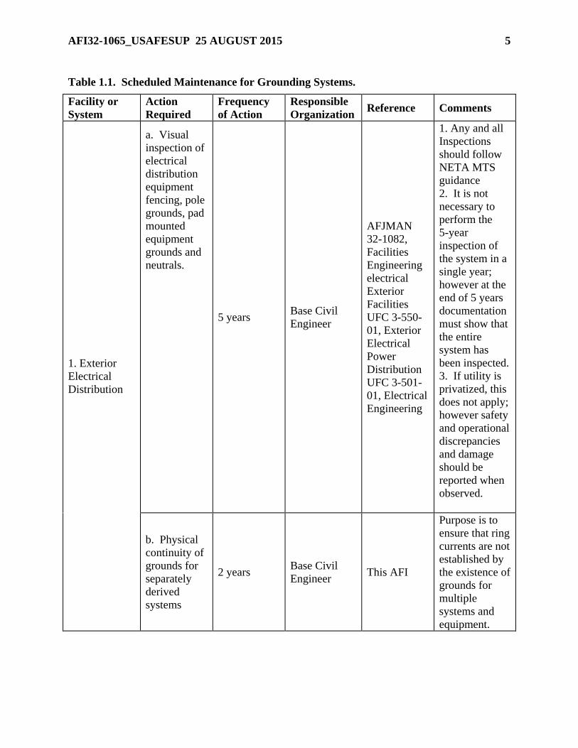
Table 1.1. Scheduled Maintenance for Grounding Systems.
Facility or
System
Action
Required
Frequency
of Action
Responsible
Organization Reference Comments
1. Exterior
Electrical
Distribution
a. Visual
inspection of
electrical
distribution
equipment
fencing, pole
grounds, pad
mounted
equipment
grounds and
neutrals.
5 years Base Civil
Engineer
AFJMAN
32-1082,
Facilities
Engineering
electrical
Exterior
Facilities
UFC 3-550-
01, Exterior
Electrical
Power
Distribution
UFC 3-501-
01, Electrical
Engineering
1. Any and all
Inspections
should follow
NETA MTS
guidance
2. It is not
necessary to
perform the
5-year
inspection of
the system in a
single year;
however at the
end of 5 years
documentation
must show that
the entire
system has
been inspected.
3. If utility is
privatized, this
does not apply;
however safety
and operational
discrepancies
and damage
should be
reported when
observed.
b. Physical
continuity of
grounds for
separately
derived
systems
2 years Base Civil
Engineer This AFI
Purpose is to
ensure that ring
currents are not
established by
the existence of
grounds for
multiple
systems and
equipment.

6 AFI32-1065_USAFESUP 25 AUGUST 2015
2. Electrical
Substation 1
(if base owned
or
totally/partiall
y maintained
by the base)
a. Continuity
check across
gate opening
(1 ohm or
less)
5 years Base Civil
Engineer
AFJMAN
32-1082;
NETA MTS
b. Ground
resistance
measurement
of entrance
gate (5 ohms
or less)
3. Exterior
Lightning
Arresters
and/or surge
suppressive
devices on
Primary
Distribution
Lines (even if
privately
owned).
Visual 5 years Base Civil
Engineer
AFJMAN
32-1082
Purpose is to
ensure
reliability to
the AF
mission.
Discrepancies
should be
reported, in
writing, to the
owner if other
than AF.
4. General
a. Facility
Service
Entrance -
visual
inspection
When
electrical
work is
performed at
facility
Base Civil
Engineer
NFPA 70
(NEC), Art
250,
NFPA 70
(NEC)B,
UFC 3-575-
01, Lightning
and Static
Electricity
Protection
Systems
Tag or mark in
a conspicuous
place, to
indicate visual
inspection date
and initials of
inspector
AFI32-1065_USAFESUP 25 AUGUST 2015 7
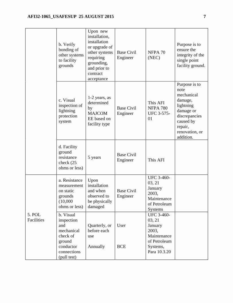
b. Verify
bonding of
other systems
to facility
grounds
Upon new
installation,
installation
or upgrade of
other systems
requiring
grounding,
and prior to
contract
acceptance
Base Civil
Engineer
NFPA 70
(NEC)
Purpose is to
ensure the
integrity of the
single point
facility ground.
c. Visual
inspection of
lightning
protection
system
1-2 years, as
determined
by
MAJCOM
EE based on
facility type
Base Civil
Engineer
This AFI
NFPA 780
UFC 3-575-
01
Purpose is to
note
mechanical
damage,
lightning
damage or
discrepancies
caused by
repair,
renovation, or
addition.
d. Facility
ground
resistance
check (25
ohms or less)
5 years Base Civil
Engineer
This AFI
5. POL
Facilities
a. Resistance
measurement
on static
grounds
(10,000
ohms or less)
Upon
installation
and when
observed to
be physically
damaged
Base Civil
Engineer
UFC 3-460-
03, 21
January
2003,
Maintenance
of Petroleum
Systems
b. Visual
inspection
and
mechanical
check of
ground
conductor
connections
(pull test)
Quarterly, or
before each
use
Annually
User
BCE
UFC 3-460-
03, 21
January
2003,
Maintenance
of Petroleum
Systems,
Para 10.3.20

8 AFI32-1065_USAFESUP 25 AUGUST 2015
c. Inspection
of connection
to grounding
electrode
Annually BCE
UFC 3-460-
03, 21
January
2003,
Maintenance
of Petroleum
Systems,
Para 10.3.20
d. Facility
Service -
visual
inspection
When
electrical
work is
performed at
facility
BCE
NFPA 70
(NEC), Art
250,
NFPA 70
(NEC)B,
Tag or mark in
a conspicuous
place, to
indicate visual
inspection date
and initials of
inspector
6. Fuels Lab
a. Visual
inspection
and
continuity
validation of
equipment
grounds
Monthly User
AFI 91-203
para
36.5.4.2.2. &
36.5.4.2.3.
b. Visual
inspection of
facility
grounds
Monthly User AFI 91-203
7. Aircraft
Parking Apron
Grounds and
Hangar Floor
Static
Grounds
Resistance
measurement
on static
grounds
(10,000
ohms or less)
When
installed or
repaired
Base Civil
Engineer
UFC 3-575-
01, 1 Jul 12
8. LOX
Storage
Resistance
measurement
on static
ground
(10,000
ohms or less)
When
installed,
physically
damaged, or
repaired
Base Civil
Engineer This AFI
AFI32-1065_USAFESUP 25 AUGUST 2015 9
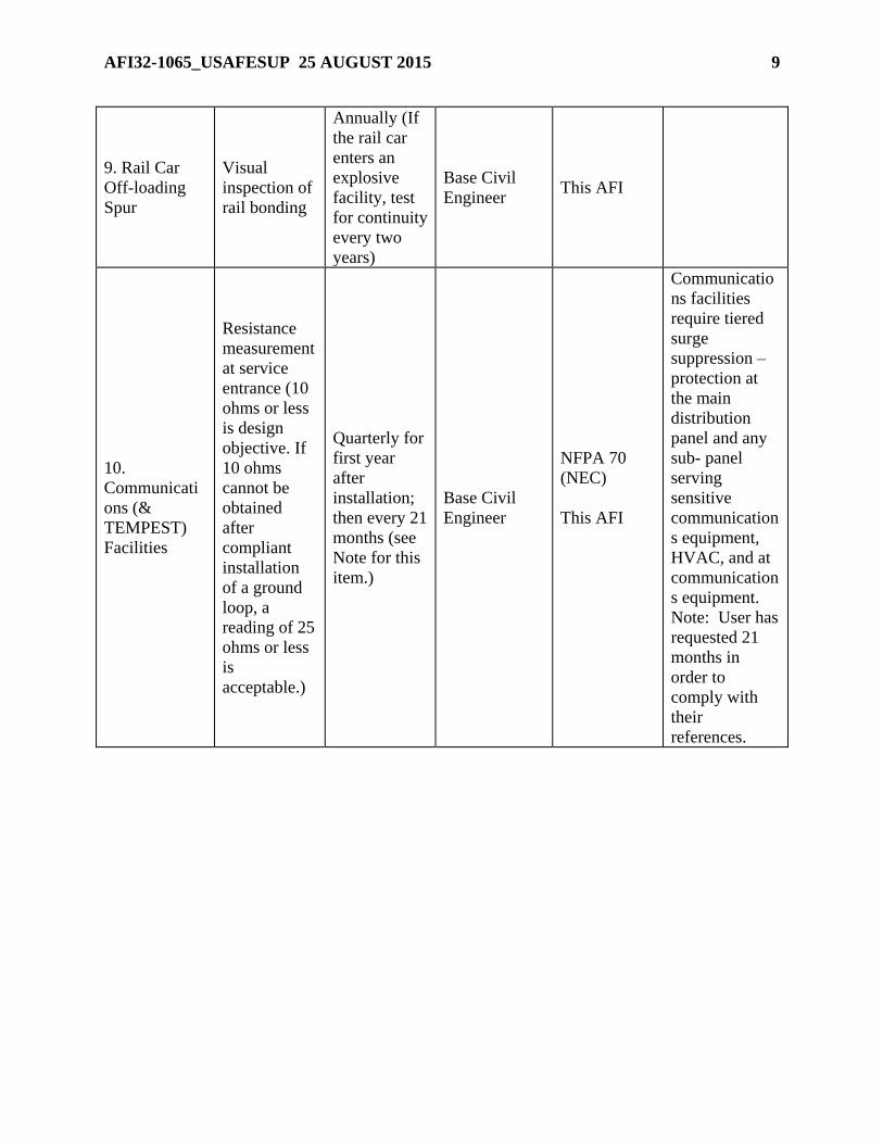
9. Rail Car
Off-loading
Spur
Visual
inspection of
rail bonding
Annually (If
the rail car
enters an
explosive
facility, test
for continuity
every two
years)
Base Civil
Engineer This AFI
10.
Communicati
ons (&
TEMPEST)
Facilities
Resistance
measurement
at service
entrance (10
ohms or less
is design
objective. If
10 ohms
cannot be
obtained
after
compliant
installation
of a ground
loop, a
reading of 25
ohms or less
is
acceptable.)
Quarterly for
first year
after
installation;
then every 21
months (see
Note for this
item.)
Base Civil
Engineer
NFPA 70
(NEC)
This AFI
Communicatio
ns facilities
require tiered
surge
suppression –
protection at
the main
distribution
panel and any
sub- panel
serving
sensitive
communication
s equipment,
HVAC, and at
communication
s equipment.
Note: User has
requested 21
months in
order to
comply with
their
references.

10 AFI32-1065_USAFESUP 25 AUGUST 2015
11.
Communicati
ons
Equipment
Checks
involving in-
house
electronic
equipment
ground
Determined
by user from
T.O. and
equipment
manufacturer
User MIL-HDBK-
419A
Communicatio
ns facilities
require surge
suppression
devices (SPDs)
on both the line
and load sides
of the main
distribution
panel, the line
and load sides
of any panel
serving
sensitive
comm.
equipment, and
at the
communication
s equipment
itself.
Note: For
sensitive
communication
s equipment
inside non-
comm
facilities, SPDs
are required on
the line and
load sides of
the panel
serving
sensitive
communication
s equipment.
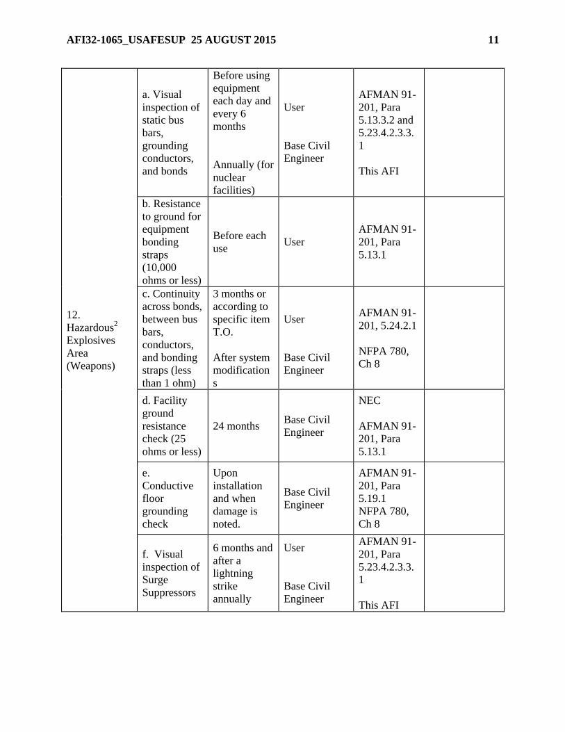
AFI32-1065_USAFESUP 25 AUGUST 2015 11
12.
Hazardous2
Explosives
Area
(Weapons)
a. Visual
inspection of
static bus
bars,
grounding
conductors,
and bonds
Before using
equipment
each day and
every 6
months
Annually (for
nuclear
facilities)
User
Base Civil
Engineer
AFMAN 91-
201, Para
5.13.3.2 and
5.23.4.2.3.3.
1
This AFI
b. Resistance
to ground for
equipment
bonding
straps
(10,000
ohms or less)
Before each
use User
AFMAN 91-
201, Para
5.13.1
c. Continuity
across bonds,
between bus
bars,
conductors,
and bonding
straps (less
than 1 ohm)
3 months or
according to
specific item
T.O.
After system
modification
s
User
Base Civil
Engineer
AFMAN 91-
201, 5.24.2.1
NFPA 780,
Ch 8
d. Facility
ground
resistance
check (25
ohms or less)
24 months Base Civil
Engineer
NEC
AFMAN 91-
201, Para
5.13.1
e.
Conductive
floor
grounding
check
Upon
installation
and when
damage is
noted.
Base Civil
Engineer
AFMAN 91-
201, Para
5.19.1
NFPA 780,
Ch 8
f. Visual
inspection of
Surge
Suppressors
6 months and
after a
lightning
strike
annually
User
Base Civil
Engineer
AFMAN 91-
201, Para
5.23.4.2.3.3.
1
This AFI
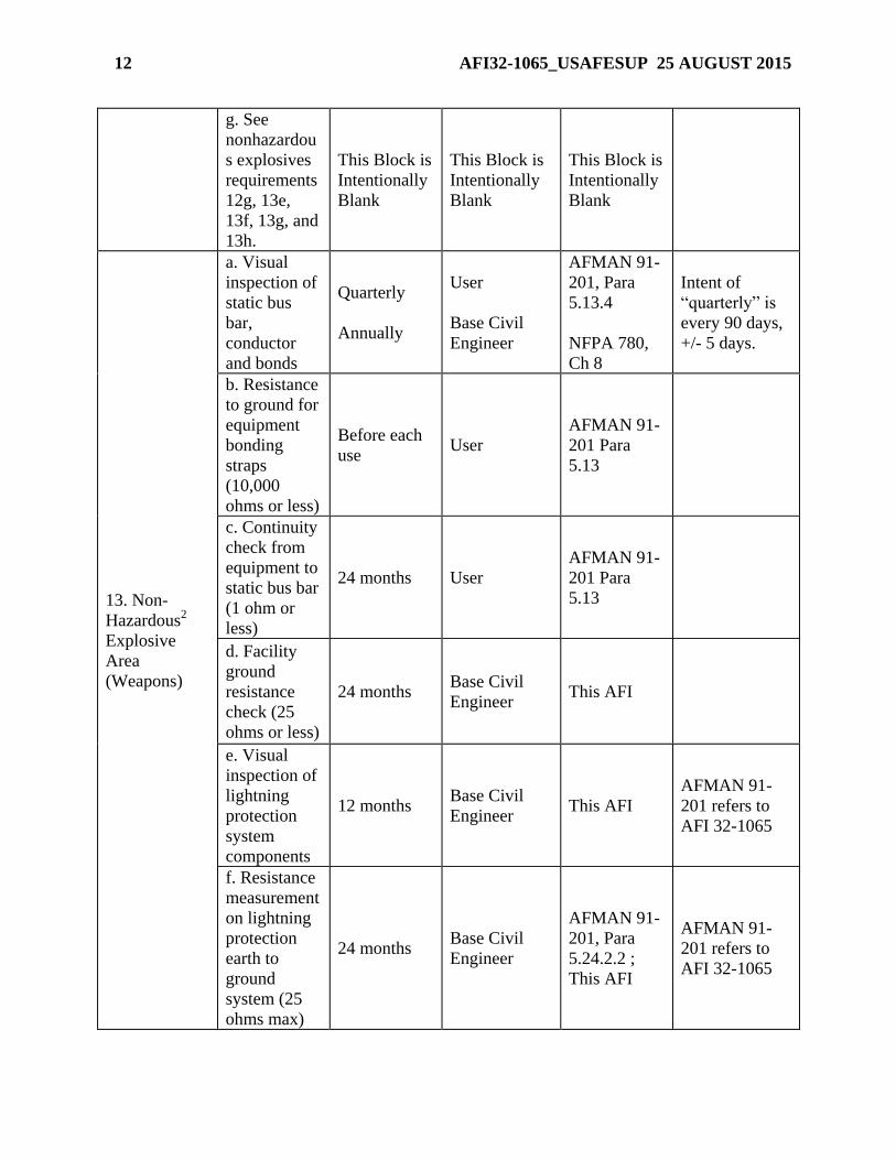
12 AFI32-1065_USAFESUP 25 AUGUST 2015
g. See
nonhazardou
s explosives
requirements
12g, 13e,
13f, 13g, and
13h.
This Block is
Intentionally
Blank
This Block is
Intentionally
Blank
This Block is
Intentionally
Blank
13. Non-
Hazardous2
Explosive
Area
(Weapons)
a. Visual
inspection of
static bus
bar,
conductor
and bonds
Quarterly
Annually
User
Base Civil
Engineer
AFMAN 91-
201, Para
5.13.4
NFPA 780,
Ch 8
Intent of
“quarterly” is
every 90 days,
+/- 5 days.
b. Resistance
to ground for
equipment
bonding
straps
(10,000
ohms or less)
Before each
use User
AFMAN 91-
201 Para
5.13
c. Continuity
check from
equipment to
static bus bar
(1 ohm or
less)
24 months User
AFMAN 91-
201 Para
5.13
d. Facility
ground
resistance
check (25
ohms or less)
24 months Base Civil
Engineer This AFI
e. Visual
inspection of
lightning
protection
system
components
12 months Base Civil
Engineer This AFI
AFMAN 91-
201 refers to
AFI 32-1065
f. Resistance
measurement
on lightning
protection
earth to
ground
system (25
ohms max)
24 months Base Civil
Engineer
AFMAN 91-
201, Para
5.24.2.2 ;
This AFI
AFMAN 91-
201 refers to
AFI 32-1065

AFI32-1065_USAFESUP 25 AUGUST 2015 13
g. Continuity
validation on
air terminals,
bonds, and
conductor
connections
(1 ohm or
less)
24 months Base Civil
Engineer
AFMAN 91-
201; this AFI
h. Static bus
bar
continuity to
ground (1
ohm or less)
24 months Base Civil
Engineer
AFMAN 91-
201; this AFI
14. Protective
Aircraft
Shelter 3 Vault
a. Facility
Single Point
Ground
system
resistance
check
24 months Base Civil
Engineer This AFI
b. Visual
inspection of
grounding
system
12 months Base Civil
Engineer This AFI
c. Continuity
between arch
and ground
(1 ohm or
less)
24 months Base Civil
Engineer This AFI
d. (HAS)
Validate door
hinge
continuity (1
ohm or less )
24 months Base Civil
Engineer This AFI
e. (HAS)
Continuity
between
vault lip
(flange) and
ground
(conduit) (1
ohm or less)
24 months Base Civil
Engineer This AFI

14 AFI32-1065_USAFESUP 25 AUGUST 2015
f. Continuity
of installed
(permanent)
bonds
between
metal masses
and steel
support
When
notified of
damage
Base Civil
Engineer This AFI
g. Visual
inspection of
permanent
bonds
between
metal masses
and steel
support
Annually Base Civil
Engineer This AFI
15. Medical
Facilities 4
a. Resistance
validation
(25 ohms or
less)
5 years Base Civil
Engineer
NFPA 99,
Standard
Health Care
Facilities
b.
Effectiveness
of grounding
system by
voltage and
impedance
measurement
s
Before
acceptance of
new facility
or after
service
entrance
modification
Base Civil
Engineer
AFI 41-203,
Electrical
Safety in
Medical
Treatment
Facilities;
NFPA 99
c.
Verification
of continuity
of receptacle
grounding
circuits
Annual
(semi-annual
for critical
care areas)
Base Civil
Engineer AFI 41-203
16. Airfield
Lighting Vault
Single Point
Facility
Ground
Resistance
check (25
ohms or less)
2 years Base Civil
Engineer This AFI
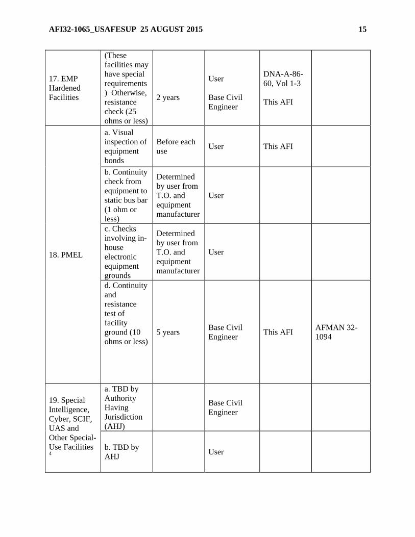
AFI32-1065_USAFESUP 25 AUGUST 2015 15
17. EMP
Hardened
Facilities
(These
facilities may
have special
requirements
) Otherwise,
resistance
check (25
ohms or less)
2 years
User
Base Civil
Engineer
DNA-A-86-
60, Vol 1-3
This AFI
18. PMEL
a. Visual
inspection of
equipment
bonds
Before each
use User This AFI
b. Continuity
check from
equipment to
static bus bar
(1 ohm or
less)
Determined
by user from
T.O. and
equipment
manufacturer
User
c. Checks
involving in-
house
electronic
equipment
grounds
Determined
by user from
T.O. and
equipment
manufacturer
User
d. Continuity
and
resistance
test of
facility
ground (10
ohms or less)
5 years Base Civil
Engineer This AFI
AFMAN 32-
1094
19. Special
Intelligence,
Cyber, SCIF,
UAS and
Other Special-
Use Facilities 4
a. TBD by
Authority
Having
Jurisdiction
(AHJ)
Base Civil
Engineer
b. TBD by
AHJ User
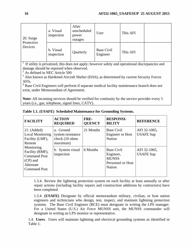
16 AFI32-1065_USAFESUP 25 AUGUST 2015
20. Surge
Protective
Devices
a. Visual
inspection
After
unscheduled
power
outages
User This AFI
b. Visual
inspection Quarterly
Base Civil
Engineer This AFI
1 If utility is privatized, this does not apply; however safety and operational discrepancies and
damage should be reported when observed. 2 As defined in NEC Article 500
3 Also known as Hardened Aircraft Shelter (HAS), as determined by current Security Forces
AFIs. 4 Base Civil Engineers will perform if separate medical facility maintenance branch does not
exist, under Memorandum of Agreement.
Note: All incoming services should be verified for continuity by the service provider every 5
years (i.e., gas, telephone, signal lines, CATV).
Table 1.1. (USAFE) Scheduled Maintenance for Grounding Systems.
FACILITY ACTION
REQUIRED
FRE-
QUENCY
RESPONSI-
BILITY REFERENCE
21. (Added)
Local Monitoring
Facility (LMF),
Remote
Monitoring
Facility (RMF),
Command Post
(CP) and
Alternate
Command Post
a. Ground
system resistance
check (10 ohms
maximum)
21 Months Base Civil
Engineer or Host
Nation
AFI 32-1065,
USAFE Sup
b. System visual
inspection
6 Months Base Civil
Engineer,
MUNSS
Personnel or Host
Nation
AFI 32-1065,
USAFE Sup
1.3.4. Review the lightning protection system on each facility at least annually or after
repair actions (including facility repairs and construction additions by contractors) have
been completed.
1.3.4. (USAFE) Designate by official memorandum military, civilian, or host nation
engineers and technicians who design, test, inspect, and maintain lightning protection
systems. The Base Civil Engineer (BCE) must designate in writing the LPS manager.
For a United States (U.S.) Air Force MUNSS unit, the MUNSS commander will
designate in writing an LPS monitor or representative.
1.4. Users. Users will maintain lightning and electrical grounding systems as identified in
Table 1.

AFI32-1065_USAFESUP 25 AUGUST 2015 17
1.5. (Added-USAFE) MUNSS Responsibilities. The MUNSS LPS Monitor’s primary role
in the LPS program will be to serve as the liaison between the MUNSS commander and host
nation personnel responsible for maintaining LPS. The MUNSS LPS Monitor
responsibilities are as follows:
1.5.1. (Added-USAFE) Maintain a complete listing of MUNSS Weapon Storage and
Security System (WS3) related facilities.
1.5.2. (Added-USAFE) Ensure all WS3 related facilities have installed LPS with
certification by a host nation electrical engineer that the LPS conforms to host nation
standards.
1.5.3. (Added-USAFE) Certification of conformance shall be a memo from the host
nation to the MUNSS commander indicating installed LPS on all WS3 related facilities
complies to host nation standards of design, installation, inspection, and maintenance as
outlined in ACE Directive 80-6.
1.5.4. (Added-USAFE) Ensure testing of LPS installed on WS3 related facilities meets
the frequency and required ohmic values of AFI 32-1065, Table 1., and paragraph 1.1.3.1
of this supplement as a minimum.
1.5.5. (Added-USAFE) Perform 6-month visual inspections of installed LPS in
accordance with AFI 32-1065, paragraphs 9.1. through 9.9., including verifying
operational condition of installed surge suppressors. Forward any discrepancies found to
host nation LPS manager.
1.5.6. (Added-USAFE) Maintain copies of the past six test cycles, and develop a trend
analysis from the test results.
1.5.7. (Added-USAFE) Ensure surge protection is installed on all equipment associated
with the MUNSS WS3 mission and be familiar with procedures and/or actions to verify
surge protectors are operational.
1.5.8. (Added-USAFE) Ensure host nation provides detailed LPS testing procedures
and criteria to MUNSS LPS monitor. LPS testing procedures and criteria shall include,
as a minimum, a checklist for visual and ohmic inspection items, instrumentation setup
procedures, building testing procedures, and certification that testing procedures and
criteria meet host nation standards.
1.5.9. (Added-USAFE) All MUNSS using host nation LPS standards must have a Joint
Operating Instruction (JOI) signed by the MUNSS Commander and Host Nation
Installation Commander. The JOI at a minimum will contain the following information:
1.5.10. (Added-USAFE) That the LPS are maintained under host nation’s standards or
in accordance with AFI 32-1065, paragraph 14.1.
1.5.10.1. (Added-USAFE) Host Nation Responsibilities.
1.5.10.2. (Added-USAFE) MUNSS Responsibilities.
1.5.10.3. (Added-USAFE) Testing Procedures.
1.5.10.4. (Added-USAFE) Testing Frequencies.

18 AFI32-1065_USAFESUP 25 AUGUST 2015
1.6. (Added-USAFE) Responsibilities. The BCE responsibility identified in Table 1 shall
be extended to include persons appointed at locations where base civil engineering is not
provided. These persons shall receive training by methods approved by the Operations
Branch - Civil Engineer commands electrical engineer or be trained by personnel from the
main operating base civil engineering. All LPS managers or their designated alternates are
encouraged to attend USAFE training seminars.
2. Codes and Specifications. Follow applicable codes and specifications in Attachment 1
unless modified in this instruction, or deviations are justified due to local conditions. (T-0)
3. Required Maintenance. Perform required maintenance at the frequencies specified in Table
1. When possible, plan for and schedule maintenance when facility users will be least affected.
(T-0)
4. Recordkeeping and Review.
4.1. Inspectors and testers must compile and maintain records of their inspections and tests
to include (T-0):
4.1.1. A sketch of the grounding and lightning protection system showing test points, and
where services enter the facility. Sketch should also show the location of the probes
during the ground resistance test. (Separate sketches are suggested for static, earth
ground, and lightning protection systems on large complex facilities.)
4.1.2. Date action was performed.
4.1.3. Inspector's or tester’s name.
4.1.4. General condition of air terminals, conductors, and other components.
4.1.5. General condition of corrosion protection measures.
4.1.6. Security of attachment for conductors and components.
4.1.7. Resistance measurements of the various parts of the ground terminal system.
4.1.8. Variations from the requirements of this instruction.
4.1.9. Discrepancies noted and corrective actions taken.
4.1.10. Dates of repairs.
4.2. Review records for deficiencies; also analyze the data for undesirable trends. If test
values differ substantially from previous or original tests obtained under the same test
procedure and conditions, determine the reason and make necessary repairs. (T-0)
4.3. Keep test and inspection records for a minimum of six inspection cycles. (T-1)
4.3. (USAFE) 1 (Added) Keep test and inspection records for a minimum of six inspection
cycles, and develop a documented trend analysis from the result of only the earth testing
results. Trend analysis at a minimum must report the last six testing cycles.
5. Forms. Suggest the use of Air Force general purpose forms (3100 series) to record tests. Use
the format listed in MIL-HDBK-419A, Grounding, Bonding, and Shielding for Electronic
Equipments and Facilities for communications facilities. Provide copies of completed forms to
the facility user. For munitions facilities maintained by host nation civil engineers, the using
agency must receive a copy of the completed forms. (T-1)

AFI32-1065_USAFESUP 25 AUGUST 2015 19
6. Personnel Qualifications. Workers maintaining, repairing, modifying, and testing grounding
systems must be thoroughly familiar with test equipment operation; lightning protection,
grounding, and bonding theory and practices; referenced codes and standards; and specific
requirements and procedures in this instruction. Attachments 2 through 5 provide information
suitable for use in training and familiarization. (T-0)
7. Developing Procedures. The organization performing inspections and tests must develop
procedures based on the requirements in this instruction. (T-0)
Section B—Grounding Resistance and Continuity Tests and Visual Inspections
8. Testing Requirements. See Attachment 6 for resistance and continuity test requirements for
typical systems. Instruments must be able to measure 10 ohms +10 percent for ground resistance
tests, and 1 ohm +10 percent for continuity testing. Only instruments designed specifically for
earth-ground systems are acceptable for ground resistance testing. Follow the manufacturer’s
instruction manual except as modified herein when using the instruments. Earth ground
resistance should be less than 25 ohms unless specified different in this document. Periodic tests
should be made at approximately the same time each year to minimize confusion resulting from
seasonal changes (see Attachment 2). If the resistance measured during continuity tests is greater
than 1 ohm, check for deficiencies and repair, then retest. When per- forming a continuity test
over very long lengths of conductors (more than 20m with no parallel paths), readings above one
ohm but less than 3 ohms may occur. This is acceptable. The MAJCOM electrical engineer may
modify the test procedures due to local conditions, as long as the intent of the test is still
achieved. (T-0)
9. Visual Inspections of Lightning Protection Systems. Inspect all visible parts of the system.
(T-0) Pulling or tugging on conductors and connections to insure soundness is a necessary part
of these inspections, but be careful not to damage the system in the process. Visual/physical
inspection must determine if (T-0):
9.1. The system is in good repair.
9.2. There are loose connections that might cause high resistance joints.
9.3. Corrosion or vibration has weakened any part of the system.
9.4. Down conductors, roof conductors, and ground terminals are intact.
9.5. Braided bonding wires are excessively frayed (cross sectional area reduced by half).
9.6. Ground wires on lightning protection masts are damaged by lawn mowers or other
equipment.
9.7. Conductors and system components are securely fastened to mounting surfaces.
Relocate connections as necessary to better protect against accidental displacement.
9.8. Additions or alterations to the protected structure require additional protection.
9.9. Surge suppressive (overvoltage) devices appear damaged.
9.10. The system complies with applicable sections of NFPA 780, Standard for the
Installation of Lightning Protection Systems (Attachment 4) (T-0).

20 AFI32-1065_USAFESUP 25 AUGUST 2015
10. Visual Inspection of Facility Grounds. Unless otherwise specified by references in Table
1., conduct visual inspections as follows. Inspect all visible and accessible parts of the system.
Determine if they are in good condition and the installation meets NEC requirements
(Attachment 2) (T-0). Typical items to check:
10.1. The system is in good repair.
10.2. There are no loose connections.
10.3. The system neutral is grounded at the service entrance (this includes the connection to
the grounding electrode).
10.4. Separately derived systems are properly grounded.
10.5. Flashover protection is installed on insulating fittings on underground metallic
pipelines entering the facility.
10.6. Grounding systems within the facility are bonded together at ground level or below.
Section C—Grounding and Lightning Protection Requirements
11. Introduction. This section covers requirements for grounding and lightning protection
systems, including systems installed on or in areas such as explosives buildings, magazines,
operating locations and shelters. Use these requirements when inspecting to determine
compliance and when repairing or modifying systems. See AFMAN 91-201, Explosive Safety
Standards (T-1).
12. Testing and Inspecting Static and Lightning Protection Systems and Grounding:
12.1. Procedures. Use Attachment 4 and Attachment 5 as a guide for establishing proper
maintenance procedures and a check during self-inspections.
12.2. Inspection and Testing. Inspect the static and lightning protection systems and
grounding for buildings and facilities visually and electrically according to Sections A,
Maintenance Policy and B, Grounding Resistance and Continuity Tests and Visual
Inspections, and the special requirements in this section (T-0).
12.3. Records. Keep records of test and inspections for explosives facilities for a minimum
of six inspection cycles (see paragraph 4) (T-0). Figure 1 is an example sketch of a
grounding and lightning protection system with test points.
12.4. (Added-USAFE) USAFE Testing. According to ACE Directive 80-6, Volume 2/US
EUCOM Directive (ED 60-10), Nuclear Surety Management, and ACE Directive 80-6,
Volume 2, Part II/ED 60-12, Nuclear Surety Management for the WS3, as a minimum, test
European weapon storage areas lightning protection systems, and hardened aircraft shelters
with WS3 vaults under United States Air Force (USAF) control, according to U.S. standards
and testing procedures. Use host nation requirements if they meet or exceed U.S.
requirements. This includes LPS and facility grounding testing schedules that are
accomplished more frequently by many host nations.

AFI32-1065_USAFESUP 25 AUGUST 2015 21
12.4.1. (Added-USAFE) Testing Apparatus. Ground and LPS resistance-testing
equipment shall be calibrated according to Technical Order (TO) 33K-1-100-CD-1,
TMDE Calibration Notes Maintenance Data Collection Codes, Cal Measurement
Summaries Calibration Procedure, Calibration Interval and Work Unit Code Reference
Manual, and/or manufacturer’s technical data and operating instructions available to
operators.
Figure 1.1. Example Sketch of Test Points (Typical).
13. Static Protection
13.1. Equipment Grounding. The best methods to eliminate or reduce the hazard from static
electricity are bonding and grounding. Bonding minimizes potential differences between
conductive objects. Grounding minimizes potential differences between objects and the
ground. Inspect and test facilities for compliance with NFPA 77, Static Electricity, which
contains the minimum acceptable static grounding and bonding requirements for Air Force
activities, except as modified herein (T-0).

22 AFI32-1065_USAFESUP 25 AUGUST 2015
13.1.1. Bonding and grounding wires must be large enough to withstand mechanical
damage. Minimum size for existing bonds is AWG No. 8. Make repairs with wires no
smaller than AWG No. 6 copper. Static grounds for portable or movable equipment must
use braided cable for added flexibility. (T-0)
13.1.2. Static grounds must be 10,000 ohms or less, unless otherwise stated. Static
electricity creates extremely small (milliamps) currents, so even this large resistance is
small enough to bleed off static charges. But because the static grounding system must be
connected to the facility grounding system, resistances of less than 25 ohms are common.
(T-0)
13.2. Static Bus Bars. Static bus bars are usually 2- by 1/4-inch copper bars installed on the
interior wall of the facility. Bond static bus bars directly to each lightning protection down
conductor where it crosses the down conductor if separation between the two is within NFPA
780 bonding distance and the bus or down conductor cannot be relocated. They must also be
connected directly to the facility grounding electrode system. See Attachment 6 for testing
requirements. Use static bus bars only for static grounding. Do not connect telephone
grounds, electrical conduit or intrusion systems to this bus. Static bus bars must not be used
as a grounding medium for these systems. As a general rule, do not connect a static bus to
any facility metal body or use this bus to ground structural components of a facility;
however, coincidental connections of the bus bar through its anchoring/mounting system are
acceptable as is the mounting of the static bars on the skin of a metal structure. Portable
grounding straps from equipment to the static grounding bus are not real property. Visual
inspections and continuity checks for these straps are the responsibility of the user. (T-0)
13.3. Belting Requirements. On equipment such as belt-driven compressors and conveyor
belts, if static electricity is a hazard, use non-static-producing belting. Belting must have a
resistance not exceeding 1,000,000 ohms when measured according to IEEE STD 142,
chapter 3. (T-0)
13.4. Conductive Floor Grounds. If the facility requires conductive floors, the resistance of
the floor must be less than 1,000,000 ohms. Additionally, the resistance between the floor
and ground connections must not be less than 25,000 ohms. This requirement protects
personnel from electric shock hazard and allows bleed off of static buildup in people and
operating equipment. See Attachment 6 for testing requirements. The testing and using
agency must keep a record of test results. (T-0)
14. Lightning Protection Systems. AFMAN 91-201 identifies explosives facilities that require
lightning protection systems. Many other structures housing critical or sensitive supplies or
equipment also require protection. The following requirements will be used as a guide for
facilities that require lightning protection. (T-1)
14.1. General. Systems must comply with NFPA 780 and AFM 88-9, Chapter 3, Electrical
Design Lightning and Static Electricity Protection (except as modified herein). (T-0) Early
streamer emission systems or charge dissipation systems are not permitted. Parts and
materials must carry the Underwriters Laboratories (UL) label or equivalent. (T-0)
Otherwise, such components must be approved by the MAJCOM electrical engineer in
charge of lightning protection. (T-2) Facilities in foreign countries may use host nation
codes and standards if they offer equivalent protection, as determined by the MAJCOM
electrical engineer with concurrence from HQ AFCEC/COSM and approval of the DoD

AFI32-1065_USAFESUP 25 AUGUST 2015 23
Explosive Safety Board (DDESB). (T-0) Otherwise, the Status of Forces Agreement (SOFA)
must permit their use. Where the SOFA requires compliance with host nation codes, translate
those required codes into English, make them available to all appropriate personnel, and
perform necessary training. Maintain all installed systems according to this instruction. If not
required, remove the LPS system with coordination through the using agency. (T-0)
14.1. (USAFE) Host Nation Codes and Standards. For those facilities in foreign
countries that must use host nation codes and standards, the BCE shall determine if required
LPS systems meet U.S. standards. If this cannot be determined through on-site resources, the
BCE must formally request, via message, USAFE Command Electrical Engineer assistance
to evaluate the LPS systems installed at these locations. The USAFE Command Electrical
Engineer will determine whether the host nation codes and standards offer equivalent
protection, and coordinate with Air Force Civil Engineer Support Agency (AFCESA/CESE)
and the Department of Defense (DoD) Explosive Safety Board (DDESB) according to AFI
32-1065, paragraph 14.1. Formal requests shall become a permanent part of LPS records.
14.1.1. (Added-USAFE) Approval of LPS and Grounding System
Components. Host nation LPS and grounding system parts and components approved
by organizations listed in Attachment 7 of this supplement are recognized by the
USAFE Command Electrical Engineer as equivalent to Underwriters Laboratories (UL)
standards and are considered “approved” as required by paragraph 14.1. of AFI 32-1065
when installed according to requirements and design practices contained in AFI 32-1065
and NFPA 780, Standard for the Installation of Lightning Protection Systems. For parts
and components not approved by UL or an organization listed under Attachment 7 of
this supplement, the organization requesting approval for use must prepare a package and
submit it to the Major Command (MAJCOM) electrical engineer. Packages must include
a list of catalog specification sheets and both host nation and UL standards that apply to
the part. The MAJCOM electrical engineer will maintain a database of approved host
nation parts that are available to LPS managers command wide. Approval and use of
host nation LPS parts and components shall not be construed as approval of host nation
LPS or grounding system design. MUNSS shall not be required to comply with this
paragraph.
14.2. Bonding Requirements. Adequate bonding is more important than grounding. Bonding
ensures all metallic objects are at equal potentials, preventing dangerous flashovers. Inspect
and test facilities for compliance with NFPA 780 and Attachment 3 of this instruction. (T-0)
14.3. Grounding Resistance. Low resistance is desirable but not essential for lightning
protection. For most facilities, resistance to ground should be less than 25 ohms. If this
cannot be achieved where only ground rods are used (no ground loop conductor), install a
ground loop conductor. The resistance to ground of a ground loop system is acceptable even
if greater than 25 ohms. See Attachment 2.
14.4. Lightning Protection For Explosives Facilities. Use the basic practices in Attachment
4, with the following additions:
14.4.1. The system must be designed for a 30.5-meter (100-foot) striking distance. (T-0)
14.4.2. Installation of ground wells (hand holes) at corner ground rods is recommended
to aid access for testing.

24 AFI32-1065_USAFESUP 25 AUGUST 2015
14.4.3. Replace existing bolted connectors on down conductors and roof conductors
needing repair with high compression or exothermic-weld type connectors. Connections
to air terminals are an exception, but they must be tight and in good repair. Bolted
connections to aluminum bodies (such as vents) and to metal bodies for the purpose of
bonding are also acceptable. Brazing to metal bodies is allowed but not recommended
due to the possibility of a cold weld with inadequate strength. (T-0)
14.4.4. Structural elements of a facility may serve as air terminals, down conductors, or
the earth electrode.
14.5. Explosives Facilities with Large Perimeters. New explosives facilities (including
igloos) with a perimeter over 91.4 meters (300 feet) that require lightning protection and do
not use the structural steel as the air terminals must use either a mast system or an overhead
wire system. See Attachment 4 for requirements. Since these systems provide better
protection, and maintenance is easier, consider using this type of protection for other kinds of
facilities. The MAJCOM may waive this requirement (overhead or mast system). (T-2)
14.6. Protective Aircraft Shelters (PAS) (also known as Hardened Aircraft Shelter (HAS)).
PASs with interior steel arches or interconnected rebar (i.e., floor rebar that is connected to
wall rebar) and grounded ventilators of metal at least 4.78 millimeters (0.188 inch) thick do
not need air terminals. Metal ventilators less than 4.78 millimeters (0.188 inch) thick must be
protected by an air terminal. All metal bodies in the PAS must be properly bonded and
grounded. See Attachment 3. An adequate grounding system is also required. (T-0)
14.7. Air Force-approved inspectors, with authority to recommend acceptance of LPSs that
protect explosives facilities and communications facilities, are limited to: (T-1)
14.7.1. Nationally recognized inspection agencies who have a minimum 10 years’
experience in inspection of LPS for explosives facilities on DoD or DoE installations and
who have exhibited accuracy in identification of discrepancies, evidenced by no
modifications having been required to the system during the warranty period (see UFC 3-
575-01).
14.7.2. Air Force personnel who have minimum 6 years’ experience in LPS maintenance
and have taken an advanced lightning protection systems senior inspector course.
14.8. (Added-USAFE) Critical Communication Facilities. Critical communication
facilities are defined as the local monitoring facility (LMF), remote monitoring facility
(RMF), command post (CP) and alternate command post. All other communication facilities
will be classified as essential or general dependant on the organizational mission. The
Communications Squadron commander must identify additional facilities, critical to the
surety mission, in writing to the BCE with approval from the installation base and, or wing
commander.
15. Surge Protection 15. Surge Protection is required IAW NFPA 780.(T-0) Surge protective
devices (SPDs), formerly referred to as TVSS (transient voltage surge suppression), protect
equipment from transient voltages resulting from lightning and switching surges and protect the
upstream distribution system from the rapid switching effects of electronics. SPDs are most
effective when used in the form of tiered protection. Tiered protection means providing
protection at main distribution panels, at secondary or sub-panels and at the equipment point of

AFI32-1065_USAFESUP 25 AUGUST 2015 25
use. For protection of non-real property installed equipment, refer to the equipment
manufacturers’ requirements for surge protection.
15.1. Minimum Requirements for Surge Protective Devices for weapons storage areas
(WSAs), munitions storage areas (MSAs) and communications facilities are:
15.1.1. Standard, published, minimum 15-year unlimited replacement warranty on
product (SPD). The entire unit shall be replaced upon detection of the failure of any
mode. (T-1)
15.1.2. All mode (10 modes), directly connected protection elements (l-n, l-g, l-l, n-g)
(T-1)
15.1.3. All steel enclosure, with UL-approved fasteners. (T-1)
15.1.4. Internal over-current fusing on each phase for self-protection from failed
component(s), and an internal disconnect for each phase. (T-1)
15.1.5. Individual component level thermal fusing(T-1)
15.1.6. Bi-polar protection (T-1)
15.1.7. The SPD shall contain continuous, self-monitoring devices with indicator lamps
for each mode. These may be located inside enclosed areas such as mechanical rooms if
an indicator lamp is provided in a visible area. It would be preferable for the indicator
lamp to be installed in a location that can be seen from a vehicle, allowing maintenance
personnel to drive large areas and quickly identify devices which have operated.
Indicator lamps that can be seen in this way will also allow maintenance personnel to
assess whether a group of SPDs in a single area have operated. (T-1)
15.1.8. Cable connection between a bus and SPD shall be minimum No. 10 AWG for
installation at main distribution panels and sub-panels. (T-1)
15.2. Igloos or Earth Covered Magazines (ECMs): up to 60A service
15.2.1. Visible indicators of SPD operation on exterior of facilities. Drive-by visual
inspections may be an effective means of inspecting SPDs.
15.2.2. 60kA/mode to allow the following:
15.2.3. 180kA/phase peak service surge current
15.2.4. Non-modular. The entire unit shall be replaced upon detection of the failure of
one mode of operation. Ease of installation shall not be traded for possible minimized
protection level. (T-1)
15.3. Maintenance Facilities: 400-600A service (T-1)
15.3.1. Visible indicators of SPD operation on exterior of facilities. Drive-by visual
inspections may be an effective means of inspecting SPDs
15.3.2. 180kA/mode to allow the following:
15.3.3. 240kA/phase peak service surge current
26 AFI32-1065_USAFESUP 25 AUGUST 2015
15.3.4. Non-modular. The entire unit shall be replaced upon detection of the failure of
one mode of operation. Ease of installation shall not be traded for possible minimized
protection level. (T-1)
15.4. Communications Facilities: up to 1800A
15.4.1. Visible indicators of SPD operation on exterior of facilities or audible alarm
15.4.2. 200kA/mode (this will allow the following requirement)
15.4.3. 600kA/phase peak service surge current
15.4.4. Non-modular. The entire unit shall be replaced upon detection of the failure of
one mode of operation. Ease of installation shall not be traded for possible minimized
protection level.
15.5. General Requirements: (T-1)
15.5.1. Nominal discharge current test @ 20kA (UL testing allows 10kA or 20kA, but
testing at 10kA is not allowed for Air Force facilities).
15.5.2. Unit Type (UL 1449.2006, 9/29/09):
15.5.2.1. Type 1 unit in front of service panel
15.5.2.2. Type 1 or 2 unit on load side of service panel (not needed for igloos)
15.6. SPDs shall be provided on proprietary equipment by the communications provider or
the tenant communications agency or group. (T-1)
JUDITH A. FEDDER, Lieutenant General, USAF
DCS/Installations, Logistics & Mission Support
AFI32-1065_USAFESUP 25 AUGUST 2015 27
Attachment 1
GLOSSARY OF REFERENCES AND SUPPORTING INFORMATION
References
(Added-USAFE) ACE Directive 80-6, Volume 2, Part II/ED 60-12, Nuclear Surety
Management for the WS3,current edition
(Added-USAFE) ACE Directive 80-6, Volume 2/ED 60-10, Nuclear Surety Management,
current edition
(Added-USAFE) AFMAN 33-363, Management of Records, 1 March 2008
(Added-USAFE) British Standard (BS) 6651:1999, Code of Practice for Protection of
Structures Against Lightning
(Added-USAFE) BS 7430:1998, Code of Practice for Earthing
(Added-USAFE) BS EN 50164-1:2000, Lightning Protection Components
(Added-USAFE) BS EN 60099-1:1994, IEC 60099-1:1991, Surge Arresters
(Added-USAFE) BS EN 60099-5:1997, Surge Arresters-Selection and Application
Recommendations
(Added-USAFE) Bureau De Normalisation (NBN) C 18-100, Code of Practice: Lightning
Protective Systems
(Added-USAFE) CEI 81-1, Protezione di Strutture Contro i Fulmini
(Added-USAFE) CEI 81-4, Valutazione del Rischio Dovuto al Fulmini
(Added-USAFE) CEI 81-5, Componenti per la Protezione Contro i Fulmini
Code of Federal Regulations
7 CFR 1724.50 – Compliance with National Electrical Safety Code
14 CFR 420.71 – Lightning Protection
29 CFR 1910 – Electrical Standards – Final Rule
30 CFR 56.12069 – Lightning Protection for Telephone Wires and Ungrounded Conductors
(Added-USAFE) DD ENV 61024-1:1997, Protection of Structures Against Lightning
(Added-USAFE) DIN EN 50164-1 (VDE 0185 Teil 201) Anforderungen für Verbindungsteile
(Added-USAFE) DIN EN 50164-11 (VDE 0675 Teil 6-11) Überspannungs-Schutzgeräte für
den Einsatz in Niederspannungsanlagen
(Added-USAFE) DIN EN 50164-2 (VDE 0185 Teil 202) Anforderungen an Leitungen und
Erder
(Added-USAFE) DIN EN 61643-21 (VDE 0845 Teil 3-1) Überspannungs-Schutzgeräte für den
Einsatz in Telekommunikations- und Signalverarbeitenden Netzwerken
(Added-USAFE) DIN Normen über Blitzschutzbauteile

28 AFI32-1065_USAFESUP 25 AUGUST 2015
(Added-USAFE) EN 50164-1, Lightning Protection Components
(Added-USAFE) ENV 61024, Protection of Structures Against Lightning
GAO Publications
GAO-005-682R, Federal Real Property: Lightning Protection Systems for Federal Buildings
DoD Publications
DoD 6055.09M, DoD Ammunition and Explosives Safety
D0D Explosives Safety Board Technical Paper 22, Lightning Protection for Explosives Facilities
(Added-USAFE) International Electro-technical Commission (CEI) IEC 62 305, Protection
against lightning VDE-Schriftenreihe 44, Blitzschutzanlagen–Erläuterungen zu DIN57185/VDE
0185
MIL-HDBK-419A, Grounding, Bonding, and Shielding for Electronic Equipments and Facilities
Federal Information Processing Standards (FIP) Pub 94, Guidelines on Electrical Power for ADP
Installations. (Available from National Technical Information Center, US Department of
Commerce, Spring- field VA 22161.)
MIL-STD188-124, Grounding Bonding and Shielding for Common Long Haul/Tactical
Communications Systems, (1992)
Air Force Publications
AFI 32-1063, Electrical Power Systems
(Added-USAFE) AFI 33-360, Publications and Forms Management, 16 May 2006 and the
USAFE Supplement, 16 December 2007
AFI 91-203, Air Force Consolidated Occupational Safety Instruction
AFI 41-203, Electrical Safety in Medical Treatment Facilities
AFMAN 91-201, Explosive Safety Standards
AFJMAN 32-1082, Facilities Engineering, Electrical Exterior Facilities
AFM 85-16, Maintenance of Petroleum Systems
AFM 88-9, Chapter 3, Electrical Design Lightning and Static Electricity Protection
(Added-USAFE) NBN C 18-300, Code of Practice for the Protection of Electronic and Electric
Installations
(Added-USAFE) Netherlands Nornalisatie Institute (NEN) 1014:1992/C2:2000NL,
Bliksembeveiliging
Other
ANSI C2, National Electrical Safety Code (IEEE). (Copies available from The Institute of
Electrical and Electronics Engineers, 345 East 47th Street, New York NY 10017.)
DNA-A-86-60, V1-3, DNA EMP Engineering Handbook for Ground-Based Facilities

AFI32-1065_USAFESUP 25 AUGUST 2015 29
IEEE STD 142, IEEE Recommended Practice for Grounding for Industrial and Commercial
Power Systems (Green Book) 1
IEEE STD 446, Recommended Practice for Emergency and Standby Power (Orange Book) 1
NFPA 70, The National Electrical Code2
NFPA 77, Static Electricity2
NFPA 99, Standard Health Care Facilities2
NFPA 780, Standard for the Installation of Lightning Protection Systems2
Cold Regions Research and Engineering Laboratory (U.S.), Electrical Grounding in Cold
Regions3
NETA MTS, Standard for Maintenance Testing Specifications for Electrical Power Equipment
and Systems
Additional References
IEEE STD 81, IEEE Guide for Measuring Earth Resistivity, Ground Impedance, and Earth
Surface Potentials of a ground System1
IEEE STD 1100, IEEE Recommended Practice for Powering and Grounding Sensitive
Electronic Equipment (Emerald Book) 1
Notes:
1Available from The Institute of Electrical and Electronic Engineers, 345 East 47th Street, New
York NY 10017.
2Available from National Fire Protection Association, 1 Batterymarch Park, Quincy MA
022699990.
3Available electronically at: http://acwc.sdp.sirsi.net/client/search/asset/1012700
(Added-USAFE) T.O. 33K-1-100-CD-1, TMDE Calibration Notes Maintenance Data
Collection Codes, Cal Measurement Summaries Calibration Procedure, Calibration Interval and
Work Unit Code Reference Manual, 29 November 2006
(Added-USAFE) UFC 3-460-03, Operation and Maintenance: Maintenance of Petroleum, 21
January 2003
Abbreviations and Acronyms
(Added-USAFE) U.S.—United States
(Added-USAFE) ACE—Allied Command Europe
AHJ—Authority Having Jurisdiction
ANG—Air National Guard
ANSI—American National Standards Institute
AWG—American wire gauge
BBF—basic bonding formula
30 AFI32-1065_USAFESUP 25 AUGUST 2015
BCE—Base Civil Engineer
(USAFE) BCE—Base Civil Engineer
(Added-USAFE) BS—British Standard
(Added-USAFE) CE—European Conformity
(Added-USAFE) CEI—International Electro-technical Commission
DDESB—Department of Defense Explosive Safety Board
DoD STD—Department of Defense Standard
(Added-USAFE) ED—United States European Command Directive
EMP—electromagnetic pulse
(Added-USAFE) EN—European Norm
FIPS—Federal Information Processing Standard
IAW—In Accordance With
IEEE—Institute of Electrical and Electronics Engineers
IG—isolated ground
(Added-USAFE) JOI—Joint Operating Instruction
(Added-USAFE) LMF—Local Monitoring Facility
LOX—liquid oxygen
(Added-USAFE) LPS—Lightning Protection System
MAJCOM—major command
MIL HDBK—Military Handbook
MOV—metal oxide varistor
(Added-USAFE) MUNSS—Munitions Support Squadron
NBN—no bonding needed
(USAFE) NBN—Bureau De Normalisation
NEC—National Electrical Code
(Added-USAFE) NEN—Netherlands Normalisatie Institute
NFPA—National Fire Protection Association
PAS—Protective Aircraft Shelter (also known as Hardened Aircraft Shelter (HAS))
(USAFE) PAS—-Protective aircraft shelter
POL—petroleum, oils, lubricants
PMEL—Precision Measurement Equipment Laboratory
(Added-USAFE) RMF—Remote Monitoring Facility

AFI32-1065_USAFESUP 25 AUGUST 2015 31
SDS—separately derived system
SOFA—Status of Forces Agreement
T.O.—Technical Order
(Added-USAFE) UL—Underwriters Laboratories
(Added-USAFE) USAFE—United States Air Forces in Europe
WS3—Weapon Storage and Security System
Terms
Air Terminal—The component of the lightning protection system intended to intercept
lightning flashes, placed on or above a building, structure, or tower. A building’s grounded
structural elements may be used as an air terminal. Sometimes air terminals are referred to as
lightning rods.
Bonding—An electrical connection between an electrically conductive object and a component
of a lightning protection system that is intended to significantly reduce potential differences
created by lightning currents.
Conductor, Bonding—A conductor used for equalization potential between metal bodies and
the lightning protection subsystem.
Catenary System—A lightning protection system consisting of one or more overhead wires.
Each overhead wire forms a catenary between masts, and serves the function of both a strike
termination device and a main conductor.
Conductor, Main—A conductor intended to carry lightning currents from the point of
interception to ground terminals.
Copper Clad Steel—Steel with a coating of copper bonded on it.
Down Conductor, Lightning—The conductor connecting the roof conductors or overhead
ground wire to the earth ground subsystem.
Ground Loop—A conductor, buried 3 to 8 feet from a structure, encircling the structure
interconnecting ground electrodes. The conductor may be connected to buried copper or steel
plates or ground rods.
These are installed to establish a low resistance contact with earth. (Also referred to as
counterpoise, loop conductor, or closed loop systems.)
Facility Ground System—The electrically interconnected system of conductors and conductive
elements that provides multiple current paths to earth. The facility ground system can include
the earth electrode subsystem, lightning protection subsystem, signal reference protection
subsystem, fault protection subsystem, static ground subsystem, as well as the building structure,
equipment racks, cabinets, conduit, junction boxes, raceways, duct work, pipes, and other
normally non-current-carrying metal elements.
Ground—The electrical connection to earth primarily through an earth electrode subsystem.
This connection is extended throughout the facility by the facility ground system.

32 AFI32-1065_USAFESUP 25 AUGUST 2015
Ground Terminal—The portion of a lightning protection system such as a ground rod, ground
plate, or ground conductor that is installed for the purpose of providing electrical contact with the
earth.
Inherent Bond—Where metal bodies located in a steel-framed structure are electrically bonded
to the structure through the construction.
Integral System—A system which uses air terminals mounted directly on the structure to be
protected.
Lightning Protection System—A complete system consisting of components (such as air
terminals, interconnecting conductors, ground terminals, surge suppression devices, and other
connectors or fittings) and subsystems required to assure a lightning discharge will be safely
conducted to earth.
Mast System—A lightning protection system using masts that are remote from the structure to
provide the primary protection from a lightning strike.
Overhead Wire System—System using conductors routed over the facility, at a specified
height, designed to provide the required zone of protection. Also known as overhead shield wire
system and catenary system.
Side Flash—Electrical arcing between metal objects caused by difference of potential from a
lightning discharge.
Strike Termination Device—A component of a lightning protection system intended to
intercept lightning flashes and connect these flashes to a path to ground. Strike termination
devices include air terminals, masts, permanent parts of structures, and overhead wires in
catenary systems.
TEMPEST—Unclassified name for investigation/study of compromising emanation.
Zone of Protection—Space below and adjacent to a lightning protection subsystem that is likely
to avoid direct lightning discharges.

AFI32-1065_USAFESUP 25 AUGUST 2015 33
Attachment 2
BASIC REQUIREMENTS FOR GROUNDING SYSTEMS (T-0)
A2.1. Types of Grounds. There are five basic types of grounding systems which must be
inspected if present in a facility: static grounds, equipment grounds, electrical system grounds,
lightning grounds, and signal reference grounds.
A2.1.1. Static Grounds. A static ground is a connection between a piece of equipment and
earth to drain off static electricity charges before they reach a sparking potential. Typically,
static grounding involves connecting large metal objects such as fuel tanks or aircraft to earth
through a ground rod. Static grounds are not part of an electrical power system. But if an
equipment grounding conductor is adequate for power circuits, it is also adequate for static
grounding.
A2.1.2. Equipment Grounds. Equipment grounding involves interconnecting and connecting
to earth all non-current-carrying metal parts of an electrical wiring system and equipment
connected to the system. The purpose of grounding equipment is to ensure personnel safety
by reducing any charge in an equipment item to near zero volts with respect to ground.
Equipment ground must be capable of carrying the maximum ground fault current possible
without causing a fire or explosive hazard, until the circuit protective device clears the fault.
An example is the bare copper wire or green insulated conductor connected to the frames of
electric motors, breaker panels, and outlet boxes. The equipment ground is connected to an
electrical system ground (neutral) only at the electrical service entrance of a building and
should not exceed 25 ohms to ground.
A2.1.3. Electrical System Ground. The purpose of electrical system grounds is to stabilize
voltage to ground and give a low impedance path for fault currents. One wire or point of an
electrical circuit in an electrical system ground is connected to earth. This connection is
usually at the electrical neutral (though not always), and is called the "system ground."
Examples of electrical system grounds are generator or transformer neutral points connected
to earth, and the grounded neutral of an interior wiring system. The resistance of most
electrical system grounds below 600 Vac should not be more than 25 ohms. Medium voltage
systems (1-15kV) frequently are grounded through a resistor (or reactor) and may exceed 25
ohms. This limits ground fault current to a manageable level.
A2.1.4. Lightning Grounds. The purpose of lightning grounds is to safely dissipate lightning
strokes into the earth. They are part of a lightning protection system which usually includes
air terminals (lightning rods), down conductors, arresters, and other connectors or fittings
required for a complete system. The sole purpose of a lightning protection system for a
facility is to protect the building, its occupants, and contents from the thermal, mechanical
and electrical effects of lightning.
A2.1.5. Signal Reference Grounds. The purpose of a signal reference ground is to provide a
low impedance signal reference system for electronic equipment to minimize noise-induced
voltages and thereby reduce equipment malfunctions. Common configurations include planes
and grids. See FIPS Pub 94, Guidelines on Electrical Power for ADP Installations, for
details.

34 AFI32-1065_USAFESUP 25 AUGUST 2015
A2.1.6. Subsystem Grounds. Each of the grounding systems described above may be a
subsystem of a total facility grounding system. All grounds (and subsystems) must be bonded
together according to NFPA 780 and NFPA 70, The National Electrical Code. MIL-HDBK-
419A contains example sketches of grounding subsystem interconnections.
A2.2. NEC Grounding Requirements. Electrical systems and circuit conductors are grounded
to limit voltages during lightning and to facilitate overcurrent device operation in case of a
ground fault. The NEC allows the system neutral to be grounded and limits the location of this
neutral to earth connection to the source side of the service entrance disconnect or at a separately
derived system (NEC, articles 250-23 and 250-26). Since the neutral will carry current under
normal operating conditions, the NEC often refers to it as the grounded conductor. If a building
service is at less than 1000 volts, a neutral conductor (if required by NEC, article 250-5) must be
run to each service entrance from the servicing transformer and bonded to the disconnecting
panel enclosure. In contrast to the neutral, the equipment ground conductor (green insulated or
bare wire) is referred to as the grounding conductor. The grounding conductor is used to ground
metallic enclosures and motor frames, and must be connected to neutral only on the source side
of the service entrance disconnect.
A2.2.1. Facility Ground. The NEC requires a premises wiring system to have a grounding
electrode at each service. This electrode may be of several different types or systems. Each of
the types listed below must be bonded together to form the grounding electrode system.
Where none of the listed electrodes are present, ground rods or ground plates must be used.
Ground rods must be at least 2.44 meters (8 feet) in length (10 feet for lightning protection;
see Attachment 4) and no closer than 1.83 meters (6 feet) from other rods or plates. Ground
rods or plates must not be aluminum. The Air Force also prohibits stainless steel ground rods.
A2.2.1.1. Where a metal underground water pipe (uncoated) is in direct contact with the
earth for 3.05 meters (10 feet) or more, do not bond around insulation flanges installed
for cathodic protection. If the underground water pipe is the only electrode available,
ground rods must supplement it.
A2.2.1.2. The metal frame of a building where the building is effectively grounded.
A2.2.1.3. An electrode encased by at least 51 millimeters (2 inches) of concrete, made of
at least 6.1 meters (20 feet) of one or more steel reinforcing bars, located within and near
the bottom of a concrete foundation or footing in direct contact with the earth. This is
known as a Ufer ground.
A2.2.1.4. A ground ring encircling the building at least 0.76 meters (2.5 feet) deep. The
ground ring must be at least 6.1 meters long and use at least AWG No. 2 copper (1/0
copper for lightning protection ground ring conductor; see Attachment 4).
A2.2.2. Separately Derived Systems (SDS). A separately derived system is a premises
wiring system where power is derived from a generator, transformer, or converter. An SDS
has no direct electrical (metallic) connection, including the neutral, to the supply conductors
originating in another system. The neutral of an SDS must be connected to a nearby
grounding electrode. In order of preference, this grounding electrode may be building steel,
grounded water pipe, or a separate ground rod. The equipment grounding conductor (green
wire) is bonded to the neutral at this point only. A ground rod can be used only when other
AFI32-1065_USAFESUP 25 AUGUST 2015 35
types of grounding electrodes are not available. All grounding electrodes must be connected
to the facility grounding systems.
A2.2.2.1. Dry type transformers (isolation and non-isolation) are common sources of
SDSs in a facility. Usually, they are connected in a delta-wye configuration. SDS
transformers are widely used in sensitive electronic installations (computer power
distribution centers are essentially SDS transformers), since they effectively establish a
local ground at the electronic equipment. This minimizes the impedance to ground as
seen by the load.
A2.2.2.2. Standby or emergency generators are also common sources of separately
derived systems. However, a generator connected to a facility through a transfer switch is
not a separately derived system if the neutral conductor remains connected to the normal
commercial power source neutral after transfer (the neutral is not switched along with the
phase conductors). In this case, the required connection of the neutral to the facility’s
grounding electrode system for both the commercial power source and the generator must
be made only on the supply side of the commercial power service disconnect. Providing
an additional connection between the generator neutral and a grounding electrode at the
generator would be a grounding connection on the load side of the service disconnect and
a violation of the NEC. Refer to IEEE Standard 446, Recommended Practice for
Emergency and Standby Power (The Orange Book), for additional information and
requirements on grounding emergency and standby generators.
A2.3. Grounding Electrodes.
A2.3.1. Connection To Earth. The most practical method of connecting to earth is to bury a
solid body, such as a metal rod, pipe, or sheet, and connect a grounding conductor to it. This
solid body is known as a grounding electrode.
A2.3.2. Methods for Obtaining Better Grounds. Frequently a satisfactorily low electrode
resistance cannot be obtained because of high soil resistivity. Use the following methods if it
is necessary to lower the resistance of the electrode.
A2.3.2.1. Deeper Rod. As a rod is driven more deeply into the soil, it not only has more
surface contact with the earth, but it also begins to reach soil which is more conductive.
The deeper the electrode, the less the effect of surface moisture content and temperature
changes.
A2.3.2.2. Parallel Ground Rods. Rods driven in parallel to each other should have space
between them at least the length of the rods. Multiple rods connected by a conductor have
a greater ability to equalize potential over the installation area.
A2.3.2.3. Soil Replacement. You can significantly lower the resistance of a ground rod
by lowering the resistivity of the soil immediately surrounding it. Use a mixture of 75
percent gypsum, 20 percent bentonite (well driller’s mud), and 5 percent sodium sulfate.
This mixture is available from cathodic protection supply companies. The mixture is
better than chemical salts because it lasts much longer and chemical salts may not be
compatible with environmental requirements.
A2.3.2.4. Concrete Encapsulation. Encapsulating ground rods with concrete increases
their effective diameter. The concrete absorbs water from the soil, increasing the

36 AFI32-1065_USAFESUP 25 AUGUST 2015
conductivity directly around the electrode. When buried in the earth, the resistivity of
concrete is about 3,000 ohm-cm.
A2.3.2.5. Other Methods. Other more elaborate methods include installation of a ground
loop conductor and extensive wire networks.
A2.4. Grounding and Corrosion. Copper grounding has been the standard of the electrical
industry almost from inception. Because it is cathodic to all common construction materials,
corrosion often results when copper is in contact with ferrous structures. Bonding underground
ferrous structures to copper grounding systems can create serious corrosion problems.
A2.4.1. Corrosion of Pipelines. A typical situation exists when a facility’s copper grounding
system is bonded to a coated steel pipeline (such as petroleum, oils, or lubricants (POL) or
natural gas) entering the facility. Outside the facility the pipe is buried in low resistivity soil.
Corrosion current will be high because of the potential between copper and steel, the low
resistance circuit, and concentrated at the voids (holidays) in the pipe coating. One common
solution to this problem is to use galvanized steel rather than copper ground rods. Another is
to install an insulating fitting above the ground in the pipeline where it exits the soil and as it
enters the building. Note that while the aboveground portion of the pipeline is grounded for
safety, the underground portion is already grounded by contact with the soil. The resistance
to earth of a typical coated piping system is usually 1 to 5 ohms.
A2.4.2. Hazardous Voltages. If insulating fittings are installed on a pipeline, take
precautions against lightning flashover at the fittings or a dangerous potential difference
between the pipe sections. Connect a metal oxide varistor (MOV) lightning arrester, zinc
grounding cell, or an electrolytic cell across the insulating device. The clamping voltage
should be 3.14 times the maximum output voltage of the rectifier of the cathodic protection
system.
A2.4.3. Zinc Grounding Cell. A zinc grounding cell is made of two bars of 3.55 by 3.55 by
152.4-centimeter (1.4 by 1.4 by 60-inch) zinc separated by 2.54 centimeter (1-inch) spacers.
Each bar has an insulated AWG No. 6 stranded copper conductor silver-brazed to a 0.64-
centimeter (0.25-inch) diameter steel core rod. The unit comes prepackaged in a bag of low
resistivity backfill (75 percent gypsum, 20 percent bentonite, and 5 percent sodium sulfate).
The nominal resistance of a two anode grounding cell is 0.4 ohms. For lower resistance, a
four cross-connected zinc anode cell with a resistance of 0.2 ohms is available. This
resistance acts as an open circuit to the low dc voltage corrosion current, but like a short to
lightning or 120 Vac commercial current.
A2.4.4. Electrolytic Cell. An electrolytic cell (Kirkcell) consists of multiple pairs of stainless
steel plates immersed in a potassium hydroxide electrolyte solution with an oil film floating
on top to prevent evaporation. The cell acts like an electrochemical switch, blocking low dc
voltages in the cathodic protection range, but instantaneously shunting ac or higher dc
voltages to ground.

AFI32-1065_USAFESUP 25 AUGUST 2015 37
Attachment 3 (T-0)
BASIC BONDING REQUIREMENTS
A3.1. Basic Requirements. The following are basic bonding requirements for lightning
protection. See NFPA 780 for more details. Three different conditions or situations determine the
requirement for a bond.

38 AFI32-1065_USAFESUP 25 AUGUST 2015
Condition 1 Condition 2 Condition 3
Long vertical metal bodies
18.3 meters (60 ft) in ver- tical length

AFI32-1065_USAFESUP 25 AUGUST 2015 39
Condition 2
Grounded metal bodies
a. Structures 12.2 m (40 ft) and less
b. Structures more than 12.2m (40 ft) in height
(1) Within 18.3 m (60 ft) from top of structure
(2) Below 18.3 m (60 ft) from top of structure

40 AFI32-1065_USAFESUP 25 AUGUST 2015
Condition 3
Isolated (nongrounded) metallic bodies

AFI32-1065_USAFESUP 25 AUGUST 2015 41
A3.2. Condition 1. This condition addresses long, vertical metal bodies, grounded and
ungrounded, exceeding 18.3 meters in vertical distance. For steel framed structures these long,
vertical metal bodies must be bonded as near as practical at their extremities to structural steel
members. For reinforced concrete structures where the reinforcement is interconnected and
grounded, these long, vertical metal bodies must be bonded to the lightning protection system
(unless inherently bonded through construction) at their extremities. For other structures
bonding is determined the same as Condition 2.
A3.3. Condition 2. This condition addresses bonding of grounded metal bodies not covered by
Condition 1. Where grounded metal bodies are connected to the lightning protection system at
only one extremity, use the following formula to determine if additional bonding is necessary:
This basic bonding formula (BBF) is used in all Condition 2 subcategories. Only the parameter n
may be defined differently. Km is defined the same in all cases and is equal to 1.0 if the
flashover is through air; or 0.5 if through dense material, such as concrete, brick, or wood.
A3.3.1. Condition 2a. For grounded metal bodies in structures 12.2 meters (40 feet) and less in
height, the following apply.
D = the distance between a grounded body and a down conductor at which a bond becomes
necessary.
h = the greatest vertical distance between the bond being considered and the nearest other
lightning protection system bond (or to ground level if no other bond is present).
n = 1 where only one down conductor is within a 30.5-meter (100-foot) radius of the bond in
question.
n = 1.5 where only two down conductors are within a 30.5-meter radius of the bond in question.
n = 2.25 where three or more down conductors are within a 30.5-meter radius of the bond in
question.
Where any two down conductors are not separated by at least 7.6 meters, they must be
considered as one down conductor. An example of this calculation is shown in Figure A3.1.
The height of the building is 10.7 meters (35 feet). A is a metal pipe grounded at one end, but
close to down conductor.
B is the only down conductor within 30.5 meters of the point in question, so n = 1. Since any
flashover would occur through the wall, Km = 0.5. The BBF is D = [h/6(1)](0.5) =
(9.14/6)(0.5) = (1.52)(0.5) = 0.76 meters (2.5 feet). This means that if pipe A is 0.76 meters or
closer to the down conductor at the point in question (9.14 meters in height), bond it through
the wall to the down conductor.
A3.3.2. Condition 2b(1). For grounded metal bodies in structures more than 12.2 meters (40
feet) in height and where the bond in question is within 18.3 meters (60 feet) from the top of
the structure, the following definitions apply.

42 AFI32-1065_USAFESUP 25 AUGUST 2015
h = the greatest vertical distance between the bond being considered and the nearest other lightning
protection system bond (or to ground level if no other bond is present).
n = 1 where only one down conductor is within a 30.5-meter radius of the bond in question.
Down conductors must be spaced at least 7.6 meters apart.
n = 1.5 where two down conductors are within a 30.5-meter radius of the bond in question.
Down conductors must be spaced at least 7.6 meters apart.
n = 2.25 where three or more down conductors are within 30.5 meters of the bond in question.
Down conductors must be spaced 7.6 meters apart.
Figure A3.2. shows bond fitting Condition 2b(1). The vertical height, h1, is 22.9 meters (75 feet).
In this case, the two down conductors are within 30.5 meters of the bond at D1, and n equals 1.5.
Again, the flashover would be through the wall, so Km = 0.5. The BBF is D1 =
([22.9/(6)(1.5)])0.5 = (22.9/ 9)(0.5) = 1.27 meters (4.17 feet). If pipe A is 1.27 meters or closer to
the down conductor, bond it to the down conductor through the wall.
A3.3.3. Condition 2b(2). For grounded metal bodies where the bond in question is below the
top 18.3 meters of a structure which is greater than 12.2 meters (40 feet) in height, the
following definitions apply.
h = the vertical distance between the bond being considered and the nearest other lightning
protection system bond (or to ground level, if no other bond is present).
n = the total number of down conductors (spaced 7.6 meters apart) in the lightning protection
system.
This type of bond is shown in Figure A3.2. Pipe B comes close to a down conductor at a height
below the top 18.3 meters of the structure. Km would be 0.5 for a flash through the wall and n
would be the total number of down conductors for the system (assume 4). The BBF would be
D2 = ([h2/6(4)])0.5 = 10.7/24(0.5) = 0.22 meters (0.73 feet). The pipe B would have to be
bonded through the wall to the down conductor at this location if it is 0.22 meters or closer to the
conductor. Note that for buildings between 12.2 and 18.3 meters in height, Condition 2b(1)
would apply.

AFI32-1065_USAFESUP 25 AUGUST 2015 43
Figure A3.1. Typical Bonding Conditions in Structures 12.2 Meters (40 Feet) or Less.
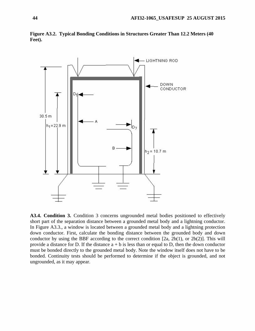
44 AFI32-1065_USAFESUP 25 AUGUST 2015
Figure A3.2. Typical Bonding Conditions in Structures Greater Than 12.2 Meters (40
Feet).
A3.4. Condition 3. Condition 3 concerns ungrounded metal bodies positioned to effectively
short part of the separation distance between a grounded metal body and a lightning conductor.
In Figure A3.3., a window is located between a grounded metal body and a lightning protection
down conductor. First, calculate the bonding distance between the grounded body and down
conductor by using the BBF according to the correct condition [2a, 2b(1), or 2b(2)]. This will
provide a distance for D. If the distance a + b is less than or equal to D, then the down conductor
must be bonded directly to the grounded metal body. Note the window itself does not have to be
bonded. Continuity tests should be performed to determine if the object is grounded, and not
ungrounded, as it may appear.

AFI32-1065_USAFESUP 25 AUGUST 2015 45
Figure A3.3. Typical Bonding Conditions for Ungrounded Metal Bodies.
A3.5. Typical Air Force Situation. Figure A3.4. depicts a situation which typically occurs at
Air Force bases. Objects 1 through 4 are various types of metallic electrical enclosures. These
are required by the NEC to be grounded, and therefore constitute grounded metal bodies as
defined by Condition 2 above. They would have to be bonded to the down conductor if
separation from the down conductor is less than the distance determined by the BBF, Condition
2. Condition 3 would not apply between the door frame and the down conductor with objects 1
through 4 in between, because all are grounded. However, the BBF, Condition 2, has to be
applied between the down conductor and the doorframe. On explosives facilities where such
objects do not need to be bonded, recommend they be marked or labeled "NBN" (No Bonding
Needed) for future reference.
A3.6. Explosives Facility Bonding. The following supplements the NFPA 780 bonding
requirements for explosives facilities defined in chapter 3.
A3.6.1. gives approximate bonding distances as defined by NFPA 780. Note that this chart
does not cover Condition 2b(2). The terms h, Km, and n are defined in paragraph A3.3.1. To
demonstrate the use of the chart, we will use the chart to solve the example in paragraph
A3.3.1.

46 AFI32-1065_USAFESUP 25 AUGUST 2015
Figure A3.4. Bonding for Typical Air Force Structure.
Figure A3.5. Approximate Bonding Distances.
1. Find the height (h) (9.14 m) in the column labeled h.
2. Then select the row adjacent to the 9.14 m where Km is 0.5, since any flashover would occur
through the wall.
3. Since there is only one down conductor, n equals 1. Find the intersection of the row selected
in step 2 and the column labeled 1.0. The value in the cell is 0.76m. Therefore, D is 0.76.

AFI32-1065_USAFESUP 25 AUGUST 2015 47
Also notice that the greatest bonding distance for objects not covered by 2b(2) inside a facility
less than 12.2 meters in height is 1.016 meters (3 feet, 4 inches).
A3.6.2. Steel magazine doors inherently in physical contact with the metallic door frame do not
need a separate bond if this contact measures one ohm or less. Install a bonding strap if this
contact measures greater than one ohm. The frame must be inherently grounded through the
rebar or bonded to a down conductor.
A3.6.3. Objects such as metal desks, large metal trash cans, and ground level floor grates do
not need to be bonded unless required by NFPA 780.
A3.6.4. Fences and railroad tracks within 1.83 meters (6 feet) of a structure’s lightning
protection system must be bonded to the structure grounding system.
A3.6.5. Blast valves must be inherently grounded through the rebar system or with a
separate bonding strap.
A3.6.6. Metal bodies located within a steel framed structure that are inherently bonded to the
structure through construction must be tested when the facility is new and the measurements
recorded and kept with the other required measurements and observations. They do not need
to be tested again unless there is reason to believe the bond has changed; e.g., corrosion or
structural repair.
A3.7. Protective Aircraft Shelters (PASs). In PASs with interior steel arches, all grounded
metal bodies within 0.305 meters (1 foot) of the steel arch must be bonded to the arch. In PASs
without a steel arch, all grounded metal masses within 0.305 meters of a wall must be bonded to
the nearest metallic electrical conduit if not already connected. Only those grounded metal
bodies not inherently bonded (through metallic conduit or equipment grounding conductor) must
be tested for continuity to the ground or conduit system. All metal doors must be grounded. Door
hinges and door tracks are acceptable as a bonding strap if the doorframe or door track is
grounded and there is less than 1 ohm between the door and ground. Additional requirements for
PASs with WS3 vaults:
A3.7.1. Continuity between the steel arch and grounding system may be measured by
ohming between the steel arch and any metallic electrical conduit. Two test points between
different conduits and the arch are sufficient, if the test points are spaced on opposite walls
and the conduit long. This is to ensure electrical continuity through the structural shell. If a
maximum of 1 ohm is not achieved, a bonding strap must be installed.
A3.7.2. When testing continuity between the WS3 vault and steel arch, an acceptable test
location is the vault lip or flange flush with the shelter floor. The vault does not have to be
raised. Where there is no steel arch, test from a metallic electrical conduit on the PAS wall to
the vault lip.

48 AFI32-1065_USAFESUP 25 AUGUST 2015
Attachment 3 (USAFE)
BASIC BONDING REQUIREMENTS
A3.7.3. (USAFE) (Added) WS3 Floor Plates: Continuity between the WS3 Floor Plate and
vault lip shall be less than 1-ohm.
A3.7.4. (Added-USAFE) 4-Part PAS Doors: Continuity between each door section and
PAS arch shall be less than 1-ohm.

AFI32-1065_USAFESUP 25 AUGUST 2015 49
Attachment 4
LIGHTNING PROTECTION SYSTEMS (T-0)
A4.1. Minimum Requirements. Engineers assigned specific responsibilities for lightning
protection should review the lightning protection system on each facility at least annually or after
repair actions have been completed.
A4.1.1. Air terminals must extend at least 0.25 meters (10 inches) above the object to be
protected. NOTE: When replacing air terminals with terminals of a different length, required
spacing around the perimeter must be reconfirmed and the zone of protection verified.
A4.1.2. Each air terminal (except pole- or tower-mounted terminals as exempted in NFPA
780) must be connected to at least two paths to ground. Note that for earth-covered igloos,
these paths may be covered with soil.
A4.1.3. Each building with an integral protection system must have a minimum of two down
conductors, one each at opposite corners (one each on all corners is preferred).
A4.1.4. Down conductors must present the least impedance to ground.
A4.1.5. Down conductors must not have sharp bends or loops. All bends must have a radius
of 203 millimeters (8 inches) or greater and measure not less than 90 degrees from the inside
of the bend. The 203-millimeter radius does not apply to "T" or "Y" splices. These splices,
however, can be used only for the purpose intended.
A4.1.6. If the structure has metallic columns, these columns may serve as down conductors.
Columns must not average over 18.3 meters (60 feet) apart.
A4.1.7. The average distance between down conductors must not exceed 30.5 meters (100
feet).
A4.1.8. Any down conductors subject to mechanical damage or displacement must be
protected with a protective molding or covering for a minimum of 1.83 meters (6 feet) above
grade. If a down conductor runs through a ferrous metal tube or pipe (usually for mechanical
protection), the conductor must be bonded to both ends of the tube.
A4.1.9. Do not paint down conductor connectors unless they are the high-compression or
exothermic (or welded) type. Conductors on roofs must be bare.
A4.1.10. Each down conductor must be connected, at its base, to a grounding electrode.
A4.1.11. Ground rods must be at least 3.05 meters (10 feet) long, made of not less than 0.75
inch diameter pipe or equivalent solid rod made of copper or copper clad steel. Stainless steel
ground rods may not be used. Ground rods must be at least 0.91 meters (3 feet) from the
building walls or footings and must penetrate 3.05 meters into soil. Ground rods with tops at
least 0.31 meters (1 foot) below grade are recommended.
A4.1.12. Interior metal parts of a facility close to a down conductor may need to be bonded
to that down conductor. See NFPA 780 and Attachment 3.
A4.1.13. Bonding materials must be compatible with the metallic mass and down conductor.
A4.1.14. On new facilities, down conductors entering soil with less than 10,000 ohm
centimeters resistivity must be protected against corrosion by a protective covering beginning

50 AFI32-1065_USAFESUP 25 AUGUST 2015
at point 0.91 meters (3 feet) above grade and extending for its entire length below grade (to a
ground rod or ground loop conductor).
A4.1.15. Ground loop conductors must not be less than AWG No. 1/0 copper.
A4.2. Mast and Overhead Wire Systems.
A4.2.1. A mast-type lightning protection system uses masts located remote from the facility.
The mast must be high enough to enclose the facility in the zone of protection according to
NFPA 780. Separate each mast from any part of the facility by at least the bonding distance
specified in Chapter 3 of NFPA 780, but not less than 1.83 meters (6 feet). Refer to Figure
A4.1.
A4.2.2. If a single mast will not protect a facility adequately, install multiple masts or an
overhead wire system. An overhead wire lightning protection system consists of grounded,
elevated, horizontal metallic wires stretched between masts surrounding the facility. Each
wire must be a continuous run of at least AWG No. 6 copper, or equivalent. Suspend each
wire above the protected facility, and connect them to ground rods at each mast or pole.
Interconnect all ground rods with a ground loop conductor. NFPA 780 Table 4.1.1.1.1 and
4.1.1.1.2, specify the minimum separation between the overhead wire and the protected
facility, which must be at least equal to the bonding distance or side flash distance. A
minimum of 1.83 meters (6 feet) is recommended. Supporting masts must be separated by the
side flash distance, but no less than 1.83 meters.
Figure A4.1. Air Terminals on Masts (Typical).
A4.2.3. An air terminal extending above the top of the pole must be securely mounted to the
top of the wooden mast and connected to the grounding system. An overhead ground wire or
a down conductor, extending above or across the top of the pole, may serve as the air
terminal. Each nonmetallic mast must have two down conductors. Metal masts do not require
air terminals and down conductors, but must have two connections to the grounding system.

AFI32-1065_USAFESUP 25 AUGUST 2015 51
Attachment 5
MAINTENANCE GUIDELINES FOR EXPLOSIVES FACILITIES (T-0)
A5.1. Has each facility been inspected to determine the type of protection system installed? Is
the system integrally mounted or separately mounted (mast or overhead wire)?
A5.2. Are personnel from the testing agency familiar with lightning protection systems?
A5.3. Are all test agency personnel who could or do perform the tests or inspections familiar
with this instruction?
A5.4. Are static grounding systems installed as separate subsystems? Are they connected only to
a lightning protection system down conductor (when within side flash), or to a ground loop
conductor? Are contact points free of corrosion, paint, grease, oil, or other agents that prevent
good bonding?
A5.5. Are both the user and testing agencies aware of all facilities that have been identified as
housing or being used to conduct hazardous operations? Are all familiar with any special
test/inspection requirements?
A5.6. Are tests/inspections accomplished at the required frequency?
A5.7. Are tests conducted with the proper test instruments?
A5.8. Are personnel conducting tests familiar with the location of test points and the
relationship between various components of the system being tested?
A5.9. Are visual inspections being performed as required?
A5.10. Are repair actions taken to render the facility safe?
A5.11. After repair actions have been completed, are electrical tests accomplished to ensure the
system integrity?

52 AFI32-1065_USAFESUP 25 AUGUST 2015
Attachment 6
TESTING REQUIREMENTS (T-0)
A6.1. Grounding System Resistance Test. Use the procedure described here or the procedure
recommended by the test instrument manufacturer. Figure A6.1. illustrates auxiliary probe
locations for fall-of-potential ground resistance tests. Where possible, conduct this test at the
corner of the building opposite the electrical service entrance. Exercise caution: underground
metallic piping may influence readings. Position probes as far as possible from the grounding
system under test. You may temporarily disconnect electrical service from other ground
connections; however, make sure you reconnect the ground or a shock hazard will result.
Connect the appropriate lead of a fall-of-potential meter to the ground rod at the test site. Place
the potential reference probe at a distance greater than one-half the diagonal of the building
under test, but not less than 7.6 meters (25 feet). Place the current reference probe 90 degrees
from the potential reference probe (in a direction away from the facility under test) and the
ground rod under test, and at a distance greater than one half of the building diagonal, but not
less than 7.6 meters from the potential reference probe. Note that the distances between probes
are equal. For buildings without a ground loop conductor, perform this test at each ground rod.
Resistance should be less than 25 ohms (10 ohms for communications facilities). Periodic tests
should be made at approximately the same time each year to minimize confusion resulting from
seasonal changes.
Figure A6.1. Auxiliary Probe Locations for Fall-of-Potential Ground Resistance Test.
A6.2. Resistance Test for Above-Ground Petroleum (POL) Tanks. The method described in
paragraph A6.1 is appropriate for medium to small grounding systems. Figure A6.2 illustrates
how to measure resistance to earth of larger, more complex systems such as a large POL tank or
a substation. In areas where the soil resistivity is relatively high, a higher voltage supply may be
necessary. Local cathodic protection technicians can usually furnish the material for the test.

AFI32-1065_USAFESUP 25 AUGUST 2015 53
Make sure the tank is isolated from the utility systems by dielectric flanges. Also be sure the
cathodic protection systems are disconnected.
Figure A6.2. Measuring Resistance to Earth of Large POL Tank.
A6.2.1. Install a temporary ground bed of three or four 1.52-meter (5-foot) ground rods at a
distance equal to five tank diameters. Place a copper-copper sulfate half cell on the opposite
side of the tank. Place it at a distance equal to five tank diameters and along an imaginary
straight line through the center of the tank. Make sure it has good contact with earth.
A6.2.2. Between the temporary ground bed and tank, install a 12-volt common vehicle
battery and a dc ammeter (multimeter with 1-amp scale may be used). Install a high
impedance (10 megohm or greater) dc voltmeter with a 1-volt scale between the half cell and
tank.
A6.2.3. With the battery disconnected, record the voltage reading at the voltmeter.
A6.2.4. Connect the battery and record the current at the ammeter and voltage at the
voltmeter. Read voltage immediately after connecting the battery. Current output must be
sufficient to effect a minimum 0.05 volt potential shift in the half cell reading.
A6.2.5. Calculate resistance of the tank to earth in ohms by dividing the potential change in
volts, DV, by the current in amps; or R = DV/I. For large tanks, typical values would be
0.040 amps of cur- rent and a voltage change of 0.2 V.
A6.3. Resistance Test for Large Objects. This procedure is an alternative to paragraph A6.2
for measuring the resistance to earth of large metallic objects or grids. Be sure to isolate the tank
(or object) from the utility system and turn off any cathodic protection system.
A6.3.1. Install a 2.44-meter (8-foot) ground rod at a distance of five diameters from the tank
(or object being tested). Measure the resistance of this rod to ground using a fall-of-potential
meter. This is the value of Rgr.
A6.3.2. Next, hook up the circuit as shown in Figure A6.3. The resistance of the tank (or
object) to earth is determined by Ro = V/A - Rgr, where V is the reading from the voltmeter
and A is the reading from the ammeter. The ammeter typically reads between 0.1 amp and 2
amps with a 12-volt source.

54 AFI32-1065_USAFESUP 25 AUGUST 2015
A6.3.3. If soil resistivity is very high, increase the voltage until enough amps flow to be
measurable.
Figure A6.3. Alternate Method of Measuring Resistance to Earth of Large Object.
A6.4. Continuity Test/Check for Separately Mounted Lightning Protection System (Mast
and Overhead Shield Wire). Figure A6.4 illustrates a mast and overhead shield wire protection
system. To test the continuity of a mast, connect one lead of an ohmmeter to the top of the pole.
Connect the other lead to the point where the conductor connects to the ground system, at the
ground level. If the resistance is greater than 1 ohm, check for deficiencies and repair. For mast
systems where the masts are metallic of seamless construction of a height to provide adequate
protection, the continuity test can be conducted from the base of the mast. A seamless mast has
all horizontal welds, completed 360 degrees circumferentially. For a system using overhead
shield wire, visually inspect overhead shield wires with binoculars. If the system uses
mechanical connectors, a continuity test must be conducted from the overhead shield wire to the
point where the conductor connects to the ground system, at the ground level (the base of each
mast or guy wire(s) when the guy wire(s) is used as the down conductor). If the resistance is
greater than 1 ohm, check for deficiencies and repair. For systems which use only exothermic
welds or high compression crimps, a visual inspection may used to verify shield wire and down
conductor continuity. The visual inspection may be conducted from ground level using
binoculars.
A6.5. Continuity Test/Check for Integrally Mounted Lightning Protection
Systems. Perform this test by firmly attaching one lead of a ohmmeter to a corner ground rod.
Next, connect the other lead consecutively to each of the air terminals located at the corners of
the building, and the air terminal (or metallic body) with the highest elevation. Repeat the test

AFI32-1065_USAFESUP 25 AUGUST 2015 55
from the ground rod located at the opposite corner of the building. For explosive facilities, test
the continuity to each air terminal. If the continuity of the sys- tem is good, the resistance value
at any given test point should be about the same. Investigate any reading over 3 ohms. NOTE:
Tests can also be performed from ground rod to nearest corner air terminal and from that corner
terminal to the other corner terminals.
A6.6. Testing for Static Bus Bars. Test static bus bars by connecting one lead of a digital
ohmmeter to a ground rod of the facility grounding system. Connect the other lead (in turn) to all
the free ends of the bus bar. Bolted connections between bus bar sections are not considered free
ends. Figure A6.5 shows how a typical static bus bar test is performed. Investigate any reading
more than 3 ohms and correct it. Perform a visual inspection to ensure materials and connections
are in good condition.
Figure A6.4. Mast and Overhead Shield Wire Protection System.
A6.7. Conductive Floor Tests. Before using test instruments, be sure the room is free of
exposed explosives. To determine floor resistance, measure between two electrodes placed 0.91
meters (3 feet) apart anywhere on the floor. Each electrode must weigh 2.27 kilograms (5
pounds) and have a dry, flat circular surface area 63.5 millimeters (2.5 inches) in diameter. The
resistance between an electrode placed anywhere on the floor and a ground connection must not
be less than 25,000 ohms. For more information see IEEE Std 142 and NFPA 99.

56 AFI32-1065_USAFESUP 25 AUGUST 2015
Figure A6.5. Testing Static Bus Bars in Typical Explosives Area.
AFI32-1065_USAFESUP 25 AUGUST 2015 57
Attachment 7 (Added-USAFE)
RECOGNIZED ELECTRICAL GOVERNING BODIES
A7.1. (USAFE) Overview: This attachment lists international electrical governing bodies and
their regulatory and certification standards for the manufacture of parts and components used in
LPS and grounding systems, which are recognized by the USAFE Command Electrical Engineer
as equivalent to UL standards. Parts and components for LPS and grounding systems certified
by the listed organizations are considered “approved” as required by AFI 32-1065, paragraph
14.1., when installed according to requirements and design practices contained in AFI 32-1065
and NFPA 780. Approval and use of host nation LPS parts and components shall not be
construed as approval of host nation LPS or grounding system design.
A7.1.1. (USAFE) International Commissions. International Electrotechnical Commission
(IEC), International Standards Organization (ISO), and the European Committee for
Electrical Standardization (CENELEC).
A7.1.2. (USAFE) Germany Commission. Deutsche Kommission Elektrotechnik
Elektronik Technik, Deutsche Industrie Norm (DIN) and Verband der Elektrotechnik
Electronik Informations Technik e.V. (VDE) Manufacturer’s Conformity Markings:
European Conformity (CE), European Norm (EN), DIN, VDE.
A7.1.2.1. (USAFE) References
CEI IEC 1024-1, Protection of Structures Against Lightning
VDE-Schriftenreihe 44, Blitzschutzanlagen–Erläuterungen zu DIN57185/VDE 0185
DIN Normen über Blitzschutzbauteile
DIN EN 50164-1 (VDE 0185 Teil 201) Anforderungen fuer Verbindungsteile
DIN EN 50164-2 (VDE 0185 Teil 202) Anforderungen an Leitungen und Erder
DIN EN 50164-11 (VDE 0675 Teil 6-11) Überspannungs-Schutzgeräte für den Einsatz in
Niederspannungsanlagen
DIN EN 61643-21 (VDE 0845 Teil 3-1) Überspannungs-Schutzgeräte für den Einsatz in
Telekommunikations- und Signalverarbeitenden Netzwerken
A7.1.3. (USAFE) Italy Commission. Comitato Elettrotecnico Italiano Manufacturer’s
Conformity Markings: CEI, EN.
A7.1.3.1. (USAFE) References
CEI 81-1, Protezione di Strutture Contro i Fulmini
CEI 81-4, Valutazione del Rischio Dovuto al Fulmini
CEI 81-5, Componenti per la Protezione Contro i Fulmini
A7.1.4. (USAFE) United Kingdom (UK) Commission. British Electrotechnical
Committee Manufacturer’s Conformity Markings: CE, BS.
A7.1.4.1. (USAFE) References
BS 6651:1999, Code of Practice for Protection of Structures Against Lightning
BS 7430:1998, Code of Practice for Earthing
BS EN 50164-1:2000, Lightning Protection Components
BS EN 60099-1:1994, IEC 60099-1:1991, Surge Arresters

58 AFI32-1065_USAFESUP 25 AUGUST 2015
BS EN 60099-5:1997, Surge Arresters-Selection and Application Recommendations
DD ENV 61024-1:1997, Protection of Structures Against Lightning
A7.1.5. (USAFE) Netherlands Commission. Netherlands Electrotechnical Committee
(NEC) Manufacturer’s Conformity Markings: CE, European Committee for Standardization
(CEN), NEN.
A7.1.5.1. (USAFE) References
NEN 1014:1992/C2:2000NL, Bliksembeveiliging
A7.1.6. (USAFE) Belgium Commission. Comite Electrotechnique Belge--Manufacturer’s
Conformity Markings: NBN, EN
A7.1.6.1. (USAFE) References
NBN C 18-100, Code of Practice: Lightning Protective Systems
NBN C 18-300, Code of Practice for the Protection of Electronic and Electric Installations
EN 50164-1, Lightning Protection Components
ENV 61024, Protection of Structures Against Lightning