by order of the air force instruction 32-1065...
TRANSCRIPT

BY ORDER OF THE
SECRETARY OF THE AIR FORCE
AIR FORCE INSTRUCTION 32-1065
14 JUNE 2017
Civil Engineering
GROUNDING SYSTEMS
COMPLIANCE WITH THIS PUBLICATION IS MANDATORY
ACCESSIBILITY: Publications and forms are available on the e-publishing website at
www.e-Publishing.af.mil for downloading or ordering.
RELEASABILITY: There are no releasability restrictions on this publication.
OPR: AF/A4C
Supersedes: AFI32-1065, 15 January 2015
Certified by: AF/A4CF
(Mr. Gerald Johnson)
Pages: 71
This instruction implements Air Force Policy Directive (AFPD) 32-10, Installations and
Facilities. It assigns maintenance responsibilities and requirements for electrical grounding
systems on Air Force installations, including systems for equipment grounding, lightning
protection, and static protection. This instruction also implements the maintenance requirements
of DOD 6055.09-M, Volume 2, Ammunition Explosives Safety Standards, Enclosure 4,
“Lightning Protection,” April 2012, for potentially hazardous explosives facilities. This
instruction applies to all personnel, including Air Force Reserve Command (AFRC) units and the
Air National Guard (ANG). This instruction may be supplemented at any level, but all direct
supplements must be routed to the office of primary responsibility (OPR) of this instruction for
coordination prior to certification approval. The authorities to waive wing/unit level
requirements in this publication are identified with a Tier number (“T-0, T-1, T-2, T-3”)
following the compliance statement. See AFI 33-360, Publications and Forms Management, for
a description of the authorities associated with the Tier numbers. Submit requests for waivers
through the chain of command to the appropriate Tier waiver approval authority or to the
publication OPR for non-tiered compliance items. Refer recommended changes and questions
about this publication to the OPR using AF Form 847, Recommendation for Change of
Publication; route AF Forms 847 from the field through the appropriate functional chain of
command. Ensure that all records created as a result of processes prescribed in this publication
are maintained IAW Air Force Manual (AFMAN) 33-363, Management of Records, and
disposed of IAW the Air Force Records Disposition Schedule (RDS) in the Air Force Records
Information Management System (AFRIMS). The use of the name or mark of any specific
manufacturer, commercial product, commodity, or service in this publication does not imply
2 AFI32-1065 14 JUNE 2017
endorsement by the Air Force. This AFI is intended for and applies to trained electrical personnel
only.
SUMMARY OF CHANGES
This instruction has been substantially revised and must be completely reviewed. Major changes
include the addition of Tier wavier authority requirements for added paragraphs, incorporated
Engineering Technical Letters, updated office symbols, updated glossary, updated references,
revision of National Electrical Code (NEC) references to reflect current requirements, revision of
current National Fire Protection Association (NFPA) references to reflect current and upcoming
requirements for new facilities, and clarifications based on questions received from maintenance
personnel. Also included are the incorporation of Engineering Technical Letter (ETL) 11-28:
Mandatory Review and Update of Record Drawings for Nuclear-Capable Weapons and
Munitions Storage and Maintenance Facilities, and Engineering Technical Letter (ETL) 12-9:
Personnel Certification Requirements for Inspection of Lightning Protection Systems (LPS) on
Nuclear Weapons Maintenance, Handling, and Storage Facilities.
Section A— Maintenance Policy 3
1. Responsibilities. ...................................................................................................... 3
Table 1. Scheduled Maintenance for Grounding Systems. ................................................... 5
2. Codes and Specifications. ....................................................................................... 17
3. Required Maintenance. ........................................................................................... 17
4. Recordkeeping and Review for Explosives Facilities. ............................................ 17
5. Forms. ..................................................................................................................... 19
6. Personnel Qualifications. ........................................................................................ 19
7. Developing Procedures. .......................................................................................... 21
Section B— Grounding Resistance and Continuity Tests and Visual Inspections 21
8. Testing Requirements. ............................................................................................ 21
9. Visual Inspections of Lightning Protection Systems. ............................................. 21
10. Visual Inspection of Facility Grounds. ................................................................... 22
Section C— Grounding and Lightning Protection Requirements 22
11. Introduction. ............................................................................................................ 22
12. Testing and Inspecting Static and Lightning Protection Systems and Grounding. . 22
Figure 1. Example Sketch of Test Points (Typical). .............................................................. 23
13. Static Protection. ..................................................................................................... 24

AFI32-1065 14 JUNE 2017 3
Figure 2. Grounding Static Bus Bar on Interior Wall. ........................................................... 25
14. Lightning Protection Systems. ................................................................................ 26
Figure 3. ECM With Center Conductor and Air Terminals. .................................................. 28
Figure 4. ECM Without Center Conductor and Air Terminals. ............................................. 29
15. Surge Protection. ..................................................................................................... 30
Attachment 1— GLOSSARY OF REFERENCES AND SUPPORTING INFORMATION 33
Attachment 2— BASIC REQUIREMENTS FOR GROUNDING SYSTEMS 39
Attachment 3— BASIC BONDING REQUIREMENTS 46
Attachment 4— LIGHTNING PROTECTION SYSTEMS 56
Attachment 5— MAINTENANCE SELF-CHECK FOR EXPLOSIVES FACILITIES 59
Attachment 6— TESTING REQUIREMENTS 60
Section A—Maintenance Policy
1. Responsibilities.
1.1. The Headquarters, United States Air Force, Deputy Chief of Staff for Logistics,
Engineering and Force protection, Directorate of Civil Engineers (HQ AF/A4C) will
ensure compliance with Statutory Law and will develop, maintain, clarify, approve, and
publish Strategy, Doctrine, Policy, and Air Force Instruction for the Grounding System’s
program. HQ AF/A4C will also develop Management Internal Control Toolset (MICT) Self-
Assessment Communicators as part of the oversight strategy for Grounding Systems.
1.2. Air Force Civil Engineer Center (AFCEC) will:
1.2.1. Establish standards and criteria for design, maintenance, repair, and management
of grounding and bonding systems in accordance with mandatory requirements of UFC 3-
520-01, Interior Electrical Systems; UFC 3-550-01, Exterior Electrical Power
Distribution; UFC 3-575-01, Lightning and Static Electricity Protection Systems; and
UFC 3-580-01, Telecommunications Building Cabling Systems Planning and Design. (T-
0).
1.2.2. Review emerging and evolving technologies and evaluates for applicability to the
Air Force.
1.2.3. Evaluate grounding and bonding training conducted internal to the Air Force,
conducted by the Defense Ammunition Center (DAC), and conducted by the private
sector. (T-1).
1.2.4. Assist direct reporting units (DRU) and Air Force installations with inspecting
grounding and bonding systems and with troubleshooting electrical issues suspected to
stem from grounding and bonding issues and discrepancies. (T-2).

4 AFI32-1065 14 JUNE 2017
1.2.5. Assists Air Force Safety Center (AFSEC) and Inspector General (IG) personnel
with determining the equivalency of grounding and bonding protection systems. (T-1).
1.3. The Base Civil Engineer (BCE) will:
1.3.1. Maintain lightning and grounding systems specifically identified in Table 1
according to the procedures within, or procedures referenced by, this instruction. Wavier
tiers per grounding system provided within table.
1.3.2. Ensure that user organizations identified in Table 1 are aware of their maintenance
responsibilities. (T-2).
1.3.3. Train users to perform their responsibilities to inspect and maintain lightning and
grounding systems as identified in Table 1 when requested. On installations where the
electrical utility system is owned by a private entity, consult with the private/system
owner. (T-2).
1.3.4. Review the lightning protection system record drawings on each facility at least
annually or after repair actions (including facility repairs and construction additions by
contractors) have been completed.
1.3.5. Ensure that, for all functions of the civil engineer squadron that are contracted
(e.g., base operations support [BOS] and contractors supporting government-
owned/contractor-maintained facilities/installations), the responsibilities listed within this
instruction are included in the contract, as applicable.

AFI32-1065 14 JUNE 2017 5
1.4. Users. Users will maintain and inspect lightning and electrical grounding systems as
identified in Table 1.
Table 1. Scheduled Maintenance for Grounding Systems.
Facility or
System
Action
Required
Frequency of
Action
Responsible
Organization Reference Comments
Wavier
Authority
1. Exterior
Electrical
Distribution
a. Visual
inspection of
electrical
distribution
equipment
fencing, pole
grounds,
pad-
mounted
equipment
grounds, and
neutrals.
5 years BCE UFC 3-501-01
UFC 3-550-01
1. Any and all
inspections should
follow NETA MTS
guidance
2. It is not necessary
to perform the 5-
year inspection of
the system in a
single year;
however, at the end
of 5 years,
documentation must
show that the entire
system has been
inspected.
3. If utility is
privatized, this does
not apply; however,
safety and
operational
discrepancies and
damage should be
reported when
observed.
T-2
b. Physical
continuity of
grounds for
separately
derived
systems
2 years BCE This AFI
Ensure ring currents
are not established
by the existence of
grounds for
multiple systems
and equipment.
T-2

6 AFI32-1065 14 JUNE 2017
2. Electrical
substation1
(if base-
owned or
totally/partia
lly
maintained
by the base)
a. Continuity
check across
gate opening
(1 ohm or
less)
5 years BCE NETA MTS
T-0
b. Ground
resistance
measuremen
t of entrance
gate (5 ohms
or less)
T-0
3. Exterior
lightning
arrestors
and/or surge
protective
devices on
primary
distribution
lines (even
if privately
owned).
Visual
3-5 years
Critical
systems 1-3
years
Upon
revisions to a
facility
BCE
Ensure reliability to
the Air Force
mission.
Discrepancies
should be reported,
in writing, to the
owner if other than
Air Force, with cc
to BCE
T-3
4. General
a. Facility
service
entrance -
visual
inspection
When
electrical or
communicati
ons work is
performed at
facility
service
BCE
NFPA 70
(NEC), Art.
250
NFPA 70
(NEC), B
UFC 3-575-01
Tag or mark in a
conspicuous place
to indicate visual
inspection date and
initials of inspector
T-3
b. Verify
bonding of
other
systems to
facility
grounds
Upon new
installation,
installation or
upgrade of
other systems
requiring
grounding,
and prior to
contract
acceptance
BCE NFPA 70
(NEC)
Ensure the integrity
of the single point
facility ground
T-0

AFI32-1065 14 JUNE 2017 7
c. Visual
inspection of
lightning
protection
system and
Surge
protective
devices
(SPDs)
1-2 years, as
determined
by the base
AHJ, based
on facility
type.
BCE
This AFI
NFPA 780
UFC 3-575-01
UFC 3-520-01
Note mechanical
damage, lightning
damage, or
discrepancies
caused by repair,
renovation, or
addition
T-3
d. Facility
ground
resistance
check (per
NEC Article
250, 25
ohms or less
at service
grounding
electrode)
5 years BCE This AFI T-3
5. POL
facilities
a. Resistance
measuremen
t on static
grounds
(10,000
ohms or
less)
Upon
installation
and when
observed to
be physically
damaged
BCE UFC 3-460-03 T-1
b. Visual
inspection
and
mechanical
check of
ground
conductor
connections
(pull test)
Quarterly and
when
damaged
User
UFC 3-460-
03, para.
10.3.20
Annually BCE T-1

8 AFI32-1065 14 JUNE 2017
c. Inspection
of
connection
to grounding
electrode
Annually for
other than
thermal weld.
If thermal
weld, inspect
upon
installation
and when
damaged.
BCE
UFC 3-460-
03, para.
10.3.20
T-1
d. Facility
service
entrance -
visual
inspection
When
electrical
work is
performed at
facility,
including
destructive
inspection
and any kind
of electrical
testing, by
other than
BCE
BCE
NFPA 70
(NEC), Art.
250
NFPA 70
(NEC), B
Tag or mark in a
conspicuous place
to indicate visual
inspection date and
initials of inspector
T-0
6. Fuels lab
a. Visual
inspection
and
continuity
validation of
equipment
grounds
Monthly User
AFI 91-203,
paras.
36.5.4.2.2 and
36.5.4.2.3
BCE requirements
are covered in Item
4, general facilities.
T-2
b. Visual
inspection of
facility
grounds
Monthly User AFI 91-203
BCE requirements
are covered in Item
4, general facilities.
T-2
7. Aircraft
parking
apron
grounds and
hangar floor
static
grounds
Resistance
measuremen
t on static
grounds
(10,000
ohms or
less)
When
installed or
repaired
BCE UFC 3-575-01 T-1

AFI32-1065 14 JUNE 2017 9
8. LOX
storage
Resistance
measuremen
t on static
ground
(10,000
ohms or
less)
When
installed,
physically
damaged, or
repaired
BCE This AFI T-2
9. Rail car
off-loading
spur
Visual
inspection of
rail bonding
Annually (If
the rail car
enters an
explosive
facility, test
for continuity
every 2
years)
BCE This AFI T-2
10.
Communicat
ions (&
TEMPEST)
Facilities
Ground
resistance
measuremen
t at service
entrance
(Per NEC
Article 250,
10 ohms or
less at the
service
grounding
electrode is
design
objective. If
10 ohms
cannot be
obtained
after
compliant
installation
of a ground
loop,
resistance is
recorded as
is.)
Quarterly for
first year
after
installation;
then every 21
months (see
Note for this
item)
BCE
NFPA 70
(NEC)
This AFI
Communications
facilities require
tiered surge
suppression –
protection at the
main distribution
panel and any sub-
panel serving
sensitive
communication s
equipment, HVAC,
and at
communication s
equipment.
Note: User has
requested 21
months in order to
comply with their
references. User is
responsible for
trend analysis.
T-0

10 AFI32-1065 14 JUNE 2017
11.
Communicat
ions
Equipment
Checks
involving in-
house
electronic
equipment
ground
Determined
by user from
T.O. and
equipment
manufacturer
User MIL-HDBK-
419A
To prevent the
effects of
transients/surges on
the electrical
distribution,
communications
equipment contracts
should include
SPDs on the load
sides of sub-panels.
If surge protective
devices are required
by the equipment
manufacturer, this is
to be purchased and
installed as part of
the project.
T-3
12.
Hazardous2
explosives
area
(weapons)
a. Visual
inspection of
static bus
bars,
grounding
conductors,
and bonds
Before using
equipment
and every 6
months
User
AFMAN 91-
201, para.
5.13.3.2 and
5.23.4.2.3.3.1
This AFI
NFPA 780,
Ch. 8
Explosives area
governed by
DDESB
T-3
Annually for
nuclear
facilities
BCE T-0
b.
Resistance
to ground
for
equipment
bonding
straps
(10,000
ohms or
less)
When
physically
damaged or
when frayed
from use
User
AFMAN 91-
201, para.
5.13.1
T-3
c. Continuity
across
bonds,
When
physically
damaged
User
AFMAN 91-
201, para.
5.24.2.1
T-3

AFI32-1065 14 JUNE 2017 11
between bus
bars,
conductors,
and bonding
straps (less
than 1 ohm)
After system
modification BCE
NFPA 780,
Ch. 8
Explosives area
governed by
DDESB T-0
d. Facility
ground
resistance
check (per
NEC Article
250, 25
ohms or less
at service
grounding
electrode)
When repair
or renovation
is made to the
facility
BCE
NFPA 70
(NEC)
This AFI
Explosives area
governed by
DDESB
T-0 Per
NEC
T-1 for
repair or
renovation
e.
Conductive
floor
grounding
check
Upon
installation
and when
damage is
reported
BCE
AFMAN 91-
201, para
5.19.1
NFPA 780,
Ch. 8
Explosives area
governed by
DDESB
T-1
f. Visual
inspection of
SPDs
6 months and
after a
lightning
strike
User
AFMAN 91-
201, para.
5.23.4.2.3.3.1
This AFI
Visual inspection
may consist only of
checking for an
indicator lamp,
denoting SPD
operation
Explosives area
governed by
DDESB
T-3
Annually BCE T-0
g. See
nonhazardou
s explosives
requirements
13e, 13f,
13g, and 13i
This block is
intentionally
blank
This block is
intentionally
blank
This block is
intentionally
blank
13. Non-
hazardous2
a. Visual
inspection of
Semi-
annually User AFMAN 91-
201, para.
Intent of
“semiannually” is T-3

12 AFI32-1065 14 JUNE 2017
explosives
area
(weapons)
static bus
bar,
conductor,
and bonds Annually BCE
5.13.4
NFPA 780,
Ch. 8
every 180 days, ±10
days
Explosives area
governed by
DDESB
T-0
b.
Resistance
to ground
for
equipment
bonding
straps
(10,000
ohms or
less)
When
physically
damaged or
when frayed
from use
User
AFMAN 91-
201, para.
5.13
Explosives area
governed by
DDESB
T-3
c. Continuity
check from
equipment to
static bus
bar (1 ohm
or less)
When
physically
damaged
User
AFMAN 91-
201, para.
5.13
NFPA 780,
Ch. 8
Explosives area
governed by
DDESB
T-0
d. Facility
ground
resistance
check (Per
NEC Article
250, 25
ohms or less
at facility
grounding
electrode)
24 months BCE
NEC
This AFI
AFMAN 91-
201, para.
5.13.1
NFPA 780
AHJ
Explosives area
governed by
DDESB
T-0
e. Visual
inspection of
lightning
protection
system
components
12 months BCE
NEC
AFMAN 91-
201, para.
5.24.2.2
This AFI
NFPA 780
AHJ
AFMAN 91-201
refers to AFI 32-
1065
Explosives area
governed by
DDESB
T-0
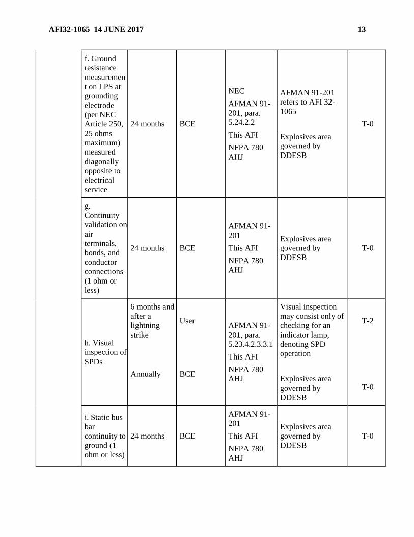
AFI32-1065 14 JUNE 2017 13
f. Ground
resistance
measuremen
t on LPS at
grounding
electrode
(per NEC
Article 250,
25 ohms
maximum)
measured
diagonally
opposite to
electrical
service
24 months BCE
NEC
AFMAN 91-
201, para.
5.24.2.2
This AFI
NFPA 780
AHJ
AFMAN 91-201
refers to AFI 32-
1065
Explosives area
governed by
DDESB
T-0
g.
Continuity
validation on
air
terminals,
bonds, and
conductor
connections
(1 ohm or
less)
24 months BCE
AFMAN 91-
201
This AFI
NFPA 780
AHJ
Explosives area
governed by
DDESB
T-0
h. Visual
inspection of
SPDs
6 months and
after a
lightning
strike
User AFMAN 91-
201, para.
5.23.4.2.3.3.1
This AFI
NFPA 780
AHJ
Visual inspection
may consist only of
checking for an
indicator lamp,
denoting SPD
operation
Explosives area
governed by
DDESB
T-2
Annually BCE
T-0
i. Static bus
bar
continuity to
ground (1
ohm or less)
24 months BCE
AFMAN 91-
201
This AFI
NFPA 780
AHJ
Explosives area
governed by
DDESB
T-0
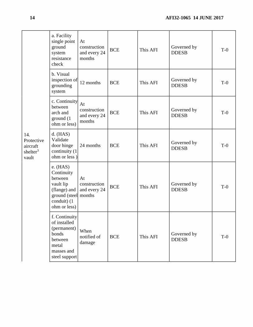
14 AFI32-1065 14 JUNE 2017
14.
Protective
aircraft
shelter3
vault
a. Facility
single point
ground
system
resistance
check
At
construction
and every 24
months
BCE This AFI Governed by
DDESB T-0
b. Visual
inspection of
grounding
system
12 months BCE This AFI Governed by
DDESB T-0
c. Continuity
between
arch and
ground (1
ohm or less)
At
construction
and every 24
months
BCE This AFI Governed by
DDESB T-0
d. (HAS)
Validate
door hinge
continuity (1
ohm or less )
24 months BCE This AFI Governed by
DDESB T-0
e. (HAS)
Continuity
between
vault lip
(flange) and
ground (steel
conduit) (1
ohm or less)
At
construction
and every 24
months
BCE This AFI Governed by
DDESB T-0
f. Continuity
of installed
(permanent)
bonds
between
metal
masses and
steel support
When
notified of
damage
BCE This AFI Governed by
DDESB T-0

AFI32-1065 14 JUNE 2017 15
g. Visual
inspection of
permanent
bonds
between
metal
masses and
steel support
Annually BCE This AFI Governed by
DDESB T-0
15. Medical
facilities4
a. Ground
resistance
validation
(Per NEC
Article 250,
25 ohms or
less at
service
grounding
electrode)
5 years BCE NFPA 99 T-3
b.
Effectivenes
s of
grounding
system by
voltage and
impedance
measuremen
t s
Before
acceptance of
new facility
or after
service
entrance
modification
BCE NFPA 99 T-0
c.
Verification
of continuity
of receptacle
grounding
circuits
Annually
(semi-
annually for
critical care
areas)
BCE NEC T-0
16. Airfield
lighting
vault single
point facility
ground
Ground
resistance
check (Per
NEC Article
250, 25
ohms or
less)
2 years BCE This AFI T-2

16 AFI32-1065 14 JUNE 2017
17. EMP
hardened
facilities
(These
facilities
may have
special
requirements
) Otherwise,
resistance
check (Per
NEC Article
250, 25
ohms or less
at service
grounding
electrode)
2 years
User
BCE
DNA-A-86-
60, Vol 1-3
This AFI
T-3
T-2
18. PMEL
a. Visual
inspection of
equipment
bonds
Before each
use User This AFI T-3
b.
Continuity
and
resistance
test of
facility
ground (Per
NEC Article
250, 10
ohms or less
at service
grounding
electrode)
5 years BCE This AFI FC 4-218-01F T-2
19. Special
intelligence,
cyber, SCIF,
UAS/RPA,
launch and
space, and
other
special-use
facilities4
a. TBD by
AHJ
This block is
intentionally
blank
BCE
This block is
intentionally
blank
b. TBD by
AHJ
This block is
intentionally
blank
User
This block is
intentionally
blank

AFI32-1065 14 JUNE 2017 17
20. Surge
protective
devices
a. Visual
inspection
After
unscheduled
power
outages
(report
outage to
BCE)
User This AFI
NFPA 780
User is onsite. A
quick check and
report to BCE may
avoid additional
damage until BCE
can arrive.
T-0
b. Visual
inspection
After
unscheduled
power
outages and
annually
BCE This AFI
NFPA 780 T-0
1. If utility is privatized, this does not apply; however, safety and operational discrepancies
and damage should be reported when observed.
2. As defined in NEC Article 500.
3. Also known as hardened aircraft shelter (HAS), as determined by current Security Forces
AFIs.
4. BCE will perform if separate medical facility maintenance branch does not exist, under
memorandum of agreement (MOA) only.
5. T-0 requirements for explosives facilities and PAS/HAS is delegable from DDESB to
AFCEC/COSM.
Note: All incoming utility services should be verified for continuity of grounding and bonding
by the service provider every 5 years (i.e., gas, telephone, signal lines, CATV), including
government-owned facilities/systems.
2. Codes and Specifications. The BCE or user will follow applicable codes and specifications
in Attachment 1 unless modified in this instruction, or deviations are justified due to local
conditions. (T-1).
3. Required Maintenance. The BCE or user will perform required maintenance at the
frequencies specified in Table 1. When possible, plan for and schedule maintenance when
facility users will be least affected. (T-1).
4. Recordkeeping and Review for Explosives Facilities.
4.1. Inspectors and testers must compile and maintain records of their inspections and tests.
(T-1). Records should including the following (sample records are provided in Attachment
6, Figures A6.6, A6.7, A6.8, and A6.9):
4.1.1. A sketch of the grounding and lightning protection system showing test points and
where services enter the facility. The sketch should also show the location of the probes
during the ground resistance test. (Separate sketches are suggested for static, earth
ground, and lightning protection systems on large complex facilities. (See Figure A6.8
and Figure A6.9 for examples of sketches or drawings that contain required information.)

18 AFI32-1065 14 JUNE 2017
4.1.2. Date action was performed.
4.1.3. Inspector's or tester’s name.
4.1.4. General condition of air terminals, conductors, and other components.
4.1.5. General condition of corrosion protection measures.
4.1.6. Security of attachment for conductors and components.
4.1.7. Resistance measurements of the various parts of the ground terminal system.
4.1.8. Variations from the requirements of this instruction.
4.1.9. Discrepancies noted and corrective actions taken.
4.1.10. Dates of repairs.
4.2. The BCE will review records for deficiencies; also analyze the data for undesirable
trends. If test values differ substantially from previous or original tests obtained under the
same test procedure and conditions, determine the reason and make necessary repairs. (T-1).
4.3. Inspectors and testers will keep test and inspection records in accordance with DODD
6055.09-M-V2, Ammunition and Explosives Safety Standards. (T-1).
4.4. Mandatory Review and Update of Record Drawings for Nuclear-Capable Weapons
and Munitions Storage and Maintenance Facilities. Reproducible lightning protection
system drawings are required to be included in record drawings and available for immediate
use by AFSEC in initial and updated explosives site plans. The BCE will ensure the record
drawings contain:
4.4.1. Dimensions and material sizes for all lightning protection systems (LPS) materials
from top view and applicable elevations. (T-2).
4.4.2. Identification of test points. (T-2).
4.4.3. A 100-foot (30.5-meter) radius rolling sphere superimposed on elevations. (See
Figure A6.10 for a sample drawing.) (T-2).
4.5. Engineering Technical Letter (ETL) 11-28, Mandatory Review and Update of Record
Drawings for Nuclear-Capable Weapons and Munitions Storage and Maintenance Facilities,
required completion of this review of LPS drawings meeting the requirements in paragraphs
4.4.1 through 4.4.3 for existing system drawings by 15 June 2012.
4.6. No ongoing or currently active project (awarded or under design) on nuclear, nuclear-
capable, or munitions storage areas (WSA and MSA) shall be accepted until drawings are
delivered to and approved by the BCE or his/her written designated representative. Drawings
must meet American National Standards Institute (ANSI), Architectural Graphic Standards
(AGS), and Architectural Engineering and Construction (AEC) standards for content,
abbreviations, reproducibility, and graphics. A signature by the BCE or his/her designated
representative is required as proof of receipt and approval of as-built drawings. (T-2).
4.7. The contract for a lightning protection system project, or for any project on a facility
containing a lightning protection system, shall require an LPS inspection by other than the
designer and installer, prior to acceptance of the project. This may be accomplished by
compliance with UFC 3-575-01, paragraph 3-1, third-party inspection requirements, or by

AFI32-1065 14 JUNE 2017 19
advanced government training, as outlined in paragraph 6.2, this AFI. Projects calling for a
facility addition, with or without addition to the existing LPS, shall consider the
configuration of the overall facility LPS in the design. Projects of this type shall ensure the
final LPS as a whole is compliant with AFI 32-1065 and NFPA 780, in that priority order.
(T-2) Paragraph 12 of this AFI applies for facilities housing explosives, whether permanent
or temporary. See AFMAN 91-201 for testing requirements. (T-0).
5. Forms. Inspectors and testers will provide copies of completed forms to the facility user, for
munitions facilities maintained by host nation civil engineers, the using agency must receive a
copy of the completed forms. (T-1). Sample forms for inspection and test records are provided
in Attachment 6, Figures A6.6 and A6.7. Either the sample forms or the Air Force General
Purpose Form (3100 series) may be used to record test results for other-than-explosives facilities.
6. Personnel Qualifications.
6.1. General Qualifications. Workers maintaining, repairing, modifying, and testing
grounding systems must be thoroughly familiar with test equipment operation, lightning
protection, grounding, bonding theory, practices, referenced codes, standards, specific
requirements, and procedures in this instruction. DAC course number 4E-F37 645-F21
(formerly referred to as AMMO-47), AMMO-48, or an official on-the-job (OJT) program, If
OJT is selected, the trainee must be instructed and mentored by a worker who has completed
AMMO-47 or AMMO-48 within the last three years, and training milestones comparable to
those in formal training must be tracked and documented by the electrical superintendent.
Minimum OJT program is 6 months. Workers will renew maintenance training every three
years, +/- one month. One person with completion of AMMO-47 or AMMO-48 within the
past three years must be part of the electrical shop at all times. (T-2). Attachments 2 through
6 provide information suitable for use in training and familiarization.
6.2. Advanced Qualifications. In addition to general qualifications, government personnel
may meet the third party inspector requirements in paragraph 4.7 with additional training.
Government personnel responsible for inspection and acceptance of contracts, including
SABER contracts, on facilities with LPS installation have the following requirements. For
official (designated in writing by the BCE) CE inspectors, advanced qualifications shall be
renewed every three years. Air Force Reserve Command (AFRC) units and the Air National
Guard (ANG) may comply with UFC 3-575-01, Lightning and Static Electricity Protection
Systems, in lieu of these advanced qualifications, by complying with paragraph 3-1, for a
third-party inspector. (T-1).
6.2.1. Qualifications in paragraph 6.1 as a pre-requisite.
6.2.2. Attendance and completion of the Senior Inspector AMMO-50 course, or
equivalent, with completion certificate. AFCEC/CO must approve the equivalent course,
based on content, prior to participation. An equivalent course would be one in which all
topics in AMMO-50 are covered, all codes and references in AMMO-50 are addressed, a
class field inspection is conducted for the purpose of identifying real-world common
discrepancies, and “certification” must be conditional upon passing a graded, four-hour
examination, which includes an LPS design, essay questions, and code/ Air Force criteria
(with focus on this AFI) based questions. A certificate of completion and competency
within three years prior to the inspection is required.

20 AFI32-1065 14 JUNE 2017
6.2.3. Air Force Specialty Code (AFSC) 3E0X1, 7-level, with training commensurate
with that level of expertise and experience or, for civilians, training and experience
equivalent to this AFSC.
6.2.4. Proficiency using test equipment required to obtain test readings for inspections
referenced in this instruction.
6.3. Project Acceptance Qualifications. Air Force-approved inspectors, with authority to
recommend acceptance of LPSs that protect explosives facilities and communications
facilities, are limited to:
6.3.1. Nationally recognized inspection agencies who have a minimum 10 years of
experience in inspection of LPS for explosives facilities on DOD or Department of
Energy (DOE) installations and have exhibited accuracy in identifying discrepancies,
evidenced by no modifications having been required for the system during the warranty
period (see UFC 3-575-01). Discrepancies must not be listed on any database with public
access. (T-1).
6.3.2. Air Force personnel with a minimum six years of experience in LPS maintenance
and have taken an advanced lightning protection systems senior inspector course
approved by the Air Force. (T-2).
6.3.3. Air Force-contracted maintenance personnel (BOS or other contracted
maintenance to government-owned facilities) shall meet the experience levels of
paragraph 6.3.2. (T-2).
6.4. IG and Nuclear Surety. Qualifications required for Nuclear Surety Inspections (NSI),
Nuclear Surety Staff Assistance Visits (NSSAV), and Initial Nuclear Surety Inspection
(INSI) of nuclear facilities:
6.4.1. Military must:
6.4.1.1. Attend and complete the initial Air Force Inspection Agency inspector’s
course. (T-1).
6.4.1.2. Attend and complete the AMMO-47, AMMO-48, or equivalent experience,
with completion certificate or supervisor memorandum of qualification on file. (T-1).
6.4.1.3. Attend and complete an advanced commercial lightning protection course
per paragraph 6.2.2. (T-1).
6.4.1.4. AFSC 3E0X1, 7-level, with training and experience commensurate to that
intended level of expertise. (T-1).
6.4.1.5. Proficiency using test equipment required to obtain test readings for
inspections referenced in this instruction, validated in writing by a supervisor. (T-1).
6.4.2. Civilian must:
6.4.2.1. Attend and complete AMMO-47, AMMO-48, or equivalent experience, with
completion certificate or supervisor memorandum of qualification on file. (T-1).
6.4.2.2. Attend and complete an advanced commercial lightning protection course
per paragraph 6.2.2. (T-1).

AFI32-1065 14 JUNE 2017 21
6.4.2.3. Have 10 years of experience in maintenance and inspection of LPS in a field
equivalent to AFSC 3E0X1, 7-level. (T-1).
6.4.2.4. Proficiency using test equipment required to obtain test readings for
inspections referenced in this instruction, validated in writing by a supervisor. (T-1).
7. Developing Procedures. The organization performing inspections and tests must develop
standard procedures based on the requirements in this instruction. To avoid potential security
issues, inspection information providing the facility name, facility number, street address, and/or
base on which the facility is located must not be posted to any site available for public access.
(T-0).
Section B—Grounding Resistance and Continuity Tests and Visual Inspections
8. Testing Requirements. See Attachment 6 for resistance and continuity test requirements for
typical systems. Instruments must be able to measure 10 ohms +10 percent for ground resistance
tests and 1 ohm +10 percent for continuity testing. Only instruments designed specifically for
earth-ground systems are acceptable for ground resistance testing. Follow the manufacturer’s
instruction manual except as modified herein when using the instruments. Earth-ground
resistance should be less than 25 ohms at the service grounding electrode unless otherwise
specified in this instruction. Note. The National Electrical Code (Articles 250.52 and 250.53)
does not require 25 ohms to ground for a ground ring (counterpoise), therefore, ground rings are
not required to be tested for resistance; resistance test requirements are for the grounding
electrodes bonded to the ground ring. Continuity testing is required for the ground ring
(counterpoise). Periodic tests should be made at approximately the same time each year to
minimize distortions to readings resulting from seasonal changes (see Attachment 2). If the
resistance measured during continuity tests is greater than 1 ohm, check for deficiencies, repair,
then retest. When performing a continuity test over very long lengths of conductors (more than
65 feet [20 meters] with no parallel paths), readings above 1 ohm but less than 3 ohms may
occur. This can be due to the added resistance of the test wire and is acceptable. Documentation
is required for the file. The base electrical engineer may modify the test procedures to
compensate for local conditions as long as the intent of the test is still met.
9. Visual Inspections of Lightning Protection Systems. Inspector will inspect all visible parts
of the system. (T-1). Pulling or tugging on conductors and connections to ensure soundness is a
necessary part of these inspections, but be careful not to damage the system in the process.
Visual/physical inspection must determine if:
9.1. The system is in good repair.
9.2. Loose connections might be causing high-resistance joints.
9.3. Corrosion or vibration has weakened any part of the system.
9.4. Down conductors, roof conductors, ground terminals and all other components are
intact, air terminals exceeding 24 inches in length are supported at a point not less than one-
half their length, and no components or fasteners are missing.
9.5. Braided bonding wires or straps are excessively frayed (cross-sectional area reduced by
half).

22 AFI32-1065 14 JUNE 2017
9.6. Ground wires/down conductors, air terminals (for earth-covered magazines [ECM]),
masts, or poles are/have been damaged by mowers, equipment, or vehicles.
9.7. Conductors and system components are securely fastened to mounting surfaces. Position
connections to better protect against accidental displacement. Adhesive-type fasteners are not
allowed.
9.8. Project additions or alterations to the protected structure require additional protection.
See UFC 3-575-01.
9.9. Surge protective devices (SPDs) supporting facilities and facility service appear
damaged or indicator lamps signal an operation has occurred. Note: Inspection, repair, and
replacement of SPDs protecting equipment are the responsibility of the equipment owner or
user.
9.10. The system complies with the intent of applicable sections of the most recent version
of NFPA 780, Standard for the Installation of Lightning Protection Systems, unless otherwise
noted in this AFI. (T-1).
10. Visual Inspection of Facility Grounds. Unless otherwise specified by references in Table
1, conduct visual inspections as follows. Inspect all visible and accessible parts of the facility
grounding system. Validate satisfactory condition and verify the installation meets NEC
requirements (T-1). Typical items to check include:
10.1. The system is in good repair.
10.2. No loose connections are visible.
10.3. The system neutral is grounded at the service entrance. This may be achieved either by
bonding the neutral bus to the ground bus in the main distribution panel or by connection to
the grounding electrode (single point ground) for the facility.
10.4. Separately derived systems are properly grounded.
10.5. Flashover protection (bonding) is installed on insulating fittings on underground
metallic pipelines entering the facility.
10.6. Grounding systems and static systems within the facility are bonded together at floor
level or at or below ground level outside the building.
Section C—Grounding and Lightning Protection Requirements
11. Introduction. This section covers requirements for grounding and lightning protection
systems, including systems installed on or in areas such as explosives buildings, magazines,
operating locations, and aircraft shelters. Use these requirements when inspecting to determine
compliance and when repairing or modifying systems. See AFMAN 91-201, Explosive Safety
Standards.
12. Testing and Inspecting Static and Lightning Protection Systems and Grounding.
12.1. Procedures. Use Attachment 4 and Attachment 5 as a guide for establishing proper
maintenance procedures and as a self-check prior to inspections.
12.2. Inspection and Testing. Visually inspect and test the static, grounding, and lightning
protection systems for buildings and facilities in accordance with Section A, Maintenance

AFI32-1065 14 JUNE 2017 23
Policy, and Section B, Grounding Resistance and Continuity Tests and Visual Inspections,
and the special requirements in this section. (T-1).
12.3. Records. Inspectors and testers will keep test and inspection records in accordance
with DODD 6055.09-M-V2, Ammunition and Explosives Safety Standards for a minimum of
six inspection cycles. (T-1). Figure 1 is an example sketch of a grounding and lightning
protection system with test points.
Figure 1. Example Sketch of Test Points (Typical).

24 AFI32-1065 14 JUNE 2017
13. Static Protection.
13.1. Static Protection for Electronics and Electrical Equipment. The best methods to
eliminate or reduce the hazard from static electricity are bonding and grounding. Bonding
minimizes potential differences between conductive objects. Grounding minimizes potential
differences between objects and the ground. Inspectors will inspect and test facilities for
compliance with NFPA 77, Static Electricity, which contains the minimum acceptable static
grounding and bonding requirements for Air Force activities, except as modified in this AFI.
(T-0). See Attachment 3.
13.1.1. Bonding conductors shall be large enough to withstand mechanical damage.
Minimum size for existing bonding conductors is AWG No. 8. If bonding conductors are
in areas of high use or are subject to physical damage, make repairs with wires no smaller
than AWG No. 6 copper. Static grounds for portable or movable equipment must be of
braided cable for added flexibility. (T-0).
13.1.2. Static grounds shall be 10,000 ohms to ground or less, unless otherwise stated.
Static electricity creates extremely small (on the magnitude of milliamps) currents, so
even this large resistance is small enough to bleed off static charges. But because the
static grounding system must be connected to the facility grounding system, resistances
of less than 25 ohms are common. (T-0).
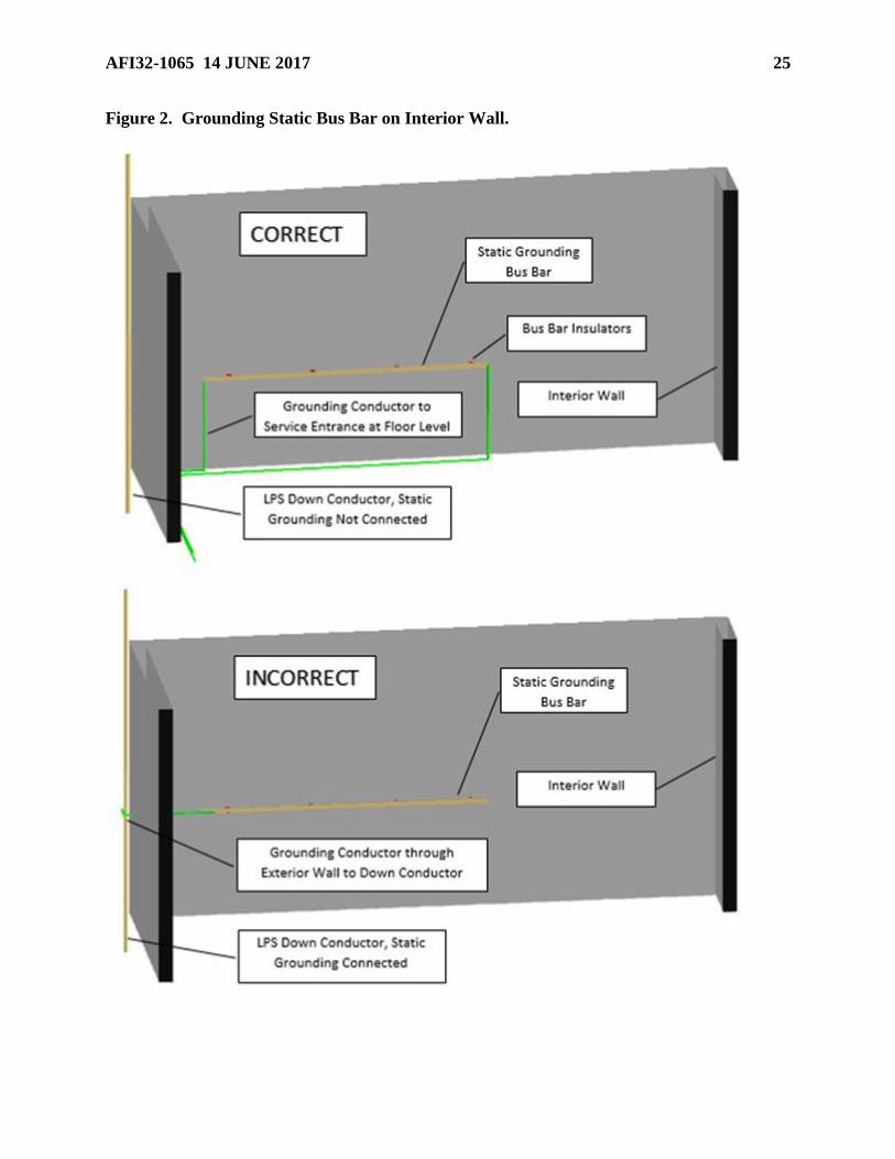
13.2. Static Bus Bars. Static bus bars are usually 2-inch by 0.25-inch copper bars installed
on the interior wall of the facility. The length will vary for new facilities but design the bar
itself to be no closer than 12 inches from the intersection of an interior wall with an exterior
wall for side-flash reasons. See Figure 2 for bus bar end and for transition at floor level,
around windows, and doorways (requires depression for ground wire). Design the down
conductor location so that it does not “cross” an interior static bus bar. For existing facilities
at which this condition exists, perform side-flash calculations to ensure that the wall
thickness exceeds the side flash distance. Typically, the side flash distance through the wall,
using the basic bonding formula (BBF), exceeds the calculated side-flash distance at the
normal static bus bar height up to 48 inches (1.2 meters). If installed within side flash
distance, relocate either the down conductor or discontinue the static bus bar 1 foot (0.3
meter) either side of the exterior down conductor location and bond the two sections of the
static bus bar at floor level, using a 1/0 copper conductor. Note: For structures exceeding 250
feet (76 meters) in perimeter, if relocating the down conductor results in a separation distance
of greater than 100 feet (30.5 meters) between down conductors, an additional down
conductor may be necessary. The grounding conductor from the static bus bar shall be
connected directly to the facility grounding electrode system. See Attachment 6 for testing
requirements. Use static bus bars only for static grounding. Communications systems,
electrical conduit, intrusion detection systems, and other permanently installed systems shall
not use the static bus bar as a system ground. As a general rule, do not connect a static bus to
any facility metal body or use this bus to ground structural components of a facility;
however, coincidental connections of the bus bar through its anchoring/mounting system are
acceptable, as is the mounting of the static bars on the skin of a metal structure. Portable
grounding straps from equipment to the static grounding bus are not real property; therefore,
visual inspections and continuity checks for these straps are the responsibility of the user. (T-
0).
AFI32-1065 14 JUNE 2017 25
Figure 2. Grounding Static Bus Bar on Interior Wall.

26 AFI32-1065 14 JUNE 2017
13.3. Belting Requirements. On equipment such as belt-driven compressors and conveyor
belts, if static electricity is a hazard, use non-static-producing belting. Belting must have a
resistance not exceeding 1,000,000 ohms when measured according to IEEE Standard 142,
IEEE Recommended Practice for Grounding for Industrial and Commercial Power Systems
(Green Book), Chapter 3. (T-0).
13.4. Conductive Floor Grounds. If the electronic equipment within a facility requires a
resistance of the floor-to-ground of less than 1,000,000 ohms, a conductive floor is required.
This resistance value is the sum of the resistance of the floor plus a person, added together.
Static dissipative footwear (PPE) will ensure protection for personnel from electric shock
hazard and will allow bleed-off of static buildup in personnel and equipment. Testing
requirements are in the appendices of this document. Using agency must keep a record of
test results. (T-1).
14. Lightning Protection Systems. The following requirements will be used as a guide for
facilities that require or possess lightning protection. (T-1).
14.1. General. Systems must comply with NFPA 780 and UFC 3-575-01, whichever is
more restrictive (except as modified herein). (T-0). See Attachment 4. Early streamer
emission systems, charge dissipation systems, or other unconventional systems are not
permitted. Parts and materials must carry the Underwriters Laboratories (UL) label or
equivalent, and must be listed for use on lightning protection systems. (T-0). Components not
carrying a UL label or equivalent, or components carrying a UL label or equivalent and not
listed for use on lightning protection systems, must be approved by the BCE or designated
representative. (T-2). Facilities in foreign countries may use host nation codes and standards
if they offer equivalent protection, as determined by the BCE, with concurrence from
AFCEC/COSM and, for facilities housing explosives, approval of the DOD Explosive Safety
Board (DDESB). (T-0). Otherwise, the status of forces agreement (SOFA) must specifically
permit the use of host nation codes. Where the SOFA requires compliance with host nation
codes, translate those required codes into English, make them available to all appropriate
personnel, and conduct necessary training. Maintain all installed systems in accordance with
this instruction. If an existing lightning protection system is no longer required, coordinate
with the facility manager to remove the LPS. Test records of the LPS must remain with the
facility for six inspection cycles. (T-1).
14.2. Bonding Requirements. Adequate bonding is more important than grounding.
Bonding ensures all metallic objects are at equal potentials to protect personnel against
dangerous arcs or flashovers. Inspectors will inspect and test facilities for compliance with
NFPA 780 and Attachment 3 (T-0).
14.3. Resistance to Ground. Low resistance is desirable but not essential for lightning
protection. For most facilities and per NEC Article 250.53, resistance to ground should be
less than 25 ohms at the service grounding electrode. If 25 ohms cannot be achieved with the
addition of a grounding electrode, a supplemental electrode may be necessary, depending
upon the magnitude of resistance obtained and the contents of a facility being protected. The
resistance to ground of a ground loop conductor is acceptable even if greater than 25 ohms.
See Attachment 2.

AFI32-1065 14 JUNE 2017 27
14.4. Lightning Protection for Explosives Facilities. AFMAN 91-201 identifies
explosives facilities that require lightning protection systems. Use the basic practices in
Attachment 4, with the following additions:
14.4.1. The system shall be designed for a 100-foot (30.5-meter) striking distance. (T-0).
Note: an administrative, educational, or other non-explosives-type facility located within
a weapons or munitions storage area may be designed for a 150-foot (45.7-meter) striking
distance.
14.4.2. Installation of test wells or hand holes at corner grounding electrodes for existing
connections to grounding electrodes is recommended to aid with access for testing unless
conductors are exothermically welded to the grounding electrode and the exothermic
weld is shown on record drawings.
14.4.3. Replace existing bolted connectors on down conductors and roof conductors,
when in need of repair, with high compression or exothermic-weld type connectors.
Connections to air terminals are an exception, but they must be tight and in good repair.
Bolted connections to aluminum bodies (such as vents) and to metal bodies for the
purpose of bonding are also acceptable. Brazing to metal bodies is not allowed for new
construction due to the possibility of a cold weld with inadequate strength. (T-0).
14.4.4. The metal framework of a structure shall be permitted to be utilized as an air
terminal and main conductor of a lightning protection system if it is equal to or greater
than 3⁄16 (0.188) inch (4.8 millimeters) in thickness and is electrically continuous, either
inherently or made. (T-0).
14.5. Explosives Facility with Large Perimeter. New explosives facilities with a
perimeter over 300 feet (91.4 meters) that require lightning protection and do not use the
structural steel as an air terminal equivalent shall use either a mast system or an overhead
wire system. See Attachment 4 for requirements. Such indirect air terminal designs are
intended to provide lightning attachment away from the facility and not directly to the
facility. It also reduces maintenance and installation costs. The BCE may waive this
requirement (overhead or mast system). ECMs are not required to carry air terminals from
headwall to headwall (for drive-through ECMs) or from headwall to air vent. (T-2).

28 AFI32-1065 14 JUNE 2017
Figure 3. ECM With Center Conductor and Air Terminals.

AFI32-1065 14 JUNE 2017 29
Figure 4. ECM Without Center Conductor and Air Terminals.

30 AFI32-1065 14 JUNE 2017
14.6. Sunshades. The metal framework of a sunshade structure shall be permitted to be
utilized as an air terminal and main conductor of a lightning protection system if structural
members are equal to or greater than 3⁄16 (0.188) inch (4.8 millimeters) in thickness and
structural members are electrically continuous (either inherent or made) to ground.
Grounding requirements depend upon the footing of the vertical support units (columns).
Vertical support units with full footers require no further grounding. The flight line (to
include sunshade areas) is evacuated once lightning is at a distance (in nautical miles [NM])
determined by the base; therefore, step potential is not considered for sunshades. Vertical
support units bolted to the apron concrete make it necessary to, as a minimum, install one
grounding electrode at two diagonally opposite corners. Roof material, whether metallic or
fabric, is of no consequence when considering the steel structure as a lightning protection
system.
14.7. Protective Aircraft Shelters (PAS) (also known as Hardened Aircraft Shelter
[HAS]). Aircraft shelters with continuous interior steel arches, either visible or validated by
record drawings, provides a Faraday-like shield and therefore requires no air terminals.
Exterior metallic ventilators with an enclosure at least 3/16 (0.188) inch (4.8 millimeters) in
thickness do not require air terminals if properly bonded to the steel arch. Metallic ventilators
less than 3/16 (0.188) inch (4.8 mm) in thickness must be protected by an air terminal bonded
to the steel arch in accordance with NFPA 780. All metal bodies mounted to the steel arch
shall be bonded and grounded in accordance with this instruction and NFPA 780. The facility
grounding system shall also comply with this instruction and NFPA 780. Since the floor is
designed to be separable from the walls, the walls and the floor shall be permanently bonded
to a single grounding point or series of connected grounding points identified on record
drawings. If no record drawings are available, continuity shall be validated by a minimum of
four shell-to-ground tests interior to the facility. A sketch will be made, indicating test points,
and this shall become the record drawing. Visual inspection will be conducted every 12
months and testing will be conducted every 24 months. (T-0).
15. Surge Protection. Surge protection is required on electrical service entrances and on some
interior distribution panels in accordance with NFPA 780. (T-0). SPD, formerly referred to as
TVSS (transient voltage surge suppression), protect facilities and facility contents from transient
voltages resulting from lightning surges, switching surges, and surges internal to the facility
caused by mechanical and user-owned electronic devices and equipment, and may protect the
upstream distribution system from the rapid switching effects of user-owned electronics. For
large facilities, SPDs are most effective when used in the form of tiered protection. Tiered
protection means providing protection at main distribution panels, at secondary or sub-panels,
and at the equipment point of use. For protection of non-real property installed equipment, refer
to the equipment manufacturers’ requirements for surge protection (the equipment users fund
purchase, installation and maintenance of any surge protective devices required for the protection
of communications and other equipment or desired by the user for additional protection of
communications and other equipment). In facilities such as dormitories and other facilities with
basic/minimal electronics, low-dollar contents, and/or minimal occupants, surge protection may
meet the requirement for a lightning protection system.

AFI32-1065 14 JUNE 2017 31
15.1. WSAs, MSAs, and Communications Facilities:
15.1.1. Standard, published, minimum 10-year unlimited replacement warranty on
product (SPD). The entire unit shall be replaced upon detection of the failure of any
mode. (T-1).
15.1.2. All mode (10 modes), directly connected protection elements (l-n, l-g, l-l, n-g).
Direct clamping l-n and l-l is required. (T-1).
15.1.3. F1 polycarbonate enclosure or NEMA 4 or 4X steel enclosure: Inaccessible to
unqualified persons. (T-1).
15.1.4. Internal over-current fusing on each phase for self-protection from failed
component(s) and an internal disconnect for each phase. (T-1).
15.1.5. Individual component level thermal fusing. (T-1).
15.1.6. Bi-polar protection. (T-1).
15.1.7. The SPD shall contain continuous self-monitoring devices with indicator lamps
for each mode. (T-1). These may be located inside enclosed areas such as mechanical
rooms if an indicator lamp is provided in a visible area. It would be preferable for the
indicator lamp to be installed in a location that can be seen from a vehicle, allowing
maintenance personnel to drive through large areas and quickly identify devices that have
operated. Indicator lamps that can be seen in this way will also allow maintenance
personnel to assess whether a group of SPDs in a single area have operated.
15.1.8. Cable connection between a bus and SPD shall be minimum No. 10 AWG for
installation at main distribution panels and sub-panels. (T-1).
15.2. Igloos or ECMs: Up to 60A service.
15.2.1. Visible indicators of SPD operation on the exterior of facilities. Drive-by visual
inspections may be an effective means of inspecting SPDs.
15.2.2. 60kA/mode to allow the following requirement.
15.2.3. 180kA/phase peak service surge current.
15.2.4. Non-modular. The entire unit shall be replaced upon detection of the failure of
one mode of operation. Ease of installation shall not be traded for possible minimized
protection level. (T-1).
15.3. Maintenance Facilities: 400-600A service. (T-1).
15.3.1. Visible indicators of SPD operation on the exterior of facilities. Drive-by visual
inspections may be an effective means of inspecting SPDs.
15.3.2. 180kA/mode to allow the following requirement.
15.3.3. 240kA/phase peak service surge current.
15.3.4. Non-modular. The entire unit shall be replaced upon detection of the failure of
one mode of operation. Ease of installation shall not be traded for possible minimized
protection level. (T-1).

32 AFI32-1065 14 JUNE 2017
15.4. Communications Facilities: Up to 1800A.
15.4.1. Visible indicators of SPD operation on the exterior of facilities or audible alarm.
15.4.2. 200kA/mode to allow the following requirement.
15.4.3. 600kA/phase peak service surge current.
15.4.4. Non-modular. The entire unit shall be replaced upon detection of the failure of
one mode of operation. Ease of installation shall not be traded for possible minimized
protection level.
15.5. General Requirements:
15.5.1. Nominal discharge current test at 20kA (UL testing allows 10kA or 20kA, but
testing at 10kA is not allowed for Air Force facilities). (T-0).
15.5.2. Unit type (NFPA 70, NEC, Article 285): (T-0).
15.5.2.1. Type 1 unit is required for the supply side of the service or building
disconnect means. (T-0).
15.5.2.2. Type 2 or 3 units, when required by the equipment, must be installed on the
load side of the overcurrent protective devices (not needed for igloos). (T-0).
15.6. User Requirements: SPDs shall be provided on proprietary equipment by the
communications provider or the tenant communications agency or group. (T-1).
JOHN B. COOPER, Lieutenant General, USAF
DCS/Logistics, Engineering & Force Protection

AFI32-1065 14 JUNE 2017 33
Attachment 1
GLOSSARY OF REFERENCES AND SUPPORTING INFORMATION
References
10 USC 8013, Secretary of the Air Force
7 CFR 1724.50, Compliance with National Electrical Safety Code
14 CFR 420.71, Lightning Protection
29 CFR 1910, Electrical Standards – Final Rule
29 CFR 1910, Occupational Safety and Health Standards
29 CFR 56.12069, Lightning Protection for Telephone Wires and Ungrounded Conductors
DOD 6055.09M, Vol. 2, DoD Ammunition and Explosives Safety, April 2012
Department of Defense Explosives Safety Board Technical Paper 22 (DDESB TP-22), Lightning
Protection for Explosives Facilities
AFPD 32-10, Installations and Facilities, 4 March 2010
AFI 32-1062, Electrical Power Systems, 15 January 2015
AFI 91-203, Air Force Consolidated Occupational Safety Instruction, 15 June 2012
AFMAN 91-201, Explosives Safety Standards, 12 January 2011
DNA-A-86-60, V1-3, DNA EMP Engineering Handbook for Ground-Based Facilities, 1986
ETL 11-28, Mandatory Review and Update of Record Drawings for Nuclear-Capable Weapons
and Munitions Storage and Maintenance Facilities, 7 December 2011
ETL 12-9, Personnel Certification Requirements for Inspection of Lightning Protection Systems
(LPS) on Nuclear Weapons Maintenance, Handling, and Storage Facilities, 13 Apr 2012
FC 4-218-01F, Criteria For Precision Measurement Equipment Laboratory Design And
Construction, 28 October 2015
Federal Information Processing Standards (FIPS) Pub 94, Guidelines on Electrical Power for
ADP Installations, 1983
IEEE STD 1100, IEEE Recommended Practice for Powering and Grounding Electronic
Equipment (Emerald Book), 2005
IEEE STD 142, IEEE Recommended Practice for Grounding for Industrial and Commercial
Power Systems (Green Book), 2007
IEEE STD 446, IEEE Recommended Practice for Emergency and Standby Power Systems for
Industrial and Commercial Applications (Orange Book), 1995
IEEE STD 81, IEEE Guide for Measuring Earth Resistivity, Ground Impedance, and Earth
Surface Potentials of a Ground System, 2012
MIL-HDBK-419A, Grounding, Bonding, and Shielding for Electronic Equipment and Facilities,
29 December 1987

34 AFI32-1065 14 JUNE 2017
NETA MTS, Standard for Maintenance Testing Specifications for Electrical Power Equipment
and Systems, 2015, www.netaworld.org/standards/ansi-neta-mts
NFPA 70, The National Electrical Code (NEC), 2014
NFPA 77, Static Electricity, 2014
NFPA 780, Standard for the Installation of Lightning Protection Systems, 2014
NFPA 99, Health Care Facilities Code, 2015
UFC 3-460-03, Operation and Maintenance of Petroleum Systems, 21 January 2003
UFC 3-501-01, Electrical Engineering, 6 October 2015
UFC 3-520-01, Interior Electrical Systems, 6 October 2015
UFC 3-550-01, Exterior Electrical Power Distribution, 3 February 2010
UFC 3-575-01, Lightning and Static Electricity Protection Systems, 1 July 2012
UFC 3-580-01, Telecommunications Building Cabling Systems Planning and Design, 22 June
2007
Prescribed Forms
None.
Adopted Forms
None.
Abbreviations and Acronyms
A—Ampere
ac—Alternating Current
AF/A4C—Air Force Director of Civil Engineers
AFCEC/CO—Air Force Civil Engineer Center, Operations Directorate
AFCEC/COSM—Air Force Civil Engineer Center, Mechanical Engineering
AFI—Air Force Instruction
AFMAN—Air Force Manual
AFPD—Air Force Policy Directive
AFSEC—Air Force Safety Center
AHJ—Authority Having Jurisdiction
ANSI—American National Standards Institute
AWG—American wire gauge
BBF—basic bonding formula
BCE—Base Civil Engineer
AFI32-1065 14 JUNE 2017 35
BOS—Base Operations Support
CATV—Cable Television
cc—Carbon Copy
CE—Civil Engineering
DAC—Defense Ammunition Center
dc—Direct Current
DDESB TP—Department of Defense Explosives Safety Board Technical Paper
ECM—Earth-Covered Magazine
EMP—electromagnetic pulse
ETL—Engineering Technical Letter
FC—Facilities Criteria
FIPS—Federal Information Processing Standard
ft—Foot
HAS—hardened aircraft shelter
HVAC—Heating, Ventilation, Air-Conditioning
IAW—In Accordance With
IEEE—Institute of Electrical and Electronics Engineers
kA—Kiloampere
kV—Kilovolt
LOX—liquid oxygen
LPS—Lightning Protection System
MIL HDBK—Military Handbook
m—Meter
mm—Millimeter
MSA—Munitions Storage Area
NEC—National Electrical Code
NEMA—National Electrical Manufacturers Association
NFPA—National Fire Protection Association
NETA MTS—InterNational Electrical Testing Association Maintenance Testing Specifications
ohms-cm—Ohms Centimeter
PAS—Protective Aircraft Shelter (also known as Hardened Aircraft Shelter (HAS))
PMEL—Precision Measurement Equipment Laboratory

36 AFI32-1065 14 JUNE 2017
POL—petroleum, oils, lubricants
SABER—Simplified Acquisition of Base Engineer Requirements
SCIF—Sensitive Compartmented Information Facility
SDS—separately derived system
SOFA—Status of Forces Agreement
SPD—Surge Protective Device
T.O—Technical Order
TBD—To Be Determined
UAS/RPA—Unmanned Aerial System/Remotely Piloted Vehicle
UFC—Unified Facilities Criteria
UL—Underwriters Laboratories
Vac—Volts Alternating Current
V—Volt
WS3—Weapon Storage and Security System
WSA—Weapons Storage Area
Terms
Air Terminal—Alternate name for the device itself may be “lightning rod.” The component of a
lightning protection system intended to intercept lightning flashes, placed on or above a building,
structure, or tower. Note: A building’s grounded structural elements may function as an air
terminal. A main size conductor run across the top of a pole or mast may also function as an air
terminal if installed in such a way that the conductor across the top of the pole or mast is higher
than the cradle in which it is run.
Bonding—An electrical connection between two electrically conductive objects, made with the
intent of significantly reducing potential differences.
Conductor, Bonding—A conductor used to bring the potential between two metallic objects to
essentially zero.
Catenary System—A lightning protection system consisting of one or more poles or masts with
overhead wires between them. Each overhead wire may serve the function of both a strike
termination device and a main conductor. Also known as overhead wire system.
Conductor, Main—A conductor intended to carry lightning currents from the point of
interception to ground.
Copper-Clad Steel—Steel with a coating of copper bonded on it.
Down Conductor, Lightning—The conductor connecting roof conductors of an integral system,
overhead wires of a catenary system, or a mast system to the earth ground subsystem.

AFI32-1065 14 JUNE 2017 37
Equipment Grounding Conductor—The conductive path(s) that provides a ground-fault
current path and connects normally non-current-carrying metal parts of equipment together and
to the system grounded conductor or to the grounding electrode conductor, or both.
Facility Ground System—The electrically interconnected system of conductors and conductive
elements that provides multiple current paths to earth. The facility ground system can include the
earth electrode subsystem, lightning protection subsystem, signal reference protection subsystem,
fault protection subsystem, static ground subsystem, as well as the building structure, equipment
racks, cabinets, conduit, junction boxes, raceways, duct work, pipes, and other normally non-
current-carrying metal elements.
Frayed—When the cross-sectional area of the wire or braid is reduced by half.
Grounded (Grounding)—Connected (connecting) to ground or to a conductive body that
extends the ground connection.
Grounding Electrode—The portion of a lightning protection system, such as a ground rod,
ground plate electrode, or ground conductor, that is installed for the purpose of providing
electrical contact with the earth.
Ground Loop Conductor—A conductor, buried 3 to 8 feet (0.9 to 2.4 meters) from a structure,
encircling the structure and interconnecting grounding electrodes. The conductor may also be
connected to buried copper or steel plates or grounding electrodes which may have been installed
to establish a low-resistance contact with earth. (A ground loop conductor is also referred to as a
counterpoise, a loop conductor, or closed loop system.)
Inherent Bond (Inherently Bonded)—Where metal bodies located in a steel-framed structure
are electrically bonded to the structure through the construction, either by configuration or by
weight.
Integral System—A system which uses air terminals mounted directly on the structure to be
protected. Note: integral systems protect both the structure and its contents.
Labeled—Equipment or materials to which has been attached a label, symbol, or other
identifying mark of an organization that is acceptable to the AHJ and concerned with product
evaluation, that maintains periodic inspection of production of labeled equipment or materials,
and by whose labeling the manufacturer indicates compliance with appropriate standards or
performance in a specified manner.
Listed—Equipment, materials, or services included in a list published by an organization that is
acceptable to the AHJ and concerned with evaluation of products or services, that maintains
periodic inspection of production of listed equipment or materials or periodic evaluation of
services, and whose listing states that either the equipment, material, or service meets appropriate
designated standards or has been tested and found suitable for a specified purpose.
Lightning Rod—See Air Terminal.
Lightning Protection System—A complete system of strike termination devices, conductors
(which could include conductive structural members), grounding electrodes, interconnecting
conductors, surge protective devices (SPD), and other connectors and fittings required to
complete the system.
38 AFI32-1065 14 JUNE 2017
Mast System—A lightning protection system using masts that are remote from the structure to
provide the primary protection from a lightning strike. A mast system may be a single mast or
multiple masts.
Overhead Wire System—System using conductors routed over the facility, at a specified
height, designed to provide the required zone of protection. Also known as overhead shield wire
system and catenary system.
Side Flash—An electrical spark, caused by differences of potential, that occurs between
conductive metal bodies or between conductive metal bodies and a component of a lightning
protection system or ground.
Strike Termination Device—A conductive component of the lightning protection system
capable of receiving a lightning strike and providing a connection to a path to ground. Strike
termination devices include air terminals, metal masts, wooden masts with an air terminal atop,
permanent metal parts of structures, and overhead ground wires installed in catenary lightning
protection systems. A main size conductor looped over the top of a wooden mast may also
function as an air terminal.
Structure—(1) Metal-clad structure. A structure with sides or roof, or both, covered with metal.
(2) Metal-framed structure. A structure with electrically continuous structural members of
sufficient size to provide an electrical path equivalent to that of lightning conductors.
Surge Protective Device (SPD)—A device intended for limiting surge voltages on equipment
by diverting or limiting surge current that comprises at least one nonlinear component.
TEMPEST—Unclassified name for investigation/study of compromising emanation.
Third-party Inspector—An inspector who is neither the designer nor the installer.
Vac, VAC—Volts, alternating current
Zone of Protection—The space adjacent to a lightning protection system that is substantially
immune to direct lightning flashes.

AFI32-1065 14 JUNE 2017 39
Attachment 2
BASIC REQUIREMENTS FOR GROUNDING SYSTEMS
A2.1. Types of Grounds. There are five basic types of grounding systems which must be
inspected if present in a facility: static grounds, equipment grounds, electrical system grounds,
lightning grounds (down conductors), and signal reference grounds. (T-0). Subsystem grounds is
a hybrid of these five basic systems.
A2.1.1. Static Grounds. A static ground is a connection between a piece of equipment and
earth to drain off static electricity charges before they reach a sparking (discharge) potential.
Typically, static grounding involves connecting large metal objects such as fuel tanks or
aircraft to earth through a grounding electrode. Static grounds are not part of an electrical
power system, but if an equipment grounding conductor is adequate for power circuits it is
also adequate for static grounding.
A2.1.2. Equipment Grounds. Equipment grounding involves interconnecting and
connecting to earth all non-current-carrying metal parts of an electrical wiring system and
equipment connected to the system. The purpose of grounding equipment is to ensure
personnel safety by reducing any residual charge in an equipment item to near zero volts with
respect to ground. An equipment ground must be capable of carrying the maximum ground
fault current possible without causing a fire or explosive hazard until the circuit protective
device clears the fault. An example is the bare copper wire or green insulated conductor
connected to the frames of electric motors, breaker panels, and outlet boxes. The equipment
ground is connected to an electrical system ground (neutral) only at the electrical service
entrance of a building.
A2.1.3. Electrical System Ground (Single Point Facility Ground). The purpose of
electrical system grounds is to limit the voltage imposed by lightning, line/switching surges,
or unintentional contact with higher-voltage lines and to stabilize the voltage to earth during
normal operation. See NEC Article 250.4(A)(1). One wire or point of an electrical circuit in
an electrical system ground is connected to earth. This connection is usually at the electrical
neutral (though not always), and is called the "system ground" or “single point facility
ground.” The resistance of most electrical system ground electrodes operating at or below
600 Vac should not be more than 25 ohms. Medium voltage systems (1 to 15kV) frequently
are grounded through a resistor (or reactor) and may exceed 25 ohms. This practice limits
ground fault current to a manageable level. If a ground loop conductor functions as the
electrical system ground (single point facility ground) then 25 ohms is not a requirement.
A2.1.4. Lightning Grounds or Down Conductors. The purpose of a lightning protection
system is to provide for the safeguarding of persons and property from hazards arising from
exposure to lightning. Grounds and down conductors are necessary to safely dissipate
lightning strokes into the earth. They are part of a lightning protection system that usually
includes air terminals (lightning rods), main size conductors, arrestors, and other connectors
or fittings required for a complete system. It is helpful to provide test wells for access to the
grounding electrodes to test for continuity to the down conductor.

40 AFI32-1065 14 JUNE 2017
Figure A2.1. Test Well Configuration Example.
A2.1.5. Signal Reference Grounds. The purpose of a signal reference ground is to provide
a low impedance reference system for electronic equipment to minimize noise-induced
voltages (distortions on the voltage waveform) and thereby reduce equipment malfunctions.
Common configurations include planes and grids. See IEEE STD 1100-1999 Recommended
Practice for Powering and Grounding Electronic Equipment, for details. With the exception
of the connection point to the facility grounding system, the responsibility for individual
signal reference ground testing lies with the equipment owners.
A2.1.6. Subsystem Grounds. Each of the grounding systems described above may be a
subsystem of a total facility grounding system. All grounds (and subsystems) must be bonded
together according to NFPA 780 and the NEC. The electrical system ground (single point
facility ground) is the master ground and all must be tied to that point, either directly or
indirectly. (T-0). Testing of equipment grounds is the responsibility of the equipment
owners.
A2.2. NEC Grounding Requirements. Electrical systems and circuit conductors are grounded
to limit voltages during lightning and to facilitate overcurrent device operation in case of a
ground fault. The NEC allows the system neutral to be grounded and limits the location of this
neutral (NEC Article 250-24 and Exhibit 250.1). Since the neutral will carry current under
normal operating conditions, the NEC refers to it as the grounded conductor. See NEC Article
250.
A2.2.1. Facility Ground. The NEC requires a premises wiring system to have a grounding
electrode at each service. This electrode may be of several different types or systems. Each of
the types listed below must be bonded together to form the grounding electrode system. (T-
0).
A2.2.1.1. Where a metal underground water pipe (uncoated) is in direct contact with the
earth for 10 feet (3.05 meters) or more, do not bond around insulation flanges installed

AFI32-1065 14 JUNE 2017 41
for cathodic protection. If the underground water pipe is the only electrode available,
grounding electrodes must supplement it.
A2.2.1.2. The metal frame of a building where the building is effectively grounded.
A2.2.1.3. An electrode encased by at least 2 inches (51 millimeters) of concrete, made of
at least 20 feet (6.1 meters) of one or more steel reinforcing bars, located within and near
the bottom of a concrete foundation or footing in direct contact with the earth. This is
known as a Ufer ground.
A2.2.1.4. A ground ring encircling the building at least 2.5 feet (0.76 meters) deep. The
ground ring must be at least 20 feet (6.1 meters) long and use at least AWG No. 2 copper
(for lightning protection ground ring conductor, see paragraph A4.1.16 below). (T-0).
Where none of the above-listed electrodes are present, grounding electrodes or ground
plates must be used. (T-0). Grounding electrodes must be at least 8 feet (2.44 meters) in
length (10 feet [3.05 meters] for lightning protection; see paragraph A4.1.11). (T-0).
Grounding electrodes or plates must not be aluminum. (T-0). The Air Force discourages
the use of stainless steel grounding electrodes because of the cost; however, if
justification is provided, use is allowed.
A2.2.2. Separately Derived System (SDS). A separately derived system is an electrical
source, other than a service, having no direct connection(s) to circuit conductors of any other
electrical source other than those established by grounding and bonding connections.
Examples of SDSs include generators, batteries, converter windings, transformers, and solar
photovoltaic systems, provided they have no direct electrical connection to another source.
The grounded circuit conductors are not intended to be directly connected (Article 100).
A2.2.2.1. Dry type transformers (isolation and non-isolation) are common sources of
SDSs in a facility. Typically, they are connected in a delta-wye configuration. SDS
transformers are widely used in sensitive electronic installations (computer power
distribution centers are essentially SDS transformers) since they effectively establish a
local ground at the electronic equipment. This minimizes the impedance to ground as
seen by the load. They should always possess a means of vibration isolation.
A2.2.2.2. Standby or emergency generators are also common sources of separately
derived systems. A generator connected to a facility through a transfer switch is not a
separately derived system if the neutral conductor remains connected to the normal
commercial power source neutral after transfer (the neutral is not switched along with the
phase conductors). AFI 32-1062, Electrical Power Systems, requires a switched neutral in
the case of all real property installed equipment (RPIE) generators (4-pole generators and
automatic transfer switches). For older generators without a switched neutral, the
required connection of the neutral to the facility’s grounding electrode system for both
the commercial power source and the generator must be made only on the supply side of
the commercial power service disconnect. (T-0). Providing an additional connection
between the generator neutral and a grounding electrode at the generator would be a
grounding connection on the load side of the service disconnect and a violation of the
NEC. Refer to IEEE Standard 446, Recommended Practice for Emergency and Standby
Power (The Orange Book), for additional information and requirements on grounding
emergency and standby generators.

42 AFI32-1065 14 JUNE 2017
A2.3. Grounding Electrodes.
A2.3.1. Connection to Earth. The most practical method of connecting to earth is to bury a
solid body, such as a metal rod, pipe, or sheet, and connect a grounding conductor to it. This
solid body is known as a grounding electrode.
A2.3.2. Methods for Obtaining Better Grounds. Frequently a satisfactorily low electrode
resistance cannot be obtained because of high soil resistivity. Use the following methods if it
is necessary to lower the resistance of the electrode.
A2.3.2.1. Deeper Grounding Electrode (Ground Rod). As a grounding electrode is
driven more deeply into the soil, it not only has more surface contact with the earth but it
also begins to reach soil which is more conductive. The deeper the electrode, the less the
effect of poor surface moisture content and temperature changes.
A2.3.2.2. Parallel Grounding Electrodes. Grounding electrodes driven parallel to each
other should have space between them at least the length of the electrodes unless only a
few additional ohms are required to obtain 25 ohms. In that case, the additional electrode
may need to be only a few feet from the first driven electrode. To determine necessary
distance prior to permanently placing the second ground rod, partially drive the ground
rod, attach a temporary bond between the two, and re-measure the resistance of the
combination. If 25 ohms is achieved, remove the temporary bond, drive the ground rod
in place and permanently bond the two together. Multiple electrodes connected by a
conductor have a greater ability to equalize potential over the installation area.

AFI32-1065 14 JUNE 2017 43
Figure A2.2. Parallel Grounding Electrodes at Service Entrances (Also See NEC
Minimums).
A2.3.2.3. Soil Replacement. You can significantly lower the resistance of a grounding
electrode by lowering the resistivity of the soil immediately surrounding it. Use a mixture
of 75 percent gypsum, 20 percent bentonite (well driller’s mud), and 5 percent sodium
sulfate. This mixture is available from cathodic protection supply companies. The
mixture is better than chemical salts because it lasts much longer and chemical salts may
not be compatible with environmental requirements. Various vendors provide low-
resistance backfills that may be approved on a case-by-case basis. In all instances,
indication should be less than 5 percent sulphur content.

44 AFI32-1065 14 JUNE 2017
A2.3.2.4. Concrete Encapsulation. Encapsulating grounding electrodes with concrete
increases their effective diameter. The concrete absorbs water from the soil, increasing
the conductivity directly around the electrode.
A2.3.2.5. Other Methods. Other more-elaborate methods include installation of a
ground loop conductor, electrode networks, or multiple electrodes laid horizontally both
parallel and perpendicular, and bonded together to create a grid about 18 inches (0.5
meter) below the surface.
Figure A2.3. Sample Grid of Bonded Horizontally Laid Grounding Electrodes.
A2.4. Grounding and Corrosion. Copper grounding has been the standard of the electrical
industry almost from inception. Because copper is cathodic to all common construction
materials, corrosion often results when copper is in contact with ferrous structures. Bonding
underground ferrous structures to copper grounding systems can create serious corrosion
problems.
A2.4.1. Corrosion of Pipelines. A typical situation for corrosion development exists when
a facility’s copper grounding system is bonded to a coated steel pipeline entering the facility.
If this pipe is installed in low-resistivity soil, corrosion current will be high because of the
potential between copper and steel, the low-resistance circuit, and concentrated at the voids
(holidays) in the pipe coating. Common solutions to this problem are use of galvanized steel
rather than copper grounding electrodes, installing an insulating fitting above the ground in
the pipeline where it exits the soil and as it enters the building, separating the grounding
system and the piping systems as widely as possible, installing a sacrificial anode system, or
some combination of these solutions. Note that while the aboveground portion of the pipeline
is grounded for safety, the underground portion is already grounded by contact with the soil.
The resistance to earth of a typical coated piping system is usually 1 to 5 ohms.
A2.4.2. Hazardous Voltages. If insulating fittings are installed on a pipeline, take
precautions against lightning flashover at the fittings or a dangerous potential difference
between the pipe sections. Connect a metal oxide varistor (MOV) lightning arrestor, zinc
grounding cell, or an electrolytic cell across the insulating device. The clamping voltage
should be 3.14 times the maximum output voltage of the rectifier of the cathodic protection
system.
A2.4.3. Zinc Grounding Cell. A zinc grounding cell is made of two bars of 1.4 by 1.4 by
60-inch (3.55 by 3.55 by 152.4-centimeter) zinc separated by 1-inch (2.54-centimeter)
spacers. Each bar has an insulated AWG No. 6 stranded copper conductor silver-brazed to a
0.25-inch (0.64-centimeter) -diameter steel core rod. The unit comes prepackaged in a bag of
AFI32-1065 14 JUNE 2017 45
low-resistivity backfill (75 percent gypsum, 20 percent bentonite, 5 percent sodium sulfate).
The nominal resistance of a two-anode grounding cell is 0.4 ohm. For lower resistance, a four
cross-connected zinc anode cell with a resistance of 0.2 ohm is available. This resistance acts
as an open circuit to the low dc voltage corrosion current, but like a short to lightning or 120
Vac commercial current.
A2.4.4. Electrolytic Cell. An electrolytic cell (Kirk Cell) consists of multiple pairs of
stainless steel plates immersed in a potassium hydroxide electrolyte solution with an oil film
floating on top to prevent evaporation. The cell acts like an electrochemical switch, blocking
low dc voltages in the cathodic protection range, but instantaneously shunting ac or higher dc
voltages to ground.

46 AFI32-1065 14 JUNE 2017
Attachment 3
BASIC BONDING REQUIREMENTS
A3.1. Basic Requirements. Three conditions or situations establish the requirement for a bond.
Condition 1 Condition 2 Condition 3
Common bonding of
grounded systems – structures
exceeding 60 ft (18 m)
Bonding of metal bodies (See
definition for “structure.”)
A. Structures 40 ft (12.2 m)
and less
B. Structures more than 40 ft
(12.2 m) in height where
bonding is required within 60
ft ( 18.3 m) from top of
structure
Isolated (ungrounded) metallic
bodies (such as metallic
window frames)
A3.2. Condition 1.
A3.2.1. Effective with the 2017 NFPA 780, for metal or steel-framed structures exceeding
60 feet (18 meters) in height, the interconnection of the lightning protection system
grounding electrodes and other grounded media shall be in the form of a ground loop
conductor. (T-0). This interconnection shall include all building grounding electrode
systems, including lightning protection, electrical service, communications service, and
antenna systems grounding electrodes. For existing metal or steel-framed structures
exceeding 60 feet (18 meters), metal bodies must be bonded as near as practical at their
extremities (top and bottom) to structural steel members.
A3.2.2. For reinforced concrete structures where the reinforcement is interconnected and
grounded, long, vertical metal bodies must be bonded to the lightning protection system
down conductors (unless inherently bonded through construction) at their extremities (top
and bottom). (T-0).
A3.3. Condition 2. Bonding of metal bodies not covered by Condition 1 (structure is </= 60
feet [18 meters]). Grounded metal bodies shall be bonded to the lightning protection system
where located within a calculated bonding distance, D, as determined by the following basic
bonding formula (BBF): (T-0).
Where:
D = calculated bonding distance
h = either the height of the building or the vertical distance from the nearest bonding connection
from the grounded metal body to the lightning protection system and the point on the down
conductor where the bonding connection is being considered
n = value related to the number of down conductors that are spaced at least 25 feet (7.6 meters)
apart and located within a zone of 100 feet (30 meters) from the bond in question
Km = 1 if the flashover is through air; 0.50 if through dense material such as concrete, brick, and
wood

AFI32-1065 14 JUNE 2017 47
The value n shall be calculated as follows: n = 1 where there is one down conductor in this zone;
n = 1.5 where there are two down conductors in this zone; n = 2.25 where there are three or more
down conductors in this zone. Application of this general formula is adjusted below, based on
structure height.
For quick reference, some calculated values for a single down conductor (n) are shown below:
Exterior. For items mounted on the exterior of a building on the same building face as a down
conductor or another part of the LPS, where Km = 1.0 (air):
Common calculations:
At h=60 inches, D=10 inches
At h=42 inches, D= 7 inches
At h=18 feet, D=3 feet
At h= 20 feet, D=3 feet, 4 inches
Note that no masts or metal objects are allowed within 6 feet (1.8 meters) of the base of a
building exterior wall, to provide a safe side flash distance and adequate work space at the base
of a mast. See Figure A4.1.
Interior. For metal items on the interior of a building where Km = 0.5 (some solid medium
previously described):
At h=42 inches, D=3.5 inches, but 6 inches is minimum distance; therefore D=6 inches. This
applies to static bus bars installed on the interior of an exterior wall. No metal objects are
allowed closer than 6 inches to the static bus bar (examples are metallic lockers, metallic tool
boxes and similar items).
At h=60 inches, D=5 inches, but, again, 6 inches is minimum distance; therefore, D=6 inches.
A3.3.1. Condition 2a.
For grounded metal bodies inside structures 40 feet (12.2 meters) and less in height.
Grounded metal bodies shall be bonded to the lightning protection system where located within a
calculated bonding distance (side flash distance), D, as determined by the following formula: (T-
0).
Where:
D = calculated bonding distance
h = either the height of the building or the vertical distance from the nearest bonding connection
from the grounded metal body to the lightning protection system and the point on the down
conductor where the bonding connection is being considered
n = value related to the number of down conductors that are spaced at least 25 feet (7.6 meters)
apart and located within a zone of 100 feet (30 meters) from the bond in question
Km = 1 if the flashover is through air; Km = 0.50 if through dense material such as concrete, brick,
and wood.
The value n shall be calculated as: n=1 where only one down conductor is within 100 feet, n=1.5
where two down conductors are within 100 feet, and n=2.25 where three or more down
conductors are within 100 feet.

48 AFI32-1065 14 JUNE 2017
Down conductors not separated by at least 25 feet (7.6 meters) are considered one down
conductor and n=1. An example of this calculation is shown in Figure A3.1. The height of the
building is 35 feet (10.7 meters). A is a metal pipe grounded at one end but close to down
conductor. B is the only down conductor within 100 feet (30.5 meters) of the point in question, so n
= 1. Since any flashover would occur through the wall, Km = 0.5. The BBF is D =
[h/6(1)](0.5) = (30 feet/6)(0.5) = (5.0)(0.5) = 2.5 feet (0.76 meter). This means that if pipe A is
2.5 feet (0.76 meter) or closer to the down conductor at the point in question (30 feet [9.14
meters] in height), bond it through the wall to the down conductor. If installed within side flash
distance, the design should relocate either the down conductor or offset the installation of the
metallic object, pipe A, in this case.
A3.3.2. Condition 2b
For grounded metal bodies inside structures more than 40 feet (12.2 meters) in height and where
the bond in question is within 60 feet (18.3 meters) from the top of the structure, the following
definitions apply.
D = calculated bonding distance
h = vertical distance between the bond under consideration and the nearest interconnection to the
lightning protection system or ground
n = value related to the number of down conductors that are spaced at least 25 feet (7.6 meters)
apart and located within a zone of 100 feet (30 meters) from the bond in question
K m = 1 if the flashover is through air; Km = 0.50 if through dense material such as concrete,
brick, and wood.
The value n shall be calculated as: n=1 where only one down conductor is within 100 feet (30
meters), n=1.5 where two down conductors are within 100 feet, and n=2.25 where three or more
down conductors are within 100 feet (30 meters).
Where bonding is required below a level 60 feet (18 meters) from the top of a structure, n shall be
the total number of down conductors in the lightning protection system.
Figure A3.2 shows bond fitting Condition 2b(1). The vertical height, h1, is 75 feet (22.9 meters).
In this case, the two down conductors are within 100 feet (30 meters) of the bond at D1, and n
equals 1.5. Again, the flashover would be through the wall, so Km = 0.5. The BBF is D1 = ([75
/(6)(1.5)])0.5 = (75/9)(0.5) = 4.17 feet (1.27 meters). If pipe A is 4.17 feet (1.27) meters or closer
to the down conductor, bond it to the down conductor through the wall. If installed within side
flash distance, the design should relocate either the down conductor or offset the installation of
the metallic object if possible, pipe A, in this case.

AFI32-1065 14 JUNE 2017 49
A3.3.3. Condition 2c
For grounded metal bodies where the bond in question is below the top 60 feet (18.3 meters) of a
structure which is greater than 40 feet (12.2 meters) in height, the following definitions apply.
h = the vertical distance between the bond being considered and the nearest other lightning
protection system bond (or to ground level if no other bond is present).
n = the total number of down conductors (spaced 7.6 m apart) in the lightning protection system.
This type of bond is shown in Figure A3.2. Pipe B comes close to a down conductor at a height
below the top 60 feet (18.3 meters) of the structure. Km would be 0.5 for a flash through the wall
and n would be the total number of down conductors for the system (assume four). The BBF
would be D2 = ([35/6(4)])0.5 = (35/24)(0.5) = 0.73 foot (0.22 meter). The pipe B would have to
be bonded through the wall to the down conductor at this location if it is 0.73 foot (0.22 meter) or
closer to the conductor. For this example, a wall thickness of 8.8 inches would not require
through-the-wall bonding. If installed within side flash distance, the design should relocate
either the down conductor or offset the installation of the metallic object, pipe B, in this case.
Note that for buildings between 40 and 60 feet (12.2 and 18.3 meters) in height, Condition 2b(1)
would apply.
A3.3.4. Side Flash for Catenary Systems.
For catenary systems, it is necessary to calculate the distance of the cable sag of the cross
conductor to the nearest part of the facility or the position of the cross conductor that is nearest to
any metal item mounted on top of the facility. The BBF must be used for this, but in no case shall
the lowest part of the sag be less than 6 feet (1.8 meters) from the nearest part of the facility. (T-
0). See Figure A4.1.
For a metal mast or pole, h = the horizontal distance at the lowest point of sag to the top of the
metal pole or mast.
For a non-metal mast or pole, h = the horizontal distance at the lowest point of sag to the top of
the non-metal mast or pole plus the vertical distance from the top of the mast or pole to the
grounding point at its base.
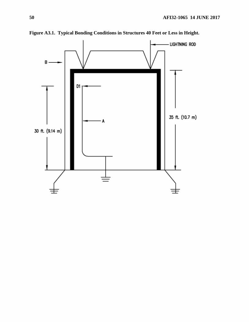
50 AFI32-1065 14 JUNE 2017
Figure A3.1. Typical Bonding Conditions in Structures 40 Feet or Less in Height.

AFI32-1065 14 JUNE 2017 51
Figure A3.2. Typical Bonding Conditions in Structures Greater Than 40 Feet in height.
[D2 cut off]
A3.4. Condition 3. Bonding of ungrounded metal bodies positioned to effectively short part of
the separation distance between a grounded metal body and a lightning conductor. In Figure
A3.3, a window is located between a grounded metal body and a lightning protection down
conductor. First, calculate the bonding distance between the grounded body and down conductor
by using the BBF according to the correct condition [2a, 2b(1), or 2b(2)]. This will provide a
distance for D. If the distance a + b is less than or equal to D, then the down conductor must be
bonded directly to the grounded metal body. Note the window itself does not have to be bonded.
Continuity tests should be performed to determine if the object is grounded, and not ungrounded,
as it may appear.
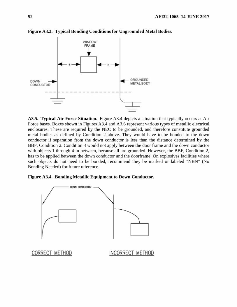
52 AFI32-1065 14 JUNE 2017
Figure A3.3. Typical Bonding Conditions for Ungrounded Metal Bodies.
A3.5. Typical Air Force Situation. Figure A3.4 depicts a situation that typically occurs at Air
Force bases. Boxes shown in Figures A3.4 and A3.6 represent various types of metallic electrical
enclosures. These are required by the NEC to be grounded, and therefore constitute grounded
metal bodies as defined by Condition 2 above. They would have to be bonded to the down
conductor if separation from the down conductor is less than the distance determined by the
BBF, Condition 2. Condition 3 would not apply between the door frame and the down conductor
with objects 1 through 4 in between, because all are grounded. However, the BBF, Condition 2,
has to be applied between the down conductor and the doorframe. On explosives facilities where
such objects do not need to be bonded, recommend they be marked or labeled "NBN" (No
Bonding Needed) for future reference.
Figure A3.4. Bonding Metallic Equipment to Down Conductor.
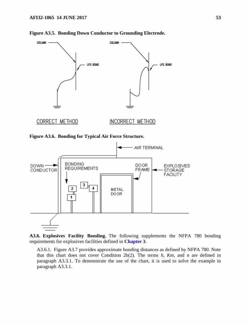
AFI32-1065 14 JUNE 2017 53
Figure A3.5. Bonding Down Conductor to Grounding Electrode.
Figure A3.6. Bonding for Typical Air Force Structure.
A3.6. Explosives Facility Bonding. The following supplements the NFPA 780 bonding
requirements for explosives facilities defined in Chapter 3.
A3.6.1. Figure A3.7 provides approximate bonding distances as defined by NFPA 780. Note
that this chart does not cover Condition 2b(2). The terms h, Km, and n are defined in
paragraph A3.3.1. To demonstrate the use of the chart, it is used to solve the example in
paragraph A3.3.1.

54 AFI32-1065 14 JUNE 2017
Figure A3.7. Sample Calculations of Bonding Distances.
D
h n = 1.0 n = 1.5 n = 2.25
ft m Km ft m ft m ft m
10 3.05 1 ft 8 in. 0.50 1 ft 13⁄8 in. 0.33 9 in. 0.22
0.5 10 in. 0.25 63⁄4 in. 0.17 41⁄2 in. 0.11
20 6.10 3 ft 4 in. 1.01 2 ft 23⁄4 in. 0.67 1 ft 6 in. 0.45
0.5 1 ft 8 in. 0.50 1 ft 13⁄8 in. 0.33 9 in. 0.22
30 9.15 5 ft 0 in. 1.52 3 ft 4 in. 1.01 2 ft 23⁄4 in. 0.67
0.5 2 ft 6 in. 0.76 1 ft 8 in. 0.50 1 ft 13⁄8 in. 0.33
40 12.2 1 6 ft 8 in. 2.03 4 ft 6 in. 1.37 3 ft 0.91
0.5 3 ft 4 in. 1.01 2 ft 3 in. 0.68 1 ft 6 in. 0.45
1. Find the height (h) (9.15 m) in the column labeled h.
2. Then select the row adjacent to the 9.15 m where Km is 0.5, since any
flashover would occur through the wall.
3. Since there is only one down conductor, n equals 1. Find the intersection of
the row selected in step 2 and the column labeled 1.0. The value in the cell is
0.76 m. Therefore, D is 0.76 m or 2 ft 6 in.
Also notice that the greatest bonding distance for objects not covered by 2b(2)
inside a facility less than 12.2 m in height is 1.01 m (3 ft 4 in).
This table derived from NFPA 780
A3.6.2. Steel magazine doors inherently in physical contact with the metallic door frame do
not need a separate bond if the resistance between the door and frame measures 1 ohm or
less. Install a bonding strap if this resistance between the door and frame measures greater
than 1 ohm. The frame must be inherently grounded through the rebar or bonded to a down
conductor.
A3.6.3. Objects such as metal desks, metal lockers, large metal trash cans, and ground-level
floor grates do not need to be bonded unless they are located within side flash distance of a
component of the lightning protection system or a static bus bar.

AFI32-1065 14 JUNE 2017 55
A3.6.4. Fence posts and railroad tracks within 6 feet (1.83 meters) of any component of a
structure’s lightning protection system must be bonded either to the structure’s grounding
system or to a ground rod which is bonded to the structure’s grounding system. In addition,
fence posts at gates where either personnel or explosives equipment may pass must be
grounded. These are test points.
A3.6.5. Blast valves must be inherently grounded through the rebar system or with a
separate bonding strap.
A3.6.6. Metal bodies located within a steel-framed structure that are inherently bonded to
the structure through construction must be tested when the facility is new and the
measurements recorded and kept with the other required measurements and observations.
They do not need to be tested again unless there is reason to believe the bond has changed,
e.g., corrosion or structural repair.
A3.7. Protective Aircraft Shelters (PAS). In PASs with interior steel arches, all grounded
metal bodies within 1 foot (0.305 meter) of the steel arch must be bonded to the arch. In PASs
without a steel arch, all grounded metal masses within 1 foot (0.305 meter) of a wall must be
bonded to the nearest metallic electrical conduit if not already connected. Only those grounded
metal bodies not inherently bonded (through metallic conduit or equipment grounding
conductor) must be tested for continuity to the ground or conduit system. All metal doors must
be grounded. Door hinges and door tracks are acceptable as a bonding strap if the doorframe or
door track is grounded and there is less than 1 ohm between the door and ground. Additional
requirements for PASs with WS3 vaults are as follows:
A3.7.1. Continuity between the steel arch and grounding system may be measured by
validating with an ohmmeter the continuity between the steel arch and any metallic electrical
conduit. Two test points between different conduits and the arch are sufficient if the test
points are spaced on opposite walls and the conduit long. This is to ensure electrical
continuity through the structural shell. If a maximum of 1 ohm is not achieved, a bonding
strap must be installed.
A3.7.2. When testing continuity between the WS3 vault and steel arch, an acceptable test
location is the vault lip or flange flush with the shelter floor. The vault does not have to be
raised. Where there is no steel arch, test from a metallic electrical conduit on the PAS wall to
the vault lip.

56 AFI32-1065 14 JUNE 2017
Attachment 4
LIGHTNING PROTECTION SYSTEMS
A4.1. Minimum Requirements. Engineers assigned specific responsibilities for lightning
protection must review the lightning protection system on each facility at least annually or after
repair actions have been completed. (T-0).
A4.1.1. Air terminals must extend at least 10 inches (0.25 meter) above the object to be
protected. (T-0). Consider the use of blunt-tipped air terminals for new system installations
on Air Force installations. (T-0). Note: When replacing air terminals with terminals of a
different length, required spacing around the perimeter must be reconfirmed and the zone of
protection verified. Figure 4.8.2.4(b) 1:1 zone of protection in NFPA 780 should extend
from the tip of the air terminal instead of the eave.
A4.1.2. Each air terminal mounted separately from the facility (non-integral system) (except
as exempted in NFPA 780) must have at least two paths to ground. (T-0). For a catenary
system consisting of non-metallic poles or masts, the second path may be one of the cross
conductors to the next pole or mast. For a metallic mast, the base must be bonded to two
separate grounding electrodes, as far apart as possible (opposite sides of the mast is the goal).
Note that for earth-covered igloos, these paths may be covered with soil.
A4.1.3. Each building with an integral protection system must have a minimum of two down
conductors, one each at opposite corners (one each on all corners is preferred). (T-0). This
provides two paths to ground. Because of the potential for galvanic corrosion, use only
aluminum lightning system conductors on metal roofs. (T-2).
A4.1.4. Down conductor design and installation must present the least possible impedance to
ground. (T-0).
A4.1.5. Down conductors must not have sharp bends or loops. All bends must have a radius
of bend not less than 8 inches (0.203 millimeters) and must measure not less than 90 degrees
from the inside of the bend. (T-0). The 8-inch (203-millimeter) radius does not apply to "T"
or "Y" splices. These splices, however, can be used only for the purpose intended.
A4.1.6. If the structure has metallic columns, these columns may serve as down conductors
as long as columns do not average more than a 60-foot (18.3-meter) separation distance.
Inherent bonding via continuity measurements must be shown on as-built drawings for new
facilities. (T-0). If not shown at the time of construction, access points for testing must be
provided and validated prior to project acceptance. (T-0).
A4.1.7. Structures must have at least two down conductors, separated as widely as
practicable. (T-0). Diagonally opposite corner locations achieve this easily. Structures
exceeding 250 feet (76 meters) in perimeter shall have a down conductor for every 100 feet
(30.5 meters) of perimeter or fraction thereof. (T-0).
A4.1.8. Any down conductors subject to mechanical damage or displacement must be
protected with a protective molding or covering for a minimum of 6 feet (1.83 meters) above
grade. (T-0). If a down conductor runs through a ferrous metal tube or pipe (usually for
mechanical protection), the conductor must be bonded to both ends of the tube or pipe (at
point of entry and exit). (T-0).
AFI32-1065 14 JUNE 2017 57
A4.1.9. LPS components must not be painted, especially down conductor connectors. (T-0).
Conductors on roofs must be bare. Oil-based paints may result in fires where lightning
impacts. Painting surfaces alter impedance characteristics. Painting contractors shall be made
aware of this requirement.
A4.1.10. Each down conductor must be connected, at its base, to a grounding electrode or to
a ground loop conductor, keeping in mind the bending restrictions of the down conductor.
(T-0).
A4.1.11. Grounding electrodes must be at least 10 ft. (3.05 m) long and made of not less
than 0.75-inch (19.05-millimeter) diameter pipe or equivalent solid rod made of copper or
copper-clad steel. (T-0). Stainless-steel grounding electrodes must not be used. Grounding
electrodes must be at least 3 feet (0.91 meters) from the building walls or footings and must
penetrate at least 10 feet (3.05 meters) into soil. (T-0). Grounding electrodes with tops at
least 1 foot (0.31 meter) below grade are recommended for mechanical protection. If
conductors are not exothermically welded to the grounding electrode, test wells are required
for new construction. (T-0).
A4.1.12. The location of new down conductors on the exterior of a structure should take into
consideration interior wall-mounted objects and be adjusted to avoid them. If avoidance is
not optional or for existing facilities, interior metal parts of a facility close to a down
conductor will need to be bonded to that down conductor if within the calculated side flash
distance. (T-0).
A4.1.13. Bonding materials must be compatible with the metallic mass and down conductor.
(T-0).
A4.1.14. On new facilities, down conductors entering soil with less than 10,000 ohm-cm
resistivity must be protected against corrosion by a protective covering beginning 6 feet (1.83
meters) above finished grade. (T-0).
A4.1.15. Adhesive fasteners for down conductors and cross conductors of an integral system
are not allowed on Air Force facilities due to the short adherence life of the adhesive.
A4.1.16. A ground loop conductor (ground ring) encircling the building must be at least 1.5
feet (0.46 meters) deep, be at least 20 feet (6.1 meters) long and be a main-size conductor,
sized from NFPA 780, Table 4.1.1.1.1 or 4.1.1.1.2) (T-0).
A4.2. Mast and Overhead Wire Systems.
A4.2.1. A mast-type lightning protection system uses masts located remote from the facility.
The mast must be high enough to enclose the facility in the zone of protection defined by
NFPA 780. (T-0). Separate each mast from any part of the facility by at least the bonding
distance specified in paragraph 4.6.5 of NFPA 780, but not less than 6 feet (1.83 meters). (T-
0). Refer to Figure A4.1.
A4.2.2. If a single mast will not protect a facility, install multiple masts or an overhead wire
system. An overhead wire or catenary system consists of grounded, elevated, horizontal
metallic wires stretched between masts surrounding the facility. Each wire must be a
continuous run of at least AWG No. 6 copper or equivalent. (T-0). Suspend each wire above
the protected facility and connect them to grounding electrodes at each mast or pole.
Interconnect all grounding electrodes with a ground loop conductor. NFPA 780, paragraphs

58 AFI32-1065 14 JUNE 2017
4.16.2.5 and 4.16.2.6, specify the minimum separation between the overhead wire and the
protected facility, which must be at least equal to the bonding distance or side flash distance.
(T-0). A minimum of 6 feet (1.83 meters) is recommended. Supporting masts must be
separated by the side flash distance, but no less than 6 feet (1.83 meters). (T-0).
Figure A4.1. Air Terminals on Masts (Typical).
A4.2.3. An air terminal extending above the top of the pole must be securely mounted to the
top of the wooden mast and connected to the grounding system. (T-0). An overhead ground
wire or a down conductor, extending above or across the top of the pole, may serve as the air
terminal if this wire or conductor is the topmost item on the mast. Each nonmetallic mast
must provide two paths to ground. A lone nonmetallic mast must have two down conductors.
Metallic masts do not require air terminals and down conductors, but must have two
connections to the grounding system or to two grounding electrodes. (T-0).

AFI32-1065 14 JUNE 2017 59
Attachment 5
MAINTENANCE SELF-CHECK FOR EXPLOSIVES FACILITIES
A5.1. Has each facility been inspected to determine the type of protection system installed? Is
the system mounted on the facility (integral) or separately mounted (mast or overhead system)?
A5.2. Are maintenance personnel familiar with lightning protection systems? See paragraph 6
for personnel qualifications and training requirements.
A5.3. Are all maintenance personnel who are qualified to perform tests or inspections familiar
with this instruction? Are all contractors or architect/engineers for large contracts within the
explosives area familiar with this instruction?
A5.4. Do all contracts and projects (even if non-LPS) on facilities with LPS require
certification/recertification of the LPS and as-builts (if construction changes are made), prior to
acceptance and payment of the last 25 percent of the contract to the contractor (this includes
SABER contracts)? This will ensure compliance with this instruction for new facilities and will
ensure that no deficiencies have been introduced onto the existing LPS of existing facilities by a
non-LPS contract.
A5.5. Are static grounding systems installed as separate subsystems? Are they connected only to
a lightning protection system down conductor (when within side flash distance) or to a ground
loop conductor? Are contact points free of corrosion, paint, grease, oil, or other agents that
prevent good bonding? Are static bus bars bonded to the single point facility ground at each end?
Note: If interior static bus bars cross an exterior down conductor within calculated side flash
distance, relocate the down conductor or the static bus bar to avoid this crossing. See paragraph
13.2 of this instruction.
A5.6. Are both the user and maintenance personnel aware of all facilities that have been
identified as housing, or being used to conduct, hazardous operations? Are personnel familiar
with any special test/inspection requirements?
A5.7. Are tests/inspections accomplished at the frequencies shown in Table 1 of this instruction?
A5.8. Are tests conducted with test instruments designed for the purpose used?
A5.9. Are personnel conducting tests familiar with the location and designation of test points
and the relationship between various components of the system prior to testing?
A5.10. Are visual inspections being performed in accordance with Table 1 of this instruction?
A5.11. Are repair actions performed when reported?
A5.12. After repair actions have been completed, are electrical tests accomplished and
documented, to ensure system integrity and records accuracy?
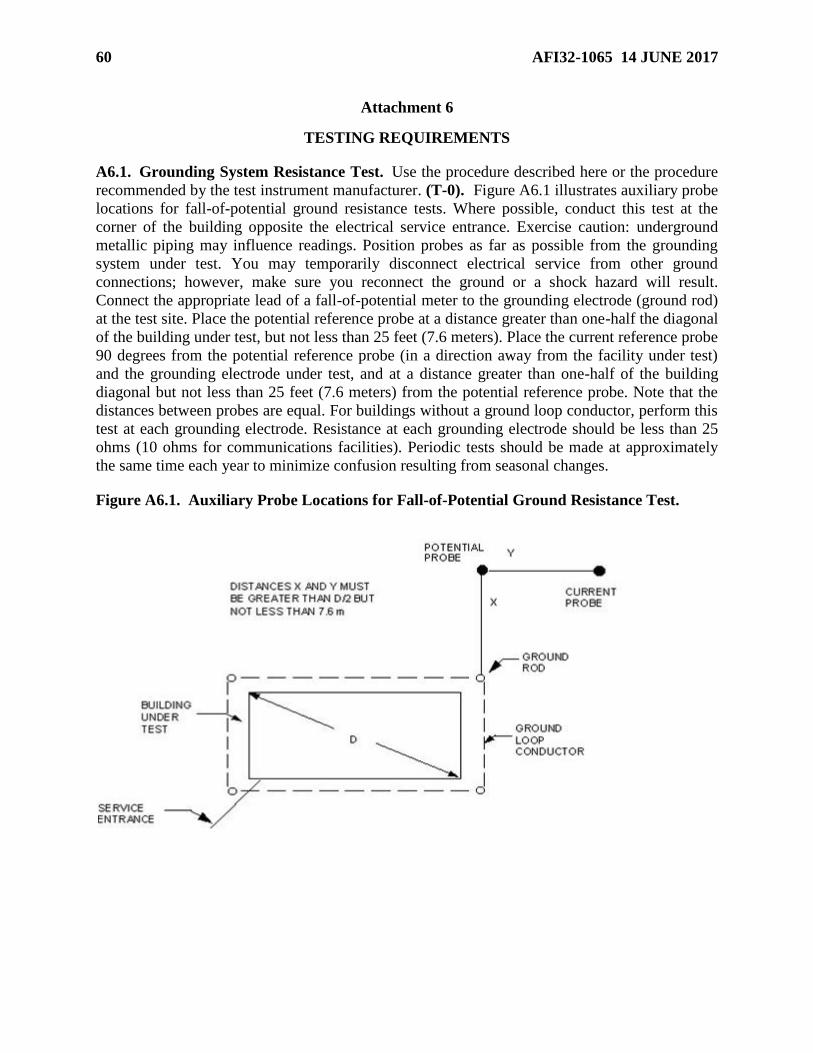
60 AFI32-1065 14 JUNE 2017
Attachment 6
TESTING REQUIREMENTS
A6.1. Grounding System Resistance Test. Use the procedure described here or the procedure
recommended by the test instrument manufacturer. (T-0). Figure A6.1 illustrates auxiliary probe
locations for fall-of-potential ground resistance tests. Where possible, conduct this test at the
corner of the building opposite the electrical service entrance. Exercise caution: underground
metallic piping may influence readings. Position probes as far as possible from the grounding
system under test. You may temporarily disconnect electrical service from other ground
connections; however, make sure you reconnect the ground or a shock hazard will result.
Connect the appropriate lead of a fall-of-potential meter to the grounding electrode (ground rod)
at the test site. Place the potential reference probe at a distance greater than one-half the diagonal
of the building under test, but not less than 25 feet (7.6 meters). Place the current reference probe
90 degrees from the potential reference probe (in a direction away from the facility under test)
and the grounding electrode under test, and at a distance greater than one-half of the building
diagonal but not less than 25 feet (7.6 meters) from the potential reference probe. Note that the
distances between probes are equal. For buildings without a ground loop conductor, perform this
test at each grounding electrode. Resistance at each grounding electrode should be less than 25
ohms (10 ohms for communications facilities). Periodic tests should be made at approximately
the same time each year to minimize confusion resulting from seasonal changes.
Figure A6.1. Auxiliary Probe Locations for Fall-of-Potential Ground Resistance Test.

AFI32-1065 14 JUNE 2017 61
A6.2. Resistance Test for Above-Ground Petroleum (POL) Tanks. Note: Before any testing
is performed for POL systems and tanks, the tester shall be familiar with the containment
systems, their locations, and their configurations to avoid puncture and compromise of the
containment system. If records of these containment system layouts are not contained in record
drawings, they shall be located and defined and included in record drawings. The method
described in paragraph A6.1 is appropriate for medium to small grounding systems. Figure A6.2
illustrates a method to measure resistance to earth of larger, more complex systems such as a
large POL tank or a substation. In areas where the soil resistivity is relatively high, a higher
voltage supply may be necessary. Local cathodic protection technicians can usually furnish the
material for the test. Make sure the tank is isolated from the utility systems by dielectric flanges.
Also be sure the cathodic protection systems are disconnected.
Figure A6.2. Measuring Resistance to Earth of Large POL Tank.
A6.2.1. Install a temporary ground bed of three or four 5-foot (1.52-meter) grounding
electrodes at a distance equal to five tank diameters. Place a copper-copper sulfate half-cell
on the opposite side of the tank. Place it at a distance equal to five tank diameters and along
an imaginary straight line through the center of the tank. Make sure it has good contact with
earth.
A6.2.2. Between the temporary ground bed and tank, install a 12-volt common vehicle
battery and a dc ammeter (multimeter with 1-amp scale may be used). Install a high-
impedance (10 megaohm or greater) dc voltmeter with a 1-volt scale between the half cell
and tank.
A6.2.3. With the battery disconnected, record the voltage reading at the voltmeter.
A6.2.4. Connect the battery and record the current at the ammeter and voltage at the
voltmeter. Read voltage immediately after connecting the battery. Current output must be
sufficient to effect a minimum 0.05 volt potential shift in the half cell reading.
A6.2.5. Calculate resistance of the tank to earth in ohms by dividing the potential change in
volts, DV, by the current in amps, or R = DV/I. For large tanks, typical values would be
A6.2.5. Calculate resistance of the tank to earth in ohms by dividing the potential change in
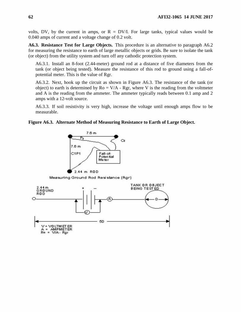
62 AFI32-1065 14 JUNE 2017
volts, DV, by the current in amps, or R = DV/I. For large tanks, typical values would be
0.040 amps of current and a voltage change of 0.2 volt.
A6.3. Resistance Test for Large Objects. This procedure is an alternative to paragraph A6.2
for measuring the resistance to earth of large metallic objects or grids. Be sure to isolate the tank
(or object) from the utility system and turn off any cathodic protection system.
A6.3.1. Install an 8-foot (2.44-meter) ground rod at a distance of five diameters from the
tank (or object being tested). Measure the resistance of this rod to ground using a fall-of-
potential meter. This is the value of Rgr.
A6.3.2. Next, hook up the circuit as shown in Figure A6.3. The resistance of the tank (or
object) to earth is determined by Ro = V/A - Rgr, where V is the reading from the voltmeter
and A is the reading from the ammeter. The ammeter typically reads between 0.1 amp and 2
amps with a 12-volt source.
A6.3.3. If soil resistivity is very high, increase the voltage until enough amps flow to be
measurable.
Figure A6.3. Alternate Method of Measuring Resistance to Earth of Large Object.

AFI32-1065 14 JUNE 2017 63
A6.4. Continuity Test/Check for Separately Mounted Lightning Protection System (Mast
and Overhead Shield Wire).
A6.4.1. To test the continuity of a mast (Figure A6.4(a)), connect one lead of an ohmmeter
to the top of the pole. Connect the other lead to the point where the conductor connects to the
ground system at ground level. If the resistance is greater than 1 ohm, check for deficiencies
and repair. For mast systems where the masts are metallic, seamless construction of a height
to provide adequate protection, the continuity test can be conducted from the base of the
mast. Masts which are of a height requiring multiple segments shall be assumed to be
seamless if, at installation, a continuity check across the slip-fit joint validates inherent
bonding by measuring 1 ohm or less across this joint. Field work which invalidates the
manufacturer’s warranty is not allowed. Initial continuity check across this joint at the time
of installation shall be recorded in test records. It shall also be noted that, based on the initial
continuity check, the joints are inherently bonded.
A6.4.2. For an overhead wire, or catenary, system (Figure A6.4(b)), visually inspect
overhead shield wires with binoculars. If the system contains mechanical connectors, a
continuity test must be conducted from the overhead shield wire to the point where the
conductor connects to the lightning protection ground system. This also applies to guy wires
when guy wires are used as a path to ground (used as a down conductor). If the resistance is
greater than 1 ohm, check for deficiencies and repair. For systems which use only exothermic
welds or high compression crimps, a visual inspection may be used to verify overhead wire
and down conductor continuity. The visual inspection may be conducted from ground level
using binoculars.
Figure A6.4. Mast System (a) and Overhead Wire or Catenary System (b).
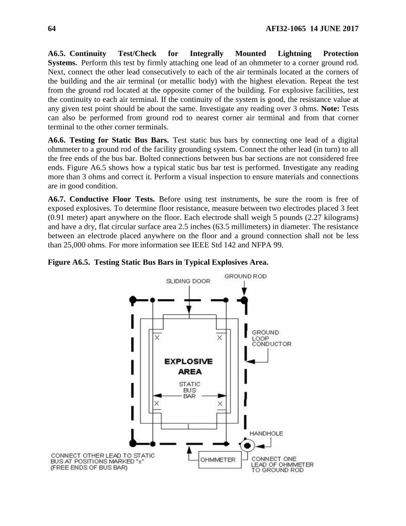
64 AFI32-1065 14 JUNE 2017
A6.5. Continuity Test/Check for Integrally Mounted Lightning Protection
Systems. Perform this test by firmly attaching one lead of an ohmmeter to a corner ground rod.
Next, connect the other lead consecutively to each of the air terminals located at the corners of
the building and the air terminal (or metallic body) with the highest elevation. Repeat the test
from the ground rod located at the opposite corner of the building. For explosive facilities, test
the continuity to each air terminal. If the continuity of the system is good, the resistance value at
any given test point should be about the same. Investigate any reading over 3 ohms. Note: Tests
can also be performed from ground rod to nearest corner air terminal and from that corner
terminal to the other corner terminals.
A6.6. Testing for Static Bus Bars. Test static bus bars by connecting one lead of a digital
ohmmeter to a ground rod of the facility grounding system. Connect the other lead (in turn) to all
the free ends of the bus bar. Bolted connections between bus bar sections are not considered free
ends. Figure A6.5 shows how a typical static bus bar test is performed. Investigate any reading
more than 3 ohms and correct it. Perform a visual inspection to ensure materials and connections
are in good condition.
A6.7. Conductive Floor Tests. Before using test instruments, be sure the room is free of
exposed explosives. To determine floor resistance, measure between two electrodes placed 3 feet
(0.91 meter) apart anywhere on the floor. Each electrode shall weigh 5 pounds (2.27 kilograms)
and have a dry, flat circular surface area 2.5 inches (63.5 millimeters) in diameter. The resistance
between an electrode placed anywhere on the floor and a ground connection shall not be less
than 25,000 ohms. For more information see IEEE Std 142 and NFPA 99.
Figure A6.5. Testing Static Bus Bars in Typical Explosives Area.

AFI32-1065 14 JUNE 2017 65
Figure A6.6. Sample Visual Inspection Form.
XX Civil Engineer Squadron Visual Inspection of Lightning Protection and Grounding
System. (For visual inspections only, fill out the first half of the form. There will be no
resistance readings unless follow-up test is required from a previous poor reading or if
repair is necessary at a test point. Document the retest and repairs in “Discrepancies or
Test Notes” below.)
Building XXXX
Date of
Inspection: xx/xxxx/xx
Inspection
Performed By:
Inspector’s
Initials
Yes No Visual Inspection of Lightning Protection System
Is the lightning protection system in good repair? IAW AFI 32-1065, Section B, para. 9.1, and NFPA 780,
Annex D, para. D.1.2 (1)
Are there loose connections that might cause high-resistance joints? IAW AFI 32-1065, Section B, para.
9.2, and NFPA 780, Annex D, para. D.1.2 (2)
Has corrosion or vibration weakened any part of the lightning protection system? IAW AFI 32-1065,
Section B, para. 9.3, and NFPA 780, Annex D, para. D.1.2 (3)
Are down conductors, roof conductors, and ground terminals intact? IAW AFI 32-1065, Section B, para.
9.4, and NFPA 780, Annex D, para. D.1.2 (4)
Are braided bonding wires excessively frayed? (cross-sectional area reduced by half) IAW AFI 32-1065,
Section B, para. 9.5
Are ground wires on the lightning protection masts damaged by lawn mowers or other equipment? IAW
AFI 32-1065, Section B, para. 9.6
Are conductors and system components securely fastened to mounting surfaces? IAW AFI 32-1065,
Section B, para. 9.7, and NFPA 780, Annex D, para. D.1.2 (5)
Have additions or alterations to the protected structure required additional protection? IAW AFI 32-
1065, Section B, para. 9.8, and NFPA 780, Annex D, para. D.1.2 (6)
Do surge suppression (over voltage) devices appear damaged? IAW AFI 32-1065, Section B, para. 9.9, and
NFPA 780, Annex D, para. D.1.2 (7)
Does the lightning protection system comply with applicable sections of NFPA 780 and AFI 32-1065? IAW AFI 32-1065, Section B, para. 9.10, and NFPA 780, Annex D, para. D.1.2 (8)
Is there a counterpoise grounding system Test well ground resistance reading Ω
Soil condition on date of Inspection Ambient Temp °F
Test reel resistance reading Ω
Continuity test from test well to static ground system / minus the test reel resistance
Test
Point
Resistance
Reading
Test
Point
Resistance
Reading
Test
Point
Resistance
Reading
Test
Point
Resistance
Reading
Test
Point
Resistance
Reading
Test
Point
Resistance
Reading
1 Ω 15 Ω 29 Ω 43 Ω 57 Ω 71 Ω
2 Ω 16 Ω 30 Ω 44 Ω 58 Ω 72 Ω
3 Ω 17 Ω 31 Ω 45 Ω 59 Ω 73 Ω
4 Ω 18 Ω 32 Ω 46 Ω 60 Ω 74 Ω
5 Ω 19 Ω 33 Ω 47 Ω 61 Ω 75 Ω
6 Ω 20 Ω 34 Ω 48 Ω 62 Ω 76 Ω
7 Ω 21 Ω 35 Ω 49 Ω 63 Ω 77 Ω
8 Ω 22 Ω 36 Ω 50 Ω 64 Ω 78 Ω
9 Ω 23 Ω 37 Ω 51 Ω 65 Ω 79 Ω
10 Ω 24 Ω 38 Ω 52 Ω 66 Ω 80 Ω
11 Ω 25 Ω 39 Ω 53 Ω 67 Ω
12 Ω 26 Ω 40 Ω 54 Ω 68 Ω
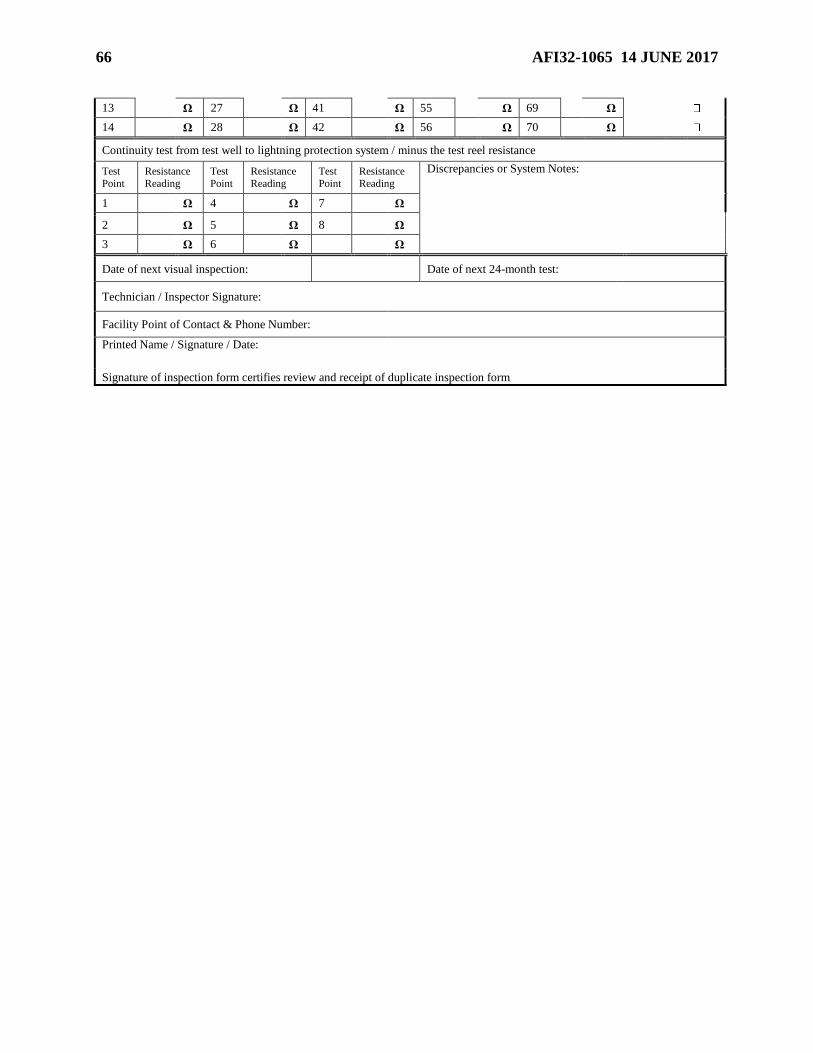
66 AFI32-1065 14 JUNE 2017
13 Ω 27 Ω 41 Ω 55 Ω 69 Ω
14 Ω 28 Ω 42 Ω 56 Ω 70 Ω
Continuity test from test well to lightning protection system / minus the test reel resistance
Test
Point
Resistance
Reading
Test
Point
Resistance
Reading
Test
Point
Resistance
Reading
Discrepancies or System Notes:
1 Ω 4 Ω 7 Ω
2 Ω 5 Ω 8 Ω
3 Ω 6 Ω Ω
Date of next visual inspection: Date of next 24-month test:
Technician / Inspector Signature:
Facility Point of Contact & Phone Number:
Printed Name / Signature / Date:
Signature of inspection form certifies review and receipt of duplicate inspection form

AFI32-1065 14 JUNE 2017 67
Figure A6.7. Sample 24-Month Resistance/Continuity Test/Visual Inspection of LPS and
Grounding System.
XX Civil Engineer Squadron 24-Month Resistance/Continuity Test and Visual Inspection
of Lightning Protection and Grounding System
Building XXXX
Date of
Tests/Inspec
tion:
xx/xxxx/xx Tests/Inspection
Performed By:
Technician/
Inspector
Initials
Yes No Visual Inspection of Lightning Protection System
Is the lightning protection system in good repair? IAW AFI 32-1065, Section B, para. 9.1, and NFPA 780,
Annex D, para. D.1.2 (1)
Are there loose connections that might cause high-resistance joints? IAW AFI 32-1065, Section B, para.
9.2, and NFPA 780, Annex D, para. D.1.2 (2)
Has corrosion or vibration weakened any part of the lightning protection system? IAW AFI 32-1065,
Section B, para. 9.3, and NFPA 780, Annex D, para. D.1.2 (3)
Are down conductors, roof conductors, and ground terminals intact? IAW AFI 32-1065, Section B, para.
9.4, and NFPA 780, Annex D, para. D.1.2 (4)
Are braided bonding wires excessively frayed? (cross-sectional area reduced by half) IAW AFI 32-1065,
Section B, para. 9.5
Are ground wires on the lightning protection masts damaged by lawn mowers or other equipment? IAW
AFI 32-1065, Section B, para. 9.6
Are conductors and system components securely fastened to mounting surfaces? IAW AFI 32-1065,
Section B, para. 9.7, and NFPA 780, Annex D, para. D.1.2 (5)
Have additions or alterations to the protected structure required additional protection? IAW AFI 32-
1065, Section B, para. 9.8, and NFPA 780, Annex D, para. D.1.2 (6)
Do surge suppression (over voltage) devices appear damaged? IAW AFI 32-1065, Section B, para. 9.9, and
NFPA 780, Annex D, para. D.1.2 (7)
Does the lightning protection system comply with applicable sections of NFPA 780 and AFI 32-1065? IAW AFI 32-1065, Section B, para. 9.10, and NFPA 780, Annex D, para. D.1.2 (8)
Is there a counterpoise grounding system Test well ground resistance reading Ω
Soil condition on date of Inspection Ambient Temp °F
Test reel resistance reading Ω
Continuity test from test well to static ground system / minus the test reel resistance
Test
Point
Resistance
Reading
Test
Point
Resistance
Reading
Test
Point
Resistance
Reading
Test
Point
Resistance
Reading
Test
Point
Resistance
Reading
Test
Point
Resistance
Reading
1 Ω 15 Ω 29 Ω 43 Ω 57 Ω 71 Ω
2 Ω 16 Ω 30 Ω 44 Ω 58 Ω 72 Ω
3 Ω 17 Ω 31 Ω 45 Ω 59 Ω 73 Ω
4 Ω 18 Ω 32 Ω 46 Ω 60 Ω 74 Ω
5 Ω 19 Ω 33 Ω 47 Ω 61 Ω 75 Ω
6 Ω 20 Ω 34 Ω 48 Ω 62 Ω 76 Ω
7 Ω 21 Ω 35 Ω 49 Ω 63 Ω 77 Ω
8 Ω 22 Ω 36 Ω 50 Ω 64 Ω 78 Ω
9 Ω 23 Ω 37 Ω 51 Ω 65 Ω 79 Ω
10 Ω 24 Ω 38 Ω 52 Ω 66 Ω 80 Ω
11 Ω 25 Ω 39 Ω 53 Ω 67 Ω
12 Ω 26 Ω 40 Ω 54 Ω 68 Ω
13 Ω 27 Ω 41 Ω 55 Ω 69 Ω

68 AFI32-1065 14 JUNE 2017
14 Ω 28 Ω 42 Ω 56 Ω 70 Ω
Continuity test from test well to lightning protection system / minus the test reel resistance
Test
Point
Resistance
Reading
Test
Point
Resistance
Reading
Test
Point
Resistance
Reading
Discrepancies or System Notes:
1 Ω 4 Ω 7 Ω
2 Ω 5 Ω 8 Ω
3 Ω 6 Ω Ω
Date of next visual inspection: Date of next 24-month test):
Technician / Inspector Signature:
Facility Point of Contact & Phone Number:
Printed Name / Signature / Date:
Signature of inspection form certifies review and receipt of duplicate inspection form
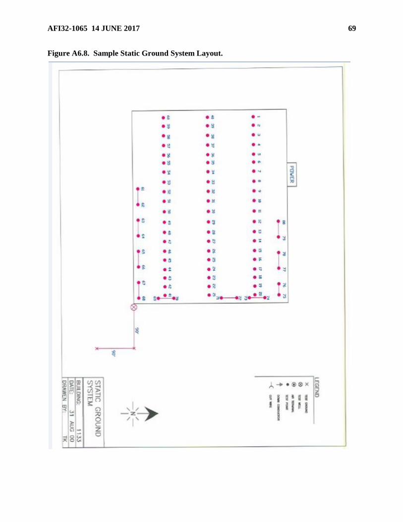
AFI32-1065 14 JUNE 2017 69
Figure A6.8. Sample Static Ground System Layout.

70 AFI32-1065 14 JUNE 2017
Figure A6.9. Sample Layout of Points for Catenary System.
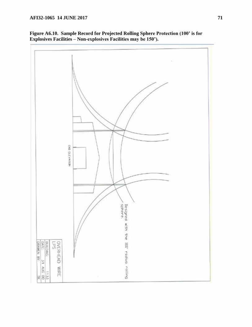
AFI32-1065 14 JUNE 2017 71
Figure A6.10. Sample Record for Projected Rolling Sphere Protection (100’ is for
Explosives Facilities – Non-explosives Facilities may be 150’).