bus module profinet - advanced energyethernet bus module profinet order-no. 2000 000 846. 7 1.4...
TRANSCRIPT

1
BUS MODULE PROFINET FOR ThyRO-S, ThyRO-A, ThyRO-AX, ThyRO-POwER MANAgER,
ThyRO-STEP CONTROLLER, ThyRO-MEASUREMENT UNIT,
ThyRO-A ...C01, ...C02, ...C03, ...C05 AND ...C07
July 2014 DE/EN - V3
2
1. Introduction 6
1.1 general 6
1.2 Special features 6
1.3 Type designation 6
1.4 Abbreviations 6
1.5 warranty 7
2. Safety 8
2.1 Identification in the operating instructions 8
2.2 general danger information 9
2.3 Operator requirements 10
2.4 Personnel requirements 10
2.5 Intended use 10
2.6 Use of the device 11
2.6.1 Operation 11
2.6.2 Prior to installation/commissioning 11
2.6.3 Maintenance, service, faults 11
2.6.4 Transport 12
3. Functions 13
3.1 Processing the setpoint Thyro-S 13
3.2 Processing the setpoint Thyro-A/Thyro-AX 13
3.3 Processing the setpoint Thyro-Step Controller 14
3.4 Freely addressable digital outputs 15
4. Installation 16
4.1 Connection terminals (overview) 16
4.2 Connecting a 24 V power supply 16
4.3 Connecting the power controller to X1-X8 17
4.4 Connecting the Ethernet bus module to the master 17
5. Settings 18
5.1 Setting the protocol 18
CONTENTS
3
5.2 Setting the number of slots 18
5.3 Setting the device name 18
5.4 Operating display of the bus module 20
6. Operation 21
6.1 Start configuration (parameterization) 21
6.2 Cyclical data transmission (configuration) 22
6.3 Input and output data Thyro-S 22
6.4 Input and output data Thyro-A/Thyro-AX 24
6.5 Input and output data Thyro-Power Manager 35
6.6 Input and output data Thyro-Step Controller 36
6.7 Input and output data Thyro Input/Output Unit 37
6.8 Input and output data Thyro- Measurerment Unit 38
6.9 Acyclic data transmission (parameterization) 39
7. External connections 41
7.1 Power supply 41
7.2 Operating elements and terminal blocks 42
8. Interfaces 43
8.1 System interface 43
8.2 Ethernet interface 43
9. Connection diagrams Thyro-A/Thyro-AX 44
10. Connection diagrams Thyro-S 45
11. Connection diagrams Thyro-Step Controller 46
12. Specific notes 47
12.1 Installation 47
12.2 Service 47
13. Technical Data 47
14. Dimension drawings 48
15. Accessories and options 48
16. Approvals and conformity 49
17. Appendix A Acyclic parameter tables 50
4
Fig. 1 Configuration & LED dis plays 19
Fig. 2 Connection diagram Thyro-A/Thyro-AX 44
Fig. 3 Connection diagram Thyro-S 45
Fig. 4 Connection diagram TSC 46
Tab. 1 Connecting terminals (overview) 16
Tab. 2 Operating display of the bus module 20
Tab. 3 Interpretation of the master setpoint for Thyro-S 22
Tab. 4 Cyclic input and output data for Thyro-S…h1 22
Tab. 5 Cyclic input and output data for Thyro-S…hRL1 23
Tab. 5a Thyro-S Faults 23
Tab. 5b Thyro-S Status 24
Tab. 6 Cyclic input and output data for Thyro-A 1A…h1 24
Tab. 7 Cyclic input and output data for Thyro-A 1A...hRL1/Thyro-AX 1A...hRL2 25
Tab. 8 Cyclic input and output data for Thyro-A 1A...hRLP1/Thyro-AX 1A...hRLP2 25
Tab. 9 Cyclic input and output data for Thyro-A 2A…h1 26
Tab. 10 Cyclic input and output data for Thyro-A 2A...hRL1/Thyro-AX 2A...hRL2 26
Tab. 11 Cyclic input and output data for Thyro-A 2A...hRLP1/Thyro-AX 2A...hRLP2 27
Tab. 12 Cyclic input and output data for Thyro-A 3A…h1 27
Tab. 13 Cyclic input and output data for Thyro-A 3A...hRL1/Thyro-AX 3A...hRL2 28
Tab. 14 Cyclic input and output data for Thyro-A 3A...hRLP1/Thyro-AX 3A...hRLP2 29
Tab. 14a Thyro-A/Thyro-AX Fault 30
Tab. 14b Thyro-A/Thyro-AX Status 31
Tab. 15 Cyclic input and output data for Thyro-A 1A…C01 32
Tab. 16 Cyclic input and output data for Thyro-A 1A…C02 32
Tab. 17 Cyclic input and output data for Thyro-A 1A…C03 33
Tab. 18 Cyclic input and output data for Thyro-A 1A…C05 33
Tab. 19 Cyclic input and output data for Thyro-A 1A…C07 34
Tab. 20 Supported operating modes 34
Tab. 21 Cyclic input and output data TPM automatic mode 35
Tab. 22 Cyclic input and output data TPM manual mode 35
Tab. 23 Cyclic input and output data TSC mode 36
Tab. 24 Cyclic input and output data TIO mode 37
Tab. 25 Cyclic input and output data TMU mode 38
Tab. 25a Status TPM, TSC, TIO,TMU 38
Tab. 25b Faults TPM, TSC, TIO,TMU 39
LIST OF FIgURES AND TABLES
5
CONTACT
TEChNICAL qUERIESDo you have any technical queries regarding the subjects dealt with inthese operating instructions?If so, please get in touch with our team for power controllers:Phone +49 (0) 2902 763-520
COMMERCIAL qUERIESDo you have any commercial queries on power controllers?If so, please get in touch with our team for power controllers.Phone +49 (0) 2902 763-558
SERVICEAdvanced Energy Industries gmbhBranch Office warstein-BeleckeEmil-Siepmann-Straße 32D-59581 warsteinPhone +49 (0) 2902 763-0http://www.advanced-energy.com
COPyRIghTNo part of these operating instructions may be transmitted, reproduced and/or copied by any electronic or mechanical means without the express prior written permission of Advanced Energy.© Copyright Advanced Energy Industries gmbh 2014.All rights reserved.
FURThER INFORMATION ON COPyRIghTThyro-™, Thyro-S™, Thyro-A™, Thyro-AX™ are registered trademarks of Advan-ced Energy Industries gmbh. All other company and product names are (registered) trademarks of the respective owners.
6
1. INTRODUCTION
The operating instructions below serve only as an addition to be used in conjunction with the operating instructions of the Advanced Energy Thyro-A and Thyro-AX power controllers, Thyro-S power switch, and Thyro-Power Ma-nager in the versions of the types indicated on the covering page. The safety instructions contained therein are to be observed in particular.
1.1 gENERALThe Ethernet bus module can connect up to 8 power controllers of type Thyro-A, type Thyro-AX and type Thyro-S with a master in any desired order.Several bus modules can be used on one system.The power supply of the bus module comes from an external 24 V DC voltage source (150 mA), which is to be fed in (reverse polarity protected) at X11.1 (+) and X11.2 (ground). Several modules can be operatedfrom one power supply. As short a ground connection as possible is needed at terminal X11.3 for EMC reasons.
1.2 SPECIAL FEATURES· The Ethernet bus module connects the devices with several Ethernet bus systems. By setting the “Protocol” switch to 0, the Ethernet bus module beco-mes a PROFINET IO-device.
· when position 9 „Set all default“ is active the bus module will be reset to factory defaults for settings and address.
· when the bus module is linked to Thyro-AX, please be aware that data trans-fer is the same as for Thyro-A whereas special features or other additional parameters are excluded from this.
· function control via LED· 8 free application outputs X1 to X8 in each case terminal 5· C-rail assembly
1.3 TyPE DESIgNATIONEthernet bus module PROFINET order-no. 2000 000 846
7
1.4 ABBREVIATIONSAdvanced Energy Advanced Energy Industries gmbhTPM Thyro-Power ManagerTSC Thyro-Step ControllerTMU Thyro-Measurment UnitTIO Thyro Input/Output Unit
1.5 wARRANTyIn the event of any claims in connection with the Ethernet bus module, please contact us quoting:· type designation· fabrication number / serial number· reason for the complaint· environmental conditions of the device· operating mode· period of use
goods and services are subject to the general conditions of supply for products of the electrical industry, and our general sales conditions. Claims in connection with supplied goods must be submitted within one week of receipt, along with the delivery note. Advanced Energy will rescind all obli-gations such as warranty agreements, service contracts, etc. entered into by Advanced Energy or its representatives without prior notice if maintenance and repair work is carried out using anything other than original Advanced Energy spare parts or spare parts purchased from Advanced Energy.

8
2. SAFETy
2.1 IDENTIFICATION IN ThE OPERATINg INSTRUCTIONSIn these operating instructions, there are warnings before dangerous actions. These warnings are divided into the following danger categories:
DANgERDangers that can lead to serious injuries or fatal injuries.
wARNINgDangers that can lead to serious injuries or considerable damage to property.
CAUTIONDangers that can lead to injuries and damage to property.
CAUTIONDangers that can lead to minor damage to property.The warnings can also be supplemented with a special danger symbol (e.g. ”Electric current“ or ”hot parts“) , e.g.
risk of electric current or
risk of burns.
9
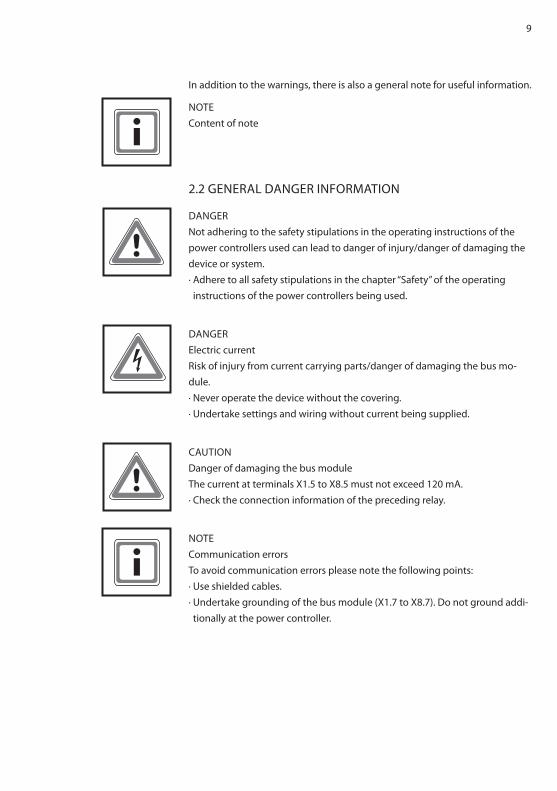
In addition to the warnings, there is also a general note for useful information.
NOTEContent of note
2.2 gENERAL DANgER INFORMATION
DANgERNot adhering to the safety stipulations in the operating instructions of the power controllers used can lead to danger of injury/danger of damaging the device or system.· Adhere to all safety stipulations in the chapter “Safety” of the operating instructions of the power controllers being used.
DANgERElectric currentRisk of injury from current carrying parts/danger of damaging the bus mo-dule.· Never operate the device without the covering.· Undertake settings and wiring without current being supplied.
CAUTIONDanger of damaging the bus moduleThe current at terminals X1.5 to X8.5 must not exceed 120 mA.· Check the connection information of the preceding relay.
NOTECommunication errorsTo avoid communication errors please note the following points:· Use shielded cables.· Undertake grounding of the bus module (X1.7 to X8.7). Do not ground addi-tionally at the power controller.
10
2.3 OPERATOR REqUIREMENTSThe operator must ensure the following:· The safety regulations of the operating instructions are observed.· The accident prevention regulations valid in the respective country of use and the general safety regulations are observed.
· All safety devices (covers, warning signs etc.) are present, in perfect condi-tion and are used correctly.
· The national and regional safety regulations are observed.· The personnel has access to the operating instructions and safety regulati-ons at all times.
· The operating conditions and restrictions resulting from the technical data are observed.
· Should abnormal voltages, noises, increased temperatures, vibration or similar occur, the device is immediately put out of operation and the mainte-nance personnel is informed.
2.4 PERSONNEL REqUIREMENTSOnly qualified electro-technical personnel who are familiar with the pertinent safety and installation regulations may perform the following:· transport· installation· connection· commissioning· maintenance· testing· operation
These operating instructions must be read carefully by all persons working with or on the equipment prior to installation and initial start-up.
2.5 INTENDED USEThe device may only be used for the purpose for which it was intended, as persons may otherwise be exposed to dangers (e.g. electric shock, burns) and plants also (e. g. overload). The user must therefore observe the following points:· It is not permitted to make any unauthorized modifications to the unit or to use any spare parts or replacement parts not approved by Advanced Energy, or to use the unit for any other purpose.
11
· The warranty obligations of the manufacturer are only applicable if these operating instructions are observed and complied with.
· The device is a component that cannot function alone.· Project planning must account for the proper use of the device.
2.6 USE OF ThE DEVICE
2.6.1 OPERATION· Only switch on the mains voltage at the device when there is no danger to persons, system or load.
· Protect the device against dust and damp.· Ensure that the ventilation openings are not blocked.
2.6.2 PRIOR TO INSTALLATION/COMMISSIONINg· If stored in a cold environment: ensure that the device is absolutely dry. (Allow the device a period of at least two hours to acclimatize before com-missioning).
· Ensure sufficient ventilation of the cabinet if mounted in a cabinet.· Observe minimum spacing.· Ensure that the device cannot be heated up by heat sources below it. (see chapter 13, Technical data).
· ground the device in accordance with local regulations.· Connect the device in accordance with the connection diagrams.
2.6.3 MAINTENANCE, SERVICE, FAULTSIn order to avoid personal and material damages, the user must observe the following:· Before all work:· Disconnect the device from all external voltage sources.· Secure the device against accidentally being switched back on.· Use suitable measuring instruments and check that there is no voltage present.
· ground and short circuit the device.· Provide protection by covers or barriers for any neighboring live parts.· The device may only be serviced and repaired by trained electro-technical personnel.

12
2.6.4 TRANSPORT· Only transport the device in the original packaging.· Protect the device against damage, caused by jolts, knocks and contaminati-on, for instance.
13
3. FUNCTIONS
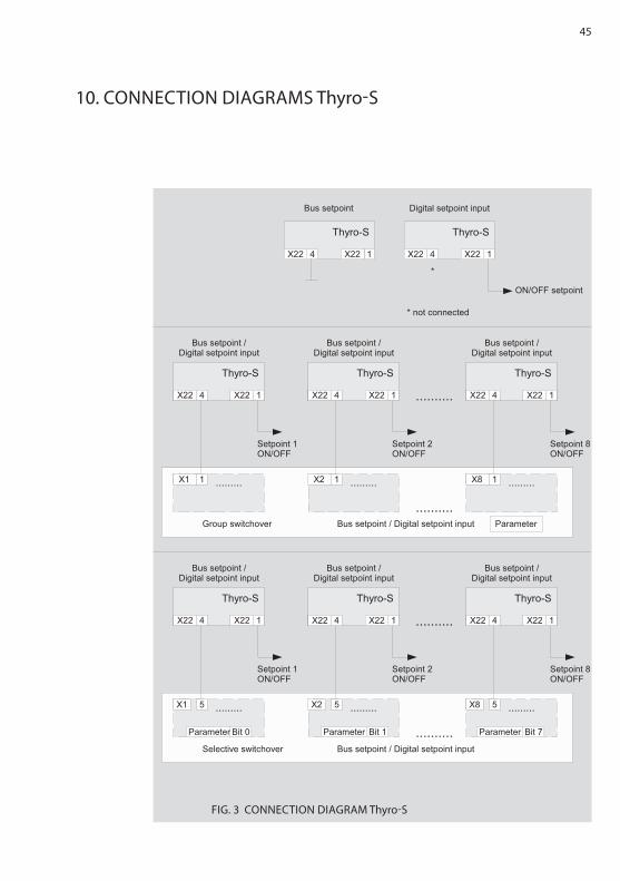
3.1 PROCESSINg ThE SETPOINT Thyro-SOnly local setpoints, no bus setpointSwitching signal (24DC) at the control terminal X22.1 of the Thyro-S· No wiring of the terminal point X22.4 at the power controller.· The bus module is fully functional. The analog signal from the control termi-nal X22.1 is used as setpoint (on/off).
Setpoint from the bus module (X22.3), no local setpoint· Connect the ground to terminal X22.4 of the power controller.· The master setpoint of the bus module is used. For this purpose the setpoint is interpreted as the operating mode.
Bus setpoint, switching over to „local“ in case of bus faultOnly use the setpoint of the bus module if there is an IO connection.· Connect terminal X22.4 of the power controller to one of the terminals X1.1 to X8.1 of the bus module.
· If there is an IO connection the master set point is used. If not then the analog signal from the control terminal X22.1 is used as setpoint (on/off).
Switching over to bus/local setpoint switchable for each controller in operationIndividual setpoint from the bus module for each power controller.· Connect terminal X22.4 of the power controller to one of the terminals X1.5 to X 8.5 of the bus module.
· The power controllers can be switched over individually (targeted) via the bus between master setpoint and terminal X22.1.
3.2 PROCESSINg ThE SETPOINT Thyro-A/Thyro-AXOnly local set points, no bus set point:Analog input at control terminal X2.4 of Thyro-A/Thyro-AX> Do not connect anything to terminal X22.1 of the power controller.- The bus module is fully functional. The analog signal from the control termi-nal X2.4 is used as set point (on/off).
Set point from the bus module (X22.3), no local set point:> Connect the ground to terminal X22.1 of the power controller.- The master set point of the bus module is used.
14
Bus set point, switching over to “local” in case of bus fault:Only use the set point of the bus module if there is an IO connection.> Connection between X22.1 Thyro-A and bus module X1.1 to X8.1During normal operation, the set point is digital.If an error is detected in the bus module or Ethernet IP communications, then the bus module will automatically float the bus module, X1.1 output.This causes the Thyro-A, X22.1 input to go high and switches to analog set point for Thyro-A (switches to 4-20mA or potentiometer control).For further details: Chapter 17. Connection diagrams Thyro-A / Thyro-AX, Fig.2
- If there is an IO connection the master set point is used. If there is no IOconnection then the analog signal from the control terminal X2.4 is used asset point.
Switching over to bus / local set point reversible for each controller in opera-tion:Individual set point from the bus module for each power controller.> Connection between X22.1 Thyro-A and bus module X1.5 to X8.5 During normal operation, the set point is analog (bit set to 0)If the bit is set to 1 then the Thyro-A set point is switched to digital.If an error is detected in the bus module or Ethernet IP communications, then the bus module will automatically float the bus module, X1.5 output.For further details: Chapter 17. Connection diagrams Thyro-A / Thyro-AX, Fig.2
- The power controllers can be switched over individually (targeted) via thebus between master set point and terminal X2.4.
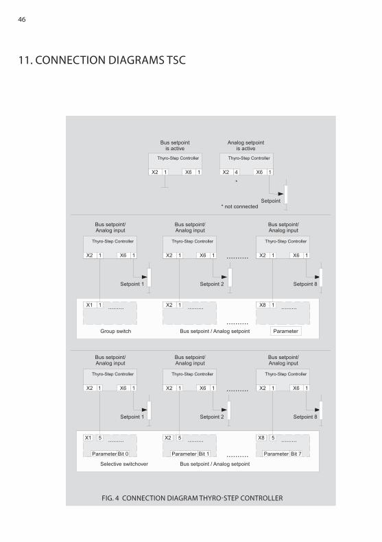
3.3 PROCESSINg ThE SETPOINT Thyro-Step ControllerOnly local setpoints, no bus setpointAnalog input at control terminal X6.1 or X6.4 (depending on X6.7) of the TSC· Do not connect anything to terminal X2.1 of the power controller.· The bus module is fully functional. The analog signal from the control termi-nal X6.1 or X6.4 is used as setpoint.
Setpoint from the bus module (X22.3), no local setpoint· Connect the ground to terminal X2.1 of the TSC.· The master setpoint of the Ethernet bus module is used.
Bus setpoint, switching over to “local” in case of bus faultOnly use the setpoint of the bus module if there is an IO connection.· Connect terminal X2.1 of the TSC to one of the terminals X1.1 to X8.1 of the bus module.
15
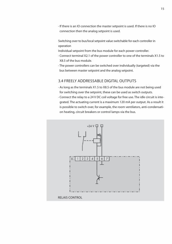
RELAIS CONTROL
· If there is an IO connection the master setpoint is used. If there is no IO connection then the analog setpoint is used.
Switching over to bus/local setpoint value switchable for each controller in operationIndividual setpoint from the bus module for each power controller.· Connect terminal X2.1 of the power controller to one of the terminals X1.5 to X8.5 of the bus module.
· The power controllers can be switched over individually (targeted) via the bus between master setpoint and the analog setpoint.
3.4 FREELy ADDRESSABLE DIgITAL OUTPUTS· As long as the terminals X1.5 to X8.5 of the bus module are not being used for switching over the setpoint, these can be used as switch outputs.
· Connect the relay to a 24 V DC coil voltage for free use. The idle circuit is inte-grated. The actuating current is a maximum 120 mA per output. As a result it is possible to switch over, for example, the room ventilators, anti-condensati-on heating, circuit breakers or control lamps via the bus.
16
4. INSTALLATION
DANgERDangers during InstallationRisk of injury/Risk of damage to the device or plantObserve all safety regulations in the chapter “Safety”.
4.1 CONNECTION TERMINALS (OVERVIEw)
TERMINAL DESCRIPTION
X11 .1 24 V (+)
.2 24 V (ground)
.3 grounding, carry out as short as possible
X1-X8 .1 jointly switchable ground potential
.2 RxD
.3 TxD
.4 ground
.5 separately switchable ground potential
.6 ground
.7 ground potential for shield connection
TAB. 1 CONNECTINg TERMINALS (OVERVIEw)
Connection diagram see page 44.
4.2 CONNECTINg A 24 V POwER SUPPLy· Switch off the main power supply including the external 24 V power source and make sure these cannot be accidentally switched back on again.
· Connect the external 24 V voltage supply (150 mA) to X11.1 (+) and X11.2 (-) (reverse polarity protection).
· ground the X11.3 terminal by as short a route as possible (for EMC reasons).

17
REMARk24 V DC power sourceSeveral bus modules can be operated with one power supply.· In cases of SELV (safety extra low voltages) do not ground the 24 V power source.
4.3 CONNECTINg ThE POwER CONTROLLER TO X1-X8· Switch off the main power supply including the external 24 V power source and make sure these cannot be accidentally switched back on again.
· Connect the interfaces X1 to X8 of the bus module to the system interfaces of the power controller (shielded four-wire cable)
Attention: To control all parameters by PROFINET we recommend closing the Thyro-A/Thyro-AX switches S1.3, S1.4, S1.5 (Thyro-Tool Mode).
4.4 CONNECTINg ThE EThERNET BUS MODULE TO ThE MASTERThe Ethernet bus module has two Ethernet ports which are equipped with a switch functionality which allows a line topology to be constructed.A standard patch cable is required for connecting with a switch. For a direct connection (line topology) a cross-over cable is required.
18
5. SETTINgS
5.1 SETTINg ThE PROTOCOLThe Ethernet bus module supports various real time Ethernet bus systems. The desired system can be selected using the rotary switch “Protocol”. For PROFINET this needs to be set to 0.
5.2 SETTINg ThE NUMBER OF SLOTSThe number of devices which are connected to the Ethernet bus module is set with the rotary switch “Slots”. After switching on, the Ethernet bus module reads all the parameters of the device. Following this it starts communicating.
Attention: To change the number of slots when switched on, the switch “Slots” must first be turned to 0. Communication with the master is then interrupted. Following this the desired number can be set. Afterleaving the position 0 you have about 2 seconds time for this.
5.3 SETTINg ThE DEVICE NAMEEvery IO device is identified by its device name. The setting of the device name can be undertaken using, for example, the program “Step 7 – hw Config” in the menu “Target system/Ethernet/Edit Ethernet participant…”
19
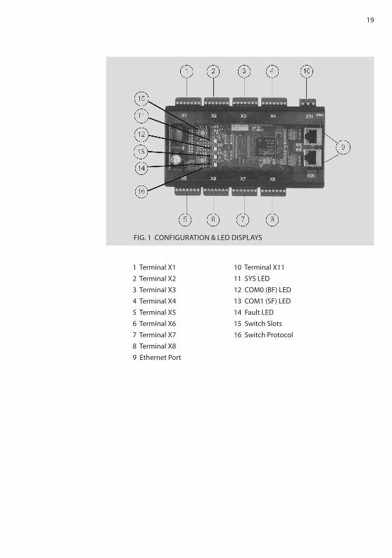
FIg. 1 CONFIgURATION & LED DISPLAyS
1 Terminal X1 10 Terminal X112 Terminal X2 11 SyS LED3 Terminal X3 12 COM0 (BF) LED4 Terminal X4 13 COM1 (SF) LED5 Terminal X5 14 Fault LED6 Terminal X6 15 Switch Slots7 Terminal X7 16 Switch Protocol8 Terminal X89 Ethernet Port
20
5.4 OPERATINg DISPLAy OF ThE BUS MODULE
LED COLOR STATUS MEANINg
SyS green On Operating system running
Red Flashing with 1 hz Error in boot process
Red On waiting for boot process (check posi-
tion of “Protocol” switch)
Off No supply voltage
COM0 (BF) Red On No physical connection
Red Flashing with 2 hz No data exchange
Off The device is exchanging data with
the PROFINET IO Controller
COM1 (SF) Red On watchdog time out or system error
Off No error
Fault Red On hardware error
TAB. 2 OPERATINg DISPLAy OF ThE BUS MODULE
OPERATINg STATUS OF ThE EThERNET BUS MODULE
LED COLOR STATUS MEANINg
Link green On There is an Ethernet connection
Activity yellow On Data are being exchanged via
Ethernet
STATUS LED OF ThE EThERNET PORTS
21
6. OPERATION
6.1 START CONFIgURATION (PARAMETERIzATION)Via the parameterization (in step 7 – hw Config, double-click on slot 0 of the bus module, parameter tab) the following settings can be undertaken.
No connection (slot 1-8):here you can set what should happen with the output data of the devices if the connection to the master is interrupted.hold last values The output data are not changed.Outputs = 0 The output data are set to 0.
No connection (slot 9):here you can set what should happen with the output data of the bus modu-le if the connection to the master is interrupted.hold last value The digital outputs are not changed.Outputs = 0 The digital outputs are set to 0.
Averaging of the measured values:here you can enter the number of actual values which flow into the ave-raging. A new value is calculated once a second. Values from 0-20 can be entered, whereby 0 or 1 deactivates this function.
Remove device when it is switched off:Not all devices are equipped with a 24 V supply connection. when switching off the Thyro mains supply and the control voltage supply (24 V) the Thyro no longer communicates with the bus modules. A switched off device will normally be displayed as pull. This display can be suppressed here.Deactivate Devices which are no longer accessible (no commu-
nication) will continue to be displayed as plug.Activate Devices which are no longer accessible will be
displayed as pull.
22
Use output data:The suppression of certain output data can be activated here.Always New output data are transferred immediately.Only when Bit is set New output data are only transferred, if the Bit
0 is set in the output “Functions”.ATTENTION If the setting of Thyro-A / Thyro-AX are changed with Thyro-Tool Family, then the new values are not automatically implemented into the bus module. To save the values permanently, the switch „slot“ shoudl be turned very shortly to 0 and back to its original position. Then the values are saved in the bus module.
6.2 CyCLICAL DATA TRANSMISSION (CONFIgURATION)The configuration of the cyclical data traffic is undertaken by adding modu-les.The input and output data depend on the device types. The following tables show the input and output data available for each of the devices.
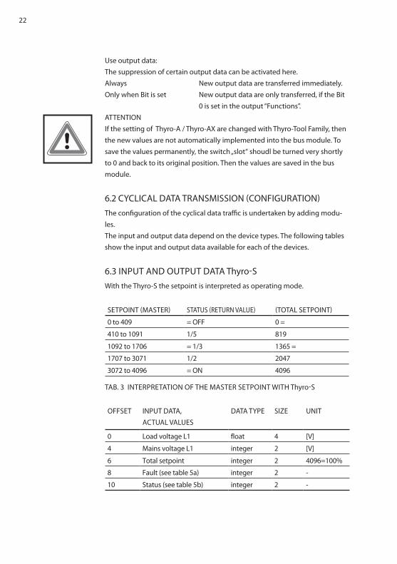
6.3 INPUT AND OUTPUT DATA Thyro-Swith the Thyro-S the setpoint is interpreted as operating mode.
SETPOINT (MASTER) STATUS (RETURN VALUE) (TOTAL SETPOINT)
0 to 409 = OFF 0 =
410 to 1091 1/5 819
1092 to 1706 = 1/3 1365 =
1707 to 3071 1/2 2047
3072 to 4096 = ON 4096
TAB. 3 INTERPRETATION OF ThE MASTER SETPOINT wITh Thyro-S
OFFSET INPUT DATA, ACTUAL VALUES
DATA TyPE SIzE UNIT
0 Load voltage L1 float 4 [V]
4 Mains voltage L1 integer 2 [V]
6 Total setpoint integer 2 4096=100%
8 Fault (see table 5a) integer 2 -
10 Status (see table 5b) integer 2 -
23
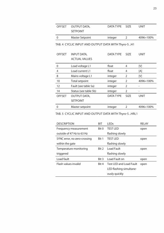
OFFSET OUTPUT DATA, SETPOINT
DATA TyPE SIzE UNIT
0 Master Setpoint integer 2 4096=100%
TAB. 4 CyCLIC INPUT AND OUTPUT DATA wITh Thyro-S ..h1
OFFSET INPUT DATA, ACTUAL VALUES
DATA TyPE SIzE UNIT
0 Load voltage L1 float 4 [V]
4 Load current L1 float 4 [A]
8 Mains voltage L1 integer 2 [V]
10 Total setpoint integer 2 4096=100%
12 Fault (see table 5a) integer 2 -
14 Status (see table 5b) integer 2 -
OFFSET OUTPUT DATA, SETPOINT
DATA TyPE SIzE UNIT
0 Master setpoint integer 2 4096=100%
TAB. 5 CyCLIC INPUT AND OUTPUT DATA wITh Thyro-S ..hRL1
DESCRIPTION BIT LEDs RELAy
Frequency measurement
outside of 47 hz to 63 hz
Bit 0 TEST LED
flashing slowly
open
SyNC error, no zero-crossing
within the gate
Bit 1 TEST LED
flashing slowly
open
Temperature monitoring
triggered
Bit 2 Load Fault
flashing slowly
open
Load fault Bit 3 Load Fault on open
Flash values invalid Bit 4 Test LED and Load Fault
LED flashing simultane-
ously quickly
open
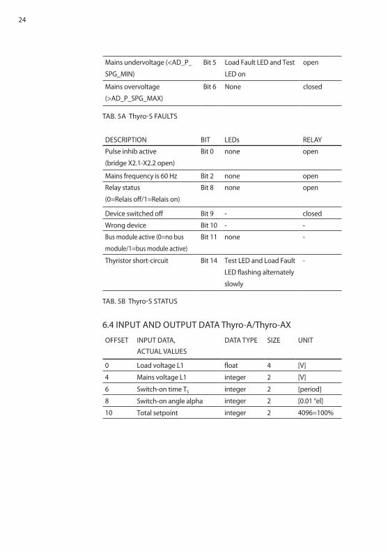
24
Mains undervoltage (<AD_P_
SPg_MIN)
Bit 5 Load Fault LED and Test
LED on
open
Mains overvoltage
(>AD_P_SPg_MAX)
Bit 6 None closed
TAB. 5A Thyro-S FAULTS
DESCRIPTION BIT LEDs RELAy
Pulse inhib active
(bridge X2.1-X2.2 open)
Bit 0 none open
Mains frequency is 60 hz Bit 2 none open
Relay status
(0=Relais off/1=Relais on)
Bit 8 none open
Device switched off Bit 9 - closed
wrong device Bit 10 - -
Bus module active (0=no bus
module/1=bus module active)
Bit 11 none -
Thyristor short-circuit Bit 14 Test LED and Load Fault
LED flashing alternately
slowly
-
TAB. 5B Thyro-S STATUS
6.4 INPUT AND OUTPUT DATA Thyro-A/Thyro-AX
OFFSET INPUT DATA, ACTUAL VALUES
DATA TyPE SIzE UNIT
0 Load voltage L1 float 4 [V]
4 Mains voltage L1 integer 2 [V]
6 Switch-on time TS integer 2 [period]
8 Switch-on angle alpha integer 2 [0.01 °el]
10 Total setpoint integer 2 4096=100%
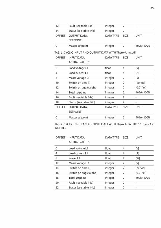
25
12 Fault (see table 14a) integer 2 -
14 Status (see table 14b) integer 2 -
OFFSET OUTPUT DATA, SETPOINT
DATA TyPE SIzE UNIT
0 Master setpoint integer 2 4096=100%
TAB. 6 CyCLIC INPUT AND OUTPUT DATA wITh Thyro-A 1A...h1
OFFSET INPUT DATA, ACTUAL VALUES
DATA TyPE SIzE UNIT
0 Load voltage L1 float 4 [V]
4 Load current L1 float 4 [A]
8 Mains voltage L1 integer 2 [V]
10 Switch-on time TS integer 2 [period]
12 Switch-on angle alpha integer 2 [0.01 °el]
14 Total setpoint integer 2 4096=100%
16 Fault (see table 14a) integer 2 -
18 Status (see table 14b) integer 2 -
OFFSET OUTPUT DATA, SETPOINT
DATA TyPE SIzE UNIT
0 Master setpoint integer 2 4096=100%
TAB. 7 CyCLIC INPUT AND OUTPUT DATA wITh Thyro-A 1A...hRL1/ Thyro-AX 1A..hRL2
OFFSET INPUT DATA, ACTUAL VALUES
DATA TyPE SIzE UNIT
0 Load voltage L1 float 4 [V]
4 Load current L1 float 4 [A]
8 Power L1 float 4 [w]
12 Mains voltage L1 integer 2 [V]
14 Switch-on time TS integer 2 [period]
16 Switch-on angle alpha integer 2 [0.01 °el]
18 Total setpoint integer 2 4096=100%
20 Fault (see table 14a) integer 2 -
22 Status (see table 14b) integer 2 -
26
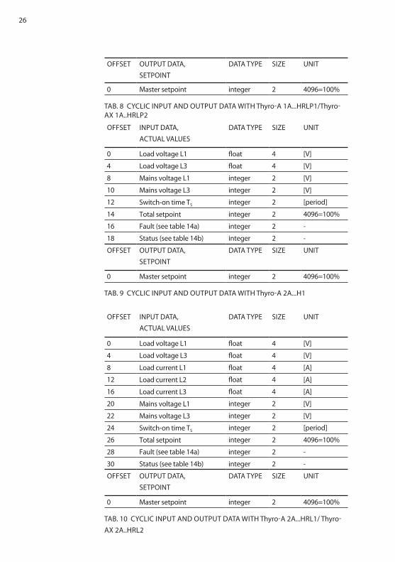
OFFSET OUTPUT DATA, SETPOINT
DATA TyPE SIzE UNIT
0 Master setpoint integer 2 4096=100%
TAB. 8 CyCLIC INPUT AND OUTPUT DATA wITh Thyro-A 1A...hRLP1/Thyro-AX 1A..hRLP2
OFFSET INPUT DATA, ACTUAL VALUES
DATA TyPE SIzE UNIT
0 Load voltage L1 float 4 [V]
4 Load voltage L3 float 4 [V]
8 Mains voltage L1 integer 2 [V]
10 Mains voltage L3 integer 2 [V]
12 Switch-on time TS integer 2 [period]
14 Total setpoint integer 2 4096=100%
16 Fault (see table 14a) integer 2 -
18 Status (see table 14b) integer 2 -
OFFSET OUTPUT DATA, SETPOINT
DATA TyPE SIzE UNIT
0 Master setpoint integer 2 4096=100%
TAB. 9 CyCLIC INPUT AND OUTPUT DATA wITh Thyro-A 2A...h1
OFFSET INPUT DATA, ACTUAL VALUES
DATA TyPE SIzE UNIT
0 Load voltage L1 float 4 [V]
4 Load voltage L3 float 4 [V]
8 Load current L1 float 4 [A]
12 Load current L2 float 4 [A]
16 Load current L3 float 4 [A]
20 Mains voltage L1 integer 2 [V]
22 Mains voltage L3 integer 2 [V]
24 Switch-on time TS integer 2 [period]
26 Total setpoint integer 2 4096=100%
28 Fault (see table 14a) integer 2 -
30 Status (see table 14b) integer 2 -
OFFSET OUTPUT DATA, SETPOINT
DATA TyPE SIzE UNIT
0 Master setpoint integer 2 4096=100%
TAB. 10 CyCLIC INPUT AND OUTPUT DATA wITh Thyro-A 2A...hRL1/ Thyro-AX 2A..hRL2
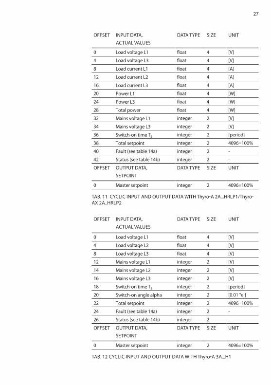
27
OFFSET INPUT DATA, ACTUAL VALUES
DATA TyPE SIzE UNIT
0 Load voltage L1 float 4 [V]
4 Load voltage L3 float 4 [V]
8 Load current L1 float 4 [A]
12 Load current L2 float 4 [A]
16 Load current L3 float 4 [A]
20 Power L1 float 4 [w]
24 Power L3 float 4 [w]
28 Total power float 4 [w]
32 Mains voltage L1 integer 2 [V]
34 Mains voltage L3 integer 2 [V]
36 Switch-on time TS integer 2 [period]
38 Total setpoint integer 2 4096=100%
40 Fault (see table 14a) integer 2 -
42 Status (see table 14b) integer 2 -
OFFSET OUTPUT DATA, SETPOINT
DATA TyPE SIzE UNIT
0 Master setpoint integer 2 4096=100%
TAB. 11 CyCLIC INPUT AND OUTPUT DATA wITh Thyro-A 2A...hRLP1/Thyro-AX 2A..hRLP2
OFFSET INPUT DATA, ACTUAL VALUES
DATA TyPE SIzE UNIT
0 Load voltage L1 float 4 [V]
4 Load voltage L2 float 4 [V]
8 Load voltage L3 float 4 [V]
12 Mains voltage L1 integer 2 [V]
14 Mains voltage L2 integer 2 [V]
16 Mains voltage L3 integer 2 [V]
18 Switch-on time TS integer 2 [period]
20 Switch-on angle alpha integer 2 [0.01 °el]
22 Total setpoint integer 2 4096=100%
24 Fault (see table 14a) integer 2 -
26 Status (see table 14b) integer 2 -
OFFSET OUTPUT DATA, SETPOINT
DATA TyPE SIzE UNIT
0 Master setpoint integer 2 4096=100%
TAB. 12 CyCLIC INPUT AND OUTPUT DATA wITh Thyro-A 3A...h1
28
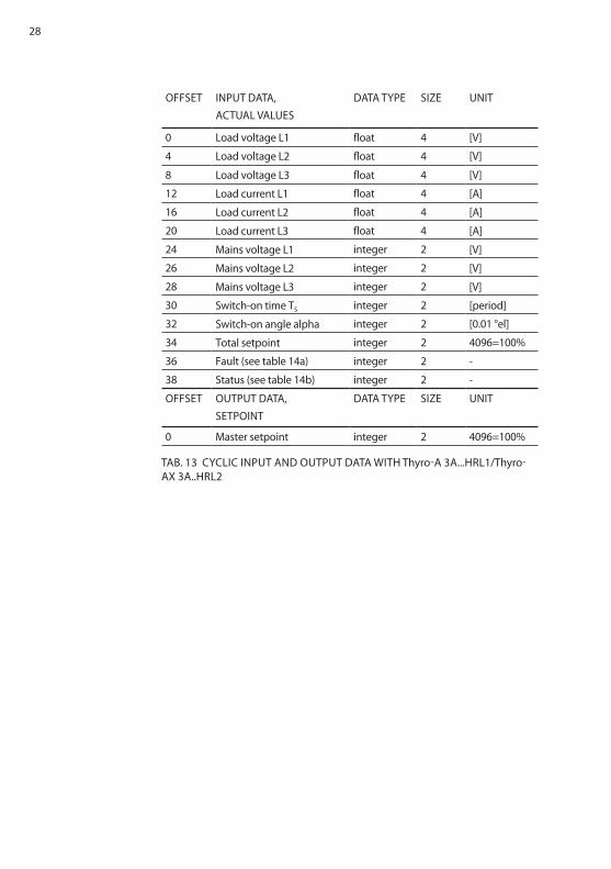
OFFSET INPUT DATA, ACTUAL VALUES
DATA TyPE SIzE UNIT
0 Load voltage L1 float 4 [V]
4 Load voltage L2 float 4 [V]
8 Load voltage L3 float 4 [V]
12 Load current L1 float 4 [A]
16 Load current L2 float 4 [A]
20 Load current L3 float 4 [A]
24 Mains voltage L1 integer 2 [V]
26 Mains voltage L2 integer 2 [V]
28 Mains voltage L3 integer 2 [V]
30 Switch-on time TS integer 2 [period]
32 Switch-on angle alpha integer 2 [0.01 °el]
34 Total setpoint integer 2 4096=100%
36 Fault (see table 14a) integer 2 -
38 Status (see table 14b) integer 2 -
OFFSET OUTPUT DATA, SETPOINT
DATA TyPE SIzE UNIT
0 Master setpoint integer 2 4096=100%
TAB. 13 CyCLIC INPUT AND OUTPUT DATA wITh Thyro-A 3A...hRL1/Thyro-AX 3A..hRL2
29
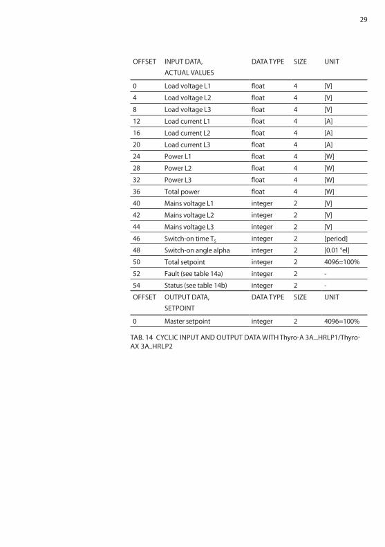
OFFSET INPUT DATA, ACTUAL VALUES
DATA TyPE SIzE UNIT
0 Load voltage L1 float 4 [V]
4 Load voltage L2 float 4 [V]
8 Load voltage L3 float 4 [V]
12 Load current L1 float 4 [A]
16 Load current L2 float 4 [A]
20 Load current L3 float 4 [A]
24 Power L1 float 4 [w]
28 Power L2 float 4 [w]
32 Power L3 float 4 [w]
36 Total power float 4 [w]
40 Mains voltage L1 integer 2 [V]
42 Mains voltage L2 integer 2 [V]
44 Mains voltage L3 integer 2 [V]
46 Switch-on time TS integer 2 [period]
48 Switch-on angle alpha integer 2 [0.01 °el]
50 Total setpoint integer 2 4096=100%
52 Fault (see table 14a) integer 2 -
54 Status (see table 14b) integer 2 -
OFFSET OUTPUT DATA, SETPOINT
DATA TyPE SIzE UNIT
0 Master setpoint integer 2 4096=100%
TAB. 14 CyCLIC INPUT AND OUTPUT DATA wITh Thyro-A 3A...hRLP1/Thyro-AX 3A..hRLP2
30
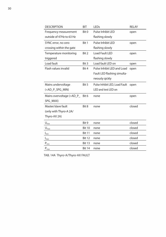
DESCRIPTION BIT LEDs RELAy
Frequency measurement
outside of 47hz to 63 hz
Bit 0 Pulse Inhibit LED
flashing slowly
open
SyNC error, no cero
crossing within the gate
Bit 1 Pulse Inhibit LED
flashing slowly
open
Temperature monitoring
triggered
Bit 2 Load Fault LED
flashing slowly
open
Load fault Bit 3 Load fault LED on open
Flash values invalid Bit 4 Pulse Inhibit LED and Load
Fault LED flashing simulta-
neously qickly
open
Mains undervoltage
(<AD_P_SPg_MIN)
Bit 5 Pulse Inhibit LED, Load Fault
LED and test LED on
open
Mains overvoltage (>AD_P_
SPg_MAX)
Bit 6 none open
Master/slave fault
(only with Thyro-A 2A/
Thyro-AX 2A)
Bit 8 none closed
Umin Bit 9 none closed
Umax Bit 10 none closed
Imin Bit 11 none closed
Imax Bit 12 none closed
Pmin Bit 13 none closed
Pmax Bit 14 none closed
TAB. 14A Thyro-A/Thyro-AX FAULT
31
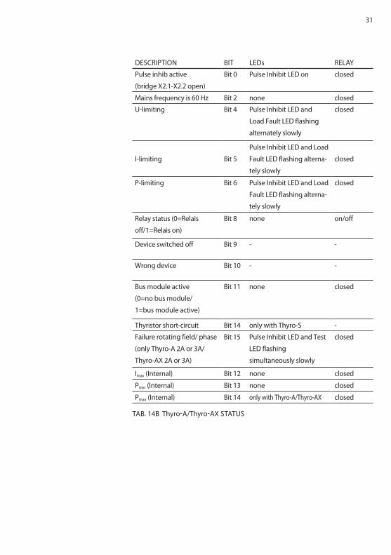
DESCRIPTION BIT LEDs RELAy
Pulse inhib active
(bridge X2.1-X2.2 open)
Bit 0 Pulse Inhibit LED on closed
Mains frequency is 60 hz Bit 2 none closed
U-limiting Bit 4 Pulse Inhibit LED and
Load Fault LED flashing
alternately slowly
closed
I-limiting Bit 5
Pulse Inhibit LED and Load
Fault LED flashing alterna-
tely slowly
closed
P-limiting Bit 6 Pulse Inhibit LED and Load
Fault LED flashing alterna-
tely slowly
closed
Relay status (0=Relais
off/1=Relais on)
Bit 8 none on/off
Device switched off Bit 9 - -
wrong device Bit 10 - -
Bus module active
(0=no bus module/
1=bus module active)
Bit 11 none closed
Thyristor short-circuit Bit 14 only with Thyro-S -
Failure rotating field/ phase
(only Thyro-A 2A or 3A/
Thyro-AX 2A or 3A)
Bit 15 Pulse Inhibit LED and Test
LED flashing
simultaneously slowly
closed
Imax (Internal) Bit 12 none closed
Pmin (Internal) Bit 13 none closed
Pmax (Internal) Bit 14 only with Thyro-A/Thyro-AX closed
TAB. 14B Thyro-A/Thyro-AX STATUS
32
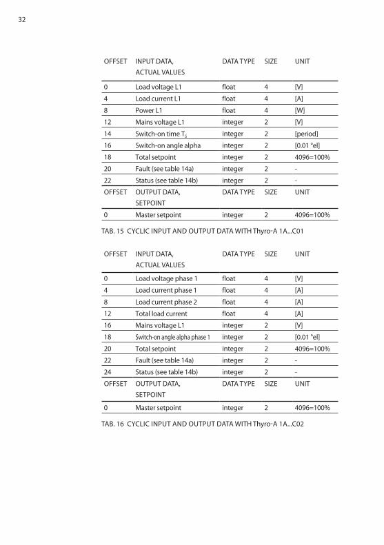
OFFSET INPUT DATA, ACTUAL VALUES
DATA TyPE SIzE UNIT
0 Load voltage L1 float 4 [V]
4 Load current L1 float 4 [A]
8 Power L1 float 4 [w]
12 Mains voltage L1 integer 2 [V]
14 Switch-on time TS integer 2 [period]
16 Switch-on angle alpha integer 2 [0.01 °el]
18 Total setpoint integer 2 4096=100%
20 Fault (see table 14a) integer 2 -
22 Status (see table 14b) integer 2 -
OFFSET OUTPUT DATA, SETPOINT
DATA TyPE SIzE UNIT
0 Master setpoint integer 2 4096=100%
TAB. 15 CyCLIC INPUT AND OUTPUT DATA wITh Thyro-A 1A...C01
OFFSET INPUT DATA, ACTUAL VALUES
DATA TyPE SIzE UNIT
0 Load voltage phase 1 float 4 [V]
4 Load current phase 1 float 4 [A]
8 Load current phase 2 float 4 [A]
12 Total load current float 4 [A]
16 Mains voltage L1 integer 2 [V]
18 Switch-on angle alpha phase 1 integer 2 [0.01 °el]
20 Total setpoint integer 2 4096=100%
22 Fault (see table 14a) integer 2 -
24 Status (see table 14b) integer 2 -
OFFSET OUTPUT DATA, SETPOINT
DATA TyPE SIzE UNIT
0 Master setpoint integer 2 4096=100%
TAB. 16 CyCLIC INPUT AND OUTPUT DATA wITh Thyro-A 1A...C02
33
OFFSET INPUT DATA, ACTUAL VALUES
DATA TyPE SIzE UNIT
0 Load voltage L1 float 4 [V]
4 Load current L1 float 4 [A]
8 Power L1 float 4 [w]
12 Mains voltage L1 integer 2 [V]
14 Switch-on time TS integer 2 [period]
16 Switch-on angle alpha integer 2 [0.01 °el]
18 Total setpoint integer 2 4096=100%
20 Fault (see table 14a) integer 2 -
22 Status (see table 14b) integer 2 -
OFFSET OUTPUT DATA, SETPOINT
DATA TyPE SIzE UNIT
0 Master setpoint integer 2 4096=100%
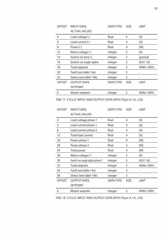
TAB. 17 CyCLIC INPUT AND OUTPUT DATA wITh Thyro-A 1A...C03
OFFSET INPUT DATA, ACTUAL VALUES
DATA TyPE SIzE UNIT
0 Load voltage phase 1 float 4 [V]
4 Load current phase 1 float 4 [A]
8 Load current phase 2 float 4 [A]
12 Total load current float 4 [A]
16 Power phase 1 float 4 [w]
20 Power phase 2 float 4 [w]
24 Total power float 4 [w]
28 Mains voltage L1 integer 2 [V]
30 Switch-on angle alpha phase 1 integer 2 [0.01 °el]
32 Total setpoint integer 2 4096=100%
34 Fault (see table 14a) integer 2 -
36 Status (see table 14b) integer 2 -
OFFSET OUTPUT DATA, SETPOINT
DATA TyPE SIzE UNIT
0 Master setpoint integer 2 4096=100%
TAB. 18 CyCLIC INPUT AND OUTPUT DATA wITh Thyro-A 1A...C05
34
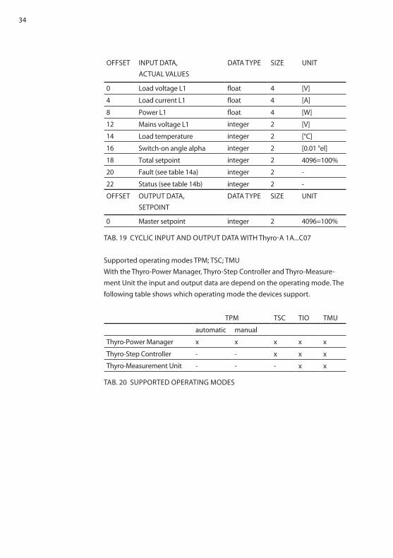
OFFSET INPUT DATA, ACTUAL VALUES
DATA TyPE SIzE UNIT
0 Load voltage L1 float 4 [V]
4 Load current L1 float 4 [A]
8 Power L1 float 4 [w]
12 Mains voltage L1 integer 2 [V]
14 Load temperature integer 2 [°C]
16 Switch-on angle alpha integer 2 [0.01 °el]
18 Total setpoint integer 2 4096=100%
20 Fault (see table 14a) integer 2 -
22 Status (see table 14b) integer 2 -
OFFSET OUTPUT DATA, SETPOINT
DATA TyPE SIzE UNIT
0 Master setpoint integer 2 4096=100%
TAB. 19 CyCLIC INPUT AND OUTPUT DATA wITh Thyro-A 1A...C07
Supported operating modes TPM; TSC; TMUwith the Thyro-Power Manager, Thyro-Step Controller and Thyro-Measure-ment Unit the input and output data are depend on the operating mode. The following table shows which operating mode the devices support.
TPM TSC TIO TMU
automatic manual
Thyro-Power Manager x x x x x
Thyro-Step Controller - - x x x
Thyro-Measurement Unit - - - x x
TAB. 20 SUPPORTED OPERATINg MODES
35
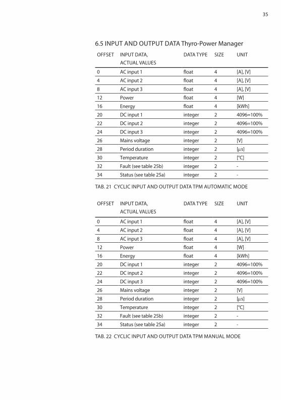
6.5 INPUT AND OUTPUT DATA Thyro-Power Manager
OFFSET INPUT DATA, ACTUAL VALUES
DATA TyPE SIzE UNIT
0 AC input 1 float 4 [A], [V]
4 AC input 2 float 4 [A], [V]
8 AC input 3 float 4 [A], [V]
12 Power float 4 [w]
16 Energy float 4 [kwh]
20 DC input 1 integer 2 4096=100%
22 DC input 2 integer 2 4096=100%
24 DC input 3 integer 2 4096=100%
26 Mains voltage integer 2 [V]
28 Period duration integer 2 [μs]
30 Temperature integer 2 [°C]
32 Fault (see table 25b) integer 2 -
34 Status (see table 25a) integer 2 -
TAB. 21 CyCLIC INPUT AND OUTPUT DATA TPM AUTOMATIC MODE
OFFSET INPUT DATA, ACTUAL VALUES
DATA TyPE SIzE UNIT
0 AC input 1 float 4 [A], [V]
4 AC input 2 float 4 [A], [V]
8 AC input 3 float 4 [A], [V]
12 Power float 4 [w]
16 Energy float 4 [kwh]
20 DC input 1 integer 2 4096=100%
22 DC input 2 integer 2 4096=100%
24 DC input 3 integer 2 4096=100%
26 Mains voltage integer 2 [V]
28 Period duration integer 2 [μs]
30 Temperature integer 2 [°C]
32 Fault (see table 25b) integer 2 -
34 Status (see table 25a) integer 2 -
TAB. 22 CyCLIC INPUT AND OUTPUT DATA TPM MANUAL MODE
36
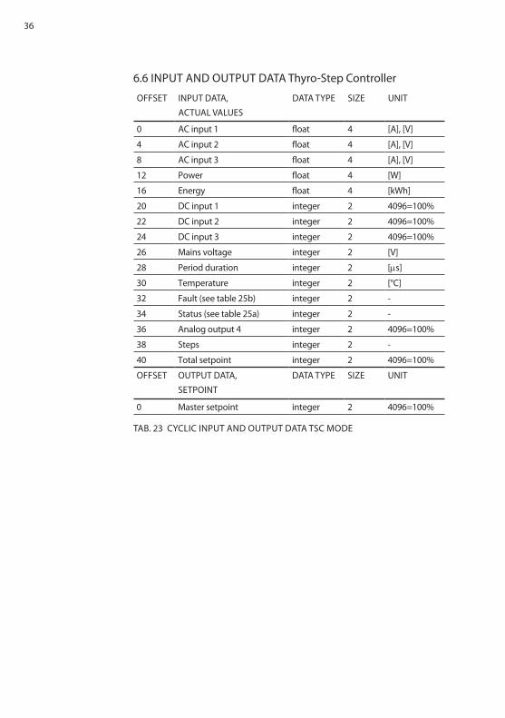
6.6 INPUT AND OUTPUT DATA Thyro-Step Controller
OFFSET INPUT DATA, ACTUAL VALUES
DATA TyPE SIzE UNIT
0 AC input 1 float 4 [A], [V]
4 AC input 2 float 4 [A], [V]
8 AC input 3 float 4 [A], [V]
12 Power float 4 [w]
16 Energy float 4 [kwh]
20 DC input 1 integer 2 4096=100%
22 DC input 2 integer 2 4096=100%
24 DC input 3 integer 2 4096=100%
26 Mains voltage integer 2 [V]
28 Period duration integer 2 [μs]
30 Temperature integer 2 [°C]
32 Fault (see table 25b) integer 2 -
34 Status (see table 25a) integer 2 -
36 Analog output 4 integer 2 4096=100%
38 Steps integer 2 -
40 Total setpoint integer 2 4096=100%
OFFSET OUTPUT DATA, SETPOINT
DATA TyPE SIzE UNIT
0 Master setpoint integer 2 4096=100%
TAB. 23 CyCLIC INPUT AND OUTPUT DATA TSC MODE
37
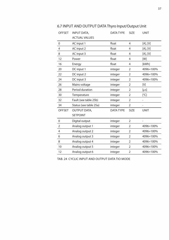
6.7 INPUT AND OUTPUT DATA Thyro Input/Output Unit
OFFSET INPUT DATA, ACTUAL VALUES
DATA TyPE SIzE UNIT
0 AC input 1 float 4 [A], [V]
4 AC input 2 float 4 [A], [V]
8 AC input 3 float 4 [A], [V]
12 Power float 4 [w]
16 Energy float 4 [kwh]
20 DC input 1 integer 2 4096=100%
22 DC input 2 integer 2 4096=100%
24 DC input 3 integer 2 4096=100%
26 Mains voltage integer 2 [V]
28 Period duration integer 2 [μs]
30 Temperature integer 2 [°C]
32 Fault (see table 25b) integer 2 -
34 Status (see table 25a) integer 2 -
OFFSET OUTPUT DATA, SETPOINT
DATA TyPE SIzE UNIT
0 Digital output integer 2 -
2 Analog output 1 integer 2 4096=100%
4 Analog output 2 integer 2 4096=100%
6 Analog output 3 integer 2 4096=100%
8 Analog output 4 integer 2 4096=100%
10 Analog output 5 integer 2 4096=100%
12 Analog output 6 integer 2 4096=100%
TAB. 24 CyCLIC INPUT AND OUTPUT DATA TIO MODE
38
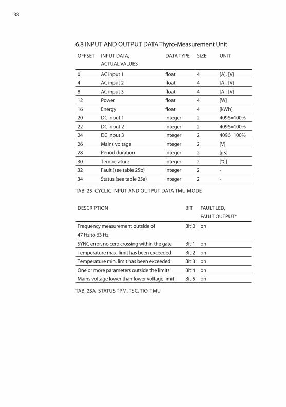
6.8 INPUT AND OUTPUT DATA Thyro-Measurement Unit
OFFSET INPUT DATA, ACTUAL VALUES
DATA TyPE SIzE UNIT
0 AC input 1 float 4 [A], [V]
4 AC input 2 float 4 [A], [V]
8 AC input 3 float 4 [A], [V]
12 Power float 4 [w]
16 Energy float 4 [kwh]
20 DC input 1 integer 2 4096=100%
22 DC input 2 integer 2 4096=100%
24 DC input 3 integer 2 4096=100%
26 Mains voltage integer 2 [V]
28 Period duration integer 2 [μs]
30 Temperature integer 2 [°C]
32 Fault (see table 25b) integer 2 -
34 Status (see table 25a) integer 2 -
TAB. 25 CyCLIC INPUT AND OUTPUT DATA TMU MODE
DESCRIPTION BIT FAULT LED, FAULT OUTPUT*
Frequency measurement outside of
47 hz to 63 hz
Bit 0 on
SyNC error, no cero crossing within the gate Bit 1 on
Temperature max. limit has been exceeded Bit 2 on
Temperature min. limit has been exceeded Bit 3 on
One or more parameters outside the limits Bit 4 on
Mains voltage lower than lower voltage limit Bit 5 on
TAB. 25A STATUS TPM, TSC, TIO, TMU
39
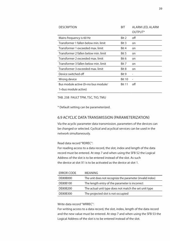
DESCRIPTION BIT ALARM LED, ALARM OUTPUT*
Mains frequency is 60 hz Bit 2 off
Transformer 1 fallen below min. limit Bit 3 on
Transformer 1 exceeded max. limit Bit 4 on
Transformer 2 fallen below min. limit Bit 5 on
Transformer 2 exceeded max. limit Bit 6 on
Transformer 3 fallen below min. limit Bit 7 on
Transformer 3 exceeded max. limit Bit 8 on
Device switched off Bit 9 -
wrong device Bit 10 -
Bus module active (0=no bus module/
1=bus module active)
Bit 11 off
TAB. 25B FAULT TPM, TSC, TIO, TMU
* Default setting can be parameterized.
6.9 ACyCLIC DATA TRANSMISSION (PARAMETERIzATION)Via the acyclic parameter data transmission, parameters of the devices can be changed or selected. Cyclical and acyclical services can be used in the network simultaneously.
Read data record “RDREC”:For reading access to a data record, the slot, index and length of the data record must be entered. At step 7 and when using the SFB 52 the Logical Address of the slot is to be entered instead of the slot. As suchthe device at slot X1 is to be activated as the device at slot 1.
ERROR CODE MEANINg
DE80B000 The unit does not recognize the parameter (invalid index)
DE80B100 The length entry of the parameter is incorrect
DE80B200 The actual unit type does not match the set unit type
DE80B300 The projected slot is not occupied
write data record “wRREC”:For writing access to a data record, the slot, index, length of the data record and the new value must be entered. At step 7 and when using the SFB 53 the Logical Address of the slot is to be entered instead of the slot.
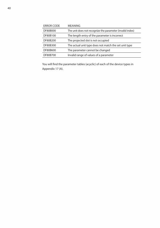
40
ERROR CODE MEANINg
DF80B000 The unit does not recognize the parameter (invalid index)
DF80B100 The length entry of the parameter is incorrect
DF80B200 The projected slot is not occupied
DF80B300 The actual unit type does not match the set unit type
DF80B600 The parameter cannot be changed
DF80B700 Invalid range of values of a parameter
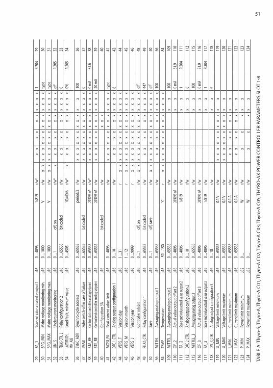
you will find the parameter tables (acyclic) of each of the device types in Appendix 17 (A).
41
7. EXTERNAL CONNECTIONS
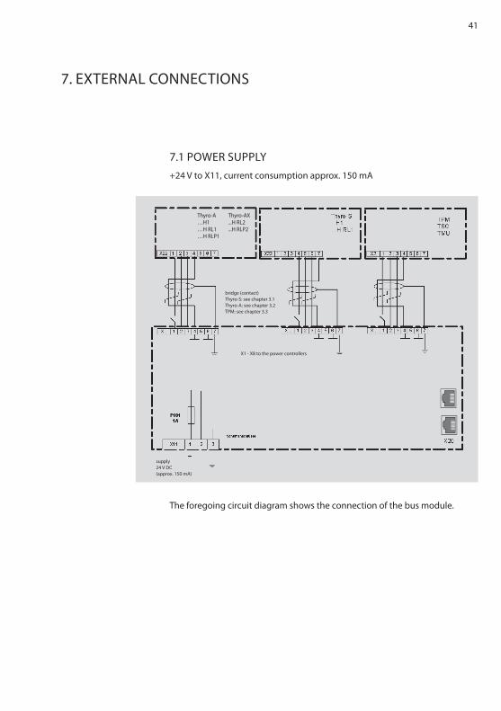
7.1 POwER SUPPLy+24 V to X11, current consumption approx. 150 mA
The foregoing circuit diagram shows the connection of the bus module.
bridge (contact)Thyro-S: see chapter 3.1Thyro-A: see chapter 3.2TPM: see chapter 3.3
X1 - X8 to the power controllers
supply24 V DC (approx. 150 mA)
Thyro-A…h1…h RL1…h RLP1
Thyro-AX...h RL2...h RLP2
42
7.2 OPERATINg ELEMENTS AND TERMINAL BLOCkSThis chapter describes the available terminal blocks, plug connectors and operating elements.Configuration of the 7 pin connector of slots X1 to X8:1 Switched ground potential. All pins 1 of slots X1 – X8 are connec-
ted.2 RxD3 TxD4 ground5 Switchable ground potential. The slots X1 – X8 can be
switched as desired.6 ground7 ground potential for shield connection
Configuration of the 3 pin connector X11:X11: +24VX11: 24V - groundX11: grounding, cable should be as short as possible for EMC reasons
43
8. INTERFACES
8.1 SySTEM INTERFACEThe bus module is connected with the relevant system interfaces of the pow-er controllers via X1 to X8 (four-wire, 2x2 twisted, shared shielding).The transmission rate is 38,400 Bd.The asynchronous characters are transferred with 8bit, no parity, one stop bit. The protocol begins with STX, followed by an identifier, the data, and is concluded with a check sum. Defective protocols are ignored.
8.2 EThERNET INTERFACESCommunication medium CAT 5eNetwork topology tree, star and lineMaximum cable length 100 mPROFINET-participants restricted to the maximum supported num-
ber of devices by the controller usedPNO identification number 0x0188Device ID 0x0001Transmission rate 100 Mbit/s
44
9. CONNECTION DIAgRAMS Thyro-A/Thyro-AX
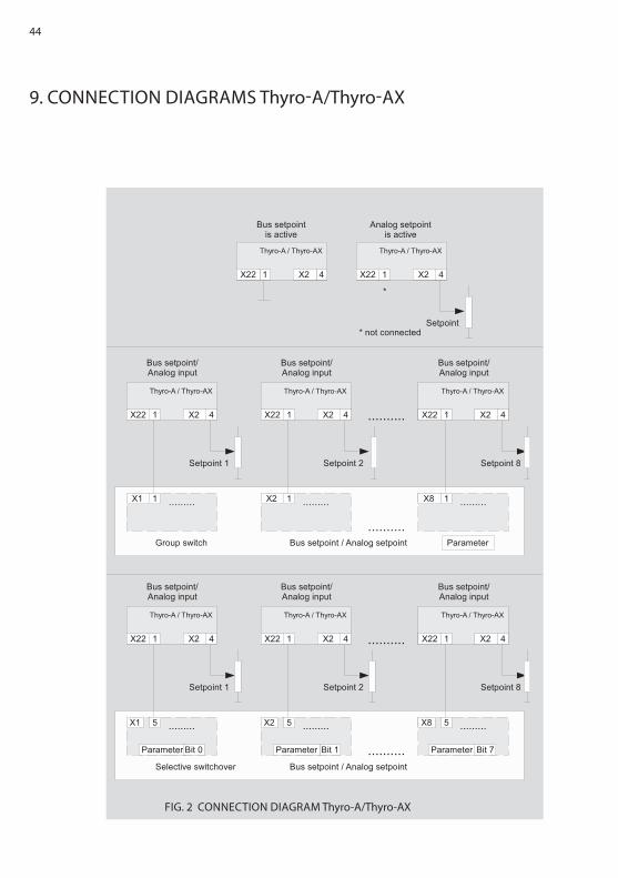
FIg. 2 CONNECTION DIAgRAM Thyro-A/Thyro-AX
45
10. CONNECTION DIAgRAMS Thyro-S
FIg. 3 CONNECTION DIAgRAM Thyro-S
46
11. CONNECTION DIAgRAMS TSC
FIg. 4 CONNECTION DIAgRAM ThyRO-STEP CONTROLLER
47
12. SPECIFIC NOTES
13. TEChNICAL DATA
12.1 INSTALLATIONThe Ethernet bus module PROFINET can be installed in any desired order.
12.2 SERVICEThe devices supplied have been produced in accordance with the quality standard ISO 9001. Should there be faults in spite of this, please contact our Advanced Energy team for assistance (see chapter CONTACT INFORMATION)..
Power supply 24 VDC (+/-20 %) 150 mAConnection options for up to 8 Advanced Energy power control-
lers of series Thyro-S, Thyro-A, Thyro-AX and the Thyro-Power Manager series
Function control LEDAssembly DIN railAmbient temperature maximum 55 °CDimensions (wxDxh): 150 x 60 x 95 mmweight circa: 0.35 kg
48
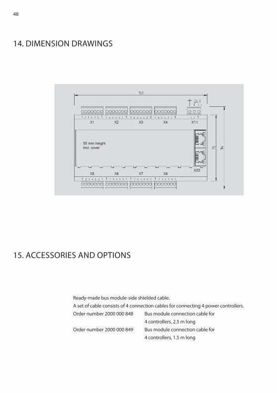
14. DIMENSION DRAwINgS
15. ACCESSORIES AND OPTIONS
Ready-made bus module-side shielded cable.A set of cable consists of 4 connection cables for connecting 4 power controllers.Order number 2000 000 848 Bus module connection cable for
4 controllers, 2.5 m longOrder number 2000 000 849 Bus module connection cable for
4 controllers, 1.5 m long
55 mm heightincl. cover
49
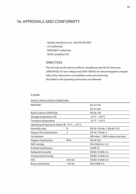
16. APPROVALS AND CONFORMITy
- quality standard in acc. with EN ISO 9001- CE conformity- PROFINET conformity- RohS compliant 5/6
DIRECTIVESThe CE mark on the device confirms compliance with the EC directives 2006/95/EEC for low voltage and 2004/108/EEC for electromagnetic compati-bility if the instructions on installation and commissioningdescribed in the operating instructions are followed.
In detail:
DEVICE APPLICATION CONDITIONS
PROFINET IEC 61158 IEC 61784Built-in device (VDE0160) EN 50 178Storage temperature (D) -25 °C - +55 °CTransport temperature -25 °C - +70 °COperating temperature (better B) -10 °C - +55 °Chumidity class B EN 50 178 tab. 7 (EN 60 721)Degree of contamination 2 EN 50 178 tab. 2Air pressure 900 mbar * 1000 m above sea levelDegree of protection IP00 EN 69 529EMC-testing EN 61000-6-2 (-4)Emitted interference CISPR 16Radiated immunity EN/IEC 61000-4-3Conducted immunity EN/IEC 61000-4-6ESD 8 kV (A) EN/IEC 61000-4-2Burst control lines 1 kV (A) EN 61000-4-4
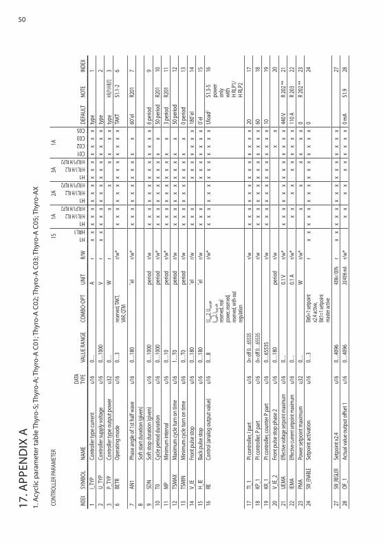
5017
. APP
END
IX A
1. A
cycl
ic p
aram
eter
tabl
e Th
yro-
S; T
hyro
-A; T
hyro
-A C
01; T
hyro
-A C
02; T
hyro
-A C
03; T
hyro
-A C
05; T
hyro
-AX
CONT
ROLL
ER PA
RAM
ETER
1S1A
2A3A
1A
INDEX
SyM
BOL
NAM
EDA
TA
TyPE
VALU
E RAN
gECO
MBO
-OPT
UNIT
R/w
h1hRL1h1h RL1/h RL2h RLP1/h RLP2h1h RL1/h RL2h RLP1/h RLP2h1h RL1/h RL2h RLP1/h RLP2C01C02C03C05
DEFA
ULT
NOTE
INDE
X1
I_TyP
Cont
rolle
r typ
e cur
rent
u16
0…A
rx
xx
xx
xx
xx
xx
xx
xx
type
12
U_Ty
PCo
ntro
ller s
uppl
y vol
tage
u16
0…10
00V
rx
xx
xx
xx
xx
xx
xx
xx
type
23
P_Ty
PCo
ntro
ller t
ype o
utpu
t pow
eru3
20…
wr
xx
xx
xx
type
h RLP1
/h RLP2
36
BETR
Oper
atin
g mod
eu1
60…
3res
erved
, TAkT
, VA
R, qT
Mr/w
*x
xx
xx
xx
xx
xx
xx
TAkT
S1.1-
26
7AN
1Ph
ase a
ngle
of 1s
t half
wav
eu1
60…
180
˚el
r/w*
xx
xx
xx
xx
xx
x60
˚el
R201
78
Soft
start
dura
tion (
give
n)9
SDN
Soft
stop
dura
tion (
give
n)u1
60…
1000
perio
dr/w
xx
xx
xx
xx
xx
xx
x6 p
erio
d9
10T0
Cycle
per
iod
dura
tion
u16
0…10
00pe
riod
r/w*
xx
xx
xx
xx
xx
x50
per
iod
R201
1011
MP
Min
imum
inte
rval
u16
0…10
perio
dr/w
*x
xx
xx
xx
xx
xx
3 per
iod
R201
1112
TSM
AXM
axim
um cy
cle tu
rn on
time
u16
1…T0
perio
dr/w
xx
xx
xx
xx
xx
x50
per
iod
1213
TSM
INM
inim
um cy
cle tu
rn on
time
u16
0…T0
perio
dr/w
xx
xx
xx
xx
xx
x0 p
erio
d13
14V_
IEFr
ont p
ulse
stop
u16
0…18
0˚e
lr/w
xx
xx
xx
xx
xx
180˚
el14
15h_
IEBa
ck p
ulse
stop
u16
0…18
0˚e
lr/w
xx
xx
xx
xx
xx
0˚el
1516
RECo
ntro
l (ana
log o
utpu
t valu
e)u1
60…
8U loa
d2, U loa
d eff,
I load2,
I load eff
, res
erved
, real
powe
r, rese
rved,
reserv
ed, w
ith-ou
t reg
ulatio
n
r/w*
xx
xx
xx
xx
xx
xx
xUl
oad2
S1.3-
5 po
wer
only
with
h
RLP1
/ h
RLP2
16
17TI_
1PI
cont
rolle
r, I p
art
u16
0= off
0…65
535
r/wx
xx
xx
xx
xx
xx
xx
2017
18kP
_1PI
cont
rolle
r, P p
art
u16
0= off
0…65
535
r/wx
xx
xx
xx
xx
xx
xx
6018
19kR
_1PI
cont
rolle
r, cou
nter
P pa
rtu1
60…
6553
5r/w
xx
xx
xx
xx
xx
xx
x10
1920
V_IE_
2Fr
ont p
ulse
stop
pha
se 2
u16
0…18
0pe
riod
r/wx
x20
21UE
MA
Effec
tive v
oltag
e setp
oint m
axim
umu1
60…
0.1 V
r/w*
xx
xx
xx
xx
xx
xx
x44
0 VR 2
02 **
2122
IEMA
Effec
tive c
urren
t setp
oint m
axim
umu1
60…
0.1 A
r/w*
xx
xx
xx
xx
xx
110 A
R 203
2223
PMA
Powe
r set
poin
t max
imum
u32
0…w
r/w*
xx
xx
xx
0R 2
02 **
2324
Sw_E
NABL
ESe
tpoi
nt ac
tivat
ion
u16
0…3
Bit0=
1 setp
oint
x2.4
activ
e, Bit
1=1 s
etpoin
t ma
ster a
ctive
rx
xx
xx
xx
xx
xx
xx
xx
024
27Sw
_REg
LER
Setp
oint
x2.4
u16
0…40
96409
6=100
%r
xx
xx
xx
xx
xx
xx
xx
x27
28OF
_1Ac
tual
valu
e out
put o
ffset
1u1
60…
4096
20/409
6 mA
r/w*
xx
xx
xx
xx
xx
0 mA
S1.9
28
51
29FA
_1Sc
ale en
d valu
e actu
al valu
e outp
ut 1
u16
0…40
961/
819
r/w*
xx
xx
xx
xx
xx
1R 2
0429
30SP
g_M
INM
ains v
olta
ge m
onito
ring m
in.
u16
0…10
00V
r/wx
xx
xx
xx
xx
xx
xx
xx
type
3031
SPg_
MAX
Main
s vol
tage
mon
itorin
g max
.u1
60…
1000
Vr/w
x
xx
xx
xx
xx
xx
xx
xx
type
3132
UN_S
Unde
rcurre
nt m
onito
ring
u16
0…1
off, o
nr/w
*x
xx
xx
xx
xx
xx
offR 2
0532
33REL
AIS_CT
RL_2
Relay
confi
gura
tion 2
u16
0…65
535
bit c
oded
r/wx
xx
xx
xx
xx
x0
3334
LASTB
RUCh
_MI
N_AB
SLo
ad fa
ult, m
inim
um va
lue
u16
0…45
05100
/4096%
r/w*
xx
xx
xx
xx
xx
x0%
R 205
34
36Sy
NC_A
DRSy
nchr
o cyc
le ad
dres
su1
60…
6553
5pe
riod/
2r/w
xx
xx
xx
xx
xx
x10
036
37IM
ABPu
lse sw
itch-
off in
case
of fa
ilure
u16
0…65
535
bit c
oded
r/wx
xx
xx
xx
xx
xx
xx
037
38ST
A_RE
Contr
ol sta
rt con
troller
analo
g setp
oint
u16
0…65
535
20/409
6 mA
r/w*
xx
xx
xx
xx
xx
xx
x0 m
AS1
.638
39ST
E_RE
Contr
ol en
d con
trolle
r ana
log se
tpoint
u16
0…65
535
20/409
6 mA
r/wx
xx
xx
xx
xx
xx
xx
20 m
A39
40Co
nfigu
ratio
n 3A
u16
bit c
oded
r/wx
xx
4041
MOS
I_FA
Peak
curre
nt va
lue l
imit
u16
0…40
96r/w
xx
xx
xx
xx
xx
xx
xty
pe41
42DA
C_1_C
TRL
Analo
g out
put c
onfig
urat
ion 1
u16
0…10
r/wx
xx
xx
xx
xx
x6
4244
VERS
_TVe
rsion
day
u16
1…31
rx
xx
xx
xx
xx
xx
xx
xx
4445
VERS
_MVe
rsion
mon
thu1
61…
12r
xx
xx
xx
xx
xx
xx
xx
x45
46VE
RS_J
Versi
on ye
aru1
60…
9999
rx
xx
xx
xx
xx
xx
xx
xx
4648
Cont
rolle
r inhi
bit
u16
0…1
off, o
nr/w
xx
xx
xx
xx
xx
xx
xx
xoff
4849
RELA
IS_CT
RLRe
lay co
nfigu
ratio
n 1u1
60…
6553
5bi
t cod
edr/w
xx
xx
xx
xx
xx
447
4950
Save
u16
0…1
off, s
ave
r/wx
xx
xx
xx
xx
xx
xx
xx
off50
56M
ITTE
LAv
erag
ing a
nalo
g out
put 1
u16
0…65
535
r/wx
xx
xx
xx
xx
x10
056
84TE
MP
Tem
pera
ture
u16
-50…
150
°Cr
xx
xx
xx
xx
xx
xx
xx
x84
109
MIT
TEL_
2Av
erag
ing a
nalo
g out
put 2
u16
0…65
535
r/wx
x10
010
911
0OF
_2Ac
tual
valu
e out
put o
ffset
2u1
60…
4096
20/409
6 mA
r/wx
x0 m
AS1
.911
011
1FA
_2Sc
ale en
d valu
e actu
al va
lue ou
tput 2
u16
0…40
961/
819
r/wx
x1
R 204
111
112
DAC_
2_CTR
LAn
alog o
utpu
t con
figur
ation
2u1
60…
10r/w
xx
611
211
5M
ITTE
L_3
Avera
ging a
nalog
outp
ut 3
u16
0…65
535
r/wx
x10
011
511
6OF
_3Ac
tual
valu
e out
put o
ffset
3u1
60…
4096
20/409
6 mA
r/wx
x0 m
AS1
.911
611
7FA
_3Sc
ale en
d valu
e actu
al va
lue ou
tput 3
u16
0…40
961/
819
r/wx
x1
R 204
117
118
DAC_
3_CTR
LAn
alog o
utpu
t con
figur
ation
3u1
60…
10r/w
xx
611
811
9U_
MIN
Volta
ge lim
it min
imum
u16
0…65
535
0.1 V
r/wx
xx
xx
xx
xx
xx
119
120
U_M
AXVo
ltage
limit m
axim
umu1
60…
6553
50.1
Vr/w
xx
xx
xx
xx
xx
x12
012
1I_M
INCu
rrent
limit m
inim
umu1
60…
6553
50.1
Ar/w
xx
xx
xx
xx
121
122
I_MAX
Curre
nt lim
it max
imum
u16
0…65
535
0.1 A
r/wx
xx
xx
xx
x12
212
3P_
MIN
Powe
r lim
it min
imum
u32
0…w
r/wx
xx
xx
123
124
P_M
AXPo
wer li
mit m
axim
umu3
20…
wr/w
xx
xx
x12
4
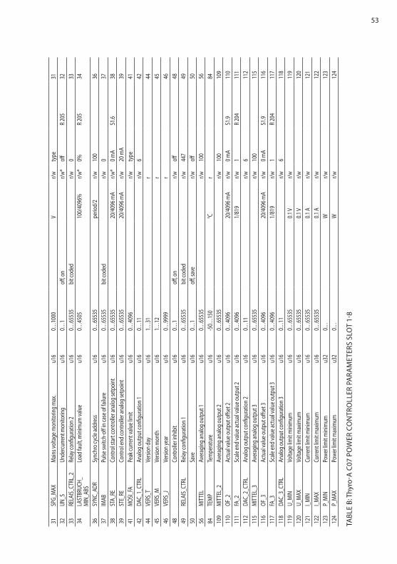
TABL
E A:
Thy
ro-S
; Thy
ro-A
; Thy
ro-A
C01
; Thy
ro-A
C02
; Thy
ro-A
C03
; Thy
ro-A
C05
; Th
yRO
-AX
POw
ER C
ON
TRO
LLER
PA
RAM
ETER
S SL
OT
1-8
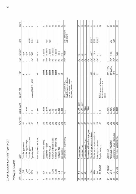
522.
Acy
clic
par
amet
er ta
ble
Thyr
o-A
C07
CONT
ROLL
ER PA
RAM
ETER
INDEX
SyM
BOL
NAM
EDA
TA Ty
PEVA
LUE R
ANgE
COM
BO-O
PTUN
ITR/
wDE
FAUL
TNO
TEIN
DEX
1I_T
yPCo
ntro
ller t
ype c
urre
ntu1
60…
Ar
type
12
U_Ty
PCo
ntro
ller s
uppl
y vol
tage
u16
0…10
00V
rty
pe2
3P_
TyP
Cont
rolle
r typ
e out
put p
ower
u32
0…w
rty
peh
RLP1
36
BETR
Oper
atin
g mod
eu1
60…
3re
serv
ed, T
AkT,
VAR,
qTM
r/w*
TAkT
S1.1-
26
7AN
1Ph
ase a
ngle
of 1s
t half
wav
eu1
60…
180
˚el
r/w*
60˚e
lR2
017
9SD
NSo
ft sto
p du
ratio
n (gi
ven)
u16
0…10
00pe
riod
r/w6 p
erio
d9
10T0
Cycle
per
iod
dura
tion
u16
0…10
00pe
riod
r/w*
50 p
erio
dR2
0110
11M
PM
inim
um in
terv
alu1
60…
10pe
riod
r/w*
3 per
iod
R201
1112
TSM
AXM
axim
um cy
cle tu
rn on
time
u16
1…T0
perio
dr/w
50 p
erio
d12
13TS
MIN
Min
imum
cycle
turn
on tim
eu1
60…
T0pe
riod
r/w0 p
erio
d13
14V_
IEFr
ont p
ulse
stop
u16
0…18
0˚e
lr/w
180˚
el14
15h_
IEBa
ck p
ulse
stop
u16
0…18
0˚e
lr/w
0˚el
1516
RECo
ntro
l (ana
log o
utpu
t valu
e)u1
60…
9Ul
oad2
, Uloa
d eff,
Iload
2, Ilo
ad eff
, rese
rved
, real
powe
r, res
erve
d, res
erve
d, wi
thou
t reg
ulatio
n, te
mpe
ratur
e
r/w*
Uloa
d2S1
.3-5 p
ower
only
with
h RL
P116
17TI_
1PI
cont
rolle
r, I p
art
u16
0= off
0…65
535
r/w20
1718
kP_1
PI co
ntro
ller, P
par
tu1
60=
off 0…
6553
5r/w
6018
19kR
_1PI
cont
rolle
r, cou
nter
P pa
rtu1
60…
6553
5r/w
1019
20Te
mpe
ratur
e coe
fficien
t of th
e hea
ting t
ape
u16
0…65
535
r/w20
21UE
MA
Effec
tive v
olta
ge se
tpoi
nt m
axim
umu1
60…
0.1 V
r/w*
440 V
R 202
**21
22IEM
AEff
ectiv
e cur
rent
setp
oint
max
imum
u16
0…0.1
Ar/w
*11
0 AR 2
0322
23PM
APo
wer s
etpo
int m
axim
umu3
20…
wr/w
*0
R 202
**23
24Sw
_ENA
BLE
Setp
oint
activ
atio
nu1
60…
3Bi
t0=1
setp
oint
x2.4
activ
e, Bi
t1=1
setp
oint
mas
ter
activ
e
r0
24
27Sw
_REg
LER
Setp
oint
x2.4
u16
0…40
9640
96=1
00%
r27
28OF
_1Ac
tual
valu
e out
put o
ffset
1u1
60…
4096
20/4
096m
Ar/w
*0 m
AS1
.928
29FA
_1Sc
ale en
d va
lue a
ctua
l valu
e out
put 1
u16
0…40
961/
819
r/w*
1R 2
0429
30SP
g_M
INM
ains v
olta
ge m
onito
ring m
in.
u16
0…10
00V
r/wty
pe30
53
31SP
g_M
AXM
ains v
olta
ge m
onito
ring m
ax.
u16
0…10
00V
r/w
type
3132
UN_S
Unde
rcurre
nt m
onito
ring
u16
0…1
off, o
nr/w
*off
R 205
3233
RELA
IS_CT
RL_2
Relay
confi
gura
tion 2
u16
0…65
535
bit c
oded
r/w0
3334
LAST
BRUC
h_M
IN_A
BSLo
ad fa
ult, m
inim
um va
lue
u16
0…45
0510
0/40
96%
r/w*
0%R 2
0534
36Sy
NC_A
DRSy
nchr
o cyc
le ad
dres
su1
60…
6553
5pe
riod/
2r/w
100
3637
IMAB
Pulse
switc
h-off
in ca
se of
failu
reu1
60…
6553
5bi
t cod
edr/w
037
38ST
A_RE
Cont
rol s
tart
cont
rolle
r ana
log s
etpo
int
u16
0…65
535
20/4
096 m
Ar/w
*0 m
AS1
.638
39ST
E_RE
Cont
rol e
nd co
ntro
ller a
nalo
g set
poin
tu1
60…
6553
520
/409
6 mA
r/w20
mA
3941
MOS
I_FA
Peak
curre
nt va
lue l
imit
u16
0…40
96r/w
type
4142
DAC_
1_CT
RLAn
alog o
utpu
t con
figur
atio
n 1u1
60…
11r/w
642
44VE
RS_T
Versi
on d
ayu1
61…
31r
4445
VERS
_MVe
rsion
mon
thu1
61…
12r
4546
VERS
_JVe
rsion
year
u16
0…99
99r
4648
Cont
rolle
r inhi
bit
u16
0…1
off, o
nr/w
off48
49RE
LAIS_
CTRL
Relay
confi
gura
tion 1
u16
0…65
535
bit c
oded
r/w44
749
50Sa
veu1
60…
1off
, sav
er/w
off50
56M
ITTE
LAv
erag
ing a
nalo
g out
put 1
u16
0…65
535
r/w10
056
84TE
MP
Tem
pera
ture
u16
-50…
150
°Cr
8410
9M
ITTE
L_2
Aver
agin
g ana
log o
utpu
t 2u1
60…
6553
5r/w
100
109
110
OF_2
Actu
al va
lue o
utpu
t offs
et 2
u16
0…40
9620
/409
6 mA
r/w0 m
AS1
.911
011
1FA
_2Sc
ale en
d va
lue a
ctua
l valu
e out
put 2
u16
0…40
961/
819
r/w1
R 204
111
112
DAC_
2_CT
RLAn
alog o
utpu
t con
figur
atio
n 2u1
60…
11r/w
611
211
5M
ITTE
L_3
Aver
agin
g ana
log o
utpu
t 3u1
60…
6553
5r/w
100
115
116
OF_3
Actu
al va
lue o
utpu
t offs
et 3
u16
0…40
9620
/409
6 mA
r/w0 m
AS1
.911
611
7FA
_3Sc
ale en
d va
lue a
ctua
l valu
e out
put 3
u16
0…40
961/
819
r/w1
R 204
117
118
DAC_
3_CT
RLAn
alog o
utpu
t con
figur
atio
n 3u1
60…
11r/w
611
811
9U_
MIN
Volta
ge lim
it min
imum
u16
0…65
535
0.1 V
r/w11
912
0U_
MAX
Volta
ge lim
it max
imum
u16
0…65
535
0.1 V
r/w12
012
1I_M
INCu
rrent
limit m
inim
umu1
60…
6553
50.1
Ar/w
121
122
I_MAX
Curre
nt lim
it max
imum
u16
0…65
535
0.1 A
r/w12
212
3P_
MIN
Powe
r lim
it min
imum
u32
0…w
r/w12
312
4P_
MAX
Powe
r lim
it max
imum
u32
0…w
r/w12
4
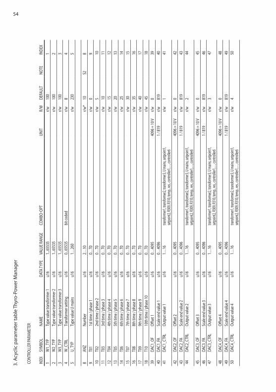
TABL
E B:
Thy
ro-A
C07
PO
wER
CO
NTR
OLL
ER P
ARA
MET
ERS
SLO
T 1-
8
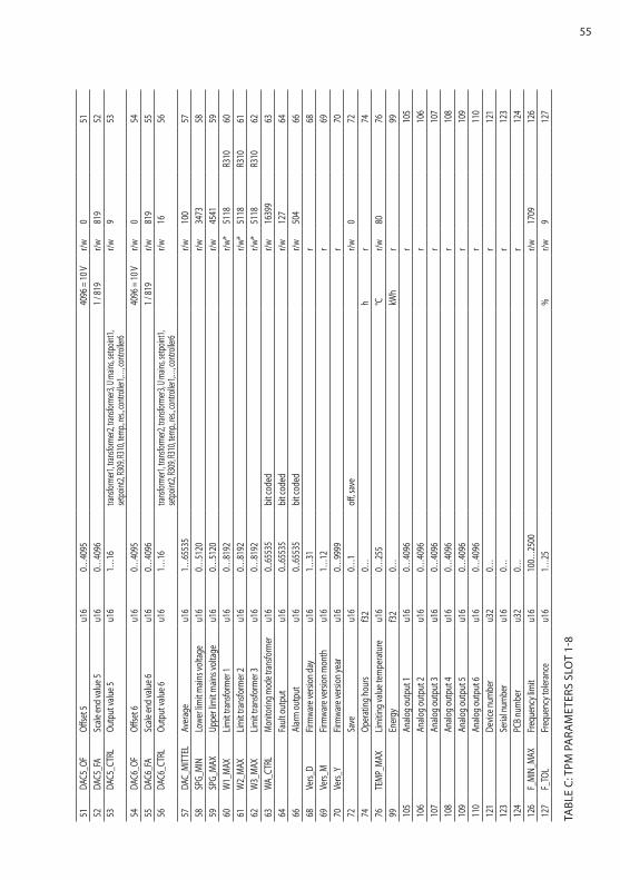
543.
Acy
clic
par
amet
er ta
ble
Thyr
o-Po
wer
Man
ager
CONT
ROLL
ER PA
RAM
ETER
INDEX
SyM
BOL
NAM
EDA
TA Ty
PEVA
LUE R
ANgE
COM
BO-O
PTUN
ITR/
wDE
FAUL
TNO
TEIN
DEX
1w
1_Ty
PTy
pe va
lue t
rans
form
er 1
u16
1...65
535
r/w10
01
2w
2_Ty
PTy
pe va
lue t
rans
form
er 2
u16
1...65
535
r/w10
02
3w
3_Ty
PTy
pe va
lue t
rans
form
er 3
u16
1...65
535
r/w10
03
4w
_CTR
LTr
ansfo
rmer
setti
ngu1
60..
.6553
5bi
t cod
edr/w
84
5U_
TyP
Type
valu
e U m
ains
u16
1…26
0r/w
230
5
8AN
zNu
mbe
ru1
62…
10r/w
*10
S28
9T0
11s
t tim
e / p
hase
1u1
60…
T0r/w
09
10T0
22n
d tim
e / p
hase
2u1
60…
T0r/w
510
11T0
33r
d tim
e / p
hase
3u1
60…
T0r/w
1011
12T0
44t
h tim
e / p
hase
4u1
60…
T0r/w
1512
13T0
55t
h tim
e / p
hase
5u1
60…
T0r/w
2013
14T0
66t
h tim
e / p
hase
6u1
60…
T0r/w
2514
15T0
77t
h tim
e / p
hase
7u1
60…
T0r/w
3015
16T0
88t
h tim
e / p
hase
8u1
60…
T0r/w
3516
17T0
99t
h tim
e / p
hase
9u1
60…
T0r/w
4017
18T1
010
th tim
e / p
hase
10u1
60…
T0r/w
4518
39DA
C1_O
FOff
set 1
u16
0…40
9540
96 =
10 V
r/w0
3940
DAC1
_FA
Scale
end
valu
e 1u1
60…
4096
1 / 81
9r/w
819
4041
DAC1
_CTR
LOu
tput
valu
e 1u1
61…
16tra
nsfor
mer1,
trans
forme
r2, tra
nsfor
mer3,
U ma
ins, se
tpoint
1, set
point
2, R3
09, R
310,
temp.,
res.,
contr
oller1
,…, co
ntroll
er6r/w
141
42DA
C2_O
FOff
set 2
u16
0…40
9540
96 =
10 V
r/w0
4243
DAC2
_FA
Scale
end
valu
e 2u1
60…
4096
1 / 81
9r/w
819
4344
DAC2
_CTR
LOu
tput
valu
e 2u1
61…
16tra
nsfor
mer1,
trans
forme
r2, tra
nsfor
mer3,
U ma
ins, se
tpoint
1, set
point
2, R3
09, R
310,
temp.,
res.,
contr
oller1
,…, co
ntroll
er6r/w
244
45DA
C3_O
FOff
set 3
u16
0…40
9540
96 =
10 V
r/w0
4546
DAC3
_FA
Scale
end
valu
e 3u1
60…
4096
1 / 81
9r/w
819
4647
DAC3
_CTR
LOu
tput
valu
e 3u1
61…
16tra
nsfor
mer1,
trans
forme
r2, tra
nsfor
mer3,
U ma
ins, se
tpoint
1, set
point
2, R3
09, R
310,
temp.,
res.,
contr
oller1
,…, co
ntroll
er6r/w
347
48DA
C4_O
FOff
set 4
u16
0…40
9540
96 =
10 V
r/w0
4849
DAC4
_FA
Scale
end
valu
e 4u1
60…
4096
1 / 81
9r/w
819
4950
DAC4
_CTR
LOu
tput
valu
e 4u1
61…
16tra
nsfor
mer1,
trans
forme
r2, tra
nsfor
mer3,
U ma
ins, se
tpoint
1, set
point
2, R3
09, R
310,
temp.,
res.,
contr
oller1
,…, co
ntroll
er6r/w
450
55
51DA
C5_O
FOff
set 5
u16
0…40
9540
96 =
10 V
r/w0
5152
DAC5
_FA
Scale
end
valu
e 5u1
60…
4096
1 / 81
9r/w
819
5253
DAC5
_CTR
LOu
tput
valu
e 5u1
61…
16tra
nsfor
mer1,
trans
forme
r2, tra
nsfor
mer3,
U ma
ins, se
tpoint
1, set
point
2, R3
09, R
310,
temp.,
res.,
contr
oller1
,…, co
ntroll
er6r/w
953
54DA
C6_O
FOff
set 6
u16
0…40
9540
96 =
10 V
r/w0
5455
DAC6
_FA
Scale
end
valu
e 6u1
60…
4096
1 / 81
9r/w
819
5556
DAC6
_CTR
LOu
tput
valu
e 6u1
61…
16tra
nsfor
mer1,
trans
forme
r2, tra
nsfor
mer3,
U ma
ins, se
tpoint
1, set
point
2, R3
09, R
310,
temp.,
res.,
contr
oller1
,…, co
ntroll
er6r/w
1656
57DA
C_M
ITTE
LAv
erag
eu1
61…
6553
5r/w
100
5758
SPg_
MIN
Lowe
r lim
it main
s vol
tage
u16
0…51
20r/w
3473
5859
SPg_
MAX
Uppe
r lim
it main
s vol
tage
u16
0…51
20r/w
4541
5960
w1_
MAX
Limit t
rans
form
er 1
u16
0…81
92r/w
*51
18R3
1060
61w
2_M
AXLim
it tra
nsfo
rmer
2u1
60…
8192
r/w*
5118
R310
6162
w3_
MAX
Limit t
rans
form
er 3
u16
0…81
92r/w
*51
18R3
1062
63w
A_CT
RLMo
nitor
ing m
ode t
ransfo
rmer
u16
0...65
535
bit c
oded
r/w16
399
6364
Faul
t out
put
u16
0...65
535
bit c
oded
r/w12
764
66Al
arm
outp
utu1
60..
.6553
5bi
t cod
edr/w
504
6668
Vers_
DFir
mwa
re ve
rsion
day
u16
1…31
r68
69Ve
rs_M
Firm
ware
versi
on m
onth
u16
1…12
r69
70Ve
rs_y
Firm
ware
versi
on ye
aru1
60…
9999
r70
72Sa
veu1
60…
1off
, sav
er/w
072
74Op
erat
ing h
ours
f32
0…h
r74
76TE
MP_
MAX
Limiti
ng va
lue t
empe
ratu
reu1
60…
255
°Cr/w
8076
99En
ergy
f32
0…kw
hr
9910
5An
alog o
utpu
t 1u1
60…
4096
r10
510
6An
alog o
utpu
t 2u1
60…
4096
r10
610
7An
alog o
utpu
t 3u1
60…
4096
r10
710
8An
alog o
utpu
t 4u1
60…
4096
r10
810
9An
alog o
utpu
t 5u1
60…
4096
r10
911
0An
alog o
utpu
t 6u1
60…
4096
r11
012
1De
vice n
umbe
ru3
20…
r12
112
3Se
rial n
umbe
ru1
60…
r12
312
4PC
B num
ber
u32
0…r
124
126
F_M
IN_M
AXFr
eque
ncy l
imit
u16
100…
2500
r/w17
0912
612
7F_
TOL
Freq
uenc
y tol
eran
ceu1
61…
25%
r/w9
127
TABL
E C:
TPM
PA
RAM
ETER
S SL
OT
1-8
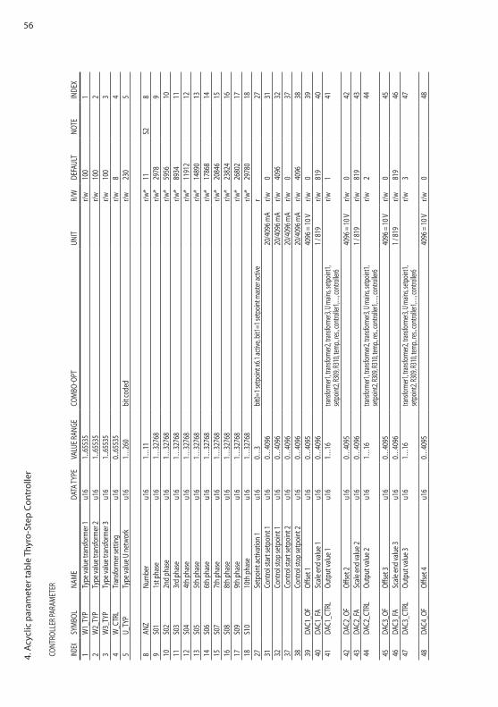
564.
Acy
clic
par
amet
er ta
ble
Thyr
o-St
ep C
ontr
olle
r
CONT
ROLL
ER PA
RAM
ETER
INDEX
SyM
BOL
NAM
EDA
TA Ty
PEVA
LUE R
ANgE
COM
BO-O
PTUN
ITR/
wDE
FAUL
TNO
TEIN
DEX
1w
1_Ty
PTy
pe va
lue t
rans
form
er 1
u16
1...65
535
r/w10
01
2w
2_Ty
PTy
pe va
lue t
rans
form
er 2
u16
1...65
535
r/w10
02
3w
3_Ty
PTy
pe va
lue t
rans
form
er 3
u16
1...65
535
r/w10
03
4w
_CTR
LTr
ansfo
rmer
setti
ngu1
60..
.6553
5r/w
84
5U_
TyP
Type
valu
e U ne
twor
ku1
61…
260
bit c
oded
r/w23
05
8AN
zNu
mbe
ru1
61…
11r/w
*11
S28
9S0
11s
t pha
seu1
61…
3276
8r/w
*29
789
10S0
22n
d ph
ase
u16
1…32
768
r/w*
5956
1011
S03
3rd
phas
eu1
61…
3276
8r/w
*89
3411
12S0
44t
h pha
seu1
61…
3276
8r/w
*11
912
1213
S05
5th p
hase
u16
1…32
768
r/w*
1489
013
14S0
66t
h pha
seu1
61…
3276
8r/w
*17
868
1415
S07
7th p
hase
u16
1…32
768
r/w*
2084
615
16S0
88t
h pha
seu1
61…
3276
8r/w
*23
824
1617
S09
9th p
hase
u16
1…32
768
r/w*
2680
217
18S1
010
th p
hase
u16
1…32
768
r/w*
2978
018
27Se
tpoi
nt ac
tivat
ion 1
u16
0…3
bit0=
1 setp
oint x
6.1 ac
tive,
bit1=
1 setp
oint m
aster
activ
er
2731
Cont
rol s
tart
setp
oint
1u1
60…
4096
20/4
096 m
Ar/w
031
32Co
ntro
l sto
p se
tpoi
nt 1
u16
0…40
9620
/409
6 mA
r/w40
9632
37Co
ntro
l sta
rt se
tpoi
nt 2
u16
0…40
9620
/409
6 mA
r/w0
3738
Cont
rol s
top
setp
oint
2u1
60…
4096
20/4
096 m
Ar/w
4096
3839
DAC1
_OF
Offse
t 1u1
60…
4095
4096
= 10
Vr/w
039
40DA
C1_F
ASc
ale en
d va
lue 1
u16
0…40
961 /
819
r/w81
940
41DA
C1_C
TRL
Outp
ut va
lue 1
u16
1…16
trans
forme
r1, tra
nsfor
mer2,
trans
forme
r3, U
mains
, setpo
int1,
setpo
int2,
R309
, R31
0, tem
p., re
s., co
ntroll
er1,…
, contr
oller6
r/w1
41
42DA
C2_O
FOff
set 2
u16
0…40
9540
96 =
10 V
r/w0
4243
DAC2
_FA
Scale
end
valu
e 2u1
60…
4096
1 / 81
9r/w
819
4344
DAC2
_CTR
LOu
tput
valu
e 2u1
61…
16tra
nsfor
mer1,
trans
forme
r2, tra
nsfor
mer3,
U ma
ins, se
tpoint
1, set
point
2, R3
09, R
310,
temp.,
res.,
contr
oller1
,…, co
ntroll
er6r/w
244
45DA
C3_O
FOff
set 3
u16
0…40
9540
96 =
10 V
r/w0
4546
DAC3
_FA
Scale
end
valu
e 3u1
60…
4096
1 / 81
9r/w
819
4647
DAC3
_CTR
LOu
tput
valu
e 3u1
61…
16tra
nsfor
mer1,
trans
forme
r2, tra
nsfor
mer3,
U ma
ins, se
tpoint
1, set
point
2, R3
09, R
310,
temp.,
res.,
contr
oller1
,…, co
ntroll
er6r/w
347
48DA
C4_O
FOff
set 4
u16
0…40
9540
96 =
10 V
r/w0
48
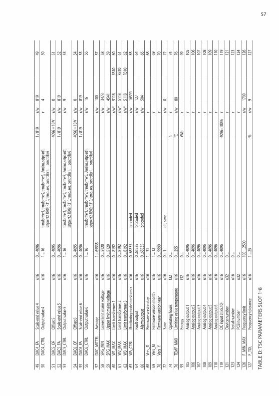
57
49DA
C4_F
ASc
ale en
d va
lue 4
u16
0…40
961 /
819
r/w81
949
50DA
C4_C
TRL
Outp
ut va
lue 4
u16
1…16
trans
forme
r1, tra
nsfor
mer2,
trans
forme
r3, U
mains
, setpo
int1,
setpo
int2,
R309
, R31
0, tem
p., re
s., co
ntroll
er1,…
, contr
oller6
r4
50
51DA
C5_O
FOff
set 5
u16
0…40
9540
96 =
10 V
r/w0
5152
DAC5
_FA
Scale
end
valu
e 5u1
60…
4096
1 / 81
9r/w
819
5253
DAC5
_CTR
LOu
tput
valu
e 5u1
61…
16tra
nsfor
mer1,
trans
forme
r2, tra
nsfor
mer3,
U ma
ins, se
tpoint
1, set
point
2, R3
09, R
310,
temp.,
res.,
contr
oller1
,…, co
ntroll
er6r/w
953
54DA
C6_O
FOff
set 6
u16
0…40
9540
96 =
10 V
r/w0
5455
DAC6
_FA
Scale
end
valu
e 6u1
60…
4096
1 / 81
9r/w
819
5556
DAC6
_CTR
LOu
tput
valu
e 6u1
61…
16tra
nsfor
mer1,
trans
forme
r2, tra
nsfor
mer3,
U ma
ins, se
tpoint
1, set
point
2, R3
09, R
310,
temp.,
res.,
contr
oller1
,…, co
ntroll
er6r/w
1656
57DA
C_M
ITTE
LAv
erag
eu1
61…
6553
5r/w
100
5758
SPg_
MIN
Lowe
r lim
it main
s vol
tage
u16
0…51
20r/w
3473
5859
SPg_
MAX
Uppe
r lim
it main
s vol
tage
u16
0…51
20r/w
4541
5960
w1_
MAX
Limit t
rans
form
er 1
u16
0…81
92r/w
*51
18R3
1060
61w
2_M
AXLim
it tra
nsfo
rmer
2u1
60…
8192
r/w*
5118
R310
6162
w3_
MAX
Limit t
rans
form
er 3
u16
0…81
92r/w
*51
18R3
1062
63w
A_CT
RLMo
nitor
ing m
ode t
ransfo
rmer
u16
0...65
535
bit c
oded
r/w16
399
6364
Faul
t out
put
u16
0...65
535
bit c
oded
r/w12
764
66Al
arm
outp
utu1
60..
.6553
5bi
t cod
edr/w
504
6668
Vers_
DFir
mwa
re ve
rsion
day
u16
1…31
r68
69Ve
rs_M
Firm
ware
versi
on m
onth
u16
1…12
r69
70Ve
rs_y
Firm
ware
versi
on ye
aru1
60…
9999
r70
72Sa
veu1
60…
1off
, sav
er/w
072
74Op
erat
ing h
ours
f32
0…h
r74
76TE
MP_
MAX
Limiti
ng va
lue t
empe
ratu
reu1
60…
255
°Cr/w
8076
99En
ergy
f32
0…kw
hr
9910
5An
alog o
utpu
t 1u1
60…
4096
r10
510
6An
alog o
utpu
t 2u1
60…
4096
r10
610
7An
alog o
utpu
t 3u1
60…
4096
r10
710
8An
alog o
utpu
t 4u1
60…
4096
r10
810
9An
alog o
utpu
t 5u1
60…
4096
r10
911
0An
alog o
utpu
t 6u1
60…
4096
r11
011
9DC
inpu
t 3 (x
5.10)
u16
0…40
9640
96=1
00%
r11
912
1De
vice n
umbe
ru3
20…
r12
112
3Se
rial n
umbe
ru1
60…
r12
312
4PC
B num
ber
u32
0…r
124
126
F_M
IN_M
AXFr
eque
ncy l
imit
u16
100…
2500
r/w17
0912
612
7F_
TOL
Freq
uenc
y tol
eran
ceu1
61…
25%
r/w9
127
TABL
E D
: TSC
PA
RAM
ETER
S SL
OT
1-8
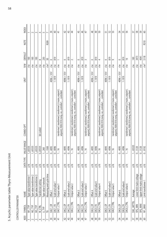
585.
Acy
clic
par
amet
er ta
ble
Thyr
o-M
easu
rem
ent U
nit
CONT
ROLL
ER PA
RAM
ETER
INDEX
SyM
BOL
NAM
EDA
TA Ty
PEVA
LUE R
ANgE
COM
BO-O
PTUN
ITR/
wDE
FAUL
TNO
TEIN
DEX
1w
1_Ty
PTy
pe va
lue t
rans
form
er 1
u16
1...65
535
r/w10
01
2w
2_Ty
PTy
pe va
lue t
rans
form
er 2
u16
1...65
535
r/w10
02
3w
3_Ty
PTy
pe va
lue t
rans
form
er 3
u16
1...65
535
r/w10
03
4w
_CTR
LTr
ansfo
rmer
setti
ngu1
60..
.6553
5bi
t cod
edr/w
84
5U_
TyP
Type
valu
e U ne
twor
ku1
61…
260
r/w23
05
7T0
Mea
surin
g and
cycle
time
u16
1…15
00r/w
*50
R309
739
DAC1
_OF
Offse
t 1u1
60…
4095
4096
= 10
Vr/w
039
40DA
C1_F
ASc
ale en
d va
lue 1
u16
0…40
961 /
819
r/w81
940
41DA
C1_C
TRL
Outp
ut va
lue 1
u16
1…16
trans
forme
r1, tra
nsfor
mer2,
trans
forme
r3, U
mains
, setpo
int1,
setpo
int2,
R309
, R31
0, tem
p., re
s., co
ntroll
er1,…
, contr
oller6
r/w1
41
42DA
C2_O
FOff
set 2
u16
0…40
9540
96 =
10 V
r/w0
4243
DAC2
_FA
Scale
end
valu
e 2u1
60…
4096
1 / 81
9r/w
819
4344
DAC2
_CTR
LOu
tput
valu
e 2u1
61…
16tra
nsfor
mer1,
trans
forme
r2, tra
nsfor
mer3,
U ma
ins, se
tpoint
1, set
point
2, R3
09, R
310,
temp.,
res.,
contr
oller1
,…, co
ntroll
er6r/w
244
45DA
C3_O
FOff
set 3
u16
0…40
9540
96 =
10 V
r/w0
4546
DAC3
_FA
Scale
end
valu
e 3u1
60…
4096
1 / 81
9r/w
819
4647
DAC3
_CTR
LOu
tput
valu
e 3u1
61…
16tra
nsfor
mer1,
trans
forme
r2, tra
nsfor
mer3,
U ma
ins, se
tpoint
1, set
point
2, R3
09, R
310,
temp.,
res.,
contr
oller1
,…, co
ntroll
er6r/w
347
48DA
C4_O
FOff
set 4
u16
0…40
9540
96 =
10 V
r/w0
4849
DAC4
_FA
Scale
end
valu
e 4u1
60…
4096
1 / 81
9r/w
819
4950
DAC4
_CTR
LOu
tput
valu
e 4u1
61…
16tra
nsfor
mer1,
trans
forme
r2, tra
nsfor
mer3,
U ma
ins, se
tpoint
1, set
point
2, R3
09, R
310,
temp.,
res.,
contr
oller1
,…, co
ntroll
er6r/w
450
51DA
C5_O
FOff
set 5
u16
0…40
9540
96 =
10 V
r/w0
5152
DAC5
_FA
Scale
end
valu
e 5u1
60…
4096
1 / 81
9r/w
819
5253
DAC5
_CTR
LOu
tput
valu
e 5u1
61…
16tra
nsfor
mer1,
trans
forme
r2, tra
nsfor
mer3,
U ma
ins, se
tpoint
1, set
point
2, R3
09, R
310,
temp.,
res.,
contr
oller1
,…, co
ntroll
er6r/w
953
54DA
C6_O
FOff
set 6
u16
0…40
9540
96 =
10 V
r/w0
5455
DAC6
_FA
Scale
end
valu
e 6u1
60…
4096
1 / 81
9r/w
819
5556
DAC6
_CTR
LOu
tput
valu
e 6u1
61…
16tra
nsfor
mer1,
trans
forme
r2, tra
nsfor
mer3,
U ma
ins, se
tpoint
1, set
point
2, R3
09, R
310,
temp.,
res.,
contr
oller1
,…, co
ntroll
er6r/w
1656
57DA
C_M
ITTE
LAv
erag
eu1
61…
6553
5r/w
100
5758
SPg_
MIN
Lowe
r lim
it main
s vol
tage
u16
0…51
20r/w
3473
5859
SPg_
MAX
Uppe
r lim
it main
s vol
tage
u16
0…51
20r/w
4541
5960
w1_
MAX
Limit t
rans
form
er 1
u16
0…81
92r/w
*51
18R3
1060
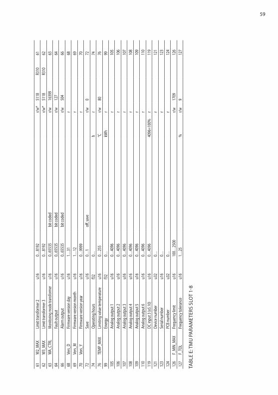
59
61w
2_M
AXLim
it tra
nsfo
rmer
2u1
60…
8192
r/w*
5118
R310
6162
w3_
MAX
Limit t
rans
form
er 3
u16
0…81
92r/w
*51
18R3
1062
63w
A_CT
RLMo
nitor
ing m
ode t
ransfo
rmer
u16
0...65
535
bit c
oded
r/w16
399
6364
Faul
t out
put
u16
0...65
535
bit c
oded
r/w12
764
66Al
arm
outp
utu1
60..
.6553
5bi
t cod
edr/w
504
6668
Vers_
DFir
mwa
re ve
rsion
day
u16
1…31
r68
69Ve
rs_M
Firm
ware
versi
on m
onth
u16
1…12
r69
70Ve
rs_y
Firm
ware
versi
on ye
aru1
60…
9999
r70
72Sa
veu1
60…
1off
, sav
er/w
072
74Op
erat
ing h
ours
f32
0…h
r74
76TE
MP_
MAX
Limiti
ng va
lue t
empe
ratu
reu1
60…
255
°Cr/w
8076
99En
ergy
f32
0…kw
hr
9910
5An
alog o
utpu
t 1u1
60…
4096
r10
510
6An
alog o
utpu
t 2u1
60…
4096
r10
610
7An
alog o
utpu
t 3u1
60…
4096
r10
710
8An
alog o
utpu
t 4u1
60…
4096
r10
810
9An
alog o
utpu
t 5u1
60…
4096
r10
911
0An
alog o
utpu
t 6u1
60…
4096
r11
011
9DC
inpu
t 3 (x
5.10)
u16
0…40
9640
96=1
00%
r11
912
1De
vice n
umbe
ru3
20…
r12
112
3Se
rial n
umbe
ru1
60…
r12
312
4PC
B num
ber
u32
0…r
124
126
F_M
IN_M
AXFr
eque
ncy l
imit
u16
100…
2500
r/w17
0912
612
7F_
TOL
Freq
uenc
y tol
eran
ceu1
61…
25%
r/w9
127
TABL
E E:
TM
U P
ARA
MET
ERS
SLO
T 1-
8
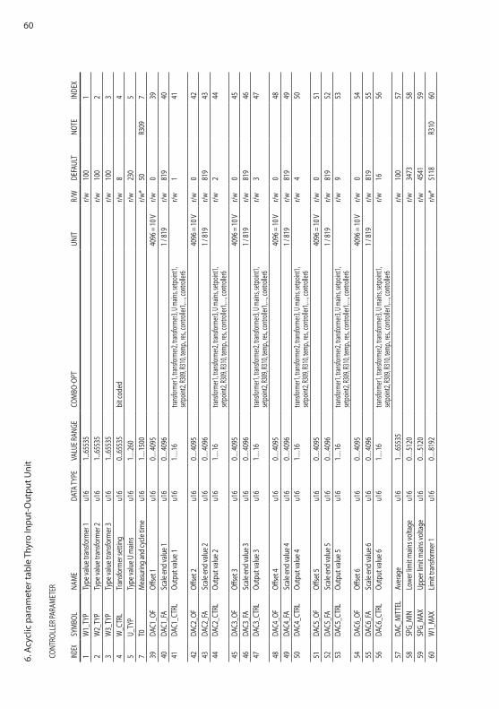
606.
Acy
clic
par
amet
er ta
ble
Thyr
o In
put-
Out
put U
nit
CONT
ROLL
ER PA
RAM
ETER
INDEX
SyM
BOL
NAM
EDA
TA Ty
PEVA
LUE R
ANgE
COM
BO-O
PTUN
ITR/
wDE
FAUL
TNO
TEIN
DEX
1w
1_Ty
PTy
pe va
lue t
rans
form
er 1
u16
1...65
535
r/w10
01
2w
2_Ty
PTy
pe va
lue t
rans
form
er 2
u16
1...65
535
r/w10
02
3w
3_Ty
PTy
pe va
lue t
rans
form
er 3
u16
1...65
535
r/w10
03
4w
_CTR
LTr
ansfo
rmer
setti
ngu1
60..
.6553
5bi
t cod
edr/w
84
5U_
TyP
Type
valu
e U m
ains
u16
1…26
0r/w
230
57
T0M
easu
ring a
nd cy
cle tim
eu1
61…
1500
r/w*
50R3
097
39DA
C1_O
FOff
set 1
u16
0…40
9540
96 =
10 V
r/w0
3940
DAC1
_FA
Scale
end
valu
e 1u1
60…
4096
1 / 81
9r/w
819
4041
DAC1
_CTR
LOu
tput
valu
e 1u1
61…
16tra
nsfor
mer1,
trans
forme
r2, tra
nsfor
mer3,
U ma
ins, se
tpoint
1, set
point
2, R3
09, R
310,
temp.,
res.,
contr
oller1
,…, co
ntroll
er6r/w
141
42DA
C2_O
FOff
set 2
u16
0…40
9540
96 =
10 V
r/w0
4243
DAC2
_FA
Scale
end
valu
e 2u1
60…
4096
1 / 81
9r/w
819
4344
DAC2
_CTR
LOu
tput
valu
e 2u1
61…
16tra
nsfor
mer1,
trans
forme
r2, tra
nsfor
mer3,
U ma
ins, se
tpoint
1, set
point
2, R3
09, R
310,
temp.,
res.,
contr
oller1
,…, co
ntroll
er6r/w
244
45DA
C3_O
FOff
set 3
u16
0…40
9540
96 =
10 V
r/w0
4546
DAC3
_FA
Scale
end
valu
e 3u1
60…
4096
1 / 81
9r/w
819
4647
DAC3
_CTR
LOu
tput
valu
e 3u1
61…
16tra
nsfor
mer1,
trans
forme
r2, tra
nsfor
mer3,
U ma
ins, se
tpoint
1, set
point
2, R3
09, R
310,
temp.,
res.,
contr
oller1
,…, co
ntroll
er6r/w
347
48DA
C4_O
FOff
set 4
u16
0…40
9540
96 =
10 V
r/w0
4849
DAC4
_FA
Scale
end
valu
e 4u1
60…
4096
1 / 81
9r/w
819
4950
DAC4
_CTR
LOu
tput
valu
e 4u1
61…
16tra
nsfor
mer1,
trans
forme
r2, tra
nsfor
mer3,
U ma
ins, se
tpoint
1, set
point
2, R3
09, R
310,
temp.,
res.,
contr
oller1
,…, co
ntroll
er6r/w
450
51DA
C5_O
FOff
set 5
u16
0…40
9540
96 =
10 V
r/w0
5152
DAC5
_FA
Scale
end
valu
e 5u1
60…
4096
1 / 81
9r/w
819
5253
DAC5
_CTR
LOu
tput
valu
e 5u1
61…
16tra
nsfor
mer1,
trans
forme
r2, tra
nsfor
mer3,
U ma
ins, se
tpoint
1, set
point
2, R3
09, R
310,
temp.,
res.,
contr
oller1
,…, co
ntroll
er6r/w
953
54DA
C6_O
FOff
set 6
u16
0…40
9540
96 =
10 V
r/w0
5455
DAC6
_FA
Scale
end
valu
e 6u1
60…
4096
1 / 81
9r/w
819
5556
DAC6
_CTR
LOu
tput
valu
e 6u1
61…
16tra
nsfor
mer1,
trans
forme
r2, tra
nsfor
mer3,
U ma
ins, se
tpoint
1, set
point
2, R3
09, R
310,
temp.,
res.,
contr
oller1
,…, co
ntroll
er6r/w
1656
57DA
C_M
ITTE
LAv
erag
eu1
61…
6553
5r/w
100
5758
SPg_
MIN
Lowe
r lim
it main
s vol
tage
u16
0…51
20r/w
3473
5859
SPg_
MAX
Uppe
r lim
it main
s vol
tage
u16
0…51
20r/w
4541
5960
w1_
MAX
Limit t
rans
form
er 1
u16
0…81
92r/w
*51
18R3
1060

61
61w
2_M
AXLim
it tra
nsfo
rmer
2u1
60…
8192
r/w*
5118
R310
6162
w3_
MAX
Limit t
rans
form
er 3
u16
0…81
92r/w
*51
18R3
1062
63w
A_CT
RLMo
nitor
ing m
ode t
ransfo
rmer
u16
0...65
535
bit c
oded
r/w16
399
6364
Faul
t out
put
u16
0...65
535
bit c
oded
r/w12
764
66Al
arm
outp
utu1
60..
.6553
5bi
t cod
edr/w
504
6668
Vers_
DFir
mwa
re ve
rsion
day
u16
1…31
r68
69Ve
rs_M
Firm
ware
versi
on m
onth
u16
1…12
r69
70Ve
rs_y
Firm
ware
versi
on ye
aru1
60…
9999
r70
72Sa
veu1
60…
1off
, sav
er/w
072
74Op
erat
ing h
ours
f32
0…h
r74
76TE
MP_
MAX
Limiti
ng va
lue t
empe
ratu
reu1
60…
255
°Cr/w
8076
99En
ergy
f32
0…kw
hr
9910
5An
alog o
utpu
t 1u1
60…
4096
r10
510
6An
alog o
utpu
t 2u1
60…
4096
r10
610
7An
alog o
utpu
t 3u1
60…
4096
r10
710
8An
alog o
utpu
t 4u1
60…
4096
r10
810
9An
alog o
utpu
t 5u1
60…
4096
r10
911
0An
alog o
utpu
t 6u1
60…
4096
r11
011
9DC
inpu
t 3 (x
5.10)
u16
0…40
9640
96=1
00%
r11
912
1De
vice n
umbe
ru3
20…
r12
112
3Se
rial n
umbe
ru1
60…
r12
312
4PC
B num
ber
u32
0…r
124
126
F_M
IN_M
AXFr
eque
ncy l
imit
u16
100…
2500
r/w17
0912
612
7F_
TOL
Freq
uenc
y tol
eran
ceu1
61…
25%
r/w9
127
TABL
E F:
TIO
PA
RAM
ETER
S SL
OT
1-8

62
world headquarters
1625 Sharp Point Drive
Fort Collins, CO 80525 USA
970.221.4670 Main
970.221.5583 Fax
www.advanced-energy.com
Specifications are subject to change without notice.
© 2014 Advanced Energy Industries, Inc. All rights reserved. Advanced Energy® and Thyro-S™, Thyro-A™, Thyro-AX™ are trademarks of Advanced Energy Industries, Inc.

63