burnham composites process equivalency test plan … 2263e7 rev... · burnham composites process...
TRANSCRIPT

September 19, 2007 NTP 2263E7 Rev -
Page 1 of 22
Document No.: NTP 2263E7
Burnham Composites Process Equivalency Test Plan For Cytec Cycom 5250-5 3K70PW T650 fabric with 36% RC
FAA Special Project Number SP4613WI-Q
Prepared by: Yeow Ng, John Tomblin, Ric Abbott Reviewed by: John Adelmann, Kit Bowman, Bret Brummer (Hawker Beechcraft Corp), Allison Crockett (General Atomics), Susan Daggett (ATK), Jim Diepenbrock, Rich Fields, Warren Hatfield (Hawker Beechcraft Corp), Jeff Hendrix, Ed Hooper, Robert Glenn (Gulfstream), Dana Granville (U.S. Army), Erkan Kececi (Cessna), Jim Krone (Cessna), Guillermo Mayorga, William McCarvill (Commercial Chemistries), Mark Ofsthun (Spirit AeroSystems), David Ostrodka (FAA), Glen Otzinger (Toyota Aircraft), Dusty Penn (ACG), Chris Ridgard (ACG), Carl Rousseau (Lockheed Martin Aero), Engin Sabuncu (Cessna), Peter Shyprykevich (FAA), Mario Simard (Bombardier), Brent Stevenson (Texas Composite), Kristin Strole (NCAMP), Melanie Violette (Hawker Beechcraft Corp), Stephen Ward (SW Composites), Bill Webb (Cytec), Cytec Engineered Materials, Hexcel Corporation, Spirit AeroSystems. Approved by:
Material Supplier Contact: Kim Gingras Program Manager Business Jet & Rotorcraft Cytec Engineered Materials Tel: (410) 939-8172 Email: [email protected]
Burnham Composites Contact: Darrel Dugan Burnham Composites, Inc. 4203 W. Harry Wichita, KS 67209 Tel: 316-946-5900, Fax: 815-550-4188 [email protected]

September 19, 2007 NTP 2263E7 Rev -
Page 2 of 22
TABLE OF CONTENTS 1. INTRODUCTION ...............................................................................................................................................5 2. TEST METHODS ..............................................................................................................................................5 3. PANEL AND SPECIMEN IDENTIFICATION................................................................................................6 4. UNCURED PREPREG AND RESIN TESTING............................................................................................8 5. CURED LAMINATE PHYSICAL TESTING ..................................................................................................8 6. CURED LAMINA AND LAMINATE MECHANICAL PROPERTY TESTING ..........................................9
6.1 ENVIRONMENTAL CONDITIONING ...............................................................................................................9 6.2 NON-AMBIENT TESTING............................................................................................................................10 6.3 PROCESS DEFINITION ..............................................................................................................................11
7. OTHER TEST PROCEDURES .....................................................................................................................11 7.1 TACK TEST (REF. CESSNA AIRCRAFT COMPANY SPECIFICATION CPTI003): .......................................11 7.2 DRAPE TEST .............................................................................................................................................12
8. NOMINAL CURED PLY THICKNESS AND NORMALIZATION.............................................................12 9. MECHANICAL TESTING ..............................................................................................................................13 10. INSPECTION, CONFORMANCE, WITNESSING, AND SHIPPING ..................................................14 11. DATA REDUCTION AND REPORTING.................................................................................................15 12. SPECIFICATIONS .....................................................................................................................................16 13. REFERENCES............................................................................................................................................16 14. REVISIONS .................................................................................................................................................16 APPENDIX 1 .............................................................................................................................................................17 APPENDIX 2 .............................................................................................................................................................19 APPENDIX 3 .............................................................................................................................................................20
September 19, 2007 NTP 2263E7 Rev -
Page 3 of 22
ABBREVIATIONS AND ACRONYMS ACO Aircraft Certification Office AMS Aerospace Material Specification ANOVA ANalysis Of VAriance ASAP Agate Statistical Analysis Program ASME American Society of Mechanical Engineers ASTM American Society for Testing and Materials BMI Bismaleimide CLC Combined Loading Compression CMH-17 Composite Materials Handbook 17 (formerly MIL-HDBK-17) CPT Cured Ply Thickness CTD Cold Temperature Dry CV Coefficient of Variation DAR Designated Airworthiness Representative DER Designated Engineering Representative DMA Dynamic Mechanical Analysis DMIR Designated Manufacturing Inspection Representative DoD Department of Defense DSC Differential Scanning Calorimetry ETD Elevated Temperature Dry ETW Elevated Temperature Wet FAA Federal Aviation Administration FAW Fiber Areal Weight FTIR Fourier Transform Infrared Spectroscopy FV Fiber Volume fraction HPLC High Performance Liquid Chromatography IAB Industry Advisory Board (an NCAMP Board) IR Infrared spectroscopy ILT Inter-Laminar Tension MIDO Manufacturing Inspection District Office NASA National Aeronautics and Space Administration NCAMP National Center for Advanced Materials Performance NDI Non-Destructive Inspection NIAR National Institute for Aviation Research NIST National Institute of Standards and Technology OEM Original Equipment Manufacturer PCD Process Control Document QA Quality Assurance QC Quality Control QI Quasi-Isotropic RH Relative Humidity RTD Room Temperature Dry SACMA Suppliers of Advanced Composite Materials Association SAE Society of Automotive Engineers SBS Short Beam Strength

September 19, 2007 NTP 2263E7 Rev -
Page 4 of 22
Tg Glass Transition Temperature TGA Thermogravimetric Analyzer WSU Wichita State University

September 19, 2007 NTP 2263E7 Rev -
Page 5 of 22
1. Introduction
This document is a process equivalency test plan for Cytec Cycom 5250-5 3K70PW T650 plain weave fabric prepreg, procured to NCAMP specification NMS 226/3. Panels using one batch of material will be fabricated by Burnham Composites, Inc. per NCAMP process specification NPS 81226 baseline cure cycle. The one batch material is intended for process equivalency purposes, where its test results will be statistically compared with those obtained from NTP 2263Q1 three batch material qualification. The purpose is to demonstrate that Burnham Composites, Inc. is capable of processing the material and producing test panels with properties equivalent to those of the original qualification. More information about this process equivalency and its limitations can be found in Section 6 of DOT/FAA/AR-03/19 and Section 8.4.1 of MIL-HDBK-17-1F. If deemed appropriate, the equivalency data may be pooled with the qualification data to create a larger dataset. The data generated under this program is intended for general distribution to the public, either freely or at a price that does not exceed the cost of reproduction (e.g. printing) and distribution (e.g. postage). Data subjected to export control regulations, if any, will be made available on a case by case basis through written request to NCAMP. The following product form will be used:
Prepreg Name Description About the Prepreg
Cytec Cycom 5250-5 T650 3K plain weave fabric prepreg
Resin name: Cytec Cycom 5250-5, Reinforcement: 3K Plain Weave T650, Sizing: 1% UC 309, Fiber Areal Weight: 193 gsm, Resin Content: 36%
The following material code will be used throughout this document to reference the prepreg:
Material Code Prepreg Name C23 Cytec Cycom 5250-5 T650 3K plain weave fabric prepreg
2. Test Methods
All testing will be in accordance with nationally recognized standards, methods and procedures. Specific mechanical property test methods applicable to the test program in this document include: • ASTM D2344/D2344M-00(2006) – Standard Test Method for Short-Beam Strength of
Polymer Matrix Composite Materials and Their Laminates • ASTM D3039/D3039M-00(2006) – Standard Test Method for Tensile Properties of
Polymer Matrix Composite Materials • ASTM D3518/D3518M-94(2007) – Standard Test Method for In-Plane Shear Response
of Polymer Matrix Composite Materials by Tensile Test of a ± 45º Laminate In-Plane Shear Strength and Modulus
• ASTM D5766/D5766M-02a – Standard Test Method for Open Hole Tensile Strength of Polymer Matrix Composite Laminates
September 19, 2007 NTP 2263E7 Rev -
Page 6 of 22
• ASTM D5961/D5961M-05e1 – Standard Test Method for Bearing Response of Polymer Matrix Composite Laminates
• ASTM D6484/D6484M-04 – Standard Test Method for Open-Hole Compressive Strength of Polymer Matrix Composite Laminates
• ASTM D6641/D6641M-01e1 – Standard Test Method for Determining the Compressive Properties of Polymer Matrix Composite Laminates Using a Combined Loading Compression (CLC) Test Fixture
• ASTM D7136/D7136M-05e1 – Standard Test Method for Measuring the Damage Resistance of a Fiber-Reinforced Polymer Matrix Composite to a Drop-Weight Impact Event
• ASTM D7137/D7137M-05e1 – Standard Test Method for Compressive Residual Strength Properties of Damaged Polymer Matrix Composite Plates
Unless otherwise specified in this test plan or its related documentation, all recommendations of the standards shall be considered as mandatory. Any deviations from the standards must be approved by the FAA and documented in the final test report. Specific specimen preparation and test procedures should be identical to those used in the original qualification program NTP 2263Q1 and as documented in the “PMC_Data_Collection_Template.xls” of the qualification program. Unless otherwise specified, a tolerance of ±5°F will apply to all temperature conditions specified in this document.
3. Panel and Specimen Identification
All panels and specimens shall be uniquely identified by a 11 code reference system, cross referenced with descriptive identification information as follows: This Document Number-Prepregger ID-Material Code-Fabricator ID-Intended Test Type-Batch ID-Cure Cycle ID-Test Panel ID-Actual Test Type-Test Condition-Specimen Number. For example, NTP2263E8-CYT-C23-HBC-WT-A-C1-2-FT-RTD-3 denotes Prepregger: Cytec, Prepreg Name: Cytec Cycom 5250-5 T650 3K plain weave fabric prepreg, Fabricator: Hawker Beechcraft Corp., Intended Test Type: Warp Tension, Prepreg Batch: A, Cure Cycle: C1, Test Panel ID: 2, Actual Test Method: Fill Tension, Test Condition: Room Temperature Dry, and Specimen Number: 3. The testing lab may assign a separate identification code but must reference the 11 code reference system and uniquely identify the panels and specimens. Panels to be manufactured are listed in Appendix 2 and will follow the same I.D. above, inherently omitting the actual test type, test condition and specimen number. The above parameters can have the following values:
Prepregger ID
Cytec: CYT
Material Code Prepreg Name C23 Cytec Cycom 5250-5 T650 3K plain weave fabric prepreg

September 19, 2007 NTP 2263E7 Rev -
Page 7 of 22
Fabricator ID (Company that layup, bag, and cure the test panels) Cytec: CYT Toray: TCA Nelcote: NCT Hexcel: HXL ACG: ACG TenCate: TEN Newport: NEW Boeing (Seattle): BAC Boeing (St. Louis): BPW Lockheed Martin Aeronautics: LMA
Gulfstream: GULF Cirrus Design Corporation: CIR
Israel Aircraft Industries: IAI Mitsubishi Heavy Industries: MHI Northrop Grumman: NGC Adam Aircraft: AAI GKN: GKN General Atomics: GAT Embraer: EBR Bell Helicopter: BEL Cessna: CES Sikorsky: SIK Bombardier: BBD AAR Composites: AAR Spirit Aerosystems: SPI Hawker Beechcraft Corp.: HBC New Piper Aircraft: NPA WSU/NIAR: WSU Liberty Aircraft: LIB ATK Space Systems : ATK Boeing (Philadelphia): BPH Texas Composites: TXC Goodrich: GR Bristol: BRI General Atomics: GAAS Comtek Advanced Structures: CAS Scaled Composites: SC Burnham Composites, Inc.: BCI
Intended Test Type WT: Warp tension UNT1, UNT2...: Un-notched Tension Layup 1, Layup 2, etc. FT: Fill Tension OHT1, OHT2...: Open Hole Tension Layup 1, Layup 2, etc. WC: Warp Compression OHC1, OHC2...: Open Hole Compression Layup 1 etc. FC: Fill Compression FHT1, FHT2…: Filled Hole Tension Layup 1, Layup 2 etc. IPS: In Plane Shear FHC1, FHC2…: Filled Hole Compression Layup 1, Layup 2 etc. SBS: Short Beam Strength SSB1, SSB2…: Single Shear Pin Bearing Layup 1, Layup 2…..etc. LT: Longitudinal Tension CAI1: Compression After Impact Layup 1, Layup 2, … etc. TT: Transverse Tension FSL: Freezer and Out Life Verification LC: Longitudinal Compression DMA: Dynamic Mechanical Analysis TC: Transverse Compression DSC: Differential Scanning Calorimetry ILT: Interlaminar Tension TGA: Thermogravimetric Analysis QI: Quasi Isotropic SBS1: Short Beam Strength Layup 1 (Note that the layup numbers 1, 2 and 3 correspond to those designated as “quasi isotropic,” “soft” and “hard” respectively).
Batch ID: A, B, C, D, E, F etc. (corresponding prepreg batch numbers along with certificate of conformance will be included in the final report)
Cure Cycle ID: C1, C2, C3, etc.: Cure Cycle 1, 2, 3, etc. Note: Cure Cycle ID numbers 1, 2, 3, etc. in Appendix 2 are for reference only. Actual numbers may vary depending on the actual cure cycle runs.
Test Panel ID: 1,2,3,4,5,6,7,8,9,A,B,C….. etc. (restart from 1 for every Cure Cycle ID)
Actual Test Type WT: Warp tension UNT1, UNT2...: Un-notched Tension Layup 1, Layup 2, etc. FT: Fill Tension OHT1, OHT2...: Open Hole Tension Layup 1, Layup 2, etc. WC: Warp Compression OHC1, OHC2...: Open Hole Compression Layup 1 etc. FC: Fill Compression FHT1, FHT2…: Filled Hole Tension Layup 1, Layup 2 etc. IPS: In Plane Shear FHC1, FHC2…: Filled Hole Compression Layup 1, Layup 2 etc.SBS: Short Beam Strength PB1, PB2…: Single Shear Pin Bearing Layup 1, Layup 2…..etc.LT: Longitudinal Tension CAI1: Compression After Impact Layup 1, Layup 2, … etc. TT: Transverse Tension FSL: Freezer and Out Life Verification LC: Longitudinal Compression DMA: Dynamic Mechanical Analysis TC: Transverse Compression DSC: Differential Scanning Calorimetry ILT: Interlaminar Tension Layup TGA: Thermogravimetric Analysis QI: Quasi Isotropic SBS1: Short Beam Strength Layup 1
September 19, 2007 NTP 2263E7 Rev -
Page 8 of 22
Test Condition: CTD, RTD, ETD, ETW (cold temp. dry moisture, room temp. dry moisture,
etc., see section 6, if testing at more than one elevated temperature use ETD1, ETD2 etc.) D, W (dry, wet conditions for DMA) Specimen Number: 1,2,3,4,5,6,7,8,9,A,B,C….. etc.
4. Uncured Prepreg and Resin Testing
Refer to the requirements in NMS 226/3. To be performed by Cytec as part of supplier product certification.
5. Cured Laminate Physical Testing
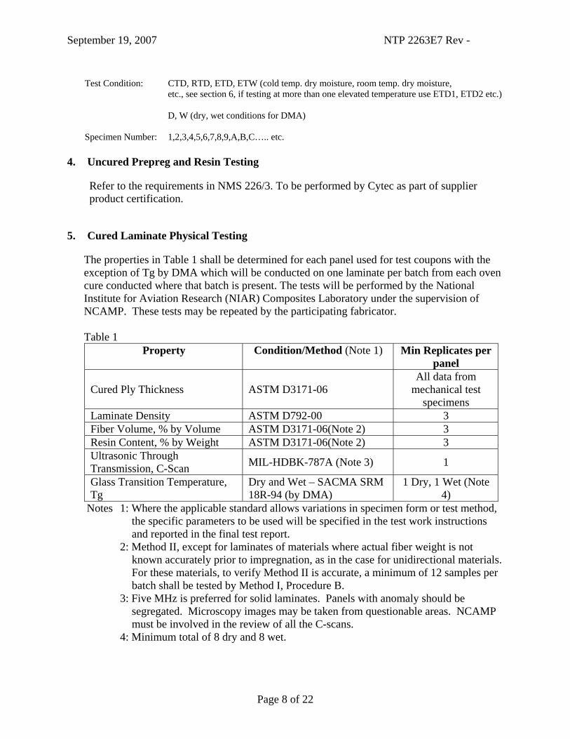
The properties in Table 1 shall be determined for each panel used for test coupons with the exception of Tg by DMA which will be conducted on one laminate per batch from each oven cure conducted where that batch is present. The tests will be performed by the National Institute for Aviation Research (NIAR) Composites Laboratory under the supervision of NCAMP. These tests may be repeated by the participating fabricator. Table 1
Property Condition/Method (Note 1) Min Replicates per panel
Cured Ply Thickness ASTM D3171-06 All data from
mechanical test specimens
Laminate Density ASTM D792-00 3 Fiber Volume, % by Volume ASTM D3171-06(Note 2) 3 Resin Content, % by Weight ASTM D3171-06(Note 2) 3 Ultrasonic Through Transmission, C-Scan MIL-HDBK-787A (Note 3) 1
Glass Transition Temperature, Tg
Dry and Wet – SACMA SRM 18R-94 (by DMA)
1 Dry, 1 Wet (Note 4)
Notes 1: Where the applicable standard allows variations in specimen form or test method, the specific parameters to be used will be specified in the test work instructions and reported in the final test report.
2: Method II, except for laminates of materials where actual fiber weight is not known accurately prior to impregnation, as in the case for unidirectional materials. For these materials, to verify Method II is accurate, a minimum of 12 samples per batch shall be tested by Method I, Procedure B.
3: Five MHz is preferred for solid laminates. Panels with anomaly should be segregated. Microscopy images may be taken from questionable areas. NCAMP must be involved in the review of all the C-scans.
4: Minimum total of 8 dry and 8 wet.

September 19, 2007 NTP 2263E7 Rev -
Page 9 of 22
6. Cured Lamina and Laminate Mechanical Property Testing
The following tests will be performed by the NIAR Composites Laboratory under the supervision of NCAMP. Specimen dimensions should be taken before moisture conditioning. Test environments are defined as: CTD = -65±5°F, dry RTD = 70±10°F, room temperature dry ETD = 350±5°F dry ETW = 350±5°F, wet (equilibrium moisture content) Elevated temperature level of 350±5°F may be reduced if wet glass transition temperature is not 400°F or higher. The elevated temperature level may be adjusted to approximately 50°F below the measured wet glass transition temperature. All failure modes must be clearly identified. Testing shall achieve appropriate failure modes. Within each test method and test environment, the failure mode shall be evaluated immediately after each test by an FAA ACO engineer or FAA DER. Obvious improper failure modes shall be logged. If a second improper failure mode occurs, testing shall cease until the test setup and test data can be reviewed by the FAA and NCAMP. Retain the samples until data review is complete and the test report is finalized. All tested specimens shall be digitally photographed after each test in order to pictorially document failure modes. Representative photos shall be included in the final report. 6.1 Environmental Conditioning
For dry testing, specimens will be dried at 160°F±5°F for 120 to 130 hours. After drying, specimens should be kept in a desiccator until mechanical testing. Alternatively, the specimens may be left at ambient laboratory condition for a maximum of 14 days until mechanical testing (no drying will be required if specimens are tested within 14 days from the date they were cured). Ambient laboratory condition is defined as 70°F±10°F. Since moisture absorption and desorption rate for BMI is very slow at ambient temperature, there is no requirement to maintain relative humidity levels.

September 19, 2007 NTP 2263E7 Rev -
Page 10 of 22
For wet conditioning, specimens will be dried at 160°F±5°F for 120 to 130 hours before being conditioned to equilibrium at 160°F±5°F and 85% ± 5%. Effective moisture equilibrium is achieved when the average moisture content of the traveler specimen changes by less than 0.05% for three consecutive readings which are 7 ±0.5 days apart and may be expressed by:
0.0005 < WW - W
b
1 - ii
where: Wi = weight at current time Wi – 1 = weight at previous time Wb = baseline weight prior to conditioning
When representative specimens may not be measured to determine the moisture content (due to size, fastener and tab effects), traveler coupons of at least 1” by 1” by specimen thickness and weighing at least 5 grams may be used to establish weight gain measurements. If the specimens or traveler coupons pass the criteria for three consecutive readings which are 7 ±0.5 days apart, the specimens may be kept in the environmental chamber for up to an additional 60 days. Alternatively, the specimens may be removed from the environmental chamber and placed in a sealed plastic bag along with a moist cotton towel for a maximum of 14 days until mechanical testing. Strain-gaged specimens may be removed from the controlled environment for a maximum of 2 hours for application of gages in ambient laboratory conditions.
6.2 Non-ambient Testing
The chamber should be of adequate size that all test fixtures and load frame grips may be contained within the chamber.
For elevated temperature testing, the temperature chamber, test fixture, and grips should be preheated to the specified temperature. Each specimen should be heated to the required test temperature as verified by a thermocouple in direct contact with and taped to the specimen gage section. The heat-up time of the specimen shall not exceed 5 minutes. The test should start 1
02 +− minutes after the specimen has reached the test temperature. During the test, the temperature, as measured on the specimen, shall be within ±5°F of the required test temperature.
For subzero temperature testing, each specimen should be cooled to the required test temperature as verified by a thermocouple in direct contact with and taped to the specimen gage section. The test should start 1
0 5 +− minutes after the specimen has reached the test
temperature. During the test, the temperature, as measured on the specimen, shall be within ±5°F of the required test temperature.
September 19, 2007 NTP 2263E7 Rev -
Page 11 of 22
6.3 Process Definition
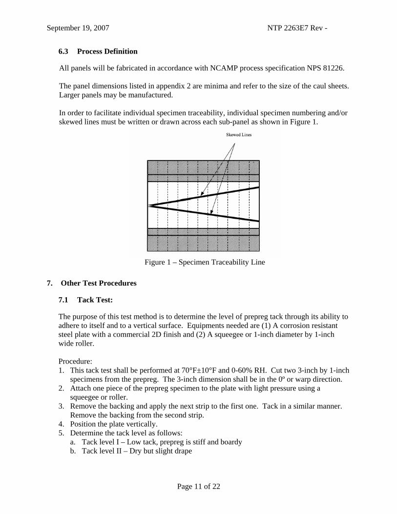
All panels will be fabricated in accordance with NCAMP process specification NPS 81226. The panel dimensions listed in appendix 2 are minima and refer to the size of the caul sheets. Larger panels may be manufactured. In order to facilitate individual specimen traceability, individual specimen numbering and/or skewed lines must be written or drawn across each sub-panel as shown in Figure 1.
Figure 1 – Specimen Traceability Line
7. Other Test Procedures
7.1 Tack Test:
The purpose of this test method is to determine the level of prepreg tack through its ability to adhere to itself and to a vertical surface. Equipments needed are (1) A corrosion resistant steel plate with a commercial 2D finish and (2) A squeegee or 1-inch diameter by 1-inch wide roller. Procedure: 1. This tack test shall be performed at 70°F±10°F and 0-60% RH. Cut two 3-inch by 1-inch
specimens from the prepreg. The 3-inch dimension shall be in the 0º or warp direction. 2. Attach one piece of the prepreg specimen to the plate with light pressure using a
squeegee or roller. 3. Remove the backing and apply the next strip to the first one. Tack in a similar manner.
Remove the backing from the second strip. 4. Position the plate vertically. 5. Determine the tack level as follows:
a. Tack level I – Low tack, prepreg is stiff and boardy b. Tack level II – Dry but slight drape
September 19, 2007 NTP 2263E7 Rev -
Page 12 of 22
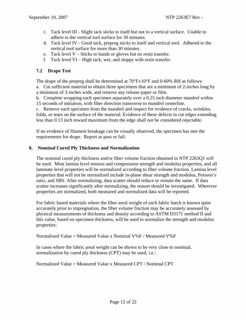
c. Tack level III - Slight tack sticks to itself but not to a vertical surface. Unable to adhere to the vertical tool surface for 30 minutes.
d. Tack level IV - Good tack, prepreg sticks to itself and vertical tool. Adhered to the vertical tool surface for more than 30 minutes.
e. Tack level V – Sticks to hands or gloves but no resin transfer. f. Tack level VI – High tack, wet, and sloppy with resin transfer.
7.2 Drape Test
The drape of the prepreg shall be determined at 70°F±10°F and 0-60% RH as follows: a. Cut sufficient material to obtain three specimens that are a minimum of 2-inches long by a minimum of 3-inches wide, and remove any release paper or film. b. Complete wrapping each specimen separately over a 0.25 inch diameter mandrel within 15 seconds of initiation, with fiber direction transverse to mandrel centerline. c. Remove each specimen from the mandrel and inspect for evidence of cracks, wrinkles, folds, or tears on the surface of the material. Evidence of these defects in cut edges extending less than 0.13 inch inward maximum from the edge shall not be considered rejectable. If no evidence of filament breakage can be visually observed, the specimen has met the requirements for drape. Report as pass or fail.
8. Nominal Cured Ply Thickness and Normalization
The nominal cured ply thickness and/or fiber volume fraction obtained in NTP 2263Q1 will be used. Most lamina level tension and compression strength and modulus properties, and all laminate level properties will be normalized according to fiber volume fraction. Lamina level properties that will not be normalized include in-plane shear strength and modulus, Poisson’s ratio, and SBS. After normalizing, data scatter should reduce or remain the same. If data scatter increases significantly after normalizing, the reason should be investigated. Wherever properties are normalized, both measured and normalized data will be reported. For fabric based materials where the fiber areal weight of each fabric batch is known quite accurately prior to impregnation, the fiber volume fraction may be accurately assessed by physical measurements of thickness and density according to ASTM D3171 method II and this value, based on specimen thickness, will be used to normalize the strength and modulus properties: Normalized Value = Measured Value x Nominal V%F / Measured V%F In cases where the fabric areal weight can be shown to be very close to nominal, normalization by cured ply thickness (CPT) may be used, i.e.: Normalized Value = Measured Value x Measured CPT / Nominal CPT

September 19, 2007 NTP 2263E7 Rev -
Page 13 of 22
9. Mechanical Testing
A single batch of prepreg will be used to demonstrate equivalency. As in the original database tests, each property/test condition will require two separate cure cycles as shown in Figure 2. Table 2 shows the single batch equivalency test matrix. The layup angles 0º, 45º, -45º, and 90º refer to the orientation of the warp direction. The number of plies is chosen to produce a laminate thickness appropriate for the test method in question. This is also called out in appendices 1 and 2. These single batch tests are designed to demonstrate equivalency with the three batch data for purposes described in MIL-HDBK-17-1F Section 8.4.1 and DOT/FAA/AR-03/19 Section 6. Specifically, equivalency demonstration may allow the panel manufacturer to utilize the common database of material properties and basis values. For each property and test condition, the statistical test methods of reference 2 will be used to analyze the data.
BATCH 1
PANEL 2
4 spec.
PANEL 1
4 spec.
8 SPECIMENS TOTAL
MaterialBatch
PanelManufacturing & Independent Cure Process
Number of Specimens
Required perTest Method &Environment
Figure 2 Specimen Selection Methodology and Processing Traceability per Test Method and
Environmental Condition Used to Establish Material Equivalence.
September 19, 2007 NTP 2263E7 Rev -
Page 14 of 22
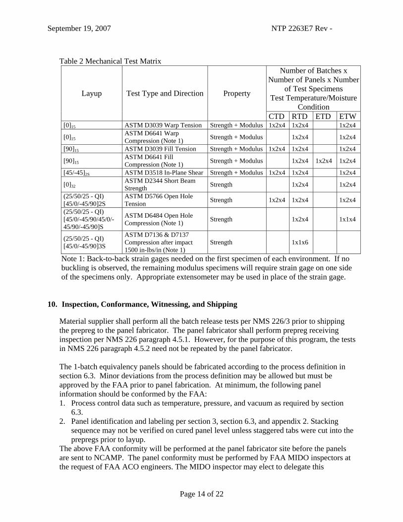
Table 2 Mechanical Test Matrix
Number of Batches x Number of Panels x Number
of Test Specimens Test Temperature/Moisture
Condition
Layup Test Type and Direction Property
CTD RTD ETD ETW [0]15 ASTM D3039 Warp Tension Strength + Modulus 1x2x4 1x2x4 1x2x4
[0]15 ASTM D6641 Warp Compression (Note 1) Strength + Modulus 1x2x4 1x2x4
[90]15 ASTM D3039 Fill Tension Strength + Modulus 1x2x4 1x2x4 1x2x4
[90]15 ASTM D6641 Fill Compression (Note 1) Strength + Modulus 1x2x4 1x2x4 1x2x4
[45/-45]2S ASTM D3518 In-Plane Shear Strength + Modulus 1x2x4 1x2x4 1x2x4
[0]32 ASTM D2344 Short Beam Strength Strength 1x2x4 1x2x4
(25/50/25 - QI) [45/0/-45/90]2S
ASTM D5766 Open Hole Tension Strength 1x2x4 1x2x4 1x2x4
(25/50/25 - QI) [45/0/-45/90/45/0/-45/90/-45/90]S
ASTM D6484 Open Hole Compression (Note 1) Strength 1x2x4 1x1x4
(25/50/25 - QI) [45/0/-45/90]3S
ASTM D7136 & D7137 Compression after impact 1500 in-lbs/in (Note 1)
Strength 1x1x6
Note 1: Back-to-back strain gages needed on the first specimen of each environment. If no buckling is observed, the remaining modulus specimens will require strain gage on one side of the specimens only. Appropriate extensometer may be used in place of the strain gage.
10. Inspection, Conformance, Witnessing, and Shipping
Material supplier shall perform all the batch release tests per NMS 226/3 prior to shipping the prepreg to the panel fabricator. The panel fabricator shall perform prepreg receiving inspection per NMS 226 paragraph 4.5.1. However, for the purpose of this program, the tests in NMS 226 paragraph 4.5.2 need not be repeated by the panel fabricator. The 1-batch equivalency panels should be fabricated according to the process definition in section 6.3. Minor deviations from the process definition may be allowed but must be approved by the FAA prior to panel fabrication. At minimum, the following panel information should be conformed by the FAA: 1. Process control data such as temperature, pressure, and vacuum as required by section
6.3. 2. Panel identification and labeling per section 3, section 6.3, and appendix 2. Stacking
sequence may not be verified on cured panel level unless staggered tabs were cut into the prepregs prior to layup.
The above FAA conformity will be performed at the panel fabricator site before the panels are sent to NCAMP. The panel conformity must be performed by FAA MIDO inspectors at the request of FAA ACO engineers. The MIDO inspector may elect to delegate this

September 19, 2007 NTP 2263E7 Rev -
Page 15 of 22
responsibility to a DMIR or DAR. In the case that the panels are fabricated in a foreign country, the FAA will request the civil aviation authority of that country to perform the inspections on the FAA’s behalf. The civil aviation authority may delegate the conformity to the panel fabricator or an authorized representative in accordance with the country’s regulations. Prior to shipping the panels, verify the following: 1. The appropriate sections in the “Panel Data” sheet of
PMC_Data_Collection_Template.xls file has been completed. 2. In-process monitoring data such as part temperature, autoclave temperature, autoclave
pressure, autoclave vacuum, and part vacuum readings, preferably in electronic format, is included
3. FAA conformity record (if needed), is included. 4. The panel names match the names listed in Appendix 2 of the test plan Send the panels along with the in-process monitoring data and FAA conformity records to: Wichita State University NIAR NCAMP, Attn: Yeow Ng 1845 Fairmount Ave. Wichita, KS 67260-0093 USA Tel: 316-978-5212 Prior to testing, test specimen conformity must be performed by MIDO inspectors at the request of ACO engineers. The MIDO inspector may elect to delegate this responsibility to a DMIR or DAR. Testing must be witnessed by the FAA (except for those in section 4). Witnessing can be performed by ACO engineers, or they may delegate this responsibility to a DER, MIDO inspector, DMIR or DAR. Mechanical testing will be carried out at the National Institute for Aviation Research, Wichita State University. The test setup and procedures in section 4 will be reviewed by NCAMP IAB and NCAMP staff during facility audit.
11. Data Reduction and Reporting
The data generated in this test plan will be statistically compared with the data generated from the original qualification program (NTP 2263Q1) using the methodology of reference 2. Both the actual Coefficient of Variation (CV) and modified CV will be used in the statistical tests. The modified CV will be calculated as follows: 1) If the measured CV at a given test condition is 0% to 4%, use an assumed CV of 6% or the pooled CV, whichever is greater. 2) If the measured CV at a given test condition is between 4% and 8%, use an assumed CV = 0.5*(measured individual CV) + 4% or the pooled CV, whichever is greater. 3) If the measured CV at a given test condition is 8% to 10%, use the measured CV or the pooled CV, whichever is greater.

September 19, 2007 NTP 2263E7 Rev -
Page 16 of 22
4) If the measured CV at a given test condition is 10% or greater, question the data. And for setting specification requirement use a maximum CV of 10%. If deemed appropriate, the single batch equivalency data may be pooled into the three batch qualification data to generate material properties that are more representative of the overall material performance.
12. Specifications
All materials will be manufactured to Cytec prepreg Process Control Document 21970157 latest revision using the nominal parameters given in section 1 above, and in accordance with NMS 226/3.
13. References
Reference 1. DOT/FAA/AR-02/109 Recommended criteria and Guidelines for the Development of a Material Specification for Carbon/Epoxy Prepregs to be used on FAA Certified Structures. Reference 2. DOT/FAA/AR-03/19 Material Qualification and Equivalency for Polymer Matrix Composite Material Systems. Reference 3. MIL-HDBK-17 Rev. F, Composite Materials Handbook Reference 4. DOT/FAA/AR-02/110 Recommendations and Guidelines for the Development of a Process Specification for the Fabrication of Carbon Fiber Reinforced Epoxy Composite Structures.
14. Revisions
Revision Date Description - 9/19/2007 Initial Release

Page 17 of 22
Appendix 1
Cytec Cycom 5250-5 T650 3K Plain Weave Fabric Prepreg Equivalency Tests
Prepreg Batch A B C 3K70PW Prepreg
Cure Cycle Property
Orientation Cond.
C1 C2 C1 C2 C1 C2 Warp Tension Properties (50/0/50) CTD 4 4
Strength & Modulus (extensometer OR CEA-00-125UT-350 OR CEA-XX-250UW-350) [0]15 RTD 4 4
ASTM D 3039 ETD 1.00 x 10.00 (0°) in. (tabs optional) ETW 4 4
Warp Compression Properties (50/0/50) CTD
Strength & Modulus (extensometer OR CEA-XX-125UT-350) [0]15 RTD 4 4 ASTM D 6641 ETD
0.50 x 5.50 (0°) in. ETW 4 4 Fill Tension Properties (50/0/50) CTD 4 4
Strength & Modulus (extensometer OR CEA-XX-250UW-350) [90]15 RTD 4 4 ASTM D 3039 ETD
1.00 x 10.00 (90°) in. (tabs optional) ETW 4 4 Fill Compression Properties (50/0/50) CTD
Strength & Modulus (extensometer OR CEA-XX-125UT-350) [90]15 RTD 4 4 ASTM D 6641 ETD 4 4
0.50 x 5.50 (90°) in. ETW 4 4 In-Plane Shear Properties (0/100/0) CTD 4 4
Strength & Modulus (extensometer OR one CEA-00-125UT-350 OR two CEA-XX-250UW-350) [45/-45]2S RTD 4 4

Page 18 of 22
ASTM D 3518 ETD 1.00 x 10.00 (0°) in. (tabs optional) ETW 4 4
Short Beam Strength Properties (50/0/50) CTD
Strength [0]32 RTD 4 4 ASTM D 2344 ETD
0.50 x 1.50 (0°) in. ETW 4 4 Open Hole Tension Properties 1 (25/50/25 - QI) CTD 4 4
Strength [45/0/-45/90]2S RTD 4 4 ASTM D 5766 ETD
1.5 x 12.0 (0°) in., 0.25 in. dia hole ETW 4 4 Open Hole Compression Properties 1 (25/50/25 - QI) CTD
Strength [45/0/-45/90/45/0/-45/90/-45/90]S RTD 4 4 ASTM D 6484 ETD
1.5 x 12.0 (0°) in., 0.25 in. dia hole ETW 4 4 Compression Strength after Impact 1 (25/50/25 - QI) CTD
Strength [45/0/-45/90]3S RTD 6 ASTM D7136 & D7137 ETD
4.0 x 6.0 (0°) in. ETW 1500 in-lb/in

Page 19 of 22
Appendix 2
Cytec Cycom 5250-5 T650 3K Plain Weave Fabric Prepreg Equivalency Panels
3K PW carbon CPT= 0.00795" approx Length Width
ID Table Batch (%0/%45/%90) Layup #
Plies Qty inch direction inch direction NTP2263E7-CYT-C23-BCI- WT-A-C1-1 2 A (50/0/50) [0]15 15 1 12 along 90º 24 along 0º NTP2263E7-CYT-C23-BCI- WT-A-C2-1 2 A (50/0/50) [0]15 15 1 12 along 90º 24 along 0º NTP2263E7-CYT-C23-BCI- WC-A-C1-1 2 A (50/0/50) [0]15 15 1 12 along 90º 13 along 0º NTP2263E7-CYT-C23-BCI- WC-A-C2-1 2 A (50/0/50) [0]15 15 1 12 along 90º 13 along 0º NTP2263E7-CYT-C23-BCI- FT-A-C1-1 2 A (50/0/50) [90]15 15 1 12 along 90º 24 along 0º NTP2263E7-CYT-C23-BCI- FT-A-C2-1 2 A (50/0/50) [90]15 15 1 12 along 90º 24 along 0º NTP2263E7-CYT-C23-BCI- FC-A-C1-1 2 A (50/0/50) [90]15 15 1 12 along 90º 13 along 0º NTP2263E7-CYT-C23-BCI- FC-A-C2-1 2 A (50/0/50) [90]15 15 1 12 along 90º 13 along 0º NTP2263E7-CYT-C23-BCI- IPS-A-C1-1 2 A (0/100/0) [45/-45]2S 8 1 12 any 24 any NTP2263E7-CYT-C23-BCI- IPS-A-C2-1 2 A (0/100/0) [45/-45]2S 8 1 12 any 24 any NTP2263E7-CYT-C23-BCI- SBS-A-C1-1 2 A (50/0/50) [0]32 32 1 6 along 90º 8 along 0º NTP2263E7-CYT-C23-BCI- SBS-A-C2-1 2 A (50/0/50) [0]32 32 1 6 along 90º 8 along 0º NTP2263E7-CYT-C23-BCI- OHT1-A-C1-1 2 A ( 25/50/25 - QI) [45/0/-45/90]2S 16 1 14 along 90º 28 along 0º NTP2263E7-CYT-C23-BCI- OHT1-A-C2-1 2 A ( 25/50/25 - QI) [45/0/-45/90]2S 16 1 14 along 90º 28 along 0º
NTP2263E7-CYT-C23-BCI- OHC1-A-C1-1 2 A ( 25/50/25 - QI) [45/0/-45/90/45/0/-45/90/-
45/90]S 20 1 14 along 90º 28 along 0º
NTP2263E7-CYT-C23-BCI- OHC1-A-C2-1 2 A ( 25/50/25 - QI) [45/0/-45/90/45/0/-45/90/-
45/90]S 20 1 14 along 90º 28 along 0º NTP2263E7-CYT-C23-BCI- CAI1-A-C1-1 2 A ( 25/50/25 - QI) [45/0/-45/90]3S 24 1 14 along 90º 28 along 0º

Page 20 of 22
Appendix 3
(Below are sample pictures from NCAMP’s “PMC_Data_Collection_Template.xls”. Please use the actual templates to record the information)
General Material Description (To be completed by the material supplier)
COMPOSITE MATERIALDATA COLLECTION TEMPLATE
Required EntryGENERAL MATERIAL DESCRIPTION Required Entry if ApplicableTO BE COMPLETED BY MATERIAL SUPPLIER Optional
COMPOSITE Unit or FormatComposite Common NameComposite Source (Supplier and/or supplier location)Composite Product Name (Supplier's catalog name)Composite Material Form – General < select from pull-downReinforcement Form or Fabric Weave Style < select from pull-downNominal Fiber Areal Weight (of tape, fabric, or preform) g/m2
Nominal Resin Solids Content (of prepreg) wt. %Composite Specification NumberComposite Specification Dash NumberScrim Material Common NameScrim Weave Style < select from pull-downScrim Source (Supplier)Nominal Cured Ply Thickness Related to I9 inch
MATRIXMatrix Type < select from pull-downMatrix Common NameMatrix Source (Supplier)Matrix Nominal Density (cured) g/cm3
Matrix Specification Number
REINFORCEMENTFiber Type < select from pull-downFiber Common NameFiber SourceFiber Nominal Density g/cm3
Fiber Length (for discontinuous reinforcement) inchTow Twist (0 = no twist) turns/inchFiber Surface Treatment (Yes or No) < select from pull-downFiber Sizing/Finish TypeFiber Sizing/Finish NameSizing/Finish Content, Nominal wt. %Filament Count per Tow ##kTow Denier denierNominal Tow Yield (forms used as tow) linear ft./lb.Fiber Specification Number
PREFORM (Including Fabrics)Preform Source (Weaver, Braider, or Stitcher)Tackifier TypeTackifier Common NameTackifier SourceYarn Count, Nominal (Warp x Fill for Fabrics) yarns/inchStitching Count stitches/inchStitching Yarn Row Spacing inchPreform Specification NumberTackifier Specification Number
NOTESMaterial Description Note or Comment
ASTM E1434Item No.
Page 21 of 22
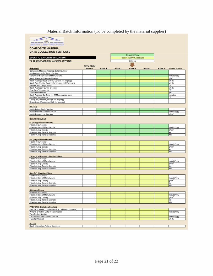
Material Batch Information (To be completed by the material supplier)
COMPOSITE MATERIALDATA COLLECTION TEMPLATE
SPECIFIC BATCH INFORMATIONTO BE COMPLETED BY MATERIAL SUPPLIER
PREPREG Batch 1 Batch 2 Batch 3 Batch 4 Batch 5 Unit or FormatComposite Material (Prepreg) Batch Number(assign number for liquid molding)Composite Batch Date of Manufacture mm/dd/yyyyBatch Average Fiber Areal Weight g/m2
Batch Average Resin (solids) Content (of prepreg) wt. %Batch Avg. Volatile Content (of prepreg or RTM resin) wt. %Volatile Test Temperature °FBatch Average Flow (of prepreg) wt. %Flow Test Temperature °FFlow Test Pressure psiBatch Average Gel Time (of RTM or prepreg resin) minutesGel Test Temperature °FTack (Low, Medium, or High for prepreg)Drape (Low, Medium, or High for prepreg)
MATRIXMatrix Lot or Batch NumberMatrix Lot Date of Manufacture mm/dd/yyyyMatrix Density, Lot Average g/cm3
REINFORCEMENT
0° (Warp) Direction FibersFiber Lot Number(s)Fiber Lot Date of Manufacture mm/dd/yyyyFiber Lot Avg. Density g/cm3
Fiber Lot Avg. Tensile Strength ksiFiber Lot Avg. Tensile Modulus Msi
90° (Fill) Direction FibersFiber Lot Number(s)Fiber Lot Date of Manufacture mm/dd/yyyyFiber Lot Avg. Density g/cm3
Fiber Lot Avg. Tensile Strength ksiFiber Lot Avg. Tensile Modulus Msi
Through Thickness Direction FibersFiber Lot Number(s)Fiber Lot Date of Manufacture mm/dd/yyyyFiber Lot Avg. Density g/cm3
Fiber Lot Avg. Tensile Strength ksiFiber Lot Avg. Tensile Modulus Msi
Bias (θ°) Direction FibersFiber Lot Number(s)Fiber Lot Date of Manufacture mm/dd/yyyyFiber Lot Avg. Density g/cm3
Fiber Lot Avg. Tensile Strength ksiFiber Lot Avg. Tensile Modulus Msi
Stitching FibersFiber Lot Number(s)Fiber Lot Date of Manufacture mm/dd/yyyyFiber Lot Avg. Density g/cm3
Fiber Lot Avg. Tensile Strength ksiFiber Lot Avg. Tensile Modulus Msi
PREFORM (Including Fabrics)Preform or Fabric Lot Number (e.g.: weaver lot number)Preform or Fabric Date of Manufacture mm/dd/yyyyTackifier Lot NumberTackifier Lot Date of Manufacture mm/dd/yyyyTackifier Content wt. %
NOTESBatch Information Note or Comment
Required EntryRequired Entry if Applicable
ASTM E1434Item No.
Optional

Page 22 of 22
Test Panel Data (To be completed by the panel fabricator)
COMPOSITE MATERIALDATA COLLECTION TEMPLATE
TEST PANEL (OR SUB-PANEL) DATASubpanels must be identified to indicate the parent panel
PANEL DESCRIPTION (TO BE COMPLETED BY PANEL FABRICATOR) Unit or Format Panel 1 Panel 2 Panel 3 PanePanel or Sub-panel Identification Number(used for the consolidated and fully processed panel)Panel Description (type of test for which the panel is to be used)Panel FabricatorComposite Material Batch NumberNumber of Layers (plies) I7Layup Stacking Sequence CMH-17 format Related to H7Composite Material Lot Number (subset of batch)Composite Material Roll Number
PANEL PROCESSING (TO BE COMPLETED BY PANEL FABRICATOR)Lay-up Method select from pull-down >Type of curing or final consolidation process select from pull-down >Autoclave, Oven, or Press IDHeating Rate to Cure Temperature °F/minuteCure Temperature °FCure Pressure (enter 0 for vacuum only) psigCure Time minutesCure Vacuum Maintained Throughout Cure? No or YesCooling Rate After Cure °F/minutePanel Removal Tool Temperature °FCure Vacuum Vent Pressure psigPostcure Temperature °FPostcure Time minutesRTM Vacuum Used? (Yes or No) No or YesRTM/VARTM Resin Temperature at Injection °FRTM/VARTM Preform Degas Procedure Text or ReferenceRTM/VARTM Preform Temperature at Insertion °FRTM/VARTM Tool Temperature Prior to Injection °FRTM/VARTM Resin Injection Rate lb./min. or ml/min.
Required EntryRequired Entry if Applicable
If Applicable to All Panels on this Sheet, Enter for Panel 1 Only and Check Here ASTM E1434
Item No.
Optional
Test Panel Data, continued (To be completed by the testing lab) SECONDARY PANEL OPERATIONS (TO BE COMPLETED BY TESTING LAB)Bonded Tab (doubler) Material I48Bonded Tab (doubler) Layup (stacking sequence) CMH-17 format I50Bonded Tab (doubler) Nominal Thickness inch I51Bonded Tab (doubler) Bevel Angle degrees I52Bonded Tab (doubler) Nominal Length inch I53Bonded Tab (doubler) Bonding Adhesive I49Bonded Tab (doubler) Bond Cycle Temperature °F I54Bonded Tab (doubler) Bond Cycle Time minutes I55Bonded Tab (doubler) Bond Cycle Pressure psiType of Equipment Used for Bonding Tabs select from pull-down >Are Tabs Bonded to Individual Specimens or to Entire Panel? select from pull-down >Sandwich Panel Core Common Name I26Sandwich Panel Core Material Type select from pull-down > I27Sandwich Panel Core Material I28Sandwich Panel Core Material Manufacturer I29Sandwich Panel Core Material Lot Number I30Nominal Sandwich Core Cell Size (for honeycomb hexcore) inch I31Nominal Sandwich Core Cell Count (for honeycomb OX or flexible core) cells per inch I31Nominal Sandwich Core Density lb./ft.3 I32Nominal Sandwich Core Thickness inchNon-test Sandwich Face MaterialNon-test Sandwich Face Nominal Thickness inchSandwich Bonding Adhesive Common Name I34Sandwich Bonding Adhesive Manufacturer I36Sandwich Bonding Adhesive Lot Number I37Sandwich Bonding Adhesive Date of Manufacture mm/dd/yyyy I38Sandwich Secondary Bond Cycle Time/Temp./Pressure
PANEL PROPERTIES (Prior to Secondary Operations) (TO BE COMPLETED BY TESTING LAB)Panel Thickness (panel average) inchPanel Density g/cm3
Panel Density Test MethodPanel Fiber Volume (panel average) vol.% M7Panel Fiber Volume Test MethodPanel Dry Glass Transition Temperature °FPanel Wet Glass Transition Temperature °FPanel Glass Transition Test MethodPanel Void Content vol.%Panel Void Content Test Method
NOTESPanel Data Note or Comment
Additional reporting requirements are related to testing procedures and are to be
completed by the testing labs. The templates may be found in NCAMP’s “PMC_Data_Collection_Template.xls”