buoyancy, stability, and ballast 2 cornerstone electronics ... · cornerstone electronics...
TRANSCRIPT

1
Buoyancy, Stability, and Ballast 2 Cornerstone Electronics Technology and Robotics III
(Notes primarily from “Underwater Robotics – Science Design and Fabrication”, an excellent book for the design, fabrication, and operation of Remotely Operated Vehicles ROVs)
Administration:
o Prayer Trimming a Vehicle:
o Pitch and Roll: Pitch: The rise and fall of the front of a vehicle. The angle of the pitch is
positive if the front is inclined up and negative if the nose is tilted down. See Figure 1.
Figure 1: Level Pitch Positive Pitch Angle Negative Pitch Angle
Trim: The rotation of a vehicle from side to side. See Figure 2.
Figure 2: No Roll Front View Right Roll Front View Left Roll

2
o Trimming Pitch and Roll: Trimming a vehicle involves adjusting the buoyancy, pitch, and roll.
Buoyancy is trimmed by adding or subtracting weights or floats. Trimming pitch and roll is fine tuned by reorganizing the placement of the weights and floats already on the vehicle or by adding weight and floatation that are in balance. Shifting the weights or floats determines the center of gravity (CG) and the center of buoyancy (CB) of a vehicle respectfully.
When the buoyancy, pitch and roll are set to the desired position, the vehicle is said to be “in trim”.
Moving the vehicle’s weight forward will shift the center of gravity forward.
Similarly, moving the vehicle’s floats forward will shift the center of buoyancy forward.
Trimming is two a step procedure. During the design process, make sure that:
o The vehicle weight equals the vehicle’s buoyant force o The weight and floatation components are positioned such
that the center of gravity is directly below the center of buoyancy
When testing in water: o Add, remove, or shift adjustment weights to compensate
for unwanted sinking, floating, or tilting. As discussed in Lesson 9, it is a good idea to have a bolt (trim post) for
washers at each corner of the vehicle for easy last minute trimming. See Figure 3 below.
Figure 3: Trim Post with Stainless Steel Washer Weights

3
If the vehicle’s pitch and roll have been adjusted then its orientation is set. However, if buoyancy is still an issue, the CG of the added weights should be aligned directly below the vehicle’s CG and the CB of the additional floatation should be attached above the vehicle’s CB. Refer to Figures 4a and 4b. Otherwise, the vehicle’s orientation will be thrown out of its set position.
Figure 4a: ROV with Orientation Set Figure 4b: Adding Weight Without Affecting the Orientation
Figure 4c: Adding Floatation without Affecting Orientation

4
If you need to adjust the vehicle’s orientation without affecting the buoyancy, there are two options.
Relocate the weight and/or the floatation already on the vehicle to move the CG and/or CB; see Figures 5.
Figure 5: Maintain Buoyancy by Relocating Weight and Floatation Already on the ROV
You can add additional weight and floatation, but they must be in balance, i.e., the additional weight must equal the buoyant force of the additional floatation. See Figure 6.
Figure 6: To Maintain Buoyancy, the Added Weight Must Balance the Added Floatation

5
Stability: The tendency for a vehicle to return to the upright position when tipped or flipped by a disturbance.
o Stability Under water: Definition of BG: BG is the distance between the center of gravity (CG)
and the center if buoyancy (CB). See Figure 7.
Figure 7: BG – the Distance between CG and CB
The larger the BG, the more stable the vehicle is in water. Recall that a couple consists of two equal and opposite forces acting
upon a body whose parallel lines of force do not coincide (not collinear). The moment of the couple (or torque) is measured by the product of the magnitude of either force and the perpendicular distance d between the lines of the two forces.
Figure 8: A Couple and the Corresponding Torque
6
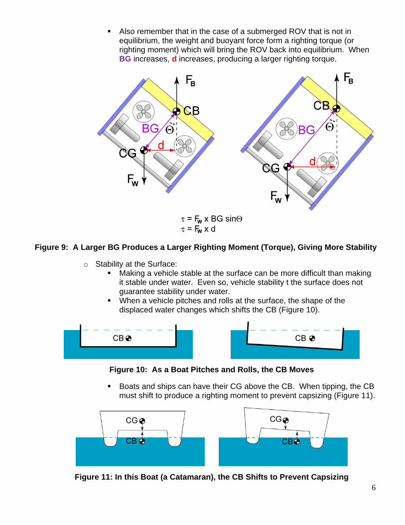
Also remember that in the case of a submerged ROV that is not in equilibrium, the weight and buoyant force form a righting torque (or righting moment) which will bring the ROV back into equilibrium. When BG increases, d increases, producing a larger righting torque.
Figure 9: A Larger BG Produces a Larger Righting Moment (Torque), Giving More Stability
o Stability at the Surface: Making a vehicle stable at the surface can be more difficult than making
it stable under water. Even so, vehicle stability t the surface does not guarantee stability under water.
When a vehicle pitches and rolls at the surface, the shape of the displaced water changes which shifts the CB (Figure 10).
Figure 10: As a Boat Pitches and Rolls, the CB Moves
Boats and ships can have their CG above the CB. When tipping, the CB must shift to produce a righting moment to prevent capsizing (Figure 11).
Figure 11: In this Boat (a Catamaran), the CB Shifts to Prevent Capsizing

7
o Shifting Weights and Loss of Stability: A shift in the CB or CG in an underwater vehicle can potentially lead to
unwanted results. Secure all components to the frame.
Figure 12: A Shifting Battery Creates an Unwanted Equilibrium
Shifting fluids in an onboard container or tank can also move the CG producing an undesirable equilibrium. This is called the free surface effect.
Figure 13: A Displacement of the Fluid in the Onboard Container Shifts the CG

8
By adding baffles inside the tank, the free surface effect is minimized.
Figure 14: There Can Be a Substantial Shift in the CG in a Tank without Baffles
Figure 15: Adding Baffles Limits the Movement of the Fluid Weight, Keeping the CG More Stable
Another method to limit the free surface effect is to use spherical tanks.
Figure 16: Spherical Tanks Minimize the Free Surface Effect with Their Uniform Interior Shape

9
Ballast Systems: o Ballasting: The practice of adding, removing, or relocating weight or floatation
on an underwater vehicle to correct its buoyancy and pitch and roll. o Air under water:
Air and other gases compress relatively easily under water compared to liquids and solids.
As an example, if you were to fill one plastic bag with 1 liter of air and another plastic bag with 1 liter of water and then submerge both to a depth of 1,000 meters, the air and the water would compress to 1% and 99.5% of their original volumes respectfully.
Boyle’s Law: An ideal gas is a gas whose pressure P, volume V, and
temperature T are related by the ideal gas law:
PV = nRT,
Where: P = Absolute pressure of a gas V = Volume of the gas
n = The number of moles of the gas R = The ideal gas constant T = Absolute temperature
Air behaves much like an ideal gas.
For simple underwater vehicle projects, the amount of air within an onboard container remains fixed and the expanse of the water will keep the temperature of the contained air constant. Under these conditions, n, R, and T are constants and the ideal gas law simplifies to Boyle’s Law:
PV = k
Where: P = Absolute pressure of a gas V = Volume of the gas
k = A constant value representative of the pressure and volume of the system
Boyle's law is used to predict the result of introducing a change, in volume and pressure only, to the initial state of a fixed quantity of gas. The before and after volumes and pressures of the fixed amount of gas, where the before and after temperatures are the same (heating or cooling will be required to meet this condition), are related by the equation:
P1V1 = P2V2

10
For example, Figure 17 details what happens if 1 liter air is taken under water in an open beaker:
Figure 17: 1 Liter Beaker of Air Conforming to Boyle’s Law under Water P1V1 = P2V2 = P3V3 = P4V4 = P5V5
PV = 1 atm x 1 L = 2 atm x 0.5 L = 3 atm x 0.33 L = 4 atm x 0.25 L = 5 atm x 0.2 L = 1 atm-L
You can see from Figure 17 that the air volume changes more rapidly at shallow depths.
See applet: http://www.grc.nasa.gov/WWW/k-12/airplane/aboyle.html
o Two types of ballast systems – static and active (dynamic) ballast systems o Static ballast system: The underwater vehicle is pre-set to the desired ballast
and left unchanged (static) throughout the mission. Recall that goal for ROVs and AUVs is for the vehicle to be slightly
positive buoyant. In this state, the vehicle requires a small amount of thruster power to ascend and descend. Being slightly positive buoyant allows the vehicle to float to the surface in the event of propulsion failure.
A simple static ballast system on a ROV is effective even at extreme depths.
A ROV ballast system consists of floatation and weights, Floatation:
o A float is a material that has a density which is less than the water environment around the ROV.
o Common examples are stiff foam and waterproof hollow cylinders.
o Pipe insulation or backer rod may work fine at shallow depths, but it can compress at deeper levels.
o If the floatation material compresses, it no longer provides the buoyant force expected. The vehicle may begin to sink uncontrollably to the bottom.

11
o Foam: Deep-diving ROVs normally use syntactic foam for
floatation. Syntactic foam consists of glass microspheres (millions of hollow glass balls) within a matrix of epoxy resin.
Figure 18: Electron Microscopic Image of Syntactic Foam From: http://en.wikipedia.org/wiki/Syntactic_foam
Since the surface area of each sphere is so small, they do not experience a large compressive force, even at full ocean depths. Syntactic foam is very expensive and toxic to cut so it is not usually used by student-built ROVs.
ROV teams normally attach Styrofoam, neoprene rubber, or foam pipe insulation for their ROV floatation. Of these, Styrofoam is recommended since its stiffness resists compression at shallow depths.
Make sure that the foam used is closed-cell foam. The air spaces in open-cell foams absorb water making them less buoyant as they soak up the water.
A simple method to test for closed-cell foam is to blow through the sample. If you can blow air through the foam it probably is open-cell foam.

12
o Plastic Pipe: Air-filled PVC pipe is a common low-cost float used
for student-built ROVs at shallow depths. An over-pressure relief valve must be installed if this type of ballast is used at greater depths since any leak can pressurize the pipe, causing it to explode when surfacing.
Figure 19: Plastic Pipe Ballast with Pipe Ballast Attached to ROV Glued End Caps
o Ceramic and Plastic Spheres:
DeepSea Power & Lights SeaSpheres™ are engineered to be a high performance buoyancy product available for missions to depths greater than 4000 m. SeaSpheres™ are cast from high purity alumina (Al2O3), an incredibly strong and lightweight ceramic. The spheres can be manufactured with varying wall thickness’ in order to tailor their weight and strength to mission requirements. Trawl floats are available to depths of 400 m.
Figure 20: SeaSpheres™ Ceramic Spheres and Trawl Float

13
Weights: o Several individual weights are can be attached to the lower
structure of a ROV to help ballast an underwater vehicle. o Two metals used for weight are lead and steel or iron
pellets. Lead is high density and inexpensive, but has some environmental toxicity. Always wash your hands after handling lead. Steel pellets are low cost and environmentally safe, however they readily rust in saltwater.
o Remember that objects that are enclosed inside a pressure canister only add to the weight and not to the buoyant force. So if possible, add the weight inside a canister to get its full effect.
o Active Ballast Systems: Vehicles equipped with active ballast systems change their ballast during
the underwater mission. Active ballast systems are normally found on sophisticated vehicles,
such as submarines. However, air can be blown into an ROV’s air ballast tank to increase the buoyant force.
See the textbook for a more thorough discussion of active ballast systems.

14
Cornerstone Electronics Technology and Robotics III
Buoyancy, Stability, and Ballast 2 Lab 3 – Trimming a Small Underwater Vehicle
o Purpose: The student trims a submersible for buoyancy and pitch and roll.
o Apparatus and Materials:
1 – ROV Frame from Lesson 5 1 – Pressure Canister from Lesson 8 4 – ¼-20 x 3” Stainless Steel Machine Screws 4 – ¼-20 Stainless Steel Nuts 4 – ¼-20 Stainless Steel Wing Nuts 20 – 1/4" x 1 1/2" Fender Stainless Steel Washers 1 – Closed-Cell Foam Water Tube 6 – 14” Cable Ties (Zip Ties)
o Procedure:
If you haven’t already attached the ¼-20 x 3” machine screw in each bottom side corner of our ROV, do so now. Position each screw next to a vertical post as shown in the photograph below. Use a ¼-20 stainless steel nut to secure the screw to the rail before stacking any of the washers on the screw.
Attach the pressure canister to the top front rail of your ROV using the two zip ties.
Using the closed-cell foam water and the fender washers, trim your ROV for buoyancy and pitch and roll. For buoyancy, have the vehicle barely positively buoyant. With pitch and roll, trim so that the frame is level in both directions.
The ROV will be trimmed again later after all of the components have been securely attached to the ROV.