building construction i project 1 report
TRANSCRIPT

TOPIC PAGE
01 Introduction (BRIDGET TAN) 2 01.1 Introduction to Site 2
02 Site and Safety (AMOS TAN) 7 02.1 Site and Safety 7 02.2 Plants and Machinery 10
03 External Work (BENJAMIN CHENG) 16 03.1 Setting out and Earth Work 16
04 Foundation (NGE JIA CHEN) 21 04.1 Foundation - Reference 21 04.2 Foundation - On Site 23
05 Superstructure 26 05.1 Beam and Column (LEE CZEN SHING) 26 05.2 Slab (KHOR YEN MIN) 30 05.3 Wall (BRIDGET TAN) 34 05.4 Staircase (AIDA JUNITA) 43
06 Doors and Windows 47 06.1 Doors (AIDA JUNITA) 47 06.2 Windows (KHOR YEN MIN) 53
07 Roof (WONG ZHEN FAI) 57 07.1 Roof - Reference 57 07.2 Roof - On Site 59
08 Summary 64 08.1 References 64
1
BRIDGET TAN SU TING
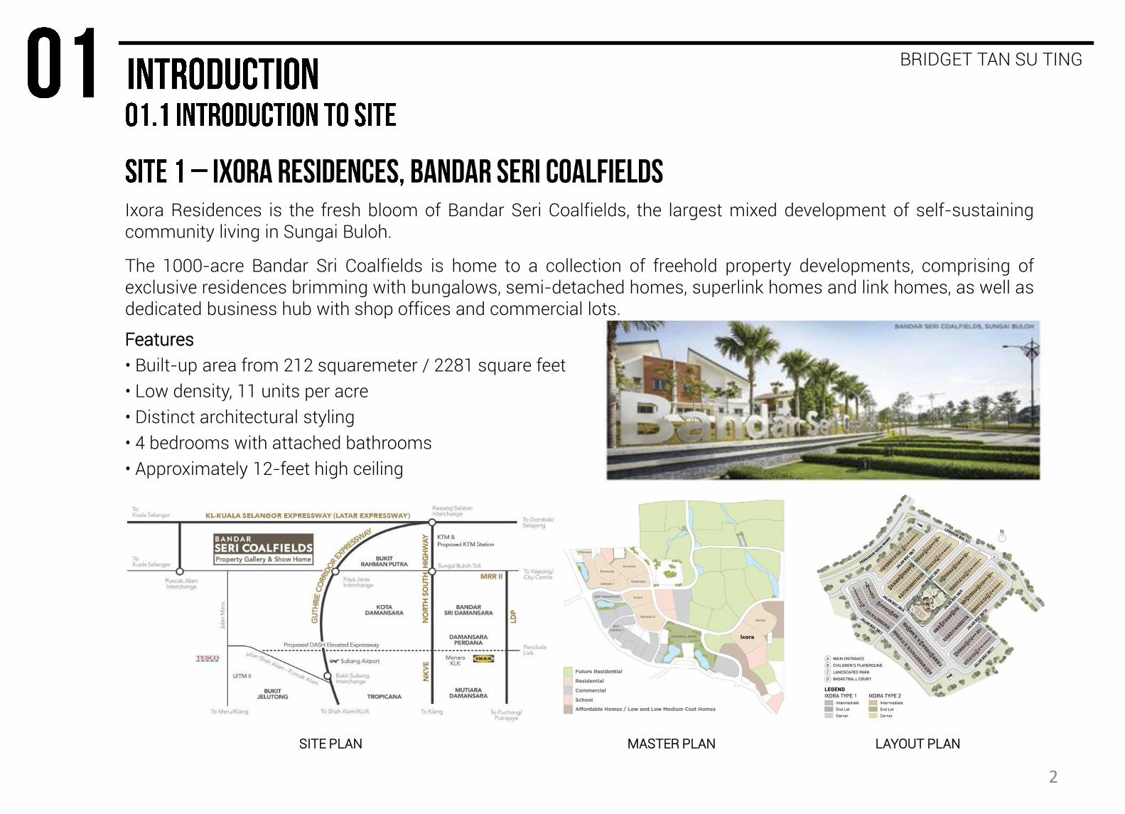
Ixora Residences is the fresh bloom of Bandar Seri Coalfields, the largest mixed development of self-sustaining community living in Sungai Buloh.
The 1000-acre Bandar Sri Coalfields is home to a collection of freehold property developments, comprising of exclusive residences brimming with bungalows, semi-detached homes, superlink homes and link homes, as well as dedicated business hub with shop offices and commercial lots.
Features
• Built-up area from 212 squaremeter / 2281 square feet
• Low density, 11 units per acre
• Distinct architectural styling
• 4 bedrooms with attached bathrooms
• Approximately 12-feet high ceiling
SITE PLAN MASTER PLAN LAYOUT PLAN
2
BRIDGET TAN SU TING
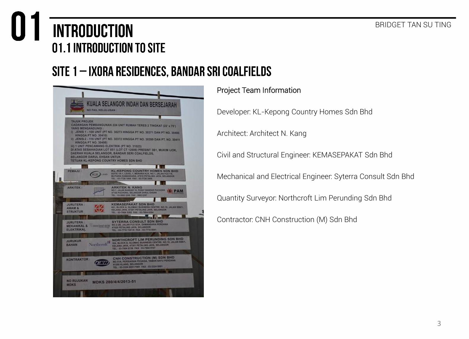
Project Team Information
Developer: KL-Kepong Country Homes Sdn Bhd
Architect: Architect N. Kang
Civil and Structural Engineer: KEMASEPAKAT Sdn Bhd
Mechanical and Electrical Engineer: Syterra Consult Sdn Bhd
Quantity Surveyor: Northcroft Lim Perunding Sdn Bhd
Contractor: CNH Construction (M) Sdn Bhd
3
BRIDGET TAN SU TING
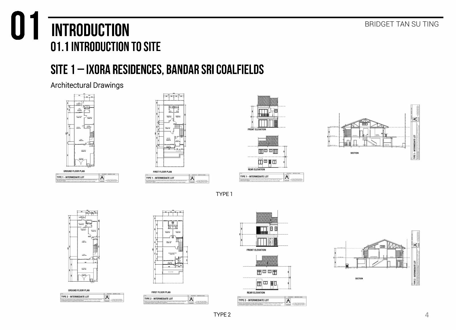
Architectural Drawings
TYPE 1
TYPE 2 4
BRIDGET TAN SU TING
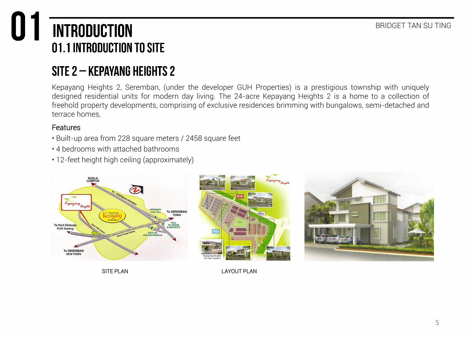
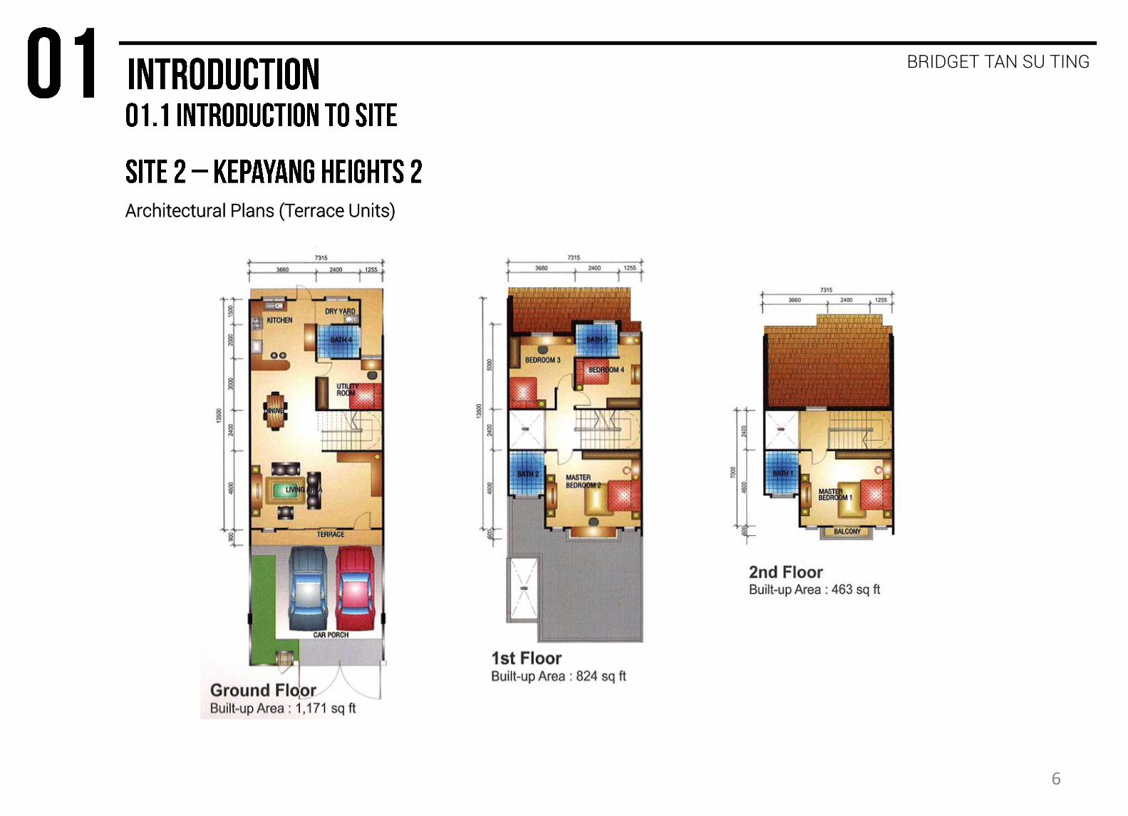
Kepayang Heights 2, Seremban, (under the developer GUH Properties) is a prestigious township with uniquely designed residential units for modern day living. The 24-acre Kepayang Heights 2 is a home to a collection of freehold property developments, comprising of exclusive residences brimming with bungalows, semi-detached and terrace homes,
Features
• Built-up area from 228 square meters / 2458 square feet
• 4 bedrooms with attached bathrooms
• 12-feet height high ceiling (approximately)
SITE PLAN LAYOUT PLAN
5
BRIDGET TAN SU TING
Architectural Plans (Terrace Units)
6
The construction industry is among the most dangerous work sectors in the world. Construction sites create a risk not only for the construction worker, but also for the surrounding public.
AMOS TAN CHI YI
The Department of Occupational Safety and Health (DOSH) is a government body that lays down the regulations to ensure the safety and health of not just workers but also the public.
The regulations are covered by the Occupational Safety and Health Act 1994 (Act 514), the Factories and Machineries Act 1967 (Act 139) and all the regulations made under.
The main contractor of a
worksite that employs 40 or
more persons has to establish
a Safety and Health Committee,
which reviews the conditions of
the site and keeps it under
regulation. Two important
persons in the committee are:
Safety and Health Officer
Any works of construction that
has a total contract price of
RM20,000,000 and over has to
employ a safety and health
officer to oversee the site.
Site Safety Supervisor
A part time position hired for
projects under RM20,000,000,
the supervisor must spend at
least 15 hours a week on site
supervision and promoting safe
conduct of work.
Every developer and contractor has to ensure that all workers are properly informed of the hazards, and also to develop a safety and health manual, and that adequate steps be taken to develop and promote safety and health programmes.
Architects, engineers and other professionals also have a duty not to include anything in a design that would necessitate the use of dangerous structural procedures. Engineers should take into account the safety problems associated with the subsequent maintenance of plant where this would involve hazards.
7

AMOS TAN CHI YI
Every employer has the duty to ensure that each worker is wearing their own personal protective equipment, which consists of:
HELMET
EAR PROTECTION
SAFETY GLASSES
RESPIRATORY EQUIPMENT
REFLECTIVE CLOTHING
SAFETY SHOES
GLOVES
LONG TROUSERS
1. Helmet 2. Gloves 3. Ear protection 4. Safety shoes 5. Safety glasses 6. Reflective clothing 7. Respiratory equipment
Safety Helmet Safety helmets come in different colours, each denoting the wearer’s occupation. White Supervisor (engineer, architect, contractor, etc) Yellow General worker Red Specialist worker (electrician, plumber, etc) Green Safety officers
8
FIGURE 2.1.1: PERSONAL PROTECTIVE EQUIPMENT
AMOS TAN CHI YI
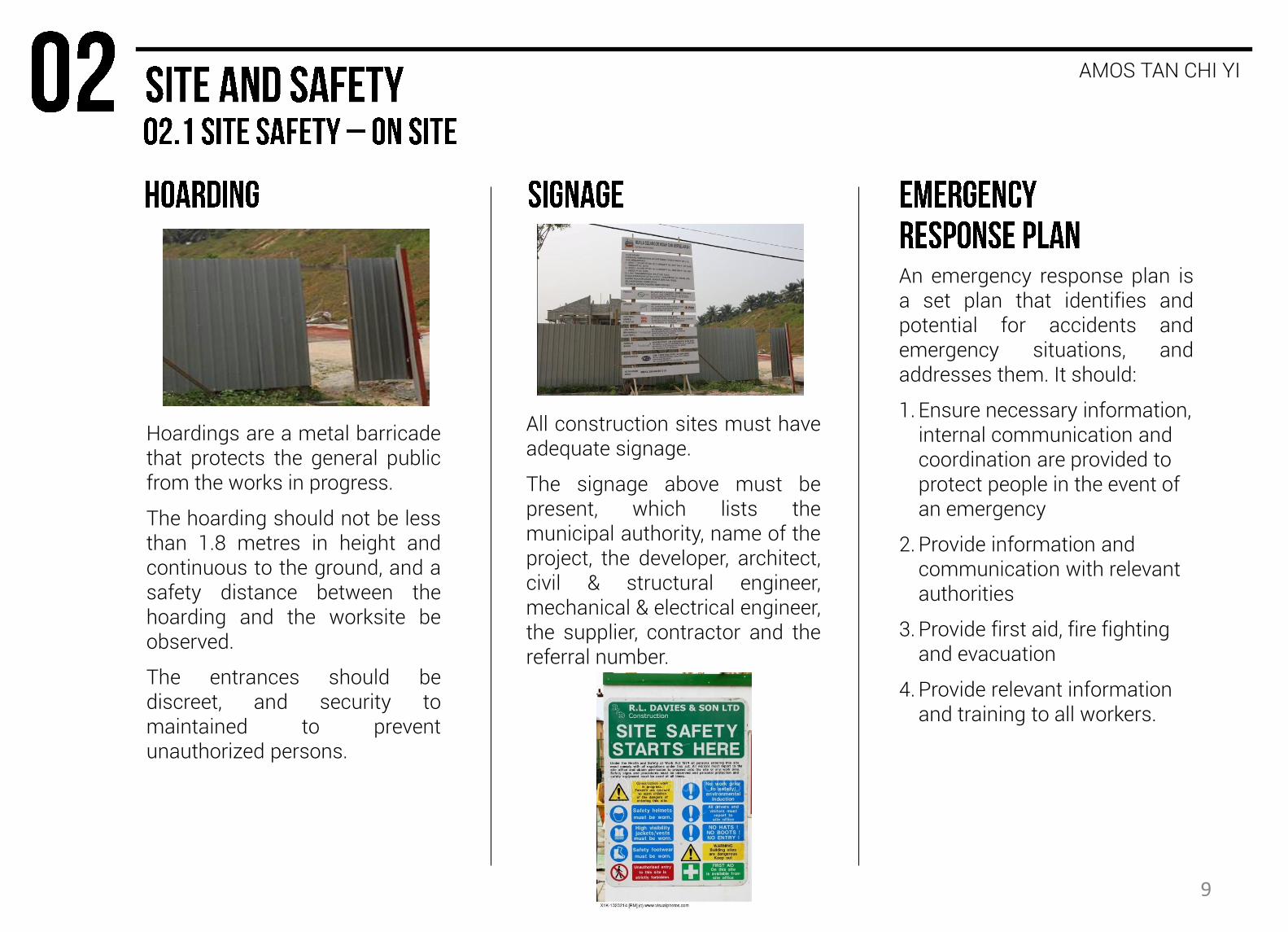
Hoardings are a metal barricade that protects the general public from the works in progress.
The hoarding should not be less than 1.8 metres in height and continuous to the ground, and a safety distance between the hoarding and the worksite be observed.
The entrances should be discreet, and security to maintained to prevent unauthorized persons.
All construction sites must have adequate signage.
The signage above must be present, which lists the municipal authority, name of the project, the developer, architect, civil & structural engineer, mechanical & electrical engineer, the supplier, contractor and the referral number.
An emergency response plan is a set plan that identifies and potential for accidents and emergency situations, and addresses them. It should:
1. Ensure necessary information, internal communication and coordination are provided to protect people in the event of an emergency
2. Provide information and communication with relevant authorities
3. Provide first aid, fire fighting and evacuation
4. Provide relevant information and training to all workers.
9
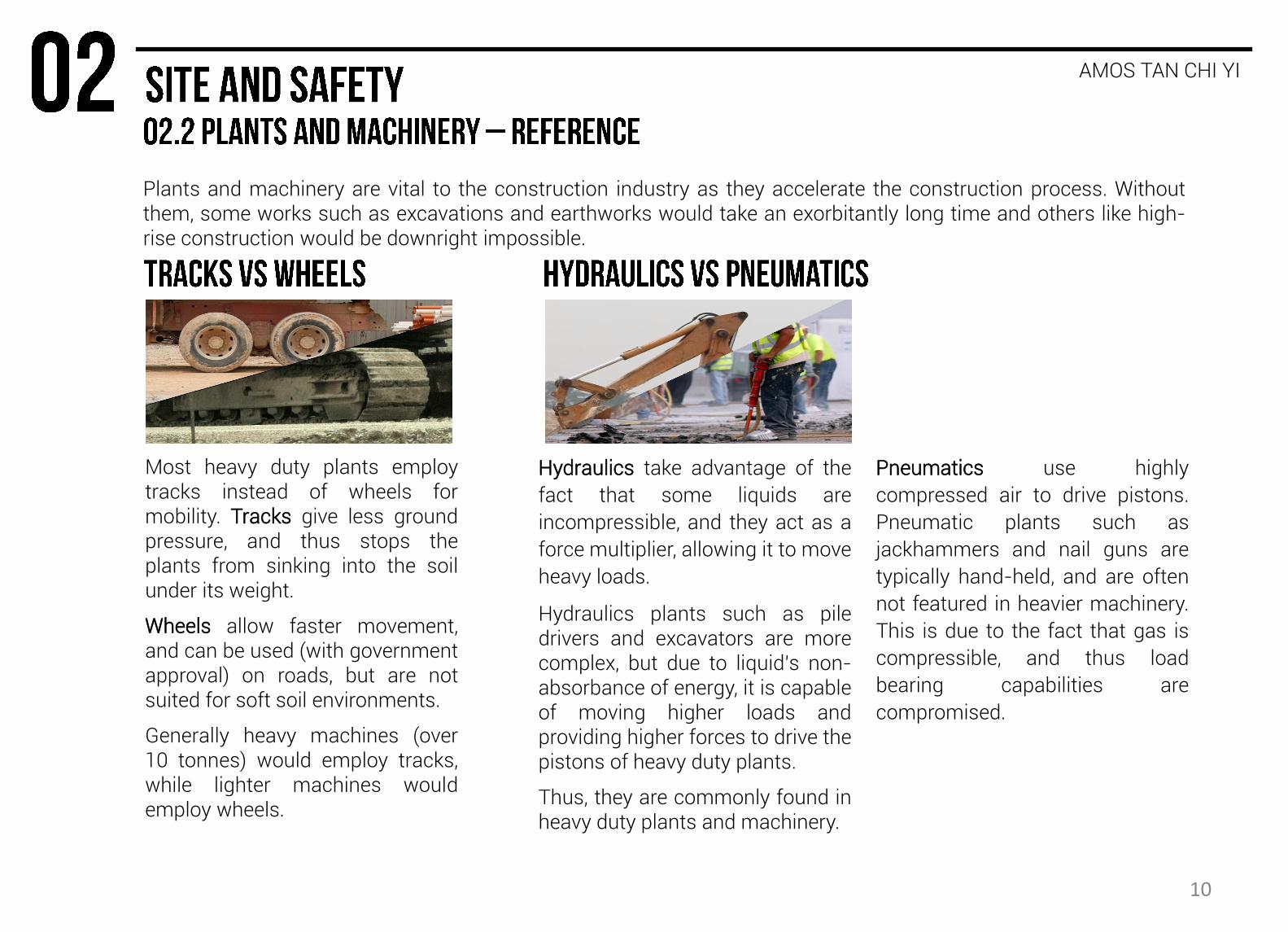
Plants and machinery are vital to the construction industry as they accelerate the construction process. Without them, some works such as excavations and earthworks would take an exorbitantly long time and others like high-rise construction would be downright impossible.
AMOS TAN CHI YI
Most heavy duty plants employ tracks instead of wheels for mobility. Tracks give less ground pressure, and thus stops the plants from sinking into the soil under its weight.
Wheels allow faster movement, and can be used (with government approval) on roads, but are not suited for soft soil environments.
Generally heavy machines (over 10 tonnes) would employ tracks, while lighter machines would employ wheels.
Hydraulics take advantage of the
fact that some liquids are
incompressible, and they act as a
force multiplier, allowing it to move
heavy loads.
Hydraulics plants such as pile drivers and excavators are more complex, but due to liquid’s non-absorbance of energy, it is capable of moving higher loads and providing higher forces to drive the pistons of heavy duty plants.
Thus, they are commonly found in heavy duty plants and machinery.
Pneumatics use highly
compressed air to drive pistons.
Pneumatic plants such as
jackhammers and nail guns are
typically hand-held, and are often
not featured in heavier machinery.
This is due to the fact that gas is
compressible, and thus load
bearing capabilities are
compromised.
10
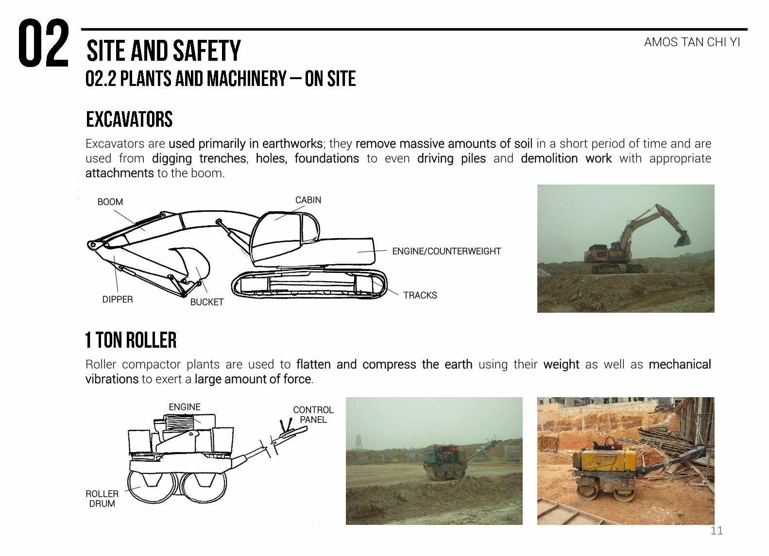
Excavators are used primarily in earthworks; they remove massive amounts of soil in a short period of time and are used from digging trenches, holes, foundations to even driving piles and demolition work with appropriate attachments to the boom.
AMOS TAN CHI YI
CABIN
ENGINE/COUNTERWEIGHT
TRACKS BUCKET DIPPER
BOOM
Roller compactor plants are used to flatten and compress the earth using their weight as well as mechanical vibrations to exert a large amount of force.
ROLLER DRUM
ENGINE CONTROL PANEL
11

Backhoes are excavating plants that combine a dozer blade at the front and a small excavating arm at the back. Backhoe-loaders are general purpose machines, and can be outfitted with a variety of attachments to both ends of the machine to suit the needs of the situation.
AMOS TAN CHI YI
EXCAVATING BUCKET
STABILIZER LEGS
DIESEL ENGINE
LOADER BOOM
DOZER BLADE
CABIN
TEETHED BUCKET
PALLETIZING FORK
SWING BLADE
DRILL & PNEUMATIC
HAMMER
12

Pile drivers are machines that are used to drive piles into the earth during the construction of the foundation. There are many types of pile drivers in use. The hydraulic hammer uses a hydraulic piston to hammer the pile repeatedly until it reaches a suitable depth.
AMOS TAN CHI YI
TOP SHEAVE
PILE
BACK STAY
HYDRAULIC PILE DRIVER
LEADER
CABIN
ENGINE/ COUNTERWEIGHT
13
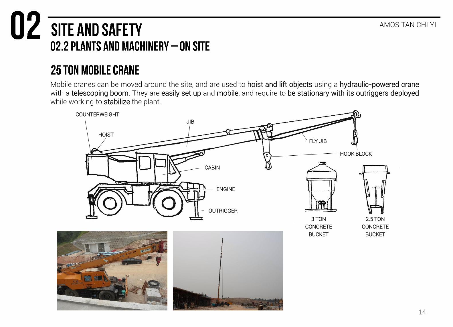
Mobile cranes can be moved around the site, and are used to hoist and lift objects using a hydraulic-powered crane with a telescoping boom. They are easily set up and mobile, and require to be stationary with its outriggers deployed while working to stabilize the plant.
AMOS TAN CHI YI
FLY JIB HOIST
COUNTERWEIGHT
CABIN
OUTRIGGER
JIB
HOOK BLOCK
ENGINE
3 TON
CONCRETE
BUCKET
2.5 TON
CONCRETE
BUCKET
14

Concrete mixer trucks are provided by the concrete supplier to ensure the concrete does not set prematurely while it is being transported to the site. The rotating mixing drum (depending on the model) could hold 34 tonnes, or 10 cubic metres of concrete, and is kept spinning to ensure the concrete does not set.
AMOS TAN CHI YI
Skid loaders are small plants with lift arms and, depending on the attachment, used from excavating small amounts of soil, to transporting heavy materials like bricks on pallets, to drilling holes and even creating trenches.
CABIN
SIDEGUARD
MIXING
DRUM
BRACKET
ROLLER
INLET/OUTLET
CONTROL
SYSTEM
LOADER
BOOM
BUCKET
CABIN
DIESEL
ENGINE
15

BENJAMIN CHENG JIA YEOW
Boundaries are set to differentiate land between different occupiers. Hoarding and the Signage are one of the preliminary infrastructures of the site. Based on this figure, the site boundary can be seen in red.
16

BENJAMIN CHENG JIA YEOW
Site clearance and earthworks are done to ensure that all construction works be carried out smoothly in a conducive environment. This includes the clearance of trees, shrubs, rubbish and other rubbles from the site. Approximately 300mm of topsoil is removed to ensure that the earth is suitable for foundation works, otherwise known as topsoil excavation.
There were other types of excavation done to clear the land before the setting out can begin. Some examples of excavation carried out are earth excavation and rock excavation. This is carried out to reconfigure the topography of the site, also stabilizing slopes in certain areas.
Slopes that are subject to erosion from the runoff of surface water require some means of stabilization. The principle mechanical means of protecting an embankment against erosion is the building of a retaining wall.
Crib walls were used in the site to hold back steep embankments.
FIGURE 3.1.5: AFTER SITE CLEARANCE
FIGURE 3.1.6: CRIB WALL
Topsoil
Excavated face
Granular fill
Precast concrete
Concrete foundation
Drainage
Height in accordance with manufacturer’s requirements.
FIGURE 3.1.7: EXCAVATIONS FIGURE 3.1.8: SKETCH OF CRIB WALL 17

BENJAMIN CHENG JIA YEOW
Profile boards
Base line
Site boundary
Diagonal checks
Main setting out lines
Tripod
Corner post
Plumb rod
Telescopes at right angles
Setting out lines
Nails positioning trench and walls
Pointed posts driven into ground
Position of trench plumbed down
FIGURE 3.1.1: SETTING OUT FIGURE 3.1.2: SETTING OUT
FIGURE3.1.3 – SITESQUARE. Figure 3.1.4: PROFILE BOARD
The first task is to establish a base line from which the whole building can be set out. After the base line has been set out, the main lines of the building are set out and marked with a picket. The setting out lines act as a boundary of which the building must not exceed. Then, a check using a sitesquare is carried out to ensure that right-angles and correct lengths have been established (Figure 3.1.3).
When completed, wooden profile boards are set up to locate the foundation trenches, foundations and walls (Figure 3.1.4). They are required at all trenches and wall intersections. The procedure of earthworks and setting out is important as the final dimensions of the building and the sizes of various rooms depend on this operation.
18
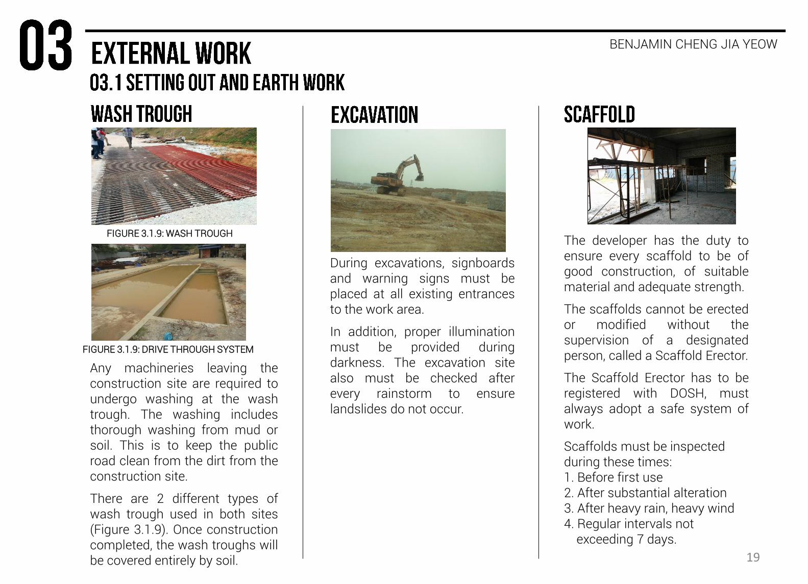
During excavations, signboards and warning signs must be placed at all existing entrances to the work area.
In addition, proper illumination must be provided during darkness. The excavation site also must be checked after every rainstorm to ensure landslides do not occur.
The developer has the duty to ensure every scaffold to be of good construction, of suitable material and adequate strength.
The scaffolds cannot be erected or modified without the supervision of a designated person, called a Scaffold Erector.
The Scaffold Erector has to be registered with DOSH, must always adopt a safe system of work.
Scaffolds must be inspected during these times: 1. Before first use 2. After substantial alteration 3. After heavy rain, heavy wind 4. Regular intervals not exceeding 7 days.
Any machineries leaving the construction site are required to undergo washing at the wash trough. The washing includes thorough washing from mud or soil. This is to keep the public road clean from the dirt from the construction site.
There are 2 different types of wash trough used in both sites (Figure 3.1.9). Once construction completed, the wash troughs will be covered entirely by soil.
FIGURE 3.1.9: WASH TROUGH
FIGURE 3.1.9: DRIVE THROUGH SYSTEM
19
BENJAMIN CHENG JIA YEOW
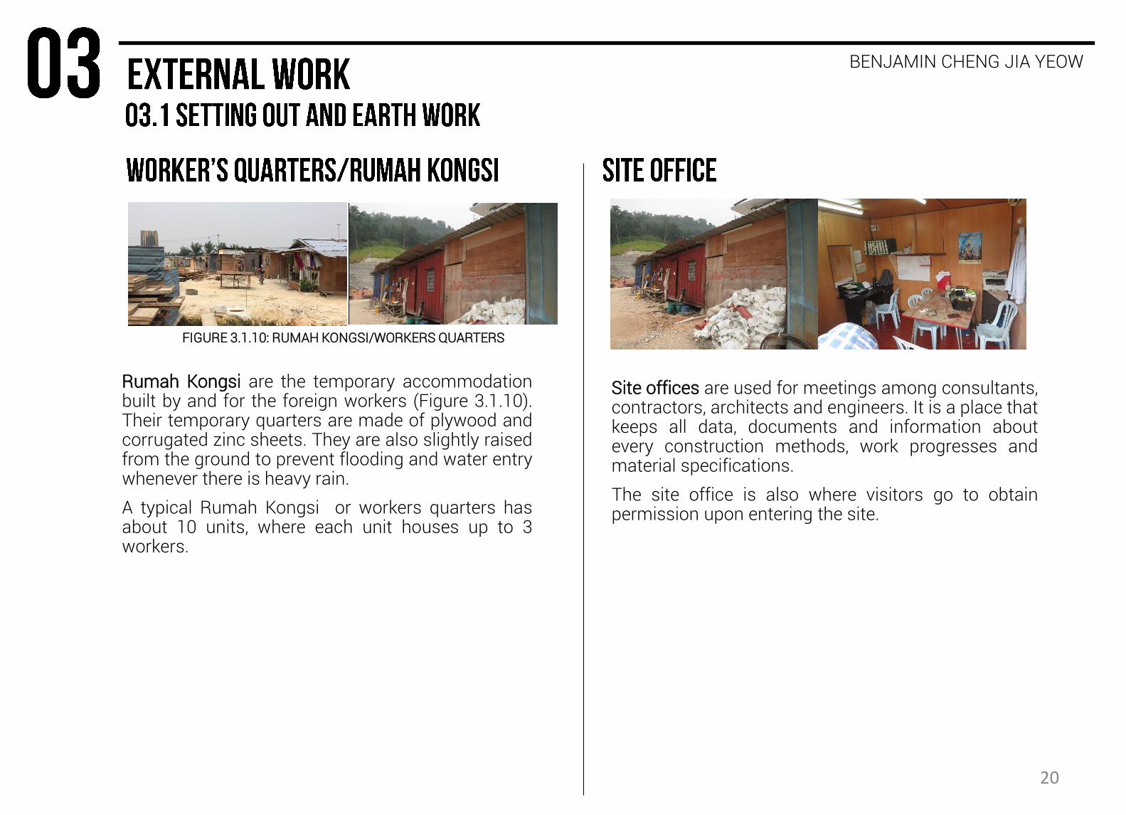
Rumah Kongsi are the temporary accommodation built by and for the foreign workers (Figure 3.1.10). Their temporary quarters are made of plywood and corrugated zinc sheets. They are also slightly raised from the ground to prevent flooding and water entry whenever there is heavy rain.
A typical Rumah Kongsi or workers quarters has about 10 units, where each unit houses up to 3 workers.
Site offices are used for meetings among consultants, contractors, architects and engineers. It is a place that keeps all data, documents and information about every construction methods, work progresses and material specifications.
The site office is also where visitors go to obtain permission upon entering the site.
FIGURE 3.1.10: RUMAH KONGSI/WORKERS QUARTERS
20
BENJAMIN CHENG JIA YEOW
NGE JIA CHEN
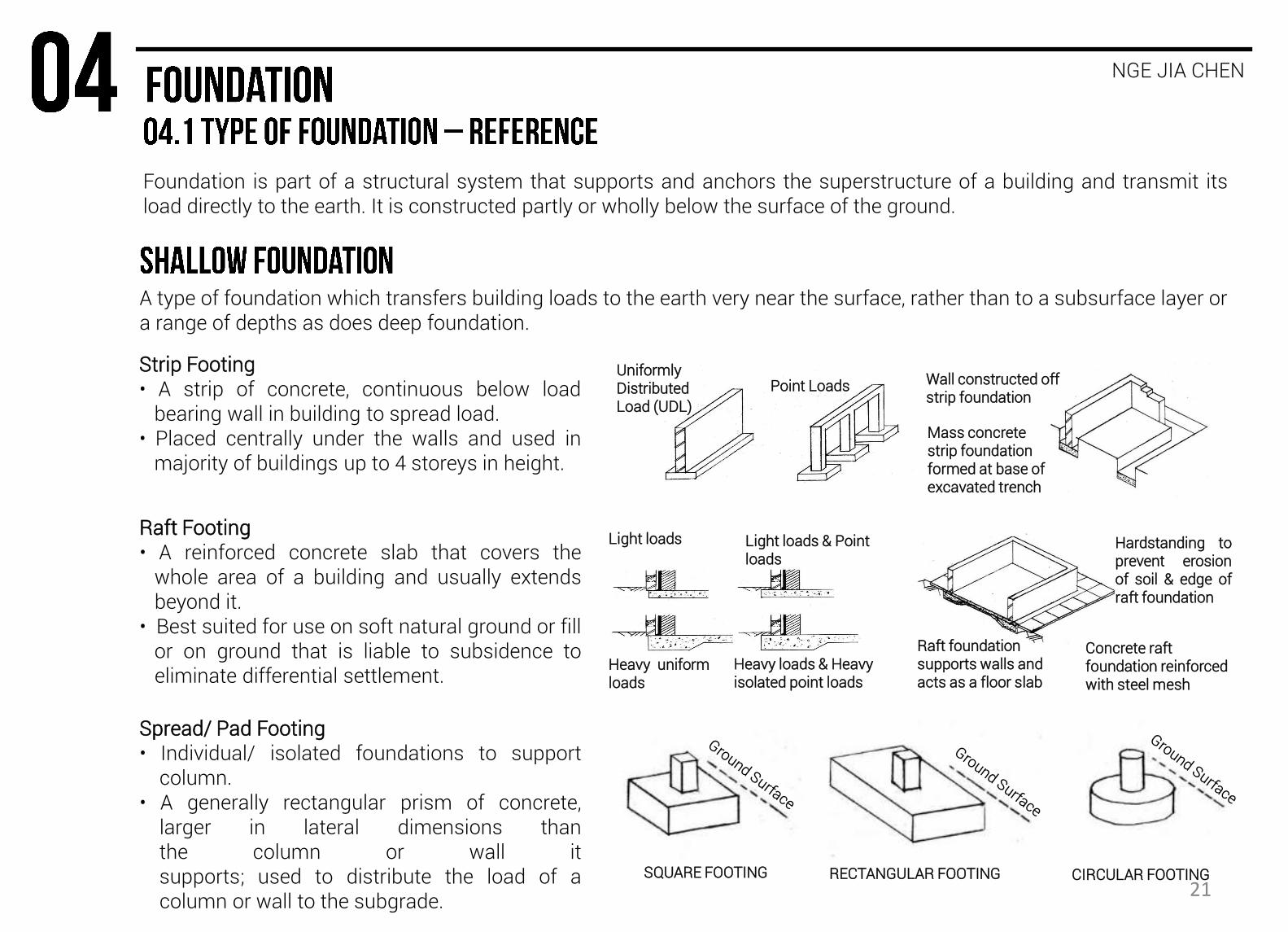
Foundation is part of a structural system that supports and anchors the superstructure of a building and transmit its load directly to the earth. It is constructed partly or wholly below the surface of the ground.
A type of foundation which transfers building loads to the earth very near the surface, rather than to a subsurface layer or a range of depths as does deep foundation.
Strip Footing • A strip of concrete, continuous below load bearing wall in building to spread load. • Placed centrally under the walls and used in majority of buildings up to 4 storeys in height.
Raft Footing • A reinforced concrete slab that covers the whole area of a building and usually extends beyond it. • Best suited for use on soft natural ground or fill or on ground that is liable to subsidence to eliminate differential settlement.
Spread/ Pad Footing • Individual/ isolated foundations to support column. • A generally rectangular prism of concrete, larger in lateral dimensions than the column or wall it supports; used to distribute the load of a column or wall to the subgrade.
Uniformly Distributed Load (UDL)
Mass concrete strip foundation formed at base of excavated trench
Wall constructed off strip foundation
Point Loads
Light loads
Heavy loads & Heavy isolated point loads
Light loads & Point loads
Heavy uniform loads
Raft foundation supports walls and acts as a floor slab
Concrete raft foundation reinforced with steel mesh
Hardstanding to prevent erosion of soil & edge of raft foundation
SQUARE FOOTING RECTANGULAR FOOTING CIRCULAR FOOTING 21

NGE JIA CHEN
A type of foundation which transfers building loads to the earth farther down from the surface than a shallow foundation does, to a subsurface layer or a range of depths.
Piled Foundation • ‘Columns’ extending into the ground. • Used in incompetent soil to transfer load to
competent load bearing soil or rock deeper within earth.
Pile Cap • Piles are generally driven closely together in group or
clusters that contain from two to twenty-five piles each.
• The load is distributed over the head of the piles in the group by means of a reinforced cast in-situ concrete pile cap.
PRECAST R.C PILE
STEEL H PILE
SHELL PILE
R.C PILE
BORED PILE
CAST IN-SITU
PILE
R.C. COLUMN
PILE CAP
FOUR PILES
FIVE SETS
THREE SETS
TWO SETS
FOUR SETS
22

NGE JIA CHEN
FIGURE 4.2.1 : FOUNDATION - SITE 1
FIGURE 4.2.2 : FOUNDATION - SITE 2
Column reinforcement starter bars or holding down bolts
8” x 8” R.C. Column
APPROVED FOUNDING MATERIAL
Footing Reinforcement, ½” dia. bars at 8” ctrs. each way use BRC A252 mesh for lightly loaded columns
PLAN
D= 12”
L= L
Finished Grade 4” to 6”
4” Slab
2’
6”
1’
8”
1’ 8”
1’
Remove landscape / top soil prior to excavation
COMPACTED FILL
• Columns of structural frame to a building • Individual pad foundation to support each column
23
NGE JIA CHEN
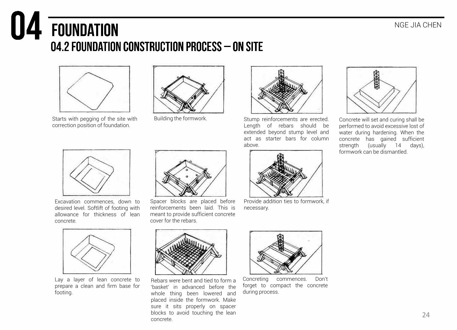
Starts with pegging of the site with correction position of foundation.
Excavation commences, down to desired level. Softlift of footing with allowance for thickness of lean concrete.
Lay a layer of lean concrete to prepare a clean and firm base for footing.
Building the formwork.
Spacer blocks are placed before reinforcements been laid. This is meant to provide sufficient concrete cover for the rebars.
Rebars were bent and tied to form a ‘basket’ in advanced before the whole thing been lowered and placed inside the formwork. Make sure it sits properly on spacer blocks to avoid touching the lean concrete.
Stump reinforcements are erected. Length of rebars should be extended beyond stump level and act as starter bars for column above.
Provide addition ties to formwork, if necessary.
Concreting commences. Don’t forget to compact the concrete during process.
Concrete will set and curing shall be performed to avoid excessive lost of water during hardening. When the concrete has gained sufficient strength (usually 14 days), formwork can be dismantled.
24
NGE JIA CHEN
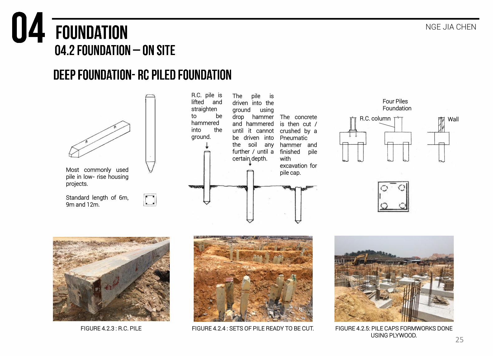
R.C. pile is lifted and straighten to be hammered into the ground.
The pile is driven into the ground using drop hammer and hammered until it cannot be driven into the soil any further / until a certain depth.
The concrete is then cut / crushed by a Pneumatic hammer and finished pile with excavation for pile cap. Most commonly used
pile in low- rise housing projects. Standard length of 6m, 9m and 12m.
Four Piles Foundation
Wall R.C. column
FIGURE 4.2.3 : R.C. PILE FIGURE 4.2.4 : SETS OF PILE READY TO BE CUT. FIGURE 4.2.5: PILE CAPS FORMWORKS DONE USING PLYWOOD.
25

LEE CZEN SHING
Beams are rigid structural members designed to carry and transfer transverse loads across space to supporting elements. The non concurrent pattern of forces subjects a beam to bend and deflect. Thus, it has to be resisted by the internal strength of the material
Timber Box Beam
Timber Joist
Universal Beam
Hollow Steel Tubing
Castellated Beam
Concrete is then poured into wooden formwork and It is then set to dry. 26

LEE CZEN SHING
• Rebar is incorporated into concrete • It provides extra tensile strength which in return creates tension • Comprises of either single rebar or double rebar • Divided into precast concrete and cast in-situ concrete
STEP 1: Rebar beam is assembled on site, which is also known as cast in-situ.
COLUMN
STARTER BAR
REBAR CAGE
FORM WORK
STEP 4: Finally, concrete is then poured into form work and left to dry
STEP 2: Rebar steel is then added as it good at reducing tension force
STEP 3: Form work is then added around the rebars.
COLUMN REINFORCEMENT
BEAM REINFORCEMENT
CONCRETE BEAM
REINFORCED CONCRETE COLUMN
COLUMN REINFORCEMENT
Beam to Column Connection
27

LEE CZEN SHING
KERN AREA BUCKLING
SHAFT
BASE
Form work (Wooden plank)
• It is a structure, usually temporary • Contains poured concrete to mould it to the required dimensions
and support it until it is able to support itself
Columns is a supporting pillar and a structural element which transfers the load of the structure and its live load through to the foundation and into the hard strata. Failure occurs when direct stress from axial load exceeds the compressive strength of the material available in the cross section. On the other hand, an eccentric load can produce bending and results in an uneven stress distribution in the section.
28

LEE CZEN SHING
STEP 4: Wooden planks are then placed as the form work
STEP 2: Layout work is then carried out
STEP 3: Starter bar is installed then followed by rebar cage
STARTER BAR
STUMP
REINFORCED BAR CAGE
FORMWORK
FORMWORK
STUMP
REBAR
STEP 1: Grid lines are drawn to dimensions (to determine where the columns would be placed).
PLACEMENT OF COLUMNS FIGURE 5.11: CONSTRUCTION PROCESS - SITE 1 FIGURE 5.1.2: CONSTRUCTION PROCESS - SITE 2
29
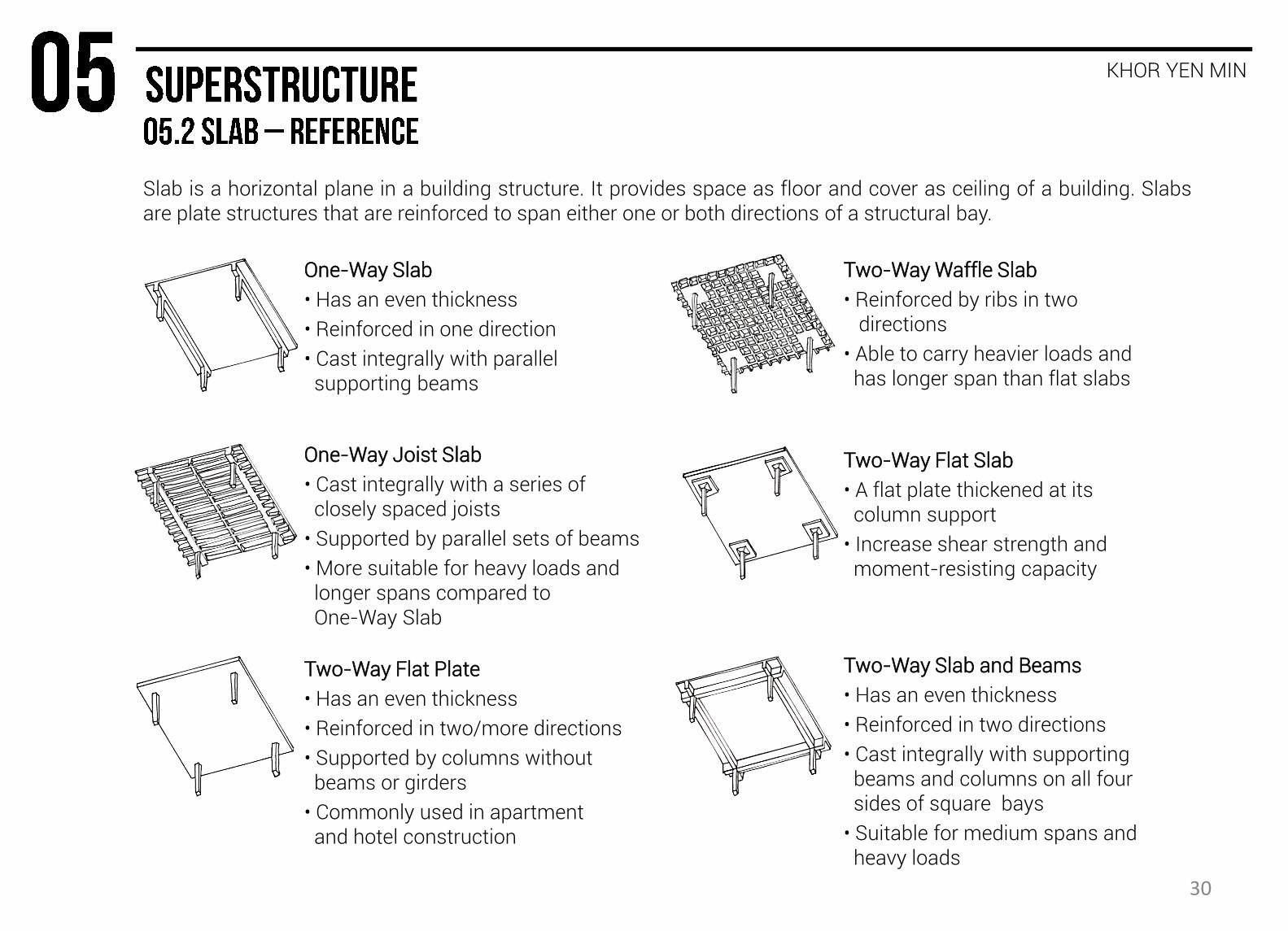
Slab is a horizontal plane in a building structure. It provides space as floor and cover as ceiling of a building. Slabs are plate structures that are reinforced to span either one or both directions of a structural bay.
KHOR YEN MIN
One-Way Slab
• Has an even thickness
• Reinforced in one direction
• Cast integrally with parallel supporting beams
One-Way Joist Slab
• Cast integrally with a series of closely spaced joists
• Supported by parallel sets of beams
• More suitable for heavy loads and longer spans compared to One-Way Slab
Two-Way Slab and Beams
• Has an even thickness
• Reinforced in two directions
• Cast integrally with supporting beams and columns on all four sides of square bays
• Suitable for medium spans and heavy loads
Two-Way Waffle Slab
• Reinforced by ribs in two directions
• Able to carry heavier loads and has longer span than flat slabs
Two-Way Flat Plate
• Has an even thickness
• Reinforced in two/more directions
• Supported by columns without beams or girders
• Commonly used in apartment and hotel construction
Two-Way Flat Slab
• A flat plate thickened at its column support
• Increase shear strength and moment-resisting capacity
30

KHOR YEN MIN
One-Way Slab (Site 1 and Site 2)
Two-Way Slab and Beam (Site 2)
FIGURE 5.2.3: PORCH - SITE 2 FIGURE 5.2.1: DINING AREA - SITE 1
FIGURE 5.2.2: LIVING AREA - SITE 2
• Ratio of longer side to shorter side is more than 2
• Main tension reinforcement bars in one single direction
• Load will be transferred to only two opposing beam or load bearing wall in both site buildings
• It is suitable for light and moderate load
• Load will be transferred to four support beams at all four sides of nearly square bays.
• It is effective for medium spans and it will support the load of master bedroom above it.
• Main tension reinforcement bars span both directions, parallel to the length and the width of the panel
• Ratio of longer side to shorter side is less than 2 or close to 1
31
KHOR YEN MIN
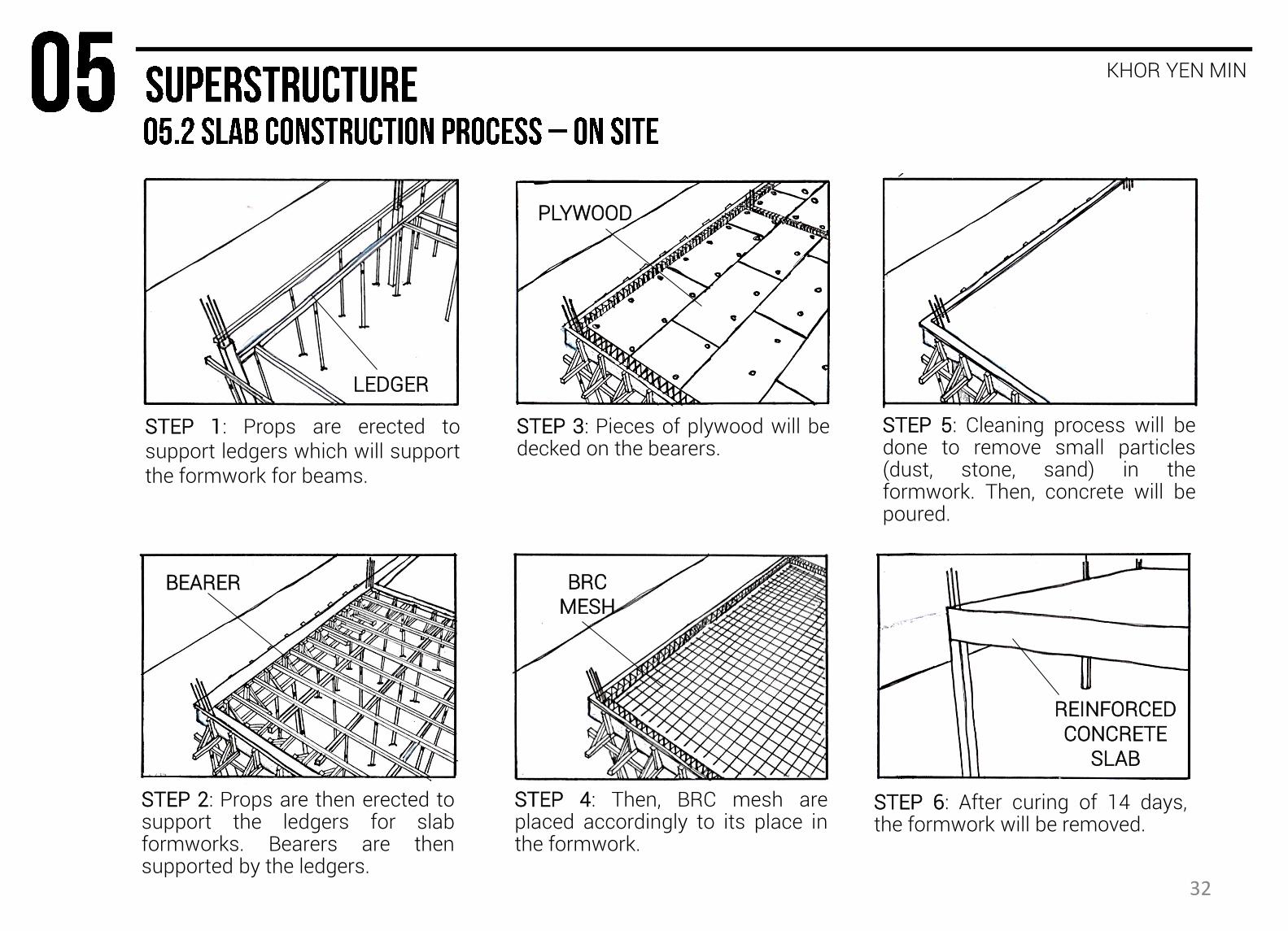
STEP 1: Props are erected to support ledgers which will support the formwork for beams.
STEP 2: Props are then erected to support the ledgers for slab formworks. Bearers are then supported by the ledgers.
STEP 3: Pieces of plywood will be decked on the bearers.
STEP 5: Cleaning process will be done to remove small particles (dust, stone, sand) in the formwork. Then, concrete will be poured.
STEP 6: After curing of 14 days, the formwork will be removed.
LEDGER
BRC MESH
REINFORCED CONCRETE
SLAB
BEARER
PLYWOOD
STEP 4: Then, BRC mesh are placed accordingly to its place in the formwork.
32
KHOR YEN MIN
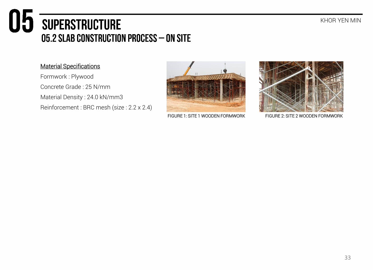
Material Specifications
Formwork : Plywood
Concrete Grade : 25 N/mm
Material Density : 24.0 kN/mm3
Reinforcement : BRC mesh (size : 2.2 x 2.4)
FIGURE 1: SITE 1 WOODEN FORMWORK FIGURE 2: SITE 2 WOODEN FORMWORK
33
A wall is a structure that defines an area, carries a load, or provides shelter or security. Walls are the vertical constructions of a building that enclose, separate, and protect its interior spaces. They may be load bearing structures of homogeneous or composite construction designed to support imposed loads from floors and roofs, or consist of a framework of columns and beams with non-structural panels attached to or filling in between them.
BRIDGET TAN SU TING
Some of the functions of wall include:
• To provide protection from weather;
• To separate interior spaces;
• To support upper floors and roofs together with their superimposed loads;
• To provide adequate thermal and sound insulation;
• For aesthetics and privacy
Wall Classification
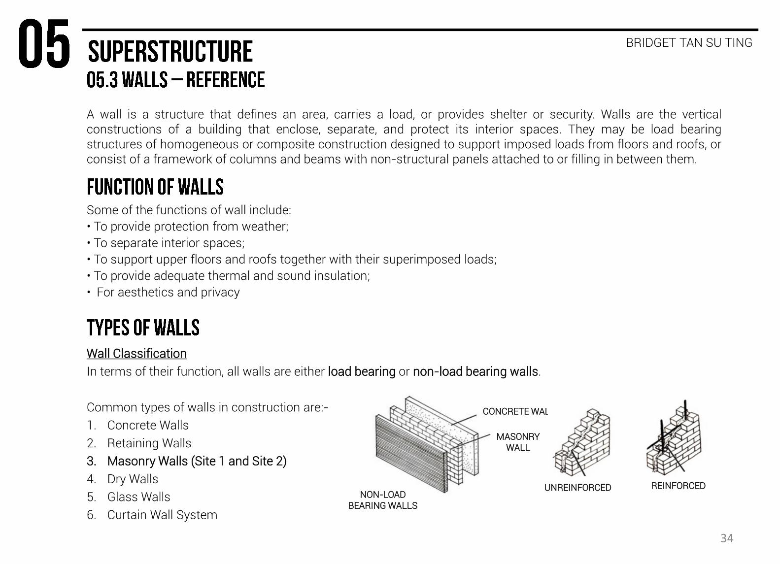
In terms of their function, all walls are either load bearing or non-load bearing walls.
Common types of walls in construction are:-
1. Concrete Walls
2. Retaining Walls
3. Masonry Walls (Site 1 and Site 2)
4. Dry Walls
5. Glass Walls
6. Curtain Wall System
CONCRETE WALL
MASONRY WALL
NON-LOAD BEARING WALLS
UNREINFORCED REINFORCED
34
BRIDGET TAN SU TING
• Masonry is the building of structures from individual units laid in and bound together by mortar; the term masonry can also refer to the units themselves.
Characteristics
• Load bearing or non- load bearing
• One of the most common materials for wall construction in Malaysia
• Durable
• Good sound insulation, fire insulation and thermal insulation
• Offers great flexibility in form and appearance
Common Types of Masonry
1. Bricks (heat-hardened clay units) • Clay bricks (Site A) • Cement bricks (Site A and Site B)
2. Concrete/cement blocks (chemically hardened units)
35
BRIDGET TAN SU TING
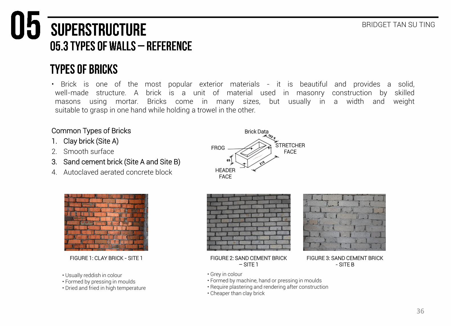
• Brick is one of the most popular exterior materials - it is beautiful and provides a solid, well-made structure. A brick is a unit of material used in masonry construction by skilled masons using mortar. Bricks come in many sizes, but usually in a width and weight suitable to grasp in one hand while holding a trowel in the other.
Common Types of Bricks
1. Clay brick (Site A)
2. Smooth surface
3. Sand cement brick (Site A and Site B)
4. Autoclaved aerated concrete block
FIGURE 1: CLAY BRICK - SITE 1 FIGURE 2: SAND CEMENT BRICK – SITE 1
FIGURE 3: SAND CEMENT BRICK - SITE B
Brick Data
HEADER FACE
FROG STRETCHER FACE
• Usually reddish in colour • Formed by pressing in moulds • Dried and fried in high temperature
• Grey in colour • Formed by machine, hand or pressing in moulds • Require plastering and rendering after construction • Cheaper than clay brick
36
BRIDGET TAN SU TING
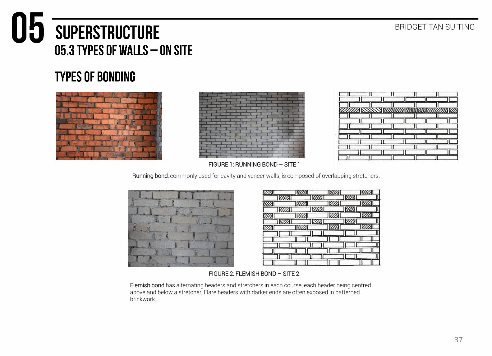
FIGURE 1: RUNNING BOND – SITE 1
FIGURE 2: FLEMISH BOND – SITE 2
Running bond, commonly used for cavity and veneer walls, is composed of overlapping stretchers.
Flemish bond has alternating headers and stretchers in each course, each header being centred above and below a stretcher. Flare headers with darker ends are often exposed in patterned brickwork.
37
BRIDGET TAN SU TING
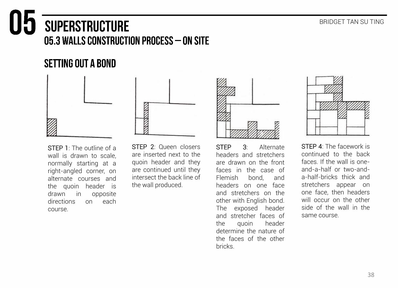
STEP 1: The outline of a wall is drawn to scale, normally starting at a right-angled corner, on alternate courses and the quoin header is drawn in opposite directions on each course.
STEP 2: Queen closers are inserted next to the quoin header and they are continued until they intersect the back line of the wall produced.
STEP 3: Alternate headers and stretchers are drawn on the front faces in the case of Flemish bond, and headers on one face and stretchers on the other with English bond. The exposed header and stretcher faces of the quoin header determine the nature of the faces of the other bricks.
STEP 4: The facework is continued to the back faces. If the wall is one-and-a-half or two-and-a-half-bricks thick and stretchers appear on one face, then headers will occur on the other side of the wall in the same course.
38
BRIDGET TAN SU TING
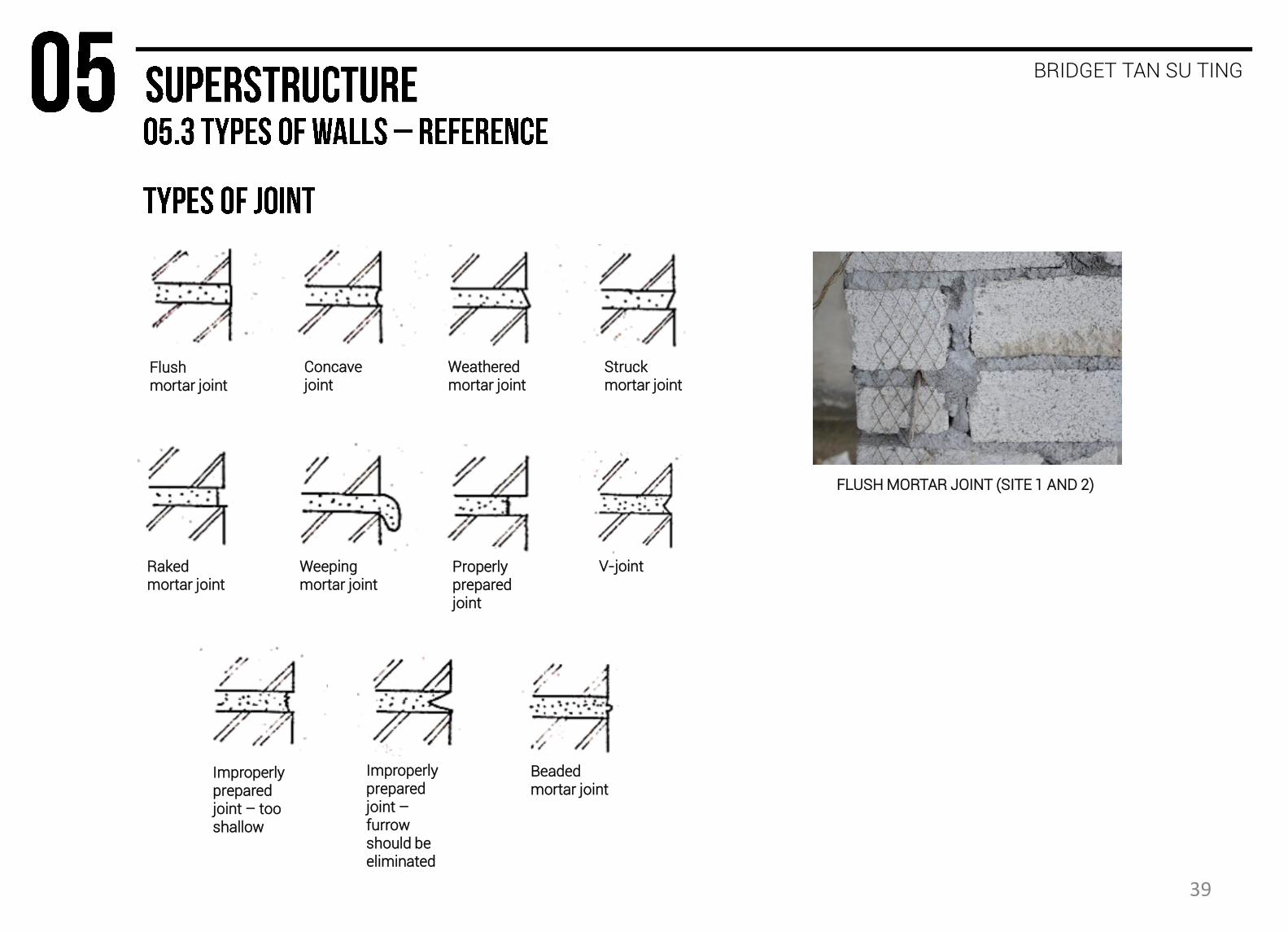
Flush mortar joint
Concave joint
Weathered mortar joint
Struck mortar joint
Raked mortar joint
Weeping mortar joint
Properly prepared joint
V-joint
Improperly prepared joint – too shallow
Improperly prepared joint – furrow should be eliminated
Beaded mortar joint
FLUSH MORTAR JOINT (SITE 1 AND 2)
39
BRIDGET TAN SU TING
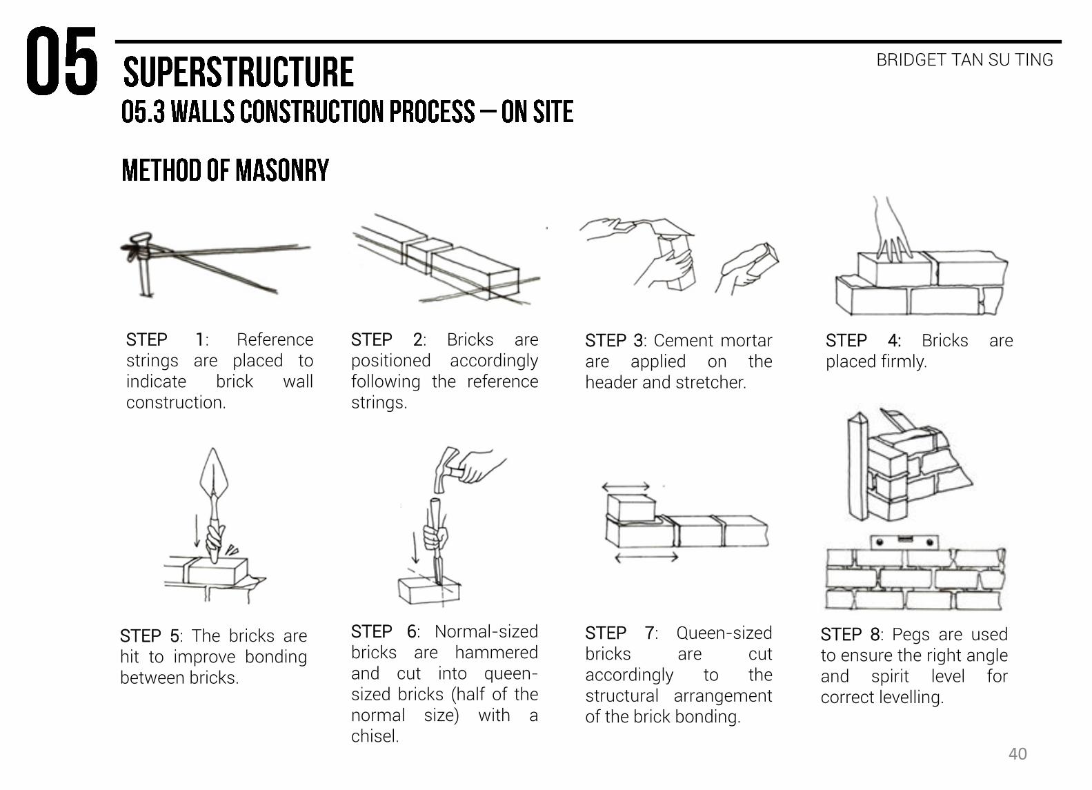
STEP 1: Reference strings are placed to indicate brick wall construction.
STEP 2: Bricks are positioned accordingly following the reference strings.
STEP 3: Cement mortar are applied on the header and stretcher.
STEP 4: Bricks are placed firmly.
STEP 5: The bricks are hit to improve bonding between bricks.
STEP 6: Normal-sized bricks are hammered and cut into queen-sized bricks (half of the normal size) with a chisel.
STEP 7: Queen-sized bricks are cut accordingly to the structural arrangement of the brick bonding.
STEP 8: Pegs are used to ensure the right angle and spirit level for correct levelling.
40
BRIDGET TAN SU TING
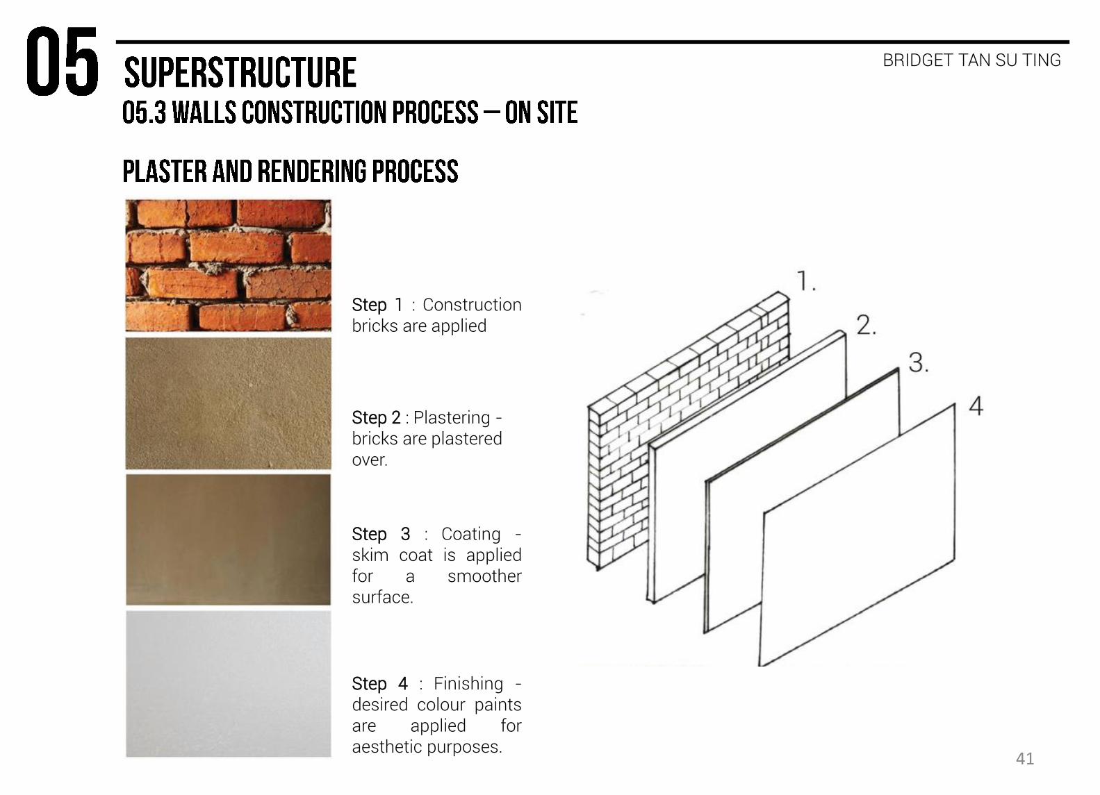
Step 4 : Finishing - desired colour paints are applied for aesthetic purposes.
Step 1 : Construction bricks are applied
Step 2 : Plastering - bricks are plastered over.
Step 3 : Coating - skim coat is applied for a smoother surface.
41

BRIDGET TAN SU TING
ANGLE BEAD
Metal angle beads are used for precise wall angles.
REFERENCE STRING
Strings are nailed on the brick walls for even plastering work.
CEMENT PIT Pits are used to mark
the thickness of plastering for even layering.
PLASTER PLASTIC MESH
Plaster plastic mesh are used to avoid dry cracks on the brick surfaces.
EXPANDED STEEL WIRE MESH
Expanded steel wire mesh are placed in between the bricks to strengthen the hold of the brick wall construction.
Few final courses of bricks are slanted to fill in the gap between the bricks and slab for a better hold of the ground beam that will be placed.
42
AIDA JUNITA BINTI ZULKIFLEE
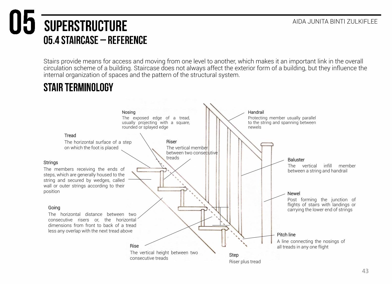
Tread
The horizontal surface of a step on which the foot is placed
Nosing
The exposed edge of a tread, usually projecting with a square, rounded or splayed edge
Riser
The vertical member between two consecutive treads
Step
Riser plus tread
Going
The horizontal distance between two consecutive risers or, the horizontal dimensions from front to back of a tread less any overlap with the next tread above
Rise
The vertical height between two consecutive treads
Newel
Post forming the junction of flights of stairs with landings or carrying the lower end of strings
Strings
The members receiving the ends of steps, which are generally housed to the string and secured by wedges, called wall or outer strings according to their position
Handrail
Protecting member usually parallel to the string and spanning between newels
Baluster
The vertical infill member between a string and handrail
Pitch line
A line connecting the nosings of all treads in any one flight
Stairs provide means for access and moving from one level to another, which makes it an important link in the overall circulation scheme of a building. Staircase does not always affect the exterior form of a building, but they influence the internal organization of spaces and the pattern of the structural system.
43
AIDA JUNITA BINTI ZULKIFLEE
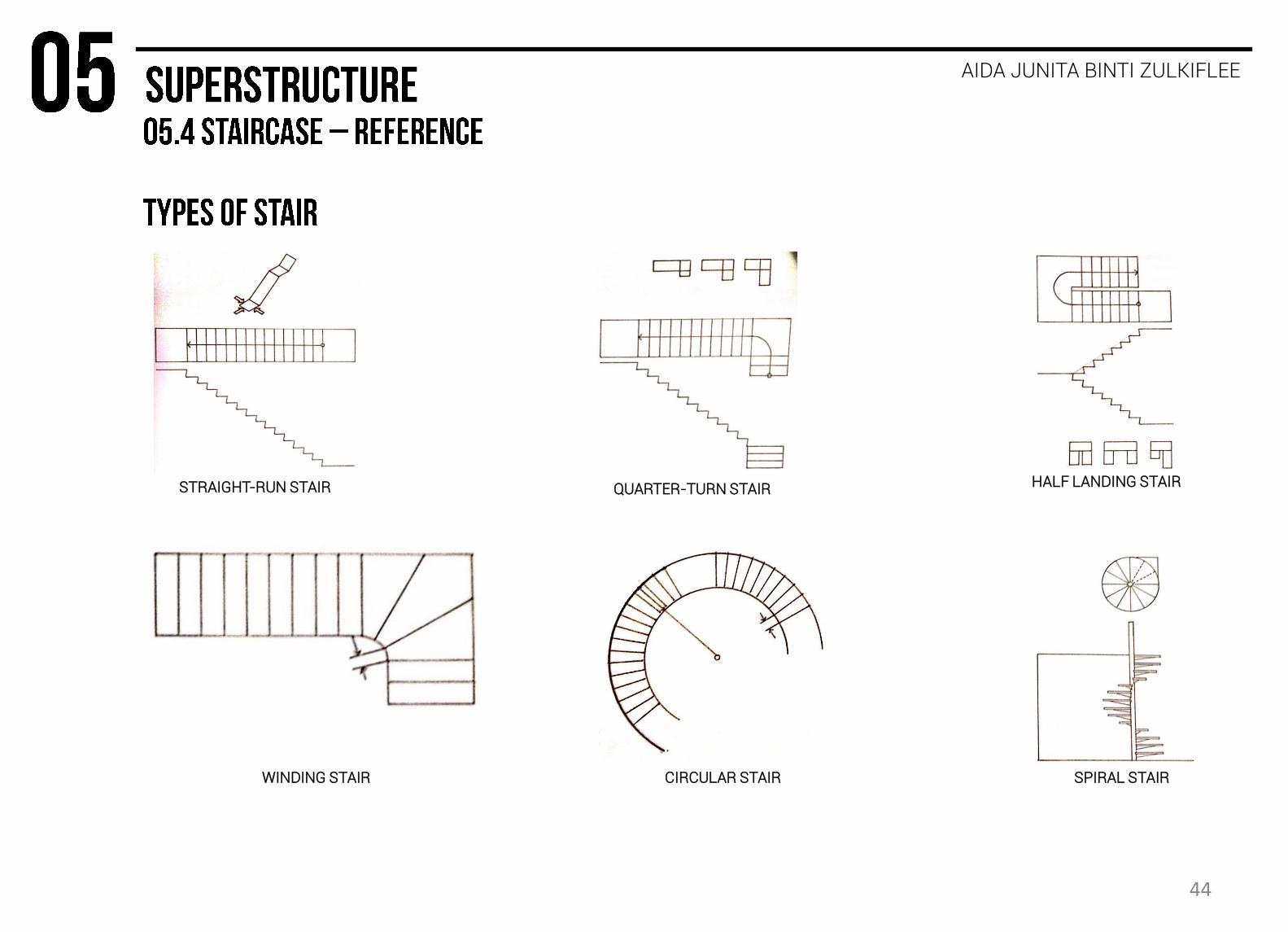
STRAIGHT-RUN STAIR QUARTER-TURN STAIR HALF LANDING STAIR
WINDING STAIR CIRCULAR STAIR SPIRAL STAIR
44
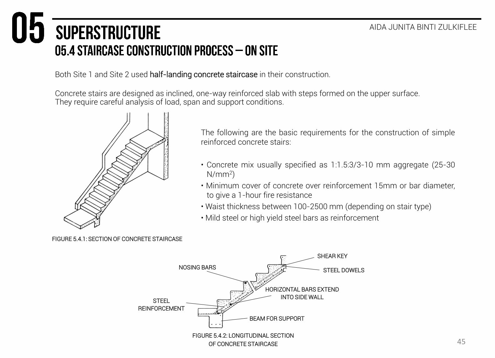
Both Site 1 and Site 2 used half-landing concrete staircase in their construction.
Concrete stairs are designed as inclined, one-way reinforced slab with steps formed on the upper surface. They require careful analysis of load, span and support conditions.
AIDA JUNITA BINTI ZULKIFLEE
The following are the basic requirements for the construction of simple reinforced concrete stairs:
• Concrete mix usually specified as 1:1.5:3/3-10 mm aggregate (25-30 N/mm2)
• Minimum cover of concrete over reinforcement 15mm or bar diameter, to give a 1-hour fire resistance
• Waist thickness between 100-2500 mm (depending on stair type)
• Mild steel or high yield steel bars as reinforcement
FIGURE 5.4.1: SECTION OF CONCRETE STAIRCASE
FIGURE 5.4.2: LONGITUDINAL SECTION
OF CONCRETE STAIRCASE
SHEAR KEY
STEEL DOWELS
HORIZONTAL BARS EXTEND
INTO SIDE WALL STEEL
REINFORCEMENT
BEAM FOR SUPPORT
NOSING BARS
45
AIDA JUNITA BINTI ZULKIFLEE
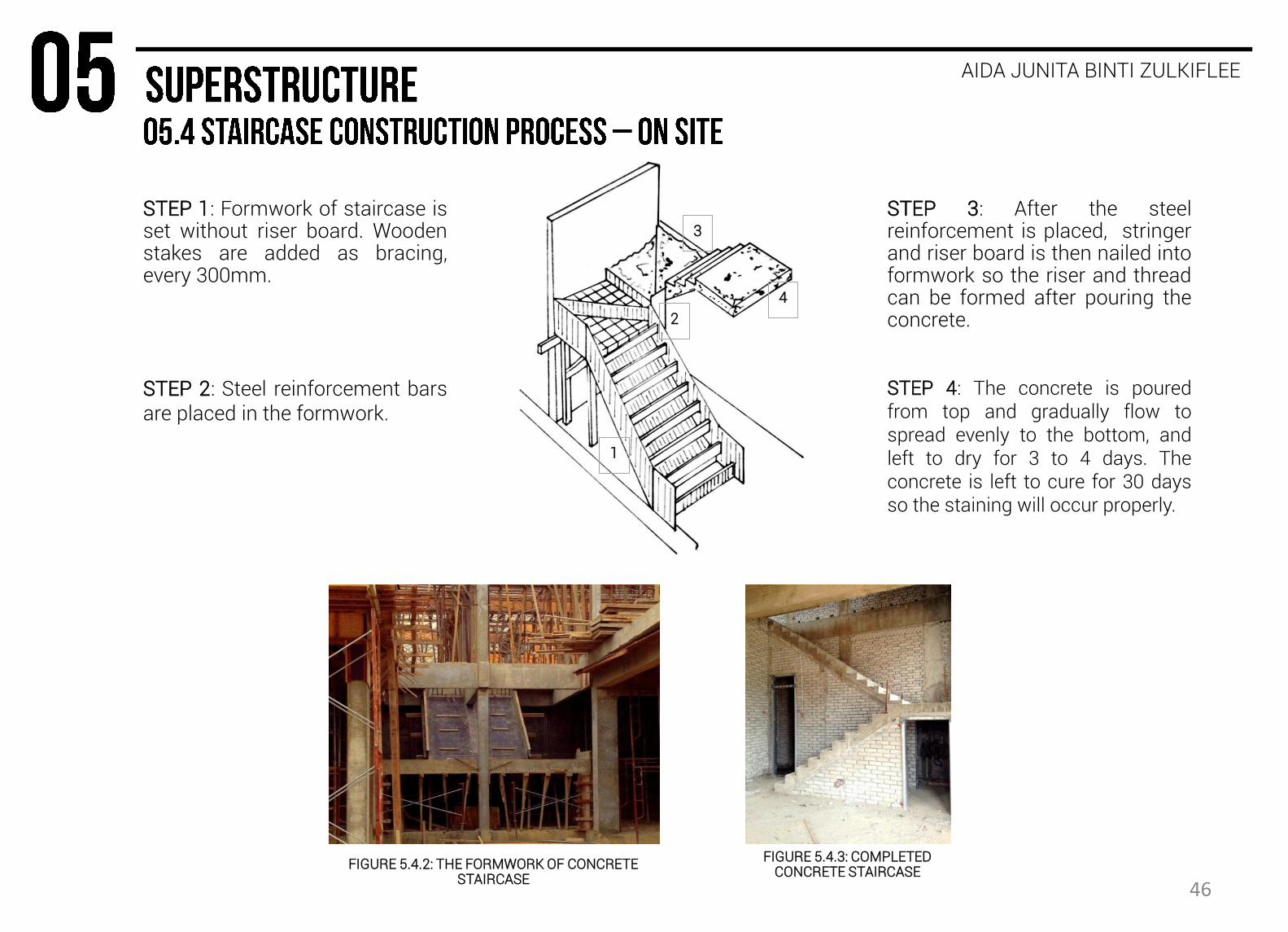
FIGURE 5.4.2: THE FORMWORK OF CONCRETE STAIRCASE
FIGURE 5.4.3: COMPLETED CONCRETE STAIRCASE
STEP 1: Formwork of staircase is set without riser board. Wooden stakes are added as bracing, every 300mm.
STEP 2: Steel reinforcement bars are placed in the formwork.
STEP 4: The concrete is poured from top and gradually flow to spread evenly to the bottom, and left to dry for 3 to 4 days. The concrete is left to cure for 30 days so the staining will occur properly.
STEP 3: After the steel reinforcement is placed, stringer and riser board is then nailed into formwork so the riser and thread can be formed after pouring the concrete.
1
2
3
4
46
AIDA JUNITA BINTI ZULKIFLEE
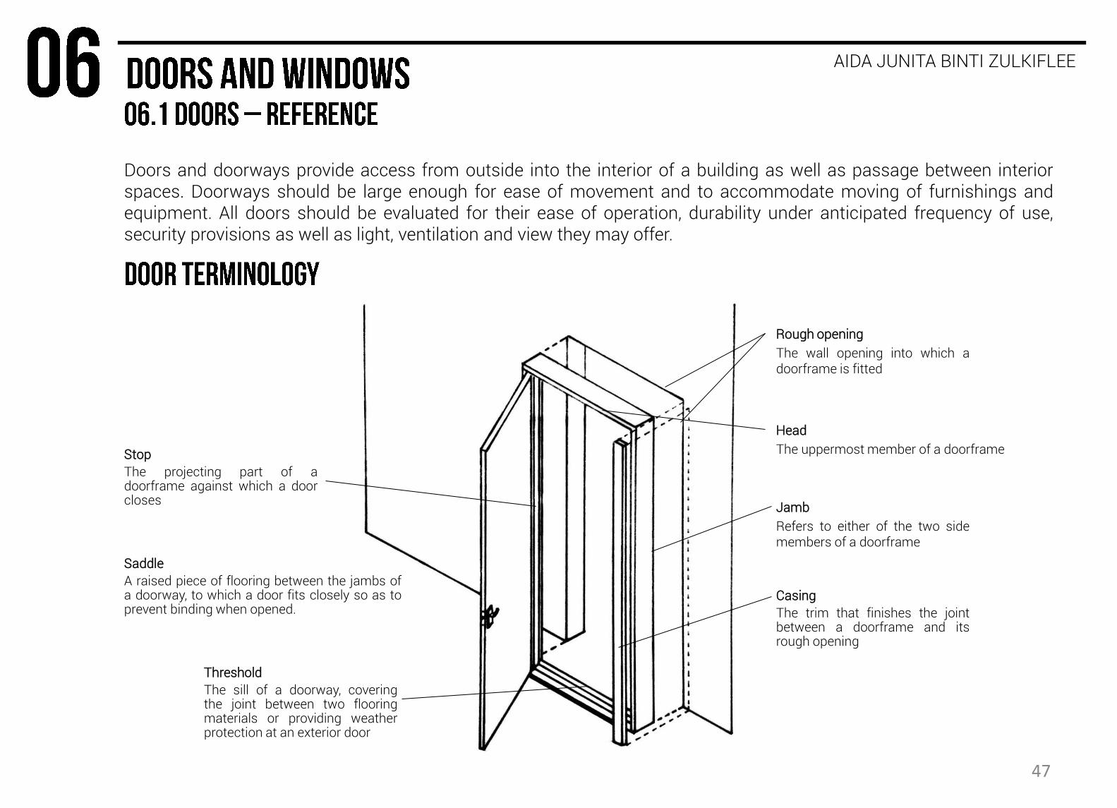
Rough opening
The wall opening into which a doorframe is fitted
Head
The uppermost member of a doorframe
Jamb
Refers to either of the two side members of a doorframe
Stop
The projecting part of a doorframe against which a door closes
Casing
The trim that finishes the joint between a doorframe and its rough opening
Threshold
The sill of a doorway, covering the joint between two flooring materials or providing weather protection at an exterior door
Saddle
A raised piece of flooring between the jambs of a doorway, to which a door fits closely so as to prevent binding when opened.
Doors and doorways provide access from outside into the interior of a building as well as passage between interior spaces. Doorways should be large enough for ease of movement and to accommodate moving of furnishings and equipment. All doors should be evaluated for their ease of operation, durability under anticipated frequency of use, security provisions as well as light, ventilation and view they may offer.
47
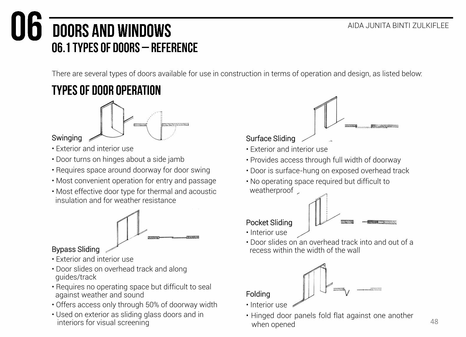
There are several types of doors available for use in construction in terms of operation and design, as listed below:
AIDA JUNITA BINTI ZULKIFLEE
Swinging
• Exterior and interior use
• Door turns on hinges about a side jamb
• Requires space around doorway for door swing
• Most convenient operation for entry and passage
• Most effective door type for thermal and acoustic insulation and for weather resistance
Bypass Sliding
• Exterior and interior use
• Door slides on overhead track and along guides/track
• Requires no operating space but difficult to seal against weather and sound
• Offers access only through 50% of doorway width
• Used on exterior as sliding glass doors and in interiors for visual screening
Surface Sliding
• Exterior and interior use
• Provides access through full width of doorway
• Door is surface-hung on exposed overhead track
• No operating space required but difficult to weatherproof
Pocket Sliding
• Interior use
• Door slides on an overhead track into and out of a recess within the width of the wall
Folding
• Interior use
• Hinged door panels fold flat against one another when opened 48

There are several types of doors available for use in construction in terms of operation and design, as listed below:
AIDA JUNITA BINTI ZULKIFLEE
FLUSH GLASS VISION NARROW LIGHT FULL-LOUVERED VISION/LOUVERED
A door frame is attached to the opening in which a door is to be fitted. It provides a surround for the door and is the member to which a door is fixed or hung. Frames should be securely fixed to the wall in which they sit, using frame fixings for masonry and screws for timber.
MASONRY WALLS WOOD STUD WALLS STEEL STUD WALLS
49
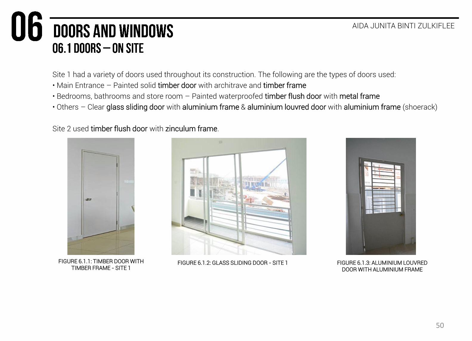
Site 1 had a variety of doors used throughout its construction. The following are the types of doors used:
• Main Entrance – Painted solid timber door with architrave and timber frame
• Bedrooms, bathrooms and store room – Painted waterproofed timber flush door with metal frame
• Others – Clear glass sliding door with aluminium frame & aluminium louvred door with aluminium frame (shoerack)
Site 2 used timber flush door with zinculum frame.
AIDA JUNITA BINTI ZULKIFLEE
FIGURE 6.1.1: TIMBER DOOR WITH TIMBER FRAME - SITE 1
FIGURE 6.1.2: GLASS SLIDING DOOR - SITE 1 FIGURE 6.1.3: ALUMINIUM LOUVRED DOOR WITH ALUMINIUM FRAME
50

AIDA JUNITA BINTI ZULKIFLEE
STANDARD DOUBLE-RABBET FRAME
Both Site 1 and Site 2 used metal door frame.
Site 1 used double repeated aluminium door frame where as Site 2 used single repeated zinculum frame.
SINGLE RABBET FRAME
FIGURE 6.1.4: ALUMINIUM DOOR FRAME - SITE 1 FIGURE 6.1.5: ZINCULUM DOOR FRAME - SITE 2
51

AIDA JUNITA BINTI ZULKIFLEE
STEP 1: Location of the doors is measured and marked. A few layers of bricks are then placed beside the markings.
STEP 2: The door frame is slotted into the marked position. The jamb of the door is nailed into the masonry wall for support. Bricks are then continued to be laid.
STEP 3: Pre-cast concrete lintel is bind with mortar and placed on top of the door head. Lintel is constructed so that no excessive vertical force is exerted on the door frame.
STEP 4: For timber door frame, wall is plastered and main frame is installed. For aluminium door frame, mortar is filled in the space between the gap and masonry wall before the wall is plastered.
STEP 5: Shims are placed on the hinges’ side to form a continuous gap in between. The hinge is then nailed into the side door jamb.
STEP 6: Casing (architrave) is installed to ensure cracks and flaws in the joining is hidden.
52

Windows are openings in the wall or roof of a building that is fitted with glass or other transparent material in a frame to admit light or air and allow people to see out.
KHOR YEN MIN
JAMB
FRAME
HINGE
GLASS UNIT
WINDOW BAR
BOLT
RESPONSE PLATE
HANDLE
Fixed • Ventilation : 0% • Consists of a frame and stationary sash
Casement • Ventilation : 100% • Consists of operating sashes that are side-hinged and usually swing outwards.
Awning & Hopper • Ventilation : 100% • Consists of operating sashes that swing outward on hinges attached to the top of their frame.
Sliding • Ventilation : 50% • Consists two or more sashes which at least one slides along horizontal grooves or tracks
Double-Hung • Ventilation : 50% • Consists of two vertically sliding sashes which each in separate grooves or tracks.
Jolousie • Ventilation : 100% • Consists of horizontal glass or wood louvers that is slanted in a fixed angle in a common frame.
Pivoting • Ventilation : 100% • Consists of sashes that rotate 90° or 180° about a vertical or horizontal axis at or near their centers.
Window Terminology
53
KHOR YEN MIN
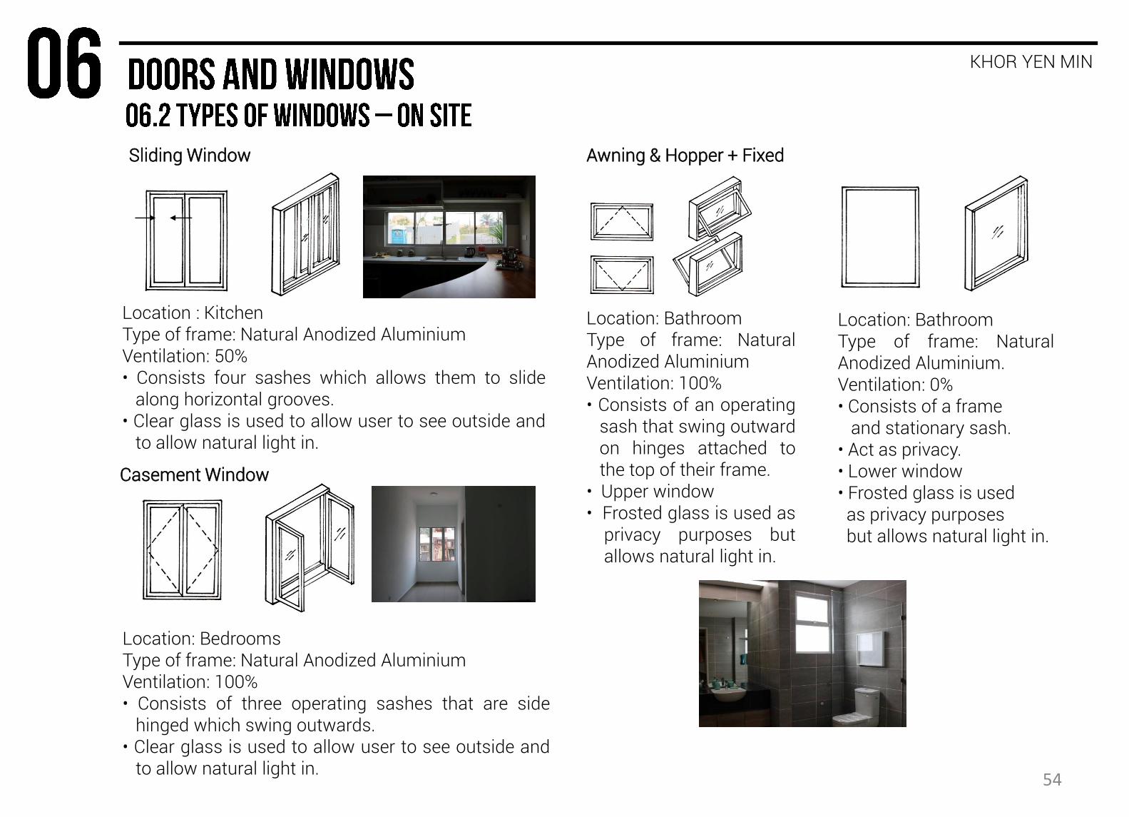
Casement Window
Location : Kitchen Type of frame: Natural Anodized Aluminium Ventilation: 50% • Consists four sashes which allows them to slide along horizontal grooves. • Clear glass is used to allow user to see outside and to allow natural light in.
Location: Bedrooms Type of frame: Natural Anodized Aluminium Ventilation: 100% • Consists of three operating sashes that are side hinged which swing outwards. • Clear glass is used to allow user to see outside and to allow natural light in.
54
Sliding Window Awning & Hopper + Fixed
Location: Bathroom Type of frame: Natural Anodized Aluminium Ventilation: 100% • Consists of an operating sash that swing outward on hinges attached to the top of their frame. • Upper window • Frosted glass is used as privacy purposes but allows natural light in.
Location: Bathroom Type of frame: Natural Anodized Aluminium. Ventilation: 0% • Consists of a frame and stationary sash. • Act as privacy. • Lower window • Frosted glass is used as privacy purposes but allows natural light in.
KHOR YEN MIN
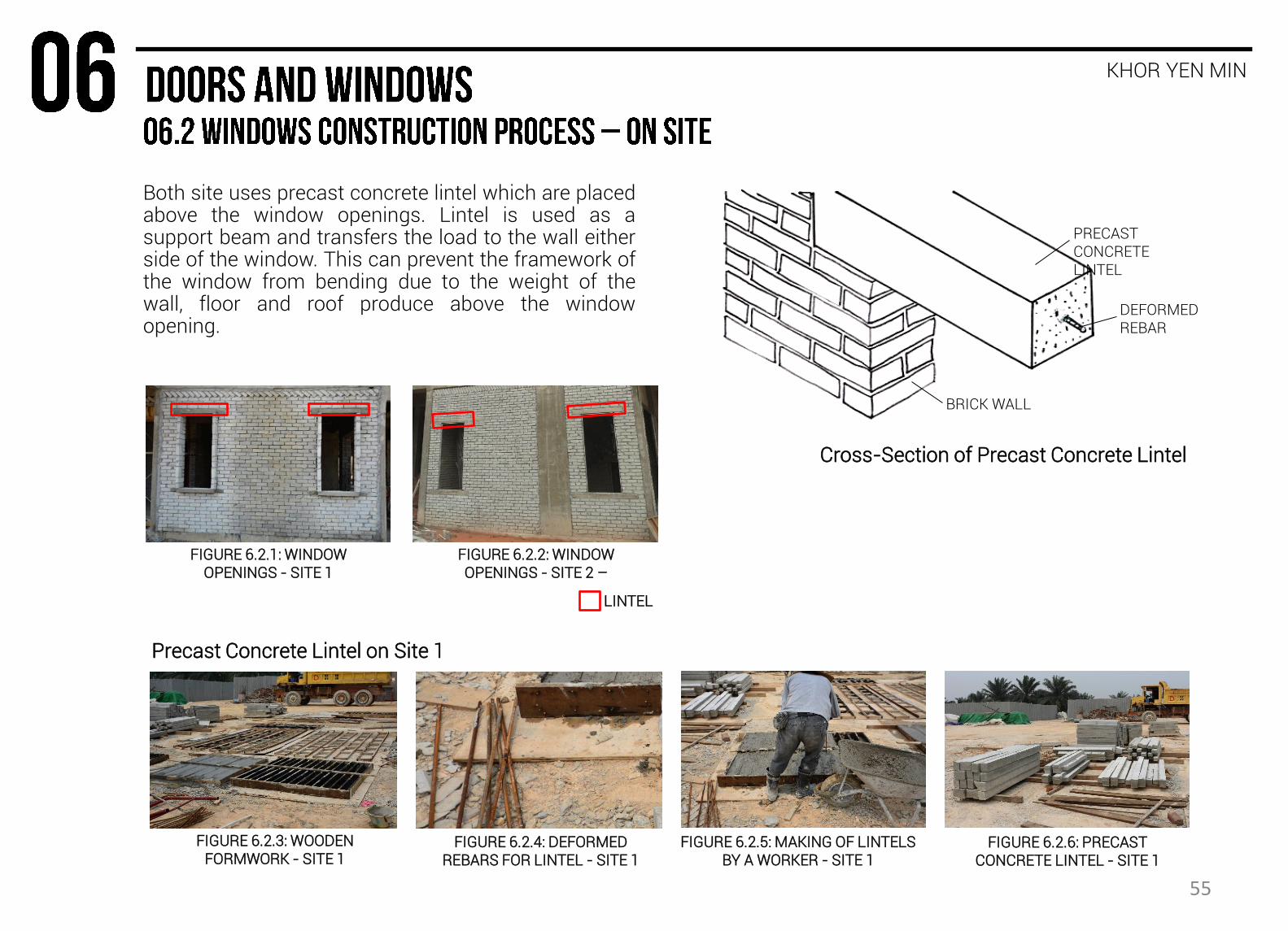
Both site uses precast concrete lintel which are placed above the window openings. Lintel is used as a support beam and transfers the load to the wall either side of the window. This can prevent the framework of the window from bending due to the weight of the wall, floor and roof produce above the window opening.
FIGURE 6.2.3: WOODEN FORMWORK - SITE 1
FIGURE 6.2.4: DEFORMED REBARS FOR LINTEL - SITE 1
FIGURE 6.2.6: PRECAST CONCRETE LINTEL - SITE 1
FIGURE 6.2.1: WINDOW OPENINGS - SITE 1
FIGURE 6.2.2: WINDOW OPENINGS - SITE 2 –
DEFORMED REBAR
PRECAST CONCRETE LINTEL
BRICK WALL
Cross-Section of Precast Concrete Lintel
Precast Concrete Lintel on Site 1
FIGURE 6.2.5: MAKING OF LINTELS BY A WORKER - SITE 1
LINTEL
55
KHOR YEN MIN
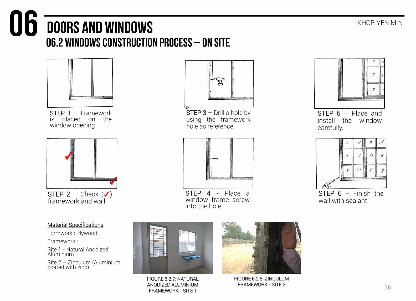
STEP 1 – Framework is placed on the window opening
STEP 2 – Check (✓) framework and wall
STEP 3 – Drill a hole by using the framework hole as reference.
STEP 4 - Place a window frame screw into the hole.
STEP 5 – Place and install the window carefully.
STEP 6 – Finish the wall with sealant
FIGURE 6.2.7: NATURAL ANODIZED ALUMINIUM FRAMEWORK - SITE 1
FIGURE 6.2.8: ZINCULUM FRAMEWORK - SITE 2
Material Specifications
Formwork : Plywood
Framework :
Site 1 - Natural Anodized Aluminium
Site 2 – Zinculum (Aluminium coated with zinc)
✓
✓
56
WONG ZHEN FAI
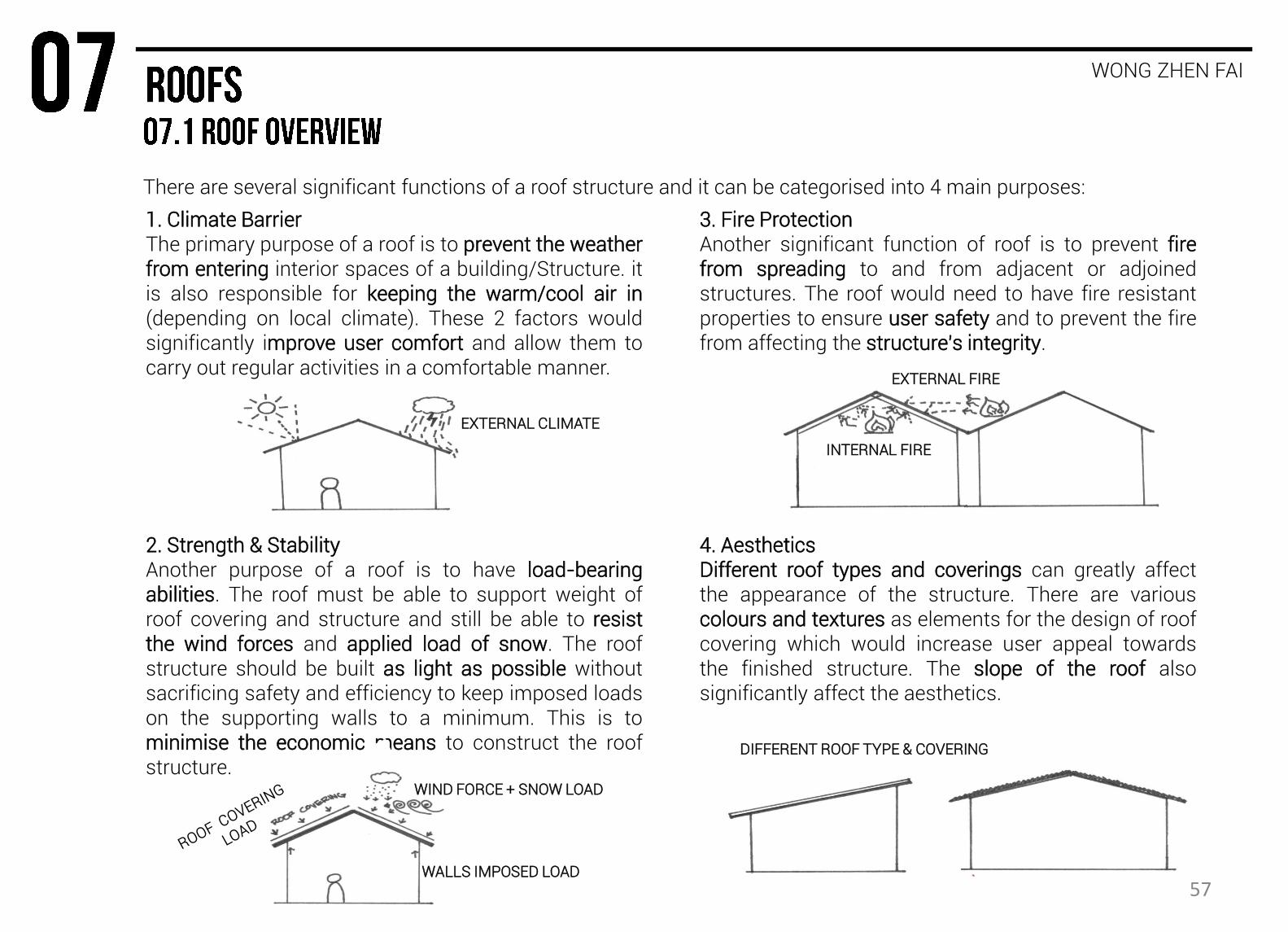
There are several significant functions of a roof structure and it can be categorised into 4 main purposes:
2. Strength & Stability Another purpose of a roof is to have load-bearing abilities. The roof must be able to support weight of roof covering and structure and still be able to resist the wind forces and applied load of snow. The roof structure should be built as light as possible without sacrificing safety and efficiency to keep imposed loads on the supporting walls to a minimum. This is to minimise the economic means to construct the roof structure.
3. Fire Protection Another significant function of roof is to prevent fire from spreading to and from adjacent or adjoined structures. The roof would need to have fire resistant properties to ensure user safety and to prevent the fire from affecting the structure’s integrity.
4. Aesthetics Different roof types and coverings can greatly affect the appearance of the structure. There are various colours and textures as elements for the design of roof covering which would increase user appeal towards the finished structure. The slope of the roof also significantly affect the aesthetics.
1. Climate Barrier The primary purpose of a roof is to prevent the weather from entering interior spaces of a building/Structure. it is also responsible for keeping the warm/cool air in (depending on local climate). These 2 factors would significantly improve user comfort and allow them to carry out regular activities in a comfortable manner.
EXTERNAL CLIMATE
WIND FORCE + SNOW LOAD
WALLS IMPOSED LOAD
INTERNAL FIRE
EXTERNAL FIRE
DIFFERENT ROOF TYPE & COVERING
57
WONG ZHEN FAI
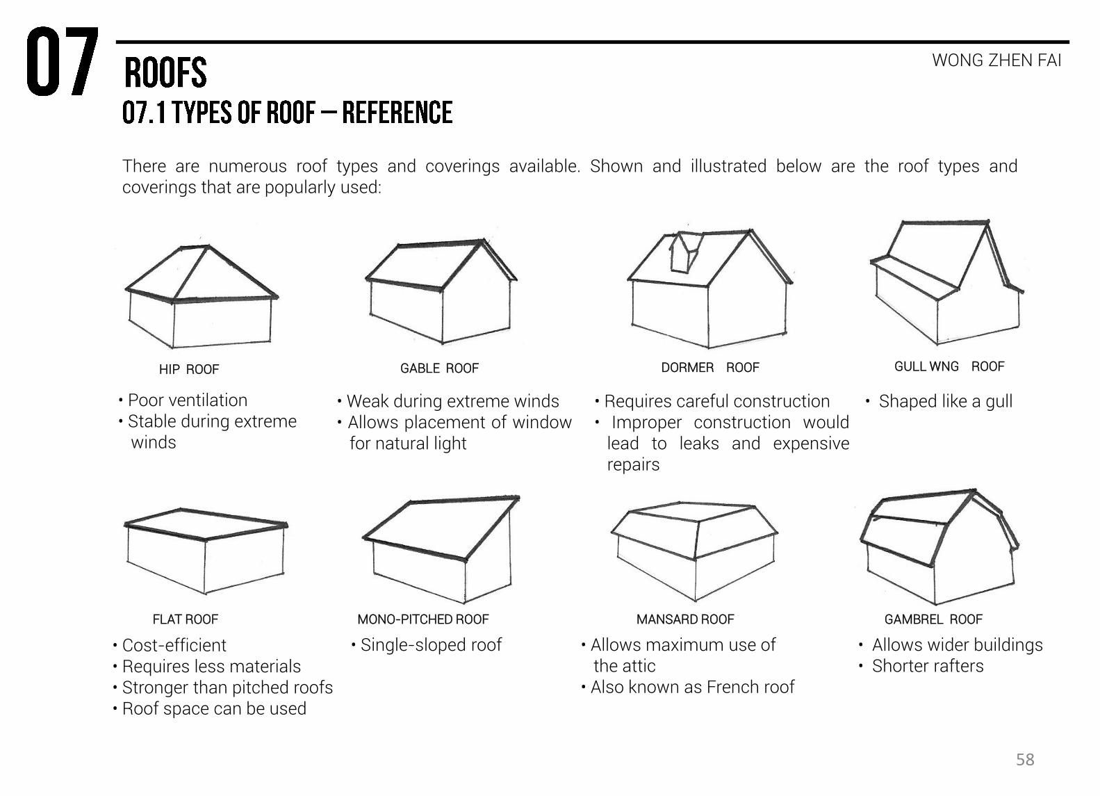
There are numerous roof types and coverings available. Shown and illustrated below are the roof types and coverings that are popularly used:
HIP ROOF GABLE ROOF GULL WNG ROOF
GAMBREL ROOF FLAT ROOF MONO-PITCHED ROOF
• Poor ventilation • Stable during extreme winds
• Weak during extreme winds • Allows placement of window for natural light
• Requires careful construction • Improper construction would lead to leaks and expensive repairs
• Shaped like a gull
• Cost-efficient • Requires less materials • Stronger than pitched roofs • Roof space can be used
• Single-sloped roof • Allows maximum use of the attic • Also known as French roof
• Allows wider buildings • Shorter rafters
DORMER ROOF
MANSARD ROOF
58
WONG ZHEN FAI
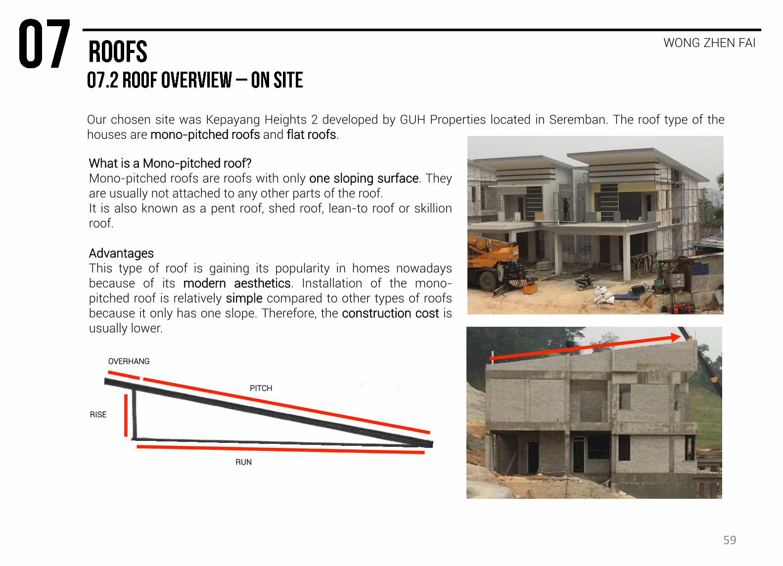
Our chosen site was Kepayang Heights 2 developed by GUH Properties located in Seremban. The roof type of the houses are mono-pitched roofs and flat roofs.
What is a Mono-pitched roof? Mono-pitched roofs are roofs with only one sloping surface. They are usually not attached to any other parts of the roof. It is also known as a pent roof, shed roof, lean-to roof or skillion roof. Advantages This type of roof is gaining its popularity in homes nowadays because of its modern aesthetics. Installation of the mono-pitched roof is relatively simple compared to other types of roofs because it only has one slope. Therefore, the construction cost is usually lower.
RUN
RISE
PITCH
OVERHANG
59
WONG ZHEN FAI
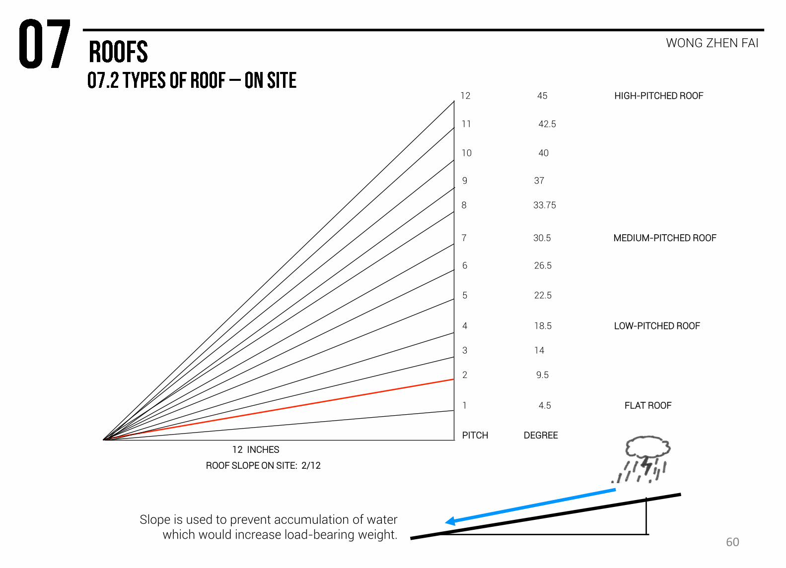
ROOF SLOPE ON SITE: 2/12
12 INCHES
1 4.5 FLAT ROOF
2 9.5
4 18.5 LOW-PITCHED ROOF
3 14
5 22.5
6 26.5
PITCH DEGREE
Slope is used to prevent accumulation of water which would increase load-bearing weight.
8 33.75
9 37
10 40
11 42.5
7 30.5 MEDIUM-PITCHED ROOF
12 45 HIGH-PITCHED ROOF
60
WONG ZHEN FAI
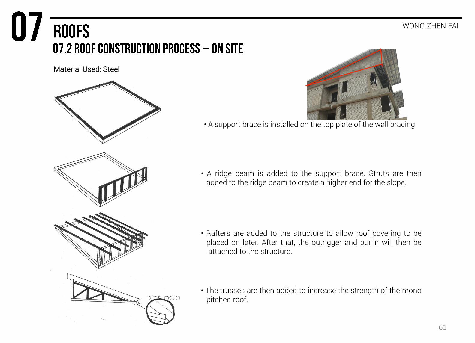
• A support brace is installed on the top plate of the wall bracing.
• A ridge beam is added to the support brace. Struts are then added to the ridge beam to create a higher end for the slope.
• Rafters are added to the structure to allow roof covering to be placed on later. After that, the outrigger and purlin will then be attached to the structure.
• The trusses are then added to increase the strength of the mono pitched roof. birds mouth
Material Used: Steel
61
WONG ZHEN FAI
STEEL RAFTERS
ALUMINIUM FOIL
ROCKWOOL
METAL DECK (ZINCULUM)
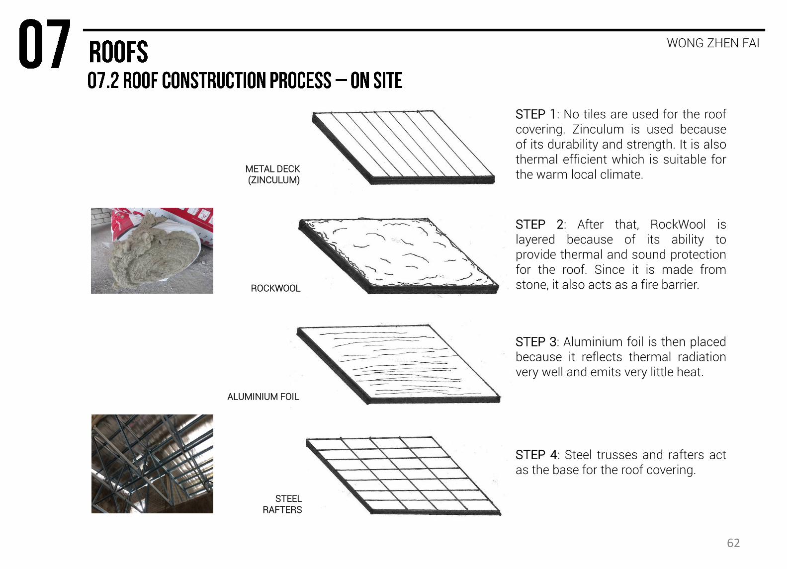
STEP 4: Steel trusses and rafters act as the base for the roof covering.
STEP 3: Aluminium foil is then placed because it reflects thermal radiation very well and emits very little heat.
STEP 2: After that, RockWool is layered because of its ability to provide thermal and sound protection for the roof. Since it is made from stone, it also acts as a fire barrier.
STEP 1: No tiles are used for the roof covering. Zinculum is used because of its durability and strength. It is also thermal efficient which is suitable for the warm local climate.
62
WONG ZHEN FAI
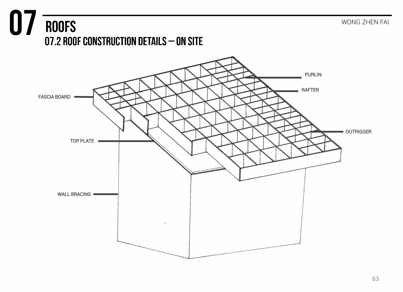
FASCIA BOARD
WALL BRACING
RAFTER
TOP PLATE
PURLIN
OUTRIGGER
63

SITE AND SAFETY
Department of Occupational Safety and Health. (n.d.). Retrieved October 19, 2015, from http://www.dosh.gov.my/index.php?lang=en Safety Handbook for Construction Site Workers. (n.d.). Retrieved October 19, 2015, from http://www.labour.gov.hk/eng/public/os/D/ConstrutionSite.pdf
PLANTS AND MACHINERY
Pascal's Principle and Hydraulics. (n.d.). Retrieved October 19, 2015, from http://www.grc.nasa.gov/WWW/K-12/WindTunnel/Activities/Pascals_principle.html Mobile cranes. (n.d.). Retrieved October 19, 2015, from http://www.liebherr.com/AT/en-GB/default_at.wfw/measure-nonMetric Nice, K. (n.d.). How Caterpillar Skid Steer Loaders & Multi Terrain Loaders Work. Retrieved October 19, 2015, fromhttp://science.howstuffworks.com/transport/engines-equipment/skid-steer.htm
Crawler Excavators. (n.d.). Retrieved October 19, 2015, from http://www.constructionequipment.com/crawler-excavators Brain, M., & Harris, T. (n.d.). Backhoes. Retrieved October 19, 2015, from http://science.howstuffworks.com/transport/engines-equipment/backhoe-loader.htm Concrete Mixers. (n.d.). Retrieved October 19, 2015, from http://www.mcneiluscompanies.com/Concrete-Mixers/concrete-mixers.html
EXTERNAL WORK & SETTING OUT AND EARTH WORK
Ching, F. (2008). Building construction illustrated. Hoboken, N.J.: John Wiley & Sons.
Chudley, R. (1973). Construction technology. London: Longman.
Elkink, A. (2010). Retaining walls | BRANZ Build. BRANZ Build. Retrieved 10 October 2015, from http://www.buildmagazine.org.nz/articles/show/retaining-walls/
Varghese, P. (2007). Building construction. New Delhi: Prentice-Hall of India.
FOUNDATION
Barkauskas, F. (2002). Foundations. In Concrete construction manual (Detail ed., p. 168). Munich, Berlin: Birkhauser.
Deep Foundation. (n.d.). Retrieved October 18, 2015, from https://en.wikipedia.org/wiki/Deep_foundation
Don's Works. (n.d.). Retrieved October 18, 2015, from http://cgetechnology.blogspot.my/2011/12/simple-method-statement.html
Foundations. (n.d.). Retrieved October 18, 2015, from http://www.concretecentre.com/technical_information/building_solutions/foundations.aspx
SUPERSTRUCTURE
BEAM AND COLUMN
Ching, F., & Adams, C. (2001). Building construction illustrated (3rd ed.). New York: Wiley.
Håvard Vasshaug,. 'Concrete Reinforcement'. N.p., 2013. Web. 20 Oct. 2015.
Reinforcing.com.au,. 'Reinforcing - Bar'. N.p., 2015. Web. 20 Oct. 2015.
SLAB
Cheah, D. (2012, January 25). Don's Works. Retrieved October 15, 2015, from http://cgetechnology.blogspot.my/2012/01/method-statement-casting-of-first-floor.html
Ching, F., & Adams, C. (2008). 4.05 - Concrete Slabs. In Building construction illustrated (4rd ed., p. 106). New York: Wiley.
Parker, H., & Ambrose, J. (1991). Simplified design of concrete structures (6th ed.). New York: Wiley.
Neufert, E. (2012). Floor Slabs. In Neufert Architects' data (Fourth ed., p. 80). Oxford: Blackwell Science.
Building Contruction I. (2015, July 13). Retrieved October 17, 2015, from http://www.slideshare.net/jernjack/building-contruction-i-50453012?ref=https://www.slideshare.net/slideshow/embed_code/key/4WmlXborUMw318
BCON Report. (2014, December 13). Retrieved October 17, 2015, from http://www.slideshare.net/eugenepeng52/bcon-report-42669612?ref=http://jsernphua.blogspot.my/2014/12/building-construction-1a-site-analysis.html
64
WALL
Brick Construction. (2005) (1st ed., pp. 1-19). North Carolina. Retrieved from http://www.pinehallbrick.com/userfiles/constructionguide_000.pdf
Ching, F., & Adams, C. (2001). Building construction illustrated. New York: Wiley.
DIY,. (2013). All About Ceiling and Wall Construction. Retrieved 18 September 2015, from http://www.diynetwork.com/how-to/rooms-and-spaces/walls-and-ceilings/all-
about-ceiling-and-wall-construction
Mishra, G. (2014). WALLS- TYPES, FEATURES AND DESIGN CONCEPT. The Constructor. Retrieved 18 September 2015, from
http://theconstructor.org/building/buildings/walls-types-features-and-design-concept/819/
Seeley, I. (1995). Building technology. Houndmills, Basingstoke: Macmillan.
STAIRCASE & DOORS
Ching, F., & Adams, C. (2001). Building construction illustrated. New York: Wiley.
Chudley, R., Greeno, R., Hurst, M., Topliss, S. (2011). Construction technology. Essex: Pearson Education Limited.
Chudley, R., Greeno, R. (2004). Advanced construction technology. Essex: Pearson Education Limited.
Neufert, E. (2012). Neufert Architects' data. Oxford: Blackwell Science.
WINDOWS
The Purpose Of A Lintel Over A Window Is To? (n.d.). Retrieved October 17, 2015, from http://home-garden.blurtit.com/808962/the-purpose-of-a-lintel-over-a-window-is-to
Ching, F., & Adams, C. (2008). 8.22 - Window Elements. In Building construction illustrated (4th ed., p. 293). New York: Wiley.
Parker, H., & Ambrose, J. (1991). Simplified design of concrete structures (6th ed.). New York: Wiley.
Neufert, E. (2012). Glass. In Neufert Architects' data (Fourth ed., p. 104). Oxford: Blackwell Science.
Neufert, E. (2012). Windows. In Neufert Architects' data (Fourth ed., p. 96). Oxford: Blackwell Science.
Building Contruction I. (2015, July 13). Retrieved October 17, 2015, from http://www.slideshare.net/jernjack/building-contruction-i-50453012?ref=https://www.slideshare.net/slideshow/embed_code/key/4WmlXborUMw318
BCON Report. (2014, December 13). Retrieved October 17, 2015, from http://www.slideshare.net/eugenepeng52/bcon-report-42669612?ref=http://jsernphua.blogspot.my/2014/12/building-construction-1a-site-analysis.html
ROOFS
Roof Styles. (n.d.). Retrieved October 18, 2015, from http://www.roofapedia.com/Roof-Info-Centre/1/Roof-Styles.aspx
(n.d.). Retrieved October 18, 2015, from http://encyclopedia2.thefreedictionary.com/mono-pitched roof
Parker Roofing. (n.d.). Retrieved October 18, 2015, from http://parkerroofing.net/what-is-a-mono-pitched-roof/
The Product Types Ontology: Class Definition for "Mono-pitched roof" (n.d.). Retrieved October 18, 2015, from http://www.productontology.org/id/Mono-pitched_roof
Roof system types. (n.d.). Retrieved October 18, 2015, from http://www.everybodyneedsaroof.com/roof-system-types
65