building a pocket-sized muon detector and starting by
TRANSCRIPT

BUILDING A POCKET-SIZED MUON DETECTOR AND STARTING
A COSMIC RAY RESEARCH GROUP
by
Hannah Powell Chesley
A senior thesis submitted to the faculty of
Brigham Young University - Idaho
in partial fulfillment of the requirements for the degree of
Bachelor of Science
Department of Physics
Brigham Young University - Idaho
December 2018


Copyright c© 2018 Hannah Powell Chesley
All Rights Reserved


BRIGHAM YOUNG UNIVERSITY - IDAHO
DEPARTMENT APPROVAL
of a senior thesis submitted by
Hannah Powell Chesley
This thesis has been reviewed by the research committee, senior thesis coor-dinator, and department chair and has been found to be satisfactory.
Date Kevin Kelley, Advisor
Date David Oliphant, Senior Thesis Coordinator
Date Jon Johnson, Committee Member
Date R. Todd Lines, Chair


ABSTRACT
BUILDING A POCKET-SIZED MUON DETECTOR AND STARTING
A COSMIC RAY RESEARCH GROUP
Hannah Powell Chesley
Department of Physics
Bachelor of Science
A pocket-sized muon detector was built to start a cosmic ray research oppor-
tunity for students at Brigham Young University - Idaho. The detector is one
designed by the CosmicWatch Project at the Massachusetts Institute of Tech-
nology. This paper will provide an introduction to muons and cosmic rays and
instructions to build and run the detector.


ACKNOWLEDGMENTS
I would like to thank my friends and peers for putting up with me for so
long, specifically Aileen Godfrey and Kristen Hawkins who have let me vent
to them so much these last few years. I would also like to thank those friends
that stayed up with me until 4AM to keep me company while I soldered tiny
components. Thank you to the physics faculty at Brigham Young University -
Idaho for having (slightly misplaced) faith in me. My physics family has been
the support I didn’t know I needed, and I could not have asked for anything
better.


Contents
Table of Contents xi
List of Figures xiii
1 Introduction 11.1 The particle of interest . . . . . . . . . . . . . . . . . . . . . . . . . . 1
1.1.1 What are muons . . . . . . . . . . . . . . . . . . . . . . . . . 11.1.2 Sources of muons . . . . . . . . . . . . . . . . . . . . . . . . . 21.1.3 Importance of muons in nuclear and particle physics research . 3
1.2 Methods and use of detection . . . . . . . . . . . . . . . . . . . . . . 51.3 The CosmicWatch Project . . . . . . . . . . . . . . . . . . . . . . . . 6
1.3.1 What is CosmicWatch? . . . . . . . . . . . . . . . . . . . . . . 61.3.2 Notable measurements . . . . . . . . . . . . . . . . . . . . . . 71.3.3 Goals of this project . . . . . . . . . . . . . . . . . . . . . . . 8
2 The detector 112.1 Supplies . . . . . . . . . . . . . . . . . . . . . . . . . . . . . . . . . . 112.2 PCB Boards . . . . . . . . . . . . . . . . . . . . . . . . . . . . . . . . 122.3 SiPM . . . . . . . . . . . . . . . . . . . . . . . . . . . . . . . . . . . . 132.4 Plastic Scintillator . . . . . . . . . . . . . . . . . . . . . . . . . . . . 142.5 Setup . . . . . . . . . . . . . . . . . . . . . . . . . . . . . . . . . . . . 15
3 Results 19
4 Conclusion and Future Work 23
Bibliography 25
A Appendix 27
B Appendix 33
xi


List of Figures
1.1 Standard Model of Particle Physics . . . . . . . . . . . . . . . . . . . 21.2 Cross-section of the LHC . . . . . . . . . . . . . . . . . . . . . . . . . 61.3 Super-Kamiokande Data . . . . . . . . . . . . . . . . . . . . . . . . . 81.4 Muon Anugular Distribution . . . . . . . . . . . . . . . . . . . . . . . 9
2.1 Unpopulated PCB boards . . . . . . . . . . . . . . . . . . . . . . . . 122.2 Plastic Scintillator . . . . . . . . . . . . . . . . . . . . . . . . . . . . 152.3 Main PCB board: Side 1 . . . . . . . . . . . . . . . . . . . . . . . . . 162.4 Main PCB board: Side 2 . . . . . . . . . . . . . . . . . . . . . . . . . 172.5 Bare detector . . . . . . . . . . . . . . . . . . . . . . . . . . . . . . . 182.6 Finished detector . . . . . . . . . . . . . . . . . . . . . . . . . . . . . 18
3.1 First data run: counts per second . . . . . . . . . . . . . . . . . . . . 203.2 Second data run: counts per second . . . . . . . . . . . . . . . . . . . 203.3 First data run: SiPM voltage per count . . . . . . . . . . . . . . . . . 213.4 Second data run: SiPM voltage per count . . . . . . . . . . . . . . . . 21
A.1 Circuit schematic for the PCBs . . . . . . . . . . . . . . . . . . . . . 29
xiii


Chapter 1
Introduction
1.1 The particle of interest
1.1.1 What are muons
The Standard Model lists and categorizes the elementary particles that make up every-
thing in the known universe. The particles are categorized into elementary fermions
and bosons, which are sub-categorized into leptons and quarks and into gauge bosons
and scalar bosons respectively. (See Figure 1.1.) There are three generations of lep-
tons, generation meaning each has the same properties as the others except for mass.
There are also three generations of quarks which are also numbered by increasing
mass.
The leptons consist of electrons, muons, tauons, and their respective neutrinos.
The electron is the lightest charged particle and is stable (it does not decay nor does
it have a lifetime restriction), while the muon and the tauon are more massive and
have short lifetimes. The muon is considered a second generation charged lepton,
it being more massive than the electron (first generation) but less massive than the
tauon (third generation). The mass of the muon is about 207me and is sometimes
1

2 Chapter 1 Introduction
Figure 1.1 The Standard Model of elementary particle physics consists offermions and bosons. The fermions are subcategorized into quarks and lep-tons, and the bosons are subcategorized into gauge bosons and scalar bosons.Source: Fermilab
referred to as a heavy or fat electron.
Since its discovery, the muon has been a major contributer to physics research.
Muons are a common occurrence in astrophysics and solar physics as they are found in
cosmic rays. The muon has helped physicists refine particle classification and develop
a better understanding of special relativity. Muons are not as affected as electrons in
electromagnetic fields due to the high mass of the muon, which allows it to penetrate
deeper into matter.
1.1.2 Sources of muons
A common decay product of a pi meson is a muon, so most experiments or interactions
that produce pi mesons will likely result in muons. These can include high energy

1.1 The particle of interest 3
interactions with normal matter and some particle accelerator experiments that use
hadrons, both of which can be very expensive to run. Muons also come from cosmic
rays which are a free source of the particle.
The most natural form in which muons come is that of cosmic rays, which is the
high energy radiation from the universe (the rays mostly come from outside of our
solar system). As the rays interact with earth’s atmosphere, pi mesons are produced
which, in turn, decay into muons. These muons are still carrying that high energy
and are traveling at relativistic speeds, hence their relativistic behavior.
Being relatively massive particles, muons are not stable particles. Their average
lifetime is approximately 2.2µs, which is quite long in subatomic terms. When trav-
eling with a velocity near the speed of light, there are two concepts that affect the
muon’s lifetime and travel: time dilation and length contraction. With time dilation,
the muon relative to the Earth has a longer lifetime than in non relativistic circum-
stances. Length contraction can make the path to Earth’s surface and beyond seem
shorter to the muon. Both of these concepts can explain the ability of the muon to
travel a great distance, even with such a short lifetime.
1.1.3 Importance of muons in nuclear and particle physics
research
The muon contributed to the refinement of particle classification, specifically with
mesons. When the muon was first detected, it was thought to be the predicted pi
meson, but scientists realized that the particle they had detected did not fit all the
predicted parameters. The mass of the muon led scientists to classify it as a meson,
because at the time, if a particle was classified as a meson, it was because of its
massiveness. With the inconsistency of the properties of the muon compared to the

4 Chapter 1 Introduction
predicted pi meson, it was determined that the defining characteristic of mesons was
that they were made of quark-anitquark pairs, unlike the muon.
The muon played a significant role in the experimental testing of time dilation. At
the time of the Rossi-Hall experiment[10], muons were still known as mesons. Rossi
and Hall used the high speed muons in the atmosphere (traveling at about 0.99c) to
qualitatively confirm time dilation and relativistic momentum. It was the first time
that special relativity’s time dilation was observed.
Muonic atoms, which consist of a muon replacing an electron in an atom, have
been studied for a few decades. Some isotopes that replace an electron with a muon
have an increase in mass which effects how it interacts with other atoms or particles.
Positive muons, though much harder to capture, have been used in experimentation
as well. The lightest hydrogen isotope is known as muonium[5], and it consists of an
electron orbiting a positive muon, making the muon the nucleus.
One interesting use for electron-positron annihilation in accelerators is in quantum
chromodynamics[7] (a theory in particle physics that discusses the strong interaction
between quarks and gluons). The annihilation can produce muons and the relation-
ship between that interaction and the electron-positron interaction that produces
quark jets has been used to learn more about quark flavor and behavior.
Tracking muons through material can help map the internal configuration of rocky
or dangerous structures. Muon transmission imaging has helped discover hidden
chambers in the pyramids of Egypt [8] and determine depths of underground tunnels
[6] that need addressing but may be too sensitive for invasive measurement. Magma
chambers are mapped as well using muon transmission imaging. Mapping the magma
chambers aids in predicting volcanic eruptions. A notable project is the Mu-Ray
project by the Italian National Institute for Nuclear Physics, which is dedicated to
mapping the chambers inside Mount Vesuvius in the hopes of predicting its next

1.2 Methods and use of detection 5
eruption.[3]
1.2 Methods and use of detection
One form of particle detection involves a scintillator with an electronic light sensor.
A scintillator is a material that exhibits scintillation (a luminescent property) when
hit with radiation, or in other words, a material that can glow when hit with ionizing
radiation. An electronic light sensor is placed near the scintillator to detect the
scintillation and absorb and re-emit it as electrons by way of the photoelectric effect.
The electrons create an electrical pulse from which useful information about the
radiation energy can be obtained.
There are several different types of scintillators that include crystals, liquids, and
plastics. The demand for plastic scintillators is increasing due to their relatively cheap
cost and ability to be shaped. Crystal scintillators are difficult to grow and machine,
while liquid scintillators do not keep their shape and therefore can yield inconsistent
results.
For electronic light sensors, photomultiplier tubes (PMTs) are known for their
use in particle detection, however they are large and expensive. Photodiodes are
similar to PMTs but are much smaller and silicon photodiodes are good for detecting
excitation energies of charged particles. Silicon photomultipliers are made up of many
silicon photodiodes to increase detection accuracy.
Particle accelerators like the Large Hadron Collider (LHC) or the Tevatron have a
series of detectors surrounding the particle beam line that filter through the products
from the collision. In Figure 1.2, a wedge of a cross-section of the Compact Muon
Solenoid (CMS) detector at the LHC can be seen that shows the layers of detectors.
The muon detector is the outermost layer shown. As mentioned before, the mass of

6 Chapter 1 Introduction
Figure 1.2 A wedge of a cross-section of the Compact Muon Solenoid (CMS)that shows the layers of detectors used in experiments. The first layer outsidethe beam line is the silicon tracker, followed by the electromagnetic calorime-ter which detects photons and electrons. The hadron calorimeter is the nextlayer which detects hadrons like pions or neutrons. The superconductingsolenoid is part of the accelerator design needed to keep the beam on theright path. A series of muon detectors makes up the final layer called muonchambers. Source: CERN
the muon allows it to travel further into material without interacting as much as an
electron might. Given this, any signal picked up outside of the magnet must be a
muon. The detector consists of iron return yokes and muon chambers.
1.3 The CosmicWatch Project
1.3.1 What is CosmicWatch?
With muon detection being so prevalent to particle physics research, it is important for
undergraduate students to be exposed to it as early as possible. Hands-on experience
with detectors would be an ideal scenario, but that could be expensive and take up
a lot of lab room. Students, particularly those at non-research institutions where

1.3 The CosmicWatch Project 7
funding is more limited, could benefit greatly from the experience gained through
building a low-cost compact muon detector.
The CosmicWatch Project was started by Spencer Axani[9], a PhD student at
the Massachusetts Institute of Technology (MIT), to provide an inexpensive research
opportunity with cosmic ray detection. The device is made to detect muons in cosmic
rays, which can appeal to students interested in astrophysics or particle physics. The
project is in collaboration with the National Centre of Nuclear Research in Warsaw,
Poland.
Building the muon detector, which is about the size of a standard box of matches[9],
consists of populating circuit boards, programming an Arduino Nano, and collecting
and analyzing data. It can also include machining and polishing material that re-
quires a smooth reflective surface, but that was not performed for this work and is
only mentioned as a possible side project for any future work.
CosmicWatch was created as a way to get university students excited about re-
search and to explore a variety of different skills. The cost per detector is estimated
at 100 U.S. dollars[2], a cost determined by buying supplies in bulk. The design of
the detector made it vastly less expensive than typical particle or muon detectors. A
big part of the cost difference was in the use of a silicon photomultiplier instead of a
photomultiplier tube, which are often large and expensive.
1.3.2 Notable measurements
The detector was not originally going to be mass marketed as an educational tool.[1] It
started off as a project for the IceCube neutrino experiment. Fermilab’s MiniBooNE
neutrino experiment uses similar devices, but in their case they are calibration scin-
tillator cubes.
To demonstrate the detector’s ability to discern between radiogenic backgrounds

8 Chapter 1 Introduction
Figure 1.3 (Left) Data collected from three different locations in and aroundthe Super-Kamiokande detector. (Right) The ACD value for the master andthe slave.[1]
and cosmic ray muons, two detectors were taken to the Super-Kamiokande detector
to collect SiPM voltage measurements. The detectors were used in a master-slave
configuration (which will be explained in a later chapter) and data was collected in
three locations: underground in the mine near the large detector, outside of the mine,
and in an airplane. Figure 1.3 shows the data collected.
Two detectors were used to measure and test muon angular distribution. The
angular distribution is said to obey a cosine squared dependence[4]. The detectors
were put in coincidence (connected through the audio jack) and placed back-to-back
on a meter long bar which was then placed at different angles to the wall. Figure 1.4
shows the data collected for the configuration. The data from the detectors fit the
cosine squared curve fairly well.
1.3.3 Goals of this project
The goal for the project discussed in this paper is to get students at Brigham Young
University - Idaho (BYU-Idaho) involved in the CosmicWatch collaboration. There
is an ever increasing demand for affordable research projects at BYU-Idaho, and
particle research is underrepresented. Starting a cosmic ray research group at BYU-

1.3 The CosmicWatch Project 9
Figure 1.4 Data collected from testing the muon detector by measuring themuon angular distribution shown against the known dependence of cos2θ.
Idaho would provide an opportunity for students to learn and develop new skills and
to be a part of something bigger.
To accomplish this goal, I built a muon detector and compiled all information
required to build it. The detector is available for use by any student interested in
research experience pertaining to particle detection.
This paper only introduces the possibilities of the pocket-sized muon detector. It
will act as an instruction guide for future students at BYU-Idaho, especially those
interested in particle and astroparticle physics. They can build upon this work which
will introduce the university’s first working muon detector.

10 Chapter 1 Introduction

Chapter 2
The detector
2.1 Supplies
The supplies to build the muon detector are listed on the CosmicWatch website[9]
and also mentioned in papers published pertaining to the project. The detector con-
sists of three PCB (polychlorinated biphenyl) circuit boards, a silicon photomultiplier
(SiPM), plastic scintillator, the casing, and various electronic components. All the
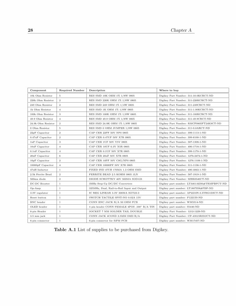
supplies needed for on detector are listed in Appendix A.
The PCB circuit boards are custom designed by the CosmicWatch project. The
SiPM is the component that actually detects the energy of the muons. The plastic
scintillator aids the SiPM by glowing in a certain range of wavelengths. (The light
emitted from the scintillator is what the SiPM reads.)
All other components are used to make reference measurements, reduce back-
ground noise and combine and store all measurements made. Some of these include
the temperature sensor, the SD card socket, the Arduino Nano, the OLED screen,
and various resistors and capacitors. The Arduino Nano was chosen for the detector
because it does a lot the conversions and measurements needed at an inexpensive cost
11

12 Chapter 2 The detector
Figure 2.1 Unpopulated PCB boards showing silkscreens.
compared to building separate circuits to perform each individual function.
2.2 PCB Boards
There are three PCB boards: one for the SD card reader, one for the SiPM (explained
further in Section 2.3), and the other is the main board with the Arduino Nano. The
boards are purchased through Elecrow, which offers custom made PCB boards. The
company uses Gerber files that the purchaser attaches to the order. The Gerber .zip
file can be found on the CosmicWatch GitHub account.
The PCB for the SD card reader mainly consists of the SD card socket for micro
SD cards, the non-inverting buffer, and the 3.3V regulator. The non-inverting buffer
and the 3.3V regulator both help control the voltage in the circuit. The micro SD
card socket writes the data onto the card. Writing to a micro SD card is optional. The
Arduino code must allow for this option in order for the micro SD PCB to operate.
The main way to record the data is to connect the detector directly to a computer,
which was the method used for this project.
The main PCB connects the micro SD PCB and the SiPM PCB and contains

2.3 SiPM 13
the Arduino Nano, temperature sensor, OLED screen, and the external connector
sockets. The BNC connection is for connecting the detector to an oscilloscope and
the audio jack is to put two detectors in coincidence. The main PCB also contains
the circuit components for data amplification, peak detection, and the VCC filtering
(used to reduce data noise).
2.3 SiPM
The SiPM PCB is arguably the most important part of the muon detector since this
PCB is what does the actual detecting. The SiPM is the device on the circuit that
senses the light that will emanate from the plastic scintillator. The SiPM that was
used was purchased from Sensl.
The SiPM is soldered to the PCB and the plastic scintillator is placed on top of
the SiPM. It is very important that there is sufficient pressure between the plastic
scintillator and the SiPM, but not too much pressure that would cause the SiPM to
crack. The pressure is needed to help ensure that the SiPM does not pick up outside
light sources.
To further ensure a light-tight enclosure, prior to being placed onto the SiPM, the
plastic scintillator should be almost fully encased in aluminum foil (there should be
as little crinkles as possible in the foil) which should be fixed with electrical tape.
There should be a space in the foil wrapping larger than the SiPM so that the foil
does not touch the SiPM (the actual component, not the PCB board). Once the
foil is in place, the plastic scintillator can be placed onto the SiPM (optical gel or
petroleum jelly can be used in between the two surfaces to further ensure connection).
Electrical tape is then used to encase the entire SiPM PCB with the exception of the
connection sites to mount the SiPM PCB to the main PCB.

14 Chapter 2 The detector
2.4 Plastic Scintillator
A plastic scintillator is a special polymer that glows within a certain range of wave-
lengths. The glow range is also referred to as the peak range, as in the range within
which the plastic shows a reaction. The ability for the plastic scintillator to reflect as
much as possible is highly important. The sides of the scintillator must be smooth
to ensure high reflection of the light so that the SiPM can sense it as accurately as
possible.
Machining and polishing the plastic scintillator is a possible addition to the
project, though it was not done during this experiment. The scintillator used for
this detector (see Figure 2.2) was purchased from Eljen Technology and was from
their EJ-200 line. The dimensions needed for the detector are 5cm × 5cm × 1cm and
needs to be machined for four 18-8 5/16” screws. The scintillator then needs to be
polished; there are many papers and videos demonstrating how to do this. Eljen
Technology offers machining and polishing for extra costs and there are other com-
panies that will make similar offers. Eljen is a popular choice especially among those
that are building the CosmicWatch muon detectors; I found that Eljen already had
scintillators machined and polished to the required specifications and were ready to
ship.
In order for the detector to be sensitive to muons, the plastic scintillator needs to
peak in the 400nm-430nm range. This range means the scintillator will emit a violet-
blue glow. The light-tight enclosure of aluminum foil and electrical tape ensures
the SiPM can pick up the the light emanating from the scintillator with minimal
background noise.

2.5 Setup 15
Figure 2.2 The plastic scintillator used and purchased from Eljen Technol-ogy’s EJ-200 line of plastic scintillators. This scintillator’s peak wavelengthis 425nm.
2.5 Setup
Populating the PCB boards requires surface mount soldering of small components,
some of which are expensive and caution should be used when soldering them. As with
all soldering, a good connection of the solder between the component and the con-
ductive spacing for the component on the board is important. The circuit schematic
and the reference sheet for populating the boards can be found in Appendix A.
There are a couple of checks that can be made to ensure there are good connec-
tions. On the SiPM PCB board, a multimeter can be used to check that there is
current one way but not the other, as the direction matters for the SiPM. On the
main PCB board, there is a check for the voltage across the SiPM connection; the
voltage should not exceed 29.4V. The voltage I was getting across was about 0.4V. I
quadruple checked the connections and nothing changed. The voltage difference does
not seem to make a difference in the data.
Connecting the three PCB boards is made easy by the silkscreens that are printed

16 Chapter 2 The detector
Figure 2.3 One side of the main PCB board that includes the OLED screenconnection and the SD card PCB connection.
on the PCB boards (the silkscreens are part of the Gerber .zip file that is sent to
the manufacturer). The micro SD card PCB connects to the side of the main PCB
opposite the Arduino connection. (See Figure 2.3.) The SiPM PCB is connected on
the same side as the Arduino and the standoffs on the SiPM PCB allow for clearance
for all components. (See Figure 2.4.)
The SD card to Arduino connection comes from 2 multi-pin headers that should
come with the Arduino Nano. For the connection, a 2x4 pin header is needed, but
the Arduino Nano only comes with two 15x1 pin headers and one 2x3 pin header.
Since not all of the pins on the 15x1 pin headers are used, two pins are cut off from
one to create a 2x4 pin header with the 2x3 pin header.
A casing is included to protect the PCB boards and components. Figure 2.5 shows
the detector without the casing while Figure 2.6 shows the enclosed detector. The
casing body was purchased from Enclosures and Casings Inc. and it is from their split
body line, size 2506H-2.9”. The completed PCB board system slides into the slots on
the inside of the aluminum casing. The end plates were purchased from Elecrow (the

2.5 Setup 17
Figure 2.4 The other side of the main PCB that includes the Arduino Nanoconnection, temperature sensor, and the SiPM PCB board connection.
same company from which the PCB boards were purchased) and plates are secured
into place with screws on either end of the aluminum body.
Depending on if the user wants to use the SD card for memory storage or saving
directly to the computer, a different code would need to be uploaded to the Arduino.
If the user wants to save directly to the computer, the OLED code would be better
as the user can watch the detection live on the screen. The SD card code is needed
for saving to a micro SD card, which is better for users who have remote experiment
set-ups (example: on a weather balloon). A python code for collecting or retrieving
data, provided by CosmicWatch, has a few options for the user: (1) record data
to the computer which collects data live and creates and saves to a file, (2) copy
data from the SD card, (3) remove data files from the SD card, or (4) connect to
the CosmicWatch website to upload data to their database. (The upload to website
option did not seem to work properly and caused python to crash. As this option did
not pertain to this project, the decision was made to not use this option.)

18 Chapter 2 The detector
Figure 2.5 The detector without the aluminum casing.
Figure 2.6 The finished detector in the aluminum casing.

Chapter 3
Results
The data files created by the Arduino code contain the count, time stamp, ADC
(analog-to-digital conversion), SiPM voltage, and temperature. For each signal, the
ADC, SiPM voltage and temperature are measured and recorded. There are two
points of focus for the results; one is the counts per second and the SiPM voltage per
count.
Finding the counts per second yields whether or not there is anything being de-
tected. Figure 3.1 and Figure 3.2 show the number of counts per second for the first
and second runs respectively. The detector is clearly getting something, and given
the design of the detector, I would conclude that it is, in fact, muons.
The SiPM voltage is related to the radiation energy the scintillator absorbs. Figure
3.3 shows the SiPM voltage versus the count. There are a few peaks that imply that
there was a high energy muon detected. For example, at around 13000 counts, there
is a cluster of higher radiation which would mean higher energy muons. Figure 3.4
shows the SiPM voltage per count for the second run. The higher the SiPM voltage,
the higher the energy of the muon.
Originally, the plan for the muon detector was to fly it in conjunction with BYU-
19

20 Chapter 3 Results
Figure 3.1 Counts per second for the first data run which lasted just over2 hours. Time started at 13:27:10 MST.
Figure 3.2 Counts per second for the second data run which lasted about 1hour. Time started at 20:47:52 MST.

21
Figure 3.3 Plot of SiPM voltage per count for first run.
Figure 3.4 Plot of SiPM voltage per count for second run.

22 Chapter 3 Results
Idaho’s High Altitude Research Team (HART). While testing the detector, the bench
data was collected without problems and the both codes for the OLED and the
SD card options operated as expected, however when connected to a battery power
source, the detector would shut off after about 2 minutes. One possible explanation
for this is that the detector was not designed with a voltage source regulator in mind,
so when the source voltage drops below a certain threshold, the detector turns off.
The detector needs a constant voltage source in order to operate. Another possible
explanation for this is that the battery packs readily available turn off when they
detect a full charge. The detector would appear to the battery pack as fully charged.

Chapter 4
Conclusion and Future Work
A muon detector was built to start a research opportunity, possibly even a team,
at BYU-Idaho for students to gain more experience and interest in other areas of
physics. Now that the school has a working muon detector, students have more
research options. There are several ways that the muon project can continue at
BYU-Idaho, including continued data collection, flying the detector with HART, and
some modifications and configurations.
In order to send the detector as a payload with HART, the detector needs a
constant voltage source. A modification to the circuit or a modified battery source
could be a solution. A voltage regulator is a common electrical component that would
be helpful for the modification. Another possibility to fix the voltage source problem
is to find a battery pack that does not turn off after detecting a full charge and use
that as the power source for the detector.
CosmicWatch used the Arduino Nano because it was cheaper and faster to buy
it instead of building a similar board that would only do what is necessary. One
potential downfall is that there is not enough memory on the Arduino Nano to a run
a code that will both operate the OLED screen and write to the micro SD card. A
23

24 Chapter 4 Conclusion and Future Work
possible project would be to modify the current design to accommodate a code that
combines the two current codes. This could be done by upgrading the Arduino type
or modifying the current codes to save space.
The CosmicWatch project designed the detector so that two detectors could
be connected; they called this a Master-Slave setup. Two detectors are connected
through the audio jack which is detected by the programmed Arduino. The connec-
tion makes one detector the master and the other detector the slave. When the master
detects a specific energy, the slave is triggered to count. Essentially, the slave only
counts when the master signals it to do so. More information on the Master-Slave
setup can be found on the CosmicWatch website and also in the papers published by
them.

Bibliography
[1] Spencer N. Axani, Katarzyna Frankiewicz, and Janet M. Conrad. The cos-
micwatch desktop muon detector: A self-contained, pocket sized particle detec-
tor. Journal of Instrumentation, 13, January 2018.
[2] Spencer N. Axani, Katarzyna Frankiewicz, and Janet M. Conrad. Cosmicwatch:
The desktop muon detector instruction manual. June 2018.
[3] Franois Beauducel, Salvatore Buontempo, Luca D’Auria, Giovanni De Lellis,
Gaetano Festa, Paolo Gasparini, Dominique Gibert, G Iacobucci, Nolwenn
Lesparre, A Marotta, et al. Muon radiography of volcanoes and the challenge at
mt. vesuvius. January 2008.
[4] K. O. et al. Cosmic rays - particle data group. In Nuclear Instruments and
Methods in Physics Research Section A: Accelerators, Spectrometers, Detectors
and Associated Equipment, volume 38, page 6.
[5] Donald G. Fleming, Donald J. Arseneau, Oleksandr Sukhorukov, Jess H. Brewer,
Steven L. Mielke, George C. Schatz, Bruce C. Garrett, Kirk A. Peterson, and
Donald G. Truhlar. Kinetic isotope effects for the reactions of muonic helium
and muonium with h2. Science, 331(6016):448–450, 2011.
25

26 BIBLIOGRAPHY
[6] E. P. George. Cosmic rays measure overburden of tunnel. Commonwealth Engi-
neer.
[7] B. R. Martin. Nuclear and Particle Physics: An Introduction. John Wiley and
Sons Ltd, 2nd edition.
[8] Arab Republic of Egypt Ministry of Antiquities, Heritage Innovation Preserva-
tion, and Cairo University Faculty of Engineering. http://www.scanpyramids.
org/.
[9] P. Przewocki and K. Frankiewicz. http://www.cosmicwatch.lns.mit.edu/about.
[10] Bruno Rossi and David B. Hall. Variation of te rate of deccay of mesotrons with
momentum. The Physical Review, 59, December 1940.

Appendix A
Appendix A contains lists of supplies needed to build one detector, the circuit schematic
for all three PCB boards, and the populating reference sheets to populate the PCB
boards.
27
28 Chapter A
Component Required Number Description Where to buy
10k Ohm Resistor 5 RES SMD 10K OHM 1% 1/8W 0805 Digikey Part Number: 311-10.0KCRCT-ND
226k Ohm Resistor 2 RES SMD 226K OHM 1% 1/8W 0805 Digikey Part Number: 311-226KCRCT-ND
249 Ohm Resistor 2 RES SMD 249 OHM 1% 1/4W 0805 Digikey Part Number: 311-249CRCT-ND
1k Ohm Resistor 4 RES SMD 1K OHM 1% 1/8W 0805 Digikey Part Number: 311-1.00KCRCT-ND
100k Ohm Resistor 3 RES SMD 100K OHM 1% 1/8W 0805 Digikey Part Number: 311-100KCRCT-ND
49.9 Ohm Resistor 4 RES SMD 49.9 OHM 1% 1/8W 0805 Digikey Part Number: 311-49.9CRCT-ND
24.9k Ohm Resistor 2 RES SMD 24.9K OHM 1% 1/8W 0805 Digikey Part Number: RMCF0805FT24K9CT-ND
0 Ohm Resistor 5 RES SMD 0 OHM JUMPER 1/8W 0805 Digikey Part Number: 311-0.0ARCT-ND
22pF Capacitor 2 CAP CER 22PF 50V NP0 0805 Digikey Part Number: 399-1113-1-ND
0.47uF Capacitor 2 CAP CER 0.47UF 50V X7R 0805 Digikey Part Number: 399-8100-1-ND
1uP Capacitor 3 CAP CER 1UF 50V Y5V 0805 Digikey Part Number: 587-1308-1-ND
10uF Capacitor 4 CAP CER 10UF 6.3V X5R 0805 Digikey Part Number: 490-1718-1-ND
0.1uF Capacitor 4 CAP CER 0.1UF 50V X7R 0805 Digikey Part Number: 399-1170-1-ND
20nF Capacitor 6 CAP CER 20nF 50V X7R 0805 Digikey Part Number: 1276-2472-1-ND
10pF Capacitor 2 CAP CER 10PF 50V C0G/NP0 0805 Digikey Part Number: 1276-1109-1-ND
10000pF Capacitor 4 CAP CER 10000PF 50V X7R 0805 Digikey Part Number: 311-1136-1-ND
47uH Inductor 1 FIXED IND 47UH 170MA 1.3 OHM SMD Digikey Part Number: 490-4063-1-ND
2.5k Ferrite Bead 2 FERRITE BEAD 2.5 KOHM 0805 1LN Digikey Part Number: 587-1919-1-ND
500ma diode 2 DIODE SCHOTTKY 40V 500MA SOD123 Digikey Part Number: MBR0540CT-ND
DC-DC Booster 1 3MHz Step-Up DC/DC Converters Digikey part number: LT3461AES6#TRMPBFCT-ND
Op-Amp 1 325MHz, Dual, Rail-to-Rail Input and Output Digikey part number: LT1807IS8#PBF-ND
3.3V regulator 1 IC REG LINEAR 3.3V 300MA SOT23-3 Digikey part number: AP2210N-3.3TRG1DICT-ND
Reset button 1 SWITCH TACTILE SPST-NO 0.02A 15V Digikey part number: P12215S-ND
BNC header 1 CONN BNC JACK R/A 50 OHM PCB Digikey part number: WM5514-ND
OLED header 1 4 pin header CONN FEMALE 4POS .100” R/A TIN Digikey part number: S5440-ND
6-pin Header 1 SOCKET 7 MM SOLDER TAIL DOUBLE Digikey Part Number: 1212-1229-ND
3.5 mm jack 1 CONN JACK 4COND 3.5MM SMD R/A Digikey Part Number: CP-43515RSSJCT-ND
6-pin connector 1 6-pin connector for SiPM PCB Digikey part number: WM17457-ND
Table A.1 List of supplies to be purchased from Digikey.

29
Figure A.1 The circuit schematic for all three PCBs.

30 Chapter A
Component Required Number Description Where to buy
Standoff for SiPM PCB 2 1/8”HexSize,3/8”Length,0-80Thread Size McMasterCarr part number: 91780A027
Standoff screws Main side 4 0-80ThreadSize,5/16”Long McMasterCarr part number: 91771A056
Plastic scintillator screws 4 18-8StainlessSteel,Number 0Size,5/16”Long McMasterCarr part number: 92470A024
Non-Inverting Buffer 1 High Speed CMOS Logic Hex Non-Inverting Buffers Mouser Part Number: 595-CD74HC4050M96
LED light 1 Any color, 5 mm Amazon
Temperature Sensor 1 TMP36 analog sensor Amazon
SiPM 1 SiPM MicroFC-60035-SMT SENSL
SD card socket 1 Micro SD Memory Card Slot Holder Sockets Uxcell (Amazon or Ebay)
Plastic Scintillator 1 5x5x1 cm Plastic Scintillator (peak about 420nm) Eljen ()
PCB boards 1 Main, SD card, and SiPM PCB Elecrow
OLED Screen 1 OLED screen 4 pin Amazon
Optical gel ¡1mL Petroleum jelly works as well Amazon
Black electrical tape as needed For wrapping scintillator Amazon
Coincidence cable as needed For connecting two detectors Amazon
BNC cable as needed For connecting detector to oscilloscope Amazon
Tin or Aluminum Foil about 100cm2 For wrapping scintillator local
Aluminum Case 1 Aluminum casing, split body, 2506-2.9” Enclosures and Cases Inc.
Front and back plates 1 set plastic end plates Elecrow
LED holder 1 LED light mounting holder Amazon
Arduino Nano 1 ATmega328 CH340G Amazon
2x3 header 1 2x3 pin header Comes with Arduino Nano
15x1 header 2 15x1 pin header Comes with Arduino Nano
Table A.2 List of supplies that are to be purchased from other suppliers.

31
Component Code What is it Description Comment
R1 10k RES SMD 10K OHM 1% 1/8W 0805
R2 226k RES SMD 226K OHM 1% 1/8W 0805
R3 249 RES SMD 249 OHM 1% 1/4W 0805
R4 1k RES SMD 1K OHM 1% 1/8W 0805
R5 10k RES SMD 10K OHM 1% 1/8W 0805
R6 100k RES SMD 100K OHM 1% 1/8W 0805
R7 100k RES SMD 100K OHM 1% 1/8W 0805
R8 1k RES SMD 1K OHM 1% 1/8W 0805
R9 Short RES SMD 0 OHM JUMPER 1/8W 0805 Short
R10 NS
R11 49.9 RES SMD 49.9 OHM 1% 1/8W 0805
R12 49.9 RES SMD 49.9 OHM 1% 1/8W 0805
R13 49.9 RES SMD 49.9 OHM 1% 1/8W 0805
R14 NS
R15 1k RES SMD 1K OHM 1% 1/8W 0805
R16 10k RES SMD 10K OHM 1% 1/8W 0805
R17 Short RES SMD 0 OHM JUMPER 1/8W 0805 Short
R18 NS
R19 NS
R20 10k RES SMD 10K OHM 1% 1/8W 0805
R24 24.9k RES SMD 24.9K OHM 1% 1/8W 0805
R25 NS
D1 500ma diode DIODE SCHOTTKY 40V 500MA SOD123 Has direction
D2 500ma diode DIODE SCHOTTKY 40V 500MA SOD123 Has direction
L1 47uH FIXED IND 47UH 170MA 1.3 OHM SMD
L2 2.5k Ferrite Bead FERRITE BEAD 2.5 KOHM 0805 1LN
C1 22pF CAP CER 22PF 50V NP0 0805
C2 0.47uF CAP CER 0.47UF 50V X7R 0805
C3 1uF CAP CER 1UF 50V Y5V 0805
C4 10uF CAP CER 10UF 6.3V X5R 0805
C5 0.1uF CAP CER 0.1UF 50V X7R 0805
C6 20nF CAP CER 20nF 50V X7R 0805
C7 10.0pF CAP CER 10PF 50V C0G/NP0 0805
C8 10 nF CAP CER 10000PF 50V X7R 0805
C9 10 nF CAP CER 10000PF 50V X7R 0806
C10 10 nF CAP CER 10000PF 50V X7R 0807
C11 10 nF CAP CER 10000PF 50V X7R 0808
C14 Short RES SMD 0 OHM JUMPER 1/8W 0805 Short
C15 0.1uF CAP CER 0.1UF 50V X7R 0805
C16 10uF CAP CER 10UF 6.3V X5R 0805
C17 0.1uF CAP CER 0.1UF 50V X7R 0805
C18 1uF CAP CER 1UF 50V Y5V 0805
Table A.3 The populating reference sheet to use as guide for the circuitschematic for the resistors and capacitors. The table lists the componentlabel from the schematic, the value of the component, and the description ofthe component.

32 Chapter A
Component Code What is it Description Comment
U1 LT3461 3MHz Step-Up DC/DC Converters Has direction
U2 LT1807IS8#PBF 325MHz, Dual, Rail-to-Rail Input and Output, Precision Op Amps Has direction
U7 NS
U6 3.3V regulator IC REG LINEAR 3.3V 300MA SOT23-3 Has direction
U8 SD card socket SMT SMD Cell Phone TF Micro SD Memory Card Slot Holder Sockets
U10 Non-Inverting Buffer High Speed CMOS Logic Hex Non-Inverting Buffers Has direction
Reset Reset button SWITCH TACTILE SPST-NO 0.02A 15V
2x4 SD header 2x3 header +2x1 header for mounting SD card PCB. 2x3 + 1x2
15x1 header 15x1 header 2x headers for mounting Arduino
Arduino Nano Arduino Nano 16 MHz CH340/ATmega328P Arduino Nano
BNC receptacle BNC header CONN BNC JACK R/A 50 OHM PCB
OLED header 4 pin header CONN FEMALE 4POS .100” R/A TIN Bottom
LED LED light Any color, 5mm
6-pin Header 6-pin Header SOCKET 7 MM SOLDER TAIL DOUBLE
3.5 mm jack 3.5mm jack CONN JACK 4COND 3.5MM SMD R/A
Temp TMP36 Temperature Sensors TMP36 Precision Linear Analog Output
SiPM1 SiPM SiPM MicroFC-60035-SMT Has direction
SiPM PCB 6-Pin 6-pin Pins WM17457-ND
Table A.4 The populating reference sheet to use as guide for the circuitschematic for all other components. The table lists the component labelfrom the schematic, the value of the component, and the description of thecomponent.

Appendix B
With the way the data files are written from the detector, a code was needed to
convert the data to counts per second from information per count. The following is
the code to convert the raw data files.
#!/bin/python2
#
# Program to convert CosmicWatch output files to count rate per interval.
#
# This program requires two command line arguments:
#
# (1) The path/name of the CosmicWatch file to be converted, and
# (2) The time interval to use in the conversion, in ms.
#
# Output is written to the terminal.
import sys
# Check the command line arguments.
33

34 Chapter B
if len(sys.argv)<3:
sys.stderr.write("You must specify by command line arguments:\n")
sys.stderr.write(" (1) The path/name of the CosmicWatch file to be"
+"converted, and\n")
sys.stderr.write(" (2) The time interval to use in the conversion,"
+"in ms.\n")
sys.exit(1)
filename=sys.argv[1]
interval=int(sys.argv[2])
print "# \""+filename+"\" -> count rate per "+str(interval)+" ms."
print "# First column is the upper bound of the interval, in ms."
print "# Second column is the number of counts in the interval."
# Open the file and read the data (the arduino time).
try:
times=set()
datafile=open(filename,"r")
for i in range(6): datafile.readline() # Skip first five lines
line=datafile.readline()
while line: # Read line by line, storing the arduino time
times.add(int(line.split()[3]))
line=datafile.readline()

35
except:
sys.stderr.write("Error encountered reading file \""+filename+"\".\n")
sys.exit(2)
finally:
datafile.close()
# Now process the times array into the desired data format.
count=1
while len(times)>0:
tmax=count*interval
inthis=set([i for i in times if i<=tmax])
print "%15d %15d" % (tmax,len(inthis))
times=times-inthis
count=count+1

36 Chapter B