bscanmataryia22
TRANSCRIPT


B-Scan UltrasonographyBy
Mohamed Abdel-AzizM.Sc.,Egy.Fellowship,ICO

INTRODUCTION
-Ophthalmic ultrasonography is a safe, noninvasive
diagnostic tool that provides instant feedback for
the evaluation of various ophthalmic disorders.
-Diagnostic ophthalmic ultrasonography is most useful
in the presence of opaque ocular media caused by
corneal opacities, anterior chamber opacities, cata-
racts,or vitreous hemorrhage.
-Intraocular tumors are routinely documented,
measured, and differentiated by ultrasonographic
techniques

BASIC PHYSICS
-The maximum range of human hearing includes sound
frequencies from 15 to about 20,000 waves,or cycles,
per second.
-Ultrasound is an acoustic wave with a frequency
above the audible range .
-Frequencies currently used in ophthalmic ultrasound
machines range from 8 to 80 MHz, compared with 2 to 6
MHz typically used in other fields of diagnostic
ultrasound.

-The use of higher frequencies allows for increased
resolution, which is essential in the evaluation of small
ophthalmic structures.
-Echoes are produced when ultrasound waves
encounter an interface between two materials have
different acoustic impedances.
-The greater the difference in impedance, the more
sound will be reflected rather than transmitted.


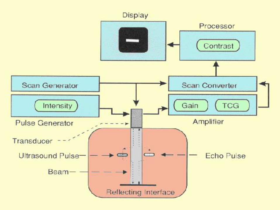
An ultrasound unit is composed of four basic
elements:
the pulser, the receiver, and the display unit are all
contained within the same chassis and connected to the
transducer, located at the tip of the probe by an
electrically shielded cable.

-The pulser produces electric pulse at a rate of 1000
pulses per second. Each pulse excites the electrodes of
the piezo-electric crystal of the transducer, generating
sound waves.
-The returning echoes are received by the transducer
and transformed into electric signals.
- These signals are processed in the receiver and
demodulator, and then displayed on the screen of the
display unit.

POSTERIOR
OCULAR SEGMENT
IMAGING

-The eye can be likened to a face of the clock, where
the top is 12 o'clock, the right side is 3 o'clock, the
bottom is 6 o'clock, and the left side is 9 o'clock.
-These points of reference are the same whether
one is performing anterior or posterior ocular segment
imaging, or scanning the right or the left eye.


WAYS TO IMAGING
THE EYE
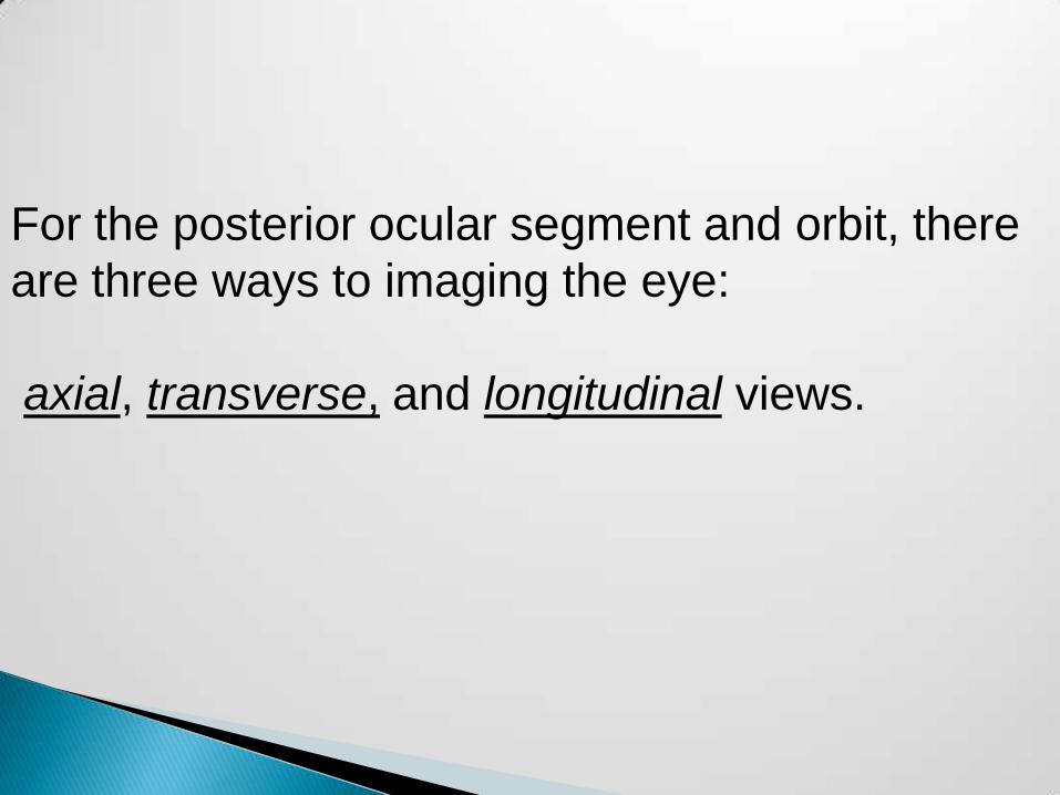
For the posterior ocular segment and orbit, there
are three ways to imaging the eye:
axial, transverse, and longitudinal views.

Axial scan : provides a pleasing, generally
understandable Picture.
1-Horizontal axial views allow simultaneous
imaging of the lens, optic nerve, and the macula.
In this view, the tip of the probe is placed at the
center of the cornea, with the marker positioned
toward the nasal side of the eye. Thus, the top of
the scan is the nasal side, while the bottom is the
temporal side.


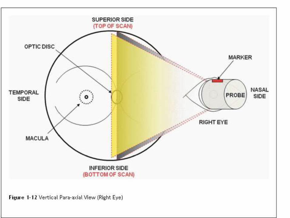
views provide simultaneous imaging of Vertical axial -2
the lens and the optic nerve.
In this view, the tip of the probe is placed at the center of
the cornea, with the marker positioned toward the
superior side of the eye. Thus, the top of the scan is the
superior side, while the bottom is the inferior side.


-One can twist the probe 45 degrees to the right or 45
of the oblique axial views degrees to the left to obtain
eye. Similar to vertical axial views, the marker is always
positioned at the superior side.
-Furthermore, one can obtain an axial view of the eye
just above or below the level of the optic nerve head, as
well as immediately to the right or to the left of it. These
of the eye.axial views -paraare termed


provide a lateral sweep of one Transverse views :-
quadrant of the fundus.
- There are as many transverse views as there are
hours in a clock.
views, the tip of the probe is horizontal transverse -
placed on the sclera below the cornea pointing up to
view the superior fundus, or on the sclera above the
cornea pointing down to view the inferior fundus. Like
the horizontal axial view, the marker is always positioned
of the eye. Thus, the top of the scan is at the nasal side
the nasal side, while the bottom is the temporal side.


views, the tip of the probe is vertical transverse -
placed on the sclera nasal to the cornea pointing toward
the opposite side of the eye to view the temporal fundus.
Alternatively, the probe is placed on the sclera temporal
to the cornea pointing toward the opposite side to view
marker . Like the vertical axial view, the fundusthe nasal
side of the eye. is always positioned at the superior
Hence, the top of the scan is the superior side, while the
bottom is the inferior side.


-In both horizontal and vertical transverse views, one
can point the probe toward the back of the eye (posterior
to the equator) to obtain a more posterior transverse
view of the fundus.
-Alternatively, one can point the probe toward the front
(anterior to the equator) to obtain a more peripheral
transverse view of the fundus.


views are essentially diagonal Oblique transverse
transverse views of the eye. Similar to vertical
transverse views, the marker is always positioned at the
superior side.

posterior -provide an anteriorLongitudinal views -
sweep of a specific meridian of the fundus.
-There are as many longitudinal views as there are
hours in a clock.
-In this view, the tip of the probe is placed on the sclera
next to the cornea pointing toward the opposite side of
the eye.
-Here, the marker is always positioned toward the
limbus. Thus, the top of the scan is the anterior
peripheral side, while the bottom is the posterior side
close to the optic nerve..


one can shift the probe away from the limbus to obtain a
more peripheral longitudinal view of a particular meridian
of the fundus


EXAMPLES OF B-
SCAN PICTURES

(A) Fresh vitreous hemorrhage. Longitudinal B-scan showing diffuse low-to-medium
reflective opacities in the vitreous cavity (arrowheads).
(B) Organized vitreous hemorrhage. Note pseudomembranous surfaces (arrowhead)
within the vitreous cavity representing the organization of blood.

.(D) Thickened PVD (arrowheads). B-scan axial view. Note lack of attachment at the optic nerve.

Total open funnel retinal detachment.(A) B-scan at low gain (49 dB) shows open funnel configuration and optic disc attachment. (B) A-scan shows 100% peak corresponding to the RD.

PVD Retinal DetachmentEchogenicity : Low-medium High
Change with gain (dB): Disappears with low gain Visible with low gain
Mobility : High Low
Optic disc attachment : Present or absent Always present

(C) Serous choroidal detachment. B-scan shows two choroidal detachments (arrowheads) with subchoroidal serous fluid (SF).(D)Hemorrhagic choroidal detachment. Note appositional or kissing choroidaldetachment (arrowheads) with dense opacities in the suprachoroidal space indicative of subchoroidal hemorrhage (SH).
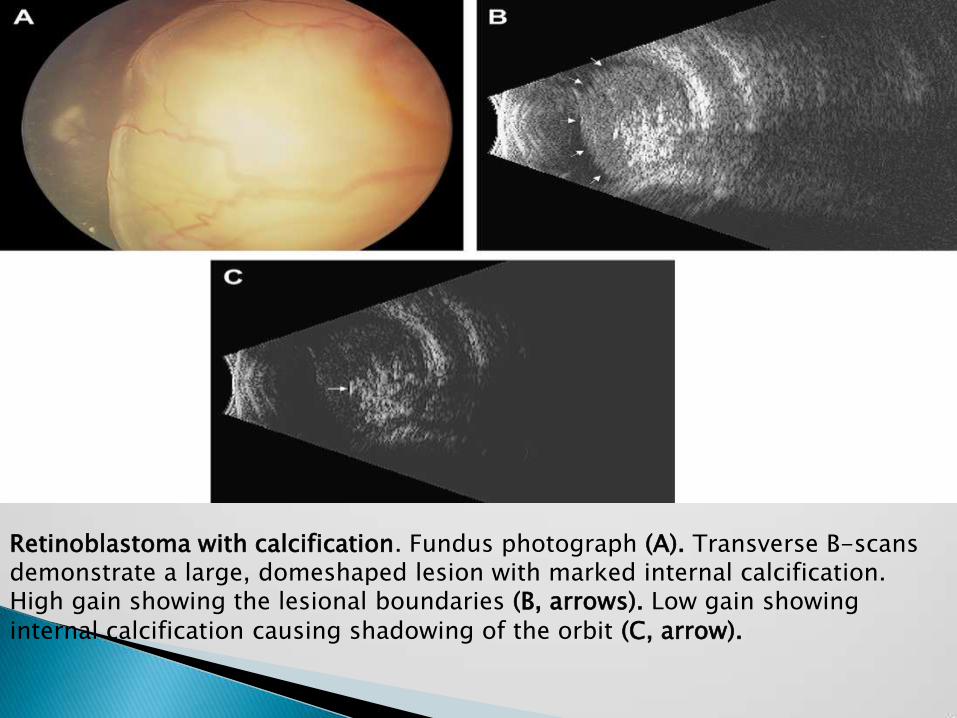
Retinoblastoma with calcification. Fundus photograph (A). Transverse B-scans demonstrate a large, domeshaped lesion with marked internal calcification. High gain showing the lesional boundaries (B, arrows). Low gain showing internal calcification causing shadowing of the orbit (C, arrow).
