brother fax 560, 580mc, t72, t74, t76, mfc-660mc service manual
TRANSCRIPT

FACSIMILE EQUIPMENT
SERVICE MANUAL
MODEL: FAX560/FAX580MC/MFC660MCFAX-T72/FAX-T74/FAX-T76

© Copyright Brother 2000
All rights reserved.
No part of this publication may be reproduced in anyform or by any means without permission in writingfrom the publisher.
Specifications are subject to change without notice.
PREFACE
This publication is a Service Manual covering the specifications, construction, theory of operation,and maintenance of the Brother facsimile equipment. It includes information required for fieldtroubleshooting and repair--disassembly, reassembly, and lubrication--so that service personnel willbe able to understand equipment function, to rapidly repair the equipment and order any necessaryspare parts.
To perform appropriate maintenance so that the facsimile equipment is always in best condition forthe customer, the service personnel must adequately understand and apply this manual.
This manual is made up of six chapters and appendices.
CHAPTER I. GENERAL DESCRIPTION
CHAPTER II. INSTALLATION
CHAPTER III. THEORY OF OPERATION
CHAPTER IV. DISASSEMBLY/REASSEMBLY AND LUBRICATION
CHAPTER V. MAINTENANCE MODE
CHAPTER VI. ERROR INDICATION AND TROUBLESHOOTING
Appendix 1. EEPROM Customizing Codes
Appendix 2. Circuit Diagrams
This manual describes the models and their versions to be destined for major countries. The specificationsand functions are subject to change depending upon each destination.

CHAPTER I.
GENERAL DESCRIPTION

CHAPTER I. GENERAL DESCRIPTION
CONTENTS
1. EQUIPMENT OUTLINE ........................................................................................ I-1
1.1 External Appearance and Weight.................................................................. I-1
1.2 Components ................................................................................................. I-1
2. SPECIFICATIONS ................................................................................................ I-2
I - 1
1. EQUIPMENT OUTLINE
1.1 External Appearance and Weight
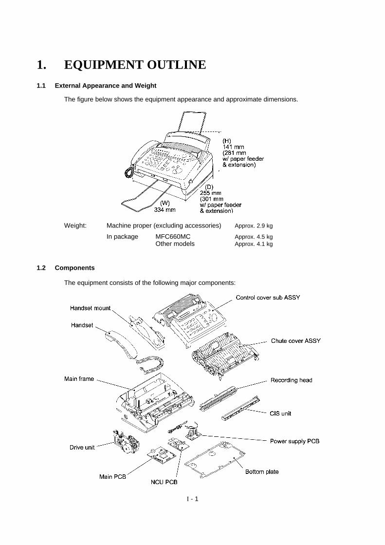
The figure below shows the equipment appearance and approximate dimensions.
Weight: Machine proper (excluding accessories) Approx. 2.9 kg
In package MFC660MCOther models
Approx. 4.5 kgApprox. 4.1 kg
1.2 Components
The equipment consists of the following major components:

I - 2
2. SPECIFICATIONS(1/2)
Model Name FAX560 FAX580MC MFC660MCEngine Thermal transfer Thermal transfer Thermal transferColor Upper: New Personal white
(1485)Lower: 1473 gray
Upper: New Personal white(1485)
Lower: 1473 gray
Upper: MFC white(1495 gray)
Lower: 1473 grayTransmission Speed (sec) 15 9 9Modem Speed (bps) 9600 14,400 14,400Group Compatibility G3 G3 G3Input/Output Width 8.5"/8.5" 8.5"/8.5" 8.5"/8.5"ADF (pages) 10 10 10Paper Feeder (sheets) Letter: 50*, Legal: 30 Letter: 50*, Legal: 30 Letter: 50*, Legal: 30Ribbon Yield (letter-size) 150 pages (47 m) 150 pages (47 m) 150 pages (47 m)Starter Ribbon Yield (letter-size) 30 pages (10 m) 30 pages (10 m) 30 pages (10 m)Replacement Roll PC401: 47 m (150 pages) PC401: 47 m (150 pages) PC401: 47m (150 pages)LCD Size 16 x 1 16 x 1 16 x 1On-Screen Programming Yes Yes YesSuper Fine Yes Yes YesSmoothing Yes Yes YesGray Scale (levels) 64 by Dithered 64 by Dithered 64 by DitheredOne Touch 4 4 4Speed Dial 50 50 50Telephone Index Yes as "Search" Yes as "Search" Yes as "Search"Speaker Phone Monitor Full duplex (digital) Full duplex (digital)Handset Yes Yes YesFAX/TEL Switch Yes Yes YesDistinctive Ring Detection Yes Yes YesCaller ID Yes Yes YesCall Waiting Caller ID Yes Yes YesTAD Interface Yes Yes YesEnhanced Remote Activation Yes Yes YesAutomatic Redial Yes Yes YesNext-FAX Reservation Yes Yes YesMulti-Resolution Transmission Yes Yes YesPolling Type Sim/Seq Sim/Seq Sim/SeqDelayed Transmission 3-timer 3-timer 3-timerCall Reservation Yes Yes YesElectronic Coverpage Yes-Super Yes-Super Yes-SuperCall Back Message Yes Yes YesActivity Report Yes Yes YesTX Verification Report Yes Yes YesMemory Capacity (pages) 512 KB
(up to 25 pages for OPR**)512 KB
(up to 25 pages for OPR**)512 KB
(up to 25 pages for OPR**)ECM Yes Yes YesBroadcasting Yes Yes YesQuick Scan Yes Yes YesOut-of-Paper Reception Yes Yes Yes
*Paper feeder: 50 sheets for US/Canada
**Page memory: 25 pages in OPR (out-of-paper reception), 22 pages in quick scan

I - 3
(1/2)
Model Name FAX-T72(Ger & Fra Only)
FAX-T74 FAX-T76
Engine Thermal transfer Thermal transfer Thermal transferColor New Personal black (1293) New Personal black (1293) New Personal black (1293)Transmission Speed (sec) 15 15 9Modem Speed (bps) 9600 9600 14,400Group Compatibility G3 G3 G3Input/Output Width 8.5"/8.5" 8.5"/8.5" 8.5"/8.5"ADF (pages) 10 10 10Paper Feeder (A4-size) 30 sheets 30 sheets 30 sheetsRibbon Yield (A4-size) 130 pages (47 m) 130 pages (47 m) 130 pages (47 m)Starter Ribbon (A4-size) Yes-10 m (30 pages) Yes-10 m (30 pages) Yes-10 m (30 pages )Replacement RollLCD Size 16 x 1 16 x 1 16 x 1On-Screen Programming Yes Yes YesSuper Fine Yes Yes YesSmoothing Yes Yes YesGray Scale (levels) 64 by Dithered 64 by Dithered 64 by DitheredOne Touch 4 4 4Speed Dial 50 50 50Telephone Index Yes as "Search" Yes as "Search" Yes as "Search"Speaker Phone Monitor Monitor Full duplex (digital)Handset No Yes YesFAX/TEL Switch Yes Yes YesCaller ID Yes
HOL/SWE/UK/IRE/ FRA/NOR/BEL/ DEN/SPA
YesHOL/SWE/UK/IRE/ FRA/
NOR/BEL/ DEN/SPA
YesHOL/SWE/UK/IRE FRA/
NOR/BEL/ DEN/SPACall Waiting Caller ID No No NoDistinctive Ring Detection Yes for DEN/UK Yes for DEN/UK Yes for DEN/UKTAD Interface Yes Yes YesEnhanced Remote Activation Yes Yes YesAutomatic Redial Yes Yes YesNext-FAX Reservation Yes Yes YesMulti-Resolution Transmission Yes Yes YesPolling Type Sim/Sec/Del/Seq Sim/Sec/Del/Seq Sim/Sec/Del/SeqDelayed Transmission 3-timer 3-timer 3-timerCall Reservation Yes Yes YesElectronic Coverpage Yes-Super Yes-Super Yes-SuperCallback Message Yes Yes YesJournal Report Yes Yes YesTX Verification Report Yes Yes YesMemory Capacity 512 KB
(up to 20 pages for OPR*)512 KB
(up to 20 pages for OPR*)512 KB
(up to 20 pages for OPR*)ECM Yes Yes YesBroadcasting Yes Yes YesQuick Scan Yes Yes Yes
*Page memory: 20 pages ITU-T No.1 chart in OPR (out-of-paper reception) in the ECM mode
I - 4
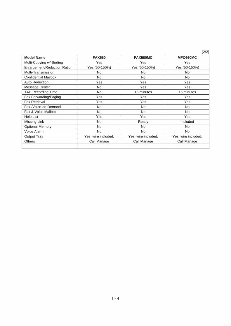
(2/2)
Model Name FAX560 FAX580MC MFC660MCMulti-Copying w/ Sorting Yes Yes YesEnlargement/Reduction Ratio Yes (50-150%) Yes (50-150%) Yes (50-150%)Multi-Transmission No No NoConfidential Mailbox No No NoAuto Reduction Yes Yes YesMessage Center No Yes YesTAD Recording Time No 15 minutes 15 minutesFax Forwarding/Paging Yes Yes YesFax Retrieval Yes Yes YesFax-/Voice-on-Demand No No NoFax & Voice Mailbox No No NoHelp List Yes Yes YesMissing Link No Ready IncludedOptional Memory No No NoVoice Alarm No No NoOutput Tray Yes, wire included. Yes, wire included. Yes, wire included.Others Call Manage Call Manage Call Manage

I - 5
(2/2)
Model Name FAX-T72(Ger & Fra Only)
FAX-T74 FAX-T76
Out-of-Paper Reception Yes Yes YesMulti-Copying w/ Sorting Yes Yes YesEnlargement/Reduction Ratio Yes (50-150%) Yes (50-150%) Yes (50-150%)Multi-Transmission No (w/o SHIFT key) No (w/o SHIFT key) No (w/o SHIFT key)Confidential Mailbox No No NoAuto Reduction Yes Yes YesMessage Manager No No YesTAD Recording Time No No 15 minutesFax Forwarding/Paging Yes-Only Fax Forwarding Yes-Only Fax Forwarding Yes-bothFax Retrieval Yes Yes YesFax-/Voice-on-Demand No No NoFax & Voice Mailbox No No NoHelp List Yes Yes YesMFL PRO for FAX No No ReadyOptional Memory No No NoMemo Manager No No NoMute Key No Yes-music on hold;
Green SleevesYes-music on hold;
Green SleevesBackup for Clock 9 hours 9 hours 15 hoursOutput Tray Not available Not available Not availableBackup for Page Memory No No 6 hoursPower Consumption Standby: Less than 2 W
Peak: 150 WStandby: Less than 2 W
Peak: 150 WStandby: Less than 2 W
Peak: 150 W
Remarks
Base models MC models
w/o handset w/ handset
American models FAX560 FAX580MC/MFC660MC
European models FAX-T72 FAX-T74 FAX-T76

CHAPTER II.
INSTALLATION

CHAPTER III.
THEORY OF OPERATION
CHAPTER III. THEORY OF OPERATION
CONTENTS
1. OVERVIEW........................................................................................................... III-1
2. MECHANISMS...................................................................................................... III-2
2.1 Scanning Mechanism.................................................................................... III-3
Automatic document feeder (ADF)................................................................ III-3
Scanner ........................................................................................................ III-3
2.2 Printing Mechanism ...................................................................................... III-3
Automatic cut sheet feeder (ACF) and registration mechanism ..................... III-3
Printing and paper ejecting mechanism......................................................... III-3
2.3 Power Transmission Switching Mechanism................................................... III-3
2.4 Sensors and Actuators .................................................................................. III-4
3. CONTROL ELECTRONICS.................................................................................. III-6
3.1 Configuration ................................................................................................ III-6

III - 1
1. OVERVIEW
*Not provided on models w/o handset.**Provided on MC models.

III - 2
2. MECHANISMS
The facsimile equipment is classified into the following mechanisms:
n Scanning Mechanism - ADF mechanism- Document scanning & feeding mechanism
n Printing Mechanism - ACF and registration mechanism- Printing and paper ejecting mechanism
n Power Transmission Switching Mechanism
n Sensors and Actuators
III - 3
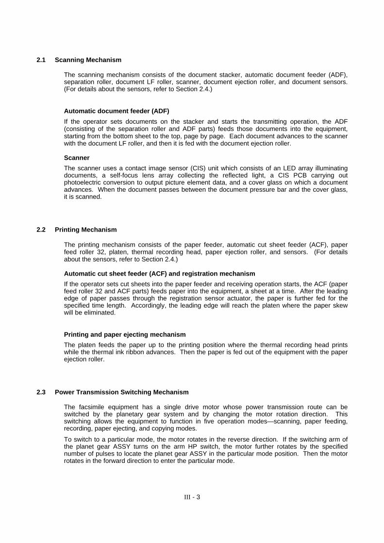
2.1 Scanning Mechanism
The scanning mechanism consists of the document stacker, automatic document feeder (ADF),separation roller, document LF roller, scanner, document ejection roller, and document sensors.(For details about the sensors, refer to Section 2.4.)
Automatic document feeder (ADF)
If the operator sets documents on the stacker and starts the transmitting operation, the ADF(consisting of the separation roller and ADF parts) feeds those documents into the equipment,starting from the bottom sheet to the top, page by page. Each document advances to the scannerwith the document LF roller, and then it is fed with the document ejection roller.
Scanner
The scanner uses a contact image sensor (CIS) unit which consists of an LED array illuminatingdocuments, a self-focus lens array collecting the reflected light, a CIS PCB carrying outphotoelectric conversion to output picture element data, and a cover glass on which a documentadvances. When the document passes between the document pressure bar and the cover glass,it is scanned.
2.2 Printing Mechanism
The printing mechanism consists of the paper feeder, automatic cut sheet feeder (ACF), paperfeed roller 32, platen, thermal recording head, paper ejection roller, and sensors. (For detailsabout the sensors, refer to Section 2.4.)
Automatic cut sheet feeder (ACF) and registration mechanism
If the operator sets cut sheets into the paper feeder and receiving operation starts, the ACF (paperfeed roller 32 and ACF parts) feeds paper into the equipment, a sheet at a time. After the leadingedge of paper passes through the registration sensor actuator, the paper is further fed for thespecified time length. Accordingly, the leading edge will reach the platen where the paper skewwill be eliminated.
Printing and paper ejecting mechanism
The platen feeds the paper up to the printing position where the thermal recording head printswhile the thermal ink ribbon advances. Then the paper is fed out of the equipment with the paperejection roller.
2.3 Power Transmission Switching Mechanism
The facsimile equipment has a single drive motor whose power transmission route can beswitched by the planetary gear system and by changing the motor rotation direction. Thisswitching allows the equipment to function in five operation modes—scanning, paper feeding,recording, paper ejecting, and copying modes.
To switch to a particular mode, the motor rotates in the reverse direction. If the switching arm ofthe planet gear ASSY turns on the arm HP switch, the motor further rotates by the specifiednumber of pulses to locate the planet gear ASSY in the particular mode position. Then the motorrotates in the forward direction to enter the particular mode.

III - 4
2.4 Sensors and Actuators
This equipment has two photosensors and five mechanical switches as described below.
Sensor name Type Located on
Document front sensor Microswitch (SEN1) Control panel PCBDocument rear sensor Microswitch (SEN2) Control panel PCB
Cover sensor Microswitch (SW2) Sensor PCBHook switch* Microswitch (SW1) Sensor PCBRegistration sensor Photosensor Sensor PCB
Ribbon sensor Photosensor Main PCB
Arm HP switch Leaf switch Drive unit
*Not provided on models w/o handset.
• Document front sensor which detects the presence of documents.
• Document rear sensor which detects the leading and trailing edges of pages to tell the controlcircuitry when the leading edge of a new page has reached the starting position and when thescan for that page is over.
• Cover sensor which detects whether the control panel ASSY is closed.
• Hook switch sensor* which detects whether the handset is placed on the handset mount.
• Registration sensor which detects the leading and trailing edges of recording paper, whichallows the controller to determine the registration timing and check paper jam.
• Ribbon sensor which detects whether the ink ribbon is loaded.
• Arm HP switch which detects whether the switching arm of the drive unit is placed in the homeposition.
The registration sensor and ribbon sensor is a photointerrupter consisting of a light-emitting diodeand a light-sensitive transistor. Each of them has an actuator separately arranged (see the nextpage). When an actuator is not activated, its black end lies in the path of light issued from thelight-emitting diode and interrupts its light so that the emitted light does not enter the light-sensitivetransistor. If paper or ribbon comes in so as to activate the actuator, the actuator's black end goesout of the light path and the emitted light enters the light-sensitive transistor. This way, the sensordetects the presence of paper or ink ribbon.

III - 5
*Not provided on models w/o handset.
Location of Sensors and Actuators

III - 6
3. CONTROL ELECTRONICS
3.1 Configuration
The hardware configuration of the facsimile equipment is shown below.
*1 On the main PCB is the ribbon sensor.*2 On the sensor PCB are these sensors:
l Cover sensor (SW2)l Hook switch* (SW1)l Registration sensor
*3 On the control panel PCB are these sensors:l Document front sensor (SEN1)l Document rear sensor (SEN2)
Configuration of Facsimile Equipment
CHAPTER IV.
DISASSEMBLY/REASSEMBLY ANDLUBRICATION
CHAPTER IV. DISASSEMBLY/REASSEMBLY AND LUBRICATION
CONTENTS
1. DISASSEMBLY/REASSEMBLY ........................................................................... IV-1
n Safety Precautions.............................................................................................. IV-1
Tightening Torque List ........................................................................................ IV-2
n Preparation ......................................................................................................... IV-3
n How to Access the Object Component ................................................................ IV-3
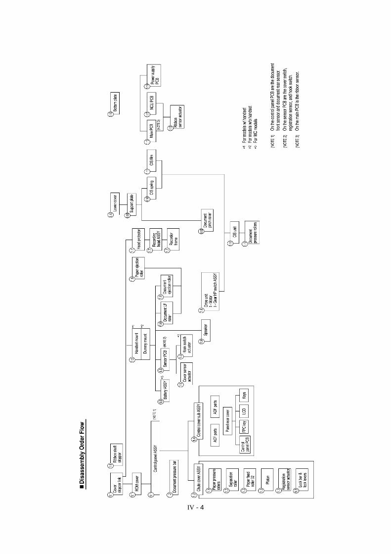
n Disassembly Order Flow ..................................................................................... IV-4
1.1 Cover Stopper Link, Ribbon Shaft Stopper, ROM Cover, and ControlPanel ASSY ................................................................................................... IV-5
1.2 Disassembly of the Control Panel ASSY (Document pressure bar and chutecover ASSY) .................................................................................................. IV-7
1.3 Disassembly of the Chute Cover ASSY (Paper pressure rollers, separationroller, paper feed roller 32, platen, registration sensor actuator, and lockbar & lock levers) ........................................................................................... IV-10
1.4 Disassembly of the Control Cover Sub ASSY (ACF parts, ADF parts, panelrear cover, control panel PCB, FPC key, LCD, and keys) ............................... IV-17
1.5 Handset Mount*1, Dummy Mount*2, Battery ASSY*3, Sensor PCB, CoverSensor Actuator, and Hook Switch Actuator*1 ................................................. IV-21
1.6 Paper Ejection Roller, Document LF Roller, and Document Ejection Roller .... IV-24
1.7 Head Protector, Recording Head ASSY, and Recorder Frame........................ IV-25
1.8 Drive Unit, Motor, and Arm HP Switch ASSY ................................................. IV-28
1.9 Speaker.......................................................................................................... IV-32
1.10 Lower Cover, Support Plate, and CIS Spring .................................................. IV-33
1.11 CIS Film and CIS Unit .................................................................................... IV-34
1.12 Document Pressure Rollers and Document Pinch Roller................................. IV-36
1.13 Bottom Plate, Main PCB, NCU PCB, Power Supply PCB, and RibbonSensor Actuator.............................................................................................. IV-38
2. LUBRICATION...................................................................................................... IV-43
[ 1 ] Separation roller and its gear and paper feed roller 32 and its gear......... IV-43
[ 2 ] Platen gear (Gear 24) and joint between gears 32 and chute coverASSY...................................................................................................... IV-44
[ 3 ] Paper ejection roller, document LF roller, and document ejection roller .. IV-45

IV - 1
1. DISASSEMBLY/REASSEMBLY
nn Safety Precautions
To prevent the creation of secondary problems by mishandling, observe the following precautionsduring maintenance work.
(1) Unplug the power cord from the power outlet before replacing parts or units. When havingaccess to the power supply, be sure to unplug the power cord from the power outlet.
(2) Be careful not to lose screws, washers, or other parts removed for parts replacement.
(3) When using soldering irons and other heat-generating tools, take care not to damage the resinparts such as wires, PCBs, and covers.
(4) Before handling the PCBs, touch a metal portion of the equipment to discharge staticelectricity; otherwise, the electronic parts may be damaged due to the electricity charged inyour body.
(5) When transporting PCBs, be sure to wrap them in conductive sheets such as aluminum foil.
(6) Be sure to reinsert self-tapping screws correctly, if removed.
(7) Tighten screws to the torque values listed on the next page.
(8) When connecting or disconnecting cable connectors, hold the connector bodies not thecables. If the connector has a lock, always slide the connector lock to unlock it.
(9) Before reassembly, apply the specified lubricant to the specified points. (Refer to Section 2 inthis chapter.)
(10) After repairs, check not only the repaired portion but also that the connectors and otherrelated portions function properly before operation checks.
IV - 2
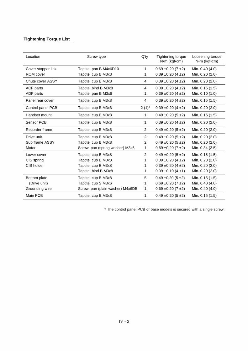
Tightening Torque List
Location Screw type Q'ty Tightening torque Loosening torqueN•m (kgf•cm) N•m (kgf•cm)
Cover stopper link Taptite, pan B M4x6D10 1 0.69 ±0.20 (7 ±2) Min. 0.40 (4.0) ROM cover Taptite, cup B M3x8 1 0.39 ±0.20 (4 ±2) Min. 0.20 (2.0)
Chute cover ASSY Taptite, cup B M3x8 4 0.39 ±0.20 (4 ±2) Min. 0.20 (2.0)
ACF parts Taptite, bind B M3x8 4 0.39 ±0.20 (4 ±2) Min. 0.15 (1.5) ADF parts Taptite, pan B M3x6 1 0.39 ±0.20 (4 ±2) Min. 0.10 (1.0)
Panel rear cover Taptite, cup B M3x8 4 0.39 ±0.20 (4 ±2) Min. 0.15 (1.5)
Control panel PCB Taptite, cup B M3x8 2 (1)* 0.39 ±0.20 (4 ±2) Min. 0.20 (2.0)
Handset mount Taptite, cup B M3x8 1 0.49 ±0.20 (5 ±2) Min. 0.15 (1.5)
Sensor PCB Taptite, cup B M3x8 1 0.39 ±0.20 (4 ±2) Min. 0.20 (2.0)
Recorder frame Taptite, cup B M3x8 2 0.49 ±0.20 (5 ±2) Min. 0.20 (2.0)
Drive unit Taptite, cup B M3x8 2 0.49 ±0.20 (5 ±2) Min. 0.20 (2.0) Sub frame ASSY Taptite, cup B M3x8 2 0.49 ±0.20 (5 ±2) Min. 0.20 (2.0) Motor Screw, pan (spring washer) M3x6 1 0.69 ±0.20 (7 ±2) Min. 0.34 (3.5)
Lower cover Taptite, cup B M3x8 2 0.49 ±0.20 (5 ±2) Min. 0.15 (1.5) CIS spring Taptite, cup B M3x8 1 0.39 ±0.20 (4 ±2) Min. 0.20 (2.0) CIS holder Taptite, cup B M3x8 1 0.39 ±0.20 (4 ±2) Min. 0.20 (2.0)
Taptite, bind B M3x8 1 0.39 ±0.10 (4 ±1) Min. 0.20 (2.0)
Bottom plate Taptite, cup B M3x8 5 0.49 ±0.20 (5 ±2) Min. 0.15 (1.5) (Drive unit) Taptite, cup S M3x6 1 0.69 ±0.20 (7 ±2) Min. 0.40 (4.0) Grounding wire Screw, pan (plain washer) M4x6DB 1 0.69 ±0.20 (7 ±2) Min. 0.40 (4.0)
Main PCB Taptite, cup B M3x8 1 0.49 ±0.20 (5 ±2) Min. 0.15 (1.5)
* The control panel PCB of base models is secured with a single screw.
IV - 3
nn Preparation
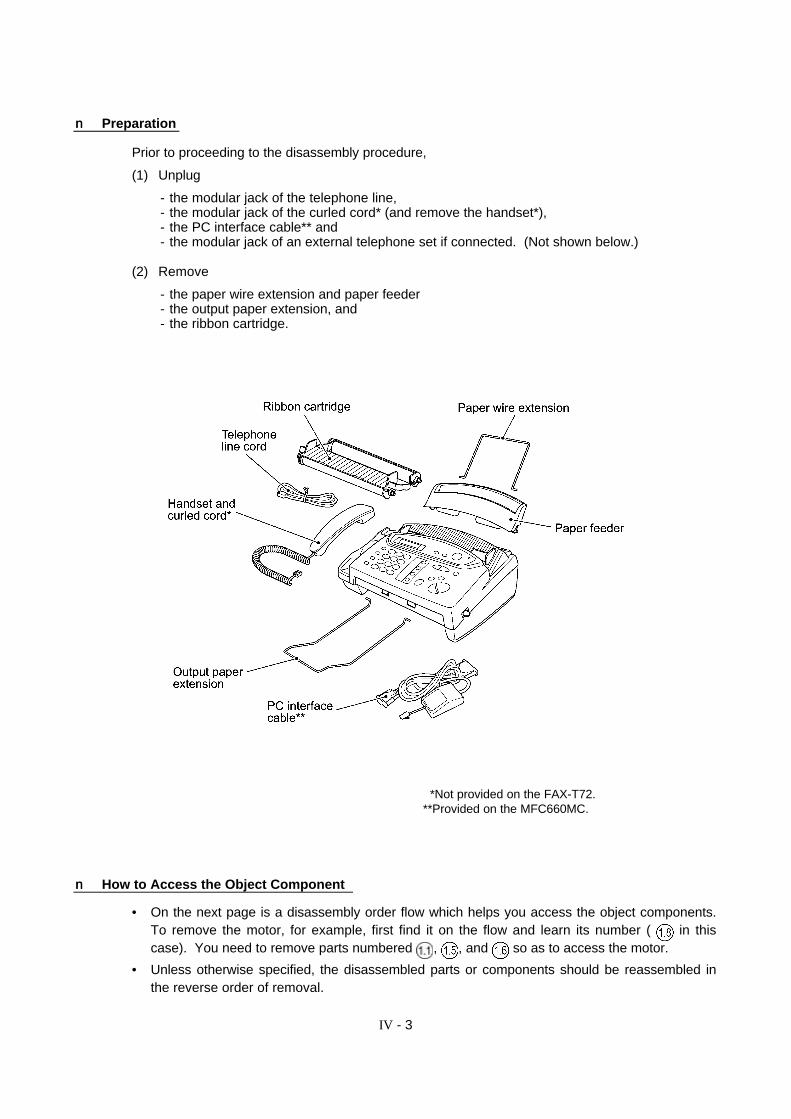
Prior to proceeding to the disassembly procedure,
(1) Unplug
- the modular jack of the telephone line,- the modular jack of the curled cord* (and remove the handset*),- the PC interface cable** and- the modular jack of an external telephone set if connected. (Not shown below.)
(2) Remove
- the paper wire extension and paper feeder- the output paper extension, and- the ribbon cartridge.
*Not provided on the FAX-T72.**Provided on the MFC660MC.
nn How to Access the Object Component
• On the next page is a disassembly order flow which helps you access the object components.To remove the motor, for example, first find it on the flow and learn its number ( in thiscase). You need to remove parts numbered , , and so as to access the motor.
• Unless otherwise specified, the disassembled parts or components should be reassembled inthe reverse order of removal.
IV - 4

IV - 5
1.1 Cover Stopper Link, Ribbon Shaft Stopper, ROM Cover, and Control Panel ASSY
(1) Open the control pane ASSY (in the direction of arrow Å).
(2) Remove the screw from the cover stopper link. Pull the link outwards (arrow Ç) to release itfrom the control panel ASSY and then turn it to the front (arrow É) to remove.
(3) Press the latch of the ribbon shaft stopper with a screwdriver to release it from the mainframe. The spring also comes off.
IV - 6
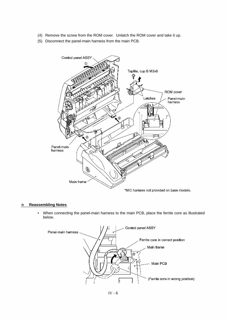
(4) Remove the screw from the ROM cover. Unlatch the ROM cover and take it up.
(5) Disconnect the panel-main harness from the main PCB.
nn Reassembling Notes
• When connecting the panel-main harness to the main PCB, place the ferrite core as illustratedbelow.
IV - 7
1.2 Disassembly of the Control Panel ASSY(Document pressure bar and chute cover ASSY)
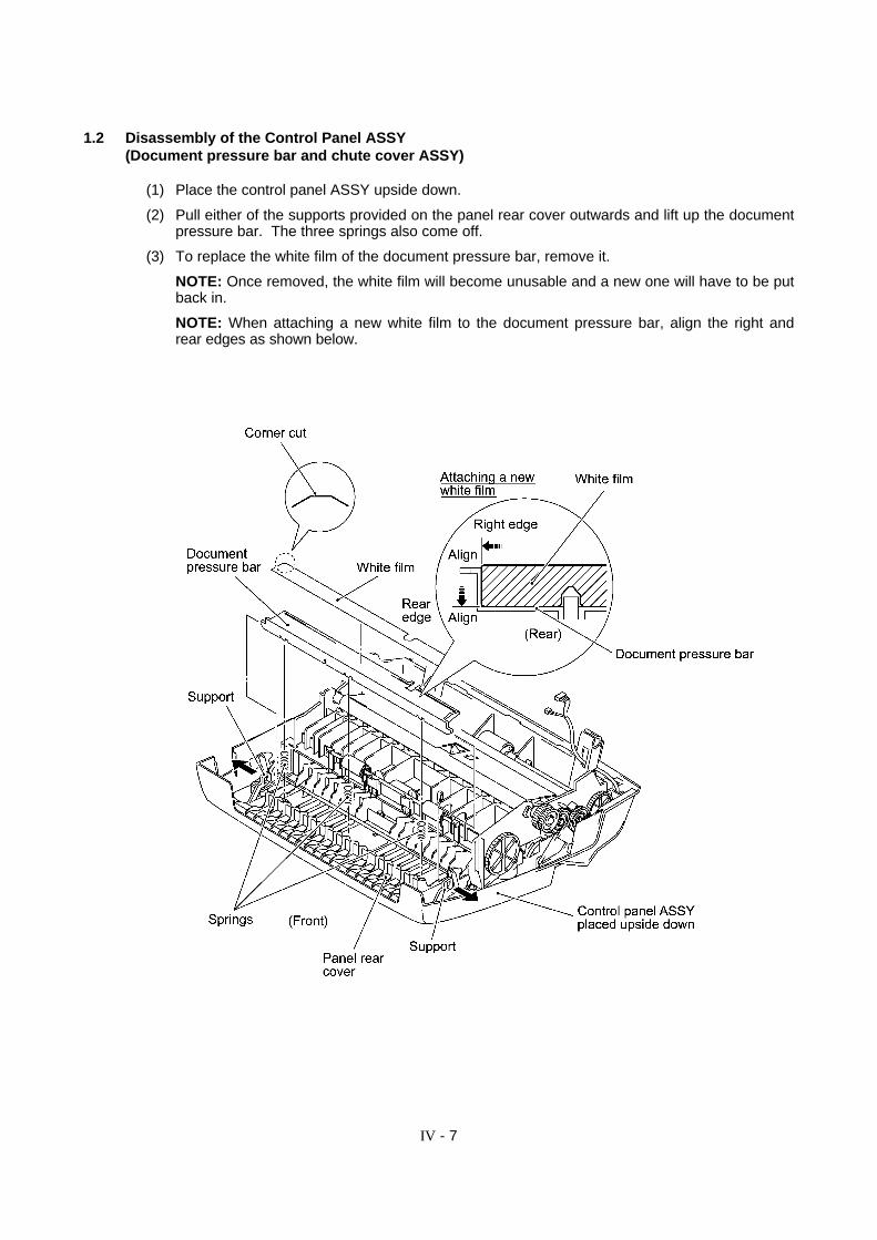
(1) Place the control panel ASSY upside down.
(2) Pull either of the supports provided on the panel rear cover outwards and lift up the documentpressure bar. The three springs also come off.
(3) To replace the white film of the document pressure bar, remove it.
NOTE: Once removed, the white film will become unusable and a new one will have to be putback in.
NOTE: When attaching a new white film to the document pressure bar, align the right andrear edges as shown below.
IV - 8
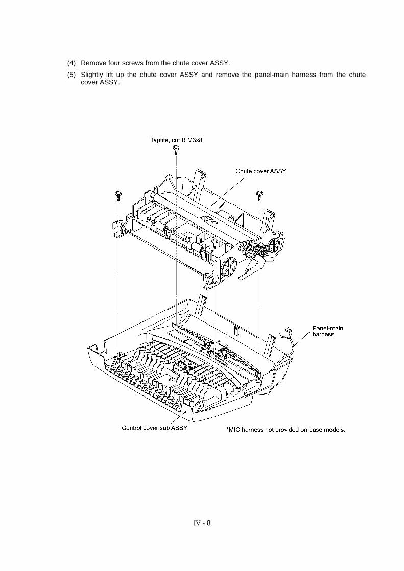
(4) Remove four screws from the chute cover ASSY.
(5) Slightly lift up the chute cover ASSY and remove the panel-main harness from the chutecover ASSY.

IV - 9
nn Reassembling Notes
• When reinstalling the chute cover ASSY, first pass the panel-main harness through the openingprovided in the chute cover ASSY and route it as shown below.
Then place the chute cover ASSY onto the control sub ASSY so that the box on the chutecover ASSY becomes fitted over the tab on the control cover sub ASSY.
Tighten four screws in the order shown below.

IV - 10
1.3 Disassembly of the Chute Cover ASSY(Paper pressure rollers, separation roller, paper feed roller 32, platen, registration sensoractuator, and lock bar & lock levers)
(1) Press the latches to release the pressure roller shaft and take out the paper pressure rollersand their shaft. The springs also come off.
(2) Press the locking arm and pull out the separation roller gear 46. Take out the separationroller.

IV - 11
(3) Press the locking arm and pull out the paper feed roller gear 37. Take out the paper feedroller 32.
IV - 12
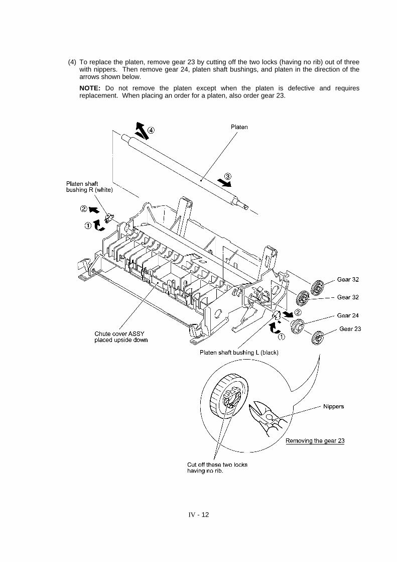
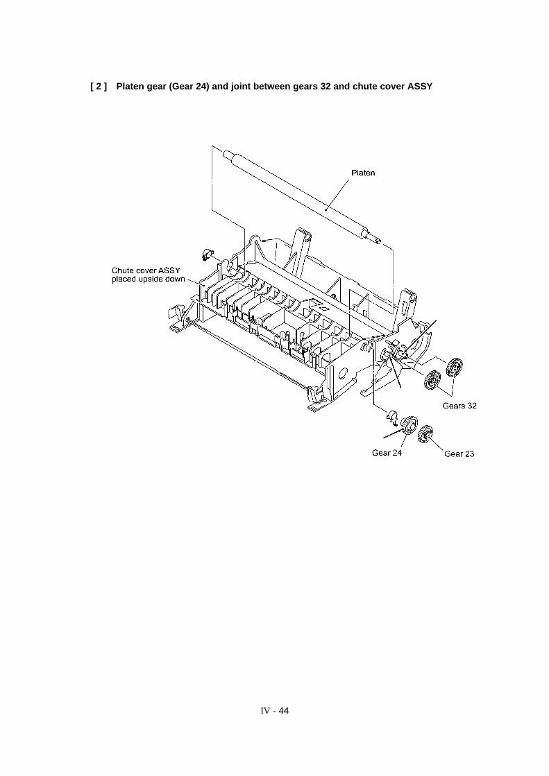
(4) To replace the platen, remove gear 23 by cutting off the two locks (having no rib) out of threewith nippers. Then remove gear 24, platen shaft bushings, and platen in the direction of thearrows shown below.
NOTE: Do not remove the platen except when the platen is defective and requiresreplacement. When placing an order for a platen, also order gear 23.
IV - 13
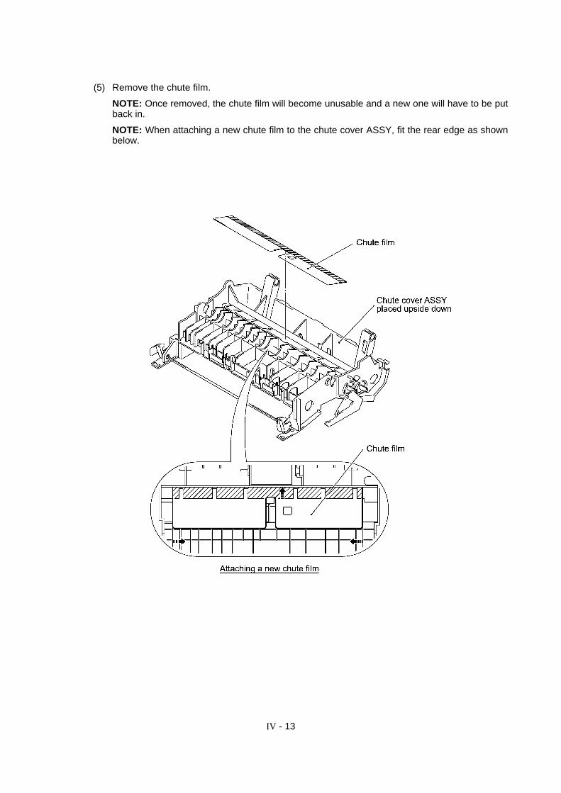
(5) Remove the chute film.
NOTE: Once removed, the chute film will become unusable and a new one will have to be putback in.
NOTE: When attaching a new chute film to the chute cover ASSY, fit the rear edge as shownbelow.
IV - 14
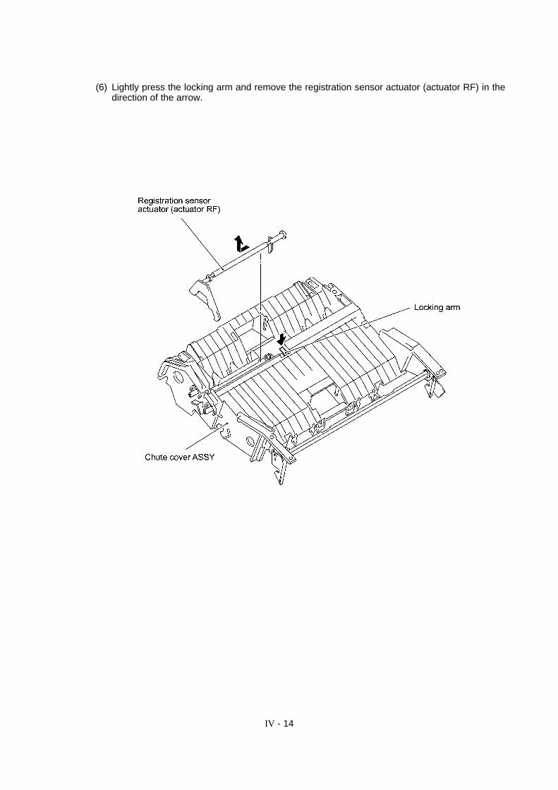
(6) Lightly press the locking arm and remove the registration sensor actuator (actuator RF) in thedirection of the arrow.
IV - 15
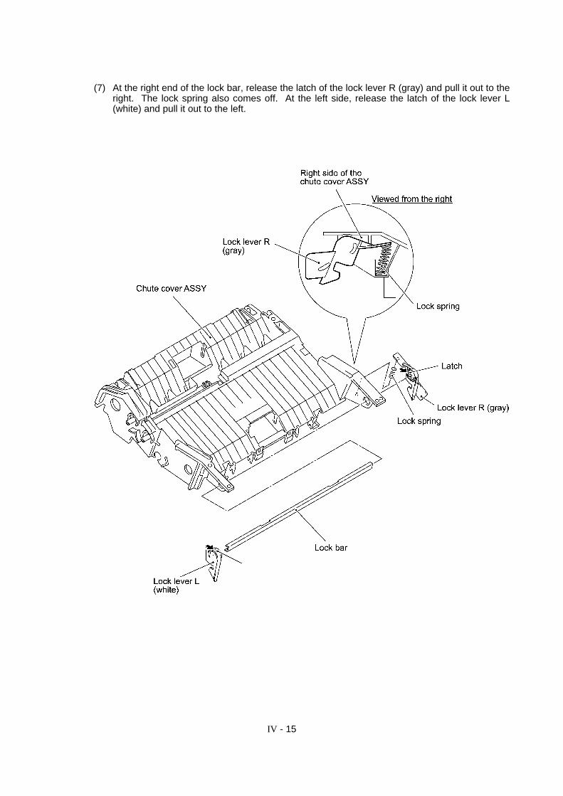
(7) At the right end of the lock bar, release the latch of the lock lever R (gray) and pull it out to theright. The lock spring also comes off. At the left side, release the latch of the lock lever L(white) and pull it out to the left.
IV - 16
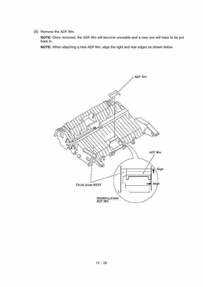
(8) Remove the ADF film.
NOTE: Once removed, the ADF film will become unusable and a new one will have to be putback in.
NOTE: When attaching a new ADF film, align the right and rear edges as shown below.

IV - 17
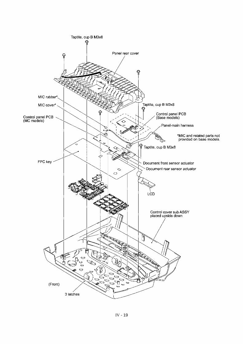
1.4 Disassembly of the Control Cover Sub ASSY(ACF parts, ADF parts, panel rear cover, control panel PCB, FPC key, LCD, and keys)
(1) Remove the two screws to release the ACF (auto cut sheet feeder) leaf spring.
(2) Remove two screws to release the ACF parts.
(3) Disassemble the ACF parts as illustrated below.

IV - 18
(4) Remove the screw and disassemble the ADF parts as illustrated below.
(5) Remove the four screws from the panel rear cover. (See the illustration given on the nextpage.)
(6) Unhook the panel rear cover from the three latches provided on the control cover sub ASSY,then slide the panel rear cover to the front to prevent it from catching the document front andrear sensor actuators.
(7) Remove the two screws (one screw on base models) from the control panel PCB and slide thecontrol panel PCB to the front. Slightly lift up the PCB, unlock the LCD flat cable connector,and disconnect the flat cable.
(8) Pull out the microphone (not provided on base models).
(9) Disconnect the panel-main harness from the control panel PCB.
(10) Disconnect the FPC key from the control panel PCB.
(11) As shown below, pull the locks outwards and gently pull out the LCD flat cable to take out theLCD.
IV - 19
IV - 20
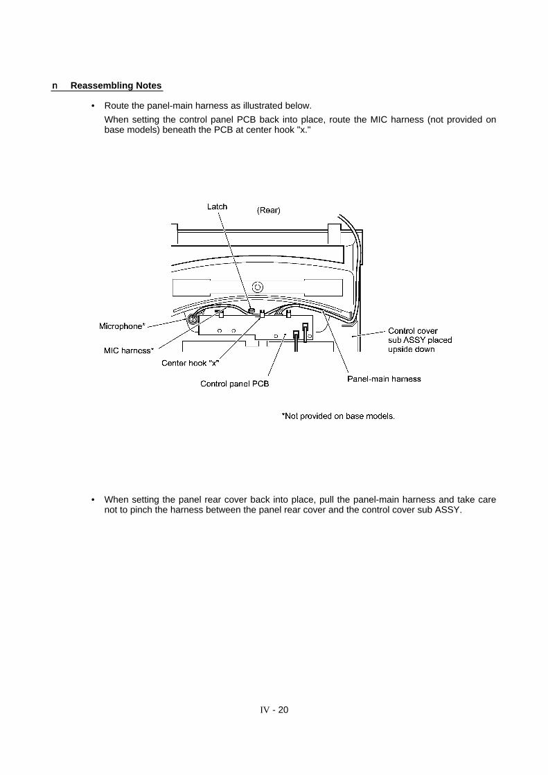
nn Reassembling Notes
• Route the panel-main harness as illustrated below.
When setting the control panel PCB back into place, route the MIC harness (not provided onbase models) beneath the PCB at center hook "x."
• When setting the panel rear cover back into place, pull the panel-main harness and take carenot to pinch the harness between the panel rear cover and the control cover sub ASSY.
IV - 21
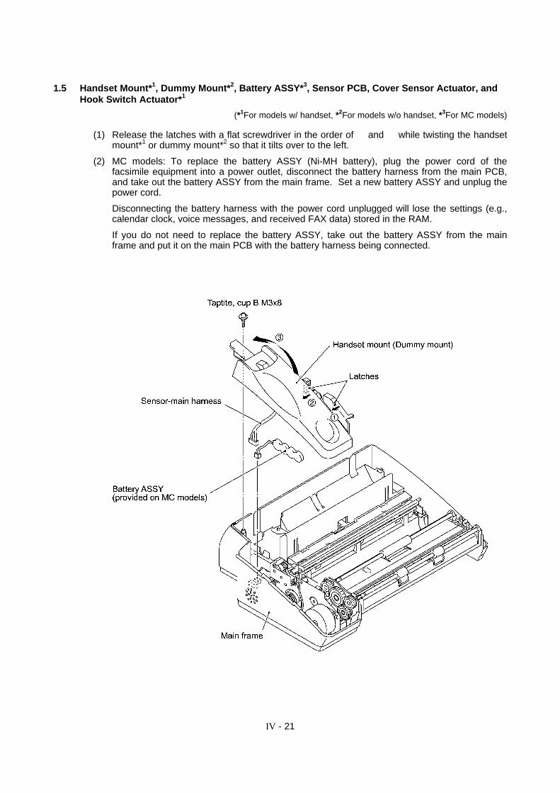
1.5 Handset Mount*1, Dummy Mount*2, Battery ASSY*3, Sensor PCB, Cover Sensor Actuator, andHook Switch Actuator*1
(*1For models w/ handset, *2For models w/o handset, *3For MC models)
(1) Release the latches with a flat screwdriver in the order of Å and Ç while twisting the handsetmount*1 or dummy mount*2 so that it tilts over to the left.
(2) MC models: To replace the battery ASSY (Ni-MH battery), plug the power cord of thefacsimile equipment into a power outlet, disconnect the battery harness from the main PCB,and take out the battery ASSY from the main frame. Set a new battery ASSY and unplug thepower cord.
Disconnecting the battery harness with the power cord unplugged will lose the settings (e.g.,calendar clock, voice messages, and received FAX data) stored in the RAM.
If you do not need to replace the battery ASSY, take out the battery ASSY from the mainframe and put it on the main PCB with the battery harness being connected.
IV - 22
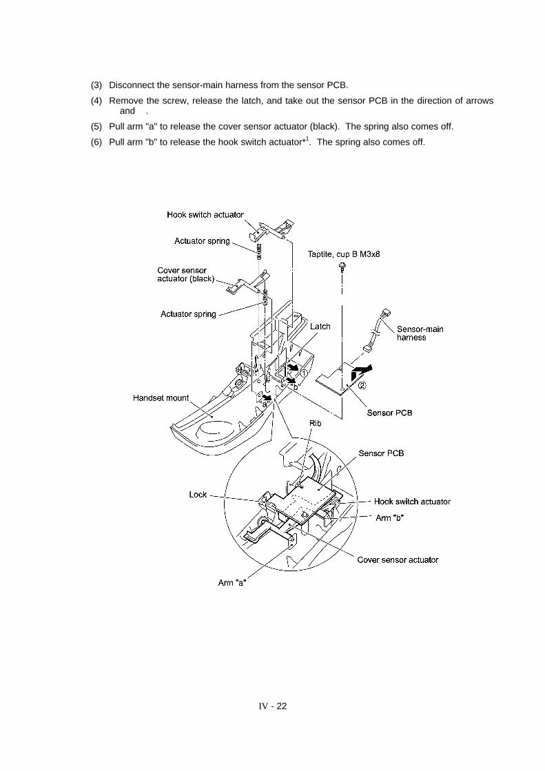
(3) Disconnect the sensor-main harness from the sensor PCB.
(4) Remove the screw, release the latch, and take out the sensor PCB in the direction of arrowsÅ and Ç.
(5) Pull arm "a" to release the cover sensor actuator (black). The spring also comes off.
(6) Pull arm "b" to release the hook switch actuator*1. The spring also comes off.

IV - 23
nn Reassembling Notes
• When setting the battery ASSY*3 back into place, route the battery harness as illustrated below.
• When setting the handset mount back into place, route the sensor-main harness around theboss as illustrated below.

IV - 24
1.6 Paper Ejection Roller, Document LF Roller, and Document Ejection Roller
(1) Unlatch the paper ejection roller and take it out.
(2) Remove the retaining ring and take the document LF roller out of the main frame.
(3) Remove the retaining ring and take the document ejection roller out of the main frame.

IV - 25
1.7 Head Protector, Recording Head ASSY, and Recorder Frame
(1) While pulling up the left end of the head protector, unhook latches Å through Ñ in this orderwith a small flat screwdriver as illustrated below.

IV - 26
(2) Push down both ends of the recording head ASSY and move it to the rear to release the tabsfrom the cutouts provided in the recorder frame.
(3) Disconnect the two harnesses (main-head harness and head-power harness) from therecording head ASSY and then lift up the ASSY.
(4) Remove the three head springs.

IV - 27
(5) Remove two screws to release the recorder frame.
(6) Remove the grounding spring.
(7) Unhook the head-power harness from the main frame.
nn Reassembling Notes
• Before reinstalling the recorder frame, check its top end (on which paper and ribbon pass) forscratches or burrs. Those on the top end will affect the printed image.
• When reinstalling the recording head ASSY, make sure that the three head springs are set intoplace.
IV - 28
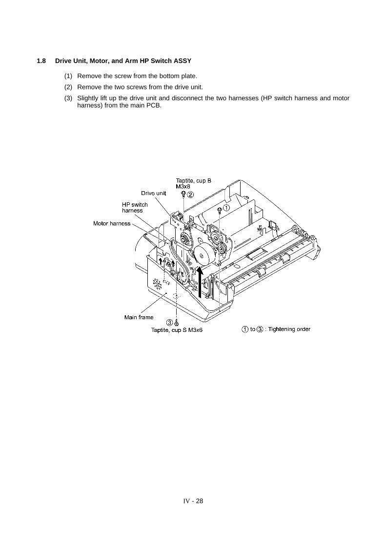
1.8 Drive Unit, Motor, and Arm HP Switch ASSY
(1) Remove the screw from the bottom plate.
(2) Remove the two screws from the drive unit.
(3) Slightly lift up the drive unit and disconnect the two harnesses (HP switch harness and motorharness) from the main PCB.
IV - 29
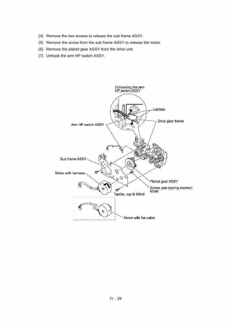
(4) Remove the two screws to release the sub frame ASSY.
(5) Remove the screw from the sub frame ASSY to release the motor.
(6) Remove the planet gear ASSY from the drive unit.
(7) Unhook the arm HP switch ASSY.
IV - 30
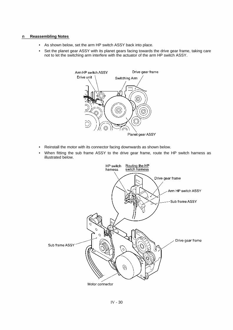
nn Reassembling Notes
• As shown below, set the arm HP switch ASSY back into place.
• Set the planet gear ASSY with its planet gears facing towards the drive gear frame, taking carenot to let the switching arm interfere with the actuator of the arm HP switch ASSY.
• Reinstall the motor with its connector facing downwards as shown below.
• When fitting the sub frame ASSY to the drive gear frame, route the HP switch harness asillustrated below.
IV - 31
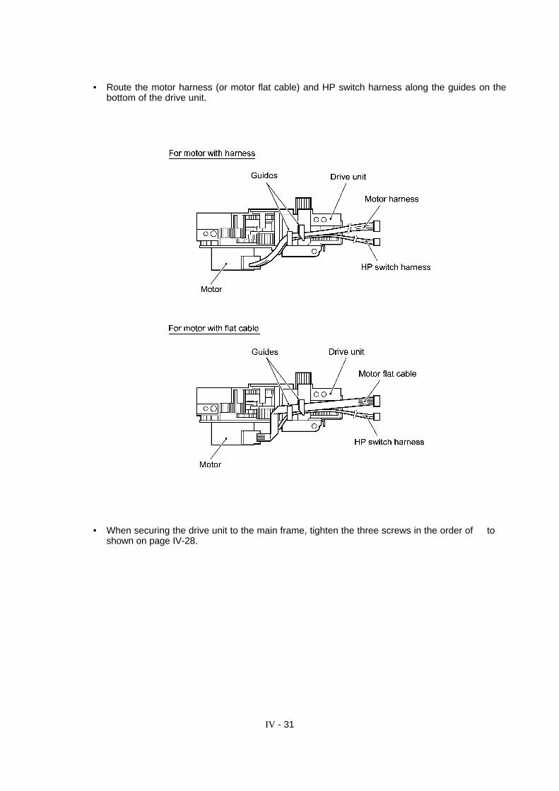
• Route the motor harness (or motor flat cable) and HP switch harness along the guides on thebottom of the drive unit.
• When securing the drive unit to the main frame, tighten the three screws in the order of Å to Éshown on page IV-28.

IV - 32
1.9 Speaker
(1) Disconnect the speaker harness from the main PCB.
(2) With a flat screwdriver, unhook the speaker support spring and pull it up.
(3) Remove the speaker.
IV - 33
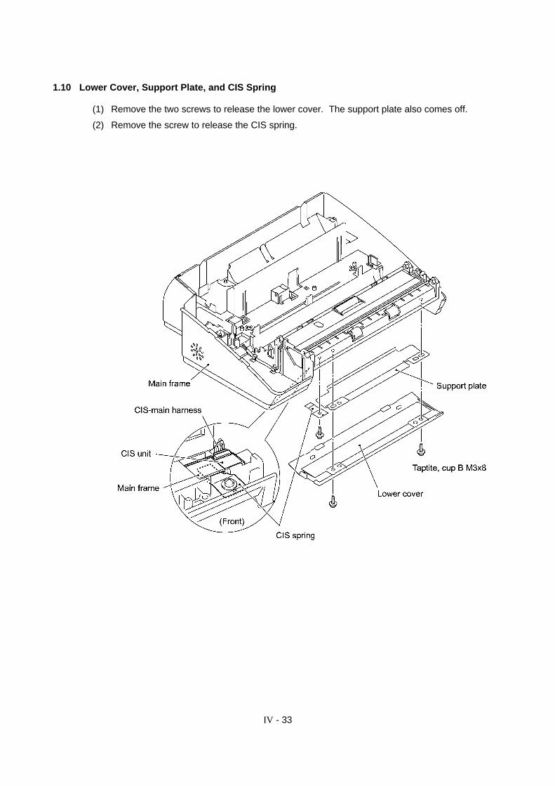
1.10 Lower Cover, Support Plate, and CIS Spring
(1) Remove the two screws to release the lower cover. The support plate also comes off.
(2) Remove the screw to release the CIS spring.
IV - 34
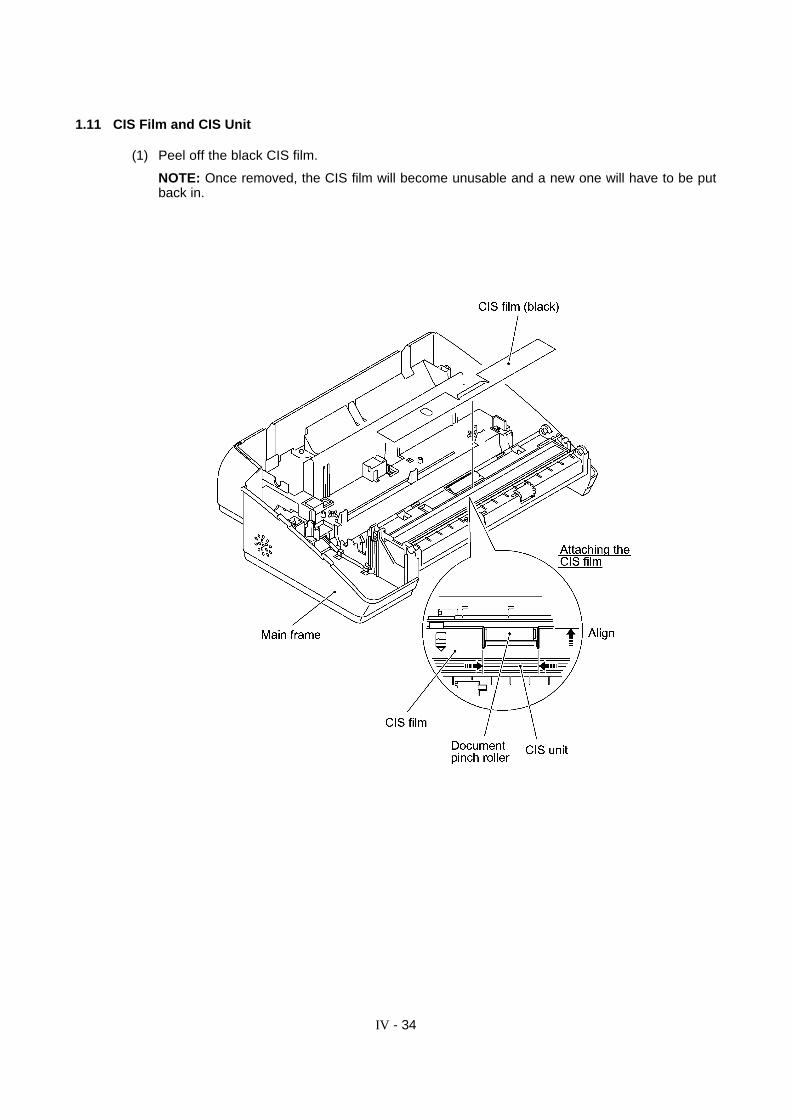
1.11 CIS Film and CIS Unit
(1) Peel off the black CIS film.
NOTE: Once removed, the CIS film will become unusable and a new one will have to be putback in.

IV - 35
(2) Remove screw "a" from the CIS holder.
(3) Push up the rear end of the CIS holder, slightly lift up the CIS unit, and disconnect the CIS-main harness from the CIS unit.
(4) Remove screw "b" to release the CIS holder.
IV - 36
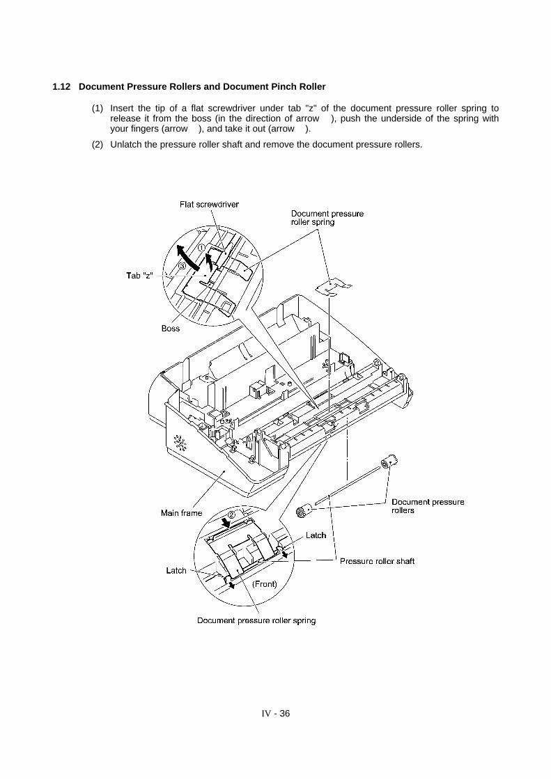
1.12 Document Pressure Rollers and Document Pinch Roller
(1) Insert the tip of a flat screwdriver under tab "z" of the document pressure roller spring torelease it from the boss (in the direction of arrow Å), push the underside of the spring withyour fingers (arrow Ç), and take it out (arrow É).
(2) Unlatch the pressure roller shaft and remove the document pressure rollers.
IV - 37
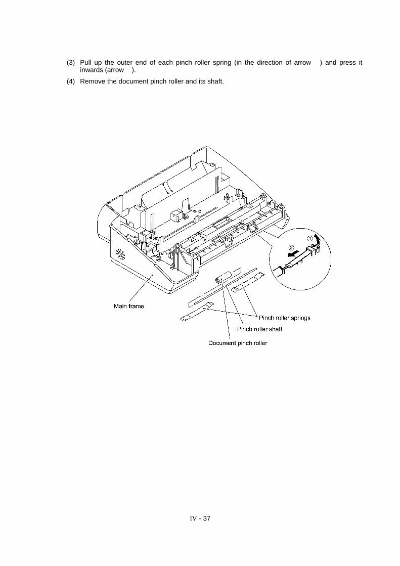
(3) Pull up the outer end of each pinch roller spring (in the direction of arrow Å) and press itinwards (arrow Ç).
(4) Remove the document pinch roller and its shaft.

IV - 38
1.13 Bottom Plate, Main PCB, NCU PCB, Power Supply PCB, and Ribbon Sensor Actuator
(1) Place the main frame upside down.
(2) Remove the five screws from the bottom plate.
(3) Slightly lift up the bottom plate and release the grounding wire.

IV - 39
(4) Remove the screw from the main PCB.
(5) Unhook the NCU PCB.
(6) Slightly lift up the main PCB, disconnect it from the NCU PCB, and disconnect the harnessesfrom the main PCB.
(7) Slightly lift up the NCU PCB and disconnect it from the power supply PCB.
(8) Slightly lift up the power supply PCB and disconnect the head-power harness.
IV - 40
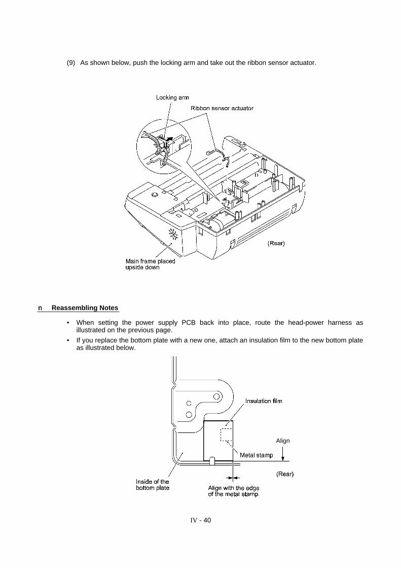
(9) As shown below, push the locking arm and take out the ribbon sensor actuator.
nn Reassembling Notes
• When setting the power supply PCB back into place, route the head-power harness asillustrated on the previous page.
• If you replace the bottom plate with a new one, attach an insulation film to the new bottom plateas illustrated below.
Align
IV - 41
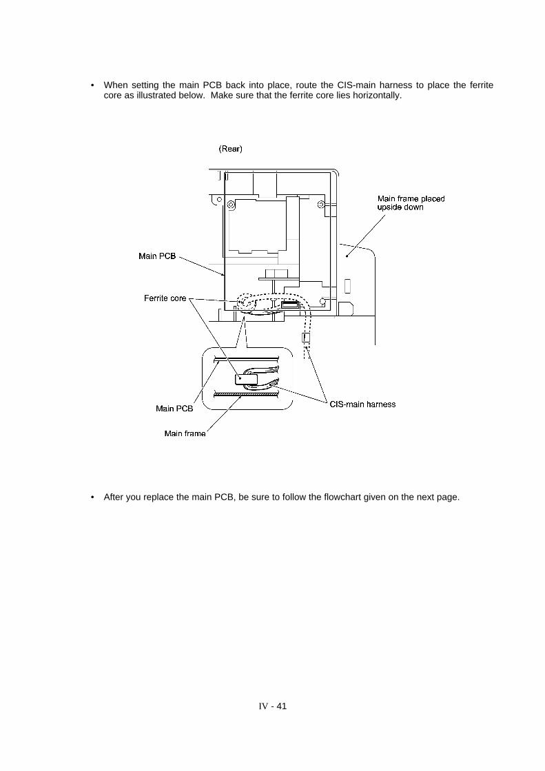
• When setting the main PCB back into place, route the CIS-main harness to place the ferritecore as illustrated below. Make sure that the ferrite core lies horizontally.
• After you replace the main PCB, be sure to follow the flowchart given on the next page.
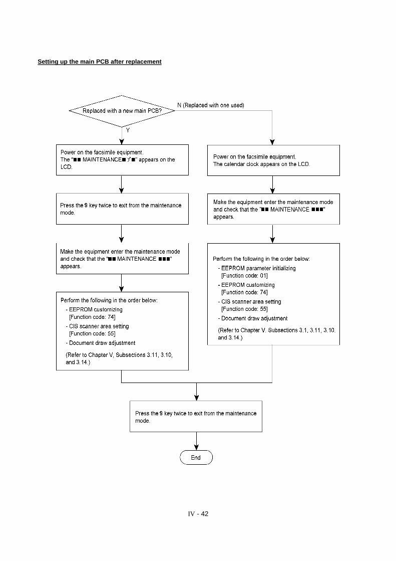
IV - 42
Setting up the main PCB after replacement

IV - 43
2. LUBRICATION
Apply the specified lubricants to the lubrication points as shown below.
Lubricant type (Manufacturer): Molykote EM-30L (Dow Corning) orFloil BG-11 (Kanto-Kasei Ltd.)
Apply a rice-sized pinch of grease (6 mm3) to the specified points.
[ 1 ] Separation roller and its gear and paper feed roller 32 and its gear
IV - 44
[ 2 ] Platen gear (Gear 24) and joint between gears 32 and chute cover ASSY

IV - 45
[ 3 ] Paper ejection roller, document LF roller, and document ejection roller

CHAPTER V.
MAINTENANCE MODE
CHAPTER V. MAINTENANCE MODE
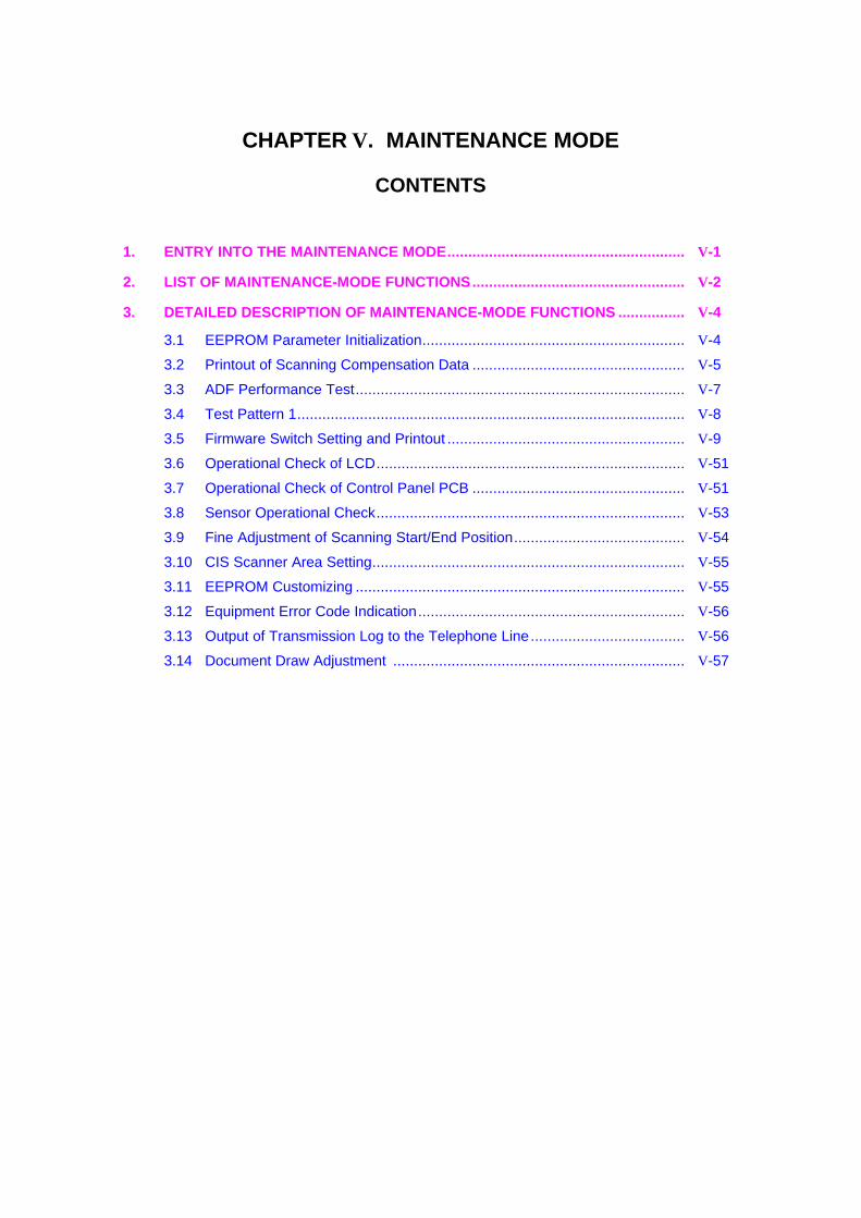
CONTENTS
1. ENTRY INTO THE MAINTENANCE MODE......................................................... V-1
2. LIST OF MAINTENANCE-MODE FUNCTIONS................................................... V-2
3. DETAILED DESCRIPTION OF MAINTENANCE-MODE FUNCTIONS ................ V-4
3.1 EEPROM Parameter Initialization............................................................... V-4
3.2 Printout of Scanning Compensation Data ................................................... V-5
3.3 ADF Performance Test............................................................................... V-7
3.4 Test Pattern 1............................................................................................. V-8
3.5 Firmware Switch Setting and Printout ......................................................... V-9
3.6 Operational Check of LCD.......................................................................... V-51
3.7 Operational Check of Control Panel PCB ................................................... V-51
3.8 Sensor Operational Check.......................................................................... V-53
3.9 Fine Adjustment of Scanning Start/End Position......................................... V-54
3.10 CIS Scanner Area Setting........................................................................... V-55
3.11 EEPROM Customizing ............................................................................... V-55
3.12 Equipment Error Code Indication................................................................ V-56
3.13 Output of Transmission Log to the Telephone Line..................................... V-56
3.14 Document Draw Adjustment ...................................................................... V-57

V - 1
1. ENTRY INTO THE MAINTENANCE MODE
American models (FAX560/FAX580MC/MFC660MC):
To make the facsimile equipment enter the maintenance mode, press the Function, *, 2, 8, 6, and 4 keys in this order. Within 2 seconds
European models (FAX-T72/FAX-T74/FAX-T76):
To make the facsimile equipment enter the maintenance mode, press the Menu, *, 2, 8, 6, and 4 keys in this order.
Within 2 seconds
The equipment beeps for approx. one second and displays " " on theLCD, indicating that it is placed in the initial stage of the maintenance mode, a mode in which theequipment is ready to accept entry from the keys.
To select one of the maintenance-mode functions listed in Section 2, enter the corresponding 2-digit function code with the numerical keys on the control panel. (The details of eachmaintenance-mode function are described in Section 3.)
NOTES: • Pressing the 9 key twice in the initial stage of the maintenance mode makes theequipment exit from the maintenance mode, restoring it to the standby state.
• Pressing the Stop button after entering only one digit restores the equipment to theinitial stage of the maintenance mode.
• If an invalid function code is entered, the equipment resumes the initial stage of themaintenance mode.
V - 2
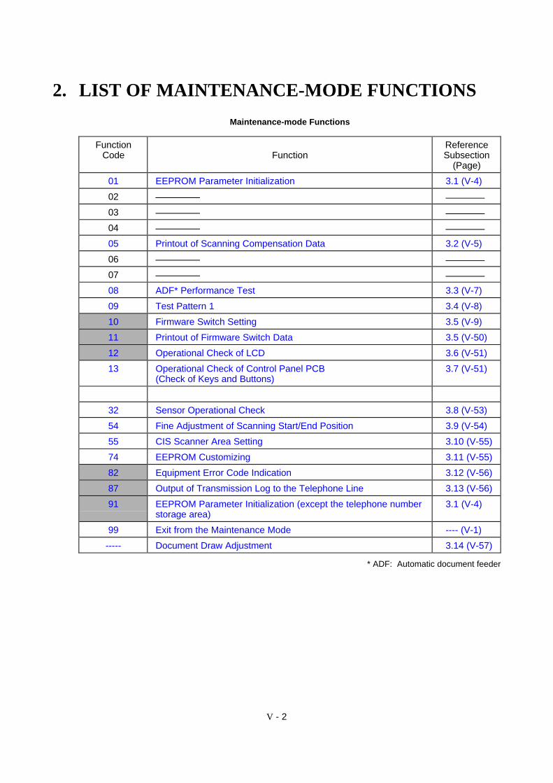
2. LIST OF MAINTENANCE-MODE FUNCTIONS
Maintenance-mode Functions
FunctionCode Function
ReferenceSubsection
(Page)
01 EEPROM Parameter Initialization 3.1 (V-4)
02
03
04
05 Printout of Scanning Compensation Data 3.2 (V-5)
06
07
08 ADF* Performance Test 3.3 (V-7)
09 Test Pattern 1 3.4 (V-8)
10 Firmware Switch Setting 3.5 (V-9)
11 Printout of Firmware Switch Data 3.5 (V-50)
12 Operational Check of LCD 3.6 (V-51)
13 Operational Check of Control Panel PCB(Check of Keys and Buttons)
3.7 (V-51)
32 Sensor Operational Check 3.8 (V-53)
54 Fine Adjustment of Scanning Start/End Position 3.9 (V-54)
55 CIS Scanner Area Setting 3.10 (V-55)
74 EEPROM Customizing 3.11 (V-55)
82 Equipment Error Code Indication 3.12 (V-56)
87 Output of Transmission Log to the Telephone Line 3.13 (V-56)
91 EEPROM Parameter Initialization (except the telephone numberstorage area)
3.1 (V-4)
99 Exit from the Maintenance Mode ---- (V-1)
----- Document Draw Adjustment 3.14 (V-57)
* ADF: Automatic document feeder
V - 3
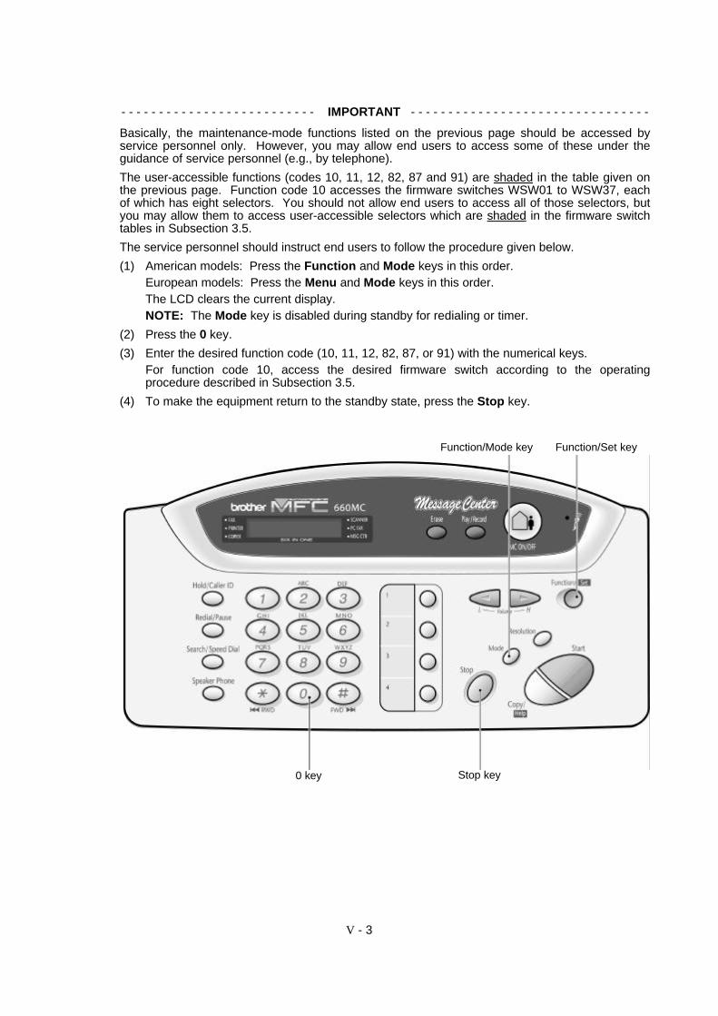
- - - - - - - - - - - - - - - - - - - - - - - - - - IMPORTANT - - - - - - - - - - - - - - - - - - - - - - - - - - - - - - - -
Basically, the maintenance-mode functions listed on the previous page should be accessed byservice personnel only. However, you may allow end users to access some of these under theguidance of service personnel (e.g., by telephone).
The user-accessible functions (codes 10, 11, 12, 82, 87 and 91) are shaded in the table given onthe previous page. Function code 10 accesses the firmware switches WSW01 to WSW37, eachof which has eight selectors. You should not allow end users to access all of those selectors, butyou may allow them to access user-accessible selectors which are shaded in the firmware switchtables in Subsection 3.5.
The service personnel should instruct end users to follow the procedure given below.
(1) American models: Press the Function and Mode keys in this order.European models: Press the Menu and Mode keys in this order.The LCD clears the current display.NOTE: The Mode key is disabled during standby for redialing or timer.
(2) Press the 0 key.
(3) Enter the desired function code (10, 11, 12, 82, 87, or 91) with the numerical keys.For function code 10, access the desired firmware switch according to the operatingprocedure described in Subsection 3.5.
(4) To make the equipment return to the standby state, press the Stop key.
Function/Mode key Function/Set key
Stop key0 key
V - 4
3. DETAILED DESCRIPTION OFMAINTENANCE-MODE FUNCTIONS
3.1 EEPROM Parameter Initialization
nn Function
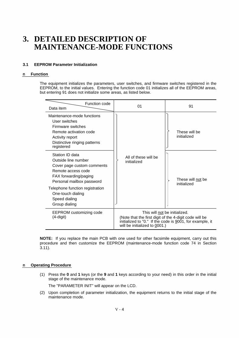
The equipment initializes the parameters, user switches, and firmware switches registered in theEEPROM, to the initial values. Entering the function code 01 initializes all of the EEPROM areas,but entering 91 does not initialize some areas, as listed below.
Function codeData item 01 91
Maintenance-mode functionsUser switchesFirmware switchesRemote activation codeActivity reportDistinctive ringing patternsregistered
These will beinitialized
Station ID dataOutside line numberCover page custom commentsRemote access codeFAX forwarding/pagingPersonal mailbox password
Telephone function registrationOne-touch dialingSpeed dialingGroup dialing
All of these will beinitialized
These will not beinitialized
EEPROM customizing code(4-digit)
This will not be initialized.(Note that the first digit of the 4-digit code will beinitialized to "0." If the code is 9001, for example, itwill be initialized to 0001.)
NOTE: If you replace the main PCB with one used for other facsimile equipment, carry out thisprocedure and then customize the EEPROM (maintenance-mode function code 74 in Section3.11).
nn Operating Procedure
(1) Press the 0 and 1 keys (or the 9 and 1 keys according to your need) in this order in the initialstage of the maintenance mode.
The "PARAMETER INIT" will appear on the LCD.
(2) Upon completion of parameter initialization, the equipment returns to the initial stage of themaintenance mode.

V - 5
3.2 Printout of Scanning Compensation Data
nn Function
The equipment prints out the white and black level data for scanning compensation.
nn Operating Procedure
Do not start this function merely after powering on the equipment but start it after carrying out asequence of scanning operation. Unless the equipment has carried out any scanning operation,this function cannot print out correct scanning compensation data. This is because at the start ofscanning operation, the equipment initializes white and black level data and takes in the scanningcompensation reference data.
(1) Press the 0 and 5 keys in this order in the initial stage of the maintenance mode.
The "WHITE LEVEL 1" will appear on the LCD.
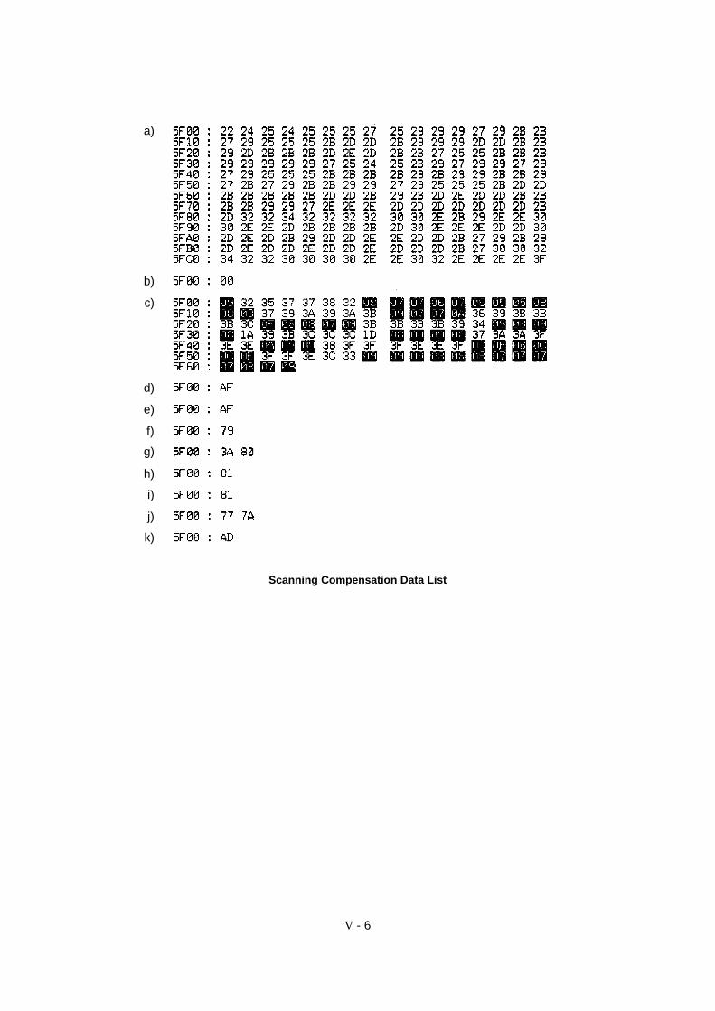
(2) The equipment prints out the scanning compensation data list containing the following:
a) White level data (208 bytes)b) Black level data (1 byte)c) White level data for compensation operation of background color (100 bytes)d) Initial clamp PWM value (1 byte)e) Clamp PWM value (1 byte)f) Compensation data for background color (1 byte)g) Upper and lower limit data for the compensation factor of background color (2 bytes)h) Initial LED light intensity value (1 byte)i) LED light intensity value (1 byte)j) LED light intensity value on the white film of the document pressure bar ASSY and
documents (2 bytes)k) Document rear sensor adjustment value (1 byte)
(3) Upon completion of recording of the compensation data list, the equipment returns to theinitial stage of the maintenance mode.
NOTE: If any data is abnormal, its code will be printed in inline style, as shown on the next page.
V - 6
Scanning Compensation Data List
a)
b)
c)
d)
e)
f)
g)
h)
i)
j)
k)

V - 7
3.3 ADF Performance Test
nn Function
The equipment counts the documents fed by the automatic document feeder (ADF) and displaysthe count on the LCD for checking the ADF performance.
nn Operating Procedure
(1) Set documents (Allowable up to the ADF capacity) in the initial stage of the maintenancemode.
The "DOC. READY" will appear on the LCD.
(2) Press the 0 and 8 keys in this order.
The equipment
i) copies the 1st document and displays “COPY P.01 STD” on the LCD.
ii) feeds in and out the 2nd through 4th documents while counting without copying them asthe LCD shows the corresponding count,
iii) copies the 5th document and displays “COPY P.05 STD” on the LCD,
iv) feeds in and out the 6th through 9th documents while counting without copying them asthe LCD shows the corresponding count, and
v) copies the 10th document and displays “COPY P.10 STD” on the LCD.
(3) Upon completion of feeding in and out all of the documents, the final count appears on theLCD.
(4) Press the Stop key to return the equipment to the initial maintenance mode.

V - 8
3.4 Test Pattern 1
nn Function
This function, much like the copying function, prints out test pattern 1 to allow the servicepersonnel to check for record data missing or print quality.
nn Operating Procedure
Press the 0 and 9 keys in this order in the initial stage of the maintenance mode.
The figure below shows test pattern 1.
Test Pattern 1

V - 9
3.5 Firmware Switch Setting and Printout
[ A ] Firmware switch setting
nn Function
The facsimile equipment incorporates the following firmware switch functions (WSW01 throughWSW37) which may be activated with the procedures using the control panel keys and buttons.The firmware switches have been set at the factory in conformity to the communications standardsand codes of each country. Do not disturb them unless necessary. Some firmware switches maynot be applicable in some versions. The firmware switch data list indicates "Not used." for thoseinapplicable switches.
Firmware Switches (WSW01 through WSW37)
WSW No. Function Reference PageWSW01 Dial pulse setting V-11WSW02 Tone signal setting V-12WSW03 PABX mode setting V-13WSW04 TRANSFER facility setting V-15WSW05 1st dial tone and busy tone detection V-16WSW06 Pause key setting and 2nd dial tone detection V-18WSW07 Dial tone setting 1 V-20WSW08 Dial tone setting 2 V-21WSW09 Protocol definition 1 V-22WSW10 Protocol definition 2 V-23WSW11 Busy tone setting V-24WSW12 Signal detection condition setting V-25WSW13 Modem setting V-26WSW14 AUTO ANS facility setting V-27WSW15 REDIAL facility setting V-28WSW16 Function setting 1 V-29WSW17 Function setting 2 V-30WSW18 Function setting 3 V-31WSW19 Transmission speed setting V-32WSW20 Overseas communications mode setting V-33WSW21 TAD setting 1 V-34WSW22 ECM and caller ID setting V-35WSW23 Communications setting V-36WSW24 TAD setting 2 V-37WSW25 TAD setting 3 V-38WSW26 Function setting 4 V-39WSW27 Function setting 5 V-40WSW28 Function setting 6 V-41WSW29 Function setting 7 V-42WSW30 Function setting 8 V-43WSW31 Function setting 9 V-44WSW32 Function setting 10 V-45WSW33 Function setting 11 V-46WSW34 Function setting 12 V-47WSW35 Function setting 13 V-48WSW36 Function setting 14 V-48WSW37 Function setting 15 V-49

V - 10
nn Operating Procedure
(1) Press the 1 and 0 keys in this order in the initial stage of the maintenance mode.
The equipment displays the "WSW00" on the LCD and becomes ready to accept a firmwareswitch number.
(2) Enter the desired number from the firmware switch numbers (01 through 37).
The following appears on the LCD:
WSWXX = 0 0 0 0 0 0 0 0
(3) Use the and keys to move the cursor to the selector position to be modified.
(4) Enter the desired number using the 0 and 1 keys.
(5) Press the Set key. This operation saves the newly entered selector values onto the EEPROMand readies the equipment for accepting a firmware switch number.
(6) Repeat steps (2) through (5) until the modification for the desired firmware switches iscompleted.
(7) Press the Set or Stop key to return the equipment to the initial stage of the maintenancemode.
NOTES: • To cancel this operation and return the equipment to the initial stage of themaintenance mode during the above procedure, press the Stop key.
• If there is a pause of more than one minute after a single-digit number is entered fordouble-digit firmware switch numbers, the equipment will automatically return to theinitial stage of the maintenance mode.
nn Note
The user-accessible selectors of the firmware switches are shaded in the tables given on thefollowing pages.
Selector No.1 Selector No.8
V - 11
nn Detailed Description for the Firmware Switches
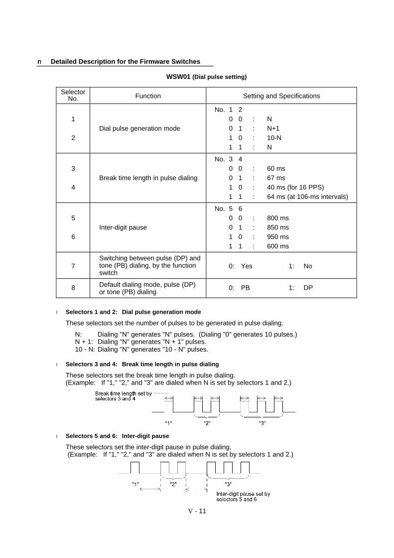
WSW01 (Dial pulse setting)
SelectorNo. Function Setting and Specifications
1
2Dial pulse generation mode
No. 1 20 0 : N0 1 : N+11 0 : 10-N1 1 : N
3
4Break time length in pulse dialing
No. 3 40 0 : 60 ms0 1 : 67 ms1 0 : 40 ms (for 16 PPS)1 1 : 64 ms (at 106-ms intervals)
5
6Inter-digit pause
No. 5 60 0 : 800 ms0 1 : 850 ms1 0 : 950 ms1 1 : 600 ms
7Switching between pulse (DP) andtone (PB) dialing, by the functionswitch
0: Yes 1: No
8 Default dialing mode, pulse (DP)or tone (PB) dialing
0: PB 1: DP
l Selectors 1 and 2: Dial pulse generation mode
These selectors set the number of pulses to be generated in pulse dialing.
N: Dialing "N" generates "N" pulses. (Dialing "0" generates 10 pulses.)N + 1: Dialing "N" generates "N + 1" pulses.10 - N: Dialing "N" generates "10 - N" pulses.
l Selectors 3 and 4: Break time length in pulse dialing
These selectors set the break time length in pulse dialing.(Example: If "1," "2," and "3" are dialed when N is set by selectors 1 and 2.)
l Selectors 5 and 6: Inter-digit pause
These selectors set the inter-digit pause in pulse dialing. (Example: If "1," "2," and "3" are dialed when N is set by selectors 1 and 2.)
V - 12
l Selector 7: Switching between pulse (DP) and tone (PB) dialing, by the function switch
This selector determines whether or not the dialing mode may be switched between the pulse (DP)and tone (PB) dialing by using the function switch.
l Selector 8: Default dialing mode, pulse (DP) or tone (PB) dialing
This selector sets the default dialing mode (pulse dialing or tone dialing) which may be changed bythe function switch. If the user switches it with the function switch when selector 7 is set to "0," thesetting specified by this selector will also be switched automatically.
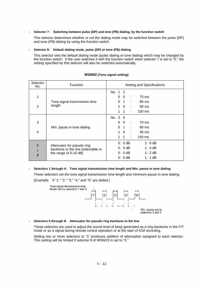
WSW02 (Tone signal setting)
SelectorNo. Function Setting and Specifications
1
2Tone signal transmission timelength
No. 1 20 0 : 70 ms0 1 : 80 ms1 0 : 90 ms1 1 : 100 ms
3
4Min. pause in tone dialing
No. 3 40 0 : 70 ms0 1 : 80 ms1 0 : 90 ms1 1 : 140 ms
5|8
Attenuator for pseudo ringbacktone to the line (selectable inthe range of 0-15 dB)
0: 0 dB 1: 8 dB0: 0 dB 1: 4 dB0: 0 dB 1: 2 dB0: 0 dB 1: 1 dB
l Selectors 1 through 4: Tone signal transmission time length and Min. pause in tone dialing
These selectors set the tone signal transmission time length and minimum pause in tone dialing.
(Example: If "1," "2," "3," "4," and "5" are dialed.)
l Selectors 5 through 8: Attenuator for pseudo ring backtone to the line
These selectors are used to adjust the sound level of beep generated as a ring backtone in the F/Tmode or as a signal during remote control operation or at the start of ICM recording.
Setting two or more selectors to “1” produces addition of attenuation assigned to each selector.This setting will be limited if selector 8 of WSW23 is set to “0.”

V - 13
WSW03 (PABX* mode setting)
SelectorNo. Function Setting and Specifications
1CNG detection when sharing amodular wall socket with atelephone
0: A 1: B
2|4
Min. detection time length ofPABX* dial tone, required forstarting dialing
No. 2 3 40 0 0 : 50 ms0 0 1 : 210 ms0 1 0 : 500 ms0 1 1 : 800 ms1 0 0 : 900 ms1 0 1 : 1.5 sec.1 1 0 : 2.0 sec.1 1 1 : 2.5 sec.
5CNG detection when sharing amodular wall socket with atelephone
0: A 1: B
6
7Dial tone detection in PABX*
No. 6 70 0 : No detection
(3.5 sec. WAIT)0 1 : No detection
(5 sec. WAIT)1 0 : No detection
(7 sec. WAIT)1 1 : Detection
(Frequency only)
8 “R” key function 0: 1st dial tone 1: No 1st dialdetection add tone detection
* PABX: Private automatic branch exchange
NOTE: Selectors 2 through 4 and 6 through 8 are not applicable where no PABX is installed.
l Selectors 1 and 5: CNG detection when sharing a modular wall socket with a telephone
These selectors determine whether or not the equipment detects a CNG signal when a line isconnected to a telephone sharing a modular wall socket with the equipment. Upon detection ofCNG signals by the number of cycles specified by these selectors, the equipment interprets CNGas an effective signal and then starts FAX reception.
SelectorNo. 1 No. 5
Cycle
0 (A) 0 (A)0 (A) 1 (B)1 (B) 0 (A)1 (B) 1 (B)
0.5 cycle1.0 cycle1.5 cycles2.0 cycles
l Selectors 2 through 4: Min. detection time length of PABX dial tone, required for starting dialing
Upon detection of the PABX dial tone for the time length set by these selectors, the equipmentstarts dialing.
These selectors are effective only when both selectors 6 and 7 are set to “1” (Detection).

V - 14
l Selectors 6 and 7: Dial tone detection in PABX
These selectors activate or deactivate the dial tone detection function which detects a dial tonewhen a line is connected to the PABX.
Setting both of these selectors to “1” activates the dial tone detection function so that theequipment starts dialing upon detection of a dial tone when a line is connected.
Other setting combinations deactivate the dial tone detection function so that the equipment startsdialing after the specified WAIT (3.5, 5.0, or 7.0 sec.) without detection of a dial tone when a line isconnected.
l Selector 8: “R” key function
This selector determines whether or not the 1st dial tone detection function (specified by selectors1 through 3 of WSW05) is added to the R key.
If this selector is set to “0,” pressing the R key automatically activates the 1st dial tone detectionfunction when the PABX and the automatic calling are selected by using the function switch. Ifyou press the R key and a dial number in succession, the equipment will automatically carry outthe 1st dial tone detection function following the original transfer function as shown below.
V - 15
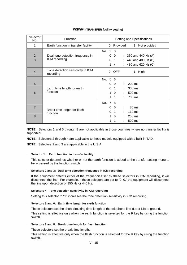
WSW04 (TRANSFER facility setting)
SelectorNo. Function Setting and Specifications
1 Earth function in transfer facility 0: Provided 1: Not provided
23
Dual tone detection frequency inICM recording
No. 2 30 0 : 350 and 440 Hz (A)0 1 : 440 and 480 Hz (B)1 x : 480 and 620 Hz (C)
4 Tone detection sensitivity in ICMrecording
0: OFF 1: High
5
6Earth time length for earthfunction
No. 5 60 0 : 200 ms0 1 : 300 ms1 0 : 500 ms1 1 : 700 ms
7
8
Break time length for flashfunction
No. 7 80 0 : 80 ms0 1 : 110 ms1 0 : 250 ms1 1 : 500 ms
NOTE: Selectors 1 and 5 through 8 are not applicable in those countries where no transfer facility issupported.
NOTE: Selectors 2 through 4 are applicable to those models equipped with a built-in TAD.
NOTE: Selectors 2 and 3 are applicable in the U.S.A.
l Selector 1: Earth function in transfer facility
This selector determines whether or not the earth function is added to the transfer setting menu tobe accessed by the function switch.
l Selectors 2 and 3: Dual tone detection frequency in ICM recording
If the equipment detects either of the frequencies set by these selectors in ICM recording, it willdisconnect the line. For example, if these selectors are set to “0, 0,” the equipment will disconnectthe line upon detection of 350 Hz or 440 Hz.
l Selectors 4: Tone detection sensitivity in ICM recording
Setting this selector to “1” increases the tone detection sensitivity in ICM recording.
l Selectors 5 and 6: Earth time length for earth function
These selectors set the short-circuiting time length of the telephone line (La or Lb) to ground.
This setting is effective only when the earth function is selected for the R key by using the functionswitch.
l Selectors 7 and 8: Break time length for flash function
These selectors set the break time length.
This setting is effective only when the flash function is selected for the R key by using the functionswitch.
V - 16
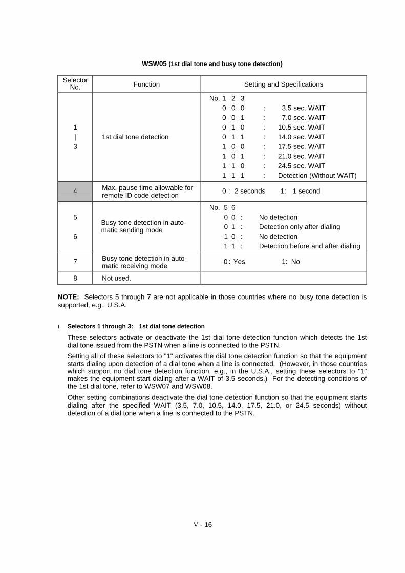
WSW05 (1st dial tone and busy tone detection)
SelectorNo. Function Setting and Specifications
1|3
1st dial tone detection
No. 1 2 30 0 0 : 3.5 sec. WAIT0 0 1 : 7.0 sec. WAIT0 1 0 : 10.5 sec. WAIT0 1 1 : 14.0 sec. WAIT1 0 0 : 17.5 sec. WAIT1 0 1 : 21.0 sec. WAIT1 1 0 : 24.5 sec. WAIT1 1 1 : Detection (Without WAIT)
4 Max. pause time allowable forremote ID code detection
0 : 2 seconds 1: 1 second
5
6
Busy tone detection in auto-matic sending mode
No. 5 60 0 : No detection0 1 : Detection only after dialing1 0 : No detection1 1 : Detection before and after dialing
7 Busy tone detection in auto-matic receiving mode
0 : Yes 1: No
8 Not used.
NOTE: Selectors 5 through 7 are not applicable in those countries where no busy tone detection issupported, e.g., U.S.A.
ll Selectors 1 through 3: 1st dial tone detection
These selectors activate or deactivate the 1st dial tone detection function which detects the 1stdial tone issued from the PSTN when a line is connected to the PSTN.
Setting all of these selectors to "1" activates the dial tone detection function so that the equipmentstarts dialing upon detection of a dial tone when a line is connected. (However, in those countrieswhich support no dial tone detection function, e.g., in the U.S.A., setting these selectors to "1"makes the equipment start dialing after a WAIT of 3.5 seconds.) For the detecting conditions ofthe 1st dial tone, refer to WSW07 and WSW08.
Other setting combinations deactivate the dial tone detection function so that the equipment startsdialing after the specified WAIT (3.5, 7.0, 10.5, 14.0, 17.5, 21.0, or 24.5 seconds) withoutdetection of a dial tone when a line is connected to the PSTN.

V - 17
l Selector 4: Max. pause time allowable for remote ID code detection
This selector sets the maximum pause time allowable for detecting the second digit of a remote IDcode after detection of the first digit in remote reception.
If selector 4 is set to "0" (2 seconds), for instance, only a remote ID code whose second digit isdetected within 2 seconds after detection of the first digit will become effective so as to activatethe remote function.
l Selectors 5 and 6: Busy tone detection in automatic sending mode
These selectors determine whether or not the equipment automatically disconnects a line upondetection of a busy tone in automatic sending mode.
Setting selector 6 to "0" ignores a busy tone so that the equipment does not disconnect the line.
Setting selectors 5 and 6 to "0" and "1," respectively, makes the equipment detect a busy toneonly after dialing and disconnect the line.
Setting both of selectors 5 and 6 to "1" makes the equipment detect a busy tone before and afterdialing and then disconnect the line.
l Selector 7: Busy tone detection in automatic receiving mode
This selector determines whether or not the equipment automatically disconnects a line upondetection of a busy tone in automatic receiving mode.
V - 18
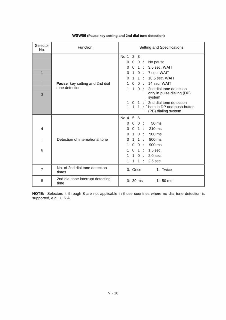
WSW06 (Pause key setting and 2nd dial tone detection)
SelectorNo.
Function Setting and Specifications
1
|
3
Pause key setting and 2nd dialtone detection
No.1 2 30 0 0 : No pause0 0 1 : 3.5 sec. WAIT0 1 0 : 7 sec. WAIT0 1 1 : 10.5 sec. WAIT1 0 0 : 14 sec. WAIT1 1 0 : 2nd dial tone detection
only in pulse dialing (DP)system
1 0 1 : 2nd dial tone detection1 1 1 : both in DP and push-button
(PB) dialing system
4
|
6
Detection of international tone
No.4 5 60 0 0 : 50 ms0 0 1 : 210 ms0 1 0 : 500 ms0 1 1 : 800 ms1 0 0 : 900 ms1 0 1 : 1.5 sec.1 1 0 : 2.0 sec.1 1 1 : 2.5 sec.
7 No. of 2nd dial tone detectiontimes
0: Once 1: Twice
8 2nd dial tone interrupt detectingtime
0: 30 ms 1: 50 ms
NOTE: Selectors 4 through 8 are not applicable in those countries where no dial tone detection issupported, e.g., U.S.A.

V - 19
l Selectors 1 through 3: Pause key setting and 2nd dial tone detection
Selectors1 2 3
0 0 0 No WAIT is inserted even if the Pause key is pressed.
0 0 10 1 00 1 11 0 0
If you press the Pause key during dialing, the facsimile equipment willinsert WAIT as defined in the above table.If the Pause key is pressed repeatedly, the equipment inserts thespecified WAIT multiplied by the number of depressions. It applies alsoin hook-up dialing.
1 0 11 1 01 1 1
When these selectors are set to "1, 0, 1":Each time you press the Pause key in dialing, the equipment will wait forthe 2nd dial tone to be sent via the communications line regardless ofpulse dialing or tone dialing.
When these selectors are set to "1, 1, 0":If you press the Pause key in pulse dialing, the equipment will first waitfor the 2nd dial tone to be sent via the communications line. After that,pressing the Pause key will cause the equipment to insert a WAIT of 3.5seconds. In tone dialing, the equipment will insert a WAIT of 3.5seconds.
When these selectors are set to "1, 1, 1":If you press the Pause key, the equipment will first wait for the 2nd dialtone to be sent via the communications line regardless of pulse dialing ortone dialing. After that, pressing the Pause key will cause the equipmentto insert a WAIT of 3.5 seconds.
(In those countries where no dial tone detection function is supported,setting these selectors to "1, 1, 0," "1, 0, 1," or "1, 1, 1" inserts a WAIT of3.5 seconds.)
l Selectors 4 through 6: Detection of international tone
Upon detection of the 2nd dial tone for the time length specified by these selectors, the equipmentstarts dialing.
This setting is effective only when the 2nd dial tone detection function is activated by selectors 1through 3 (Setting 1 0 1, 1 1 0, or 1 1 1).
This function does not apply in those countries where no dial tone detection function is supported.
l Selector 7: No. of 2nd dial tone detection times
This selector sets the number of dial tone detection times required for starting dialing.
l Selector 8: 2nd dial tone interrupt detecting time
This selector sets the allowable time length of an interrupt which should not be interpreted as aninterrupt in the 2nd tone dialing.
V - 20
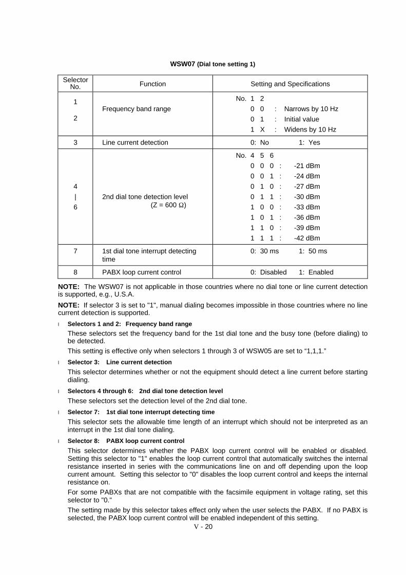
WSW07 (Dial tone setting 1)
SelectorNo. Function Setting and Specifications
1
2Frequency band range
No. 1 2
0 0 : Narrows by 10 Hz
0 1 : Initial value
1 X : Widens by 10 Hz
3 Line current detection 0: No 1: Yes
4
|
6
2nd dial tone detection level(Z = 600 Ω)
No. 4 5 6
0 0 0 : -21 dBm
0 0 1 : -24 dBm
0 1 0 : -27 dBm
0 1 1 : -30 dBm
1 0 0 : -33 dBm
1 0 1 : -36 dBm
1 1 0 : -39 dBm
1 1 1 : -42 dBm
7 1st dial tone interrupt detectingtime
0: 30 ms 1: 50 ms
8 PABX loop current control 0: Disabled 1: Enabled
NOTE: The WSW07 is not applicable in those countries where no dial tone or line current detectionis supported, e.g., U.S.A.
NOTE: If selector 3 is set to "1", manual dialing becomes impossible in those countries where no linecurrent detection is supported.
l Selectors 1 and 2: Frequency band range
These selectors set the frequency band for the 1st dial tone and the busy tone (before dialing) tobe detected.
This setting is effective only when selectors 1 through 3 of WSW05 are set to “1,1,1.”
l Selector 3: Line current detection
This selector determines whether or not the equipment should detect a line current before startingdialing.
l Selectors 4 through 6: 2nd dial tone detection level
These selectors set the detection level of the 2nd dial tone.
l Selector 7: 1st dial tone interrupt detecting time
This selector sets the allowable time length of an interrupt which should not be interpreted as aninterrupt in the 1st dial tone dialing.
l Selector 8: PABX loop current control
This selector determines whether the PABX loop current control will be enabled or disabled.Setting this selector to "1" enables the loop current control that automatically switches the internalresistance inserted in series with the communications line on and off depending upon the loopcurrent amount. Setting this selector to "0" disables the loop current control and keeps the internalresistance on.
For some PABXs that are not compatible with the facsimile equipment in voltage rating, set thisselector to "0."
The setting made by this selector takes effect only when the user selects the PABX. If no PABX isselected, the PABX loop current control will be enabled independent of this setting.

V - 21
WSW08 (Dial tone setting 2)
SelectorNo. Function Setting and Specifications
1
|
3
1st dial tone detection timelength
No. 1 2 30 0 0 : 50 ms0 0 1 : 210 ms0 1 0 : 500 ms0 1 1 : 800 ms1 0 0 : 900 ms1 0 1 : 1.5 sec.1 1 0 : 2.0 sec.1 1 1 : 2.5 sec.
4
5
Time-out length for 1st and 2nddial tone detection
No. 4 50 0 : 10 sec.
0 1 : 20 sec.
1 0 : 15 sec.
1 1 : 30 sec.
6
|
8
Detection level of 1st dial toneand busy tone before dialing
No. 6 7 8
0 0 0 : -21 dBm
0 0 1 : -24 dBm
0 1 0 : -27 dBm
0 1 1 : -30 dBm
1 0 0 : -33 dBm
1 0 1 : -36 dBm
1 1 0 : -39 dBm
1 1 1 : -42 dBm
NOTE: The WSW08 is not applicable in those countries where no dial tone detection is supported,e.g., U.S.A.
l Selectors 1 through 3: 1st dial tone detection time length
Upon detection of the 1st dial tone for the time length set by these selectors, the equipment startsdialing.
This setting is effective only when selectors 1 through 3 of WSW05 are set to "1,1,1."
l Selectors 4 and 5: Time-out length for 1st and 2nd dial tone detection
These selectors set the time-out length for the 1st and 2nd dial tone detection so that theequipment waits dial tone input for the specified time length and disconnects itself from the linewhen no dial tone is inputted.
V - 22
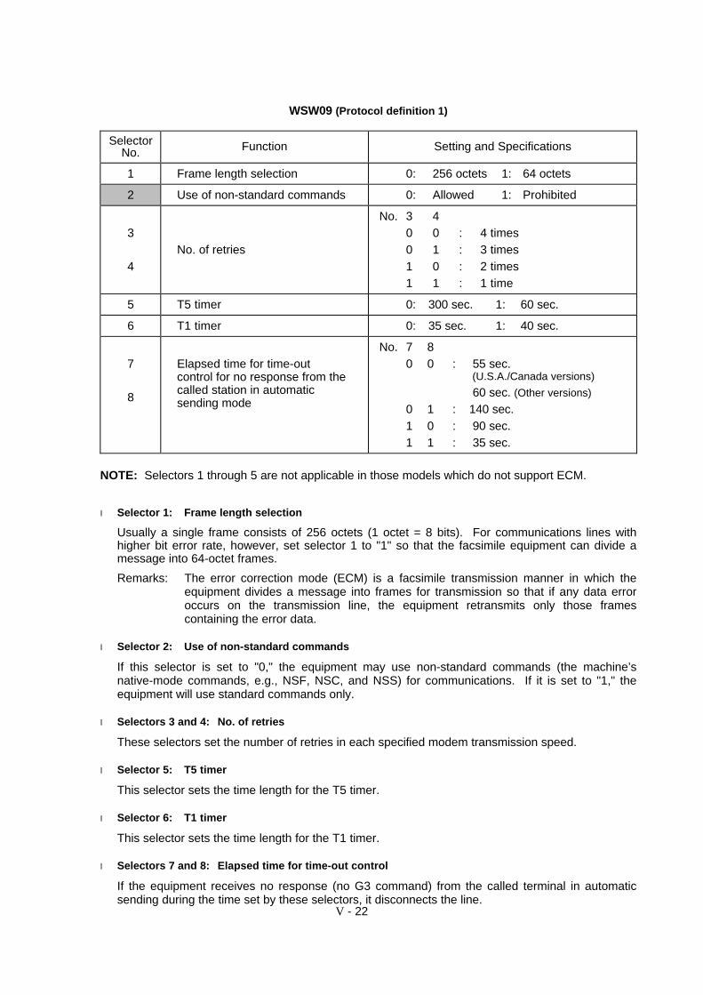
WSW09 (Protocol definition 1)
SelectorNo. Function Setting and Specifications
1 Frame length selection 0: 256 octets 1: 64 octets
2 Use of non-standard commands 0: Allowed 1: Prohibited
3
4No. of retries
No. 3 40 0 : 4 times0 1 : 3 times1 0 : 2 times1 1 : 1 time
5 T5 timer 0: 300 sec. 1: 60 sec.
6 T1 timer 0: 35 sec. 1: 40 sec.
7
8
Elapsed time for time-outcontrol for no response from thecalled station in automaticsending mode
No. 7 80 0 : 55 sec.
(U.S.A./Canada versions)
60 sec. (Other versions)
0 1 : 140 sec.1 0 : 90 sec.1 1 : 35 sec.
NOTE: Selectors 1 through 5 are not applicable in those models which do not support ECM.
l Selector 1: Frame length selection
Usually a single frame consists of 256 octets (1 octet = 8 bits). For communications lines withhigher bit error rate, however, set selector 1 to "1" so that the facsimile equipment can divide amessage into 64-octet frames.
Remarks: The error correction mode (ECM) is a facsimile transmission manner in which theequipment divides a message into frames for transmission so that if any data erroroccurs on the transmission line, the equipment retransmits only those framescontaining the error data.
l Selector 2: Use of non-standard commands
If this selector is set to "0," the equipment may use non-standard commands (the machine’snative-mode commands, e.g., NSF, NSC, and NSS) for communications. If it is set to "1," theequipment will use standard commands only.
l Selectors 3 and 4: No. of retries
These selectors set the number of retries in each specified modem transmission speed.
l Selector 5: T5 timer
This selector sets the time length for the T5 timer.
l Selector 6: T1 timer
This selector sets the time length for the T1 timer.
l Selectors 7 and 8: Elapsed time for time-out control
If the equipment receives no response (no G3 command) from the called terminal in automaticsending during the time set by these selectors, it disconnects the line.

V - 23
WSW10 (Protocol definition 2)
SelectorNo. Function Setting and Specifications
1 Switching of DPS, following theCML ON/OFF
0: No 1: Yes
2 Time length from transmission ofthe last dial digit to CML ON
0: 100 ms 1: 50 ms
3 Time length from CML ON to CNGtransmission
0: 2 sec. 1: 4 sec.
4Time length from CML ON to CEDtransmission (except for facsimile-to-telephone switching)
0: 0.5 sec. 1: 2 sec.
5
6No. of training retries
No. 5 60 0 : 1 time0 1 : 2 times1 0 : 3 times1 1 : 4 times
78
Not used.
l Selector 1: Switching of DPS, following the CML ON/OFF
Setting this selector to "1" automatically switches DPS following the CML ON/OFF operation.
l Selector 2: Time length from transmission of the last dial digit to CML ON
This selector sets the time length from when the equipment transmits the last dial digit until theCML relay comes on.
l Selector 3: Time length from CML ON to CNG transmission
This selector sets the time length until the equipment transmits a CNG after it turns on the CMLrelay.
l Selector 4: Time length from CML ON to CED transmission
This selector sets the time length until the equipment transmits a CED after it turns on the CMLrelay. This setting does not apply to switching between facsimile and telephone.
l Selectors 5 and 6: No. of training retries
These selectors set the number of training retries to be repeated before automatic fallback.
V - 24
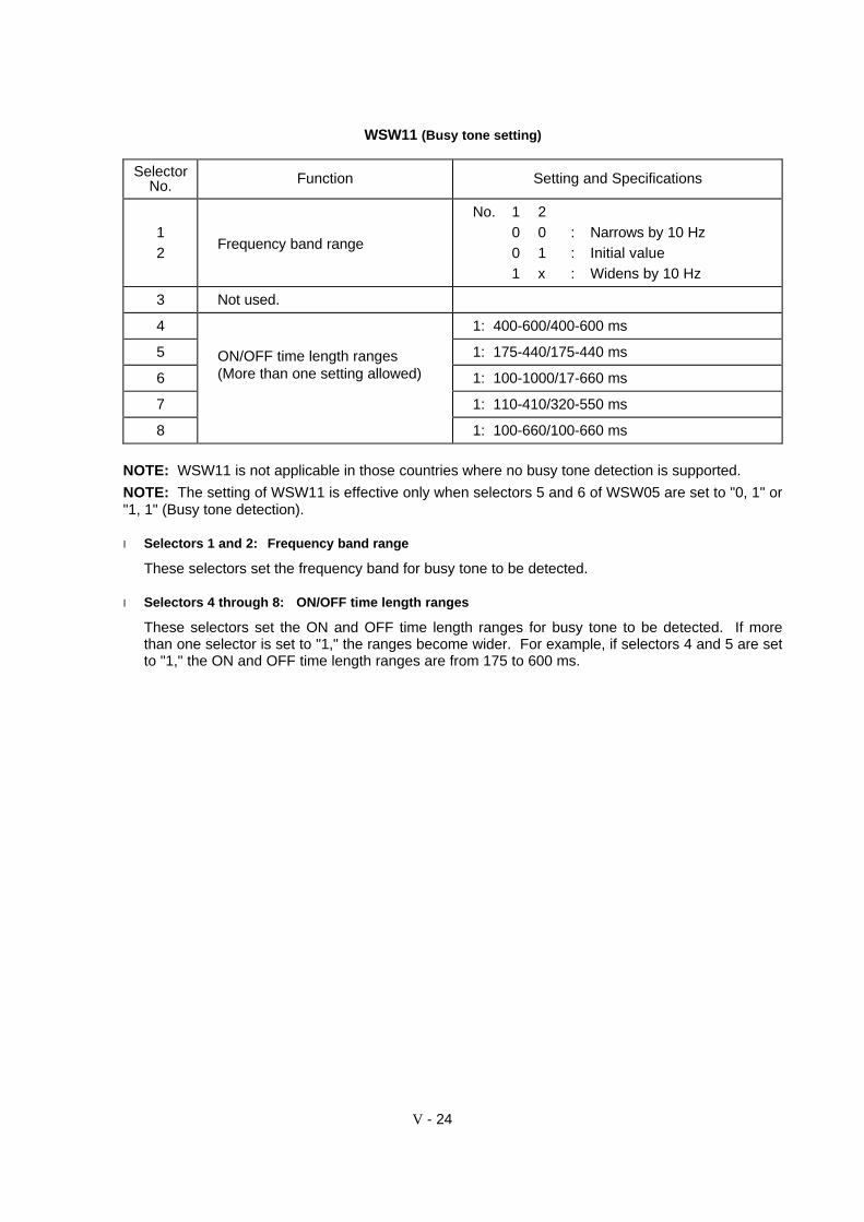
WSW11 (Busy tone setting)
SelectorNo. Function Setting and Specifications
12
Frequency band range
No. 1 20 0 : Narrows by 10 Hz0 1 : Initial value1 x : Widens by 10 Hz
3 Not used.
4 1: 400-600/400-600 ms
5 ON/OFF time length ranges 1: 175-440/175-440 ms
6 (More than one setting allowed) 1: 100-1000/17-660 ms
7 1: 110-410/320-550 ms
8 1: 100-660/100-660 ms
NOTE: WSW11 is not applicable in those countries where no busy tone detection is supported.
NOTE: The setting of WSW11 is effective only when selectors 5 and 6 of WSW05 are set to "0, 1" or"1, 1" (Busy tone detection).
l Selectors 1 and 2: Frequency band range
These selectors set the frequency band for busy tone to be detected.
l Selectors 4 through 8: ON/OFF time length ranges
These selectors set the ON and OFF time length ranges for busy tone to be detected. If morethan one selector is set to "1," the ranges become wider. For example, if selectors 4 and 5 are setto "1," the ON and OFF time length ranges are from 175 to 600 ms.

V - 25
WSW12 (Signal detection condition setting)
SelectorNo. Function Setting and Specifications
1
2
Min. OFF time length of callingsignal (Ci)
No. 1 20 0 : 1500 ms0 1 : 500 ms1 0 : 700 ms1 1 : 900 ms
3
4
Max. OFF time length of callingsignal (Ci)
No. 3 40 0 : 6 sec.0 1 : 7 sec.1 0 : 9 sec.1 1 : 11 sec.
5
6Detecting time setting
No. 5 60 0 : 800 ms (1000 ms*)0 1 : 200 ms1 0 : 250 ms1 1 : 150 ms
7 Delay 0: Yes 1: No
8 Not used.
* 1000 ms in Chinese versions.
l Selectors 1 through 4: Min. and max. OFF time length of calling signal (Ci)
If the equipment detects the OFF state of calling signal (Ci) for a time length which is greater thanthe value set by selectors 1 and 2 and less than the value set by selectors 3 and 4, it interprets theCi signal as OFF.
l Selectors 5 and 6: Detecting time setting
These selectors set the time length required to make the equipment acknowledge itself to becalled. That is, if the equipment continuously detects calling signals with the frequency set byselectors 1 through 4 of WSW14 during the time length set by these selectors 5 and 6, itacknowledges the call.
l Selector 7: Delay
Setting this selector to "0" allows the equipment to insert a 900 ms WAIT after acknowledgment ofthe call until the equipment turns on the CML relay to start receiving operation.
V - 26
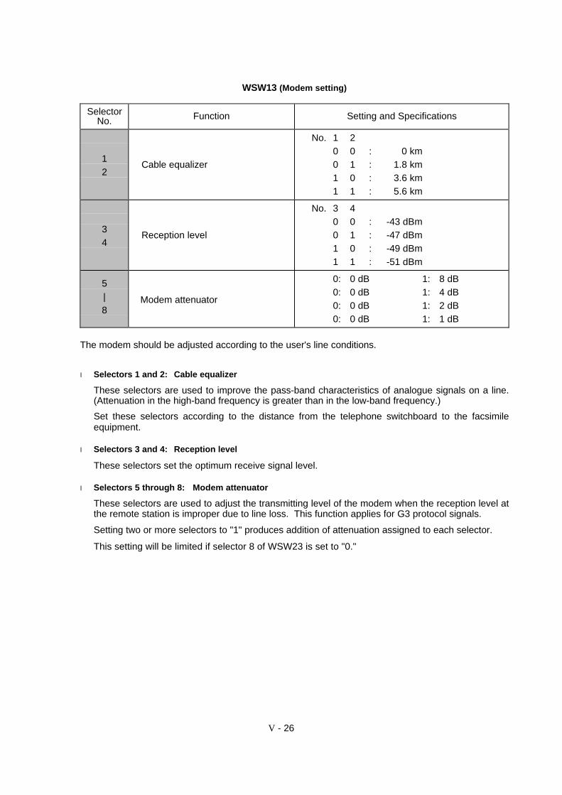
WSW13 (Modem setting)
SelectorNo. Function Setting and Specifications
12
Cable equalizer
No. 1 20 0 : 0 km0 1 : 1.8 km1 0 : 3.6 km1 1 : 5.6 km
34
Reception level
No. 3 40 0 : -43 dBm0 1 : -47 dBm1 0 : -49 dBm1 1 : -51 dBm
5|8
Modem attenuator
0: 0 dB 1: 8 dB0: 0 dB 1: 4 dB0: 0 dB 1: 2 dB0: 0 dB 1: 1 dB
The modem should be adjusted according to the user's line conditions.
l Selectors 1 and 2: Cable equalizer
These selectors are used to improve the pass-band characteristics of analogue signals on a line.(Attenuation in the high-band frequency is greater than in the low-band frequency.)
Set these selectors according to the distance from the telephone switchboard to the facsimileequipment.
l Selectors 3 and 4: Reception level
These selectors set the optimum receive signal level.
l Selectors 5 through 8: Modem attenuator
These selectors are used to adjust the transmitting level of the modem when the reception level atthe remote station is improper due to line loss. This function applies for G3 protocol signals.
Setting two or more selectors to "1" produces addition of attenuation assigned to each selector.
This setting will be limited if selector 8 of WSW23 is set to "0."

V - 27
WSW14 (AUTO ANS facility setting)
SelectorNo. Function Setting and Specifications
1
2
Frequency band selection(Lower limit)
No. 1 20 0 : 13 Hz0 1 : 15 Hz1 0 : 23 Hz1 1 : 20 Hz
34
Frequency band selection(Upper limit)
No. 3 40 0 : 30 Hz0 1 : 55 Hz1 X : 70 Hz
5|8
No. of rings in AUTO ANS mode
No. 5 6 7 80 0 0 0 : Fixed to once0 0 0 1 : Fixed to 2 times0 0 1 0 : Fixed to 3 times0 0 1 1 : Fixed to 4 times0 1 0 0 : 1 to 2 times0 1 0 1 : 1 to 3 times0 1 1 0 : 1 to 4 times0 1 1 1 : 1 to 5 times1 0 0 0 : 2 to 3 times1 0 0 1 : 2 to 4 times1 0 1 0 : 2 to 5 times1 0 1 1 : 2 to 6 times1 1 0 0 : 1 to 10 times1 1 0 1 : 2 to 10 times1 1 1 0 : 3 to 5 times1 1 1 1 : 4 to 10 times
l Selectors 1 through 4: Frequency band selection
These selectors are used to select the frequency band of calling signals for activating the AUTOANS facility.
In the French versions, if the user sets the PBX to OFF from the control panel, the setting made byselectors 1 and 2 will take no effect and the frequency's lower limit will be fixed to 32 Hz. (Even ifthe setting made by these selectors does not apply, it will be printed on the configuration list.)
l Selectors 5 through 8: No. of rings in AUTO ANS mode
These selectors set the number of rings to initiate the AUTO ANS facility.
V - 28
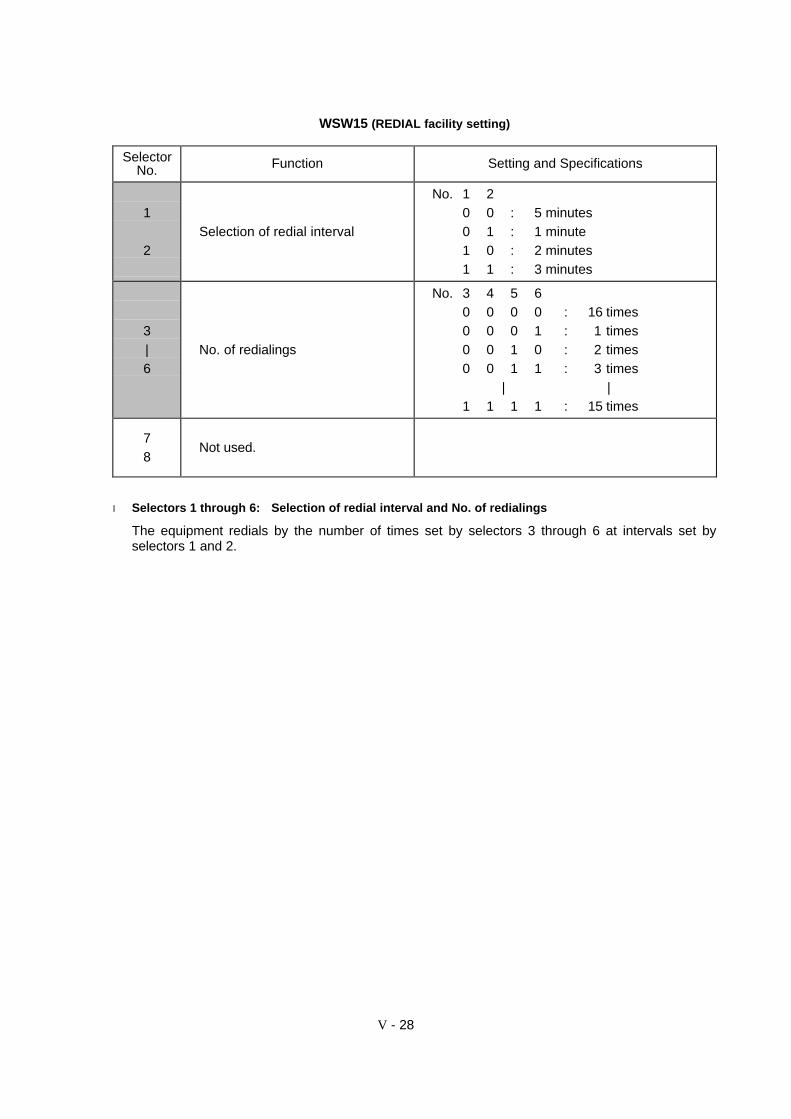
WSW15 (REDIAL facility setting)
SelectorNo. Function Setting and Specifications
1
2Selection of redial interval
No. 1 20 0 : 5 minutes0 1 : 1 minute1 0 : 2 minutes1 1 : 3 minutes
3|6
No. of redialings
No. 3 4 5 60 0 0 0 : 16 times0 0 0 1 : 1 times0 0 1 0 : 2 times0 0 1 1 : 3 times
| |1 1 1 1 : 15 times
78
Not used.
l Selectors 1 through 6: Selection of redial interval and No. of redialings
The equipment redials by the number of times set by selectors 3 through 6 at intervals set byselectors 1 and 2.

V - 29
WSW16 (Function setting 1)
SelectorNo. Function Setting and Specifications
1 Not used.
2 CCITT superfine recommendation 0: OFF 1: ON
3|6
Not used.
7 Max. document length limitation 0: 400 cm 1: 90 cm
8 Stop key pressed during reception 0: Not functional 1: Functional
l Selector 2: CCITT superfine recommendation
If this selector is set to "1," the equipment communicates in CCITT recommended superfine mode(15.4 lines/mm). If it is set to "0," it communicates in native superfine mode.
l Selector 7: Max. document length limitation
This selector is used to select the maximum length of a document to be sent.
l Selector 8: Stop key pressed during reception
If this selector is set to "1," pressing the Stop key can stop the current receiving operation. Thereceived data will be lost.

V - 30
WSW17 (Function setting 2)
SelectorNo. Function Setting and Specifications
1
2Off-hook alarm
No. 1 20 0 : No alarm0 1 : Always valid1 X : Valid except when
'call reservation'is selected.
3 Power failure report output 0: ON 1: OFF
4Calendar clock/prompt alternatedisplay 0: NO 1: YES
5 Calendar clock type 0: U.S.A. type 1: European type
6 Error indication in activity report 0: NO 1: YES
7 Non-ring reception 0: OFF 1: ON
8 Not used.
NOTE: Selector 3 is not applicable to the U.S.A. versions.
l Selectors 1 and 2: Off-hook alarm
These selectors activate or deactivate the alarm function which sounds an alarm when thecommunication is completed with the handset being off the hook.
l Selector 3: Power failure report output
This selector determines whether or not the equipment outputs a power failure report when thepower comes back on.
l Selector 4: Calendar clock/prompt alternate display
If this selector is set to "1," the calendar clock and the prompt "INSERT DOCUMENT" appearalternately on the LCD while the equipment is on standby; if it is set to "0," only the calendar clockappears.
l Selector 5: Calendar clock type
If this selector is set to "0" (USA), the MM/DD/YY hh:mm format applies; if it is set to "1" (Europe),the DD/MM/YY hh:mm format applies: DD is the day, MM is the month, YY is the last two digits ofthe year, hh is the hour, and mm is the minute.
l Selector 6: Error indication in activity report
This selector determines whether or not a communications error code will be printed in the activityreport.
l Selector 7: Non-ring reception
Setting this selector to "1" makes the equipment receive calls without ringer sound if the ring delayis set to 0.
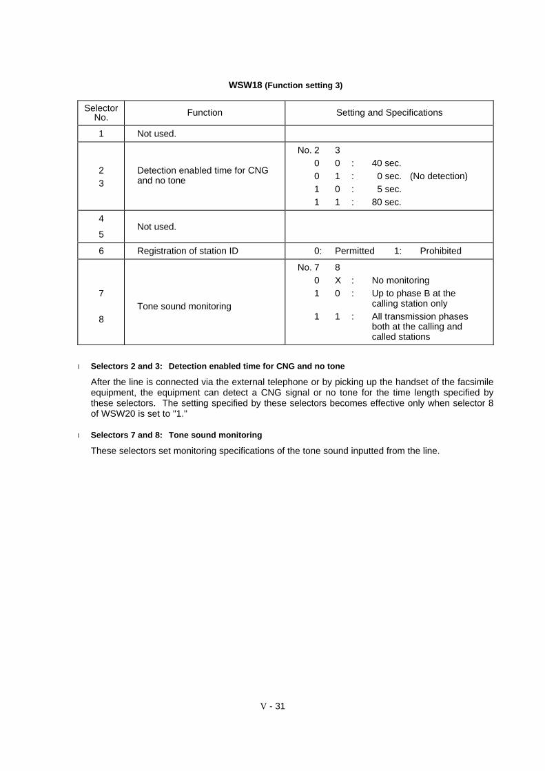
V - 31
WSW18 (Function setting 3)
SelectorNo. Function Setting and Specifications
1 Not used.
23
Detection enabled time for CNGand no tone
No. 2 30 0 : 40 sec.0 1 : 0 sec. (No detection)1 0 : 5 sec.1 1 : 80 sec.
4
5Not used.
6 Registration of station ID 0: Permitted 1: Prohibited
7
8Tone sound monitoring
No. 7 80 X : No monitoring1 0 : Up to phase B at the
calling station only1 1 : All transmission phases
both at the calling andcalled stations
l Selectors 2 and 3: Detection enabled time for CNG and no tone
After the line is connected via the external telephone or by picking up the handset of the facsimileequipment, the equipment can detect a CNG signal or no tone for the time length specified bythese selectors. The setting specified by these selectors becomes effective only when selector 8of WSW20 is set to "1."
l Selectors 7 and 8: Tone sound monitoring
These selectors set monitoring specifications of the tone sound inputted from the line.
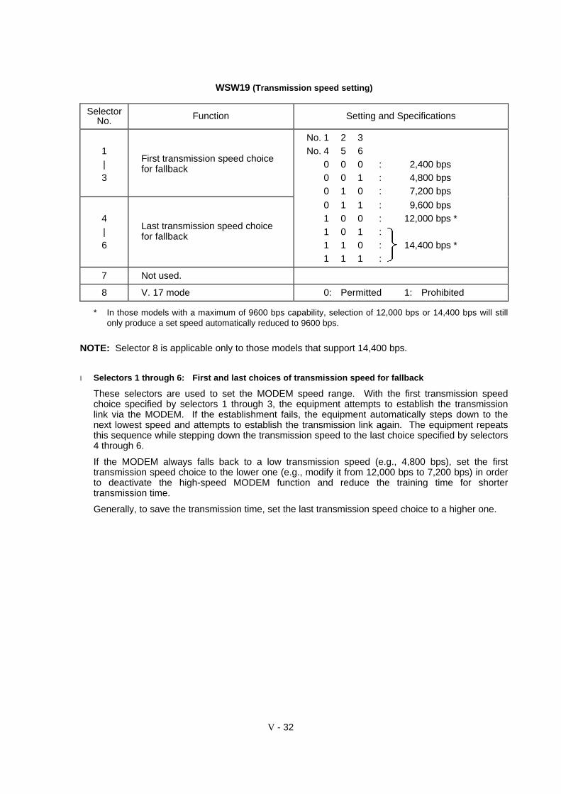
V - 32
WSW19 (Transmission speed setting)
SelectorNo. Function Setting and Specifications
1|3
First transmission speed choicefor fallback
No. 1 2 3No. 4 5 6
0 0 0 : 2,400 bps0 0 1 : 4,800 bps0 1 0 : 7,200 bps
4|6
Last transmission speed choicefor fallback
0 1 1 : 9,600 bps1 0 0 : 12,000 bps *1 0 1 :1 1 0 : 14,400 bps *1 1 1 :
7 Not used.
8 V. 17 mode 0: Permitted 1: Prohibited
* In those models with a maximum of 9600 bps capability, selection of 12,000 bps or 14,400 bps will stillonly produce a set speed automatically reduced to 9600 bps.
NOTE: Selector 8 is applicable only to those models that support 14,400 bps.
l Selectors 1 through 6: First and last choices of transmission speed for fallback
These selectors are used to set the MODEM speed range. With the first transmission speedchoice specified by selectors 1 through 3, the equipment attempts to establish the transmissionlink via the MODEM. If the establishment fails, the equipment automatically steps down to thenext lowest speed and attempts to establish the transmission link again. The equipment repeatsthis sequence while stepping down the transmission speed to the last choice specified by selectors4 through 6.
If the MODEM always falls back to a low transmission speed (e.g., 4,800 bps), set the firsttransmission speed choice to the lower one (e.g., modify it from 12,000 bps to 7,200 bps) in orderto deactivate the high-speed MODEM function and reduce the training time for shortertransmission time.
Generally, to save the transmission time, set the last transmission speed choice to a higher one.
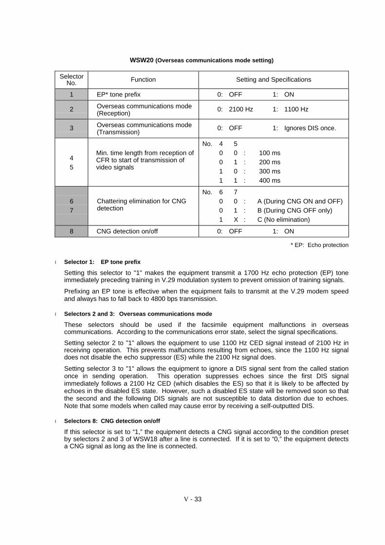
V - 33
WSW20 (Overseas communications mode setting)
SelectorNo. Function Setting and Specifications
1 EP* tone prefix 0: OFF 1: ON
2 Overseas communications mode(Reception)
0: 2100 Hz 1: 1100 Hz
3 Overseas communications mode(Transmission)
0: OFF 1: Ignores DIS once.
45
Min. time length from reception ofCFR to start of transmission ofvideo signals
No. 4 50 0 : 100 ms0 1 : 200 ms1 0 : 300 ms1 1 : 400 ms
67
Chattering elimination for CNGdetection
No. 6 70 0 : A (During CNG ON and OFF)0 1 : B (During CNG OFF only)1 X : C (No elimination)
8 CNG detection on/off 0: OFF 1: ON
* EP: Echo protection
l Selector 1: EP tone prefix
Setting this selector to "1" makes the equipment transmit a 1700 Hz echo protection (EP) toneimmediately preceding training in V.29 modulation system to prevent omission of training signals.
Prefixing an EP tone is effective when the equipment fails to transmit at the V.29 modem speedand always has to fall back to 4800 bps transmission.
l Selectors 2 and 3: Overseas communications mode
These selectors should be used if the facsimile equipment malfunctions in overseascommunications. According to the communications error state, select the signal specifications.
Setting selector 2 to "1" allows the equipment to use 1100 Hz CED signal instead of 2100 Hz inreceiving operation. This prevents malfunctions resulting from echoes, since the 1100 Hz signaldoes not disable the echo suppressor (ES) while the 2100 Hz signal does.
Setting selector 3 to "1" allows the equipment to ignore a DIS signal sent from the called stationonce in sending operation. This operation suppresses echoes since the first DIS signalimmediately follows a 2100 Hz CED (which disables the ES) so that it is likely to be affected byechoes in the disabled ES state. However, such a disabled ES state will be removed soon so thatthe second and the following DIS signals are not susceptible to data distortion due to echoes.Note that some models when called may cause error by receiving a self-outputted DIS.
l Selectors 8: CNG detection on/off
If this selector is set to “1,” the equipment detects a CNG signal according to the condition presetby selectors 2 and 3 of WSW18 after a line is connected. If it is set to “0,” the equipment detectsa CNG signal as long as the line is connected.
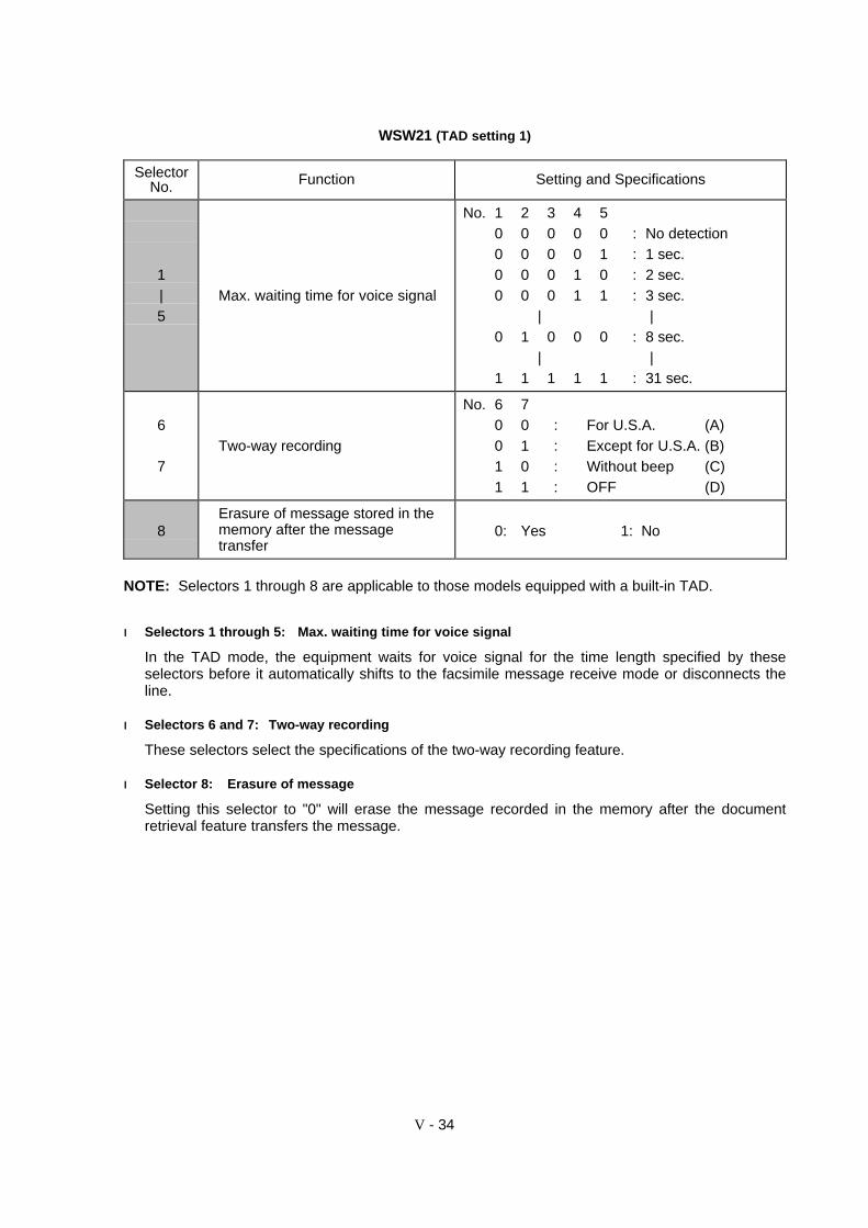
V - 34
WSW21 (TAD setting 1)
SelectorNo. Function Setting and Specifications
1|5
Max. waiting time for voice signal
No. 1 2 3 4 50 0 0 0 0 : No detection0 0 0 0 1 : 1 sec.0 0 0 1 0 : 2 sec.0 0 0 1 1 : 3 sec.
| |0 1 0 0 0 : 8 sec.
| |1 1 1 1 1 : 31 sec.
6
7Two-way recording
No. 6 70 0 : For U.S.A. (A)0 1 : Except for U.S.A. (B)1 0 : Without beep (C)1 1 : OFF (D)
8Erasure of message stored in thememory after the messagetransfer
0: Yes 1: No
NOTE: Selectors 1 through 8 are applicable to those models equipped with a built-in TAD.
ll Selectors 1 through 5: Max. waiting time for voice signal
In the TAD mode, the equipment waits for voice signal for the time length specified by theseselectors before it automatically shifts to the facsimile message receive mode or disconnects theline.
ll Selectors 6 and 7: Two-way recording
These selectors select the specifications of the two-way recording feature.
ll Selector 8: Erasure of message
Setting this selector to "0" will erase the message recorded in the memory after the documentretrieval feature transfers the message.

V - 35
WSW22 (ECM and caller ID setting)
SelectorNo. Function Setting and Specifications
1 ECM* in sending 0: ON 1: OFF
2 ECM* in receiving 0: ON 1: OFF
3 Call Waiting Caller ID 0: ON 1: OFF
4 Not used.
5|8
Acceptable TCF bit error rate (%)(Only at 4800 bps)
0: 0% 1: 8%0: 0% 1: 4%0: 0% 1: 2%0: 0% 1: 1%
* ECM: Error correction mode
NOTE: Selector 3 is applicable to the U.S.A. versions only.
NOTE: Selectors 5 through 8 are applicable to the Chinese, Taiwanese and Asian versions only.
ll Selector 3: Call Waiting Caller ID
Setting this selector to "0" allows the user to decide whether or not to interrupt the current callwhen a new call comes in. If Call Waiting Caller ID service is available in the area and the usersubscribes to it, he/she can see information about his/her incoming call.
ll Selectors 5 through 8: Acceptable TCF bit error rate (%)
Setting two or more selectors to "1" produces addition of percent assigned to each selector. If youset selectors 7 and 8 to "1," the acceptable TCF bit error rate will be 3%.
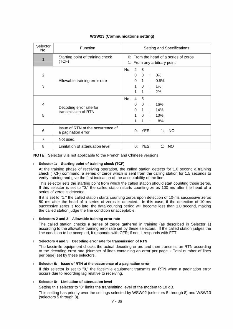
V - 36
WSW23 (Communications setting)
SelectorNo. Function Setting and Specifications
1Starting point of training check(TCF)
0: From the head of a series of zeros1: From any arbitrary point
2
3Allowable training error rate
No. 2 30 0 : 0%0 1 : 0.5%1 0 : 1%1 1 : 2%
4
5
Decoding error rate fortransmission of RTN
No. 4 50 0 : 16%0 1 : 14%1 0 : 10%1 1 : 8%
6Issue of RTN at the occurrence ofa pagination error 0: YES 1: NO
7 Not used.
8 Limitation of attenuation level 0: YES 1: NO
NOTE: Selector 8 is not applicable to the French and Chinese versions.
l Selector 1: Starting point of training check (TCF)
At the training phase of receiving operation, the called station detects for 1.0 second a trainingcheck (TCF) command, a series of zeros which is sent from the calling station for 1.5 seconds toverify training and give the first indication of the acceptability of the line.This selector sets the starting point from which the called station should start counting those zeros.If this selector is set to "0," the called station starts counting zeros 100 ms after the head of aseries of zeros is detected.If it is set to "1," the called station starts counting zeros upon detection of 10-ms successive zeros50 ms after the head of a series of zeros is detected. In this case, if the detection of 10-mssuccessive zeros is too late, the data counting period will become less than 1.0 second, makingthe called station judge the line condition unacceptable.
l Selectors 2 and 3: Allowable training error rate
The called station checks a series of zeros gathered in training (as described in Selector 1)according to the allowable training error rate set by these selectors. If the called station judges theline condition to be accepted, it responds with CFR; if not, it responds with FTT.
l Selectors 4 and 5: Decoding error rate for transmission of RTN
The facsimile equipment checks the actual decoding errors and then transmits an RTN accordingto the decoding error rate (Number of lines containing an error per page ÷ Total number of linesper page) set by these selectors.
l Selector 6: Issue of RTN at the occurrence of a pagination error
If this selector is set to "0," the facsimile equipment transmits an RTN when a pagination erroroccurs due to recording lag relative to receiving.
l Selector 8: Limitation of attenuation level
Setting this selector to "0" limits the transmitting level of the modem to 10 dB.This setting has priority over the settings selected by WSW02 (selectors 5 through 8) and WSW13(selectors 5 through 8).
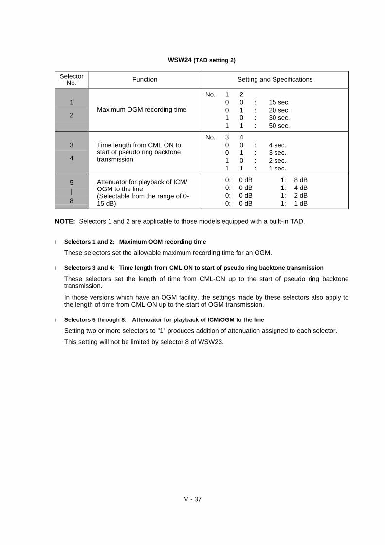
V - 37
WSW24 (TAD setting 2)
SelectorNo. Function Setting and Specifications
1
2Maximum OGM recording time
No. 1 20 0 : 15 sec.0 1 : 20 sec.1 0 : 30 sec.1 1 : 50 sec.
3
4
Time length from CML ON tostart of pseudo ring backtonetransmission
No. 3 40 0 : 4 sec.0 1 : 3 sec.1 0 : 2 sec.1 1 : 1 sec.
5|8
Attenuator for playback of ICM/OGM to the line(Selectable from the range of 0-15 dB)
0: 0 dB 1: 8 dB0: 0 dB 1: 4 dB0: 0 dB 1: 2 dB0: 0 dB 1: 1 dB
NOTE: Selectors 1 and 2 are applicable to those models equipped with a built-in TAD.
l Selectors 1 and 2: Maximum OGM recording time
These selectors set the allowable maximum recording time for an OGM.
l Selectors 3 and 4: Time length from CML ON to start of pseudo ring backtone transmission
These selectors set the length of time from CML-ON up to the start of pseudo ring backtonetransmission.
In those versions which have an OGM facility, the settings made by these selectors also apply tothe length of time from CML-ON up to the start of OGM transmission.
l Selectors 5 through 8: Attenuator for playback of ICM/OGM to the line
Setting two or more selectors to "1" produces addition of attenuation assigned to each selector.
This setting will not be limited by selector 8 of WSW23.

V - 38
WSW25 (TAD setting 3)
SelectorNo. Function Setting and Specifications
1|4
Not used.
5
|
7
Pause between paging numberand PIN
No. 5 6 70 0 0 : 2 sec.0 0 1 : 4 sec.0 1 0 : 6 sec.0 1 1 : 8 sec.1 0 0 : 10 sec.1 0 1 : 12 sec.1 1 0 : 14 sec.1 1 1 : 16 sec.
8 Not used.
NOTE: Selectors 5 through 7 are applicable to the U.S.A. and Canadian versions.
l Selectors 5 through 7: Pause between paging number and PIN
These selectors set the pause time between a telephone number being paged and PIN (privateidentification number) for the paging feature.
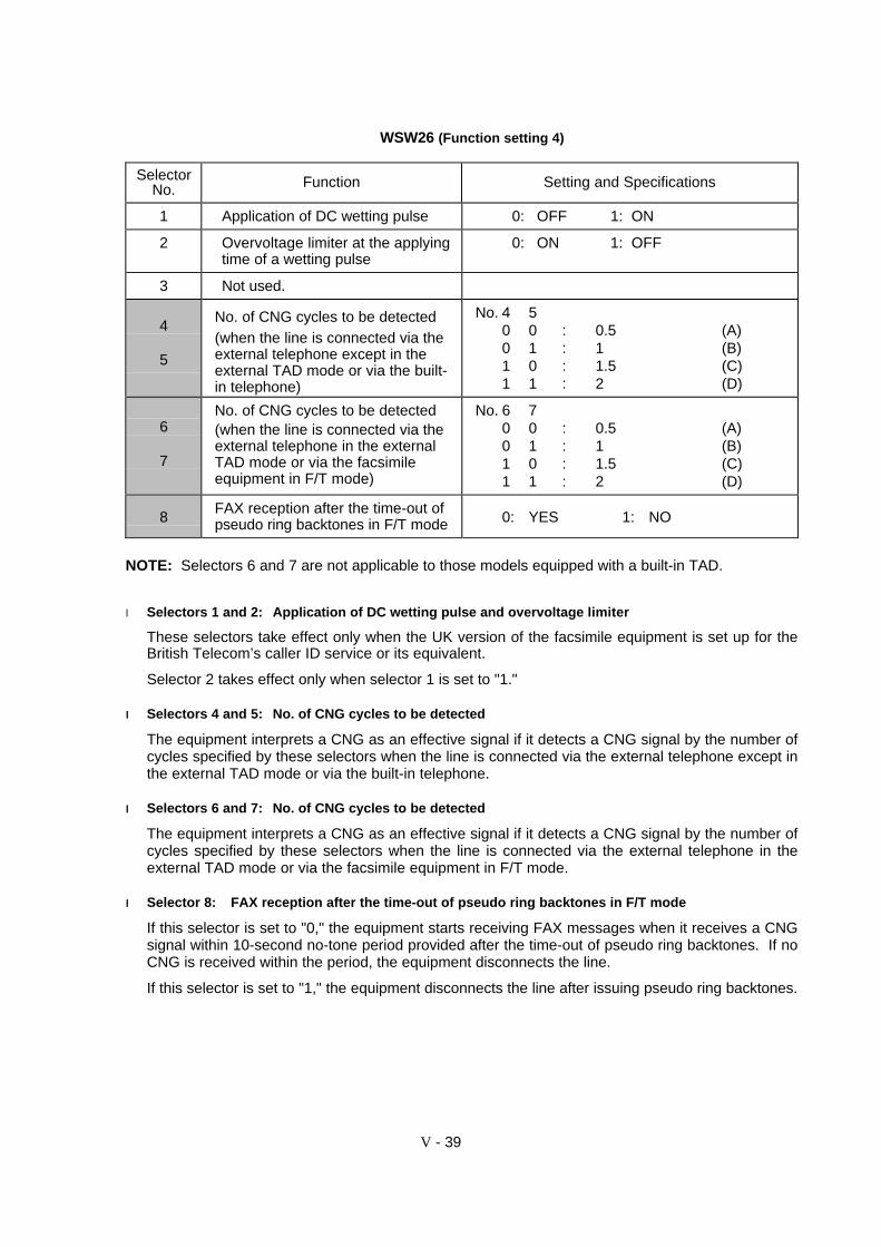
V - 39
WSW26 (Function setting 4)
SelectorNo. Function Setting and Specifications
1 Application of DC wetting pulse 0: OFF 1: ON
2 Overvoltage limiter at the applyingtime of a wetting pulse
0: ON 1: OFF
3 Not used.
4
5
No. of CNG cycles to be detected(when the line is connected via theexternal telephone except in theexternal TAD mode or via the built-in telephone)
No. 4 50 0 : 0.5 (A)0 1 : 1 (B)1 0 : 1.5 (C)1 1 : 2 (D)
6
7
No. of CNG cycles to be detected(when the line is connected via theexternal telephone in the externalTAD mode or via the facsimileequipment in F/T mode)
No. 6 70 0 : 0.5 (A)0 1 : 1 (B)1 0 : 1.5 (C)1 1 : 2 (D)
8FAX reception after the time-out ofpseudo ring backtones in F/T mode 0: YES 1: NO
NOTE: Selectors 6 and 7 are not applicable to those models equipped with a built-in TAD.
l Selectors 1 and 2: Application of DC wetting pulse and overvoltage limiter
These selectors take effect only when the UK version of the facsimile equipment is set up for theBritish Telecom’s caller ID service or its equivalent.
Selector 2 takes effect only when selector 1 is set to "1."
ll Selectors 4 and 5: No. of CNG cycles to be detected
The equipment interprets a CNG as an effective signal if it detects a CNG signal by the number ofcycles specified by these selectors when the line is connected via the external telephone except inthe external TAD mode or via the built-in telephone.
ll Selectors 6 and 7: No. of CNG cycles to be detected
The equipment interprets a CNG as an effective signal if it detects a CNG signal by the number ofcycles specified by these selectors when the line is connected via the external telephone in theexternal TAD mode or via the facsimile equipment in F/T mode.
ll Selector 8: FAX reception after the time-out of pseudo ring backtones in F/T mode
If this selector is set to "0," the equipment starts receiving FAX messages when it receives a CNGsignal within 10-second no-tone period provided after the time-out of pseudo ring backtones. If noCNG is received within the period, the equipment disconnects the line.
If this selector is set to "1," the equipment disconnects the line after issuing pseudo ring backtones.
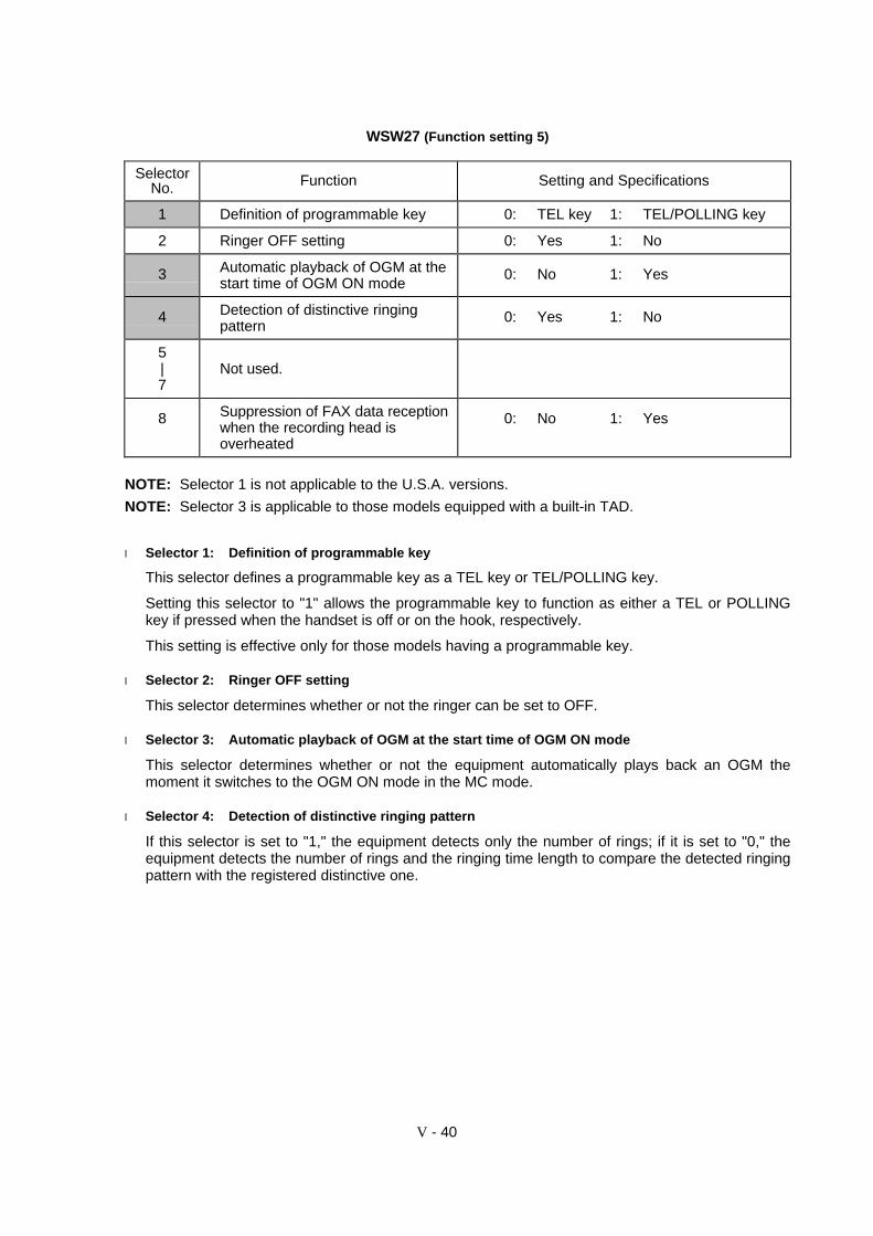
V - 40
WSW27 (Function setting 5)
SelectorNo. Function Setting and Specifications
1 Definition of programmable key 0: TEL key 1: TEL/POLLING key
2 Ringer OFF setting 0: Yes 1: No
3 Automatic playback of OGM at thestart time of OGM ON mode
0: No 1: Yes
4 Detection of distinctive ringingpattern
0: Yes 1: No
5|7
Not used.
8 Suppression of FAX data receptionwhen the recording head isoverheated
0: No 1: Yes
NOTE: Selector 1 is not applicable to the U.S.A. versions.
NOTE: Selector 3 is applicable to those models equipped with a built-in TAD.
l Selector 1: Definition of programmable key
This selector defines a programmable key as a TEL key or TEL/POLLING key.
Setting this selector to "1" allows the programmable key to function as either a TEL or POLLINGkey if pressed when the handset is off or on the hook, respectively.
This setting is effective only for those models having a programmable key.
l Selector 2: Ringer OFF setting
This selector determines whether or not the ringer can be set to OFF.
l Selector 3: Automatic playback of OGM at the start time of OGM ON mode
This selector determines whether or not the equipment automatically plays back an OGM themoment it switches to the OGM ON mode in the MC mode.
l Selector 4: Detection of distinctive ringing pattern
If this selector is set to "1," the equipment detects only the number of rings; if it is set to "0," theequipment detects the number of rings and the ringing time length to compare the detected ringingpattern with the registered distinctive one.
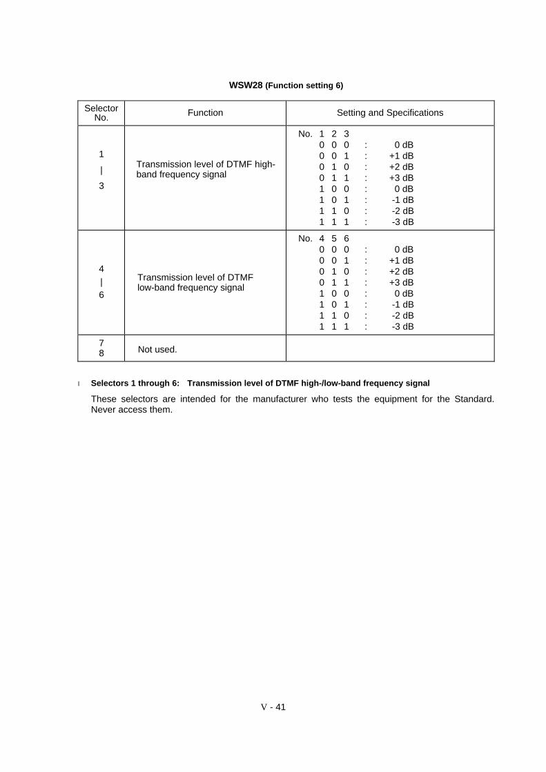
V - 41
WSW28 (Function setting 6)
SelectorNo. Function Setting and Specifications
1
|
3
Transmission level of DTMF high-band frequency signal
No. 1 2 30 0 0 : 0 dB0 0 1 : +1 dB0 1 0 : +2 dB0 1 1 : +3 dB1 0 0 : 0 dB1 0 1 : -1 dB1 1 0 : -2 dB1 1 1 : -3 dB
4|6
Transmission level of DTMFlow-band frequency signal
No. 4 5 60 0 0 : 0 dB0 0 1 : +1 dB0 1 0 : +2 dB0 1 1 : +3 dB1 0 0 : 0 dB1 0 1 : -1 dB1 1 0 : -2 dB1 1 1 : -3 dB
78 Not used.
l Selectors 1 through 6: Transmission level of DTMF high-/low-band frequency signal
These selectors are intended for the manufacturer who tests the equipment for the Standard.Never access them.
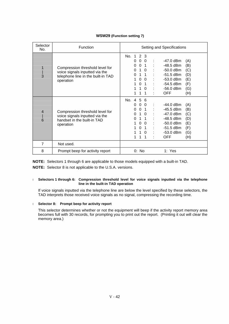
V - 42
WSW29 (Function setting 7)
SelectorNo. Function Setting and Specifications
1|3
Compression threshold level forvoice signals inputted via thetelephone line in the built-in TADoperation
No. 1 2 30 0 0 : -47.0 dBm (A)0 0 1 : -48.5 dBm (B)0 1 0 : -50.0 dBm (C)0 1 1 : -51.5 dBm (D)1 0 0 : -53.0 dBm (E)1 0 1 : -54.5 dBm (F)1 1 0 : -56.0 dBm (G)1 1 1 : OFF (H)
4|6
Compression threshold level forvoice signals inputted via thehandset in the built-in TADoperation
No. 4 5 60 0 0 : -44.0 dBm (A)0 0 1 : -45.5 dBm (B)0 1 0 : -47.0 dBm (C)0 1 1 : -48.5 dBm (D)1 0 0 : -50.0 dBm (E)1 0 1 : -51.5 dBm (F)1 1 0 : -53.0 dBm (G)1 1 1 : OFF (H)
7 Not used.
8 Prompt beep for activity report 0: No 1: Yes
NOTE: Selectors 1 through 6 are applicable to those models equipped with a built-in TAD.
NOTE: Selector 8 is not applicable to the U.S.A. versions.
l Selectors 1 through 6: Compression threshold level for voice signals inputted via the telephoneline in the built-in TAD operation
If voice signals inputted via the telephone line are below the level specified by these selectors, theTAD interprets those received voice signals as no signal, compressing the recording time.
l Selector 8: Prompt beep for activity report
This selector determines whether or not the equipment will beep if the activity report memory areabecomes full with 30 records, for prompting you to print out the report. (Printing it out will clear thememory area.)
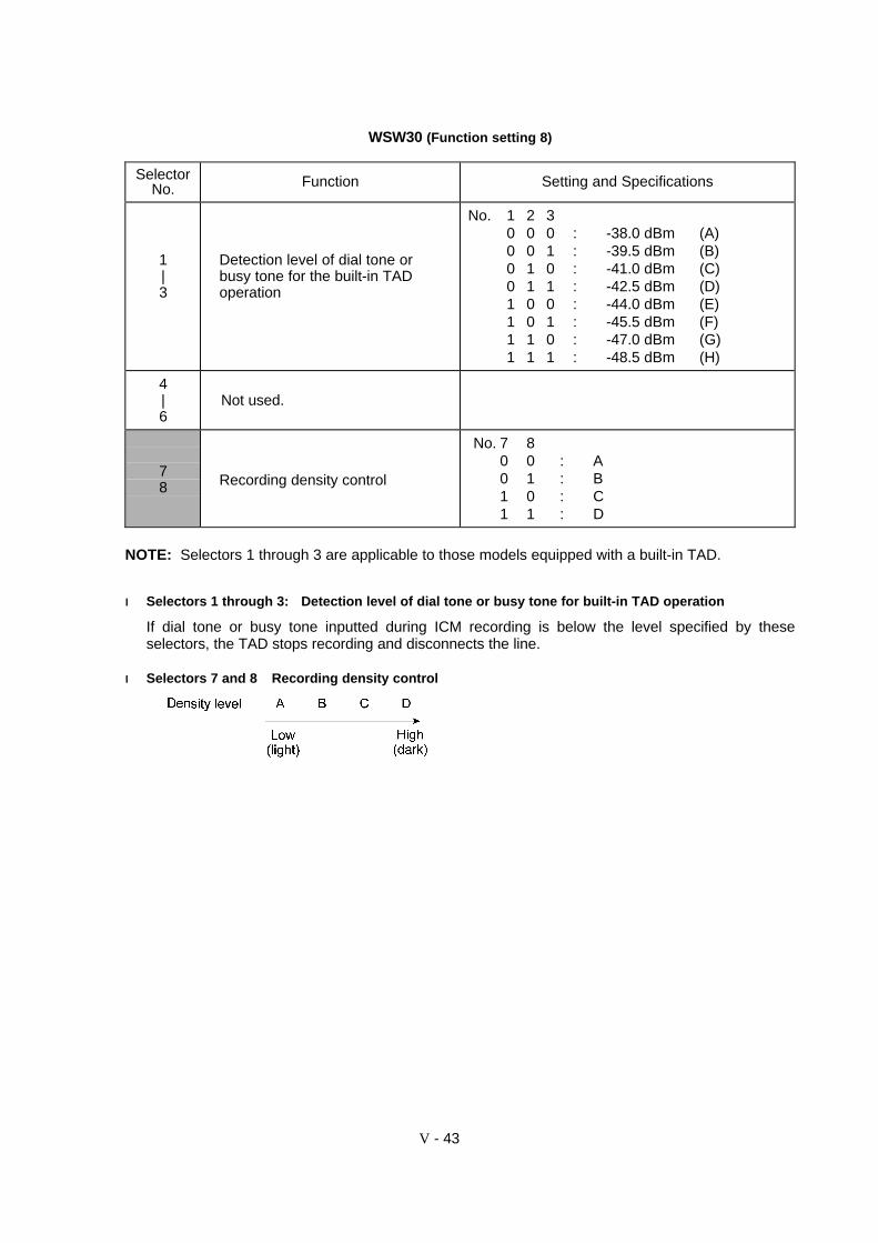
V - 43
WSW30 (Function setting 8)
SelectorNo. Function Setting and Specifications
1|3
Detection level of dial tone orbusy tone for the built-in TADoperation
No. 1 2 30 0 0 : -38.0 dBm (A)0 0 1 : -39.5 dBm (B)0 1 0 : -41.0 dBm (C)0 1 1 : -42.5 dBm (D)1 0 0 : -44.0 dBm (E)1 0 1 : -45.5 dBm (F)1 1 0 : -47.0 dBm (G)1 1 1 : -48.5 dBm (H)
4|6
Not used.
78 Recording density control
No. 7 80 0 : A0 1 : B1 0 : C1 1 : D
NOTE: Selectors 1 through 3 are applicable to those models equipped with a built-in TAD.
ll Selectors 1 through 3: Detection level of dial tone or busy tone for built-in TAD operation
If dial tone or busy tone inputted during ICM recording is below the level specified by theseselectors, the TAD stops recording and disconnects the line.
ll Selectors 7 and 8 Recording density control
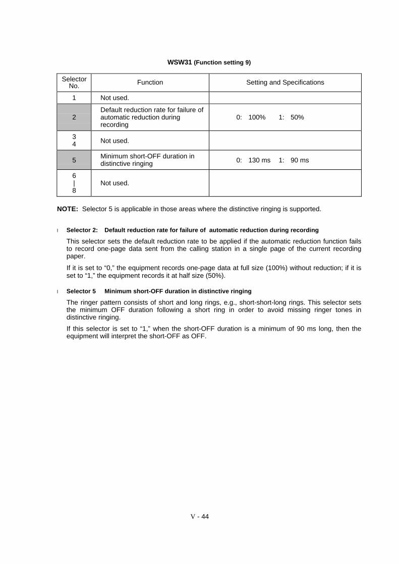
V - 44
WSW31 (Function setting 9)
SelectorNo. Function Setting and Specifications
1 Not used.
2Default reduction rate for failure ofautomatic reduction duringrecording
0: 100% 1: 50%
34 Not used.
5Minimum short-OFF duration indistinctive ringing 0: 130 ms 1: 90 ms
6|8
Not used.
NOTE: Selector 5 is applicable in those areas where the distinctive ringing is supported.
l Selector 2: Default reduction rate for failure of automatic reduction during recording
This selector sets the default reduction rate to be applied if the automatic reduction function failsto record one-page data sent from the calling station in a single page of the current recordingpaper.
If it is set to “0,” the equipment records one-page data at full size (100%) without reduction; if it isset to “1,” the equipment records it at half size (50%).
l Selector 5 Minimum short-OFF duration in distinctive ringing
The ringer pattern consists of short and long rings, e.g., short-short-long rings. This selector setsthe minimum OFF duration following a short ring in order to avoid missing ringer tones indistinctive ringing.
If this selector is set to “1,” when the short-OFF duration is a minimum of 90 ms long, then theequipment will interpret the short-OFF as OFF.
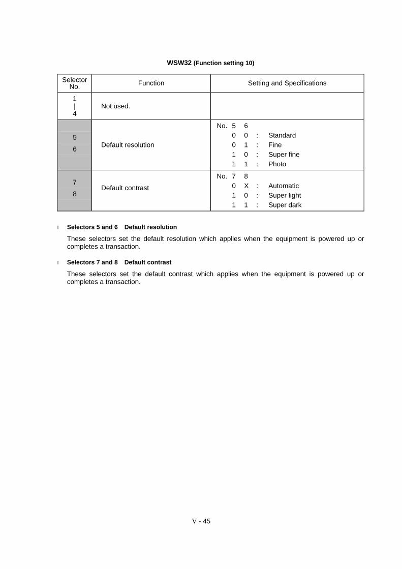
V - 45
WSW32 (Function setting 10)
SelectorNo. Function Setting and Specifications
1|4
Not used.
5
6Default resolution
No. 5 60 0 : Standard0 1 : Fine1 0 : Super fine1 1 : Photo
7
8Default contrast
No. 7 80 X : Automatic1 0 : Super light1 1 : Super dark
l Selectors 5 and 6 Default resolution
These selectors set the default resolution which applies when the equipment is powered up orcompletes a transaction.
l Selectors 7 and 8 Default contrast
These selectors set the default contrast which applies when the equipment is powered up orcompletes a transaction.
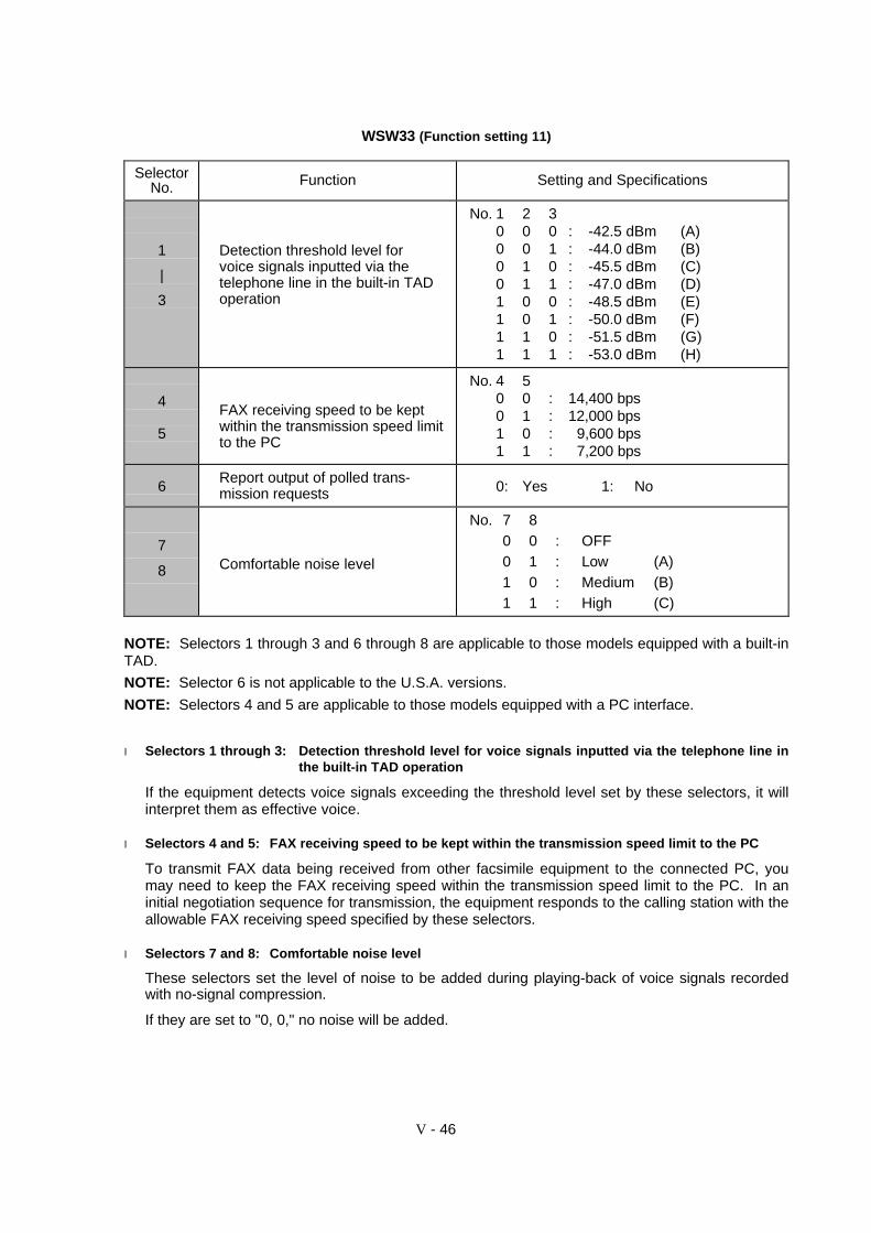
V - 46
WSW33 (Function setting 11)
SelectorNo. Function Setting and Specifications
1
|
3
Detection threshold level forvoice signals inputted via thetelephone line in the built-in TADoperation
No. 1 2 30 0 0 : -42.5 dBm (A)0 0 1 : -44.0 dBm (B)0 1 0 : -45.5 dBm (C)0 1 1 : -47.0 dBm (D)1 0 0 : -48.5 dBm (E)1 0 1 : -50.0 dBm (F)1 1 0 : -51.5 dBm (G)1 1 1 : -53.0 dBm (H)
4
5
FAX receiving speed to be keptwithin the transmission speed limitto the PC
No. 4 50 0 : 14,400 bps0 1 : 12,000 bps1 0 : 9,600 bps1 1 : 7,200 bps
6Report output of polled trans-mission requests 0: Yes 1: No
7
8 Comfortable noise level
No. 7 80 0 : OFF0 1 : Low (A)1 0 : Medium (B)1 1 : High (C)
NOTE: Selectors 1 through 3 and 6 through 8 are applicable to those models equipped with a built-inTAD.
NOTE: Selector 6 is not applicable to the U.S.A. versions.
NOTE: Selectors 4 and 5 are applicable to those models equipped with a PC interface.
l Selectors 1 through 3: Detection threshold level for voice signals inputted via the telephone line inthe built-in TAD operation
If the equipment detects voice signals exceeding the threshold level set by these selectors, it willinterpret them as effective voice.
l Selectors 4 and 5: FAX receiving speed to be kept within the transmission speed limit to the PC
To transmit FAX data being received from other facsimile equipment to the connected PC, youmay need to keep the FAX receiving speed within the transmission speed limit to the PC. In aninitial negotiation sequence for transmission, the equipment responds to the calling station with theallowable FAX receiving speed specified by these selectors.
l Selectors 7 and 8: Comfortable noise level
These selectors set the level of noise to be added during playing-back of voice signals recordedwith no-signal compression.
If they are set to "0, 0," no noise will be added.

V - 47
WSW34 (Function setting 12)
SelectorNo. Function Setting and Specifications
1
|
3
Erasing time length of ICM tonerecorded preceding the tonedetection starting point in the caseof automatic line disconnectiondue to no voice signal received
No. 1 2 30 0 0 : 0 sec.0 0 1 : 1 sec.0 1 0 : 2 sec.0 1 1 : 3 sec.1 0 0 : 4 sec.1 0 1 : 5 sec.1 1 0 : 6 sec.1 1 1 : 7 sec.
4
5
No. of CNG cycles to be detected(when the line is connected via theexternal telephone in the externalTAD mode or via the facsimileequipment in F/T or TAD mode)
No. 4 50 0 : 0.5 (A)0 1 : 1 (B)1 0 : 1.5 (C)1 1 : 2 (D)
6
7
Number of DTMF tone signals forinhibiting the detection of CNGduring external TAD operation
No. 6 70 0 : 30 1 : 21 0 : 11 1 : OFF
8 Not used.
NOTE: Selectors 1 through 5 are applicable to those models equipped with a built-in TAD.
l Selectors 1 through 3: Erasing time length of ICM tone recorded preceding the tone detectionstarting point in the case of automatic line disconnection due to no voicesignal received
If the equipment has disconnected the line after detection of disconnection tone in ICM recording,it erases tone recorded preceding the tone detection starting point for the time length set by theseselectors.
l Selectors 4 and 5: No. of CNG cycles to be detected
The equipment interprets a CNG as an effective signal if it detects a CNG signal by the number ofcycles specified by these selectors in any of the following cases:
• when the line is connected via the external telephone in the external TAD mode.
• when the line is connected via the facsimile equipment in F/T or TAD mode.
l Selectors 6 and 7: Number of DTMF tone signals for inhibiting the detection of CNG during externalTAD operation
If the equipment receives this specified number of DTMF tone signals during external TADoperation, it will not detect CNG afterwards.
If these selectors are set to "1, 1," the CNG detection will not be inhibited.
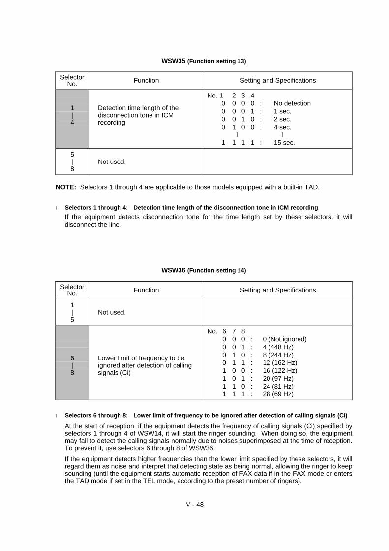
V - 48
WSW35 (Function setting 13)
SelectorNo. Function Setting and Specifications
1|4
Detection time length of thedisconnection tone in ICMrecording
No. 1 2 3 40 0 0 0 : No detection0 0 0 1 : 1 sec.0 0 1 0 : 2 sec.0 1 0 0 : 4 sec.
I I1 1 1 1 : 15 sec.
5|8
Not used.
NOTE: Selectors 1 through 4 are applicable to those models equipped with a built-in TAD.
l Selectors 1 through 4: Detection time length of the disconnection tone in ICM recording
If the equipment detects disconnection tone for the time length set by these selectors, it willdisconnect the line.
WSW36 (Function setting 14)
SelectorNo. Function Setting and Specifications
1|5
Not used.
6|8
Lower limit of frequency to beignored after detection of callingsignals (Ci)
No. 6 7 80 0 0 : 0 (Not ignored)0 0 1 : 4 (448 Hz)0 1 0 : 8 (244 Hz)0 1 1 : 12 (162 Hz)1 0 0 : 16 (122 Hz)1 0 1 : 20 (97 Hz)1 1 0 : 24 (81 Hz)1 1 1 : 28 (69 Hz)
l Selectors 6 through 8: Lower limit of frequency to be ignored after detection of calling signals (Ci)
At the start of reception, if the equipment detects the frequency of calling signals (Ci) specified byselectors 1 through 4 of WSW14, it will start the ringer sounding. When doing so, the equipmentmay fail to detect the calling signals normally due to noises superimposed at the time of reception.To prevent it, use selectors 6 through 8 of WSW36.
If the equipment detects higher frequencies than the lower limit specified by these selectors, it willregard them as noise and interpret that detecting state as being normal, allowing the ringer to keepsounding (until the equipment starts automatic reception of FAX data if in the FAX mode or entersthe TAD mode if set in the TEL mode, according to the preset number of ringers).

V - 49
WSW37 (Function setting 15)
SelectorNo. Function Setting and Specifications
1|8
Not used.
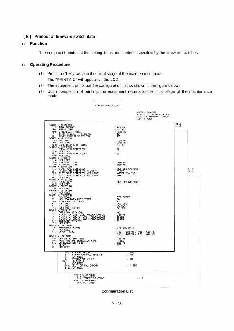
V - 50
[ B ] Printout of firmware switch data
nn Function
The equipment prints out the setting items and contents specified by the firmware switches.
nn Operating Procedure
(1) Press the 1 key twice in the initial stage of the maintenance mode.
The "PRINTING" will appear on the LCD.
(2) The equipment prints out the configuration list as shown in the figure below.
(3) Upon completion of printing, the equipment returns to the initial stage of the maintenancemode.
Configuration List
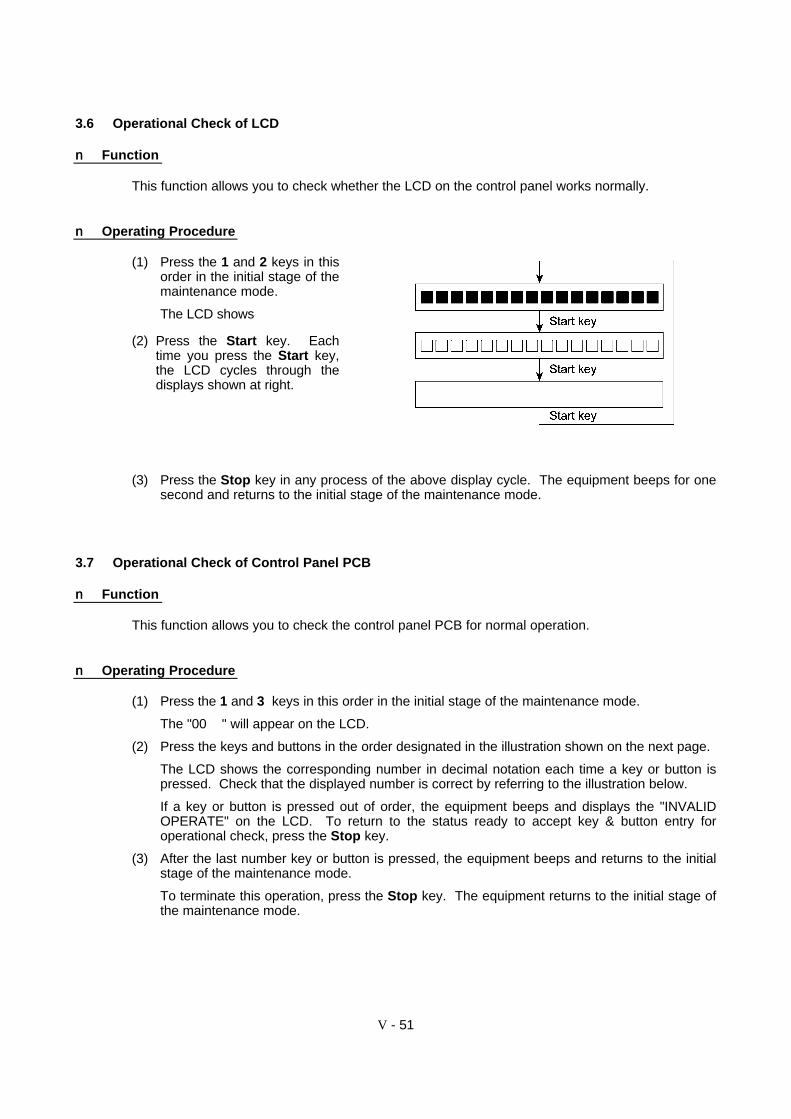
V - 51
3.6 Operational Check of LCD
nn Function
This function allows you to check whether the LCD on the control panel works normally.
nn Operating Procedure
(1) Press the 1 and 2 keys in thisorder in the initial stage of themaintenance mode.
The LCD shows
(2) Press the Start key. Eachtime you press the Start key,the LCD cycles through thedisplays shown at right.
(3) Press the Stop key in any process of the above display cycle. The equipment beeps for onesecond and returns to the initial stage of the maintenance mode.
3.7 Operational Check of Control Panel PCB
nn Function
This function allows you to check the control panel PCB for normal operation.
nn Operating Procedure
(1) Press the 1 and 3 keys in this order in the initial stage of the maintenance mode.
The "00 " will appear on the LCD.
(2) Press the keys and buttons in the order designated in the illustration shown on the next page.
The LCD shows the corresponding number in decimal notation each time a key or button ispressed. Check that the displayed number is correct by referring to the illustration below.
If a key or button is pressed out of order, the equipment beeps and displays the "INVALIDOPERATE" on the LCD. To return to the status ready to accept key & button entry foroperational check, press the Stop key.
(3) After the last number key or button is pressed, the equipment beeps and returns to the initialstage of the maintenance mode.
To terminate this operation, press the Stop key. The equipment returns to the initial stage ofthe maintenance mode.
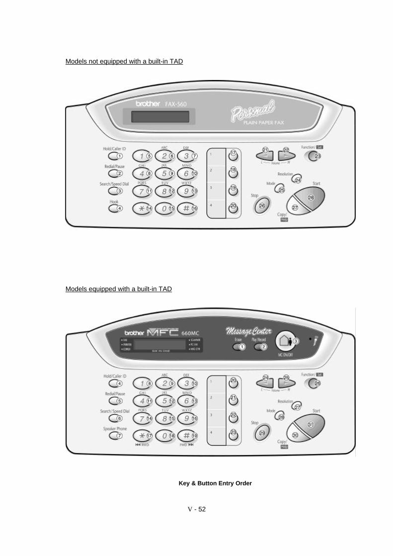
V - 52
Models not equipped with a built-in TAD
Models equipped with a built-in TAD
Key & Button Entry Order

V - 53
3.8 Sensor Operational Check
nn Function
This function allows you to check that the seven sensors (document front sensor, document rearsensor, cover sensor, hook switch*, registration sensor, ribbon sensor, and arm HP switch) operatecorrectly.
(*In the models not equipped with handset, the hook switch serves no function.)
nn Operating Procedure
(1) Press the 3 and 2 keys in this order in the initial stage of the maintenance mode. Theequipment sounds 1100 Hz and 400 Hz tones cyclically through the following volumes fortesting the speaker.
To disable the speaker, press the Function key (American models) or Menu key (Europeanmodels). With the key, you may toggle the speaker on and off.
If the sensing status are as listed below, the LCD will show the following:
"FRERCPHRXCH 0" on the models not equipped with handset
"FRERCPHRXCHHK 0" on other models
Given below is the relationship between the LCD indication, sensor name and sensor status.
LCD Sensors Sensing status
FRE Document front and rear sensors No document detected.RC Cover sensor Control panel ASSY closed.PH Registration sensor Recording paper loadedRX Ribbon sensor Ribbon cartridge loaded.HK Hook switch On-hook state.CH Arm HP switch (on the drive unit) Switching arm out of the home position.
(2) Change the detecting conditions and check that the displayed letters disappear. For example,insert a document through the document front (or rear) sensor and check that the "F" ( or "E")of the FRE disappears.
(3) To stop this operation, press the Stop key. The equipment beeps for one second and returnsto the initial stage of the maintenance mode.
In this area a numeral appears, indicatingthe number of communications recordsprinted out at the factory for testing.
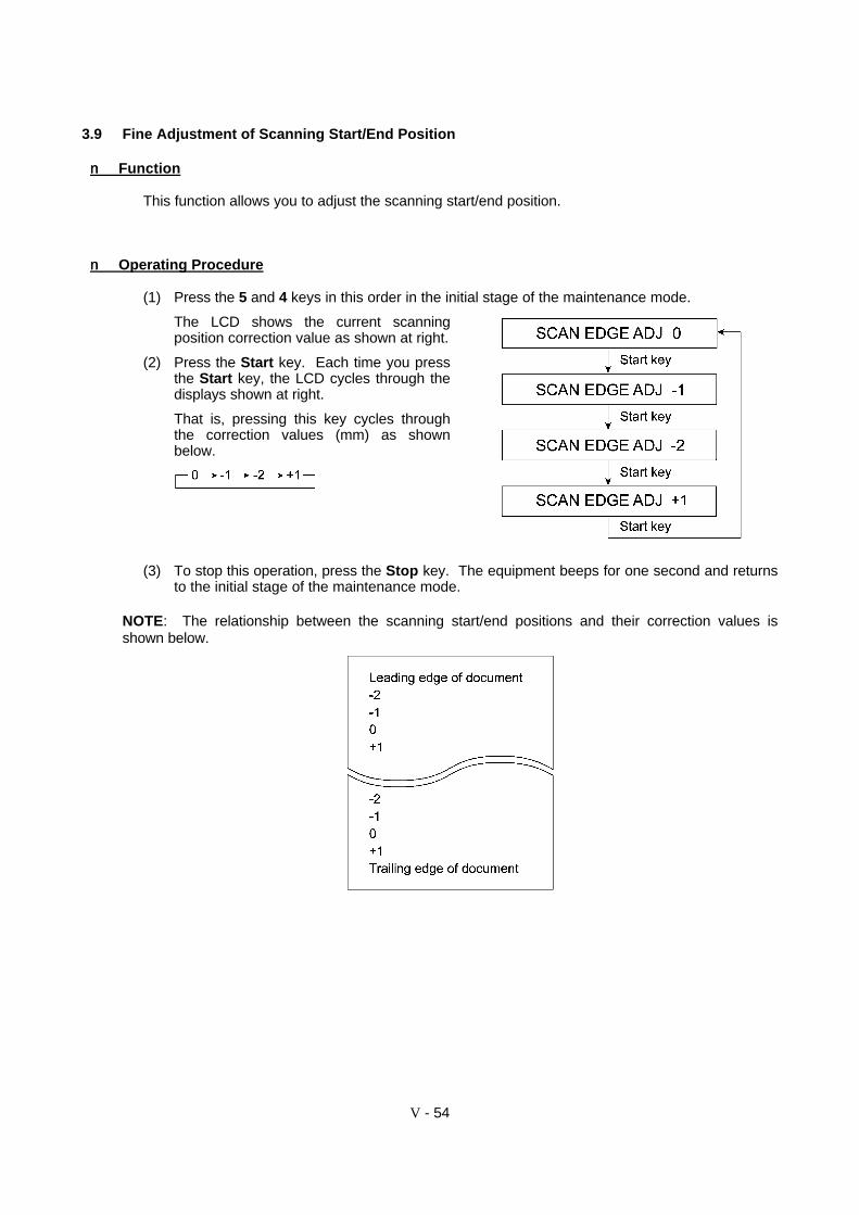
V - 54
3.9 Fine Adjustment of Scanning Start/End Position
nn Function
This function allows you to adjust the scanning start/end position.
nn Operating Procedure
(1) Press the 5 and 4 keys in this order in the initial stage of the maintenance mode.
The LCD shows the current scanningposition correction value as shown at right.
(2) Press the Start key. Each time you pressthe Start key, the LCD cycles through thedisplays shown at right.
That is, pressing this key cycles throughthe correction values (mm) as shownbelow.
(3) To stop this operation, press the Stop key. The equipment beeps for one second and returnsto the initial stage of the maintenance mode.
NOTE: The relationship between the scanning start/end positions and their correction values isshown below.

V - 55
3.10 CIS Scanner Area Setting
nn Function
The equipment sets the CIS scanner area and stores it into the EEPROM.
nn Operating Procedure
(1) Press the 5 key twice in the initial stage of the maintenance mode.
The "SCANNER AREA SET" and "WHITE LEVEL INIT" will appear on the LCD in this order.
The equipment checks and sets the area to be scanned.
If no error is noted, the equipment returns to the initial stage of the maintenance mode.
If any error is noted, the "SCANNER ERROR" will appear on the LCD. To return theequipment to the initial stage of the maintenance mode, press the Stop key.
3.11 EEPROM Customizing
nn Function
This function allows you to customize the EEPROM according to language, function settings, andfirmware switch settings. The customizing codes list is given in Appendix 1.
NOTE: If you replace the main PCB, be sure to carry out this procedure.
nn Operating Procedure
(1) Press the 7 and 4 keys in this order in the initial stage of the maintenance mode.
The current customizing code (e.g., 9001 in the case of FAX560 U.S.A. versions) appears.
(2) Enter the desired customizing code (e.g., 0002 in the case of FAX580MC Canadian versions).
The newly entered code appears.
NOTE: If a wrong 4-digit code is entered, the equipment will malfunction.
(3) Press the Start key.
The equipment saves the setting and returns to the initial stage of the maintenance mode.
If you press the Stop key or no keys are pressed for one minute in the above procedure, theequipment stops the procedure and returns to the initial stage of the maintenance mode.
V - 56
3.12 Equipment Error Code Indication
nn Function
This function displays an error code of the last error on the LCD.
nn Operating Procedure
(1) Press the 8 and 2 keys in this order in the initial stage of the maintenance mode.
The LCD shows the "MACHINE ERROR _ _" (for 2-digit error code indication) or "MACHINEERR _ _ _ _" (for 4-digit error code indication).
(2) To stop this operation and return the equipment to the initial stage of the maintenance mode,press the Stop key.
3.13 Output of Transmission Log to the Telephone Line
nn Function
This function outputs the transmission log (that the equipment has stored about the latesttransmission) to the telephone line. It allows the service personnel to receive the transmission logof the user's equipment at a remote location and use it for analyzing problems arising in the user'sequipment.
nn Operating Procedure
(1) If the user's equipment has a transmission-related problem, call the user's equipment at aremote location from your equipment.
(2) If the line is connected, have the user perform the following:
1) American models: Press the Function, Mode, and 0 keys in this order.
European models: Press the Menu, Mode, and 0 keys in this order.
NOTE: The Mode key is disabled during standby for redialing or timer. You need to cancelthose job to start the above procedure.
2) Press the 8 and 7 keys.
The above operation makes the user's equipment send CNG to your equipment for sendingthe transmission log.
(3) If you hear the CNG sent from the user's equipment, press the Start key of your equipment.
Your equipment will start to receive the transmission log from the user's equipment.

V - 57
3.14 Document Draw Adjustment
After replacement of the main PCB or CIS, or if data stored in the EEPROM is damaged, you need to carryout this procedure by using the TC-027 chart.
nn Function
This function adjusts how much the document is drawn in, starting at the point when the documentrear sensor is turned on until the leading edge of the document reaches the scanning startposition.
nn Operating Procedure
(1) In the initial stage of the maintenance mode, set the TC-027 chart on the document stacker.
The message "DOC. READY" appears on the LCD.
(2) For American models: Press the Function key.
For European models: Press the Menu key.
The equipment beeps and draws in the TC-027 chart to the scanning start position. Whiledrawing it in, the equipment counts patterns on the chart to determine the amount of draw.
Upon completion of normal counting, the equipment shows the message "COPY P.01 SUP"on the LCD and begins copying the TC-027 chart. The message "REAR SENSOR ISADJUSTED." and the copied image will be printed out on recording paper as shown below.
If any error occurs during counting, the message "MACHINE ERROR AB" appears on theLCD, with no copying of the TC-027 chart onto the recording paper. However, only themessage "REAR SENSOR IS ADJUSTED." will be printed out.
Printout after Normal Completion of Document Draw Adjustment

CHAPTER VI.
ERROR INDICATION ANDTROUBLESHOOTING
CHAPTER VI. ERROR INDICATION AND TROUBLESHOOTING
CONTENTS
1. ERROR INDICATION ........................................................................................... VI -1
1.1 Equipment Errors........................................................................................... VI-1
[ 1 ] Error messages on the LCD .......................................................... VI-1
[ 2 ] Error codes shown in the"MACHINE ERROR _ _" message ............................................... VI-3
1.2 Communications Errors.................................................................................. VI-5
2. TROUBLESHOOTING.......................................................................................... VI-12
2.1 Introduction.................................................................................................... VI-12
2.2 Precautions.................................................................................................... VI-12
2.3 Checking prior to Troubleshooting.................................................................. VI-12
2.4 Troubleshooting Procedures .......................................................................... VI-13
[ 1 ] Control panel related..................................................................... VI-13
[ 2 ] Telephone related ......................................................................... VI-13
[ 3 ] Communications related................................................................ VI-14
[ 4 ] Paper/document feeding related.................................................... VI-14
[ 5 ] Print-image related........................................................................ VI-15
[ 6 ] Others ........................................................................................... VI-16
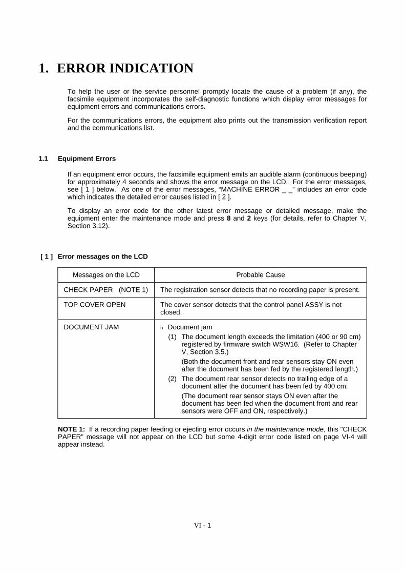
VI - 1
1. ERROR INDICATION
To help the user or the service personnel promptly locate the cause of a problem (if any), thefacsimile equipment incorporates the self-diagnostic functions which display error messages forequipment errors and communications errors.
For the communications errors, the equipment also prints out the transmission verification reportand the communications list.
1.1 Equipment Errors
If an equipment error occurs, the facsimile equipment emits an audible alarm (continuous beeping)for approximately 4 seconds and shows the error message on the LCD. For the error messages,see [ 1 ] below. As one of the error messages, “MACHINE ERROR _ _” includes an error codewhich indicates the detailed error causes listed in [ 2 ].
To display an error code for the other latest error message or detailed message, make theequipment enter the maintenance mode and press 8 and 2 keys (for details, refer to Chapter V,Section 3.12).
[ 1 ] Error messages on the LCD
Messages on the LCD Probable Cause
CHECK PAPER (NOTE 1) The registration sensor detects that no recording paper is present.
TOP COVER OPEN The cover sensor detects that the control panel ASSY is notclosed.
DOCUMENT JAM n Document jam(1) The document length exceeds the limitation (400 or 90 cm)
registered by firmware switch WSW16. (Refer to ChapterV, Section 3.5.)(Both the document front and rear sensors stay ON evenafter the document has been fed by the registered length.)
(2) The document rear sensor detects no trailing edge of adocument after the document has been fed by 400 cm.(The document rear sensor stays ON even after thedocument has been fed when the document front and rearsensors were OFF and ON, respectively.)
NOTE 1: If a recording paper feeding or ejecting error occurs in the maintenance mode, this "CHECKPAPER" message will not appear on the LCD but some 4-digit error code listed on page VI-4 willappear instead.

VI - 2
Messages on the LCD Probable Cause
DOCUMENT JAM n Document loading error(1) The document rear sensor detects no leading edge of a
document within 10 seconds from the start of documentloading operation.(The document rear sensor stays OFF even after thedocument has been fed when the document front sensorwas ON.)
(2) The loaded document is too short.(Since the document is shorter than the distance betweenthe document front and rear sensors, the document frontsensor is turned OFF before the document rear sensor isturned ON.)
CLEAN UP SCANNER In the scanning compensation data list printed by themaintenance-mode function code 05, less than fifty percent of thewhite level data is faulty.
(This message may appear only in the maintenance mode.)
SCANNER ERROR In the scanning compensation data list printed by themaintenance-mode function code 05, fifty percent or more of thewhite level data is faulty.
(This message may appear only in the maintenance mode.)
PRINTER FAULT The thermistor in the recording head caused a heat error.
CHANGE CARTRIDGE The ribbon sensor detects that no ink ribbon is loaded.
MACHINE ERROR _ _orMACHINE ERR _ _ _ _
"_ _" indicates an error code. Refer to Section [ 2 ] on thefollowing pages.
PC BUSY OR FAIL After connected with the host computer, the equipment hasreceived no response from the computer. (A communicationserror has occurred.)
If only an alarm beep is heard without any message on the LCD when the equipment is poweredup, the ROM or RAM will be defective.
VI - 3
[ 2 ] Error codes shown in the "MACHINE ERROR _ _" message
Error Code(Hex.) Error factor
( 85 Ink ribbon empty. )
( 87 Fails to complete the sequence of recording operation. )
8A Wrong or weak contact of the recording head connectors.
( 8B Recording head overheat. )
( A1 Control panel ASSY opened. )
( A2 Document too long to scan. )
( A4 50% or more faulty of white level data. ) *
( A5 Faulty operation of DMA0 during scanning. )
( A6 Faulty operation of DMA1 during scanning. )
( A7 One-line feeding time-out error. )
( A8 One-line scanning time-out error. )
( AB Document feed-in amount measuring error. ) *
( AC Less than 50% faulty of white level data. ) *
( B9 Light emission intensity error of the LED array. )
( BE Abnormal clamp PWM value )
( BF Light emission intensity error of the LED array at the setting time of initial values. ) *
( D5 The MODEM fails to complete the command transmission sequence. )
( D6 No MODEM interrupt for 60 seconds. )
E6 Write error in EEPROM.
( E8 Data scanning error during transmission. )
F3 Voice message recording or playing-back not started.
( F5 EOL not found in page memory transmission mode. )
( F6 PC interface error. )
Error codes in parentheses do not appear in the "MACHINE ERROR _ _," since those errors are displayed asmessages described in "[ 1 ] Error messages on the LCD." You can display those error codes in themaintenance mode (Function code 82). If an equipment error occurs during communications, they appear inthe communications error lists.
*These codes marked with an asterisk can appear only in the maintenance mode.

VI - 4
Error Code(Hex.)
Error factor
( 82xx Although recording paper has been fed by 150 mm after the start of recording, theregistration sensor is still OFF. )
( 8303 Although recording paper has been fed by 360 mm after the start of recording, theregistration sensor is still ON. )
( 8809 Before the start of paper feeding, the registration sensor is already ON. )
( 880B The registration sensor is ON when you turn the power on or after you open andclose the control panel ASSY.
( A301 In document scanning, the document front sensor goes OFF although the documentrear sensor is still OFF. )
( A302 In document scanning, the document rear sensor is still OFF although a documenthas passed through the document front sensor. )
( A303 In document ejecting caused by any of the following, the document front sensor goesOFF but the document rear sensor remains OFF:
- Depression of the STOP key in midway of scanning.
- Illegal copying (Copying a document longer than the recording paper or making anenlargement copy larger than the recording paper).
- Recovery operation from the error state (e.g., "DOCUMENT JAM" and "CHECKPAPER" error.)
( A304 In document ejecting caused by any of the following, the document rear sensor sticksto OFF:
- Depression of the STOP key in midway of scanning.
- Illegal copying (Copying a document longer than the recording paper or making anenlargement copy larger than the recording paper).
- Recovery operation from the error state (e.g., "DOCUMENT JAM" and "CHECKPAPER" error.)
( A307 In document scanning, the document rear sensor remains ON although the documenthas been fed by the specified amount after the document front sensor went OFF. )
( A308 In document ejecting caused by any of the following, the document rear sensorremains ON although the document has been fed by the specified amount after thedocument front sensor went OFF:
- Depression of the STOP key in midway of scanning.
- Illegal copying (Copying a document longer than the recording paper or making anenlargement copy larger than the recording paper).
- Recovery operation from the error state (e.g., "DOCUMENT JAM" and "CHECKPAPER" error.)
NOTE: Four-digit error codes listed above are preceded by MACHINE ERR instead of MACHINEERROR.Error codes in parentheses do not appear in the "MACHINE ERR _ _ _ _," since those errors are displayed asmessages described in "[ 1 ] Error messages on the LCD." You can display those error codes in themaintenance mode (Function code 82). If an equipment error occurs during communications, they appear inthe communications error lists.

VI - 5
1.2 Communications Errors
If a communications error occurs, the facsimile equipment
emits an audible alarm (intermittent beeping) for approximately 4 seconds,
displays the corresponding error message, and
prints out the transmission verification report if the equipment is in sending operation.

VI - 6
nn Definition of Error Codes on the Communications List
(1) Calling
Code 1 Code 2 Causes
10 08 Wrong number called.
11 01 No dial tone detected before start of dialing.
11 02 Busy tone detected before dialing.
11 03 2nd dial tone not detected.
11 05 No loop current detected.*
11 06 Busy tone detected after dialing or called.
11 07 No response from the remote station in sending.
11 10 No tone detected after dialing.
17 07 No response from the calling station in receiving.
* Available in Germany and Austria only.
(2) Command reception
Code 1 Code 2 Causes
20 01 Unable to detect a flag field.
20 02 Carrier was OFF for 200 ms or longer.
20 03 Abort detected ("1" in succession for 7 bits or more).
20 04 Overrun detected.
20 05 A frame for 3 seconds or more received.
20 06 CRC error in answerback.
20 07 Undefined command received.
20 08 Invalid command received.
20 09 Command ignored once for document setting or for dumping-outat turn-around transmission.
20 0A T5 time-out error
20 0B CRP received.
20 0C EOR and NULL received.

VI - 7
(3) Compatibility [checking the NSF and DIS]
Code 1 Code 2 Causes
32 01 Remote terminal only with V.29 capability in 2400 or 4800 bpstransmission.
32 02 Remote terminal not ready for polling.
32 10 Remote terminal not equipped with password function or itspassword switch OFF.
32 11 Remote terminal not equipped with or not ready for confidentialmail box function.
32 12 Remote terminal not equipped with or not ready for relaybroadcasting function.
32 13 No confidential mail in the remote terminal.
32 14 The available memory space of the remote terminal is less thanthat required for reception of the confidential or relay broadcastinginstruction.
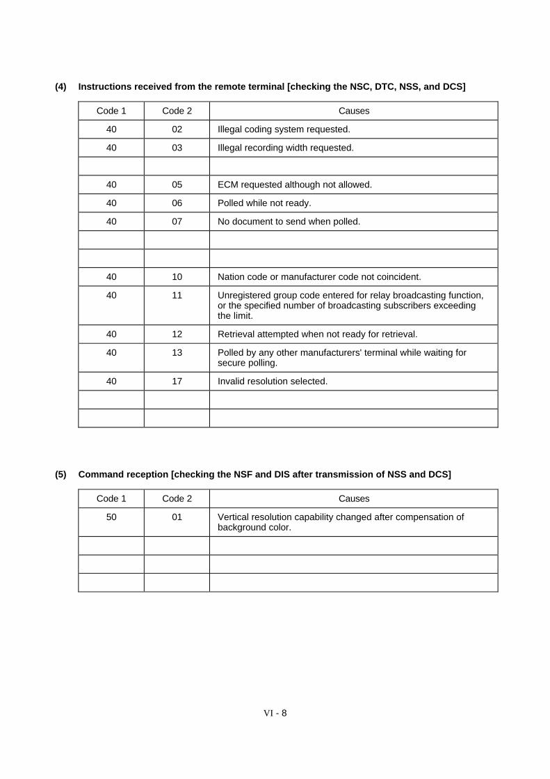
VI - 8
(4) Instructions received from the remote terminal [checking the NSC, DTC, NSS, and DCS]
Code 1 Code 2 Causes
40 02 Illegal coding system requested.
40 03 Illegal recording width requested.
40 05 ECM requested although not allowed.
40 06 Polled while not ready.
40 07 No document to send when polled.
40 10 Nation code or manufacturer code not coincident.
40 11 Unregistered group code entered for relay broadcasting function,or the specified number of broadcasting subscribers exceedingthe limit.
40 12 Retrieval attempted when not ready for retrieval.
40 13 Polled by any other manufacturers' terminal while waiting forsecure polling.
40 17 Invalid resolution selected.
(5) Command reception [checking the NSF and DIS after transmission of NSS and DCS]
Code 1 Code 2 Causes
50 01 Vertical resolution capability changed after compensation ofbackground color.

VI - 9
(6) ID checking
Code 1 Code 2 Causes
63 01 Password plus "lower 4 digits of telephone number" notcoincident.
63 02 Password not coincident.
63 03 Polling ID not coincident.
63 04 Entered confidential mail box ID uncoincident with the mail boxID.
63 05 Relay broadcasting ID not coincident.
63 06 Entered retrieval ID uncoincident with that of the mail box ID.
(7) DCN reception
Code 1 Code 2 Causes
74 DCN received.
(8) TCF transmission/reception
Code 1 Code 2 Causes
80 01 Fallback impossible.
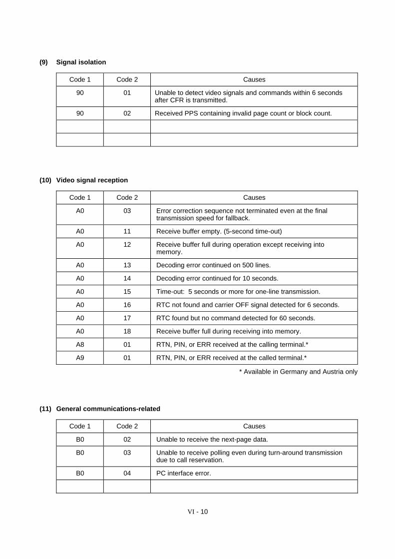
VI - 10
(9) Signal isolation
Code 1 Code 2 Causes
90 01 Unable to detect video signals and commands within 6 secondsafter CFR is transmitted.
90 02 Received PPS containing invalid page count or block count.
(10) Video signal reception
Code 1 Code 2 Causes
A0 03 Error correction sequence not terminated even at the finaltransmission speed for fallback.
A0 11 Receive buffer empty. (5-second time-out)
A0 12 Receive buffer full during operation except receiving intomemory.
A0 13 Decoding error continued on 500 lines.
A0 14 Decoding error continued for 10 seconds.
A0 15 Time-out: 5 seconds or more for one-line transmission.
A0 16 RTC not found and carrier OFF signal detected for 6 seconds.
A0 17 RTC found but no command detected for 60 seconds.
A0 18 Receive buffer full during receiving into memory.
A8 01 RTN, PIN, or ERR received at the calling terminal.*
A9 01 RTN, PIN, or ERR received at the called terminal.*
* Available in Germany and Austria only
(11) General communications-related
Code 1 Code 2 Causes
B0 02 Unable to receive the next-page data.
B0 03 Unable to receive polling even during turn-around transmissiondue to call reservation.
B0 04 PC interface error.

VI - 11
(12) Maintenance mode
Code 1 Code 2 Causes
E0 01 Failed to detect 1300 Hz signal in burn-in operation.
E0 02 Failed to detect PB signals in burn-in operation.
E0 03 Failed to detect any command from the RS-232C interface inburn-in operation.
(13) Equipment error
Code 1 Code 2 Causes
FF X X Equipment error (For X X, refer to Subsection 1.1 [ 2 ].)
VI - 12
2. TROUBLESHOOTING2.1 Introduction
This section gives the service personnel some of the troubleshooting procedures to be followed ifan error or malfunction occurs with the facsimile equipment. It is impossible to anticipate all of thepossible problems which may occur in future and determine the troubleshooting procedures, sothis section covers some sample problems. However, those samples will help service personnelpinpoint and repair other defective elements if he/she analyzes and examines them well.
2.2 Precautions
Be sure to observe the following to prevent the secondary troubles from happening:
(1) Always unplug the AC power cord from the outlet when removing the covers and PCBs,adjusting the mechanisms, or conducting continuity testing with a circuit tester.
(2) When disconnecting the connectors, do not pull the lead wires but hold the connectorhousings.
(3) Before handling the PCBs, touch a metal portion of the machine to discharge static electricitycharged in your body.
When repairing the PCBs, handle them with extra care.
After repairing the defective section, be sure to check again if the repaired section works correctly.Also record the troubleshooting procedure so that it would be of use for future trouble occurrence.
2.3 Checking prior to Troubleshooting
Prior to proceeding to the troubleshooting procedures given in Subsection 2.4, check that :
(1) Each voltage level on AC input lines and DC lines is correct.
(2) All cables and harnesses are firmly connected.
(3) None of the fuses are blown.

VI - 13
2.4 Troubleshooting Procedures
[ 1 ] Control panel related
Trouble Check:
(1) LCD shows nothing. • Panel-main harness between the main PCB and the controlPCB
• Interfaces between the main PCB, NCU PCB and power supplyPCB
• LCD
• Control panel PCB
• Power supply PCB
• NCU PCB
• Main PCB
(2) Control panel inoperative. • Panel-main harness between the main PCB and the controlPCB
• Interfaces between the main PCB, NCU PCB and power supplyPCB
• Control panel PCB
• FPC key
• Main PCB
[ 2 ] Telephone related
Trouble Check:
(1) No phone call can be made. • FPC key
• Control panel PCB by using the maintenance-mode functioncode 13. If any defective keys are found, replace them. (Referto Chapter V, Section 3.7, "Operational Check of Control PanelPCB.")
• NCU PCB
• Main PCB
(2) Speed dialing or one-touchdialing will not work.
• Ordinary dialing function (other than the speed and one-touchdialing)If it works normally, check the main PCB; if not, refer to item (1)above.
(3) Speaker silent during on-hookdialing.
• Ordinary dialing function (Pick up the handset and press thenumerical keys.)
If it works normally, proceed to the following checks; if not, referto item (1) above.
(4) Dial does not switch betweentone and pulse.
• Main PCB
(Not supported by the U.S.A. versions.)
(5) Telephone does not ring. • Speaker
• NCU PCB
• Main PCB

VI - 14
[ 3 ] Communications related
Trouble Check:
(1) No tone is transmitted. • Main PCB
• NCU PCB
[ 4 ] Paper/document feeding related
Trouble Check:
(1) Neither "COPY: PRESSCOPY" nor "FAX: NO. &START" message appearsalthough documents are set.
• Sensors by using the maintenance-mode function code 32.(Refer to Chapter V, Section 3.8, "Sensor Operational Check".)
• Document front sensor actuator and rear sensor actuator
• Control panel PCB and its harness
• Main PCB
(2) Document not fed. • ADF and its related sections
• Drive motor and its harness
• LF roller and its related gears
• Arm HP switch and the planetary gear train
• Main PCB
(3) Recording paper not fed. • ACF and its related sections
• Drive motor and its harness
• Platen and its related gears
• Arm HP switch and the planetary gear train
• Sensor PCB and its harness
• Main PCB
(4) Document double feeding • ADF parts
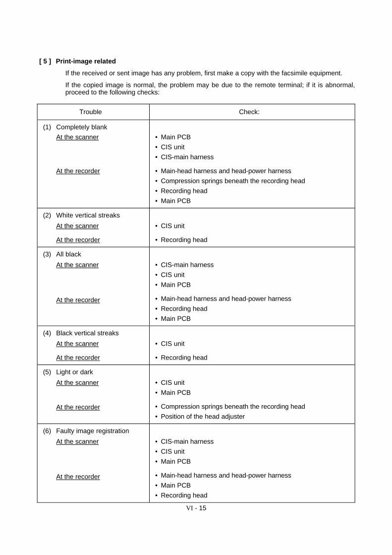
VI - 15
[ 5 ] Print-image related
If the received or sent image has any problem, first make a copy with the facsimile equipment.
If the copied image is normal, the problem may be due to the remote terminal; if it is abnormal,proceed to the following checks:
Trouble Check:
(1) Completely blank
At the scanner
At the recorder
• Main PCB
• CIS unit
• CIS-main harness
• Main-head harness and head-power harness
• Compression springs beneath the recording head
• Recording head
• Main PCB
(2) White vertical streaks
At the scanner
At the recorder
• CIS unit
• Recording head
(3) All black
At the scanner
At the recorder
• CIS-main harness
• CIS unit
• Main PCB
• Main-head harness and head-power harness
• Recording head
• Main PCB
(4) Black vertical streaks
At the scanner
At the recorder
• CIS unit
• Recording head
(5) Light or dark
At the scanner
At the recorder
• CIS unit
• Main PCB
• Compression springs beneath the recording head
• Position of the head adjuster
(6) Faulty image registration
At the scanner
At the recorder
• CIS-main harness
• CIS unit
• Main PCB
• Main-head harness and head-power harness
• Main PCB
• Recording head
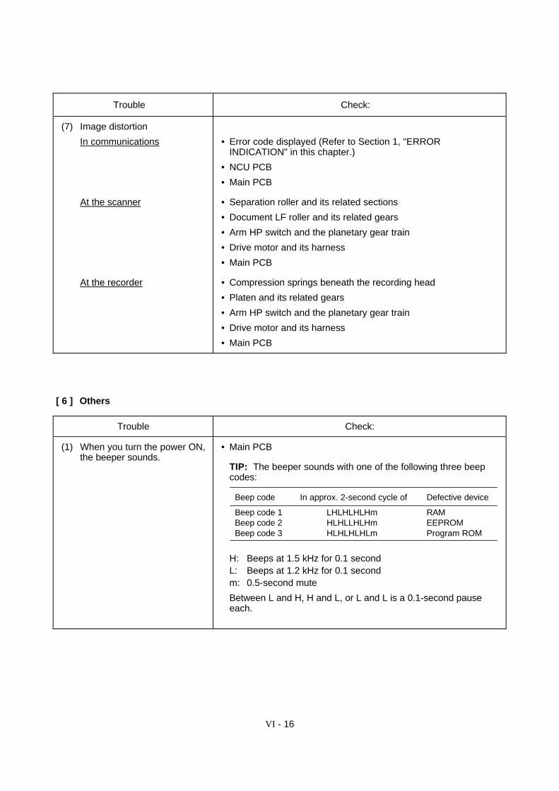
VI - 16
Trouble Check:
(7) Image distortion
In communications
At the scanner
At the recorder
• Error code displayed (Refer to Section 1, "ERRORINDICATION" in this chapter.)
• NCU PCB
• Main PCB
• Separation roller and its related sections
• Document LF roller and its related gears
• Arm HP switch and the planetary gear train
• Drive motor and its harness
• Main PCB
• Compression springs beneath the recording head
• Platen and its related gears
• Arm HP switch and the planetary gear train
• Drive motor and its harness
• Main PCB
[ 6 ] Others
Trouble Check:
(1) When you turn the power ON,the beeper sounds.
• Main PCB
TIP: The beeper sounds with one of the following three beepcodes:
Beep code In approx. 2-second cycle of Defective device
Beep code 1 LHLHLHLHm RAMBeep code 2 HLHLLHLHm EEPROMBeep code 3 HLHLHLHLm Program ROM
H: Beeps at 1.5 kHz for 0.1 secondL: Beeps at 1.2 kHz for 0.1 secondm: 0.5-second mute
Between L and H, H and L, or L and L is a 0.1-second pauseeach.

FAX560/FAX580MC/MFC660MCFAX-T72/FAX-T74/FAX-T76
Appendix 1. EEPROM Customizing Codes

EEPROM Customizing Codes
This function allows you to customize the EEPROM according to language, function settings, andfirmware switch settings. The customizing codes list is given on the next page.
n Operating Procedure
Within 2 seconds
(1) American models: Press the Function, *, 2, 8, 6, and 4 keys in this order to make theequipment enter the maintenance mode.
Within 2 seconds
European models: Press the Menu, *, 2, 8, 6, and 4 keys in this order to make the equipmententer the maintenance mode.
The equipment beeps for approx. one second and displays " " onthe LCD.
(2) Press the 7 and 4 keys in this order in the initial stage of the maintenance mode.
The current customizing code (e.g., 9001 in the case of FAX560 U.S.A. versions) appears.
(3) Enter the desired customizing code (e.g., 0002 in the case of FAX580MC Canadian versions).
The newly entered code appears.
NOTE: If a wrong 4-digit code is entered, the equipment will malfunction.
(4) Press the Start key.
The equipment saves the setting and returns to the initial stage of the maintenance mode.
If you press the Stop key or no keys are pressed for one minute in the above procedure, theequipment stops the procedure and returns to the initial stage of the maintenance mode.
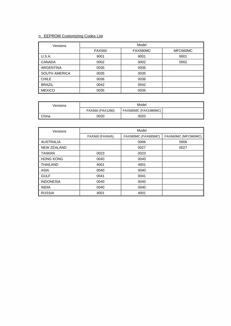
n EEPROM Customizing Codes List
Versions Model
FAX560 FAX580MC MFC660MC
U.S.A. 9001 9001 9001
CANADA 0002 0002 0002
ARGENTINA 0035 0035
SOUTH AMERICA 0035 0035
CHILE 0036 0036
BRAZIL 0042 0042
MEXICO 0035 0035
Versions Model
FAX560 (FAX1280) FAX580MC (FAX1980MC)
China 0020 0020
Versions Model
FAX560 (FAX645) FAX580MC (FAX685MC) FAX660MC (MFC960MC)
AUSTRALIA 0006 0006
NEW ZEALAND 0027 0027
TAIWAN 0023 0023
HONG KONG 0040 0040
THAILAND 4001 4001
ASIA 0040 0040
GULF 0041 0041
INDONESIA 0040 0040
INDIA 0040 0040
RUSSIA 4001 4001
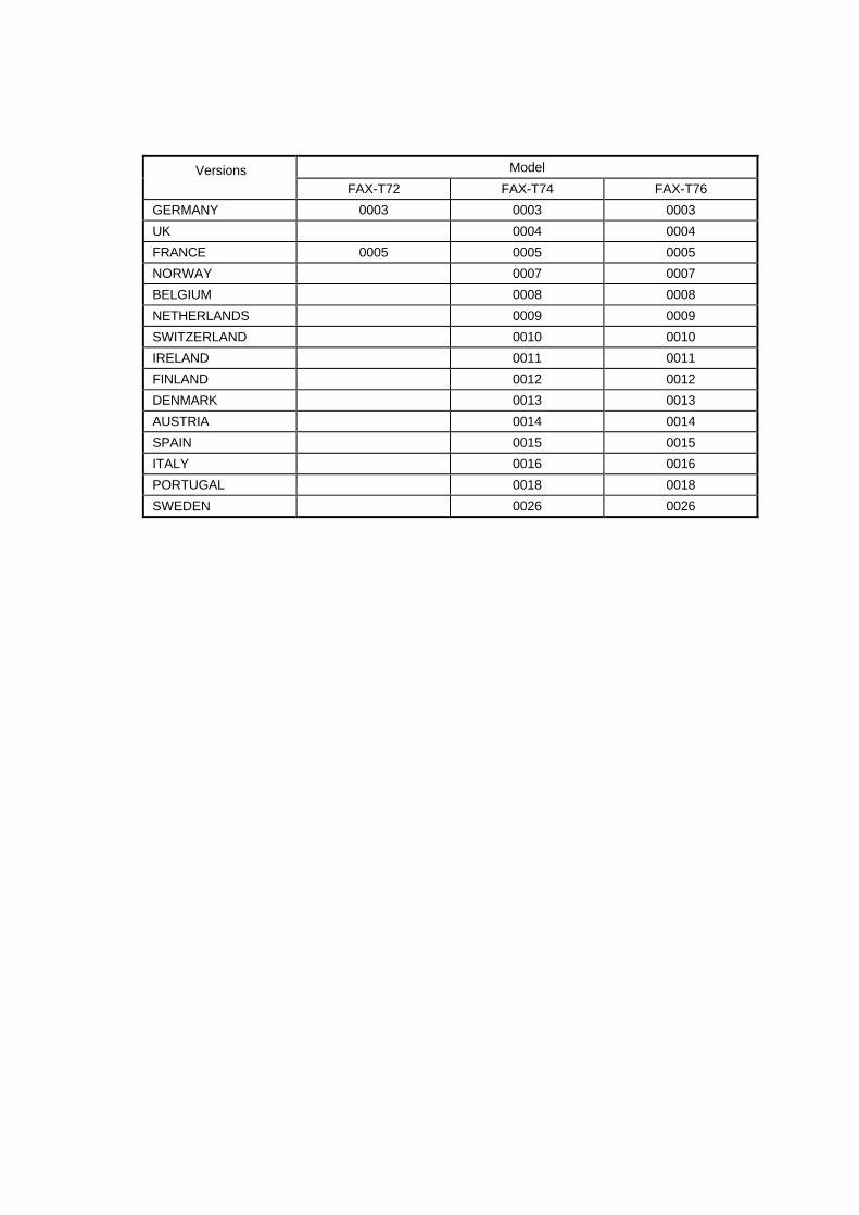
Versions Model
FAX-T72 FAX-T74 FAX-T76
GERMANY 0003 0003 0003
UK 0004 0004
FRANCE 0005 0005 0005
NORWAY 0007 0007
BELGIUM 0008 0008
NETHERLANDS 0009 0009
SWITZERLAND 0010 0010
IRELAND 0011 0011
FINLAND 0012 0012
DENMARK 0013 0013
AUSTRIA 0014 0014
SPAIN 0015 0015
ITALY 0016 0016
PORTUGAL 0018 0018
SWEDEN 0026 0026

FAX560/FAX580MC/MFC660MCFAX-T72/FAX-T74/FAX-T76
Appendix 2. Circuit Diagrams
A. Main PCB
B. Network Control Unit (NCU) PCB
C. Control Panel PCB
D. Power Supply PCB

AMain PCB 1/4(FAX560)
Ceramic capacitorNot mounted
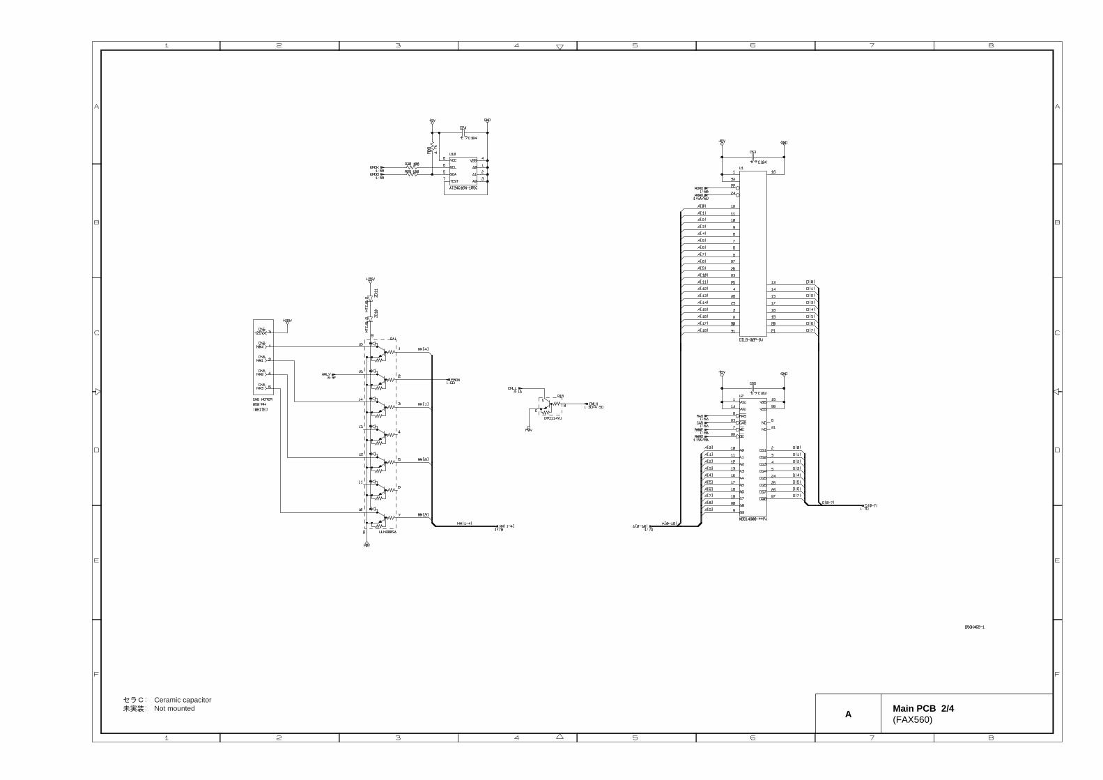
A Main PCB 2/4(FAX560)
Ceramic capacitorNot mounted

A Main PCB 3/4(FAX560)
Ceramic capacitorNot mounted
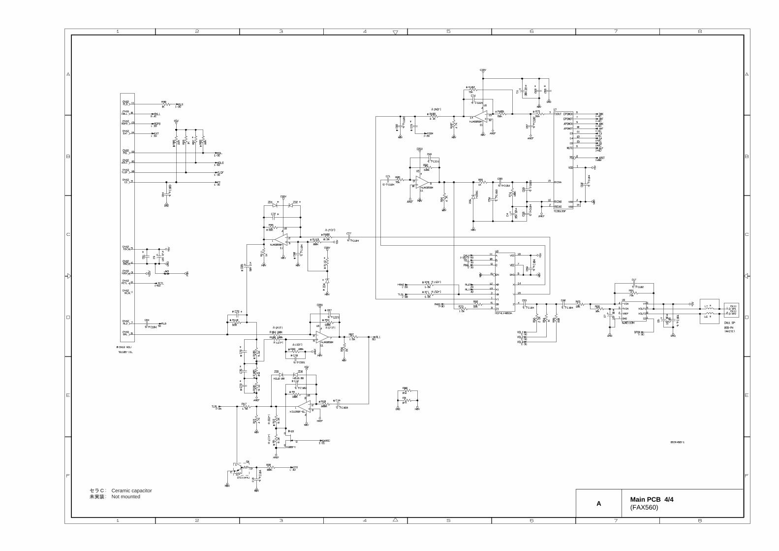
A Main PCB 4/4(FAX560)
Ceramic capacitorNot mounted

AMain PCB 1/4(FAX580MC/MFC660MC)
Ceramic capacitorNot mounted

AMain PCB 2/4(FAX580MC/MFC660MC)
Ceramic capacitorNot mounted

AMain PCB 3/4(FAX580MC/MFC660MC)
Ceramic capacitorNot mounted

AMain PCB 4/4(FAX580MC/MFC660MC)
Ceramic capacitorNot mounted

5
4
S0 V
61
4
3
4
3
+ 2 5 V
CR1A5 X- 2 4 E- 9 0 4
o rOUAZ- SH- 1 2 4 DZ
FG4 2
5 3
4
3
1
2
PL S
S0 V
+
-
2
1 4
3 S0 V
2 1
43TEL OFF
4
5
S0 V
SRL
S0 V
+ 8 V
RL 2
CI
TEL OFF
CML
S0 V
FG
+ 5 V
3 . COMPONENTS I N PARENTHESI S NOT TO BE MOUNTED.
PL S
J UMPER W IRE
P29 1 1 0 S- 0 3 L
S0 V
+ 2 5 V
GNDOUTI N
C5CC1 0 4
C4CC1 0 4
L 2 , L 5SBT0 2 6 0o r FL 5 R2 0 0 PNo r SBT- 0 4 6 0o r DL - 6 5 0 3 C
JW1 + 2 5 V
S0 V
C1
SBT0 2 6 0o r FL 5 R2 0 0 PNo r SBT- 0 4 6 0o r DL - 6 5 0 3 Co r J UMPER W IRE
J W6
J W4
2
+ 2 5 V
S0 V
J W5
5 2 0 6 5 - 6 2 4 5o r 5 2 8 3 0 - 6 2 4 5o r 2 9 0 A- 6 2 - 3 1o r R4 1 - 4 9 1 0 - Ao r 2 8 5 D- D6 2 0 J - 1 1 1o r MJ- 6 2 J - RD3 1 5X2
D1
KI A7 8 0 5 P/PI / AP/ API
o r AN7 8 0 5o r L 7 8 0 5 CV
2 . 0 V X2
4 . DB1 , R3 AND PC1 ARE NOT MOUNTED FOR US MODEL .5 . ZD1 AND ZD2 ARE MOUNTED ONL Y FOR MC MODEL .
A
B
1 2 3
C
D
1 2 3 5 6
A
B
C
D
6
4
4 5
B NCU PCB(U.S./CANADA)

C Control Panel PCB 1/2(FAX560/FAX-T72/FAX-T74)
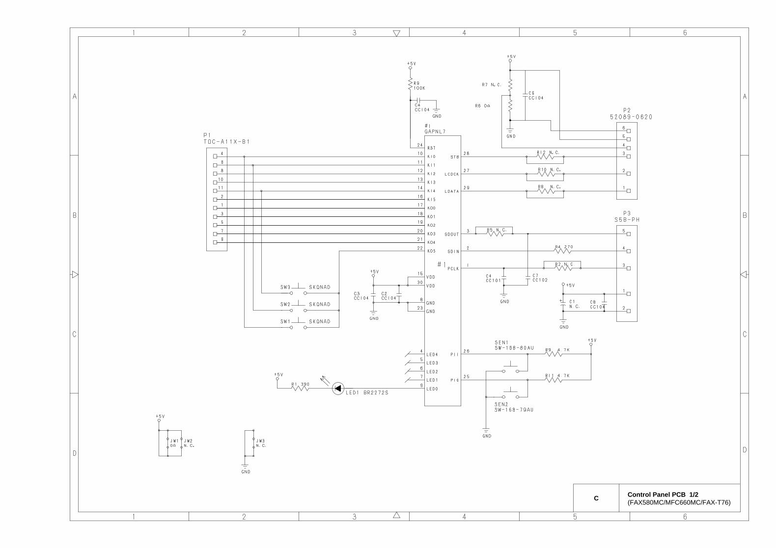
C Control Panel PCB 1/2(FAX580MC/MFC660MC/FAX-T76)
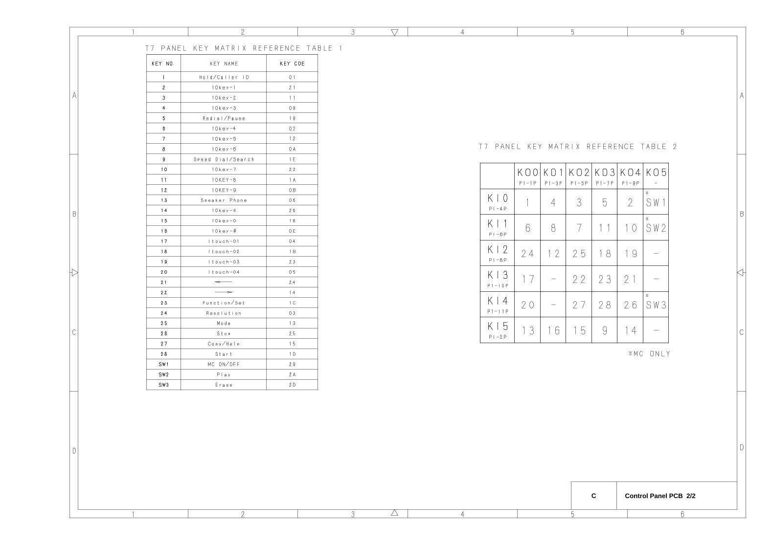
C Control Panel PCB 2/2
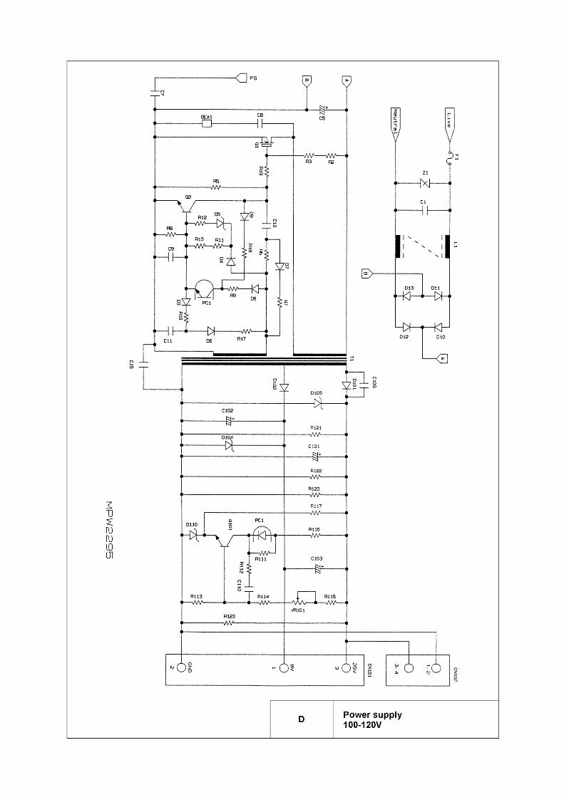

May 20008X4501Printed in Japan