16 obdg03 tcm summary tables t76 (6 speed common)
TRANSCRIPT

Component/ Fault Monitor Strategy Secondary MilSystem Code Description Malfunction Illum.
Transmission Control Module(TCM) C1251 The lateral accleration signal is stuck
at a high magnitude in range Lateral accleration magnitude <= 3.85 g's SpecialNo MIL
Lateral accleration magnitude >= 0.53 g'sLateral accleration magnitude is
within the range above for >= 120 Sec
Lateral accleration magnitude <= 3.85 g'sLateral accleration magnitude >= 0.53 g'sLateral accleration magnitude
is within the range above for >= 90 Sec
Diagnostic shifting overridecommand = FALSE Boolean
Attained Gear State =1st
through6th
Attained Gear Slip <= 100 RPM
Transmission Type =
Clutch toClutch
Transmission
High Side Driver 1 On = TRUE BooleanVehicle Speed >= 15 kph
Lateral acceleration stuck inrange diagnostic enable = TRUE Boolean
Battery Voltage <= 31.999023 VoltsBattery Voltage >= 9 Volts
Battery voltage is within theallowable limits for >= 0.1 Sec
Ignition Voltage <= 31.999023 VoltsIgnition Voltage >= 9 Volts
Service Fast Learn (SFL)Mode = FALSE Boolean
Ignition voltage and SFLconditions met for >= 0.1 Sec
DisableConditions:
MIL not Illuminated forDTC's:
Transmission Control Module(TCM) P0601 Transmission Electro-Hydraulic
Control Module Read Only MemoryIncorrect program/calibrations
checksum = TRUE Boolean >= 5 Fail Counts One Trip
DisableConditions:
MIL not Illuminated forDTC's:
Transmission Control Module(TCM) P0603
Transmission Electro-HydraulicControl Module Long-Term MemoryReset
Non-volatile memory (static ordynamic) checksum failure at
Powerup= TRUE Boolean Runs
Continously
One Trip
Malfunction Threshold Enable TimeCriteria Value Conditions Required
TCM: If calibrated to illuminate the MIL(P0716, P0717, P0721, P0722, P0723,P07BF, P07C0, P077B, P077C, P077D,P215C, U0073)
ECM: None
TCM: P0601
ECM: None
16 OBDG03 TCM Summary Tables T76 (6 Speed Common)
TCM T76 (6 Speed Common) Section 1 of 56 1 of 269
Component/ Fault Monitor Strategy Secondary MilSystem Code Description Malfunction Illum.
Malfunction Threshold Enable TimeCriteria Value Conditions Required
DisableConditions:
MIL not Illuminated forDTC's:
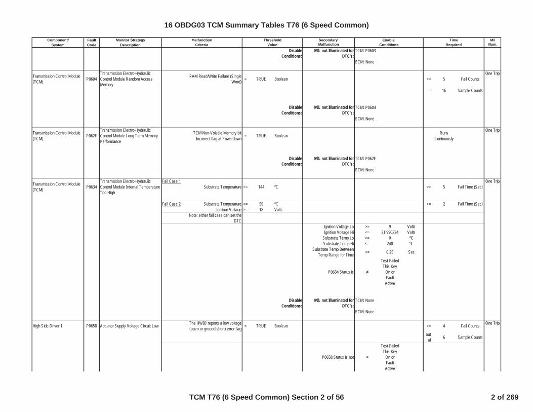
Transmission Control Module(TCM) P0604
Transmission Electro-HydraulicControl Module Random AccessMemory
RAM Read/Write Failure (SingleWord) = TRUE Boolean >= 5 Fail Counts
One Trip
= 16 Sample Counts
DisableConditions:
MIL not Illuminated forDTC's:
Transmission Control Module(TCM) P062F
Transmission Electro-HydraulicControl Module Long Term MemoryPerformance
TCM Non-Volatile Memory bitIncorrect flag at Powerdown = TRUE Boolean Runs
Continously
One Trip
DisableConditions:
MIL not Illuminated forDTC's:
Transmission Control Module(TCM) P0634
Transmission Electro-HydraulicControl Module Internal TemperatureToo High
Fail Case 1Substrate Temperature >= 144 ºC >= 5 Fail Time (Sec)
One Trip
Fail Case 2 Substrate Temperature >= 50 ºC >= 2 Fail Time (Sec)Ignition Voltage >= 18 Volts
Note: either fail case can set theDTC
Ignition Voltage Lo >= 9 VoltsIgnition Voltage Hi <= 31.990234 Volts
Substrate Temp Lo >= 0 ºCSubstrate Temp Hi <= 240 ºC
Substrate Temp BetweenTemp Range for Time >= 0.25 Sec
P0634 Status is
Test FailedThis Key
On orFaultActive
DisableConditions:
MIL not Illuminated forDTC's:
High Side Driver 1 P0658 Actuator Supply Voltage Circuit Low The HWIO reports a low voltage(open or ground short) error flag = TRUE Boolean >= 4 Fail Counts One Trip
outof 6 Sample Counts
P0658 Status is not =
Test FailedThis Key
On orFaultActive
TCM: P0603
ECM: None
TCM: P0604
ECM: None
TCM: P062F
ECM: None
TCM: None
ECM: None
16 OBDG03 TCM Summary Tables T76 (6 Speed Common)
TCM T76 (6 Speed Common) Section 2 of 56 2 of 269
Component/ Fault Monitor Strategy Secondary MilSystem Code Description Malfunction Illum.
Malfunction Threshold Enable TimeCriteria Value Conditions Required
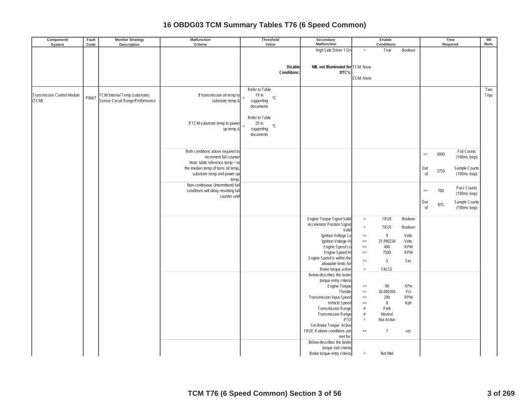
High Side Driver 1 On = True Boolean
DisableConditions:
MIL not Illuminated forDTC's:
Transmission Control Module(TCM) P0667 TCM Internal Temp (substrate)
Sensor Circuit Range/PerformanceIf transmission oil temp to
substrate temp >
Refer to Table19 in
supportingdocuments
ºC
TwoTrips
If TCM substrate temp to powerup temp >
Refer to Table20 in
supportingdocuments
ºC
Both conditions above required toincrement fail counter >= 3000 Fail Counts
(100ms loop)Note: table reference temp = to
the median temp of trans oil temp,substrate temp and power up
temp.
Outof 3750 Sample Counts
(100ms loop)
Non-continuous (intermittent) failconditions will delay resetting fail
counter until>= 700 Pass Counts
(100ms loop)
Outof 875 Sample Counts
(100ms loop)
Engine Torque Signal Valid = TRUE BooleanAccelerator Position Signal
Valid = TRUE Boolean
Ignition Voltage Lo >= 9 VoltsIgnition Voltage Hi <= 31.990234 VoltsEngine Speed Lo >= 400 RPMEngine Speed Hi <= 7500 RPM
Engine Speed is within theallowable limits for >= 5 Sec
Brake torque active = FALSEBelow describes the brake
torque entry criteriaEngine Torque >= 90 N*m
Throttle >= 30.000305 PctTransmission Input Speed <= 200 RPM
Vehicle Speed <= 8 KphTransmission Range ParkTransmission Range Neutral
PTO = Not ActiveSet Brake Torque Active
TRUE if above conditions aremet for:
>= 7 sec
Below describes the braketorque exit criteria
Brake torque entry criteria = Not Met
TCM: None
ECM: None
16 OBDG03 TCM Summary Tables T76 (6 Speed Common)
TCM T76 (6 Speed Common) Section 3 of 56 3 of 269

Component/ Fault Monitor Strategy Secondary MilSystem Code Description Malfunction Illum.
Malfunction Threshold Enable TimeCriteria Value Conditions Required
Clutch hydraulic pressure
ClutchHydraulicAir Purge
Event
Clutch used to exit braketorque active =
CeTFTD_e_C3_RatlE
nblThe above clutch pressure isgreater than this value for one
loop>= 600 kpa
Set Brake Torque ActiveFALSE if above conditions are
met for:>= 20 Sec
P0667 Status is
Test FailedThis Key
On orFaultActive
DisableConditions:
MIL not Illuminated forDTC's:
Transmission Control Module(TCM) P0668 TCM internal temperature (substrate)
thermistor failed at a low voltge Type of Sensor Used =CeTFTI_e_VoltageInverseP
rop
TwoTrips
If TCM Substrate TemperatureSensor = Direct Proportional and
Temp<= 254 ºC
If TCM Substrate TemperatureSensor = Indirect Proportional and
Temp>= 254 ºC
Either condition above will satisfythe fail conditions >= 60 Fail Timer (Sec)
Ignition Voltage Lo >= 9 VoltsIgnition Voltage Hi <= 31.990234 VoltsEngine Speed Lo >= 400 RPMEngine Speed Hi <= 7500 RPM
Engine Speed is within theallowable limits for >= 5 Sec
P0668 Status is
Test FailedThis Key
On orFaultActive
TCM: P0658, P0668, P0669, P06AD,P06AE, P0716, P0712, P0713, P0717,P0722, P0723, P0962, P0963, P0966,P0967, P0970, P0971, P215C, P2720,P2721, P2729, P2730
ECM: P0101, P0102, P0103, P0106,P0107, P0108, P0171, P0172, P0174,P0175, P0201, P0202, P0203, P0204,P0205, P0206, P0207, P0208, P0300,P0301, P0302, P0303, P0304, P0305,P0306, P0307, P0308, P0401, P042E
16 OBDG03 TCM Summary Tables T76 (6 Speed Common)
TCM T76 (6 Speed Common) Section 4 of 56 4 of 269
Component/ Fault Monitor Strategy Secondary MilSystem Code Description Malfunction Illum.
Malfunction Threshold Enable TimeCriteria Value Conditions Required
DisableConditions:
MIL not Illuminated forDTC's:
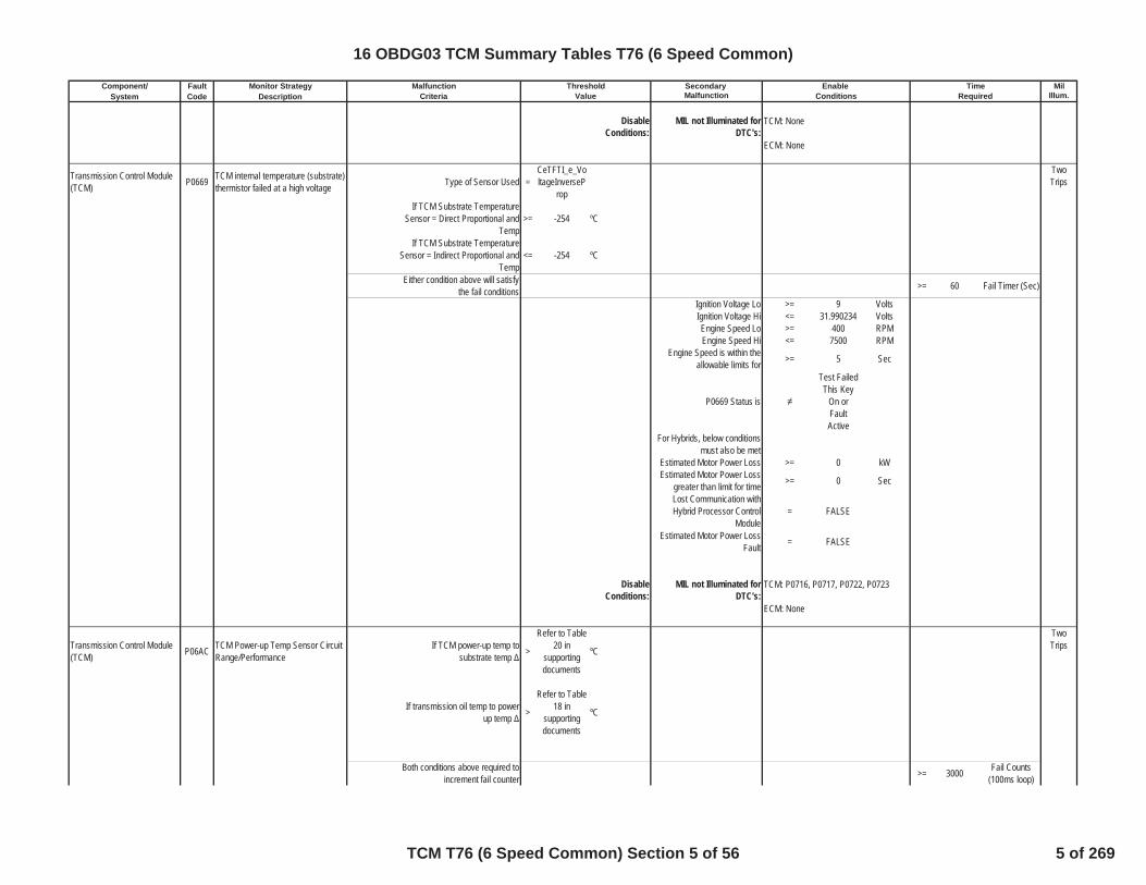
Transmission Control Module(TCM) P0669 TCM internal temperature (substrate)
thermistor failed at a high voltage Type of Sensor Used =CeTFTI_e_VoltageInverseP
rop
TwoTrips
If TCM Substrate TemperatureSensor = Direct Proportional and
Temp>= -254 ºC
If TCM Substrate TemperatureSensor = Indirect Proportional and
Temp<= -254 ºC
Either condition above will satisfythe fail conditions >= 60 Fail Timer (Sec)
Ignition Voltage Lo >= 9 VoltsIgnition Voltage Hi <= 31.990234 VoltsEngine Speed Lo >= 400 RPMEngine Speed Hi <= 7500 RPM
Engine Speed is within theallowable limits for >= 5 Sec
P0669 Status is
Test FailedThis Key
On orFaultActive
For Hybrids, below conditionsmust also be met
Estimated Motor Power Loss >= 0 kWEstimated Motor Power Loss
greater than limit for time >= 0 Sec
Lost Communication withHybrid Processor Control
Module= FALSE
Estimated Motor Power LossFault = FALSE
DisableConditions:
MIL not Illuminated forDTC's:
Transmission Control Module(TCM) P06AC TCM Power-up Temp Sensor Circuit
Range/PerformanceIf TCM power-up temp to
substrate temp >
Refer to Table20 in
supportingdocuments
ºC
TwoTrips
If transmission oil temp to powerup temp >
Refer to Table18 in
supportingdocuments
ºC
Both conditions above required toincrement fail counter >= 3000 Fail Counts
(100ms loop)
TCM: None
ECM: None
TCM: P0716, P0717, P0722, P0723
ECM: None
16 OBDG03 TCM Summary Tables T76 (6 Speed Common)
TCM T76 (6 Speed Common) Section 5 of 56 5 of 269

Component/ Fault Monitor Strategy Secondary MilSystem Code Description Malfunction Illum.
Malfunction Threshold Enable TimeCriteria Value Conditions Required
Note: table reference temp = tothe median temp of trans oil temp,
substrate temp and power uptemp.
Outof 3750 Sample Counts
(100ms loop)
Non-continuous (intermittent) failconditions will delay resetting fail
counter until>= 700 Pass Counts
(100ms loop)
Outof 875 Sample Counts
(100ms loop)
Engine Torque Signal Valid = TRUE BooleanAccelerator Position Signal
Valid = TRUE Boolean
Ignition Voltage Lo >= 9 VoltsIgnition Voltage Hi <= 31.990234 VoltsEngine Speed Lo >= 400 RPMEngine Speed Hi <= 7500 RPM
Engine Speed is within theallowable limits for >= 5 Sec
Brake torque active = FALSEBelow describes the brake
torque entry criteriaEngine Torque >= 90 N*m
Throttle >= 30.000305 PctTransmission Input Speed <= 200 RPM
Vehicle Speed <= 8 KphTransmission Range ParkTransmission Range Neutral
PTO = Not ActiveSet Brake Torque Active
TRUE if above conditions aremet for:
>= 7 sec
Below describes the braketorque exit criteria
Brake torque entry criteria = Not Met
Clutch hydraulic pressure
ClutchHydraulicAir Purge
Event
Clutch used to exit braketorque active =
CeTFTD_e_C3_RatlE
nblThe above clutch pressure isgreater than this value for one
loop>= 600 kpa
Set Brake Torque ActiveFALSE if above conditions are
met for:>= 20 Sec
P06AC Status is
Test FailedThis Key
On orFaultActive
16 OBDG03 TCM Summary Tables T76 (6 Speed Common)
TCM T76 (6 Speed Common) Section 6 of 56 6 of 269
Component/ Fault Monitor Strategy Secondary MilSystem Code Description Malfunction Illum.
Malfunction Threshold Enable TimeCriteria Value Conditions Required
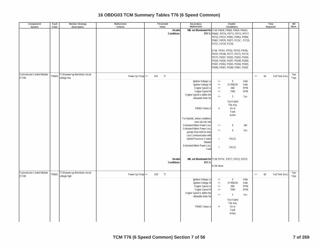
DisableConditions:
MIL not Illuminated forDTC's:
Transmission Control Module(TCM) P06AD TCM power-up thermistor circuit
voltage low Power Up Temp <= 254 ºC >= 60 Fail Time (Sec) TwoTrips
Ignition Voltage Lo >= 9 VoltsIgnition Voltage Hi <= 31.990234 VoltsEngine Speed Lo >= 400 RPMEngine Speed Hi <= 7500 RPM
Engine Speed is within theallowable limits for >= 5 Sec
P06AD Status is
Test FailedThis Key
On orFaultActive
For Hybrids, below conditionsmust also be met
Estimated Motor Power Loss >= 0 kWEstimated Motor Power Loss
greater than limit for time >= 0 Sec
Lost Communication withHybrid Processor Control
Module= FALSE
Estimated Motor Power LossFault = FALSE
DisableConditions:
MIL not Illuminated forDTC's:
Transmission Control Module(TCM) P06AE TCM power-up thermistor circuit
voltage high Power Up Temp >= -254 ºC >= 60 Fail Time (Sec) TwoTrips
Ignition Voltage Lo >= 9 VoltsIgnition Voltage Hi <= 31.990234 VoltsEngine Speed Lo >= 400 RPMEngine Speed Hi <= 7500 RPM
Engine Speed is within theallowable limits for >= 5 Sec
P06AE Status is
Test FailedThis Key
On orFaultActive
TCM: P0716, P0717, P0722, P0723
ECM: None
TCM: P0658, P0668, P0669, P06AD,P06AE, P0716, P0712, P0713, P0717,P0722, P0723, P0962, P0963, P0966,P0967, P0970, P0971, P215C, P2720,P2721, P2729, P2730
ECM: P0101, P0102, P0103, P0106,P0107, P0108, P0171, P0172, P0174,P0175, P0201, P0202, P0203, P0204,P0205, P0206, P0207, P0208, P0300,P0301, P0302, P0303, P0304, P0305,P0306, P0307, P0308, P0401, P042E
16 OBDG03 TCM Summary Tables T76 (6 Speed Common)
TCM T76 (6 Speed Common) Section 7 of 56 7 of 269

Component/ Fault Monitor Strategy Secondary MilSystem Code Description Malfunction Illum.
Malfunction Threshold Enable TimeCriteria Value Conditions Required
DisableConditions:
MIL not Illuminated forDTC's:
Transmission FluidTemperature Sensor (TFT) P0711 Trans Fluid Temp Sensor Circuit
Range/PerformanceIf transmission oil temp to
substrate temp >
Refer to Table19 in
supportingdocuments
ºC
TwoTrips
If transmission oil temp to powerup temp >
Refer to Table18 in
supportingdocuments
ºC
Both conditions above required toincrement fail counter >= 3000 Fail Counts
(100ms loop)Note: table reference temp = to
the median temp of trans oil temp,substrate temp and power up
temp.
Outof 3750 Sample Counts
(100ms loop)
Non-continuous (intermittent) failconditions will delay resetting fail
counter until>= 700 Pass Counts
(100ms loop)
Outof 875 Sample Counts
(100ms loop)
Engine Torque Signal Valid = TRUE BooleanAccelerator Position Signal
Valid = TRUE Boolean
Ignition Voltage Lo >= 9 VoltsIgnition Voltage Hi <= 31.990234 VoltsEngine Speed Lo >= 400 RPMEngine Speed Hi <= 7500 RPM
Engine Speed is within theallowable limits for >= 5 Sec
Brake torque active = FALSEBelow describes the brake
torque entry criteriaEngine Torque >= 90 N*m
Throttle >= 30.000305 PctTransmission Input Speed <= 200 RPM
Vehicle Speed <= 8 KphTransmission Range ParkTransmission Range Neutral
PTO = Not ActiveSet Brake Torque Active
TRUE if above conditions aremet for:
>= 7 sec
Below describes the braketorque exit criteria
Brake torque entry criteria = Not Met
Clutch hydraulic pressure
ClutchHydraulicAir Purge
Event
TCM: None
ECM: None
16 OBDG03 TCM Summary Tables T76 (6 Speed Common)
TCM T76 (6 Speed Common) Section 8 of 56 8 of 269

Component/ Fault Monitor Strategy Secondary MilSystem Code Description Malfunction Illum.
Malfunction Threshold Enable TimeCriteria Value Conditions Required
Clutch used to exit braketorque active =
CeTFTD_e_C3_RatlE
nblThe above clutch pressure isgreater than this value for one
loop>= 600 kpa
Set Brake Torque ActiveFALSE if above conditions are
met for:>= 20 Sec
P0711 Status is
Test FailedThis Key
On orFaultActive
DisableConditions:
MIL not Illuminated forDTC's:
Transmission FluidTemperature Sensor (TFT) P0712 Transmission fluid temperature
thermistor failed at a low voltage Type of Sensor Used =CeTFTI_e_VoltageInverseP
rop
TwoTrips
If Transmission Fluid TemperatureSensor = Direct Proportional and
Temp<= 254 ºC
If Transmission Fluid TemperatureSensor = Indirect Proportional and
Temp>= 254 ºC
Either condition above will satisfythe fail conditions >= 60 Fail Time (Sec)
Ignition Voltage Lo >= 9 VoltsIgnition Voltage Hi <= 31.990234 VoltsEngine Speed Lo >= 400 RPMEngine Speed Hi <= 7500 RPM
Engine Speed is within theallowable limits for >= 5 Sec
P0712 Status is
Test FailedThis Key
On orFaultActive
For Hybrids, below conditionsmust also be met
Estimated Motor Power Loss >= 0 kWEstimated Motor Power Loss
greater than limit for time >= 0 Sec
TCM: P0658, P0668, P0669, P06AD,P06AE, P0716, P0712, P0713, P0717,P0722, P0723, P0962, P0963, P0966,P0967, P0970, P0971, P215C, P2720,P2721, P2729, P2730
ECM: P0101, P0102, P0103, P0106,P0107, P0108, P0171, P0172, P0174,P0175, P0201, P0202, P0203, P0204,P0205, P0206, P0207, P0208, P0300,P0301, P0302, P0303, P0304, P0305,P0306, P0307, P0308, P0401, P042E
16 OBDG03 TCM Summary Tables T76 (6 Speed Common)
TCM T76 (6 Speed Common) Section 9 of 56 9 of 269
Component/ Fault Monitor Strategy Secondary MilSystem Code Description Malfunction Illum.
Malfunction Threshold Enable TimeCriteria Value Conditions Required
Lost Communication withHybrid Processor Control
Module= FALSE
Estimated Motor Power LossFault = FALSE
DisableConditions:
MIL not Illuminated forDTC's:
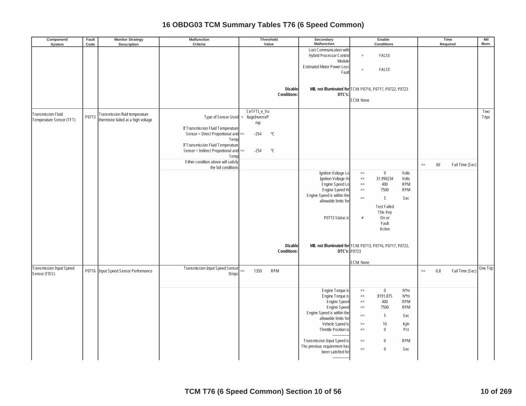
Transmission FluidTemperature Sensor (TFT) P0713 Transmission fluid temperature
thermistor failed at a high voltage Type of Sensor Used =CeTFTI_e_VoltageInverseP
rop
TwoTrips
If Transmission Fluid TemperatureSensor = Direct Proportional and
Temp>= -254 ºC
If Transmission Fluid TemperatureSensor = Indirect Proportional and
Temp<= -254 ºC
Either condition above will satisfythe fail conditions >= 60 Fail Time (Sec)
Ignition Voltage Lo >= 9 VoltsIgnition Voltage Hi <= 31.990234 VoltsEngine Speed Lo >= 400 RPMEngine Speed Hi <= 7500 RPM
Engine Speed is within theallowable limits for >= 5 Sec
P0713 Status is
Test FailedThis Key
On orFaultActive
DisableConditions:
MIL not Illuminated forDTC's:
Transmission Input SpeedSensor (TISS) P0716 Input Speed Sensor Performance Transmission Input Speed Sensor
Drops >= 1350 RPM >= 0.8 Fail Time (Sec) One Trip
Engine Torque is >= 0 N*mEngine Torque is <= 8191.875 N*m
Engine Speed >= 400 RPMEngine Speed <= 7500 RPM
Engine Speed is within theallowable limits for >= 5 Sec
Vehicle Speed is >= 10 KphThrottle Position is >= 0 Pct
--------------Transmission Input Speed is >= 0 RPM
The previous requirement hasbeen satisfied for >= 0 Sec
--------------
TCM: P0716, P0717, P0722, P0723
ECM: None
TCM: P0713, P0716, P0717, P0722,P0723
ECM: None
16 OBDG03 TCM Summary Tables T76 (6 Speed Common)
TCM T76 (6 Speed Common) Section 10 of 56 10 of 269

Component/ Fault Monitor Strategy Secondary MilSystem Code Description Malfunction Illum.
Malfunction Threshold Enable TimeCriteria Value Conditions Required
The change (loop to loop) intransmission input speed is < 8191.75 RPM/Loop
The previous requirement hasbeen satisfied for >= 0 Sec
Throttle Position Signal Valid = TRUE BooleanEngine Torque Signal Valid = TRUE Boolean
Ignition Voltage >= 9 VoltsIgnition Voltage <= 31.990234 Volts
P0716 Status is not =
Test FailedThis Key
On orFaultActive
DisableConditions:
MIL not Illuminated forDTC's:
Transmission Input SpeedSensor (TISS) P0717 Input Speed Sensor Circuit Low
VoltageFail Case 1 Transmission Input Speed is < 33 RPM >= 4.5 Fail Time (Sec) One Trip
Fail Case 2 When P0722 DTC Status equal toTest Failed and Transmission
Input Speed is< 1000 RPM Controller uses a single power
supply for the speed sensors = 1 Boolean
Engine Torque is >= 50 N*mEngine Torque is <= 8191.875 N*m
Vehicle Speed >= 16 KphEngine Torque Signal Valid = TRUE Boolean
Ignition Voltage >= 9 VoltsIgnition Voltage <= 31.990234 Volts
Engine Speed >= 400 RPMEngine Speed <= 7500 RPM
Engine Speed is within theallowable limits for >= 5 Sec
P0717 Status is not =
Test FailedThis Key
On orFaultActive
DisableConditions:
MIL not Illuminated forDTC's:
Transmission Output SpeedSensor (TOSS) P0722 Output Speed Sensor Circuit Low
VoltageTransmission Output Speed
Sensor Raw Speed <= 35 RPM >= 4.5 Fail Time (Sec) One Trip
P0722 Status is not =
Test FailedThis Key
On orFaultActive
Transmission Input SpeedCheck = TRUE Boolean
Engine Torque Check = TRUE Boolean
TCM: P0717, P0752, P0973, P0974
ECM: P0101, P0102, P0103, P0121,P0122, P0123
TCM: P0722, P0723
ECM: P0101, P0102, P0103
16 OBDG03 TCM Summary Tables T76 (6 Speed Common)
TCM T76 (6 Speed Common) Section 11 of 56 11 of 269

Component/ Fault Monitor Strategy Secondary MilSystem Code Description Malfunction Illum.
Malfunction Threshold Enable TimeCriteria Value Conditions Required
Throttle Position >= 8.0001831 PctTransmission Fluid
Temperature >= -40 ºC
Disable this DTC if the PTO isactive = 1 Boolean
Engine Torque Signal Valid = TRUE BooleanThrottle Position Signal Valid = TRUE Boolean
Ignition Voltage is >= 9 VoltsIgnition Voltage is <= 31.990234 Volts
Engine Speed is >= 400 RPMEngine Speed is <= 7500 RPM
Engine Speed is within theallowable limits for >= 5 Sec
Enable_Flags Defined Below
The Engine Torque Check isTRUE, if either of the two
following conditions are TRUE
Engine Torque Condition 1
Range Shift StatusRangeshift
completedENUM
OR
Transmission Range is = Park orNeutral
Engine Torque is >= 8191.75 N*mEngine Torque is <= 8191.75 N*m
Engine Torque Condition 2Engine Torque is >= 30 N*mEngine Torque is <= 8191.75 N*m----------------------
The Transmission Input Speed(TIS) Check is TRUE, if eitherof the two following conditions
are TRUE
TIS Check Condition 1Transmission Input Speed is >= 1000 RPMTransmission Input Speed is <= 8191.75 RPM
TIS Check Condition 2Engine Speed without the
brake applied is >= 3200 RPM
Engine Speed with the brakeapplied is >= 3200 RPM
Engine Speed is <= 8191.75 RPMController uses a single power
supply for the speed sensors = 1 Boolean
Powertrain Brake Pedal isValid = TRUE Boolean
16 OBDG03 TCM Summary Tables T76 (6 Speed Common)
TCM T76 (6 Speed Common) Section 12 of 56 12 of 269

Component/ Fault Monitor Strategy Secondary MilSystem Code Description Malfunction Illum.
Malfunction Threshold Enable TimeCriteria Value Conditions Required
DisableConditions:
MIL not Illuminated forDTC's:
Transmission Output SpeedSensor (TOSS) P0723 Output Speed Sensor Circuit
IntermittentTransmission Output Speed
Sensor Raw Speed >= 105 RPM >= 0 Enable Time(Sec)
One Trip
Output Speed Delta <= 8191.75 RPM >= 0 Enable Time(Sec)
Output Speed Drop > 1000 RPM >= 3Output SpeedDrop RecoveryFail Time (Sec)
AND
Transmission Range is = Driven range(R,D)
----------------------Range_Disable = FALSE See Below
OR----------------------
Neutral_Range_Enable = TRUE See BelowAnd
Neutral_Speed_Enable = TRUE See Beloware TRUE concurrently
----------------------Transmission_Range_Enable = TRUE See Below
Transmission_Input_Speed_Enable = TRUE See Below
No Change in Transfer CaseRange (High <-> Low) for >= 5 Seconds
P0723 Status is not =
Test FailedThis Key
On orFaultActive
Disable this DTC if the PTO isactive = 1 Boolean
Ignition Voltage is >= 9 VoltsIgnition Voltage is <= 31.990234 Volts
Engine Speed is >= 400 RPMEngine Speed is <= 7500 RPM
Engine Speed is within theallowable limits for >= 5 Sec
Enable_Flags Defined Below
Transmission_Input_Speed_Enable is TRUE when either TISCondition 1 or TIS Condition 2
is TRUE:
TIS Condition 1 is TRUE whenboth of the following conditions
are satsified for>= 0 Enable Time
(Sec)
Input Speed Delta <= 4095 RPMRaw Input Speed >= 500 RPM
TCM: P0716, P0717, P0723
ECM: P0101, P0102, P0103, P0121,P0122, P0123
16 OBDG03 TCM Summary Tables T76 (6 Speed Common)
TCM T76 (6 Speed Common) Section 13 of 56 13 of 269

Component/ Fault Monitor Strategy Secondary MilSystem Code Description Malfunction Illum.
Malfunction Threshold Enable TimeCriteria Value Conditions Required
TIS Condition 2 is TRUE whenALL of the next two conditions
are satisfiedInput Speed = 0 RPM
A Single Power Supply is usedfor all speed sensors = TRUE Boolean
----------------------Neutral_Range_Enable is
TRUE when any of the next 3conditions are TRUE
Transmission Range is = Neutral ENUM
Transmission Range is =Reverse/N
eutralTransitonal
ENUM
Transmission Range is =
Neutral/Drive
Transitional
ENUM
And when a drop occurs
Loop to Loop Drop ofTransmission Output Speed is > 650 RPM
----------------------Range_Disable is TRUE when
any of the next threeconditions are TRUE
Transmission Range is = Park ENUM
Transmission Range is =Park/Reve
rseTransitonal
ENUM
Input Clutch is not = ON (FullyApplied) ENUM
----------------------Neutral_Speed_Enable is
TRUE when All of the nextthree conditions are satsified
for
> 1.5 Seconds
Transmission Output Speed > 130 RPM
The loop to loop change of theTransmission Output Speed is < 125 RPM
The loop to loop change of theTransmission Output Speed is > -10 RPM
----------------------Transmission_Range_Enableis TRUE when one of the next
six conditions is TRUETransmission Range is = Neutral ENUM
Transmission Range is =
Reverse/Neutral
Transitional
ENUM
16 OBDG03 TCM Summary Tables T76 (6 Speed Common)
TCM T76 (6 Speed Common) Section 14 of 56 14 of 269
Component/ Fault Monitor Strategy Secondary MilSystem Code Description Malfunction Illum.
Malfunction Threshold Enable TimeCriteria Value Conditions Required
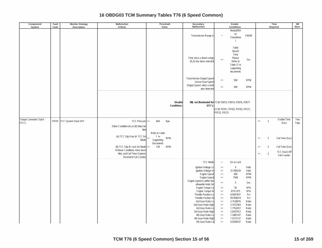
Transmission Range is =
Neutral/Drive
Transitional
ENUM
Time since a driven range(R,D) has been selected >=
TableBasedTime
PleaseRefer to
Table 21 insupportingdocuments
Sec
Transmission Output SpeedSensor Raw Speed >= 500 RPM
Output Speed when a faultwas detected >= 500 RPM
DisableConditions:
MIL not Illuminated forDTC's:
Torque Converter Clutch(TCC) P0741 TCC System Stuck OFF TCC Pressure >= 660 Kpa >= 2 Enable Time
(Sec)TwoTrips
Either Condition (A) or (B) Must beMet
(A) TCC Slip Error @ TCC OnMode >=
Refer to Table1 in
SupportingDocuments
RPM >= 5 Fail Time (Sec)
(B) TCC Slip @ Lock On Mode >= 130 RPM >= 5 Fail Time (Sec)If Above Conditions Have been
Met, and Fail Timer Expired,Increment Fail Counter
>= 2 TCC Stuck OffFail Counter
TCC Mode = On or Lock
Ignition Voltage Lo >= 9 VoltsIgnition Voltage Hi <= 31.990234 Volts
Engine Speed >= 400 RPMEngine Speed <= 7500 RPM
Engine Speed is within theallowable limits for >= 5 Sec
Engine Torque Lo >= 50 N*mEngine Torque Hi <= 8191.875 N*m
Throttle Position Lo >= 8.0001831 PctThrottle Position Hi <= 99.998474 Pct2nd Gear Ratio Lo >= 2.7528076 Ratio
2nd Gear Ratio High <= 3.1672363 Ratio3rd Gear Ratio Lo >= 1.7762451 Ratio
3rd Gear Ratio High <= 2.0437012 Ratio4th Gear Ratio Lo >= 1.3485107 Ratio
4th Gear Ratio High <= 1.5515137 Ratio5th Gear Ratio Lo >= 0.9300537 Ratio
TCM: P0973, P0974, P0976, P0977
ECM: P0101, P0102, P0103, P0121,P0122, P0123
16 OBDG03 TCM Summary Tables T76 (6 Speed Common)
TCM T76 (6 Speed Common) Section 15 of 56 15 of 269

Component/ Fault Monitor Strategy Secondary MilSystem Code Description Malfunction Illum.
Malfunction Threshold Enable TimeCriteria Value Conditions Required
5th Gear Ratio Hi <= 1.0699463 Ratio6th Gear Ratio Lo >= 0.6975098 Ratio
6th Gear Ratio High <= 0.8024902 RatioTransmission Fluid
Temperature Lo >= -6.65625 ºC
Transmission FluidTemperature Hi <= 130 ºC
PTO Not Active = TRUE BooleanEngine Torque Signal Valid = TRUE Boolean
Throttle Position Signal Valid = TRUE BooleanDynamic Mode = FALSE Boolean
P0741 Status is
Test FailedThis Key
On orFaultActive
DisableConditions:
MIL not Illuminated forDTC's:
Torque Converter Clutch(TCC) P0742 TCC System Stuck ON TCC Slip Speed >= -60 RPM One Trip
TCC Slip Speed <= 30 RPM>= 0.4 Fail Time (Sec)
If Above Conditions Have beenMet, and Fail Timer Expired,
Increment Fail Counter>= 5 Fail Counter
TCC Mode = OffEnable test if Cmnd Gear =
1stFW and value true = 1 Boolean
Enable test if Cmnd Gear =2nd and value true = 0 Boolean
Engine Speed Hi <= 6000 RPMEngine Speed Lo >= 500 RPMVehicle Speed HI <= 511 KPHVehicle Speed Lo >= 1 KPHEngine Torque Hi <= 8191.875 NmEngine Torque Lo >= 35 Nm
Current Range Neutral RangeCurrent Range Reverse Range
Transmission SumpTemperature <= 130 ºC
Transmission SumpTemperature >= 15 ºC
Throttle Position Hyst High >= 10.00061 PctAND
Max Vehicle Speed to MeetThrottle Enable <= 8 KPH
TCM: P0716, P0717, P0722, P0723,P0742, P2763, P2764
ECM: P0101, P0102, P0103, P0106,P0107, P0108, P0171, P0172, P0174,P0175, P0201, P0202, P0203, P0204,P0205, P0206, P0207, P0208, P0300,P0301, P0302, P0303, P0304, P0305,P0306, P0307, P0308, P0401, P042E
16 OBDG03 TCM Summary Tables T76 (6 Speed Common)
TCM T76 (6 Speed Common) Section 16 of 56 16 of 269
Component/ Fault Monitor Strategy Secondary MilSystem Code Description Malfunction Illum.
Malfunction Threshold Enable TimeCriteria Value Conditions Required
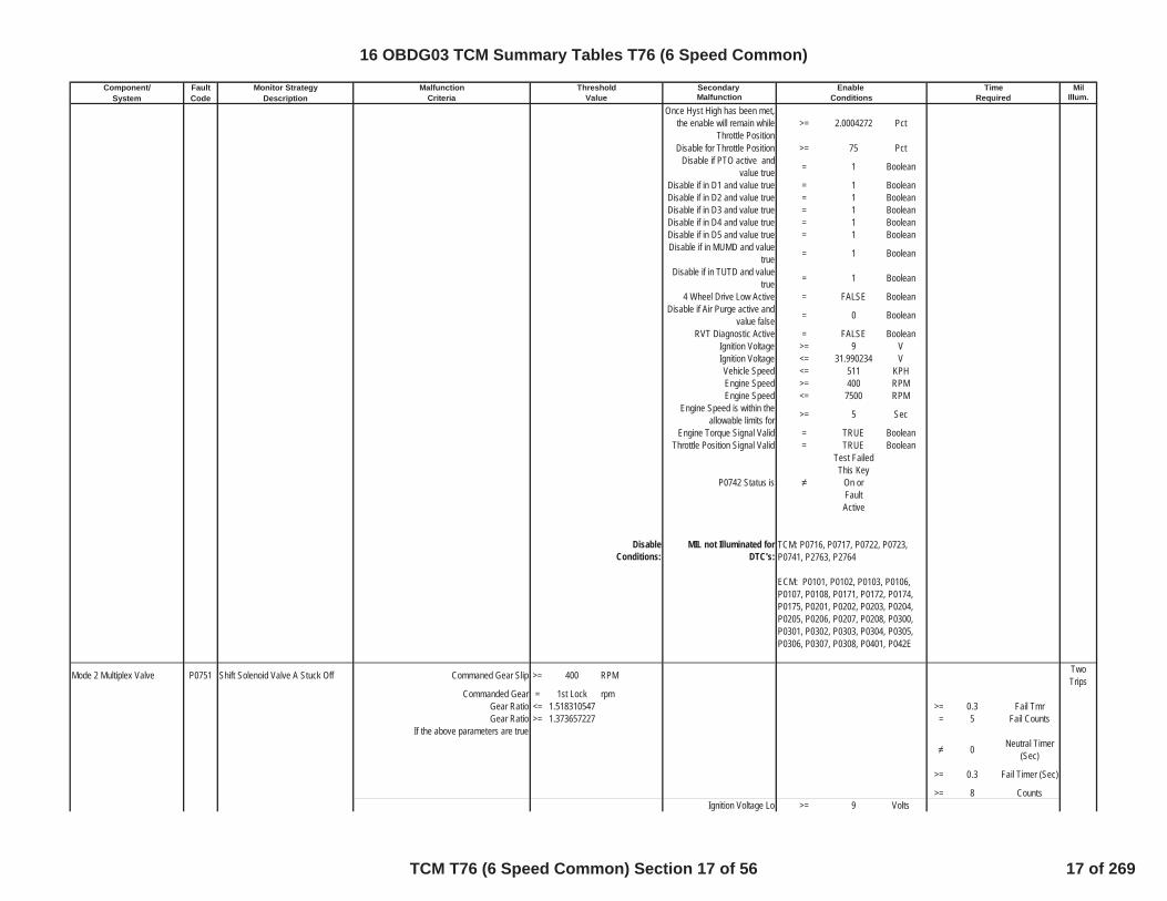
Once Hyst High has been met,the enable will remain while
Throttle Position>= 2.0004272 Pct
Disable for Throttle Position >= 75 PctDisable if PTO active and
value true = 1 Boolean
Disable if in D1 and value true = 1 BooleanDisable if in D2 and value true = 1 BooleanDisable if in D3 and value true = 1 BooleanDisable if in D4 and value true = 1 BooleanDisable if in D5 and value true = 1 BooleanDisable if in MUMD and value
true = 1 Boolean
Disable if in TUTD and valuetrue = 1 Boolean
4 Wheel Drive Low Active = FALSE BooleanDisable if Air Purge active and
value false = 0 Boolean
RVT Diagnostic Active = FALSE BooleanIgnition Voltage >= 9 VIgnition Voltage <= 31.990234 VVehicle Speed <= 511 KPHEngine Speed >= 400 RPMEngine Speed <= 7500 RPM
Engine Speed is within theallowable limits for >= 5 Sec
Engine Torque Signal Valid = TRUE BooleanThrottle Position Signal Valid = TRUE Boolean
P0742 Status is
Test FailedThis Key
On orFaultActive
DisableConditions:
MIL not Illuminated forDTC's:
Mode 2 Multiplex Valve P0751 Shift Solenoid Valve A Stuck Off Commaned Gear Slip >= 400 RPM TwoTrips
Commanded Gear = 1st Lock rpmGear Ratio <= 1.518310547 >= 0.3 Fail TmrGear Ratio >= 1.373657227 = 5 Fail Counts
If the above parameters are true
0 Neutral Timer(Sec)
>= 0.3 Fail Timer (Sec)
>= 8 CountsIgnition Voltage Lo >= 9 Volts
TCM: P0716, P0717, P0722, P0723,P0741, P2763, P2764
ECM: P0101, P0102, P0103, P0106,P0107, P0108, P0171, P0172, P0174,P0175, P0201, P0202, P0203, P0204,P0205, P0206, P0207, P0208, P0300,P0301, P0302, P0303, P0304, P0305,P0306, P0307, P0308, P0401, P042E
16 OBDG03 TCM Summary Tables T76 (6 Speed Common)
TCM T76 (6 Speed Common) Section 17 of 56 17 of 269
Component/ Fault Monitor Strategy Secondary MilSystem Code Description Malfunction Illum.
Malfunction Threshold Enable TimeCriteria Value Conditions Required
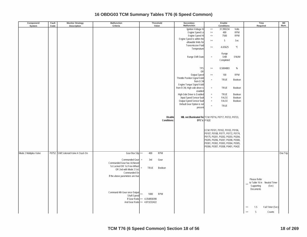
Ignition Voltage Hi <= 31.990234 VoltsEngine Speed Lo >= 400 RPMEngine Speed Hi <= 7500 RPM
Engine Speed is within theallowable limits for >= 5 Sec
Transmission FluidTemperature >= -6.65625 ºC
Range Shift State =RangeShift
CompletedENUM
TPS >= 0.5004883 %OR
Output Speed >= 100 RPMThrottle Position Signal Valid
from ECM = TRUE Boolean
Engine Torque Signal Validfrom ECM, High side driver is
enabled= TRUE Boolean
High-Side Driver is Enabled = TRUE BooleanInput Speed Sensor fault = FALSE Boolean
Output Speed Sensor fault = FALSE BooleanDefault Gear Option is not
present = TRUE
DisableConditions:
MIL not Illuminated forDTC's:
Mode 2 Multiplex Valve P0752 Shift Solenoid Valve A Stuck On Gear Box Slip >= 400 RPM One Trip
Commanded Gear = 3rd GearCommanded Gear has Achieved
1st Locked OR 1st Free-WheelOR 2nd with Mode 2 Sol.
Commanded On
= TRUE Boolean
If the above parameters are true
>=
Please Referto Table 16 in
SupportingDocuments
Neutral Timer(Sec)
Command 4th Gear once OutputShaft Speed <= 1000 RPM
If Gear Ratio >= 4.354858398And Gear Ratio <= 4.813232422
>= 1.5 Fail Timer (Sec)
>= 5 Counts
TCM: P0716, P0717, P0722, P0723,P182E
ECM: P0101, P0102, P0103, P0106,P0107, P0108, P0171, P0172, P0174,P0175, P0201, P0202, P0203, P0204,P0205, P0206, P0207, P0208, P0300,P0301, P0302, P0303, P0304, P0305,P0306, P0307, P0308, P0401, P042E
16 OBDG03 TCM Summary Tables T76 (6 Speed Common)
TCM T76 (6 Speed Common) Section 18 of 56 18 of 269
Component/ Fault Monitor Strategy Secondary MilSystem Code Description Malfunction Illum.
Malfunction Threshold Enable TimeCriteria Value Conditions Required
Ignition Voltage Lo >= 9 VoltsIgnition Voltage Hi <= 31.990234 VoltsEngine Speed Lo >= 400 RPMEngine Speed Hi <= 7500 RPM
Engine Speed is within theallowable limits for >= 5 Sec
High-Side Driver is Enabled = TRUE BooleanThrottle Position Signal Valid
from ECM = TRUE Boolean
Output Speed >= 100 RPMOR
TPS >= 0.5004883 %
Range Shift State =RangeShift
CompletedENUM
Transmission FluidTemperature >= -6.65625 ºC
Input Speed Sensor fault = FALSE BooleanOutput Speed Sensor fault = FALSE BooleanDefault Gear Option is not
present = TRUE
DisableConditions:
MIL not Illuminated forDTC's:
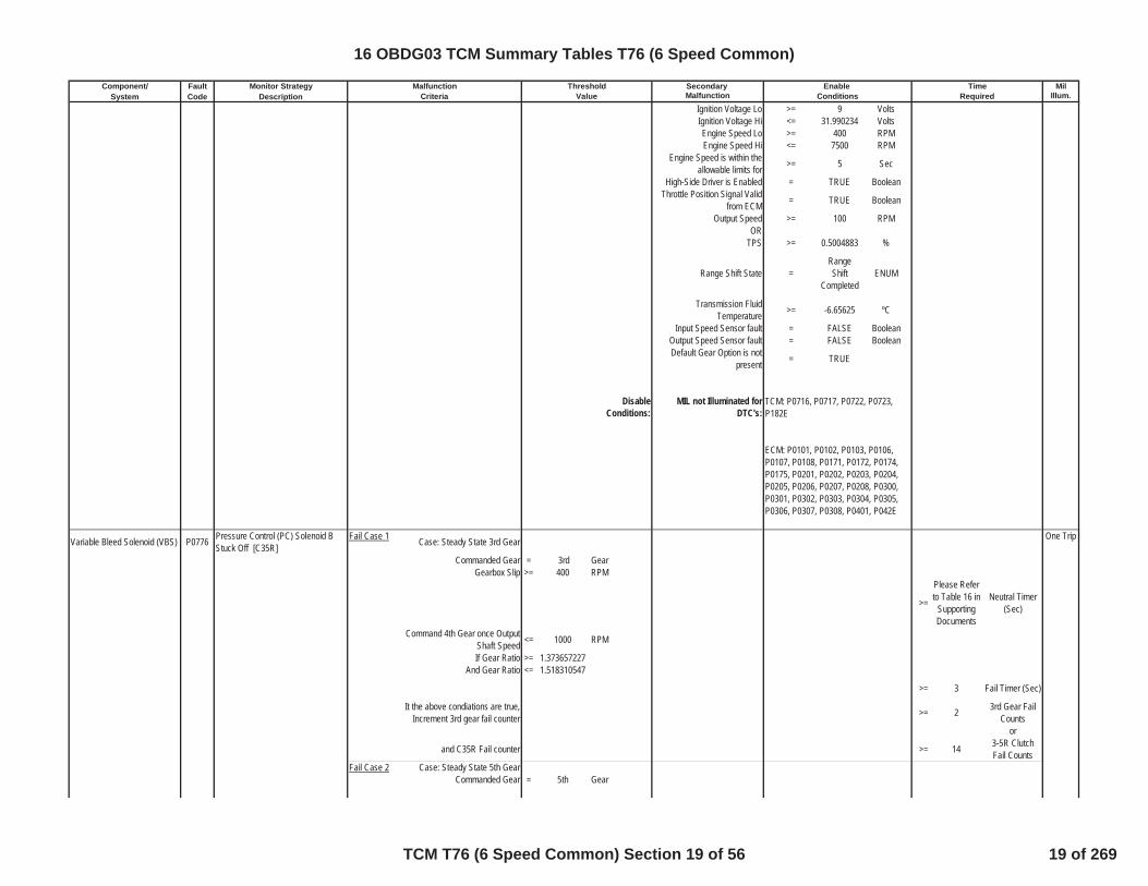
Variable Bleed Solenoid (VBS) P0776 Pressure Control (PC) Solenoid BStuck Off [C35R]
Fail Case 1 Case: Steady State 3rd Gear One Trip
Commanded Gear = 3rd GearGearbox Slip >= 400 RPM
>=
Please Referto Table 16 in
SupportingDocuments
Neutral Timer(Sec)
Command 4th Gear once OutputShaft Speed <= 1000 RPM
If Gear Ratio >= 1.373657227And Gear Ratio <= 1.518310547
>= 3 Fail Timer (Sec)
It the above condiations are true,Increment 3rd gear fail counter >= 2 3rd Gear Fail
Countsor
and C35R Fail counter >= 14 3-5R ClutchFail Counts
Fail Case 2 Case: Steady State 5th GearCommanded Gear = 5th Gear
TCM: P0716, P0717, P0722, P0723,P182E
ECM: P0101, P0102, P0103, P0106,P0107, P0108, P0171, P0172, P0174,P0175, P0201, P0202, P0203, P0204,P0205, P0206, P0207, P0208, P0300,P0301, P0302, P0303, P0304, P0305,P0306, P0307, P0308, P0401, P042E
16 OBDG03 TCM Summary Tables T76 (6 Speed Common)
TCM T76 (6 Speed Common) Section 19 of 56 19 of 269

Component/ Fault Monitor Strategy Secondary MilSystem Code Description Malfunction Illum.
Malfunction Threshold Enable TimeCriteria Value Conditions Required
Gearbox Slip >= 400 Rpm >=
Please Referto Table 5 inSupportingDocuments
Neutral Timer(Sec)
Intrusive Test: Command 6th Gear
If attained Gear=6th gear Time >=
Please referto Table 3 insupportingdocuments
Shift Time (Sec)
It the above condiations are true,Increment 5th gear fail counter >= 3 5th Gear Fail
Countsor
and C35R Fail counter >= 14 3-5R ClutchFail Counts
PRNDL State defaulted = FALSE Booleaninhibit RVT = FALSE Boolean
IMS fault pending indication = FALSE BooleanTPS validity flag = TRUE Boolean
Hydraulic System Pressurized = TRUE BooleanMinimum output speed for
RVT >= 100 RPM
A OR B(A) Output speed enable >= 100 RPM
(B) Accelerator Pedal enable >= 0.5004883 PctCommon Enable Criteria
Ignition Voltage Lo >= 9 VoltsIgnition Voltage Hi <= 31.990234 VoltsEngine Speed Lo >= 400 RPMEngine Speed Hi <= 7500 RPM
Engine Speed is within theallowable limits for >= 5 Sec
Throttle Position Signal valid = TRUE BooleanHSD Enabled = TRUE Boolean
Transmission FluidTemperature >= -6.65625 ºC
Input Speed Sensor fault = FALSE BooleanOutput Speed Sensor fault = FALSE BooleanDefault Gear Option is not
present = TRUE
DisableConditions:
MIL not Illuminated forDTC's:
Variable Bleed Solenoid (VBS) P0777 Pressure Control (PC) Solinoid BStuck On [C35R] (Steady State)
Fail Case 1 Case: Steady State 1st One Trip
Attained Gear slip >= 400 RPM
TCM: P0716, P0717, P0722, P0723,P182E
ECM: P0101, P0102, P0103, P0106,P0107, P0108, P0171, P0172, P0174,P0175, P0201, P0202, P0203, P0204,P0205, P0206, P0207, P0208, P0300,P0301, P0302, P0303, P0304, P0305,P0306, P0307, P0308, P0401, P042E
16 OBDG03 TCM Summary Tables T76 (6 Speed Common)
TCM T76 (6 Speed Common) Section 20 of 56 20 of 269
Component/ Fault Monitor Strategy Secondary MilSystem Code Description Malfunction Illum.
Malfunction Threshold Enable TimeCriteria Value Conditions Required
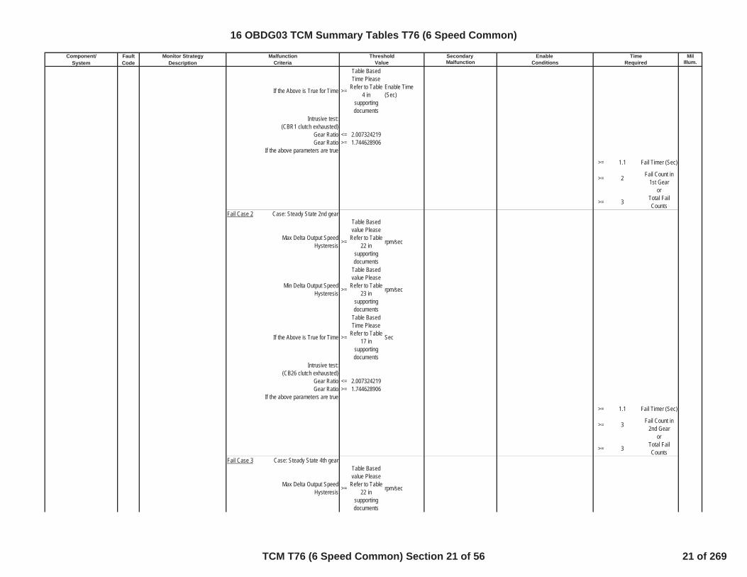
If the Above is True for Time >=
Table BasedTime Please
Refer to Table4 in
supportingdocuments
Enable Time(Sec)
Intrusive test:(CBR1 clutch exhausted)
Gear Ratio <= 2.007324219Gear Ratio >= 1.744628906
If the above parameters are true
>= 1.1 Fail Timer (Sec)
>= 2 Fail Count in1st Gear
or
>= 3 Total FailCounts
Fail Case 2 Case: Steady State 2nd gear
Max Delta Output SpeedHysteresis >=
Table Basedvalue Please
Refer to Table22 in
supportingdocuments
rpm/sec
Min Delta Output SpeedHysteresis >=
Table Basedvalue Please
Refer to Table23 in
supportingdocuments
rpm/sec
If the Above is True for Time >=
Table BasedTime Please
Refer to Table17 in
supportingdocuments
Sec
Intrusive test: (CB26 clutch exhausted)
Gear Ratio <= 2.007324219Gear Ratio >= 1.744628906
If the above parameters are true
>= 1.1 Fail Timer (Sec)
>= 3 Fail Count in2nd Gear
or
>= 3 Total FailCounts
Fail Case 3 Case: Steady State 4th gear
Max Delta Output SpeedHysteresis >=
Table Basedvalue Please
Refer to Table22 in
supportingdocuments
rpm/sec
16 OBDG03 TCM Summary Tables T76 (6 Speed Common)
TCM T76 (6 Speed Common) Section 21 of 56 21 of 269

Component/ Fault Monitor Strategy Secondary MilSystem Code Description Malfunction Illum.
Malfunction Threshold Enable TimeCriteria Value Conditions Required
Min Delta Output SpeedHysteresis >=
Table Basedvalue Please
Refer to Table23 in
supportingdocuments
rpm/sec
If the Above is True for Time >=
Table BasedTime Please
Refer to Table17 in
supportingdocuments
Sec
Intrusive test: (C1234 clutch exhausted)
Gear Ratio <= 1.069946289Gear Ratio >= 0.930053711
If the above parameters are true
>= 1.1 Fail Timer (Sec)
>= 3 Fail Count in4th Gear
or
>= 3 Total FailCounts
Fail Case 4 Case: Steady State 6th gear
Max Delta Output SpeedHysteresis >=
Table Basedvalue Please
Refer to Table22 in
supportingdocuments
rpm/sec
Min Delta Output SpeedHysteresis >=
Table Basedvalue Please
Refer to Table23 in
supportingdocuments
rpm/sec
If the Above is True for Time >=
Table BasedTime Please
Refer to Table17 in
supportingdocuments
Sec
Intrusive test: (CB26 clutch exhausted)
Gear Ratio <= 1.069946289 >= 1.1 Fail Timer (Sec)
Gear Ratio >= 0.930053711 >= 3 countsIf the above parameters are true
>= 1.1 Fail Timer (Sec)
>= 3 Fail Count in6th Gear
or
>= 3 Total FailCounts
PRNDL State defaulted = FALSE Boolean
16 OBDG03 TCM Summary Tables T76 (6 Speed Common)
TCM T76 (6 Speed Common) Section 22 of 56 22 of 269

Component/ Fault Monitor Strategy Secondary MilSystem Code Description Malfunction Illum.
Malfunction Threshold Enable TimeCriteria Value Conditions Required
inhibit RVT = FALSE BooleanIMS fault pending indication = FALSE Boolean
output speed >= 0 RPMTPS validity flag = TRUE Boolean
HSD Enabled = TRUE BooleanHydraulic_System_Pressurize
d = TRUE Boolean
A OR B(A) Output speed enable >= 100 Nm
(B) Accelerator Pedal enable >= 0.5004883 NmIgnition Voltage Lo >= 9 VoltsIgnition Voltage Hi <= 31.990234 VoltsEngine Speed Lo >= 400 RPMEngine Speed Hi <= 7500 RPM
Engine Speed is within theallowable limits for >= 5 Sec
if Attained Gear=1st FWAccelerator Pedal enable >= 10.00061 Pct
if Attained Gear=1st FWEngine Torque Enable >= 45 Nm
if Attained Gear=1st FWEngine Torque Enable <= 8191.875 Nm
Transmission FluidTemperature >= -6.65625 ºC
Input Speed Sensor fault = FALSE BooleanOutput Speed Sensor fault = FALSE Boolean
DisableConditions:
MIL not Illuminated forDTC's:
Variable Bleed Solenoid (VBS) P0777 Pressure Control (PC) Solenoid BStuckOn [C35R] (Dymanic)
Primary Offgoing Clutch isexhausted (See Table 12 in
Supporting Documents forExhaust Delay Timers)
= TRUE Boolean
One Trip
Primary Oncoming ClutchPressure Command Status = Maximum
pressurized
Primary Offgoing Clutch PressureCommand Status =
Clutchexhaust
command
Range Shift Status Initial ClutchControl
Attained Gear Slip <= 50 RPM
If the above conditions are truerun appropriate Fail 1 Timers
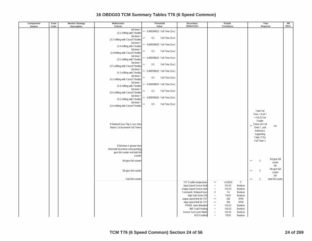
Below:fail timer 1
(3-1 shifting with Closed Throttle) >= 0.5 Fail Time (Sec)
TCM: P0716, P0717, P0722, P0723,P182E
ECM: P0101, P0102, P0103, P0106,P0107, P0108, P0171, P0172, P0174,P0175, P0201, P0202, P0203, P0204,P0205, P0206, P0207, P0208, P0300,P0301, P0302, P0303, P0304, P0305,P0306, P0307, P0308, P0401, P042E
16 OBDG03 TCM Summary Tables T76 (6 Speed Common)
TCM T76 (6 Speed Common) Section 23 of 56 23 of 269
Component/ Fault Monitor Strategy Secondary MilSystem Code Description Malfunction Illum.
Malfunction Threshold Enable TimeCriteria Value Conditions Required
fail timer 1(3-2 shifting with Throttle) >= 0.400390625 Fail Time (Sec)
fail timer 1(3-2 shifting with Closed Throttle) >= 0.5 Fail Time (Sec)
fail timer 1(3-4 shifting with Throttle) >= 0.400390625 Fail Time (Sec)
fail timer 1(3-4shifting with Closed Throttle) >= 0.5 Fail Time (Sec)
fail timer 1(3-5 shifting with Throttle) >= 0.400390625 Fail Time (Sec)
fail timer 1(3-5 shifting with Closed Throttle) >= 0.5 Fail Time (Sec)
fail timer 1(5-3 shifting with Throttle) >= 0.400390625 Fail Time (Sec)
fail timer 1(5-3 shifting with Closed Throttle) >= 0.5 Fail Time (Sec)
fail timer 1(5-4 shifting with Throttle) >= 0.400390625 Fail Time (Sec)
fail timer 1(5-4 shifting with Closed Throttle) >= 0.5 Fail Time (Sec)
fail timer 1(5-6 shifting with Throttle) >= 0.400390625 Fail Time (Sec)
fail timer 1(5-6 shifting with Closed Throttle) >= 0.5 Fail Time (Sec)
If Attained Gear Slip is Less thanAbove Cal Increment Fail Timers >=
Total FailTime = (Fail 1+ Fail 2) See
EnableTimers for FailTimer 1, andReferenceSupportingTable 15 forFail Timer 2
sec
If fail timer is greater thanthreshold increment corresponding
gear fail counter and total failcounter
3rd gear fail counter >= 3 3rd gear failcounts
OR
5th gear fail counter >= 3 5th gear failcounts
ORTotal fail counter >= 3 total fail counts
TUT Enable temperature >= -6.65625 ºCInput Speed Sensor fault = FALSE Boolean
Output Speed Sensor fault = FALSE BooleanCommand / Attained Gear 1st Boolean
High Side Driver ON = TRUE Booleanoutput speed limit for TUT >= 200 RPM
input speed limit for TUT >= 200 RPMPRNDL state defaulted = FALSE Boolean
IMS Fault Pending = FALSE BooleanService Fast Learn Mode = FALSE Boolean
HSD Enabled = TRUE Boolean
16 OBDG03 TCM Summary Tables T76 (6 Speed Common)
TCM T76 (6 Speed Common) Section 24 of 56 24 of 269

Component/ Fault Monitor Strategy Secondary MilSystem Code Description Malfunction Illum.
Malfunction Threshold Enable TimeCriteria Value Conditions Required
Default Gear Option is notpresent = TRUE
DisableConditions:
MIL not Illuminated forDTC's:
Transmission Output SpeedSensor (TOSS) P077C Output Speed Sensor Circuit Low TOSS Analog Signal Voltage <= 0.25 Volts >= 5.00E-02 sec One Trip
P077C Status is not =Test FailedThis Key On
or Fault Active
If the above conditons have beenmet, increment the P077C Fail
CounterDTC P077C Sets when the Fail
Counter >= 75 Counts
P077C Enable Calibration = 1 BooleanIgnition Voltage Lo >= 9 VoltsIgnition Voltage Hi <= 31.990234 Volts
DisableConditions:
MIL not Illuminated forDTC's:
Transmission Output SpeedSensor (TOSS) P077D Output Speed Sensor Circuit High TOSS Analog Signal Voltage >= 4.75 Volts >= 5.00E-02 sec One Trip
P077D Status is not =Test FailedThis Key On
or Fault Active
If the above conditons have beenmet, increment the P077D Fail
CounterDTC P077D Sets when the Fail
Counter >= 75 Counts
P077D Enable Calibration = 1 BooleanIgnition Voltage Lo >= 9 VoltsIgnition Voltage Hi <= 31.990234 Volts
DisableConditions:
MIL not Illuminated forDTC's:
Variable Bleed Solenoid (VBS) P0796 Pressure Control (PC) Solenoid CStuck Off [C456] (Steady State)
Fail Case 1 Case: Steady State 4th Gear One Trip
TCM: P0716, P0717, P0722, P0723,P182E
ECM: P0101, P0102, P0103, P0106,P0107, P0108, P0171, P0172, P0174,P0175, P0201, P0202, P0203, P0204,P0205, P0206, P0207, P0208, P0300,P0301, P0302, P0303, P0304, P0305,P0306, P0307, P0308, P0401, P042E
TCM: P077D
TCM: P077C
16 OBDG03 TCM Summary Tables T76 (6 Speed Common)
TCM T76 (6 Speed Common) Section 25 of 56 25 of 269

Component/ Fault Monitor Strategy Secondary MilSystem Code Description Malfunction Illum.
Malfunction Threshold Enable TimeCriteria Value Conditions Required
Gear slip >= 400 RPM >=
Please SeeTable 5 For
Neutral TimeCal
Neutral Timer(Sec)
Intrusive test:commanded 5th gear
If attained Gear 5th for time >=
Please referto Table 3 inSupportingDocuments
Shift Time (Sec)
if the above conditions have beenmet
Increment 4th Gear Fail Counter >= 2 4th Gear FailCount
OR
and C456 Fail Counters >= 14 C456 FailCounts
Fail Case 2 Case: Steady State 5th Gear
Gear slip >= 400 RPM >=
Please SeeTable 5 For
Neutral TimeCal
Neutral Timer(Sec)
Intrusive test:commanded 6th gear
If attained Gear 6th for time >=
Please Referto Table 3 inSupportingDocuments
Shift Time (Sec)
if the above conditions have beenmet
Increment 5th Gear Fail Counter >= 2 5th Gear FailCount
OR
and C456 Fail Counters >= 14 C456 FailCounts
Fail Case 3 Case: Steady State 6th Gear
Gear slip >= 400 RPM >=
Please SeeTable 5 For
Neutral TimeCal
Neutral Timer(Sec)
Intrusive test:commanded 5th gear
If attained Gear 5th for time >=
Please referto Table 3 inSupportingDocuments
Shift Time (Sec)
if the above conditions have beenmet
Increment 6th Gear Fail Counterand C456 Fail Counter >= 2 6th Gear Fail
CountOR
and C456 Fail Counter >= 14 C456 FailCounts
PRNDL State defaulted = FALSE Booleaninhibit RVT = FALSE Boolean
IMS fault pending indication = FALSE BooleanTPS validity flag = TRUE Boolean
16 OBDG03 TCM Summary Tables T76 (6 Speed Common)
TCM T76 (6 Speed Common) Section 26 of 56 26 of 269

Component/ Fault Monitor Strategy Secondary MilSystem Code Description Malfunction Illum.
Malfunction Threshold Enable TimeCriteria Value Conditions Required
Hydraulic System Pressurized = TRUE BooleanMinimum output speed for
RVT >= 100 RPM
A OR B(A) Output speed enable >= 100 RPM
(B) Accelerator Pedal enable >= 0.5004883 PctCommon Enable Criteria
Ignition Voltage Lo >= 9 VoltsIgnition Voltage Hi <= 31.990234 VoltsEngine Speed Lo >= 400 RPMEngine Speed Hi <= 7500 RPM
Engine Speed is within theallowable limits for >= 5 Sec
Throttle Position Signal valid = TRUE BooleanHSD Enabled = TRUE Boolean
Transmission FluidTemperature >= -6.65625 ºC
Input Speed Sensor fault = FALSE BooleanOutputSpeed Sensor fault = FALSE BooleanDefault Gear Option is not
present = TRUE
DisableConditions:
MIL not Illuminated forDTC's:
Variable Bleed Solenoid (VBS) P0797 Pressure Control (PC) Solenoid CStuck On [C456] (Steady State)
Fail Case 1 Case: Steady State 1st One Trip
Attained Gear slip >= 400 RPM
If the Above is True for Time >=
Table BasedTime Please
Refer to Table4 in
supportingdocuments
Enable Time(Sec)
Intrusive test:(CBR1 clutch exhausted)
Gear Ratio <= 1.529052734Gear Ratio >= 1.328979492
If the above parameters are true
>= 1.1 Fail Timer (Sec)
>= 2 Fail Count in1st Gear
or
>= 3 Total FailCounts
Fail Case 2 Case Steady State 2nd
TCM: P0716, P0717, P0722, P0723,P182E
ECM: P0101, P0102, P0103, P0106,P0107, P0108, P0171, P0172, P0174,P0175, P0201, P0202, P0203, P0204,P0205, P0206, P0207, P0208, P0300,P0301, P0302, P0303, P0304, P0305,P0306, P0307, P0308, P0401, P042E
16 OBDG03 TCM Summary Tables T76 (6 Speed Common)
TCM T76 (6 Speed Common) Section 27 of 56 27 of 269
Component/ Fault Monitor Strategy Secondary MilSystem Code Description Malfunction Illum.
Malfunction Threshold Enable TimeCriteria Value Conditions Required
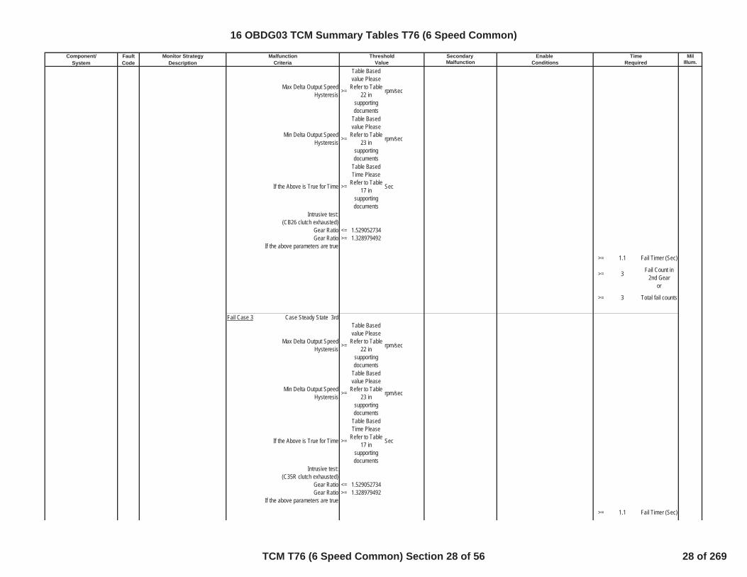
Max Delta Output SpeedHysteresis >=
Table Basedvalue Please
Refer to Table22 in
supportingdocuments
rpm/sec
Min Delta Output SpeedHysteresis >=
Table Basedvalue Please
Refer to Table23 in
supportingdocuments
rpm/sec
If the Above is True for Time >=
Table BasedTime Please
Refer to Table17 in
supportingdocuments
Sec
Intrusive test: (CB26 clutch exhausted)
Gear Ratio <= 1.529052734Gear Ratio >= 1.328979492
If the above parameters are true
>= 1.1 Fail Timer (Sec)
>= 3 Fail Count in2nd Gear
or
>= 3 Total fail counts
Fail Case 3 Case Steady State 3rd
Max Delta Output SpeedHysteresis >=
Table Basedvalue Please
Refer to Table22 in
supportingdocuments
rpm/sec
Min Delta Output SpeedHysteresis >=
Table Basedvalue Please
Refer to Table23 in
supportingdocuments
rpm/sec
If the Above is True for Time >=
Table BasedTime Please
Refer to Table17 in
supportingdocuments
Sec
Intrusive test: (C35R clutch exhausted)
Gear Ratio <= 1.529052734Gear Ratio >= 1.328979492
If the above parameters are true
>= 1.1 Fail Timer (Sec)
16 OBDG03 TCM Summary Tables T76 (6 Speed Common)
TCM T76 (6 Speed Common) Section 28 of 56 28 of 269

Component/ Fault Monitor Strategy Secondary MilSystem Code Description Malfunction Illum.
Malfunction Threshold Enable TimeCriteria Value Conditions Required
>= 3 Fail Count in3rd Gear
OR
>= 3 Total FailCounts
PRNDL State defaulted = FALSE Booleaninhibit RVT = FALSE Boolean
IMS fault pending indication = FALSE Booleanoutput speed >= 0 RPM
TPS validity flag = TRUE BooleanHSD Enabled = TRUE Boolean
Hydraulic_System_Pressurized = TRUE Boolean
A OR B(A) Output speed enable >= 100 Nm
(B) Accelerator Pedal enable >= 0.5004883 NmIgnition Voltage Lo >= 9 VoltsIgnition Voltage Hi <= 31.990234 VoltsEngine Speed Lo >= 400 RPMEngine Speed Hi <= 7500 RPM
Engine Speed is within theallowable limits for >= 5 Sec
if Attained Gear=1st FWAccelerator Pedal enable >= 10.00061 Pct
if Attained Gear=1st FWEngine Torque Enable >= 45 Nm
if Attained Gear=1st FWEngine Torque Enable <= 8191.875 Nm
Transmission FluidTemperature >= -6.65625 ºC
Input Speed Sensor fault = FALSE BooleanOutput Speed Sensor fault = FALSE BooleanDefault Gear Option is not
present = TRUE
DisableConditions:
MIL not Illuminated forDTC's:
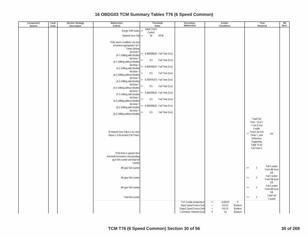
Variable Bleed Solenoid (VBS) P0797 Pressure Control (PC) Solenoid CStuck On [C456] (Dynamic)
Primary Offgoing Clutch isexhausted (See Table 11 in
Supporting Documents forExhaust Delay Timers)
= TRUE Boolean
One Trip
Primary Oncoming ClutchPressure Command Status = Maximum
pressurized
Primary Offgoing Clutch PressureCommand Status =
Clutchexhaust
command
TCM: P0716, P0717, P0722, P0723,P182E
ECM: P0101, P0102, P0103, P0106,P0107, P0108, P0171, P0172, P0174,P0175, P0201, P0202, P0203, P0204,P0205, P0206, P0207, P0208, P0300,P0301, P0302, P0303, P0304, P0305,P0306, P0307, P0308, P0401, P042E
16 OBDG03 TCM Summary Tables T76 (6 Speed Common)
TCM T76 (6 Speed Common) Section 29 of 56 29 of 269
Component/ Fault Monitor Strategy Secondary MilSystem Code Description Malfunction Illum.
Malfunction Threshold Enable TimeCriteria Value Conditions Required
Range Shift Status Initial ClutchControl
Attained Gear Slip <= 50 RPM
If the above conditions are trueincrement appropriate Fail 1
Timers Below:fail timer 1
(4-1 shifting with throttle) >= 0.400390625 Fail Time (Sec)
fail timer 1(4-1 shifting without throttle) >= 0.5 Fail Time (Sec)
fail timer 1(4-2 shifting with throttle) >= 0.400390625 Fail Time (Sec)
fail timer 1(4-2 shifting without throttle) >= 0.5 Fail Time (Sec)
fail timer 1(4-3 shifting with throttle) >= 0.700195313 Fail Time (Sec)
fail timer 1(4-3 shifting without throttle) >= 0.5 Fail Time (Sec)
fail timer 1(5-3 shifting with throttle) >= 0.400390625 Fail Time (Sec)
fail timer 1(5-3 shifting without throttle) >= 0.5 Fail Time (Sec)
fail timer 1(6-2 shifting with throttle) >= 0.400390625 Fail Time (Sec)
fail timer 1(6-2 shifting without throttle) >= 0.5 Fail Time (Sec)
If Attained Gear Slip is Less thanAbove Cal Increment Fail Timers >=
Total FailTime = (Fail 1+ Fail 2) See
EnableTimers for FailTimer 1, andReferenceSupportingTable 15 forFail Timer 2
sec
If fail timer is greater thanthreshold increment corresponding
gear fail counter and total failcounter
4th gear fail counter >= 3 Fail CounterFrom 4th Gear
OR
5th gear fail counter >= 3 Fail CounterFrom 5th Gear
OR
6th gear fail counter >= 3 Fail CounterFrom 6th Gear
OR
Total fail counter >= 3 Total FailCounter
TUT Enable temperature >= -6.65625 ºCInput Speed Sensor fault = FALSE Boolean
Output Speed Sensor fault = FALSE BooleanCommand / Attained Gear 1st Boolean
16 OBDG03 TCM Summary Tables T76 (6 Speed Common)
TCM T76 (6 Speed Common) Section 30 of 56 30 of 269

Component/ Fault Monitor Strategy Secondary MilSystem Code Description Malfunction Illum.
Malfunction Threshold Enable TimeCriteria Value Conditions Required
High Side Driver ON = TRUE Booleanoutput speed limit for TUT >= 200 RPM
input speed limit for TUT >= 200 RPMPRNDL state defaulted = FALSE Boolean
IMS Fault Pending = FALSE BooleanService Fast Learn Mode = FALSE Boolean
HSD Enabled = TRUE Boolean
DisableConditions:
MIL not Illuminated forDTC's:
Transmission Input SpeedSensor (TISS) P07BF Input/Turbine Speed Sensor A
Circuit Low TISS Analog Signal Voltage <= 0.25 Volts >= 5.00E-02 sec One Trip
P07BF Status is not =Test FailedThis Key On
or Fault Active
If the above conditons have beenmet, increment the P07BF Fail
CounterDTC P07BF Sets when the Fail
Counter >= 75 Counts
P07BF Enable Calibration = 1 BooleanIgnition Voltage Lo >= 9 VoltsIgnition Voltage Hi <= 31.990234 Volts
DisableConditions:
MIL not Illuminated forDTC's:
Transmission Input SpeedSensor (TISS) P07C0 Input/Turbine Speed Sensor A
Circuit High TISS Analog Signal Voltage >= 4.75 Volts >= 5.00E-02 sec One Trip
P07C0 Status is not =Test FailedThis Key On
or Fault Active
If the above conditons have beenmet, increment the P07C0 Fail
CounterDTC P07C0 Sets when the Fail
Counter >= 75 Counts
P07C0 Enable Calibration = 1 BooleanIgnition Voltage Lo >= 9 VoltsIgnition Voltage Hi <= 31.990234 Volts
TCM: P0716, P0717, P0722, P0723,P182E
ECM: P0101, P0102, P0103, P0106,P0107, P0108, P0171, P0172, P0174,P0175, P0201, P0202, P0203, P0204,P0205, P0206, P0207, P0208, P0300,P0301, P0302, P0303, P0304, P0305,P0306, P0307, P0308, P0401, P042E
TCM: P07C0
16 OBDG03 TCM Summary Tables T76 (6 Speed Common)
TCM T76 (6 Speed Common) Section 31 of 56 31 of 269
Component/ Fault Monitor Strategy Secondary MilSystem Code Description Malfunction Illum.
Malfunction Threshold Enable TimeCriteria Value Conditions Required
DisableConditions:
MIL not Illuminated forDTC's:
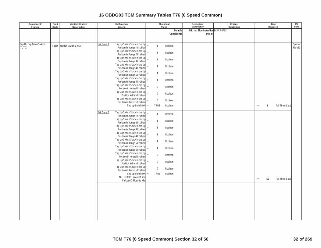
Tap Up Tap Down Switch(TUTD) P0815 Upshift Switch Circuit Fail Case 1 Tap Up Switch Stuck in the Up
Position in Range 1 Enabled = 1 Boolean SpecialNo MIL
Tap Up Switch Stuck in the UpPosition in Range 2 Enabled = 1 Boolean
Tap Up Switch Stuck in the UpPosition in Range 3 Enabled = 1 Boolean
Tap Up Switch Stuck in the UpPosition in Range 4 Enabled = 1 Boolean
Tap Up Switch Stuck in the UpPosition in Range 5 Enabled = 1 Boolean
Tap Up Switch Stuck in the UpPosition in Range 6 Enabled = 1 Boolean
Tap Up Switch Stuck in the UpPosition in Neutral Enabled = 0 Boolean
Tap Up Switch Stuck in the UpPosition in Park Enabled = 0 Boolean
Tap Up Switch Stuck in the UpPosition in Reverse Enabled = 0 Boolean
Tap Up Switch ON = TRUE Boolean >= 1 Fail Time (Sec)
Fail Case 2 Tap Up Switch Stuck in the UpPosition in Range 1 Enabled = 1 Boolean
Tap Up Switch Stuck in the UpPosition in Range 2 Enabled = 1 Boolean
Tap Up Switch Stuck in the UpPosition in Range 3 Enabled = 1 Boolean
Tap Up Switch Stuck in the UpPosition in Range 4 Enabled = 1 Boolean
Tap Up Switch Stuck in the UpPosition in Range 5 Enabled = 1 Boolean
Tap Up Switch Stuck in the UpPosition in Range 6 Enabled = 1 Boolean
Tap Up Switch Stuck in the UpPosition in Neutral Enabled = 0 Boolean
Tap Up Switch Stuck in the UpPosition in Park Enabled = 0 Boolean
Tap Up Switch Stuck in the UpPosition in Reverse Enabled = 0 Boolean
Tap Up Switch ON = TRUE BooleanNOTE: Both Failcase1 and
Failcase 2 Must Be Met >= 120 Fail Time (Sec)
TCM: P07BF
16 OBDG03 TCM Summary Tables T76 (6 Speed Common)
TCM T76 (6 Speed Common) Section 32 of 56 32 of 269

Component/ Fault Monitor Strategy Secondary MilSystem Code Description Malfunction Illum.
Malfunction Threshold Enable TimeCriteria Value Conditions Required
Time Since Last RangeChange >= 1 Enable Time
(Sec)Ignition Voltage Lo >= 9 VoltsIgnition Voltage Hi <= 31.990234 VoltsEngine Speed Lo >= 400 RPMEngine Speed Hi <= 7500 RPM
Engine Speed is within theallowable limits for >= 5 Sec
P0815 Status is
Test FailedThis Key
On orFaultActive
DisableConditions:
MIL not Illuminated forDTC's:
Tap Up Tap Down Switch(TUTD) P0816 Downshift Switch Circuit
Fail Case 1 Tap Down Switch Stuck in theDown Position in Range 1 Enabled = 1 Boolean
SpecialNo MIL
Tap Down Switch Stuck in theDown Position in Range 2 Enabled = 1 Boolean
Tap Down Switch Stuck in theDown Position in Range 3 Enabled = 1 Boolean
Tap Down Switch Stuck in theDown Position in Range 4 Enabled = 1 Boolean
Tap Down Switch Stuck in theDown Position in Range 5 Enabled = 1 Boolean
Tap Down Switch Stuck in theDown Position in Range 6 Enabled = 1 Boolean
Tap Down Switch Stuck in theDown Position in Range Neutral
Enabled= 0 Boolean
Tap Down Switch Stuck in theDown Position in Range Park
Enabled= 0 Boolean
Tap Down Switch Stuck in theDown Position in Range Reverse
Enabled= 0 Boolean
Tap Down Switch ON = TRUE Boolean >= 1 sec
Fail Case 2 Tap Down Switch Stuck in theDown Position in Range 1 Enabled = 1 Boolean
Tap Down Switch Stuck in theDown Position in Range 2 Enabled = 1 Boolean
Tap Down Switch Stuck in theDown Position in Range 3 Enabled = 1 Boolean
TCM: P0816, P0826, P182E, P1876,P1877, P1915, P1761
ECM: None
16 OBDG03 TCM Summary Tables T76 (6 Speed Common)
TCM T76 (6 Speed Common) Section 33 of 56 33 of 269

Component/ Fault Monitor Strategy Secondary MilSystem Code Description Malfunction Illum.
Malfunction Threshold Enable TimeCriteria Value Conditions Required
Tap Down Switch Stuck in theDown Position in Range 4 Enabled = 1 Boolean
Tap Down Switch Stuck in theDown Position in Range 5 Enabled = 1 Boolean
Tap Down Switch Stuck in theDown Position in Range 6 Enabled = 1 Boolean
Tap Down Switch Stuck in theDown Position in Neutral Enabled = 0 Boolean
Tap Down Switch Stuck in theDown Position in Park Enabled = 0 Boolean
Tap Down Switch Stuck in theDown Position in Reverse Enabled = 0 Boolean
Tap Down Switch ON = TRUE BooleanNOTE: Both Failcase1 and
Failcase 2 Must Be Met >= 120 sec
Time Since Last RangeChange >= 1 Enable Time
(Sec)Ignition Voltage Lo >= 9 VoltsIgnition Voltage Hi <= 31.990234 VoltsEngine Speed Lo >= 400 RPMEngine Speed Hi <= 7500 RPM
Engine Speed is within theallowable limits for >= 5 Sec
P0816 Status is
Test FailedThis Key
On orFaultActive
DisableConditions:
MIL not Illuminated forDTC's:
Tap Up Tap Down Switch(TUTD) P0826 Up and Down Shift Switch Circuit TUTD Circuit Reads Invalid
Voltage = TRUE Boolean >= 60 Fail Time (Sec) SpecialNo MIL
Ignition Voltage Lo >= 9 VoltsIgnition Voltage Hi <= 31.990234 VoltsEngine Speed Lo >= 400 RPMEngine Speed Hi <= 7500 RPM
Engine Speed is within theallowable limits for >= 5 Sec
TCM: P0815, P0826, P182E, P1876,P1877, P1915, P1761
ECM: None
16 OBDG03 TCM Summary Tables T76 (6 Speed Common)
TCM T76 (6 Speed Common) Section 34 of 56 34 of 269
Component/ Fault Monitor Strategy Secondary MilSystem Code Description Malfunction Illum.
Malfunction Threshold Enable TimeCriteria Value Conditions Required
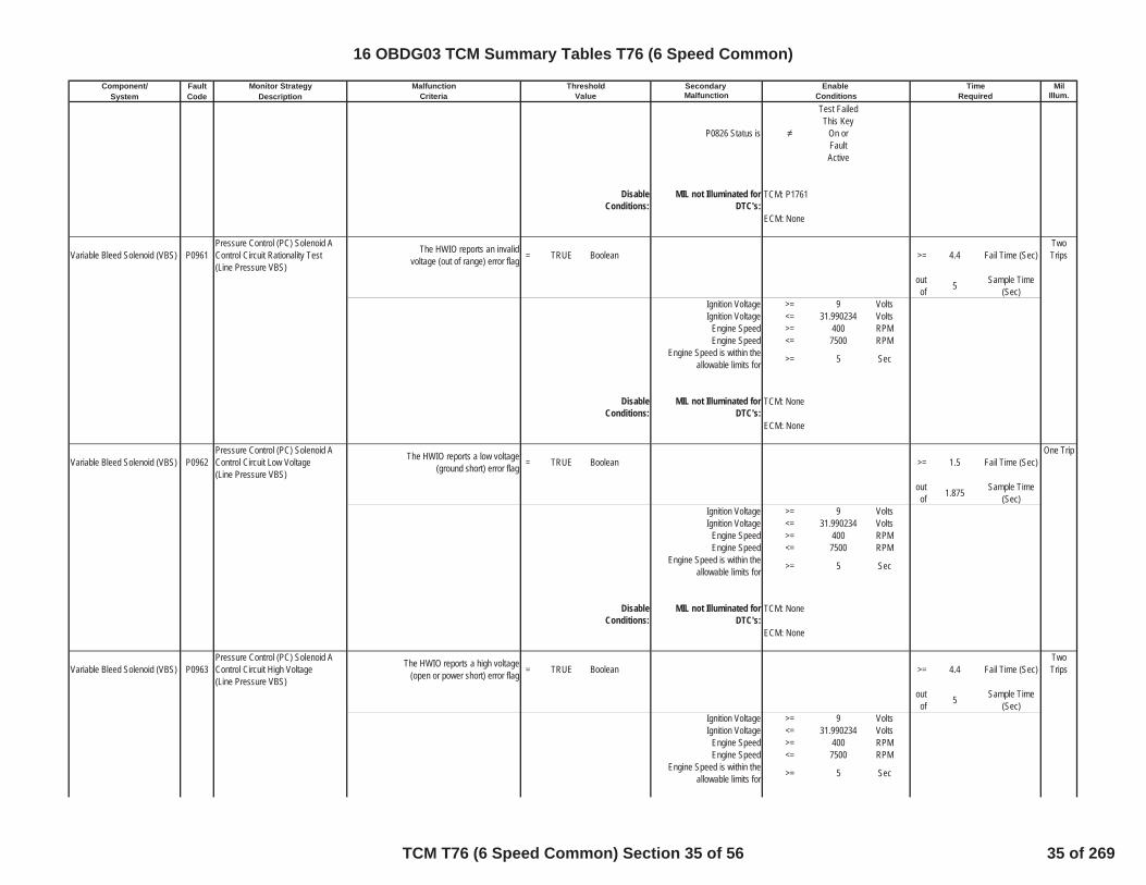
P0826 Status is
Test FailedThis Key
On orFaultActive
DisableConditions:
MIL not Illuminated forDTC's:
Variable Bleed Solenoid (VBS) P0961Pressure Control (PC) Solenoid AControl Circuit Rationality Test(Line Pressure VBS)
The HWIO reports an invalidvoltage (out of range) error flag = TRUE Boolean >= 4.4 Fail Time (Sec)
TwoTrips
outof 5 Sample Time
(Sec)Ignition Voltage >= 9 VoltsIgnition Voltage <= 31.990234 Volts
Engine Speed >= 400 RPMEngine Speed <= 7500 RPM
Engine Speed is within theallowable limits for >= 5 Sec
DisableConditions:
MIL not Illuminated forDTC's:
Variable Bleed Solenoid (VBS) P0962Pressure Control (PC) Solenoid AControl Circuit Low Voltage(Line Pressure VBS)
The HWIO reports a low voltage(ground short) error flag = TRUE Boolean >= 1.5 Fail Time (Sec)
One Trip
outof 1.875 Sample Time
(Sec)Ignition Voltage >= 9 VoltsIgnition Voltage <= 31.990234 Volts
Engine Speed >= 400 RPMEngine Speed <= 7500 RPM
Engine Speed is within theallowable limits for >= 5 Sec
DisableConditions:
MIL not Illuminated forDTC's:
Variable Bleed Solenoid (VBS) P0963Pressure Control (PC) Solenoid AControl Circuit High Voltage(Line Pressure VBS)
The HWIO reports a high voltage(open or power short) error flag = TRUE Boolean >= 4.4 Fail Time (Sec)
TwoTrips
outof 5 Sample Time
(Sec)Ignition Voltage >= 9 VoltsIgnition Voltage <= 31.990234 Volts
Engine Speed >= 400 RPMEngine Speed <= 7500 RPM
Engine Speed is within theallowable limits for >= 5 Sec
TCM: P1761
ECM: None
TCM: None
ECM: None
TCM: None
ECM: None
16 OBDG03 TCM Summary Tables T76 (6 Speed Common)
TCM T76 (6 Speed Common) Section 35 of 56 35 of 269

Component/ Fault Monitor Strategy Secondary MilSystem Code Description Malfunction Illum.
Malfunction Threshold Enable TimeCriteria Value Conditions Required
DisableConditions:
MIL not Illuminated forDTC's:
Variable Bleed Solenoid (VBS) P0966Pressure Control (PC) Solenoid BControl Circuit Low Voltage(C35R VBS)
The HWIO reports a low voltage(ground short) error flag = TRUE Boolean >= 0.3 Fail Time (Sec)
One Trip
outof 0.375 Sample Time
(Sec)Ignition Voltage >= 9 VoltsIgnition Voltage <= 31.990234 Volts
Engine Speed >= 400 RPMEngine Speed <= 7500 RPM
Engine Speed is within theallowable limits for >= 5 Sec
P0966 Status is not =
Test FailedThis Key
On orFaultActive
DisableConditions:
MIL not Illuminated forDTC's:
Variable Bleed Solenoid (VBS) P0967Pressure Control (PC) Solenoid BControl Circuit High Voltage(C35R VBS)
The HWIO reports a high voltage(open or power short) error flag = TRUE Boolean >= 0.3 Fail Time (Sec)
One Trip
outof 0.375 Sample Time
(Sec)Ignition Voltage >= 9 VoltsIgnition Voltage <= 31.990234 Volts
Engine Speed >= 400 RPMEngine Speed <= 7500 RPM
Engine Speed is within theallowable limits for >= 5 Sec
P0967 Status is not =
Test FailedThis Key
On orFaultActive
DisableConditions:
MIL not Illuminated forDTC's:
Variable Bleed Solenoid (VBS) P0970Pressure Control (PC) Solenoid CControl Circuit Low Voltage(C456/CBR1 VBS)
The HWIO reports a low voltage(ground short) error flag = TRUE Boolean >= 0.3 Fail Time (Sec)
One Trip
outof 0.375 Sample Time
(Sec)
TCM: None
ECM: None
TCM: None
ECM: None
TCM: None
ECM: None
16 OBDG03 TCM Summary Tables T76 (6 Speed Common)
TCM T76 (6 Speed Common) Section 36 of 56 36 of 269

Component/ Fault Monitor Strategy Secondary MilSystem Code Description Malfunction Illum.
Malfunction Threshold Enable TimeCriteria Value Conditions Required
P0970 Status is not =
Test FailedThis Key
On orFaultActive
Ignition Voltage >= 9 VoltsIgnition Voltage <= 31.990234 Volts
Engine Speed >= 400 RPMEngine Speed <= 7500 RPM
Engine Speed is within theallowable limits for >= 5 Sec
DisableConditions:
MIL not Illuminated forDTC's:
Variable Bleed Solenoid (VBS) P0971Pressure Control (PC) Solenoid CControl Circuit High Voltage(C456/CBR1 VBS)
The HWIO reports a high voltage(open or power short) error flag = TRUE Boolean >= 0.3 Fail Time (Sec)
One Trip
outof 0.375 Sample Time
(Sec)
P0971 Status is not =
Test FailedThis Key
On orFaultActive
Ignition Voltage >= 9 VoltsIgnition Voltage <= 31.990234 Volts
Engine Speed >= 400 RPMEngine Speed <= 7500 RPM
Engine Speed is within theallowable limits for >= 5 Sec
DisableConditions:
MIL not Illuminated forDTC's:
Shift Solinoid P0973 Shift Solenoid A Control Circuit Low(Mode 2 Solenoid)
The HWIO reports a low voltage(ground short) error flag = TRUE Boolean >= 1.2 Fail Time (Sec) One Trip
outof 1.5 Sample Time
(Sec)
P0973 Status is not =
Test FailedThis Key
On orFaultActive
Ignition Voltage >= 9 VoltsIgnition Voltage <= 31.990234 Volts
Engine Speed >= 400 RPMEngine Speed <= 7500 RPM
Engine Speed is within theallowable limits for >= 5 Sec
TCM: None
ECM: None
TCM: None
ECM: None
16 OBDG03 TCM Summary Tables T76 (6 Speed Common)
TCM T76 (6 Speed Common) Section 37 of 56 37 of 269
Component/ Fault Monitor Strategy Secondary MilSystem Code Description Malfunction Illum.
Malfunction Threshold Enable TimeCriteria Value Conditions Required
DisableConditions:
MIL not Illuminated forDTC's:
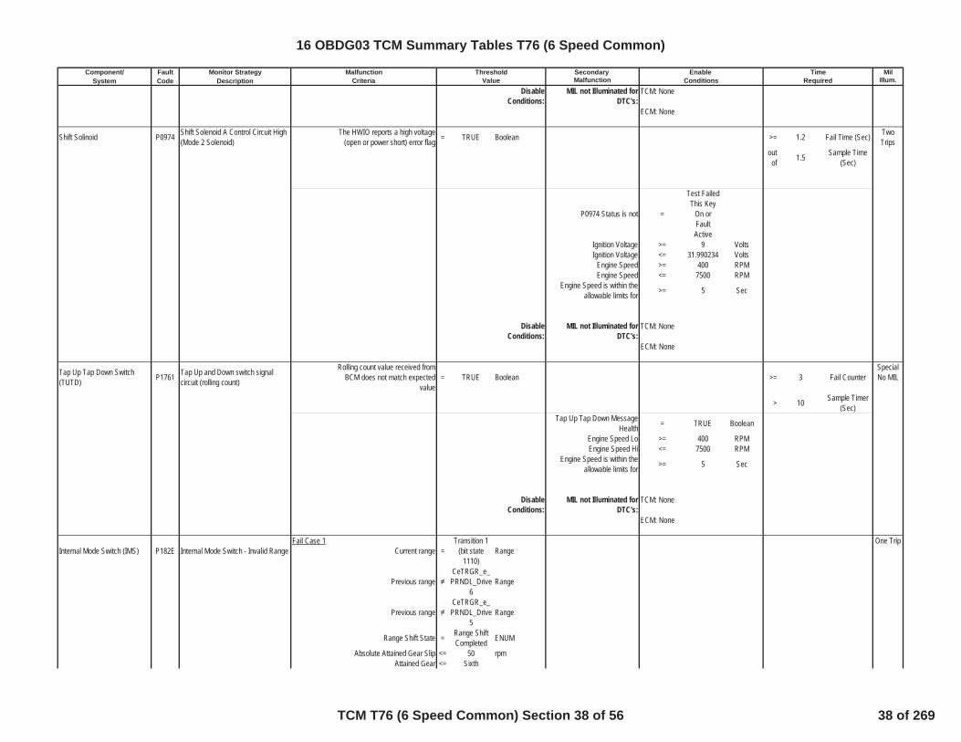
Shift Solinoid P0974 Shift Solenoid A Control Circuit High(Mode 2 Solenoid)
The HWIO reports a high voltage(open or power short) error flag = TRUE Boolean >= 1.2 Fail Time (Sec) Two
Tripsoutof 1.5 Sample Time
(Sec)
P0974 Status is not =
Test FailedThis Key
On orFaultActive
Ignition Voltage >= 9 VoltsIgnition Voltage <= 31.990234 Volts
Engine Speed >= 400 RPMEngine Speed <= 7500 RPM
Engine Speed is within theallowable limits for >= 5 Sec
DisableConditions:
MIL not Illuminated forDTC's:
Tap Up Tap Down Switch(TUTD) P1761 Tap Up and Down switch signal
circuit (rolling count)
Rolling count value received fromBCM does not match expected
value= TRUE Boolean >= 3 Fail Counter
SpecialNo MIL
> 10 Sample Timer(Sec)
Tap Up Tap Down MessageHealth = TRUE Boolean
Engine Speed Lo >= 400 RPMEngine Speed Hi <= 7500 RPM
Engine Speed is within theallowable limits for >= 5 Sec
DisableConditions:
MIL not Illuminated forDTC's:
Internal Mode Switch (IMS) P182E Internal Mode Switch - Invalid RangeFail Case 1
Current range =Transition 1
(bit state1110)
RangeOne Trip
Previous rangeCeTRGR_e_PRNDL_Drive
6Range
Previous rangeCeTRGR_e_PRNDL_Drive
5Range
Range Shift State = Range ShiftCompleted ENUM
Absolute Attained Gear Slip <= 50 rpmAttained Gear <= Sixth
TCM: None
ECM: None
TCM: None
ECM: None
TCM: None
ECM: None
16 OBDG03 TCM Summary Tables T76 (6 Speed Common)
TCM T76 (6 Speed Common) Section 38 of 56 38 of 269

Component/ Fault Monitor Strategy Secondary MilSystem Code Description Malfunction Illum.
Malfunction Threshold Enable TimeCriteria Value Conditions Required
Attained Gear >= FirstThrottle Position Available = TRUE
Throttle Position >= 8.000183105 pctOutput Speed >= 200 rpm
Engine Torque >= 50 NmEngine Torque <= 8191.75 Nm
If the above conditions are metthen Increment Fail Timer >= 1 Fail Seconds
If Fail Timer has Expired thenIncrement Fail Counter >= 5 Fail Counts
Fail Case 2 Output Speed <= 70 rpmThe following PRNDL sequenceevents occur in this exact order:
PRNDL state = Drive 6 (bitstate 0110) Range
PRNDL state = Drive 6 for >= 1 Sec
PRNDL state =Transition 8
(bit state0111)
Range
PRNDL state = Drive 6 (bitstate 0110) Range
PRNDL state =Transition 1
(bit state1110)
Range
Above sequencing occurs in <= 1 SecNeutral Idle Mode = Inactive
If all conditions above are metIncrement delay Timer
If the below two conditions aremet Increment Fail Timer >= 3 Fail Seconds
delay timer >= 1 SecInput Speed >= 400 Sec
If Fail Timer has Expired thenIncrement Fail Counter >= 2 Fail Counts
Fail Case 3Current range =
Transition 13(bit state
0010)Range Previous range
CeTRGR_e_PRNDL_Drive5
Engine Torque >= -8192 Nm Previous rangeCeTRGR_e_PRNDL_Drive5
Engine Torque <= 8191.75 Nm IMS is 7 position configuration = 0 Boolean
If the above conditions are metthen, Increment Fail Timer
If the "IMS 7 Position config" =1 then the "previous range"criteria above must also besatsified when the "current
range" = "Transition 13"
>= 0.225 Seconds
If Fail Timer has Expired thenIncrement Fail Counter >= 15 Fail Counts
Fail Case 4
Current range = Transition 8
(bit state0111)
RangeDisable Fail Case 4 if last
positive range was Drive 6 andcurrent range is transition 8
Inhibit bit (see definition) = FALSE
Set inhibit bit true if PRNDL =1100 (rev) or 0100 (Rev-Neu
transition 11)Set inhibit bit false if PRNDL =
1001 (park)
16 OBDG03 TCM Summary Tables T76 (6 Speed Common)
TCM T76 (6 Speed Common) Section 39 of 56 39 of 269

Component/ Fault Monitor Strategy Secondary MilSystem Code Description Malfunction Illum.
Malfunction Threshold Enable TimeCriteria Value Conditions RequiredSteady State Engine Torque >= 100 NmSteady State Engine Torque <= 8191.75 Nm
If the above conditions are metthen Increment Fail Timer >= 0.225 Seconds
If the above Condtions have beenmet, Increment Fail Counter >= 15 Fail Counts
Fail Case 5 Throttle Position Available = TRUE BooleanThe following PRNDL sequenceevents occur in this exact order:
PRNDL State = Reverse (bitstate 1100) Range
PRNDL State =Transition 11
(bit state0100)
Range
PRNDL State = Neutral (bitstate 0101) Range
PRNDL State =Transition 11
(bit state0100)
Range
Above sequencing occurs in <= 1 SecThen delay timer increments
Delay timer >= 5 sec
Range Shift State = Range ShiftComplete
Absolute Attained Gear Slip <= 50 rpmAttained Gear <= SixthAttained Gear >= First
Throttle Position >= 8.000183105 pctOutput Speed >= 200 rpm
If the above conditions are metIncrement Fail Timer >= 20 Seconds
Fail Case 6Current range =
Illegal (bitstate 0000 or1000 or 0001)
A Open Circuit Definition (flagset false if the following
conditions are met):
and Current Range
Transition11 (bitstate0100)
A Open Circuit (See Definition) = FALSE Boolean or
Last positive stateNeutral (bit
state0101)
or
Previous transition state Transition8 (bit state
0111)Fail case 5 delay timer = 0 sec
If the above Condtions are metthen, Increment Fail timer >= 6.25 Seconds
Fail Case 7 Current PRNDL State = PRNDL circuitABCP = 1101 Range
and
Previous PRNDL state = PRNDL circuitABCP =1111 Range
Input Speed >= 150 RPMReverse Trans Ratio <= 2.736938477 ratio
16 OBDG03 TCM Summary Tables T76 (6 Speed Common)
TCM T76 (6 Speed Common) Section 40 of 56 40 of 269

Component/ Fault Monitor Strategy Secondary MilSystem Code Description Malfunction Illum.
Malfunction Threshold Enable TimeCriteria Value Conditions Required
Reverse Trans Ratio >= 3.149047852 ratioIf the above Condtions are met
then, Increment Fail timer >= 6.25 Seconds
P182E will report test fail whenany of the above 7 fail cases are
met
Ignition Voltage Lo >= 9 VoltsIgnition Voltage Hi <= 31.990234 VoltsEngine Speed Lo >= 400 RPMEngine Speed Hi <= 7500 RPM
Engine Speed is within theallowable limits for >= 5 Sec
Engine Torque Signal Valid = TRUE Boolean
DisableConditions:
MIL not Illuminated forDTC's:
Internal Mode Switch (IMS) P1915Internal Mode Switch Does NotIndicate Park/Neutral (P/N) DuringStart
PRNDL State is Park orNeutral Enumeration
One Trip
The following events must occurSequentially
Initial Engine speed <= 50 RPM >= 0.25 Enable Time(Sec)
ThenEngine Speed Between Following
CalsEngine Speed Lo Hist >= 50 RPM
Engine Speed Hi Hist <= 480 RPM >= 0.06875 Enable Time(Sec)
ThenFinal Engine Speed >= 650 RPM
Final Transmission Input Speed >= 40 RPM >= 1.25 Fail Time (Sec)
DTC has Ran this Key Cycle? = FALSE Boolean
Ignition Voltage Lo >= 6 VIgnition Voltage Hi <= 31.990234 V
Ignition Voltage Hyst High(enables above this value) >= 5 V
Ignition Voltage Hyst Low(disabled below this value) <= 2 V
Transmission Output Speed <= 90 rpm
TCM: P0716, P0717, P0722, P0723,P07C0, P07BF, P077C, P077D
ECM: P0101, P0102, P0103, P0106,P0107, P0108, P0171, P0172, P0174,P0175, P0201, P0202, P0203, P0204,P0205, P0206, P0207, P0208, P0300,P0301, P0302, P0303, P0304, P0305,P0306, P0307, P0308, P0401, P042E
16 OBDG03 TCM Summary Tables T76 (6 Speed Common)
TCM T76 (6 Speed Common) Section 41 of 56 41 of 269

Component/ Fault Monitor Strategy Secondary MilSystem Code Description Malfunction Illum.
Malfunction Threshold Enable TimeCriteria Value Conditions Required
P1915 Status is
Test FailedThis Key
On orFaultActive
DisableConditions:
MIL not Illuminated forDTC's:
Transmission Control Module(TCM) P2534 Ignition Switch Run/Start Position
Circuit LowTCM Run crank active (based on
voltage thresholds below) = FALSE Boolean One Trip
Ignition Voltage High Hyst (runcrank goes true when above this
value)5 Volts >= 280 Fail Counts
(25ms loop)
Ignition Voltage Low Hyst (runcrank goes false when below this
value)2 Volts Out
of 280 Sample Counts(25ms loop)
ECM run/crank active statusavailable = TRUE Boolean
ECM run/crank active status = TRUE Boolean
DisableConditions:
MIL not Illuminated forDTC's:
Transmission Control Module(TCM) P2535 Ignition Switch Run/Start Position
Circuit HighTCM Run crank active (based on
voltage thresholds below) = TRUE Boolean One Trip
Ignition Voltage High Hyst (runcrank goes true when above this
value)5 Volts >= 280 Fail Counts
(25ms loop)
Ignition Voltage Low Hyst (runcrank goes false when below this
value)2 Volts Out
of 280 Sample Counts(25ms loop)
ECM run/crank active statusavailable = TRUE Boolean
ECM run/crank active status = FALSE Boolean
DisableConditions:
MIL not Illuminated forDTC's:
Variable Bleed Solenoid (VBS) P2714 Pressure Control (PC) Solenoid DStuck Off [CB26]
Fail Case 1 Case: Steady State 2nd Gear One Trip
Gear slip >= 400 RPM >=
Please SeeTable 5 For
Neutral TimeCal
Neutral Timer(Sec)
Intrusive test:commanded 3rd gear
TCM: P0722, P0723
ECM: None
TCM: None
ECM: None
TCM: None
ECM: None
16 OBDG03 TCM Summary Tables T76 (6 Speed Common)
TCM T76 (6 Speed Common) Section 42 of 56 42 of 269
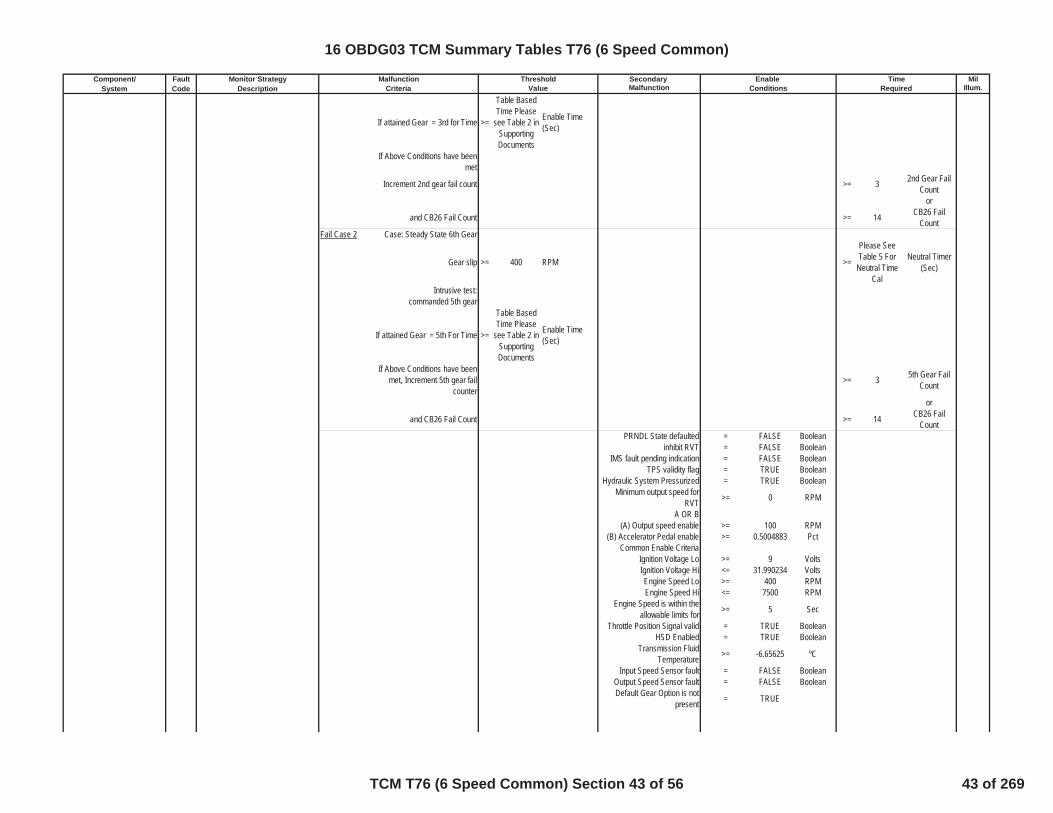
Component/ Fault Monitor Strategy Secondary MilSystem Code Description Malfunction Illum.
Malfunction Threshold Enable TimeCriteria Value Conditions Required
If attained Gear = 3rd for Time >=
Table BasedTime Please
see Table 2 inSupportingDocuments
Enable Time(Sec)
If Above Conditions have beenmet
Increment 2nd gear fail count >= 3 2nd Gear FailCount
or
and CB26 Fail Count >= 14 CB26 FailCount
Fail Case 2 Case: Steady State 6th Gear
Gear slip >= 400 RPM >=
Please SeeTable 5 For
Neutral TimeCal
Neutral Timer(Sec)
Intrusive test:commanded 5th gear
If attained Gear = 5th For Time >=
Table BasedTime Please
see Table 2 inSupportingDocuments
Enable Time(Sec)
If Above Conditions have beenmet, Increment 5th gear fail
counter>= 3 5th Gear Fail
Count
or
and CB26 Fail Count >= 14 CB26 FailCount
PRNDL State defaulted = FALSE Booleaninhibit RVT = FALSE Boolean
IMS fault pending indication = FALSE BooleanTPS validity flag = TRUE Boolean
Hydraulic System Pressurized = TRUE BooleanMinimum output speed for
RVT >= 0 RPM
A OR B(A) Output speed enable >= 100 RPM
(B) Accelerator Pedal enable >= 0.5004883 PctCommon Enable Criteria
Ignition Voltage Lo >= 9 VoltsIgnition Voltage Hi <= 31.990234 VoltsEngine Speed Lo >= 400 RPMEngine Speed Hi <= 7500 RPM
Engine Speed is within theallowable limits for >= 5 Sec
Throttle Position Signal valid = TRUE BooleanHSD Enabled = TRUE Boolean
Transmission FluidTemperature >= -6.65625 ºC
Input Speed Sensor fault = FALSE BooleanOutput Speed Sensor fault = FALSE BooleanDefault Gear Option is not
present = TRUE
16 OBDG03 TCM Summary Tables T76 (6 Speed Common)
TCM T76 (6 Speed Common) Section 43 of 56 43 of 269

Component/ Fault Monitor Strategy Secondary MilSystem Code Description Malfunction Illum.
Malfunction Threshold Enable TimeCriteria Value Conditions Required
DisableConditions:
MIL not Illuminated forDTC's:
Variable Bleed Solenoid (VBS) P2715 Pressure Control (PC) Solenoid DStuck On [CB26] (Dynamic)
Primary Offgoing Clutch isexhausted (See Table 13 in
Supporting Documents forExhaust Delay Timers)
= TRUE Boolean
One Trip
Primary Oncoming ClutchPressure Command Status = Maximum
pressurized
Primary Offgoing Clutch PressureCommand Status =
Clutchexhaust
command
Range Shift Status Initial ClutchControl
Attained Gear Slip <= 50 RPM
If above coditons are true,increment appropriate Fail 1
Timers Below:fail timer 1
(2-1 shifting with throttle) >= 0.400390625 Fail Time (Sec)
fail timer 1(2-1 shifting without throttle) >= 0.5 Fail Time (Sec)
fail timer 1(2-3 shifting with throttle) >= 0.400390625 Fail Time (Sec)
fail timer 1(2-3 shifting without throttle) >= 0.5 Fail Time (Sec)
fail timer 1(2-4 shifting with throttle) >= 0.400390625 Fail Time (Sec)
fail timer 1(2-4 shifting without throttle) >= 0.5 Fail Time (Sec)
fail timer 1(6-4 shifting with throttle) >= 0.400390625 Fail Time (Sec)
fail timer 1(6-4 shifting without throttle) >= 0.5 Fail Time (Sec)
fail timer 1(6-5 shifting with throttle) >= 0.700195313 Fail Time (Sec)
fail timer 1(6-5 shifting without throttle) >= 0.5 Fail Time (Sec)
TCM: P0716, P0717, P0722, P0723,P182E
ECM: P0101, P0102, P0103, P0106,P0107, P0108, P0171, P0172, P0174,P0175, P0201, P0202, P0203, P0204,P0205, P0206, P0207, P0208, P0300,P0301, P0302, P0303, P0304, P0305,P0306, P0307, P0308, P0401, P042E
16 OBDG03 TCM Summary Tables T76 (6 Speed Common)
TCM T76 (6 Speed Common) Section 44 of 56 44 of 269

Component/ Fault Monitor Strategy Secondary MilSystem Code Description Malfunction Illum.
Malfunction Threshold Enable TimeCriteria Value Conditions Required
If Attained Gear Slip is Less thanAbove Cal Increment Fail Timers >=
Total FailTime = (Fail 1+ Fail 2) See
EnableTimers for FailTimer 1, andReferenceSupportingTable 15 forFail Timer 2
sec
If fail timer is greater thanthreshold increment corresponding
gear fail counter and total failcounter
2nd gear fail counter >= 3 Fail CounterFrom 2nd Gear
OR
6th gear fail counter >= 3 Fail CounterFrom 6th Gear
OR
total fail counter >= 3 Total FailCounter
TUT Enable temperature >= -6.65625 ºCInput Speed Sensor fault = FALSE Boolean
Output Speed Sensor fault = FALSE BooleanCommand / Attained Gear 1st Boolean
High Side Driver ON = TRUE Booleanoutput speed limit for TUT >= 200 RPM
input speed limit for TUT >= 200 RPMPRNDL state defaulted = FALSE Boolean
IMS Fault Pending = FALSE BooleanService Fast Learn Mode = FALSE Boolean
HSD Enabled = TRUE Boolean
DisableConditions:
MIL not Illuminated forDTC's:
Variable Bleed Solenoid (VBS) P2715 Pressure Control (PC) Solenoid DStuck On [CB26] (Steady State)
Fail Case 1 Case: Steady State 1st One Trip
Attained Gear slip >= 400 RPM
If the Above is True for Time >=
Table BasedTime Please
Refer to Table4 in
supportingdocuments
Enable Time(Sec)
Intrusive test:(CBR1 clutch exhausted)
TCM: P0716, P0717, P0722, P0723,P182E
ECM: P0101, P0102, P0103, P0106,P0107, P0108, P0171, P0172, P0174,P0175, P0201, P0202, P0203, P0204,P0205, P0206, P0207, P0208, P0300,P0301, P0302, P0303, P0304, P0305,P0306, P0307, P0308, P0401, P042E
16 OBDG03 TCM Summary Tables T76 (6 Speed Common)
TCM T76 (6 Speed Common) Section 45 of 56 45 of 269
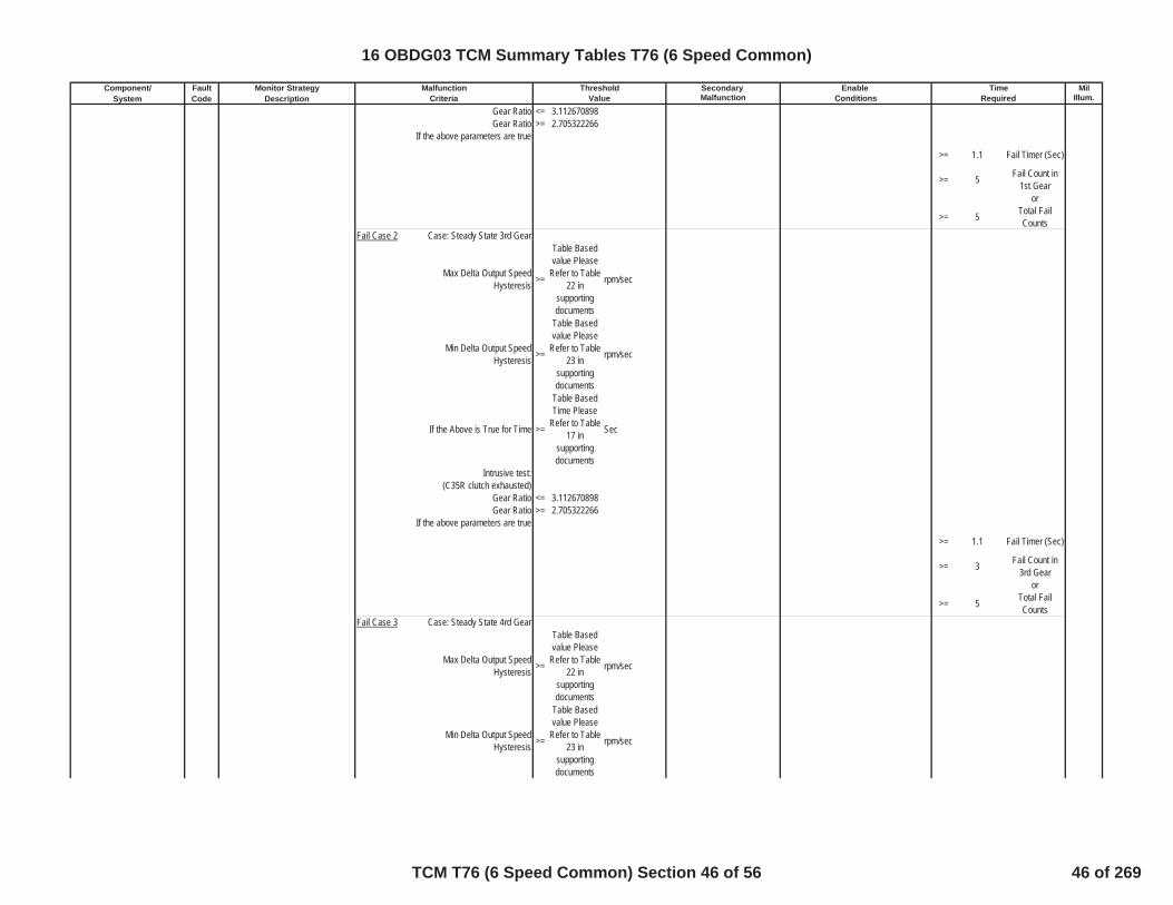
Component/ Fault Monitor Strategy Secondary MilSystem Code Description Malfunction Illum.
Malfunction Threshold Enable TimeCriteria Value Conditions Required
Gear Ratio <= 3.112670898Gear Ratio >= 2.705322266
If the above parameters are true
>= 1.1 Fail Timer (Sec)
>= 5 Fail Count in1st Gear
or
>= 5 Total FailCounts
Fail Case 2 Case: Steady State 3rd Gear
Max Delta Output SpeedHysteresis >=
Table Basedvalue Please
Refer to Table22 in
supportingdocuments
rpm/sec
Min Delta Output SpeedHysteresis >=
Table Basedvalue Please
Refer to Table23 in
supportingdocuments
rpm/sec
If the Above is True for Time >=
Table BasedTime Please
Refer to Table17 in
supportingdocuments
Sec
Intrusive test: (C35R clutch exhausted)
Gear Ratio <= 3.112670898Gear Ratio >= 2.705322266
If the above parameters are true
>= 1.1 Fail Timer (Sec)
>= 3 Fail Count in3rd Gear
or
>= 5 Total FailCounts
Fail Case 3 Case: Steady State 4rd Gear
Max Delta Output SpeedHysteresis >=
Table Basedvalue Please
Refer to Table22 in
supportingdocuments
rpm/sec
Min Delta Output SpeedHysteresis >=
Table Basedvalue Please
Refer to Table23 in
supportingdocuments
rpm/sec
16 OBDG03 TCM Summary Tables T76 (6 Speed Common)
TCM T76 (6 Speed Common) Section 46 of 56 46 of 269

Component/ Fault Monitor Strategy Secondary MilSystem Code Description Malfunction Illum.
Malfunction Threshold Enable TimeCriteria Value Conditions Required
If the Above is True for Time >=
Table BasedTime Please
Refer to Table17 in
supportingdocuments
Sec
Intrusive test: (C1234 clutch exhausted)
Gear Ratio <= 0.798217773Gear Ratio >= 0.693725586
If the above parameters are true
>= 1.1 Fail Timer (Sec)
>= 3 Fail Count in4th Gear
or
>= 5 Total FailCounts
Fail Case 4 Case: Steady State 5th Gear
Max Delta Output SpeedHysteresis >=
Table Basedvalue Please
Refer to Table22 in
supportingdocuments
rpm/sec
Min Delta Output SpeedHysteresis >=
Table Basedvalue Please
Refer to Table23 in
supportingdocuments
rpm/sec
If the Above is True for Time >=
Table BasedTime Please
Refer to Table17 in
supportingdocuments
Sec
Intrusive test: (C35R clutch exhausted)
Gear Ratio <= 0.798217773Gear Ratio >= 0.693725586
If the above parameters are true
>= 1.1 Fail Timer (Sec)
>= 3 Fail Count in5th Gear
or
>= 5 Total FailCounts
PRNDL State defaulted = FALSE Booleaninhibit RVT = FALSE Boolean
IMS fault pending indication = FALSE Booleanoutput speed >= 0 RPM
TPS validity flag = TRUE BooleanHSD Enabled = TRUE Boolean
Hydraulic_System_Pressurized = TRUE Boolean
16 OBDG03 TCM Summary Tables T76 (6 Speed Common)
TCM T76 (6 Speed Common) Section 47 of 56 47 of 269
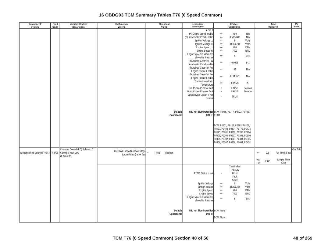
Component/ Fault Monitor Strategy Secondary MilSystem Code Description Malfunction Illum.
Malfunction Threshold Enable TimeCriteria Value Conditions Required
A OR B(A) Output speed enable >= 100 Nm
(B) Accelerator Pedal enable >= 0.5004883 NmIgnition Voltage Lo >= 9 VoltsIgnition Voltage Hi <= 31.990234 VoltsEngine Speed Lo >= 400 RPMEngine Speed Hi <= 7500 RPM
Engine Speed is within theallowable limits for >= 5 Sec
if Attained Gear=1st FWAccelerator Pedal enable >= 10.00061 Pct
if Attained Gear=1st FWEngine Torque Enable >= 45 Nm
if Attained Gear=1st FWEngine Torque Enable <= 8191.875 Nm
Transmission FluidTemperature >= -6.65625 ºC
Input Speed Sensor fault = FALSE BooleanOutput Speed Sensor fault = FALSE BooleanDefault Gear Option is not
present = TRUE
DisableConditions:
MIL not Illuminated forDTC's:
Variable Bleed Solenoid (VBS) P2720Pressure Control (PC) Solenoid DControl Circuit Low(CB26 VBS)
The HWIO reports a low voltage(ground short) error flag = TRUE Boolean >= 0.3 Fail Time (Sec)
One Trip
outof 0.375 Sample Time
(Sec)
P2770 Status is not =
Test FailedThis Key
On orFaultActive
Ignition Voltage >= 9 VoltsIgnition Voltage <= 31.990234 Volts
Engine Speed >= 400 RPMEngine Speed <= 7500 RPM
Engine Speed is within theallowable limits for >= 5 Sec
DisableConditions:
MIL not Illuminated forDTC's:
TCM: P0716, P0717, P0722, P0723,P182E
ECM: P0101, P0102, P0103, P0106,P0107, P0108, P0171, P0172, P0174,P0175, P0201, P0202, P0203, P0204,P0205, P0206, P0207, P0208, P0300,P0301, P0302, P0303, P0304, P0305,P0306, P0307, P0308, P0401, P042E
TCM: None
ECM: None
16 OBDG03 TCM Summary Tables T76 (6 Speed Common)
TCM T76 (6 Speed Common) Section 48 of 56 48 of 269

Component/ Fault Monitor Strategy Secondary MilSystem Code Description Malfunction Illum.
Malfunction Threshold Enable TimeCriteria Value Conditions Required
Variable Bleed Solenoid (VBS) P2721Pressure Control (PC) Solenoid DControl Circuit High(CB26 VBS)
The HWIO reports a high voltage(open or power short) error flag = TRUE Boolean >= 0.3 Fail Time (Sec)
One Trip
outof 0.375 Sample Time
(Sec)
P2721 Status is not =
Test FailedThis Key
On orFaultActive
Ignition Voltage >= 9 VoltsIgnition Voltage <= 31.990234 Volts
Engine Speed >= 400 RPMEngine Speed <= 7500 RPM
Engine Speed is within theallowable limits for >= 5 Sec
DisableConditions:
MIL not Illuminated forDTC's:
Variable Bleed Solenoid (VBS) P2723 Pressure Control (PC) Solenoid EStuck Off
Fail Case 1 Case: Steady State 1st Gear One Trip
Gear slip >= 400 RPM >=
Please SeeTable 5 For
Neutral TimeCal
Neutral Timer(Sec)
Intrusive test:commanded 2nd gear
If attained Gear 2nd for Time >=
Please referto Table 3 inSupportingDocuments
Shift Time (Sec)
If Above Conditions have beenmet, Increment 1st gear fail
counter>= 2 1st Gear Fail
Count
or
and C1234 fail counter >= 14 C1234 ClutchFail Count
Fail Case 2 Case: Steady State 2nd Gear
Gear slip >= 400 RPM >=
Please SeeTable 5 For
Neutral TimeCal
Neutral Timer(Sec)
Intrusive test:commanded 3rd gear
If attained Gear 3rd for Time >=
Please referto Table 3 inSupportingDocuments
Shift Time (Sec)
If Above Conditions have beenmet, Increment 2nd gear fail
counter>= 2 2nd Gear Fail
Count
or
and C1234 fail counter >= 14 C1234 ClutchFail Count
TCM: None
ECM: None
16 OBDG03 TCM Summary Tables T76 (6 Speed Common)
TCM T76 (6 Speed Common) Section 49 of 56 49 of 269

Component/ Fault Monitor Strategy Secondary MilSystem Code Description Malfunction Illum.
Malfunction Threshold Enable TimeCriteria Value Conditions Required
Fail Case 3 Case: Steady State 3rd Gear
Gear slip >= 400 RPM >=
Please SeeTable 5 For
Neutral TimeCal
Neutral Timer(Sec)
Intrusive test:commanded 4th gear
If attained Gear 4th for time >=
Please referto Table 3 inSupportingDocuments
Shift Time (Sec)
If Above Conditions have beenmet, Increment 3rd gear fail
counter>= 2 3rd Gear Fail
Count
or
and C1234 fail counter >= 14 C1234 ClutchFail Count
Fail Case 4 Case: Steady State 4th Gear
Gear slip >= 400 RPM >=
Please SeeTable 5 For
Neutral TimeCal
Neutral Timer(Sec)
Intrusive test:commanded 5th gear
If attained Gear = 5th For Time >=
Please referto Table 3 inSupportingDocuments
Shift Time (Sec)
If Above Conditions have beenmet, Increment 4th gear fail
counter>= 3 4th Gear Fail
Count
or
and C1234 fail counter >= 14 C1234 ClutchFail Count
PRNDL State defaulted = FALSE Booleaninhibit RVT = FALSE Boolean
IMS fault pending indication = FALSE BooleanTPS validity flag = TRUE Boolean
Hydraulic System Pressurized = TRUE BooleanMinimum output speed for
RVT >= 0 RPM
A OR B(A) Output speed enable >= 100 RPM
(B) Accelerator Pedal enable >= 0.5004883 PctCommon Enable Criteria
Ignition Voltage Lo >= 9 VoltsIgnition Voltage Hi <= 31.990234 VoltsEngine Speed Lo >= 400 RPMEngine Speed Hi <= 7500 RPM
Engine Speed is within theallowable limits for >= 5 Sec
Throttle Position Signal valid = TRUE BooleanHSD Enabled = TRUE Boolean
Transmission FluidTemperature >= -6.65625 ºC
Input Speed Sensor fault = FALSE BooleanOutput Speed Sensor fault = FALSE Boolean
16 OBDG03 TCM Summary Tables T76 (6 Speed Common)
TCM T76 (6 Speed Common) Section 50 of 56 50 of 269
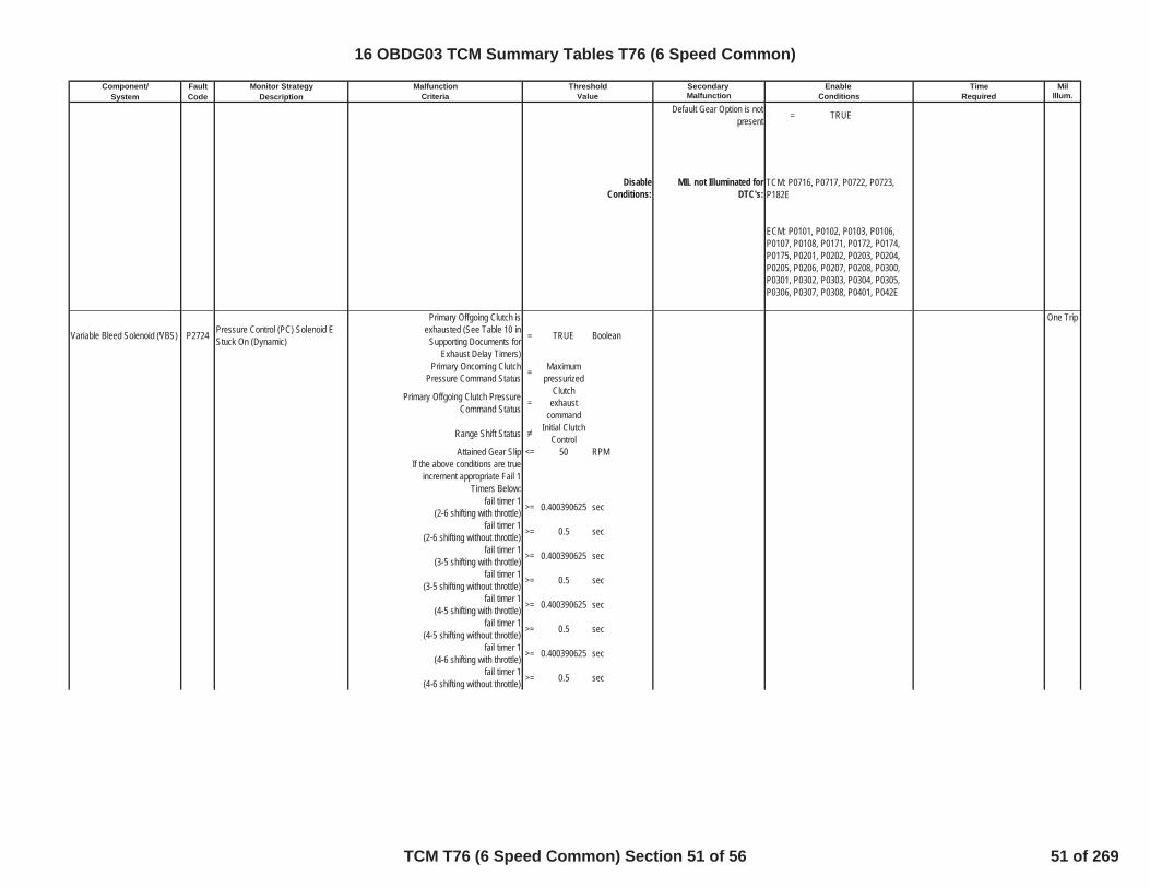
Component/ Fault Monitor Strategy Secondary MilSystem Code Description Malfunction Illum.
Malfunction Threshold Enable TimeCriteria Value Conditions Required
Default Gear Option is notpresent = TRUE
DisableConditions:
MIL not Illuminated forDTC's:
Variable Bleed Solenoid (VBS) P2724 Pressure Control (PC) Solenoid EStuck On (Dynamic)
Primary Offgoing Clutch isexhausted (See Table 10 in
Supporting Documents forExhaust Delay Timers)
= TRUE Boolean
One Trip
Primary Oncoming ClutchPressure Command Status = Maximum
pressurized
Primary Offgoing Clutch PressureCommand Status =
Clutchexhaust
command
Range Shift Status Initial ClutchControl
Attained Gear Slip <= 50 RPMIf the above conditions are true
increment appropriate Fail 1Timers Below:
fail timer 1(2-6 shifting with throttle) >= 0.400390625 sec
fail timer 1(2-6 shifting without throttle) >= 0.5 sec
fail timer 1(3-5 shifting with throttle) >= 0.400390625 sec
fail timer 1(3-5 shifting without throttle) >= 0.5 sec
fail timer 1(4-5 shifting with throttle) >= 0.400390625 sec
fail timer 1(4-5 shifting without throttle) >= 0.5 sec
fail timer 1(4-6 shifting with throttle) >= 0.400390625 sec
fail timer 1(4-6 shifting without throttle) >= 0.5 sec
TCM: P0716, P0717, P0722, P0723,P182E
ECM: P0101, P0102, P0103, P0106,P0107, P0108, P0171, P0172, P0174,P0175, P0201, P0202, P0203, P0204,P0205, P0206, P0207, P0208, P0300,P0301, P0302, P0303, P0304, P0305,P0306, P0307, P0308, P0401, P042E
16 OBDG03 TCM Summary Tables T76 (6 Speed Common)
TCM T76 (6 Speed Common) Section 51 of 56 51 of 269
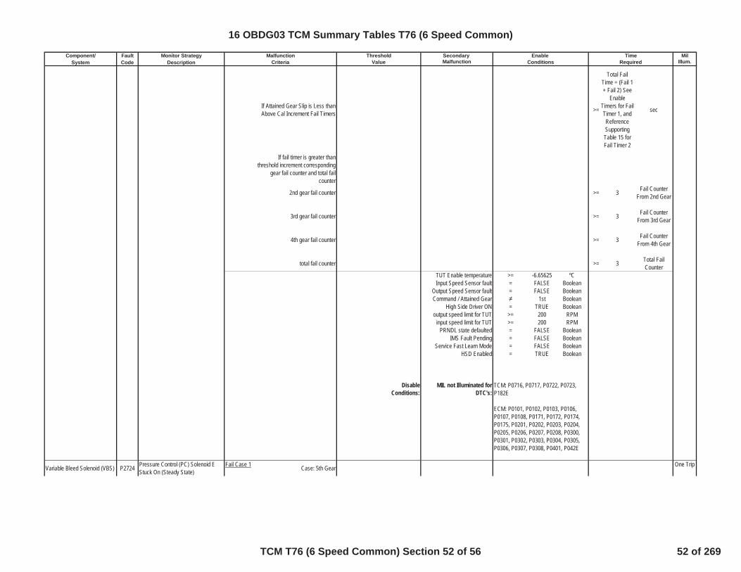
Component/ Fault Monitor Strategy Secondary MilSystem Code Description Malfunction Illum.
Malfunction Threshold Enable TimeCriteria Value Conditions Required
If Attained Gear Slip is Less thanAbove Cal Increment Fail Timers >=
Total FailTime = (Fail 1+ Fail 2) See
EnableTimers for FailTimer 1, andReferenceSupportingTable 15 forFail Timer 2
sec
If fail timer is greater thanthreshold increment corresponding
gear fail counter and total failcounter
2nd gear fail counter >= 3 Fail CounterFrom 2nd Gear
3rd gear fail counter >= 3 Fail CounterFrom 3rd Gear
4th gear fail counter >= 3 Fail CounterFrom 4th Gear
total fail counter >= 3 Total FailCounter
TUT Enable temperature >= -6.65625 ºCInput Speed Sensor fault = FALSE Boolean
Output Speed Sensor fault = FALSE BooleanCommand / Attained Gear 1st Boolean
High Side Driver ON = TRUE Booleanoutput speed limit for TUT >= 200 RPM
input speed limit for TUT >= 200 RPMPRNDL state defaulted = FALSE Boolean
IMS Fault Pending = FALSE BooleanService Fast Learn Mode = FALSE Boolean
HSD Enabled = TRUE Boolean
DisableConditions:
MIL not Illuminated forDTC's:
Variable Bleed Solenoid (VBS) P2724 Pressure Control (PC) Solenoid EStuck On (Steady State)
Fail Case 1 Case: 5th Gear One Trip
TCM: P0716, P0717, P0722, P0723,P182E
ECM: P0101, P0102, P0103, P0106,P0107, P0108, P0171, P0172, P0174,P0175, P0201, P0202, P0203, P0204,P0205, P0206, P0207, P0208, P0300,P0301, P0302, P0303, P0304, P0305,P0306, P0307, P0308, P0401, P042E
16 OBDG03 TCM Summary Tables T76 (6 Speed Common)
TCM T76 (6 Speed Common) Section 52 of 56 52 of 269

Component/ Fault Monitor Strategy Secondary MilSystem Code Description Malfunction Illum.
Malfunction Threshold Enable TimeCriteria Value Conditions Required
Max Delta Output SpeedHysteresis >=
Table Basedvalue Please
Refer to Table22 in
supportingdocuments
rpm/sec
Min Delta Output SpeedHysteresis >=
Table Basedvalue Please
Refer to Table23 in
supportingdocuments
rpm/sec
If the Above is True for Time >=
Table BasedTime Please
Refer to Table17 in
supportingdocuments
Sec
Intrusive test:(C35R clutch exhausted)
Gear Ratio <= 1.529052734Gear Ratio >= 1.328979492
If the above parameters are true
>= 1.1 Fail Timer (Sec)
>= 3 Fail Count in5th Gear
OR
>= 3 Total FailCounts
Fail Case 2 Case: 6th Gear
Max Delta Output SpeedHysteresis >=
Table Basedvalue Please
Refer to Table22 in
supportingdocuments
rpm/sec
Min Delta Output SpeedHysteresis >=
Table Basedvalue Please
Refer to Table23 in
supportingdocuments
rpm/sec
If the Above is True for Time >=
Table BasedTime Please
Refer to Table17 in
supportingdocuments
Sec
Intrusive test:(CB26 clutch exhausted)
Gear Ratio <= 1.529052734Gear Ratio >= 1.328979492
If the above parameters are true
>= 1.1 Fail Timer (Sec)
16 OBDG03 TCM Summary Tables T76 (6 Speed Common)
TCM T76 (6 Speed Common) Section 53 of 56 53 of 269

Component/ Fault Monitor Strategy Secondary MilSystem Code Description Malfunction Illum.
Malfunction Threshold Enable TimeCriteria Value Conditions Required
>= 3 Fail Count in6th Gear
OR
>= 3 Total FailCounts
PRNDL State defaulted = FALSE Booleaninhibit RVT = FALSE Boolean
IMS fault pending indication = FALSE Booleanoutput speed >= 0 RPM
TPS validity flag = TRUE BooleanHSD Enabled = TRUE Boolean
Hydraulic_System_Pressurized = TRUE Boolean
A OR B(A) Output speed enable >= 100 Nm
(B) Accelerator Pedal enable >= 0.5004883 NmIgnition Voltage Lo >= 9 VoltsIgnition Voltage Hi <= 31.990234 VoltsEngine Speed Lo >= 400 RPMEngine Speed Hi <= 7500 RPM
Engine Speed is within theallowable limits for >= 5 Sec
if Attained Gear=1st FWAccelerator Pedal enable >= 10.00061 Pct
if Attained Gear=1st FWEngine Torque Enable >= 45 Nm
if Attained Gear=1st FWEngine Torque Enable <= 8191.875 Nm
Transmission FluidTemperature >= -6.65625 ºC
Input Speed Sensor fault = FALSE BooleanOutput Speed Sensor fault = FALSE BooleanDefault Gear Option is not
present = TRUE
DisableConditions:
MIL not Illuminated forDTC's:
Variable Bleed Solenoid (VBS) P2729Pressure Control (PC) Solenoid EControl Circuit Low(C1234 VBS)
The HWIO reports a low voltage(ground short) error flag = TRUE Boolean >= 0.3 Fail Time (Sec)
One Trip
outof 0.375 Sample Time
(Sec)
P2729 Status is not =
Test FailedThis Key
On orFaultActive
TCM: P0716, P0717, P0722, P0723,P182E
ECM: P0101, P0102, P0103, P0106,P0107, P0108, P0171, P0172, P0174,P0175, P0201, P0202, P0203, P0204,P0205, P0206, P0207, P0208, P0300,P0301, P0302, P0303, P0304, P0305,P0306, P0307, P0308, P0401, P042E
16 OBDG03 TCM Summary Tables T76 (6 Speed Common)
TCM T76 (6 Speed Common) Section 54 of 56 54 of 269
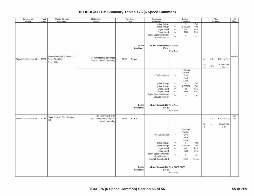
Component/ Fault Monitor Strategy Secondary MilSystem Code Description Malfunction Illum.
Malfunction Threshold Enable TimeCriteria Value Conditions Required
Ignition Voltage >= 9 VoltIgnition Voltage <= 31.990234 Volt
Engine Speed >= 400 RPMEngine Speed <= 7500 RPM
Engine Speed is within theallowable limits for >= 5 Sec
DisableConditions:
MIL not Illuminated forDTC's:
Variable Bleed Solenoid (VBS) P2730Pressure Control (PC) Solenoid EControl Circuit High(C1234 VBS)
The HWIO reports a high voltage(open or power short) error flag = TRUE Boolean >= 0.3 Fail Time (Sec)
One Trip
outof 0.375 Sample Time
(Sec)
P2730 Status is not =
Test FailedThis Key
On orFaultActive
Ignition Voltage >= 9 VoltIgnition Voltage <= 31.990234 Volt
Engine Speed >= 400 RPMEngine Speed <= 7500 RPM
Engine Speed is within theallowable limits for >= 5 Sec
DisableConditions:
MIL not Illuminated forDTC's:
Variable Bleed Solenoid (VBS) P2763 Torque Converter Clutch PressureHigh
The HWIO reports a lowpressure/high voltage (open or
power short) error flag= TRUE Boolean >= 4.4 Fail Time (Sec)
TwoTrips
outof 5 Sample Time
(Sec)
P2763 Status is not =
Test FailedThis Key
On orFaultActive
Ignition Voltage >= 9 VoltIgnition Voltage <= 31.990234 Volt
Engine Speed >= 400 RPMEngine Speed <= 7500 RPM
Engine Speed is within theallowable limits for >= 5 Sec
High Side Driver Enabled = TRUE Boolean
DisableConditions:
MIL not Illuminated forDTC's:
TCM: None
ECM: None
TCM: None
ECM: None
TCM: P0658, P0659
ECM: None
16 OBDG03 TCM Summary Tables T76 (6 Speed Common)
TCM T76 (6 Speed Common) Section 55 of 56 55 of 269

Component/ Fault Monitor Strategy Secondary MilSystem Code Description Malfunction Illum.
Malfunction Threshold Enable TimeCriteria Value Conditions Required
Variable Bleed Solenoid (VBS) P2764 Torque Converter Clutch PressureControl Solenoid Control Circuit Low
The HWIO reports a highpressure/low voltage (ground
short) error flag= TRUE Boolean >= 4.4 Fail Time (Sec)
One Trip
outof 5 Sample Time
(Sec)
P2764 Status is not =
Test FailedThis Key
On orFaultActive
Ignition Voltage >= 9 VoltIgnition Voltage <= 31.990234 Volt
Engine Speed >= 400 RPMEngine Speed <= 7500 RPM
Engine Speed is within theallowable limits for >= 5 Sec
High Side Driver Enabled = TRUE Boolean
DisableConditions:
MIL not Illuminated forDTC's:
Communication U0073 Controller Area Network BusCommunication Error
CAN Hardware Circuitry Detects aLow Voltage Error = TRUE Boolean >= 62 Fail counts (
10 seconds)One Trip
Delay timer >= 0.1125 sec Outof 70 Sample Counts
11 seconds)Stabilization delay >= 3 sec
Ignition Voltage >= 9 VoltIgnition Voltage <= 31.990234 Volt
Power Mode = Run
DisableConditions:
MIL not Illuminated forDTC's:
Communication U0100 Lost Communications with ECM(Engine Control Module)
CAN messages from ECM are notreceived by the TCM = TRUE Boolean >= 12 sec One Trip
Stabilization delay >= 3 secIgnition Voltage >= 9 VoltIgnition Voltage <= 31.990234 Volt
Power Mode = Run
DisableConditions:
MIL not Illuminated forDTC's:
TCM: None
ECM: None
TCM: U0073
ECM: None
TCM: P0658, P0659
ECM: None
16 OBDG03 TCM Summary Tables T76 (6 Speed Common)
TCM T76 (6 Speed Common) Section 56 of 56 56 of 269

Component/ Fault Monitor Strategy Secondary MilSystem Code Description Malfunction Illum.
Transmission Control Module(TCM) P0562 Ignition voltage at the TCM is low for
an extended period of time. Ignition Voltage <= 10 Volts = 8 Fail counts(1000ms loop)
No Mil
Outof 12 Sample Counts
(1000ms loop)Ignition Voltage Hyst Hi
(enabled above this value) > 5 Volts
Ignition Voltage Hyst Lo(disabled below this value) <= 2 Volts
Engine Speed > 1350 RPM
DisableConditions:
MIL not Illuminated forDTC's:
Transmission Control Module(TCM) P0563 Ignition voltage at the TCM is high
for an extended period of time. Ignition Voltage >= 18 Volts = 10 Fail counts(1000ms loop)
No Mil
Outof 12 Sample Counts
(1000ms loop)Ignition Voltage Hyst Hi
(enabled above this value) > 5 Volts
Ignition Voltage Hyst Lo(disabled below this value) <= 2 Volts
DisableConditions:
MIL not Illuminated forDTC's:
Transmission Control Module(TCM) P0602 Transmission Electro-Hydraulic
Control Module Not Programmed Non-Programmed TECHM Failure = TRUE Boolean RunsContinously
No Mil
DisableConditions:
MIL not Illuminated forDTC's:
High Side Driver 1 P0659 Actuator Supply Voltage Circuit High
During the controller power-up,prior to the HSD being turned on,
the HWIO reports that power shortfailure is
= TRUE Boolean >= 4 Fail Counts
No Mil
outof 6 Sample Counts
P0659 Status is not =
Test FailedThis Key
On orFaultActive
DisableConditions:
MIL not Illuminated forDTC's:
Mode Switch P071A Transmission Mode Switch A Circuit Tow Haul Mode Switch state = TRUE Boolean >= 600 Fail Time (Sec) No Mil
Ignition Voltage Lo >= 9 Volts
TCM: None
ECM: None
TCM: None
ECM: None
Malfunction Threshold Enable TimeCriteria Value Conditions Required
TCM: None
ECM: None
TCM: P0602
ECM: None
16 OBDG03 TCM Summary Tables T76 (6 Speed Unique)
TCM T76 (6 Speed Unique) Section 1 of 18 57 of 269

Component/ Fault Monitor Strategy Secondary MilSystem Code Description Malfunction Illum.
Malfunction Threshold Enable TimeCriteria Value Conditions Required
Ignition Voltage Hi <= 31.990234 VoltsEngine Speed Lo >= 400 RPMEngine Speed Hi <= 7500 RPM
Engine Speed is within theallowable limits for >= 5 Sec
DisableConditions:
MIL not Illuminated forDTC's:
Mode Switch P071D Transmission Mode Switch B Circuit Sport Mode Switch state = TRUE Boolean >= 600 Fail Time (Sec) No Mil
Ignition Voltage Lo >= 9 VoltsIgnition Voltage Hi <= 31.990234 VoltsEngine Speed Lo >= 400 RPMEngine Speed Hi <= 7500 RPM
Engine Speed is within theallowable limits for >= 5 Sec
DisableConditions:
MIL not Illuminated forDTC's:
Mode 2 Multiplex Valve P0756 Shift Solenoid Valve B Stuck Off Fail Case 1 Commanded Gear = 1st Locked No Mil
Gear Box Slip >= 400 RPM >=
Please Referto Table 5 inSupportingDocuments
Neutral Timer(Sec)
Intrusive Shift to 2ndCommanded Gear Previous = 1st Locked Gear
Gear Ratio <= 3.111816406Gear Ratio >= 2.704589844
If the above parameters are true>= 1 sec>= 3 counts
Ignition Voltage Lo >= 9 VoltsIgnition Voltage Hi <= 31.990234 VoltsEngine Speed Lo >= 400 RPMEngine Speed Hi <= 7500 RPM
Engine Speed is within theallowable limits for >= 5 Sec
Output Speed >= 110 RPMOR
TPS >= 0.5004883 %
Range Shift State =RangeShift
CompletedENUM
Transmission FluidTemperature >= -6.65625 ºC
High-Side Driver is Enabled = TRUE BooleanThrottle Position Signal Valid
from ECM = TRUE Boolean
Input Speed Sensor fault = FALSE BooleanOutput Speed Sensor fault = FALSE Boolean
TCM: P1762
ECM: None
TCM: P1762
ECM: None
16 OBDG03 TCM Summary Tables T76 (6 Speed Unique)
TCM T76 (6 Speed Unique) Section 2 of 18 58 of 269
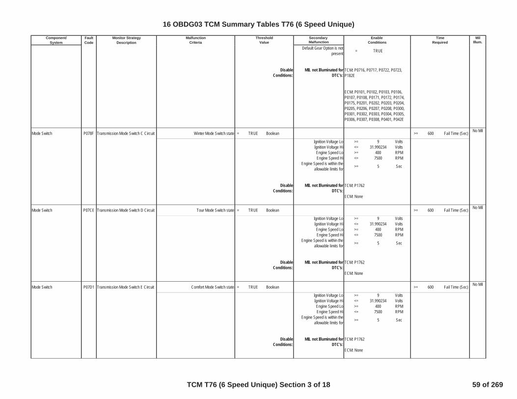
Component/ Fault Monitor Strategy Secondary MilSystem Code Description Malfunction Illum.
Malfunction Threshold Enable TimeCriteria Value Conditions Required
Default Gear Option is notpresent = TRUE
DisableConditions:
MIL not Illuminated forDTC's:
Mode Switch P078F Transmission Mode Switch C Circuit Winter Mode Switch state = TRUE Boolean >= 600 Fail Time (Sec) No Mil
Ignition Voltage Lo >= 9 VoltsIgnition Voltage Hi <= 31.990234 VoltsEngine Speed Lo >= 400 RPMEngine Speed Hi <= 7500 RPM
Engine Speed is within theallowable limits for >= 5 Sec
DisableConditions:
MIL not Illuminated forDTC's:
Mode Switch P07CE Transmission Mode Switch D Circuit Tour Mode Switch state = TRUE Boolean >= 600 Fail Time (Sec) No Mil
Ignition Voltage Lo >= 9 VoltsIgnition Voltage Hi <= 31.990234 VoltsEngine Speed Lo >= 400 RPMEngine Speed Hi <= 7500 RPM
Engine Speed is within theallowable limits for >= 5 Sec
DisableConditions:
MIL not Illuminated forDTC's:
Mode Switch P07D1 Transmission Mode Switch E Circuit Comfort Mode Switch state = TRUE Boolean >= 600 Fail Time (Sec) No Mil
Ignition Voltage Lo >= 9 VoltsIgnition Voltage Hi <= 31.990234 VoltsEngine Speed Lo >= 400 RPMEngine Speed Hi <= 7500 RPM
Engine Speed is within theallowable limits for >= 5 Sec
DisableConditions:
MIL not Illuminated forDTC's:
TCM: P0716, P0717, P0722, P0723,P182E
ECM: P0101, P0102, P0103, P0106,P0107, P0108, P0171, P0172, P0174,P0175, P0201, P0202, P0203, P0204,P0205, P0206, P0207, P0208, P0300,P0301, P0302, P0303, P0304, P0305,P0306, P0307, P0308, P0401, P042E
TCM: P1762
ECM: None
TCM: P1762
ECM: None
TCM: P1762
ECM: None
16 OBDG03 TCM Summary Tables T76 (6 Speed Unique)
TCM T76 (6 Speed Unique) Section 3 of 18 59 of 269
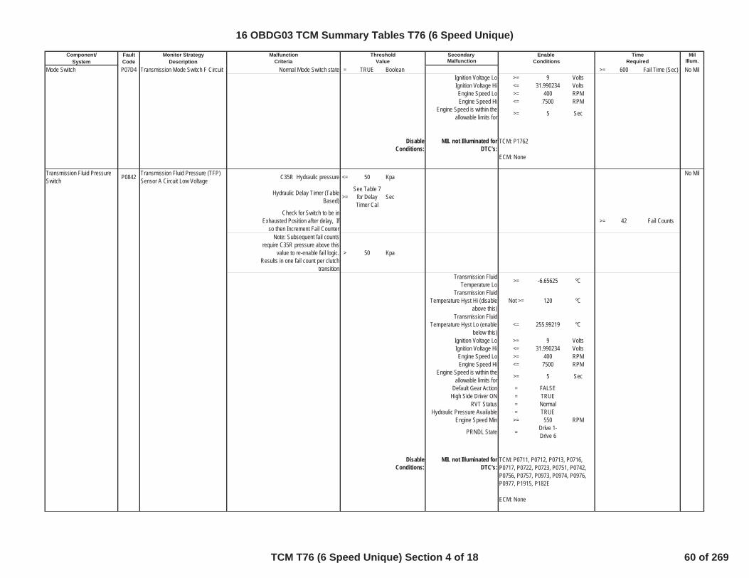
Component/ Fault Monitor Strategy Secondary MilSystem Code Description Malfunction Illum.
Malfunction Threshold Enable TimeCriteria Value Conditions Required
Mode Switch P07D4 Transmission Mode Switch F Circuit Normal Mode Switch state = TRUE Boolean >= 600 Fail Time (Sec) No MilIgnition Voltage Lo >= 9 VoltsIgnition Voltage Hi <= 31.990234 VoltsEngine Speed Lo >= 400 RPMEngine Speed Hi <= 7500 RPM
Engine Speed is within theallowable limits for >= 5 Sec
DisableConditions:
MIL not Illuminated forDTC's:
Transmission Fluid PressureSwitch P0842 Transmission Fluid Pressure (TFP)
Sensor A Circuit Low Voltage C35R Hydraulic pressure <= 50 Kpa No Mil
Hydraulic Delay Timer (TableBased) >=
See Table 7for DelayTimer Cal
Sec
Check for Switch to be inExhausted Position after delay, If
so then Increment Fail Counter>= 42 Fail Counts
Note: Subsequent fail countsrequire C35R pressure above this
value to re-enable fail logic.Results in one fail count per clutch
transition
> 50 Kpa
Transmission FluidTemperature Lo >= -6.65625 ºC
Transmission FluidTemperature Hyst Hi (disable
above this)Not >= 120 ºC
Transmission FluidTemperature Hyst Lo (enable
below this)<= 255.99219 ºC
Ignition Voltage Lo >= 9 VoltsIgnition Voltage Hi <= 31.990234 VoltsEngine Speed Lo >= 400 RPMEngine Speed Hi <= 7500 RPM
Engine Speed is within theallowable limits for >= 5 Sec
Default Gear Action = FALSEHigh Side Driver ON = TRUE
RVT Status = NormalHydraulic Pressure Available = TRUE
Engine Speed Min >= 550 RPM
PRNDL State = Drive 1-Drive 6
DisableConditions:
MIL not Illuminated forDTC's:
TCM: P1762
ECM: None
TCM: P0711, P0712, P0713, P0716,P0717, P0722, P0723, P0751, P0742,P0756, P0757, P0973, P0974, P0976,P0977, P1915, P182E
ECM: None
16 OBDG03 TCM Summary Tables T76 (6 Speed Unique)
TCM T76 (6 Speed Unique) Section 4 of 18 60 of 269
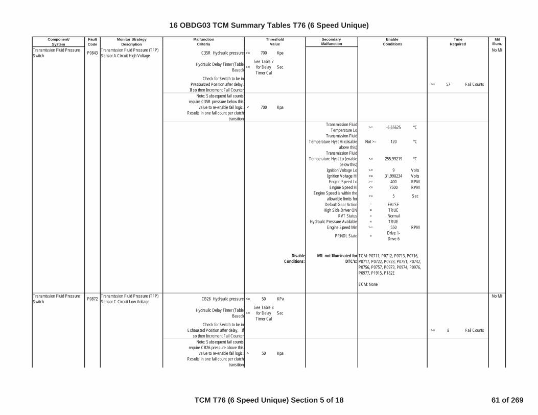
Component/ Fault Monitor Strategy Secondary MilSystem Code Description Malfunction Illum.
Malfunction Threshold Enable TimeCriteria Value Conditions Required
Transmission Fluid PressureSwitch P0843 Transmission Fluid Pressure (TFP)
Sensor A Circuit High Voltage C35R Hydraulic pressure >= 700 Kpa No Mil
Hydraulic Delay Timer (TableBased) >=
See Table 7for DelayTimer Cal
Sec
Check for Switch to be inPressurized Position after delay,If so then Increment Fail Counter
>= 57 Fail Counts
Note: Subsequent fail countsrequire C35R pressure below this
value to re-enable fail logic.Results in one fail count per clutch
transition
< 700 Kpa
Transmission FluidTemperature Lo >= -6.65625 ºC
Transmission FluidTemperature Hyst Hi (disable
above this)Not >= 120 ºC
Transmission FluidTemperature Hyst Lo (enable
below this)<= 255.99219 ºC
Ignition Voltage Lo >= 9 VoltsIgnition Voltage Hi <= 31.990234 VoltsEngine Speed Lo >= 400 RPMEngine Speed Hi <= 7500 RPM
Engine Speed is within theallowable limits for >= 5 Sec
Default Gear Action = FALSEHigh Side Driver ON = TRUE
RVT Status = NormalHydraulic Pressure Available = TRUE
Engine Speed Min >= 550 RPM
PRNDL State = Drive 1-Drive 6
DisableConditions:
MIL not Illuminated forDTC's:
Transmission Fluid PressureSwitch P0872 Transmission Fluid Pressure (TFP)
Sensor C Circuit Low Voltage CB26 Hydraulic pressure <= 50 KPa No Mil
Hydraulic Delay Timer (TableBased) >=
See Table 8for DelayTimer Cal
Sec
Check for Switch to be inExhausted Position after delay, If
so then Increment Fail Counter>= 8 Fail Counts
Note: Subsequent fail countsrequire CB26 pressure above this
value to re-enable fail logic.Results in one fail count per clutch
transition
> 50 Kpa
TCM: P0711, P0712, P0713, P0716,P0717, P0722, P0723, P0751, P0742,P0756, P0757, P0973, P0974, P0976,P0977, P1915, P182E
ECM: None
16 OBDG03 TCM Summary Tables T76 (6 Speed Unique)
TCM T76 (6 Speed Unique) Section 5 of 18 61 of 269
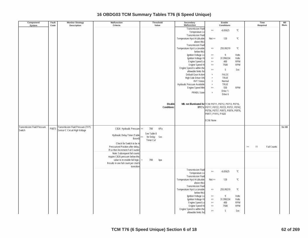
Component/ Fault Monitor Strategy Secondary MilSystem Code Description Malfunction Illum.
Malfunction Threshold Enable TimeCriteria Value Conditions Required
Transmission FluidTemperature Lo >= -6.65625 ºC
Transmission FluidTemperature Hyst Hi (disable
above this)Not >= 120 ºC
Transmission FluidTemperature Hyst Lo (enable
below this)<= 255.99219 ºC
Ignition Voltage Lo >= 9 VoltsIgnition Voltage Hi <= 31.990234 VoltsEngine Speed Lo >= 400 RPMEngine Speed Hi <= 7500 RPM
Engine Speed is within theallowable limits for >= 5 Sec
Default Gear Action = FALSEHigh Side Driver ON = TRUE
RVT Status = NormalHydraulic Pressure Available = TRUE
Engine Speed Min >= 550 RPM
PRNDL State = Drive 1-Drive 6
DisableConditions:
MIL not Illuminated forDTC's:
Transmission Fluid PressureSwitch P0873 Transmission Fluid Pressure (TFP)
Sensor C Circuit High Voltage CB26 Hydraulic Pressure >= 700 KPa No Mil
Hydraulic Delay Timer (TableBased) >=
See Table 8for DelayTimer Cal
Sec
Check for Switch to be inPressurized Position after delay,If so then Increment Fail Counter
>= 11 Fail Counts
Note: Subsequent fail countsrequire CB26 pressure below this
value to re-enable fail logic.Results in one fail count per clutch
transition
< 700 kpa
Transmission FluidTemperature Lo >= -6.65625 ºC
Transmission FluidTemperature Hyst Hi (disable
above this)Not >= 120 ºC
Transmission FluidTemperature Hyst Lo (enable
below this)<= 255.99219 ºC
Ignition Voltage Lo >= 9 VoltsIgnition Voltage Hi <= 31.990234 VoltsEngine Speed Lo >= 400 RPMEngine Speed Hi <= 7500 RPM
Engine Speed is within theallowable limits for >= 5 Sec
TCM: P0711, P0712, P0713, P0716,P0717, P0722, P0723, P0751, P0742,P0756, P0757, P0973, P0974, P0976,P0977, P1915, P182E
ECM: None
16 OBDG03 TCM Summary Tables T76 (6 Speed Unique)
TCM T76 (6 Speed Unique) Section 6 of 18 62 of 269
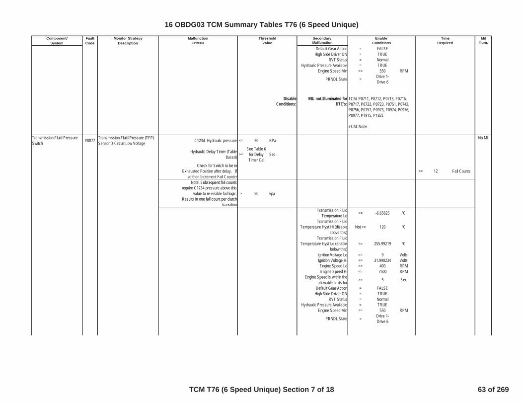
Component/ Fault Monitor Strategy Secondary MilSystem Code Description Malfunction Illum.
Malfunction Threshold Enable TimeCriteria Value Conditions Required
Default Gear Action = FALSEHigh Side Driver ON = TRUE
RVT Status = NormalHydraulic Pressure Available = TRUE
Engine Speed Min >= 550 RPM
PRNDL State = Drive 1-Drive 6
DisableConditions:
MIL not Illuminated forDTC's:
Transmission Fluid PressureSwitch P0877 Transmission Fluid Pressure (TFP)
Sensor D Circuit Low Voltage C1234 Hydraulic pressure <= 50 KPa No Mil
Hydraulic Delay Timer (TableBased) >=
See Table 6for DelayTimer Cal
Sec
Check for Switch to be inExhausted Position after delay, If
so then Increment Fail Counter>= 12 Fail Counts
Note: Subsequent fail countsrequire C1234 pressure above this
value to re-enable fail logic.Results in one fail count per clutch
transition
> 50 kpa
Transmission FluidTemperature Lo >= -6.65625 ºC
Transmission FluidTemperature Hyst Hi (disable
above this)Not >= 120 ºC
Transmission FluidTemperature Hyst Lo (enable
below this)<= 255.99219 ºC
Ignition Voltage Lo >= 9 VoltsIgnition Voltage Hi <= 31.990234 VoltsEngine Speed Lo >= 400 RPMEngine Speed Hi <= 7500 RPM
Engine Speed is within theallowable limits for >= 5 Sec
Default Gear Action = FALSEHigh Side Driver ON = TRUE
RVT Status = NormalHydraulic Pressure Available = TRUE
Engine Speed Min >= 550 RPM
PRNDL State = Drive 1-Drive 6
TCM: P0711, P0712, P0713, P0716,P0717, P0722, P0723, P0751, P0742,P0756, P0757, P0973, P0974, P0976,P0977, P1915, P182E
ECM: None
16 OBDG03 TCM Summary Tables T76 (6 Speed Unique)
TCM T76 (6 Speed Unique) Section 7 of 18 63 of 269

Component/ Fault Monitor Strategy Secondary MilSystem Code Description Malfunction Illum.
Malfunction Threshold Enable TimeCriteria Value Conditions Required
DisableConditions:
MIL not Illuminated forDTC's:
Transmission Fluid PressureSwitch P0878 Transmission Fluid Pressure (TFP)
Sensor D Circuit High Voltage C1234 Hydraulic pressure >= 700 KPa No Mil
Hydraulic Delay Timer (TableBased) >=
See Table 6for DelayTimer Cal
Sec
Check for Switch to be inPressurized Position after delay,If so then Increment Fail Counter
>= 12 Fail Counts
Note: Subsequent fail countsrequire C1234 pressure below this
value to re-enable fail logic.Results in one fail count per clutch
transition
< 700 Kpa
Transmission FluidTemperature Lo >= -6.65625 ºC
Transmission FluidTemperature Hyst Hi (disable
above this)Not >= 120 ºC
Transmission FluidTemperature Hyst Lo (enable
below this)<= 255.99219 ºC
Ignition Voltage Lo >= 9 VoltsIgnition Voltage Hi <= 31.990234 VoltsEngine Speed Lo >= 400 RPMEngine Speed Hi <= 7500 RPM
Engine Speed is within theallowable limits for >= 5 Sec
Default Gear Action = FALSEHigh Side Driver ON = TRUE
RVT Status = NormalHydraulic Pressure Available = TRUE
Engine Speed Min >= 550 RPM
PRNDL State = Drive 1-Drive 6
DisableConditions:
MIL not Illuminated forDTC's:
Variable Bleed Solenoid (VBS) P0965Pressure Control (PC) Solenoid BControl Circuit Rationality Test(C35R VBS)
The HWIO reports an invalidvoltage (out of range) error flag = TRUE Boolean >= 4.4 Fail Time (Sec)
No Mil
outof 5 Sample Time
(Sec)Ignition Voltage >= 9 VoltsIgnition Voltage <= 31.990234 Volts
TCM: P0711, P0712, P0713, P0716,P0717, P0722, P0723, P0751, P0742,P0756, P0757, P0973, P0974, P0976,P0977, P1915, P182E
ECM: None
TCM: P0711, P0712, P0713, P0716,P0717, P0722, P0723, P0751, P0742,P0756, P0757, P0973, P0974, P0976,P0977, P1915, P182E
ECM: None
16 OBDG03 TCM Summary Tables T76 (6 Speed Unique)
TCM T76 (6 Speed Unique) Section 8 of 18 64 of 269

Component/ Fault Monitor Strategy Secondary MilSystem Code Description Malfunction Illum.
Malfunction Threshold Enable TimeCriteria Value Conditions Required
Engine Speed >= 400 RPMEngine Speed <= 7500 RPM
Engine Speed is within theallowable limits for >= 5 Sec
P0965 Status is not =
Test FailedThis Key
On orFaultActive
DisableConditions:
MIL not Illuminated forDTC's:
Variable Bleed Solenoid (VBS) P0969Pressure Control (PC) Solenoid CControl Circuit Rationality Test(C456/CBR1 VBS)
The HWIO reports an invalidvoltage (out of range) error flag = TRUE Boolean >= 4.4 Fail Time (Sec)
No Mil
outof 5 Sample Time
(Sec)
P0969 Status is not =
Test FailedThis Key
On orFaultActive
Ignition Voltage >= 9 VoltsIgnition Voltage <= 31.990234 Volts
Engine Speed >= 400 RPMEngine Speed <= 7500 RPM
Engine Speed is within theallowable limits for >= 5 Sec
DisableConditions:
MIL not Illuminated forDTC's:
Mode 3 Multiplex Valve P0976 Shift Solenoid BControl Circuit Low(Mode 3 Solenoid)
The HWIO reports a low voltage(ground short) error flag = TRUE Boolean >= 1.2 Sec No Mil
outof 1.5 Sec
P0976 Status is not =
Test FailedThis Key
On orFaultActive
Ignition Voltage >= 9 VoltsIgnition Voltage <= 31.990234 Volts
Engine Speed >= 400 RPMEngine Speed <= 7500 RPM
Engine Speed is within theallowable limits for >= 5 Sec
TCM: None
ECM: None
TCM: None
ECM: None
16 OBDG03 TCM Summary Tables T76 (6 Speed Unique)
TCM T76 (6 Speed Unique) Section 9 of 18 65 of 269
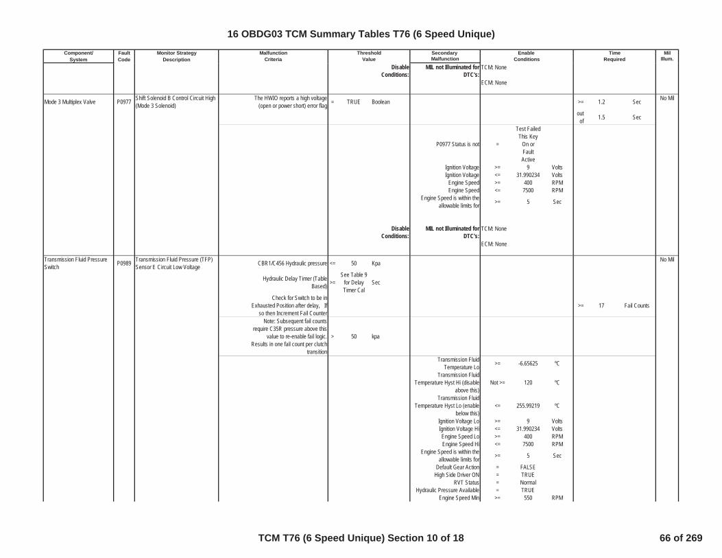
Component/ Fault Monitor Strategy Secondary MilSystem Code Description Malfunction Illum.
Malfunction Threshold Enable TimeCriteria Value Conditions Required
DisableConditions:
MIL not Illuminated forDTC's:
Mode 3 Multiplex Valve P0977 Shift Solenoid B Control Circuit High(Mode 3 Solenoid)
The HWIO reports a high voltage(open or power short) error flag = TRUE Boolean >= 1.2 Sec No Mil
outof 1.5 Sec
P0977 Status is not =
Test FailedThis Key
On orFaultActive
Ignition Voltage >= 9 VoltsIgnition Voltage <= 31.990234 Volts
Engine Speed >= 400 RPMEngine Speed <= 7500 RPM
Engine Speed is within theallowable limits for >= 5 Sec
DisableConditions:
MIL not Illuminated forDTC's:
Transmission Fluid PressureSwitch P0989 Transmission Fluid Pressure (TFP)
Sensor E Circuit Low Voltage CBR1/C456 Hydraulic pressure <= 50 Kpa No Mil
Hydraulic Delay Timer (TableBased) >=
See Table 9for DelayTimer Cal
Sec
Check for Switch to be inExhausted Position after delay, If
so then Increment Fail Counter>= 17 Fail Counts
Note: Subsequent fail countsrequire C35R pressure above this
value to re-enable fail logic.Results in one fail count per clutch
transition
> 50 kpa
Transmission FluidTemperature Lo >= -6.65625 ºC
Transmission FluidTemperature Hyst Hi (disable
above this)Not >= 120 ºC
Transmission FluidTemperature Hyst Lo (enable
below this)<= 255.99219 ºC
Ignition Voltage Lo >= 9 VoltsIgnition Voltage Hi <= 31.990234 VoltsEngine Speed Lo >= 400 RPMEngine Speed Hi <= 7500 RPM
Engine Speed is within theallowable limits for >= 5 Sec
Default Gear Action = FALSEHigh Side Driver ON = TRUE
RVT Status = NormalHydraulic Pressure Available = TRUE
Engine Speed Min >= 550 RPM
TCM: None
ECM: None
TCM: None
ECM: None
16 OBDG03 TCM Summary Tables T76 (6 Speed Unique)
TCM T76 (6 Speed Unique) Section 10 of 18 66 of 269

Component/ Fault Monitor Strategy Secondary MilSystem Code Description Malfunction Illum.
Malfunction Threshold Enable TimeCriteria Value Conditions Required
PRNDL State = Drive 1-Drive 6
DisableConditions:
MIL not Illuminated forDTC's:
Transmission Fluid PressureSwitch P0990 Transmission Fluid Pressure (TFP)
Sensor E Circuit High Voltage CBR1/C456 Hydraulic pressure >= 700 Kpa No Mil
Hydraulic Delay Timer (TableBased) >=
See Table 9for DelayTimer Cal
Sec
Check for Switch to be inPressurized Position after delay, If
so then Increment Fail Counter>= 30 Fail Counts
Note: Subsequent fail countsrequire C35R pressure above this
value to re-enable fail logic.Results in one fail count per clutch
transition
< 700 kpa
Transmission FluidTemperature Lo >= -6.65625 ºC
Transmission FluidTemperature Hyst Hi (disable
above this)Not >= 120 ºC
Transmission FluidTemperature Hyst Lo (enable
below this)<= 255.99219 ºC
Ignition Voltage Lo >= 9 VoltsIgnition Voltage Hi <= 31.990234 VoltsEngine Speed Lo >= 400 RPMEngine Speed Hi <= 7500 RPM
Engine Speed is within theallowable limits for >= 5 Sec
Default Gear Action = FALSEHigh Side Driver ON = TRUE
RVT Status = NormalHydraulic Pressure Available = TRUE
Engine Speed Min >= 550 RPM
PRNDL State = Drive 1-Drive 6
DisableConditions:
MIL not Illuminated forDTC's:
Mode Switch P1762 Transmission Mode Switch SignalCircuit (rolling count)
Rolling count value received fromBCM does not match expected
value= TRUE Boolean >= 3 Fail Counter
No Mil
TCM: P0711, P0712, P0713, P0716,P0717, P0722, P0723, P0751, P0742,P0756, P0757, P0973, P0974, P0976,P0977, P1915, P182E
ECM: None
TCM: P0711, P0712, P0713, P0716,P0717, P0722, P0723, P0751, P0742,P0756, P0757, P0973, P0974, P0976,P0977, P1915, P182E
ECM: None
16 OBDG03 TCM Summary Tables T76 (6 Speed Unique)
TCM T76 (6 Speed Unique) Section 11 of 18 67 of 269
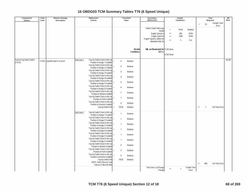
Component/ Fault Monitor Strategy Secondary MilSystem Code Description Malfunction Illum.
Malfunction Threshold Enable TimeCriteria Value Conditions Required
> 10 Sample Timer(Sec)
Pattern Switch MessageHealth = TRUE Boolean
Engine Speed Lo >= 400 RPMEngine Speed Hi <= 7500 RPM
Engine Speed is within theallowable limits for >= 5 Sec
DisableConditions:
MIL not Illuminated forDTC's:
Tap Up Tap Down Switch(TUTD) P1765 Upshift Switch Circuit #2 Fail Case 1 Tap Up Switch Stuck in the Up
Position in Range 1 Enabled = 0 Boolean No Mil
Tap Up Switch Stuck in the UpPosition in Range 2 Enabled = 0 Boolean
Tap Up Switch Stuck in the UpPosition in Range 3 Enabled = 0 Boolean
Tap Up Switch Stuck in the UpPosition in Range 4 Enabled = 0 Boolean
Tap Up Switch Stuck in the UpPosition in Range 5 Enabled = 0 Boolean
Tap Up Switch Stuck in the UpPosition in Range 6 Enabled = 0 Boolean
Tap Up Switch Stuck in the UpPosition in Neutral Enabled = 1 Boolean
Tap Up Switch Stuck in the UpPosition in Park Enabled = 1 Boolean
Tap Up Switch Stuck in the UpPosition in Reverse Enabled = 0 Boolean
Tap Up Switch ON = TRUE Boolean >= 1 Fail Time (Sec)
Fail Case 2 Tap Up Switch Stuck in the UpPosition in Range 1 Enabled = 1 Boolean
Tap Up Switch Stuck in the UpPosition in Range 2 Enabled = 1 Boolean
Tap Up Switch Stuck in the UpPosition in Range 3 Enabled = 1 Boolean
Tap Up Switch Stuck in the UpPosition in Range 4 Enabled = 1 Boolean
Tap Up Switch Stuck in the UpPosition in Range 5 Enabled = 1 Boolean
Tap Up Switch Stuck in the UpPosition in Range 6 Enabled = 1 Boolean
Tap Up Switch Stuck in the UpPosition in Neutral Enabled = 0 Boolean
Tap Up Switch Stuck in the UpPosition in Park Enabled = 0 Boolean
Tap Up Switch Stuck in the UpPosition in Reverse Enabled = 0 Boolean
Tap Up Switch ON = TRUE BooleanNOTE: Both Failcase1 and
Failcase 2 Must Be Met >= 600 Fail Time (Sec)
Time Since Last RangeChange >= 1 Enable Time
(Sec)
TCM: None
ECM: None
16 OBDG03 TCM Summary Tables T76 (6 Speed Unique)
TCM T76 (6 Speed Unique) Section 12 of 18 68 of 269

Component/ Fault Monitor Strategy Secondary MilSystem Code Description Malfunction Illum.
Malfunction Threshold Enable TimeCriteria Value Conditions Required
Ignition Voltage Lo >= 9 VoltsIgnition Voltage Hi <= 31.990234 VoltsEngine Speed Lo >= 400 RPMEngine Speed Hi <= 7500 RPM
Engine Speed is within theallowable limits for >= 5 Sec
P1765 Status is
Test FailedThis Key
On orFaultActive
DisableConditions:
MIL not Illuminated forDTC's:
Tap Up Tap Down Switch(TUTD) P1766 Downshift Switch Circuit #2
Fail Case 1 Tap Down Switch Stuck in theDown Position in Range 1 Enabled = 0 Boolean
No Mil
Tap Down Switch Stuck in theDown Position in Range 2 Enabled = 0 Boolean
Tap Down Switch Stuck in theDown Position in Range 3 Enabled = 0 Boolean
Tap Down Switch Stuck in theDown Position in Range 4 Enabled = 0 Boolean
Tap Down Switch Stuck in theDown Position in Range 5 Enabled = 0 Boolean
Tap Down Switch Stuck in theDown Position in Range 6 Enabled = 0 Boolean
Tap Down Switch Stuck in theDown Position in Range Neutral
Enabled= 1 Boolean
Tap Down Switch Stuck in theDown Position in Range Park
Enabled= 1 Boolean
Tap Down Switch Stuck in theDown Position in Range Reverse
Enabled= 0 Boolean
Tap Down Switch ON = TRUE Boolean >= 1 sec
Fail Case 2 Tap Down Switch Stuck in theDown Position in Range 1 Enabled = 1 Boolean
Tap Down Switch Stuck in theDown Position in Range 2 Enabled = 1 Boolean
Tap Down Switch Stuck in theDown Position in Range 3 Enabled = 1 Boolean
TCM: P1767, P1761, P182E, P1915
ECM: None
16 OBDG03 TCM Summary Tables T76 (6 Speed Unique)
TCM T76 (6 Speed Unique) Section 13 of 18 69 of 269
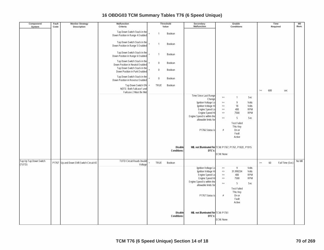
Component/ Fault Monitor Strategy Secondary MilSystem Code Description Malfunction Illum.
Malfunction Threshold Enable TimeCriteria Value Conditions Required
Tap Down Switch Stuck in theDown Position in Range 4 Enabled = 1 Boolean
Tap Down Switch Stuck in theDown Position in Range 5 Enabled = 1 Boolean
Tap Down Switch Stuck in theDown Position in Range 6 Enabled = 1 Boolean
Tap Down Switch Stuck in theDown Position in Neutral Enabled = 0 Boolean
Tap Down Switch Stuck in theDown Position in Park Enabled = 0 Boolean
Tap Down Switch Stuck in theDown Position in Reverse Enabled = 0 Boolean
Tap Down Switch ON = TRUE BooleanNOTE: Both Failcase1 and
Failcase 2 Must Be Met >= 600 sec
Time Since Last RangeChange >= 1 Sec
Ignition Voltage Lo >= 9 VoltsIgnition Voltage Hi <= 18 VoltsEngine Speed Lo >= 400 RPMEngine Speed Hi <= 7500 RPM
Engine Speed is within theallowable limits for >= 5 Sec
P1766 Status is
Test FailedThis Key
On orFaultActive
DisableConditions:
MIL not Illuminated forDTC's:
Tap Up Tap Down Switch(TUTD) P1767 Up and Down Shift Switch Circuit #2 TUTD Circuit Reads Invalid
Voltage = TRUE Boolean >= 60 Fail Time (Sec) No Mil
Ignition Voltage Lo >= 9 VoltsIgnition Voltage Hi <= 31.990234 VoltsEngine Speed Lo >= 400 RPMEngine Speed Hi <= 7500 RPM
Engine Speed is within theallowable limits for >= 5 Sec
P1767 Status is
Test FailedThis Key
On orFaultActive
DisableConditions:
MIL not Illuminated forDTC's:
TCM: P1767, P1761, P182E, P1915
ECM: None
TCM: P1761
ECM: None
16 OBDG03 TCM Summary Tables T76 (6 Speed Unique)
TCM T76 (6 Speed Unique) Section 14 of 18 70 of 269

Component/ Fault Monitor Strategy Secondary MilSystem Code Description Malfunction Illum.
Malfunction Threshold Enable TimeCriteria Value Conditions Required
Tap Up Tap Down Switch(TUTD) P1876 Tap Up and Down Enable Switch
Circuit Current range =Park or
Reverse orNeutral
Range StateSpecialNo MIL
TUTD Enable Switch is Active = TRUE Boolean>= 3 Fail Time (Sec)>= 5 Fail Counts
Ignition Voltage Lo >= 9 VoltsIgnition Voltage Hi <= 31.990234 VoltsVehicle Speed Lo <= 511 KPHEngine Speed Lo >= 400 RPMEngine Speed Hi <= 7500 RPM
Engine Speed is within theallowable limits for >= 5 Sec
P1876 Status is
Test FailedThis Key
On orFaultActive
DisableConditions:
MIL not Illuminated forDTC's:
Transmission Control Module(TCM) P2537 Ignition Switch Accessory Position
Circuit Low TCM Accessory Input = FALSE Boolean < 1 Pass Counts(12.5ms loop)
No Mil
Note: If P2537 has not passed orfailed this key cycle, a pass
counter will be incremented if theAccessory input is TRUE (high).Once the delay time is satisfied,
this pass counter will then beevaluated to determine pass orfail. If the pass criteria has not
been met a fail is reported.
P2537Test PassThis Key
On
P2537Test FailedThis Key
OnPropulsion System Active = TRUE Boolean
Delay timer >= 32 Sec
DisableConditions:
MIL not Illuminated forDTC's:
High Side Driver 2 P2670 Actuator Supply Voltage B CircuitLow
The HWIO reports a low voltage(open or ground short) error flag = TRUE Boolean >= 0 Fail Counts No Mil
outof 0 Sample Counts
TCM: None
ECM: None
TCM: P0815, P0816, P0826, P1761,P1825, P1877, P1915, U0100
ECM: None
16 OBDG03 TCM Summary Tables T76 (6 Speed Unique)
TCM T76 (6 Speed Unique) Section 15 of 18 71 of 269

Component/ Fault Monitor Strategy Secondary MilSystem Code Description Malfunction Illum.
Malfunction Threshold Enable TimeCriteria Value Conditions Required
P2670 Status is not =
Test FailedThis Key
On orFaultActive
High Side Driver 2 On = True Boolean
DisableConditions:
MIL not Illuminated forDTC's:
High Side Driver 2 P2671 Actuator Supply Voltage B CircuitHigh
During the controller power-up,prior to the HSD being turned on,
the HWIO reports that power shortfailure is
= TRUE Boolean >= 0 Fail Counts
No Mil
outof 0 Sample Counts
P2671 Status is not =
Test FailedThis Key
On orFaultActive
DisableConditions:
MIL not Illuminated forDTC's:
Variable Bleed Solenoid (VBS) P2719Pressure Control (PC) Solenoid DControl Circuit Rationality Test(CB26 VBS)
The HWIO reports an invalidvoltage (out of range) error flag = TRUE Boolean >= 4.4 Fail Time (Sec)
No Mil
outof 5 Sample Time
(Sec)
P2719 Status is not =
Test FailedThis Key
On orFaultActive
Ignition Voltage >= 9 VoltsIgnition Voltage <= 31.990234 Volts
Engine Speed >= 400 RPMEngine Speed <= 7500 RPM
Engine Speed is within theallowable limits for >= 5 Sec
DisableConditions:
MIL not Illuminated forDTC's:
Variable Bleed Solenoid (VBS) P2728Pressure Control (PC) Solenoid EControl Circuit Rationality Test(C1234 VBS)
The HWIO reports an invalidvoltage (out of range) error flag = TRUE Boolean >= 4.4 Fail Time (Sec)
No Mil
outof 5 Sample Time
(Sec)
TCM: None
ECM: None
TCM: None
ECM: None
TCM: None
ECM: None
16 OBDG03 TCM Summary Tables T76 (6 Speed Unique)
TCM T76 (6 Speed Unique) Section 16 of 18 72 of 269
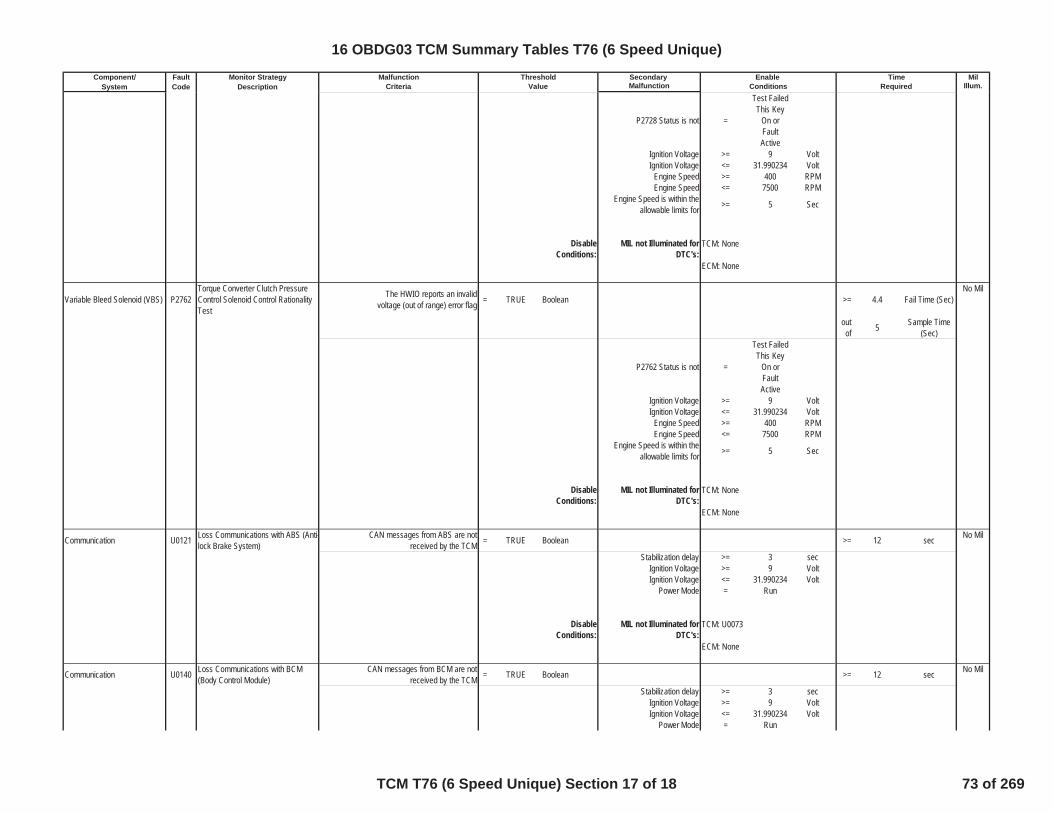
Component/ Fault Monitor Strategy Secondary MilSystem Code Description Malfunction Illum.
Malfunction Threshold Enable TimeCriteria Value Conditions Required
P2728 Status is not =
Test FailedThis Key
On orFaultActive
Ignition Voltage >= 9 VoltIgnition Voltage <= 31.990234 Volt
Engine Speed >= 400 RPMEngine Speed <= 7500 RPM
Engine Speed is within theallowable limits for >= 5 Sec
DisableConditions:
MIL not Illuminated forDTC's:
Variable Bleed Solenoid (VBS) P2762Torque Converter Clutch PressureControl Solenoid Control RationalityTest
The HWIO reports an invalidvoltage (out of range) error flag = TRUE Boolean >= 4.4 Fail Time (Sec)
No Mil
outof 5 Sample Time
(Sec)
P2762 Status is not =
Test FailedThis Key
On orFaultActive
Ignition Voltage >= 9 VoltIgnition Voltage <= 31.990234 Volt
Engine Speed >= 400 RPMEngine Speed <= 7500 RPM
Engine Speed is within theallowable limits for >= 5 Sec
DisableConditions:
MIL not Illuminated forDTC's:
Communication U0121 Loss Communications with ABS (Anti-lock Brake System)
CAN messages from ABS are notreceived by the TCM = TRUE Boolean >= 12 sec No Mil
Stabilization delay >= 3 secIgnition Voltage >= 9 VoltIgnition Voltage <= 31.990234 Volt
Power Mode = Run
DisableConditions:
MIL not Illuminated forDTC's:
Communication U0140 Loss Communications with BCM(Body Control Module)
CAN messages from BCM are notreceived by the TCM = TRUE Boolean >= 12 sec No Mil
Stabilization delay >= 3 secIgnition Voltage >= 9 VoltIgnition Voltage <= 31.990234 Volt
Power Mode = Run
TCM: U0073
ECM: None
TCM: None
ECM: None
TCM: None
ECM: None
16 OBDG03 TCM Summary Tables T76 (6 Speed Unique)
TCM T76 (6 Speed Unique) Section 17 of 18 73 of 269

Component/ Fault Monitor Strategy Secondary MilSystem Code Description Malfunction Illum.
Malfunction Threshold Enable TimeCriteria Value Conditions Required
DisableConditions:
MIL not Illuminated forDTC's:
Communication U0293 Loss Communications with HPCM(Hybrid Powertrain Control Module)
CAN messages from HPCM arenot received by the TCM = TRUE Boolean >= 12 sec No Mil
Stabilization delay >= 3 secIgnition Voltage >= 9 VoltIgnition Voltage <= 31.990234 Volt
Power Mode = Run
TCM: U0073
ECM: None
16 OBDG03 TCM Summary Tables T76 (6 Speed Unique)
TCM T76 (6 Speed Unique) Section 18 of 18 74 of 269

Table 1Axis 0.00 64.00 128.00 192.00 256.00 320.00 384.00 448.00 512.00 N*m
Curve 100.00 120.00 150.00 150.00 150.00 150.00 150.00 150.00 150.00 RPM
Table 2Axis -6.67 -6.66 40.00 ºC
Curve 409.59 2.00 2.00 Sec
Table 3Axis -6.67 -6.66 40.00 ºC
Curve 409.59 3.50 3.50 Sec
Table 4Axis -6.67 -6.66 40.00 ºC
Curve 409.59 2.99 2.00 Sec
Table 5Axis -6.67 -6.66 40.00 ºC
Curve 409.59 3.00 3.00 Sec
Table 6Axis -6.67 -6.66 40.00 80.00 120.00 ºC
Curve 409.00 3.60 1.60 1.40 1.40 Sec
Table 7Axis -6.67 -6.66 40.00 80.00 120.00 ºC
Curve 409.00 3.40 1.40 1.30 1.20 Sec
Table 8Axis -6.67 -6.66 40.00 80.00 120.00 ºC
Curve 409.00 3.60 1.60 1.50 1.40 Sec
16 OBDG03 Diagnostic 2D Tables TCM T76 (6 Speed)
Diagnostic 2D Tables TCM T76 (6 Speed) 1 of 3 75 of 269
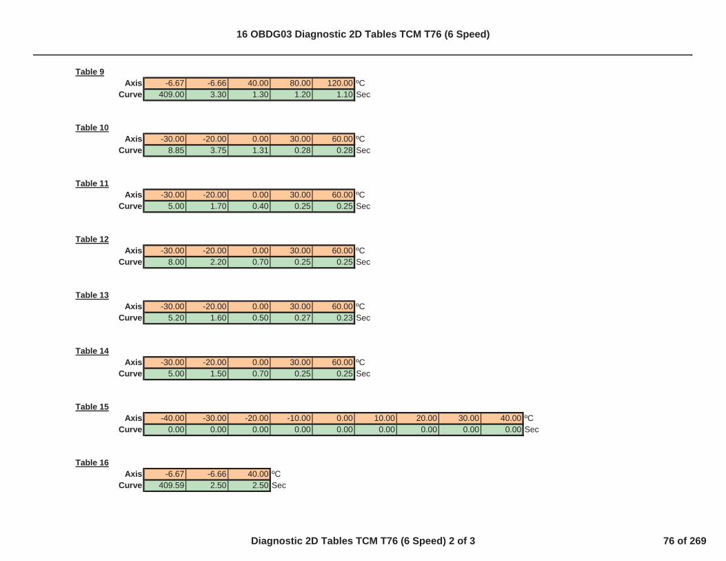
Table 9Axis -6.67 -6.66 40.00 80.00 120.00 ºC
Curve 409.00 3.30 1.30 1.20 1.10 Sec
Table 10Axis -30.00 -20.00 0.00 30.00 60.00 ºC
Curve 8.85 3.75 1.31 0.28 0.28 Sec
Table 11Axis -30.00 -20.00 0.00 30.00 60.00 ºC
Curve 5.00 1.70 0.40 0.25 0.25 Sec
Table 12Axis -30.00 -20.00 0.00 30.00 60.00 ºC
Curve 8.00 2.20 0.70 0.25 0.25 Sec
Table 13Axis -30.00 -20.00 0.00 30.00 60.00 ºC
Curve 5.20 1.60 0.50 0.27 0.23 Sec
Table 14Axis -30.00 -20.00 0.00 30.00 60.00 ºC
Curve 5.00 1.50 0.70 0.25 0.25 Sec
Table 15Axis -40.00 -30.00 -20.00 -10.00 0.00 10.00 20.00 30.00 40.00 ºC
Curve 0.00 0.00 0.00 0.00 0.00 0.00 0.00 0.00 0.00 Sec
Table 16Axis -6.67 -6.66 40.00 ºC
Curve 409.59 2.50 2.50 Sec
16 OBDG03 Diagnostic 2D Tables TCM T76 (6 Speed)
Diagnostic 2D Tables TCM T76 (6 Speed) 2 of 3 76 of 269

Table 17Axis -6.67 -6.66 40.00 ºC
Curve 0.40 0.35 0.30 Sec
Table 18Axis -40.10 -40.00 -20.00 0.00 30.00 60.00 100.00 149.00 149.10 ºC
Curve 256.00 50.00 45.00 40.00 34.00 25.00 20.00 20.00 256.00 ºC
Table 19Axis -40.10 -40.00 -20.00 0.00 30.00 60.00 100.00 149.00 149.10 ºC
Curve 256.00 50.00 45.00 40.00 34.00 25.00 20.00 20.00 256.00 ºC
Table 20Axis -40.10 -40.00 -20.00 0.00 30.00 60.00 100.00 149.00 149.10 ºC
Curve 256.00 10.00 8.00 8.00 8.00 8.00 8.00 8.00 256.00 ºC
Table 21Axis -40.00 -20.00 40.00 ºC
Curve 5.00 3.00 1.00 Sec
Table 22Axis -6.67 -6.66 40.00 ºC
Curve 8191.75 8191.75 8191.75 RPM/Sec
Table 23Axis -6.67 -6.66 40.00 ºC
Curve 8191.75 8191.75 8191.75 RPM/Sec
16 OBDG03 Diagnostic 2D Tables TCM T76 (6 Speed)
Diagnostic 2D Tables TCM T76 (6 Speed) 3 of 3 77 of 269

Component/ Fault Monitor Strategy Secondary MilSystem Code Description Malfunction Illum.
C1253 G Sensor 1.71 G > 5.0 sec SpecialNo MIL
Two fault occurances = TRUEaccumulated or continuous
System Voltage 10 volt32 volt
Vehicle speed 1 kph
Disable Conditions: MIL not Illuminated for DTC's:
C1252 G Sensor -1.71 G > 5.0 sec SpecialNo MIL
Two fault occurances = TRUEaccumulated or continuous
System Voltage 10 volt
32 volt
Vehicle speed 1 kph
Disable Conditions: MIL not Illuminated for DTC's:Longitudinal AccelerationSensor G Sensor variation 0.027 G > 5.0 sec Special
No MIL(Calculated from vehicle speed) Two fault occurances = TRUE
accumulated or continuous
System Voltage > 10 volt32 volt
Stuck at a high OFF > 1.0 sec
Stuck at a low OFF
Absolute of G Sensor Variation 0.011 G
CAN diagnosis OFFDisable Conditions: MIL not Illuminated for DTC's:
ABS(VIGN-VBatt) 3 V > 4 sec One TripPropulsion System Active = TRUE
Starter Motor Engaged = FALSE
Vbatt(PVIGN) >= 5 VRun Crack status = TRUE
Longitudinal Acceleration SensorCircuit Low
TCM: U0073, P175FC1254 Longitudinal Acceleration
Sensor Performance
System Voltage P0561 System Voltage PerformanceDiagnostic
TimeMalfunction Threshold EnableCriteria Value Conditions Required
Longitudinal AccelerationSensor
Longitudinal Acceleration SensorCircuit High
TCM: U0073, P175F
Longitudinal AccelerationSensor
TCM: U0073, P175F
16 OBDG03 TCM Summary Tables T54 (CVT)
TCM T54 (CVT) Section 1 of 20 78 of 269

Component/ Fault Monitor Strategy Secondary MilSystem Code Description Malfunction Illum.
TimeMalfunction Threshold EnableCriteria Value Conditions Required
Disable Conditions: MIL not Illuminated for DTC's:
ROM Diagnosis Result from Operating System = Fail Immediately One Trip
ORFast ROM Diagnosis Result = Fail
from Operation SystemSystem Voltage = from IGN-ON
before Power-Off
RAM Diagnosis Result from Operating System = Fail Immediately One TripOR
Fast RAM Diagnosis Result = Fail
from Operation SystemSystem Voltage = from IGN-ON
before Power-Off
CPU Diagnosis Result from Operating System = Fail Immediately One Trip
ORSemicondutor-Relay Stuck Off Diagnosis Result = Fail
from Operating SystemOR
Semicondutor-Relay Stuck On Diagnosis Result = Failfrom Operating System
System Voltage = from IGN-ONbefore Power-Off
Non-volatile memory (static ordynamic) checksum mismatch = TRUE None One Trip
Disable Conditions: MIL not Illuminated for DTC's: TCM: None
ECM: NoneFail Case 1 The range signal from the TR
switch > 30 Sec One Trip
System voltage >= 10 V
System voltage =< 32 V
Disable Conditions: MIL not Illuminated for DTC's:
TCM: U0100, P0885,P2534 U0073 P0563ECM: None
TCM CPU P0606 CPU Fail
Transmission Control Module(TCM)
P0603 Control Module Long-Term MemoryReset
TCM CPU P0601 ROM Fail
TCM CPU P0604 RAM Fail
A/T Range (TR) Switch P0705 Transmission Range Switch Circuit switch signal is in a "no range signal"state
TCM: NoneECM: None
16 OBDG03 TCM Summary Tables T54 (CVT)
TCM T54 (CVT) Section 2 of 20 79 of 269
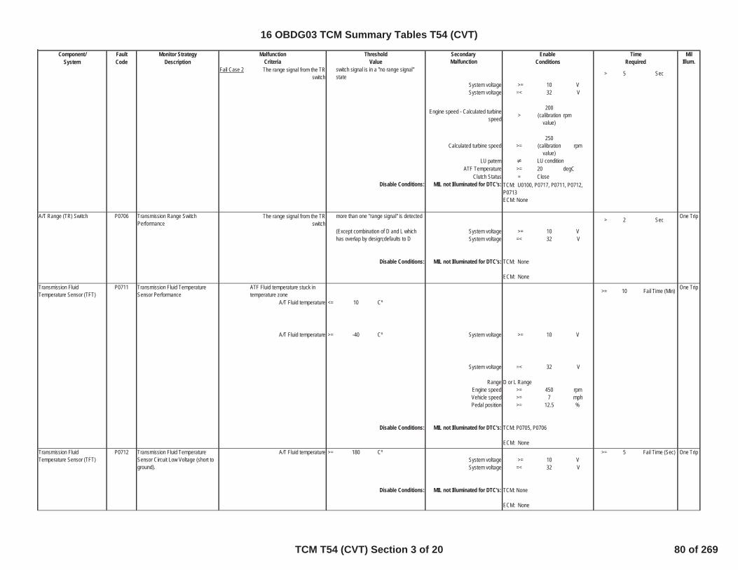
Component/ Fault Monitor Strategy Secondary MilSystem Code Description Malfunction Illum.
TimeMalfunction Threshold EnableCriteria Value Conditions Required
Fail Case 2 The range signal from the TR switch > 5 Sec
System voltage >= 10 VSystem voltage =< 32 V
Engine speed - Calculated turbinespeed >
200(calibration
value)rpm
Calculated turbine speed >=250
(calibrationvalue)
rpm
LU paternATF Temperature >= 20 degC
Clutch Status = CloseDisable Conditions: MIL not Illuminated for DTC's:
The range signal from the TR switch > 2 Sec One Trip
System voltage >= 10 VSystem voltage =< 32 V
Disable Conditions: MIL not Illuminated for DTC's:
ATF Fluid temperature stuck intemperature zone >= 10 Fail Time (Min) One Trip
A/T Fluid temperature <= 10 Cº
A/T Fluid temperature >= -40 Cº System voltage >= 10 V
System voltage =< 32 V
Range D or L RangeEngine speed >= 450 rpmVehicle speed >= 7 mphPedal position >= 12.5 %
Disable Conditions: MIL not Illuminated for DTC's:
A/T Fluid temperature >= 180 Cº >= 5 Fail Time (Sec) One TripSystem voltage >= 10 VSystem voltage =< 32 V
Disable Conditions: MIL not Illuminated for DTC's:
switch signal is in a "no range signal"state
LU condition
TCM: U0100, P0717, P0711, P0712,P0713ECM: None
TCM: None
ECM: None
Transmission FluidTemperature Sensor (TFT)
P0711 Transmission Fluid TemperatureSensor Performance
TCM: P0705, P0706
ECM: None
A/T Range (TR) Switch P0706 Transmission Range SwitchPerformance
more than one "range signal" is detected
(Except combination of D and L whichhas overlap by design;defaults to D
Transmission FluidTemperature Sensor (TFT)
P0712 Transmission Fluid TemperatureSensor Circuit Low Voltage (short toground).
TCM: None
ECM: None
16 OBDG03 TCM Summary Tables T54 (CVT)
TCM T54 (CVT) Section 3 of 20 80 of 269
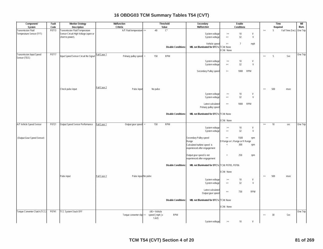
Component/ Fault Monitor Strategy Secondary MilSystem Code Description Malfunction Illum.
TimeMalfunction Threshold EnableCriteria Value Conditions Required
A/T Fluid temperature <= -40 Cº >= 5 Fail Time (Sec) One TripSystem voltage >= 10 VSystem voltage =< 32 V
Vehicle speed >= 7 mphDisable Conditions: MIL not Illuminated for DTC's:
Input Speed Sensor Circuit No Signal Fail Case 1 Primary pulley speed < 150 RPM >= 5 Sec One Trip
System voltage >= 10 VSystem voltage =< 32 V
Secondary Pulley speed >= 1000 RPM
Check pulse input Fail Case 2 Pulse input No pulse >= 500 msec
System voltage >= 10 VSystem voltage =< 32 V
Latest calculated >= 1000 RPMPrimary pulley speed
Disable Conditions: MIL not Illuminated for DTC's:
A/T Vehicle Speed Sensor Output Speed Sensor Performance Fail Case 1 Output gear speed < 150 RPM >= 10 sec One TripSystem voltage >= 10 VSystem voltage =< 32 V
(Output Gear Speed Sensor) Secondary Pulley speed >= 1500 rpmRangeCalculated turbine speed is < 300 rpmexperienced after engagement
Output gear speed is not > 250 rpmexperienced after engagement
Disable Conditions: MIL not Illuminated for DTC's:
Pulse input Fail Case 2 Pulse input >= 500 msecSystem voltage >= 10 VSystem voltage =< 32 V
Latest calculatedOutput gear speed >= 730 RPM
Disable Conditions: MIL not Illuminated for DTC's:
Torque converter slip >=(40 + Vehicle
speed [ mph ] x1.6/2)
RPM >= 30 SecOne Trip
System voltage >= 10 V
Transmission Input SpeedSensor (TISS)
P0717
P0721
D Range or L Range or R Range
TCM: P0705, P0706
ECM: NoneNo pulse
Transmission FluidTemperature Sensor (TFT)
P0713 Transmission Fluid TemperatureSensor Circuit High Voltage (open orshort to power).
TCM: NoneECM: None
TCM: None
ECM: None
TCM: None
ECM: None
Torque Converter Clutch (TCC) P0741 TCC System Stuck OFF
16 OBDG03 TCM Summary Tables T54 (CVT)
TCM T54 (CVT) Section 4 of 20 81 of 269

Component/ Fault Monitor Strategy Secondary MilSystem Code Description Malfunction Illum.
TimeMalfunction Threshold EnableCriteria Value Conditions Required
System voltage =< 32 V
TCC Mode CommandedLock
Lock up command oil pressure > 0.2 MPaDisable Conditions: MIL not Illuminated for DTC's:
The LU coast learning valueCLPrsL ; with A/C OFF
CLPrsLACON ; with A/C ON=< -0.1 MPa
One Trip
System voltage >= 10 V
System voltage =< 32 V
LU coast learning controlTCC Slip < 100 rpm
Engine speed <= 1500 rpmTemperature > 10 degC
< 140 degCTCC Mode
Disable Conditions: MIL not Illuminated for DTC's:
Intermediate Shaft Speed SensorCircuit Performance
Fail Case 1 Secondary pulley speed < 150 RPM > 5 Sec One Trip
System voltage >= 10 V
Check Secondary pulley speed System voltage =< 32 V
Primary pulley speed >= 1000 rpm
Fail Case 2 Check pulse input No pulse > 500 msecSystem voltage >= 10 VSystem voltage =< 32 V
Latest calculated Secondary pulleyspeed >= 1000 rpm
Immediately
Experienced at least once in the same
Commanded Lock
TCM: P2763, P2764, P0741, P0742,P0705, P0706, P0717, P0711, P0712,P0713, P0841, P0842, P0843, P0885,P0961, P0962, P0963, U100
Secondary pulley SpeedSensor
P0792
TCM: P0717
ECM: TBD(engine speed)Torque Converter Clutch (TCC) P0742 TCC System Stuck ON
16 OBDG03 TCM Summary Tables T54 (CVT)
TCM T54 (CVT) Section 5 of 20 82 of 269
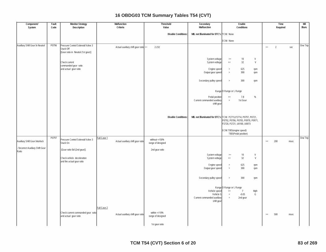
Component/ Fault Monitor Strategy Secondary MilSystem Code Description Malfunction Illum.
TimeMalfunction Threshold EnableCriteria Value Conditions Required
Disable Conditions: MIL not Illuminated for DTC's:
Pressure Control Solenoid Valve 3Stuck Off Actual auxiliary shift gear ratio >= 2.232 >= 2 sec One Trip
[Gear ratio in Neutral (1st gear)]
System voltage >= 10 VCheck current System voltage =< 32 Vcommanded gear ratioand actual gear ratio Engine speed > 625 rpm
Output gear speed > 300 rpm
Secondary pulley speed > 300 rpm
Range
Pedal position >= 7.8 %Current commanded auxiliary = 1st Gear
shift gear
Disable Conditions: MIL not Illuminated for DTC's:
Auxiliary Shift Gear Interlock Pressure Control Solenoid Valve 3Stuck On
Fail Case 1Actual auxiliary shift gear ratio without +/-50%
range of designed >= 200 msecOne Trip
/ Incorrect Auxiliary Shift GearRatio [Gear ratio fail (2nd gear)] 2nd gear ratio
System voltage >= 10 VCheck vehicle deceleration System voltage =< 32 Vand the actual gear ratio
Engine speed > 625 rpmOutput gear speed > 300 rpm
Secondary pulley speed > 300 rpm
RangeVehicle speed >= 7 Mph
Vehicle G < -0.05 GCurrent commanded auxiliary = 2nd gear
shift gear
Check current commanded gear ratioand actual gear ratio
Fail Case 2
Actual auxiliary shift gear ratio within +/-10%range of designed >= 500 msec
1st gear ratio
TCM: None
ECM: None
Auxiliary Shift Gear In Neutral P0796
D Range or L Range
P0797
D Range or L Range
TCM: P2715,P2714, P0797, P0721,P0792, P0706, P0705, P0970, P0971,P2720, P2721, U0100, U0073
ECM: TBD(engine speed) TBD(Pedal position)
16 OBDG03 TCM Summary Tables T54 (CVT)
TCM T54 (CVT) Section 6 of 20 83 of 269
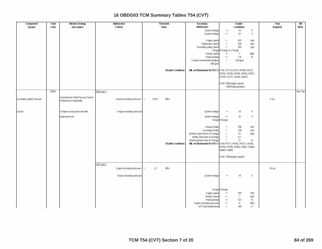
Component/ Fault Monitor Strategy Secondary MilSystem Code Description Malfunction Illum.
TimeMalfunction Threshold EnableCriteria Value Conditions Required
System voltage >= 10 VSystem voltage =< 32 V
Engine speed > 625 rpmOutput gear speed > 300 rpm
Secondary pulley speed > 300 rpmRange
Vehicle speed >= 7 MphPedal position >= 7.8 %
Current commanded auxiliary = 2nd gearshift gear
Disable Conditions: MIL not Illuminated for DTC's:
Secondary pulley Pressure Transmission Fluid Pressure SensorPerformance Rationality
Fail Case 1
Actual secondary pressure - > 0.675 MPa 5 sec
One Trip
Sensor Compare actual pressure with Target secondary pressure System voltage >= 10 V
target pressure System voltage =< 32 VRange D Range
Primary Pulley > 306 rpmSecondary Pulley > 230 rpm
|Vehicle Speed Rate of Change| < 31 mph|Pulley ratio Rate of Change| < 0.1
|Pedal position Rate of Change| < 21 %Disable Conditions: MIL not Illuminated for DTC's:
Fail Case 2Target secondary pressure - > 1.2 MPa 10 sec
Actual secondary pressure System voltage >= 10 V
Range D RangeEngine speed >= 450 rpm
Vehicle Speed >= 7 mphPedal position >= 12.5 %
Target secondary pressure >= 0 MPaA/T Fluid temperature < 180 Cº
P0841
TCM: P0717, P0792, P0721, U0100,P0706, P0705, P0963, P0961, P0842,P0843, P0885
ECM: TBD(engine speed)
D Range or L Range
TCM: P2715,P2714, P0796, P0721,P0792, P0706, P0705, P0970, P0971,P2720, P2721, U0100, U0073
ECM: TBD(engine speed) TBD(Pedal position)
16 OBDG03 TCM Summary Tables T54 (CVT)
TCM T54 (CVT) Section 7 of 20 84 of 269
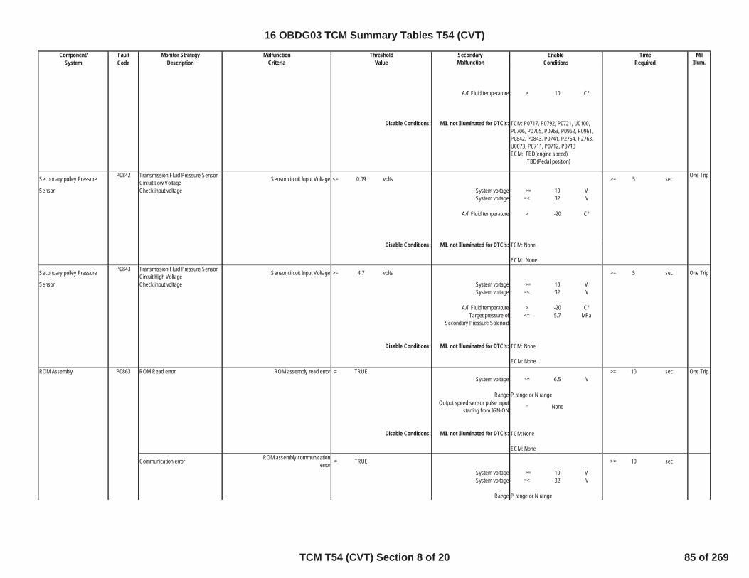
Component/ Fault Monitor Strategy Secondary MilSystem Code Description Malfunction Illum.
TimeMalfunction Threshold EnableCriteria Value Conditions Required
A/T Fluid temperature > 10 Cº
Disable Conditions: MIL not Illuminated for DTC's:
Secondary pulley Pressure Transmission Fluid Pressure SensorCircuit Low Voltage Sensor circuit Input Voltage <= 0.09 volts >= 5 sec One Trip
Sensor Check input voltage System voltage >= 10 VSystem voltage =< 32 V
A/T Fluid temperature > -20 Cº
Disable Conditions: MIL not Illuminated for DTC's:
Secondary pulley Pressure Transmission Fluid Pressure SensorCircuit High Voltage Sensor circuit Input Voltage >= 4.7 volts >= 5 sec One Trip
Sensor Check input voltage System voltage >= 10 VSystem voltage =< 32 V
A/T Fluid temperature > -20 CºTarget pressure of <= 5.7 MPa
Secondary Pressure Solenoid
Disable Conditions: MIL not Illuminated for DTC's:
ROM Assembly ROM Read error ROM assembly read error = TRUE >= 10 sec One TripSystem voltage >= 6.5 V
RangeOutput speed sensor pulse input
starting from IGN-ON = None
Disable Conditions: MIL not Illuminated for DTC's:
Communication error ROM assembly communicationerror = TRUE >= 10 sec
System voltage >= 10 VSystem voltage =< 32 V
Range
TCM: P0717, P0792, P0721, U0100,P0706, P0705, P0963, P0962, P0961,P0842, P0843, P0741, P2764, P2763,U0073, P0711, P0712, P0713ECM: TBD(engine speed) TBD(Pedal position)
P0842
TCM: None
ECM: NoneP0843
TCM: None
ECM: NoneP0863
P range or N range
TCM:None
ECM: None
P range or N range
16 OBDG03 TCM Summary Tables T54 (CVT)
TCM T54 (CVT) Section 8 of 20 85 of 269
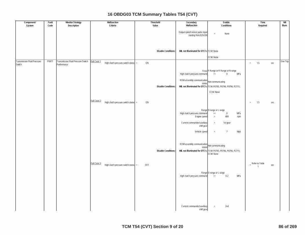
Component/ Fault Monitor Strategy Secondary MilSystem Code Description Malfunction Illum.
TimeMalfunction Threshold EnableCriteria Value Conditions Required
Output speed sensor pulse inputstarting from IGN-ON = None
Disable Conditions: MIL not Illuminated for DTC's:
Transmission Fluid PressureSwitch
Transmission Fluid Pressure SwitchPerformance
Fail Case 1 High clutch pressure switch status = ON > 1.5 sec One Trip
RangeHigh clutch pressure command =< 0 MPa
ROM assembly communicationstatus Not communicating
Disable Conditions: MIL not Illuminated for DTC's:
ECM: None
Fail Case 2 High clutch pressure switch status = ON > 1.5 sec
RangeHigh clutch pressure command =< 0 MPa
Engine speed > 400 rpm
Current commanded auxiliary = 1st gearshift gear
Vehicle speed < 7 Mph
ROM assembly communicationstatus Not communicating
Disable Conditions: MIL not Illuminated for DTC's:
Fail Case 3 High clutch pressure switch status = OFF > Refer to Table1 sec
Range D range or L rangeHigh clutch pressure command >= 0.2 MPa
Current commanded auxiliary = 2ndshift gear
P0871
P Range or R Range or N range
TCM: P0705, P0706, P0796, P2715,
D range or L range
TCM: P0705, P0706, P0796, P2715,ECM: None
TCM: None
ECM: None
16 OBDG03 TCM Summary Tables T54 (CVT)
TCM T54 (CVT) Section 9 of 20 86 of 269

Component/ Fault Monitor Strategy Secondary MilSystem Code Description Malfunction Illum.
TimeMalfunction Threshold EnableCriteria Value Conditions Required
High Clutch pressure solenoidcommand current =< 50 mA
High Clutch pressure solenoidmonitor current =< 60 mA
Engine speed > 550 rpmOutput gear speed > 300 rpm
Secondary pulley speed > 300 rpm
Actual auxiliary shift gear ratio < 1.1
Pedal position >= 7.8 %ROM assembly communication
status Not communicating
MIL not Illuminated for DTC's:ECM: None
Input Voltage Transmission Control Module (TCM)Power Relay Control Circuit Power Source < 8.4 V >= 200 msec One Trip
System voltage > 11 V
Disable Conditions: MIL not Illuminated for DTC's: TCM: None
ECM: None
Line Pressure SolenoidLine Pressure Control Solenoid ValvePerformanceCheck pulley ratio
Fail Case 1 One Trip
(Primary pulley speed /Secondarypulley speed) > 2.55 >= 200 msec
RangeEngine Speed > 600 rpm
Primary pulley speed > 500 rpmKey On timer >= 500 ms
Vehicle G >= -0.051 G
Output speed <= 107 rpm or
Secondary pulley speed > 61 rpmPedal pressed = TRUE
Interval time after 1st detection >= 1 secCheck pulley ratio Fail Case 2
(Primary pulley speed /Secondarypulley speed) > 3.35 >= 100 msec
RangeEngine Speed > 600 rpm
Primary pulley speed
> 500 rpm
TCM: P0705, P0706, P0796, P2715,
P0885
P0961
D Range or L Range or R Range
D Range or L Range or R Range
16 OBDG03 TCM Summary Tables T54 (CVT)
TCM T54 (CVT) Section 10 of 20 87 of 269

Component/ Fault Monitor Strategy Secondary MilSystem Code Description Malfunction Illum.
TimeMalfunction Threshold EnableCriteria Value Conditions Required
Key On timer >= 500 msVehicle G >= -0.051 G
Output speed <= 107 rpm or
Secondary pulley speed > 61 rpmPedal pressed = TRUE
Interval time after 1st detection >= 1 sec
Disable Conditions: MIL not Illuminated for DTC's:
Line Pressure Solenoid Line Pressure Control Solenoid ValveControl Circuit Low Voltage Monitored current <= 200 mA >= 200 msec One Trip
Commanded current >= 750 mA System voltage >= 10 VSystem voltage =< 32 V
Hardware circuitry detects = TRUEshort to ground
Line Pressure Solenoidcommand = ON
Disable Conditions: MIL not Illuminated for DTC's:
Line Pressure Solenoid Line Pressure Control Solenoid ValveControl Circuit High Voltage Monitored current <= 200 mA >= 200 msec One Trip
Commanded current >= 750 mA System voltage >= 10 VSystem voltage =< 32 V
Hardware circuitry detects = FALSEshort to ground
Line Pressure Solenoidcommand = ON
Disable Conditions: MIL not Illuminated for DTC's:
Primary Pressure Solenoid Pressure Control Solenoid Valve 2Performance
Fail Case 1 Pulley ratio (Primary pulley speed/Secondary pulley speed) >= 2.0 and >= 5 Sec One Trip
<= 2.4Range
Engine Speed > 500 rpmTarget pulley ratio < 1.2
Fail Case 2 Pulley ratio (Primary pulley speed/Secondary pulley speed) >= 0.35 and >= 5 Sec
<= 0.75Range
P0962
TCM: P0963ECM: None
P0963
TCM: P0962ECM: None
P0965
D Range or L Range or R Range
D Range or L Range or R Range
TCM: P0717, P0721
ECM: None
16 OBDG03 TCM Summary Tables T54 (CVT)
TCM T54 (CVT) Section 11 of 20 88 of 269
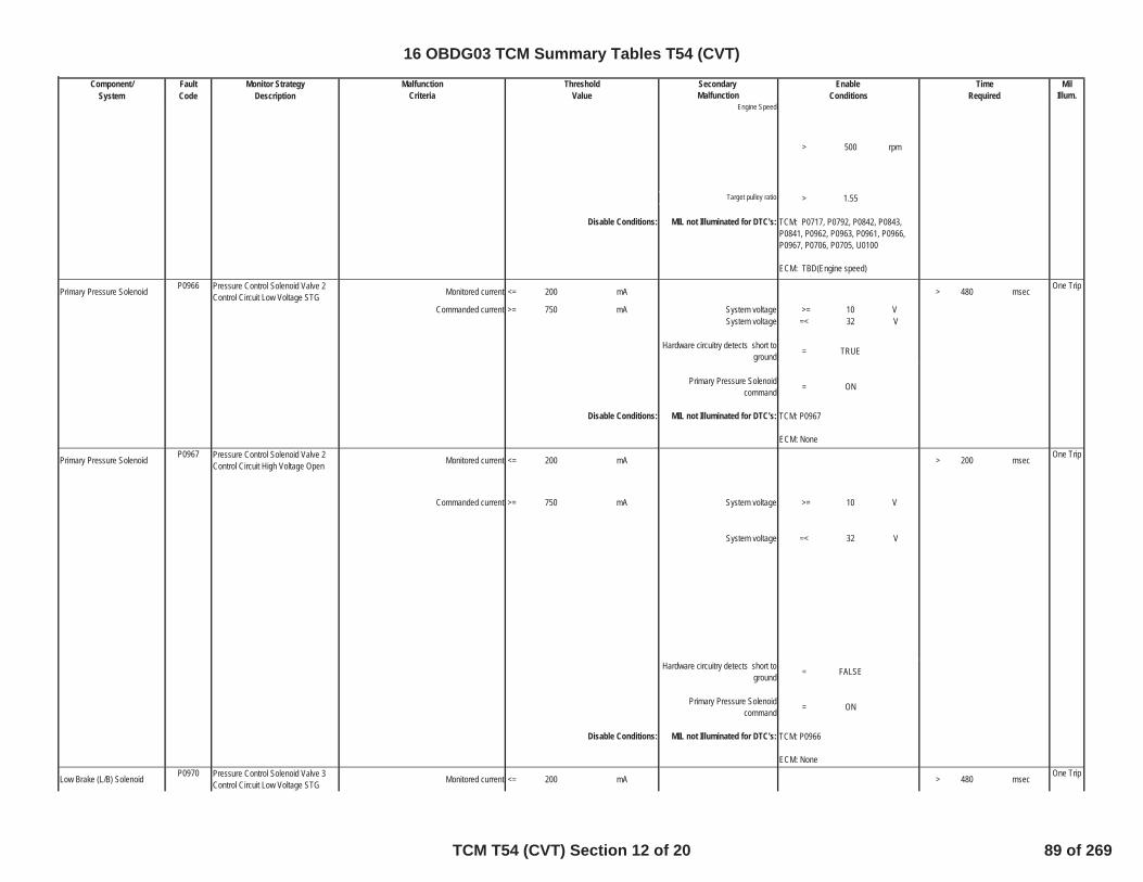
Component/ Fault Monitor Strategy Secondary MilSystem Code Description Malfunction Illum.
TimeMalfunction Threshold EnableCriteria Value Conditions Required
Engine Speed
> 500 rpm
Target pulley ratio > 1.55
Disable Conditions: MIL not Illuminated for DTC's:
Primary Pressure Solenoid Pressure Control Solenoid Valve 2Control Circuit Low Voltage STG Monitored current <= 200 mA > 480 msec One Trip
Commanded current >= 750 mA System voltage >= 10 VSystem voltage =< 32 V
Hardware circuitry detects short toground = TRUE
Primary Pressure Solenoidcommand = ON
Disable Conditions: MIL not Illuminated for DTC's:
Primary Pressure Solenoid Pressure Control Solenoid Valve 2Control Circuit High Voltage Open Monitored current <= 200 mA > 200 msec One Trip
Commanded current >= 750 mA System voltage >= 10 V
System voltage =< 32 V
Hardware circuitry detects short toground = FALSE
Primary Pressure Solenoidcommand = ON
Disable Conditions: MIL not Illuminated for DTC's:
Low Brake (L/B) Solenoid Pressure Control Solenoid Valve 3Control Circuit Low Voltage STG Monitored current <= 200 mA > 480 msec One Trip
TCM: P0717, P0792, P0842, P0843,P0841, P0962, P0963, P0961, P0966,P0967, P0706, P0705, U0100
ECM: TBD(Engine speed)
P0966
TCM: P0967
ECM: NoneP0967
TCM: P0966
ECM: NoneP0970
16 OBDG03 TCM Summary Tables T54 (CVT)
TCM T54 (CVT) Section 12 of 20 89 of 269
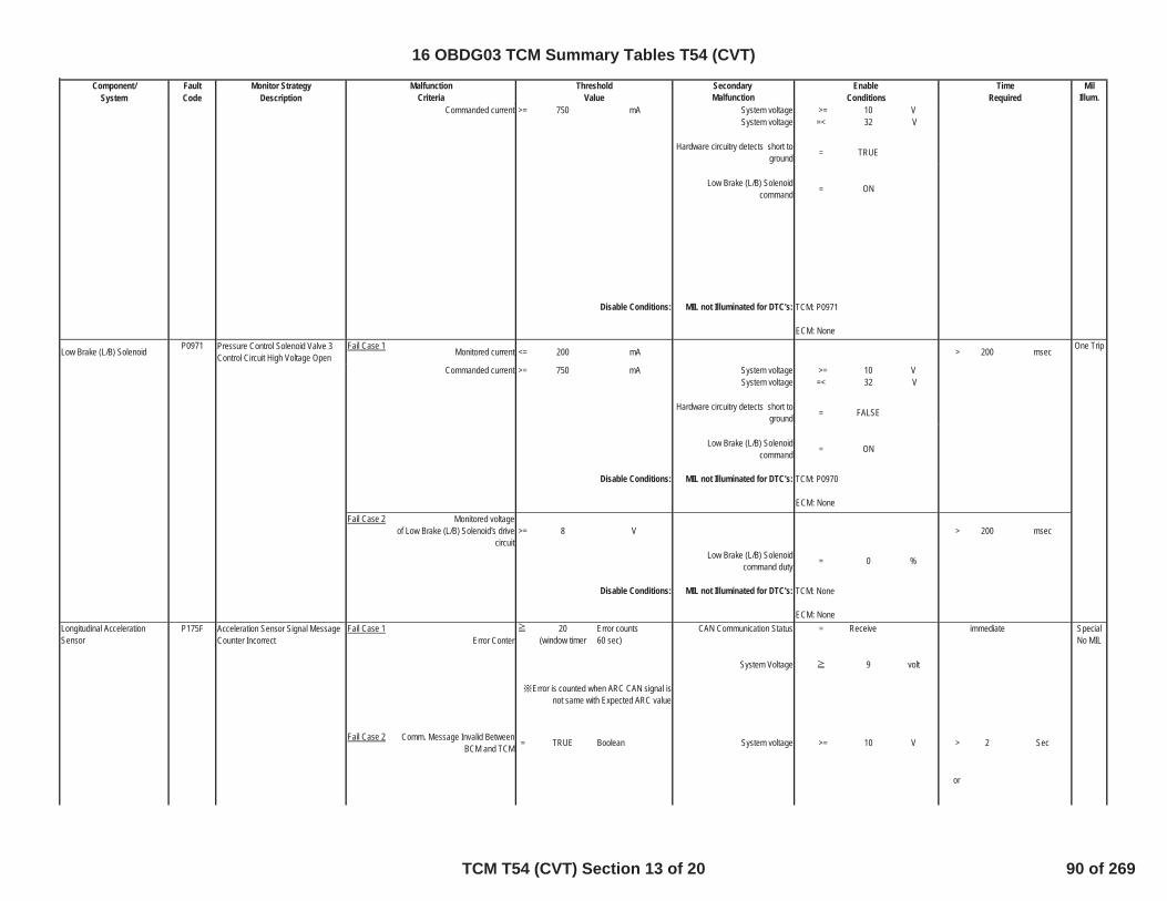
Component/ Fault Monitor Strategy Secondary MilSystem Code Description Malfunction Illum.
TimeMalfunction Threshold EnableCriteria Value Conditions Required
Commanded current >= 750 mA System voltage >= 10 VSystem voltage =< 32 V
Hardware circuitry detects short toground = TRUE
Low Brake (L/B) Solenoidcommand = ON
Disable Conditions: MIL not Illuminated for DTC's:
Low Brake (L/B) Solenoid Pressure Control Solenoid Valve 3Control Circuit High Voltage Open
Fail Case 1 Monitored current <= 200 mA > 200 msec One Trip
Commanded current >= 750 mA System voltage >= 10 VSystem voltage =< 32 V
Hardware circuitry detects short toground = FALSE
Low Brake (L/B) Solenoidcommand = ON
Disable Conditions: MIL not Illuminated for DTC's:
Fail Case 2 Monitored voltageof Low Brake (L/B) Solenoid's drive
circuit>= 8 V > 200 msec
Low Brake (L/B) Solenoidcommand duty = 0 %
Disable Conditions: MIL not Illuminated for DTC's:
Acceleration Sensor Signal MessageCounter Incorrect
Fail Case 1Error Conter
20(window timer
Error counts60 sec)
CAN Communication Status = Receive immediate SpecialNo MIL
System Voltage 9 volt
Fail Case 2 Comm. Message Invalid BetweenBCM and TCM = TRUE Boolean System voltage >= 10 V > 2 Sec
or
Error is counted when ARC CAN signal isnot same with Expected ARC value
TCM: P0971
ECM: None
TCM: None
ECM: None
P0971
TCM: P0970
ECM: None
Longitudinal AccelerationSensor
P175F
16 OBDG03 TCM Summary Tables T54 (CVT)
TCM T54 (CVT) Section 13 of 20 90 of 269

Component/ Fault Monitor Strategy Secondary MilSystem Code Description Malfunction Illum.
TimeMalfunction Threshold EnableCriteria Value Conditions Required
System voltage over Min for > 2 sec > ID Periodic Interval × 5 timesIgnition On for > 2 sec
Engine speed >= 600 rpmCalculated turbine speed >= 600 rpm
Data mismatch Data miss match between ROMassembly data and NVM data = TRUE One Trip
ROM assembly read succeed = TRUEOutput speed sensor pulse input
starting from IGN-ON = None
Disable Conditions: MIL not Illuminated for DTC's:
Internal Control Modul DriverPerformance
Voltage Level Monitor After theSemiconductor Relay
Fail Case 1 Actuator Supply Voltage < 7.55 volt >= 5 sec
One tripPower Source >= 8.4 V
Power Source - Actuator Supply Voltage
=< 3 V
System voltage > 9 VSystem voltage < 32 V
Disable Conditions: MIL not Illuminated for DTC's: TCM: None
ECM: None
Fail Case 2 Fail of Actuator on lower side ofsemi-conductor-Relay
= TRUE Same as Actuator error
Power Source >= 8.4 VPower Source
- Actuator Supply Voltage=< 3 V
System voltage > 9 VSystem voltage < 32 V
Actuator Supply Voltage < 8.4 V
Disable Conditions: MIL not Illuminated for DTC's: TCM: None
ECM: None
ROM Assembly P1790
TCM: None
ECM: NoneP17C9
16 OBDG03 TCM Summary Tables T54 (CVT)
TCM T54 (CVT) Section 14 of 20 91 of 269

Component/ Fault Monitor Strategy Secondary MilSystem Code Description Malfunction Illum.
TimeMalfunction Threshold EnableCriteria Value Conditions Required
System Voltage Ignition voltage Diagnosis(Low) TCM Status = ACC Mode Engine Controller Run Crank = TRUE >= 7 sec One Trip
by ignition switch open circuitTerminal Status for ACC Voltage
Diagnosis
Engine 12 Volt Starter Motor = FALSECommanded On for ACC Voltage
Diagnosis
Propulsion System Active = TRUEfor ACC Voltage Diagnosis
CAN Communication Status = Normalfor ACC Voltage Diagnosis
Auxiliary Shift Gear Interlock Pressure Control (PC) Solenoid 4 -Stuck Off
Fail Case 1Actual auxiliary shift gear ratio outside a +/-50%
range of designed >= 200 msecOne Trip
/ Incorrect Auxiliary Shift GearRatio [Gear ratio fail (1st gear)] 1st gear ratio
System voltage >= 10 VCheck vehicle deceleration and System voltage =< 32 Vthe actual gear ratio
Engine speed > 625 rpmOutput gear speed > 300 rpm
Secondary pulley speed > 300 rpmRange
Vehicle speed >= 7 MphVehicle G < -0.05 G
Current commanded auxiliary = 1st Gearshift gear
Disable Conditions: MIL not Illuminated for DTC's:
Check current commanded gear ratioand actual gear ratio
Fail Case 2Actual auxiliary shift gear ratio within +/-10%
range of designed >= 500 msec
2nd gear ratioSystem voltage >= 10 VSystem voltage =< 32 V
Engine speed > 625 rpmOutput gear speed > 300 rpm
Secondary pulley speed > 300 rpmRange
Vehicle speed >= 7 MphPedal position >= 7.8 %
Current commanded auxiliary = 1st Gearshift gear
P2534
P2714
D Range or L Range
TCM: P2715,P0797, P0796, P0721,P0792, P0706, P0705, P0970, P0971,P2720, P2721, U0100, U0073
ECM: TBD(engine speed) TBD(Pedal position)
D Range or L Range
16 OBDG03 TCM Summary Tables T54 (CVT)
TCM T54 (CVT) Section 15 of 20 92 of 269
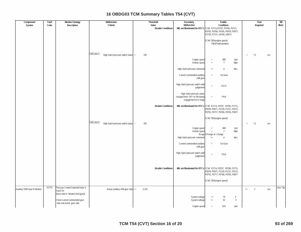
Component/ Fault Monitor Strategy Secondary MilSystem Code Description Malfunction Illum.
TimeMalfunction Threshold EnableCriteria Value Conditions Required
Disable Conditions: MIL not Illuminated for DTC's:
Fail Case 3 High clutch pressure switch status = ON > 1.5 sec
Engine speed > 400 rpmVehicle speed < 7 Mph
High clutch pressure command =< 0 MPa
Current commanded auxiliary = 1st Gearshift gear
High clutch pressure switch validjudgement = FALSE
High clutch pressure statuschanged from OFF to ON during
engagement to D range= TRUE
Disable Conditions: MIL not Illuminated for DTC's:
Fail Case 4 High clutch pressure switch status = ON > 1.5 sec
Engine speed > 400 rpmVehicle speed < 7 Mph
RangeHigh clutch pressure command =< 0 MPa
Current commanded auxiliary = 1st Gearshift gear
High clutch pressure switch validjudgement = TRUE
Disable Conditions: MIL not Illuminated for DTC's:
Auxiliary Shift Gear In Neutral Pressure Control Solenoid Valve 4Stuck On Actual auxiliary shift gear ratio >= 2.232 >= 2 sec One Trip
[Gear ratio in Neutral (2nd gear)]System voltage >= 10 V
Check current commanded gear System voltage =< 32 V ratio and actual gear ratio
Engine speed > 625 rpm
TCM: P2715,P0797, P0796, P0721,P0792, P0706, P0705, P0970, P0971,P2720, P2721, U0100, U0073
ECM: TBD(engine speed) TBD(Pedal position)
TCM: P2714, P0797, P0796, P2715,P0970, P0971, P2720, P2721, P0721,P0792, P0717, P0706, P0705, P0871
ECM: TBD(engine speed)
D Range or L Range
TCM: P2714, P0797, P0796, P2715,P0970, P0971, P2720, P2721, P0721,P0792, P0717, P0706, P0705, P0871
ECM: TBD(engine speed)
P2715
16 OBDG03 TCM Summary Tables T54 (CVT)
TCM T54 (CVT) Section 16 of 20 93 of 269
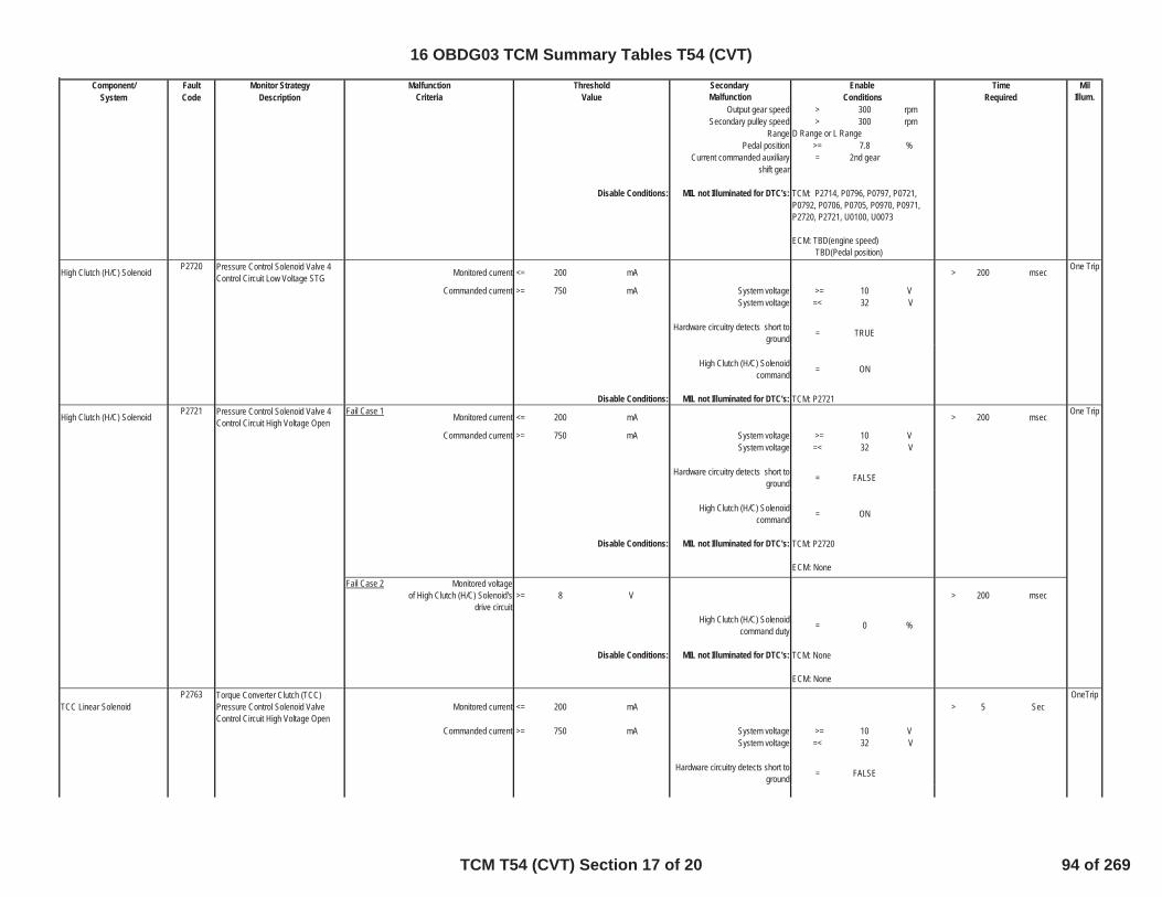
Component/ Fault Monitor Strategy Secondary MilSystem Code Description Malfunction Illum.
TimeMalfunction Threshold EnableCriteria Value Conditions Required
Output gear speed > 300 rpmSecondary pulley speed > 300 rpm
RangePedal position >= 7.8 %
Current commanded auxiliary = 2nd gearshift gear
Disable Conditions: MIL not Illuminated for DTC's:
High Clutch (H/C) Solenoid Pressure Control Solenoid Valve 4Control Circuit Low Voltage STG Monitored current <= 200 mA > 200 msec One Trip
Commanded current >= 750 mA System voltage >= 10 VSystem voltage =< 32 V
Hardware circuitry detects short toground = TRUE
High Clutch (H/C) Solenoidcommand = ON
Disable Conditions: MIL not Illuminated for DTC's:
High Clutch (H/C) Solenoid Pressure Control Solenoid Valve 4Control Circuit High Voltage Open
Fail Case 1 Monitored current <= 200 mA > 200 msec One Trip
Commanded current >= 750 mA System voltage >= 10 VSystem voltage =< 32 V
Hardware circuitry detects short toground = FALSE
High Clutch (H/C) Solenoidcommand = ON
Disable Conditions: MIL not Illuminated for DTC's:
Fail Case 2 Monitored voltageof High Clutch (H/C) Solenoid's
drive circuit>= 8 V > 200 msec
High Clutch (H/C) Solenoidcommand duty = 0 %
Disable Conditions: MIL not Illuminated for DTC's:
TCC Linear SolenoidTorque Converter Clutch (TCC)Pressure Control Solenoid ValveControl Circuit High Voltage Open
Monitored current <= 200 mA > 5 SecOneTrip
Commanded current >= 750 mA System voltage >= 10 VSystem voltage =< 32 V
Hardware circuitry detects short toground = FALSE
P2721
TCM: P2720
ECM: None
TCM: None
ECM: NoneP2763
D Range or L Range
TCM: P2714, P0796, P0797, P0721,P0792, P0706, P0705, P0970, P0971,P2720, P2721, U0100, U0073
ECM: TBD(engine speed) TBD(Pedal position)
P2720
TCM: P2721
16 OBDG03 TCM Summary Tables T54 (CVT)
TCM T54 (CVT) Section 17 of 20 94 of 269

Component/ Fault Monitor Strategy Secondary MilSystem Code Description Malfunction Illum.
TimeMalfunction Threshold EnableCriteria Value Conditions Required
TCC Linear Solenoidcommand = ON
Disable Conditions: MIL not Illuminated for DTC's:
TCC Linear SolenoidTorque Converter Clutch (TCC)Pressure Control Solenoid ValveControl Circuit Low Voltage STG
Monitored current <= 200 mA >= 480 msecOneTrip
Commanded Current >= 750 mA System voltage >= 10 VSystem voltage =< 32 V
Hardware circuitry detects short toground = TRUE
TCC Linear Solenoidcommand = ON
Disable Conditions: MIL not Illuminated for DTC's:
Electric Oil Pump Electric Oil Pump Electrical FailureDuring Being Indicated Driving
Fail Case 1 Monitored State Duty SignalFrom Electril Oil Pump < 46 % > 1.0 sec Special
No MIL
Ignition ON for > 0.36 sec
Input voltage > 10 VInput Voltage over Min for > 0.52 sec
Electric Oil Pumpcommanded ON for > 1.0 sec
Relay commanded = ON
State Signal Frequency > 90 HzState Signal Frequency < 110 Hz
Fail Case 2 Monitored State Duty SignalFrom Electril Oil Pump > 54 % > 1.0 sec
Ignition ON for > 0.36 sec
Input voltage > 10 VInput Voltage over Min for > 0.52 sec
Electric Oil Pumpcommanded ON for > 1.0 sec
Relay commanded = ON
State Signal Frequency > 90 HzState Signal Frequency < 110 Hz
Electric Oil Pump Electrical FailureDuring Being Indicated Stopping
Fail Case 1 Monitored State Duty SignalFrom Electril Oil Pump < 26 % > 1.0 sec
Ignition ON for > 0.36 sec
TCM: P2764
ECM: NoneP2764
TCM: P2763
ECM: NoneP2796
16 OBDG03 TCM Summary Tables T54 (CVT)
TCM T54 (CVT) Section 18 of 20 95 of 269
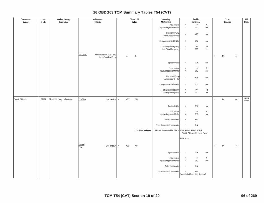
Component/ Fault Monitor Strategy Secondary MilSystem Code Description Malfunction Illum.
TimeMalfunction Threshold EnableCriteria Value Conditions Required
Input voltage > 10 VInput Voltage over Min for > 0.52 sec
Electric Oil Pumpcommanded OFF for > 0.25 sec
Relay commanded ON for > 0.52 sec
State Signal Frequency > 90 HzState Signal Frequency < 110 Hz
Fail Case 2 Monitored State Duty SignalFrom Electril Oil Pump > 34 % > 1.0 sec
Ignition ON for > 0.36 sec
Input voltage > 10 VInput Voltage over Min for > 0.52 sec
Electric Oil Pumpcommanded OFF for > 0.25 sec
Relay commanded ON for > 0.52 sec
State Signal Frequency > 90 HzState Signal Frequency < 110 Hz
Electric Oil Pump P2797 Electric Oil Pump Performance First Time Line pressure < 0.06 Mpa > 1.0 sec SpecialNo MIL
Ignition ON for > 0.36 sec
Input voltage > 10 VInput Voltage over Min for > 0.52 sec
Relay commanded = ON
Start stop control commanded = ON
Disable Conditions: MIL not Illuminated for DTC's:
SecondTime Line pressure < 0.06 Mpa > 1.0 sec
Ignition ON for > 0.36 sec
Input voltage > 10 VInput Voltage over Min for > 0.52 sec
Relay commanded = ON
Start stop control commanded = ON
TCM: P0841, P0842, P0843 Electric Oil Pump Electrical Failure
ECM: None
(on period different from first time)
16 OBDG03 TCM Summary Tables T54 (CVT)
TCM T54 (CVT) Section 19 of 20 96 of 269
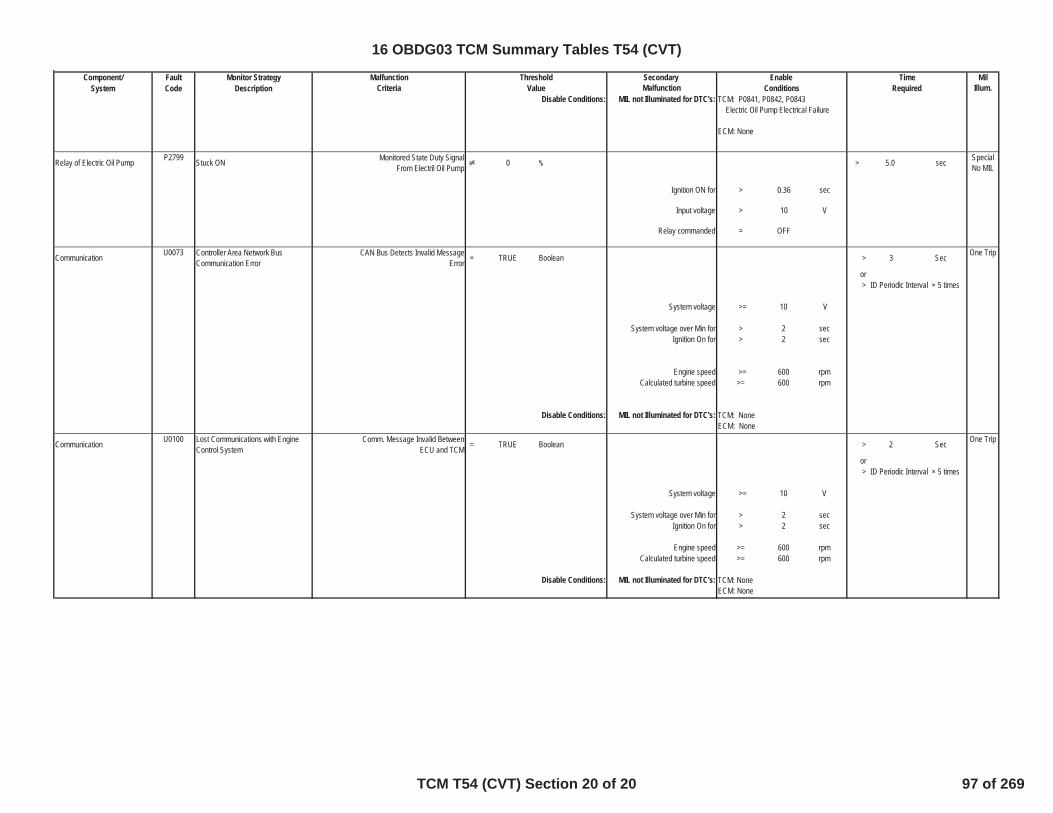
Component/ Fault Monitor Strategy Secondary MilSystem Code Description Malfunction Illum.
TimeMalfunction Threshold EnableCriteria Value Conditions Required
Disable Conditions: MIL not Illuminated for DTC's:
Relay of Electric Oil Pump Stuck ON Monitored State Duty SignalFrom Electril Oil Pump 0 > 5.0 sec Special
No MIL
Ignition ON for > 0.36 sec
Input voltage > 10 V
Relay commanded = OFF
Communication Controller Area Network BusCommunication Error
CAN Bus Detects Invalid MessageError = TRUE Boolean > 3 Sec One Trip
or> ID Periodic Interval × 5 times
System voltage >= 10 V
System voltage over Min for > 2 secIgnition On for > 2 sec
Engine speed >= 600 rpmCalculated turbine speed >= 600 rpm
Disable Conditions: MIL not Illuminated for DTC's:
Communication Lost Communications with EngineControl System
Comm. Message Invalid BetweenECU and TCM = TRUE Boolean > 2 Sec One Trip
or> ID Periodic Interval × 5 times
System voltage >= 10 V
System voltage over Min for > 2 secIgnition On for > 2 sec
Engine speed >= 600 rpmCalculated turbine speed >= 600 rpm
Disable Conditions: MIL not Illuminated for DTC's:
P2799
U0073
TCM: NoneECM: None
U0100
TCM: NoneECM: None
TCM: P0841, P0842, P0843 Electric Oil Pump Electrical Failure
ECM: None
16 OBDG03 TCM Summary Tables T54 (CVT)
TCM T54 (CVT) Section 20 of 20 97 of 269

Table 1 UnitsAxis -55 -20 -19 -10 -9 0 1 40 41 200 Deg C
Curve 10.2 10.2 7.5 7.5 5.5 5.5 3.5 3.5 2.5 2.5 Sec
16 OBDG03 Diagnostic 2D Tables TCM T54 (CVT)
Diagnostic 2D Tables TCM T54 (CVT) 1 of 1 98 of 269

Zone A,B torque limit
Zone C torque limit
16 OBDG03 Diagnostic 3D Tables TCM T54 (CVT)
Diagnostic 3D Tables TCM T54 (CVT) 1 of 1 99 of 269

Component/ Fault Monitor Strategy Secondary MilSystem Code Description Malfunction Illum.
Acceleration Sensor C124FThe lateral accleration signal is stuckat a low magnitude out of rangebecause of a low circuit
Lateral accleration magnitude >= -3.85 g's >= 105 secondsSpecialNo MIL
Lateral accleration magnitude iswithin the range above for >= 120 Sec out
of 120 sample
Lateral accleration magnitude >= -3.85 g'sLateral accleration magnitude
is within the range above for >= 105 Sec
Sensor Type =
VoltageDirectionalProportion
ate
Transmission Type =
Clutch toClutch
Transmission
Lateral acceleration sensorcircuit low diagnostic enable = TRUE Boolean
Battery Voltage <= 31.99902 VoltsBattery Voltage >= 9 Volts
Battery voltage is within theallowable limits for >= 0.1 Sec
Ignition Voltage <= 31.99902 VoltsIgnition Voltage >= 9 Volts
Service Fast Learn (SFL)Mode = FALSE Boolean
Ignition voltage and SFLconditions met for >= 0.1 Sec
DisableConditions:
MIL not Illuminated forDTC's:
Acceleration Sensor C1250The lateral accleration signal is stuckat a high magnitude out of rangebecause of a high circuit
Lateral accleration magnitude >= 3.85 g's >= 105 secondsSpecialNo MIL
Lateral accleration magnitude iswithin the range above for >= 120 Sec out
of 120 sample
Lateral accleration magnitude >= 3.85 g'sLateral accleration magnitude
is within the range above for >= 105 Sec
Sensor Type =
VoltageDirectionalProportion
ate
Transmission Type =
Clutch toClutch
Transmission
Criteria Value Conditions Required
TCM: If calibrated to illuminate the MIL(U0073, U0100)
ECM: None
Malfunction Threshold Enable Time
16 OBDG03 TCM Summary Tables T43 (6 Speed Common)
TCM T43 (6 Speed Common) Section 1 of 61 100 of 269

Component/ Fault Monitor Strategy Secondary MilSystem Code Description Malfunction Illum.Criteria Value Conditions Required
Malfunction Threshold Enable Time
Lateral acceleration sensorcircuit high diagnostic enable = TRUE Boolean
Battery Voltage <= 31.99902 VoltsBattery Voltage >= 9 Volts
Battery voltage is within theallowable limits for >= 0.1 Sec
Ignition Voltage <= 31.99902 VoltsIgnition Voltage >= 9 Volts
Service Fast Learn (SFL)Mode = FALSE Boolean
Ignition voltage and SFLconditions met for >= 0.1 Sec
DisableConditions:
MIL not Illuminated forDTC's:
Acceleration Sensor C1251 The lateral accleration signal is stuckat a high magnitude in range Lateral accleration magnitude <= 3.85 g's Special
No MILLateral accleration magnitude >= 0.53 g's
Lateral accleration magnitude iswithin the range above for >= 120 Sec
Lateral accleration magnitude <= 3.85 g'sLateral accleration magnitude >= 0.53 g'sLateral accleration magnitude
is within the range above for >= 90 Sec
Diagnostic shifting overridecommand = FALSE Boolean
Attained Gear State =1st
through6th
Attained Gear Slip <= 100 RPM
Transmission Type =
Clutch toClutch
Transmission
High Side Driver 1 On = TRUE BooleanVehicle Speed >= 15 kph
Lateral acceleration stuck inrange diagnostic enable = TRUE Boolean
Battery Voltage <= 31.99902 VoltsBattery Voltage >= 9 Volts
Battery voltage is within theallowable limits for >= 0.1 Sec
Ignition Voltage <= 31.99902 VoltsIgnition Voltage >= 9 Volts
Service Fast Learn (SFL)Mode = FALSE Boolean
Ignition voltage and SFLconditions met for >= 0.1 Sec
TCM: If calibrated to illuminate the MIL(U0073, U0100)
ECM: None
16 OBDG03 TCM Summary Tables T43 (6 Speed Common)
TCM T43 (6 Speed Common) Section 2 of 61 101 of 269

Component/ Fault Monitor Strategy Secondary MilSystem Code Description Malfunction Illum.Criteria Value Conditions Required
Malfunction Threshold Enable Time
DisableConditions:
MIL not Illuminated forDTC's:
Transmission Control Module(TCM) P0601 Transmission Electro-Hydraulic
Control Module Read Only MemoryIncorrect program/calibrations
checksum = TRUE Boolean >= 5 Fail Counts One Trip
DisableConditions:
MIL not Illuminated forDTC's:
Transmission Control Module(TCM) P0603
Transmission Electro-HydraulicControl Module Long-Term MemoryReset
Non-volatile memory (static ordynamic) checksum failure at
Powerup= TRUE Boolean Runs
Continously
One Trip
DisableConditions:
MIL not Illuminated forDTC's:
Transmission Control Module(TCM) P0604
Transmission Electro-HydraulicControl Module Random AccessMemory
RAM Read/Write Failure (SingleWord) = TRUE Boolean >= 5 Fail Counts
One Trip
= 16 Sample Counts
DisableConditions:
MIL not Illuminated forDTC's:
Transmission Control Module(TCM) P062F
Transmission Electro-HydraulicControl Module Long Term MemoryPerformance
TCM Non-Volatile Memory bitIncorrect flag at Powerdown = TRUE Boolean Runs
Continously
One Trip
DisableConditions:
MIL not Illuminated forDTC's:
Transmission Control Module(TCM) P0634
Transmission Electro-HydraulicControl Module Internal TemperatureToo High
Fail Case 1Substrate Temperature >= 142.1016 ºC >= 5 Fail Time (Sec)
One Trip
Fail Case 2 Substrate Temperature >= 50 ºC >= 2 Fail Time (Sec)Ignition Voltage >= 18 Volts
Note: either fail case can set theDTC
Ignition Voltage Lo >= 8.59961 VoltsIgnition Voltage Hi <= 31.99902 Volts
Substrate Temp Lo >= 0 ºCSubstrate Temp Hi <= 170 ºC
Substrate Temp BetweenTemp Range for Time >= 0.25 Sec
TCM: If calibrated to illuminate the MIL(P0716, P0717, P0721, P0722, P0723,P07BF, P07C0, P077B, P077C, P077D,P215C, U0073)
ECM: None
TCM: P0601
ECM: None
TCM: P0603
ECM: None
TCM: P0604
ECM: None
TCM: P062F
ECM: None
16 OBDG03 TCM Summary Tables T43 (6 Speed Common)
TCM T43 (6 Speed Common) Section 3 of 61 102 of 269
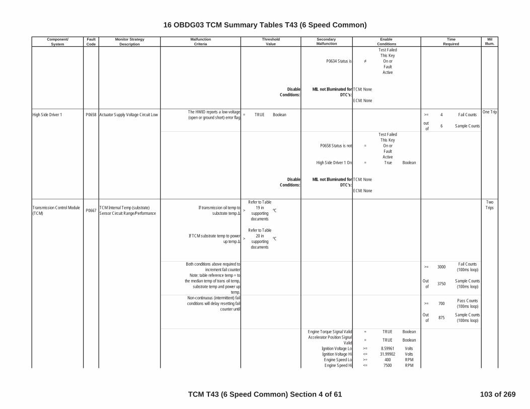
Component/ Fault Monitor Strategy Secondary MilSystem Code Description Malfunction Illum.Criteria Value Conditions Required
Malfunction Threshold Enable Time
P0634 Status is
Test FailedThis Key
On orFaultActive
DisableConditions:
MIL not Illuminated forDTC's:
High Side Driver 1 P0658 Actuator Supply Voltage Circuit Low The HWIO reports a low voltage(open or ground short) error flag = TRUE Boolean >= 4 Fail Counts One Trip
outof 6 Sample Counts
P0658 Status is not =
Test FailedThis Key
On orFaultActive
High Side Driver 1 On = True Boolean
DisableConditions:
MIL not Illuminated forDTC's:
Transmission Control Module(TCM) P0667 TCM Internal Temp (substrate)
Sensor Circuit Range/PerformanceIf transmission oil temp to
substrate temp >
Refer to Table19 in
supportingdocuments
ºC
TwoTrips
If TCM substrate temp to powerup temp >
Refer to Table20 in
supportingdocuments
ºC
Both conditions above required toincrement fail counter >= 3000 Fail Counts
(100ms loop)Note: table reference temp = to
the median temp of trans oil temp,substrate temp and power up
temp.
Outof 3750 Sample Counts
(100ms loop)
Non-continuous (intermittent) failconditions will delay resetting fail
counter until>= 700 Pass Counts
(100ms loop)
Outof 875 Sample Counts
(100ms loop)
Engine Torque Signal Valid = TRUE BooleanAccelerator Position Signal
Valid = TRUE Boolean
Ignition Voltage Lo >= 8.59961 VoltsIgnition Voltage Hi <= 31.99902 VoltsEngine Speed Lo >= 400 RPMEngine Speed Hi <= 7500 RPM
TCM: None
ECM: None
TCM: None
ECM: None
16 OBDG03 TCM Summary Tables T43 (6 Speed Common)
TCM T43 (6 Speed Common) Section 4 of 61 103 of 269

Component/ Fault Monitor Strategy Secondary MilSystem Code Description Malfunction Illum.Criteria Value Conditions Required
Malfunction Threshold Enable Time
Engine Speed is within theallowable limits for >= 5 Sec
Brake torque active = FALSEBelow describes the brake
torque entry criteriaEngine Torque >= 90 N*m
Throttle >= 30.0003 PctTransmission Input Speed <= 200 RPM
Vehicle Speed <= 8 KphTransmission Range ParkTransmission Range Neutral
PTO = Not ActiveSet Brake Torque Active
TRUE if above conditions aremet for:
>= 7 sec
Below describes the braketorque exit criteria
Brake torque entry criteria = Not Met
Clutch hydraulic pressure
ClutchHydraulicAir Purge
Event
Clutch used to exit braketorque active =
CeTFTD_e_C3_RatlE
nblThe above clutch pressure isgreater than this value for one
loop>= 600 kpa
Set Brake Torque ActiveFALSE if above conditions are
met for:>= 20 Sec
P0667 Status is
Test FailedThis Key
On orFaultActive
DisableConditions:
MIL not Illuminated forDTC's:
Transmission Control Module(TCM) P0668 TCM internal temperature (substrate)
thermistor failed at a low voltge Type of Sensor Used =CeTFTI_e_VoltageDirectPro
p
TwoTrips
TCM: P0658, P0668, P0669, P06AD,P06AE, P0716, P0712, P0713, P0717,P0722, P0723, P0962, P0963, P0966,P0967, P0970, P0971, P215C, P2720,P2721, P2729, P2730
ECM: P0101, P0102, P0103, P0106,P0107, P0108, P0171, P0172, P0174,P0175, P0201, P0202, P0203, P0204,P0205, P0206, P0207, P0208, P0300,P0301, P0302, P0303, P0304, P0305,P0306, P0307, P0308, P0401, P042E
16 OBDG03 TCM Summary Tables T43 (6 Speed Common)
TCM T43 (6 Speed Common) Section 5 of 61 104 of 269

Component/ Fault Monitor Strategy Secondary MilSystem Code Description Malfunction Illum.Criteria Value Conditions Required
Malfunction Threshold Enable Time
If TCM Substrate TemperatureSensor = Direct Proportional and
Temp<= -249 ºC
If TCM Substrate TemperatureSensor = Indirect Proportional and
Temp>= -249 ºC
Either condition above will satisfythe fail conditions >= 60 Fail Timer (Sec)
Ignition Voltage Lo >= 8.59961 VoltsIgnition Voltage Hi <= 31.99902 VoltsEngine Speed Lo >= 400 RPMEngine Speed Hi <= 7500 RPM
Engine Speed is within theallowable limits for >= 5 Sec
P0668 Status is
Test FailedThis Key
On orFaultActive
DisableConditions:
MIL not Illuminated forDTC's:
Transmission Control Module(TCM) P0669 TCM internal temperature (substrate)
thermistor failed at a high voltage Type of Sensor Used =CeTFTI_e_VoltageDirectPro
p
TwoTrips
If TCM Substrate TemperatureSensor = Direct Proportional and
Temp>= 249 ºC
If TCM Substrate TemperatureSensor = Indirect Proportional and
Temp<= 249 ºC
Either condition above will satisfythe fail conditions >= 60 Fail Timer (Sec)
Ignition Voltage Lo >= 8.59961 VoltsIgnition Voltage Hi <= 31.99902 VoltsEngine Speed Lo >= 400 RPMEngine Speed Hi <= 7500 RPM
Engine Speed is within theallowable limits for >= 5 Sec
P0669 Status is
Test FailedThis Key
On orFaultActive
For Hybrids, below conditionsmust also be met
Estimated Motor Power Loss >= 0 kWEstimated Motor Power Loss
greater than limit for time >= 0 Sec
Lost Communication withHybrid Processor Control
Module= FALSE
Estimated Motor Power LossFault = FALSE
TCM: None
ECM: None
16 OBDG03 TCM Summary Tables T43 (6 Speed Common)
TCM T43 (6 Speed Common) Section 6 of 61 105 of 269
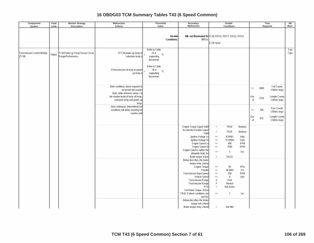
Component/ Fault Monitor Strategy Secondary MilSystem Code Description Malfunction Illum.Criteria Value Conditions Required
Malfunction Threshold Enable Time
DisableConditions:
MIL not Illuminated forDTC's:
Transmission Control Module(TCM) P06AC TCM Power-up Temp Sensor Circuit
Range/PerformanceIf TCM power-up temp to
substrate temp >
Refer to Table20 in
supportingdocuments
ºC
TwoTrips
If transmission oil temp to powerup temp >
Refer to Table18 in
supportingdocuments
ºC
Both conditions above required toincrement fail counter >= 3000 Fail Counts
(100ms loop)Note: table reference temp = to
the median temp of trans oil temp,substrate temp and power up
temp.
Outof 3750 Sample Counts
(100ms loop)
Non-continuous (intermittent) failconditions will delay resetting fail
counter until>= 700 Pass Counts
(100ms loop)
Outof 875 Sample Counts
(100ms loop)
Engine Torque Signal Valid = TRUE BooleanAccelerator Position Signal
Valid = TRUE Boolean
Ignition Voltage Lo >= 8.59961 VoltsIgnition Voltage Hi <= 31.99902 VoltsEngine Speed Lo >= 400 RPMEngine Speed Hi <= 7500 RPM
Engine Speed is within theallowable limits for >= 5 Sec
Brake torque active = FALSEBelow describes the brake
torque entry criteriaEngine Torque >= 90 N*m
Throttle >= 30.0003 PctTransmission Input Speed <= 200 RPM
Vehicle Speed <= 8 KphTransmission Range ParkTransmission Range Neutral
PTO = Not ActiveSet Brake Torque Active
TRUE if above conditions aremet for:
>= 7 sec
Below describes the braketorque exit criteria
Brake torque entry criteria = Not Met
TCM: P0716, P0717, P0722, P0723
ECM: None
16 OBDG03 TCM Summary Tables T43 (6 Speed Common)
TCM T43 (6 Speed Common) Section 7 of 61 106 of 269
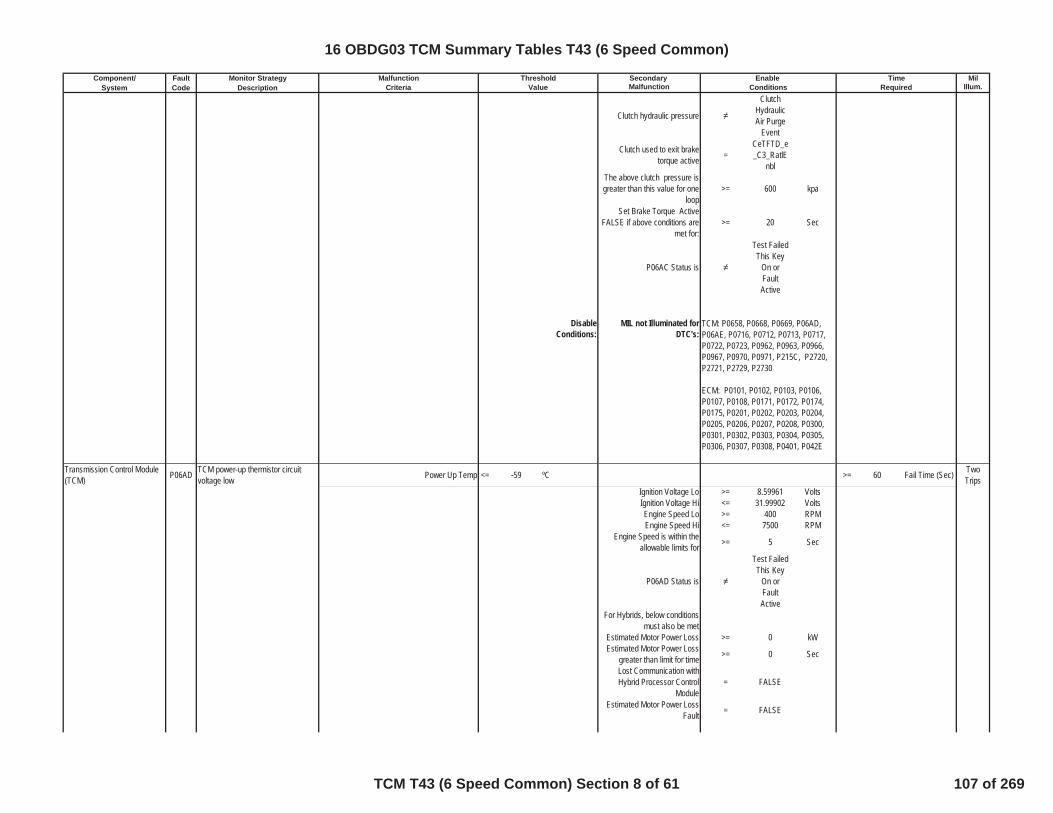
Component/ Fault Monitor Strategy Secondary MilSystem Code Description Malfunction Illum.Criteria Value Conditions Required
Malfunction Threshold Enable Time
Clutch hydraulic pressure
ClutchHydraulicAir Purge
Event
Clutch used to exit braketorque active =
CeTFTD_e_C3_RatlE
nblThe above clutch pressure isgreater than this value for one
loop>= 600 kpa
Set Brake Torque ActiveFALSE if above conditions are
met for:>= 20 Sec
P06AC Status is
Test FailedThis Key
On orFaultActive
DisableConditions:
MIL not Illuminated forDTC's:
Transmission Control Module(TCM) P06AD TCM power-up thermistor circuit
voltage low Power Up Temp <= -59 ºC >= 60 Fail Time (Sec) TwoTrips
Ignition Voltage Lo >= 8.59961 VoltsIgnition Voltage Hi <= 31.99902 VoltsEngine Speed Lo >= 400 RPMEngine Speed Hi <= 7500 RPM
Engine Speed is within theallowable limits for >= 5 Sec
P06AD Status is
Test FailedThis Key
On orFaultActive
For Hybrids, below conditionsmust also be met
Estimated Motor Power Loss >= 0 kWEstimated Motor Power Loss
greater than limit for time >= 0 Sec
Lost Communication withHybrid Processor Control
Module= FALSE
Estimated Motor Power LossFault = FALSE
TCM: P0658, P0668, P0669, P06AD,P06AE, P0716, P0712, P0713, P0717,P0722, P0723, P0962, P0963, P0966,P0967, P0970, P0971, P215C, P2720,P2721, P2729, P2730
ECM: P0101, P0102, P0103, P0106,P0107, P0108, P0171, P0172, P0174,P0175, P0201, P0202, P0203, P0204,P0205, P0206, P0207, P0208, P0300,P0301, P0302, P0303, P0304, P0305,P0306, P0307, P0308, P0401, P042E
16 OBDG03 TCM Summary Tables T43 (6 Speed Common)
TCM T43 (6 Speed Common) Section 8 of 61 107 of 269

Component/ Fault Monitor Strategy Secondary MilSystem Code Description Malfunction Illum.Criteria Value Conditions Required
Malfunction Threshold Enable Time
DisableConditions:
MIL not Illuminated forDTC's:
Transmission Control Module(TCM) P06AE TCM power-up thermistor circuit
voltage high Power Up Temp >= 164 ºC >= 60 Fail Time (Sec) TwoTrips
Ignition Voltage Lo >= 8.59961 VoltsIgnition Voltage Hi <= 31.99902 VoltsEngine Speed Lo >= 400 RPMEngine Speed Hi <= 7500 RPM
Engine Speed is within theallowable limits for >= 5 Sec
P06AE Status is
Test FailedThis Key
On orFaultActive
DisableConditions:
MIL not Illuminated forDTC's:
Transmission FluidTemperature Sensor (TFT) P0711 Trans Fluid Temp Sensor Circuit
Range/PerformanceIf transmission oil temp to
substrate temp >
Refer to Table19 in
supportingdocuments
ºC
TwoTrips
If transmission oil temp to powerup temp >
Refer to Table18 in
supportingdocuments
ºC
Both conditions above required toincrement fail counter >= 3000 Fail Counts
(100ms loop)Note: table reference temp = to
the median temp of trans oil temp,substrate temp and power up
temp.
Outof 3750 Sample Counts
(100ms loop)
Non-continuous (intermittent) failconditions will delay resetting fail
counter until>= 700 Pass Counts
(100ms loop)
Outof 875 Sample Counts
(100ms loop)
Engine Torque Signal Valid = TRUE BooleanAccelerator Position Signal
Valid = TRUE Boolean
Ignition Voltage Lo >= 8.59961 VoltsIgnition Voltage Hi <= 31.99902 VoltsEngine Speed Lo >= 400 RPMEngine Speed Hi <= 7500 RPM
Engine Speed is within theallowable limits for >= 5 Sec
Brake torque active = FALSE
TCM: P0716, P0717, P0722, P0723
ECM: None
TCM: None
ECM: None
16 OBDG03 TCM Summary Tables T43 (6 Speed Common)
TCM T43 (6 Speed Common) Section 9 of 61 108 of 269

Component/ Fault Monitor Strategy Secondary MilSystem Code Description Malfunction Illum.Criteria Value Conditions Required
Malfunction Threshold Enable Time
Below describes the braketorque entry criteria
Engine Torque >= 90 N*mThrottle >= 30.0003 Pct
Transmission Input Speed <= 200 RPMVehicle Speed <= 8 Kph
Transmission Range ParkTransmission Range Neutral
PTO = Not ActiveSet Brake Torque Active
TRUE if above conditions aremet for:
>= 7 sec
Below describes the braketorque exit criteria
Brake torque entry criteria = Not Met
Clutch hydraulic pressure
ClutchHydraulicAir Purge
Event
Clutch used to exit braketorque active =
CeTFTD_e_C3_RatlE
nblThe above clutch pressure isgreater than this value for one
loop>= 600 kpa
Set Brake Torque ActiveFALSE if above conditions are
met for:>= 20 Sec
P0711 Status is
Test FailedThis Key
On orFaultActive
DisableConditions:
MIL not Illuminated forDTC's:
Transmission FluidTemperature Sensor (TFT) P0712 Transmission fluid temperature
thermistor failed at a low voltage Type of Sensor Used =CeTFTI_e_VoltageDirectPro
p
TwoTrips
If Transmission Fluid TemperatureSensor = Direct Proportional and
Temp<= -74 ºC
If Transmission Fluid TemperatureSensor = Indirect Proportional and
Temp>= -74 ºC
TCM: P0658, P0668, P0669, P06AD,P06AE, P0716, P0712, P0713, P0717,P0722, P0723, P0962, P0963, P0966,P0967, P0970, P0971, P215C, P2720,P2721, P2729, P2730
ECM: P0101, P0102, P0103, P0106,P0107, P0108, P0171, P0172, P0174,P0175, P0201, P0202, P0203, P0204,P0205, P0206, P0207, P0208, P0300,P0301, P0302, P0303, P0304, P0305,P0306, P0307, P0308, P0401, P042E
16 OBDG03 TCM Summary Tables T43 (6 Speed Common)
TCM T43 (6 Speed Common) Section 10 of 61 109 of 269
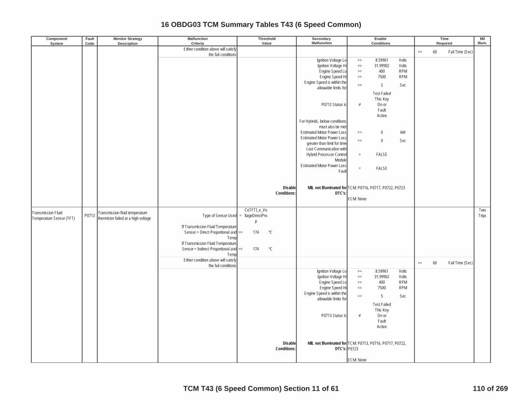
Component/ Fault Monitor Strategy Secondary MilSystem Code Description Malfunction Illum.Criteria Value Conditions Required
Malfunction Threshold Enable Time
Either condition above will satisfythe fail conditions >= 60 Fail Time (Sec)
Ignition Voltage Lo >= 8.59961 VoltsIgnition Voltage Hi <= 31.99902 VoltsEngine Speed Lo >= 400 RPMEngine Speed Hi <= 7500 RPM
Engine Speed is within theallowable limits for >= 5 Sec
P0712 Status is
Test FailedThis Key
On orFaultActive
For Hybrids, below conditionsmust also be met
Estimated Motor Power Loss >= 0 kWEstimated Motor Power Loss
greater than limit for time >= 0 Sec
Lost Communication withHybrid Processor Control
Module= FALSE
Estimated Motor Power LossFault = FALSE
DisableConditions:
MIL not Illuminated forDTC's:
Transmission FluidTemperature Sensor (TFT) P0713 Transmission fluid temperature
thermistor failed at a high voltage Type of Sensor Used =CeTFTI_e_VoltageDirectPro
p
TwoTrips
If Transmission Fluid TemperatureSensor = Direct Proportional and
Temp>= 174 ºC
If Transmission Fluid TemperatureSensor = Indirect Proportional and
Temp<= 174 ºC
Either condition above will satisfythe fail conditions >= 60 Fail Time (Sec)
Ignition Voltage Lo >= 8.59961 VoltsIgnition Voltage Hi <= 31.99902 VoltsEngine Speed Lo >= 400 RPMEngine Speed Hi <= 7500 RPM
Engine Speed is within theallowable limits for >= 5 Sec
P0713 Status is
Test FailedThis Key
On orFaultActive
DisableConditions:
MIL not Illuminated forDTC's:
TCM: P0716, P0717, P0722, P0723
ECM: None
TCM: P0713, P0716, P0717, P0722,P0723
ECM: None
16 OBDG03 TCM Summary Tables T43 (6 Speed Common)
TCM T43 (6 Speed Common) Section 11 of 61 110 of 269
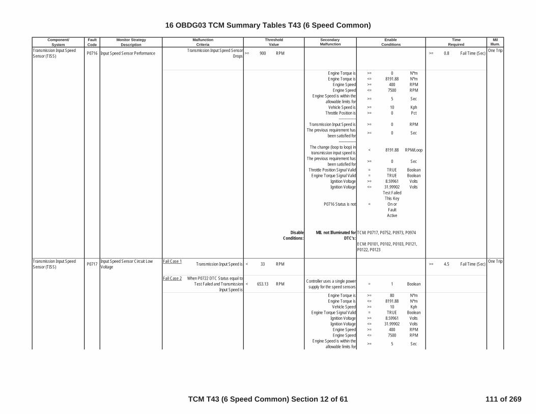
Component/ Fault Monitor Strategy Secondary MilSystem Code Description Malfunction Illum.Criteria Value Conditions Required
Malfunction Threshold Enable Time
Transmission Input SpeedSensor (TISS) P0716 Input Speed Sensor Performance Transmission Input Speed Sensor
Drops >= 900 RPM >= 0.8 Fail Time (Sec) One Trip
Engine Torque is >= 0 N*mEngine Torque is <= 8191.88 N*m
Engine Speed >= 400 RPMEngine Speed <= 7500 RPM
Engine Speed is within theallowable limits for >= 5 Sec
Vehicle Speed is >= 10 KphThrottle Position is >= 0 Pct
--------------Transmission Input Speed is >= 0 RPM
The previous requirement hasbeen satisfied for >= 0 Sec
--------------The change (loop to loop) intransmission input speed is < 8191.88 RPM/Loop
The previous requirement hasbeen satisfied for >= 0 Sec
Throttle Position Signal Valid = TRUE BooleanEngine Torque Signal Valid = TRUE Boolean
Ignition Voltage >= 8.59961 VoltsIgnition Voltage <= 31.99902 Volts
P0716 Status is not =
Test FailedThis Key
On orFaultActive
DisableConditions:
MIL not Illuminated forDTC's:
Transmission Input SpeedSensor (TISS) P0717 Input Speed Sensor Circuit Low
VoltageFail Case 1 Transmission Input Speed is < 33 RPM >= 4.5 Fail Time (Sec) One Trip
Fail Case 2 When P0722 DTC Status equal toTest Failed and Transmission
Input Speed is< 653.13 RPM Controller uses a single power
supply for the speed sensors = 1 Boolean
Engine Torque is >= 80 N*mEngine Torque is <= 8191.88 N*m
Vehicle Speed >= 10 KphEngine Torque Signal Valid = TRUE Boolean
Ignition Voltage >= 8.59961 VoltsIgnition Voltage <= 31.99902 Volts
Engine Speed >= 400 RPMEngine Speed <= 7500 RPM
Engine Speed is within theallowable limits for >= 5 Sec
TCM: P0717, P0752, P0973, P0974
ECM: P0101, P0102, P0103, P0121,P0122, P0123
16 OBDG03 TCM Summary Tables T43 (6 Speed Common)
TCM T43 (6 Speed Common) Section 12 of 61 111 of 269
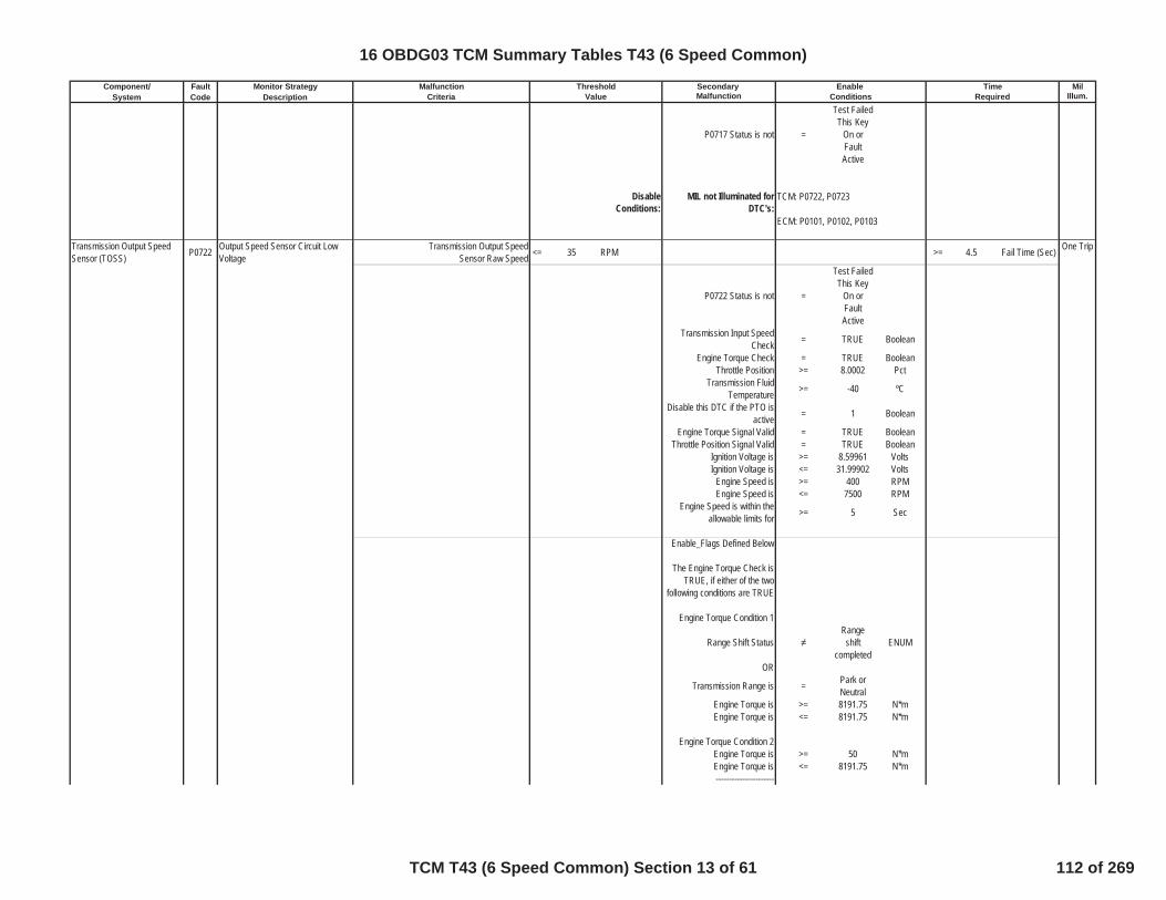
Component/ Fault Monitor Strategy Secondary MilSystem Code Description Malfunction Illum.Criteria Value Conditions Required
Malfunction Threshold Enable Time
P0717 Status is not =
Test FailedThis Key
On orFaultActive
DisableConditions:
MIL not Illuminated forDTC's:
Transmission Output SpeedSensor (TOSS) P0722 Output Speed Sensor Circuit Low
VoltageTransmission Output Speed
Sensor Raw Speed <= 35 RPM >= 4.5 Fail Time (Sec) One Trip
P0722 Status is not =
Test FailedThis Key
On orFaultActive
Transmission Input SpeedCheck = TRUE Boolean
Engine Torque Check = TRUE BooleanThrottle Position >= 8.0002 Pct
Transmission FluidTemperature >= -40 ºC
Disable this DTC if the PTO isactive = 1 Boolean
Engine Torque Signal Valid = TRUE BooleanThrottle Position Signal Valid = TRUE Boolean
Ignition Voltage is >= 8.59961 VoltsIgnition Voltage is <= 31.99902 Volts
Engine Speed is >= 400 RPMEngine Speed is <= 7500 RPM
Engine Speed is within theallowable limits for >= 5 Sec
Enable_Flags Defined Below
The Engine Torque Check isTRUE, if either of the two
following conditions are TRUE
Engine Torque Condition 1
Range Shift StatusRangeshift
completedENUM
OR
Transmission Range is = Park orNeutral
Engine Torque is >= 8191.75 N*mEngine Torque is <= 8191.75 N*m
Engine Torque Condition 2Engine Torque is >= 50 N*mEngine Torque is <= 8191.75 N*m----------------------
TCM: P0722, P0723
ECM: P0101, P0102, P0103
16 OBDG03 TCM Summary Tables T43 (6 Speed Common)
TCM T43 (6 Speed Common) Section 13 of 61 112 of 269

Component/ Fault Monitor Strategy Secondary MilSystem Code Description Malfunction Illum.Criteria Value Conditions Required
Malfunction Threshold Enable Time
The Transmission Input Speed(TIS) Check is TRUE, if eitherof the two following conditions
are TRUE
TIS Check Condition 1Transmission Input Speed is >= 653.13 RPMTransmission Input Speed is <= 5350 RPM
TIS Check Condition 2Engine Speed without the
brake applied is >= 3200 RPM
Engine Speed with the brakeapplied is >= 3200 RPM
Engine Speed is <= 8191.88 RPMController uses a single power
supply for the speed sensors = 1 Boolean
Powertrain Brake Pedal isValid = TRUE Boolean
DisableConditions:
MIL not Illuminated forDTC's:
Transmission Output SpeedSensor (TOSS) P0723 Output Speed Sensor Circuit
IntermittentTransmission Output Speed
Sensor Raw Speed >= 105 RPM >= 0 Enable Time(Sec)
One Trip
Output Speed Delta <= 8192 RPM >= 0 Enable Time(Sec)
Output Speed Drop > 650 RPM >= 1.5Output SpeedDrop RecoveryFail Time (Sec)
AND
Transmission Range is = Driven range(R,D)
----------------------Range_Disable = FALSE See Below
OR----------------------
Neutral_Range_Enable = TRUE See BelowAnd
Neutral_Speed_Enable = TRUE See Beloware TRUE concurrently
----------------------Transmission_Range_Enable = TRUE See Below
Transmission_Input_Speed_Enable = TRUE See Below
No Change in Transfer CaseRange (High <-> Low) for >= 5 Seconds
P0723 Status is not =
Test FailedThis Key
On orFaultActive
TCM: P0716, P0717, P0723
ECM: P0101, P0102, P0103, P0121,P0122, P0123
16 OBDG03 TCM Summary Tables T43 (6 Speed Common)
TCM T43 (6 Speed Common) Section 14 of 61 113 of 269

Component/ Fault Monitor Strategy Secondary MilSystem Code Description Malfunction Illum.Criteria Value Conditions Required
Malfunction Threshold Enable Time
Disable this DTC if the PTO isactive = 1 Boolean
Ignition Voltage is >= 8.59961 VoltsIgnition Voltage is <= 31.99902 Volts
Engine Speed is >= 400 RPMEngine Speed is <= 7500 RPM
Engine Speed is within theallowable limits for >= 5 Sec
Enable_Flags Defined Below
Transmission_Input_Speed_Enable is TRUE when either TISCondition 1 or TIS Condition 2
is TRUE:
TIS Condition 1 is TRUE whenboth of the following conditions
are satsified for>= 0 Enable Time
(Sec)
Input Speed Delta <= 4095.88 RPMRaw Input Speed >= 500 RPM
TIS Condition 2 is TRUE whenALL of the next two conditions
are satisfiedInput Speed = 0 RPM
A Single Power Supply is usedfor all speed sensors = TRUE Boolean
----------------------Neutral_Range_Enable is
TRUE when any of the next 3conditions are TRUE
Transmission Range is = Neutral ENUM
Transmission Range is =Reverse/N
eutralTransitonal
ENUM
Transmission Range is =
Neutral/Drive
Transitional
ENUM
And when a drop occurs
Loop to Loop Drop ofTransmission Output Speed is > 650 RPM
----------------------Range_Disable is TRUE when
any of the next threeconditions are TRUE
Transmission Range is = Park ENUM
Transmission Range is =Park/Reve
rseTransitonal
ENUM
Input Clutch is not = ON (FullyApplied) ENUM
----------------------
16 OBDG03 TCM Summary Tables T43 (6 Speed Common)
TCM T43 (6 Speed Common) Section 15 of 61 114 of 269

Component/ Fault Monitor Strategy Secondary MilSystem Code Description Malfunction Illum.Criteria Value Conditions Required
Malfunction Threshold Enable Time
Neutral_Speed_Enable isTRUE when All of the next
three conditions are satsifiedfor
> 1.5 Seconds
Transmission Output Speed > 130 RPM
The loop to loop change of theTransmission Output Speed is < 20 RPM
The loop to loop change of theTransmission Output Speed is > -10 RPM
----------------------Transmission_Range_Enableis TRUE when one of the next
six conditions is TRUETransmission Range is = Neutral ENUM
Transmission Range is =
Reverse/Neutral
Transitional
ENUM
Transmission Range is =
Neutral/Drive
Transitional
ENUM
Time since a driven range(R,D) has been selected >=
TableBasedTime
PleaseRefer to
Table 21 insupportingdocuments
Sec
Transmission Output SpeedSensor Raw Speed >= 500 RPM
Output Speed when a faultwas detected >= 500 RPM
DisableConditions:
MIL not Illuminated forDTC's:
Torque Converter Clutch(TCC) P0741 TCC System Stuck OFF TCC Pressure >= 750 Kpa >= 2 Enable Time
(Sec)TwoTrips
Either Condition (A) or (B) Must beMet
(A) TCC Slip Error @ TCC OnMode >=
Refer to Table1 in
SupportingDocuments
RPM >= 5 Fail Time (Sec)
(B) TCC Slip @ Lock On Mode >= 130 RPM >= 5 Fail Time (Sec)
TCM: P0973, P0974, P0976, P0977
ECM: P0101, P0102, P0103, P0121,P0122, P0123
16 OBDG03 TCM Summary Tables T43 (6 Speed Common)
TCM T43 (6 Speed Common) Section 16 of 61 115 of 269

Component/ Fault Monitor Strategy Secondary MilSystem Code Description Malfunction Illum.Criteria Value Conditions Required
Malfunction Threshold Enable Time
If Above Conditions Have beenMet, and Fail Timer Expired,
Increment Fail Counter>= 2 TCC Stuck Off
Fail Counter
TCC Mode = On or Lock
Ignition Voltage Lo >= 8.59961 VoltsIgnition Voltage Hi <= 31.99902 Volts
Engine Speed >= 400 RPMEngine Speed <= 7500 RPM
Engine Speed is within theallowable limits for >= 5 Sec
Engine Torque Lo >= 50 N*mEngine Torque Hi <= 8191.88 N*m
Throttle Position Lo >= 8.0002 PctThrottle Position Hi <= 99.9985 Pct2nd Gear Ratio Lo >= 2.19482 Ratio
2nd Gear Ratio High <= 2.52515 Ratio3rd Gear Ratio Lo >= 1.42285 Ratio
3rd Gear Ratio High <= 1.63708 Ratio4th Gear Ratio Lo >= 1.06946 Ratio
4th Gear Ratio High <= 1.23047 Ratio5th Gear Ratio Lo >= 0.79053 Ratio5th Gear Ratio Hi <= 0.90955 Ratio6th Gear Ratio Lo >= 0.62305 Ratio
6th Gear Ratio High <= 0.71692 RatioTransmission Fluid
Temperature Lo >= -6.6563 ºC
Transmission FluidTemperature Hi <= 130 ºC
PTO Not Active = TRUE BooleanEngine Torque Signal Valid = TRUE Boolean
Throttle Position Signal Valid = TRUE BooleanDynamic Mode = FALSE Boolean
P0741 Status is
Test FailedThis Key
On orFaultActive
DisableConditions:
MIL not Illuminated forDTC's:
Torque Converter Clutch(TCC) P0742 TCC System Stuck ON TCC Slip Speed >= -50 RPM One Trip
TCC Slip Speed <= 13 RPM>= 1.5 Fail Time (Sec)
If Above Conditions Have beenMet, and Fail Timer Expired,
Increment Fail Counter>= 6 Fail Counter
TCM: P0716, P0717, P0722, P0723,P0742, P2763, P2764
ECM: P0101, P0102, P0103, P0106,P0107, P0108, P0171, P0172, P0174,P0175, P0201, P0202, P0203, P0204,P0205, P0206, P0207, P0208, P0300,P0301, P0302, P0303, P0304, P0305,P0306, P0307, P0308, P0401, P042E
16 OBDG03 TCM Summary Tables T43 (6 Speed Common)
TCM T43 (6 Speed Common) Section 17 of 61 116 of 269

Component/ Fault Monitor Strategy Secondary MilSystem Code Description Malfunction Illum.Criteria Value Conditions Required
Malfunction Threshold Enable Time
TCC Mode = OffEnable test if Cmnd Gear =
1stFW and value true = 1 Boolean
Enable test if Cmnd Gear =2nd and value true = 0 Boolean
Engine Speed Hi <= 6000 RPMEngine Speed Lo >= 500 RPMVehicle Speed HI <= 511 KPHVehicle Speed Lo >= 1 KPHEngine Torque Hi <= 8191.88 NmEngine Torque Lo >= 80 Nm
Current Range Neutral RangeCurrent Range Reverse Range
Transmission SumpTemperature <= 130 ºC
Transmission SumpTemperature >= 18 ºC
Throttle Position Hyst High >= 5.0003 PctAND
Max Vehicle Speed to MeetThrottle Enable <= 8 KPH
Once Hyst High has been met,the enable will remain while
Throttle Position>= 2.0004 Pct
Disable for Throttle Position >= 75 PctDisable if PTO active and
value true = 1 Boolean
Disable if in D1 and value true = 1 BooleanDisable if in D2 and value true = 1 BooleanDisable if in D3 and value true = 1 BooleanDisable if in D4 and value true = 1 BooleanDisable if in D5 and value true = 1 BooleanDisable if in MUMD and value
true = 1 Boolean
Disable if in TUTD and valuetrue = 1 Boolean
4 Wheel Drive Low Active = FALSE BooleanDisable if Air Purge active and
value false = 0 Boolean
RVT Diagnostic Active = FALSE BooleanIgnition Voltage >= 8.59961 VIgnition Voltage <= 31.99902 VVehicle Speed <= 511 KPHEngine Speed >= 400 RPMEngine Speed <= 7500 RPM
Engine Speed is within theallowable limits for >= 5 Sec
Engine Torque Signal Valid = TRUE BooleanThrottle Position Signal Valid = TRUE Boolean
P0742 Status is
Test FailedThis Key
On orFaultActive
16 OBDG03 TCM Summary Tables T43 (6 Speed Common)
TCM T43 (6 Speed Common) Section 18 of 61 117 of 269
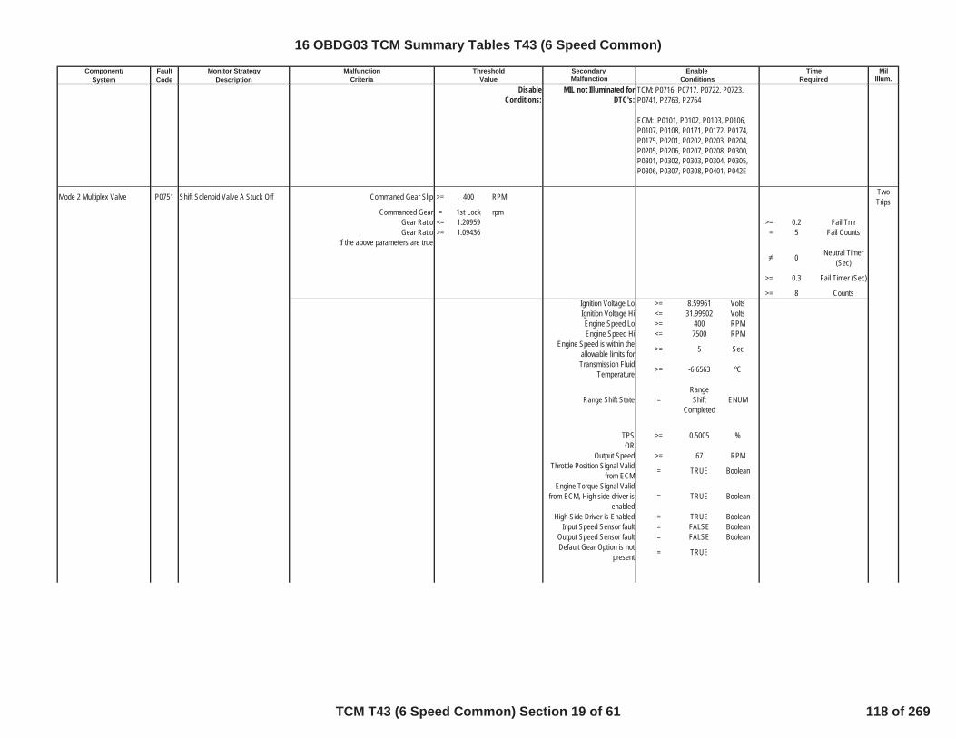
Component/ Fault Monitor Strategy Secondary MilSystem Code Description Malfunction Illum.Criteria Value Conditions Required
Malfunction Threshold Enable Time
DisableConditions:
MIL not Illuminated forDTC's:
Mode 2 Multiplex Valve P0751 Shift Solenoid Valve A Stuck Off Commaned Gear Slip >= 400 RPM TwoTrips
Commanded Gear = 1st Lock rpmGear Ratio <= 1.20959 >= 0.2 Fail TmrGear Ratio >= 1.09436 = 5 Fail Counts
If the above parameters are true
0 Neutral Timer(Sec)
>= 0.3 Fail Timer (Sec)
>= 8 CountsIgnition Voltage Lo >= 8.59961 VoltsIgnition Voltage Hi <= 31.99902 VoltsEngine Speed Lo >= 400 RPMEngine Speed Hi <= 7500 RPM
Engine Speed is within theallowable limits for >= 5 Sec
Transmission FluidTemperature >= -6.6563 ºC
Range Shift State =RangeShift
CompletedENUM
TPS >= 0.5005 %OR
Output Speed >= 67 RPMThrottle Position Signal Valid
from ECM = TRUE Boolean
Engine Torque Signal Validfrom ECM, High side driver is
enabled= TRUE Boolean
High-Side Driver is Enabled = TRUE BooleanInput Speed Sensor fault = FALSE Boolean
Output Speed Sensor fault = FALSE BooleanDefault Gear Option is not
present = TRUE
TCM: P0716, P0717, P0722, P0723,P0741, P2763, P2764
ECM: P0101, P0102, P0103, P0106,P0107, P0108, P0171, P0172, P0174,P0175, P0201, P0202, P0203, P0204,P0205, P0206, P0207, P0208, P0300,P0301, P0302, P0303, P0304, P0305,P0306, P0307, P0308, P0401, P042E
16 OBDG03 TCM Summary Tables T43 (6 Speed Common)
TCM T43 (6 Speed Common) Section 19 of 61 118 of 269

Component/ Fault Monitor Strategy Secondary MilSystem Code Description Malfunction Illum.Criteria Value Conditions Required
Malfunction Threshold Enable Time
DisableConditions:
MIL not Illuminated forDTC's:
Mode 2 Multiplex Valve P0752 Shift Solenoid Valve A Stuck On Gear Box Slip >= 400 RPM One Trip
Commanded Gear = 3rd GearCommanded Gear has Achieved
1st Locked OR 1st Free-WheelOR 2nd with Mode 2 Sol.
Commanded On
= TRUE Boolean
If the above parameters are true
>=
Please Referto Table 16 in
SupportingDocuments
Neutral Timer(Sec)
Command 4th Gear once OutputShaft Speed <= 400 RPM
If Gear Ratio >= 3.82568And Gear Ratio <= 4.22839
>= 1.5 Fail Timer (Sec)
>= 5 CountsIgnition Voltage Lo >= 8.59961 VoltsIgnition Voltage Hi <= 31.99902 VoltsEngine Speed Lo >= 400 RPMEngine Speed Hi <= 7500 RPM
Engine Speed is within theallowable limits for >= 5 Sec
High-Side Driver is Enabled = TRUE BooleanThrottle Position Signal Valid
from ECM = TRUE Boolean
Output Speed >= 67 RPMOR
TPS >= 0.5005 %
Range Shift State =RangeShift
CompletedENUM
Transmission FluidTemperature >= -6.6563 ºC
Input Speed Sensor fault = FALSE BooleanOutput Speed Sensor fault = FALSE BooleanDefault Gear Option is not
present = TRUE
TCM: P0716, P0717, P0722, P0723,P182E
ECM: P0101, P0102, P0103, P0106,P0107, P0108, P0171, P0172, P0174,P0175, P0201, P0202, P0203, P0204,P0205, P0206, P0207, P0208, P0300,P0301, P0302, P0303, P0304, P0305,P0306, P0307, P0308, P0401, P042E
16 OBDG03 TCM Summary Tables T43 (6 Speed Common)
TCM T43 (6 Speed Common) Section 20 of 61 119 of 269
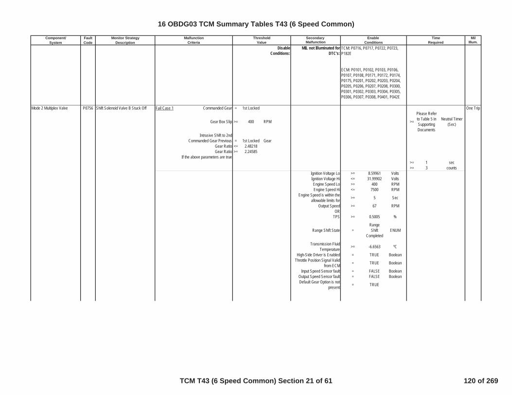
Component/ Fault Monitor Strategy Secondary MilSystem Code Description Malfunction Illum.Criteria Value Conditions Required
Malfunction Threshold Enable Time
DisableConditions:
MIL not Illuminated forDTC's:
Mode 2 Multiplex Valve P0756 Shift Solenoid Valve B Stuck Off Fail Case 1 Commanded Gear = 1st Locked One Trip
Gear Box Slip >= 400 RPM >=
Please Referto Table 5 inSupportingDocuments
Neutral Timer(Sec)
Intrusive Shift to 2ndCommanded Gear Previous = 1st Locked Gear
Gear Ratio <= 2.48218Gear Ratio >= 2.24585
If the above parameters are true>= 1 sec>= 3 counts
Ignition Voltage Lo >= 8.59961 VoltsIgnition Voltage Hi <= 31.99902 VoltsEngine Speed Lo >= 400 RPMEngine Speed Hi <= 7500 RPM
Engine Speed is within theallowable limits for >= 5 Sec
Output Speed >= 67 RPMOR
TPS >= 0.5005 %
Range Shift State =RangeShift
CompletedENUM
Transmission FluidTemperature >= -6.6563 ºC
High-Side Driver is Enabled = TRUE BooleanThrottle Position Signal Valid
from ECM = TRUE Boolean
Input Speed Sensor fault = FALSE BooleanOutput Speed Sensor fault = FALSE BooleanDefault Gear Option is not
present = TRUE
TCM: P0716, P0717, P0722, P0723,P182E
ECM: P0101, P0102, P0103, P0106,P0107, P0108, P0171, P0172, P0174,P0175, P0201, P0202, P0203, P0204,P0205, P0206, P0207, P0208, P0300,P0301, P0302, P0303, P0304, P0305,P0306, P0307, P0308, P0401, P042E
16 OBDG03 TCM Summary Tables T43 (6 Speed Common)
TCM T43 (6 Speed Common) Section 21 of 61 120 of 269
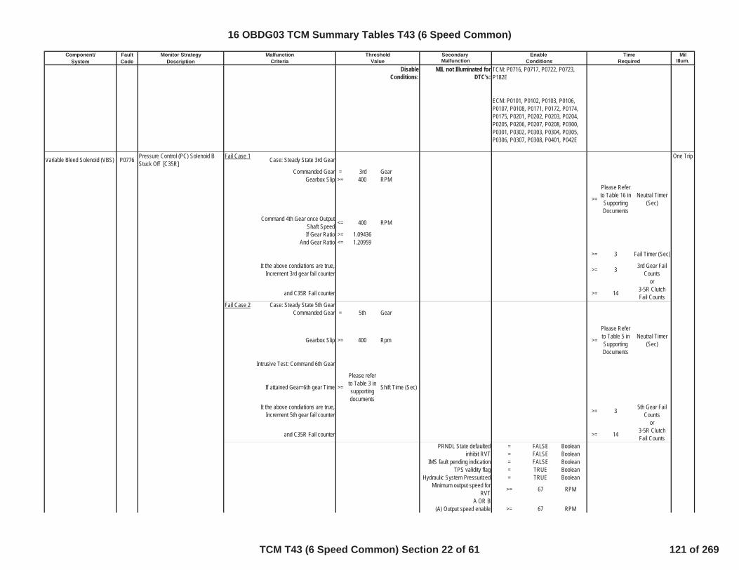
Component/ Fault Monitor Strategy Secondary MilSystem Code Description Malfunction Illum.Criteria Value Conditions Required
Malfunction Threshold Enable Time
DisableConditions:
MIL not Illuminated forDTC's:
Variable Bleed Solenoid (VBS) P0776 Pressure Control (PC) Solenoid BStuck Off [C35R]
Fail Case 1 Case: Steady State 3rd Gear One Trip
Commanded Gear = 3rd GearGearbox Slip >= 400 RPM
>=
Please Referto Table 16 in
SupportingDocuments
Neutral Timer(Sec)
Command 4th Gear once OutputShaft Speed <= 400 RPM
If Gear Ratio >= 1.09436And Gear Ratio <= 1.20959
>= 3 Fail Timer (Sec)
It the above condiations are true,Increment 3rd gear fail counter >= 3 3rd Gear Fail
Countsor
and C35R Fail counter >= 14 3-5R ClutchFail Counts
Fail Case 2 Case: Steady State 5th GearCommanded Gear = 5th Gear
Gearbox Slip >= 400 Rpm >=
Please Referto Table 5 inSupportingDocuments
Neutral Timer(Sec)
Intrusive Test: Command 6th Gear
If attained Gear=6th gear Time >=
Please referto Table 3 insupportingdocuments
Shift Time (Sec)
It the above condiations are true,Increment 5th gear fail counter >= 3 5th Gear Fail
Countsor
and C35R Fail counter >= 14 3-5R ClutchFail Counts
PRNDL State defaulted = FALSE Booleaninhibit RVT = FALSE Boolean
IMS fault pending indication = FALSE BooleanTPS validity flag = TRUE Boolean
Hydraulic System Pressurized = TRUE BooleanMinimum output speed for
RVT >= 67 RPM
A OR B(A) Output speed enable >= 67 RPM
TCM: P0716, P0717, P0722, P0723,P182E
ECM: P0101, P0102, P0103, P0106,P0107, P0108, P0171, P0172, P0174,P0175, P0201, P0202, P0203, P0204,P0205, P0206, P0207, P0208, P0300,P0301, P0302, P0303, P0304, P0305,P0306, P0307, P0308, P0401, P042E
16 OBDG03 TCM Summary Tables T43 (6 Speed Common)
TCM T43 (6 Speed Common) Section 22 of 61 121 of 269
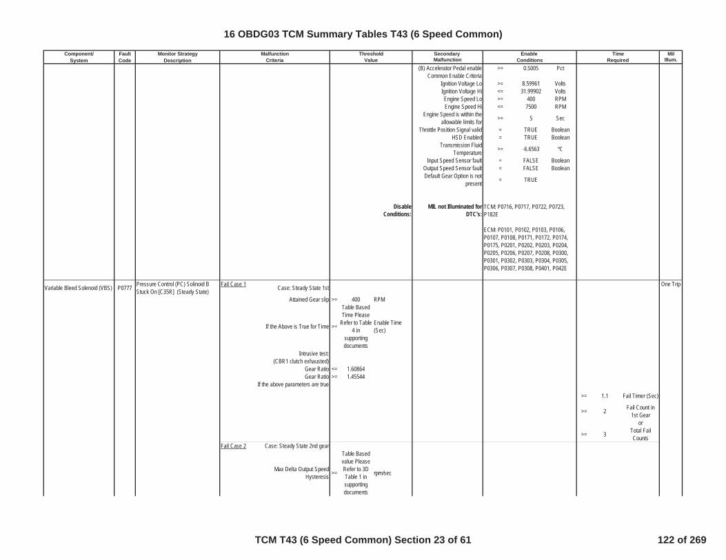
Component/ Fault Monitor Strategy Secondary MilSystem Code Description Malfunction Illum.Criteria Value Conditions Required
Malfunction Threshold Enable Time
(B) Accelerator Pedal enable >= 0.5005 PctCommon Enable Criteria
Ignition Voltage Lo >= 8.59961 VoltsIgnition Voltage Hi <= 31.99902 VoltsEngine Speed Lo >= 400 RPMEngine Speed Hi <= 7500 RPM
Engine Speed is within theallowable limits for >= 5 Sec
Throttle Position Signal valid = TRUE BooleanHSD Enabled = TRUE Boolean
Transmission FluidTemperature >= -6.6563 ºC
Input Speed Sensor fault = FALSE BooleanOutput Speed Sensor fault = FALSE BooleanDefault Gear Option is not
present = TRUE
DisableConditions:
MIL not Illuminated forDTC's:
Variable Bleed Solenoid (VBS) P0777 Pressure Control (PC) Solinoid BStuck On [C35R] (Steady State)
Fail Case 1 Case: Steady State 1st One Trip
Attained Gear slip >= 400 RPM
If the Above is True for Time >=
Table BasedTime Please
Refer to Table4 in
supportingdocuments
Enable Time(Sec)
Intrusive test:(CBR1 clutch exhausted)
Gear Ratio <= 1.60864Gear Ratio >= 1.45544
If the above parameters are true
>= 1.1 Fail Timer (Sec)
>= 2 Fail Count in1st Gear
or
>= 3 Total FailCounts
Fail Case 2 Case: Steady State 2nd gear
Max Delta Output SpeedHysteresis >=
Table Basedvalue PleaseRefer to 3DTable 1 insupportingdocuments
rpm/sec
TCM: P0716, P0717, P0722, P0723,P182E
ECM: P0101, P0102, P0103, P0106,P0107, P0108, P0171, P0172, P0174,P0175, P0201, P0202, P0203, P0204,P0205, P0206, P0207, P0208, P0300,P0301, P0302, P0303, P0304, P0305,P0306, P0307, P0308, P0401, P042E
16 OBDG03 TCM Summary Tables T43 (6 Speed Common)
TCM T43 (6 Speed Common) Section 23 of 61 122 of 269

Component/ Fault Monitor Strategy Secondary MilSystem Code Description Malfunction Illum.Criteria Value Conditions Required
Malfunction Threshold Enable Time
Min Delta Output SpeedHysteresis >=
Table Basedvalue PleaseRefer to 3DTable 2 insupportingdocuments
rpm/sec
If the Above is True for Time >=
Table BasedTime Please
Refer to Table17 in
supportingdocuments
Sec
Intrusive test: (CB26 clutch exhausted)
Gear Ratio <= 1.60864Gear Ratio >= 1.45544
If the above parameters are true
>= 1.1 Fail Timer (Sec)
>= 3 Fail Count in2nd Gear
or
>= 3 Total FailCounts
Fail Case 3 Case: Steady State 4th gear
Max Delta Output SpeedHysteresis >=
Table Basedvalue PleaseRefer to 3DTable 1 insupportingdocuments
rpm/sec
Min Delta Output SpeedHysteresis >=
Table Basedvalue PleaseRefer to 3DTable 2 insupportingdocuments
rpm/sec
If the Above is True for Time >=
Table BasedTime Please
Refer to Table17 in
supportingdocuments
Sec
Intrusive test: (C1234 clutch exhausted)
Gear Ratio <= 0.89465Gear Ratio >= 0.80945
If the above parameters are true
>= 1.1 Fail Timer (Sec)
>= 3 Fail Count in4th Gear
or
>= 3 Total FailCounts
Fail Case 4 Case: Steady State 6th gear
16 OBDG03 TCM Summary Tables T43 (6 Speed Common)
TCM T43 (6 Speed Common) Section 24 of 61 123 of 269
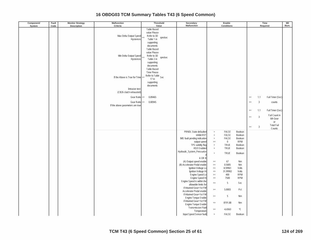
Component/ Fault Monitor Strategy Secondary MilSystem Code Description Malfunction Illum.Criteria Value Conditions Required
Malfunction Threshold Enable Time
Max Delta Output SpeedHysteresis >=
Table Basedvalue PleaseRefer to 3DTable 1 insupportingdocuments
rpm/sec
Min Delta Output SpeedHysteresis >=
Table Basedvalue PleaseRefer to 3DTable 2 insupportingdocuments
rpm/sec
If the Above is True for Time >=
Table BasedTime Please
Refer to Table17 in
supportingdocuments
Sec
Intrusive test: (CB26 clutch exhausted)
Gear Ratio <= 0.89465 >= 1.1 Fail Timer (Sec)
Gear Ratio >= 0.80945 >= 3 countsIf the above parameters are true
>= 1.1 Fail Timer (Sec)
>= 3 Fail Count in6th Gear
or
>= 3 Total FailCounts
PRNDL State defaulted = FALSE Booleaninhibit RVT = FALSE Boolean
IMS fault pending indication = FALSE Booleanoutput speed >= 0 RPM
TPS validity flag = TRUE BooleanHSD Enabled = TRUE Boolean
Hydraulic_System_Pressurized = TRUE Boolean
A OR B(A) Output speed enable >= 67 Nm
(B) Accelerator Pedal enable >= 0.5005 NmIgnition Voltage Lo >= 8.59961 VoltsIgnition Voltage Hi <= 31.99902 VoltsEngine Speed Lo >= 400 RPMEngine Speed Hi <= 7500 RPM
Engine Speed is within theallowable limits for >= 5 Sec
if Attained Gear=1st FWAccelerator Pedal enable >= 5.0003 Pct
if Attained Gear=1st FWEngine Torque Enable >= 5 Nm
if Attained Gear=1st FWEngine Torque Enable <= 8191.88 Nm
Transmission FluidTemperature >= -6.6563 ºC
Input Speed Sensor fault = FALSE Boolean
16 OBDG03 TCM Summary Tables T43 (6 Speed Common)
TCM T43 (6 Speed Common) Section 25 of 61 124 of 269
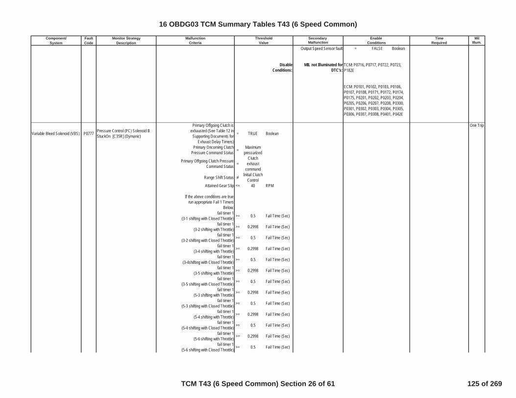
Component/ Fault Monitor Strategy Secondary MilSystem Code Description Malfunction Illum.Criteria Value Conditions Required
Malfunction Threshold Enable Time
Output Speed Sensor fault = FALSE Boolean
DisableConditions:
MIL not Illuminated forDTC's:
Variable Bleed Solenoid (VBS) P0777 Pressure Control (PC) Solenoid BStuckOn [C35R] (Dymanic)
Primary Offgoing Clutch isexhausted (See Table 12 in
Supporting Documents forExhaust Delay Timers)
= TRUE Boolean
One Trip
Primary Oncoming ClutchPressure Command Status = Maximum
pressurized
Primary Offgoing Clutch PressureCommand Status =
Clutchexhaust
command
Range Shift Status Initial ClutchControl
Attained Gear Slip <= 40 RPM
If the above conditions are truerun appropriate Fail 1 Timers
Below:fail timer 1
(3-1 shifting with Closed Throttle) >= 0.5 Fail Time (Sec)
fail timer 1(3-2 shifting with Throttle) >= 0.2998 Fail Time (Sec)
fail timer 1(3-2 shifting with Closed Throttle) >= 0.5 Fail Time (Sec)
fail timer 1(3-4 shifting with Throttle) >= 0.2998 Fail Time (Sec)
fail timer 1(3-4shifting with Closed Throttle) >= 0.5 Fail Time (Sec)
fail timer 1(3-5 shifting with Throttle) >= 0.2998 Fail Time (Sec)
fail timer 1(3-5 shifting with Closed Throttle) >= 0.5 Fail Time (Sec)
fail timer 1(5-3 shifting with Throttle) >= 0.2998 Fail Time (Sec)
fail timer 1(5-3 shifting with Closed Throttle) >= 0.5 Fail Time (Sec)
fail timer 1(5-4 shifting with Throttle) >= 0.2998 Fail Time (Sec)
fail timer 1(5-4 shifting with Closed Throttle) >= 0.5 Fail Time (Sec)
fail timer 1(5-6 shifting with Throttle) >= 0.2998 Fail Time (Sec)
fail timer 1(5-6 shifting with Closed Throttle) >= 0.5 Fail Time (Sec)
TCM: P0716, P0717, P0722, P0723,P182E
ECM: P0101, P0102, P0103, P0106,P0107, P0108, P0171, P0172, P0174,P0175, P0201, P0202, P0203, P0204,P0205, P0206, P0207, P0208, P0300,P0301, P0302, P0303, P0304, P0305,P0306, P0307, P0308, P0401, P042E
16 OBDG03 TCM Summary Tables T43 (6 Speed Common)
TCM T43 (6 Speed Common) Section 26 of 61 125 of 269

Component/ Fault Monitor Strategy Secondary MilSystem Code Description Malfunction Illum.Criteria Value Conditions Required
Malfunction Threshold Enable Time
If Attained Gear Slip is Less thanAbove Cal Increment Fail Timers >=
Total FailTime = (Fail 1+ Fail 2) See
EnableTimers for FailTimer 1, andReferenceSupportingTable 15 forFail Timer 2
sec
If fail timer is greater thanthreshold increment corresponding
gear fail counter and total failcounter
3rd gear fail counter >= 3 3rd gear failcounts
OR
5th gear fail counter >= 3 5th gear failcounts
ORTotal fail counter >= 5 total fail counts
TUT Enable temperature >= -6.6563 ºCInput Speed Sensor fault = FALSE Boolean
Output Speed Sensor fault = FALSE BooleanCommand / Attained Gear 1st Boolean
High Side Driver ON = TRUE Booleanoutput speed limit for TUT >= 100 RPM
input speed limit for TUT >= 150 RPMPRNDL state defaulted = FALSE Boolean
IMS Fault Pending = FALSE BooleanService Fast Learn Mode = FALSE Boolean
HSD Enabled = TRUE BooleanDefault Gear Option is not
present = TRUE
DisableConditions:
MIL not Illuminated forDTC's:
Variable Bleed Solenoid (VBS) P0796 Pressure Control (PC) Solenoid CStuck Off [C456] (Steady State)
Fail Case 1 Case: Steady State 4th Gear One Trip
Gear slip >= 400 RPM >=
Please SeeTable 5 For
Neutral TimeCal
Neutral Timer(Sec)
Intrusive test:commanded 5th gear
TCM: P0716, P0717, P0722, P0723,P182E
ECM: P0101, P0102, P0103, P0106,P0107, P0108, P0171, P0172, P0174,P0175, P0201, P0202, P0203, P0204,P0205, P0206, P0207, P0208, P0300,P0301, P0302, P0303, P0304, P0305,P0306, P0307, P0308, P0401, P042E
16 OBDG03 TCM Summary Tables T43 (6 Speed Common)
TCM T43 (6 Speed Common) Section 27 of 61 126 of 269
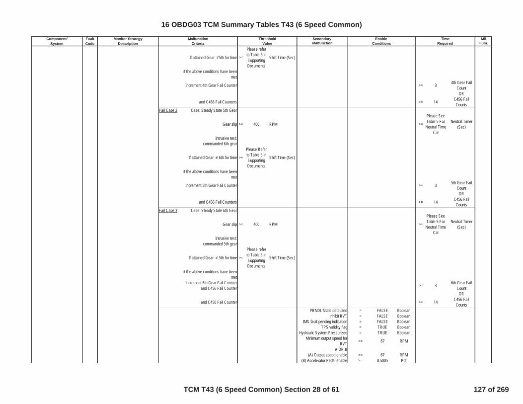
Component/ Fault Monitor Strategy Secondary MilSystem Code Description Malfunction Illum.Criteria Value Conditions Required
Malfunction Threshold Enable Time
If attained Gear 5th for time >=
Please referto Table 3 inSupportingDocuments
Shift Time (Sec)
if the above conditions have beenmet
Increment 4th Gear Fail Counter >= 3 4th Gear FailCount
OR
and C456 Fail Counters >= 14 C456 FailCounts
Fail Case 2 Case: Steady State 5th Gear
Gear slip >= 400 RPM >=
Please SeeTable 5 For
Neutral TimeCal
Neutral Timer(Sec)
Intrusive test:commanded 6th gear
If attained Gear 6th for time >=
Please Referto Table 3 inSupportingDocuments
Shift Time (Sec)
if the above conditions have beenmet
Increment 5th Gear Fail Counter >= 3 5th Gear FailCount
OR
and C456 Fail Counters >= 14 C456 FailCounts
Fail Case 3 Case: Steady State 6th Gear
Gear slip >= 400 RPM >=
Please SeeTable 5 For
Neutral TimeCal
Neutral Timer(Sec)
Intrusive test:commanded 5th gear
If attained Gear 5th for time >=
Please referto Table 3 inSupportingDocuments
Shift Time (Sec)
if the above conditions have beenmet
Increment 6th Gear Fail Counterand C456 Fail Counter >= 3 6th Gear Fail
CountOR
and C456 Fail Counter >= 14 C456 FailCounts
PRNDL State defaulted = FALSE Booleaninhibit RVT = FALSE Boolean
IMS fault pending indication = FALSE BooleanTPS validity flag = TRUE Boolean
Hydraulic System Pressurized = TRUE BooleanMinimum output speed for
RVT >= 67 RPM
A OR B(A) Output speed enable >= 67 RPM
(B) Accelerator Pedal enable >= 0.5005 Pct
16 OBDG03 TCM Summary Tables T43 (6 Speed Common)
TCM T43 (6 Speed Common) Section 28 of 61 127 of 269
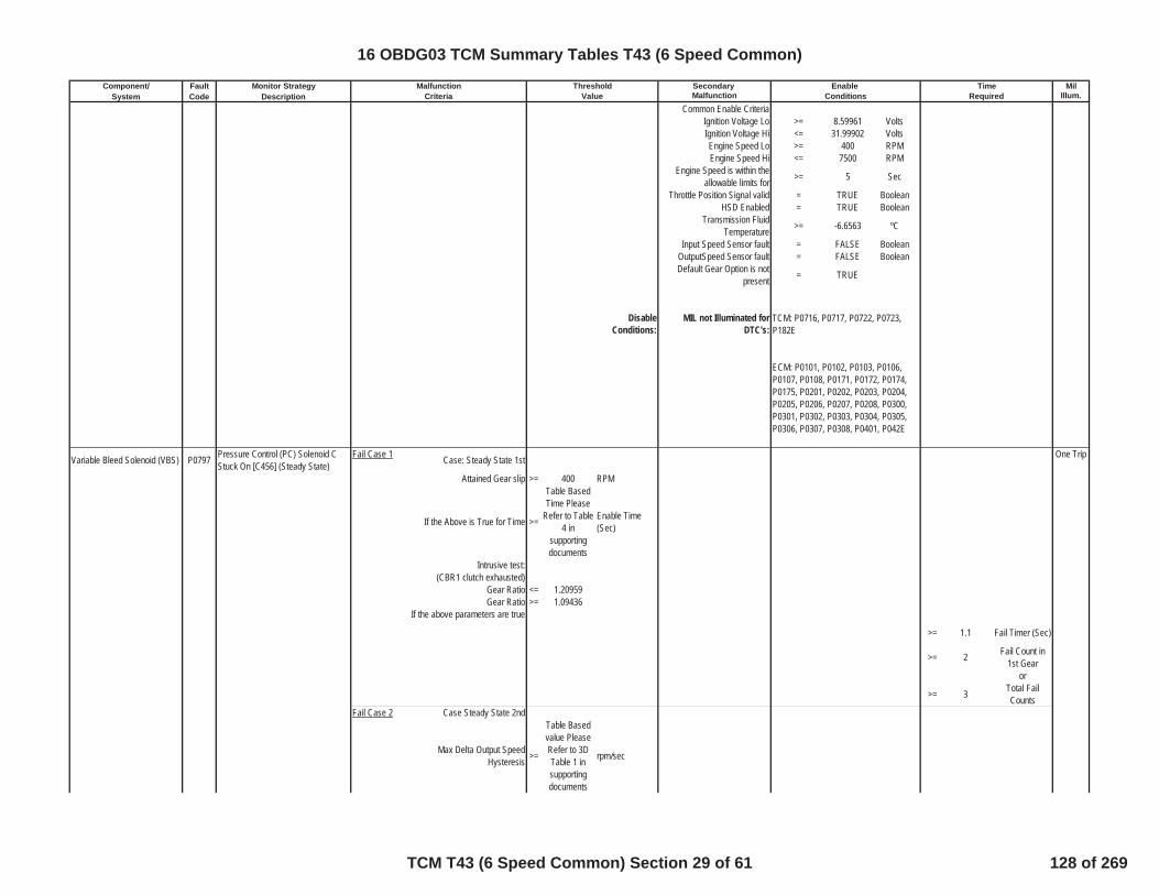
Component/ Fault Monitor Strategy Secondary MilSystem Code Description Malfunction Illum.Criteria Value Conditions Required
Malfunction Threshold Enable Time
Common Enable CriteriaIgnition Voltage Lo >= 8.59961 VoltsIgnition Voltage Hi <= 31.99902 VoltsEngine Speed Lo >= 400 RPMEngine Speed Hi <= 7500 RPM
Engine Speed is within theallowable limits for >= 5 Sec
Throttle Position Signal valid = TRUE BooleanHSD Enabled = TRUE Boolean
Transmission FluidTemperature >= -6.6563 ºC
Input Speed Sensor fault = FALSE BooleanOutputSpeed Sensor fault = FALSE BooleanDefault Gear Option is not
present = TRUE
DisableConditions:
MIL not Illuminated forDTC's:
Variable Bleed Solenoid (VBS) P0797 Pressure Control (PC) Solenoid CStuck On [C456] (Steady State)
Fail Case 1 Case: Steady State 1st One Trip
Attained Gear slip >= 400 RPM
If the Above is True for Time >=
Table BasedTime Please
Refer to Table4 in
supportingdocuments
Enable Time(Sec)
Intrusive test:(CBR1 clutch exhausted)
Gear Ratio <= 1.20959Gear Ratio >= 1.09436
If the above parameters are true
>= 1.1 Fail Timer (Sec)
>= 2 Fail Count in1st Gear
or
>= 3 Total FailCounts
Fail Case 2 Case Steady State 2nd
Max Delta Output SpeedHysteresis >=
Table Basedvalue PleaseRefer to 3DTable 1 insupportingdocuments
rpm/sec
TCM: P0716, P0717, P0722, P0723,P182E
ECM: P0101, P0102, P0103, P0106,P0107, P0108, P0171, P0172, P0174,P0175, P0201, P0202, P0203, P0204,P0205, P0206, P0207, P0208, P0300,P0301, P0302, P0303, P0304, P0305,P0306, P0307, P0308, P0401, P042E
16 OBDG03 TCM Summary Tables T43 (6 Speed Common)
TCM T43 (6 Speed Common) Section 29 of 61 128 of 269

Component/ Fault Monitor Strategy Secondary MilSystem Code Description Malfunction Illum.Criteria Value Conditions Required
Malfunction Threshold Enable Time
Min Delta Output SpeedHysteresis >=
Table Basedvalue PleaseRefer to 3DTable 2 insupportingdocuments
rpm/sec
If the Above is True for Time >=
Table BasedTime Please
Refer to Table17 in
supportingdocuments
Sec
Intrusive test: (CB26 clutch exhausted)
Gear Ratio <= 1.20959Gear Ratio >= 1.09436
If the above parameters are true
>= 1.1 Fail Timer (Sec)
>= 3 Fail Count in2nd Gear
or
>= 3 Total fail counts
Fail Case 3 Case Steady State 3rd
Max Delta Output SpeedHysteresis >=
Table Basedvalue PleaseRefer to 3DTable 1 insupportingdocuments
rpm/sec
Min Delta Output SpeedHysteresis >=
Table Basedvalue PleaseRefer to 3DTable 2 insupportingdocuments
rpm/sec
If the Above is True for Time >=
Table BasedTime Please
Refer to Table17 in
supportingdocuments
Sec
Intrusive test: (C35R clutch exhausted)
Gear Ratio <= 1.20959Gear Ratio >= 1.09436
If the above parameters are true
>= 1.1 Fail Timer (Sec)
>= 3 Fail Count in3rd Gear
OR
>= 3 Total FailCounts
PRNDL State defaulted = FALSE Boolean
16 OBDG03 TCM Summary Tables T43 (6 Speed Common)
TCM T43 (6 Speed Common) Section 30 of 61 129 of 269
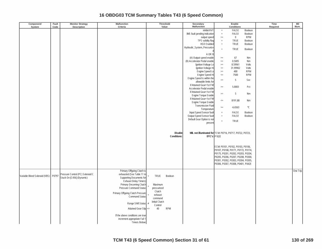
Component/ Fault Monitor Strategy Secondary MilSystem Code Description Malfunction Illum.Criteria Value Conditions Required
Malfunction Threshold Enable Time
inhibit RVT = FALSE BooleanIMS fault pending indication = FALSE Boolean
output speed >= 0 RPMTPS validity flag = TRUE Boolean
HSD Enabled = TRUE BooleanHydraulic_System_Pressurize
d = TRUE Boolean
A OR B(A) Output speed enable >= 67 Nm
(B) Accelerator Pedal enable >= 0.5005 NmIgnition Voltage Lo >= 8.59961 VoltsIgnition Voltage Hi <= 31.99902 VoltsEngine Speed Lo >= 400 RPMEngine Speed Hi <= 7500 RPM
Engine Speed is within theallowable limits for >= 5 Sec
if Attained Gear=1st FWAccelerator Pedal enable >= 5.0003 Pct
if Attained Gear=1st FWEngine Torque Enable >= 5 Nm
if Attained Gear=1st FWEngine Torque Enable <= 8191.88 Nm
Transmission FluidTemperature >= -6.6563 ºC
Input Speed Sensor fault = FALSE BooleanOutput Speed Sensor fault = FALSE BooleanDefault Gear Option is not
present = TRUE
DisableConditions:
MIL not Illuminated forDTC's:
Variable Bleed Solenoid (VBS) P0797 Pressure Control (PC) Solenoid CStuck On [C456] (Dynamic)
Primary Offgoing Clutch isexhausted (See Table 11 in
Supporting Documents forExhaust Delay Timers)
= TRUE Boolean
One Trip
Primary Oncoming ClutchPressure Command Status = Maximum
pressurized
Primary Offgoing Clutch PressureCommand Status =
Clutchexhaust
command
Range Shift Status Initial ClutchControl
Attained Gear Slip <= 40 RPM
If the above conditions are trueincrement appropriate Fail 1
Timers Below:
TCM: P0716, P0717, P0722, P0723,P182E
ECM: P0101, P0102, P0103, P0106,P0107, P0108, P0171, P0172, P0174,P0175, P0201, P0202, P0203, P0204,P0205, P0206, P0207, P0208, P0300,P0301, P0302, P0303, P0304, P0305,P0306, P0307, P0308, P0401, P042E
16 OBDG03 TCM Summary Tables T43 (6 Speed Common)
TCM T43 (6 Speed Common) Section 31 of 61 130 of 269

Component/ Fault Monitor Strategy Secondary MilSystem Code Description Malfunction Illum.Criteria Value Conditions Required
Malfunction Threshold Enable Time
fail timer 1(4-1 shifting with throttle) >= 0.2998 Fail Time (Sec)
fail timer 1(4-1 shifting without throttle) >= 0.5 Fail Time (Sec)
fail timer 1(4-2 shifting with throttle) >= 0.2998 Fail Time (Sec)
fail timer 1(4-2 shifting without throttle) >= 0.5 Fail Time (Sec)
fail timer 1(4-3 shifting with throttle) >= 0.2998 Fail Time (Sec)
fail timer 1(4-3 shifting without throttle) >= 0.5 Fail Time (Sec)
fail timer 1(5-3 shifting with throttle) >= 0.2998 Fail Time (Sec)
fail timer 1(5-3 shifting without throttle) >= 0.5 Fail Time (Sec)
fail timer 1(6-2 shifting with throttle) >= 0.2998 Fail Time (Sec)
fail timer 1(6-2 shifting without throttle) >= 0.5 Fail Time (Sec)
If Attained Gear Slip is Less thanAbove Cal Increment Fail Timers >=
Total FailTime = (Fail 1+ Fail 2) See
EnableTimers for FailTimer 1, andReferenceSupportingTable 15 forFail Timer 2
sec
If fail timer is greater thanthreshold increment corresponding
gear fail counter and total failcounter
4th gear fail counter >= 3 Fail CounterFrom 4th Gear
OR
5th gear fail counter >= 3 Fail CounterFrom 5th Gear
OR
6th gear fail counter >= 3 Fail CounterFrom 6th Gear
OR
Total fail counter >= 5 Total FailCounter
TUT Enable temperature >= -6.6563 ºCInput Speed Sensor fault = FALSE Boolean
Output Speed Sensor fault = FALSE BooleanCommand / Attained Gear 1st Boolean
High Side Driver ON = TRUE Booleanoutput speed limit for TUT >= 100 RPM
input speed limit for TUT >= 150 RPMPRNDL state defaulted = FALSE Boolean
IMS Fault Pending = FALSE BooleanService Fast Learn Mode = FALSE Boolean
HSD Enabled = TRUE Boolean
16 OBDG03 TCM Summary Tables T43 (6 Speed Common)
TCM T43 (6 Speed Common) Section 32 of 61 131 of 269

Component/ Fault Monitor Strategy Secondary MilSystem Code Description Malfunction Illum.Criteria Value Conditions Required
Malfunction Threshold Enable Time
DisableConditions:
MIL not Illuminated forDTC's:
Tap Up Tap Down Switch(TUTD) P0815 Upshift Switch Circuit Fail Case 1 Tap Up Switch Stuck in the Up
Position in Range 1 Enabled = 1 Boolean SpecialNo MIL
Tap Up Switch Stuck in the UpPosition in Range 2 Enabled = 1 Boolean
Tap Up Switch Stuck in the UpPosition in Range 3 Enabled = 1 Boolean
Tap Up Switch Stuck in the UpPosition in Range 4 Enabled = 1 Boolean
Tap Up Switch Stuck in the UpPosition in Range 5 Enabled = 1 Boolean
Tap Up Switch Stuck in the UpPosition in Range 6 Enabled = 1 Boolean
Tap Up Switch Stuck in the UpPosition in Neutral Enabled = 1 Boolean
Tap Up Switch Stuck in the UpPosition in Park Enabled = 1 Boolean
Tap Up Switch Stuck in the UpPosition in Reverse Enabled = 1 Boolean
Tap Up Switch ON = TRUE Boolean >= 1 Fail Time (Sec)
Fail Case 2 Tap Up Switch Stuck in the UpPosition in Range 1 Enabled = 1 Boolean
Tap Up Switch Stuck in the UpPosition in Range 2 Enabled = 1 Boolean
Tap Up Switch Stuck in the UpPosition in Range 3 Enabled = 1 Boolean
Tap Up Switch Stuck in the UpPosition in Range 4 Enabled = 1 Boolean
Tap Up Switch Stuck in the UpPosition in Range 5 Enabled = 1 Boolean
Tap Up Switch Stuck in the UpPosition in Range 6 Enabled = 1 Boolean
Tap Up Switch Stuck in the UpPosition in Neutral Enabled = 1 Boolean
Tap Up Switch Stuck in the UpPosition in Park Enabled = 1 Boolean
Tap Up Switch Stuck in the UpPosition in Reverse Enabled = 1 Boolean
Tap Up Switch ON = TRUE BooleanNOTE: Both Failcase1 and
Failcase 2 Must Be Met >= 600 Fail Time (Sec)
TCM: P0716, P0717, P0722, P0723,P182E
ECM: P0101, P0102, P0103, P0106,P0107, P0108, P0171, P0172, P0174,P0175, P0201, P0202, P0203, P0204,P0205, P0206, P0207, P0208, P0300,P0301, P0302, P0303, P0304, P0305,P0306, P0307, P0308, P0401, P042E
16 OBDG03 TCM Summary Tables T43 (6 Speed Common)
TCM T43 (6 Speed Common) Section 33 of 61 132 of 269

Component/ Fault Monitor Strategy Secondary MilSystem Code Description Malfunction Illum.Criteria Value Conditions Required
Malfunction Threshold Enable Time
Time Since Last RangeChange >= 1 Enable Time
(Sec)Ignition Voltage Lo >= 8.59961 VoltsIgnition Voltage Hi <= 31.99902 VoltsEngine Speed Lo >= 400 RPMEngine Speed Hi <= 7500 RPM
Engine Speed is within theallowable limits for >= 5 Sec
P0815 Status is
Test FailedThis Key
On orFaultActive
DisableConditions:
MIL not Illuminated forDTC's:
Tap Up Tap Down Switch(TUTD) P0816 Downshift Switch Circuit
Fail Case 1 Tap Down Switch Stuck in theDown Position in Range 1 Enabled = 1 Boolean
SpecialNo MIL
Tap Down Switch Stuck in theDown Position in Range 2 Enabled = 1 Boolean
Tap Down Switch Stuck in theDown Position in Range 3 Enabled = 1 Boolean
Tap Down Switch Stuck in theDown Position in Range 4 Enabled = 1 Boolean
Tap Down Switch Stuck in theDown Position in Range 5 Enabled = 1 Boolean
Tap Down Switch Stuck in theDown Position in Range 6 Enabled = 1 Boolean
Tap Down Switch Stuck in theDown Position in Range Neutral
Enabled= 1 Boolean
Tap Down Switch Stuck in theDown Position in Range Park
Enabled= 1 Boolean
Tap Down Switch Stuck in theDown Position in Range Reverse
Enabled= 1 Boolean
Tap Down Switch ON = TRUE Boolean >= 1 sec
TCM: P0816, P0826, P182E, P1876,P1877, P1915, P1761
ECM: None
16 OBDG03 TCM Summary Tables T43 (6 Speed Common)
TCM T43 (6 Speed Common) Section 34 of 61 133 of 269

Component/ Fault Monitor Strategy Secondary MilSystem Code Description Malfunction Illum.Criteria Value Conditions Required
Malfunction Threshold Enable Time
Fail Case 2 Tap Down Switch Stuck in theDown Position in Range 1 Enabled = 1 Boolean
Tap Down Switch Stuck in theDown Position in Range 2 Enabled = 1 Boolean
Tap Down Switch Stuck in theDown Position in Range 3 Enabled = 1 Boolean
Tap Down Switch Stuck in theDown Position in Range 4 Enabled = 1 Boolean
Tap Down Switch Stuck in theDown Position in Range 5 Enabled = 1 Boolean
Tap Down Switch Stuck in theDown Position in Range 6 Enabled = 1 Boolean
Tap Down Switch Stuck in theDown Position in Neutral Enabled = 1 Boolean
Tap Down Switch Stuck in theDown Position in Park Enabled = 1 Boolean
Tap Down Switch Stuck in theDown Position in Reverse Enabled = 1 Boolean
Tap Down Switch ON = TRUE BooleanNOTE: Both Failcase1 and
Failcase 2 Must Be Met >= 600 sec
Time Since Last RangeChange >= 1 Enable Time
(Sec)Ignition Voltage Lo >= 8.59961 VoltsIgnition Voltage Hi <= 31.99902 VoltsEngine Speed Lo >= 400 RPMEngine Speed Hi <= 7500 RPM
Engine Speed is within theallowable limits for >= 5 Sec
P0816 Status is
Test FailedThis Key
On orFaultActive
16 OBDG03 TCM Summary Tables T43 (6 Speed Common)
TCM T43 (6 Speed Common) Section 35 of 61 134 of 269

Component/ Fault Monitor Strategy Secondary MilSystem Code Description Malfunction Illum.Criteria Value Conditions Required
Malfunction Threshold Enable Time
DisableConditions:
MIL not Illuminated forDTC's:
Tap Up Tap Down Switch(TUTD) P0826 Up and Down Shift Switch Circuit TUTD Circuit Reads Invalid
Voltage = TRUE Boolean >= 60 Fail Time (Sec) SpecialNo MIL
Ignition Voltage Lo >= 8.59961 VoltsIgnition Voltage Hi <= 31.99902 VoltsEngine Speed Lo >= 400 RPMEngine Speed Hi <= 7500 RPM
Engine Speed is within theallowable limits for >= 5 Sec
P0826 Status is
Test FailedThis Key
On orFaultActive
DisableConditions:
MIL not Illuminated forDTC's:
Variable Bleed Solenoid (VBS) P0961Pressure Control (PC) Solenoid AControl Circuit Rationality Test(Line Pressure VBS)
The HWIO reports an invalidvoltage (out of range) error flag = TRUE Boolean >= 4.4 Fail Time (Sec)
TwoTrips
outof 5 Sample Time
(Sec)Ignition Voltage >= 8.59961 VoltsIgnition Voltage <= 31.99902 Volts
Engine Speed >= 400 RPMEngine Speed <= 7500 RPM
Engine Speed is within theallowable limits for >= 5 Sec
DisableConditions:
MIL not Illuminated forDTC's:
Variable Bleed Solenoid (VBS) P0962Pressure Control (PC) Solenoid AControl Circuit Low Voltage(Line Pressure VBS)
The HWIO reports a low voltage(ground short) error flag = TRUE Boolean >= 1.5 Fail Time (Sec)
One Trip
outof 1.875 Sample Time
(Sec)Ignition Voltage >= 8.59961 VoltsIgnition Voltage <= 31.99902 Volts
Engine Speed >= 400 RPMEngine Speed <= 7500 RPM
Engine Speed is within theallowable limits for >= 5 Sec
DisableConditions:
MIL not Illuminated forDTC's:
TCM: None
ECM: None
TCM: None
ECM: None
TCM: P1761
ECM: None
TCM: P0815, P0826, P182E, P1876,P1877, P1915, P1761
ECM: None
16 OBDG03 TCM Summary Tables T43 (6 Speed Common)
TCM T43 (6 Speed Common) Section 36 of 61 135 of 269
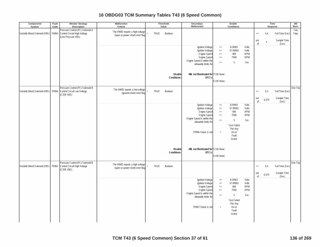
Component/ Fault Monitor Strategy Secondary MilSystem Code Description Malfunction Illum.Criteria Value Conditions Required
Malfunction Threshold Enable Time
Variable Bleed Solenoid (VBS) P0963Pressure Control (PC) Solenoid AControl Circuit High Voltage(Line Pressure VBS)
The HWIO reports a high voltage(open or power short) error flag = TRUE Boolean >= 4.4 Fail Time (Sec)
TwoTrips
outof 5 Sample Time
(Sec)Ignition Voltage >= 8.59961 VoltsIgnition Voltage <= 31.99902 Volts
Engine Speed >= 400 RPMEngine Speed <= 7500 RPM
Engine Speed is within theallowable limits for >= 5 Sec
DisableConditions:
MIL not Illuminated forDTC's:
Variable Bleed Solenoid (VBS) P0966Pressure Control (PC) Solenoid BControl Circuit Low Voltage(C35R VBS)
The HWIO reports a low voltage(ground short) error flag = TRUE Boolean >= 0.3 Fail Time (Sec)
One Trip
outof 0.375 Sample Time
(Sec)Ignition Voltage >= 8.59961 VoltsIgnition Voltage <= 31.99902 Volts
Engine Speed >= 400 RPMEngine Speed <= 7500 RPM
Engine Speed is within theallowable limits for >= 5 Sec
P0966 Status is not =
Test FailedThis Key
On orFaultActive
DisableConditions:
MIL not Illuminated forDTC's:
Variable Bleed Solenoid (VBS) P0967Pressure Control (PC) Solenoid BControl Circuit High Voltage(C35R VBS)
The HWIO reports a high voltage(open or power short) error flag = TRUE Boolean >= 0.3 Fail Time (Sec)
One Trip
outof 0.375 Sample Time
(Sec)Ignition Voltage >= 8.59961 VoltsIgnition Voltage <= 31.99902 Volts
Engine Speed >= 400 RPMEngine Speed <= 7500 RPM
Engine Speed is within theallowable limits for >= 5 Sec
P0967 Status is not =
Test FailedThis Key
On orFaultActive
TCM: None
ECM: None
TCM: None
ECM: None
16 OBDG03 TCM Summary Tables T43 (6 Speed Common)
TCM T43 (6 Speed Common) Section 37 of 61 136 of 269

Component/ Fault Monitor Strategy Secondary MilSystem Code Description Malfunction Illum.Criteria Value Conditions Required
Malfunction Threshold Enable Time
DisableConditions:
MIL not Illuminated forDTC's:
Variable Bleed Solenoid (VBS) P0970Pressure Control (PC) Solenoid CControl Circuit Low Voltage(C456/CBR1 VBS)
The HWIO reports a low voltage(ground short) error flag = TRUE Boolean >= 0.3 Fail Time (Sec)
One Trip
outof 0.375 Sample Time
(Sec)
P0970 Status is not =
Test FailedThis Key
On orFaultActive
Ignition Voltage >= 8.59961 VoltsIgnition Voltage <= 31.99902 Volts
Engine Speed >= 400 RPMEngine Speed <= 7500 RPM
Engine Speed is within theallowable limits for >= 5 Sec
DisableConditions:
MIL not Illuminated forDTC's:
Variable Bleed Solenoid (VBS) P0971Pressure Control (PC) Solenoid CControl Circuit High Voltage(C456/CBR1 VBS)
The HWIO reports a high voltage(open or power short) error flag = TRUE Boolean >= 0.3 Fail Time (Sec)
One Trip
outof 0.375 Sample Time
(Sec)
P0971 Status is not =
Test FailedThis Key
On orFaultActive
Ignition Voltage >= 8.59961 VoltsIgnition Voltage <= 31.99902 Volts
Engine Speed >= 400 RPMEngine Speed <= 7500 RPM
Engine Speed is within theallowable limits for >= 5 Sec
DisableConditions:
MIL not Illuminated forDTC's:
Shift Solinoid P0973 Shift Solenoid A Control Circuit Low(Mode 2 Solenoid)
The HWIO reports a low voltage(ground short) error flag = TRUE Boolean >= 1.2 Fail Time (Sec) One Trip
outof 1.5 Sample Time
(Sec)
P0973 Status is not =
Test FailedThis Key
On orFaultActive
TCM: None
ECM: None
TCM: None
ECM: None
TCM: None
ECM: None
16 OBDG03 TCM Summary Tables T43 (6 Speed Common)
TCM T43 (6 Speed Common) Section 38 of 61 137 of 269

Component/ Fault Monitor Strategy Secondary MilSystem Code Description Malfunction Illum.Criteria Value Conditions Required
Malfunction Threshold Enable Time
Ignition Voltage >= 8.59961 VoltsIgnition Voltage <= 31.99902 Volts
Engine Speed >= 400 RPMEngine Speed <= 7500 RPM
Engine Speed is within theallowable limits for >= 5 Sec
DisableConditions:
MIL not Illuminated forDTC's:
Shift Solinoid P0974 Shift Solenoid A Control Circuit High(Mode 2 Solenoid)
The HWIO reports a high voltage(open or power short) error flag = TRUE Boolean >= 1.2 Fail Time (Sec) Two
Tripsoutof 1.5 Sample Time
(Sec)
P0974 Status is not =
Test FailedThis Key
On orFaultActive
Ignition Voltage >= 8.59961 VoltsIgnition Voltage <= 31.99902 Volts
Engine Speed >= 400 RPMEngine Speed <= 7500 RPM
Engine Speed is within theallowable limits for >= 5 Sec
DisableConditions:
MIL not Illuminated forDTC's:
Mode 3 Multiplex Valve P0977 Shift Solenoid B Control Circuit High(Mode 3 Solenoid)
The HWIO reports a high voltage(open or power short) error flag = TRUE Boolean >= 1.2 Sec One Trip
outof 1.5 Sec
P0977 Status is not =
Test FailedThis Key
On orFaultActive
Ignition Voltage >= 8.59961 VoltsIgnition Voltage <= 31.99902 Volts
Engine Speed >= 400 RPMEngine Speed <= 7500 RPM
Engine Speed is within theallowable limits for >= 5 Sec
DisableConditions:
MIL not Illuminated forDTC's:
TCM: None
ECM: None
TCM: None
ECM: None
TCM: None
ECM: None
16 OBDG03 TCM Summary Tables T43 (6 Speed Common)
TCM T43 (6 Speed Common) Section 39 of 61 138 of 269

Component/ Fault Monitor Strategy Secondary MilSystem Code Description Malfunction Illum.Criteria Value Conditions Required
Malfunction Threshold Enable Time
Tap Up Tap Down Switch(TUTD) P1761 Tap Up and Down switch signal
circuit (rolling count)
Rolling count value received fromBCM does not match expected
value= TRUE Boolean >= 3 Fail Counter
SpecialNo MIL
> 10 Sample Timer(Sec)
Tap Up Tap Down MessageHealth = TRUE Boolean
Engine Speed Lo >= 400 RPMEngine Speed Hi <= 7500 RPM
Engine Speed is within theallowable limits for >= 5 Sec
DisableConditions:
MIL not Illuminated forDTC's:
Tap Up Tap Down Switch(TUTD) P1765 Upshift Switch Circuit #2 Fail Case 1 Tap Up Switch Stuck in the Up
Position in Range 1 Enabled = 0 Boolean SpecialNo MIL
Tap Up Switch Stuck in the UpPosition in Range 2 Enabled = 0 Boolean
Tap Up Switch Stuck in the UpPosition in Range 3 Enabled = 0 Boolean
Tap Up Switch Stuck in the UpPosition in Range 4 Enabled = 0 Boolean
Tap Up Switch Stuck in the UpPosition in Range 5 Enabled = 0 Boolean
Tap Up Switch Stuck in the UpPosition in Range 6 Enabled = 0 Boolean
Tap Up Switch Stuck in the UpPosition in Neutral Enabled = 1 Boolean
Tap Up Switch Stuck in the UpPosition in Park Enabled = 1 Boolean
Tap Up Switch Stuck in the UpPosition in Reverse Enabled = 0 Boolean
Tap Up Switch ON = TRUE Boolean >= 1 Fail Time (Sec)
Fail Case 2 Tap Up Switch Stuck in the UpPosition in Range 1 Enabled = 1 Boolean
Tap Up Switch Stuck in the UpPosition in Range 2 Enabled = 1 Boolean
Tap Up Switch Stuck in the UpPosition in Range 3 Enabled = 1 Boolean
Tap Up Switch Stuck in the UpPosition in Range 4 Enabled = 1 Boolean
Tap Up Switch Stuck in the UpPosition in Range 5 Enabled = 1 Boolean
Tap Up Switch Stuck in the UpPosition in Range 6 Enabled = 1 Boolean
Tap Up Switch Stuck in the UpPosition in Neutral Enabled = 0 Boolean
Tap Up Switch Stuck in the UpPosition in Park Enabled = 0 Boolean
Tap Up Switch Stuck in the UpPosition in Reverse Enabled = 0 Boolean
Tap Up Switch ON = TRUE Boolean
TCM: None
ECM: None
16 OBDG03 TCM Summary Tables T43 (6 Speed Common)
TCM T43 (6 Speed Common) Section 40 of 61 139 of 269

Component/ Fault Monitor Strategy Secondary MilSystem Code Description Malfunction Illum.Criteria Value Conditions Required
Malfunction Threshold Enable Time
NOTE: Both Failcase1 andFailcase 2 Must Be Met >= 600 Fail Time (Sec)
Time Since Last RangeChange >= 1 Enable Time
(Sec)Ignition Voltage Lo >= 8.59961 VoltsIgnition Voltage Hi <= 31.99902 VoltsEngine Speed Lo >= 400 RPMEngine Speed Hi <= 7500 RPM
Engine Speed is within theallowable limits for >= 5 Sec
P1765 Status is
Test FailedThis Key
On orFaultActive
DisableConditions:
MIL not Illuminated forDTC's:
Tap Up Tap Down Switch(TUTD) P1766 Downshift Switch Circuit #2
Fail Case 1 Tap Down Switch Stuck in theDown Position in Range 1 Enabled = 0 Boolean
SpecialNo MIL
Tap Down Switch Stuck in theDown Position in Range 2 Enabled = 0 Boolean
Tap Down Switch Stuck in theDown Position in Range 3 Enabled = 0 Boolean
Tap Down Switch Stuck in theDown Position in Range 4 Enabled = 0 Boolean
Tap Down Switch Stuck in theDown Position in Range 5 Enabled = 0 Boolean
Tap Down Switch Stuck in theDown Position in Range 6 Enabled = 0 Boolean
Tap Down Switch Stuck in theDown Position in Range Neutral
Enabled= 1 Boolean
Tap Down Switch Stuck in theDown Position in Range Park
Enabled= 1 Boolean
Tap Down Switch Stuck in theDown Position in Range Reverse
Enabled= 0 Boolean
Tap Down Switch ON = TRUE Boolean >= 1 sec
Fail Case 2 Tap Down Switch Stuck in theDown Position in Range 1 Enabled = 1 Boolean
Tap Down Switch Stuck in theDown Position in Range 2 Enabled = 1 Boolean
TCM: P1767, P1761, P182E, P1915
ECM: None
16 OBDG03 TCM Summary Tables T43 (6 Speed Common)
TCM T43 (6 Speed Common) Section 41 of 61 140 of 269

Component/ Fault Monitor Strategy Secondary MilSystem Code Description Malfunction Illum.Criteria Value Conditions Required
Malfunction Threshold Enable Time
Tap Down Switch Stuck in theDown Position in Range 3 Enabled = 1 Boolean
Tap Down Switch Stuck in theDown Position in Range 4 Enabled = 1 Boolean
Tap Down Switch Stuck in theDown Position in Range 5 Enabled = 1 Boolean
Tap Down Switch Stuck in theDown Position in Range 6 Enabled = 1 Boolean
Tap Down Switch Stuck in theDown Position in Neutral Enabled = 0 Boolean
Tap Down Switch Stuck in theDown Position in Park Enabled = 0 Boolean
Tap Down Switch Stuck in theDown Position in Reverse Enabled = 0 Boolean
Tap Down Switch ON = TRUE BooleanNOTE: Both Failcase1 and
Failcase 2 Must Be Met >= 600 sec
Time Since Last RangeChange >= 1 Sec
Ignition Voltage Lo >= 8.59961 VoltsIgnition Voltage Hi <= 18 VoltsEngine Speed Lo >= 400 RPMEngine Speed Hi <= 7500 RPM
Engine Speed is within theallowable limits for >= 5 Sec
P1766 Status is
Test FailedThis Key
On orFaultActive
DisableConditions:
MIL not Illuminated forDTC's:
Tap Up Tap Down Switch(TUTD) P1767 Up and Down Shift Switch Circuit #2 TUTD Circuit Reads Invalid
Voltage = TRUE Boolean >= 60 Fail Time (Sec) SpecialNo MIL
Ignition Voltage Lo >= 8.59961 VoltsIgnition Voltage Hi <= 31.99902 VoltsEngine Speed Lo >= 400 RPMEngine Speed Hi <= 7500 RPM
Engine Speed is within theallowable limits for >= 5 Sec
P1767 Status is
Test FailedThis Key
On orFaultActive
TCM: P1767, P1761, P182E, P1915
ECM: None
16 OBDG03 TCM Summary Tables T43 (6 Speed Common)
TCM T43 (6 Speed Common) Section 42 of 61 141 of 269

Component/ Fault Monitor Strategy Secondary MilSystem Code Description Malfunction Illum.Criteria Value Conditions Required
Malfunction Threshold Enable Time
DisableConditions:
MIL not Illuminated forDTC's:
Internal Mode Switch (IMS) P182E Internal Mode Switch - Invalid RangeFail Case 1
Current range =Transition 1
(bit state1110)
RangeOne Trip
Previous rangeCeTRGR_e_PRNDL_Drive
6Range
Previous rangeCeTRGR_e_PRNDL_Drive
5Range
Range Shift State = Range ShiftCompleted ENUM
Absolute Attained Gear Slip <= 50 rpmAttained Gear <= SixthAttained Gear >= First
Throttle Position Available = TRUEThrottle Position >= 8.0002 pct
Output Speed >= 200 rpmEngine Torque >= 50 NmEngine Torque <= 8191.75 Nm
If the above conditions are metthen Increment Fail Timer >= 1 Fail Seconds
If Fail Timer has Expired thenIncrement Fail Counter >= 5 Fail Counts
Fail Case 2 Output Speed <= 70 rpmThe following PRNDL sequenceevents occur in this exact order:
PRNDL state = Drive 6 (bitstate 0110) Range
PRNDL state = Drive 6 for >= 1 Sec
PRNDL state =Transition 8
(bit state0111)
Range
PRNDL state = Drive 6 (bitstate 0110) Range
PRNDL state =Transition 1
(bit state1110)
Range
Above sequencing occurs in <= 1 SecNeutral Idle Mode = Inactive
If all conditions above are metIncrement delay Timer
If the below two conditions aremet Increment Fail Timer >= 3 Fail Seconds
delay timer >= 1 SecInput Speed >= 400 Sec
If Fail Timer has Expired thenIncrement Fail Counter >= 2 Fail Counts
Fail Case 3Current range =
Transition 13(bit state
0010)Range Previous range
CeTRGR_e_PRNDL_Drive5
Engine Torque >= -8192 Nm Previous rangeCeTRGR_e_PRNDL_Drive5
TCM: P1761
ECM: None
16 OBDG03 TCM Summary Tables T43 (6 Speed Common)
TCM T43 (6 Speed Common) Section 43 of 61 142 of 269

Component/ Fault Monitor Strategy Secondary MilSystem Code Description Malfunction Illum.Criteria Value Conditions Required
Malfunction Threshold Enable Time
Engine Torque <= 8191.75 Nm IMS is 7 position configuration = 0 Boolean
If the above conditions are metthen, Increment Fail Timer
If the "IMS 7 Position config" =1 then the "previous range"criteria above must also besatsified when the "current
range" = "Transition 13"
>= 0.225 Seconds
If Fail Timer has Expired thenIncrement Fail Counter >= 15 Fail Counts
Fail Case 4
Current range = Transition 8
(bit state0111)
RangeDisable Fail Case 4 if last
positive range was Drive 6 andcurrent range is transition 8
Inhibit bit (see definition) = FALSE
Set inhibit bit true if PRNDL =1100 (rev) or 0100 (Rev-Neu
transition 11)Set inhibit bit false if PRNDL =
1001 (park)Steady State Engine Torque >= 30 NmSteady State Engine Torque <= 8191.75 Nm
If the above conditions are metthen Increment Fail Timer >= 0.225 Seconds
If the above Condtions have beenmet, Increment Fail Counter >= 15 Fail Counts
Fail Case 5 Throttle Position Available = TRUE BooleanThe following PRNDL sequenceevents occur in this exact order:
PRNDL State = Reverse (bitstate 1100) Range
PRNDL State =Transition 11
(bit state0100)
Range
PRNDL State = Neutral (bitstate 0101) Range
PRNDL State =Transition 11
(bit state0100)
Range
Above sequencing occurs in <= 1 SecThen delay timer increments
Delay timer >= 5 sec
Range Shift State = Range ShiftComplete
Absolute Attained Gear Slip <= 50 rpmAttained Gear <= SixthAttained Gear >= First
Throttle Position >= 8.0002 pctOutput Speed >= 200 rpm
If the above conditions are metIncrement Fail Timer >= 20 Seconds
Fail Case 6Current range =
Illegal (bitstate 0000 or1000 or 0001)
A Open Circuit Definition (flagset false if the following
conditions are met):
and Current Range
Transition11 (bitstate0100)
A Open Circuit (See Definition) = FALSE Boolean or
16 OBDG03 TCM Summary Tables T43 (6 Speed Common)
TCM T43 (6 Speed Common) Section 44 of 61 143 of 269

Component/ Fault Monitor Strategy Secondary MilSystem Code Description Malfunction Illum.Criteria Value Conditions Required
Malfunction Threshold Enable Time
Last positive stateNeutral (bit
state0101)
or
Previous transition state Transition8 (bit state
0111)Fail case 5 delay timer = 0 sec
If the above Condtions are metthen, Increment Fail timer >= 6.25 Seconds
Fail Case 7 Current PRNDL State = PRNDL circuitABCP = 1101 Range
and
Previous PRNDL state = PRNDL circuitABCP =1111 Range
Input Speed >= 150 RPMReverse Trans Ratio <= 2.97595 ratioReverse Trans Ratio >= 3.42395 ratio
If the above Condtions are metthen, Increment Fail timer >= 6.25 Seconds
P182E will report test fail whenany of the above 7 fail cases are
met
Ignition Voltage Lo >= 8.59961 VoltsIgnition Voltage Hi <= 31.99902 VoltsEngine Speed Lo >= 400 RPMEngine Speed Hi <= 7500 RPM
Engine Speed is within theallowable limits for >= 5 Sec
Engine Torque Signal Valid = TRUE Boolean
DisableConditions:
MIL not Illuminated forDTC's:
Tap Up Tap Down Switch(TUTD) P1876 Tap Up and Down Enable Switch
Circuit Current range =Park or
Reverse orNeutral
Range StateSpecialNo MIL
TUTD Enable Switch is Active = TRUE Boolean>= 3 Fail Time (Sec)>= 5 Fail Counts
Ignition Voltage Lo >= 8.59961 VoltsIgnition Voltage Hi <= 31.99902 VoltsVehicle Speed Lo <= 511 KPHEngine Speed Lo >= 400 RPMEngine Speed Hi <= 7500 RPM
TCM: P0716, P0717, P0722, P0723,P07C0, P07BF, P077C, P077D
ECM: P0101, P0102, P0103, P0106,P0107, P0108, P0171, P0172, P0174,P0175, P0201, P0202, P0203, P0204,P0205, P0206, P0207, P0208, P0300,P0301, P0302, P0303, P0304, P0305,P0306, P0307, P0308, P0401, P042E
16 OBDG03 TCM Summary Tables T43 (6 Speed Common)
TCM T43 (6 Speed Common) Section 45 of 61 144 of 269
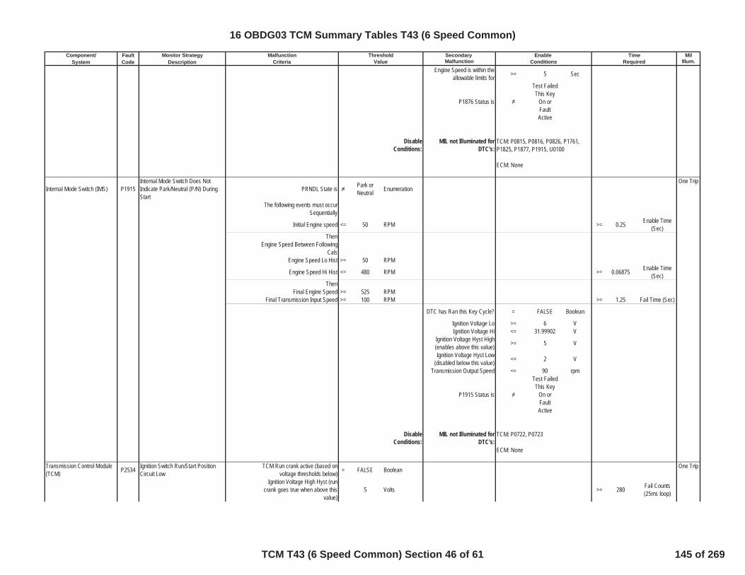
Component/ Fault Monitor Strategy Secondary MilSystem Code Description Malfunction Illum.Criteria Value Conditions Required
Malfunction Threshold Enable Time
Engine Speed is within theallowable limits for >= 5 Sec
P1876 Status is
Test FailedThis Key
On orFaultActive
DisableConditions:
MIL not Illuminated forDTC's:
Internal Mode Switch (IMS) P1915Internal Mode Switch Does NotIndicate Park/Neutral (P/N) DuringStart
PRNDL State is Park orNeutral Enumeration
One Trip
The following events must occurSequentially
Initial Engine speed <= 50 RPM >= 0.25 Enable Time(Sec)
ThenEngine Speed Between Following
CalsEngine Speed Lo Hist >= 50 RPM
Engine Speed Hi Hist <= 480 RPM >= 0.06875 Enable Time(Sec)
ThenFinal Engine Speed >= 525 RPM
Final Transmission Input Speed >= 100 RPM >= 1.25 Fail Time (Sec)
DTC has Ran this Key Cycle? = FALSE Boolean
Ignition Voltage Lo >= 6 VIgnition Voltage Hi <= 31.99902 V
Ignition Voltage Hyst High(enables above this value) >= 5 V
Ignition Voltage Hyst Low(disabled below this value) <= 2 V
Transmission Output Speed <= 90 rpm
P1915 Status is
Test FailedThis Key
On orFaultActive
DisableConditions:
MIL not Illuminated forDTC's:
Transmission Control Module(TCM) P2534 Ignition Switch Run/Start Position
Circuit LowTCM Run crank active (based on
voltage thresholds below) = FALSE Boolean One Trip
Ignition Voltage High Hyst (runcrank goes true when above this
value)5 Volts >= 280 Fail Counts
(25ms loop)
TCM: P0815, P0816, P0826, P1761,P1825, P1877, P1915, U0100
ECM: None
TCM: P0722, P0723
ECM: None
16 OBDG03 TCM Summary Tables T43 (6 Speed Common)
TCM T43 (6 Speed Common) Section 46 of 61 145 of 269

Component/ Fault Monitor Strategy Secondary MilSystem Code Description Malfunction Illum.Criteria Value Conditions Required
Malfunction Threshold Enable Time
Ignition Voltage Low Hyst (runcrank goes false when below this
value)2 Volts Out
of 280 Sample Counts(25ms loop)
ECM run/crank active statusavailable = TRUE Boolean
ECM run/crank active status = TRUE Boolean
DisableConditions:
MIL not Illuminated forDTC's:
Transmission Control Module(TCM) P2535 Ignition Switch Run/Start Position
Circuit HighTCM Run crank active (based on
voltage thresholds below) = TRUE Boolean One Trip
Ignition Voltage High Hyst (runcrank goes true when above this
value)5 Volts >= 280 Fail Counts
(25ms loop)
Ignition Voltage Low Hyst (runcrank goes false when below this
value)2 Volts Out
of 280 Sample Counts(25ms loop)
ECM run/crank active statusavailable = TRUE Boolean
ECM run/crank active status = FALSE Boolean
DisableConditions:
MIL not Illuminated forDTC's:
Variable Bleed Solenoid (VBS) P2714 Pressure Control (PC) Solenoid DStuck Off [CB26]
Fail Case 1 Case: Steady State 2nd Gear One Trip
Gear slip >= 400 RPM >=
Please SeeTable 5 For
Neutral TimeCal
Neutral Timer(Sec)
Intrusive test:commanded 3rd gear
If attained Gear = 3rd for Time >=
Table BasedTime Please
see Table 2 inSupportingDocuments
Enable Time(Sec)
If Above Conditions have beenmet
Increment 2nd gear fail count >= 3 2nd Gear FailCount
or
and CB26 Fail Count >= 14 CB26 FailCount
Fail Case 2 Case: Steady State 6th Gear
Gear slip >= 400 RPM >=
Please SeeTable 5 For
Neutral TimeCal
Neutral Timer(Sec)
Intrusive test:commanded 5th gear
TCM: None
ECM: None
TCM: None
ECM: None
16 OBDG03 TCM Summary Tables T43 (6 Speed Common)
TCM T43 (6 Speed Common) Section 47 of 61 146 of 269
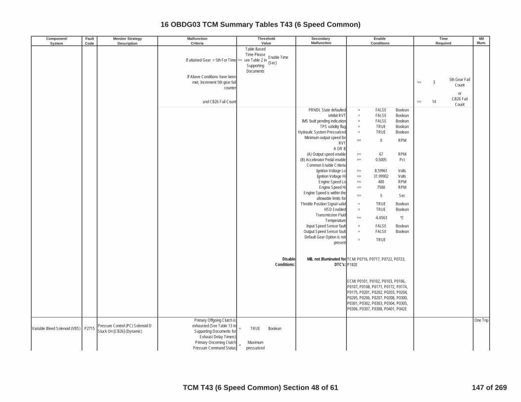
Component/ Fault Monitor Strategy Secondary MilSystem Code Description Malfunction Illum.Criteria Value Conditions Required
Malfunction Threshold Enable Time
If attained Gear = 5th For Time >=
Table BasedTime Please
see Table 2 inSupportingDocuments
Enable Time(Sec)
If Above Conditions have beenmet, Increment 5th gear fail
counter>= 3 5th Gear Fail
Count
or
and CB26 Fail Count >= 14 CB26 FailCount
PRNDL State defaulted = FALSE Booleaninhibit RVT = FALSE Boolean
IMS fault pending indication = FALSE BooleanTPS validity flag = TRUE Boolean
Hydraulic System Pressurized = TRUE BooleanMinimum output speed for
RVT >= 0 RPM
A OR B(A) Output speed enable >= 67 RPM
(B) Accelerator Pedal enable >= 0.5005 PctCommon Enable Criteria
Ignition Voltage Lo >= 8.59961 VoltsIgnition Voltage Hi <= 31.99902 VoltsEngine Speed Lo >= 400 RPMEngine Speed Hi <= 7500 RPM
Engine Speed is within theallowable limits for >= 5 Sec
Throttle Position Signal valid = TRUE BooleanHSD Enabled = TRUE Boolean
Transmission FluidTemperature >= -6.6563 ºC
Input Speed Sensor fault = FALSE BooleanOutput Speed Sensor fault = FALSE BooleanDefault Gear Option is not
present = TRUE
DisableConditions:
MIL not Illuminated forDTC's:
Variable Bleed Solenoid (VBS) P2715 Pressure Control (PC) Solenoid DStuck On [CB26] (Dynamic)
Primary Offgoing Clutch isexhausted (See Table 13 in
Supporting Documents forExhaust Delay Timers)
= TRUE Boolean
One Trip
Primary Oncoming ClutchPressure Command Status = Maximum
pressurized
TCM: P0716, P0717, P0722, P0723,P182E
ECM: P0101, P0102, P0103, P0106,P0107, P0108, P0171, P0172, P0174,P0175, P0201, P0202, P0203, P0204,P0205, P0206, P0207, P0208, P0300,P0301, P0302, P0303, P0304, P0305,P0306, P0307, P0308, P0401, P042E
16 OBDG03 TCM Summary Tables T43 (6 Speed Common)
TCM T43 (6 Speed Common) Section 48 of 61 147 of 269

Component/ Fault Monitor Strategy Secondary MilSystem Code Description Malfunction Illum.Criteria Value Conditions Required
Malfunction Threshold Enable Time
Primary Offgoing Clutch PressureCommand Status =
Clutchexhaust
command
Range Shift Status Initial ClutchControl
Attained Gear Slip <= 40 RPM
If above coditons are true,increment appropriate Fail 1
Timers Below:fail timer 1
(2-1 shifting with throttle) >= 0.2998 Fail Time (Sec)
fail timer 1(2-1 shifting without throttle) >= 0.5 Fail Time (Sec)
fail timer 1(2-3 shifting with throttle) >= 0.2998 Fail Time (Sec)
fail timer 1(2-3 shifting without throttle) >= 0.5 Fail Time (Sec)
fail timer 1(2-4 shifting with throttle) >= 0.2998 Fail Time (Sec)
fail timer 1(2-4 shifting without throttle) >= 0.5 Fail Time (Sec)
fail timer 1(6-4 shifting with throttle) >= 0.2998 Fail Time (Sec)
fail timer 1(6-4 shifting without throttle) >= 0.5 Fail Time (Sec)
fail timer 1(6-5 shifting with throttle) >= 0.2998 Fail Time (Sec)
fail timer 1(6-5 shifting without throttle) >= 0.5 Fail Time (Sec)
If Attained Gear Slip is Less thanAbove Cal Increment Fail Timers >=
Total FailTime = (Fail 1+ Fail 2) See
EnableTimers for FailTimer 1, andReferenceSupportingTable 15 forFail Timer 2
sec
If fail timer is greater thanthreshold increment corresponding
gear fail counter and total failcounter
2nd gear fail counter >= 3 Fail CounterFrom 2nd Gear
OR
6th gear fail counter >= 3 Fail CounterFrom 6th Gear
OR
total fail counter >= 5 Total FailCounter
TUT Enable temperature >= -6.6563 ºCInput Speed Sensor fault = FALSE Boolean
Output Speed Sensor fault = FALSE Boolean
16 OBDG03 TCM Summary Tables T43 (6 Speed Common)
TCM T43 (6 Speed Common) Section 49 of 61 148 of 269

Component/ Fault Monitor Strategy Secondary MilSystem Code Description Malfunction Illum.Criteria Value Conditions Required
Malfunction Threshold Enable Time
Command / Attained Gear 1st BooleanHigh Side Driver ON = TRUE Boolean
output speed limit for TUT >= 100 RPMinput speed limit for TUT >= 150 RPM
PRNDL state defaulted = FALSE BooleanIMS Fault Pending = FALSE Boolean
Service Fast Learn Mode = FALSE BooleanHSD Enabled = TRUE Boolean
DisableConditions:
MIL not Illuminated forDTC's:
Variable Bleed Solenoid (VBS) P2715 Pressure Control (PC) Solenoid DStuck On [CB26] (Steady State)
Fail Case 1 Case: Steady State 1st One Trip
Attained Gear slip >= 400 RPM
If the Above is True for Time >=
Table BasedTime Please
Refer to Table4 in
supportingdocuments
Enable Time(Sec)
Intrusive test:(CBR1 clutch exhausted)
Gear Ratio <= 2.48218Gear Ratio >= 2.24585
If the above parameters are true
>= 1.1 Fail Timer (Sec)
>= 5 Fail Count in1st Gear
or
>= 5 Total FailCounts
Fail Case 2 Case: Steady State 3rd Gear
Max Delta Output SpeedHysteresis >=
Table Basedvalue PleaseRefer to 3DTable 1 insupportingdocuments
rpm/sec
Min Delta Output SpeedHysteresis >=
Table Basedvalue PleaseRefer to 3DTable 2 insupportingdocuments
rpm/sec
TCM: P0716, P0717, P0722, P0723,P182E
ECM: P0101, P0102, P0103, P0106,P0107, P0108, P0171, P0172, P0174,P0175, P0201, P0202, P0203, P0204,P0205, P0206, P0207, P0208, P0300,P0301, P0302, P0303, P0304, P0305,P0306, P0307, P0308, P0401, P042E
16 OBDG03 TCM Summary Tables T43 (6 Speed Common)
TCM T43 (6 Speed Common) Section 50 of 61 149 of 269

Component/ Fault Monitor Strategy Secondary MilSystem Code Description Malfunction Illum.Criteria Value Conditions Required
Malfunction Threshold Enable Time
If the Above is True for Time >=
Table BasedTime Please
Refer to Table17 in
supportingdocuments
Sec
Intrusive test: (C35R clutch exhausted)
Gear Ratio <= 2.48218Gear Ratio >= 2.24585
If the above parameters are true
>= 1.1 Fail Timer (Sec)
>= 3 Fail Count in3rd Gear
or
>= 5 Total FailCounts
Fail Case 3 Case: Steady State 4rd Gear
Max Delta Output SpeedHysteresis >=
Table Basedvalue PleaseRefer to 3DTable 1 insupportingdocuments
rpm/sec
Min Delta Output SpeedHysteresis >=
Table Basedvalue PleaseRefer to 3DTable 2 insupportingdocuments
rpm/sec
If the Above is True for Time >=
Table BasedTime Please
Refer to Table17 in
supportingdocuments
Sec
Intrusive test: (C1234 clutch exhausted)
Gear Ratio <= 0.70032Gear Ratio >= 0.63367
If the above parameters are true
>= 1.1 Fail Timer (Sec)
>= 3 Fail Count in4th Gear
or
>= 5 Total FailCounts
Fail Case 4 Case: Steady State 5th Gear
Max Delta Output SpeedHysteresis >=
Table Basedvalue PleaseRefer to 3DTable 1 insupportingdocuments
rpm/sec
16 OBDG03 TCM Summary Tables T43 (6 Speed Common)
TCM T43 (6 Speed Common) Section 51 of 61 150 of 269
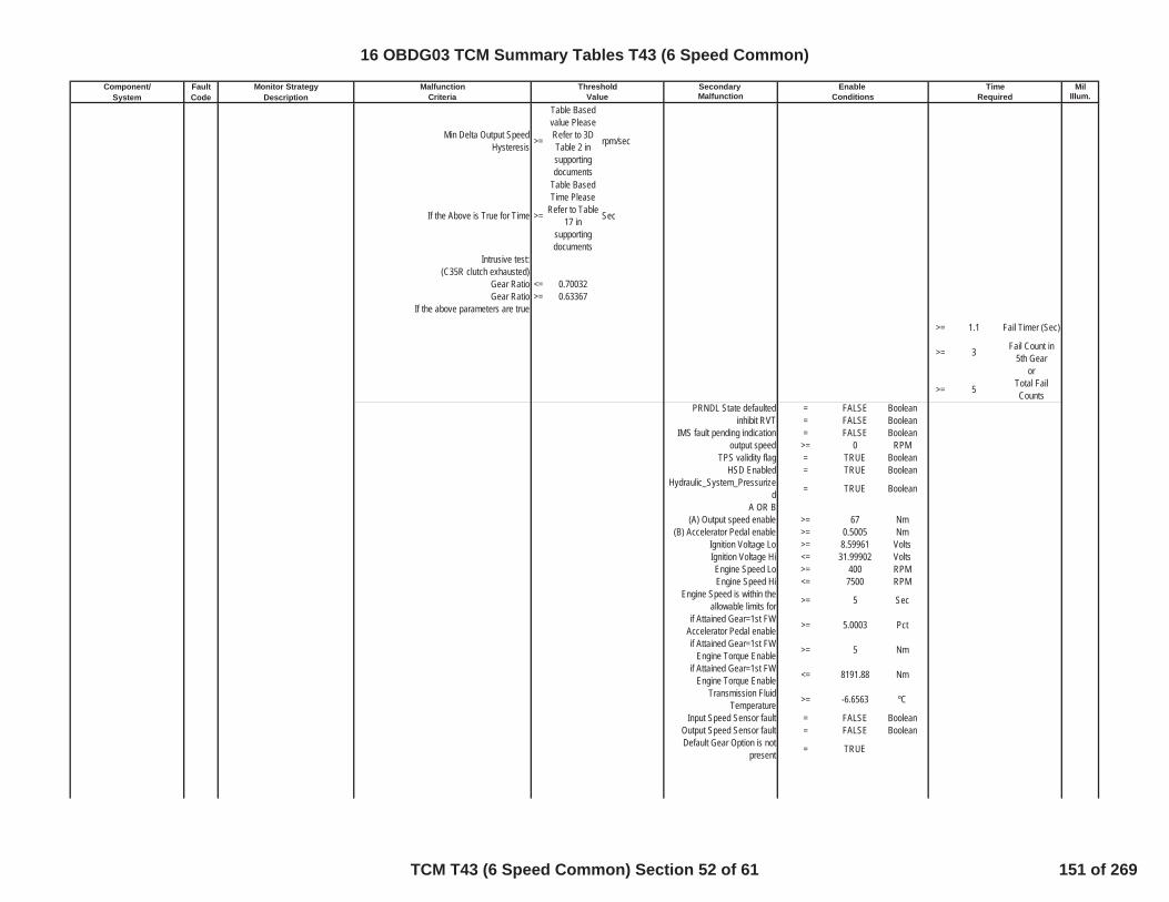
Component/ Fault Monitor Strategy Secondary MilSystem Code Description Malfunction Illum.Criteria Value Conditions Required
Malfunction Threshold Enable Time
Min Delta Output SpeedHysteresis >=
Table Basedvalue PleaseRefer to 3DTable 2 insupportingdocuments
rpm/sec
If the Above is True for Time >=
Table BasedTime Please
Refer to Table17 in
supportingdocuments
Sec
Intrusive test: (C35R clutch exhausted)
Gear Ratio <= 0.70032Gear Ratio >= 0.63367
If the above parameters are true
>= 1.1 Fail Timer (Sec)
>= 3 Fail Count in5th Gear
or
>= 5 Total FailCounts
PRNDL State defaulted = FALSE Booleaninhibit RVT = FALSE Boolean
IMS fault pending indication = FALSE Booleanoutput speed >= 0 RPM
TPS validity flag = TRUE BooleanHSD Enabled = TRUE Boolean
Hydraulic_System_Pressurized = TRUE Boolean
A OR B(A) Output speed enable >= 67 Nm
(B) Accelerator Pedal enable >= 0.5005 NmIgnition Voltage Lo >= 8.59961 VoltsIgnition Voltage Hi <= 31.99902 VoltsEngine Speed Lo >= 400 RPMEngine Speed Hi <= 7500 RPM
Engine Speed is within theallowable limits for >= 5 Sec
if Attained Gear=1st FWAccelerator Pedal enable >= 5.0003 Pct
if Attained Gear=1st FWEngine Torque Enable >= 5 Nm
if Attained Gear=1st FWEngine Torque Enable <= 8191.88 Nm
Transmission FluidTemperature >= -6.6563 ºC
Input Speed Sensor fault = FALSE BooleanOutput Speed Sensor fault = FALSE BooleanDefault Gear Option is not
present = TRUE
16 OBDG03 TCM Summary Tables T43 (6 Speed Common)
TCM T43 (6 Speed Common) Section 52 of 61 151 of 269
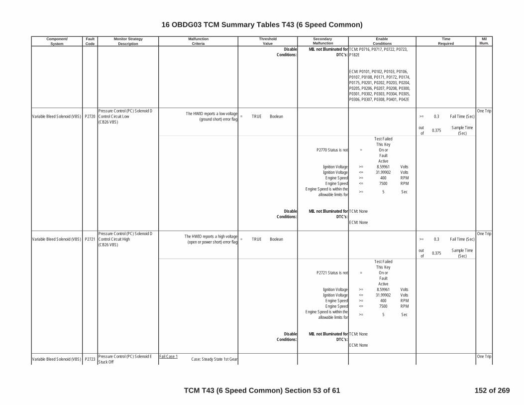
Component/ Fault Monitor Strategy Secondary MilSystem Code Description Malfunction Illum.Criteria Value Conditions Required
Malfunction Threshold Enable Time
DisableConditions:
MIL not Illuminated forDTC's:
Variable Bleed Solenoid (VBS) P2720Pressure Control (PC) Solenoid DControl Circuit Low(CB26 VBS)
The HWIO reports a low voltage(ground short) error flag = TRUE Boolean >= 0.3 Fail Time (Sec)
One Trip
outof 0.375 Sample Time
(Sec)
P2770 Status is not =
Test FailedThis Key
On orFaultActive
Ignition Voltage >= 8.59961 VoltsIgnition Voltage <= 31.99902 Volts
Engine Speed >= 400 RPMEngine Speed <= 7500 RPM
Engine Speed is within theallowable limits for >= 5 Sec
DisableConditions:
MIL not Illuminated forDTC's:
Variable Bleed Solenoid (VBS) P2721Pressure Control (PC) Solenoid DControl Circuit High(CB26 VBS)
The HWIO reports a high voltage(open or power short) error flag = TRUE Boolean >= 0.3 Fail Time (Sec)
One Trip
outof 0.375 Sample Time
(Sec)
P2721 Status is not =
Test FailedThis Key
On orFaultActive
Ignition Voltage >= 8.59961 VoltsIgnition Voltage <= 31.99902 Volts
Engine Speed >= 400 RPMEngine Speed <= 7500 RPM
Engine Speed is within theallowable limits for >= 5 Sec
DisableConditions:
MIL not Illuminated forDTC's:
Variable Bleed Solenoid (VBS) P2723 Pressure Control (PC) Solenoid EStuck Off
Fail Case 1 Case: Steady State 1st Gear One Trip
TCM: None
ECM: None
TCM: P0716, P0717, P0722, P0723,P182E
ECM: P0101, P0102, P0103, P0106,P0107, P0108, P0171, P0172, P0174,P0175, P0201, P0202, P0203, P0204,P0205, P0206, P0207, P0208, P0300,P0301, P0302, P0303, P0304, P0305,P0306, P0307, P0308, P0401, P042E
TCM: None
ECM: None
16 OBDG03 TCM Summary Tables T43 (6 Speed Common)
TCM T43 (6 Speed Common) Section 53 of 61 152 of 269

Component/ Fault Monitor Strategy Secondary MilSystem Code Description Malfunction Illum.Criteria Value Conditions Required
Malfunction Threshold Enable Time
Gear slip >= 400 RPM >=
Please SeeTable 5 For
Neutral TimeCal
Neutral Timer(Sec)
Intrusive test:commanded 2nd gear
If attained Gear 2nd for Time >=
Please referto Table 3 inSupportingDocuments
Shift Time (Sec)
If Above Conditions have beenmet, Increment 1st gear fail
counter>= 3 1st Gear Fail
Count
or
and C1234 fail counter >= 14 C1234 ClutchFail Count
Fail Case 2 Case: Steady State 2nd Gear
Gear slip >= 400 RPM >=
Please SeeTable 5 For
Neutral TimeCal
Neutral Timer(Sec)
Intrusive test:commanded 3rd gear
If attained Gear 3rd for Time >=
Please referto Table 3 inSupportingDocuments
Shift Time (Sec)
If Above Conditions have beenmet, Increment 2nd gear fail
counter>= 3 2nd Gear Fail
Count
or
and C1234 fail counter >= 14 C1234 ClutchFail Count
Fail Case 3 Case: Steady State 3rd Gear
Gear slip >= 400 RPM >=
Please SeeTable 5 For
Neutral TimeCal
Neutral Timer(Sec)
Intrusive test:commanded 4th gear
If attained Gear 4th for time >=
Please referto Table 3 inSupportingDocuments
Shift Time (Sec)
If Above Conditions have beenmet, Increment 3rd gear fail
counter>= 3 3rd Gear Fail
Count
or
and C1234 fail counter >= 14 C1234 ClutchFail Count
Fail Case 4 Case: Steady State 4th Gear
Gear slip >= 400 RPM >=
Please SeeTable 5 For
Neutral TimeCal
Neutral Timer(Sec)
Intrusive test:commanded 5th gear
16 OBDG03 TCM Summary Tables T43 (6 Speed Common)
TCM T43 (6 Speed Common) Section 54 of 61 153 of 269
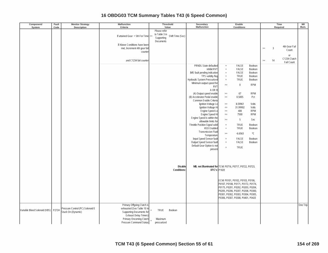
Component/ Fault Monitor Strategy Secondary MilSystem Code Description Malfunction Illum.Criteria Value Conditions Required
Malfunction Threshold Enable Time
If attained Gear = 5th For Time >=
Please referto Table 3 inSupportingDocuments
Shift Time (Sec)
If Above Conditions have beenmet, Increment 4th gear fail
counter>= 3 4th Gear Fail
Count
or
and C1234 fail counter >= 14 C1234 ClutchFail Count
PRNDL State defaulted = FALSE Booleaninhibit RVT = FALSE Boolean
IMS fault pending indication = FALSE BooleanTPS validity flag = TRUE Boolean
Hydraulic System Pressurized = TRUE BooleanMinimum output speed for
RVT >= 0 RPM
A OR B(A) Output speed enable >= 67 RPM
(B) Accelerator Pedal enable >= 0.5005 PctCommon Enable Criteria
Ignition Voltage Lo >= 8.59961 VoltsIgnition Voltage Hi <= 31.99902 VoltsEngine Speed Lo >= 400 RPMEngine Speed Hi <= 7500 RPM
Engine Speed is within theallowable limits for >= 5 Sec
Throttle Position Signal valid = TRUE BooleanHSD Enabled = TRUE Boolean
Transmission FluidTemperature >= -6.6563 ºC
Input Speed Sensor fault = FALSE BooleanOutput Speed Sensor fault = FALSE BooleanDefault Gear Option is not
present = TRUE
DisableConditions:
MIL not Illuminated forDTC's:
Variable Bleed Solenoid (VBS) P2724 Pressure Control (PC) Solenoid EStuck On (Dynamic)
Primary Offgoing Clutch isexhausted (See Table 10 in
Supporting Documents forExhaust Delay Timers)
= TRUE Boolean
One Trip
Primary Oncoming ClutchPressure Command Status = Maximum
pressurized
TCM: P0716, P0717, P0722, P0723,P182E
ECM: P0101, P0102, P0103, P0106,P0107, P0108, P0171, P0172, P0174,P0175, P0201, P0202, P0203, P0204,P0205, P0206, P0207, P0208, P0300,P0301, P0302, P0303, P0304, P0305,P0306, P0307, P0308, P0401, P042E
16 OBDG03 TCM Summary Tables T43 (6 Speed Common)
TCM T43 (6 Speed Common) Section 55 of 61 154 of 269
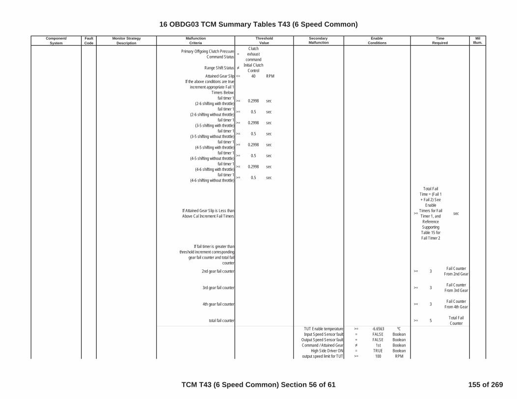
Component/ Fault Monitor Strategy Secondary MilSystem Code Description Malfunction Illum.Criteria Value Conditions Required
Malfunction Threshold Enable Time
Primary Offgoing Clutch PressureCommand Status =
Clutchexhaust
command
Range Shift Status Initial ClutchControl
Attained Gear Slip <= 40 RPMIf the above conditions are true
increment appropriate Fail 1Timers Below:
fail timer 1(2-6 shifting with throttle) >= 0.2998 sec
fail timer 1(2-6 shifting without throttle) >= 0.5 sec
fail timer 1(3-5 shifting with throttle) >= 0.2998 sec
fail timer 1(3-5 shifting without throttle) >= 0.5 sec
fail timer 1(4-5 shifting with throttle) >= 0.2998 sec
fail timer 1(4-5 shifting without throttle) >= 0.5 sec
fail timer 1(4-6 shifting with throttle) >= 0.2998 sec
fail timer 1(4-6 shifting without throttle) >= 0.5 sec
If Attained Gear Slip is Less thanAbove Cal Increment Fail Timers >=
Total FailTime = (Fail 1+ Fail 2) See
EnableTimers for FailTimer 1, andReferenceSupportingTable 15 forFail Timer 2
sec
If fail timer is greater thanthreshold increment corresponding
gear fail counter and total failcounter
2nd gear fail counter >= 3 Fail CounterFrom 2nd Gear
3rd gear fail counter >= 3 Fail CounterFrom 3rd Gear
4th gear fail counter >= 3 Fail CounterFrom 4th Gear
total fail counter >= 5 Total FailCounter
TUT Enable temperature >= -6.6563 ºCInput Speed Sensor fault = FALSE Boolean
Output Speed Sensor fault = FALSE BooleanCommand / Attained Gear 1st Boolean
High Side Driver ON = TRUE Booleanoutput speed limit for TUT >= 100 RPM
16 OBDG03 TCM Summary Tables T43 (6 Speed Common)
TCM T43 (6 Speed Common) Section 56 of 61 155 of 269

Component/ Fault Monitor Strategy Secondary MilSystem Code Description Malfunction Illum.Criteria Value Conditions Required
Malfunction Threshold Enable Time
input speed limit for TUT >= 150 RPMPRNDL state defaulted = FALSE Boolean
IMS Fault Pending = FALSE BooleanService Fast Learn Mode = FALSE Boolean
HSD Enabled = TRUE Boolean
DisableConditions:
MIL not Illuminated forDTC's:
Variable Bleed Solenoid (VBS) P2724 Pressure Control (PC) Solenoid EStuck On (Steady State)
Fail Case 1 Case: 5th Gear One Trip
Max Delta Output SpeedHysteresis >=
Table Basedvalue PleaseRefer to 3DTable 1 insupportingdocuments
rpm/sec
Min Delta Output SpeedHysteresis >=
Table Basedvalue PleaseRefer to 3DTable 2 insupportingdocuments
rpm/sec
If the Above is True for Time >=
Table BasedTime Please
Refer to Table17 in
supportingdocuments
Sec
Intrusive test:(C35R clutch exhausted)
Gear Ratio <= 1.20959Gear Ratio >= 1.09436
If the above parameters are true
>= 1.1 Fail Timer (Sec)
>= 3 Fail Count in5th Gear
OR
>= 3 Total FailCounts
Fail Case 2 Case: 6th Gear
Max Delta Output SpeedHysteresis >=
Table Basedvalue PleaseRefer to 3DTable 1 insupportingdocuments
rpm/sec
TCM: P0716, P0717, P0722, P0723,P182E
ECM: P0101, P0102, P0103, P0106,P0107, P0108, P0171, P0172, P0174,P0175, P0201, P0202, P0203, P0204,P0205, P0206, P0207, P0208, P0300,P0301, P0302, P0303, P0304, P0305,P0306, P0307, P0308, P0401, P042E
16 OBDG03 TCM Summary Tables T43 (6 Speed Common)
TCM T43 (6 Speed Common) Section 57 of 61 156 of 269

Component/ Fault Monitor Strategy Secondary MilSystem Code Description Malfunction Illum.Criteria Value Conditions Required
Malfunction Threshold Enable Time
Min Delta Output SpeedHysteresis >=
Table Basedvalue PleaseRefer to 3DTable 2 insupportingdocuments
rpm/sec
If the Above is True for Time >=
Table BasedTime Please
Refer to Table17 in
supportingdocuments
Sec
Intrusive test:(CB26 clutch exhausted)
Gear Ratio <= 1.20959Gear Ratio >= 1.09436
If the above parameters are true
>= 1.1 Fail Timer (Sec)
>= 3 Fail Count in6th Gear
OR
>= 3 Total FailCounts
PRNDL State defaulted = FALSE Booleaninhibit RVT = FALSE Boolean
IMS fault pending indication = FALSE Booleanoutput speed >= 0 RPM
TPS validity flag = TRUE BooleanHSD Enabled = TRUE Boolean
Hydraulic_System_Pressurized = TRUE Boolean
A OR B(A) Output speed enable >= 67 Nm
(B) Accelerator Pedal enable >= 0.5005 NmIgnition Voltage Lo >= 8.59961 VoltsIgnition Voltage Hi <= 31.99902 VoltsEngine Speed Lo >= 400 RPMEngine Speed Hi <= 7500 RPM
Engine Speed is within theallowable limits for >= 5 Sec
if Attained Gear=1st FWAccelerator Pedal enable >= 5.0003 Pct
if Attained Gear=1st FWEngine Torque Enable >= 5 Nm
if Attained Gear=1st FWEngine Torque Enable <= 8191.88 Nm
Transmission FluidTemperature >= -6.6563 ºC
Input Speed Sensor fault = FALSE BooleanOutput Speed Sensor fault = FALSE BooleanDefault Gear Option is not
present = TRUE
16 OBDG03 TCM Summary Tables T43 (6 Speed Common)
TCM T43 (6 Speed Common) Section 58 of 61 157 of 269

Component/ Fault Monitor Strategy Secondary MilSystem Code Description Malfunction Illum.Criteria Value Conditions Required
Malfunction Threshold Enable Time
DisableConditions:
MIL not Illuminated forDTC's:
Variable Bleed Solenoid (VBS) P2729Pressure Control (PC) Solenoid EControl Circuit Low(C1234 VBS)
The HWIO reports a low voltage(ground short) error flag = TRUE Boolean >= 0.3 Fail Time (Sec)
One Trip
outof 0.375 Sample Time
(Sec)
P2729 Status is not =
Test FailedThis Key
On orFaultActive
Ignition Voltage >= 8.59961 VoltIgnition Voltage <= 31.99902 Volt
Engine Speed >= 400 RPMEngine Speed <= 7500 RPM
Engine Speed is within theallowable limits for >= 5 Sec
DisableConditions:
MIL not Illuminated forDTC's:
Variable Bleed Solenoid (VBS) P2730Pressure Control (PC) Solenoid EControl Circuit High(C1234 VBS)
The HWIO reports a high voltage(open or power short) error flag = TRUE Boolean >= 0.3 Fail Time (Sec)
One Trip
outof 0.375 Sample Time
(Sec)
P2730 Status is not =
Test FailedThis Key
On orFaultActive
Ignition Voltage >= 8.59961 VoltIgnition Voltage <= 31.99902 Volt
Engine Speed >= 400 RPMEngine Speed <= 7500 RPM
Engine Speed is within theallowable limits for >= 5 Sec
DisableConditions:
MIL not Illuminated forDTC's:
TCM: P0716, P0717, P0722, P0723,P182E
ECM: P0101, P0102, P0103, P0106,P0107, P0108, P0171, P0172, P0174,P0175, P0201, P0202, P0203, P0204,P0205, P0206, P0207, P0208, P0300,P0301, P0302, P0303, P0304, P0305,P0306, P0307, P0308, P0401, P042E
TCM: None
ECM: None
TCM: None
ECM: None
16 OBDG03 TCM Summary Tables T43 (6 Speed Common)
TCM T43 (6 Speed Common) Section 59 of 61 158 of 269
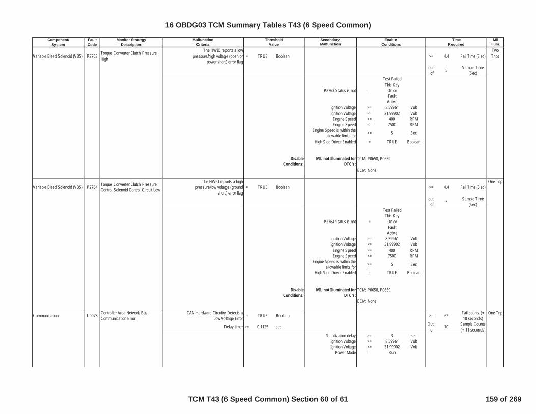
Component/ Fault Monitor Strategy Secondary MilSystem Code Description Malfunction Illum.Criteria Value Conditions Required
Malfunction Threshold Enable Time
Variable Bleed Solenoid (VBS) P2763 Torque Converter Clutch PressureHigh
The HWIO reports a lowpressure/high voltage (open or
power short) error flag= TRUE Boolean >= 4.4 Fail Time (Sec)
TwoTrips
outof 5 Sample Time
(Sec)
P2763 Status is not =
Test FailedThis Key
On orFaultActive
Ignition Voltage >= 8.59961 VoltIgnition Voltage <= 31.99902 Volt
Engine Speed >= 400 RPMEngine Speed <= 7500 RPM
Engine Speed is within theallowable limits for >= 5 Sec
High Side Driver Enabled = TRUE Boolean
DisableConditions:
MIL not Illuminated forDTC's:
Variable Bleed Solenoid (VBS) P2764 Torque Converter Clutch PressureControl Solenoid Control Circuit Low
The HWIO reports a highpressure/low voltage (ground
short) error flag= TRUE Boolean >= 4.4 Fail Time (Sec)
One Trip
outof 5 Sample Time
(Sec)
P2764 Status is not =
Test FailedThis Key
On orFaultActive
Ignition Voltage >= 8.59961 VoltIgnition Voltage <= 31.99902 Volt
Engine Speed >= 400 RPMEngine Speed <= 7500 RPM
Engine Speed is within theallowable limits for >= 5 Sec
High Side Driver Enabled = TRUE Boolean
DisableConditions:
MIL not Illuminated forDTC's:
Communication U0073 Controller Area Network BusCommunication Error
CAN Hardware Circuitry Detects aLow Voltage Error = TRUE Boolean >= 62 Fail counts (
10 seconds)One Trip
Delay timer >= 0.1125 sec Outof 70 Sample Counts
11 seconds)Stabilization delay >= 3 sec
Ignition Voltage >= 8.59961 VoltIgnition Voltage <= 31.99902 Volt
Power Mode = Run
TCM: P0658, P0659
ECM: None
TCM: P0658, P0659
ECM: None
16 OBDG03 TCM Summary Tables T43 (6 Speed Common)
TCM T43 (6 Speed Common) Section 60 of 61 159 of 269
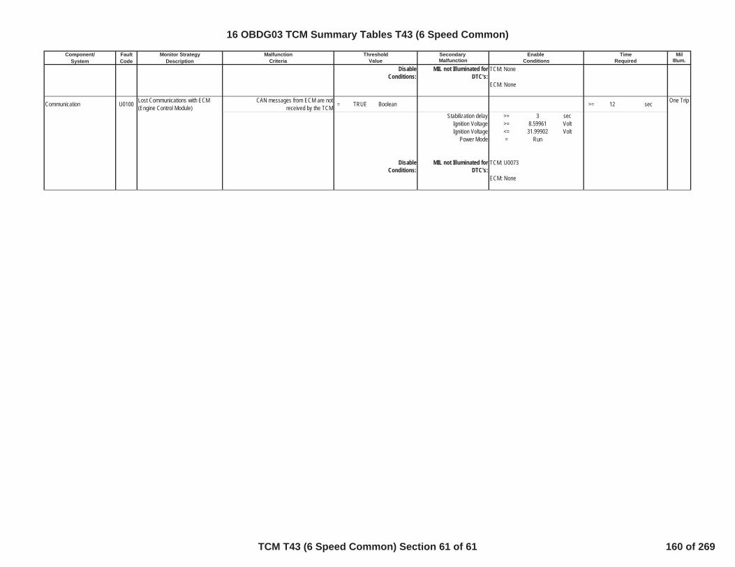
Component/ Fault Monitor Strategy Secondary MilSystem Code Description Malfunction Illum.Criteria Value Conditions Required
Malfunction Threshold Enable Time
DisableConditions:
MIL not Illuminated forDTC's:
Communication U0100 Lost Communications with ECM(Engine Control Module)
CAN messages from ECM are notreceived by the TCM = TRUE Boolean >= 12 sec One Trip
Stabilization delay >= 3 secIgnition Voltage >= 8.59961 VoltIgnition Voltage <= 31.99902 Volt
Power Mode = Run
DisableConditions:
MIL not Illuminated forDTC's:
TCM: None
ECM: None
TCM: U0073
ECM: None
16 OBDG03 TCM Summary Tables T43 (6 Speed Common)
TCM T43 (6 Speed Common) Section 61 of 61 160 of 269
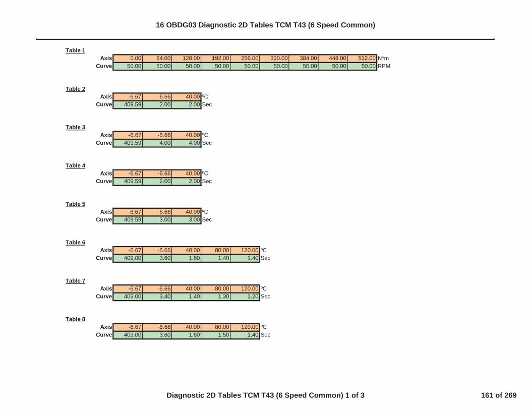
Table 1Axis 0.00 64.00 128.00 192.00 256.00 320.00 384.00 448.00 512.00 N*m
Curve 50.00 50.00 50.00 50.00 50.00 50.00 50.00 50.00 50.00 RPM
Table 2Axis -6.67 -6.66 40.00 ºC
Curve 409.59 2.00 2.00 Sec
Table 3Axis -6.67 -6.66 40.00 ºC
Curve 409.59 4.00 4.00 Sec
Table 4Axis -6.67 -6.66 40.00 ºC
Curve 409.59 2.00 2.00 Sec
Table 5Axis -6.67 -6.66 40.00 ºC
Curve 409.59 3.00 3.00 Sec
Table 6Axis -6.67 -6.66 40.00 80.00 120.00 ºC
Curve 409.00 3.60 1.60 1.40 1.40 Sec
Table 7Axis -6.67 -6.66 40.00 80.00 120.00 ºC
Curve 409.00 3.40 1.40 1.30 1.20 Sec
Table 8Axis -6.67 -6.66 40.00 80.00 120.00 ºC
Curve 409.00 3.60 1.60 1.50 1.40 Sec
16 OBDG03 Diagnostic 2D Tables TCM T43 (6 Speed Common)
Diagnostic 2D Tables TCM T43 (6 Speed Common) 1 of 3 161 of 269

Table 9Axis -6.67 -6.66 40.00 80.00 120.00 ºC
Curve 409.00 3.30 1.30 1.20 1.10 Sec
Table 10Axis -40.00 -20.00 0.00 30.00 110.00 ºC
Curve 3.03 1.86 1.00 0.75 0.58 Sec
Table 11Axis -40.00 -20.00 0.00 30.00 110.00 ºC
Curve 1.72 1.11 0.60 0.36 0.22 Sec
Table 12Axis -40.00 -20.00 0.00 30.00 110.00 ºC
Curve 2.12 1.39 0.84 0.64 0.33 Sec
Table 13Axis -40.00 -20.00 0.00 30.00 110.00 ºC
Curve 2.51 0.95 0.50 0.29 0.13 Sec
Table 14Axis -40.00 -20.00 0.00 30.00 110.00 ºC
Curve 2.97 0.82 0.47 0.20 0.13 Sec
Table 15Axis -40.00 -30.00 -20.00 -10.00 0.00 10.00 20.00 30.00 40.00 ºC
Curve 0.00 0.00 0.00 0.00 0.00 0.00 0.00 0.00 0.00 Sec
Table 16Axis -6.67 -6.66 40.00 ºC
Curve 409.59 2.50 2.50 Sec
16 OBDG03 Diagnostic 2D Tables TCM T43 (6 Speed Common)
Diagnostic 2D Tables TCM T43 (6 Speed Common) 2 of 3 162 of 269

Table 17Axis -6.67 -6.66 40.00 ºC
Curve 0.40 0.35 0.30 Sec
Table 18Axis -40.10 -40.00 -20.00 0.00 30.00 60.00 100.00 149.00 149.10 ºC
Curve 256.00 50.00 45.00 40.00 34.00 25.00 20.00 20.00 256.00 ºC
Table 19Axis -40.10 -40.00 -20.00 0.00 30.00 60.00 100.00 149.00 149.10 ºC
Curve 256.00 50.00 45.00 40.00 34.00 25.00 20.00 20.00 256.00 ºC
Table 20Axis -40.10 -40.00 -20.00 0.00 30.00 60.00 100.00 149.00 149.10 ºC
Curve 256.00 10.00 8.00 8.00 8.00 8.00 8.00 8.00 256.00 ºC
Table 21Axis -40.00 -20.00 40.00 ºC
Curve 5.00 3.00 1.00 Sec
16 OBDG03 Diagnostic 2D Tables TCM T43 (6 Speed Common)
Diagnostic 2D Tables TCM T43 (6 Speed Common) 3 of 3 163 of 269

3D_Table 1X-Axis Calibration % 0.00 2.00 5.00 25.00 100.00Y-Axis Calibration ºC -6.67 8191.75 8191.75 8191.75 8191.75 8191.75Table Calibration RPM/Sec -6.66 8191.75 8191.75 8191.75 8191.75 8191.75
40.00 8191.75 8191.75 8191.75 8191.75 8191.75
3D_Table 2X-Axis Calibration % 0.00 2.00 5.00 25.00 100.00Y-Axis Calibration ºC -6.67 8191.75 8191.75 8191.75 8191.75 8191.75Table Calibration RPM/Sec -6.66 500.00 500.00 300.00 300.00 300.00
40.00 500.00 500.00 300.00 300.00 300.00
16 OBDG03 Diagnostic 3D Tables TCM T43 (6 Speed Common)
Diagnostic 3D Tables TCM T43 (6 Speed Common) 1 of 1 164 of 269
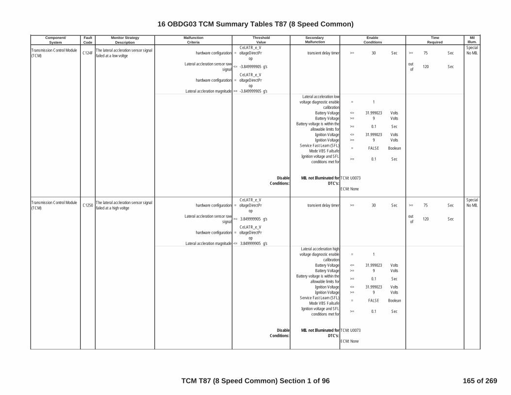
Component/ Fault Monitor Strategy Secondary MilSystem Code Description Malfunction Illum.
Transmission Control Module(TCM) C124F The lateral accleration sensor signal
failed at a low voltge hardware configuration =CeLATR_e_VoltageDirectPr
optransient delay timer >= 30 Sec >= 75 Sec
SpecialNo MIL
Lateral accleration sensor rawsignal <= -3.849999905 g's out
of 120 Sec
hardware configuration =CeLATR_e_VoltageDirectPr
opLateral accleration magnitude >= -3.849999905 g's
Lateral acceleration lowvoltage diagnostic enable
calibration= 1
Battery Voltage <= 31.999023 VoltsBattery Voltage >= 9 Volts
Battery voltage is within theallowable limits for >= 0.1 Sec
Ignition Voltage <= 31.999023 VoltsIgnition Voltage >= 9 Volts
Service Fast Learn (SFL)Mode VBS Failsafe = FALSE Boolean
Ignition voltage and SFLconditions met for >= 0.1 Sec
DisableConditions:
MIL not Illuminated forDTC's:
Transmission Control Module(TCM) C1250 The lateral accleration sensor signal
failed at a high voltge hardware configuration =CeLATR_e_VoltageDirectPr
optransient delay timer >= 30 Sec >= 75 Sec
SpecialNo MIL
Lateral accleration sensor rawsignal >= 3.849999905 g's out
of 120 Sec
hardware configuration =CeLATR_e_VoltageDirectPr
opLateral accleration magnitude <= 3.849999905 g's
Lateral acceleration highvoltage diagnostic enable
calibration= 1
Battery Voltage <= 31.999023 VoltsBattery Voltage >= 9 Volts
Battery voltage is within theallowable limits for >= 0.1 Sec
Ignition Voltage <= 31.999023 VoltsIgnition Voltage >= 9 Volts
Service Fast Learn (SFL)Mode VBS Failsafe = FALSE Boolean
Ignition voltage and SFLconditions met for >= 0.1 Sec
DisableConditions:
MIL not Illuminated forDTC's:
Malfunction Threshold Enable TimeCriteria Value Conditions Required
TCM: U0073
ECM: None
TCM: U0073
ECM: None
16 OBDG03 TCM Summary Tables T87 (8 Speed Common)
TCM T87 (8 Speed Common) Section 1 of 96 165 of 269

Component/ Fault Monitor Strategy Secondary MilSystem Code Description Malfunction Illum.
Malfunction Threshold Enable TimeCriteria Value Conditions Required
Transmission Control Module(TCM) C1251 The lateral accleration signal is stuck
at a high magnitude in range absolute value (lateral accleration) >= 0.529999971 g's absolute value (lateralaccleration) for stablity >= 0.53 g's >= 75 Sec Special
No MIL
absolute value (lateral accleration) <= 3.849999905 g's absolute value (lateralaccleration) for stablity <= 3.8499999 g's
stability time >= 30 SecDiagnostic shifting override
command = FALSE Boolean
Attained Gear State =1st
through8th
Attained Gear Slip <= 100 RPM
Transmission Type =
Clutch toClutch
Transmission
High Side Drivers enabled = TRUE BooleanVehicle Speed >= 15 kph
Lateral acceleration stuck inrange diagnostic enable
calibration= 1
Battery Voltage <= 31.999023 VoltsBattery Voltage >= 9 Volts
Battery voltage is within theallowable limits for >= 0.1 Sec
Ignition Voltage <= 31.999023 VoltsIgnition Voltage >= 9 Volts
Service Fast Learn (SFL)Mode VBS Failsafe = FALSE Boolean
Ignition voltage and SFLconditions met for >= 0.1 Sec
DisableConditions:
MIL not Illuminated forDTC's:
Transmission Control Module(TCM) C1252 The longitudinal accleration sensor
signal failed at a low voltge hardware configuration =CeLATR_e_VoltageDirectPr
optransient delay timer >= 30 Sec >= 75 Sec
SpecialNo MIL
longitudinal accleration sensor rawsignal <= -3.849999905 g's out
of 120 Sec
hardware configuration =CeLATR_e_VoltageDirectPr
oplongitudinal accleration sensor raw
signal >= -3.849999905 g's
longitudinal acceleration lowvoltage diagnostic enable
calibration= 1
Battery Voltage <= 31.999023 VoltsBattery Voltage >= 9 Volts
Battery voltage is within theallowable limits for >= 0.1 Sec
Ignition Voltage <= 31.999023 VoltsIgnition Voltage >= 9 Volts
TCM: P0716, P0717, P0721, P0722,P0723, P07BF, P07C0, P077B, P077C,P077D, P215C, U0073
ECM: None
16 OBDG03 TCM Summary Tables T87 (8 Speed Common)
TCM T87 (8 Speed Common) Section 2 of 96 166 of 269

Component/ Fault Monitor Strategy Secondary MilSystem Code Description Malfunction Illum.
Malfunction Threshold Enable TimeCriteria Value Conditions Required
Service Fast Learn (SFL)Mode VBS Failsafe = FALSE Boolean
Ignition voltage and SFLconditions met for >= 0.1 Sec
DisableConditions:
MIL not Illuminated forDTC's:
Transmission Control Module(TCM) C1253 The longitudinal accleration sensor
signal failed at a high voltge hardware configuration =CeLATR_e_VoltageDirectPr
optransient delay timer >= 30 Sec >= 75 Sec
SpecialNo MIL
longitudinal accleration sensor rawsignal >= 3.849999905 g's out
of 120 Sec
hardware configuration =CeLATR_e_VoltageDirectPr
oplongitudinal accleration sensor raw
signal <= 3.849999905 g's
longitudinal acceleration highvoltage diagnostic enable
calibration= 1
Battery Voltage <= 31.999023 VoltsBattery Voltage >= 9 Volts
Battery voltage is within theallowable limits for >= 0.1 Sec
Ignition Voltage <= 31.999023 VoltsIgnition Voltage >= 9 Volts
Service Fast Learn (SFL)Mode VBS Failsafe = FALSE Boolean
Ignition voltage and SFLconditions met for >= 0.1 Sec
DisableConditions:
MIL not Illuminated forDTC's:
Transmission Control Module(TCM) C1254 The longitudinal accleration signal is
stuck at a high magnitude in rangeabsolute value (longitudinal
accleration) >= 0.529999971 g's absolute value (longitudinalaccleration) for stablity >= 0.53 g's >= 75 Sec Special
No MILabsolute value (longitudinal
accleration) <= 3.849999905 g's absolute value (longitudinalaccleration) for stablity <= 3.8499999 g's out
of 120 Sec
stability time >= 30 SecDiagnostic shifting override
command = FALSE Boolean
Attained Gear State =1st
through8th
Attained Gear Slip <= 100 RPM
Transmission Type =
Clutch toClutch
Transmission
High Side Drivers enabled = TRUE Booleantransmssion output speed
acceleration >= 0.53 meter/second/second
TCM: U0073
ECM: None
TCM: U0073
ECM: None
16 OBDG03 TCM Summary Tables T87 (8 Speed Common)
TCM T87 (8 Speed Common) Section 3 of 96 167 of 269

Component/ Fault Monitor Strategy Secondary MilSystem Code Description Malfunction Illum.
Malfunction Threshold Enable TimeCriteria Value Conditions Required
Vehicle Speed >= 15 kphlongitudinal acceleration stuck
in range diagnostic enablecalibration
= 1
Battery Voltage <= 31.999023 VoltsBattery Voltage >= 9 Volts
Battery voltage is within theallowable limits for >= 0.1 Sec
Ignition Voltage <= 31.999023 VoltsIgnition Voltage >= 9 Volts
Service Fast Learn (SFL)Mode VBS Failsafe = FALSE Boolean
Ignition voltage and SFLconditions met for >= 0.1 Sec
DisableConditions:
MIL not Illuminated forDTC's:
Transmission Control Module(TCM) P0561
Battery to ignition voltageperformance error at the TCM for anextended period of time.
delta = ABS(TCM battery voltage -TCM ignition voltage) >= 3 Volts = 40 Fail counts
(100ms loop)
One Trip
Outof 50 Sample Counts
(100ms loop)battery to ignition voltage
performance diagnostic enablecalibration
= 1
TCM has battery voltagecircuit = 1 Boolean
Service mode $04 active andend of trip pocessing active = FALSE Boolean
Ignition Voltage Hyst Hi(enabled above this value) > 5 Volts
Ignition Voltage Hyst Lodisabled below this value) <= 2 Volts
DisableConditions:
MIL not Illuminated forDTC's:
Transmission Control Module(TCM) P0601 Transmission Electro-Hydraulic
Control Module Read Only MemoryIncorrect program/calibrations
checksum = TRUE Boolean >= 5
Fail Counts(background
taskcontinuous)
One Trip
NVM write error diagnoticenable = 1 Boolean
DisableConditions:
MIL not Illuminated forDTC's:
TCM: None
ECM: None
TCM: P0601
ECM: None
TCM: P0716, P0717, P0721, P0722,P0723, P07BF, P07C0, P077B, P077C,P077D, P215C, U0073
ECM: None
16 OBDG03 TCM Summary Tables T87 (8 Speed Common)
TCM T87 (8 Speed Common) Section 4 of 96 168 of 269

Component/ Fault Monitor Strategy Secondary MilSystem Code Description Malfunction Illum.
Malfunction Threshold Enable TimeCriteria Value Conditions Required
Transmission Control Module(TCM) P0603
Transmission Electro-HydraulicControl Module Long-Term MemoryReset
Non-volatile memory (static ordynamic) checksum failure at
controller initialization= TRUE Boolean Runs
Continously
One Trip
not programmed diagnoticenable = 1 Boolean
DisableConditions:
MIL not Illuminated forDTC's:
Transmission Control Module(TCM) P0604
Transmission Electro-HydraulicControl Module Random AccessMemory
secondary micro processor RAMerror = TRUE Boolean 1000 ms cont.
One Trip
OR
dual store RAM write time outerror = TRUE Boolean > 175
seconds(interrupt driven
based oncalling
functions)OR
system RAM fault = TRUE Boolean >= 3
counts(controller
initialization andbackground
taskcontinuous)
OR
cashe RAM fault = TRUE Boolean >= 3
counts(controller
initialization andbackground
taskcontinuous)
OR
secondary micro processor microcode error = TRUE Boolean >= 3
counts(controller
initialization andbackground
taskcontinuous)
ORService mode $04 active orend of trip processing active = FALSE Boolean
write attempt occurred duringRAM lock = TRUE Boolean > 65534
counts(background
taskcontinuous)
DisableConditions:
MIL not Illuminated forDTC's:
Internal TCM ProcessorIntegrity Fault P0606 Transmission Electro-Hydraulic
Control Module Processor Integritymain processor RAM circuit
hardware failure = TRUE Boolean RAM diagnotic test enable = 1 Boolean >= 5counts
(controllerinitialization)
One Trip
TCM: P0603
ECM: None
TCM: None
ECM: None
16 OBDG03 TCM Summary Tables T87 (8 Speed Common)
TCM T87 (8 Speed Common) Section 5 of 96 169 of 269

Component/ Fault Monitor Strategy Secondary MilSystem Code Description Malfunction Illum.
Malfunction Threshold Enable TimeCriteria Value Conditions Required
hardware reset source iscontroller power up reset = TRUE Boolean
OR
main processor flash EPROMcircuit hardware failure = TRUE Boolean flash EPROM diagnotic test
enable = 1 Boolean >= 5counts
(controllerinitialization)
hardware reset source iscontroller power up reset = TRUE Boolean
OR
main processor memory stackfailure = TRUE Boolean Service mode $04 active and
end of trip pocessing active = FALSE Boolean >= 5counts (100
mseccontinuous)
main processor memory stacktest enable = 1 Boolean
OR
secondary processor memorystack failure = TRUE Boolean secondary processor memory
stack test enable = 1 Boolean >= 5counts (12.5
mseccontinuous)
OR
secondary micro processorremedial action active on request = FALSE Boolean >= 1
counts(controller
power up, 12.5ms continuous)
OR
main processor ROM first testcomplete = FALSE Boolean >= 35
counts (12.5msec
continuous)OR
secondary processor to mainprocessor seed sequence fault = TRUE Boolean >= 0.5 seconds
OR
seed sequence error FALSE Boolean program sequence watchcommunication fault = FALSE Boolean >= 3
counts (12.5msec
continuous)main processor to secondary
processor serial peripheralinterface error
= FALSE Boolean >= 17counts (12.5
mseccontinuous)
seed sequence test enable =
see table50 in
supportingdocuments
Boolean
battery voltage > 11 Voltsignition voltage >= 11 volts
OR
seed key fault current loop = TRUE Boolean seed key test enable =
see table50 in
supportingdocuments
Boolean
seed key fault previous loop = TRUE BooleanService mode $04 active and
end of trip processing active = FALSE Boolean
OR
16 OBDG03 TCM Summary Tables T87 (8 Speed Common)
TCM T87 (8 Speed Common) Section 6 of 96 170 of 269

Component/ Fault Monitor Strategy Secondary MilSystem Code Description Malfunction Illum.
Malfunction Threshold Enable TimeCriteria Value Conditions Required
normalize 0-5 volt (absolute value(analog to digital test voltage
commanded - actual analog todigital voltage feedback))
> 3.298950195 percent analog to digital voltage testenabled = 1 Boolean >= 3
counts (50msec
continuous)
ignition voltage >= 7 Volts >= 8counts (50
mseccontinuous)
analog to digital voltagechannel enabled =
see Table46 in
supportingdocuments
Boolean
analog to digital test voltagecommand =
see Table47 in
supportingdocuments
Volts >= 0.2 seconds
Service mode $04 active andend of trip processing active = FALSE Boolean
OR
arithmatic logic unit 1 test pass = FALSE Boolean arithmatic logic unit test enable = 1 Boolean
at controllerinitialization,then 12.5 ms
cont.arithmatic logic unit 1 test pass
previous loop = FALSE Boolean
Service mode $04 active andend of trip processing active = FALSE Boolean
A and B and C must occurA: starter motor engaged = TRUE Boolean
B: ignition voltage <= 11 Volts
C: starter motor engaged time < 0.025 sec
A and B must occurA: ignition voltage <= 6.4091797 Volts
B: ignition low voltage time >= 2.50E-02 sec
arithmatic logic unit 2 test pass = FALSE Boolean arithmatic logic unit test enable = 1 Boolean
at controllerinitialization,then 12.5 ms
cont.arithmatic logic unit 1 test pass
previous loop = FALSE Boolean
Service mode $04 active andend of trip processing active = FALSE Boolean
A and B and C must occurA: starter motor engaged = TRUE Boolean
B: ignition voltage <= 11 Volts
C: starter motor engaged time < 0.025 sec
ORsecondary processor arithmatic
logic unit fault = TRUE Boolean
OR
clock test fail current loop = TRUE Boolean clock test enable = 1 Boolean
at controllerinitialization,then 12.5 ms
cont.
16 OBDG03 TCM Summary Tables T87 (8 Speed Common)
TCM T87 (8 Speed Common) Section 7 of 96 171 of 269

Component/ Fault Monitor Strategy Secondary MilSystem Code Description Malfunction Illum.
Malfunction Threshold Enable TimeCriteria Value Conditions Required
clock test fail previous loop = TRUE BooleanService mode $04 active and
end of trip processing active = FALSE Boolean
A and B and C must occurA: starter motor engaged = TRUE Boolean
B: ignition voltage <= 11 Volts
C: starter motor engaged time < 0.025 sec
A and B must occurA: ignition voltage <= 6.4091797 Volts
B: ignition low voltage time >= 2.50E-02 secOR
configuration register test failcurrent loop = TRUE Boolean configuration register test
enable = 1 Boolean
at controllerinitialization,then 12.5 ms
cont.configuration register test fail
previous loop = TRUE Boolean
Service mode $04 active andend of trip processing active = FALSE Boolean
A and B and C must occurA: starter motor engaged = TRUE Boolean
B: ignition voltage <= 11 Volts
C: starter motor engaged time < 0.025 sec
A and B must occurA: ignition voltage <= 6.4091797 Volts
B: ignition low voltage time >= 2.50E-02 secOR
secondary processor configurationregister fault = TRUE Boolean
ORA or B occur
A: direct memeory access (DMA)read/write test result FALSE Boolean flash data transfer test enable = 1 Boolean
normalcontroller
initialization
B: direct memeory access (DMA)read/write value $5AA5A55A hexadecimal
value flash data transfer test enable = 1 Booleannormal
controllerinitialization
software uses DMA peripheralfunction to write and read
$5AA5A55A to flash memorylocations to verify each flash
memory location
running reset = FALSE Boolean
normal power up reset = TRUE BooleanOR
secondary micro processordetects main micor processor SPI
fault= TRUE Boolean
OR
A or B or C or D occur seed and key store fault testenable = 0 Boolean
A: last 6.25 msec seed and keytime >
see Table 48in supportingdocuments
sec
16 OBDG03 TCM Summary Tables T87 (8 Speed Common)
TCM T87 (8 Speed Common) Section 8 of 96 172 of 269

Component/ Fault Monitor Strategy Secondary MilSystem Code Description Malfunction Illum.
Malfunction Threshold Enable TimeCriteria Value Conditions Required
B: last 12.5 msec seed and keytime >
see Table 48in supportingdocuments
sec
C: last 50 msec seed and key time >see Table 48in supportingdocuments
sec
D: last lores engine interrupt seedand key time >
see Table 48in supportingdocuments
sec
OR
A or B or C or D occur prgram sequence watch testenable =
see3D_Table
1 insupportingdocuments
Boolean
A: 6.25 msec program sequencefault fail count >=
see Table 49in supportingdocuments
counts (50 mseccontinuous on6.25 msec timeinterrupt)
B: 12.5 msec program sequencefault fail count >=
see Table 49in supportingdocuments
counts (50 mseccontinuous on12.5 msec timeinterrupt)
C: 50 msec program sequencefault fail count >=
see Table 49in supportingdocuments
counts (50 mseccontinuous)
D: engine lores interrupt programsequence fault fail count >=
see Table 49in supportingdocuments
counts (onexecution ofengine loresinterrupts ECMonly)
ORsecondary processor reports SPI
communication fault = TRUE Boolean Service mode $04 active andend of trip processing active = FALSE Boolean
secondary processor reportsSPI communication fault
previous loop= TRUE Boolean
ORSPI valid messsage received by
main micro processor = FALSE Boolean
= previous SPImessage type
A and B and C must occurA: starter motor engaged = TRUE Boolean
B: ignition voltage <= 11 Volts
C: starter motor engaged time < 0.025 sec
SPI message checksum fault FASLE Boolean
16 OBDG03 TCM Summary Tables T87 (8 Speed Common)
TCM T87 (8 Speed Common) Section 9 of 96 173 of 269
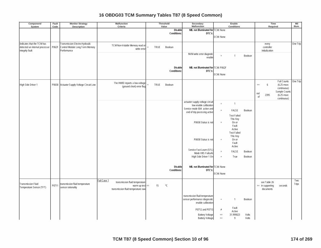
Component/ Fault Monitor Strategy Secondary MilSystem Code Description Malfunction Illum.
Malfunction Threshold Enable TimeCriteria Value Conditions Required
DisableConditions:
MIL not Illuminated forDTC's:
Indicates that the TCM hasdetected an internal processorintegrity fault
P062FTransmission Electro-HydraulicControl Module Long Term MemoryPerformance
TCM Non-Volatile Memory read orwrite error = TRUE Boolean
everycontroller
initialization
One Trip
NVM write error diagnoticenable = 1 Boolean
DisableConditions:
MIL not Illuminated forDTC's:
High Side Driver 1 P0658 Actuator Supply Voltage Circuit Low The HWIO reports a low voltage(ground short) error flag = TRUE Boolean >= 6
Fail Counts(6.25 mseccontinuous)
One Trip
outof 2395
Sample Counts(6.25 mseccontinuous)
actuator supply voltage circuitlow enable calibration = 1
Service mode $04 active andend of trip pocessing active = FALSE Boolean
P0658 Status is not =
Test FailedThis Key
On orFaultActive
P0658 Status is not =
Test FailedThis Key
On orFaultActive
Service Fast Learn (SFL)Mode VBS Failsafe = FALSE Boolean
High Side Driver 1 On = True Boolean
DisableConditions:
MIL not Illuminated forDTC's:
Transmission FluidTemperature Sensor (TFT) P0711 transmission fluid temperature
sensor rationality
Fail Case 1 transmission fluid temperaturewarm up test
transmission fluid temperature raw<= 15 ºC >=
see Table 26in supportingdocuments
seconds
TwoTrips
transmission fluid temperaturesensor performance diagnsotic
enable calibration= 1 Boolean
P0712 and P0713 FaultActive
Battery Voltage <= 31.999023 VoltsBattery Voltage >= 9 Volts
TCM: None
ECM: None
TCM: P062F
ECM: None
TCM: None
ECM: None
16 OBDG03 TCM Summary Tables T87 (8 Speed Common)
TCM T87 (8 Speed Common) Section 10 of 96 174 of 269
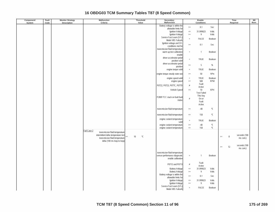
Component/ Fault Monitor Strategy Secondary MilSystem Code Description Malfunction Illum.
Malfunction Threshold Enable TimeCriteria Value Conditions Required
Battery voltage is within theallowable limits for >= 0.1 Sec
Ignition Voltage <= 31.999023 VoltsIgnition Voltage >= 9 Volts
Service Fast Learn (SFL)Mode VBS Failsafe = FALSE Boolean
Ignition voltage and SFLconditions met for >= 0.1 Sec
transmission fluid temperaturewarm up test calibration
enable= 1 Boolean
driver accelerator pedalposition valid = TRUE Boolean
driver accelerator pedalposition >= 5 %
engine torque valid = TRUE Boolean
engine torque steady state raw >= 50 N*m
engine speed valid = TRUE Booleanengine speed >= 500 RPM
P0722, P0723, P077C, P077D FaultActive
Vehicle Speed >= 10 KPH
P2809 TCC stuck on fault faultstatus
Test FailedThis Key
On orFaultActive
transmission fluid temperature >= -40 ºC
transmission fluid temperature <= 150 ºC
engine coolant temperaturevalid = TRUE Boolean
engine coolant temperature >= -40 ºCengine coolant temperature <= 150 ºC
Fail Case 2 transmission fluid temperatureintermittent delta temperature test
transmission fluid temperaturedelta (100 ms loop to loop)
>= 10 ºC >= 8 seconds (100ms cont.)
>= 12 seconds (100ms cont.)
transmission fluid temperaturesensor performance diagnsotic
enable calibration= 1 Boolean
P0712 and P0713 FaultActive
Battery Voltage <= 31.999023 VoltsBattery Voltage >= 9 Volts
Battery voltage is within theallowable limits for >= 0.1 Sec
Ignition Voltage <= 31.999023 VoltsIgnition Voltage >= 9 Volts
Service Fast Learn (SFL)Mode VBS Failsafe = FALSE Boolean
16 OBDG03 TCM Summary Tables T87 (8 Speed Common)
TCM T87 (8 Speed Common) Section 11 of 96 175 of 269
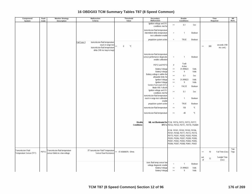
Component/ Fault Monitor Strategy Secondary MilSystem Code Description Malfunction Illum.
Malfunction Threshold Enable TimeCriteria Value Conditions Required
Ignition voltage and SFLconditions met for >= 0.1 Sec
transmission fluid temperatureintermittent delta temperature
test calibration enable= 1 Boolean
propulsion system active = TRUE BooleanFail Case 3 transmission fluid temperature
stuck in range testtransmission fluid temperature
delta (100 ms loop to loop)
<= 0 ºC >= 300 seconds (100ms cont.)
transmission fluid temperaturesensor performance diagnsotic
enable calibration= 1 Boolean
P0712 and P0713 FaultActive
Battery Voltage <= 31.999023 VoltsBattery Voltage >= 9 Volts
Battery voltage is within theallowable limits for >= 0.1 Sec
Ignition Voltage <= 31.999023 VoltsIgnition Voltage >= 9 Volts
Service Fast Learn (SFL)Mode VBS Failsafe = FALSE Boolean
Ignition voltage and SFLconditions met for >= 0.1 Sec
transmission fluid temperaturestuck in range test calibration
enable= 1 Boolean
propulsion system active = TRUE Boolean
transmission fluid temperature <= 150 ºC
transmission fluid temperature >= -40 ºC
DisableConditions:
MIL not Illuminated forDTC's:
Transmission FluidTemperature Sensor (TFT) P0712 Transmission fluid temperature
sensor failed at a low voltageIf Transmission Fluid Temperature
Sensor Raw Resistance <= 47.45000076 Ohms >= 10 Fail Time (Sec)TwoTrips
outof 12 Sample Time
(Sec)trans fluid temp sensor low
voltage diagnostic enable = 1 Boolean
Battery Voltage <= 31.999023 VoltsBattery Voltage >= 9 Volts
TCM: P0716, P0712, P0713, P0717,P0722, P0723, P077C, P077D, P02809
ECM: P0101, P0102, P0103, P0106,P0107, P0108, P0171, P0172, P0174,P0175, P0201, P0202, P0203, P0204,P0205, P0206, P0207, P0208, P0300,P0301, P0302, P0303, P0304, P0305,P0306, P0307, P0308, P0401, P042E
16 OBDG03 TCM Summary Tables T87 (8 Speed Common)
TCM T87 (8 Speed Common) Section 12 of 96 176 of 269

Component/ Fault Monitor Strategy Secondary MilSystem Code Description Malfunction Illum.
Malfunction Threshold Enable TimeCriteria Value Conditions Required
Battery voltage is within theallowable limits for >= 0.1 Sec
Ignition Voltage <= 31.999023 VoltsIgnition Voltage >= 9 Volts
Service Fast Learn (SFL)Mode VBS Failsafe = FALSE Boolean
Ignition voltage and SFLconditions met for >= 0.1 Sec
DisableConditions:
MIL not Illuminated forDTC's:
Transmission FluidTemperature Sensor (TFT) P0713 Transmission fluid temperature
sensor failed at a high voltageIf Transmission Fluid Temperature
Sensor Raw Resistance >= 105445 Ohms >= 10 Fail Time (Sec)TwoTrips
outof 12 Sample Time
(Sec)trans fluid temp sensor high
voltage diagnostic enable = 1 Boolean
Battery Voltage <= 31.999023 VoltsBattery Voltage >= 9 Volts
Battery voltage is within theallowable limits for >= 0.1 Sec
Ignition Voltage <= 31.999023 VoltsIgnition Voltage >= 9 Volts
Service Fast Learn (SFL)Mode VBS Failsafe = FALSE Boolean
Ignition voltage and SFLconditions met for >= 0.1 Sec
DisableConditions:
MIL not Illuminated forDTC's:
Transmission Input SpeedSensor (TISS) P0716 Input Speed Sensor Performance
Abolute Value Of TransmissionInput Speed Sensor Delta (loop to
loop)>= 850 RPM
One Trip
>= 1.5 seconds>= 5 fail events
speed sensor processing = time based
Service mode $04 active andend of trip pocessing active = FALSE Boolean
transmission input speedsensor performance diagnostic
enable= 1 Boolean
Ignition Voltage Hyst Hi(enabled above this value) > 5 Volts
Ignition Voltage Hyst Lodisabled below this value) <= 2 Volts
Service Fast Learn (SFL)Mode VBS Failsafe = FALSE Boolean
Ignition Voltage Max (disabledabove this value) <= 31.999023 Volts
TCM: None
ECM: None
TCM: None
ECM: None
16 OBDG03 TCM Summary Tables T87 (8 Speed Common)
TCM T87 (8 Speed Common) Section 13 of 96 177 of 269

Component/ Fault Monitor Strategy Secondary MilSystem Code Description Malfunction Illum.
Malfunction Threshold Enable TimeCriteria Value Conditions Required
Ignition Voltage Min (enabledabove this value) >= 9 Volts
P0717 Status is not =Test FailedThis Key
On
P07BF Status is not =Test FailedThis Key
On
P07C0 Status is not =Test FailedThis Key
Onlast valid transmission input
speed > 148 RPM
ORtransmission input speed raw >= 148 RPMtransmssion input speed last
valid or raw timer >= 2 Seconds
transmission input speedsensor performance test
complete (initialized to FALSEset to TRUE when P0716 fails)
= FALSE Boolean
transmission hydraulic systempressurized = TRUE Boolean
driver accelerator pedalposition available = TRUE Boolean
engine torque inaccurate = FALSE BooleanTransmission Output Speed
Sensor Raw Speed >= 230 RPM
driver accelerator pedalposition >= 5.0003052 Pct
engine actual torque steadystate raw <= 8191.875 N*m
engine actual torque steadystate raw >= 30 N*m
P0716 Status is not =
Test FailedThis Key
On orFaultActive
DisableConditions:
MIL not Illuminated forDTC's:
Transmission Input SpeedSensor (TISS) P0717 Input Speed Sensor Circuit Low
VoltageFail Case 1 Transmission Input Speed is < 100 RPM >= 4 Fail Time (Sec) One Trip
ORFail Case 2 P0722 DTC Status is Test Failed
This Key On and and controlleruses single power feed
Transmission Input Speed is
< 175 RPM
Controller uses a single powersupply for the speed sensors = 0 Boolean
TCM: P0716, P0717, P07BF, P07C0
ECM: P0101, P0102, P0103, P0121,P0122, P0123
16 OBDG03 TCM Summary Tables T87 (8 Speed Common)
TCM T87 (8 Speed Common) Section 14 of 96 178 of 269

Component/ Fault Monitor Strategy Secondary MilSystem Code Description Malfunction Illum.
Malfunction Threshold Enable TimeCriteria Value Conditions Required
speed sensor processing = time based
Service mode $04 active andend of trip pocessing active = FALSE Boolean
transmission input speedsensor low diagnostic enable = 1 Boolean
transmission hydraulic systempressurized = TRUE Boolean
Ignition Voltage Hyst Hi(enabled above this value) > 5 Volts
Ignition Voltage Hyst Lodisabled below this value) <= 2 Volts
speed sensor connected tocontroller = 1 Boolean
P0722 Status is not = fault active
P0723 Status is not = fault active
P077C Status is not = fault active
P077D Status is not = fault active
brake pedal position is not >= 69.999695 Pctengine torque inaccurate = FALSE Boolean
P0716 Status is not =Test FailedThis Key
On
P07BF Status is not =Test FailedThis Key
On
P07C0 Status is not =Test FailedThis Key
Ondriver accelerator pedal
position >= 5 Pct
engine actual torque steadystate raw <= 8191.875 N*m
engine actual torque steadystate raw >= 30 N*m
attained gear low <CeCGSR_e_CR_Sixt
hTransmission Output Speed
Sensor Raw Speed whenattained gear low
>= 72 RPM
attained gear high >=CeCGSR_e_CR_Sixt
hTransmission Output Speed
Sensor Raw Speed whenattained gear high
>= 230 RPM
P0717 Status is not =
Test FailedThis Key
On orFaultActive
16 OBDG03 TCM Summary Tables T87 (8 Speed Common)
TCM T87 (8 Speed Common) Section 15 of 96 179 of 269
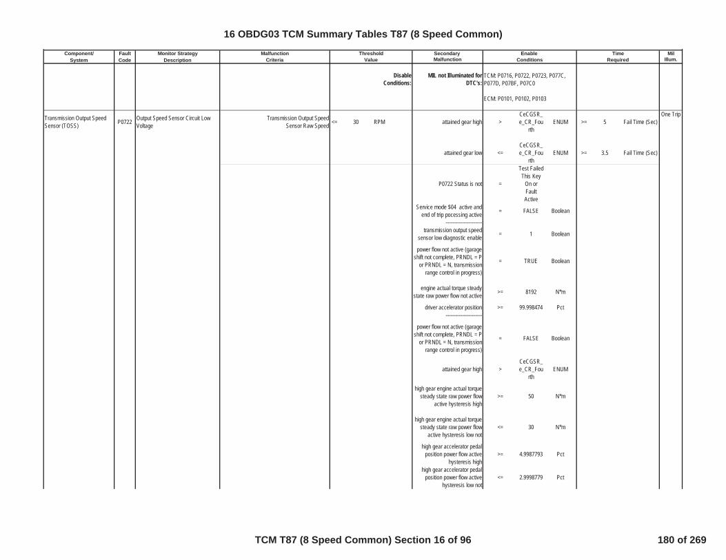
Component/ Fault Monitor Strategy Secondary MilSystem Code Description Malfunction Illum.
Malfunction Threshold Enable TimeCriteria Value Conditions Required
DisableConditions:
MIL not Illuminated forDTC's:
Transmission Output SpeedSensor (TOSS) P0722 Output Speed Sensor Circuit Low
VoltageTransmission Output Speed
Sensor Raw Speed <= 30 RPM attained gear high >CeCGSR_e_CR_Fou
rthENUM >= 5 Fail Time (Sec)
One Trip
attained gear low <=CeCGSR_e_CR_Fou
rthENUM >= 3.5 Fail Time (Sec)
P0722 Status is not =
Test FailedThis Key
On orFaultActive
Service mode $04 active andend of trip pocessing active = FALSE Boolean
----------------------transmission output speed
sensor low diagnostic enable = 1 Boolean
power flow not active (garageshift not complete, PRNDL = P
or PRNDL = N, transmissionrange control in progress)
= TRUE Boolean
engine actual torque steadystate raw power flow not active >= 8192 N*m
driver accelerator position >= 99.998474 Pct----------------------
power flow not active (garageshift not complete, PRNDL = P
or PRNDL = N, transmissionrange control in progress)
= FALSE Boolean
attained gear high >CeCGSR_e_CR_Fou
rthENUM
high gear engine actual torquesteady state raw power flow
active hysteresis high>= 50 N*m
high gear engine actual torquesteady state raw power flow
active hysteresis low not<= 30 N*m
high gear accelerator pedalposition power flow active
hysteresis high>= 4.9987793 Pct
high gear accelerator pedalposition power flow active
hysteresis low not<= 2.9998779 Pct
TCM: P0716, P0722, P0723, P077C,P077D, P07BF, P07C0
ECM: P0101, P0102, P0103
16 OBDG03 TCM Summary Tables T87 (8 Speed Common)
TCM T87 (8 Speed Common) Section 16 of 96 180 of 269

Component/ Fault Monitor Strategy Secondary MilSystem Code Description Malfunction Illum.
Malfunction Threshold Enable TimeCriteria Value Conditions Required
attained gear low <=CeCGSR_e_CR_Fou
rthENUM
low gear engine actual torquesteady state raw power flow
active hysteresis high>= 80 N*m
low gear engine actual torquesteady state raw power flow
active hysteresis low not<= 50 N*m
low gear accelerator pedalposition power flow active
hysteresis high>= 7.9986572 Pct
low gear accelerator pedalposition power flow active
hysteresis low not<= 4.9987793 Pct
----------------------use transmission input speed
sensor = TRUE Boolean
speed sensors have singlepower feed = 0 Boolean
transmission input speedsensor signal raw <= 8191.875 RPM
transmission input speedsensor signal raw >= 175 RPM
----------------------use transmission input speed
sensor = FALSE Boolean
speed sensors have singlepower feed = 0 Boolean
engine speed sensor signal <= 8191.875 RPMengine speed sensor signal >= 3500 RPM
----------------------
P0716 Status is not = FaultActive
P0717 Status is not = FaultActive
P07BF Status is not = FaultActive
P07C0 Status is not = FaultActive
PTO disable = 1 BooleanPTO engaged = FALSE Boolean
driver accelerator pedalposition available = TRUE Boolean
engine torque inaccurate = FALSE Booleantransmission hydraulic system
pressurized = TRUE Boolean
Ignition Voltage Hyst Hi(enabled above this value) > 5 Volts
Ignition Voltage Hyst Lodisabled below this value) <= 2 Volts
Service Fast Learn (SFL)Mode VBS Failsafe = FALSE Boolean
Ignition Voltage Max (disabledabove this value) <= 31.999023 Volts
Ignition Voltage Min (enabledabove this value) >= 9 Volts
16 OBDG03 TCM Summary Tables T87 (8 Speed Common)
TCM T87 (8 Speed Common) Section 17 of 96 181 of 269

Component/ Fault Monitor Strategy Secondary MilSystem Code Description Malfunction Illum.
Malfunction Threshold Enable TimeCriteria Value Conditions Required
transmssion fluid temperaturesensor >= -40 ºC
P0723 Status is not =Test FailedThis Key
On
P077C Status is not =Test FailedThis Key
On
P077D Status is not =Test FailedThis Key
On
DisableConditions:
MIL not Illuminated forDTC's:
Transmission Output SpeedSensor (TOSS) P0723 Output Speed Sensor Circuit
Intermittent transmission output speed delta >=see "set fail
RPMthreshold"
RPM >= 1.5 Fail Time (Sec)One Trip
>= 5 fail eventstransmission output speed >= 36 RPM
OR
transmission output speed lastvalid output speed before drop >= 36 RPM
for TOSS output speed raw,TOSS last valid output speed,
time>= 2 seconds
set fail RPM threshold4WD low state valid = TRUE Boolean
4WD low state = TRUE Boolean2WD delta transmission output
speed fail threshold = 500 RPM
4WD gear ratio = 2.71final delta transmission output
speed fail threshold = 1355 RPM
OR4WD low state valid = TRUE Boolean
4WD low state = FALSE BooleanOR
4WD low state valid = FALSE Boolean2WD delta transmission output
speed fail threshold = 500 RPM
final delta transmission outputspeed fail threshold = 500 RPM
----------------------Range_Disable = FALSE See Below
OR----------------------
Neutral_Range_Enable = TRUE See BelowAnd
Neutral_Speed_Enable = TRUE See Beloware TRUE concurrently
----------------------
TCM: P0716, P0717, P0723
ECM: P0101, P0102, P0103, P0121,P0122, P0123
16 OBDG03 TCM Summary Tables T87 (8 Speed Common)
TCM T87 (8 Speed Common) Section 18 of 96 182 of 269

Component/ Fault Monitor Strategy Secondary MilSystem Code Description Malfunction Illum.
Malfunction Threshold Enable TimeCriteria Value Conditions Required
Transmission_Range_Enable = TRUE See BelowTransmission_Input_Speed_E
nable = TRUE See Below
transmission output speedsensor performance diagnostic
enable= 1 Boolean
Service mode $04 active andend of trip pocessing active = FALSE Boolean
No Change in Transfer CaseRange (High <-> Low) for >= 5 Seconds
P0723 Status is not =
Test FailedThis Key
On orFaultActive
Disable this DTC if the PTO isactive = 1 Boolean
Ignition Voltage Hyst Hi(enabled above this value) > 5 Volts
Ignition Voltage Hyst Lodisabled below this value) <= 2 Volts
Service Fast Learn (SFL)Mode VBS Failsafe = FALSE Boolean
Ignition Voltage Max (disabledabove this value) <= 31.999023 Volts
Ignition Voltage Min (enabledabove this value) >= 9 Volts
P077C Status is not =Test FailedThis Key
On
P077D Status is not =Test FailedThis Key
OnEnable_Flags Defined Below
Transmission_Input_Speed_Enable is TRUE when either TISCondition 1 or TIS Condition 2
is TRUE:
TIS Condition 1 is TRUE whenboth of the following conditions
are satsified for>= 2 Enable Time
(Sec)
Input Speed Delta <= 4095.875 RPMRaw Input Speed >= 148 RPM
TIS Condition 2 is TRUE whenALL of the next two conditions
are satisfiedInput Speed = 0 RPM
A Single Power Supply is usedfor all speed sensors = TRUE Boolean
----------------------Neutral_Range_Enable is
TRUE when any of the next 3conditions are TRUE
Transmission Range is = Neutral ENUM
16 OBDG03 TCM Summary Tables T87 (8 Speed Common)
TCM T87 (8 Speed Common) Section 19 of 96 183 of 269

Component/ Fault Monitor Strategy Secondary MilSystem Code Description Malfunction Illum.
Malfunction Threshold Enable TimeCriteria Value Conditions Required
Transmission Range is =Reverse/N
eutralTransitonal
ENUM
Transmission Range is =
Neutral/Drive
Transitional
ENUM
KeTOSI_n_OutSpdInNeutNoiseMaxLim < 50 RPM
and when Loop to Loop Dropof Transmission Output Speed
is> 500 RPM
----------------------Range_Disable is TRUE when
any of the next threeconditions are TRUE
Transmission Range is = Park ENUM
Transmission Range is =Park/Reve
rseTransitonal
ENUM
Input Clutch is not = ON (FullyApplied) ENUM
----------------------Neutral_Speed_Enable is
TRUE when All of the nextthree conditions are satsified
for
> 2 Seconds
Transmission Output Speed >= 50 RPM
The loop to loop change of theTransmission Output Speed is < 20 RPM
The loop to loop change of theTransmission Output Speed is > -140 RPM
----------------------Transmission_Range_Enableis TRUE when one of the next
six conditions is TRUETransmission Range is = Neutral ENUM
Transmission Range is =
Reverse/Neutral
Transitional
ENUM
Transmission Range is =
Neutral/Drive
Transitional
ENUM
Time since a driven range(R,D) has been selected >=
see Table21 in
supportingdocuments
Sec
Transmission Output SpeedSensor Raw Speed >= 250 RPM
16 OBDG03 TCM Summary Tables T87 (8 Speed Common)
TCM T87 (8 Speed Common) Section 20 of 96 184 of 269
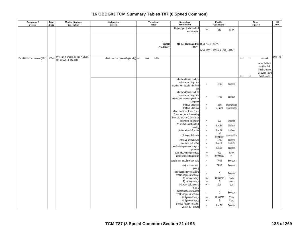
Component/ Fault Monitor Strategy Secondary MilSystem Code Description Malfunction Illum.
Malfunction Threshold Enable TimeCriteria Value Conditions Required
Output Speed when a faultwas detected >= 250 RPM
DisableConditions:
MIL not Illuminated forDTC's:
Variable Force Solenoid (VFS) P0746 Pressure Control Solenoid A StuckOff (clutch1/CB1278R) absolute value (attained gear slip) >= 400 RPM >= 3 seconds One Trip
when fail timereaches fail
limit incrementfail event count
>= 3 event countsclutch solenoid stuck onperformance diagnostic
monitor test deceleration limitnot
= TRUE boolean
clutch solenoid stuck onperformance diagnostic
monitor test return to previousrange not
= TRUE boolean
PRNDL State not = park enumerationPRNDL State not = neutral enumeration
while conditinos A and B andC are met, time down delay
from clibration to 0.0 secondsdelay time calibration = 0.5 seconds
A) neutral condition faultpending = FALSE boolean
B) intrusive shift active = FALSE boolean
C) range shift state = shiftcomplete enumeration
intrusive shift allowed = TRUE booleanintrusive shift active = FALSE boolean
steady state pressure adapt inprogress = FALSE boolean
transmission output speed >= 100 RPMaccelerator pedal position >= 0.5004883 %
accelerator pedal position valid = TRUE Boolean
engine speed valid = TRUE BooleanD or E
D) select battery voltage toenable diagnsotic monitor = 0 Boolean
E) battery voltage <= 31.999023 voltsE) battery voltage >= 9 volts
E) battery voltage time >= 0.1 secF or G
F) select ignition voltage toenable diagnsotic monitor = 0 Boolean
G) Ignition Voltage <= 31.999023 VoltsG) Ignition Voltage >= 9 Volts
Service Fast Learn (SFL)Mode VBS Failsafe = FALSE Boolean
TCM: P077C, P077D
ECM: P2771, P279A, P279B, P279C
16 OBDG03 TCM Summary Tables T87 (8 Speed Common)
TCM T87 (8 Speed Common) Section 21 of 96 185 of 269

Component/ Fault Monitor Strategy Secondary MilSystem Code Description Malfunction Illum.
Malfunction Threshold Enable TimeCriteria Value Conditions Required
Ignition voltage and SFLconditions met for >= 0.1 Sec
Hydraulic System Pressurized = TRUE Booleanhigh side driver 1 enabled = TRUE Booleanhigh side driver 2 enabled = TRUE Boolean
DisableConditions:
MIL not Illuminated forDTC's:
Variable Force Solenoid (VFS) P0747 Pressure Control Solenoid A StuckOn (clutch1/CB1278R)
automatic transmission shifttorque phase test (A) or inertiaphase test (B) fail event count
deceleration limited
>=see Table 32in supportingdocuments
fail event counts
One Trip
automatic transmission shifttorque phase test (A) or inertia
phase test (B) fail event count nodeceleration
>=see Table 33in supportingdocuments
fail event counts
A) absolute value (attained gearslip), fail during post torque phase
of transmission automatic shift,before engine speed change, pull
up or pull down occurs
<= 40 RPM
increment fail time when slipcriteria met, fail time for power
down shift>=
see Table 29in supportingdocuments
seconds
increment fail time when slipcriteria met, fail time for up shift or
closed throttle down shiftdeceleration limited
>=see Table 30in supportingdocuments
seconds
increment fail time when slipcriteria met, fail time for up shift or
closed throttle down shift nodeceleration
>=see Table 31in supportingdocuments
seconds
when fail timereaches fail
limit incrementfail event count
aboveB) absolute value (command gear
slip), fail during inertia phase oftransmission automatic shift,
engine speed change begins, pullup or pull down
>= 70 RPM
TCM: P0716, P0717, P0722, P0723,P077C, P077D, P07BF, P07C0, P1824,P182A, P182B, P182C, P182D, P182E,P182F, P1838, P1839, P1840, P1841,P18B5, P18B6, P18B7, P18B8, P18B9,P18BA, P18BB, P18BC, P18BD, P18BE,P18BF, P18C0, P18C1, P18C2, P18C3,P1915, P2534
ECM: P0101, P0102, P0103, P0106,P0107, P0108, P0171, P0172, P0174,P0175, P0201, P0202, P0203, P0204,P0205, P0206, P0207, P0208, P0300,P0301, P0302, P0303, P0304, P0305,P0306, P0307, P0308, P0401, P042E
16 OBDG03 TCM Summary Tables T87 (8 Speed Common)
TCM T87 (8 Speed Common) Section 22 of 96 186 of 269

Component/ Fault Monitor Strategy Secondary MilSystem Code Description Malfunction Illum.
Malfunction Threshold Enable TimeCriteria Value Conditions Requiredincrement fail time when slip
criteria met, fail time during shiftdeceleration limited
>=see Table 35in supportingdocuments
seconds
increment fail time when slipcriteria met, fail time during shift
no deceleration>=
see Table 36in supportingdocuments
seconds
when fail timereaches fail
limit incrementfail event count
aboveinertia phase test measured
gear ratio >= 0.558
inertia phase test measuredgear ratio <= 4.7150002
inertia phase test measuredgear ratio time >= 0.15 seconds
clutch test enabled =
see Table10 in
supportingdocuments
boolean
post torque phase test enginetorque hysteresis high enablefor upshift or power on down
shift
>=
see Table11 in
supportingdocuments
N*m
post torque phase test enginetorque hysteresis low disablefor upshift or power on down
shift
>
see Table12 in
supportingdocuments
N*m
post torque phase test enginetorque hysteresis high enablefor closed throttle down shift
>=
see Table13 in
supportingdocuments
N*m
post torque phase test enginetorque hysteresis low disablefor closed throttle down shift
>
see Table14 in
supportingdocuments
N*m
inertia phase test enginetorque hysteresis high enablefor upshift or power on down
shift
>=
see Table15 in
supportingdocuments
N*m
inertia phase test enginetorque hysteresis low disablefor upshift or power on down
shift
>
see Table16 in
supportingdocuments
N*m
inertia phase test enginetorque hysteresis high enablefor closed throttle down shift
>=
see Table17 in
supportingdocuments
N*m
16 OBDG03 TCM Summary Tables T87 (8 Speed Common)
TCM T87 (8 Speed Common) Section 23 of 96 187 of 269
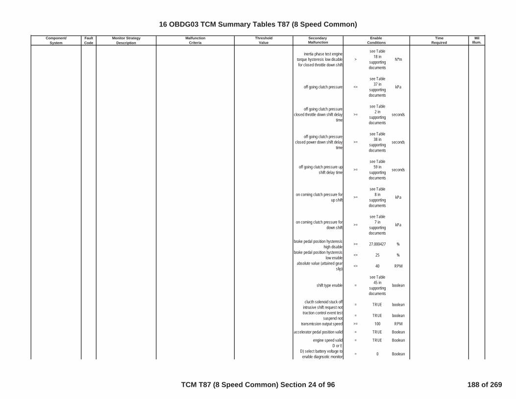
Component/ Fault Monitor Strategy Secondary MilSystem Code Description Malfunction Illum.
Malfunction Threshold Enable TimeCriteria Value Conditions Required
inertia phase test enginetorque hysteresis low disablefor closed throttle down shift
>
see Table18 in
supportingdocuments
N*m
off going clutch pressure <=
see Table37 in
supportingdocuments
kPa
off going clutch pressureclosed throttle down shift delay
time>=
see Table2 in
supportingdocuments
seconds
off going clutch pressureclosed power down shift delay
time>=
see Table38 in
supportingdocuments
seconds
off going clutch pressure upshift delay time >=
see Table59 in
supportingdocuments
seconds
on coming clutch pressure forup shift >=
see Table8 in
supportingdocuments
kPa
on coming clutch pressure fordown shift >=
see Table7 in
supportingdocuments
kPa
brake pedal position hysteresishigh disable >= 27.000427 %
brake pedal position hysteresislow enable <= 25 %
absolute value (attained gearslip) <= 40 RPM
shift type enable =
see Table45 in
supportingdocuments
boolean
clucth solenoid stuck offintrusive shift request not = TRUE boolean
traction control event testsuspend not = TRUE boolean
transmission output speed >= 100 RPM
accelerator pedal position valid = TRUE Boolean
engine speed valid = TRUE BooleanD or E
D) select battery voltage toenable diagnsotic monitor = 0 Boolean
16 OBDG03 TCM Summary Tables T87 (8 Speed Common)
TCM T87 (8 Speed Common) Section 24 of 96 188 of 269
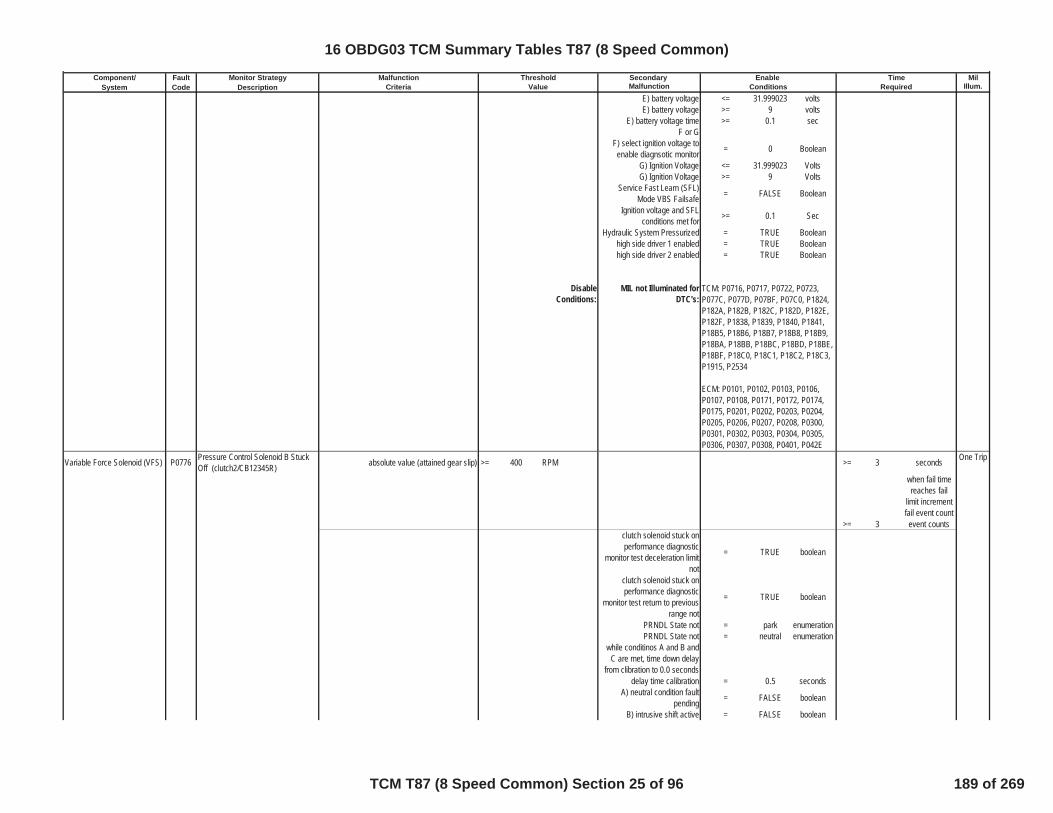
Component/ Fault Monitor Strategy Secondary MilSystem Code Description Malfunction Illum.
Malfunction Threshold Enable TimeCriteria Value Conditions Required
E) battery voltage <= 31.999023 voltsE) battery voltage >= 9 volts
E) battery voltage time >= 0.1 secF or G
F) select ignition voltage toenable diagnsotic monitor = 0 Boolean
G) Ignition Voltage <= 31.999023 VoltsG) Ignition Voltage >= 9 Volts
Service Fast Learn (SFL)Mode VBS Failsafe = FALSE Boolean
Ignition voltage and SFLconditions met for >= 0.1 Sec
Hydraulic System Pressurized = TRUE Booleanhigh side driver 1 enabled = TRUE Booleanhigh side driver 2 enabled = TRUE Boolean
DisableConditions:
MIL not Illuminated forDTC's:
Variable Force Solenoid (VFS) P0776 Pressure Control Solenoid B StuckOff (clutch2/CB12345R) absolute value (attained gear slip) >= 400 RPM >= 3 seconds One Trip
when fail timereaches fail
limit incrementfail event count
>= 3 event countsclutch solenoid stuck onperformance diagnostic
monitor test deceleration limitnot
= TRUE boolean
clutch solenoid stuck onperformance diagnostic
monitor test return to previousrange not
= TRUE boolean
PRNDL State not = park enumerationPRNDL State not = neutral enumeration
while conditinos A and B andC are met, time down delay
from clibration to 0.0 secondsdelay time calibration = 0.5 seconds
A) neutral condition faultpending = FALSE boolean
B) intrusive shift active = FALSE boolean
TCM: P0716, P0717, P0722, P0723,P077C, P077D, P07BF, P07C0, P1824,P182A, P182B, P182C, P182D, P182E,P182F, P1838, P1839, P1840, P1841,P18B5, P18B6, P18B7, P18B8, P18B9,P18BA, P18BB, P18BC, P18BD, P18BE,P18BF, P18C0, P18C1, P18C2, P18C3,P1915, P2534
ECM: P0101, P0102, P0103, P0106,P0107, P0108, P0171, P0172, P0174,P0175, P0201, P0202, P0203, P0204,P0205, P0206, P0207, P0208, P0300,P0301, P0302, P0303, P0304, P0305,P0306, P0307, P0308, P0401, P042E
16 OBDG03 TCM Summary Tables T87 (8 Speed Common)
TCM T87 (8 Speed Common) Section 25 of 96 189 of 269
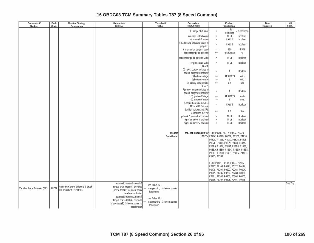
Component/ Fault Monitor Strategy Secondary MilSystem Code Description Malfunction Illum.
Malfunction Threshold Enable TimeCriteria Value Conditions Required
C) range shift state = shiftcomplete enumeration
intrusive shift allowed = TRUE booleanintrusive shift active = FALSE boolean
steady state pressure adapt inprogress = FALSE boolean
transmission output speed >= 100 RPMaccelerator pedal position >= 0.5004883 %
accelerator pedal position valid = TRUE Boolean
engine speed valid = TRUE BooleanD or E
D) select battery voltage toenable diagnsotic monitor = 0 Boolean
E) battery voltage <= 31.999023 voltsE) battery voltage >= 9 volts
E) battery voltage time >= 0.1 secF or G
F) select ignition voltage toenable diagnsotic monitor = 0 Boolean
G) Ignition Voltage <= 31.999023 VoltsG) Ignition Voltage >= 9 Volts
Service Fast Learn (SFL)Mode VBS Failsafe = FALSE Boolean
Ignition voltage and SFLconditions met for >= 0.1 Sec
Hydraulic System Pressurized = TRUE Booleanhigh side driver 1 enabled = TRUE Booleanhigh side driver 2 enabled = TRUE Boolean
DisableConditions:
MIL not Illuminated forDTC's:
Variable Force Solenoid (VFS) P0777 Pressure Control Solenoid B StuckOn (clutch2/CB12345R)
automatic transmission shifttorque phase test (A) or inertiaphase test (B) fail event count
deceleration limited
>=see Table 32in supportingdocuments
fail event counts
One Trip
automatic transmission shifttorque phase test (A) or inertia
phase test (B) fail event count nodeceleration
>=see Table 33in supportingdocuments
fail event counts
TCM: P0716, P0717, P0722, P0723,P077C, P077D, P07BF, P07C0, P1824,P182A, P182B, P182C, P182D, P182E,P182F, P1838, P1839, P1840, P1841,P18B5, P18B6, P18B7, P18B8, P18B9,P18BA, P18BB, P18BC, P18BD, P18BE,P18BF, P18C0, P18C1, P18C2, P18C3,P1915, P2534
ECM: P0101, P0102, P0103, P0106,P0107, P0108, P0171, P0172, P0174,P0175, P0201, P0202, P0203, P0204,P0205, P0206, P0207, P0208, P0300,P0301, P0302, P0303, P0304, P0305,P0306, P0307, P0308, P0401, P042E
16 OBDG03 TCM Summary Tables T87 (8 Speed Common)
TCM T87 (8 Speed Common) Section 26 of 96 190 of 269
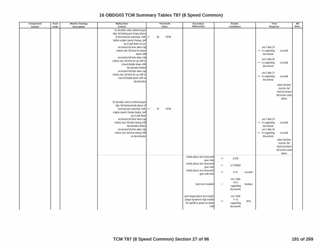
Component/ Fault Monitor Strategy Secondary MilSystem Code Description Malfunction Illum.
Malfunction Threshold Enable TimeCriteria Value Conditions Required
A) absolute value (attained gearslip), fail during post torque phase
of transmission automatic shift,before engine speed change, pull
up or pull down occurs
<= 40 RPM
increment fail time when slipcriteria met, fail time for power
down shift>=
see Table 29in supportingdocuments
seconds
increment fail time when slipcriteria met, fail time for up shift or
closed throttle down shiftdeceleration limited
>=see Table 30in supportingdocuments
seconds
increment fail time when slipcriteria met, fail time for up shift or
closed throttle down shift nodeceleration
>=see Table 31in supportingdocuments
seconds
when fail timereaches fail
limit incrementfail event count
aboveB) absolute value (command gear
slip), fail during inertia phase oftransmission automatic shift,
engine speed change begins, pullup or pull down
>= 70 RPM
increment fail time when slipcriteria met, fail time during shift
deceleration limited>=
see Table 35in supportingdocuments
seconds
increment fail time when slipcriteria met, fail time during shift
no deceleration>=
see Table 36in supportingdocuments
seconds
when fail timereaches fail
limit incrementfail event count
aboveinertia phase test measured
gear ratio >= 0.558
inertia phase test measuredgear ratio <= 4.7150002
inertia phase test measuredgear ratio time >= 0.15 seconds
clutch test enabled =
see Table10 in
supportingdocuments
boolean
post torque phase test enginetorque hysteresis high enablefor upshift or power on down
shift
>=
see Table11 in
supportingdocuments
N*m
16 OBDG03 TCM Summary Tables T87 (8 Speed Common)
TCM T87 (8 Speed Common) Section 27 of 96 191 of 269

Component/ Fault Monitor Strategy Secondary MilSystem Code Description Malfunction Illum.
Malfunction Threshold Enable TimeCriteria Value Conditions Required
post torque phase test enginetorque hysteresis low disablefor upshift or power on down
shift
>
see Table12 in
supportingdocuments
N*m
post torque phase test enginetorque hysteresis high enablefor closed throttle down shift
>=
see Table13 in
supportingdocuments
N*m
post torque phase test enginetorque hysteresis low disablefor closed throttle down shift
>
see Table14 in
supportingdocuments
N*m
inertia phase test enginetorque hysteresis high enablefor upshift or power on down
shift
>=
see Table15 in
supportingdocuments
N*m
inertia phase test enginetorque hysteresis low disablefor upshift or power on down
shift
>
see Table16 in
supportingdocuments
N*m
inertia phase test enginetorque hysteresis high enablefor closed throttle down shift
>=
see Table17 in
supportingdocuments
N*m
inertia phase test enginetorque hysteresis low disablefor closed throttle down shift
>
see Table18 in
supportingdocuments
N*m
off going clutch pressure <=
see Table37 in
supportingdocuments
kPa
off going clutch pressureclosed throttle down shift delay
time>=
see Table3 in
supportingdocuments
seconds
off going clutch pressureclosed power down shift delay
time>=
see Table39 in
supportingdocuments
seconds
off going clutch pressure upshift delay time >=
see Table60 in
supportingdocuments
seconds
16 OBDG03 TCM Summary Tables T87 (8 Speed Common)
TCM T87 (8 Speed Common) Section 28 of 96 192 of 269

Component/ Fault Monitor Strategy Secondary MilSystem Code Description Malfunction Illum.
Malfunction Threshold Enable TimeCriteria Value Conditions Required
on coming clutch pressure forup shift >=
see Table8 in
supportingdocuments
kPa
on coming clutch pressure fordown shift >=
see Table7 in
supportingdocuments
kPa
brake pedal position hysteresishigh disable >= 27.000427 %
brake pedal position hysteresislow enable <= 25 %
absolute value (attained gearslip) <= 40 RPM
shift type enable =
see Table45 in
supportingdocuments
boolean
clucth solenoid stuck offintrusive shift request not = TRUE boolean
traction control event testsuspend not = TRUE boolean
transmission output speed >= 100 RPM
accelerator pedal position valid = TRUE Boolean
engine speed valid = TRUE BooleanD or E
D) select battery voltage toenable diagnsotic monitor = 0 Boolean
E) battery voltage <= 31.999023 voltsE) battery voltage >= 9 volts
E) battery voltage time >= 0.1 secF or G
F) select ignition voltage toenable diagnsotic monitor = 0 Boolean
G) Ignition Voltage <= 31.999023 VoltsG) Ignition Voltage >= 9 Volts
Service Fast Learn (SFL)Mode VBS Failsafe = FALSE Boolean
Ignition voltage and SFLconditions met for >= 0.1 Sec
Hydraulic System Pressurized = TRUE Booleanhigh side driver 1 enabled = TRUE Booleanhigh side driver 2 enabled = TRUE Boolean
16 OBDG03 TCM Summary Tables T87 (8 Speed Common)
TCM T87 (8 Speed Common) Section 29 of 96 193 of 269

Component/ Fault Monitor Strategy Secondary MilSystem Code Description Malfunction Illum.
Malfunction Threshold Enable TimeCriteria Value Conditions Required
DisableConditions:
MIL not Illuminated forDTC's:
Transmission Output SpeedSensor (TOSS) P077C Output Speed Sensor Circuit Low TOSS Analog Signal Voltage <= 0.25 Volts >= 5.00E-02 sec One Trip
P077C Status is not =Test FailedThis Key On
or Fault Active
If the above conditons have beenmet, increment the P077C Fail
Counter
DTC P077C Sets when the FailCounter >= 16
Counts (6.25mseccontinuous)
P077C Enable Calibration = 1Service mode $04 active and
end of trip pocessing active = FALSE Boolean
Ignition Voltage Hyst Hi(enabled above this value) > 5 Volts
Ignition Voltage Hyst Lodisabled below this value) <= 2 Volts
Service Fast Learn (SFL)Mode VBS Failsafe = FALSE Boolean
Battery Voltage Max (disabledabove this value) <= 31.999023 Volts
Battery Voltage Min (disabledbelow this value) <= 10 Volts
Ignition Voltage Min (disabledbelow this value) >= 10 Volts
for voltage stablity time >= 5 seconds
DisableConditions:
MIL not Illuminated forDTC's:
Transmission Output SpeedSensor (TOSS) P077D Output Speed Sensor Circuit High TOSS Analog Signal Voltage >= 4.75 Volts >= 5.00E-02 sec One Trip
P077D Status is not =Test FailedThis Key On
or Fault Active
TCM: P077D
TCM: P0716, P0717, P0722, P0723,P077C, P077D, P07BF, P07C0, P1824,P182A, P182B, P182C, P182D, P182E,P182F, P1838, P1839, P1840, P1841,P18B5, P18B6, P18B7, P18B8, P18B9,P18BA, P18BB, P18BC, P18BD, P18BE,P18BF, P18C0, P18C1, P18C2, P18C3,P1915, P2534
ECM: P0101, P0102, P0103, P0106,P0107, P0108, P0171, P0172, P0174,P0175, P0201, P0202, P0203, P0204,P0205, P0206, P0207, P0208, P0300,P0301, P0302, P0303, P0304, P0305,P0306, P0307, P0308, P0401, P042E
16 OBDG03 TCM Summary Tables T87 (8 Speed Common)
TCM T87 (8 Speed Common) Section 30 of 96 194 of 269

Component/ Fault Monitor Strategy Secondary MilSystem Code Description Malfunction Illum.
Malfunction Threshold Enable TimeCriteria Value Conditions Required
If the above conditons have beenmet, increment the P077D Fail
Counter
DTC P077D Sets when the FailCounter >= 16
Counts (12.5mseccontinuous)
P077D Enable Calibration = 1Service mode $04 active and
end of trip pocessing active = FALSE Boolean
Ignition Voltage Hyst Hi(enabled above this value) > 5 Volts
Ignition Voltage Hyst Lodisabled below this value) <= 2 Volts
Service Fast Learn (SFL)Mode VBS Failsafe = FALSE Boolean
Battery Voltage Max (disabledabove this value) <= 31.999023 Volts
Battery Voltage Min (disabledbelow this value) <= 10 Volts
Ignition Voltage Min (disabledbelow this value) >= 10 Volts
for voltage stablity time >= 5 seconds
DisableConditions:
MIL not Illuminated forDTC's:
Variable Force Solenoid (VFS) P0796 Pressure Control Solenoid C StuckOff (clutch3/C13567) absolute value (attained gear slip) >= 400 RPM >= 3 seconds One Trip
when fail timereaches fail
limit incrementfail event count
>= 3 event countsclutch solenoid stuck onperformance diagnostic
monitor test deceleration limitnot
= TRUE boolean
clutch solenoid stuck onperformance diagnostic
monitor test return to previousrange not
= TRUE boolean
PRNDL State not = park enumerationPRNDL State not = neutral enumeration
while conditinos A and B andC are met, time down delay
from clibration to 0.0 secondsdelay time calibration = 0.5 seconds
A) neutral condition faultpending = FALSE boolean
B) intrusive shift active = FALSE boolean
C) range shift state = shiftcomplete enumeration
intrusive shift allowed = TRUE booleanintrusive shift active = FALSE boolean
TCM: P077C
16 OBDG03 TCM Summary Tables T87 (8 Speed Common)
TCM T87 (8 Speed Common) Section 31 of 96 195 of 269
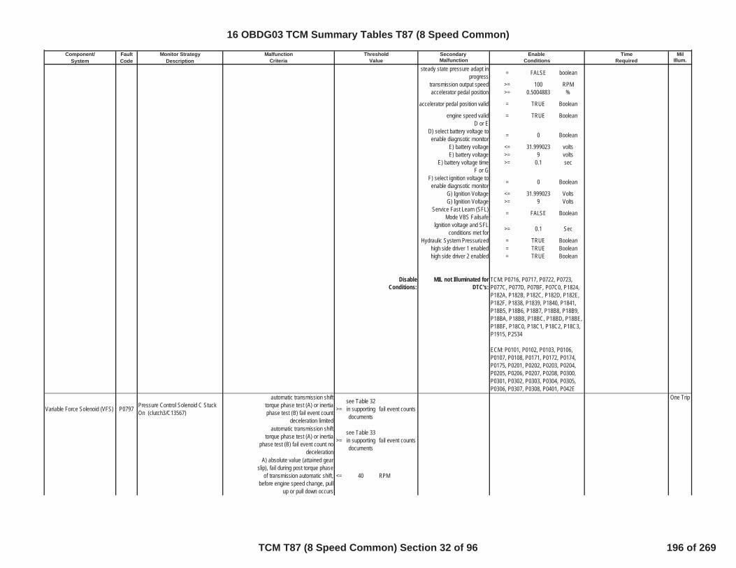
Component/ Fault Monitor Strategy Secondary MilSystem Code Description Malfunction Illum.
Malfunction Threshold Enable TimeCriteria Value Conditions Required
steady state pressure adapt inprogress = FALSE boolean
transmission output speed >= 100 RPMaccelerator pedal position >= 0.5004883 %
accelerator pedal position valid = TRUE Boolean
engine speed valid = TRUE BooleanD or E
D) select battery voltage toenable diagnsotic monitor = 0 Boolean
E) battery voltage <= 31.999023 voltsE) battery voltage >= 9 volts
E) battery voltage time >= 0.1 secF or G
F) select ignition voltage toenable diagnsotic monitor = 0 Boolean
G) Ignition Voltage <= 31.999023 VoltsG) Ignition Voltage >= 9 Volts
Service Fast Learn (SFL)Mode VBS Failsafe = FALSE Boolean
Ignition voltage and SFLconditions met for >= 0.1 Sec
Hydraulic System Pressurized = TRUE Booleanhigh side driver 1 enabled = TRUE Booleanhigh side driver 2 enabled = TRUE Boolean
DisableConditions:
MIL not Illuminated forDTC's:
Variable Force Solenoid (VFS) P0797 Pressure Control Solenoid C StuckOn (clutch3/C13567)
automatic transmission shifttorque phase test (A) or inertiaphase test (B) fail event count
deceleration limited
>=see Table 32in supportingdocuments
fail event counts
One Trip
automatic transmission shifttorque phase test (A) or inertia
phase test (B) fail event count nodeceleration
>=see Table 33in supportingdocuments
fail event counts
A) absolute value (attained gearslip), fail during post torque phase
of transmission automatic shift,before engine speed change, pull
up or pull down occurs
<= 40 RPM
TCM: P0716, P0717, P0722, P0723,P077C, P077D, P07BF, P07C0, P1824,P182A, P182B, P182C, P182D, P182E,P182F, P1838, P1839, P1840, P1841,P18B5, P18B6, P18B7, P18B8, P18B9,P18BA, P18BB, P18BC, P18BD, P18BE,P18BF, P18C0, P18C1, P18C2, P18C3,P1915, P2534
ECM: P0101, P0102, P0103, P0106,P0107, P0108, P0171, P0172, P0174,P0175, P0201, P0202, P0203, P0204,P0205, P0206, P0207, P0208, P0300,P0301, P0302, P0303, P0304, P0305,P0306, P0307, P0308, P0401, P042E
16 OBDG03 TCM Summary Tables T87 (8 Speed Common)
TCM T87 (8 Speed Common) Section 32 of 96 196 of 269
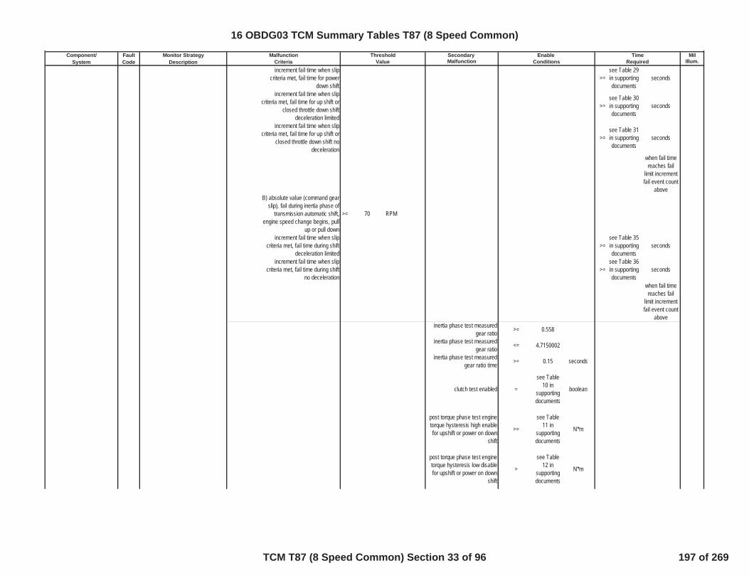
Component/ Fault Monitor Strategy Secondary MilSystem Code Description Malfunction Illum.
Malfunction Threshold Enable TimeCriteria Value Conditions Requiredincrement fail time when slip
criteria met, fail time for powerdown shift
>=see Table 29in supportingdocuments
seconds
increment fail time when slipcriteria met, fail time for up shift or
closed throttle down shiftdeceleration limited
>=see Table 30in supportingdocuments
seconds
increment fail time when slipcriteria met, fail time for up shift or
closed throttle down shift nodeceleration
>=see Table 31in supportingdocuments
seconds
when fail timereaches fail
limit incrementfail event count
aboveB) absolute value (command gear
slip), fail during inertia phase oftransmission automatic shift,
engine speed change begins, pullup or pull down
>= 70 RPM
increment fail time when slipcriteria met, fail time during shift
deceleration limited>=
see Table 35in supportingdocuments
seconds
increment fail time when slipcriteria met, fail time during shift
no deceleration>=
see Table 36in supportingdocuments
seconds
when fail timereaches fail
limit incrementfail event count
aboveinertia phase test measured
gear ratio >= 0.558
inertia phase test measuredgear ratio <= 4.7150002
inertia phase test measuredgear ratio time >= 0.15 seconds
clutch test enabled =
see Table10 in
supportingdocuments
boolean
post torque phase test enginetorque hysteresis high enablefor upshift or power on down
shift
>=
see Table11 in
supportingdocuments
N*m
post torque phase test enginetorque hysteresis low disablefor upshift or power on down
shift
>
see Table12 in
supportingdocuments
N*m
16 OBDG03 TCM Summary Tables T87 (8 Speed Common)
TCM T87 (8 Speed Common) Section 33 of 96 197 of 269
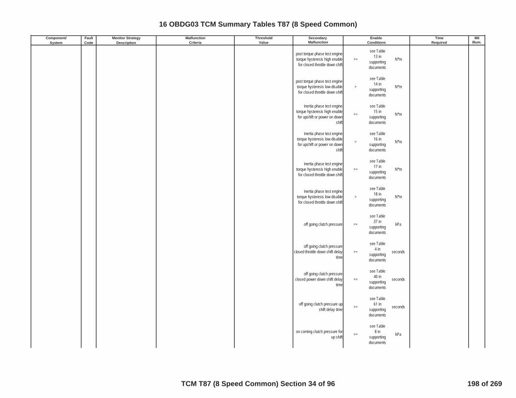
Component/ Fault Monitor Strategy Secondary MilSystem Code Description Malfunction Illum.
Malfunction Threshold Enable TimeCriteria Value Conditions Required
post torque phase test enginetorque hysteresis high enablefor closed throttle down shift
>=
see Table13 in
supportingdocuments
N*m
post torque phase test enginetorque hysteresis low disablefor closed throttle down shift
>
see Table14 in
supportingdocuments
N*m
inertia phase test enginetorque hysteresis high enablefor upshift or power on down
shift
>=
see Table15 in
supportingdocuments
N*m
inertia phase test enginetorque hysteresis low disablefor upshift or power on down
shift
>
see Table16 in
supportingdocuments
N*m
inertia phase test enginetorque hysteresis high enablefor closed throttle down shift
>=
see Table17 in
supportingdocuments
N*m
inertia phase test enginetorque hysteresis low disablefor closed throttle down shift
>
see Table18 in
supportingdocuments
N*m
off going clutch pressure <=
see Table37 in
supportingdocuments
kPa
off going clutch pressureclosed throttle down shift delay
time>=
see Table4 in
supportingdocuments
seconds
off going clutch pressureclosed power down shift delay
time>=
see Table40 in
supportingdocuments
seconds
off going clutch pressure upshift delay time >=
see Table61 in
supportingdocuments
seconds
on coming clutch pressure forup shift >=
see Table8 in
supportingdocuments
kPa
16 OBDG03 TCM Summary Tables T87 (8 Speed Common)
TCM T87 (8 Speed Common) Section 34 of 96 198 of 269

Component/ Fault Monitor Strategy Secondary MilSystem Code Description Malfunction Illum.
Malfunction Threshold Enable TimeCriteria Value Conditions Required
on coming clutch pressure fordown shift >=
see Table7 in
supportingdocuments
kPa
brake pedal position hysteresishigh disable >= 27.000427 %
brake pedal position hysteresislow enable <= 25 %
absolute value (attained gearslip) <= 40 RPM
shift type enable =
see Table45 in
supportingdocuments
boolean
clucth solenoid stuck offintrusive shift request not = TRUE boolean
traction control event testsuspend not = TRUE boolean
transmission output speed >= 100 RPM
accelerator pedal position valid = TRUE Boolean
engine speed valid = TRUE BooleanD or E
D) select battery voltage toenable diagnsotic monitor = 0 Boolean
E) battery voltage <= 31.999023 voltsE) battery voltage >= 9 volts
E) battery voltage time >= 0.1 secF or G
F) select ignition voltage toenable diagnsotic monitor = 0 Boolean
G) Ignition Voltage <= 31.999023 VoltsG) Ignition Voltage >= 9 Volts
Service Fast Learn (SFL)Mode VBS Failsafe = FALSE Boolean
Ignition voltage and SFLconditions met for >= 0.1 Sec
Hydraulic System Pressurized = TRUE Booleanhigh side driver 1 enabled = TRUE Booleanhigh side driver 2 enabled = TRUE Boolean
16 OBDG03 TCM Summary Tables T87 (8 Speed Common)
TCM T87 (8 Speed Common) Section 35 of 96 199 of 269
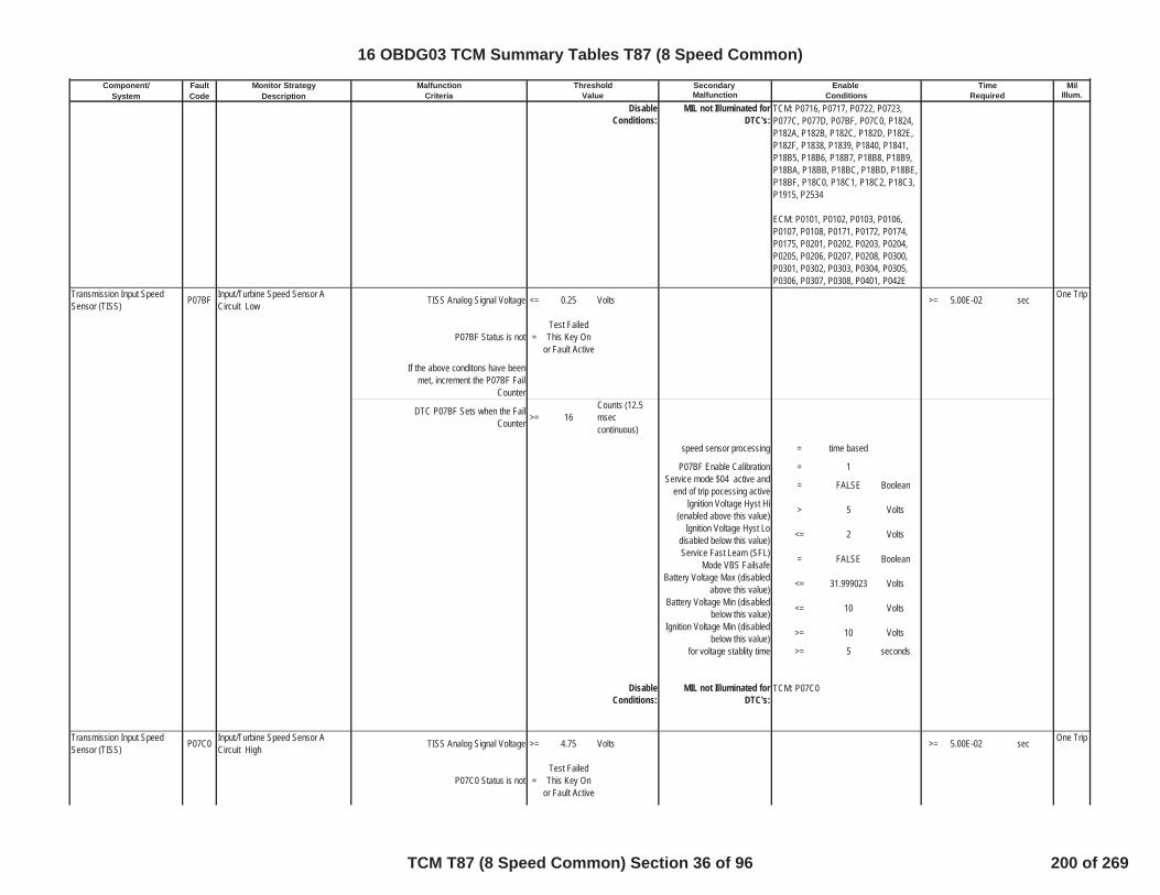
Component/ Fault Monitor Strategy Secondary MilSystem Code Description Malfunction Illum.
Malfunction Threshold Enable TimeCriteria Value Conditions Required
DisableConditions:
MIL not Illuminated forDTC's:
Transmission Input SpeedSensor (TISS) P07BF Input/Turbine Speed Sensor A
Circuit Low TISS Analog Signal Voltage <= 0.25 Volts >= 5.00E-02 sec One Trip
P07BF Status is not =Test FailedThis Key On
or Fault Active
If the above conditons have beenmet, increment the P07BF Fail
Counter
DTC P07BF Sets when the FailCounter >= 16
Counts (12.5mseccontinuous)
speed sensor processing = time based
P07BF Enable Calibration = 1Service mode $04 active and
end of trip pocessing active = FALSE Boolean
Ignition Voltage Hyst Hi(enabled above this value) > 5 Volts
Ignition Voltage Hyst Lodisabled below this value) <= 2 Volts
Service Fast Learn (SFL)Mode VBS Failsafe = FALSE Boolean
Battery Voltage Max (disabledabove this value) <= 31.999023 Volts
Battery Voltage Min (disabledbelow this value) <= 10 Volts
Ignition Voltage Min (disabledbelow this value) >= 10 Volts
for voltage stablity time >= 5 seconds
DisableConditions:
MIL not Illuminated forDTC's:
Transmission Input SpeedSensor (TISS) P07C0 Input/Turbine Speed Sensor A
Circuit High TISS Analog Signal Voltage >= 4.75 Volts >= 5.00E-02 sec One Trip
P07C0 Status is not =Test FailedThis Key On
or Fault Active
TCM: P0716, P0717, P0722, P0723,P077C, P077D, P07BF, P07C0, P1824,P182A, P182B, P182C, P182D, P182E,P182F, P1838, P1839, P1840, P1841,P18B5, P18B6, P18B7, P18B8, P18B9,P18BA, P18BB, P18BC, P18BD, P18BE,P18BF, P18C0, P18C1, P18C2, P18C3,P1915, P2534
ECM: P0101, P0102, P0103, P0106,P0107, P0108, P0171, P0172, P0174,P0175, P0201, P0202, P0203, P0204,P0205, P0206, P0207, P0208, P0300,P0301, P0302, P0303, P0304, P0305,P0306, P0307, P0308, P0401, P042E
TCM: P07C0
16 OBDG03 TCM Summary Tables T87 (8 Speed Common)
TCM T87 (8 Speed Common) Section 36 of 96 200 of 269
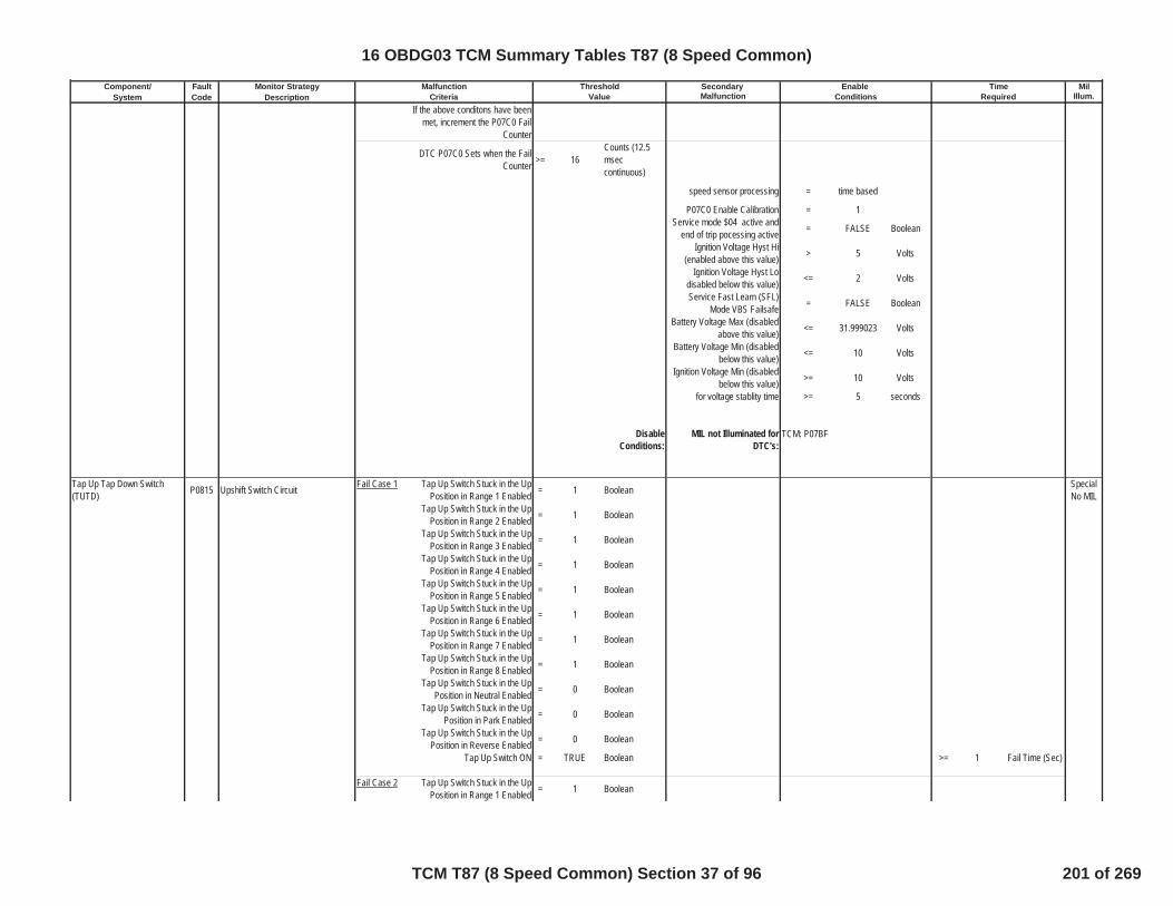
Component/ Fault Monitor Strategy Secondary MilSystem Code Description Malfunction Illum.
Malfunction Threshold Enable TimeCriteria Value Conditions Required
If the above conditons have beenmet, increment the P07C0 Fail
Counter
DTC P07C0 Sets when the FailCounter >= 16
Counts (12.5mseccontinuous)
speed sensor processing = time based
P07C0 Enable Calibration = 1Service mode $04 active and
end of trip pocessing active = FALSE Boolean
Ignition Voltage Hyst Hi(enabled above this value) > 5 Volts
Ignition Voltage Hyst Lodisabled below this value) <= 2 Volts
Service Fast Learn (SFL)Mode VBS Failsafe = FALSE Boolean
Battery Voltage Max (disabledabove this value) <= 31.999023 Volts
Battery Voltage Min (disabledbelow this value) <= 10 Volts
Ignition Voltage Min (disabledbelow this value) >= 10 Volts
for voltage stablity time >= 5 seconds
DisableConditions:
MIL not Illuminated forDTC's:
Tap Up Tap Down Switch(TUTD) P0815 Upshift Switch Circuit Fail Case 1 Tap Up Switch Stuck in the Up
Position in Range 1 Enabled = 1 Boolean SpecialNo MIL
Tap Up Switch Stuck in the UpPosition in Range 2 Enabled = 1 Boolean
Tap Up Switch Stuck in the UpPosition in Range 3 Enabled = 1 Boolean
Tap Up Switch Stuck in the UpPosition in Range 4 Enabled = 1 Boolean
Tap Up Switch Stuck in the UpPosition in Range 5 Enabled = 1 Boolean
Tap Up Switch Stuck in the UpPosition in Range 6 Enabled = 1 Boolean
Tap Up Switch Stuck in the UpPosition in Range 7 Enabled = 1 Boolean
Tap Up Switch Stuck in the UpPosition in Range 8 Enabled = 1 Boolean
Tap Up Switch Stuck in the UpPosition in Neutral Enabled = 0 Boolean
Tap Up Switch Stuck in the UpPosition in Park Enabled = 0 Boolean
Tap Up Switch Stuck in the UpPosition in Reverse Enabled = 0 Boolean
Tap Up Switch ON = TRUE Boolean >= 1 Fail Time (Sec)
Fail Case 2 Tap Up Switch Stuck in the UpPosition in Range 1 Enabled = 1 Boolean
TCM: P07BF
16 OBDG03 TCM Summary Tables T87 (8 Speed Common)
TCM T87 (8 Speed Common) Section 37 of 96 201 of 269
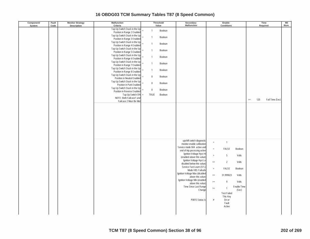
Component/ Fault Monitor Strategy Secondary MilSystem Code Description Malfunction Illum.
Malfunction Threshold Enable TimeCriteria Value Conditions Required
Tap Up Switch Stuck in the UpPosition in Range 2 Enabled = 1 Boolean
Tap Up Switch Stuck in the UpPosition in Range 3 Enabled = 1 Boolean
Tap Up Switch Stuck in the UpPosition in Range 4 Enabled = 1 Boolean
Tap Up Switch Stuck in the UpPosition in Range 5 Enabled = 1 Boolean
Tap Up Switch Stuck in the UpPosition in Range 6 Enabled = 1 Boolean
Tap Up Switch Stuck in the UpPosition in Range 7 Enabled = 1 Boolean
Tap Up Switch Stuck in the UpPosition in Range 8 Enabled = 1 Boolean
Tap Up Switch Stuck in the UpPosition in Neutral Enabled = 0 Boolean
Tap Up Switch Stuck in the UpPosition in Park Enabled = 0 Boolean
Tap Up Switch Stuck in the UpPosition in Reverse Enabled = 0 Boolean
Tap Up Switch ON = TRUE BooleanNOTE: Both Failcase1 and
Failcase 2 Must Be Met >= 120 Fail Time (Sec)
upshift switch diagnosticmonitor enable calibration = 1
Service mode $04 active andend of trip pocessing active = FALSE Boolean
Ignition Voltage Hyst Hi(enabled above this value) > 5 Volts
Ignition Voltage Hyst Lodisabled below this value) <= 2 Volts
Service Fast Learn (SFL)Mode VBS Failsafe = FALSE Boolean
Ignition Voltage Max (disabledabove this value) <= 31.999023 Volts
Ignition Voltage Min (enabledabove this value) >= 9 Volts
Time Since Last RangeChange >= 1 Enable Time
(Sec)
P0815 Status is
Test FailedThis Key
On orFaultActive
16 OBDG03 TCM Summary Tables T87 (8 Speed Common)
TCM T87 (8 Speed Common) Section 38 of 96 202 of 269
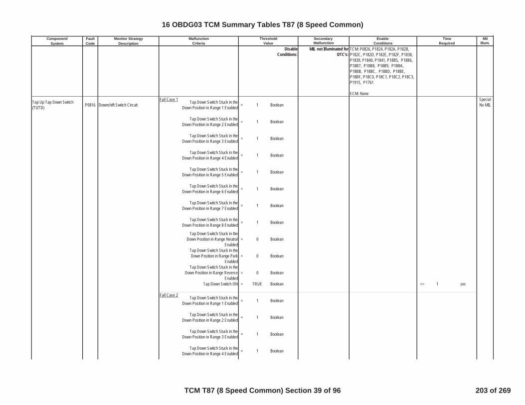
Component/ Fault Monitor Strategy Secondary MilSystem Code Description Malfunction Illum.
Malfunction Threshold Enable TimeCriteria Value Conditions Required
DisableConditions:
MIL not Illuminated forDTC's:
Tap Up Tap Down Switch(TUTD) P0816 Downshift Switch Circuit
Fail Case 1 Tap Down Switch Stuck in theDown Position in Range 1 Enabled = 1 Boolean
SpecialNo MIL
Tap Down Switch Stuck in theDown Position in Range 2 Enabled = 1 Boolean
Tap Down Switch Stuck in theDown Position in Range 3 Enabled = 1 Boolean
Tap Down Switch Stuck in theDown Position in Range 4 Enabled = 1 Boolean
Tap Down Switch Stuck in theDown Position in Range 5 Enabled = 1 Boolean
Tap Down Switch Stuck in theDown Position in Range 6 Enabled = 1 Boolean
Tap Down Switch Stuck in theDown Position in Range 7 Enabled = 1 Boolean
Tap Down Switch Stuck in theDown Position in Range 8 Enabled = 1 Boolean
Tap Down Switch Stuck in theDown Position in Range Neutral
Enabled= 0 Boolean
Tap Down Switch Stuck in theDown Position in Range Park
Enabled= 0 Boolean
Tap Down Switch Stuck in theDown Position in Range Reverse
Enabled= 0 Boolean
Tap Down Switch ON = TRUE Boolean >= 1 sec
Fail Case 2 Tap Down Switch Stuck in theDown Position in Range 1 Enabled = 1 Boolean
Tap Down Switch Stuck in theDown Position in Range 2 Enabled = 1 Boolean
Tap Down Switch Stuck in theDown Position in Range 3 Enabled = 1 Boolean
Tap Down Switch Stuck in theDown Position in Range 4 Enabled = 1 Boolean
TCM: P0826, P1824, P182A, P182B,P182C, P182D, P182E, P182F, P1838,P1839, P1840, P1841, P18B5, P18B6,P18B7, P18B8, P18B9, P18BA,P18BB, P18BC, P18BD, P18BE,P18BF, P18C0, P18C1, P18C2, P18C3,P1915, P1761
ECM: None
16 OBDG03 TCM Summary Tables T87 (8 Speed Common)
TCM T87 (8 Speed Common) Section 39 of 96 203 of 269
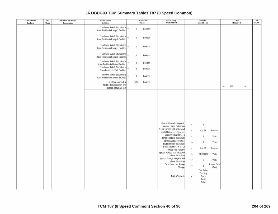
Component/ Fault Monitor Strategy Secondary MilSystem Code Description Malfunction Illum.
Malfunction Threshold Enable TimeCriteria Value Conditions Required
Tap Down Switch Stuck in theDown Position in Range 5 Enabled = 1 Boolean
Tap Down Switch Stuck in theDown Position in Range 6 Enabled = 1 Boolean
Tap Down Switch Stuck in theDown Position in Range 7 Enabled = 1 Boolean
Tap Down Switch Stuck in theDown Position in Range 8 Enabled = 1 Boolean
Tap Down Switch Stuck in theDown Position in Neutral Enabled = 0 Boolean
Tap Down Switch Stuck in theDown Position in Park Enabled = 0 Boolean
Tap Down Switch Stuck in theDown Position in Reverse Enabled = 0 Boolean
Tap Down Switch ON = TRUE BooleanNOTE: Both Failcase1 and
Failcase 2 Must Be Met >= 120 sec
downshift switch diagnosticmonitor enable calibration = 1
Service mode $04 active andend of trip pocessing active = FALSE Boolean
Ignition Voltage Hyst Hi(enabled above this value) > 5 Volts
Ignition Voltage Hyst Lodisabled below this value) <= 2 Volts
Service Fast Learn (SFL)Mode VBS Failsafe = FALSE Boolean
Ignition Voltage Max (disabledabove this value) <= 31.999023 Volts
Ignition Voltage Min (enabledabove this value) >= 9 Volts
Time Since Last RangeChange >= 1 Enable Time
(Sec)
P0816 Status is
Test FailedThis Key
On orFaultActive
16 OBDG03 TCM Summary Tables T87 (8 Speed Common)
TCM T87 (8 Speed Common) Section 40 of 96 204 of 269

Component/ Fault Monitor Strategy Secondary MilSystem Code Description Malfunction Illum.
Malfunction Threshold Enable TimeCriteria Value Conditions Required
DisableConditions:
MIL not Illuminated forDTC's:
Tap Up Tap Down Switch(TUTD) P0826 Up and Down Shift Switch Circuit TUTD Circuit Reads Invalid
Voltage = TRUE Boolean >= 60 Fail Time (Sec) SpecialNo MIL
Service mode $04 active andend of trip pocessing active = FALSE Boolean
upshift downshift switch circuitdiagnostic monitor enable
calibration= 1
Ignition Voltage Hyst Hi(enabled above this value) > 5 Volts
Ignition Voltage Hyst Lodisabled below this value) <= 2 Volts
Service Fast Learn (SFL)Mode VBS Failsafe = FALSE Boolean
Ignition Voltage Max (disabledabove this value) <= 31.999023 Volts
Ignition Voltage Min (enabledabove this value) >= 9 Volts
P0826 Status is
Test FailedThis Key
On orFaultActive
DisableConditions:
MIL not Illuminated forDTC's:
Variable Force Solenoid (VFS) P0960Pressure Control Solenoid A ControlCircuit Open(clutch1/CB1278R VFS)
The HWIO reports open crcuiterror flag = TRUE Boolean >= 0.3 Fail Time (Sec)
One Trip
outof 0.5 Sample Time
(Sec)diagnostic monitor enable
calibration = TRUE Boolean
VFS source must be high sidedriver 1 or 2 or 3
high side driver VFS source is = CeTSCR_e_HSD2 enumeration
high side driver VFS sourceenabled = TRUE Boolean
controller power mode state isignition or accessory = TRUE Boolean
battery voltage in range forstability time
battery voltage stability time >= 1 secondsbattery voltage >= 8 voltsbattery voltage <= 32 Volts
TCM: P0826, P1824, P182A, P182B,P182C, P182D, P182E, P182F, P1838,P1839, P1840, P1841, P18B5, P18B6,P18B7, P18B8, P18B9, P18BA,P18BB, P18BC, P18BD, P18BE,P18BF, P18C0, P18C1, P18C2, P18C3,P1915, P1761
ECM: None
16 OBDG03 TCM Summary Tables T87 (8 Speed Common)
TCM T87 (8 Speed Common) Section 41 of 96 205 of 269

Component/ Fault Monitor Strategy Secondary MilSystem Code Description Malfunction Illum.
Malfunction Threshold Enable TimeCriteria Value Conditions Required
DisableConditions:
MIL not Illuminated forDTC's:
Variable Force Solenoid (VFS) P0962Pressure Control Solenoid A ControlCircuit Low(clutch1/CB1278R VFS)
The HWIO reports open crcuiterror flag = TRUE Boolean >= 0.3 Fail Time (Sec)
One Trip
outof 0.5 Sample Time
(Sec)diagnostic monitor enable
calibration = TRUE Boolean
VFS source must be high sidedriver 1 or 2 or 3
high side driver VFS source is = CeTSCR_e_HSD2 enumeration
high side driver VFS sourceenabled = TRUE Boolean
controller power mode state isignition or accessory = TRUE Boolean
battery voltage in range forstability time
battery voltage stability time >= 1 secondsbattery voltage >= 8 voltsbattery voltage <= 32 Volts
DisableConditions:
MIL not Illuminated forDTC's:
Variable Force Solenoid (VFS) P0963Pressure Control Solenoid A ControlCircuit High(clutch1/CB1278R VFS)
The HWIO reports open crcuiterror flag = TRUE Boolean >= 0.3 Fail Time (Sec)
One Trip
outof 0.5 Sample Time
(Sec)diagnostic monitor enable
calibration = TRUE Boolean
VFS source must be high sidedriver 1 or 2 or 3
high side driver VFS source is = CeTSCR_e_HSD2 enumeration
high side driver VFS sourceenabled = TRUE Boolean
controller power mode state isignition or accessory = TRUE Boolean
battery voltage in range forstability time
battery voltage stability time >= 1 secondsbattery voltage >= 8 voltsbattery voltage <= 32 Volts
TCM: None
ECM: None
TCM: None
ECM: None
16 OBDG03 TCM Summary Tables T87 (8 Speed Common)
TCM T87 (8 Speed Common) Section 42 of 96 206 of 269
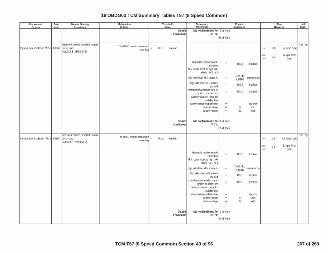
Component/ Fault Monitor Strategy Secondary MilSystem Code Description Malfunction Illum.
Malfunction Threshold Enable TimeCriteria Value Conditions Required
DisableConditions:
MIL not Illuminated forDTC's:
Variable Force Solenoid (VFS) P0964Pressure Control Solenoid B ControlCircuit Open(clutch2/CB12345R VFS)
The HWIO reports open crcuiterror flag = TRUE Boolean >= 0.3 Fail Time (Sec)
One Trip
outof 0.5 Sample Time
(Sec)diagnostic monitor enable
calibration = TRUE Boolean
VFS source must be high sidedriver 1 or 2 or 3
high side driver VFS source is = CeTSCR_e_HSD2 enumeration
high side driver VFS sourceenabled = TRUE Boolean
controller power mode state isignition or accessory = TRUE Boolean
battery voltage in range forstability time
battery voltage stability time >= 1 secondsbattery voltage >= 8 voltsbattery voltage <= 32 Volts
DisableConditions:
MIL not Illuminated forDTC's:
Variable Force Solenoid (VFS) P0966Pressure Control Solenoid B ControlCircuit Low(clutch2/CB12345R VFS)
The HWIO reports open crcuiterror flag = TRUE Boolean >= 0.3 Fail Time (Sec)
One Trip
outof 0.5 Sample Time
(Sec)diagnostic monitor enable
calibration = TRUE Boolean
VFS source must be high sidedriver 1 or 2 or 3
high side driver VFS source is = CeTSCR_e_HSD2 enumeration
high side driver VFS sourceenabled = TRUE Boolean
controller power mode state isignition or accessory = TRUE Boolean
battery voltage in range forstability time
battery voltage stability time >= 1 secondsbattery voltage >= 8 voltsbattery voltage <= 32 Volts
DisableConditions:
MIL not Illuminated forDTC's:
TCM: None
ECM: None
TCM: None
ECM: None
TCM: None
ECM: None
16 OBDG03 TCM Summary Tables T87 (8 Speed Common)
TCM T87 (8 Speed Common) Section 43 of 96 207 of 269

Component/ Fault Monitor Strategy Secondary MilSystem Code Description Malfunction Illum.
Malfunction Threshold Enable TimeCriteria Value Conditions Required
Variable Force Solenoid (VFS) P0967Pressure Control Solenoid B ControlCircuit High(clutch2/CB12345R VFS)
The HWIO reports open crcuiterror flag = TRUE Boolean >= 0.3 Fail Time (Sec)
One Trip
outof 0.5 Sample Time
(Sec)diagnostic monitor enable
calibration = TRUE Boolean
VFS source must be high sidedriver 1 or 2 or 3
high side driver VFS source is = CeTSCR_e_HSD2 enumeration
high side driver VFS sourceenabled = TRUE Boolean
controller power mode state isignition or accessory = TRUE Boolean
battery voltage in range forstability time
battery voltage stability time >= 1 secondsbattery voltage >= 8 voltsbattery voltage <= 32 Volts
DisableConditions:
MIL not Illuminated forDTC's:
Variable Force Solenoid (VFS) P0968Pressure Control Solenoid C ControlCircuit Open(clutch3/C13567 VFS)
The HWIO reports open crcuiterror flag = TRUE Boolean >= 0.3 Fail Time (Sec)
One Trip
outof 0.5 Sample Time
(Sec)diagnostic monitor enable
calibration = TRUE Boolean
VFS source must be high sidedriver 1 or 2 or 3
high side driver VFS source is = CeTSCR_e_HSD2 enumeration
high side driver VFS sourceenabled = TRUE Boolean
controller power mode state isignition or accessory = TRUE Boolean
battery voltage in range forstability time
battery voltage stability time >= 1 secondsbattery voltage >= 8 voltsbattery voltage <= 32 Volts
DisableConditions:
MIL not Illuminated forDTC's:
Variable Force Solenoid (VFS) P0970Pressure Control Solenoid C ControlCircuit Low(clutch3/C13567 VFS)
The HWIO reports open crcuiterror flag = TRUE Boolean >= 0.3 Fail Time (Sec)
One Trip
outof 0.5 Sample Time
(Sec)
TCM: None
ECM: None
TCM: None
ECM: None
16 OBDG03 TCM Summary Tables T87 (8 Speed Common)
TCM T87 (8 Speed Common) Section 44 of 96 208 of 269

Component/ Fault Monitor Strategy Secondary MilSystem Code Description Malfunction Illum.
Malfunction Threshold Enable TimeCriteria Value Conditions Required
diagnostic monitor enablecalibration = TRUE Boolean
VFS source must be high sidedriver 1 or 2 or 3
high side driver VFS source is = CeTSCR_e_HSD2 enumeration
high side driver VFS sourceenabled = TRUE Boolean
controller power mode state isignition or accessory = TRUE Boolean
battery voltage in range forstability time
battery voltage stability time >= 1 secondsbattery voltage >= 8 voltsbattery voltage <= 32 Volts
DisableConditions:
MIL not Illuminated forDTC's:
Variable Force Solenoid (VFS) P0971Pressure Control Solenoid C ControlCircuit High(clutch3/C13567 VFS)
The HWIO reports open crcuiterror flag = TRUE Boolean >= 0.3 Fail Time (Sec)
One Trip
outof 0.5 Sample Time
(Sec)diagnostic monitor enable
calibration = TRUE Boolean
VFS source must be high sidedriver 1 or 2 or 3
high side driver VFS source is = CeTSCR_e_HSD2 enumeration
high side driver VFS sourceenabled = TRUE Boolean
controller power mode state isignition or accessory = TRUE Boolean
battery voltage in range forstability time
battery voltage stability time >= 1 secondsbattery voltage >= 8 voltsbattery voltage <= 32 Volts
DisableConditions:
MIL not Illuminated forDTC's:
Transmission Control Module(TCM) P16E9 Transmission Control Module
secondary micro processorhardware serial peripheral device
fault active= TRUE Boolean
One Trip
secondary micro processorhardware serial peripheral device
fault active previous loop= TRUE Boolean
Service mode $04 active andend of trip pocessing active = FALSE Boolean
TCM: None
ECM: None
TCM: None
ECM: None
16 OBDG03 TCM Summary Tables T87 (8 Speed Common)
TCM T87 (8 Speed Common) Section 45 of 96 209 of 269
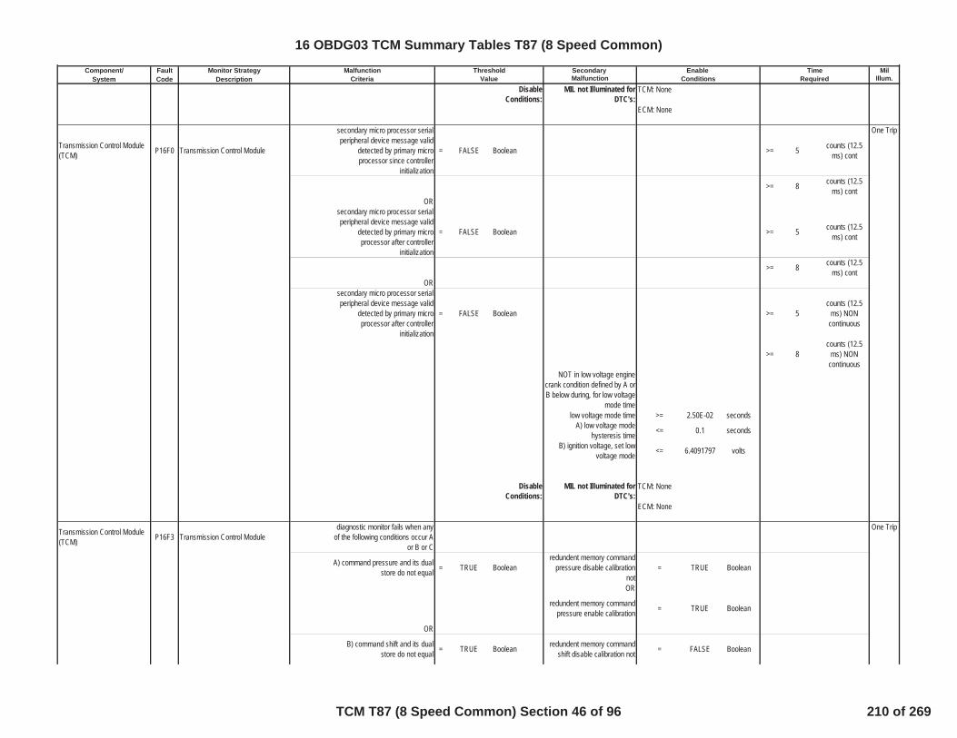
Component/ Fault Monitor Strategy Secondary MilSystem Code Description Malfunction Illum.
Malfunction Threshold Enable TimeCriteria Value Conditions Required
DisableConditions:
MIL not Illuminated forDTC's:
Transmission Control Module(TCM) P16F0 Transmission Control Module
secondary micro processor serialperipheral device message valid
detected by primary microprocessor since controller
initialization
= FALSE Boolean >= 5 counts (12.5ms) cont
One Trip
>= 8 counts (12.5ms) cont
ORsecondary micro processor serialperipheral device message valid
detected by primary microprocessor after controller
initialization
= FALSE Boolean >= 5 counts (12.5ms) cont
>= 8 counts (12.5ms) cont
ORsecondary micro processor serialperipheral device message valid
detected by primary microprocessor after controller
initialization
= FALSE Boolean >= 5counts (12.5
ms) NONcontinuous
>= 8counts (12.5
ms) NONcontinuous
NOT in low voltage enginecrank condition defined by A orB below during, for low voltage
mode timelow voltage mode time >= 2.50E-02 seconds
A) low voltage modehysteresis time <= 0.1 seconds
B) ignition voltage, set lowvoltage mode <= 6.4091797 volts
DisableConditions:
MIL not Illuminated forDTC's:
Transmission Control Module(TCM) P16F3 Transmission Control Module
diagnostic monitor fails when anyof the following conditions occur A
or B or C
One Trip
A) command pressure and its dualstore do not equal = TRUE Boolean
redundent memory commandpressure disable calibration
not= TRUE Boolean
OR
redundent memory commandpressure enable calibration = TRUE Boolean
OR
B) command shift and its dualstore do not equal = TRUE Boolean redundent memory command
shift disable calibration not = FALSE Boolean
TCM: None
ECM: None
TCM: None
ECM: None
16 OBDG03 TCM Summary Tables T87 (8 Speed Common)
TCM T87 (8 Speed Common) Section 46 of 96 210 of 269

Component/ Fault Monitor Strategy Secondary MilSystem Code Description Malfunction Illum.
Malfunction Threshold Enable TimeCriteria Value Conditions Required
OR Boolean
redundent memory commandshift enable calibration = TRUE Boolean
OR
C) rate limited vehicle speed andits dual store do not equal = TRUE Boolean rate limited vehicle speed dual
store enable calibration = TRUE Boolean >= 10counts (25
mseccontinuous)
>= 20counts (25
mseccontinuous)
DisableConditions:
MIL not Illuminated forDTC's:
Transmission Control Module(TCM) P16F4 Transmission Control Module
redundent path calculation ofdriver selected transmission range
error= TRUE Boolean >= 6
counts (25msec
continuous)
One Trip
>= 8counts (25
mseccontinuous)
secureed controller oremission critical ignition
voltage>= 11 volts
P16F4 status is not = test passthis key on Boolean
DisableConditions:
MIL not Illuminated forDTC's:
Transmission Control Module(TCM) P16FB Transmission Control Module
transmission output speed raw (25ms loop value) - transmission
output speed raw (6.25 ms loopvalue)
>= 60 RPM >= 8 seconds
One Trip
>= 10 secondsService Fast Learn (SFL)
Mode VBS Failsafe = FALSE Boolean
Battery Voltage Max (disabledabove this value) <= 31.999023 Volts
Battery Voltage Min (disabledbelow this value) <= 10 Volts
Ignition Voltage Min (disabledbelow this value) >= 10 Volts
for voltage stablity time >= 5 secondstransmission output speed raw
(6.25 ms loop value) >= 150 RPM
transmission output speed raw(25 ms loop value) >= 150 RPM
Service mode $04 active andend of trip pocessing active = FALSE Boolean
diagnostic monitor enablecalibration = 1 Boolean
TCM: None
ECM: None
TCM: None
ECM: None
16 OBDG03 TCM Summary Tables T87 (8 Speed Common)
TCM T87 (8 Speed Common) Section 47 of 96 211 of 269

Component/ Fault Monitor Strategy Secondary MilSystem Code Description Malfunction Illum.
Malfunction Threshold Enable TimeCriteria Value Conditions Required
DisableConditions:
MIL not Illuminated forDTC's:
Lateral acceleration signal P175F Lateral acceleration signal circuit(rolling count or checksum)
P175F will fail when A: messagealive rolling count erroror or B:
message checksum error
SpecialNo MIL
A: Rolling count value receivedfrom EBCM and expected TCM
calculated value not= TRUE Boolean >= 9
Fail Counter (50msec
continuous)
> 54 Fail Timer (Sec)
Lateral acceleration messagehealth (message receive
occur)= TRUE Boolean
Lateral acceleration signalcircuit rolling count diagnostic
monitor enable calibration= 1 Boolean
battery voltage <= 31.999023 voltsbattery voltage >= 9 volts
battery voltage time >= 0.1 secIgnition Voltage <= 31.999023 VoltsIgnition Voltage >= 9 Volts
Service Fast Learn (SFL)Mode VBS Failsafe = FALSE Boolean
Ignition voltage and SFLconditions met for >= 0.1 Sec
B: checksum of lateralacceleration message value error = TRUE Boolean >= 54 Fail Timer (Sec)
Lateral acceleration messagehealth (message receive
occur)= TRUE Boolean
Lateral acceleration signalcircuit checksum diagnostic
monitor enable calibration= 1 Boolean
battery voltage <= 31.999023 voltsbattery voltage >= 9 volts
battery voltage time >= 0.1 secIgnition Voltage <= 31.999023 VoltsIgnition Voltage >= 9 Volts
Service Fast Learn (SFL)Mode VBS Failsafe = FALSE Boolean
Ignition voltage and SFLconditions met for >= 0.1 Sec
normal serial datacommunication enabled = TRUE Boolean
DisableConditions:
MIL not Illuminated forDTC's:
Tap Up Tap Down Switch(TUTD) P1761 Tap Up and Down switch signal
circuit (rolling count)
Rolling count value received fromBCM and expected TCM
calculated value not= TRUE Boolean >= 3
Fail Counter(100 mseccontinuous)
SpecialNo MIL
TCM: None
ECM: None
TCM: U0073
ECM: None
16 OBDG03 TCM Summary Tables T87 (8 Speed Common)
TCM T87 (8 Speed Common) Section 48 of 96 212 of 269
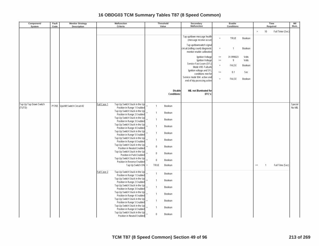
Component/ Fault Monitor Strategy Secondary MilSystem Code Description Malfunction Illum.
Malfunction Threshold Enable TimeCriteria Value Conditions Required
> 10 Fail Timer (Sec)
Tap up/down message health(message receive occur) = TRUE Boolean
Tap up/downswitch signalcircuit (rolling count) diagnostic
monitor enable calibration= 1 Boolean
Ignition Voltage <= 31.999023 VoltsIgnition Voltage >= 9 Volts
Service Fast Learn (SFL)Mode VBS Failsafe = FALSE Boolean
Ignition voltage and SFLconditions met for >= 0.1 Sec
Service mode $04 active andend of trip pocessing active = FALSE Boolean
DisableConditions:
MIL not Illuminated forDTC's:
Tap Up Tap Down Switch(TUTD) P1765 Upshift Switch Circuit #2 Fail Case 1 Tap Up Switch Stuck in the Up
Position in Range 1 Enabled = 1 Boolean SpecialNo MIL
Tap Up Switch Stuck in the UpPosition in Range 2 Enabled = 1 Boolean
Tap Up Switch Stuck in the UpPosition in Range 3 Enabled = 1 Boolean
Tap Up Switch Stuck in the UpPosition in Range 4 Enabled = 1 Boolean
Tap Up Switch Stuck in the UpPosition in Range 5 Enabled = 1 Boolean
Tap Up Switch Stuck in the UpPosition in Range 6 Enabled = 1 Boolean
Tap Up Switch Stuck in the UpPosition in Neutral Enabled = 0 Boolean
Tap Up Switch Stuck in the UpPosition in Park Enabled = 0 Boolean
Tap Up Switch Stuck in the UpPosition in Reverse Enabled = 0 Boolean
Tap Up Switch ON = TRUE Boolean >= 1 Fail Time (Sec)
Fail Case 2 Tap Up Switch Stuck in the UpPosition in Range 1 Enabled = 1 Boolean
Tap Up Switch Stuck in the UpPosition in Range 2 Enabled = 1 Boolean
Tap Up Switch Stuck in the UpPosition in Range 3 Enabled = 1 Boolean
Tap Up Switch Stuck in the UpPosition in Range 4 Enabled = 1 Boolean
Tap Up Switch Stuck in the UpPosition in Range 5 Enabled = 1 Boolean
Tap Up Switch Stuck in the UpPosition in Range 6 Enabled = 1 Boolean
Tap Up Switch Stuck in the UpPosition in Neutral Enabled = 0 Boolean
16 OBDG03 TCM Summary Tables T87 (8 Speed Common)
TCM T87 (8 Speed Common) Section 49 of 96 213 of 269

Component/ Fault Monitor Strategy Secondary MilSystem Code Description Malfunction Illum.
Malfunction Threshold Enable TimeCriteria Value Conditions Required
Tap Up Switch Stuck in the UpPosition in Park Enabled = 0 Boolean
Tap Up Switch Stuck in the UpPosition in Reverse Enabled = 0 Boolean
Tap Up Switch ON = TRUE BooleanNOTE: Both Failcase1 and
Failcase 2 Must Be Met >= 120 Fail Time (Sec)
Time Since Last RangeChange >= 1 Enable Time
(Sec)Ignition Voltage Lo >= 9 VoltsIgnition Voltage Hi <= 31.999023 VoltsEngine Speed Lo >= 250 RPMEngine Speed Hi <= 7500 RPM
Engine Speed is within theallowable limits for >= 5 Sec
P1765 Status is
Test FailedThis Key
On orFaultActive
DisableConditions:
MIL not Illuminated forDTC's:
Tap Up Tap Down Switch(TUTD) P1766 Downshift Switch Circuit #2
Fail Case 1 Tap Down Switch Stuck in theDown Position in Range 1 Enabled = 1 Boolean
SpecialNo MIL
Tap Down Switch Stuck in theDown Position in Range 2 Enabled = 1 Boolean
Tap Down Switch Stuck in theDown Position in Range 3 Enabled = 1 Boolean
Tap Down Switch Stuck in theDown Position in Range 4 Enabled = 1 Boolean
Tap Down Switch Stuck in theDown Position in Range 5 Enabled = 1 Boolean
Tap Down Switch Stuck in theDown Position in Range 6 Enabled = 1 Boolean
Tap Down Switch Stuck in theDown Position in Range Neutral
Enabled= 0 Boolean
Tap Down Switch Stuck in theDown Position in Range Park
Enabled= 0 Boolean
Tap Down Switch Stuck in theDown Position in Range Reverse
Enabled= 0 Boolean
Tap Down Switch ON = TRUE Boolean >= 1 sec
TCM: P1767, P1761, P182E, P1915
ECM: None
16 OBDG03 TCM Summary Tables T87 (8 Speed Common)
TCM T87 (8 Speed Common) Section 50 of 96 214 of 269
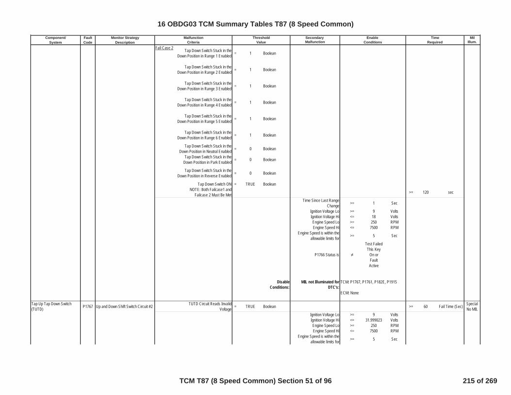
Component/ Fault Monitor Strategy Secondary MilSystem Code Description Malfunction Illum.
Malfunction Threshold Enable TimeCriteria Value Conditions Required
Fail Case 2 Tap Down Switch Stuck in theDown Position in Range 1 Enabled = 1 Boolean
Tap Down Switch Stuck in theDown Position in Range 2 Enabled = 1 Boolean
Tap Down Switch Stuck in theDown Position in Range 3 Enabled = 1 Boolean
Tap Down Switch Stuck in theDown Position in Range 4 Enabled = 1 Boolean
Tap Down Switch Stuck in theDown Position in Range 5 Enabled = 1 Boolean
Tap Down Switch Stuck in theDown Position in Range 6 Enabled = 1 Boolean
Tap Down Switch Stuck in theDown Position in Neutral Enabled = 0 Boolean
Tap Down Switch Stuck in theDown Position in Park Enabled = 0 Boolean
Tap Down Switch Stuck in theDown Position in Reverse Enabled = 0 Boolean
Tap Down Switch ON = TRUE BooleanNOTE: Both Failcase1 and
Failcase 2 Must Be Met >= 120 sec
Time Since Last RangeChange >= 1 Sec
Ignition Voltage Lo >= 9 VoltsIgnition Voltage Hi <= 18 VoltsEngine Speed Lo >= 250 RPMEngine Speed Hi <= 7500 RPM
Engine Speed is within theallowable limits for >= 5 Sec
P1766 Status is
Test FailedThis Key
On orFaultActive
DisableConditions:
MIL not Illuminated forDTC's:
Tap Up Tap Down Switch(TUTD) P1767 Up and Down Shift Switch Circuit #2 TUTD Circuit Reads Invalid
Voltage = TRUE Boolean >= 60 Fail Time (Sec) SpecialNo MIL
Ignition Voltage Lo >= 9 VoltsIgnition Voltage Hi <= 31.999023 VoltsEngine Speed Lo >= 250 RPMEngine Speed Hi <= 7500 RPM
Engine Speed is within theallowable limits for >= 5 Sec
TCM: P1767, P1761, P182E, P1915
ECM: None
16 OBDG03 TCM Summary Tables T87 (8 Speed Common)
TCM T87 (8 Speed Common) Section 51 of 96 215 of 269
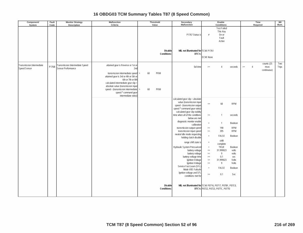
Component/ Fault Monitor Strategy Secondary MilSystem Code Description Malfunction Illum.
Malfunction Threshold Enable TimeCriteria Value Conditions Required
P1767 Status is
Test FailedThis Key
On orFaultActive
DisableConditions:
MIL not Illuminated forDTC's:
Transmission IntermediateSpeed Sensor P176B Transmission Intermediate Speed
Sensor Performanceattained gear is Reverse or 1st or
2nd fail time >= 4 seconds >= 4counts (25
mseccontinuous)
TwoTrips
transmssion intermediate speed > 60 PRMattained gear is 3rd or 4th or 5th or
6th or 7th or 8thcalculated intermediate gear slip =absolute value (transmission inputspeed - (transmission intermediate
speed * command gearintermediate ratio))
> 60 PRM
calculated gear slip = absolutevalue (transmission input
speed - (transmission outputspeed * command gear ratio))
<= 60 RPM
calculated gear slip stablitytime when all of the conditions
below are met>= 1 seconds
diagnostic monitor enablecalibration = 1 Boolean
transmission output speed >= 190 RPMtransmission input speed >= 395 RPM
neutral idle mode requestingholding clutch disable = FALSE Boolean
range shift state is = shiftcomplete
Hydraulic System Pressurized = TRUE Booleanbattery voltage <= 31.999023 voltsbattery voltage >= 9 volts
battery voltage time >= 0.1 secIgnition Voltage <= 31.999023 VoltsIgnition Voltage >= 9 Volts
Service Fast Learn (SFL)Mode VBS Failsafe = FALSE Boolean
Ignition voltage and SFLconditions met for >= 0.1 Sec
DisableConditions:
MIL not Illuminated forDTC's:
TCM: P1761
ECM: None
TCM: P0716, P0717, P07BF, P07C0,P0722, P0723, P077C, P077D
16 OBDG03 TCM Summary Tables T87 (8 Speed Common)
TCM T87 (8 Speed Common) Section 52 of 96 216 of 269

Component/ Fault Monitor Strategy Secondary MilSystem Code Description Malfunction Illum.
Malfunction Threshold Enable TimeCriteria Value Conditions Required
Transmission IntermediateSpeed Sensor P176C Intermediate Speed Sensor Circuit
Low speed sensor1 voltage <=see Table 51in supportingdocuments
volts speed sensor1 fail time >=
see Table53 in
supportingdocuments
seconds >=see Table 52in supportingdocuments
counts (12.5msec
continuous)
TwoTrips
speed sensor1 circuit lowdiagnostic monitor enable
calibration=
see Table54 in
supportingdocuments
Boolean
Service mode $04 active andend of trip pocessing active = FALSE Boolean
Service Fast Learn (SFL)Mode VBS Failsafe = FALSE Boolean
Battery Voltage Max (disabledabove this value) <= 31.999023 Volts
Battery Voltage Min (disabledbelow this value) <= 10 Volts
Ignition Voltage Min (disabledbelow this value) >= 10 Volts
for voltage stablity time >= 5 seconds
P176C Status is not =
Test FailedThis Key
On orFaultActive
DisableConditions:
MIL not Illuminated forDTC's:
Transmission IntermediateSpeed Sensor P176D Intermediate Speed Sensor Circuit
High speed sensor1 voltage >=see Table 55in supportingdocuments
volts speed sensor1 fail time >=
see Table57 in
supportingdocuments
seconds >=see Table 56in supportingdocuments
counts (12.5msec
continuous)
TwoTrips
speed sensor1 circuit highdiagnostic monitor enable
calibration=
see Table58 in
supportingdocuments
Boolean
Service mode $04 active andend of trip pocessing active = FALSE Boolean
Service Fast Learn (SFL)Mode VBS Failsafe = FALSE Boolean
Battery Voltage Max (disabledabove this value) <= 31.999023 Volts
Battery Voltage Min (disabledbelow this value) <= 10 Volts
Ignition Voltage Min (disabledbelow this value) >= 10 Volts
for voltage stablity time >= 5 seconds
TCM: P176D
16 OBDG03 TCM Summary Tables T87 (8 Speed Common)
TCM T87 (8 Speed Common) Section 53 of 96 217 of 269

Component/ Fault Monitor Strategy Secondary MilSystem Code Description Malfunction Illum.
Malfunction Threshold Enable TimeCriteria Value Conditions Required
P176D Status is not =
Test FailedThis Key
On orFaultActive
DisableConditions:
MIL not Illuminated forDTC's:
Internal Mode Switch (IMS) P1824 Internal Mode Switch P Circuit HighVoltage IMS switch P voltage > 2.380000114 volts >= 70 Fail Counts
(25ms loop)TwoTrips
outof 80 Sample Counts
(25ms loop)Diagnostic monitor enable
calibration = 1 Boolean
Ignition Voltage Lo >= 9 VoltsIgnition Voltage Hi <= 31.999023 Volts
If ignition voltage waspreviously between the abovelow / high thresholds, then the
following conditions apply onceper auto start event
Ignition Voltage Lo >= 7 VoltsIgnition Voltage Hi < 9 Volts
Ignition Voltage within theabove low / high thresholds for <= 7.50E-02 seconds
DisableConditions:
MIL not Illuminated forDTC's:
Internal Mode Switch (IMS) P182A Internal Mode Switch A Circuit LowVoltage IMS switch A voltage < 0.699999988 volts >= 70 Fail Counts
(25ms loop)TwoTrips
outof 80 Sample Counts
(25ms loop)Diagnostic monitor enable
calibration = 1 Boolean
Ignition Voltage Lo >= 9 VoltsIgnition Voltage Hi <= 31.999023 Volts
If ignition voltage waspreviously between the abovelow / high thresholds, then the
following conditions apply onceper auto start event
Ignition Voltage Lo >= 7 VoltsIgnition Voltage Hi < 9 Volts
Ignition Voltage within theabove low / high thresholds for <= 7.50E-02 seconds
TCM: None
ECM: None
TCM: P176C
16 OBDG03 TCM Summary Tables T87 (8 Speed Common)
TCM T87 (8 Speed Common) Section 54 of 96 218 of 269
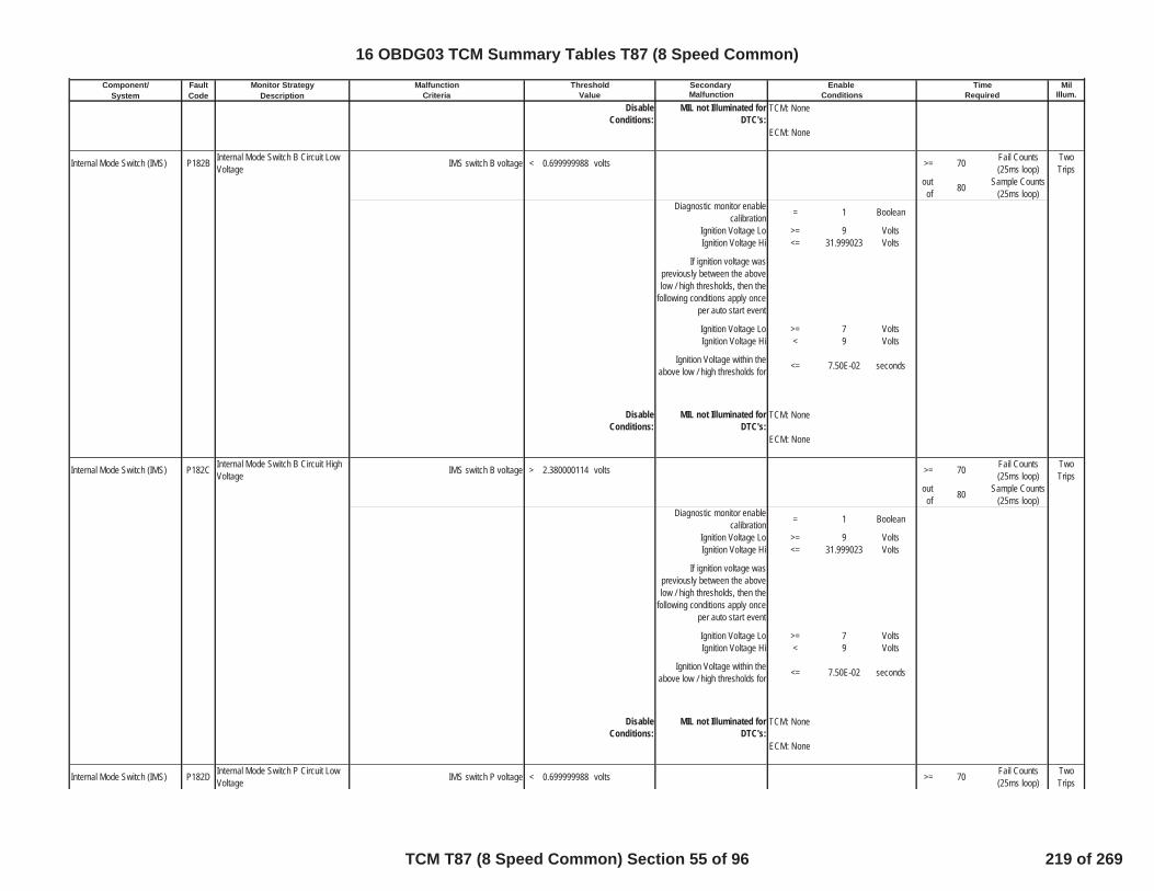
Component/ Fault Monitor Strategy Secondary MilSystem Code Description Malfunction Illum.
Malfunction Threshold Enable TimeCriteria Value Conditions Required
DisableConditions:
MIL not Illuminated forDTC's:
Internal Mode Switch (IMS) P182B Internal Mode Switch B Circuit LowVoltage IMS switch B voltage < 0.699999988 volts >= 70 Fail Counts
(25ms loop)TwoTrips
outof 80 Sample Counts
(25ms loop)Diagnostic monitor enable
calibration = 1 Boolean
Ignition Voltage Lo >= 9 VoltsIgnition Voltage Hi <= 31.999023 Volts
If ignition voltage waspreviously between the abovelow / high thresholds, then the
following conditions apply onceper auto start event
Ignition Voltage Lo >= 7 VoltsIgnition Voltage Hi < 9 Volts
Ignition Voltage within theabove low / high thresholds for <= 7.50E-02 seconds
DisableConditions:
MIL not Illuminated forDTC's:
Internal Mode Switch (IMS) P182C Internal Mode Switch B Circuit HighVoltage IMS switch B voltage > 2.380000114 volts >= 70 Fail Counts
(25ms loop)TwoTrips
outof 80 Sample Counts
(25ms loop)Diagnostic monitor enable
calibration = 1 Boolean
Ignition Voltage Lo >= 9 VoltsIgnition Voltage Hi <= 31.999023 Volts
If ignition voltage waspreviously between the abovelow / high thresholds, then the
following conditions apply onceper auto start event
Ignition Voltage Lo >= 7 VoltsIgnition Voltage Hi < 9 Volts
Ignition Voltage within theabove low / high thresholds for <= 7.50E-02 seconds
DisableConditions:
MIL not Illuminated forDTC's:
Internal Mode Switch (IMS) P182D Internal Mode Switch P Circuit LowVoltage IMS switch P voltage < 0.699999988 volts >= 70 Fail Counts
(25ms loop)TwoTrips
TCM: None
ECM: None
TCM: None
ECM: None
TCM: None
ECM: None
16 OBDG03 TCM Summary Tables T87 (8 Speed Common)
TCM T87 (8 Speed Common) Section 55 of 96 219 of 269

Component/ Fault Monitor Strategy Secondary MilSystem Code Description Malfunction Illum.
Malfunction Threshold Enable TimeCriteria Value Conditions Required
outof 80 Sample Counts
(25ms loop)Diagnostic monitor enable
calibration = 1 Boolean
Ignition Voltage Lo >= 9 VoltsIgnition Voltage Hi <= 31.999023 Volts
If ignition voltage waspreviously between the abovelow / high thresholds, then the
following conditions apply onceper auto start event
Ignition Voltage Lo >= 7 VoltsIgnition Voltage Hi < 9 Volts
Ignition Voltage within theabove low / high thresholds for <= 7.50E-02 seconds
DisableConditions:
MIL not Illuminated forDTC's:
Internal Mode Switch (IMS) P182E Internal Mode Switch Illegal Range Range =
Illegal(SABCP=
00000or
SABCP=10000)
enumeration >= 108 Fail Counts(25ms loop)
TwoTrips
outof 125 Sample Counts
(25ms loop)Diagnostic monitor enable
calibration = 1 Boolean
Ignition Voltage Lo >= 9 VoltsIgnition Voltage Hi <= 31.999023 Volts
If ignition voltage waspreviously between the abovelow / high thresholds, then the
following conditions apply onceper auto start event
Ignition Voltage Lo >= 7 VoltsIgnition Voltage Hi < 9 Volts
Ignition Voltage within theabove low / high thresholds for <= 7.50E-02 seconds
DisableConditions:
MIL not Illuminated forDTC's:
Internal Mode Switch (IMS) P182F Internal Mode Switch C Circuit HighVoltage IMS switch C voltage > 2.380000114 volts >= 70 Fail Counts
(25ms loop)TwoTrips
outof 80 Sample Counts
(25ms loop)
TCM: None
ECM: None
TCM: None
ECM: None
16 OBDG03 TCM Summary Tables T87 (8 Speed Common)
TCM T87 (8 Speed Common) Section 56 of 96 220 of 269

Component/ Fault Monitor Strategy Secondary MilSystem Code Description Malfunction Illum.
Malfunction Threshold Enable TimeCriteria Value Conditions Required
Diagnostic monitor enablecalibration = 1 Boolean
Ignition Voltage Lo >= 9 VoltsIgnition Voltage Hi <= 31.999023 Volts
If ignition voltage waspreviously between the abovelow / high thresholds, then the
following conditions apply onceper auto start event
Ignition Voltage Lo >= 7 VoltsIgnition Voltage Hi < 9 Volts
Ignition Voltage within theabove low / high thresholds for <= 7.50E-02 seconds
DisableConditions:
MIL not Illuminated forDTC's:
Internal Mode Switch (IMS) P1838 Internal Mode Switch A Circuit HighVoltage IMS switch A voltage > 2.380000114 volts >= 70 Fail Counts
(25ms loop)TwoTrips
outof 80 Sample Counts
(25ms loop)Diagnostic monitor enable
calibration = 1 Boolean
Ignition Voltage Lo >= 9 VoltsIgnition Voltage Hi <= 31.999023 Volts
If ignition voltage waspreviously between the abovelow / high thresholds, then the
following conditions apply onceper auto start event
Ignition Voltage Lo >= 7 VoltsIgnition Voltage Hi < 9 Volts
Ignition Voltage within theabove low / high thresholds for <= 7.50E-02 seconds
DisableConditions:
MIL not Illuminated forDTC's:
Internal Mode Switch (IMS) P1839 Internal Mode Switch C Circuit LowVoltage IMS switch C voltage < 0.699999988 volts >= 70 Fail Counts
(25ms loop)TwoTrips
outof 80 Sample Counts
(25ms loop)Diagnostic monitor enable
calibration = 1 Boolean
Ignition Voltage Lo >= 9 VoltsIgnition Voltage Hi <= 31.999023 Volts
TCM: None
ECM: None
TCM: None
ECM: None
16 OBDG03 TCM Summary Tables T87 (8 Speed Common)
TCM T87 (8 Speed Common) Section 57 of 96 221 of 269

Component/ Fault Monitor Strategy Secondary MilSystem Code Description Malfunction Illum.
Malfunction Threshold Enable TimeCriteria Value Conditions Required
If ignition voltage waspreviously between the abovelow / high thresholds, then the
following conditions apply onceper auto start event
Ignition Voltage Lo >= 7 VoltsIgnition Voltage Hi < 9 Volts
Ignition Voltage within theabove low / high thresholds for <= 7.50E-02 seconds
DisableConditions:
MIL not Illuminated forDTC's:
Internal Mode Switch (IMS) P1840 Internal Mode Switch S Circuit LowVoltage IMS switch S voltage < 0.699999988 volts >= 70 Fail Counts
(25ms loop)TwoTrips
outof 80 Sample Counts
(25ms loop)Diagnostic monitor enable
calibration = 1 Boolean
Ignition Voltage Lo >= 9 VoltsIgnition Voltage Hi <= 31.999023 Volts
If ignition voltage waspreviously between the abovelow / high thresholds, then the
following conditions apply onceper auto start event
Ignition Voltage Lo >= 7 VoltsIgnition Voltage Hi < 9 Volts
Ignition Voltage within theabove low / high thresholds for <= 7.50E-02 seconds
DisableConditions:
MIL not Illuminated forDTC's:
Internal Mode Switch (IMS) P1841 Internal Mode Switch S Circuit HighVoltage IMS switch S voltage > 2.380000114 volts >= 70 Fail Counts
(25ms loop)TwoTrips
outof 80 Sample Counts
(25ms loop)Diagnostic monitor enable
calibration = 1 Boolean
Ignition Voltage Lo >= 9 VoltsIgnition Voltage Hi <= 31.999023 Volts
If ignition voltage waspreviously between the abovelow / high thresholds, then the
following conditions apply onceper auto start event
Ignition Voltage Lo >= 7 Volts
TCM: None
ECM: None
TCM: None
ECM: None
16 OBDG03 TCM Summary Tables T87 (8 Speed Common)
TCM T87 (8 Speed Common) Section 58 of 96 222 of 269
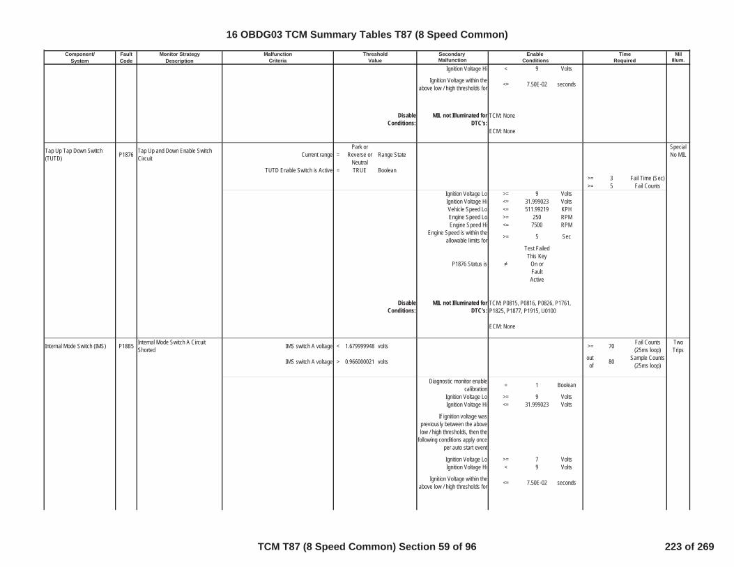
Component/ Fault Monitor Strategy Secondary MilSystem Code Description Malfunction Illum.
Malfunction Threshold Enable TimeCriteria Value Conditions Required
Ignition Voltage Hi < 9 Volts
Ignition Voltage within theabove low / high thresholds for <= 7.50E-02 seconds
DisableConditions:
MIL not Illuminated forDTC's:
Tap Up Tap Down Switch(TUTD) P1876 Tap Up and Down Enable Switch
Circuit Current range =Park or
Reverse orNeutral
Range StateSpecialNo MIL
TUTD Enable Switch is Active = TRUE Boolean>= 3 Fail Time (Sec)>= 5 Fail Counts
Ignition Voltage Lo >= 9 VoltsIgnition Voltage Hi <= 31.999023 VoltsVehicle Speed Lo <= 511.99219 KPHEngine Speed Lo >= 250 RPMEngine Speed Hi <= 7500 RPM
Engine Speed is within theallowable limits for >= 5 Sec
P1876 Status is
Test FailedThis Key
On orFaultActive
DisableConditions:
MIL not Illuminated forDTC's:
Internal Mode Switch (IMS) P18B5 Internal Mode Switch A CircuitShorted IMS switch A voltage < 1.679999948 volts >= 70 Fail Counts
(25ms loop)TwoTrips
IMS switch A voltage > 0.966000021 volts outof 80 Sample Counts
(25ms loop)
Diagnostic monitor enablecalibration = 1 Boolean
Ignition Voltage Lo >= 9 VoltsIgnition Voltage Hi <= 31.999023 Volts
If ignition voltage waspreviously between the abovelow / high thresholds, then the
following conditions apply onceper auto start event
Ignition Voltage Lo >= 7 VoltsIgnition Voltage Hi < 9 Volts
Ignition Voltage within theabove low / high thresholds for <= 7.50E-02 seconds
TCM: None
ECM: None
TCM: P0815, P0816, P0826, P1761,P1825, P1877, P1915, U0100
ECM: None
16 OBDG03 TCM Summary Tables T87 (8 Speed Common)
TCM T87 (8 Speed Common) Section 59 of 96 223 of 269

Component/ Fault Monitor Strategy Secondary MilSystem Code Description Malfunction Illum.
Malfunction Threshold Enable TimeCriteria Value Conditions Required
DisableConditions:
MIL not Illuminated forDTC's:
Internal Mode Switch (IMS) P18B6 Internal Mode Switch B CircuitShorted IMS switch B voltage < 1.679999948 volts >= 70 Fail Counts
(25ms loop)TwoTrips
IMS switch B voltage > 0.966000021 volts outof 80 Sample Counts
(25ms loop)
Diagnostic monitor enablecalibration = 1 Boolean
Ignition Voltage Lo >= 9 VoltsIgnition Voltage Hi <= 31.999023 Volts
If ignition voltage waspreviously between the abovelow / high thresholds, then the
following conditions apply onceper auto start event
Ignition Voltage Lo >= 7 VoltsIgnition Voltage Hi < 9 Volts
Ignition Voltage within theabove low / high thresholds for <= 7.50E-02 seconds
DisableConditions:
MIL not Illuminated forDTC's:
Internal Mode Switch (IMS) P18B7 Internal Mode Switch C CircuitShorted IMS switch C voltage < 1.679999948 volts >= 70 Fail Counts
(25ms loop)TwoTrips
IMS switch C voltage > 0.966000021 volts outof 80 Sample Counts
(25ms loop)
Diagnostic monitor enablecalibration = 1 Boolean
Ignition Voltage Lo >= 9 VoltsIgnition Voltage Hi <= 31.999023 Volts
If ignition voltage waspreviously between the abovelow / high thresholds, then the
following conditions apply onceper auto start event
Ignition Voltage Lo >= 7 VoltsIgnition Voltage Hi < 9 Volts
Ignition Voltage within theabove low / high thresholds for <= 7.50E-02 seconds
DisableConditions:
MIL not Illuminated forDTC's:
TCM: None
ECM: None
TCM: None
ECM: None
TCM: None
ECM: None
16 OBDG03 TCM Summary Tables T87 (8 Speed Common)
TCM T87 (8 Speed Common) Section 60 of 96 224 of 269

Component/ Fault Monitor Strategy Secondary MilSystem Code Description Malfunction Illum.
Malfunction Threshold Enable TimeCriteria Value Conditions Required
Internal Mode Switch (IMS) P18B8 Internal Mode Switch P CircuitShorted IMS switch P voltage < 1.679999948 volts >= 70 Fail Counts
(25ms loop)TwoTrips
IMS switch P voltage > 0.966000021 volts outof 80 Sample Counts
(25ms loop)
Diagnostic monitor enablecalibration = 1 Boolean
Ignition Voltage Lo >= 9 VoltsIgnition Voltage Hi <= 31.999023 Volts
If ignition voltage waspreviously between the abovelow / high thresholds, then the
following conditions apply onceper auto start event
Ignition Voltage Lo >= 7 VoltsIgnition Voltage Hi < 9 Volts
Ignition Voltage within theabove low / high thresholds for <= 7.50E-02 seconds
DisableConditions:
MIL not Illuminated forDTC's:
Internal Mode Switch (IMS) P18B9 Internal Mode Switch S CircuitShorted IMS switch S voltage < 1.679999948 volts >= 70 Fail Counts
(25ms loop)TwoTrips
IMS switch S voltage > 0.966000021 volts outof 80 Sample Counts
(25ms loop)
Diagnostic monitor enablecalibration = 1 Boolean
Ignition Voltage Lo >= 9 VoltsIgnition Voltage Hi <= 31.999023 Volts
If ignition voltage waspreviously between the abovelow / high thresholds, then the
following conditions apply onceper auto start event
Ignition Voltage Lo >= 7 VoltsIgnition Voltage Hi < 9 Volts
Ignition Voltage within theabove low / high thresholds for <= 7.50E-02 seconds
DisableConditions:
MIL not Illuminated forDTC's:
Internal Mode Switch (IMS) P18BA Internal Mode Switch A Stuck Off Range =Transition 30
(SABCP=00001)
enumeration >= 108 Fail Counts(25ms loop)
TwoTrips
Switch A True (this keycycle) boolean out
of 125 Sample Counts(25ms loop)
TCM: None
ECM: None
TCM: None
ECM: None
16 OBDG03 TCM Summary Tables T87 (8 Speed Common)
TCM T87 (8 Speed Common) Section 61 of 96 225 of 269

Component/ Fault Monitor Strategy Secondary MilSystem Code Description Malfunction Illum.
Malfunction Threshold Enable TimeCriteria Value Conditions Required
Diagnostic monitor enablecalibration = 1 Boolean
Ignition Voltage Lo >= 9 VoltsIgnition Voltage Hi <= 31.999023 Volts
If ignition voltage waspreviously between the abovelow / high thresholds, then the
following conditions apply onceper auto start event
Ignition Voltage Lo >= 7 VoltsIgnition Voltage Hi < 9 Volts
Ignition Voltage within theabove low / high thresholds for <= 7.50E-02 seconds
DisableConditions:
MIL not Illuminated forDTC's:
Internal Mode Switch (IMS) P18BB Internal Mode Switch B Stuck Off Range =Transition 29
(SABCP=00010)
enumeration >= 108 Fail Counts(25ms loop)
TwoTrips
Prev Range =Transition 14
(SABCP=10001)
outof 125 Sample Counts
(25ms loop)
Diagnostic monitor enablecalibration = 1 Boolean
Ignition Voltage Lo >= 9 VoltsIgnition Voltage Hi <= 31.999023 Volts
If ignition voltage waspreviously between the abovelow / high thresholds, then the
following conditions apply onceper auto start event
Ignition Voltage Lo >= 7 VoltsIgnition Voltage Hi < 9 Volts
Ignition Voltage within theabove low / high thresholds for <= 7.50E-02 seconds
DisableConditions:
MIL not Illuminated forDTC's:
Internal Mode Switch (IMS) P18BC Internal Mode Switch C Stuck Off Range =Transition 27
(SABCP=00100)
enumeration >= 108 Fail Counts(25ms loop)
TwoTrips
outof 125 Sample Counts
(25ms loop)
TCM: None
ECM: None
TCM: None
ECM: None
16 OBDG03 TCM Summary Tables T87 (8 Speed Common)
TCM T87 (8 Speed Common) Section 62 of 96 226 of 269
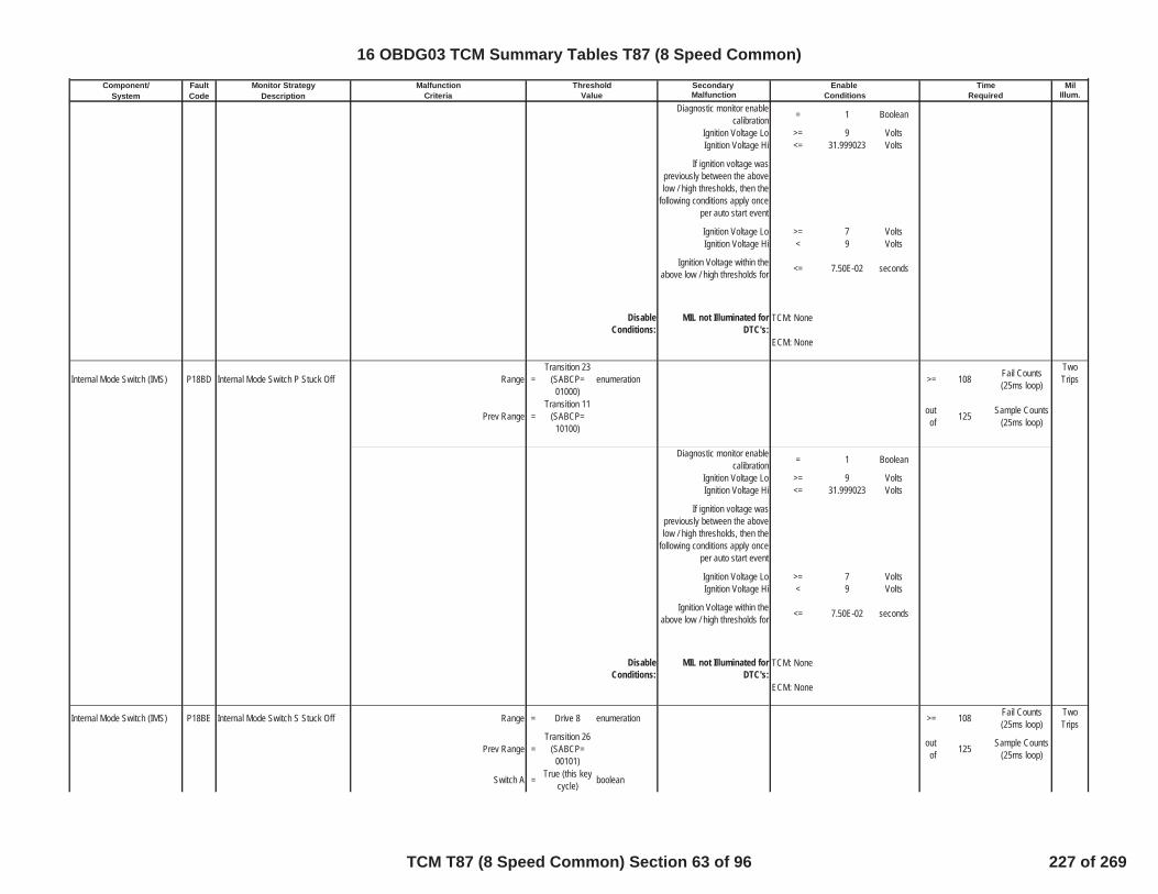
Component/ Fault Monitor Strategy Secondary MilSystem Code Description Malfunction Illum.
Malfunction Threshold Enable TimeCriteria Value Conditions Required
Diagnostic monitor enablecalibration = 1 Boolean
Ignition Voltage Lo >= 9 VoltsIgnition Voltage Hi <= 31.999023 Volts
If ignition voltage waspreviously between the abovelow / high thresholds, then the
following conditions apply onceper auto start event
Ignition Voltage Lo >= 7 VoltsIgnition Voltage Hi < 9 Volts
Ignition Voltage within theabove low / high thresholds for <= 7.50E-02 seconds
DisableConditions:
MIL not Illuminated forDTC's:
Internal Mode Switch (IMS) P18BD Internal Mode Switch P Stuck Off Range =Transition 23
(SABCP=01000)
enumeration >= 108 Fail Counts(25ms loop)
TwoTrips
Prev Range =Transition 11
(SABCP=10100)
outof 125 Sample Counts
(25ms loop)
Diagnostic monitor enablecalibration = 1 Boolean
Ignition Voltage Lo >= 9 VoltsIgnition Voltage Hi <= 31.999023 Volts
If ignition voltage waspreviously between the abovelow / high thresholds, then the
following conditions apply onceper auto start event
Ignition Voltage Lo >= 7 VoltsIgnition Voltage Hi < 9 Volts
Ignition Voltage within theabove low / high thresholds for <= 7.50E-02 seconds
DisableConditions:
MIL not Illuminated forDTC's:
Internal Mode Switch (IMS) P18BE Internal Mode Switch S Stuck Off Range = Drive 8 enumeration >= 108 Fail Counts(25ms loop)
TwoTrips
Prev Range =Transition 26
(SABCP=00101)
outof 125 Sample Counts
(25ms loop)
Switch A = True (this keycycle) boolean
TCM: None
ECM: None
TCM: None
ECM: None
16 OBDG03 TCM Summary Tables T87 (8 Speed Common)
TCM T87 (8 Speed Common) Section 63 of 96 227 of 269

Component/ Fault Monitor Strategy Secondary MilSystem Code Description Malfunction Illum.
Malfunction Threshold Enable TimeCriteria Value Conditions Required
Switch S True (this keycycle) boolean
Diagnostic monitor enablecalibration = 1 Boolean
Ignition Voltage Lo >= 9 VoltsIgnition Voltage Hi <= 31.999023 Volts
If ignition voltage waspreviously between the abovelow / high thresholds, then the
following conditions apply onceper auto start event
Ignition Voltage Lo >= 7 VoltsIgnition Voltage Hi < 9 Volts
Ignition Voltage within theabove low / high thresholds for <= 7.50E-02 seconds
DisableConditions:
MIL not Illuminated forDTC's:
Internal Mode Switch (IMS) P18C0 Internal Mode Switch B Stuck On Range = Drive 8 enumeration >= 108 Fail Counts(25ms loop)
TwoTrips
Prev Range = Park for >= 80 counts (25msloop)
outof 125 Sample Counts
(25ms loop)
Switch B False (thiskey cycle) boolean
Diagnostic monitor enablecalibration = 1 Boolean
Ignition Voltage Lo >= 9 VoltsIgnition Voltage Hi <= 31.999023 Volts
If ignition voltage waspreviously between the abovelow / high thresholds, then the
following conditions apply onceper auto start event
Ignition Voltage Lo >= 7 VoltsIgnition Voltage Hi < 9 Volts
Ignition Voltage within theabove low / high thresholds for <= 7.50E-02 seconds
DisableConditions:
MIL not Illuminated forDTC's:
Internal Mode Switch (IMS) P18C1 Internal Mode Switch C Stuck On Range =Transition 20
(SABCP=01011)
enumeration >= 108 Fail Counts(25ms loop)
TwoTrips
Switch C False (thiskey cycle) boolean out
of 125 Sample Counts(25ms loop)
TCM: None
ECM: None
TCM: None
ECM: None
16 OBDG03 TCM Summary Tables T87 (8 Speed Common)
TCM T87 (8 Speed Common) Section 64 of 96 228 of 269

Component/ Fault Monitor Strategy Secondary MilSystem Code Description Malfunction Illum.
Malfunction Threshold Enable TimeCriteria Value Conditions Required
Diagnostic monitor enablecalibration = 1 Boolean
Ignition Voltage Lo >= 9 VoltsIgnition Voltage Hi <= 31.999023 Volts
If ignition voltage waspreviously between the abovelow / high thresholds, then the
following conditions apply onceper auto start event
Ignition Voltage Lo >= 7 VoltsIgnition Voltage Hi < 9 Volts
Ignition Voltage within theabove low / high thresholds for <= 7.50E-02 seconds
DisableConditions:
MIL not Illuminated forDTC's:
Internal Mode Switch (IMS) P18C2 Internal Mode Switch P Stuck On Range =Transition 24
(SABCP=00111)
enumeration >= 108 Fail Counts(25ms loop)
TwoTrips
outof 125 Sample Counts
(25ms loop)
Diagnostic monitor enablecalibration = 1 Boolean
Ignition Voltage Lo >= 9 VoltsIgnition Voltage Hi <= 31.999023 Volts
If ignition voltage waspreviously between the abovelow / high thresholds, then the
following conditions apply onceper auto start event
Ignition Voltage Lo >= 7 VoltsIgnition Voltage Hi < 9 Volts
Ignition Voltage within theabove low / high thresholds for <= 7.50E-02 seconds
DisableConditions:
MIL not Illuminated forDTC's:
Internal Mode Switch (IMS) P18C3 Internal Mode Switch S Stuck On Range = Drive 7 enumeration >= 108 Fail Counts(25ms loop)
TwoTrips
Prev Range = Park for >= 80 counts (25msloop)
outof 125 Sample Counts
(25ms loop)
Switch S False (thiskey cycle) boolean
Diagnostic monitor enablecalibration = 1 Boolean
Ignition Voltage Lo >= 9 Volts
TCM: None
ECM: None
TCM: None
ECM: None
16 OBDG03 TCM Summary Tables T87 (8 Speed Common)
TCM T87 (8 Speed Common) Section 65 of 96 229 of 269
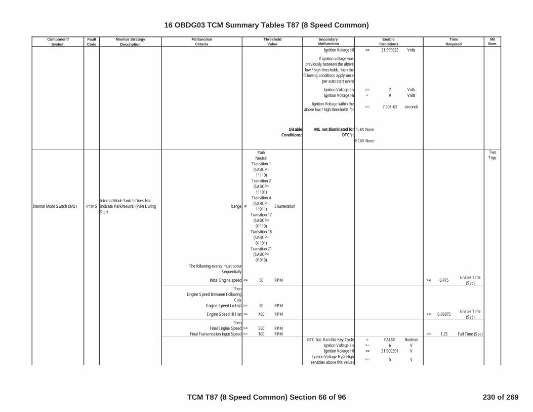
Component/ Fault Monitor Strategy Secondary MilSystem Code Description Malfunction Illum.
Malfunction Threshold Enable TimeCriteria Value Conditions Required
Ignition Voltage Hi <= 31.999023 Volts
If ignition voltage waspreviously between the abovelow / high thresholds, then the
following conditions apply onceper auto start event
Ignition Voltage Lo >= 7 VoltsIgnition Voltage Hi < 9 Volts
Ignition Voltage within theabove low / high thresholds for <= 7.50E-02 seconds
DisableConditions:
MIL not Illuminated forDTC's:
Internal Mode Switch (IMS) P1915Internal Mode Switch Does NotIndicate Park/Neutral (P/N) DuringStart
Range
ParkNeutral
Transition 1(SABCP=
11110)Transition 2(SABCP=
11101)Transition 4(SABCP=
11011)Transition 17
(SABCP=01110)
Transition 18(SABCP=
01101)Transition 21
(SABCP=01010)
Enumeration
TwoTrips
The following events must occurSequentially
Initial Engine speed <= 50 RPM >= 0.475 Enable Time(Sec)
ThenEngine Speed Between Following
CalsEngine Speed Lo Hist >= 50 RPM
Engine Speed Hi Hist <= 480 RPM >= 0.06875 Enable Time(Sec)
ThenFinal Engine Speed >= 550 RPM
Final Transmission Input Speed >= 100 RPM >= 1.25 Fail Time (Sec)DTC has Ran this Key Cycle = FALSE Boolean
Ignition Voltage Lo >= 6 VIgnition Voltage Hi <= 31.900391 V
Ignition Voltage Hyst High(enables above this value) >= 5 V
TCM: None
ECM: None
16 OBDG03 TCM Summary Tables T87 (8 Speed Common)
TCM T87 (8 Speed Common) Section 66 of 96 230 of 269
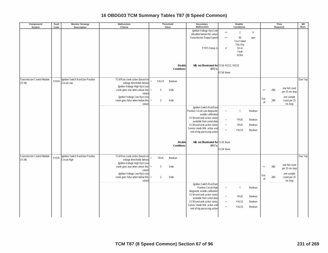
Component/ Fault Monitor Strategy Secondary MilSystem Code Description Malfunction Illum.
Malfunction Threshold Enable TimeCriteria Value Conditions Required
Ignition Voltage Hyst Low(disabled below this value) <= 2 V
Transmission Output Speed <= 90 rpm
P1915 Status is
Test FailedThis Key
On orFaultActive
DisableConditions:
MIL not Illuminated forDTC's:
Transmission Control Module(TCM) P2534 Ignition Switch Run/Start Position
Circuit LowTCM Run crank active (based on
voltage thresholds below) = FALSE Boolean One Trip
Ignition Voltage High Hyst (runcrank goes true when above this
value)> 5 Volts >= 280 one fail count
per 25 ms loop
Ignition Voltage Low Hyst (runcrank goes false when below this
value)< 2 Volts Out
of 280one samplecount per 25
ms loopIgnition Switch Run/Start
Position Circuit Low diagnaoticenable calibration
= 1 Boolean
ECM run/crank active statusavailable from serial data = TRUE Boolean
ECM run/crank active status = TRUE BooleanService mode $04 active and
end of trip pocessing active = FALSE Boolean
DisableConditions:
MIL not Illuminated forDTC's:
Transmission Control Module(TCM) P2535 Ignition Switch Run/Start Position
Circuit HighTCM Run crank active (based on
voltage thresholds below) = TRUE Boolean One Trip
Ignition Voltage High Hyst (runcrank goes true when above this
value)> 5 Volts >= 280 one fail count
per 25 ms loop
Ignition Voltage Low Hyst (runcrank goes false when below this
value)< 2 Volts Out
of 280one samplecount per 25
ms loopIgnition Switch Run/Start
Position Circuit Highdiagnaotic enable calibration
= 1 Boolean
ECM run/crank active statusavailable from serial data = TRUE Boolean
ECM run/crank active status = FALSE BooleanService mode $04 active and
end of trip pocessing active = FALSE Boolean
TCM: P0722, P0723
ECM: None
TCM: None
ECM: None
16 OBDG03 TCM Summary Tables T87 (8 Speed Common)
TCM T87 (8 Speed Common) Section 67 of 96 231 of 269

Component/ Fault Monitor Strategy Secondary MilSystem Code Description Malfunction Illum.
Malfunction Threshold Enable TimeCriteria Value Conditions Required
DisableConditions:
MIL not Illuminated forDTC's:
High Side Driver 2 P2670 Actuator Supply Voltage B CircuitLow
The HWIO reports a low voltage(ground short) error flag = TRUE Boolean >= 6
Fail Counts(6.25 mseccontinuous)
One Trip
outof 2395
Sample Counts(6.25 mseccontinuous)
actuator supply voltage circuitlow enable calibration = 1
Service mode $04 active andend of trip pocessing active = FALSE Boolean
P2670 Status is not =
Test FailedThis Key
On orFaultActive
P2670 Status is not =
Test FailedThis Key
On orFaultActive
Service Fast Learn (SFL)Mode VBS Failsafe = FALSE Boolean
High Side Driver 2 On = True Boolean
DisableConditions:
MIL not Illuminated forDTC's:
Variable Force Solenoid (VFS) P2714 Pressure Control Solenoid D StuckOff (clutch4/C23468) absolute value (attained gear slip) >= 400 RPM >= 3 seconds One Trip
when fail timereaches fail
limit incrementfail event count
>= 3 event countsclutch solenoid stuck onperformance diagnostic
monitor test deceleration limitnot
= TRUE boolean
clutch solenoid stuck onperformance diagnostic
monitor test return to previousrange not
= TRUE boolean
PRNDL State not = park enumerationPRNDL State not = neutral enumeration
while conditinos A and B andC are met, time down delay
from clibration to 0.0 secondsdelay time calibration = 0.5 seconds
A) neutral condition faultpending = FALSE boolean
B) intrusive shift active = FALSE boolean
TCM: None
ECM: None
TCM: None
ECM: None
16 OBDG03 TCM Summary Tables T87 (8 Speed Common)
TCM T87 (8 Speed Common) Section 68 of 96 232 of 269

Component/ Fault Monitor Strategy Secondary MilSystem Code Description Malfunction Illum.
Malfunction Threshold Enable TimeCriteria Value Conditions Required
C) range shift state = shiftcomplete enumeration
intrusive shift allowed = TRUE booleanintrusive shift active = FALSE boolean
steady state pressure adapt inprogress = FALSE boolean
transmission output speed >= 100 RPMaccelerator pedal position >= 0.5004883 %
accelerator pedal position valid = TRUE Boolean
engine speed valid = TRUE BooleanD or E
D) select battery voltage toenable diagnsotic monitor = 0 Boolean
E) battery voltage <= 31.999023 voltsE) battery voltage >= 9 volts
E) battery voltage time >= 0.1 secF or G
F) select ignition voltage toenable diagnsotic monitor = 0 Boolean
G) Ignition Voltage <= 31.999023 VoltsG) Ignition Voltage >= 9 Volts
Service Fast Learn (SFL)Mode VBS Failsafe = FALSE Boolean
Ignition voltage and SFLconditions met for >= 0.1 Sec
Hydraulic System Pressurized = TRUE Booleanhigh side driver 1 enabled = TRUE Booleanhigh side driver 2 enabled = TRUE Boolean
DisableConditions:
MIL not Illuminated forDTC's:
Variable Force Solenoid (VFS) P2715 Pressure Control Solenoid D StuckOn (clutch4/C23468)
automatic transmission shifttorque phase test (A) or inertiaphase test (B) fail event count
deceleration limited
>=see Table 32in supportingdocuments
fail event counts
One Trip
automatic transmission shifttorque phase test (A) or inertia
phase test (B) fail event count nodeceleration
>=see Table 33in supportingdocuments
fail event counts
TCM: P0716, P0717, P0722, P0723,P077C, P077D, P07BF, P07C0, P1824,P182A, P182B, P182C, P182D, P182E,P182F, P1838, P1839, P1840, P1841,P18B5, P18B6, P18B7, P18B8, P18B9,P18BA, P18BB, P18BC, P18BD, P18BE,P18BF, P18C0, P18C1, P18C2, P18C3,P1915, P2534
ECM: P0101, P0102, P0103, P0106,P0107, P0108, P0171, P0172, P0174,P0175, P0201, P0202, P0203, P0204,P0205, P0206, P0207, P0208, P0300,P0301, P0302, P0303, P0304, P0305,P0306, P0307, P0308, P0401, P042E
16 OBDG03 TCM Summary Tables T87 (8 Speed Common)
TCM T87 (8 Speed Common) Section 69 of 96 233 of 269

Component/ Fault Monitor Strategy Secondary MilSystem Code Description Malfunction Illum.
Malfunction Threshold Enable TimeCriteria Value Conditions Required
A) absolute value (attained gearslip), fail during post torque phase
of transmission automatic shift,before engine speed change, pull
up or pull down occurs
<= 40 RPM
increment fail time when slipcriteria met, fail time for power
down shift>=
see Table 29in supportingdocuments
seconds
increment fail time when slipcriteria met, fail time for up shift or
closed throttle down shiftdeceleration limited
>=see Table 30in supportingdocuments
seconds
increment fail time when slipcriteria met, fail time for up shift or
closed throttle down shift nodeceleration
>=see Table 31in supportingdocuments
seconds
when fail timereaches fail
limit incrementfail event count
aboveB) absolute value (command gear
slip), fail during inertia phase oftransmission automatic shift,
engine speed change begins, pullup or pull down
>= 70 RPM
increment fail time when slipcriteria met, fail time during shift
deceleration limited>=
see Table 35in supportingdocuments
seconds
increment fail time when slipcriteria met, fail time during shift
no deceleration>=
see Table 36in supportingdocuments
seconds
when fail timereaches fail
limit incrementfail event count
aboveinertia phase test measured
gear ratio >= 0.558
inertia phase test measuredgear ratio <= 4.7150002
inertia phase test measuredgear ratio time >= 0.15 seconds
clutch test enabled =
see Table10 in
supportingdocuments
boolean
post torque phase test enginetorque hysteresis high enablefor upshift or power on down
shift
>=
see Table11 in
supportingdocuments
N*m
16 OBDG03 TCM Summary Tables T87 (8 Speed Common)
TCM T87 (8 Speed Common) Section 70 of 96 234 of 269

Component/ Fault Monitor Strategy Secondary MilSystem Code Description Malfunction Illum.
Malfunction Threshold Enable TimeCriteria Value Conditions Required
post torque phase test enginetorque hysteresis low disablefor upshift or power on down
shift
>
see Table12 in
supportingdocuments
N*m
post torque phase test enginetorque hysteresis high enablefor closed throttle down shift
>=
see Table13 in
supportingdocuments
N*m
post torque phase test enginetorque hysteresis low disablefor closed throttle down shift
>
see Table14 in
supportingdocuments
N*m
inertia phase test enginetorque hysteresis high enablefor upshift or power on down
shift
>=
see Table15 in
supportingdocuments
N*m
inertia phase test enginetorque hysteresis low disablefor upshift or power on down
shift
>
see Table16 in
supportingdocuments
N*m
inertia phase test enginetorque hysteresis high enablefor closed throttle down shift
>=
see Table17 in
supportingdocuments
N*m
inertia phase test enginetorque hysteresis low disablefor closed throttle down shift
>
see Table18 in
supportingdocuments
N*m
off going clutch pressure <=
see Table37 in
supportingdocuments
kPa
off going clutch pressureclosed throttle down shift delay
time>=
see Table5 in
supportingdocuments
seconds
off going clutch pressureclosed power down shift delay
time>=
see Table41 in
supportingdocuments
seconds
off going clutch pressure upshift delay time >=
see Table62 in
supportingdocuments
seconds
16 OBDG03 TCM Summary Tables T87 (8 Speed Common)
TCM T87 (8 Speed Common) Section 71 of 96 235 of 269
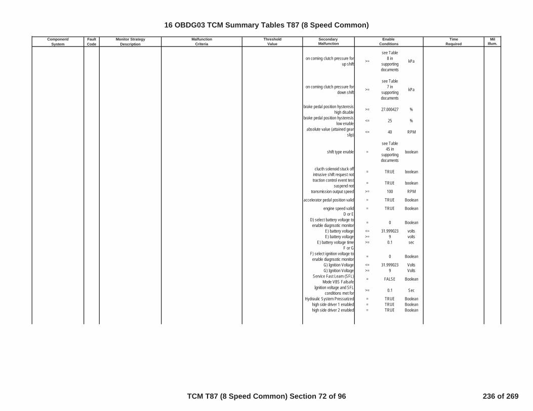
Component/ Fault Monitor Strategy Secondary MilSystem Code Description Malfunction Illum.
Malfunction Threshold Enable TimeCriteria Value Conditions Required
on coming clutch pressure forup shift >=
see Table8 in
supportingdocuments
kPa
on coming clutch pressure fordown shift >=
see Table7 in
supportingdocuments
kPa
brake pedal position hysteresishigh disable >= 27.000427 %
brake pedal position hysteresislow enable <= 25 %
absolute value (attained gearslip) <= 40 RPM
shift type enable =
see Table45 in
supportingdocuments
boolean
clucth solenoid stuck offintrusive shift request not = TRUE boolean
traction control event testsuspend not = TRUE boolean
transmission output speed >= 100 RPM
accelerator pedal position valid = TRUE Boolean
engine speed valid = TRUE BooleanD or E
D) select battery voltage toenable diagnsotic monitor = 0 Boolean
E) battery voltage <= 31.999023 voltsE) battery voltage >= 9 volts
E) battery voltage time >= 0.1 secF or G
F) select ignition voltage toenable diagnsotic monitor = 0 Boolean
G) Ignition Voltage <= 31.999023 VoltsG) Ignition Voltage >= 9 Volts
Service Fast Learn (SFL)Mode VBS Failsafe = FALSE Boolean
Ignition voltage and SFLconditions met for >= 0.1 Sec
Hydraulic System Pressurized = TRUE Booleanhigh side driver 1 enabled = TRUE Booleanhigh side driver 2 enabled = TRUE Boolean
16 OBDG03 TCM Summary Tables T87 (8 Speed Common)
TCM T87 (8 Speed Common) Section 72 of 96 236 of 269

Component/ Fault Monitor Strategy Secondary MilSystem Code Description Malfunction Illum.
Malfunction Threshold Enable TimeCriteria Value Conditions Required
DisableConditions:
MIL not Illuminated forDTC's:
Variable Force Solenoid (VFS) P2718Pressure Control Solenoid D ControlCircuit Open(clutch4/C23468 VFS)
The HWIO reports open crcuiterror flag = TRUE Boolean >= 0.3 Fail Time (Sec)
One Trip
outof 0.5 Sample Time
(Sec)diagnostic monitor enable
calibration = TRUE Boolean
VFS source must be high sidedriver 1 or 2 or 3
high side driver VFS source is = CeTSCR_e_HSD1 enumeration
high side driver VFS sourceenabled = TRUE Boolean
controller power mode state isignition or accessory = TRUE Boolean
battery voltage in range forstability time
battery voltage stability time >= 1 secondsbattery voltage >= 8 voltsbattery voltage <= 32 Volts
DisableConditions:
MIL not Illuminated forDTC's:
Variable Force Solenoid (VFS) P2720Pressure Control Solenoid D ControlCircuit Low(clutch4/C23468 VFS)
The HWIO reports open crcuiterror flag = TRUE Boolean >= 0.3 Fail Time (Sec)
One Trip
outof 0.5 Sample Time
(Sec)diagnostic monitor enable
calibration = TRUE Boolean
VFS source must be high sidedriver 1 or 2 or 3
high side driver VFS source is = CeTSCR_e_HSD1 enumeration
high side driver VFS sourceenabled = TRUE Boolean
controller power mode state isignition or accessory = TRUE Boolean
TCM: P0716, P0717, P0722, P0723,P077C, P077D, P07BF, P07C0, P1824,P182A, P182B, P182C, P182D, P182E,P182F, P1838, P1839, P1840, P1841,P18B5, P18B6, P18B7, P18B8, P18B9,P18BA, P18BB, P18BC, P18BD, P18BE,P18BF, P18C0, P18C1, P18C2, P18C3,P1915, P2534
ECM: P0101, P0102, P0103, P0106,P0107, P0108, P0171, P0172, P0174,P0175, P0201, P0202, P0203, P0204,P0205, P0206, P0207, P0208, P0300,P0301, P0302, P0303, P0304, P0305,P0306, P0307, P0308, P0401, P042E
TCM: None
ECM: None
16 OBDG03 TCM Summary Tables T87 (8 Speed Common)
TCM T87 (8 Speed Common) Section 73 of 96 237 of 269

Component/ Fault Monitor Strategy Secondary MilSystem Code Description Malfunction Illum.
Malfunction Threshold Enable TimeCriteria Value Conditions Required
battery voltage in range forstability time
battery voltage stability time >= 1 secondsbattery voltage >= 8 voltsbattery voltage <= 32 Volts
DisableConditions:
MIL not Illuminated forDTC's:
Variable Force Solenoid (VFS) P2721Pressure Control Solenoid D ControlCircuit High(clutch4/C23468 VFS)
The HWIO reports open crcuiterror flag = TRUE Boolean >= 0.3 Fail Time (Sec)
One Trip
outof 0.5 Sample Time
(Sec)diagnostic monitor enable
calibration = TRUE Boolean
VFS source must be high sidedriver 1 or 2 or 3
high side driver VFS source is = CeTSCR_e_HSD1 enumeration
high side driver VFS sourceenabled = TRUE Boolean
controller power mode state isignition or accessory = TRUE Boolean
battery voltage in range forstability time
battery voltage stability time >= 1 secondsbattery voltage >= 8 voltsbattery voltage <= 32 Volts
DisableConditions:
MIL not Illuminated forDTC's:
Variable Force Solenoid (VFS) P2723 Pressure Control Solenoid E StuckOff (clutch5/C45678R) absolute value (attained gear slip) >= 400 RPM >= 3 seconds One Trip
when fail timereaches fail
limit incrementfail event count
>= 3 event countsclutch solenoid stuck onperformance diagnostic
monitor test deceleration limitnot
= TRUE boolean
clutch solenoid stuck onperformance diagnostic
monitor test return to previousrange not
= TRUE boolean
PRNDL State not = park enumerationPRNDL State not = neutral enumeration
while conditinos A and B andC are met, time down delay
from clibration to 0.0 seconds
TCM: None
ECM: None
TCM: None
ECM: None
16 OBDG03 TCM Summary Tables T87 (8 Speed Common)
TCM T87 (8 Speed Common) Section 74 of 96 238 of 269

Component/ Fault Monitor Strategy Secondary MilSystem Code Description Malfunction Illum.
Malfunction Threshold Enable TimeCriteria Value Conditions Required
delay time calibration = 0.5 secondsA) neutral condition fault
pending = FALSE boolean
B) intrusive shift active = FALSE boolean
C) range shift state = shiftcomplete enumeration
intrusive shift allowed = TRUE booleanintrusive shift active = FALSE boolean
steady state pressure adapt inprogress = FALSE boolean
transmission output speed >= 100 RPMaccelerator pedal position >= 0.5004883 %
accelerator pedal position valid = TRUE Boolean
engine speed valid = TRUE BooleanD or E
D) select battery voltage toenable diagnsotic monitor = 0 Boolean
E) battery voltage <= 31.999023 voltsE) battery voltage >= 9 volts
E) battery voltage time >= 0.1 secF or G
F) select ignition voltage toenable diagnsotic monitor = 0 Boolean
G) Ignition Voltage <= 31.999023 VoltsG) Ignition Voltage >= 9 Volts
Service Fast Learn (SFL)Mode VBS Failsafe = FALSE Boolean
Ignition voltage and SFLconditions met for >= 0.1 Sec
Hydraulic System Pressurized = TRUE Booleanhigh side driver 1 enabled = TRUE Booleanhigh side driver 2 enabled = TRUE Boolean
DisableConditions:
MIL not Illuminated forDTC's:
Variable Force Solenoid (VFS) P2724 Pressure Control Solenoid E StuckOn (clutch5/C45678R)
automatic transmission shifttorque phase test (A) or inertiaphase test (B) fail event count
deceleration limited
>=see Table 32in supportingdocuments
fail event counts
One Trip
TCM: P0716, P0717, P0722, P0723,P077C, P077D, P07BF, P07C0, P1824,P182A, P182B, P182C, P182D, P182E,P182F, P1838, P1839, P1840, P1841,P18B5, P18B6, P18B7, P18B8, P18B9,P18BA, P18BB, P18BC, P18BD, P18BE,P18BF, P18C0, P18C1, P18C2, P18C3,P1915, P2534
ECM: P0101, P0102, P0103, P0106,P0107, P0108, P0171, P0172, P0174,P0175, P0201, P0202, P0203, P0204,P0205, P0206, P0207, P0208, P0300,P0301, P0302, P0303, P0304, P0305,P0306, P0307, P0308, P0401, P042E
16 OBDG03 TCM Summary Tables T87 (8 Speed Common)
TCM T87 (8 Speed Common) Section 75 of 96 239 of 269
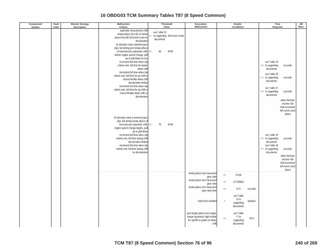
Component/ Fault Monitor Strategy Secondary MilSystem Code Description Malfunction Illum.
Malfunction Threshold Enable TimeCriteria Value Conditions Requiredautomatic transmission shift
torque phase test (A) or inertiaphase test (B) fail event count no
deceleration
>=see Table 33in supportingdocuments
fail event counts
A) absolute value (attained gearslip), fail during post torque phase
of transmission automatic shift,before engine speed change, pull
up or pull down occurs
<= 40 RPM
increment fail time when slipcriteria met, fail time for power
down shift>=
see Table 29in supportingdocuments
seconds
increment fail time when slipcriteria met, fail time for up shift or
closed throttle down shiftdeceleration limited
>=see Table 30in supportingdocuments
seconds
increment fail time when slipcriteria met, fail time for up shift or
closed throttle down shift nodeceleration
>=see Table 31in supportingdocuments
seconds
when fail timereaches fail
limit incrementfail event count
aboveB) absolute value (command gear
slip), fail during inertia phase oftransmission automatic shift,
engine speed change begins, pullup or pull down
>= 70 RPM
increment fail time when slipcriteria met, fail time during shift
deceleration limited>=
see Table 35in supportingdocuments
seconds
increment fail time when slipcriteria met, fail time during shift
no deceleration>=
see Table 36in supportingdocuments
seconds
when fail timereaches fail
limit incrementfail event count
aboveinertia phase test measured
gear ratio >= 0.558
inertia phase test measuredgear ratio <= 4.7150002
inertia phase test measuredgear ratio time >= 0.15 seconds
clutch test enabled =
see Table10 in
supportingdocuments
boolean
post torque phase test enginetorque hysteresis high enablefor upshift or power on down
shift
>=
see Table11 in
supportingdocuments
N*m
16 OBDG03 TCM Summary Tables T87 (8 Speed Common)
TCM T87 (8 Speed Common) Section 76 of 96 240 of 269
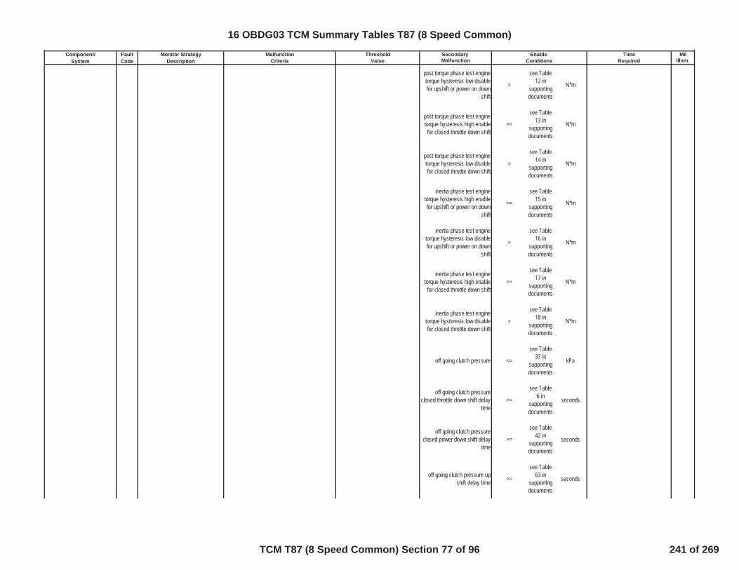
Component/ Fault Monitor Strategy Secondary MilSystem Code Description Malfunction Illum.
Malfunction Threshold Enable TimeCriteria Value Conditions Required
post torque phase test enginetorque hysteresis low disablefor upshift or power on down
shift
>
see Table12 in
supportingdocuments
N*m
post torque phase test enginetorque hysteresis high enablefor closed throttle down shift
>=
see Table13 in
supportingdocuments
N*m
post torque phase test enginetorque hysteresis low disablefor closed throttle down shift
>
see Table14 in
supportingdocuments
N*m
inertia phase test enginetorque hysteresis high enablefor upshift or power on down
shift
>=
see Table15 in
supportingdocuments
N*m
inertia phase test enginetorque hysteresis low disablefor upshift or power on down
shift
>
see Table16 in
supportingdocuments
N*m
inertia phase test enginetorque hysteresis high enablefor closed throttle down shift
>=
see Table17 in
supportingdocuments
N*m
inertia phase test enginetorque hysteresis low disablefor closed throttle down shift
>
see Table18 in
supportingdocuments
N*m
off going clutch pressure <=
see Table37 in
supportingdocuments
kPa
off going clutch pressureclosed throttle down shift delay
time>=
see Table6 in
supportingdocuments
seconds
off going clutch pressureclosed power down shift delay
time>=
see Table42 in
supportingdocuments
seconds
off going clutch pressure upshift delay time >=
see Table63 in
supportingdocuments
seconds
16 OBDG03 TCM Summary Tables T87 (8 Speed Common)
TCM T87 (8 Speed Common) Section 77 of 96 241 of 269

Component/ Fault Monitor Strategy Secondary MilSystem Code Description Malfunction Illum.
Malfunction Threshold Enable TimeCriteria Value Conditions Required
on coming clutch pressure forup shift >=
see Table8 in
supportingdocuments
kPa
on coming clutch pressure fordown shift >=
see Table7 in
supportingdocuments
kPa
brake pedal position hysteresishigh disable >= 27.000427 %
brake pedal position hysteresislow enable <= 25 %
absolute value (attained gearslip) <= 40 RPM
shift type enable =
see Table45 in
supportingdocuments
boolean
clucth solenoid stuck offintrusive shift request not = TRUE boolean
traction control event testsuspend not = TRUE boolean
transmission output speed >= 100 RPM
accelerator pedal position valid = TRUE Boolean
engine speed valid = TRUE BooleanD or E
D) select battery voltage toenable diagnsotic monitor = 0 Boolean
E) battery voltage <= 31.999023 voltsE) battery voltage >= 9 volts
E) battery voltage time >= 0.1 secF or G
F) select ignition voltage toenable diagnsotic monitor = 0 Boolean
G) Ignition Voltage <= 31.999023 VoltsG) Ignition Voltage >= 9 Volts
Service Fast Learn (SFL)Mode VBS Failsafe = FALSE Boolean
Ignition voltage and SFLconditions met for >= 0.1 Sec
Hydraulic System Pressurized = TRUE Booleanhigh side driver 1 enabled = TRUE Booleanhigh side driver 2 enabled = TRUE Boolean
16 OBDG03 TCM Summary Tables T87 (8 Speed Common)
TCM T87 (8 Speed Common) Section 78 of 96 242 of 269

Component/ Fault Monitor Strategy Secondary MilSystem Code Description Malfunction Illum.
Malfunction Threshold Enable TimeCriteria Value Conditions Required
DisableConditions:
MIL not Illuminated forDTC's:
Variable Force Solenoid (VFS) P2727Pressure Control Solenoid E ControlCircuit Open(clutch5/C45678 VFS)
The HWIO reports open crcuiterror flag = TRUE Boolean >= 0.3 Fail Time (Sec)
One Trip
outof 0.5 Sample Time
(Sec)diagnostic monitor enable
calibration = TRUE Boolean
VFS source must be high sidedriver 1 or 2 or 3
high side driver VFS source is = CeTSCR_e_HSD1 enumeration
high side driver VFS sourceenabled = TRUE Boolean
controller power mode state isignition or accessory = TRUE Boolean
battery voltage in range forstability time
battery voltage stability time >= 1 secondsbattery voltage >= 8 voltsbattery voltage <= 32 Volts
DisableConditions:
MIL not Illuminated forDTC's:
Variable Force Solenoid (VFS) P2729Pressure Control Solenoid E ControlCircuit Low(clutch5/C45678 VFS)
The HWIO reports open crcuiterror flag = TRUE Boolean >= 0.3 Fail Time (Sec)
One Trip
outof 0.5 Sample Time
(Sec)diagnostic monitor enable
calibration = TRUE Boolean
VFS source must be high sidedriver 1 or 2 or 3
high side driver VFS source is = CeTSCR_e_HSD1 enumeration
high side driver VFS sourceenabled = TRUE Boolean
controller power mode state isignition or accessory = TRUE Boolean
TCM: P0716, P0717, P0722, P0723,P077C, P077D, P07BF, P07C0, P1824,P182A, P182B, P182C, P182D, P182E,P182F, P1838, P1839, P1840, P1841,P18B5, P18B6, P18B7, P18B8, P18B9,P18BA, P18BB, P18BC, P18BD, P18BE,P18BF, P18C0, P18C1, P18C2, P18C3,P1915, P2534
ECM: P0101, P0102, P0103, P0106,P0107, P0108, P0171, P0172, P0174,P0175, P0201, P0202, P0203, P0204,P0205, P0206, P0207, P0208, P0300,P0301, P0302, P0303, P0304, P0305,P0306, P0307, P0308, P0401, P042E
TCM: None
ECM: None
16 OBDG03 TCM Summary Tables T87 (8 Speed Common)
TCM T87 (8 Speed Common) Section 79 of 96 243 of 269
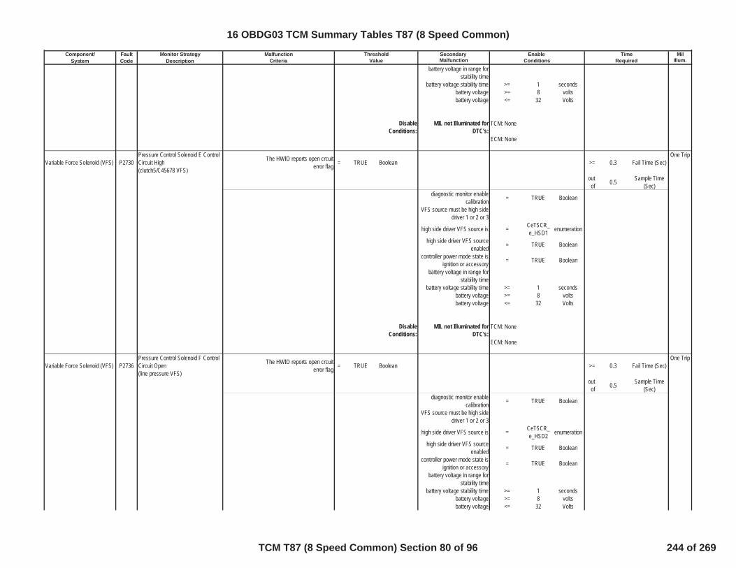
Component/ Fault Monitor Strategy Secondary MilSystem Code Description Malfunction Illum.
Malfunction Threshold Enable TimeCriteria Value Conditions Required
battery voltage in range forstability time
battery voltage stability time >= 1 secondsbattery voltage >= 8 voltsbattery voltage <= 32 Volts
DisableConditions:
MIL not Illuminated forDTC's:
Variable Force Solenoid (VFS) P2730Pressure Control Solenoid E ControlCircuit High(clutch5/C45678 VFS)
The HWIO reports open crcuiterror flag = TRUE Boolean >= 0.3 Fail Time (Sec)
One Trip
outof 0.5 Sample Time
(Sec)diagnostic monitor enable
calibration = TRUE Boolean
VFS source must be high sidedriver 1 or 2 or 3
high side driver VFS source is = CeTSCR_e_HSD1 enumeration
high side driver VFS sourceenabled = TRUE Boolean
controller power mode state isignition or accessory = TRUE Boolean
battery voltage in range forstability time
battery voltage stability time >= 1 secondsbattery voltage >= 8 voltsbattery voltage <= 32 Volts
DisableConditions:
MIL not Illuminated forDTC's:
Variable Force Solenoid (VFS) P2736Pressure Control Solenoid F ControlCircuit Open(line pressure VFS)
The HWIO reports open crcuiterror flag = TRUE Boolean >= 0.3 Fail Time (Sec)
One Trip
outof 0.5 Sample Time
(Sec)diagnostic monitor enable
calibration = TRUE Boolean
VFS source must be high sidedriver 1 or 2 or 3
high side driver VFS source is = CeTSCR_e_HSD2 enumeration
high side driver VFS sourceenabled = TRUE Boolean
controller power mode state isignition or accessory = TRUE Boolean
battery voltage in range forstability time
battery voltage stability time >= 1 secondsbattery voltage >= 8 voltsbattery voltage <= 32 Volts
TCM: None
ECM: None
TCM: None
ECM: None
16 OBDG03 TCM Summary Tables T87 (8 Speed Common)
TCM T87 (8 Speed Common) Section 80 of 96 244 of 269
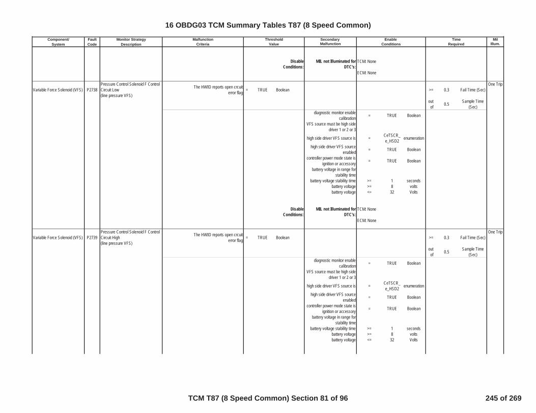
Component/ Fault Monitor Strategy Secondary MilSystem Code Description Malfunction Illum.
Malfunction Threshold Enable TimeCriteria Value Conditions Required
DisableConditions:
MIL not Illuminated forDTC's:
Variable Force Solenoid (VFS) P2738Pressure Control Solenoid F ControlCircuit Low(line pressure VFS)
The HWIO reports open crcuiterror flag = TRUE Boolean >= 0.3 Fail Time (Sec)
One Trip
outof 0.5 Sample Time
(Sec)diagnostic monitor enable
calibration = TRUE Boolean
VFS source must be high sidedriver 1 or 2 or 3
high side driver VFS source is = CeTSCR_e_HSD2 enumeration
high side driver VFS sourceenabled = TRUE Boolean
controller power mode state isignition or accessory = TRUE Boolean
battery voltage in range forstability time
battery voltage stability time >= 1 secondsbattery voltage >= 8 voltsbattery voltage <= 32 Volts
DisableConditions:
MIL not Illuminated forDTC's:
Variable Force Solenoid (VFS) P2739Pressure Control Solenoid F ControlCircuit High(line pressure VFS)
The HWIO reports open crcuiterror flag = TRUE Boolean >= 0.3 Fail Time (Sec)
One Trip
outof 0.5 Sample Time
(Sec)diagnostic monitor enable
calibration = TRUE Boolean
VFS source must be high sidedriver 1 or 2 or 3
high side driver VFS source is = CeTSCR_e_HSD2 enumeration
high side driver VFS sourceenabled = TRUE Boolean
controller power mode state isignition or accessory = TRUE Boolean
battery voltage in range forstability time
battery voltage stability time >= 1 secondsbattery voltage >= 8 voltsbattery voltage <= 32 Volts
TCM: None
ECM: None
TCM: None
ECM: None
16 OBDG03 TCM Summary Tables T87 (8 Speed Common)
TCM T87 (8 Speed Common) Section 81 of 96 245 of 269

Component/ Fault Monitor Strategy Secondary MilSystem Code Description Malfunction Illum.
Malfunction Threshold Enable TimeCriteria Value Conditions Required
DisableConditions:
MIL not Illuminated forDTC's:
VFS characterization P27A7 VFS characterizationclutch1/CB1278R pressure control
solenoid characterization notprogrammed
= TRUE BooleanOne Trip
manufacture enable counter = 0 counts
memory type updated =non-
volatilememory
DisableConditions:
MIL not Illuminated forDTC's:
VFS characterization P27A8 VFS characterizationclutch2/CB12345R pressure
control solenoid characterizationnot programmed
= TRUE BooleanOne Trip
manufacture enable counter = 0 counts
memory type updated =non-
volatilememory
DisableConditions:
MIL not Illuminated forDTC's:
VFS characterization P27A9 VFS characterizationclutch3/C13567 pressure control
solenoid characterization notprogrammed
= TRUE BooleanOne Trip
manufacture enable counter = 0 counts
memory type updated =non-
volatilememory
DisableConditions:
MIL not Illuminated forDTC's:
VFS characterization P27AA VFS characterizationclutch4/C23468 pressure control
solenoid characterization notprogrammed
= TRUE BooleanOne Trip
manufacture enable counter = 0 counts
memory type updated =non-
volatilememory
DisableConditions:
MIL not Illuminated forDTC's:
TCM: None
ECM: None
TCM: None
ECM: None
TCM: None
ECM: None
TCM: None
ECM: None
TCM: None
ECM: None
16 OBDG03 TCM Summary Tables T87 (8 Speed Common)
TCM T87 (8 Speed Common) Section 82 of 96 246 of 269
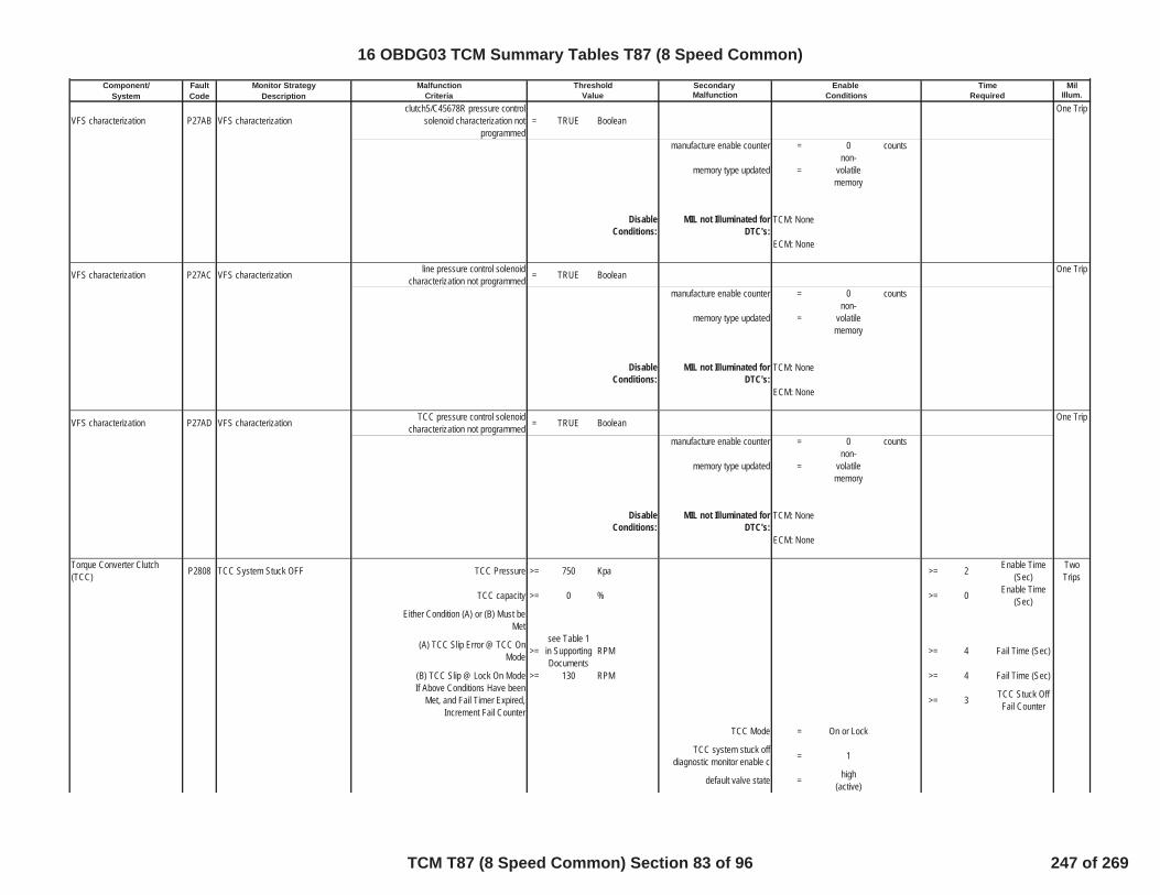
Component/ Fault Monitor Strategy Secondary MilSystem Code Description Malfunction Illum.
Malfunction Threshold Enable TimeCriteria Value Conditions Required
VFS characterization P27AB VFS characterizationclutch5/C45678R pressure control
solenoid characterization notprogrammed
= TRUE BooleanOne Trip
manufacture enable counter = 0 counts
memory type updated =non-
volatilememory
DisableConditions:
MIL not Illuminated forDTC's:
VFS characterization P27AC VFS characterization line pressure control solenoidcharacterization not programmed = TRUE Boolean One Trip
manufacture enable counter = 0 counts
memory type updated =non-
volatilememory
DisableConditions:
MIL not Illuminated forDTC's:
VFS characterization P27AD VFS characterization TCC pressure control solenoidcharacterization not programmed = TRUE Boolean One Trip
manufacture enable counter = 0 counts
memory type updated =non-
volatilememory
DisableConditions:
MIL not Illuminated forDTC's:
Torque Converter Clutch(TCC) P2808 TCC System Stuck OFF TCC Pressure >= 750 Kpa >= 2 Enable Time
(Sec)TwoTrips
TCC capacity >= 0 % >= 0 Enable Time(Sec)
Either Condition (A) or (B) Must beMet
(A) TCC Slip Error @ TCC OnMode >=
see Table 1in SupportingDocuments
RPM >= 4 Fail Time (Sec)
(B) TCC Slip @ Lock On Mode >= 130 RPM >= 4 Fail Time (Sec)If Above Conditions Have been
Met, and Fail Timer Expired,Increment Fail Counter
>= 3 TCC Stuck OffFail Counter
TCC Mode = On or Lock
TCC system stuck offdiagnostic monitor enable c = 1
default valve state = high(active)
TCM: None
ECM: None
TCM: None
ECM: None
TCM: None
ECM: None
16 OBDG03 TCM Summary Tables T87 (8 Speed Common)
TCM T87 (8 Speed Common) Section 83 of 96 247 of 269
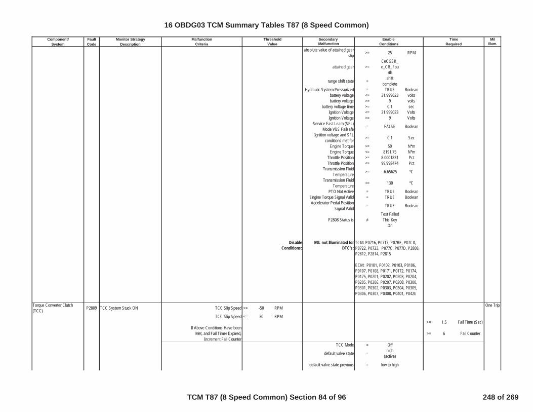
Component/ Fault Monitor Strategy Secondary MilSystem Code Description Malfunction Illum.
Malfunction Threshold Enable TimeCriteria Value Conditions Required
absolute value of attained gearslip >= 25 RPM
attained gear >=CeCGSR_e_CR_Fou
rth
range shift state = shiftcomplete
Hydraulic System Pressurized = TRUE Booleanbattery voltage <= 31.999023 voltsbattery voltage >= 9 volts
battery voltage time >= 0.1 secIgnition Voltage <= 31.999023 VoltsIgnition Voltage >= 9 Volts
Service Fast Learn (SFL)Mode VBS Failsafe = FALSE Boolean
Ignition voltage and SFLconditions met for >= 0.1 Sec
Engine Torque >= 50 N*mEngine Torque <= 8191.75 N*m
Throttle Position >= 8.0001831 PctThrottle Position <= 99.998474 Pct
Transmission FluidTemperature >= -6.65625 ºC
Transmission FluidTemperature <= 130 ºC
PTO Not Active = TRUE BooleanEngine Torque Signal Valid = TRUE BooleanAccelerator Pedal Position
Signal Valid = TRUE Boolean
P2808 Status isTest FailedThis Key
On
DisableConditions:
MIL not Illuminated forDTC's:
Torque Converter Clutch(TCC) P2809 TCC System Stuck ON TCC Slip Speed >= -50 RPM One Trip
TCC Slip Speed <= 30 RPM>= 1.5 Fail Time (Sec)
If Above Conditions Have beenMet, and Fail Timer Expired,
Increment Fail Counter>= 6 Fail Counter
TCC Mode = Off
default valve state = high(active)
default valve state previous = low to high
TCM: P0716, P0717, P07BF, P07C0,P0722, P0723, P077C, P077D, P2808,P2812, P2814, P2815
ECM: P0101, P0102, P0103, P0106,P0107, P0108, P0171, P0172, P0174,P0175, P0201, P0202, P0203, P0204,P0205, P0206, P0207, P0208, P0300,P0301, P0302, P0303, P0304, P0305,P0306, P0307, P0308, P0401, P042E
16 OBDG03 TCM Summary Tables T87 (8 Speed Common)
TCM T87 (8 Speed Common) Section 84 of 96 248 of 269

Component/ Fault Monitor Strategy Secondary MilSystem Code Description Malfunction Illum.
Malfunction Threshold Enable TimeCriteria Value Conditions Required
set default valve state timer =
see Table24 in
SupportingDocument
s
seconds
default valve state timer timesdown to zero (0.0) when
default valve state not= high
(active)
default valve state timer timesdown to zero (0.0) when
default valve state previousnot
= low to high
either A or B ro C must be met
A) default valve state = low to high
B) default valve state timer > 0 secondsC) low TCC slip fail timer > 0 secondsclutch solenoid stuck off
performance (neutral) testactive
= FALSE Boolean
clutch solenoid stuck onperformance (tie-up) test
active= FALSE Boolean
TCC Slip Speed <= 300 RPM
derivative TCC slip speed <=
see Table25 in
SupportingDocument
s
RPM/sec
TCC system stuck ondiagnostic monitor enable c = 1
Engine Speed <= 5500 RPMEngine Speed >= 400 RPM
Vehicle Speed HI <= 45 KPHEngine Torque <= 800 NmEngine Torque >= 55 NmCurrent Range Neutral RangeCurrent Range Reverse Range
Transmission FluidTemperature <= 130 ºC
Transmission FluidTemperature >= -6.65625 ºC
Throttle Position Hyst High >= 3.9993286 PctAND
Max Vehicle Speed to MeetThrottle Enable <= 8 KPH
Once Hyst High has been met,the enable will remain while
Throttle Position>= 0.9994507 Pct
Disable for Throttle Position >= 94.999695 PctDisable if PTO active and
value true = 1
enable if tap up/down mode isfalse or tap up/down TCC
calibration value is false= 0 Boolean
16 OBDG03 TCM Summary Tables T87 (8 Speed Common)
TCM T87 (8 Speed Common) Section 85 of 96 249 of 269
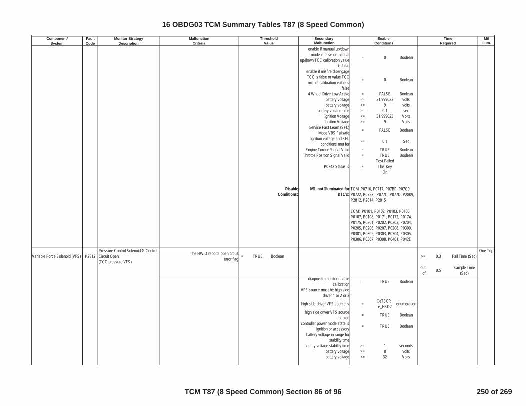
Component/ Fault Monitor Strategy Secondary MilSystem Code Description Malfunction Illum.
Malfunction Threshold Enable TimeCriteria Value Conditions Required
enable if manual up/downmode is false or manual
up/down TCC calibration valueis false
= 0 Boolean
enable if misfire disengageTCC is false or value TCCmisfire calibration value is
false
= 0 Boolean
4 Wheel Drive Low Active = FALSE Booleanbattery voltage <= 31.999023 voltsbattery voltage >= 9 volts
battery voltage time >= 0.1 secIgnition Voltage <= 31.999023 VoltsIgnition Voltage >= 9 Volts
Service Fast Learn (SFL)Mode VBS Failsafe = FALSE Boolean
Ignition voltage and SFLconditions met for >= 0.1 Sec
Engine Torque Signal Valid = TRUE BooleanThrottle Position Signal Valid = TRUE Boolean
P0742 Status isTest FailedThis Key
On
DisableConditions:
MIL not Illuminated forDTC's:
Variable Force Solenoid (VFS) P2812Pressure Control Solenoid G ControlCircuit Open(TCC pressure VFS)
The HWIO reports open crcuiterror flag = TRUE Boolean >= 0.3 Fail Time (Sec)
One Trip
outof 0.5 Sample Time
(Sec)diagnostic monitor enable
calibration = TRUE Boolean
VFS source must be high sidedriver 1 or 2 or 3
high side driver VFS source is = CeTSCR_e_HSD2 enumeration
high side driver VFS sourceenabled = TRUE Boolean
controller power mode state isignition or accessory = TRUE Boolean
battery voltage in range forstability time
battery voltage stability time >= 1 secondsbattery voltage >= 8 voltsbattery voltage <= 32 Volts
TCM: P0716, P0717, P07BF, P07C0,P0722, P0723, P077C, P077D, P2809,P2812, P2814, P2815
ECM: P0101, P0102, P0103, P0106,P0107, P0108, P0171, P0172, P0174,P0175, P0201, P0202, P0203, P0204,P0205, P0206, P0207, P0208, P0300,P0301, P0302, P0303, P0304, P0305,P0306, P0307, P0308, P0401, P042E
16 OBDG03 TCM Summary Tables T87 (8 Speed Common)
TCM T87 (8 Speed Common) Section 86 of 96 250 of 269

Component/ Fault Monitor Strategy Secondary MilSystem Code Description Malfunction Illum.
Malfunction Threshold Enable TimeCriteria Value Conditions Required
DisableConditions:
MIL not Illuminated forDTC's:
Variable Force Solenoid (VFS) P2814Pressure Control Solenoid G ControlCircuit Low(TCC pressure VFS)
The HWIO reports open crcuiterror flag = TRUE Boolean >= 0.3 Fail Time (Sec)
One Trip
outof 0.5 Sample Time
(Sec)diagnostic monitor enable
calibration = TRUE Boolean
VFS source must be high sidedriver 1 or 2 or 3
high side driver VFS source is = CeTSCR_e_HSD2 enumeration
high side driver VFS sourceenabled = TRUE Boolean
controller power mode state isignition or accessory = TRUE Boolean
battery voltage in range forstability time
battery voltage stability time >= 1 secondsbattery voltage >= 8 voltsbattery voltage <= 32 Volts
DisableConditions:
MIL not Illuminated forDTC's:
Variable Force Solenoid (VFS) P2815Pressure Control Solenoid G ControlCircuit High(TCC pressure VFS)
The HWIO reports open crcuiterror flag = TRUE Boolean >= 0.3 Fail Time (Sec)
One Trip
outof 0.5 Sample Time
(Sec)diagnostic monitor enable
calibration = TRUE Boolean
VFS source must be high sidedriver 1 or 2 or 3
high side driver VFS source is = CeTSCR_e_HSD2 enumeration
high side driver VFS sourceenabled = TRUE Boolean
controller power mode state isignition or accessory = TRUE Boolean
battery voltage in range forstability time
battery voltage stability time >= 1 secondsbattery voltage >= 8 voltsbattery voltage <= 32 Volts
DisableConditions:
MIL not Illuminated forDTC's:
TCM: None
ECM: None
TCM: None
ECM: None
TCM: None
ECM: None
16 OBDG03 TCM Summary Tables T87 (8 Speed Common)
TCM T87 (8 Speed Common) Section 87 of 96 251 of 269

Component/ Fault Monitor Strategy Secondary MilSystem Code Description Malfunction Illum.
Malfunction Threshold Enable TimeCriteria Value Conditions Required
default valve on/off valvesolenoid P2817
Hydraulic on/off Control Solenoid HStuck Off (default valve on/offsolenoid)
absolute value (attained gear slip)4th gear commanded >= 400 RPM
6th gear intrusive shiftcommand when fail time
reaches fail limit>= 3 seconds
One Trip
attained gear when intrusive6th gear command = 3rd
attained gear slip 3rd gear <= 75 RPM3rd gear attained time >= 0.5 seconds
intrusive 6th gear commandedevent count >= 2 counts
>= 2 countsclutch solenoid stuck onperformance diagnostic
monitor test deceleration limitnot
= TRUE boolean
clutch solenoid stuck onperformance diagnostic
monitor test return to previousrange not
= TRUE boolean
PRNDL State not = park enumerationPRNDL State not = neutral enumeration
while conditinos A and B andC are met, time down delay
from clibration to 0.0 secondsdelay time calibration = 0.5 seconds
A) neutral condition faultpending = FALSE boolean
B) intrusive shift active = FALSE boolean
C) range shift state = shiftcomplete enumeration
intrusive shift allowed = TRUE booleanintrusive shift active = FALSE boolean
steady state pressure adapt inprogress = FALSE boolean
transmission output speed >= 100 RPMaccelerator pedal position >= 0.5004883 %
accelerator pedal position valid = TRUE Boolean
engine speed valid = TRUE BooleanD or E
D) select battery voltage toenable diagnsotic monitor = 0 Boolean
E) battery voltage <= 31.999023 voltsE) battery voltage >= 9 volts
E) battery voltage time >= 0.1 secF or G
F) select ignition voltage toenable diagnsotic monitor = 0 Boolean
G) Ignition Voltage <= 31.999023 VoltsG) Ignition Voltage >= 9 Volts
Service Fast Learn (SFL)Mode VBS Failsafe = FALSE Boolean
Ignition voltage and SFLconditions met for >= 0.1 Sec
Hydraulic System Pressurized = TRUE Booleanhigh side driver 1 enabled = TRUE Booleanhigh side driver 2 enabled = TRUE Boolean
16 OBDG03 TCM Summary Tables T87 (8 Speed Common)
TCM T87 (8 Speed Common) Section 88 of 96 252 of 269
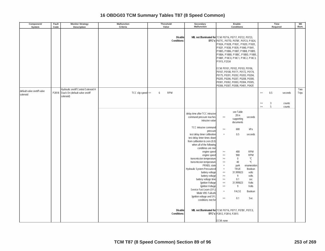
Component/ Fault Monitor Strategy Secondary MilSystem Code Description Malfunction Illum.
Malfunction Threshold Enable TimeCriteria Value Conditions Required
DisableConditions:
MIL not Illuminated forDTC's:
default valve on/off valvesolenoid P2818
Hydraulic on/off Control Solenoid HStuck On (default valve on/offsolenoid)
TCC slip speed <= 6 RPM >= 0.5 secondsTwoTrips
>= 3 counts>= 5 counts
delay time after TCC intrusivecommand pressure reaches
intrusive value>=
see Table28 in
supportingdocuments
seconds
TCC intrusive commandpressure >= 600 kPa
test delay timer calibration = 0.5 secondstest delay timer times down
from calibration to zero (0.0)when all of the following
conditinos are metengine speed >= 400 RPMengine speed <= 900 RPM
transmission temperature >= 0 ºCtransmission temperature <= 40 ºC
PRNDL state = park enumerationHydraulic System Pressurized = TRUE Boolean
battery voltage <= 31.999023 voltsbattery voltage >= 9 volts
battery voltage time >= 0.1 secIgnition Voltage <= 31.999023 VoltsIgnition Voltage >= 9 Volts
Service Fast Learn (SFL)Mode VBS Failsafe = FALSE Boolean
Ignition voltage and SFLconditions met for >= 0.1 Sec
DisableConditions:
MIL not Illuminated forDTC's:
TCM: P0716, P0717, P0722, P0723,P077C, P077D, P07BF, P07C0, P1824,P182A, P182B, P182C, P182D, P182E,P182F, P1838, P1839, P1840, P1841,P18B5, P18B6, P18B7, P18B8, P18B9,P18BA, P18BB, P18BC, P18BD, P18BE,P18BF, P18C0, P18C1, P18C2, P18C3,P1915, P2534
ECM: P0101, P0102, P0103, P0106,P0107, P0108, P0171, P0172, P0174,P0175, P0201, P0202, P0203, P0204,P0205, P0206, P0207, P0208, P0300,P0301, P0302, P0303, P0304, P0305,P0306, P0307, P0308, P0401, P042E
TCM: P0716, P0717, P07BF, P07C0,P2812, P2814, P2815
ECM: none
16 OBDG03 TCM Summary Tables T87 (8 Speed Common)
TCM T87 (8 Speed Common) Section 89 of 96 253 of 269

Component/ Fault Monitor Strategy Secondary MilSystem Code Description Malfunction Illum.
Malfunction Threshold Enable TimeCriteria Value Conditions Required
default valve on/off solenoid P281DPressure Control Solenoid H ControlCircuit Low(default valve on/off solenoid)
The HWIO reports open crcuiterror flag = TRUE Boolean >= 0.3 Fail Time (Sec)
One Trip
outof 0.5 Sample Time
(Sec)diagnostic monitor enable
calibration = TRUE Boolean
VFS source must be high sidedriver 1 or 2 or 3
high side driver VFS source is = CeTSCR_e_HSD1 enumeration
high side driver VFS sourceenabled = TRUE Boolean
controller power mode state isignition or accessory = TRUE Boolean
battery voltage in range forstability time
battery voltage stability time >= 1 secondsbattery voltage >= 8 voltsbattery voltage <= 32 Volts
DisableConditions:
MIL not Illuminated forDTC's:
default valve on/off solenoid P281EPressure Control Solenoid H ControlCircuit High(default valve on/off solenoid)
The HWIO reports open crcuiterror flag = TRUE Boolean >= 0.3 Fail Time (Sec)
One Trip
outof 0.5 Sample Time
(Sec)diagnostic monitor enable
calibration = TRUE Boolean
VFS source must be high sidedriver 1 or 2 or 3
high side driver VFS source is = CeTSCR_e_HSD1 enumeration
high side driver VFS sourceenabled = TRUE Boolean
controller power mode state isignition or accessory = TRUE Boolean
battery voltage in range forstability time
battery voltage stability time >= 1 secondsbattery voltage >= 8 voltsbattery voltage <= 32 Volts
DisableConditions:
MIL not Illuminated forDTC's:
clutch2/CB12345R boost valveon/off solenoid P2824
Pressure Control Solenoid J ControlCircuit High(clutch2/CB12345R boost valveon/off solenoid)
The HWIO reports open crcuiterror flag = TRUE Boolean >= 0.3 Fail Time (Sec)
One Trip
TCM: None
ECM: None
TCM: None
ECM: None
16 OBDG03 TCM Summary Tables T87 (8 Speed Common)
TCM T87 (8 Speed Common) Section 90 of 96 254 of 269

Component/ Fault Monitor Strategy Secondary MilSystem Code Description Malfunction Illum.
Malfunction Threshold Enable TimeCriteria Value Conditions Required
outof 0.5 Sample Time
(Sec)diagnostic monitor enable
calibration = TRUE Boolean
VFS source must be high sidedriver 1 or 2 or 3
high side driver VFS source is = CeTSCR_e_HSD1 enumeration
high side driver VFS sourceenabled = TRUE Boolean
controller power mode state isignition or accessory = TRUE Boolean
battery voltage in range forstability time
battery voltage stability time >= 1 secondsbattery voltage >= 8 voltsbattery voltage <= 32 Volts
DisableConditions:
MIL not Illuminated forDTC's:
clutch2/CB12345R boost valveon/off solenoid P2826
Pressure Control Solenoid J ControlCircuit Low(clutch2/CB12345R boost valveon/off solenoid)
The HWIO reports open crcuiterror flag = TRUE Boolean >= 0.3 Fail Time (Sec)
One Trip
outof 0.5 Sample Time
(Sec)diagnostic monitor enable
calibration = TRUE Boolean
VFS source must be high sidedriver 1 or 2 or 3
high side driver VFS source is = CeTSCR_e_HSD2 enumeration
high side driver VFS sourceenabled = TRUE Boolean
controller power mode state isignition or accessory = TRUE Boolean
battery voltage in range forstability time
battery voltage stability time >= 1 secondsbattery voltage >= 8 voltsbattery voltage <= 32 Volts
DisableConditions:
MIL not Illuminated forDTC's:
clutch2/CB12345R boost valveon/off solenoid P2827
Pressure Control Solenoid J ControlCircuit High(clutch2/CB12345R boost valveon/off solenoid)
The HWIO reports open crcuiterror flag = TRUE Boolean >= 0.3 Fail Time (Sec)
One Trip
outof 0.5 Sample Time
(Sec)
TCM: None
ECM: None
TCM: None
ECM: None
16 OBDG03 TCM Summary Tables T87 (8 Speed Common)
TCM T87 (8 Speed Common) Section 91 of 96 255 of 269
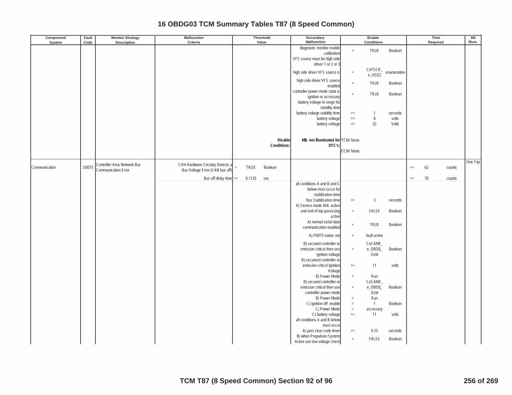
Component/ Fault Monitor Strategy Secondary MilSystem Code Description Malfunction Illum.
Malfunction Threshold Enable TimeCriteria Value Conditions Required
diagnostic monitor enablecalibration = TRUE Boolean
VFS source must be high sidedriver 1 or 2 or 3
high side driver VFS source is = CeTSCR_e_HSD2 enumeration
high side driver VFS sourceenabled = TRUE Boolean
controller power mode state isignition or accessory = TRUE Boolean
battery voltage in range forstability time
battery voltage stability time >= 1 secondsbattery voltage >= 8 voltsbattery voltage <= 32 Volts
DisableConditions:
MIL not Illuminated forDTC's:
Communication U0073 Controller Area Network BusCommunication Error
CAN Hardware Circuitry Detects aBus Voltage Error (CAN bus off) = TRUE Boolean >= 62 counts
One Trip
Bus off delay time >= 0.1125 sec >= 70 countsall conditions A and B and C
below must occur forstabilization time
Bus Stabilization time >= 3 secondsA) Service mode $04 active
and end of trip pocessingactive
= FALSE Boolean
A) normal serial datacommunication enabled = TRUE Boolean
A) P0073 status not = fault active
B) secured controller oremission critical then use
ignition voltage=
CeCANR_e_OBDII_
DsblBoolean
B) secureed controller oremission critical Ignition
Voltage>= 11 volts
B) Power Mode = RunB) secured controller or
emission critical then usecontroller power mode
=CeCANR_e_OBDII_
DsblBoolean
B) Power Mode = RunC) ignition off enable = 1 Boolean
C) Power Mode = accessoryC) battery voltage >= 11 volts
all conditions A and B belowmust occur
A) post clear code timer >= 0.15 secondsB) when Propulsion System
Active use low voltage check = FALSE Boolean
TCM: None
ECM: None
16 OBDG03 TCM Summary Tables T87 (8 Speed Common)
TCM T87 (8 Speed Common) Section 92 of 96 256 of 269
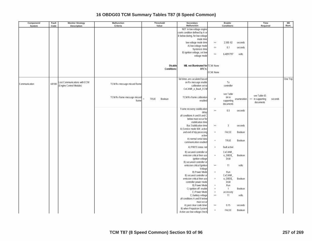
Component/ Fault Monitor Strategy Secondary MilSystem Code Description Malfunction Illum.
Malfunction Threshold Enable TimeCriteria Value Conditions Required
NOT in low voltage enginecrank condition defined by A orB below during, for low voltage
mode timelow voltage mode time >= 2.50E-02 seconds
A) low voltage modehysteresis time <= 0.1 seconds
B) ignition voltage, set lowvoltage mode <= 6.4091797 volts
DisableConditions:
MIL not Illuminated forDTC's:
Communication U0100 Lost Communications with ECM(Engine Control Module) TCM Rx message missed frame
fail times are caculated basedon Rx message enable
calibration set toCeCANR_e_BusA_ECM
Txcontroller
One Trip
TCM Rx frame message missedframe = TRUE Boolean TCM Rx frame calibration
enabled
see Table64 in
supportingdocuments
enumeration >=see Table 65in supportingdocuments
seconds
Frame recovery stabilizationdelay >= 0.5 seconds
all conditions A and B and Cbelow must occur for
stabilization timeBus Stabilization time >= 3 seconds
A) Service mode $04 activeand end of trip pocessing
active= FALSE Boolean
A) normal serial datacommunication enabled = TRUE Boolean
A) P0073 status not = fault active
B) secured controller oremission critical then use
ignition voltage=
CeCANR_e_OBDII_
DsblBoolean
B) secureed controller oremission critical Ignition
Voltage>= 11 volts
B) Power Mode = RunB) secured controller or
emission critical then usecontroller power mode
=CeCANR_e_OBDII_
DsblBoolean
B) Power Mode = RunC) ignition off enable = 1 Boolean
C) Power Mode = accessoryC) battery voltage >= 11 volts
all conditions A and B belowmust occur
A) post clear code timer >= 0.15 secondsB) when Propulsion System
Active use low voltage check = FALSE Boolean
TCM: None
ECM: None
16 OBDG03 TCM Summary Tables T87 (8 Speed Common)
TCM T87 (8 Speed Common) Section 93 of 96 257 of 269
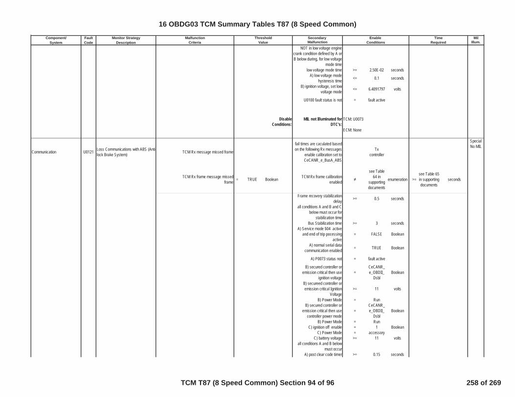
Component/ Fault Monitor Strategy Secondary MilSystem Code Description Malfunction Illum.
Malfunction Threshold Enable TimeCriteria Value Conditions Required
NOT in low voltage enginecrank condition defined by A orB below during, for low voltage
mode timelow voltage mode time >= 2.50E-02 seconds
A) low voltage modehysteresis time <= 0.1 seconds
B) ignition voltage, set lowvoltage mode <= 6.4091797 volts
U0100 fault status is not = fault active
DisableConditions:
MIL not Illuminated forDTC's:
Communication U0121 Loss Communications with ABS (Anti-lock Brake System) TCM Rx message missed frame
fail times are caculated basedon the following Rx messages
enable calibration set toCeCANR_e_BusA_ABS
Txcontroller
SpecialNo MIL
TCM Rx frame message missedframe = TRUE Boolean TCM Rx frame calibration
enabled
see Table64 in
supportingdocuments
enumeration >=see Table 65in supportingdocuments
seconds
Frame recovery stabilizationdelay >= 0.5 seconds
all conditions A and B and Cbelow must occur for
stabilization timeBus Stabilization time >= 3 seconds
A) Service mode $04 activeand end of trip pocessing
active= FALSE Boolean
A) normal serial datacommunication enabled = TRUE Boolean
A) P0073 status not = fault active
B) secured controller oremission critical then use
ignition voltage=
CeCANR_e_OBDII_
DsblBoolean
B) secureed controller oremission critical Ignition
Voltage>= 11 volts
B) Power Mode = RunB) secured controller or
emission critical then usecontroller power mode
=CeCANR_e_OBDII_
DsblBoolean
B) Power Mode = RunC) ignition off enable = 1 Boolean
C) Power Mode = accessoryC) battery voltage >= 11 volts
all conditions A and B belowmust occur
A) post clear code timer >= 0.15 seconds
TCM: U0073
ECM: None
16 OBDG03 TCM Summary Tables T87 (8 Speed Common)
TCM T87 (8 Speed Common) Section 94 of 96 258 of 269

Component/ Fault Monitor Strategy Secondary MilSystem Code Description Malfunction Illum.
Malfunction Threshold Enable TimeCriteria Value Conditions Required
B) when Propulsion SystemActive use low voltage check = FALSE Boolean
NOT in low voltage enginecrank condition defined by A orB below during, for low voltage
mode timelow voltage mode time >= 2.50E-02 seconds
A) low voltage modehysteresis time <= 0.1 seconds
B) ignition voltage, set lowvoltage mode <= 6.4091797 volts
U0121 fault status is not = fault active
DisableConditions:
MIL not Illuminated forDTC's:
Communication U0140 Loss Communications with BCM(Body Control Module) TCM Rx message missed frame
fail times are caculated basedon the following Rx messages
enable calibration set toCeCANR_e_BusA_BCM
Txcontroller
SpecialNo MIL
TCM Rx frame message missedframe = TRUE Boolean TCM Rx frame calibration
enabled
see Table64 in
supportingdocuments
enumeration >=see Table 65in supportingdocuments
seconds
Frame recovery stabilizationdelay >= 0.5 seconds
all conditions A and B and Cbelow must occur for
stabilization timeBus Stabilization time >= 3 seconds
A) Service mode $04 activeand end of trip pocessing
active= FALSE Boolean
A) normal serial datacommunication enabled = TRUE Boolean
A) P0073 status not = fault active
B) secured controller oremission critical then use
ignition voltage=
CeCANR_e_OBDII_
DsblBoolean
B) secureed controller oremission critical Ignition
Voltage>= 11 volts
B) Power Mode = RunB) secured controller or
emission critical then usecontroller power mode
=CeCANR_e_OBDII_
DsblBoolean
B) Power Mode = RunC) ignition off enable = 1 Boolean
C) Power Mode = accessoryC) battery voltage >= 11 volts
TCM: U0073
ECM: None
16 OBDG03 TCM Summary Tables T87 (8 Speed Common)
TCM T87 (8 Speed Common) Section 95 of 96 259 of 269

Component/ Fault Monitor Strategy Secondary MilSystem Code Description Malfunction Illum.
Malfunction Threshold Enable TimeCriteria Value Conditions Required
all conditions A and B belowmust occur
A) post clear code timer >= 0.15 secondsB) when Propulsion System
Active use low voltage check = FALSE Boolean
NOT in low voltage enginecrank condition defined by A orB below during, for low voltage
mode timelow voltage mode time >= 2.50E-02 seconds
A) low voltage modehysteresis time <= 0.1 seconds
B) ignition voltage, set lowvoltage mode <= 6.4091797 volts
U0140 fault status is not = fault active
16 OBDG03 TCM Summary Tables T87 (8 Speed Common)
TCM T87 (8 Speed Common) Section 96 of 96 260 of 269
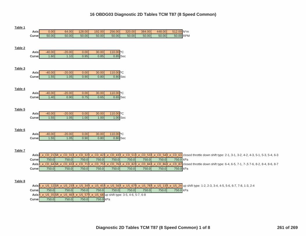
Table 1Axis 0.00 64.00 128.00 192.00 256.00 320.00 384.00 448.00 512.00 N*m
Curve 50.00 50.00 50.00 50.00 50.00 50.00 50.00 50.00 50.00 RPM
Table 2Axis -40.00 -20.00 0.00 30.00 110.00 ºC
Curve 1.60 1.10 0.95 0.85 0.85 Sec
Table 3Axis -40.00 -20.00 0.00 30.00 110.00 ºC
Curve 1.55 1.05 0.90 0.80 0.80 Sec
Table 4Axis -40.00 -20.00 0.00 30.00 110.00 ºC
Curve 1.40 0.90 0.75 0.65 0.65 Sec
Table 5Axis -40.00 -20.00 0.00 30.00 110.00 ºC
Curve 1.55 1.05 1.00 1.00 1.00 Sec
Table 6Axis -40.00 -20.00 0.00 30.00 110.00 ºC
Curve 1.55 1.05 0.90 0.80 0.80 Sec
Table 7AxisR_e_CD_21SSR_e_CD_31R_e_CD_32R_e_CD_42R_e_CD_43R_e_CD_51R_e_CD_53R_e_CD_54R_e_CD_63 closed throttle down shift type: 2-1, 3-1, 3-2, 4-2, 4-3, 5-1, 5-3, 5-4, 6-3
Curve 750.0 750.0 750.0 750.0 750.0 750.0 750.0 750.0 750.0 kPaAxisR_e_CD_64SSR_e_CD_65R_e_CD_71R_e_CD_75R_e_CD_76R_e_CD_82R_e_CD_84R_e_CD_86R_e_CD_87 closed throttle down shift type: 6-4, 6-5, 7-1, 7-,5 7-6, 8-2, 8-4, 8-6, 8-7
Curve 750.0 750.0 750.0 750.0 750.0 750.0 750.0 750.0 750.0 kPa
Table 8AxisR_e_US_12SSR_e_US_23R_e_US_34R_e_US_45R_e_US_56R_e_US_67R_e_US_78R_e_US_13R_e_US_24 up shift type: 1-2, 2-3, 3-4, 4-5, 5-6, 6-7, 7-8, 1-3, 2-4
Curve 750.0 750.0 750.0 750.0 750.0 750.0 750.0 750.0 750.0 kPaAxisR_e_US_35SSR_e_US_46R_e_US_57R_e_US_68 up shift type: 3-5, 4-6, 5-7, 6-8
Curve 750.0 750.0 750.0 750.0 kPa
16 OBDG03 Diagnostic 2D Tables TCM T87 (8 Speed Common)
Diagnostic 2D Tables TCM T87 (8 Speed Common) 1 of 8 261 of 269
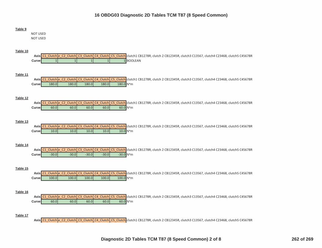
Table 9NOT USEDNOT USED
Table 10Axis_C1_Clutch_e_C2_Clutch_C3_Clutch_C4_Clutch_C5_Clutch clutch1 CB1278R, clutch 2 CB12345R, clutch3 C13567, clutch4 C23468, clutch5 C45678R
Curve 1 1 1 1 1 BOOLEAN
Table 11Axis_C1_Clutch_e_C2_Clutch_C3_Clutch_C4_Clutch_C5_Clutch clutch1 CB1278R, clutch 2 CB12345R, clutch3 C13567, clutch4 C23468, clutch5 C45678R
Curve 180.0 180.0 180.0 180.0 180.0 N*m
Table 12Axis_C1_Clutch_e_C2_Clutch_C3_Clutch_C4_Clutch_C5_Clutch clutch1 CB1278R, clutch 2 CB12345R, clutch3 C13567, clutch4 C23468, clutch5 C45678R
Curve 60.0 60.0 60.0 60.0 60.0 N*m
Table 13Axis_C1_Clutch_e_C2_Clutch_C3_Clutch_C4_Clutch_C5_Clutch clutch1 CB1278R, clutch 2 CB12345R, clutch3 C13567, clutch4 C23468, clutch5 C45678R
Curve 10.0 10.0 10.0 10.0 10.0 N*m
Table 14Axis_C1_Clutch_e_C2_Clutch_C3_Clutch_C4_Clutch_C5_Clutch clutch1 CB1278R, clutch 2 CB12345R, clutch3 C13567, clutch4 C23468, clutch5 C45678R
Curve -30.0 -30.0 -30.0 -30.0 -30.0 N*m
Table 15Axis_C1_Clutch_e_C2_Clutch_C3_Clutch_C4_Clutch_C5_Clutch clutch1 CB1278R, clutch 2 CB12345R, clutch3 C13567, clutch4 C23468, clutch5 C45678R
Curve 100.0 100.0 100.0 100.0 100.0 N*m
Table 16Axis_C1_Clutch_e_C2_Clutch_C3_Clutch_C4_Clutch_C5_Clutch clutch1 CB1278R, clutch 2 CB12345R, clutch3 C13567, clutch4 C23468, clutch5 C45678R
Curve 60.0 60.0 60.0 60.0 60.0 N*m
Table 17Axis_C1_Clutch_e_C2_Clutch_C3_Clutch_C4_Clutch_C5_Clutch clutch1 CB1278R, clutch 2 CB12345R, clutch3 C13567, clutch4 C23468, clutch5 C45678R
16 OBDG03 Diagnostic 2D Tables TCM T87 (8 Speed Common)
Diagnostic 2D Tables TCM T87 (8 Speed Common) 2 of 8 262 of 269

Curve 10.0 10.0 10.0 10.0 10.0 N*m
Table 18Axis_C1_Clutch_e_C2_Clutch_C3_Clutch_C4_Clutch_C5_Clutch clutch1 CB1278R, clutch 2 CB12345R, clutch3 C13567, clutch4 C23468, clutch5 C45678R
Curve -30.0 -30.0 -30.0 -30.0 -30.0 N*m
Table 19NOT USEDNOT USED
Table 20NOT USEDNOT USED
Table 21Axis -40.00 0.00 40.00 ºC
Curve 5.00 5.00 5.00 Sec
Table 22NOT USEDNOT USED
Table 23NOT USEDNOT USED
Table 24Axis -7.00 10.00 40.00 ºC
Curve 1.50 1.25 1.00 Sec
16 OBDG03 Diagnostic 2D Tables TCM T87 (8 Speed Common)
Diagnostic 2D Tables TCM T87 (8 Speed Common) 3 of 8 263 of 269

Table 25Axis -7.00 10.00 40.00 ºC
Curve -2000.00 -2000.00 -2000.00 RPM/Sec
Table 26Axis -40.00 -30.00 -20.00 0.00 20.00 ºC
Curve 1800.00 1500.00 1200.00 600.00 60.00 Sec
Table 27Axis 0.00 20.00 60.00 100.00 120.00 Kph
Curve -8.00 -8.00 -8.00 -8.00 -8.00 ºC
Table 28Axis -40.00 -20.00 0.00 30.00 110.00 ºC
Curve 5.00 3.00 2.00 1.75 1.00 Sec
Table 29Axis_C1_Clutch_e_C2_Clutch_C3_Clutch_C4_Clutch_C5_Clutch clutch1 CB1278R, clutch 2 CB12345R, clutch3 C13567, clutch4 C23468, clutch5 C45678R
Curve 0.9000 0.9000 0.9000 0.9000 0.9000 seconds
Table 30Axis_C1_Clutch_e_C2_Clutch_C3_Clutch_C4_Clutch_C5_Clutch clutch1 CB1278R, clutch 2 CB12345R, clutch3 C13567, clutch4 C23468, clutch5 C45678R
Curve 0.9000 0.9000 0.9000 0.9000 0.9000 seconds
Table 31Axis_C1_Clutch_e_C2_Clutch_C3_Clutch_C4_Clutch_C5_Clutch clutch1 CB1278R, clutch 2 CB12345R, clutch3 C13567, clutch4 C23468, clutch5 C45678R
Curve 0.9000 0.9000 0.9000 0.9000 0.9000 seconds
Table 32Axis_C1_Clutch_e_C2_Clutch_C3_Clutch_C4_Clutch_C5_Clutch clutch1 CB1278R, clutch 2 CB12345R, clutch3 C13567, clutch4 C23468, clutch5 C45678R
Curve 4 4 4 4 4 counts
16 OBDG03 Diagnostic 2D Tables TCM T87 (8 Speed Common)
Diagnostic 2D Tables TCM T87 (8 Speed Common) 4 of 8 264 of 269

Table 33Axis_C1_Clutch_e_C2_Clutch_C3_Clutch_C4_Clutch_C5_Clutch clutch1 CB1278R, clutch 2 CB12345R, clutch3 C13567, clutch4 C23468, clutch5 C45678R
Curve 4 4 4 4 4 counts
Table 34NOT USEDNOT USED
Table 35Axis_C1_Clutch_e_C2_Clutch_C3_Clutch_C4_Clutch_C5_Clutch clutch1 CB1278R, clutch 2 CB12345R, clutch3 C13567, clutch4 C23468, clutch5 C45678R
Curve 0.5000 0.5000 0.5000 0.5000 0.5000 seconds
Table 36Axis_C1_Clutch_e_C2_Clutch_C3_Clutch_C4_Clutch_C5_Clutch clutch1 CB1278R, clutch 2 CB12345R, clutch3 C13567, clutch4 C23468, clutch5 C45678R
Curve 0.5000 0.5000 0.5000 0.5000 0.5000 seconds
Table 37Axis_C1_Clutch_e_C2_Clutch_C3_Clutch_C4_Clutch_C5_Clutch clutch1 CB1278R, clutch 2 CB12345R, clutch3 C13567, clutch4 C23468, clutch5 C45678R
Curve 300.0 300.0 300.0 300.0 300.0 kPa
Table 38Axis -40.00 -20.00 0.00 30.00 110.00 ºC
Curve 0.95 0.45 0.30 0.30 0.30 Sec
Table 39Axis -40.00 -20.00 0.00 30.00 110.00 ºC
Curve 0.95 0.45 0.30 0.20 0.20 Sec
Table 40Axis -40.00 -20.00 0.00 30.00 110.00 ºC
Curve 0.95 0.45 0.30 0.20 0.20 Sec
16 OBDG03 Diagnostic 2D Tables TCM T87 (8 Speed Common)
Diagnostic 2D Tables TCM T87 (8 Speed Common) 5 of 8 265 of 269
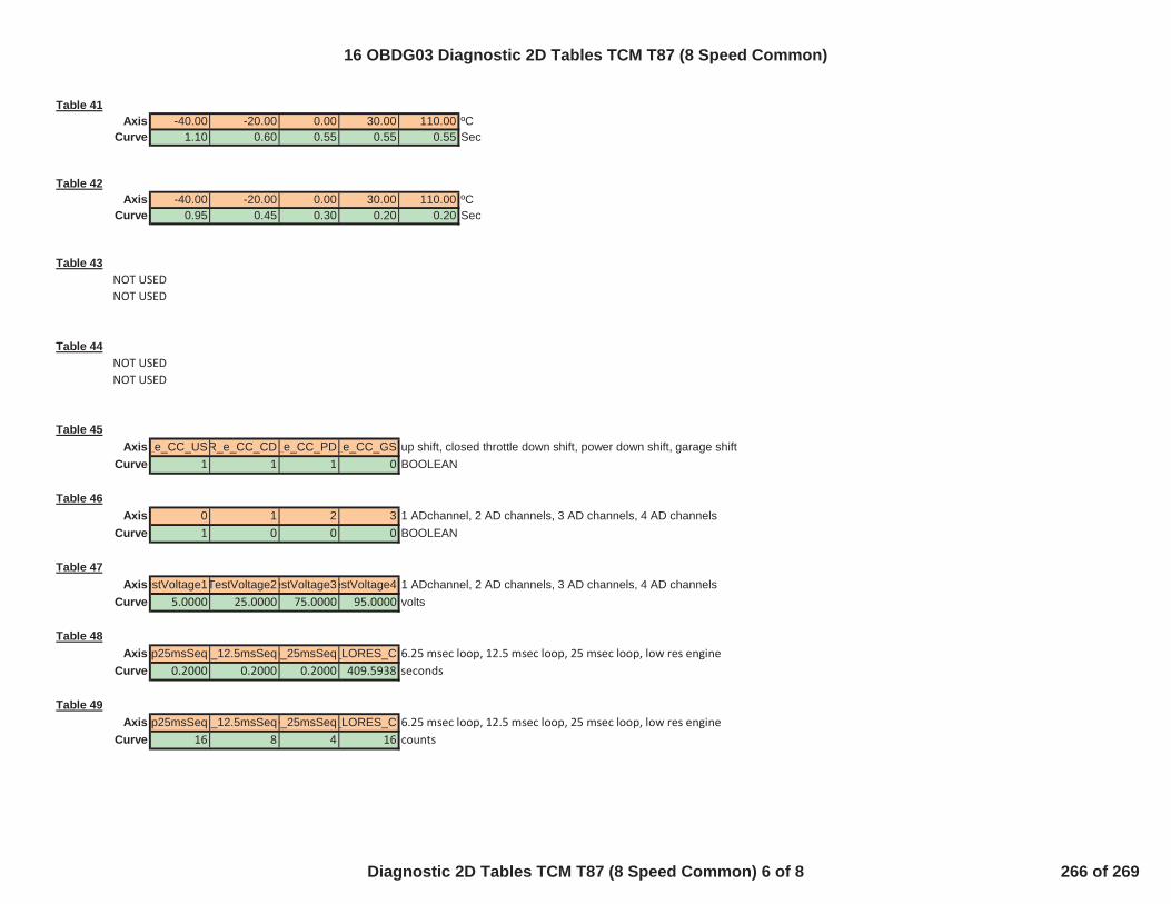
Table 41Axis -40.00 -20.00 0.00 30.00 110.00 ºC
Curve 1.10 0.60 0.55 0.55 0.55 Sec
Table 42Axis -40.00 -20.00 0.00 30.00 110.00 ºC
Curve 0.95 0.45 0.30 0.20 0.20 Sec
Table 43NOT USEDNOT USED
Table 44NOT USEDNOT USED
Table 45Axis_e_CC_USR_e_CC_CD_e_CC_PD_e_CC_GS up shift, closed throttle down shift, power down shift, garage shift
Curve 1 1 1 0 BOOLEAN
Table 46Axis 0 1 2 3 1 ADchannel, 2 AD channels, 3 AD channels, 4 AD channels
Curve 1 0 0 0 BOOLEAN
Table 47AxisestVoltage1TestVoltage2estVoltage3estVoltage4 1 ADchannel, 2 AD channels, 3 AD channels, 4 AD channels
Curve 5.0000 25.0000 75.0000 95.0000 volts
Table 48Axis6p25msSeqe_12.5msSeqe_25msSeq_LORES_C 6.25 msec loop, 12.5 msec loop, 25 msec loop, low res engine
Curve 0.2000 0.2000 0.2000 409.5938 seconds
Table 49Axis6p25msSeqe_12.5msSeqe_25msSeq_LORES_C 6.25 msec loop, 12.5 msec loop, 25 msec loop, low res engine
Curve 16 8 4 16 counts
16 OBDG03 Diagnostic 2D Tables TCM T87 (8 Speed Common)
Diagnostic 2D Tables TCM T87 (8 Speed Common) 6 of 8 266 of 269

Table 50AxisR_i_MontrAMR_i_MontrBR_i_MontrC seed key test enable, seed sequence test enable, seed timeout test enable
Curve 1 0 0 BOOLEAN
Table 51Axis 0 1 speed sensor1, speed sensor2
Curve 0.2500 0.0000 volts
Table 52Axis 0 1 speed sensor1, speed sensor2
Curve 40 65535 counts
Table 53Axis 0 1 speed sensor1, speed sensor2
Curve 0.0500 409.5938 seconds
Table 54Axis 0 1 speed sensor1, speed sensor2
Curve 1 0 BOOLEAN
Table 55Axis 0 1 speed sensor1, speed sensor2
Curve 4.7500 12.0000 volts
Table 56Axis 0 1 speed sensor1, speed sensor2
Curve 40 65535 counts
Table 57Axis 0 1 speed sensor1, speed sensor2
Curve 0.0500 409.5938 seconds
Table 58Axis 0 1 speed sensor circuit low, speed sensor circuit high
Curve 1 0 BOOLEAN
16 OBDG03 Diagnostic 2D Tables TCM T87 (8 Speed Common)
Diagnostic 2D Tables TCM T87 (8 Speed Common) 7 of 8 267 of 269
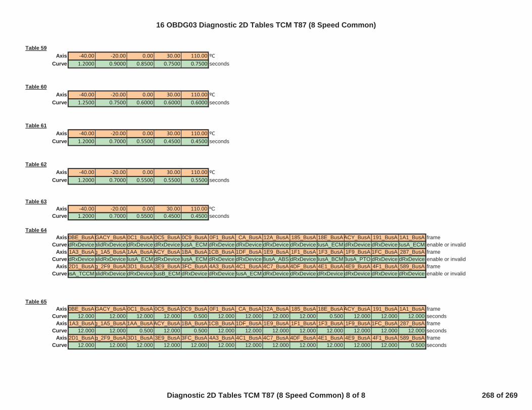
Table 59Axis -40.00 -20.00 0.00 30.00 110.00 ºC
Curve 1.2000 0.9000 0.8500 0.7500 0.7500 seconds
Table 60Axis -40.00 -20.00 0.00 30.00 110.00 ºC
Curve 1.2500 0.7500 0.6000 0.6000 0.6000 seconds
Table 61Axis -40.00 -20.00 0.00 30.00 110.00 ºC
Curve 1.2000 0.7000 0.5500 0.4500 0.4500 seconds
Table 62Axis -40.00 -20.00 0.00 30.00 110.00 ºC
Curve 1.2000 0.7000 0.5500 0.5500 0.5500 seconds
Table 63Axis -40.00 -20.00 0.00 30.00 110.00 ºC
Curve 1.2000 0.7000 0.5500 0.4500 0.4500 seconds
Table 64Axis_0BE_BusA GACY_BusA_0C1_BusA_0C5_BusA_0C9_BusA_0F1_BusA _CA_BusA_12A_BusA_185_BusA_18E_BusAACY_BusA_191_BusA_1A1_BusA frame
Curve dRxDevicealidRxDevice dRxDevice dRxDeviceBusA_ECM dRxDevice dRxDevice dRxDevice dRxDeviceBusA_ECM dRxDevice dRxDeviceBusA_ECM enable or invalidAxis_1A3_BusAg_1A5_BusA_1AA_BusAACY_BusA_1BA_BusA 1CB_BusA_1DF_BusA_1E9_BusA_1F1_BusA_1F3_BusA_1F9_BusA_1FC_BusA_287_BusA frame
Curve dRxDevicealidRxDeviceBusA_ECM dRxDeviceBusA_ECM dRxDevice dRxDevice BusA_ABS dRxDeviceBusA_BCMBusA_PTO dRxDevice dRxDevice enable or invalidAxis_2D1_BusAg_2F9_BusA_3D1_BusA_3E9_BusA_3FC_BusA_4A3_BusA_4C1_BusA_4C7_BusA_4DF_BusA_4E1_BusA_4E9_BusA_4F1_BusA_589_BusA frame
CurveusA_TCCMalidRxDevice dRxDeviceBusB_ECM dRxDevice dRxDeviceBusA_ECM dRxDevice dRxDevice dRxDevice dRxDevice dRxDevice dRxDevice enable or invalid
Table 65Axis_0BE_BusA GACY_BusA_0C1_BusA_0C5_BusA_0C9_BusA_0F1_BusA _CA_BusA_12A_BusA_185_BusA_18E_BusAACY_BusA_191_BusA_1A1_BusA frame
Curve 12.000 12.000 12.000 12.000 0.500 12.000 12.000 12.000 12.000 0.500 12.000 12.000 12.000 secondsAxis_1A3_BusAg_1A5_BusA_1AA_BusAACY_BusA_1BA_BusA 1CB_BusA_1DF_BusA_1E9_BusA_1F1_BusA_1F3_BusA_1F9_BusA_1FC_BusA_287_BusA frame
Curve 12.000 12.000 0.500 12.000 0.500 12.000 12.000 12.000 12.000 12.000 12.000 12.000 12.000 secondsAxis_2D1_BusAg_2F9_BusA_3D1_BusA_3E9_BusA_3FC_BusA_4A3_BusA_4C1_BusA_4C7_BusA_4DF_BusA_4E1_BusA_4E9_BusA_4F1_BusA_589_BusA frame
Curve 12.000 12.000 12.000 12.000 12.000 12.000 12.000 12.000 12.000 12.000 12.000 12.000 0.500 seconds
16 OBDG03 Diagnostic 2D Tables TCM T87 (8 Speed Common)
Diagnostic 2D Tables TCM T87 (8 Speed Common) 8 of 8 268 of 269

3D_Table 1 CeTSKR_Cnt_MaxCPUs X-Axis Calibration CPUCePISR_e_NumOfSeqTasks Y-Axis Calibration CePISR_e_6p25msSeq CePISR_e_12p5msSeq CePISR_e_25msSeq CePISR_e_LORES_C CePISR_e_6p25msSeq CePISR_e_12p5msSeq CePISR_e_25msSeq CePISR_e_LORES_C loop test ty
KaPISD_b_ProgSeqWatchEnbl Table Calibration 1 1 1 0 0 0 0 0 BOOLEAN
CeTSKR_e_CPU CeTSKR_e_CPU2
16 OBDG03 Diagnostic 3D Tables TCM T87 (8 Speed Common)
Diagnostic 3D Tables TCM T87 (8 Speed Common) 1 of 1 269 of 269