bridge structures - mackay council€¦ · contract no. bridge structures ... welded wire...
TRANSCRIPT

Contract No. BRIDGE STRUCTURES
© The AUS-SPEC Joint Venture date: Dec 2008 Copying strictly prohibited AUS-SPEC-1\QLD-C340 Jan 2009 MACKAY REGIONAL COUNCIL
QUEENSLAND
CONSTRUCTION SPECIFICATION
C340
BRIDGE STRUCTURES


Contract No. BRIDGE STRUCTURES
© The AUS-SPEC Joint Venture date: Dec 2008 Copying strictly prohibited AUS-SPEC-1\QLD-C340 Jan 2009 MACKAY REGIONAL COUNCIL
SPECIFICATION C340 : BRIDGE STRUCTURES
CLAUSE CONTENTS PAGE
GENERAL………………………………………………………………………………………......2
C340.01 SCOPE…………………………………………...………………………………………………………...2
C340/02 REFERENCE DOCUMENTS…………………..…………………………………………………….…..2
CONSTRUCTION………………………………………………………………………………….3
C340.03 GENERAL……………………………………….……………………………………………………...…3
C340.04 DRIVEN PILES………………………………….…………………………………………..………….…3
C340.05 STRUCTURAL CONCRETE………………………………………….………………………………….6
C340.06 STEEL REINFORCEMENT……………………..……………………………………………………...31
C340.07 FORMWORK (CAST-IN-SITU CONCRETE)….……………………………………….……………..34
C340.08 PRECAST CONCRETE UNITS…………….......………………………………….…………………..35
C340.09 FABRICATION OF STEELWORK……………...………………………………….…………………..37
C340.10 STEEL BRIDGE BARRIERS……………………………..……………………………..……………...42
C340.11 BEACHING……………………………………….………….………..…………………………………43
MEASUREMENT AND PAYMENT………………………….…………...…………………………………………45
C340.12 PAY ITEMS……………………………………….………..…….………………………………………45


Contract No. BRIDGE STRUCTURES
© The AUS-SPEC Joint Venture date: Dec 2008 Copying strictly prohibited AUS-SPEC-1\QLD-C340 Jan 2009 MACKAY REGIONAL COUNCIL
Amendment Record for this Specification Part
This Specification is Council’s edition of the AUS-SPEC generic specification part and includes Council’s primary amendments.
Details are provided below outlining the clauses amended from the Council edition of this AUS-SPEC Specification Part. The clause numbering and context of each clause are preserved. New clauses are added towards the rear of the specification part as special requirements clauses. Project specific additional script is shown in the specification as italic font.
The amendment code indicated below is ‘A’ for additional script ‘M’ for modification to script and ‘O’ for omission of script. An additional code ‘P’ is included when the amendment is project specific.
Amendment Sequence
Key topic Addressed in Amendment
Clause No.
Amendment Code
Author Initials Amendment Date

Contract No. BRIDGE STRUCTURES
© The AUS-SPEC Joint Venture date: Apr 2000 Copying strictly prohibited
AUS-SPEC-1\QLD-C340 Jan 2009 MACKAY REGIONAL COUNCIL
2
SPECIFICATION C340 : BRIDGE STRUCTURES
GENERAL
C340.01 SCOPE
1. This Specification covers the construction of precast bolted bridge sections including piles, head rocks, deck plates & guardrail.
2. Requirements for quality control and testing, including maximum lot sizes and minimum test frequencies, are cited in the Specification Part for Quality Requirements.
C340.02 REFERENCE DOCUMENTS
1. Documents referenced in this Specification are listed in full below whilst being cited in the text in the abbreviated form or code indicated
(a) Council Specifications
C101 - General C201 - Control of Traffic C211 - Control of Erosion & Sedimentation C212 - Cleaning & Grubbing C213 - Earthworks
(b) Australian Standards AUSTROADS - Bridge Design Code AS2159 - Piling Design & Installation AS3972 - Portland & Blended Cements AS1379 - The Specification & Supply of Concrete AS1012 - Methods of Testing Concrete AS1141 - Methods of Sampling & Testing Aggregates AS1478 - Chemical Admixtures for Concrete AS2758.1 - Aggregate & Rock for Engineering Purposes - Concrete Aggregates AS3582 - Supply Cementitious Materials for use with Portland Cement Concrete AS3582.1 - Part 1: Fly Ash AS3582.2 - Part 2: Slag – Ground Granulated Iron Blast Furnace AS3582.3 - Part 3: Silica Fume AS3799 - Liquid Membrane – Forming Curing Compounds for Concrete AS1304 - Welded Wire Reinforcing Fabric for Concrete AS/NZS4671 - Steel Reinforcing Materials AS3610 - Formwork for Concrete AS1163 - Structural Steel Hollow Sections AS1594 - Hot-Rolled Steel Flat Products AS3678 - Structural Steel – Hot-Rolled Plates, Floorplates and Slabs AS3679 - Structural Steel Part 1 - Hot-Rolled Bars and Sections Part 2 - Welded Sections AS1111 - ISO metric Hexagonal Commercial Bolts and Screws AS1112 - ISO Metric Hexagonal Nuts, Including Nuts, Slotted Nuts & Castle Nuts AS1214 - Hot dip Galvanized Coatings on Threaded Fasteners AS1252 - High Strength Steel Bolts with Associated Nuts and washers for Structural
Engineering AS1443 - Carbon Steels and Carbon Manganese Steels – Cold-Finished Bars AS/NZS1554 - Structural Steel Welding Code Part 1 - Welding of Steel Structures

Contract No. BRIDGE STRUCTURES
© The AUS-SPEC Joint Venture date: Apr 2000 Copying strictly prohibited
AUS-SPEC-1\QLD-C340 Jan 2009 MACKAY REGIONAL COUNCIL
3
Part 2 - Stud Welding (steel studs to steel) Part 5 – Welding of Steel Structures Subject to High Levels of Fatigue Loading AS4100 - Steel Structures AS1100 - Technical Drawings AS1101 - Graphical Symbols for General Engineering AS/NZS4680 - Hot Dipped Galvanized (Zinc) Coatings on Fabricated Ferrous Articles AS3600 - Concrete Structures
CONSTRUCTION C340.03 GENERAL
1. Bridge construction shall be undertaken in accordance with the Drawings & Specifications provided.
2. All necessary permits and approvals for the completion of the works shall be obtained by the Contractor prior to site works commencing.
3. Co-ordination of Works
The Contractor shall be responsible for a letter drop to relevant authorities and abutting residences or other residents that will be affected as a result of the construction works. Notification is to be sent at least 3 weeks prior to works commencing work on site.
The letter shall be submitted to Council for approval and shall include the Contractor’s company details, contact name and contact numbers of the contact person of the contractor. It also shall provide a contact name and telephone number for the Council’s supervisor. It also must detail the duration of the construction period.
In addition the Contractor is required to serve notice to other relevant authorities such as bus companies, Police etc.
4. Works Program
Tenderers must supply a works program with their tender submission. The successful Tenderer shall revise and resubmit their works program, updated for the Contract commencement and completion dates, for approval prior to commencement of the Works.
C340.04 DRIVEN PILES
1. General
Piles shall be handled and driven in the locations and to the elevations shown on the drawings, or as directed by the Superintendent. Care must be taken that piles are not damaged by improperly supporting, handling or transporting.
Each pile shall have the length marked clearly at 500 mm intervals starting from the toe of the pile.
Unless otherwise specified, piles shall be driven in accordance with AS2159 Piling – Design and Installation.
2. Driving System
Piles shall be driven with a driving system which delivers sufficient driving energy to install the pile and to achieve an ultimate capacity in excess of the specified pile test load without causing damage to the pile.
For a drop hammer, the height of fall required to produce this energy shall not exceed 2 m.
The Contractor shall provide details of the driving system including the make, model and rated energy of the hammer, the mass of the helmet, and the proposed cap-block and cushion materials.

Contract No. BRIDGE STRUCTURES
© The AUS-SPEC Joint Venture date: Apr 2000 Copying strictly prohibited
AUS-SPEC-1\QLD-C340 Jan 2009 MACKAY REGIONAL COUNCIL
4
These details, including calculations which demonstrate that the proposed driving system has sufficient energy to achieve the specified pile test load, shall be submitted to the Superintendent for review not less then 14 days prior to commencing pile driving.
3. Driving
During driving, the tops of the piles shall be held and guided by a suitable helmet and protected by a cushioning material, so as to minimise damage to the pile.
Piles shall not be bent or sprung into place during or after driving, but shall be effectively guided to finish in the position specified herein.
Each pile shall be driven as a continuous operation and no pile shall be left partly driven.
Splicing of piles shall be carried out immediately driving of any section has ceased. Re-driving shall commence as soon as the splice is completed.
The following tolerances shall apply to piles after driving:
(1) pile head shall finish within 50 mm of the specified position;
(2) variation from the vertical or from the specified rake shall be not more than 20 mm in 1 m;
(3) in case of piers with piles capped at crosshead level, the pile at ground level shall be within 50 mm of specified position;
(4) in case of steel shell piles, no pile shall vary from the straight by more than 5 mm per metre of total length of the pile.
Piles shall be driven to the contract levels shown on the Drawings unless otherwise approved by the Superintendent.
Any piles forced up by the driving of adjacent piles shall be re-driven to the specified pile test load and toe level. If the ultimate capacity is not achieved at the contract level specified, the pile shall be re-tested in accordance with Clause 340.04(7). Alternatively, if directed by the Superintendent, the pile shall be driven on until the specified pile test load is achieved.
The Contractor shall use all means considered necessary to ensure the pile reaches the specified contract level within the accuracy of position as specified above.
Whenever it is necessary to drive the head of the pile below the level of the underside of the pile cap, care shall be taken to minimise disturbance of the surrounding ground when driving or extending the pile.
Piles driven through abutment fill shall be pre-bored to the depth of the fill. The diameter of the prebored hole shall not exceed 50 mm less than diagonal dimension of the pile.
After pile driving is completed all voids shall be filled with grout or sand.
After driving piles the area shall be reinstated and any damaged made good.
4. Axial Load Capacity of Driven Piles
Each pile shall be driven to an ultimate capacity which shall be confirmed by testing using the method described below to achieve the appropriate pile test load shown on the Drawings.
The pile test loads shown on the drawings are determined by the designer in accordance with Austroads Bridge Design Code which gives the basis for determining the Material Factor. Pile testing shall be carried out in the presence of the Superintendent. (Hold Point)

Contract No. BRIDGE STRUCTURES
© The AUS-SPEC Joint Venture date: Apr 2000 Copying strictly prohibited
AUS-SPEC-1\QLD-C340 Jan 2009 MACKAY REGIONAL COUNCIL
5
5. PDA Testing
(a) General
Dynamic pile testing shall be performed to confirm that the design pile capacity and integrity has been achieved.
The test procedure and test reports shall conform with the requirements of AS 2159.
Testing shall be carried out by use of a Pile Driving Analyser (PDA) and the data obtained from each pile shall be analysed using CAPWAP or TNOWAVE or approved equivalent software.
The driving resistance and corresponding set per blow of the pile shall be measured during PDA testing in order to extrapolate the results of the test pile to other piles in the group.
The measured ultimate capacity of the test pile shall be equal to or greater than the pile test load shown on the Drawings. The remaining piles in the group shall be driven to a set corresponding to the ‘represented’ pile test load shown on the Drawings.
(b) Driving Criteria
The driving criteria for each pile group shall be determined by testing the first pile driven in each group in accordance with Clause 340.04 (5)(a)
The pile test will determine the driving set for each pile group by correlating the driving system and design pile capacity. All piles within that group shall be driven to a set exceeding the driving set as determined by PDA test for that pile group.
Where a pier or abutment has more than one pile cap, the piles within each pile cap shall be considered as a separate pile group.
For large pile groups the number of piles tested shall be a minimum of 1 in 30, and the distance of any pile from the test pile shall not exceed 20 metres.
An additional pile test shall be carried out where the driving conditions are no longer represented by the initial pile test for that pile group. Additional pile test are required where:
- pile toe levels vary by more than 2 metres from the test pile, or,
- pile rake differs by more than 8 degrees from the test pile.
6. Restrike Test
Restrike testing shall be carried out, where required or when directed, not less than 12 hours after initial driving.
The pile will be accepted if the driving resistance is equal to or greater than the pile test load shown on the drawings.
7. Concrete Piles
Each pile shall have the date of casting clearly marked thereon.
All concrete piles shall be fitted with an approval steel or cast iron driving shoe.
Piles shall be handled and stored so that they are not overstressed and in such a way as to prevent permanent distortion of any part.
Piles shall not be driven until the specified concrete strength has been achieved.
Contract No. BRIDGE STRUCTURES
© The AUS-SPEC Joint Venture date: Apr 2000 Copying strictly prohibited
AUS-SPEC-1\QLD-C340 Jan 2009 MACKAY REGIONAL COUNCIL
6
Piles shall not be driven until 14 days minimum after the date of casting where exposed surfaces have been moist cured or 7 days minimum after the date of casting where steam curing is employed and provided the specified concrete strength has been achieved.
8. Extension to RC Piles
Reinforced concrete piles may be extended by either an additional length of precast reinforced concrete pile or by means of a cast in place reinforced concrete extension subject to:
(a) The pile extension shall be of the same cross-sectional dimensions as the connecting pile. The concrete strength shall be not less than that specified for the connecting pile.
(b) The maximum angular deviation at a pile joint shall not exceed 1 in 100.
(c) (i) Precast extensions may be used provided all the following conditions apply -
(1) an approved type of mechanical joint is used;
(2) the precast extension has a minimum length of 5 metres; and
(3) the joint location is approved by the design engineer.
(ii) Cast in place extensions may be used provided that they are capable of developing the full structural capacity of the pile including the bending and tensile capacities and durability classification shown on the drawings
Any welding of reinforcement carried out as part of the extension shall be in accordance with AS 1554, Part 1.
Design of the extension shall be approved by the design engineer.
Driving shall not commence until the concrete in the extension has achieved the specified concrete strength in the connecting pile and at least 75% of the concrete strength grade for the concrete in the extension.
9. Defective Piles
Where a pile exceeds the specified tolerances, is damaged or is otherwise defective, the strength, serviceability and durability of the pile shall be reappraised and where found to be unsatisfactory the pile shall be repaired, downgraded or replaced with one or more supplementary piles subject to the approval of the Superintendent.
C340.05 STRUCTURAL CONCRETE
1. General
This section specifies the requirements for durability, strength and surface finish for structural concrete.
Additional requirements for concrete for post-tensioned, precast, sprayed concrete and other types of concrete construction are specified in the relevant sections of this specification.
Concrete using general purpose Portland cement Type GP or blended cement Type GB shall comply with the requirements of AS 3972 “Portland and Blended Cements”. In addition, blended cement Type GB shall consist of a specified minimum quantity of Portland cement in combination with any one or two of Ground Granulated Blast Furnace Slag (GGBF Slag), Fly Ash or Silica Fume and as specified in this section.
All concrete shall be special class performance concrete in accordance with Appendix B of AS 1379 “The Specification and Supply of Concrete”.
The durability requirements for concrete & exposure classification will be as shown on the drawings.

Contract No. BRIDGE STRUCTURES
© The AUS-SPEC Joint Venture date: Apr 2000 Copying strictly prohibited
2. Definitions
Cement: Material complying with the requirements of AS 3972 and as specified in this section.
Portland Cement: General purpose Portland cement Type GP complying with the requirements of AS 3972.
Blended Cement: General purpose blended cement Type GB complying with the requirements of AS 3972 and as specified in this section.
Supplementary Cementitious Material: Fly Ash, Ground Granulated Blast Furnace Slag (GGBF Slag), or Silica Fume complying with the requirements of AS 3582.1, AS 3582.2 and AS 3582.3 respectively.
Cementitious Material: Portland cement or a mixture of Portland cement with one or more supplementary Cementitious materials.
Water/Cementitious Material Ratio: The ratio of the amount of water to the total amount of Cementitious materials by mass in a freshly mixed cubic metre of concrete. The water shall be the total free water contained in the batch aggregates in excess of their saturated surface-dry condition.
Concrete Grade: A grade of concrete with a specified minimum cementitious material content, a maximum water/cementitious material ratio and a minimum compressive strength at 3, 7 and 28 days.
Exposure Classification: As per Table 5.4.3 of Australian Bridge Design Code and summarised as follows:
A - Mild C - Very Severe
B1 - Moderately Severe U - Special Consider ation
B2 - Severe
VPV: % Apparent Volume of Permeable Voids as determined by test method AS 1012.21.
Triple Blend: Blended cement Type GB consisting of a minimum quantity of Portland cement in combination with any two Supplementary Cementitious Materials (i.e. any two of Fly Ash, GGBF Slag or Silica Fume).
3. Durability
Durability requirements with respect to exposure classification and concrete grade shall be as shown on the drawings and as specified in this section.
4. Minimum Compressive Strength
The minimum compressive strength requirements for each concrete grade are shown in Table C340.1.
Table C340.1
Minimum Compressive Strength (MPa) Concrete Grade 3 days 7 days 28 days
32 40 50 55
15 18 23 25
24 30 40 45
32 40 50 55
5. Maximum VPV at 28 Day
The maximum VPV values at 28 days for each concrete grade for both test cylinders and test cores including sprayed concrete are shown in Table C340.2.
AUS-SPEC-1\QLD-C340 Jan 2009 MACKAY REGIONAL COUNCIL
7
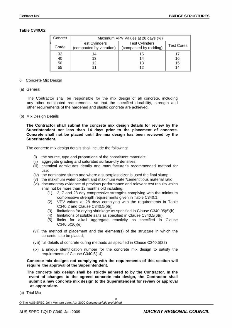
Contract No. BRIDGE STRUCTURES
© The AUS-SPEC Joint Venture date: Apr 2000 Copying strictly prohibited
Table C340.02
Maximum VPV Values at 28 days (%) Concrete
Grade Test Cylinders
(compacted by vibration) Test Cylinders
(compacted by rodding) Test Cores
32 40 50 55
14 13 12 11
15 14 13 12
17 16 15 14
6. Concrete Mix Design (a) General The Contractor shall be responsible for the mix design of all concrete, including any other nominated requirements, so that the specified durability, strength and other requirements of the hardened and plastic concrete are achieved. (b) Mix Design Details
The Contractor shall submit the concrete mix design details for review by the Superintendent not less than 14 days prior to the placement of concrete. Concrete shall not be placed until the mix design has been reviewed by the Superintendent. The concrete mix design details shall include the following:
(i) the source, type and proportions of the constituent materials; (ii) aggregate grading and saturated surface-dry densities; (iii) chemical admixtures details and manufacturer’s recommended method for
use; (iv) the nominated slump and where a superplasticizer is used the final slump; (v) the maximum water content and maximum water/cementitious material ratio; (vi) documentary evidence of previous performance and relevant test results which
shall not be more than 12 months old including: (1) 3, 7 and 28 day compressive strengths complying with the minimum
compressive strength requirements given in Table C340.1; (2) VPV values at 28 days complying with the requirements in Table
C340.2 and Clause C340.5(6)(j) (3) limitations for drying shrinkage as specified in Clause C340.05(6)(h) (4) limitations of soluble salts as specified in Clause C340.5(6)(i) (5) limits for alkali aggregate reactivity as specified in Clause
C340.5(10)(e)
(vii) the method of placement and the element(s) of the structure in which the concrete is to be placed;
(viii) full details of concrete curing methods as specified in Clause C340.5(22)
(ix) a unique identification number for the concrete mix design to satisfy the requirements of Clause C340.5(14)
Concrete mix designs not complying with the requirements of this section will require the approval of the Superintendent.
The concrete mix design shall be strictly adhered to by the Contractor. In the event of changes to the agreed concrete mix design, the Contractor shall submit a new concrete mix design to the Superintendent for review or approval as appropriate.
(c) Trial Mix
AUS-SPEC-1\QLD-C340 Jan 2009 MACKAY REGIONAL COUNCIL
8

Contract No. BRIDGE STRUCTURES
© The AUS-SPEC Joint Venture date: Apr 2000 Copying strictly prohibited
In the absence of recent documentary evidence that the concrete mix design complies with the requirements of this section, a trial mix shall be undertaken in accordance with AS 1012.2.
The relevant results of the trial mix and the associated concrete mix design details indicating compliance with the specified requirements, shall be submitted for review by the Superintendent.
(d) Mix Constituents
The concrete shall consist of a mixture of cementitious material, fine aggregate, coarse aggregate and water.
The concrete may also contain chemical admixtures, details of which shall be submitted with the mix design.
If the course aggregate or fine aggregate is composed of more than one material or size of material, the mix proportions for each shall be specified separately.
(e) Cementitious Material Content and Water/Cementitious Material Ratio
The minimum mass of total cementitious material per cubic metre of finished concrete and the corresponding maximum water/cementitious material ratio shall be shown in Table C340.3
Table C340.3 Concrete Grade
Cementitious Material Content (min) (kg/m3)
Water/Cementitious Material Ratio (max)
32
40
50
55
330
400
450
470
0.50
0.45
0.40
0.36
The cementitious material content of concrete to be placed under water shall not be less than 400 kg/m3, with a maximum water/cementitious material ratio of 0.45.
(f) The minimum mass of Portland cement in concrete mixes containing either GGBF Slag, Fly Ash or Silica Fume shall be 60%, 75% or 90% respectively, of the total mass of cementitious material in the concrete mix. The inclusion of GGBF Slag, Fly Ash or Silica Fume in concrete mixes shall only be in single or double combination with Portland cement. In a triple blend concrete mix, the Portland cement content shall be a minimum of 60% and the individual contribution of GGBF Slag, Fly Ash or Silica Fume shall be a maximum of 40%, 25% or 10% respectively, of the total mass of the cementitious material in the concrete mix.
(g) Use of Supplementary Cementitious Materials for Special Applications
Supplementary cementitious materials requirements for special applications shall be as specified on the drawings and in this specification.
(i) Limitations on Drying Shrinkage
One sample per trial mix shall be taken. Each sample shall consist of 3 specimens tested in accordance with AS 1012.13. The shrinkage strain of each sample, as determined from the average value of the 3 specimens, shall not exceed 750 x 10-6 after 56 days of drying.
(ii) Soluble Salts
(i) Chloride-ion Content
AUS-SPEC-1\QLD-C340 Jan 2009 MACKAY REGIONAL COUNCIL
9

Contract No. BRIDGE STRUCTURES
© The AUS-SPEC Joint Venture date: Apr 2000 Copying strictly prohibited
AUS-SPEC-1\QLD-C340 Jan 2009 MACKAY REGIONAL COUNCIL
10
The maximum acid-soluble chloride-ion content of concrete as placed, expressed as the percentage of the total mass cementitious material in the concrete mix shall not be greater than:
- 0.1% for prestressed concrete
- 0.15% for reinforced concrete
- 0.03% for post-tensioning grout.
(ii) Sulphate Content
The sulphate content of concrete as placed, expressed as the percentage by mass of acid-soluble SO3 to the total cementitious material in the concrete mix shall not be greater than 5%.
Sulphate and chloride-ion content shall be determined by testing of hardened concrete in accordance with AS 1012.20
(j) Testing and Acceptance of Concrete Mix Design on the Basis of 28 Day VPV Value
Test cylinders shall be cured in accordance with AS 1012. A minimum of 2 cylinders per sample per trial mix shall be taken. Each cylinder shall be tested for VPV at 28 days in accordance with test method AS 1012.21. The specification will be satisfied if the VPV value for each sample, as determined from the average value of the test cylinders, is not greater than the specified maximum 28 day VPV value in Table C340.2
Should the VPV value of any one sampling representing the concrete exceed the specified maximum 28 day VPV value as shown in Table C340.2, the Contractor shall take steps to modify the concrete mix design and re-test to ensure that the maximum specified VPV value is not exceed.
7. Cement, Fly ash, GGBF Slag and Silica Fume
(a) Cement
Cement shall comply with the requirements of AS 3972. Cement per batch of concrete shall be from one manufacturer and of one brand, type and grind.
(b) Fly Ash, GGBF Slag and Silica Fume
Fly Ash, GGBF Slag and Silica Fume shall comply with requirements of AS 3582.1, AS 3582.2 and AS 3582.3 respectively and shall be from one manufacturer and of one brand, type and fineness.
8. Water
The quality of mixing water to be used in the concrete mix shall comply with the requirements of Clause 2.4 of AS 1379. However, the amounts of chloride and chlorine in the water shall be not greater than 0.03%.
9. Chemical Admixtures
Chemical admixtures shall comply with the requirements of AS 1478 unless otherwise specified in the section. They shall be used in accordance with the requirements of Clause 2.5 of AS 1379 and the manufacturer’s recommended method of use and shall not reduce the strength of concrete below that specified,
Chemical admixtures shall not contain calcium chloride, calcium formate, chlorine, sulphur, sulphides or sulphites.
Where two or more chemical admixtures are proposed for incorporation in a concrete mix, their compatibility shall be certified by the manufacturers.
Air entraining admixtures shall not be used unless approved by the Superintendent.

Contract No. BRIDGE STRUCTURES
© The AUS-SPEC Joint Venture date: Apr 2000 Copying strictly prohibited
Where the use of air entraining admixture is approved, the air content of the concrete delivered on site shall not exceed the nominal value of 5%.
The Contractor shall determine the air content of the freshly mixed concrete at the point of discharge in accordance with AS 1012.4 and Clause AS 1379.
The concrete represented by a sample taken in accordance with Clause C340.5(15) shall be deemed to comply with the approved air content if the measured air content is within 1.5 percent of the approved air content.
10. Aggregates
(a) General
Fine and coarse aggregate for concrete shall comply with the requirements of AS 2758.1 unless otherwise specified.
(b) Fine Aggregate
(i) Description
The fine aggregate shall consist of clean, hard, durable, naturally occurring grains, or a combination of naturally occurring grains and crusher fines, and shall be free from clay, dust, lumps, soft or flaky particles, shale, salt, alkali, organic matter, soil or other deleterious substances. Crusher fines produced from any igneous or metamorphic rock shall have a Degradation Factor – Crusher Fines of not less then 60.
A maximum of 20% of crushed fine aggregate from a source approved by the Superintendent will be permitted.
(ii) Testing for Impurities
Fine aggregate shall be tested for impurities in accordance with AS 1141.
(iii) Grading of Fine Aggregate
Fine aggregate shall be uniformly graded and shall comply with the limits in Table C340.4 when tested with standard sieves.
If required fine aggregates can be combined in such proportions that the resulting fine aggregate mix shall comply with the grading requirements.
Table C340.4 Sieve Size AS (mm)
Percentage Passing (by mass)
9.5 4.75 2.36 1.18 0.6 0.3
0.15 0.075
100 90 – 100 75 – 100 50 – 90 30 – 70 10 – 35 2 – 10 0 - 3
AUS-SPEC-1\QLD-C340 Jan 2009 MACKAY REGIONAL COUNCIL
11

Contract No. BRIDGE STRUCTURES
© The AUS-SPEC Joint Venture date: Apr 2000 Copying strictly prohibited
AUS-SPEC-1\QLD-C340 Jan 2009 MACKAY REGIONAL COUNCIL
12
(iv) Consistence of Grading
The grading of fine aggregate shall not deviate from the submitted grading by more than ±5%.
(c) Source Rock
Source rock shall comply with the requirements of AS 2758.1 section, Source Rock for the Production of Crushed Rock and Aggregates.
(e) Coarse Aggregate
(i) Description
Coarse aggregate shall consist of clean, hard, durable angular rock fragments of uniform quality. It shall be free from clay, clay lumps, salt, organic matter or other substances deleterious to concrete or steel.
(ii) Testing Requirements for Coarse Aggregate.
Coarse aggregate shall not contain:
(1) more than 5% by mass of unsound rock; or
(2) more than 10% total by mass of unsound rock plus material rock.
The flakiness index of the coarse aggregate shall not exceed 35%.
(iii) Grading of Coarse Aggregate
Coarse aggregate size ranges, when tested by means of standard sieves, shall have a minimum nominal size between 10 and 20 mm and shall comply with the requirements of Tables 1 and 2 of AS 2758.1.
(iv) Concrete in various parts of the structure shall contain coarse aggregate with the following effective maximum sizes:
Joint and pedestal concrete 14 mm
Precast concrete 14 mm for minimum cover of 25 mm
20 mm for minimum cover greater than 25 mm
All other concrete 20 mm
(e) Alkali Aggregate Reactivity
Unless otherwise approved by the Superintendent, all aggregates shall be assessed and tested for alkali reactivity as follow:
(i) Petrographic Examination
Aggregates shall be assessed for any unstable silica minerals by petrographic examination in accordance with ASTM test method C295; and
(ii) Potential Alkali Silica Reactivity
The potential alkali silica reactivity of the coarse and fine aggregates shall be determined in accordance with AS 1141.65 & HB 79-1996..

Contract No. BRIDGE STRUCTURES
© The AUS-SPEC Joint Venture date: Apr 2000 Copying strictly prohibited
Coarse and fine aggregates shall be deemed to be non-reactive if the average expansion of the mortar bars made with the proposed aggregates and General Purpose Portland cement Type GP does not exceed 0.1% at 21 days in the case of coarse aggregates and 0.15% at 21 days in the case of fine aggregates. Individual results shall not differ from the mean by more than 15%.
Should the average expansion of the mortar bars exceed 0.1% at 21 days in the case of coarse aggregates and 0.15% at 21 days in the case of fine aggregates, the aggregates will be classed as reactive and either new aggregates shall be proposed for use and re-tested for compliance, or if it is proposed to use aggregates that have been classed as reactive, all of the following requirements shall be satisfied:
(1) the concrete mix be designed such that the alkali content does not exceed 2.8 kg/m3
(2) a blended cement be used to take account of the reactivity of the aggregates
11. Minimum Testing Requirements for Aggregates
Aggregates shall be tested at a frequency which is sufficient to ensure that concrete supplied under the Contract complies with the specified requirements. The frequency shall not be less than that shown in Table C340.5. Where the Contractor has implemented a system of statistical process control and can demonstrate that a lower frequency can assure the quality of the product, the Superintendent may agree to a lower frequency that that shown in Table C340.5.
Table C340.5
Test Minimum Frequency of Testing Grading of Fine Aggregates Grading of Coarse Aggregates Unsound Rock Content Flakiness Index of Coarse Aggregate 10 mm and Larger Degradation Factor of Crusher Fines Organic Impurities other than sugar Alkali Reactivity of Aggregates
On each day one per 500 tonne or part thereof On each week one per 1500 tonne or part thereof On each day one per 500 tonne or part thereof At monthly intervals At monthly intervals At monthly intervals At yearly intervals one sample per source
12. Manufacturer and Delivery Premixed Concrete
(a) General
The Contractor shall be responsible for the manufacture and delivery of all concrete which shall comply with the requirements of AS 1379, unless otherwise specified in this section.
Concrete shall not be mixed when the air temperature is lower then 5oC or greater then 35oC.
Water may be added to the freshly mixed concrete prior to commencement of discharge provided a means of accurately measuring the volume of water is available to ensure that the maximum design amount of water and the agreed maximum water/cementitious material ratio are not exceeded. In addition concrete samples shall be taken after the water has been added, in accordance with Clause C340.5(15)(b). The consistency of the concrete shall be measured by a slump test after the water has been added, in accordance with Clause C340.5(15)(c).
AUS-SPEC-1\QLD-C340 Jan 2009 MACKAY REGIONAL COUNCIL
13

Contract No. BRIDGE STRUCTURES
© The AUS-SPEC Joint Venture date: Apr 2000 Copying strictly prohibited
AUS-SPEC-1\QLD-C340 Jan 2009 MACKAY REGIONAL COUNCIL
14
No water shall be added after the commencement of discharge of concrete.
Concrete which has begun to stiffen shall not be used in the works.
Concrete which has been dried-out after leaving the mixing plant shall not be used in the works.
Prior to the discharge of concrete at the site, the mixer or agitator shall be operated at mixing speed until the concrete achieves the required uniformity but for not less than a period of one minute.
(b) Moisture Content of Aggregates
The moisture content of the fine and coarse aggregates shall be determined prior to concrete production for the day and whenever conditions change or fresh aggregates are delivered. Corresponding corrections shall be made to the mass of all aggregates and the volume of water used in the mix.
(c) Identification Certificate
In addition to the information required by Clause 1.8.3 of AS 1379 the following information shall also be recorded on the identification certificate.
(i) the total water in the batch, including:
(1) the moisture content of both fine and coarse aggregates as specified in Clause 340.05(12)(b)
(2) batch water
(3) water added at the slump stand
(4) total amount of water permitted to be added on site
(5) water added on site before commencement of discharge, including water used to wash down the mixing blades of the mixer or agitator.
(ii) cement brand and type, including:
(1) proportions of components (by mass)
(2) total mass of cement
(iii) chemical admixtures, including:
(1) types
(2) amounts
(iv) slumps, including:
(1) nominated slump
(2) estimated slump
(3) measured slump
(v) any other additions to a batch.
(vi) the unique identification number allocated to the concrete mix design in accordance with Clause C340.5(7)(ix)
(d) Period for Completion of Discharge
Concrete shall be placed and compacted within 60 minutes of the commencement of mixing. This time may be extended beyond the 60 minutes provided the Contractor submits as part of his concrete mix design submission, details of measures to be undertaken to ensure compliance of the concrete with the specified requirements. Concrete shall not be incorporated into the works if its consistency is outside the acceptable limits as specified in Clause C340.5(16)(c)

Contract No. BRIDGE STRUCTURES
© The AUS-SPEC Joint Venture date: Apr 2000 Copying strictly prohibited
13. Stand –by Mixing Plant
The Contractor shall arrange for alternative supplies of concrete from stand-by mixing plant(s) capable of being operated immediately in case of breakdown, together with adequate supplies of cementitious material, fine and coarse aggregates for an approved compatible mix(es)
Hand mixing will not be permitted.
14. Traceability of Concrete
All concrete batches (truckloads) used in the works shall be traceable from the batch plant to its general location in the structure by a unique identification number.
15. Concrete Control, Sampling and Testing
(a) General
All concrete shall be sampled and tested in accordance with AS 1012 unless otherwise specified in this section.
Each sample of concrete shall be tested for compressive strength, slump, air entertained (when required), VPV value, drying shrinkage and soluble salts (at concrete mix design stage), as specified in this section.
(b) Frequency of Sampling and Testing
Whenever concrete is being cast in a structural element or a portion of it in one continuous casting operation, the minimum number of test samples shall be in accordance with Table C340.6.
Whenever a group of structural elements is being cast, the minimum number of test samples shall be one (1) per truckload of concrete.
A continuous casting operation is one in which the maximum time interval between the end of discharge of one truckload of concrete and the beginning of discharge of the next truckload does not exceed 60 minutes.
Samples shall be taken at approximately equal portions of the volume cast in one continuous operation.
Table C340.6 Volume Cast in One
Continuous Operation (cubic metre)
Minimum Number of Samples
0 to 10
10 to 25
25 to 50
50 to 100
1
2
3
4
For each additional 50 m3 one additional sample shall be taken
The Contractor shall develop and implement a site sampling procedure for assurance of concrete quality.
All concrete samples shall be taken at the point of discharge prior to placement.
(c) Consistency
The consistency of the concrete shall be determined by a slump test of a concrete sample in accordance with AS 1012.3 and Clause 5.2 of AS 1379 except as specified below.
For concrete containing a superplasticizer, its consistency shall be determined by a slump test of concrete sample both before and after the addition of the superplasticizer.
The concrete represented by the samples shall be deemed to comply with the nominated mix design slump if the measured slump is within the limits given in Table 6 of Clause 5.2 of AS 1379.
If the measured slump is not within the limits given in Table 6 of Clause 5.2 of AS 1379, one repeat test shall be made immediately from another portion of the same sample. If the value obtained from the repeat test falls within the limits given in Table 6 of Clause 5.2 of AS 1379, the concrete
AUS-SPEC-1\QLD-C340 Jan 2009 MACKAY REGIONAL COUNCIL
15

Contract No. BRIDGE STRUCTURES
© The AUS-SPEC Joint Venture date: Apr 2000 Copying strictly prohibited
AUS-SPEC-1\QLD-C340 Jan 2009 MACKAY REGIONAL COUNCIL
16
represented by the sample shall be deemed to comply with the appropriate nominated mix design slump, otherwise it shall be rejected.
The slump of the concrete shall be checked and recorded within 30 minutes of adding cement to the aggregate, or immediately prior to discharge when the actual haul time exceeds 30 minutes and/or when water is added to the mixed batch in accordance with Clause C340.5(12)(a).
Concrete used for the slump test shall not be re-used to make concrete test cylinders.
Each batch (truckload) of concrete delivered to site shall be visually inspected to ensure consistency of concrete supply, and the estimated slump shall be recorded in the identification certificate for the batch. Both the visual inspection and slump estimate shall be carried out prior to the addition of any water which may be added on site and prior to any addition of the superplasticizer.
(d) Test Cylinders for Compressive Strength
Each sample of concrete for standard compression tests shall comprise a number of:
(i) 3 cylinders for reinforced and prestressed pre-tensioned concrete;
(ii) 3 or 5 cylinders for prestressed post-tensioned concrete when application of the post-tensioning force will be after or before 28 days respectively.
A minimum of 2 cylinders per sample shall be tested at 28 days.
For all concrete, a minimum of 1 cylinder per sample shall be tested at 7 days. This requirement shall not apply for pre-tensioned concrete.
For prestressed pre-tensioned concrete, a minimum of 1 cylinder per sample shall be tested prior to the application of the pre-tensioning force.
For prestressed post-tensioned concrete, a minimum of 2 cylinders per sample shall be tested prior to the application of the post-tensioning force.
Additional test cylinder(s) shall be taken for the assessment of compressive strength where early application of loading is proposed or where concrete is to be placed over or adjacent to and connected with a previous section prior to achieving the minimum 7 day compressive strength.
The Contractor shall nominate the total number of cylinder(s) per sample in excess of the minimum number of cylinders specified above.
(e) Curing of Test Cylinders
Unless otherwise specified, test cylinders shall be cured in accordance with AS 1012. Cylinders shall be transported to the testing laboratory in moisture proof containers.
For steam or radiant heat cured components test cylinders shall be cured with the components in the test cylinders heating box respectively for the duration of the curing cycle as specified in Clause C340.5(22)(g) and Clause C340.5(22)(h). Following the steam curing cycle curing of the cylinders shall continue in accordance with the requirements of AS 1012.
When additional test cylinder(s) per sample above the specified minimum number are taken to vary a requirement of this Specification, such as early application of loading, the test cylinder(s) shall be cured under conditions no more favourable than the unfavourable conditions for the portion of the concrete which the test cylinders represent.
(f) Compression Testing Prior to Application of Prestress
For post-tensioned concrete components, the post-tensioning force shall only be applied when two cylinders per sample are tested and the average compressive strength of these cylinders is equal to or greater than the specified compressive strength as shown on the drawings, and the lower cylinder result is greater than the 90% of the specified compressive strength.
For pre-tensioned concrete component(s) the pre-tensioning force shall only be applied when each cylinder per sample tested has achieved the specified compressive strength as shown on the drawings.
In the event that the above requirements are not satisfied, application of prestress shall be deferred until such time as the compressive strength of an additional cylinder per sample achieves the
Contract No. BRIDGE STRUCTURES
© The AUS-SPEC Joint Venture date: Apr 2000 Copying strictly prohibited
AUS-SPEC-1\QLD-C340 Jan 2009 MACKAY REGIONAL COUNCIL
17
specified compressive strength for pre-tensioned concrete or the cylinders are tested at 28 days satisfy the requirements of Clause C340.5(15)(g) for post-tensioned concrete.
(g) Testing and Acceptance of Concrete on the basis of 28 Day Compressive Strength
(i) Test Cylinders
A minimum of two cylinders per sample shall be tested at 28 days after casting. The specification will be satisfied if the compressive strength of each sample, as determined from the average value of the test cylinders, is not less than the specified minimum 28 day compressive strength and provided that the compressive strength of any cylinder in each sample is not less than 90% of the specified minimum 28 day compressive strength.
Should the strength of any one sample representing the concrete fall short of the specified minimum 28-day compressive strength as shown in Table C340.1, the concrete represented by that sample may be rejected or the Contractor may elect to test concrete cores subject to approval by the Superintendent.
(ii) Test Cores
Where required by the Superintendent, test cores shall be cut from the completed structural element, portion of element or group of elements represented by the test cylinder sample(s). A minimum of 3 cores per sample shall be tested. All cores shall be clearly labelled to identify them with the structural element and location they represent.
The dimensions and testing of the concrete cores shall be in accordance with AS 1012.14. Testing shall be undertaken to ensure that the core locations are remote from existing steel reinforcement. Cores containing steel reinforcement shall not be tested.
Core locations shall be submitted for approval by the Superintendent.
Cores shall not be cut from prestressed concrete after the prestressing force has been applied or transferred to the concrete, unless the proposed coring will not be detrimental to the prestressed concrete member.
The core holes shall be cleaned and repaired with well-rammed dry packed concrete of similar mix to that used in the structural element or with a suitable shrinkage compensating cementitious repair material applied in accordance with the manufacturer’s recommended method of use. The exposed surface of the repaired hole shall be similar in texture and colour to the surrounding concrete.
The specification will be satisfied if the compressive strength of each sample, as determined from the average value of the test cores, is not less than the specified minimum 28 days compressive strength and provided that the compressive strength of any core in each sample is not less than 90% of the specified minimum 28 day compressive strength.
Should the strength of any one sample representing the concrete fall short of the specified minimum 28 day compressive strength as shown in Table C340.1, the concrete represented by that sample may be rejected.
(h) Testing and Acceptance of Sprayed Concrete Test Panels on the Basis of 28 Day VPV Value
A minimum of 2 cores per sample shall be cut from the test panels and tested at 28 days. Each core shall be 75 mm diameter x 150 mm long, cut transversely into 2 equal slices and tested for VPV at 28 days in accordance with test method AS 1012.21. VPV value for each core shall be determined from the determined from the average value of the test cores, is not larger than the specified maximum VPV values at 28 days as shown in Table C340.2.
Where the VPV value of any one sample representing the concrete exceeds the specified maximum 28 day VPV value as shown in Table C340.2, the Contractor shall carry out rectification works. These works shall achieve the specified level of durability, otherwise the concrete represented by that sample may be rejected.
(i) Testing and Acceptance of Concrete Mix Design on the Basis of 3, 7 and 28 Day Compressive Strengths.

Contract No. BRIDGE STRUCTURES
© The AUS-SPEC Joint Venture date: Apr 2000 Copying strictly prohibited
AUS-SPEC-1\QLD-C340 Jan 2009 MACKAY REGIONAL COUNCIL
18
A minimum of 2 cylinders per sample per trial mix shall be tested. The specification will be satisfied if the compressive strength of each sample, as determined from the average value of the test cylinders, is not less than the specified minimum 3,7 and 28 day compressive strengths and provided that the compressive strength of any cylinder in each sample is not less than 90% of the specified minimum 3, 7 and 28 day compressive strengths.
Should the strength of any one sample representing the concrete fall short of the specified minimum 3, 7 and 28 day compressive strengths as shown in table C340.1, the Contractor shall take steps to modify the concrete mix design and re-test to ensure that the specified minimum compressive strengths have been achieved.
(j) Testing and Acceptance of Non-Conforming Concrete
In the event that any of the specified requirements of this section can not be clearly demonstrated to have been satisfied, the Contractor shall undertake appropriate measures to resolve the non- conformance(s) to the satisfaction of the Superintendent.
The Superintendent may at his discretion require additional VPV testing and compressive strength testing to be undertaken from the remainder of the fresh concrete supply or the in-situ hardened concrete or both, as described below.
(1) Fresh Concrete
In addition to the compressive strength requirements as specified in this section, additional samples of concrete as detailed in Clause C340.15(b) and Table C340.2 of at least 2 cylinders shall be tested for VPV at 28 days, in accordance with test method AS 1012.21. The specification will be satisfied if the VPV value for each sample, as determined from the average value of the additional test cylinders, does not exceed the specified maximum 28 day VPV value in Table C340.2
Should the VPV value of any one sample representing the concrete exceed the specified maximum 28 day VPV value as shown in Table C340.2, the Contractor shall modify the concrete mix design and undertake other measures as required to at its own expense, to satisfy the specification requirements for subsequent concrete supply by further sampling and testing. The hardened concrete represented by the samples shall be subject to rejection, or subject to rectification by the Contractor, or subject to the requirements as described below, or as determined by the Superintendent.
(2) Hardened Concrete
In addition to the requirements of Clause C340.4(16)(g)(ii) for compressive strength of test cores, a minimum of 2 cores per sample shall be cut from the relevant completed structural element, portion of element or group of elements represented by a set of test cylinder sample(s) and tested at 28 days. Each core shall be 75 mm diameter x 150 mm long, cut transversely into 2 equal slices and tested for VPV at 28 days in accordance with test method AS 1012.21. The VPV value for each core shall be determined from the average value of the test slices.
For elements where the thickness is less than 150 mm the core length shall be full thickness of the element. The specification will be satisfied if the VPV value for each sample, as determined from the average value of the test cores, does not exceed the specified maximum VPV value at 28 days as shown in Table C340.2.
All cores shall be clearly labelled to identify them with the structural element and location they represent. Testing shall be undertaken to ensure that the core locations are remote from the existing steel reinforcement. Cores containing steel reinforcement shall not be tested.
Core locations shall be submitted for approval by the Superintendent.
For coring from prestressed concrete the requirements of Clause C340.5(15) shall be satisfied.
Where the VPV value of any one sample representing the concrete exceeds the specified maximum 28 day VPV value as shown in table C340.2, the Contractor shall carry out rectification works. These works shall achieve the specified level of durability, otherwise the concrete represented by that sample may be rejected.
16. Temperature, Evaporation Limits and Concreting Operations

Contract No. BRIDGE STRUCTURES
© The AUS-SPEC Joint Venture date: Apr 2000 Copying strictly prohibited
AUS-SPEC-1\QLD-C340 Jan 2009 MACKAY REGIONAL COUNCIL
19
(a) General
All freshly finished concrete surfaces shall be protected where required from the sun, wind or rain until curing is implemented.
Where extreme conditions of temperature, humidity, wind and/or rain are expected during and after placing the concrete, the Contractor shall implement special precautions.
The temperature of concrete, measured immediately prior to placing, shall not be less than 10°C or greater than 32°C.
The Contractor shall minimise evaporative moisture losses from the freshly placed and unprotected concrete in accordance with the requirements of Clause C340.5(16)(e) and C340.5(16)(f).
(b) Hot Weather Concreting
Concrete shall not be placed when the air temperature measured at the point of placed is above 35°C.
Steel formwork, reinforcing steel and any other steel surfaces that will come in contact with the concrete shall be cooled to below 32°C by shading or spraying with water before the concrete is placed.
For decks and slabs, the concrete surfaces shall be protected immediately after screeding and finishing operations are progressively completed in order to minimise evaporative moisture losses, until curing by one or a combination of the methods specified in Clause C340.5(22) is implemented.
(c) Cold Weather Concreting
Concrete shall not be placed in the works when the air temperature measured at the point of placement is below 5°C.
Concrete which has been damaged by frost as a result of failing to maintain the temperature of the concrete surface above 5°C will be rejected.
(d) Wet Weather Concreting
The Contractor shall take measures to protect the freshly placed concrete from rain.
Concrete affected by rain will be rejected.
(e) Evaporation Limits for Concreting Operations
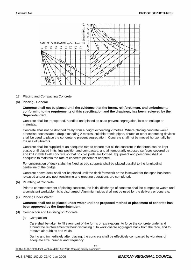
The Contractor shall be responsible for measuring and recording the air temperature, relative humidity, concrete temperature and wind velocity (measured one metre above the as placed concrete) at the point of concrete placement from commencement of placing the concrete and continue until curing has commenced. This information shall be used in conjunction with Figure C340.1 to determine the rate or evaporation of water from the freshly placed and unprotected surface of concrete. The rate of evaporation shall be monitored by the Contractor until such time as curing commences
When the value of the rate of evaporation as determined from Figure C340.1 exceeds 0.50kg/m2 per hour the Contractor shall take precautions such as the application of an aliphatic-alcohol based evaporative retarding compound or controlled fog spray to minimise evaporative moisture losses.
(f) Application of Evaporative Compound
The evaporative retarding compound, when required, is to be applied immediately after initial screeding. The remaining finishing operations can be carried out after application of the compound.
Application of the evaporative retarding compound shall be implemented in accordance with the manufacturer’s instructions.
Figure C340.1 – Evaporation of Water from Freshly Placed Concrete
Contract No. BRIDGE STRUCTURES
© The AUS-SPEC Joint Venture date: Apr 2000 Copying strictly prohibited
17. Placing and Compacting Concrete
(a) Placing - General
Concrete shall not be placed until the evidence that the forms, reinforcement, and embedments conforming to the requirements of this specification and the drawings, has been reviewed by the Superintendent.
Concrete shall be transported, handled and placed so as to prevent segregation, loss or leakage or materials.
Concrete shall not be dropped freely from a height exceeding 2 metres. Where placing concrete would otherwise necessitate a drop exceeding 2 metres, suitable tremie pipes, chutes or other concreting devices shall be used to place the concrete to prevent segregation. Concrete shall not be moved horizontally by the use of vibrators.
Concrete shall be supplied at an adequate rate to ensure that all the concrete in the forms can be kept plastic until placed in its final position and compacted, and all temporarily exposed surfaces covered by and knit in with fresh concrete so that no cold joints are formed. Equipment and personnel shall be adequate to maintain the rate of concrete placement adopted.
For construction of deck slabs the fixed screed supports shall be placed parallel to the longitudinal centreline of the bridge.
Concrete above deck shall not be placed until the deck formwork or the falsework for the span has been released and/or any post-tensioning and grouting operations are completed.
(b) Plumbing of Concrete
Prior to commencement of placing concrete, the initial discharge of concrete shall be pumped to waste until a consistent workable mix is discharged. Aluminium pipes shall not be used for the delivery or concrete.
(c) Placing Under Water
Concrete shall not be placed under water until the proposed method of placement of concrete has been approved by the Superintendent.
(d) Compaction and Finishing of Concrete
(i) Compaction
Care shall be taken to fill every part of the forms or excavations, to force the concrete under and around the reinforcement without displacing it, to work coarse aggregate back from the face, and to remove air bubbles and voids.
During and immediately after placing, the concrete shall be effectively compacted by vibrators of adequate size, number and frequency.
AUS-SPEC-1\QLD-C340 Jan 2009 MACKAY REGIONAL COUNCIL
20

Contract No. BRIDGE STRUCTURES
© The AUS-SPEC Joint Venture date: Apr 2000 Copying strictly prohibited
AUS-SPEC-1\QLD-C340 Jan 2009 MACKAY REGIONAL COUNCIL
21
Vibration shall be applied to the full depth of each layer and extended into the top 100 mm underlying layer. Concrete shall not be vibrated to the point of segregation of the ingredients where internal vibrators are used, they shall be inserted vertically at successive locations at spacings not exceeding the manufacturer’s stated zone of influence and shall not be allowed to rest on the steel reinforcement.
Concrete decks or slabs shall be compacted by immersion vibrators and vibrating screeds.
(ii) Finishing of Exposed Surfaces
Final finishing of exposed concrete surfaces shall be carried out after all bleed water has been removed and the concrete has become sufficiently hard to support the finishing operations. Driers (i.e. dry sand, cement or stone dust) shall not be used to absorb free water.
Finishing of concrete decks or slabs shall be effected with a power trowel fitted with rotating steel floats.
Any drying cracks which appear before or during finishing operations shall be immediately closed with either a wooden or steel float.
Curing shall commence immediately following the progressive completion of final finishing operations.
18. Concrete Casting Sequences
The casting sequence shall be as shown in the drawings or as specified in this specification.
(a) Deck Casting Sequence
The deck casting sequence shall be as shown on the drawings or as specified in this specification. At least seven days shall elapse between the casting of adjacent sections. Unless otherwise shown on the drawings the maximum deck casting length shall be 25 metres.
(b) Box Girder or Voided Slab Casting Sequence
The Contractor shall submit details of his proposed casting sequence and falsework for review by the Superintendent.
Casting sequence details shall include the length of segments, the order of casting and whether segments are to be cast monolithically or in stages. Box girders or voided slabs shall be cast in longitudinal segments with a maximum segment length of 25 metres, unless otherwise shown on the drawings or as specified in this specification. At least seven days shall elapse between the casting of adjacent segments.
Segments incorporating a transverse diaphragm shall be cast monolithically with the full cross section of webs, floor and desk slab extending a distance of at least 5 metres from the face of the diaphragm.
Segments which do not incorporate transverse diaphragms shall be cast monolithically with the full cross section of webs, floor and desk slab, or alternatively may be cast in two stages with a construction joint provided between the webs and the deck slab. If the latter method is adopted, the deck slab shall be cast no later than 14 calendar days after the casting of the webs and floor slab.
19. Construction Joints and Bonding of New Controls
The location and details of construction joints shall be shown on the drawings.
The placing of concrete shall proceed continuously from the joint to joint.
Any point at which the placing of concrete has stopped and the concrete has taken its initial set shall be treated as a construction joint.
Construction joints shall be perpendicular to the principal lines of stress, and in general shall not be located in regions of maximum bending or maximum shear.
Where applicable, concrete in the existing structure shall be broken back as shown on the drawings. Any cracked or damaged concrete remaining after breaking back shall be removed and replaced with new concrete.
Before placing new concrete against concrete which has set, the forms shall be re-tightened.
Concrete against which new concrete is to be placed shall be roughened by removing all laitance and sufficient mortar to expose the coarse aggregate to a depth of 3 mm. the roughened surface shall be cleaned of foreign

Contract No. BRIDGE STRUCTURES
© The AUS-SPEC Joint Venture date: Apr 2000 Copying strictly prohibited
AUS-SPEC-1\QLD-C340 Jan 2009 MACKAY REGIONAL COUNCIL
22
matter, laitance and loose or porous material. The surface shall be thoroughly moistened with water and any excess water removed immediately prior to placing of concrete.
20. Insertions and Greased Joints
Abutting surfaces of concrete shall be separated by grease or other surface coatings or insertions of bituminous impregnated felt or fibreboard as shown on the drawings, so as to prevent the surfaces from bonding or binding together,
Dowels shall be placed as shown on the drawings and prior to placing surrounding concrete.
21. Temperature Differential Limit
The temperature differential across any concrete element shall not exceed 20°C during the period of curing. The Contractor shall demonstrate control of temperature differential to within the specified limit and shall implement special precautions if the temperature differential of 20°C is likely to be exceeded.
22. Curing
(a) General
Curing of concrete shall be carried out using one or a combination of the methods as specified in Clauses C340.5(22)(c), C340.5(22)(d), C340.5(22)(e), C340.5(22)(f), C340.5(22)(g),and C340.5(22)(h).
The curing of exposed concrete surfaces shall commence immediately after finishing operations are progressively completed and shall continue uninterrupted for not less than the periods specified in Table C340.7.
The Contractor shall submit to the Superintendent for review, full details of his proposed methods of curing, as part of his concrete mix design submission, not less than 14 days prior to placement of concrete.
Details submitted shall include the following information for the proposed methods of curing.
(i) Water curing – materials, method and timing of curing;
(ii) Curing Compound – technical specification of the proposed curing compound including the timing, rate of application and method of removal (where required);
(iii) Polyethylene Sheet – material and method of application, sealing and control;
(iv) Maintaining Formwork in Place – timing, method of sealing the formwork and curing exposed surfaces;
(v) Steam or Radiant Heat Curing – full details of control methods and proposed curing cycle.
(b) Period of Curing
The period of curing shall be not less than the number of days given in table C340.7
Table C340.7
Periods of Curing (excluding stream and radiant heat curing)
Periods of Curing
Average Air Temperature During Curing
Concrete Grade
Exposure Classifcation
Type of Cement
10oC to 17oC Above 17oC
GP 7 6 32 A, B1
GB 9 8
GP 6 5 40 B2
GB 8 7
50 C GP 5 5

Contract No. BRIDGE STRUCTURES
© The AUS-SPEC Joint Venture date: Apr 2000 Copying strictly prohibited
AUS-SPEC-1\QLD-C340 Jan 2009 MACKAY REGIONAL COUNCIL
23
55 GB 7 7
For concrete decks and slabs, the periods of curing shall be extended by 2 days.
Notes: 1. Type of cement:
GP – General purpose portland cement.
GB – General purpose blended cement.
2. When the average air temperature during the specified periods of curing falls below 10oC, the periods of curing shall be extended by 2 days.
3. Where a higher concrete is adopted than that shown for a particular exposure classification, the periods of curing for the higher concrete grade may be adopted.
(c) Water Curing
All surfaces of the concrete shall be kept moist for the specified periods of curing by continuous spraying ponding, wet hessian or sand blankets. Wet curing materials used on vertical surfaces shall be effectively wrapped during the whole curing period. The water used shall conform to the requirements of Clause C340.05.
(d) Curing Compound
Curing compounds shall not be used on concrete decks or slabs, unless an aliphatic-alcohol based evaporative retarding compound is also applied after initial screeding in accordance with Clause C340.05(17)(f).
PVA based curing compounds shall not be used.
Curing compounds shall comply with AS 3799. Full details of the curing method shall be submitted to the Superintendent prior to the use of curing compounds, including the time and rate of application, documented evidence of the effectiveness of the compound as a curing agent and method of removal where required. Such compounds shall be pigmented sufficiently to allow visual inspection to ensure full application on the surface. The pigment shall not be visible fourteen days after application. Curing compounds shall not have a deleterious effect on the concrete or stain the surface of the concrete.
The curing compound shall be applied by a pressurised sprayer to give a uniform cover. The sprayer shall incorporate a device for continuous agitation and mixing of the compound in its container during spraying.
The curing compound shall be applied using a fine spray at the rate stated on the certificate of compliance, or at a rate of 0.2 litres/m2 per coat, whichever is the greater. The application rate shall be checked by calculating the amount of curing compound falling on felt mats, each approximately 0.25 m2 in area, placed on the concrete surface.
Two coats shall be applied at the full rate.
The time between the first and second coat shall be in accordance with the manufacturer’s recommendation, or on the basis of a trial application.
Curing compounds shall not be applied to construction joints unless the joint is to be roughened or sandblasted at a later date.
Curing compounds shall not be applied to surfaces which are to be subsequently coated unless they are compatible with the coating, waterproofing or surfacing system or provision is made for removal of the compound from these surfaces prior to the application of the coating, waterproofing or surfacing system.
The curing membranes shall be maintained intact for not less than the specified period of curing. Any damage to the curing membranes during the period of curing shall be repaired immediately at the original rate of application.
(e) Polyethylene Sheet

Contract No. BRIDGE STRUCTURES
© The AUS-SPEC Joint Venture date: Apr 2000 Copying strictly prohibited
AUS-SPEC-1\QLD-C340 Jan 2009 MACKAY REGIONAL COUNCIL
24
Polyethylene sheet shall be of sufficient strength to withstand wind and any imposed foot traffic or physical loading. Torn or punctured sheeting shall not be used. Laps shall be 300 mm minimum and edges and laps shall be sealed by tape or held down by boards or other means. All edges and laps shall be sealed against evaporative moisture losses for the duration of curing.
Polyethylene sheet shall not be used on concrete decks or slabs unless used in conjunction with water curing.
(f) Curing by Maintaining Formwork in Pace
Where formwork is left in place to satisfy the formwork removal times as specified in Clause C340.5(23) where formwork is left in place for the specified period of curing or part thereof, the exposed surfaces of the concrete shall be cured and the formwork shall be sealed against evaporative moisture losses for the duration of curing.
Where formwork is removed prior to the completion of the curing period, curing shall recommence within half an hour and continue until the total curing time is not less that the periods of curing specified in Table C340.7
(g) Steam Curing
(i) General
Method of control, and the proposed curing cycle to achieve the specified concrete compressive strength shall be submitted to the Superintendent. After the initial “maturity” period, units shall be cured in an atmosphere saturated with water vapour at a pressure not exceeding atmospheric pressure.
The Contractor shall take measures to allow for the potential lower 28 day compressive strength obtained from test cylinders initially under in situ Conditions, as compared to these cured in accordance with the requirements of AS 1012.
(ii) Steam Covers
To prevent drying out, steam covers shall be placed over the units immediately following the casting and screeding operations in such a manner as to ensure free circulation of the steam around the concrete mass.
(iii) Curing Cycle
After an initial “maturity” of 40oC hours, but not less than two hours after batching the last batch of concrete for the units, steam shall be admitted to the steam covers at such a controlled rate that the maximum average temperature rise shall not exceed 24oC per hour. (Note: The initial “maturity” period is calculated by dividing 40oC hours by the concrete temperature of the last batch of concrete placed in the unit. The concrete temperature is as measured on an indicating thermometer.) In addition, the temperature rise in any one fifteen minute period shall not exceed 6oC.
If the admission of steam to the steam covers is delayed by more than the initial specified “maturity” of 40oC hours after the completion of placing of concrete, water curing, as specified in Clause C340.5(22)(c) shall be applied until steaming commences.
Steaming shall continue at a rate such that the temperature rise shall not exceed 24oC per hour, until a temperature under the steam covers of not greater than 75oC has been reached, when the steam supply shall be shut down to the point where the temperature is maintained within a range of ±5oC.
After the elapse of sufficient time at the maximum temperature for the required concrete properties to have been reached, steam shall be completely shut down. Steam covers shall not be removed nor any part of the concrete units and test cylinders disturbed or operated upon in any way until the temperature under the steam covers has fallen to within 30oC of the ambient temperature. Also the rate of loss of temperature under the steam covers after shutting off steam shall not exceed 30oC per hour.

Contract No. BRIDGE STRUCTURES
© The AUS-SPEC Joint Venture date: Apr 2000 Copying strictly prohibited
AUS-SPEC-1\QLD-C340 Jan 2009 MACKAY REGIONAL COUNCIL
25
(iv) Temperature Controls
Temperature shall be recorded by means of recording thermometers supplied and installed by the Contractor. These thermometers shall be maintained in good condition and calibration. The temperature sensitive parts of the thermometers shall be so positioned under the steam covers as to cause the thermometers to record the minimum temperature under the covers. One recording thermometer shall be used for each unit or group of unit in line up to a total length of 25 m. For greater lengths, additional recording thermometers shall be used and the distance between the temperature sensitive parts of the thermometers shall not exceed 25 m.
The recording thermometers shall be set in operation immediately upon completion of the casting and screeding, the temperature sensitive part of each thermometer being installed in position at the same time.
Charts shall not be removed from any recording thermometers, nor the recording thermometers disturbed or moved in any way until after the removal of the steam covers.
Charts from temperature recording thermometers shall be retained.
The following information shall be recorded on the chart:
a) date on which steaming commenced;
b) unique identification and description of concrete unit;
c) temperature corrections, if any;
d) time correction, if any;
e) batching of concrete;
f) temperature of concrete when placed;
g) ambient temperature at time of removal of steam covers;
h) name of Contractor or manufacturer.
(v) Steam Delivery
Under no circumstances shall steam jets be allowed to impinge upon any part of the concrete units or of a test specimen, or of their formwork or moulds. Neither shall any steam delivery pipe be attached directly to any formwork or moulds in such a manner as may cause localised overheating of the concrete.
Sufficient steam jets or steam entry points shall be provided to ensure that a substantially uniform temperature is maintained under the steam covers such that the difference in temperature between any two points adjacent to the concrete units is not more than 10oC.
(vi) Extent of Steam Curing
Unless otherwise specified, steam curing shall be continuously applied until at least the 7 day compressive strength for the specified concrete grade is obtained.
(vii) Partial Steam Curing
Where steam curing is used only to obtain sufficient compressive strength for removal of forms or for lifting, curing shall be continued by one of a combination of the methods specified in Clauses C340.5(22)(c), (d) and (e) for a minimum period of 7 days from the time of finishing the concrete.
Where partial steam curing is employed as above, curing shall recommence within half an hour of the cessation of steam curing.

Contract No. BRIDGE STRUCTURES
© The AUS-SPEC Joint Venture date: Apr 2000 Copying strictly prohibited
AUS-SPEC-1\QLD-C340 Jan 2009 MACKAY REGIONAL COUNCIL
26
(viii) Curing of Test Cylinders
Concrete compression test cylinders shall be placed near the concrete units, and shall be so positioned under the steam covers as to be midway between two adjacent points of steam entry, subject always to their being no closer to any points of steam entry than half the width of the concrete units. Test cylinders shall be positioned in a group at the lower face of the concrete unit and shall in no case be placed on top of the concrete unit or its formwork. Test cylinders shall remain in position under the steam covers until the steam curing cycle is complete. Test cylinders shall be suitably covered in such a way as to minimise moisture and temperature losses between the time of removal from the steam covers and the time of forwarding to an accredited laboratory for testing. Cylinders shall be transported in moisture proof containers.
(h) Radiant Heat Curing
(i) General
The application of heat shall be effected by the circulation of hot water which is fed through a series of conduits attached externally to the steel form. A heating box used for the curing of concrete test cylinders shall be connected to hot water heating system.
(ii) Curing Cycle
The curing cycle of the radiant heat curing method shall be in accordance with Clause C340.5(22)(g)(iii) except that reference to steam curing shall be replaced by the application of hot water. The top surface of the finished concrete shall be kept moist throughout the curing cycle.
(iii) Temperature Controls
The water temperature shall be controlled by a thermostat and shall not exceed 75oC. The temperature difference between ingoing and outgoing water shall be maintained at less than 10oC.
Temperature controls shall be in accordance with Clause C340.5(22)(g)(iv), except that reference to steam covers shall be replaced by curing covers. In addition to the specified requirements of Clause C340.5(22)(g)(iv), the Contractor shall also monitor the temperature of the test cylinder heating box by means of a recording thermometer. The difference in temperature between the test cylinder heating box and any point along the hot water heating system shall not exceed 10oC.
(iv) Curing Covers
To prevent drying out, curing covers shall be placed over the units after the top surface of the concrete has taken its initial set and the watering hose has been placed on the concrete.
(v) Extent of Radiant Heat Curing
Unless otherwise specified, radiant heat curing shall be continuously applied until at least the 7 day compressive strength for the specified concrete grade is obtained.
(vi) Curing of Test Cylinders
Concrete test cylinders shall be placed in the heating box which is connected into the mould heating system as soon as the curing starts and shall remain in position until the curing cycle is complete. Test cylinders shall be suitably covered in such a way as to minimise moisture and temperature losses between the time of removal from the heating box and the time of forwarding to an accredited laboratory for testing. Cylinders shall be transported in moisture proof containers.
23. Cracking of Concrete
At the completion of the curing period the concrete shall have no cracks of width greater than 0.10 mm, measured at the concrete surface. Where such cracks exist, they shall be identified as a non-conformance.
24. Removal of Formwork
(a) General
Formwork shall be removed carefully and in such a manner as to avoid damage to the member of the concrete surfaces.
(b) Formwork Removal Times

Contract No. BRIDGE STRUCTURES
© The AUS-SPEC Joint Venture date: Apr 2000 Copying strictly prohibited
AUS-SPEC-1\QLD-C340 Jan 2009 MACKAY REGIONAL COUNCIL
27
Formwork and formwork supports shall remain in position until the times given in Table C340.8 have elapsed, after completion of the placing of concrete.
Table C340.8
Concrete Components Minimum Period before Removal of Formwork and Formwork Supports
Soffits of beams, decks, slabs, cantilevers, diaphragms, crossheads and other structural components
7 days or until such time as the concrete has reached the specified 7 day compressive strength, whichever is greater.
(a) Vertical faces of components when height of each day’s cast is:
(i) Columns – greater than 7 metres;
(ii) Walls – greater than 4 metres.
(b) Load supporting sides of sloping walls of box girders
5 days
(a) Vertical faces of components when height of each day’s cast is:
(i) Columns – greater than 7 metres;
(ii) Walls – greater than 4 metres.
(b) Load supporting sides of sloping walls of box girders
3 days
Vertical faces of components when height of each day’s cast is:
(i) Columns – less than 4 metres;
(ii) Walls – less than 2 metres.
2 days
Sand of slabs and piles 2 day
Where Type GB is used, the times for removal of formwork and formwork supports shall be increased by 1 day. This requirement shall not apply to vertical faces of beams and crossheads, columns and walls when the height of each day’s cast is less than 4 metres or 2 metres respectively, or the sides of slabs and piles.
Where the timing of the removal of formwork and formwork supports is based on compressive strength as given in Table C340.8, test cylinder(s) shall be prepared, cured and tested as specified in Clause C340.5(15). In addition, the curing requirements of Clause C340.5(22) shall apply to the newly exposed surfaces.
25. Surface Finish
(a) General
For any particular class of concrete surface finish, the method of construction and the materials used in the concrete and formwork shall remain consistent and shall be such as to meet the requirements of this specification.
Contractors should note that the standard of surface finish is dependent on the quality of formwork, the compaction of the concrete, and the manner in which the formwork is removed. The higher the standard of surface finish required the greater care will be required to be given to these factors.
The use of mortar topping will not be permitted.
The following surface finishes are specified:
∗ Class 1
∗ Class 2

Contract No. BRIDGE STRUCTURES
© The AUS-SPEC Joint Venture date: Apr 2000 Copying strictly prohibited
AUS-SPEC-1\QLD-C340 Jan 2009 MACKAY REGIONAL COUNCIL
28
∗ Class 3
∗ scabbled
∗ broomed
∗ off-form
Except where other surface finishes are specified on the drawings, surface finishes Class 1, Class 2 and Class 3 shall be used as follows:
(i) Substructure
The back of abutments, wingwalls and piers shall have a Class 1 surface finish. All exposed surfaces of abutments, wing walls & piers from 300 mm below ground level shall have a Class 2 surface finish, except that in cellular structures the faces of wingwalls and ends of piers or walls only shall have a Class 2 surface finish. Upper surfaces of concrete bearing pedestals shall have a Class 2 surface finish.
(ii) Superstructure
The underside of deck between beams shall have a Class 1 surface finish. The faces and undersides of the beams, the edges and the underside of the cantilevered deck slab shall have a Class 2 surface finish. The interior and exterior faces of kerbs and the upper surfaces of the kerbs shall have a Class 3 surface finish.
For box girder bridges, the inside surface of box girder webs, floor and deck have a Class 1 surface finish. All external surface of the box girder and voided slab shall have a Class 2 surface finish.
(iii) Above Deck Surface
All surfaces above the tops of kerbs shall have a Class 3 surface finish. End posts shall have a Class 3 surface finish. Precast parapet units and associated cast-in-place concrete shall have a Class 3 surface finish.
(iv) Precast Concrete
Precast crown units shall have a Class 2 surface finish.
Precast parapet units shall have a Class 3 surface finish.
Precast piles shall have a Class 1 surface finish.
Precast components other than crown units and parapet units shall have a Class 2 surface finish.
(b) Rejection of Surfaces Finishes
Any concrete surface that does not comply with the requirements of this specification shall be subject to the following alternatives:
(i) rejection of the concrete, in which case the concrete shall be demolished and replaced;
(ii) acceptance of the defective concrete surface will be withheld subject to remedial measures being carried out.
(c) Class 1 Surface Finish
For a class 1 surface finish no defects which structurally affect the concrete or reduce the cover to the steel reinforcement will be permitted. All mortar fins shall be tooled away to expose a surface of dense sound concrete. Bolts, wires and other embedments shall be set back to the minimum clear cover specified and the ends filled with shrinkage compensating mortar. Concrete spacer blocks shall be manufactured with concrete of the same mixture as the parent concrete in the structure.
(d) Class 2 Surface Finish
A Class 2 surface finish shall achieve a concrete surface of uniform colour and free from any major surface defects. The design of the formwork shall be such as to give a deflection under the loads imposed on it of not more than 3 mm between studs or frame supports. The formwork shall be constructed so as to prevent water run off carrying stains on to previously cast concrete surfaces. The finished concrete surface shall be protected from mortar slurry, physical damage, spillage and water borne staining. Steel shall be protected

Contract No. BRIDGE STRUCTURES
© The AUS-SPEC Joint Venture date: Apr 2000 Copying strictly prohibited
to prevent rust staining of the concrete surface. No defect which structurally affects the concrete or reduces the cover to the steel reinforcement or other embedded components will be permitted.
(e) Class 3 Surface Finish
A Class 3 surface finish shall achieve a concrete surface of uniform colour and texture and free from surface defects. The design of the formwork shall be such as to give a deflection under the loads imposed on it of not more than the following:
1.5 mm between adjacent framing members
3 mm over the vertical face for the full depth of a panel, or height of a lift, whichever is the lesser
3 mm over a 3 m length horizontally.
(f) Scabbled Finish
Scabbling shall be remove all laitance and loose or porous material without leaving excessive depressions. Exposed aggregate shall be firmly embedded in the concrete.
(g) Broomed Finish
Unless otherwise stated on the drawings, all deck and approach slab surfaces shall have a coarse broomed finish. The direction of brooming shall be at right angles to the bridge centre line.
26. Tolerances
(a) General
The tolerances listed in tables C340.9, C340.10, C340.11 and C340.12 are the allowable deviations from the dimensions shown on the drawings. These tolerances will be a basis for acceptance of the work.
(b) Soffits
The soffits of arched, box girders, beams and deck edges shall be continuous curves or straight lines as shown on the drawings, free from all visible irregularities.
Table C340.09 – General Tolerances
Item Tolerance (mm)
Placing of reinforcement
Placing of post-tensioning sheathing
Concrete cover
5
5
0 to +5
Table C340.10 – Cast In Situ Concrete
AUS-SPEC-1\QLD-C340 Jan 2009 MACKAY REGIONAL COUNCIL
29
Item Tolerance
(mm unless shown otherwise)
(i) Footings ∗ Plan dimensions - Formed footings and pile caps
- Unformed footings (when approved by the Superintendent)
∗ Thickness - < 300 mm - > 300 mm ∗ Top of footing or pile cap reduced level ∗ Departure from the plan position in any direction
-15 to +15 0 to +150
-5 to +25
-10 to +50 -25 to +25
50 (ii) Cylinders
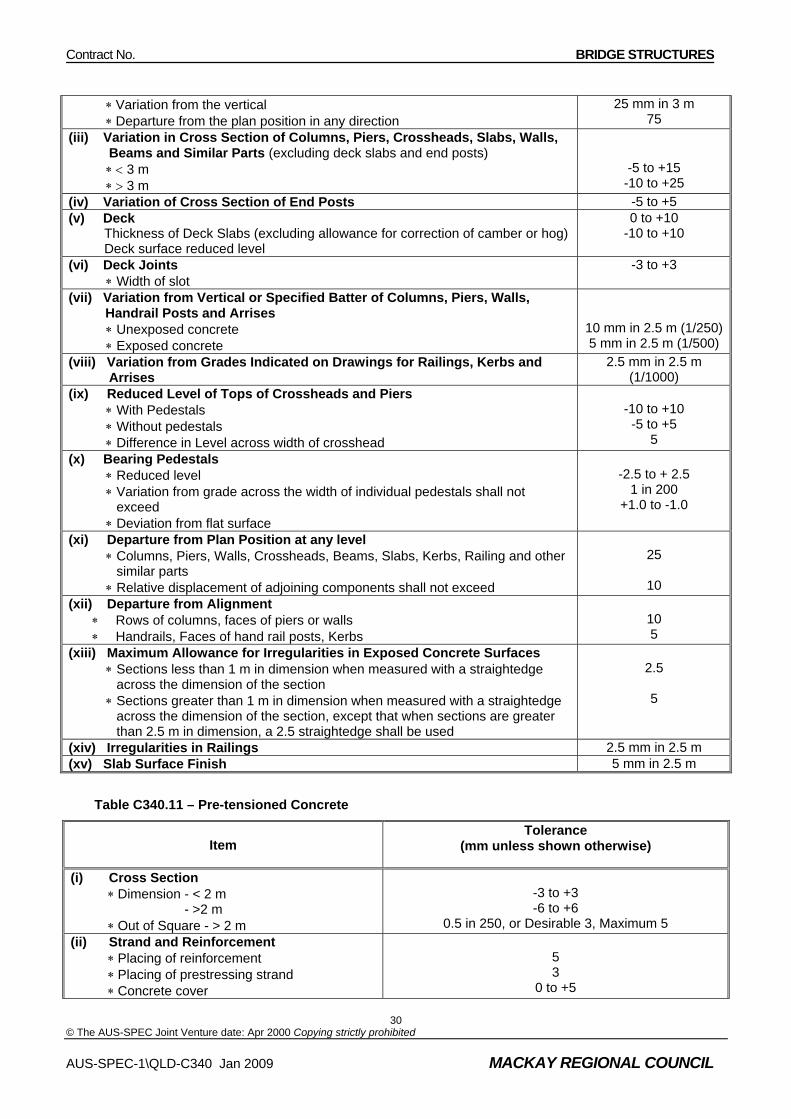
Contract No. BRIDGE STRUCTURES
© The AUS-SPEC Joint Venture date: Apr 2000 Copying strictly prohibited
AUS-SPEC-1\QLD-C340 Jan 2009 MACKAY REGIONAL COUNCIL
30
∗ Variation from the vertical ∗ Departure from the plan position in any direction
25 mm in 3 m 75
(iii) Variation in Cross Section of Columns, Piers, Crossheads, Slabs, Walls, Beams and Similar Parts (excluding deck slabs and end posts)
∗ < 3 m ∗ > 3 m
-5 to +15 -10 to +25
(iv) Variation of Cross Section of End Posts -5 to +5 (v) Deck
Thickness of Deck Slabs (excluding allowance for correction of camber or hog) Deck surface reduced level
0 to +10 -10 to +10
(vi) Deck Joints ∗ Width of slot
-3 to +3
(vii) Variation from Vertical or Specified Batter of Columns, Piers, Walls, Handrail Posts and Arrises
∗ Unexposed concrete ∗ Exposed concrete
10 mm in 2.5 m (1/250)5 mm in 2.5 m (1/500)
(viii) Variation from Grades Indicated on Drawings for Railings, Kerbs and Arrises
2.5 mm in 2.5 m (1/1000)
(ix) Reduced Level of Tops of Crossheads and Piers ∗ With Pedestals ∗ Without pedestals ∗ Difference in Level across width of crosshead
-10 to +10
-5 to +5 5
(x) Bearing Pedestals ∗ Reduced level ∗ Variation from grade across the width of individual pedestals shall not
exceed ∗ Deviation from flat surface
-2.5 to + 2.5
1 in 200 +1.0 to -1.0
(xi) Departure from Plan Position at any level ∗ Columns, Piers, Walls, Crossheads, Beams, Slabs, Kerbs, Railing and other
similar parts ∗ Relative displacement of adjoining components shall not exceed
25
10
(xii) Departure from Alignment ∗ Rows of columns, faces of piers or walls ∗ Handrails, Faces of hand rail posts, Kerbs
10 5
(xiii) Maximum Allowance for Irregularities in Exposed Concrete Surfaces ∗ Sections less than 1 m in dimension when measured with a straightedge
across the dimension of the section ∗ Sections greater than 1 m in dimension when measured with a straightedge
across the dimension of the section, except that when sections are greater than 2.5 m in dimension, a 2.5 straightedge shall be used
2.5
5
(xiv) Irregularities in Railings 2.5 mm in 2.5 m (xv) Slab Surface Finish 5 mm in 2.5 m
Table C340.11 – Pre-tensioned Concrete
Item Tolerance
(mm unless shown otherwise)
(i) Cross Section ∗ Dimension - < 2 m
- >2 m ∗ Out of Square - > 2 m
-3 to +3 -6 to +6
0.5 in 250, or Desirable 3, Maximum 5 (ii) Strand and Reinforcement
∗ Placing of reinforcement ∗ Placing of prestressing strand ∗ Concrete cover
5 3
0 to +5

Contract No. BRIDGE STRUCTURES
© The AUS-SPEC Joint Venture date: Apr 2000 Copying strictly prohibited
AUS-SPEC-1\QLD-C340 Jan 2009 MACKAY REGIONAL COUNCIL
31
(iii) Squareness of Ends
∗ Dimension - < 500 mm ∗ - > 500 mm
Deviation from a plane perpendicular to the longitudinal axis of a member, of from the specified end plane:
3 mm 6 mm per metre (10 mm maximum)
(iv) Length ∗ Diagonal length for precast unit ∗ Overall length or length centre of bearings
(for beams and slabs) ∗ Centre to centre spacing of holes for
transverse rods or both
5
0.06% x specified length (max 20)
5
(v) Profile in a Vertical Plane (Hog) The deviation in hog of any unit from the mean hog of all units shall not vary by more than 0.07% of the length of the units. The absolute value for hog for any unit shall not be less than zero. Hog measures shall be made at transfer of prestress.
(vi) Profile in a Horizontal Plane (Bow) The deviation of a unit from the required profile shall not exceed 0.06% of the length of the unit or a maximum of 15 mm.
(vii) Twist The angular rotation of any cross section relative to an end cross section shall not exceed 1 in 200.
(viii) Sole Plates The plane of the sole plate or bearing surface shall not vary from that shown on the drawings by more than 1 in 200 in any direction.
(ix) Deviation ∗ The distance of any point from a flat plane
held against that surface.
3 mm in 2 m
Table C340.12 – Precast Concrete Units
Item Tolerance
(mm unless shown otherwise)
(i) General ∗ Placing of reinforcement ∗ Placing of sheathings for post-tensioned
segmental components ∗ Concrete cover
5 5
0 to +5 (ii) Cross Section
∗ Dimension - < 2 m - >2 m
∗ Out of Square
0 to +3 0 to +6
Maximum 5
(iii) Squareness of Ends
∗ Dimension - < 500 mm ∗ - > 500 mm
Deviation from a plane perpendicular to the longitudinal axis of a member, of from the specified end plane:
3 mm 6 mm per metre (10 mm maximum)
For parapet units and new jersey barriers, the deviation from a place perpendicular to the longitudinal axis shall not exceed 3 mm.
(iv) Length ∗ Diagonal length for precast unit ∗ Overall length or length centre of
bearings (for beams and slabs) ∗ Centre to centre spacing of holes for
transverse rods or bolts ∗ Overall length for parapets and new
jersey barriers
5
0.06% x specified length (max 20)
5
3
(v) Profile in a Vertical Plane (Camber) The deviation of a unit from the design camber, after

Contract No. BRIDGE STRUCTURES
© The AUS-SPEC Joint Venture date: Apr 2000 Copying strictly prohibited
AUS-SPEC-1\QLD-C340 Jan 2009 MACKAY REGIONAL COUNCIL
32
allowance has been made for the deflection due to the mass of the member, shall not exceed 0.10% of the length of the unit with a maximum of 6 mm. Measurement of camber shall be made at the mid-point of the member which shall be supported at the bearing positions.
(vi) Profile in a Horizontal Plane (Bow) The deviation of a unit from the required profile shall not exceed 6 mm or 0.10% of the length of the unit, whichever is the greater. Bow in precast parapet units and new jersey barriers shall not exceed 3 mm.
C340.06 STEEL REINFORCEMENT
1. General
this section covers the supply, handling and placing of steel reinforcement for concrete.
2. Standards
Unless shown otherwise on the drawings, reinforcement shall consist of deformed high strength steel reinforcing bars complying with the requirements of AS 4671 “Steel Reinforcing Materials”, Grade 400Y.
3. Reinforcement Supply
The Contractor shall be responsible for the preparation of the reinforcement schedule for all reinforcement required for the contract.
The Contractor shall make appropriate allowances when preparing his reinforcement schedule to achieve the specified tolerances on member dimensions, concrete cover and location of reinforcement and any post-tensioning sheathing or other fitments, taking into account the practical variations in the tolerances noted and other margins normally applied by reinforcement suppliers.
Two copiers of the reinforcement schedule shall be supplied to the Superintendent at least two weeks prior to the scheduled date for cutting and bending of the reinforcement.
Steel reinforcement shall be supplied cut to length, bent to shape, free from loose mill scale, loose or thick rust, or any other coating.
4. Testing
(a) General
Steel reinforcement supplied by the Contractor shall be tested for conformity with the specified requirements before being accepted for use in the works of this contract. Testing of steel reinforcement shall be carried out in accordance with the appropriate Australian Standard, by officers experienced in the test methods described in the Contract, in a laboratory accredited by the National Association of Testing Authorities (NATA) for those test methods. All tests shall be endorsed in accordance with the NATA registration for that laboratory.
(b) Sampling
For Grade 400Y bars, at least one sample shall be tested for each 3 T reinforcement supplied. Alternatively where the Contractor established to the satisfaction of the Superintendent that steel reinforcement is of Australian manufacture, at least one sample of each size of bar to be used in the works shall be tested. Where the use of other reinforcement grades is indicated on the drawings, one sample shall be taken from each bar size for each consignment.
(c) Failures
Should any test piece fail to satisfy the requirements of the appropriate standard concerning ultimate tensile strength, minimum yield stress, minimum elongation or bending properties, all reinforcement represented by that sample shall not be used in the works.
5. Bending
Bars shall be bent cold, and shall not be bent or straightened in a manner that will cause damage to the bars.

Contract No. BRIDGE STRUCTURES
© The AUS-SPEC Joint Venture date: Apr 2000 Copying strictly prohibited
AUS-SPEC-1\QLD-C340 Jan 2009 MACKAY REGIONAL COUNCIL
33
Bars with kinks or bends not shown on the drawings or in the reinforcement schedule shall not be used.
Heating of reinforcement will not be permitted.
6. Rebending on Site
Any re-bending of steel reinforcement shall not commence until a procedure has been approved by the Superintendent.
7. Identification
Reinforcement and fabric shall be bundled and tagged for easy identification.
8. Handling and Storage
Care shall be taken that reinforcement is not damaged, kinked or bent, and bars so impaired shall not be used in the works.
Reinforcement shall be kept free from loose or thick rust, oil, grease, tar, paint, mud or any other deleterious substance.
The Contractor shall take such steps as are considered necessary to prevent excessive rusting of the reinforcement.
9. Placing
All reinforcement shall be securely held during the depositing and compacting of the concrete. Reinforcement supports shall be made of durable materials strong enough to withstand the imposed loads without movement of the reinforcement. They shall be positively attached to the reinforcement and of such size as to maintain the specified cover.
Tack welding of reinforcement will be permitted for Grade 250R and Grade 400Y steel bars provided it is not within 50 mm of the tangent point of any bend in the steel and provided it is in accordance with AS 1554 part 3.
Metal and plastic coated metal supports which extend to the surface of the concrete and wooden supports shall not be used. Placing bars on layers of fresh concrete as the work progresses and adjusting bars during the placing of concrete will not be permitted.
Tie wire shall have the minimum concrete cover specified.
Before concrete is placed, the reinforcement to be embedded shall be free of mortar, oil, dirt, loose mill scale, heavy or scaly rust, grease, paint, tar or any other coating which may destroy or reduce bond between the reinforcement and concrete.
Thin powdery rust and tightly adhering rust are not considered detrimental, and need not be removed. Rust which pits the surface of the reinforcement may be a cause for rejection. Mill Scale which flakes off when the reinforcement is struck by a hammer or which can be readily dislodged by hand wire brushing, shall be removed.
10. Splicing
Where practicable, all reinforcement shall be supplied in the full lengths shown on the drawings. Where bars are not so supplied, the Contractor shall splice the bars by lapping where directed or as shown on the drawings. In lapped splices, the bars shall be placed in contact and wired together in such a manner as to maintain a clearance to the surface of the concrete of not less than the cover specified. The lap shall be long enough to develop the full strength of the bar and unless shown in the drawings shall be not less than the number of diameters shown in the following table:
Bars in Tension Bar Type and Splice Location Grade 250R or Grade
250 Hard Drawn Wire or
Grade 400Y
A. Plain Bar
(i) plain bars other than as in (ii) and (iii) below
(ii) top bars (see Note 2 below)
(iii) two-way footings
40 D
64D
52D
54 D
86 D
72 D

Contract No. BRIDGE STRUCTURES
© The AUS-SPEC Joint Venture date: Apr 2000 Copying strictly prohibited
AUS-SPEC-1\QLD-C340 Jan 2009 MACKAY REGIONAL COUNCIL
34
B. Deformed Bar
(iv) deformed bars other than as in (v) and (vi) below
(v) top bars (see Note 2 below)
(vi) two-way footings
-
-
-
36 D
42 D
38 D
Notes: 1. D is the diameter of the smaller steel reinforcing bar.
2. Top bars are horizontal bars with more than 300 mm of concrete below.
3. Splice lengths shall be increased by multiplying by 1.33 where bars are spliced at locations of maximum stress or where more than half the bars are spliced at any one location.
4. For bars in compression, the splice lengths may be reduced by multiplying by the factor (allowable compressive stress/allowable tensile stress).
5. Splice lengths shall be increased by multiplying by the factor (bar diameter)/32 where the bar diameter is larger than 32 mm.
Where possible, reinforcement shall not be spliced at points of maximum stress and not more than 50% the total area of tensile reinforcement shall be spliced at any one section.
11. Projecting Reinforcement
Where shown on the drawings, steel reinforcement shall be left projecting for the purpose of bonding on subsequent work. Care shall be taken to avoid damage to the bars after they have been set and any damage to the bars or their setting shall be repaired by the Contractor.
12. Welded Splices in Reinforcement
Reinforcement shall be spliced by welding only at the locations shown on the drawings.
Welding shall not commence until the welding procedure has been qualified and reviewed by the Superintendent. (Hold Point)
The qualification process shall be in accordance with AS 1554, Part 3.
Welding procedure testing is not required for tack welding.
The reinforcement projecting from the ends of beams shall be spliced as shown in the drawings.
Pairs of bars with misalignments less than 8 mm may be realigned prior to welding. Splices for pairs of bars with misalignments greater than 8 mm shall be packed prior to welding.
Welding of continuity bar reinforcement shall not commence until the welding procedure has been qualified and reviewed by the Superintendent. (Hold Point)
The qualification process shall be in accordance with AS 1554, Part 1 and with the following additional requirements:
(a) Production of a weld test plate, witnessed by the Superintendent. Seven (7) days notice is required by the Superintendent prior to the production of the test plate.
(b) Submission to the Superintendent of test certificates demonstrating compliance of the procedure with As 1554, Part 1.
The welding procedure shall provide a weld with the specified throat thickness, free from inclusions and imperfections, and with satisfactory fusion and surface appearance.
Care shall be taken during welding to avoid excessive heating of the reinforcing bar.
The earth lead shall be attached to the steelwork being welded at all times to prevent leakage of currents.
C340.07 FORMWORK (CAST-IN-SITU CONCRETE)

Contract No. BRIDGE STRUCTURES
© The AUS-SPEC Joint Venture date: Apr 2000 Copying strictly prohibited
AUS-SPEC-1\QLD-C340 Jan 2009 MACKAY REGIONAL COUNCIL
35
1. General
the formwork shall be constructed so as to produce the finished concrete to the shape, lines and dimensions shown on the drawings, and in accordance with the finishes and tolerances specified in Section C340.05 “Structural Concrete”.
2. Formwork Design
Formwork shall be rigid, watertight, braced and tied together so as to maintain position and shape during all construction activities, and shall be constructed in such a way that it can be removed without damage to the concrete.
The Contractor shall submit detailed plans and calculations of the proposed formwork to the Superintendent prior to commencement of formwork construction. These plans shall include all details of formwork, formwork joints, sealing procedures, ties, size and spacing of framing and details of any proprietary fittings or systems proposed to be used, and shall comply with AS 3610 “Formwork for Concrete”. The requirements of the Scaffolding Regulations shall be observed with respect of all formwork.
3. Formwork Materials
The type and condition of formwork sheeting and lining, and the ability of the formwork and its supports to withstand distortion caused by the placement and compaction of the concrete, and the standard of workmanship used in the formwork construction shall be such that the finished surfaces of the concrete will conform to the requirements of the specifications and drawings.
Formwork shall be so constructed and of sufficient stiffness to tolerate high frequency vibration and shall be of uniform stiffness to avoid causing varying vibration amplitudes over the formwork surfaces during compaction of the concrete.
Fillets and chamfers shall be provided at re-entrant angles and corners. They shall be 20 mm by 20 mm unless otherwise shown on the drawings.
4. Formwork Construction
The use of wires or bolts extended to the surface of the concrete will not be permitted except where shown on the drawings. Any embedded ties shall remain embedded and shall terminate not less than the minimum clear cover specified on the drawings. All recesses shall be filled with a shrinkage compensating mortar.
Errors in line or level of the formwork, or positioning and/or quantity of steel reinforcement shall be corrected prior to placing concrete. The Contractor will be responsible for any defects to the framework, reinforcement, embedded components, or the formed concrete surface, which may become apparent during or after casting the concrete.
Formwork shall not be placed in locations where steel reinforcement and other fixtures cannot be inspected, until such time that the evidence that the reinforcement and other fixtures conform to the requirements of the specifications and the drawings has been obtained and recorded by the Contractor.
5. Removal of Formwork
Time of removal of formwork and formwork supports shall be specified in Section C340.05.
6. Void Formers
The void formers shall be made watertight to prevent ingress of concrete slurry and strong enough to withstand the placing and compaction of the concrete without suffering damage or deformation.
Notwithstanding the tolerances specified in C340.05 the out of round of voids formed by cylindrical formers, calculated from diameters measured at right angles shall not exceed 20 mm at any point.
The void former shall be securely restrained in position during casting. Large uplift forces acting as a result if the buoyancy effect and any lateral pressure due to concrete placement shall be resisted by external means and not by securing the void former to the steel reinforcement.
C340.08 PRECAST CONCRETE UNITS
1. General
This section covers the manufacture, storage, handling and delivery of precast concrete units.

Contract No. BRIDGE STRUCTURES
© The AUS-SPEC Joint Venture date: Apr 2000 Copying strictly prohibited
AUS-SPEC-1\QLD-C340 Jan 2009 MACKAY REGIONAL COUNCIL
36
Concrete for these units shall be in accordance with C340.05 “Structural Concrete” and reinforcement shall be in accordance with C340.06 “Steel Reinforcement”.
2. Forms
Forms shall be manufactured from steel, except where otherwise approved by the Superintendent.
The formwork shall be constructed so as to produce the finished concrete to the shape, lines and dimensions shown on the drawings, and in accordance with the surface finish and tolerances specified on C340.05 “Structural Concrete”.
Void formers shall be securely restrained in position vertically against the action of placing concrete and subsequent flotation under vibration. The void former shall likewise be laterally restrained against forces arising from different pressures during placing of concrete.
The use of wires or bolts extended to the surface of the concrete will not be permitted expect where shown on the drawings. Any embedded ties shall remain embedded and shall be terminate not less than the specified concrete cover. All recesses shall be filled in accordance with the surface finish provisions of Sectio C340.05.
3. Removal of Units From Forms
Unless otherwise specified, the minimum concrete compressive strength for removal of units from forms shall be 20 Mpa.
4. Projecting Reinforcement
Where shown on the drawings, steel reinforcement shall be left projecting for the purpose of bonding on subsequent work. Care shall be taken to avoid disturbing the bars during the specified period for curing of the concrete. Projecting reinforcement which has been damaged or dislodged or which is loose in the concrete will be cause for rejecting of the units.
Continuity bars shall be positioned within 3 mm of the positions shown on the drawings. The relative deviation of any two bars cross sections, taken at right angles to the longitudinal centreline of the unit over the projecting length of bar, shall be within 3 mm.
5. Marking
The identification number and date of casting shall be marked on every precast unit.
Temporary identification shall be made on the top surface of the unit near an end, except for parapet units. Final markings shall be made by indelible marking material, using letters approximately 40 mm high.
For parapet units, temporary identification shall be made on the broomed surface of the parapet as shown on the drawings. Final markings shall be made on one end of each unit.
Piles shall be marked and numbered at 500 mm increments starting from the toe with an indelible marking material.
6. Handling and Storage
Units shall not be stored in areas subject to flooding.
Units shall not be stored within 10 m of existing or proposed overhead power or telephone lines, or over service conduits, drainage pipes or uncompacted fill.
The units shall be supported on bearers clear of the ground. Bearers shall support the units over their full width and be placed perpendicular to the longitudinal axis of the unit. Unless specified otherwise, bearers shall be placed beneath the specified lifting points clear of any sole plates. The ground or space between the bearers supporting the units shall be carefully cleared and levelled so as to prevent the unit from being supported other than on the bearers. The bearers shall rest on a firm foundation, and adequate precautions shall be taken to prevent subsidence.
Where the method of handling and supporting is not specified, the Contractor shall submit, for review by the Superintendent, details of his proposals 14 days prior to lifting and supporting the units.
Unless otherwise specified, precast units shall be lifted and supported with the top surface uppermost at all times. The angle subtended by the slings and the longitudinal axis of the unit shall be not less than 60o.
Beams shall be stored and handled with webs vertical at all times.
Contract No. BRIDGE STRUCTURES
© The AUS-SPEC Joint Venture date: Apr 2000 Copying strictly prohibited
AUS-SPEC-1\QLD-C340 Jan 2009 MACKAY REGIONAL COUNCIL
37
All beams shall be laterally supported. The lateral bracing shall be designed for 10% of the dead load of the beam at the mid height of the beam.
Beams and parapet units shall not be stored in stacks.
Slabs, planks and piles may be stored in separate stacks of identical units up to a maximum height of 2 m, or two units high, whichever is greater. Crown units may be stored in separate stacks of identical units up to a maximum height of 3 m. the upper layers shall be separated from the lower layers by suitable timber bearers in line vertically at the specified supporting points.
7. Transporting
Units shall not be transported from the precast yard until specified 28 day concrete compressive strength has been achieved, and not before 7 days after casting.
Units shall be securely fixed to the transporter and provision shall be made to protect the units from damage caused by lashings.
During transport of beam units the Contractor shall provide end bracing and, if necessary, top flange bracing. Bearings and supports shall allow for longitudinal rotation of the unit in transport and have adequate width and bearing capacity.
No beam shall be transported and erected if it has a bow in excess of 1 in 400 of the length or 75 mm whichever is the lesser. Should the bow at any time exceed the maximum allowable limit steps shall be taken to ensure the safety of the unit throughout the journey.
8. Erection of Prestressed and Reinforced Concrete Beams
Precast units shall not be placed in position less than 14 days after casting crossheads nor before the concrete has attained a strength of not less than 80% of the specified 28 day concrete compressive strength for the crossheads concrete strength grade as shown on the drawings. Beams shall not be placed until at least 7 days after pedestals have been cast. Where fixed bearings are specified beams shall not be placed until at least 14 days after fixing the dowels. Beams shall be placed so that anchor dowels at fixed bearings are engaged in the holes provided in the sole plates of beams.
When beams are placed in a temporary or final position they shall be braced to prevent overturning.
Should a Contractor desire to place slabs using construction equipment operating from a previously placed span of slabs, the written approval of the Superintendent shall be obtained.
9. Traceability of Precast Concrete Units
All manufactured precast concrete units shall be traced from the completion of manufacture to their final location by a unique identification number.
C340.09 FABRICATION OF STEELWORK
1. General
This section covers the fabrication and erection of steelwork.
2. Material Compliance and Traceability
The Contractor shall submit to the Superintendent a Certificate of Compliance and related test certificates. The test certificates shall be related to the steel by trade marks and heat number.
All steel incorporated into the works shall be identified in accordance with the marking requirements as specified in AS 594, AS 3678 or AS 3679 and it shall be traced from the point of manufacture to its final location in the structure.
Unidentified steel shall not be used in the works.
3. Storage of Materials
All steel whether fabricated or not, shall be stored above the ground and adequately protected against corrosion.
4. Straightening of Forming Material and Components
the methods used to straighten or form materials shall not reduce the properties of those materials below the minimum property values as specified in the relevant Australian Standards.

Contract No. BRIDGE STRUCTURES
© The AUS-SPEC Joint Venture date: Apr 2000 Copying strictly prohibited
AUS-SPEC-1\QLD-C340 Jan 2009 MACKAY REGIONAL COUNCIL
38
5. Cutting
Cutting shall be carried out by methods that will not be detrimental to the finished product.
Shearing or cropping shall not be used for main plates, reinforcing plates, main gussets, splice plates rolled sections and shapes or any steel thicker than 12 mm. Distortions caused by shearing shall be removed.
Flame cutting procedures for tension members shall be such that the heat affected hardness along the cut edges shall not exceed 350 h.v. (Vickers Hardness Number).
Unless otherwise shown on the drawings all plates shall be finished square, straight and plane without burrs or imperfections.
The roughness of the cut surface shall not be greater than the following:
(a) Normal Applications
As cut or minor dressing only – Maximum roughness 25 μm (CLA)
(b) Fatigue Applications
As specified on the drawings – Maximum roughness type A 12 μm (CLA)
Maximum roughness type B 25 μm (CLA)
(c) Welds
Incorporated in welds - to comply with requirements of AS 1554.
NOTES:
(1) Roughness values may be estimated by comparison with surfacer replicas, such as the AWRA Flame Cut Surface replicas.
(2) Suitable techniques of flame cutting are given in AWRA Technical Note 5.
(3) CLA = Centre Line Average Method.
Cut surface roughness exceeding these values shall be repaired by grinding to give a value less than the specified roughness. Grinding marks shall be parallel to the direction of the cut.
Where steel work is to be coated all arris edges shall be ground or machined to a smooth even surface finish with a radius of approximately 2 mm. Rolled edges need not be ground provided that the corners are rounded and that the edges are square and straight.
All re-entrant corners shall have a radius of not less then 20 mm.
Notches and gouges not closer than 20 times the thickness of the component and not exceeding 1% of the total surface area on an otherwise satisfactory surface are acceptable, provided that imperfections greater than 0.2 times the thickness of the component but not exceeding 2 mm are removed by machining or grinding. The depression shall be tapered out smoothly for a distance of at least 75 mm on both sides of the defect. The finished product shall be within the specified tolerances.
Any steel having striations or gouges with a depth of 2 mm or greater shall be repaired in accordance with AS 1554 Part 1 or Part 5 as required.
6. Holing
Holes may be either drilled full size or reamed to full size after sub-drilling or sub-punching. Sub-drilled or sub-punched holes shall be at least 3 mm undersize.
Flame cutting of holes shall not be permitted.
Punching of holes to full size will not be permitted for any grade of steel. Sub-punching will only be permitted in grade 250 steel and only in material less than 20mm in thickness. Sub-punching will not be permitted for grade 250 L15 or for any higher grade of steel.
All holes shall be cylindrical and perpendicular to the face of the member. The nominal diameter of a competed hole other than a hole in a base plate shall be 2 mm larger than the nominal bolt diameter for a bolt not exceeding 24 mm in diameter, and not more than 3 mm larger for a bolt of greater diameter.

Contract No. BRIDGE STRUCTURES
© The AUS-SPEC Joint Venture date: Apr 2000 Copying strictly prohibited
AUS-SPEC-1\QLD-C340 Jan 2009 MACKAY REGIONAL COUNCIL
39
All holes shall be located with an accuracy such that after the holes have been reamed or drilled, 85% of the holes in any contiguous group shall show no offset greater than 1 mm between adjacent thickness of metal.
Drifting to enlarge holes shall not be allowed.
7. Welding Procedure Qualification
For the purpose of qualification, welding procedures include welding procedures resulting from flame cutting, the welds detailed on the drawings, weld joining sub lengths of material, stud shear connector welding and tack welding.
Unless otherwise specified in the Contract Documents all welding procedures shall be qualified as follows:
(a) flange butt welds, field splice welds, web to flange welds and all tack welds for these joints – method (d) of Cause 4.2 of AS 1554 Part 1 or Part 5 as applicable;
(b) all other welds – Clause 4.2 of AS 1554 Part 1 or Part 5 as applicable.
Production of welded test plates, as required to obtain documentary evidence for procedural approval, shall be witnessed by the Superintendent. The Superintendent requires seven (7) days notice prior to the production of the weld test plates.
Tests shall be carried out in accordance with the relevant Australian Standard as detailed in Table C340.13. These tests shall be performed on test pieces cut from a weld test plate of the full section under consideration and with a minimum length of 300 millimetres, except for any web to flange connection where the test piece shall be cut from a welded test plate of minimum length of 2000 millimetres.
Table C340.13
Weld Test Requirement
Flange butt welds, Web flange connections and Field splice butt welds
One weld macro test AS 1554 Part 1 or 5 Clause 4.6.5
Flange butt welds, Web flange connection (T but welds) and Field splice butt welds
One weld joint tensile test AS 1554 Part 1 or 5 Clause 4.6.6
Flange butt welds and Field splice butt welds
Two side bend tests, or one face and one root bend test
AS 1554 Part 1 or 5 Clause 4.6.7
(For L15 Steels) Flange butt welds and Field splice butt welds
One set of 3 Charpy impact tests AS 1554 Part 1 or 5 Clause 4.6.8
Flange butt welds and Field splice butt welds
One hardness test – Heat affected zone
AS 1554 Part 1 or 5 Clause 4.6.10
Web flange connections One set of 3 fillet break tests AS 2205 Part 4.2 and As 1554 Part 1 or 5 Table 6.2
Documentary evidence of the results of testing for each of the weld procedures shall be submitted to the Superintendent for review 2 working days prior to commencement of welding.
A photograph of the etched surface of all weld macro-tests, at a magnification of x1 or greater shall be submitted to the Superintendent with the test results.
8. Welding
Welders shall be suitably qualified to carry out the welding procedures on which they will be employed.
All welding consumables shall be stored, handled and used in accordance with AS 1554.
Electrodes shall be used in accordance with the recommendation of the manufacturer.
Preparation, assembly, preheating and welding shall be carried out in strict accordance with the relevant sections of AS 1554, Part 1 or Part 5, as specified, and in accordance with the following additional requirements.

Contract No. BRIDGE STRUCTURES
© The AUS-SPEC Joint Venture date: Apr 2000 Copying strictly prohibited
AUS-SPEC-1\QLD-C340 Jan 2009 MACKAY REGIONAL COUNCIL
40
(a) Low hydrogen electrodes shall be used for all manual metal arc butt welds.
(b) Minimum length of tack weld shall be 50 mm for a 5 mm fillet weld or 80 mm for a 4 mm fillet weld.
(c) Suitable run-on and run-ff tabs shall be used for all butt welds and web to flange fillet welds. Each weld pass should be terminated on the run-on/run-off tabs at least 20 mm beyond the edge of the parts to be joined.
(d) Root runs of double sided butt welds shall be back-gouged sufficient to ensure full penetration.
(e) The maximum size of electrode for down hand position welding, expecting root runs of multiple pass welds, shall be 6 mm unless the work is in the first (natural-vee) position where 8 mm electrodes may be used. For welds made in all other positions and the root runs of multiple pass welds, the maximum size shall be 5 mm.
(f) The maximum size of fillet weld which may be made in one pass shall be 8 mm,. except that 10 mm fillet welds may be made in the flat (natural-vee) position.
(g) A single layer of weld metal, whether deposited in one pass or made up of several parallel beads, shall not exceed 4 mm in thickness except that the bead at the root may be 6 mm in thickness if the position of welding and viscosity of the weld metal is such that it does not overflow onto unfused parent metal.
(h) When welding in the vertical position the direction of welding for all passes shall be upward.
(i) Exposed faces of weld shall be made reasonably smooth and regular, shall conform as closely as practicable to specified dimensions and shall bot at any place be less than the specified dimensions.
(j) Butt weld run-on and run-off tabs shall be removed after the joint has cooled and the ends of the weld shall be finished smooth and flush with the faces of the abutting parts. Butt welds shall be finished smooth and flush with abutting surfaces where required for assembly, where specified in the drawings, where the welds are to be non-destructively inspected and on the exterior faces of the exterior girders.
(k) all weld spatter shall be removed from the surfaces of the weld and the parent metal.
9. Safety Precautions
Suitable opaque welding screens shall be provided to protect other people in the vicinity of welding, against stray radiation from arc welding.
Where non-destructive tests employing industrial x-ray plant or radioactive isotopes are used, special precautions shall be observed to ensure that the personnel in the vicinity shall not be subject to direct or scattered radiation. The relevant regulations governing the use of x-ray plant and equipment shall be observed.
10. Extent of Non-Destructive Inspection of Welds
The extent of non-destructive inspection using methods of radiography, ultrasonics, magnetic particle, or liquid penetrant shall be in accordance with Table C340.14. The acceptable limits for imperfections shall be used in accordance with Table 6.2 or Table 6.3 of AS 1554.
Table C340.14
Method Location of Weld Percentage of total Length
Flange splices 100 percent
Web splices 25 percent (300 mm on tension side of each web butt)
All field butt splices 100 percent
Web to flange splices – fillet welded 50 percent of the total weld length for welds incorporating Grade 350 LO Flange Plate, 25 mm of thicker
Web to flange splices – T-butt welded 20 percent of the total weld length
Radiography AS 1554 Part 1 Clause 6.3 Ultrasonics AS 1554 Part Clause 6.4
Butt or T-butt splices between: RHS, SHS or CHS sections; or hot rolled open sections with flange thickness of less
50 percent where backing material is not used 25 percent where backing material is used

Contract No. BRIDGE STRUCTURES
© The AUS-SPEC Joint Venture date: Apr 2000 Copying strictly prohibited
AUS-SPEC-1\QLD-C340 Jan 2009 MACKAY REGIONAL COUNCIL
41
than 16 mm.
Welds attaching lifting brackets or loops 100 percent
Other butt and T-butt welds 50 percent of total weld length
Other Welds As specified in the special clauses; or as required to demonstrate compliance with the limits for imperfections
Web to Flange Splices 20 percent made up of the length at each end of the girder, over piers and at points of maximum moment
Field Butt Welds 100 percent
Magnetic Particle AS 1554 Part 1 Clause 6.5 Dye Penetrant AS 1554 Part 1 Clause 6.5
Other Welds As specified in the special clauses; or as required to demonstrate compliance with the limits for imperfections
The reinforcement of flange butt welds that are to be ultrasonically examined shall be ground smooth and lush.
Where the total of defective portions exceeds 10% of the weld length inspected, then the remainder of the weld length shall be inspected.
The Contractor shall submit test certificates for all non-destructive inspections to the Superintendent for review.
11. Stud Shear Connectors
Stud shear connectors and the welding of these shall conform to the requirements of AS 1554 Part 2.
After welding, 5% of the studs on each girder or separate element shall be tested by hammering through 30o.
If any stud fails all studs on the girder or element shall be tested.
12. Bolting
(a) General
Bolted parts shall have effective contact without the interposition of gaskets or other flexible materials. Where bearing faces of bolted parts are not parallel, tapered washers shall be used to compensate for the lack of parallelism. The angle between the axis of the bolt and the surface under the bolt head or nut shall be 90o±3o. Tapered washers shall be placed under the non-rotating component where possible.
Drifting during assembly shall not enlarge the holes or distort the metal. Holes which do not match shall be reamed or drilled, and it necessary bolts of a larger diameter shall be used.
Bolts and nuts shall always be tightened in accordance with a prescribed sequence. Where the sequence is not sown on the drawings a staggered pattern shall be adopted with tightening proceeding from the centre of the joint outwards.
All shop assembled joints should be match marked before the structure is dismantled.
(b) Commercial Bolts
Bolts shall be assembled with washers under the heads and nuts.
Bolts shall be of such a length that they will extend entirely through the nuts, but not more than 12 mm beyond them, the shank shall be threaded to such a length that not less than one thread shall be within the grip of the bolt after tightening.
Bolt heads and nuts shall be tightened and the nuts shall be effectively locked where specified.
(c) High Strength Bolts
Nuts for high strength bolts shall be of the double faced or washer faced hexagon type. Each bolt and nut shall be assembled with at least one washer.

Contract No. BRIDGE STRUCTURES
© The AUS-SPEC Joint Venture date: Apr 2000 Copying strictly prohibited
The washer shall be placed under the bolt head or nut, whichever is to be rotated during the tightening operation.
Tapered washers shall be fitted where the angle of the seating at the bolt head or nut exceeds 3o from the normal to the axis of the bolt.
All bolts shall be tightened by the “part-turn” method or by the use of a direct-tension indicator device to produce, on completion of the joint, not less than the minimum bolt tension appropriate to the particular bolt diameter as specified in Table C340.15.
Table C340.15 Nominal Bolt Diameter
Minimum Bolt Tension kN
M16
M20
M24
M30
M36
95
145
210
335
490
The slackening off and re-tensioning of fully tightened bolts will not be permitted. Bolts shall not be re-used.
13. Cambering
The Contractor shall submit his proposed method of cambering the member and method and method of measurement for review by the Superintendent.
14. Handle, Transport & Erection
The method of handling, transporting and erection of the structural members shall be such that they are not excessively stressed, deformed or otherwise damaged during these operations.
15. Dimensional Tolerances
The dimension of structural members shall be within the tolerances specified on the drawings. Where tolerances are not so specified they shall be in accordance with the requirements of AS 4100 Clause 14.4
C340.10 STEEL BRIDGE BARRIERS
1. General
This section covers the fabrication and erection of steel barriers for road and pedestrian bridges.
2. Materials and Fabrication
Materials and fabrication of steel components shall be in accordance with the provisions of C340.9 – Fabrication of Steelwork.
Where steel barrier posts are shown to be cut to suit before welding to the structure, the Contractor shall make allowance for packing or cutting the posts by an amount not exceeding 20 mm to adjust for any variation of camber.
3. Erection
The barrier shall be erected in accordance with the relevant provisions of C340.9 – Fabrication of Steelwork and to the tolerances as specified in Clause C340.10(5) herein, to a smooth and even alignment both vertically and horizontally and not follow any irregularity of deck.
Unless otherwise noted on the drawings, barriers posts, panels, balusters and openings shall be vertical.
Sleeves at expansion joints shall be connected to the rail on the lower side of the joint, unless otherwise specified.
AUS-SPEC-1\QLD-C340 Jan 2009 MACKAY REGIONAL COUNCIL
42

Contract No. BRIDGE STRUCTURES
© The AUS-SPEC Joint Venture date: Apr 2000 Copying strictly prohibited
AUS-SPEC-1\QLD-C340 Jan 2009 MACKAY REGIONAL COUNCIL
43
Where mortar pads are specified, they shall comprise of one part of Portland cement and three parts of clean sand mixed with water to a stiff consistency. This dry pack mortar shall be rammed into place beneath the post base plates after the barrier has been erected and all connections made.
Where proprietary materials are proposed to be used as mortar pads, manufacturers’ certificates shall be submitted to support that these materials are compatible with the galvanising, aluminium paint or zinc coating of the post base plates.
4. Barrier Finish
The type of primary protective coating finish and where required, the type of additional paint to be applied, shall be as shown on the drawings. The finished surface of barriers shall be smooth, non-abrasive and non-sagging.
The primary protective coating shall comply with the requirements of galvanising, which shall be in accordance with AS/NZS 4680 – Hot-dipped Galvanised (Zinc) Coatings on Fabricated Ferrous Articles.
Additional paint finish as secondary protective coating, or for aesthetic and other reasons, shall be as shown on the drawings and as specified in contract specific clauses.
5. Tolerances
Unless otherwise specified, barriers shall be erected within he following tolerances:
Departure from Plan Position 25 mm
Departure from alignment 5 mm
Irregularis in alignment 3 mm in 3 m
Variation in joint gap width 3 mm
C340.11 BEACHING
1. Description
This section covers the requirements for the supply and placing of rock, stone or manufactured block beaching for the protection of batter slopes, drainage channels and culvert endwalls as shown on the drawings. Four types of beaching are covered by this section.
Type 1: Ungrouted rock beaching.
Type 2: Grouted rock beaching.
Type 3: Grouted flat stone beaching.
Type 4: Butted paving block beaching.
2. Conformity with Drawings
The finished surface of the beaching shall conform with the levels, lines and grades as shown on the drawings or as specified.
3. Materials
Unless otherwise specified, the Contractor shall supply all materials necessary to construct the beaching as specified, including rock or paving blocks, bedding materials, geotextile, concrete, reinforcement and drainage pipes.
(a) Beaching Material
(i) Type 1 Beaching
Rock for Type 1 beaching shall consist of sound, dense field or quarry rock.
Field or quarry rock shall be resistant to the weathering action of air and water and shall be free from cracks and other structural defects which may reduce its mechanical strength and resistance to weathering.
All rocks, shall have a mass of between 20 and 70 kg and at least 60% by number shall be over 40 kg mass. Rocks shall be of such size that the layer of beaching is not less than 225 mm thick.

Contract No. BRIDGE STRUCTURES
© The AUS-SPEC Joint Venture date: Apr 2000 Copying strictly prohibited
AUS-SPEC-1\QLD-C340 Jan 2009 MACKAY REGIONAL COUNCIL
44
(ii) Type 2 Beaching
Rock for Type 2 beaching shall conform with the same general requirements as for Type 1 beaching except that the rocks shall be of such size that the layers of beaching shall be at least 150 mm thick and of mass between 10 kg and 40 kg with at least 60% by number having a mass of over 25 kg. The rocks shall be reasonably uniform in colour.
(iii) Type 3 Beaching
Type 3 beaching shall consist of sound dense flat stone.
Beaching stone shall be free from cracks and other structural defects and be reasonably uniform in size, shape and colour. Each piece shall be not less than 65 mm thick and have a face area not less than 0.1 m2. At least 50% of the pieces by number shall have an area of more than 0.2 m2.
Samples of beaching materials shall be reviewed by the Superintendent prior to placement.
(iv) Type 4 Beaching
Paving blocks shall be of type, face size, thickness and colour as specified.
(b) Bedding
Type 1 beaching shall not require a granular bedding. However a needle-punched non-woven geotextile, with a mass not less than 250 g/m2 and with a robustness (geotextile strength Rating G) of 2000 to 3000, shall be laid over the trimmed surface where beaching is to be placed. The geotextile shall be buried to depth of 300 mm at the edges of beaching and wrapped under the toe wall unless otherwise specified. The geotextile shall be laid evenly with no kinks or folds, and joints shall be formed by overlapping the geotextile by not less than 300 mm and not more than 500 mm.
Type 2 beaching shall not require bedding unless otherwise specified or shown on the drawings.
Bedding for Type 3 beaching shall consist of at least 30 mm of mortar, comprising one part Portland Cement, and nine parts sand.
Bedding for Type 4 beaching shall consist of a 50 mm minimum layer of bedding sand.
4. Preparation of Underlying Surface
Areas on which beaching is to be placed shall be trimmed as required to provide a finished surface level of beaching in accordance with the drawings. Any scours or hollows in the surface shall be filled with compacted crushed rock.
Unless otherwise specified trimmed material shall be removed from the site.
5. Beaching Placement
(a) Beaching materials shall be firmly bedded on the prepared embankment and/or bedding if required and laid in courses commencing from the bottom of any slope. The general surface of the finished beaching shall not vary from a 3 m straight edge laid across the surface of the beaching by more than:
150 mm for Type 1 Beaching
75 mm for Type 2 Beaching
30 mm for Type 3 Beaching
20 mm for Type 4 Beaching
(b) Type 1 Beaching
Gaps between rocks shall be as narrow as practicable. Unless otherwise specified, voids shall be filled to at least mid-height of the rocks with topsoil.
(c) Type 2 Beaching
Width of joints may vary between 10 mm and 60 mm, with an average not exceeding 40 mm. Level difference between edges of adjacent rocks shall not exceed 40 mm. The joint pattern shall be random and the joints kept free from debris before grouting.
(d) Type 3 Beaching

Contract No. BRIDGE STRUCTURES
© The AUS-SPEC Joint Venture date: Apr 2000 Copying strictly prohibited
AUS-SPEC-1\QLD-C340 Jan 2009 MACKAY REGIONAL COUNCIL
45
Beaching material shall be thoroughly cleaned and saturated with water before being bedded on fresh mortar as specified in Clause C340.11(3)(b).
The joint pattern shall be random and the joints kept free from debris prior to grouting. Width of joints may vary between 10 mm and 60 mm, with an average not exceeding 40 mm. Level difference between edges of adjacent stones shall not exceed 25 mm.
(e) Type 4 Beaching
The blocks shall be placed on the specified bedding sand and laid in accordance with the manufacturer’s recommendation. Edge blocks shall be neatly cut to establish straight edges. Dry sand shall be broomed into the joints on completion and lightly watered. The sand used in this mixture shall pass a 1.18 mm As sieve and 10-20% shall pass a 0.075 mm AS sieve.
6. Grouting
Grouting with mortar shall be carried out when the air temperature is above 5OC and work shall be kept moist for 3 days after grouting.
Joint mortar shall consist of one part Portland cement, six parts sand by volume, thoroughly mixed with water to produce grout of suitable consistency.
The joints shall be neatly finished by filling with mortar. Care shall be taken to keep the exposed rock face clean. Brooming of mortar across the face of the rocks will not be permitted.
7. Perimeter Walls
Perimeter and toe walls shall be constructed where shown on the drawings.
For Type 1 Beaching, toe walls 600 mm wide by 600 mm deep shall be constructed. They shall be lined with geotextile fabric and filled with hand packed rock, the larger voids between rocks being filled with smaller stones.
For Types 2, 3, and 4 Beaching, concrete perimeter walls shall be constructed around exposed edges of the beaching. Concrete used for this purpose shall comply with Section C340.05 or be 20 Mpa strength grade complying with the requirements of AS 3600 – Concrete Structures.
Toe walls shall be 300 mm wide by 400 mm deep at the front face and reinforced with 8TM trench mesh top and bottom. The upper surface of the toe wall shall slope upwards at either the slope of the rock beaching or the adjacent verge as shown on the drawings. Side walls and top walls shall be 150 mm wide by 250 mm deep, the top of the walls shall be continuous with the beaching.
8. Drainage
(a) Where specified, or shown on the drawings, a 100 mm diameter PVC pipe shall be laid down the batter in a trench beneath the bedding to discharge immediately above the top of the toe wall. The pipe shall be securely bedded within the backfilled compacted crushed rock or natural gravel trench.
(b) Weepholes consisting of 75 mm diameter PVC pipes shall be placed through the beaching at 2 m centres immediately above the top of the concrete toe wall and cut off flush with the face of beaching.
9. Cleaning
On completion of the work, the beaching shall be cleaned to remove all foreign materials and discolouration from the beaching surface. Any joint mortar adhering to the surrounding rock surfaces shall be removed.
MEASUREMENT AND PAYMENT
C340.12 PAY ITEMS
1. Payment shall be made for all activities associated with completing the work detailed in this Specification, in accordance with the Pay Items C340(a).
2. If any item for which a quantity of work listed in the Schedule of Rates has not been priced by the Contractor, it shall be understood that due allowance has been made in other items for the cost of the activity which has not been priced.

Contract No. BRIDGE STRUCTURES
© The AUS-SPEC Joint Venture date: Apr 2000 Copying strictly prohibited
AUS-SPEC-1\QLD-C340 Jan 2009 MACKAY REGIONAL COUNCIL
46
3. Excavation is measured and paid in accordance with the Specification for STORMWATER DRAINAGE – GENERAL.
4. Backfill is measured and paid in accordance with this Specification and not with the Specification for EARTHWORKS.
5. Drainage structures are measured and paid in accordance with this Specification and not with the Specification for MINOR CONCRETE WORKS.
6. Miscellaneous minor concrete work not included in the pay items in this Specification shall be in accordance with pay items described in Specification for MINOR CONCRETE WORKS.
Pay Item C340 (a) BRIDGE STRUCTURE (COMPLETE)
1. The unit of measurement shall be Lump Sum.
2. The Schedule Rate shall include supply & install all necessary materials for completion of the structure.

Contract No. BRIDGE STRUCTURES
© The AUS-SPEC Joint Venture date: Apr 2000 Copying strictly prohibited
SPECIFICATION C340 - BRIDGE STRUCTURES CLAUSE CONTENTS PAGE
GENERAL .................................................................................Error! Bookmark not defined.
C223.01 SCOPE .............................................................................................Error! Bookmark not defined.
C223.02 REFERENCE DOCUMENTS ...........................................................Error! Bookmark not defined.
CONSTRUCTION......................................................................Error! Bookmark not defined.
C223.03 GENERAL.........................................................................................Error! Bookmark not defined.
C223.04 ALIGNMENT.....................................................................................Error! Bookmark not defined.
C223.05 HEADWALLS AND WINGWALLS....................................................Error! Bookmark not defined.
C223.06 PITS..................................................................................................Error! Bookmark not defined.
C223.07 PRECAST UNITS.............................................................................Error! Bookmark not defined.
C223.08 JOINTING.........................................................................................Error! Bookmark not defined.
C223.09 MASS CONCRETE BEDDING.........................................................Error! Bookmark not defined.
C223.10 BACKFILL.........................................................................................Error! Bookmark not defined.
SPECIAL REQUIREMENTS......................................................Error! Bookmark not defined.
C223.11 RESERVED......................................................................................Error! Bookmark not defined.
C223.12 RESERVED......................................................................................Error! Bookmark not defined.
C223.13 BULKHEADS....................................................................................Error! Bookmark not defined.
LIMITS AND TOLERANCES.....................................................Error! Bookmark not defined.
C223.14 SUMMARY OF LIMITS AND TOLERANCES ..................................Error! Bookmark not defined.
MEASUREMENT AND PAYMENT............................................Error! Bookmark not defined.
C223.15 PAY ITEMS.......................................................................................Error! Bookmark not defined.
AUS-SPEC-1\QLD-C340 Jan 2009 MACKAY REGIONAL COUNCIL
47