bridge manual chapter 6.0 - plan...
TRANSCRIPT
BRIDGE MANUAL CHAPTER 6.0 - PLAN PREPARATION
Date: January, 2006 Page 1
TABLE OF CONTENTS Page
6.1 APPROVALS, DISTRIBUTION AND WORK FLOW 4 6.2 PRELIMINARY PLANS 6
(1) Structure Survey Report 6 (2) Preliminary Layout 7
A. General 7 B. Basic Considerations 12 C. Requirements of Drawing 14
D. Utilities 18
(3) Distribution of Exhibits 18 6.3 FINAL PLANS 20
(1) General Requirements 20
A. Drawing Size 20 B. Scale 20 C. Line Thickness 20 D. Lettering & Dimensions 20
E. Notes 20 F. Standard Insert Drawings 20 G. Abbreviations 21 H. Nomenclature and Definitions 22
(2) Plan Sheets 22
A. General Plan 22
(a) Plan Notes for New Bridge Construction 24 (b) Plan Notes for Bridge Rehabilitation 26
B. Subsurface Exploration 27 C. Abutments 27 D. Piers 29 E. Superstructure 30 F. Railing and Parapet Details 32
BRIDGE MANUAL CHAPTER 6.0 - PLAN PREPARATION
Date: January, 2006 Page 2
Page (3) Miscellaneous Information 32
A. Bill of Bars 32 B. Box Culverts 32 C. Miscellaneous Structures 33 D. Standard Drawings 33 E. Insert Sheets 33 F. Change Orders and Maintenance Work 33 G. Bench Marks 34
(4) Checking Plans 34 6.4 COMPUTATION OF QUANTITIES 38 | (1) Excavation for Structures Bridges 38 | (2) Backfill Granular or Backfill Structure 38 | (3) Concrete Masonry Bridges 38 | (4) Prestressed Girder Type I (Size) 39 | (5) Bar Steel Reinforcement HS (Coated or Uncoated) 39 | (6) Structural Steel (Carbon, HS) and Miscellaneous Metals 39 | (7) Bearing Pads Elastomeric (Non-Laminated, Laminated) 39 Bearing Assemblies (Fixed, Expansion) | (8) Piling Test Treated Timber 40 | (9) Piling (CIP, Steel) Delivered and Driven 40 | (10) Preboring CIP Concrete Piling 40 | (11) Railing (Steel, Tubular) Type 40 | (12) Slope Paving (Concrete, Crushed Aggregate, Select | Crushed Material) 40 | (13) Riprap (Medium or Heavy, Grouted) 40 | (14) Pile Points 40 | (15) Floordrains Type (GC, H) 40 | (16) Cofferdams 40
(17) Rubberized Membrane Waterproofing 41 (18) Expansion Device 41 (19) Electrical Work 41
| (20) Conduit Rigid (Metallic or Nonmetallic) 41 (21) Protective Surface Treatment 41
| (22) Preparation Decks (Type 1, Type 2) 41 | (23) Cleaning Decks 41
(24) Joint Repair 41 (25) Concrete Surface Repair 41 (26) Full-Depth Deck Repair 41
| (27) Concrete Masonry Overlay Decks 42
BRIDGE MANUAL CHAPTER 6.0 - PLAN PREPARATION
Date: January, 2006 Page 3
Page
| (28) Removing Old Structure 42 (29) Anchor Assemblies for Steel Plate Beam Guard 42 (30) Steel Diaphragms 42
| (31) Welded Stud Shear Connectors 42 | (32) Concrete Masonry Seal 42 | (33) Geotextile Fabric Type 42 | (34) Masonry Anchors Type L 42 | (35) Piling Steel Sheet Permanent 42 | (36) Piling Steel Sheet Temporary 42 | (37) Temporary Shoring 43 | (38) Concrete Masonry Deck Patching 43 | (39) Sawing Pavement Deck Preparation Areas 43 | (40) Removing Bearings 43 6.5 PRODUCTION OF BRIDGE PLANS BY CONSULTANTS, | REGIONAL OFFICES AND OTHER AGENCIES 44
(1) Approvals, Distribution, and Work Flow 44 (2) Preliminary Plan Requirements 47 (3) Final Plan Requirements 49 (4) Design Aids & Specifications 50
(5) Processing Consultant Prepared Bridge Plans 51

BRIDGE MANUAL PLAN PREPARATION SECTION 6.1
Date: January, 2006 Page 4
6.1 APPROVALS, DISTRIBUTION AND WORK FLOW
Production of Structural Plans
| Regional Office 1. Prepare Structure Survey Report. Geotechnical Section 2. Make site investigation and prepare Site
| (Bur. of Tech. Services) Investigation Report. See 6.2(1) for exceptions.
| Structures Development Sect. 3. Record Structure Survey Report. | (Bur. of Structures)
Structures Design Section 4. Determine type of structure.
| (Bur. of Structures)
5. Perform hydraulic analysis if required. 6. Check roadway geometrics and vertical clearance.
7. Review Site Investigation Report and determine foundation requirements. Check criteria for scour critical Bridges and record scour critical code on the preliminary plans.
8. Draft preliminary plan layout of structure.
| 9. Send copies of preliminary plans to Regional Office.
10. If a railroad is involved, send copies of preliminary
| plans to the Rails & Harbors Section (Bureau of | Transit, Local Roads, Rails & Harbors) who will
forward details and information to the railroad company.
11. If Federal aid funding is involved, send copies of
preliminary plans to the Federal Highway Administration for major, moveable, and unusual bridges.
12. If a navigable waterway is crossed, a Permit drawing
to construct the bridge is sent to the Coast Guard. If FHWA determines that a Coast Guard permit is needed, send a Permit drawing to the Coast Guard. If Federal aid is involved, preliminary plans are sent to the Federal Highway Administration for approval.
BRIDGE MANUAL PLAN PREPARATION SECTION 6.1
Date: January, 2006 Page 5
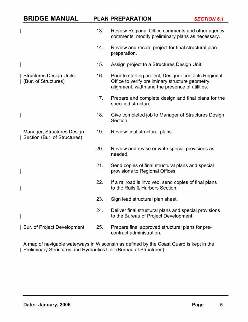
| 13. Review Regional Office comments and other agency comments, modify preliminary plans as necessary.
14. Review and record project for final structural plan
preparation.
| 15. Assign project to a Structures Design Unit.
| Structures Design Units 16. Prior to starting project, Designer contacts Regional | (Bur. of Structures) Office to verify preliminary structure geometry,
alignment, width and the presence of utilities.
17. Prepare and complete design and final plans for the specified structure.
| 18. Give completed job to Manager of Structures Design
Section. Manager, Structures Design 19. Review final structural plans.
| Section (Bur. of Structures)
20. Review and revise or write special provisions as needed.
21. Send copies of final structural plans and special
| provisions to Regional Offices.
22. If a railroad is involved, send copies of final plans | to the Rails & Harbors Section.
23. Sign lead structural plan sheet.
24. Deliver final structural plans and special provisions
| to the Bureau of Project Development.
| Bur. of Project Development 25. Prepare final approved structural plans for pre- contract administration. A map of navigable waterways in Wisconsin as defined by the Coast Guard is kept in the
| Preliminary Structures and Hydraulics Unit (Bureau of Structures).
BRIDGE MANUAL PLAN PREPARATION SECTION 6.2
Date: January, 2006 Page 6
6.2 PRELIMINARY PLANS
(1) Structure Survey Report
| The Structure Survey Report is prepared by Regional Office personnel to request a structure improvement project. The following forms in word format are used and are available at: http://www.dot.wisconsin.gov/forms/index.htm
Under the “Plans and Projects” heading:
DT1694 - English-Separation Structure Survey Report DT1696 - English Rehabilitation Structure Survey Report DT1698 - English-Stream Crossing Structure Survey Report
(use for Culverts also)
The front of the form lists the supplemental information to be included with the report. Duplicate reports and supplemental information are required for Federal aid primary and Interstate projects.
When preparing the Structure Survey Report, designers will make their best estimate of structure type and location of substructure units. The completed Structure Survey Report with the locations of the substructure units and all
required attachments and supporting information will then be submitted to the Geotechnical Section, attention Chief Geotechnical Engineer, through the | Regional Soils Engineer, and to the Preliminary Structures & Hydraulics Unit, | attention Preliminary Structures & Hydraulics Supervisor. This submittal will
take place a minimum of 15 months in advance of the final plans due date | shown on the Structure Survey Report. Under this plan, the box on the
Structure Survey Report titled, "Have soil borings been requested" should | always be checked "yes". The Geotechnical Section has responsibility for | conducting the necessary soil borings. The Preliminary Structures and | Hydraulics Unit and the Geotechnical Section will coordinate activities to
deliver the completed preliminary plans on schedule.
In most instances, the geotechnical work will proceed after the receipt of the Structure Survey Report, but in advance of the development of the preliminary bridge plans. However, special circumstances may require that the preliminary bridge plans precede the geotechnical work. The Geotechnical Section may request preliminary bridge plans under the following conditions.
1. A review of available subsurface information indicates the
probability of very shallow and highly variable bedrock. 2. The span on the Structure Survey Report falls in the 30 to 40 (9
to 12 meter) range and the decision between a bridge or a box culvert is not evident.

BRIDGE MANUAL PLAN PREPARATION SECTION 6.2
Date: January, 2006 Page 7
3. The Structure Survey Report indicates a multiple span structure in excess of 100 feet (30 meters) over a body of water.
| The Project Manager may also request information on structure type and
substructure locations if such information is necessary to expedite the environmental process.
Under this process, the scheduling of geotechnical work is coordinated with
| the Preliminary Structures & Hydraulics Unit toward completion of the bridge plans by the final plan due date. If other geotechnical work is required for the project, the designer should coordinate with the Regional Soils Engineer and the Geotechnical Section to promote efficiency of field drilling operations.
If the preliminary bridge plans are required more than one year in advance of the final plan due date on the Structure Survey Report due to the unique needs of the project, the project manager should discuss this situation with the Preliminary Structures & Hydraulics Supervisor prior to submitting the Structure Survey Report. A note discussing the agreed upon schedule should then be attached to all copies of the Structure Survey Report so all parties are aware of the schedule. The Geotechnical Section is responsible for scheduling the borings.
| Coordination early in the design process with DNR regarding removal | techniques for the existing structure, and new structure placement and type is
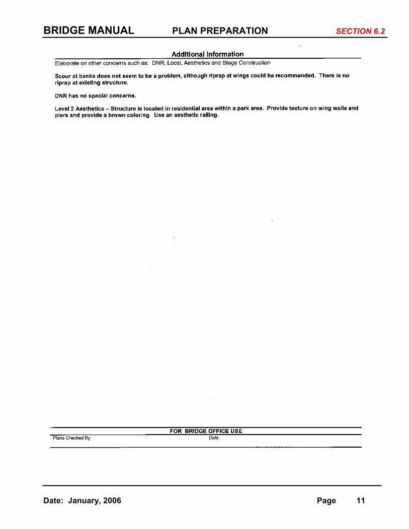
very important. The status of any agreements with the DNR, that affect the structure should be noted under additional information on the Structure Survey Report.
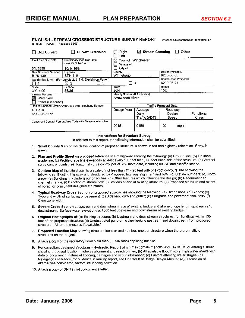
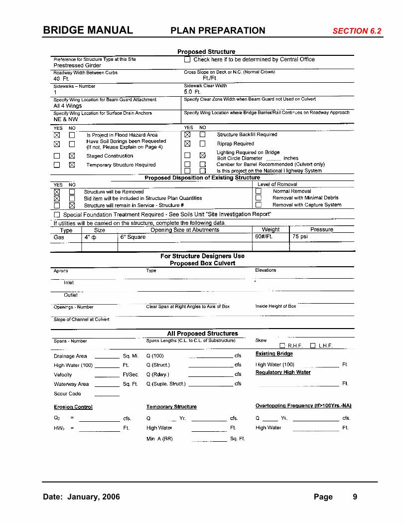
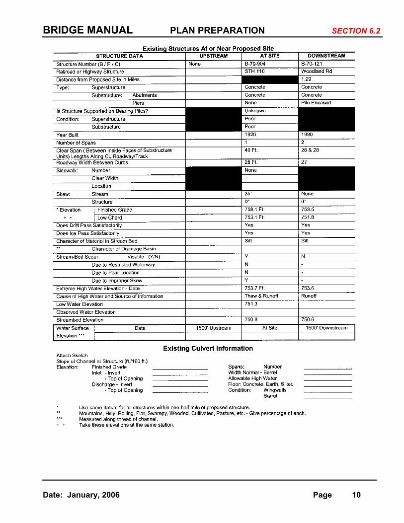
Following is a sample of a Stream Crossing Structure Survey report.
(2) Preliminary Layout
A. General. The preparation of a preliminary layout for structures is
primarily for the purpose of presenting an exhibit to the agencies involved for approval, before proceeding with final design and preparation of detail plans. When all the required approvals are obtained, the preliminary layout is used as a guide for final design and plan preparation.
For box culverts a preliminary drawing is usually not prepared. Information required to be submitted as a part of the survey report for a box culvert is usually sufficient to serve as a preliminary layout. The drawings for preliminary layouts are on sheets having an overall width of 11 inches and an overall length of 17 inches.
BRIDGE MANUAL PLAN PREPARATION SECTION 6.2
Date: January, 2006 Page 8
BRIDGE MANUAL PLAN PREPARATION SECTION 6.2
Date: January, 2006 Page 9
BRIDGE MANUAL PLAN PREPARATION SECTION 6.2
Date: January, 2006 Page 10
BRIDGE MANUAL PLAN PREPARATION SECTION 6.2
Date: January, 2006 Page 11
BRIDGE MANUAL PLAN PREPARATION SECTION 6.2
Date: January, 2006 Page 12
B. Basic Considerations. The following criteria are used for the preparation of preliminary plans.
1. Selection of Structure Type. Refer to Chapter 17, Superstructure-
General, for a discussion of structure types.
2. Span Arrangements. For stream crossings the desired minimum vertical clearance from high water to low steel is given in Chapter 8.0-Hydraulics. Span lengths for multiple span stream crossings are in most cases a matter of economics and the provision for an opening that adequately passes ice and debris. For structures over navigable streams, the vertical and horizontal clearance of the navigable span are determined by the U.S. Coast Guard after considering the interests of both highway and waterway transportation users.
For most of the ordinary grade separation structures the requirements for horizontal clearance determine the span arrangements. Refer to Chapter 17.0-Superstructure-General for span length criteria.
3. Economics. Economy is a primary consideration in determining the
type of structure to be used. Refer to Chapter 5.0-Economics and Costs, for cost data.
At some stream crossings where the grade line permits considerable head room, investigate the economy of a concrete box culvert versus a bridge type structure. When economy is not a factor, the box culvert is the preferred type from the standpoint of
| maintenance costs, highway safety, flexibility for roadway construction, and provision of a facility without roadway width restrictions.
4. Aesthetics. Recognition of aesthetics as an integral part of a
structure is essential if bridges are to be designed in harmony with adjacent land use and development. Refer to Chapter 4.0-Aesthetics.
5. Hydraulic Consideration. Stream crossing structures are influenced
by stream flow, drift, scour, channel conditions, ice, | navigation, and conservation requirements. This information is
submitted as part of the Structure Survey Report. Refer to Chapter 8 for Hydraulic considerations and Section 8.1(5) for Temporary Structure Criteria.
BRIDGE MANUAL PLAN PREPARATION SECTION 6.2
Date: January, 2006 Page 13
6. Geometrics of Design. The vertical and horizontal clearance roadway widths, design live loading, alignment, and other pertinent geometric requirements are given in Chapter 3.
7. Maintenance. All bridge types require structural maintenance
during their service life. Maintenance of approaches, embankments, drainage, substructure, concrete deck, and minor facilities is the same for the various types of bridges. A minimum draining grade of 0.5% across the bridge is desirable to eliminate small ponds on the deck except for open railings where the cross slope is adequate.
Epoxy coated bar steel is required in all new decks and slabs.
Steel girders require periodic painting unless a type of weathering steel is used. Even this steel may require painting near the joints. It is more difficult to repaint steel girders that span busy highways.
Reinforced concrete box girders and voided slabs have a poor
experience in Wisconsin. They should not be used on new structures.
Deck expansion joints have proved to be a source of maintenance problems. Bridges designed with a limited number of watertight expansion devices are recommended.
8. Construction. Occasionally a structure is proposed over an existing
highway on which traffic must be maintained. If the roadway underneath carries high volumes of traffic, any obstruction such as falsework would be hazardous as well as placing undesirable vertical clearance restrictions on the traveled way. This is also true for structures over a railroad.
For structures over most high-volume roadways construction time, future maintenance requirements, and provision for future expansion of the roadway width, have considerable influence on the selection of the final product.
9. Foundations. Poor foundation conditions may influence the structure geometry. It may be more economical to use longer
| spans and fewer substructure units or a longer structure to | avoid high approach fills.
10. Environmental Considerations. In addition to the criteria listed
above all highway structures must blend with the existing site conditions in a manner that is not detrimental to environmental
BRIDGE MANUAL PLAN PREPARATION SECTION 6.2
Date: January, 2006 Page 14
factors. Preservation of fish and wildlife, pollution of waters, and the effects on surrounding property are of primary concern in protecting the environment. The design of structures and the treatment of embankments must consider these factors.
11. Safety. Safety is a prime consideration for all aspects of the
structure design and layout. Bridge railings are approved through actual vehicle crash testing.
C. Requirements of Drawing
1. Plan View. The plan view is preferably placed in the upper left-
| hand portion of the sheet at the largest scale practical (1”=10’) and shows the following basic information:
a. Structure span lengths, (center-to-center of piers and to
centerline of bearing at abutments, end distance from centerline of bearing to back face of abutment and overall length of structure).
b. Dimensions along the reference line except for structures
on a curve in which case they are along a tangent to the curve.
c. Stations are required at centerline of piers, centerline of
bearing at abutments, and end of deck or slab.
d. Stations at intersection with reference line of roadway underneath for grade separation structures.
e. Direction of stationing increase for highway or railroad
beneath a structure.
f. Detail the extent of slope paving or riprap. g. Direction of stream flow and name if a stream crossing. h. Highway number and direction and number of traffic lanes. i. Horizontal clearance dimensions, pavement, shoulder,
sidewalk, and structure roadway widths.
j. Median width if dual highway.
k. Skew angles and angles of intersection with other highways, streets or railroads.
BRIDGE MANUAL PLAN PREPARATION SECTION 6.2
Date: January, 2006 Page 15
l. Horizontal curve data if within the limits of the structure showing station of PC, PT, and PI.
| m. Location of and vertical clearance at point of critical vertical | clearance if highway or railroad separation. (For both | roadway directions on divided highways).
n. If floor drains are proposed the type, approximate spacing,
| and whether downspouts are to be used.
| o. Existing structure description and number, buildings, underground utilities and pole lines giving owner's name and whether to remain in place, be relocated or abandoned. Show a tie dimension between old and new work.
| p. Indicate which wingwalls have beam guard rail attached if
any and wing lengths.
q. Structure numbers on plan. North Arrow.
r. Excavation protection for railroads.
s. Location of deck lighting or utilities if any.
t. Name Plate location.
| u. Locations of surface drains on approach pavement.
2. Elevation View. The elevation view is preferably placed below the plan view. If the structure is not skewed the substructure units are to be a straight projection from the plan view. If skewed, the elevation is a view normal to substructure units. The view shows the following basic information:
a. Profile of existing groundline or streambed.
b. Cross-section of highway or channel below showing back
slopes at abutments. c. Elevation of top of berm and rate of back slope used in
figuring length of structure.
d. Type and extent of slope paving or riprap on back slopes.
e. Proposed elevations of bottom of footings and type of piling if required.

BRIDGE MANUAL PLAN PREPARATION SECTION 6.2
Date: January, 2006 Page 16
f. Depth of footings for piers of stream crossing and if a seal is required, show and indicate by a note.
g. Location and amount of minimum vertical clearance.
| h. Streambed, observed and high water elevations for stream crossings.
i. Location of underground utilities, with size, kind of material
and elevation indicated.
j. Location of fixed and expansion bearings.
k. Location and type of expansion devices.
| l. Use a scale of 1” = 10’ whenever possible.
2. Cross-Section View. The cross-section view need only be a half section if symmetrical about a reference line, otherwise it is a full
| section taken normal to reference line. Use a scale of (1” = 4’) whenever possible. A view of a typical pier is shown as a part of the cross-section. The view shows the following general information:
a. Slab thickness, curb height and width, type of railing.
b. Horizontal dimensions tied into a reference line or centerline
of roadway.
| c. Steel beam or girder spacing with beam/girder depth.
d. For prestressed girders approximate position of exterior girders.
e. Direction and amount of crown or superelevation. f. Point referred to on profile grade.
| g. Type of pier with size and number of columns proposed.
h. For solid, hammerhead or other type pier approximate size
to scale.
i. If length of concrete pier cap between outer pier columns exceeds approximately 60 feet (20 meters), provide an opening in the cross girder for temperature changes and
BRIDGE MANUAL PLAN PREPARATION SECTION 6.2
Date: January, 2006 Page 17
concrete shrinkage, or design the pier cap for temperature and shrinkage to eliminate the opening.
j. Dimension minimum depth of bottom of footings below ditch
or finished ground line or if railroad crossing below top of rail. k. Location for public and private utilities to be carried in the
| superstructure. Label owner's name of utilities.
l. Location of lighting on the deck or under the deck if any.
4. Other Requirements
a. Profile grade line across structure showing tangent grades and length of vertical curve. Station and elevation of PC, PI, PT, and centerline of all substructure units.
Profile grade line of highway beneath structure if highway separation or of top rail if railroad separation. Stations along top of rail are to be tied into actual stationing as established by railroad company.
b. Complete curve data of all horizontal curves which may
influence layout of structure.
c. Channel change section if applicable. Approximate stream bed elevation at low point.
d. Any other view or detail which may influence the bridge type,
length or clearance. e. List design data including Ultimate Stresses for materials: (1) Concrete Superstructure (4) Structural Steel (2) Concrete Substructure (5) Prestressed Concrete (3) Bar Steel Reinforcement (6) Prestressing Steel
Foundations
(1) Soil Bearing Pressure (2) Pile Type and Capacity
Ratings
(1) Design (3) Operating (2) Inventory (4) Max. Vehicle Weight (250 kips max.)
Hydraulic Data
BRIDGE MANUAL PLAN PREPARATION SECTION 6.2
Date: January, 2006 Page 18
Base Flood
(1) 100 Year Discharge (5) Waterway Area (2) Stream Velocity (6) Drainage Area (3) Highwater Elevation (7) Scour Critical Code
(4) Q2 Elevation (Based on new structure opening)
Overtopping Flood OR (Overtopping N.A. for Floods
(1) Overtopping Frequency Greater Than the 100 Year (2) Overtopping Elevation Flood) .
(3) Overtopping Discharge
f. Show traffic data. Give traffic count, data and highway for each highway on grade separation or interchange structure.
D. Utilities
In urban areas, public and private utilities generally have their facilities such as sewers, water cables, pipes, ducts, etc., underground, or at river crossings, in the streambed.
If these facilities cannot be relocated, they may interfere with the most economical span arrangement. The preferred location of light poles is at
the abutments or piers.
Overhead power lines may cause construction problems or maintenance | inspection problems. Verify if they exist and notify Utilities & Access | Management Unit (Bureau of Tech. Services) to have them removed.
| It is the general policy to not place utilities on the structure. The Utilities & | Access Management Unit approves all utility applications and determines
whether utilities are placed on the structures or can be accommodated some other way. Refer all requests to them. Also see Chapter 18 of the
| FDM and Chapter 4 of “WisDOT Guide to Utility Coordination”.
(3) Distribution of Exhibits
A. Federal Highway Administration (FHWA). Preliminary plan exhibits listed below are submitted to the FHWA for their review and comment in accordance with Federal Aid Highway Program Manual, Vol. 6, Chapter 1, Section 2, Subsection 1. In addition to the structures described in the Manual (moveable bridges, unusual bridges, new structure types, major bridges costing more than $10,000,000, major channel changes), FHWA also requests that preliminary structure plans be submitted for all railroad

BRIDGE MANUAL PLAN PREPARATION SECTION 6.2
Date: January, 2006 Page 19
grade separation structures. Material to be submitted consists of one print or copy of the following:
1. Preliminary drawing.
2. Log of borings. 3. Evaluation report of borings. 4. Survey report for stream crossing structures. 5. Contour map.
6. Typical section of roadway approaches. 7. Plan and profile of approach roadways.
8. Hydraulic report (See Chapter 8.0) 9. County map showing location of new and existing structures.
10. Any other information or drawings which may influence location, layout or design of structure.
B. Coast Guard. Current permit application guides published by the 2nd or
9th Coast Guard District should be followed. For Federal Aid projects, applicants must furnish two copies of the Final Environmental Impact
| Statement accepted by the lead agency. The Regional Office will also forward Water Quality Certification obtained from the Department of Natural Resources.
| C. Regions. One print of all preliminary drawings is sent to the Regional
Office involved, for their review. For structures financed partially or wholly by a county, city, village or township, their approval should be obtained by
| the Regional Office and approval notice forwarded to the Bureau of | Structures.
D. Utilities. For all structures which involve a railroad, four prints of the
| preliminary drawing are submitted to the Utilities & Access Management | Unit for submission to the railroad company for approval.
If private or public utilities wish to make application to attach their facilities
| (water, and sewer mains, ducts, cables, etc.) to the structure, they | must apply to the Utilities & Access Management Unit for approval.
E. Other Agencies. One set of preliminary plans (preliminary layout, plan &
profile, and contour map) for stream crossing bridges are forwarded to the Department of Natural Resources for comment, in accordance with the cooperative agreement between the Department of Transportation and the Department of Natural Resources. (See Chapter 8.0).
BRIDGE MANUAL PLAN PREPARATION ___________________________________________________________________________
SECTION 6.3
Date: January, 2006 Page 20
6.3 FINAL PLANS
This section describes the general requirements for the preparation of construction plans for bridges, culverts, retaining walls and other related highway structures. It
| provides a standard procedure, form, and arrangement of the plans for uniformity.
(1) General Requirements
| A. Drawing Size. Sheets are 11 inches wide from top to bottom and 17 inches long. A border line is provided on the sheet 1 inch from the left edge, and ¼ inch from other edges. Title blocks are provided on the first sheet for a signature and other required information. The follow sheets contain the same information without provision for a signature.
B. Scale. All drawings insofar as possible are drawn to scale. Such details as reinforcing steel, steel plate thicknesses, etc. are not scaled. The scale is adequate to show all necessary details.
| C. Line Thickness. Object lines are the widest line on the drawing. Lines
showing all or part of an existing structure or facility are shown by dotted lines of somewhat lighter weight.
| Lines showing bar steel are lighter than object lines and are drawn
continuous without any break. Dimension and extension lines are lighter | than bar steel lines but heavy enough to make a good reproduction.
| D. Lettering and Dimensions. All lettering is upper case. Lettering and
dimensions are read from the bottom or right hand side and should be | placed above the dimension lines. Notes and dimension text are 0.12 | inches high; view titles are 0.20 inches high (based on full size sheet, 22” | x 34”). Dimensions are given in feet and inches (millimeters). Elevations
are given in decimal form to the nearest 0.01 of a foot (0.001 of a meter). Always show two (three) decimal places. Although plan dimensions are very accurate, the contractor should use reasonable tolerances during construction of the project by building to the accuracy required. Detail structural steel to the thickness of the material involved.
E. Notes. Show any notes to make the required details clear on the plans.
Do not include material that is part of the specifications. F. Standard Insert Drawings. Standard detail sheets are available for railings
and parapets, prestressed girders, bearings, expansion joints, and drains. Fill in the dimensions and titles required and insert in the final plans.
Standard insert sheets can be found at:
http://trust.dot.state.wi.us/extntgtwy/dtid_bos/extranet/structures/index.htm
BRIDGE MANUAL PLAN PREPARATION ___________________________________________________________________________
SECTION 6.3
Date: January, 2006 Page 21
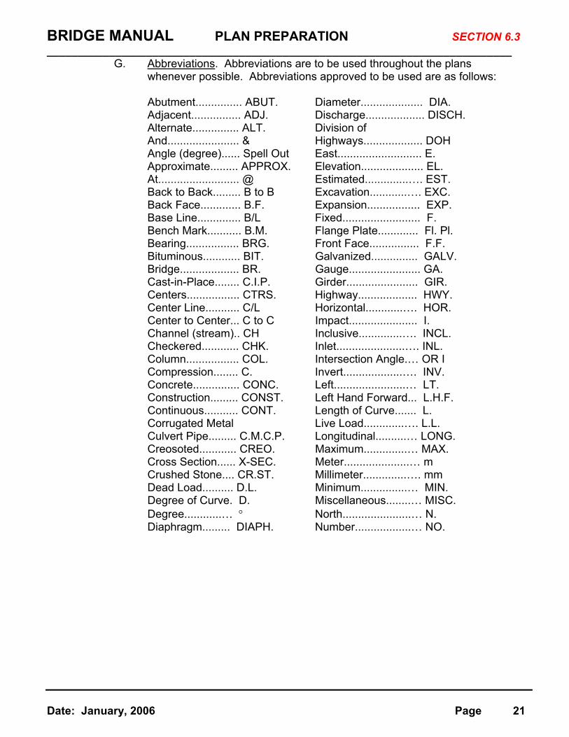
G. Abbreviations. Abbreviations are to be used throughout the plans whenever possible. Abbreviations approved to be used are as follows:
Abutment............... ABUT. Diameter.................... DIA. Adjacent................ ADJ. Discharge................... DISCH. Alternate............... ALT. Division of And....................... & Highways................... DOH Angle (degree)...... Spell Out East........................... E. Approximate......... APPROX. Elevation.................... EL. At.......................... @ Estimated..............…. EST. Back to Back......... B to B Excavation............…. EXC. Back Face............. B.F. Expansion................. EXP. Base Line.............. B/L Fixed......................... F. Bench Mark........... B.M. Flange Plate............. Fl. Pl. Bearing................. BRG. Front Face................ F.F. Bituminous............ BIT. Galvanized............... GALV. Bridge................... BR. Gauge....................... GA. Cast-in-Place........ C.I.P. Girder....................... GIR. Centers................. CTRS. Highway................... HWY. Center Line........... C/L Horizontal............…. HOR. Center to Center... C to C Impact...................... I. Channel (stream).. CH Inclusive..............…. INCL. Checkered............ CHK. Inlet......................…. INL. Column................. COL. Intersection Angle.… OR I Compression........ C. Invert...................…. INV. Concrete............... CONC. Left.......................… LT. Construction......... CONST. Left Hand Forward... L.H.F. Continuous........... CONT. Length of Curve....... L. Corrugated Metal Live Load.............…. L.L.
Culvert Pipe......... C.M.C.P. Longitudinal..........… LONG. Creosoted............ CREO. Maximum..............… MAX. Cross Section...... X-SEC. Meter.....................… m Crushed Stone.... CR.ST. Millimeter..............…. mm Dead Load.......... D.L. Minimum...............… MIN. Degree of Curve. D. Miscellaneous........… MISC. Degree............… ° North......................… N. Diaphragm......... DIAPH. Number..................… NO.
BRIDGE MANUAL PLAN PREPARATION ___________________________________________________________________________
SECTION 6.3
Date: January, 2006 Page 22
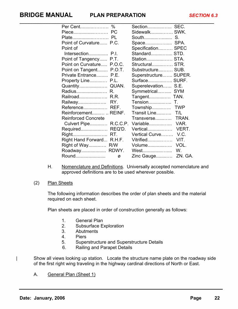
Per Cent..........………. % Section............…... SEC. Piece................……… PC Sidewalk.........……. SWK. Plate................………. PL South..........…........ S. Point of Curvature...... P.C. Space............…..... SPA. Point of Specification....…… SPEC
Intersection............... P.I. Standard.........….... STD. Point of Tangency...... P.T. Station.............…… STA. Point on Curvature..... P.O.C. Structural.........…… STR. Point on Tangent........ P.O.T. Substructure....…… SUB. Private Entrance......... P.E. Superstructure..….. SUPER. Property Line..........… P.L. Surface.............….. SURF. Quantity.................…. QUAN. Superelevation.….. S.E. Radius...................…. R. Symmetrical...….... SYM Railroad................….. R.R. Tangent............…. TAN. Railway................….. RY. Tension............….. T. Reference...............… REF. Township.........….. TWP Reinforcement......… .. REINF. Transit Line......….. T/L Reinforced Concrete Transverse.......….. TRAN.
Culvert Pipe..........… R.C.C.P. Variable...........…... VAR. Required................…. REQ'D. Vertical............…… VERT. Right.....................….. RT. Vertical Curve.……. V.C. Right Hand Forward... R.H.F. Vitrified...........……. VIT. Right of Way.........…. R/W Volume.............….. VOL. Roadway................... RDWY. West...............….... W. Round....................... ø Zinc Gauge........…. ZN. GA.
H. Nomenclature and Definitions. Universally accepted nomenclature and
approved definitions are to be used wherever possible.
(2) Plan Sheets
The following information describes the order of plan sheets and the material required on each sheet.
Plan sheets are placed in order of construction generally as follows:
1. General Plan 2. Subsurface Exploration 3. Abutments 4. Piers 5. Superstructure and Superstructure Details 6. Railing and Parapet Details
| Show all views looking up station. Locate the structure name plate on the roadway side of the first right wing traveling in the highway cardinal directions of North or East. A. General Plan (Sheet 1)

BRIDGE MANUAL PLAN PREPARATION ___________________________________________________________________________
SECTION 6.3
Date: January, 2006 Page 23
1. Plan View
Same requirements as specified for preliminary drawing, except do not show contours of groundline and as noted below.
a. Sufficient dimensions to layout structure in the field. b. Describe the structure with a simple note such as: Four span
continuous steel girder structure. c. Give the location of the name plate.
d. Station at face of paving notch on each end of bridge.
2. On Structure Replacements
Show existing structure in dashed-lines on Plan View. Also, provide the existing structure type in the General Notes.
3. Elevation View
Same requirements as specified for preliminary plan except:
a. Show elevation at bottom of all substructure units. b. Give estimated pile lengths where used.
4. Cross-Section View
Same requirements as specified for preliminary plan except:
a. For railroad bridges show a railroad cross-section. b. View of pier may or may not be shown.
5. Grade Line
Same requirements as specified for preliminary plan.
6. Design and Traffic Data Same requirements as specified for preliminary plan plus show Design | Specifications as: AASHTO STD. 2003.
7. Estimated Quantities
a. Enter bid item numbers, bid items and quantities as they appear,
and in the order in which they appear in the "Schedule of Bid Items" of the Standard Specifications. Put items not provided for at the bottom of the list. Enter quantities for each part of the structure, (superstructure, each abutment, each pier) under a separate column with a grand total.

BRIDGE MANUAL PLAN PREPARATION ___________________________________________________________________________
SECTION 6.3
Date: January, 2006 Page 24
Quantities are to be bid under items for the Structure Type and not by the "B" or "C" numbers. For example, concrete for a multi-cell box culvert exceeding a total length of 20 feet (6.1 m) is to be bid under item Concrete Masonry Culverts. As another example, a bridge having a length less than 20 feet would be given a "C" number; however, the concrete bid item is Concrete Masonry Bridges.
b. For incidental items to be furnished for which there is no bid item,
and compensation is not covered by the Standard Specifications or Special Provisions, note on the plans the most closely related bid item that is to include the cost in the price bid per unit of item. As an example, the cost of concrete inserts is to be included in the price bid per cubic yard (meter) of concrete masonry.
8. General Notes
A standard list of notes is given in Sections 6.3(2)A(a) and 6.3(2)A(b). Use
the notes in this table that apply to the structure drawn on the plans. 9. List of Drawings
Each sheet is numbered sequentially beginning with 1 for the first sheet. Give the sheet number and title of sheet.
10. Bench Marks
Give the location, description and elevation of the nearest bench mark.
11. Title Block
Fill in all data for the Title Block except the signature. The title of this sheet is "General Plan". Use the line below the structure number to describe the type of crossing. (Example: STH 15 SB over Fox River). For Design Spec. use AASHTO and year. If LRFD specs. are used, use AASHTO LRFD and year.
12. Professional Seal
All final bridge plans prepared by Consultants or Governmental Agencies
shall be professionally sealed, signed, and dated on the general plan sheet. | This is not required for WisDOT prepared plans, as they are covered | elsewhere.
(a) Plan notes for New Bridge Construction

BRIDGE MANUAL PLAN PREPARATION ___________________________________________________________________________
SECTION 6.3
Date: January, 2006 Page 25
1. Drawings shall not be scaled. Bar Steel Reinforcement shall be embedded 2” (50 mm) clear unless otherwise shown or noted.
2. All field connections shall be made with 3/4” (M20) diameter
friction type high-tensile strength bolts unless shown or noted otherwise.
3. All dimensions are in inches unless otherwise noted.
4. Slab falsework shall be supported on piles or the substructure unless an alternate method is approved by the Engineer.
5. All stations and all elevations are in feet (meters). 6. All reinforcing bars are English (metric) and the first two digits of the bar mark signify the bar size.
7. The slope of the fill in front of the abutments shall be covered with heavy riprap and geotextile fabric to the extent shown on this sheet and in the abutment details.
8. The slope of the fill in front of the abutments shall be covered
with slope paving to the extent shown on this sheet and in the abutment details.
9. The stream bed in front of the abutment shall be covered with
riprap as shown on this sheet and in the abutment details.
10. The existing stream bed shall be the upper limits of excavation at the piers.
11. The existing groundline shall be the upper limits of
excavation for structures. 12. The finished graded section shall be the upper limits of
excavation for structures. 13. The upper limits of excavation for structures for the
abutments shall be the bottom of slope protection.
14. Pile splices at piers, involving bending, shall be made by a certified welder.
15. Within the length of the box all spaces excavated and not
occupied by the new structure shall be backfilled with

BRIDGE MANUAL PLAN PREPARATION ___________________________________________________________________________
SECTION 6.3
Date: January, 2006 Page 26
Structure Backfill to the elevation and section existing prior to excavation within the length of the culvert.
16. At abutments all spaces excavated and not occupied by the
new structure shall be backfilled with granular backfill.
17. Concrete inserts to be furnished by the utility company and placed by the contractor. Cost of placing inserts shall be included in the bid price for concrete masonry.
18. Prestressed Girder Bridges - The minimum concrete haunch
shall be 2" (50 mm) for design calculations and the haunch concrete quantity is based on an average haunch depth of 2 1/2" (60 mm) which is the maximum haunch quantity for which
the Contractor will be paid.
(b) Plan Notes for Bridge Rehabilitation 1. Dimensions shown are based on the original structure plans. 2. All concrete removal not covered with a concrete overlay shall be defined by a 1 inch (25 mm) deep saw cut.
3. Utilize existing bar steel reinforcement where shown and extend 24 bar diameters into new work.
4. Concrete expansion bolts and inserts to be furnished and
placed by the contractor under the bid price for concrete masonry.
5. At "Curb Repair" expose existing reinforcement a minimum of 1 1/2” (40 mm) clear.
6. Existing floor drains to remain in place. Remove top of deck in drain area as directed by the Field Engineer to allow placing and sloping of 1 1/2” (40 mm) concrete overlay.
7. Expansion joint assembly, including anchor studs and hardware
shall be paid for in the lump sum price bid as | "Expansion Device B-_____” or “Expansion Device Modular | B- ______”.
8. Clean and fill existing longitudinal and transverse cracks with
penetrating epoxy as directed by the Field Engineer. 9. Variations to the new grade line over 1/4” (5 mm) must be
submitted by the Field Engineer to the Structures Design Section for review.
BRIDGE MANUAL PLAN PREPARATION ___________________________________________________________________________
SECTION 6.3
Date: January, 2006 Page 27
10. If new name plate is required, original construction year is _____.
B. Subsurface Exploration
This sheet is initiated by the Geotechnical Engineer. The following information is required on the sheet. Bridge details are not drawn by the Geotechnical Engineer. 1. Plan View
Show a plan layout of structure with survey lines, reference lines, pier and abutment locations and location of borings and probings plotted to scale.
On box culvert structure plans, show three profile lines of the existing ground elevations (along the centerline and outer walls of the box). Scale the information for these lines from the site contour map that is a part of the structure survey report.
2. Elevation
a. Show a centerline profile of existing ground elevation.
b. Give a simple bridge elevation view showing footing elevations, test
pile lengths drawn to scale, general outline of structure, and finished profile lines. Also show the service pile lengths.
c. Show the kind of material, its located depth, and the blow count of
the split spoon sampler for each boring. Give the blow count at about 5 foot (2 meter) intervals or where there is a significant change in material.
C. Abutments
Use as many sheets as necessary to show details clearly. Show all bar steel required using standard notations; solid lines lengthwise and solid dots in cross section. “Give dimensions for a skewed abutment to a reference line which passes through the intersection for the longitudinal structural reference line and centerline of bearing of the abutment. Give the dimension, from centerline of bearing to backface of abutment along the longitudinal reference line and the
| offset distance if on a skew. This is for Regions who prefer the working point at backface of the abutment. Show the skew angle. *If there is piling, show a complete footing layout giving piling dimensions tied to the reference line. Number all the piles. Give the type of piling, length and minimum bearing value. Show a welded field splice for cast in place concrete or steel H piles.
* For Type A1 and A3 abutments.

BRIDGE MANUAL PLAN PREPARATION ___________________________________________________________________________
SECTION 6.3
Date: January, 2006 Page 28
Bridge seats for steel bearings are level within the limits of the bearing plate. Slope the bearing area of prestressed girders without steel bearings if the edges of the bearing area differ in elevation by 1/4” (5 mm) or more. Slope the bridge seat between bearings 1” (25 mm) from front face of parapet to front face of abutment. Give all bearing elevations.
1. Plan View
a. Place a keyed construction joint near the center of the abutment if the length of the body wall exceeds 50 feet (15 m). Make the keyway as large as feasible and extend the horizontal bar steel through the joint.
b. Dimension wings in a direction parallel and perpendicular to the wing
centerline.
c. Dimension angle between wing and body if that angle is different from the skew angle of the abutment.
2. Elevation
a. Use steel shims under steel bearings if the difference in elevations
between adjacent girders is less than 1/2” (10 mm). If greater, step the bearing areas.
b. Give beam seat, wing (front face and wing tip), and footing
elevations to the nearest .01 of a foot (.001 of a meter). c. Give vertical dimension of wing.
3. Wing Elevation 4. Body Section
Place an optional keyed construction joint in the parapet at the bridge seat elevation if there is a parapet.
5. Wing Sections
6. Bar Steel Listing and Detail 7. List of Quantities
a. Concrete Masonry - Includes parapet b. Reinforcing Steel c. Piling - Delivered and Driven d. 2 Ply Membrane Waterproofing e. Filler - Size only required
BRIDGE MANUAL PLAN PREPARATION ___________________________________________________________________________
SECTION 6.3
Date: January, 2006 Page 29
f. Pipe Underdrain
Use the following views where necessary:
8. Pile Plan & Splice Detail 9. View Showing Limits of Excavation and Backfill
10. Special Details for Utilities
11. Drainage Details
D. Piers
Use as many sheets as necessary to show all details clearly. One sheet may show several piers if only the height, elevations and other minor details are different.
Give dimensions for a skewed pier to a reference line which passes through the intersection of the longitudinal structural reference line and the pier centerline. Show the skew angle. Dimension the centerline spacing of superstructure girders. 1. Plan View
Show dimensions, footings, cap steps, beam spacings, skew angle, and shims if used.
2. Elevation
Show dimensions and elevations. Show lengths of all columns for clarity. Give the elevation of the bottom of footings and beam seats. Refer to abutments for detailing bridge seats. Dimension all bar steel and stirrups.
3. Footing Plan
Show dimensions for pile spacing, pile numbers and reinforcing steel in footing.
4. List of Quantities (Give for each pier separately)
a. Concrete Masonry b. Reinforcing Steel c. Piling - Delivered and Driven d. Test Piling - Timber only e. Cofferdam - Required if a seal is shown on plans.
5. Bar Steel Listing and Details
BRIDGE MANUAL PLAN PREPARATION ___________________________________________________________________________
SECTION 6.3
Date: January, 2006 Page 30
6. Pile Splice Detail (If different from abutment only).
7. Cross Section thru Column and Pier Cap
Detail anchor bolts between reinforcing bars so minimum clearance is as shown on Standard 13.1. Long steel bridges may require more clearance. This allows an erection tolerance for the structural steel so that the bar steel is not pierced by the anchor bolts if the bearing is shifted.
E. Superstructure
Use as many sheets as are necessary to show all details clearly. Standard insert sheets are available to show many standard details. The title, project number, and a few basic dimensions are added to these standard sheets.
1. All Structures
a. Show the cross-section of roadway, plan view and related details,
elevation of typical girder or girders, details of girders, and other details not shown on standard insert sheets. Complex bearings and expansion joint details are not shown on standard insert sheets. All drawings are to be fully dimensioned and show such sections and views as needed to detail the superstructure completely.
b. Show the total dead load deflections at 0.1 points of each span.
| Give deflections to nearest 1/8” (5 mm). c. Show a table of elevations of the top of slab at 0.1 points of the
spans. Show the top of slab elevations at the outside edge of slab. For steel girders show in the table the top of girder steel elevation after erection at each field splice and centerline of all bearings.
d. Show a pouring diagram for all slabs which have a concrete volume
that exceeds 250 cubic yards(230 cubic meters). See standard for location of construction joints.
e. Provide a paving notch at each end of all structures for rigid
approach pavements. See standard for details.
f. If the structure contains conduit for a deck lighting system, place the conduit in the concrete parapet. Place expansion devices on conduit which passes through structure expansion joints. For conduit that passes through deflection joints paint the conduit with a
heavy coat of bituminous paint 20” (500 mm) on each side of joint. Detail openings in bulkheads and give some flexibility to contractor.
BRIDGE MANUAL PLAN PREPARATION ___________________________________________________________________________
SECTION 6.3
Date: January, 2006 Page 31
g. Show the bar steel reinforcement in the slab, curb, and sidewalk with the transverse spacing and all bars labeled. Show the direction and amount of roadway crown.
h. On bridges with a median curb and left turn lane, water may be
trapped at the curb due to the grade slope and crown slope. If this is the case, make the cross slope flat to minimize the problem. Existing pavers cannot adjust to a variable crown line.
i. On structures with modular joints consider cover plates for the back of parapets when aesthetics are a consideration.
2. Steel Structures
a. Show the diaphragm connections on steel girders. Show the
spacing of rail posts on the plan view. b. Show a steel framing plan for all steel girders. Show the spacing of diaphragms.
c. On the elevation view of steel girders show dimension, material
required, field and shop splice locations, stiffener spacings, shear connector spacing, and any other information necessary to
construct the girder. In additional views show the field splice details and any other detail that is necessary.
d. Show the size and location of all weld types with the proper symbols
except for butt welds. Requirements for butt welds are covered by A.W.S. Specifications.
e. Show a blocking diagram with the required camber for all
continuous steel girder bridges. Blocking dimensions are required at all bearings, field splice points, and shop splice points where there is a change in direction or slope of the girder. Give all dimensions from a horizontal line passing through the low end of the girder at centerline of bearing.
f. Slabs of uniform thickness are used on steel girders. Variations in
thickness are achieved by haunching the slab over each girder. Haunches are formed off the top of the top flange. See the
standard for details. In general the minimum haunch depth along the girder is to be 1 1/4” (30 mm) although 2” is recommended to allow for construction tolerances. This is generally achieved by setting haunch depths of 2” (50 mm) at field splices and end
bearings. Haunch depth is the distance from the bottom of the concrete slab to the top of the top flange. Use of girder haunches eliminates some girder cambering.

BRIDGE MANUAL PLAN PREPARATION ___________________________________________________________________________
SECTION 6.3
Date: January, 2006 Page 32
g. Existing flange and web sizes should be shown to facilitate the sizing of bolts on Rehabilitation Plans.
F. Railing and Parapet Details
| Standard drawings are maintained by the Structures Development Section
showing railing and parapet details. Add the details and dimensions to these drawings that are unique to the structure being detailed. Compute the length along the slope of grade line rather than the horizontal dimension.
(3) Miscellaneous Information
A. Bill of Bars
Show a complete bill of bar steel reinforcement for each unit of the structure. Place this bill on the sheet to which the bars pertain. If the abutments or piers are similar, only one bar list is needed for each type of unit. Give each bar or group of bars a different mark if they vary in size, length, or location in a unit. Each bar list is to show the mark, number of bars, length, location and detail for each bar. Give bar lengths to the nearest 1” (50 mm) and segment lengths of bent bars to the nearest 1/2” (10 mm). Show all bar bends and hooks in detail. Identify all bars with a letter indicating the unit in which the bar is placed - A for abutment, P for pier, S for superstructure. Where units are multiple, each unit should have a different letter. Next use a one or two digit number to sequentially number the bars in a unit. P1008 indicates bar number 08 is a size number 10 bar located in a Pier.
Use a Bar Series Table where a number of bars the same size and spacing vary in length is a uniform progression. Use only one mark for all these bars and put the average length in the table.
Refer to the Standard drawings in Chapter 9.0 for more information on reinforcing bars such as minimum bend diameter, splice lengths, bar supports, etc.
When a bridge is constructed in stages, show the bar quantities for each stage. This helps the contractor with storage and retrieval during construction.
B. Box Culverts
BRIDGE MANUAL PLAN PREPARATION ___________________________________________________________________________
SECTION 6.3
Date: January, 2006 Page 33
Detail plans for box culverts are to be fully dimensioned and have sectional drawings needed to detail the structure completely. The following items are to be shown when necessary:
1. Plan View
2. Longitudinal section 3. Section thru box 4. Wing elevations 5. Section thru wings 6. Section thru cutoff wall 7. Vertical construction joint
8. Bar steel clearance details 9. Header details
10. North point, Bench mark, Quantities 11. Bill of bars, Bar details
12. General notes, List of drawings, Rip rap layout 13. Inlet nose detail on multiple cell boxes 14. Corner details
Bid items are excavation, concrete masonry, bar steel and rip rap. Non bid items are membrane waterproofing, filler and expansion bolts. In lieu of showing a contour map, show profile grade lines as described for Subsurface Exploration sheet.
See the standard details for box culverts for the requirements on vertical construction joints, apron and cutoff walls, longitudinal construction joints, and optional construction joints.
Name Plates are to be located by the Engineer in the field.
C. Miscellaneous Structures
Detail plans for other structures such as retaining walls, sign bridges, pedestrian bridges, and erosion control structures are to be detailed with the same requirements as previously mentioned.
D. Standard Drawings
| Standard drawings are maintained and furnished by the Structures | Development Section. These drawings show the common types of details
required on the contract plans.
E. Insert Sheets
| These sheets are maintained by the Structures Development Section and | are used in the contract plans to show standard details.
F. Change Orders and Maintenance Work
BRIDGE MANUAL PLAN PREPARATION ___________________________________________________________________________
SECTION 6.3
Date: January, 2006 Page 34
These plans are drawn on full size sheets.
G. Bench Marks
Bench mark caps are shown on all bridges and larger culverts. Locate the caps on a horizontal surface flush with the concrete. Show the location in close proximity to the Name Plate.
(4) Checking Plans
Upon completion of the design and drafting of plans for a structure, the final plans are usually checked by one person. Dividing plans checking between two or more Checkers for any one structure leads to errors many times. The plans are checked for compliance with the approved preliminary drawing, design, sufficiency and accuracy of details, dimensions, elevations, and quantities. Generally the information shown on the preliminary plan is to be used on the final plans. Revisions may be made to footing sizes and elevations, pile lengths, dimensions, girder spacing, column shapes, and other details not determined at
| the preliminary stage. Any major changes from the preliminary plan are to be | approved by the Chief Bridge Design Engineer.
Give special attention to unique details and unusual construction problems. Take nothing for granted on the plans.
The Checkers check the final plans against the Engineer's design and sketches to be sure all information is shown correctly. The Engineer prepares all sketches and notations not covered by standard drawings. A good Checker checks what is shown and noted on the plan and also checks to see if any essential details, dimensions, or notation have been omitted. Check the final plan Bid Items for
| conformity with those scheduled in the WisDOT Standard Specifications for | Highway and Structure Construction.
The Checker makes an independent Bill of Bars list to be sure the detailer has not omitted any bars when checking the quantity of bar steel.
Avoid making minor revisions in details or dimensions that have very little effect on cost, appearance, or adequacy of the completed structure. Check grade and bridge seat elevations and all dimensions to the required tolerances. The Checkers make all corrections, revisions, and notations on a print of the plan
and return it to the Plan Preparer. The Plan Preparer back checks all marks made by the checker before changing. Any disagreements are resolved with the supervisor.
Common complaints received from field people are dimension errors, small details crowded on a drawing, lettering is too small, and reinforcing bar length or quantity errors. After the plans are completed, the items in the survey folder are separated into
BRIDGE MANUAL PLAN PREPARATION ___________________________________________________________________________
SECTION 6.3
Date: January, 2006 Page 35
| the following groups by the Structures Design Unit Supervisor or plans checker: A. Items to be Destroyed When Construction is Completed
1. Miscellaneous correspondence and Transmittal letters. 2. Preliminary drawings and computations. 3. Prints of soil borings and plan profile sheets. 4. Quantity computations and bill of bars. * 5. Shop steel quantity computations. 6. Design checker's computations.
7. Designer Computations and computer runs of non-complex structures on non state maintained structures.
8. Layout sheets. 9. Elevation runs and bridge geometrics.
* 10. Falsework plans. 11. Miscellaneous Test Report
12. Photographs of Bridge Rehabs.
* These items are added to the packet during construction. B. Items to be Destroyed when Plans are Completed
1. All "void" material. 2. All copies except one of preliminary drawings. 3. Extra copies of plan and profile sheets. 4. Preliminary computer design runs.
Items in Group A should be placed together and labeled. Items in Group B
should be discarded. The following items are part of the Data Management System for Structures. The
location is shown for all items that need to be completed in order to properly manage the Structure data either by Structures Design personnel for in-house
projects or consultants for their designs. Data for filing that is generated outside the Bureau of Structures should be sent to the Structures Development Section.
| 1. Structure Inventory Form (Available on DOTNET) - New Bridge File – Data for this form is completed by the preliminary designer and plans
| checker. It is submitted to the Structures Development Section for entry into the File.
2. Load Rating Input File - Permits File - The designers submit an
electronic copy of the input data for load rating the structure to the | Structures Development Section. It is located for internal use at
//H32751/rating. * 3. Designer Computations and Inventory Superstructure Design Run
(Substructure
BRIDGE MANUAL PLAN PREPARATION ___________________________________________________________________________
SECTION 6.3
Date: January, 2006 Page 36
computer runs as determined by the Engineer) - **Bridgeview – The designers record design, inventory, operating ratings and maximum vehicle weights on the plans and place into the scanned folder.
| 4. Pile Driving Reports - Bridgeview - Structures Development Section
scans reports into Bridgeview.
5. Shop Drawings for Steel Bridges, Sign Bridges, Prestressed Girders, High Mast Poles, Retaining Walls, Floor Drains, Railings and all Steel Joints -
| Bridgeview - Metals Fabrication & Inspection Unit or other source sends to | the Structures Development Section to scan all data into Bridgeview.
6. Mill Tests, Heat Numbers and Shop Inspection Reports for all Steel Main
| Members - Bridgeview - Metals Fabrication & Inspection Unit sends electronic files data into Bridgeview.
7. Hydraulic and Scour Computations, Contour Maps and Site Report -
| Bridgeview - Data is placed into scanned folder by Preliminary Structures | & Hydraulics Unit.
* 8. Subsurface Exploration Report - Bridgeview - Report is placed into
| scanned folder by Preliminary Structures & Hydraulics Unit or electronic copies are loaded from Geotechnical files.
* 9. Structure Survey Report - Bridgeview - Report is placed into scanned
| folder by Preliminary Structures & Hydraulics Unit.
10. As Built Plans - Bridgeview - At bid letting, the printers place a digital | image of plans in a computer folder and send to the Structures | Development Section where the plan sheets are labeled and placed in | Bridgeview. As Built plans will replace bid letting plans when available | and will be scanned by the Structures Development Section.
| 11. Inspection Reports - New Bridge File - The Structures Maintenance
Section loads a copy of the following Inspection Reports into the New Bridge File.
A. Initial G. Underwater (UW-Probe/Visual B. Routine Visual H. Movable C. Fracture Critical I. Damage D. In-Depth J. Interim E. Underwater (UW)-Dive K. Posted F. Underwater (UW)-Surv
These items are placed into a Scanned Folder and loaded into Bridgeview
| by the Structures Development Section when construction is complete. ** Bridgeview – The electronic file where bridge data is stored for future use.

BRIDGE MANUAL PLAN PREPARATION SECTION 6.3 ___________________________________________________________________________
Date: January, 2006 Page 37
(5) Processing Plans A. Before P.S. & E. Process
1. File plans in plan drawers by county for consultant work, or 2. Maintain plans as PDF on E-plan server.
B. At P.S. & E. Processing 1. Prepare plans for bid letting process.
C. After Structure Construction
1. Any data in Design Folder is scanned and placed with bridge plans. 2. Original plan sheets and Design Folders are discarded.
BRIDGE MANUAL PLAN PREPARATION SECTION 6.4 _____________________________________________________________________________
Date: January, 2006 Page 38
6.4 COMPUTATION OF QUANTITIES
When the final drafting and checking is completed, the Engineering Specialist and checker are to prepare individual quantity calculations for the bid items listed on the plans. The following instructions apply to the computation on quantities.
Be neat and orderly with the work. Divide the work into units that are repetitive such as footings, columns, and girders. Label all items with a clear description. Use sketches for clarity. These computations may be examined by others in future years so make them understandable.
One of the most common errors made in quantity computation is computing only half of an item which is symmetrical about a centerline and forgetting to double the result.
Staged Construction - On projects where there is staged construction that will involve two construction seasons the following quantities should be split to match the staging to aid the contractor/fabricator: Concrete Masonry, Bar Steel Reinforcement, Structural Steel and
Bar Couplers. The other items are not significant enough to justify separating. Following is a list of commonly used bridge quantities. Be sure to use the appropriate item and avoid using incidental items as this is too confusing for the contractor and project manager.
| (1) Excavation for Structures Bridges (Structure)
This is a lump sum bid item. The limits of excavation are shown in the chapter in the manual which pertains to the structural item, abutments, piers, retaining walls, box culverts, etc.
The limits of excavation made into solid rock are the neat line of the footing.
(2) Backfill Granular or Backfill Structure Backfill Granular and Backfill Structure are bid in units of cubic yard. The pay
limits and quantity computations of backfill at abutments are shown in Chapter 12. (3) Concrete Masonry Bridges Show the total quantity to the nearest cubic yard. Show unit quantities to the nearest 0.1 cubic yard adjusted so the total of the unit quantities equals the total
quantity. In computing quantities no deduction is made for metal reinforcement, floor drains, conduits and chamfers less than 2”. Flanges of steel and prestressed
girders projecting into the slab are deducted. Deduct the volume of pile heads into footings and through seals for all piling except steel H sections. Deduct the actual volume displaced for precast concrete
BRIDGE MANUAL PLAN PREPARATION SECTION 6.4 _____________________________________________________________________________
Date: January, 2006 Page 39
and cast-in-place concrete piling. Deduct 0.02 cubic yard for each 14” of timber piles. Consider the concrete parapet railing on abutment wing walls as part of the concrete volume of the abutment.
(4) Prestressed Girder Type I (28-Inch; 36-Inch; 45-Inch; 54W-Inch; 72W-Inch) Record one type and length of prestressed girders to the nearest 3”. (5) Bar Steel Reinforcement HS Bridges or Bar Steel Reinforcement HS Coated
Bridges Record this quantity to the nearest 10 lbs. Designate if bar steel is coated and/or high strength. Include the bar steel in C.I.P. concrete piling in bar steel quantities. (6) Structural Steel Carbon or Structural Steel HS or Castings Steel or Forgings | Steel Carbon or Lubricated Plates Bronze or Sheet Copper or Sheet Zinc
In computing the weights of rolled shapes or plates make no deductions for cuts, copes, open holes, bevels, etc. If a length of rolled section is cut, compute the weight of the piece before the cut is made. Make no allowance for the weight of
paint or weld metal. Record the quantity of Structural Steel Carbon, Structural Steel HS, Castings Steel, and Forgings Steel Carbon to the nearest 10 lbs. for quantities up to 10,000 lbs.. Record the quantity to the nearest 100 lbs. for quantities above 10,000 lbs.. Record the quantity of Lubricated Plates Bronze, Sheet Copper and Sheet Zinc to the nearest pound.
Include the weight of heads, nuts, single washers and threaded stick through of high strength bolts in the quantities. The following weights are to be used for this purpose:
Size Bolt Weight in lbs./100 Bolts 3/4” 52.4 7/8” 80.4 1” 116.7
Compute the weight of castings based on their dimensions. Add 3 percent to allow for fillets and overruns.
(7) Bearing Pads Elastomeric Non-Laminated or Bearing Pads Elastomeric Laminated or Bearing Assemblies Fixed (Structure) or Bearing Assemblies
| Expansion (Structure)
Record as separate item with quantity required. Bid as Each.
BRIDGE MANUAL PLAN PREPARATION SECTION 6.4 _____________________________________________________________________________
Date: January, 2006 Page 40
| (8) Piling Test Treated Timber (Structure) Record this quantity as a lump sum item. Estimate the pile lengths by Examining the subsurface exploration sheet and the Site Investigation Report. Give the length and location of test piles in a footnote. Do not use this quantity for steel piling or concrete cast-in-place piling.
| (9) Piling CIP Concrete Delivered and Driven -Inch | Piling Steel Delivered and Driven -Inch Record this quantity in feet for Steel and C.I.P. types of piling delivered and driven.
Timber piling are Bid as separate items, delivered and driven. Pile lengths are computed to the nearest 1.0 foot.
The length of foundation piling driven includes the length through any seal and embedment into the footing. The quantity delivered is the same as quantity driven. For trestle piling the amount of piling driven is the penetration below ground surface. Oil field pipe is allowed as an alternate on all plans unless a note is added in the General Notes stating it is not allowed on that specific project.
| (10) Preboring CIP Concrete Piling Record the type and quantity in feet. | (11) Railing Steel Type (Structure) or Railing Tubular Type (Structure) Record the type, quantity is a Lump Sum. | (12) Slope Paving Concrete or Slope Paving Crushed Aggregate or Slope Paving | Select Crushed Material Record this quantity to the nearest square yard. Deduct the area occupied
by columns or other elements of substructure units. | (13) Riprap Medium, Riprap Heavy or Grouted Riprap Record this quantity to the nearest 5 cubic yards.
(14) Pile Points
When recommended in soils report. Bid as each. | (15) Floordrains Type GC or Floordrains Type H
Record the type and number of drains. Bid as Each.
(16) Cofferdams (Structure)
BRIDGE MANUAL PLAN PREPARATION SECTION 6.4 _____________________________________________________________________________
Date: January, 2006 Page 41
Lump Sum
(17) Rubberized Membrane Waterproofing Record the quantity to the nearest square yard. (18) Expansion Device (Structure)
Record this quantity in lump sum. Show the distance between curb lines on structures with complex geometry to assist fabrication.
(19) Electrical Work Refer to Standard Construction Specifications for bid items.
| (20) Conduit Rigid Metallic -Inch or Conduit Rigid Nonmetallic Schedule 40 -Inch Record this quantity in feet (meters) for Metallic Conduit (Size); Nonmetallic Conduit (Type and Size) or Conduit Special (Size). (21) Protective Surface Treatment | Record quantity to the nearest square yard. (22) Preparation Decks Type 1 or Preparation Decks Type 2 Estimate Type 2 Deck Preparation as 40% of Type 1 Deck Preparation. Record this
quantity to the nearest square yard. Use 2” for depth of each Preparation, compute concrete quantity and add to Concrete Masonry Overlay Decks. (23) Cleaning Decks Record this quantity to the nearest square yard.
(24) Joint Repair
Record this quantity to the nearest square yard.
(25) Concrete Surface Repair Record this quantity to the nearest square foot.
(26) Full-Depth Deck Repair Record this quantity to the nearest square yard.

BRIDGE MANUAL PLAN PREPARATION SECTION 6.4 _____________________________________________________________________________
Date: January, 2006 Page 42
(27) Concrete Masonry Overlay Decks
Record this quantity to the nearest cubic yard. Estimate the quantity by
using a thickness measured from the existing ground concrete surface to the plan gradeline. Usually 1” of deck surface is removed by grinding. (28) Removing Old Structure STA. XX + XX.XX
Covers the entire or partial removal of an existing structure. Bid as Lump Sum.
(29) Anchor Assemblies for Steel Plate Beam Guard
Attachment assembly for Beam Guard at the termination of concrete parapets. Bid as each.
(30) Steel Diaphragms (Structure)
In span diaphragms used on bridges with prestressed girders. Bid as each.
| (31) Welded Stud Shear Connectors X -Inch
Total number of shear connectors with the given diameter. Bid as each.
(32) Concrete Masonry Seal Seal concrete bid to the nearest cubic yard. Whenever a concrete seal is shown on the plans, then “Cofferdams (Structure No.)” is also to be a bid item.
| (33) Geotextile Fabric Type List type of fabric. Type HR is used in conjunction with Heavy Riprap. Bid in square yards.
| (34) Masonry Anchors Type L No. Bars Used when anchoring reinforcing bars into concrete. Bid as each.
| (35) Piling Steel Sheet Permanent Delivered or Piling Steel Sheet Permanent Driven
Record this quantity to the nearest square foot for the area of wall below cutoff.
| (36) Piling Steel Sheet Temporary
This quantity is used when the designer determines that retention of earth is
BRIDGE MANUAL PLAN PREPARATION SECTION 6.4 _____________________________________________________________________________
Date: January, 2006 Page 43
necessary during excavation and soil forces require the design of steel sheet piling.
Record this quantity to the nearest square foot for the area below the retained grade and one foot above the retained grade.
| Following is a list of commonly used STSP’s and Bureau of Structures Special
Provisions.
| (37) Temporary Shoring
This quantity is used when earth retention may be required and the method chosen is the contractors option. Bid as square foot of exposed surface as shown on the plans.
| (38) Concrete Masonry Deck Patching (Deck preparation area’s) x 2” deck thickness.
| (39) Sawing Pavement Deck Preparation Areas Use 10 lineal feet per S.Y. of Preparation Decks.
| (40) Removing Bearings Used to remove existing bearings for replacement with new expansion or fixed bearing assemblies. Bid as each.
BRIDGE MANUAL PLAN PREPARATION __________________________________________________________________________
_____________________________________________________________________________ Date: January, 2006 Page 44
SECTION 6.5
| 6.5 PRODUCTION OF BRIDGE PLANS BY CONSULTANTS, REGIONAL OFFICES AND OTHER AGENCIES
The need for structures is determined during the Preliminary Site Survey and recorded in the Concept Definition or Work Study Report. On Federal (FHWA) or State Aid Projects
| completed Structure Survey Reports and plans are submitted to the Structures Design | Section with a copy forwarded to the Regional Office for approval prior to construction. | Structure and project numbers are assigned by the Regional Offices. In preparation of the
structural plans, the appropriate specifications and details recommended by the Structures | Design Section are to be used. If the consultant elects to modify or use details other than
recommended, approval is required prior to their incorporation into the final plans.
On all Federal or State Aid Projects involving Maintenance work, the Concept Definition or Work Study Report, the preliminary and final bridge reconstruction plans shall be
| submitted to the Structures Design Section for review.
(1) Approvals, Distribution, and Work Flow
| Consultant 1. Meet with Regional Office and/or local units of government to determine need.
2. Prepare Structure Survey Report including
recommendation of structure type.
Geotechnical Consultant 3. Make site investigation and prepare Site Investigation Report.
Consultant 4. Prepare Preliminary Plan documents including scour computations for spread footings and/or shallow pile foundations. Record scour critical code on preliminary plans. Refer to Chapter 8, Appendix 8-D.
| 5. Forward preliminary plans to the Structures Design | Section for review and processing with a copy to | the Regional Office.
Structures Design 6. Record Bridge and project numbers.
| Section
7. Review hydraulics for Stream Crossings. 8. Review Preliminary Plan.
9. If a railroad is involved, send copies of preliminary
plans to the Railroad.
BRIDGE MANUAL PLAN PREPARATION __________________________________________________________________________
_____________________________________________________________________________ Date: January, 2006 Page 45
SECTION 6.5
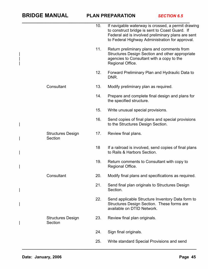
10. If navigable waterway is crossed, a permit drawing to construct bridge is sent to Coast Guard. If Federal aid is involved preliminary plans are sent to Federal Highway Administration for approval.
11. Return preliminary plans and comments from
| Structures Design Section and other appropriate | agencies to Consultant with a copy to the | Regional Office.
12. Forward Preliminary Plan and Hydraulic Data to DNR.
Consultant 13. Modify preliminary plan as required.
14. Prepare and complete final design and plans for
the specified structure.
15. Write unusual special provisions.
16. Send copies of final plans and special provisions | to the Structures Design Section.
Structures Design 17. Review final plans.
| Section
18 If a railroad is involved, send copies of final plans | to Rails & Harbors Section.
19. Return comments to Consultant with copy to
| Regional Office.
Consultant 20. Modify final plans and specifications as required.
21. Send final plan originals to Structures Design | Section.
22. Send applicable Structure Inventory Data form to | Structures Design Section. These forms are
available on DTID Network. Structures Design 23. Review final plan originals.
| Section
24. Sign final originals. 25. Write standard Special Provisions and send
BRIDGE MANUAL PLAN PREPARATION __________________________________________________________________________
_____________________________________________________________________________ Date: January, 2006 Page 46
SECTION 6.5
| plan originals to Bureau of Project Development. | Bureau of Project 26. Prepare final approved bridge plans for pre- | Development contract administration.
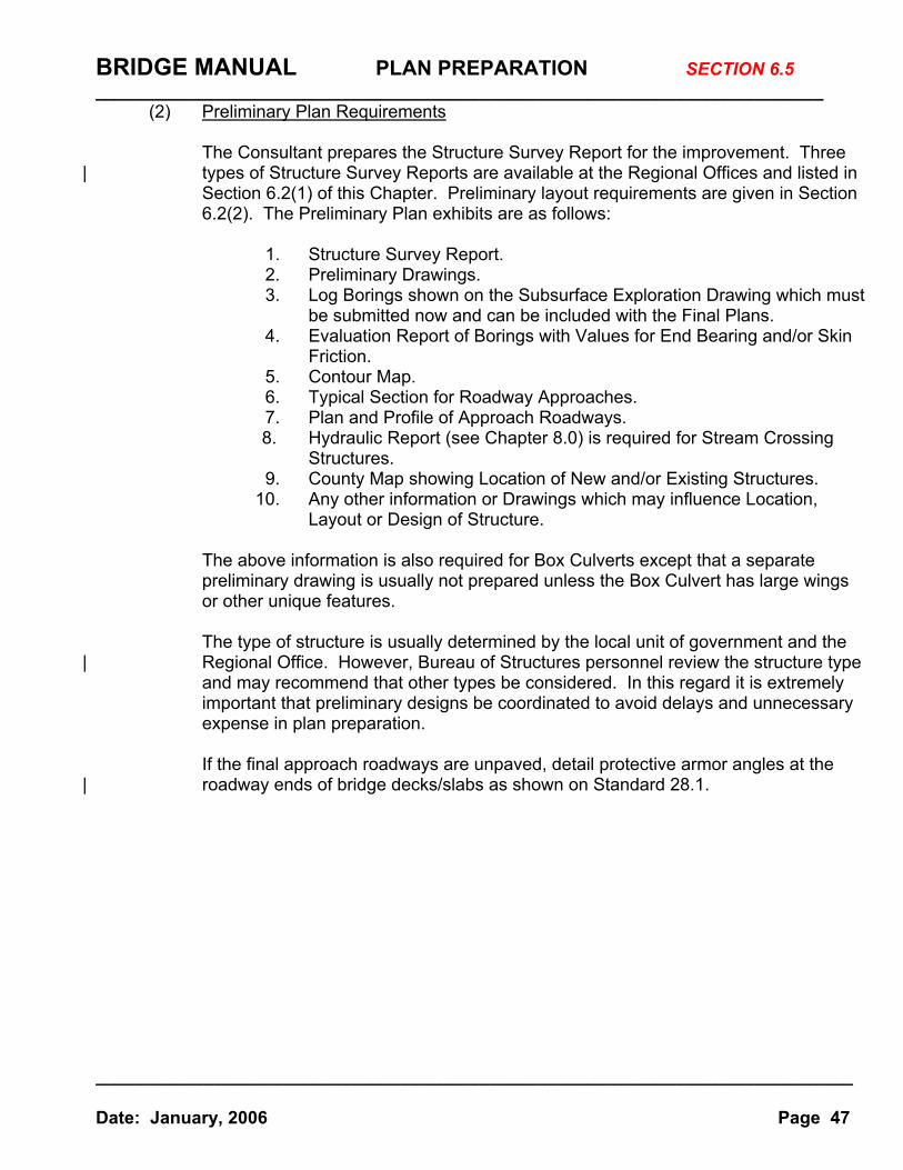
BRIDGE MANUAL PLAN PREPARATION __________________________________________________________________________
_____________________________________________________________________________ Date: January, 2006 Page 47
SECTION 6.5
(2) Preliminary Plan Requirements
The Consultant prepares the Structure Survey Report for the improvement. Three | types of Structure Survey Reports are available at the Regional Offices and listed in
Section 6.2(1) of this Chapter. Preliminary layout requirements are given in Section 6.2(2). The Preliminary Plan exhibits are as follows:
1. Structure Survey Report.
2. Preliminary Drawings. 3. Log Borings shown on the Subsurface Exploration Drawing which must
be submitted now and can be included with the Final Plans. 4. Evaluation Report of Borings with Values for End Bearing and/or Skin
Friction. 5. Contour Map. 6. Typical Section for Roadway Approaches. 7. Plan and Profile of Approach Roadways.
8. Hydraulic Report (see Chapter 8.0) is required for Stream Crossing Structures.
9. County Map showing Location of New and/or Existing Structures. 10. Any other information or Drawings which may influence Location,
Layout or Design of Structure.
The above information is also required for Box Culverts except that a separate preliminary drawing is usually not prepared unless the Box Culvert has large wings or other unique features.
The type of structure is usually determined by the local unit of government and the
| Regional Office. However, Bureau of Structures personnel review the structure type and may recommend that other types be considered. In this regard it is extremely important that preliminary designs be coordinated to avoid delays and unnecessary expense in plan preparation.
If the final approach roadways are unpaved, detail protective armor angles at the
| roadway ends of bridge decks/slabs as shown on Standard 28.1.
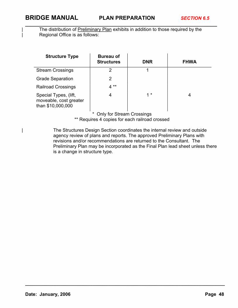
BRIDGE MANUAL PLAN PREPARATION __________________________________________________________________________
_____________________________________________________________________________ Date: January, 2006 Page 48
SECTION 6.5
| The distribution of Preliminary Plan exhibits in addition to those required by the | Regional Office is as follows:
Structure Type Bureau of Structures
DNR
FHWA
Stream Crossings 2 1
Grade Separation 2
Railroad Crossings 4 **
Special Types, (lift, moveable, cost greater than $10,000,000
4 1 * 4
* Only for Stream Crossings ** Requires 4 copies for each railroad crossed
| The Structures Design Section coordinates the internal review and outside
agency review of plans and reports. The approved Preliminary Plans with revisions and/or recommendations are returned to the Consultant. The Preliminary Plan may be incorporated as the Final Plan lead sheet unless there is a change in structure type.
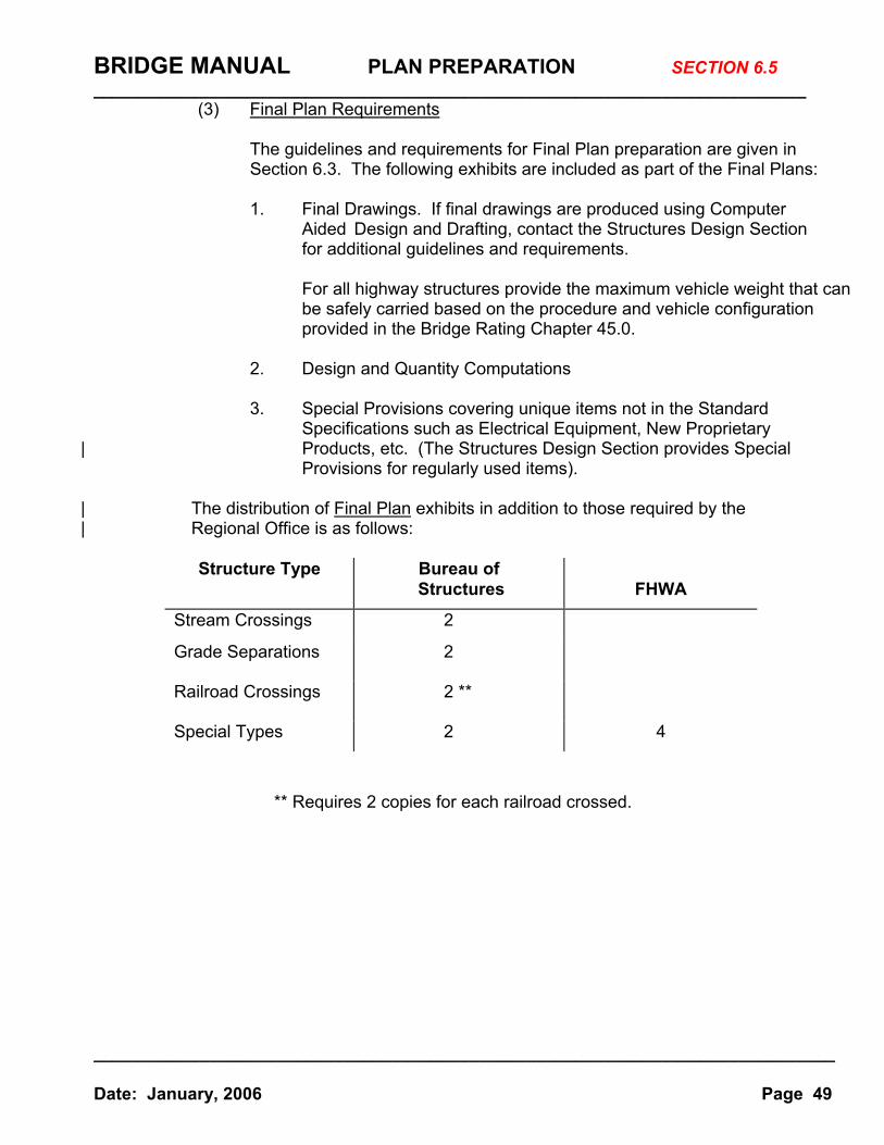
BRIDGE MANUAL PLAN PREPARATION __________________________________________________________________________
_____________________________________________________________________________ Date: January, 2006 Page 49
SECTION 6.5
(3) Final Plan Requirements
The guidelines and requirements for Final Plan preparation are given in Section 6.3. The following exhibits are included as part of the Final Plans:
1. Final Drawings. If final drawings are produced using Computer
Aided Design and Drafting, contact the Structures Design Section for additional guidelines and requirements.
For all highway structures provide the maximum vehicle weight that can be safely carried based on the procedure and vehicle configuration provided in the Bridge Rating Chapter 45.0.
2. Design and Quantity Computations
3. Special Provisions covering unique items not in the Standard
Specifications such as Electrical Equipment, New Proprietary | Products, etc. (The Structures Design Section provides Special
Provisions for regularly used items).
| The distribution of Final Plan exhibits in addition to those required by the | Regional Office is as follows:
Structure Type Bureau of
Structures
FHWA
Stream Crossings 2
Grade Separations 2
Railroad Crossings 2 **
Special Types 2 4
** Requires 2 copies for each railroad crossed.

BRIDGE MANUAL PLAN PREPARATION __________________________________________________________________________
_____________________________________________________________________________ Date: January, 2006 Page 50
SECTION 6.5
On Federal or State Aid projects the contracts are let and awarded by the Wisconsin Department of Transportation. Shop drawing review and fabrication inspection are generally done by the Metals Fabrication and Inspection Unit. However, in some cases the consultant may check the shop drawings and an outside agency may inspect the fabrication. The Consultant contract specifies the scope of the work to be performed by the Consultant. Construction supervision and final acceptance of the project are provided by the State.
(4) Design Aids & Specifications
The following items are available for assistance in the preparation of structure plans on the department extranet sites:
Bridge Manual Highway Structures Information System (HSI) English insert sheets English standard details English sign bridges Posted bridge map Standard bridge CADD files Structure survey reports and check lists Structure costs Special Provisions https://trust.dot.state.wi.us/extntgtwy/dtid_bos/extranet/structures/index.htm Contact: [email protected], 608-266-5088 [email protected], 608-266-5161 Paper Copies Price* Source
Bridge Manual Text $100 Structures Dev.-Room 601, 608-267-3577 Bridge Manual Update Service $70 Structures Dev.-Room 601, 608-267-3577
Facilities Development Manual
https://trust.dot.state.wi.us/extntgtwy/fdm/ Contact: [email protected], 608-266-9349
Wisconsin Standard Specifications
Construction and Materials Manual https://trust.dot.state.wi.us/extntgtwy/dtidcons/constnds/ Contact: [email protected], 608-266-8461
Other web sites:
AASHTO Specifications https://bookstore.transportation.org AREMA Specification http://www.arema.org
* Prices listed do not include Wisconsin Sales Tax (5%) and Dane County
Sales Tax (1/2%) which must be added to in-state orders.
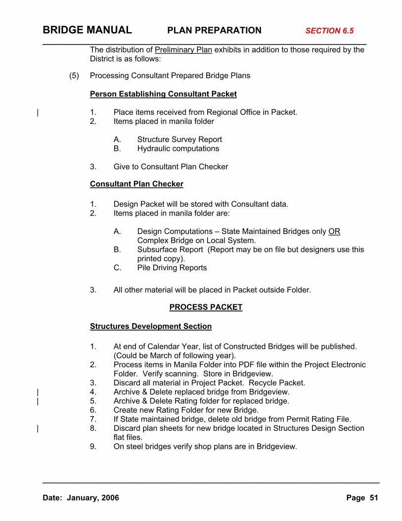
BRIDGE MANUAL PLAN PREPARATION __________________________________________________________________________
_____________________________________________________________________________ Date: January, 2006 Page 51
SECTION 6.5
The distribution of Preliminary Plan exhibits in addition to those required by the District is as follows:
(5) Processing Consultant Prepared Bridge Plans
Person Establishing Consultant Packet
| 1. Place items received from Regional Office in Packet. 2. Items placed in manila folder A. Structure Survey Report
B. Hydraulic computations
3. Give to Consultant Plan Checker
Consultant Plan Checker
1. Design Packet will be stored with Consultant data. 2. Items placed in manila folder are:
A. Design Computations – State Maintained Bridges only OR
Complex Bridge on Local System. B. Subsurface Report (Report may be on file but designers use this
printed copy). C. Pile Driving Reports
3. All other material will be placed in Packet outside Folder.
PROCESS PACKET
Structures Development Section
1. At end of Calendar Year, list of Constructed Bridges will be published. (Could be March of following year).
2. Process items in Manila Folder into PDF file within the Project Electronic Folder. Verify scanning. Store in Bridgeview.
3. Discard all material in Project Packet. Recycle Packet. | 4. Archive & Delete replaced bridge from Bridgeview. | 5. Archive & Delete Rating folder for replaced bridge.
6. Create new Rating Folder for new Bridge. 7. If State maintained bridge, delete old bridge from Permit Rating File.
| 8. Discard plan sheets for new bridge located in Structures Design Section flat files.
9. On steel bridges verify shop plans are in Bridgeview.
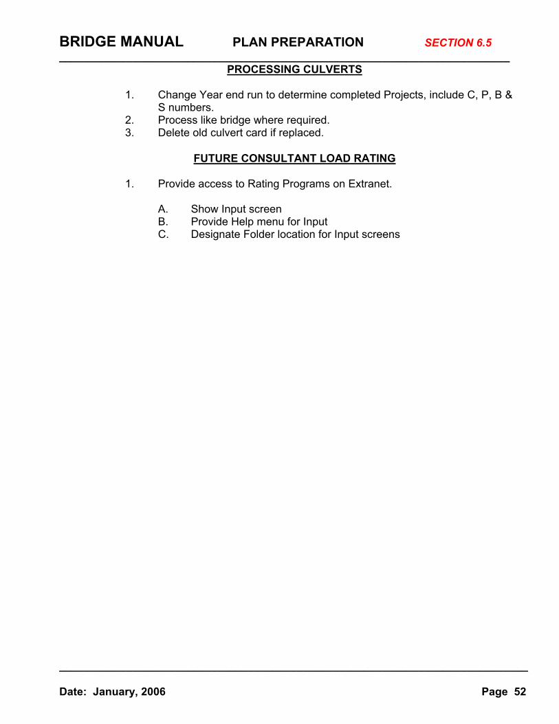
BRIDGE MANUAL PLAN PREPARATION __________________________________________________________________________
_____________________________________________________________________________ Date: January, 2006 Page 52
SECTION 6.5
PROCESSING CULVERTS
1. Change Year end run to determine completed Projects, include C, P, B & S numbers.
2. Process like bridge where required. 3. Delete old culvert card if replaced.
FUTURE CONSULTANT LOAD RATING
1. Provide access to Rating Programs on Extranet. A. Show Input screen
B. Provide Help menu for Input C. Designate Folder location for Input screens